cisco telepresence system quick set c20 …...• full hd video. • high resolution data sharing....
TRANSCRIPT
1
Cisco TelePresence System Quick Set C20 / C20 Plus and Profiles using C20 Administrator guide
D14637.05 Profile C20 and Quick Set C20 Administrator Guide TC4.1, February 2011. Copyright © 2010-2011 Cisco Systems, Inc. All rights reserved. www.cisco.com
Administrator guideFor Cisco TelePresence System Quick Set C20 / C20 Plus and Profile 42” using C20
Software version TC4.1 FEBRUARY 2011
2
Cisco TelePresence System Quick Set C20 / C20 Plus and Profiles using C20 Administrator guide
D14637.05 Profile C20 and Quick Set C20 Administrator Guide TC4.1, February 2011. Copyright © 2010-2011 Cisco Systems, Inc. All rights reserved. www.cisco.com
TA - ToC - Hidden text anchor
Thank you for choosing Cisco!
Your Cisco product has been designed to give you many years of safe, reliable operation.
This part of the product documentation is aimed at administrators working with the setup of the Quick Set C20 / C20 Plus and Profiles using Codec C20.
Our main objective with this Administrator guide is to address your goals and needs. Please let us know how well we succeeded!
May we recommend that you visit the Cisco web site regularly for updated versions of this guide.
The user documentation can be found on http://www.cisco.com/go/telepresence/docs.
How to use this guideThe top menu bar and the entries in the Table of Contents are all hyperlinks. Just click on them to go to the topic.
Table of ContentsIntroduction
Introduction ......................................................................... 5User documentation ........................................................ 5
What’s new in this version .................................................. 6Software release notes ................................................... 6Software download ......................................................... 6User documentation ........................................................ 6New features and improvements .................................... 6
Cisco TelePresence Touch for C Series ...................... 6The Advanced configuration menu ................................. 7
New settings ................................................................ 7Settings that have changed ......................................... 7Settings that have been removed................................ 7
System overview ................................................................. 8Profile 42” using Codec C20 ........................................... 8Quick Set C20 / C20 Plus ................................................. 9
Quick Set C20.............................................................. 9Quick Set C20 Plus ...................................................... 9
Web interface
The web interface ..............................................................11Connect to the codec.....................................................11Password protection of the web interface .....................11
Menu options......................................................................12
System information ............................................................13
Making calls from the web interface ..................................14
Making a snapshot ............................................................ 15
User management ............................................................. 16User roles ...................................................................... 16The default user account ............................................... 16Security mode ............................................................... 16About password and PIN-code ......................................17
Changing your password .................................................. 18
Custom wallpaper ............................................................. 19File format and picture size ........................................... 19Upload and activate the wallpaper ................................ 19
Adding a logon banner ...................................................... 20
Uploading certificates ....................................................... 21Uploading the SSL certificate ....................................... 21Uploading the Trusted CA certificates list ..................... 21
Certificates for secure logging .......................................... 22About audit logging ....................................................... 22Upload the Audit certificate list ..................................... 22Enable secure audit logging .......................................... 22
Support log files ................................................................ 23Historical log files .......................................................... 23Current log files ............................................................. 23
Viewing XML files .............................................................. 24
Software upgrade ............................................................. 25
Advanced configuration .................................................... 26
Restarting the system ....................................................... 27
Advanced configuration settings
Advanced configuration overview ..................................... 29The Audio settings ......................................................... 33The Cameras settings ................................................... 33The Conference settings ............................................... 35The H323 settings ......................................................... 37The Network settings .................................................... 39The NetworkServices settings ...................................... 43The Phonebook settings ............................................... 46The Provisioning settings .............................................. 46The Security settings .................................................... 47The SerialPort settings .................................................. 48The SIP settings ............................................................ 49The Standby settings..................................................... 50The SystemUnit settings ................................................51The Time settings .......................................................... 52The Video settings......................................................... 53The Experimental settings ............................................. 59
3
Cisco TelePresence System Quick Set C20 / C20 Plus and Profiles using C20 Administrator guide
D14637.05 Profile C20 and Quick Set C20 Administrator Guide TC4.1, February 2011. Copyright © 2010-2011 Cisco Systems, Inc. All rights reserved. www.cisco.com
Password protection
Password protection ......................................................... 62Set the Administrator settings menu password ............ 62Change your codec password ...................................... 62Change the user passwords ......................................... 63Set a root password ...................................................... 63
Appendices
Connecting the Cisco TelePresence Touch controller to Codec C20 ........................................................................ 65
About monitors when you have a Codec C20 .................. 66Connecting the monitor ................................................. 66
Connecting to HDMI 1 ............................................... 66Connecting to HDMI 2 ............................................... 66Moving the OSD using the remote control ................ 66Moving the OSD using the web interface .................. 66
Dual monitors ................................................................ 66Dual monitor configuration ......................................... 66
Optimal definition profiles ................................................. 67
ClearPath — Packet loss resilience .................................... 68
Requirement for speaker systems connected to a Cisco TelePresence C Series codec .......................................... 69
Codec C20 — The physical interface ................................ 70The front panel LEDs ..................................................... 70The rear panel ............................................................... 71Pin-out schemes ........................................................... 72
Quick Set C20 — Cable configuration ............................... 73
Quick Set C20 Plus — Cable configuration .........................74
DNAM for Profile 42” ......................................................... 75The DNAM Loudspeaker ............................................... 75The DNAM Amplifier ...................................................... 75
Technical specifications .................................................... 76Quick Set C20/C20 Plus ................................................ 76Profile 42” using C20 .................................................... 78
4
Cisco TelePresence System Quick Set C20 / C20 Plus and Profiles using C20 Administrator guide
D14637.05 Profile C20 and Quick Set C20 Administrator Guide TC4.1, February 2011. Copyright © 2010-2011 Cisco Systems, Inc. All rights reserved. www.cisco.com
Chapter 1
Introduction
5
Cisco TelePresence System Quick Set C20 / C20 Plus and Profiles using C20 Administrator guide
D14637.05 Profile C20 and Quick Set C20 Administrator Guide TC4.1, February 2011. Copyright © 2010-2011 Cisco Systems, Inc. All rights reserved. www.cisco.com
IntroductionThis document provides you with the information required to administrate your product at an advanced level.
Products covered in this guide:
• Profile 42” using C20• Quick Set C20 / C20 Plus
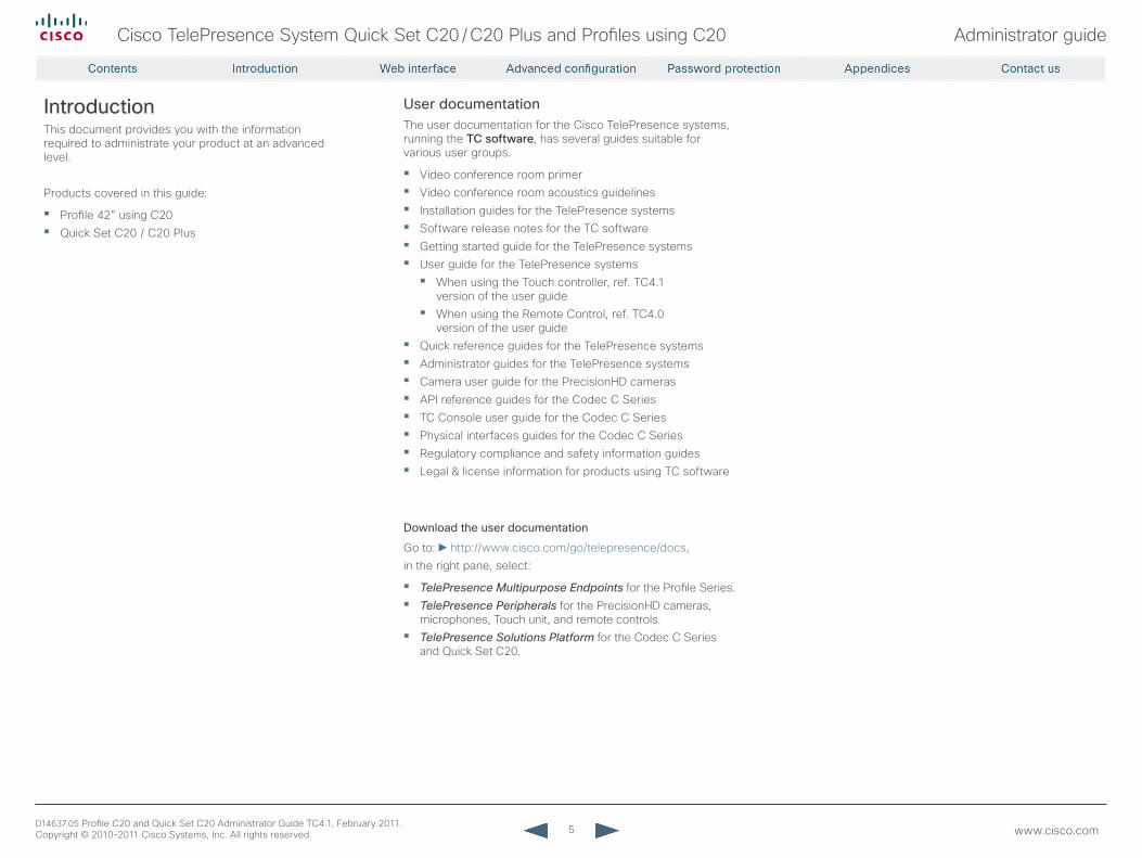
User documentationThe user documentation for the Cisco TelePresence systems, running the TC software, has several guides suitable for various user groups.
• Video conference room primer• Video conference room acoustics guidelines• Installation guides for the TelePresence systems• Software release notes for the TC software• Getting started guide for the TelePresence systems• User guide for the TelePresence systems• When using the Touch controller, ref. TC4.1
version of the user guide• When using the Remote Control, ref. TC4.0
version of the user guide• Quick reference guides for the TelePresence systems• Administrator guides for the TelePresence systems• Camera user guide for the PrecisionHD cameras• API reference guides for the Codec C Series• TC Console user guide for the Codec C Series• Physical interfaces guides for the Codec C Series• Regulatory compliance and safety information guides• Legal & license information for products using TC software
Download the user documentation
Go to: http://www.cisco.com/go/telepresence/docs,in the right pane, select:
• TelePresence Multipurpose Endpoints for the Profile Series.• TelePresence Peripherals for the PrecisionHD cameras,
microphones, Touch unit, and remote controls.• TelePresence Solutions Platform for the Codec C Series
and Quick Set C20.
6
Cisco TelePresence System Quick Set C20 / C20 Plus and Profiles using C20 Administrator guide
D14637.05 Profile C20 and Quick Set C20 Administrator Guide TC4.1, February 2011. Copyright © 2010-2011 Cisco Systems, Inc. All rights reserved. www.cisco.com
What’s new in this versionThis section provides an overview of the new and changed API commands and new features in the TC4.1.0 software version.
Software release notesFor a complete overview of the news and changes, we recommend reading the Software Release Notes (TC4).Go to: http://www.cisco.com/en/US/products/ps11422/tsd_products_support_series_home.html
Software downloadFor software download go to: http://www.cisco.com/cisco/software/navigator.html?a=a&i=rpm
User documentationGo to: http://www.cisco.com/go/telepresence/docs,in the right pane, select:
• TelePresence Multipurpose Endpoints for the Profile Series.• TelePresence Peripherals for the PrecisionHD cameras,
microphones, Touch unit, and remote controls.• TelePresence Solutions Platform for the Codec C Series
and Quick Set C20.
New features and improvements
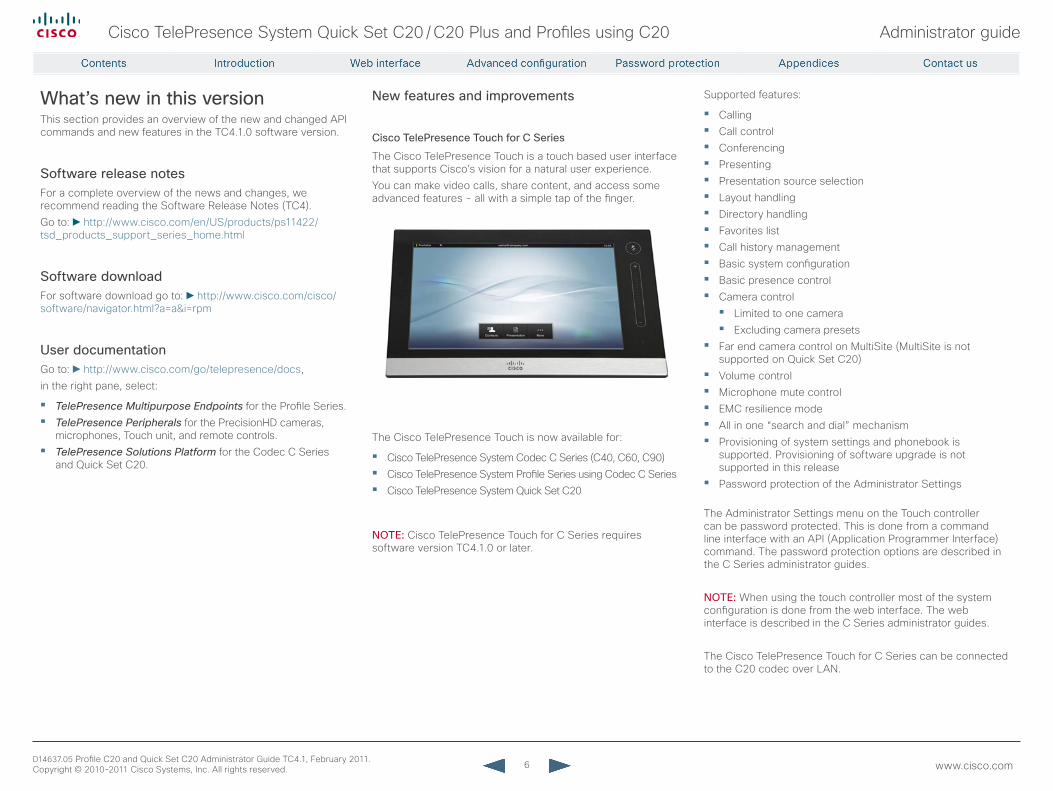
Cisco TelePresence Touch for C Series
The Cisco TelePresence Touch is a touch based user interface that supports Cisco’s vision for a natural user experience.You can make video calls, share content, and access some advanced features - all with a simple tap of the finger.
The Cisco TelePresence Touch is now available for:
• Cisco TelePresence System Codec C Series (C40, C60, C90)• Cisco TelePresence System Profile Series using Codec C Series• Cisco TelePresence System Quick Set C20
NOTE: Cisco TelePresence Touch for C Series requires software version TC4.1.0 or later.
Supported features:
• Calling• Call control• Conferencing• Presenting• Presentation source selection• Layout handling• Directory handling• Favorites list• Call history management• Basic system configuration• Basic presence control• Camera control • Limited to one camera• Excluding camera presets
• Far end camera control on MultiSite (MultiSite is not supported on Quick Set C20)
• Volume control• Microphone mute control• EMC resilience mode• All in one “search and dial” mechanism• Provisioning of system settings and phonebook is
supported. Provisioning of software upgrade is not supported in this release
• Password protection of the Administrator Settings
The Administrator Settings menu on the Touch controller can be password protected. This is done from a command line interface with an API (Application Programmer Interface) command. The password protection options are described in the C Series administrator guides.
NOTE: When using the touch controller most of the system configuration is done from the web interface. The web interface is described in the C Series administrator guides.
The Cisco TelePresence Touch for C Series can be connected to the C20 codec over LAN.
7
Cisco TelePresence System Quick Set C20 / C20 Plus and Profiles using C20 Administrator guide
D14637.05 Profile C20 and Quick Set C20 Administrator Guide TC4.1, February 2011. Copyright © 2010-2011 Cisco Systems, Inc. All rights reserved. www.cisco.com
The Advanced configuration menu
New settings
Video Input Source [1..2] Type
Settings that have changed
Provisioning Mode• Added argument “VCS”
Video SelfviewPosition• Added argument “CenterRight”
Settings that have been removed
SystemUnit Type
Experimental settings
The Experimental settings are beta settings. These settings can be used ‘as is’, and are not fully documented. NOTE: The Experimental settings are likely to change.
New settings:Experimental NetworkServices UPnP ModeExperimental NetworkServices UPnP TimeoutExperimental SystemUnit MenuType
8
Cisco TelePresence System Quick Set C20 / C20 Plus and Profiles using C20 Administrator guide
D14637.05 Profile C20 and Quick Set C20 Administrator Guide TC4.1, February 2011. Copyright © 2010-2011 Cisco Systems, Inc. All rights reserved. www.cisco.com
Power cable
Mic cables
PC cable
Ethernet cable
Profile 42”
2 × Microphones with cables
System overview
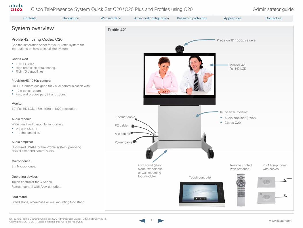
Profile 42” using Codec C20See the installation sheet for your Profile system for instructions on how to install the system.
Codec C20
• Full HD video.• High resolution data sharing.• Rich I/O capabilities.
PrecisionHD 1080p camera
Full HD Camera designed for visual communication with:• 12 × optical zoom.• Fast and precise pan, tilt and zoom.
Monitor
42” Full HD LCD, 16:9, 1080 × 1920 resolution.
Audio module
Wide band audio module supporting:• 20 kHz AAC-LD.• 1 echo canceller.
Audio amplifier
Optimized DNAM for the Profile system, providing crystal clear and natural audio.
Microphones
2 × Microphones.
Operating devices
Touch controller for C Series.Remote control with AAA batteries.
Foot stand
Stand alone, wheelbase or wall mounting foot stand.
In the base module:
• Audio amplifier (DNAM)• Codec C20
PrecisionHD 1080p camera
Monitor 42’’ Full HD LCD
Foot stand (stand alone, wheelbase or wall mounting foot module)
Remote control with batteries
Touch controller
9
Cisco TelePresence System Quick Set C20 / C20 Plus and Profiles using C20 Administrator guide
D14637.05 Profile C20 and Quick Set C20 Administrator Guide TC4.1, February 2011. Copyright © 2010-2011 Cisco Systems, Inc. All rights reserved. www.cisco.com
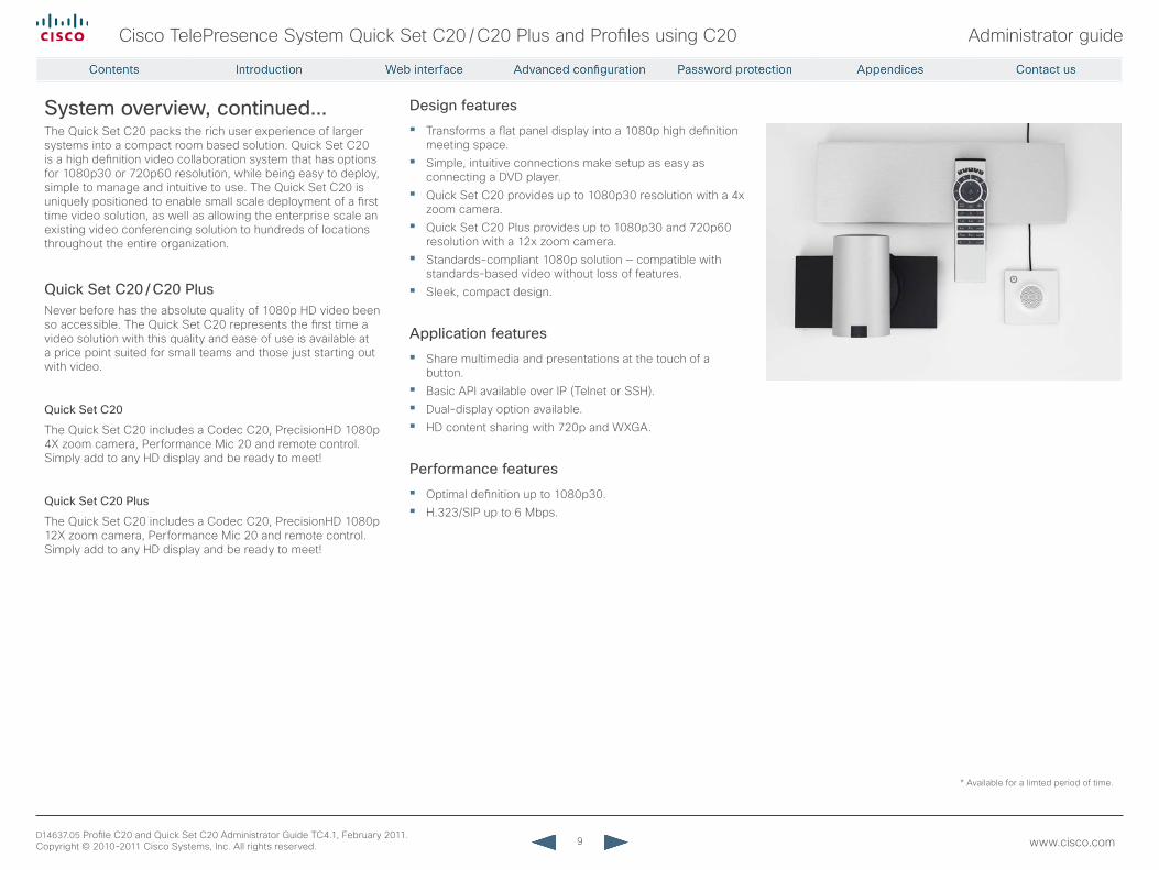
System overview, continued...The Quick Set C20 packs the rich user experience of larger systems into a compact room based solution. Quick Set C20 is a high definition video collaboration system that has options for 1080p30 or 720p60 resolution, while being easy to deploy, simple to manage and intuitive to use. The Quick Set C20 is uniquely positioned to enable small scale deployment of a first time video solution, as well as allowing the enterprise scale an existing video conferencing solution to hundreds of locations throughout the entire organization.
Quick Set C20 / C20 PlusNever before has the absolute quality of 1080p HD video been so accessible. The Quick Set C20 represents the first time a video solution with this quality and ease of use is available at a price point suited for small teams and those just starting out with video.
Quick Set C20
The Quick Set C20 includes a Codec C20, PrecisionHD 1080p 4X zoom camera, Performance Mic 20 and remote control. Simply add to any HD display and be ready to meet!
Quick Set C20 Plus
The Quick Set C20 includes a Codec C20, PrecisionHD 1080p 12X zoom camera, Performance Mic 20 and remote control. Simply add to any HD display and be ready to meet!
Design features
• Transforms a flat panel display into a 1080p high definition meeting space.
• Simple, intuitive connections make setup as easy as connecting a DVD player.
• Quick Set C20 provides up to 1080p30 resolution with a 4x zoom camera.
• Quick Set C20 Plus provides up to 1080p30 and 720p60 resolution with a 12x zoom camera.
• Standards-compliant 1080p solution — compatible with standards-based video without loss of features.
• Sleek, compact design.
Application features
• Share multimedia and presentations at the touch of a button.
• Basic API available over IP (Telnet or SSH).• Dual-display option available.• HD content sharing with 720p and WXGA.
Performance features
• Optimal definition up to 1080p30.• H.323/SIP up to 6 Mbps.
* Available for a limted period of time.

10
Cisco TelePresence System Quick Set C20 / C20 Plus and Profiles using C20 Administrator guide
D14637.05 Profile C20 and Quick Set C20 Administrator Guide TC4.1, February 2011. Copyright © 2010-2011 Cisco Systems, Inc. All rights reserved. www.cisco.com
Chapter 2
Web interface
11
Cisco TelePresence System Quick Set C20 / C20 Plus and Profiles using C20 Administrator guide
D14637.05 Profile C20 and Quick Set C20 Administrator Guide TC4.1, February 2011. Copyright © 2010-2011 Cisco Systems, Inc. All rights reserved. www.cisco.com
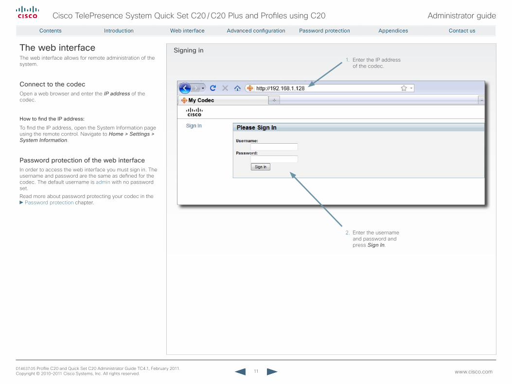
Signing inThe web interfaceThe web interface allows for remote administration of the system.
Connect to the codecOpen a web browser and enter the IP address of the codec.
How to find the IP address:
To find the IP address, open the System Information page using the remote control. Navigate to Home > Settings > System Information.
Password protection of the web interfaceIn order to access the web interface you must sign in. The username and password are the same as defined for the codec. The default username is admin with no password set.Read more about password protecting your codec in the
Password protection chapter.
1. Enter the IP address of the codec.
2. Enter the username and password and press Sign In.
12
Cisco TelePresence System Quick Set C20 / C20 Plus and Profiles using C20 Administrator guide
D14637.05 Profile C20 and Quick Set C20 Administrator Guide TC4.1, February 2011. Copyright © 2010-2011 Cisco Systems, Inc. All rights reserved. www.cisco.com
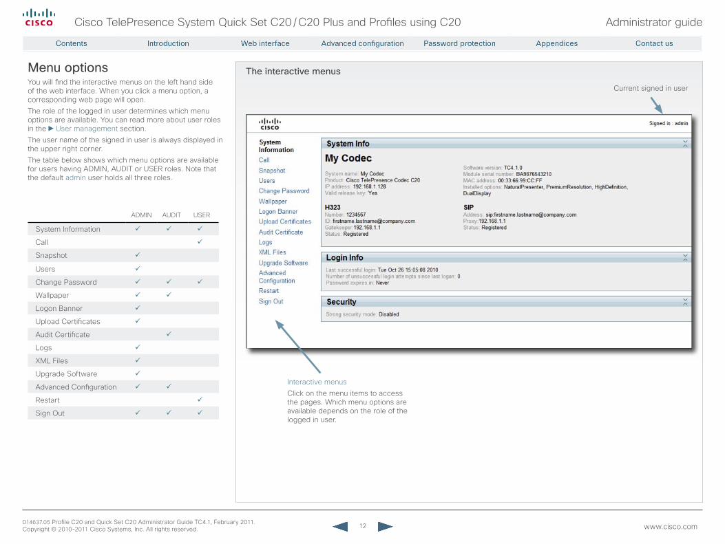
The interactive menus
Interactive menusClick on the menu items to access the pages. Which menu options are available depends on the role of the logged in user.
Current signed in user
Menu optionsYou will find the interactive menus on the left hand side of the web interface. When you click a menu option, a corresponding web page will open.The role of the logged in user determines which menu options are available. You can read more about user roles in the User management section.The user name of the signed in user is always displayed in the upper right corner.The table below shows which menu options are available for users having ADMIN, AUDIT or USER roles. Note that the default admin user holds all three roles.
ADMIN AUDIT USER
System Information
Call
Snapshot
Users
Change Password
Wallpaper
Logon Banner
Upload Certificates
Audit Certificate
Logs
XML Files
Upgrade Software
Advanced Configuration
Restart
Sign Out
13
Cisco TelePresence System Quick Set C20 / C20 Plus and Profiles using C20 Administrator guide
D14637.05 Profile C20 and Quick Set C20 Administrator Guide TC4.1, February 2011. Copyright © 2010-2011 Cisco Systems, Inc. All rights reserved. www.cisco.com
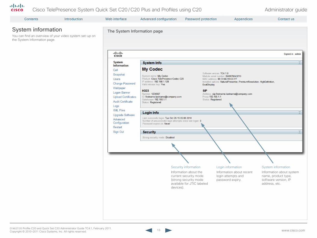
The System Information pageSystem informationYou can find an overview of your video system set-up on the System Information page.
Security information Information about the current security mode (strong security mode available for JTIC labeled devices).
Login information Information about recent login attempts and password expiry.
System information Information about system name, product type, software version, IP address, etc.
14
Cisco TelePresence System Quick Set C20 / C20 Plus and Profiles using C20 Administrator guide
D14637.05 Profile C20 and Quick Set C20 Administrator Guide TC4.1, February 2011. Copyright © 2010-2011 Cisco Systems, Inc. All rights reserved. www.cisco.com
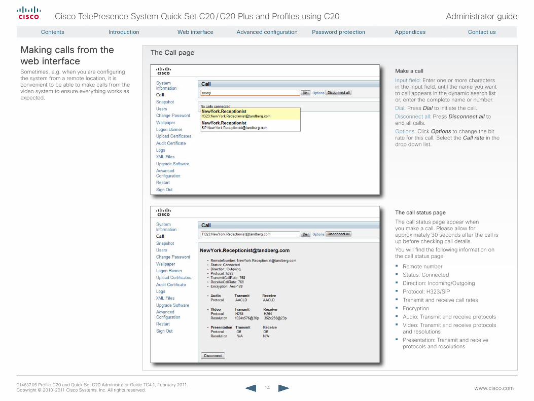
The Call pageMaking calls from the web interfaceSometimes, e.g. when you are configuring the system from a remote location, it is convenient to be able to make calls from the video system to ensure everything works as expected.
Make a call
Input field: Enter one or more characters in the input field, until the name you want to call appears in the dynamic search list or, enter the complete name or number.Dial: Press Dial to initiate the call.Disconnect all: Press Disconnect all to end all calls.Options: Click Options to change the bit rate for this call. Select the Call rate in the drop down list.
The call status page
The call status page appear when you make a call. Please allow for approximately 30 seconds after the call is up before checking call details.You will find the following information on the call status page:
• Remote number• Status: Connected• Direction: Incoming/Outgoing• Protocol: H323/SIP• Transmit and receive call rates• Encryption• Audio: Transmit and receive protocols• Video: Transmit and receive protocols
and resolutions• Presentation: Transmit and receive
protocols and resolutions
15
Cisco TelePresence System Quick Set C20 / C20 Plus and Profiles using C20 Administrator guide
D14637.05 Profile C20 and Quick Set C20 Administrator Guide TC4.1, February 2011. Copyright © 2010-2011 Cisco Systems, Inc. All rights reserved. www.cisco.com
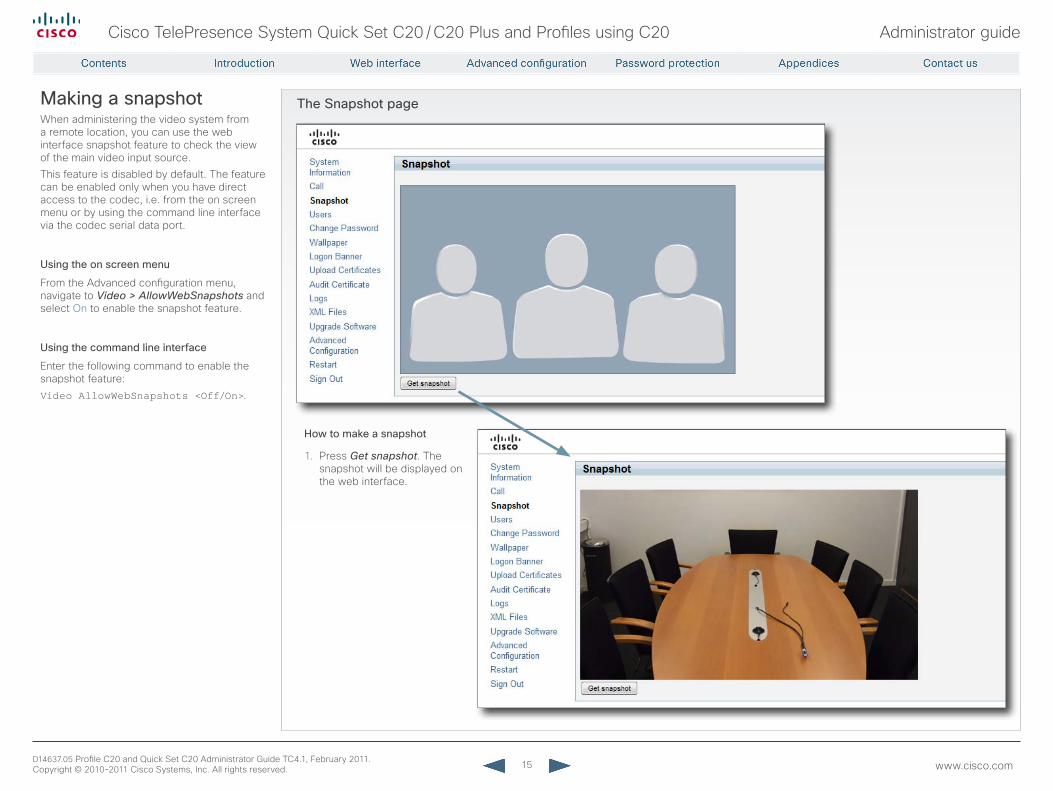
The Snapshot pageMaking a snapshotWhen administering the video system from a remote location, you can use the web interface snapshot feature to check the view of the main video input source.This feature is disabled by default. The feature can be enabled only when you have direct access to the codec, i.e. from the on screen menu or by using the command line interface via the codec serial data port.
Using the on screen menu
From the Advanced configuration menu, navigate to Video > AllowWebSnapshots and select On to enable the snapshot feature.
Using the command line interface
Enter the following command to enable the snapshot feature:Video AllowWebSnapshots <Off/On>.
How to make a snapshot
1. Press Get snapshot. The snapshot will be displayed on the web interface.
16
Cisco TelePresence System Quick Set C20 / C20 Plus and Profiles using C20 Administrator guide
D14637.05 Profile C20 and Quick Set C20 Administrator Guide TC4.1, February 2011. Copyright © 2010-2011 Cisco Systems, Inc. All rights reserved. www.cisco.com
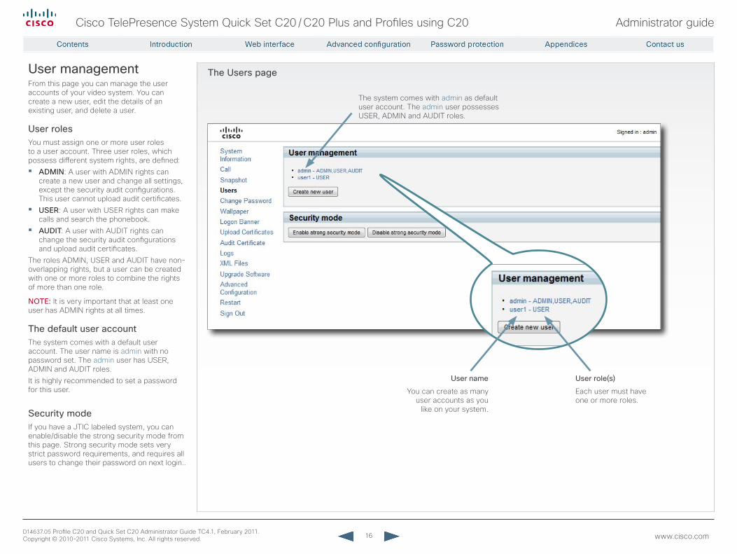
The Users pageUser managementFrom this page you can manage the user accounts of your video system. You can create a new user, edit the details of an existing user, and delete a user.
User rolesYou must assign one or more user roles to a user account. Three user roles, which possess different system rights, are defined:• ADMIN: A user with ADMIN rights can
create a new user and change all settings, except the security audit configurations. This user cannot upload audit certificates.
• USEr: A user with USER rights can make calls and search the phonebook.
• AUDIT: A user with AUDIT rights can change the security audit configurations and upload audit certificates.
The roles ADMIN, USER and AUDIT have non-overlapping rights, but a user can be created with one or more roles to combine the rights of more than one role.
NOTE: It is very important that at least one user has ADMIN rights at all times.
The default user accountThe system comes with a default user account. The user name is admin with no password set. The admin user has USER, ADMIN and AUDIT roles. It is highly recommended to set a password for this user.
Security modeIf you have a JTIC labeled system, you can enable/disable the strong security mode from this page. Strong security mode sets very strict password requirements, and requires all users to change their password on next login..
The system comes with admin as default user account. The admin user possesses USER, ADMIN and AUDIT roles.
User name
You can create as many user accounts as you
like on your system.
User role(s)
Each user must have one or more roles.
17
Cisco TelePresence System Quick Set C20 / C20 Plus and Profiles using C20 Administrator guide
D14637.05 Profile C20 and Quick Set C20 Administrator Guide TC4.1, February 2011. Copyright © 2010-2011 Cisco Systems, Inc. All rights reserved. www.cisco.com
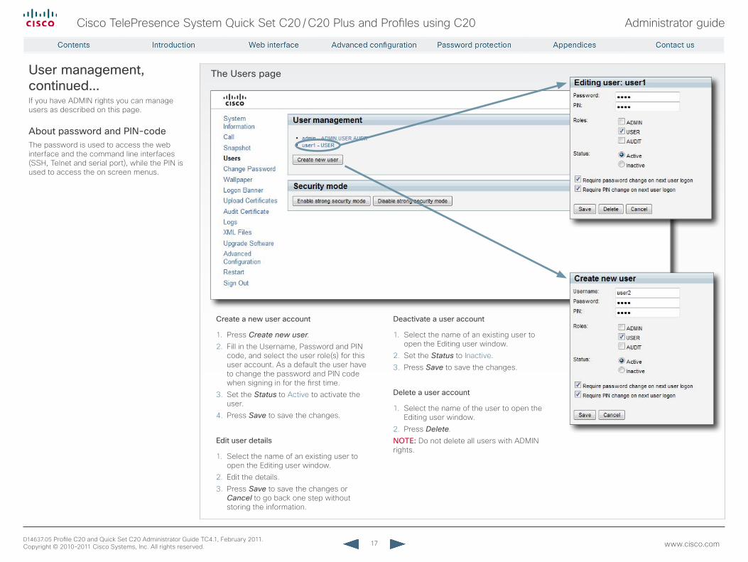
The Users pageUser management, continued...If you have ADMIN rights you can manage users as described on this page.
About password and PIN-codeThe password is used to access the web interface and the command line interfaces (SSH, Telnet and serial port), while the PIN is used to access the on screen menus.
Create a new user account
1. Press Create new user.2. Fill in the Username, Password and PIN
code, and select the user role(s) for this user account. As a default the user have to change the password and PIN code when signing in for the first time.
3. Set the Status to Active to activate the user.
4. Press Save to save the changes.
Edit user details
1. Select the name of an existing user to open the Editing user window.
2. Edit the details.3. Press Save to save the changes or
Cancel to go back one step without storing the information.
Deactivate a user account
1. Select the name of an existing user to open the Editing user window.
2. Set the Status to Inactive.3. Press Save to save the changes.
Delete a user account
1. Select the name of the user to open the Editing user window.
2. Press Delete.NOTE: Do not delete all users with ADMIN rights.
18
Cisco TelePresence System Quick Set C20 / C20 Plus and Profiles using C20 Administrator guide
D14637.05 Profile C20 and Quick Set C20 Administrator Guide TC4.1, February 2011. Copyright © 2010-2011 Cisco Systems, Inc. All rights reserved. www.cisco.com
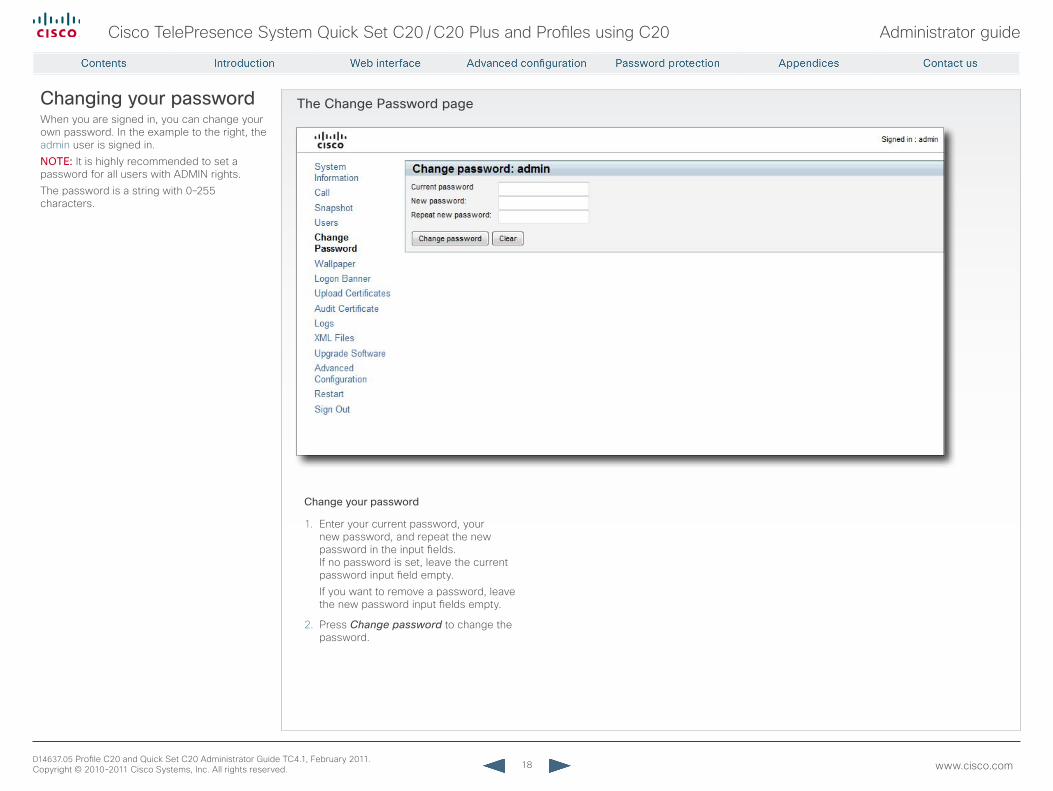
The Change Password pageChanging your passwordWhen you are signed in, you can change your own password. In the example to the right, the admin user is signed in.NOTE: It is highly recommended to set a password for all users with ADMIN rights.The password is a string with 0–255 characters.
Change your password
1. Enter your current password, your new password, and repeat the new password in the input fields.If no password is set, leave the current password input field empty.If you want to remove a password, leave the new password input fields empty.
2. Press Change password to change the password.
19
Cisco TelePresence System Quick Set C20 / C20 Plus and Profiles using C20 Administrator guide
D14637.05 Profile C20 and Quick Set C20 Administrator Guide TC4.1, February 2011. Copyright © 2010-2011 Cisco Systems, Inc. All rights reserved. www.cisco.com
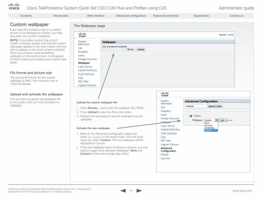
The Wallpaper pageCustom wallpaperIf you want the company logo or a custom picture to be displayed on screen, you may very well use a custom wallpaper.NOTE: If your video system has a touch screen controller, please note that the custom wall paper applies to the main screen only and will not appear on the touch screen controller. When you choose a new predefined wallpaper on the touch screen, it will appear on both screens and replace your custom wall paper.
File format and picture sizeThe picture file format for the custom wallpaper is PNG. The maximum size is 1920x1200pixels.
Upload and activate the wallpaperFirst you have to upload the wallpaper file to the codec, then you must activate the wallpaper.
Upload the custom wallpaper file
1. Press Browse... and locate the wallpaper file (.PNG).2. Press Upload to save the file to the codec.3. Refresh the web page to see the wallpaper you just
uploaded.
Activate the new wallpaper
1. Move to the Advanced configuration page and enter wallpaper in the search field. From the drop down list, select Custom. The new wallpaper will be displayed on screen.
2. If the new wallpaper does not show on screen, you may have to toggle once between Wallpaper: None and Custom to make the change take effect.
20
Cisco TelePresence System Quick Set C20 / C20 Plus and Profiles using C20 Administrator guide
D14637.05 Profile C20 and Quick Set C20 Administrator Guide TC4.1, February 2011. Copyright © 2010-2011 Cisco Systems, Inc. All rights reserved. www.cisco.com
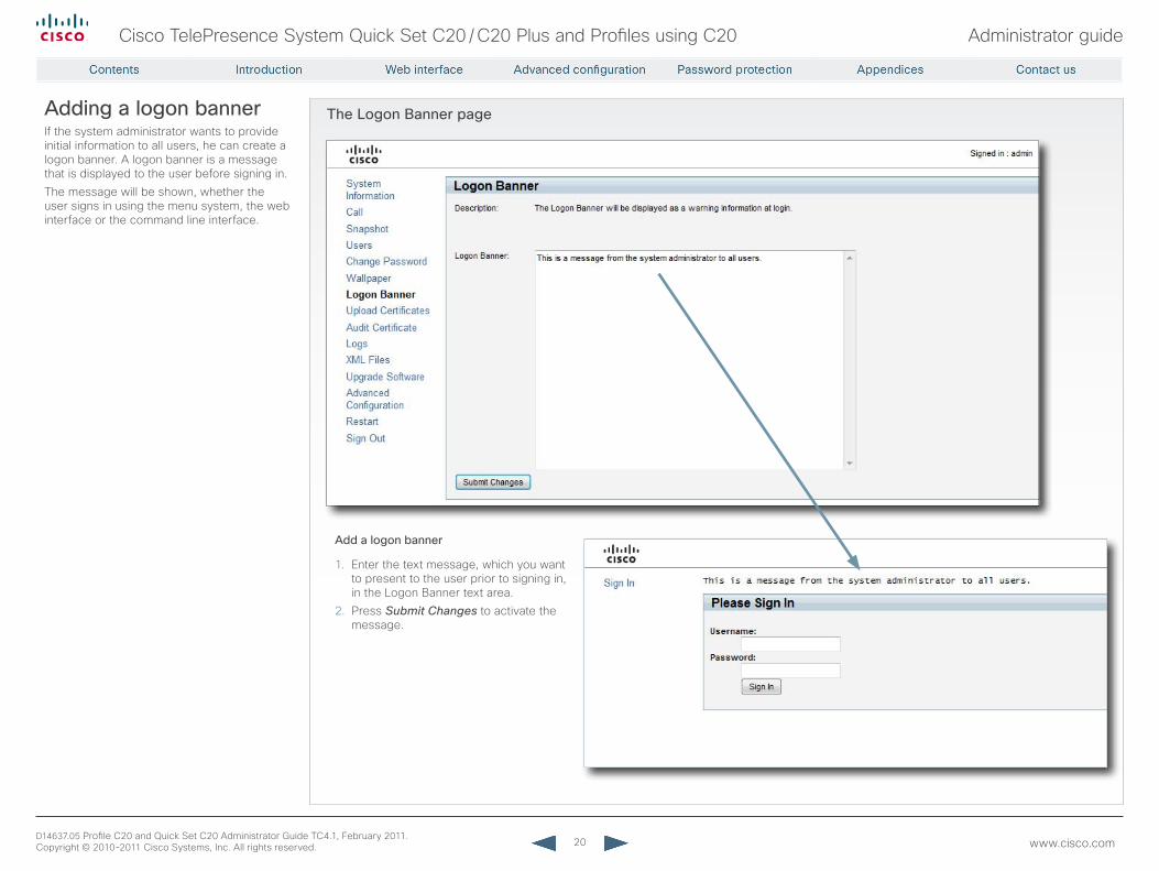
The Logon Banner pageAdding a logon bannerIf the system administrator wants to provide initial information to all users, he can create a logon banner. A logon banner is a message that is displayed to the user before signing in.The message will be shown, whether the user signs in using the menu system, the web interface or the command line interface.
Add a logon banner
1. Enter the text message, which you want to present to the user prior to signing in, in the Logon Banner text area.
2. Press Submit Changes to activate the message.
21
Cisco TelePresence System Quick Set C20 / C20 Plus and Profiles using C20 Administrator guide
D14637.05 Profile C20 and Quick Set C20 Administrator Guide TC4.1, February 2011. Copyright © 2010-2011 Cisco Systems, Inc. All rights reserved. www.cisco.com
The Upload Certificates page
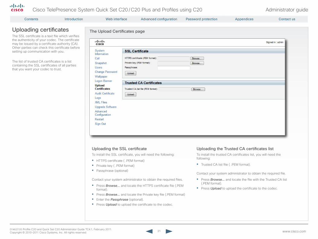
Uploading the SSL certificateTo install the SSL certificate, you will need the following:
• HTTPS certificate ( .PEM format)• Private key ( .PEM format)• Passphrase (optional)
Contact your system administrator to obtain the required files.
• Press Browse... and locate the HTTPS certificate file (.PEM format).
• Press Browse... and locate the Private key file (.PEM format)• Enter the Passphrase (optional).• Press Upload to upload the certificate to the codec.
Uploading certificatesThe SSL certificate is a text file which verifies the authenticity of your codec. The certificate may be issued by a certificate authority (CA). Other parties can check this certificate before setting up communication with you.
The list of trusted CA certificates is a list containing the SSL certificates of all parties that you want your codec to trust.
Uploading the Trusted CA certificates listTo install the trusted CA certificates list, you will need the following:
• Trusted CA list file ( .PEM format).
Contact your system administrator to obtain the required file.
• Press Browse... and locate the file with the Trusted CA list (.PEM format).
• Press Upload to upload the certificate to the codec.
22
Cisco TelePresence System Quick Set C20 / C20 Plus and Profiles using C20 Administrator guide
D14637.05 Profile C20 and Quick Set C20 Administrator Guide TC4.1, February 2011. Copyright © 2010-2011 Cisco Systems, Inc. All rights reserved. www.cisco.com
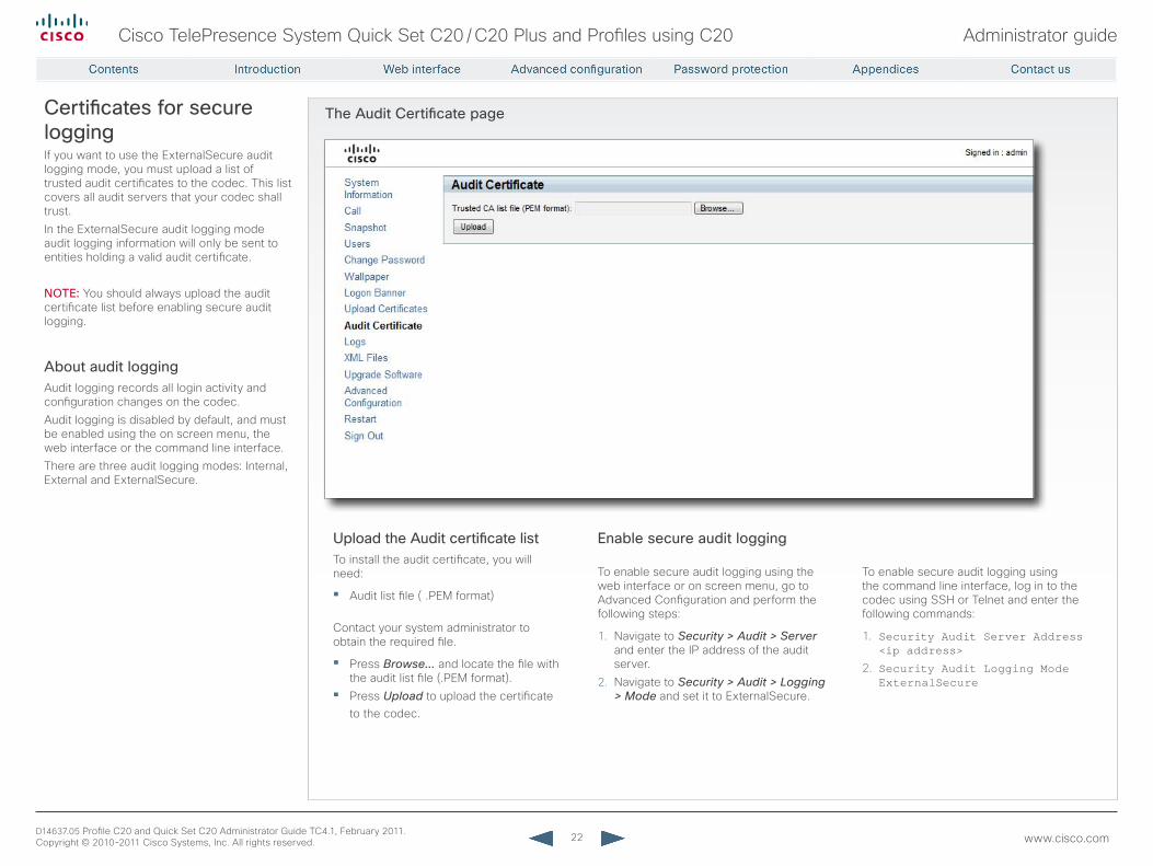
The Audit Certificate pageCertificates for secure loggingIf you want to use the ExternalSecure audit logging mode, you must upload a list of trusted audit certificates to the codec. This list covers all audit servers that your codec shall trust.In the ExternalSecure audit logging mode audit logging information will only be sent to entities holding a valid audit certificate.
NOTE: You should always upload the audit certificate list before enabling secure audit logging.
About audit loggingAudit logging records all login activity and configuration changes on the codec. Audit logging is disabled by default, and must be enabled using the on screen menu, the web interface or the command line interface.There are three audit logging modes: Internal, External and ExternalSecure.
Upload the Audit certificate listTo install the audit certificate, you will need:
• Audit list file ( .PEM format)
Contact your system administrator to obtain the required file.
• Press Browse... and locate the file with the audit list file (.PEM format).
• Press Upload to upload the certificate to the codec.
Enable secure audit logging
To enable secure audit logging using the web interface or on screen menu, go to Advanced Configuration and perform the following steps:
1. Navigate to Security > Audit > Server and enter the IP address of the audit server.
2. Navigate to Security > Audit > Logging > Mode and set it to ExternalSecure.
To enable secure audit logging using the command line interface, log in to the codec using SSH or Telnet and enter the following commands:
1. Security Audit Server Address <ip address>
2. Security Audit Logging Mode ExternalSecure
23
Cisco TelePresence System Quick Set C20 / C20 Plus and Profiles using C20 Administrator guide
D14637.05 Profile C20 and Quick Set C20 Administrator Guide TC4.1, February 2011. Copyright © 2010-2011 Cisco Systems, Inc. All rights reserved. www.cisco.com
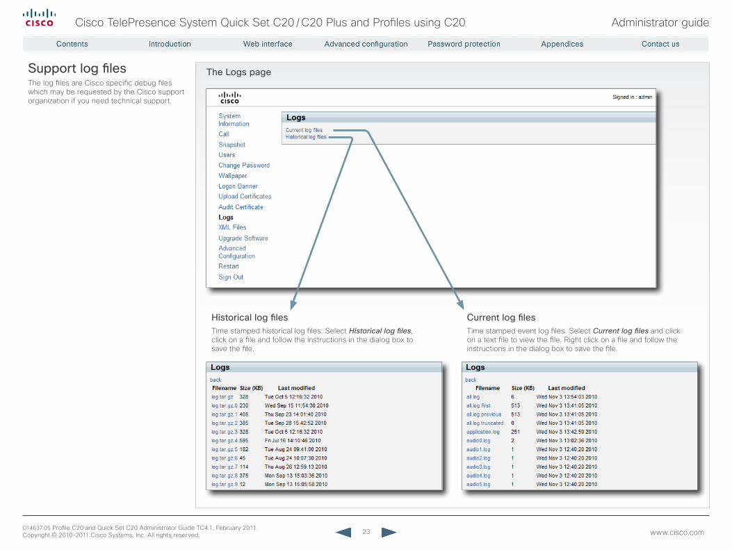
The Logs pageSupport log filesThe log files are Cisco specific debug files which may be requested by the Cisco support organization if you need technical support.
Historical log filesTime stamped historical log files. Select Historical log files, click on a file and follow the instructions in the dialog box to save the file.
Current log filesTime stamped event log files. Select Current log files and click on a text file to view the file. Right click on a file and follow the instructions in the dialog box to save the file.
24
Cisco TelePresence System Quick Set C20 / C20 Plus and Profiles using C20 Administrator guide
D14637.05 Profile C20 and Quick Set C20 Administrator Guide TC4.1, February 2011. Copyright © 2010-2011 Cisco Systems, Inc. All rights reserved. www.cisco.com
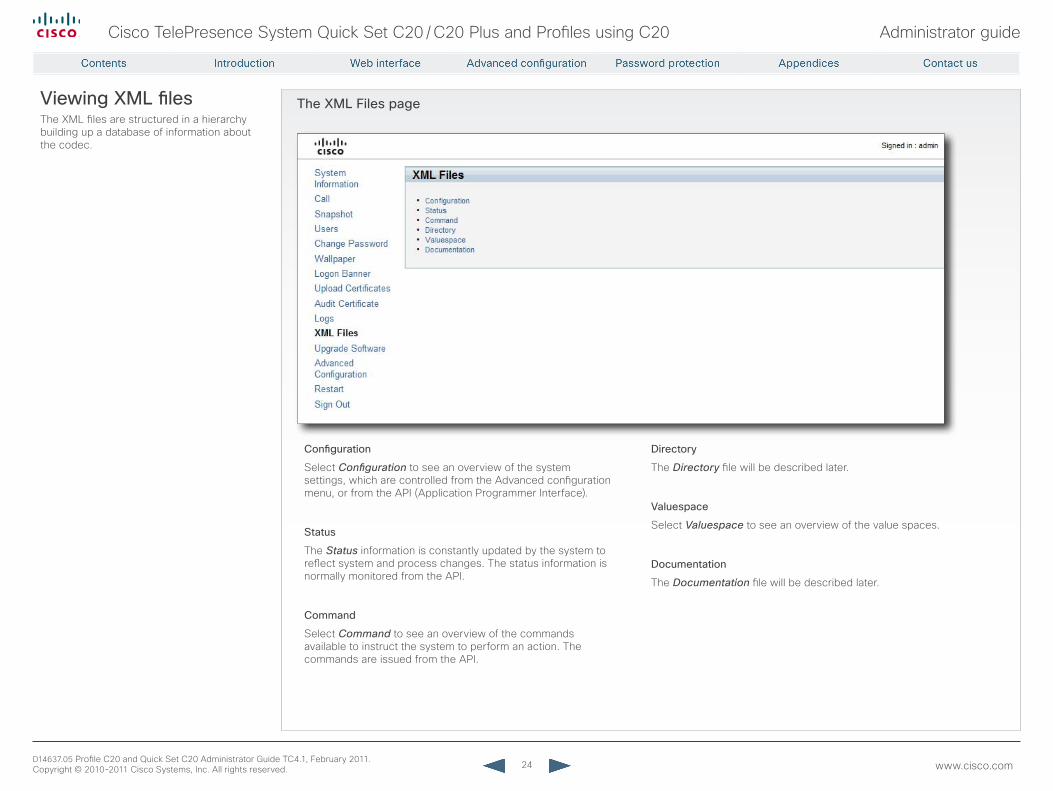
The XML Files pageViewing XML filesThe XML files are structured in a hierarchy building up a database of information about the codec.
Configuration
Select Configuration to see an overview of the system settings, which are controlled from the Advanced configuration menu, or from the API (Application Programmer Interface).
Status
The Status information is constantly updated by the system to reflect system and process changes. The status information is normally monitored from the API.
Command
Select Command to see an overview of the commands available to instruct the system to perform an action. The commands are issued from the API.
Directory
The Directory file will be described later.
Valuespace
Select Valuespace to see an overview of the value spaces.
Documentation
The Documentation file will be described later.
25
Cisco TelePresence System Quick Set C20 / C20 Plus and Profiles using C20 Administrator guide
D14637.05 Profile C20 and Quick Set C20 Administrator Guide TC4.1, February 2011. Copyright © 2010-2011 Cisco Systems, Inc. All rights reserved. www.cisco.com
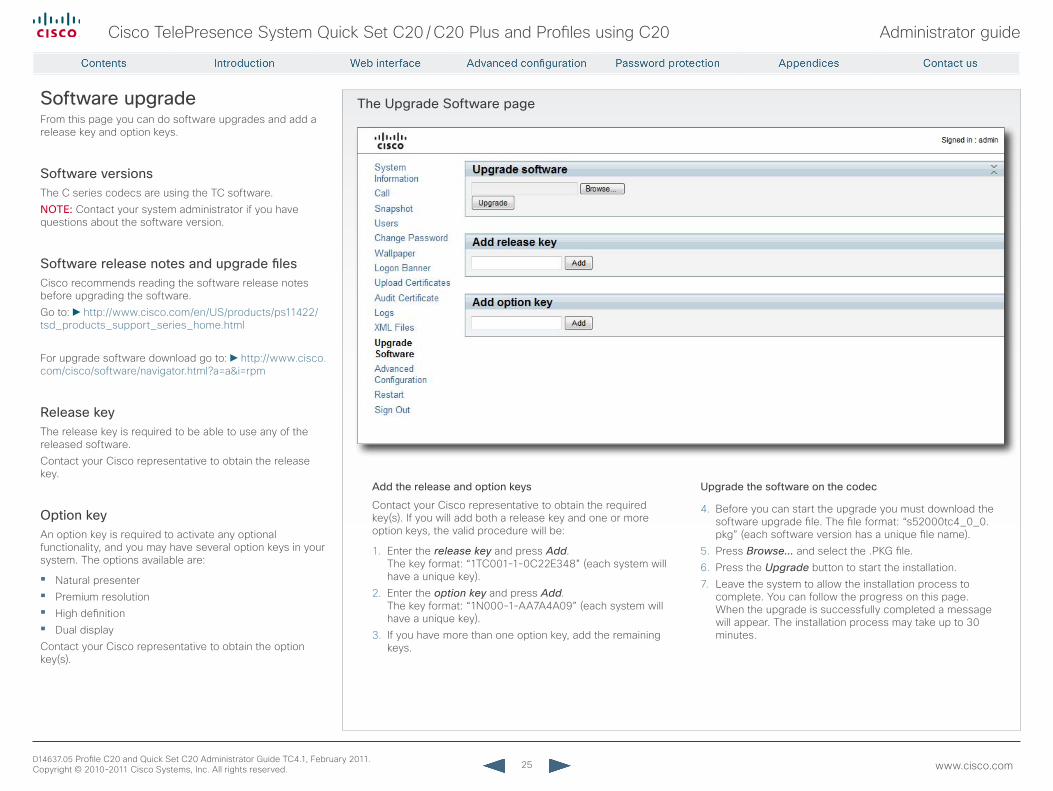
The Upgrade Software pageSoftware upgradeFrom this page you can do software upgrades and add a release key and option keys.
Software versionsThe C series codecs are using the TC software. NOTE: Contact your system administrator if you have questions about the software version.
Software release notes and upgrade filesCisco recommends reading the software release notes before upgrading the software. Go to: http://www.cisco.com/en/US/products/ps11422/tsd_products_support_series_home.html
For upgrade software download go to: http://www.cisco.com/cisco/software/navigator.html?a=a&i=rpm
release keyThe release key is required to be able to use any of the released software.Contact your Cisco representative to obtain the release key.
Option keyAn option key is required to activate any optional functionality, and you may have several option keys in your system. The options available are:
• Natural presenter• Premium resolution• High definition• Dual displayContact your Cisco representative to obtain the option key(s).
Add the release and option keys
Contact your Cisco representative to obtain the required key(s). If you will add both a release key and one or more option keys, the valid procedure will be:
1. Enter the release key and press Add. The key format: “1TC001-1-0C22E348” (each system will have a unique key).
2. Enter the option key and press Add. The key format: “1N000-1-AA7A4A09” (each system will have a unique key).
3. If you have more than one option key, add the remaining keys.
Upgrade the software on the codec
4. Before you can start the upgrade you must download the software upgrade file. The file format: “s52000tc4_0_0.pkg” (each software version has a unique file name).
5. Press Browse... and select the .PKG file.6. Press the Upgrade button to start the installation.7. Leave the system to allow the installation process to
complete. You can follow the progress on this page. When the upgrade is successfully completed a message will appear. The installation process may take up to 30 minutes.
26
Cisco TelePresence System Quick Set C20 / C20 Plus and Profiles using C20 Administrator guide
D14637.05 Profile C20 and Quick Set C20 Administrator Guide TC4.1, February 2011. Copyright © 2010-2011 Cisco Systems, Inc. All rights reserved. www.cisco.com
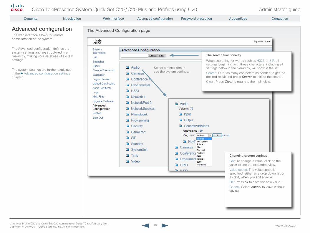
The Advanced Configuration pageAdvanced configurationThe web interface allows for remote administration of the system.
The Advanced configuration defines the system settings and are structured in a hierarchy, making up a database of system settings.
The system settings are further explained in the Advanced configuration settings chapter.
Select a menu item to see the system settings.
Changing system settings
Edit: To change a value, click on the value to see the expanded view.Value space: The value space is specified, either as a drop down list or as text, when you edit a value.OK: Press ok to save the new value.Cancel: Select cancel to leave without saving.
The search functionality
When searching for words such as H323 or SIP, all settings beginning with these characters, including all settings below in the hierarchy, will show in the list.Search: Enter as many characters as needed to get the desired result and press Search to initiate the search.Clear: Press Clear to return to the main view.
27
Cisco TelePresence System Quick Set C20 / C20 Plus and Profiles using C20 Administrator guide
D14637.05 Profile C20 and Quick Set C20 Administrator Guide TC4.1, February 2011. Copyright © 2010-2011 Cisco Systems, Inc. All rights reserved. www.cisco.com
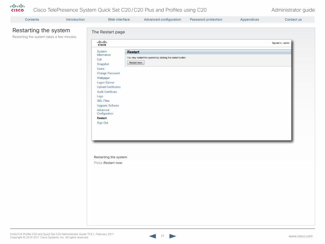
The restart pagerestarting the systemRestarting the system takes a few minutes.
restarting the system
Press Restart now.
28
Cisco TelePresence System Quick Set C20 / C20 Plus and Profiles using C20 Administrator guide
D14637.05 Profile C20 and Quick Set C20 Administrator Guide TC4.1, February 2011. Copyright © 2010-2011 Cisco Systems, Inc. All rights reserved. www.cisco.com
Chapter 3
Advanced configuration settings
29
Cisco TelePresence System Quick Set C20 / C20 Plus and Profiles using C20 Administrator guide
D14637.05 Profile C20 and Quick Set C20 Administrator Guide TC4.1, February 2011. Copyright © 2010-2011 Cisco Systems, Inc. All rights reserved. www.cisco.com
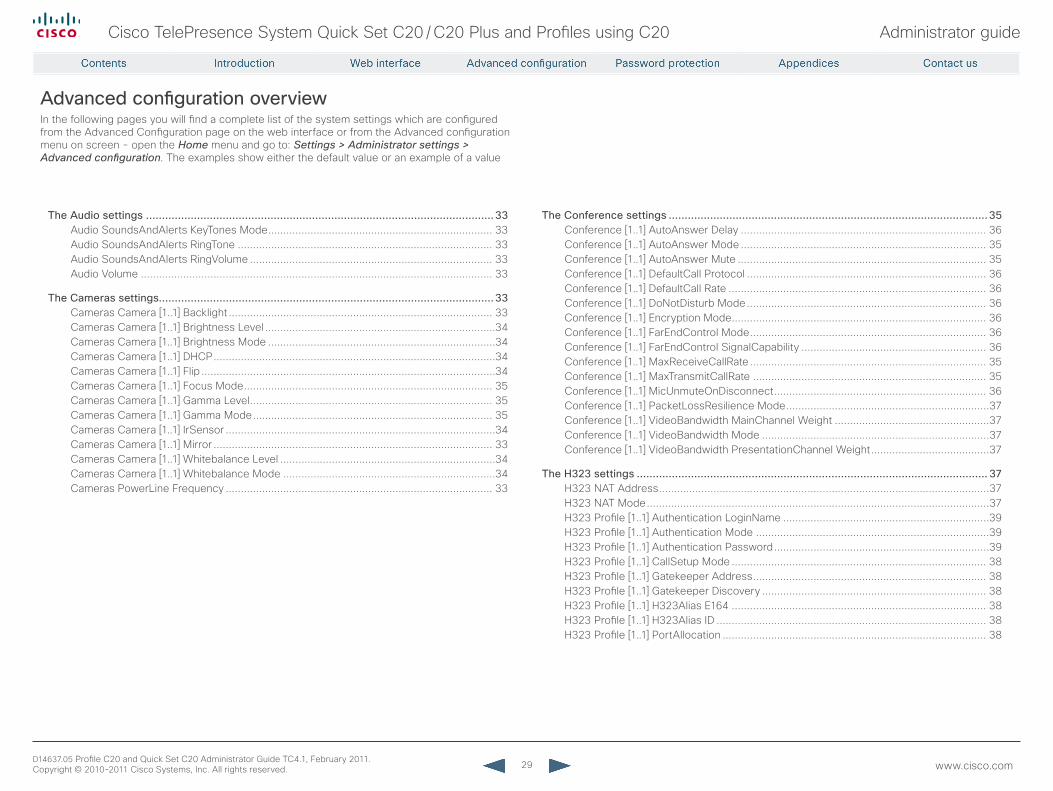
The Audio settings .............................................................................................................33Audio SoundsAndAlerts KeyTones Mode .......................................................................... 33Audio SoundsAndAlerts RingTone .................................................................................... 33Audio SoundsAndAlerts RingVolume ................................................................................ 33Audio Volume .................................................................................................................... 33
The Cameras settings.........................................................................................................33Cameras Camera [1..1] Backlight ....................................................................................... 33Cameras Camera [1..1] Brightness Level ............................................................................34Cameras Camera [1..1] Brightness Mode ...........................................................................34Cameras Camera [1..1] DHCP .............................................................................................34Cameras Camera [1..1] Flip .................................................................................................34Cameras Camera [1..1] Focus Mode .................................................................................. 35Cameras Camera [1..1] Gamma Level ................................................................................ 35Cameras Camera [1..1] Gamma Mode ............................................................................... 35Cameras Camera [1..1] IrSensor .........................................................................................34Cameras Camera [1..1] Mirror ............................................................................................ 33Cameras Camera [1..1] Whitebalance Level .......................................................................34Cameras Camera [1..1] Whitebalance Mode ......................................................................34Cameras PowerLine Frequency ........................................................................................ 33
The Conference settings ....................................................................................................35Conference [1..1] AutoAnswer Delay ................................................................................. 36Conference [1..1] AutoAnswer Mode ................................................................................. 35Conference [1..1] AutoAnswer Mute .................................................................................. 35Conference [1..1] DefaultCall Protocol ............................................................................... 36Conference [1..1] DefaultCall Rate ..................................................................................... 36Conference [1..1] DoNotDisturb Mode ............................................................................... 36Conference [1..1] Encryption Mode .................................................................................... 36Conference [1..1] FarEndControl Mode .............................................................................. 36Conference [1..1] FarEndControl SignalCapability ............................................................. 36Conference [1..1] MaxReceiveCallRate .............................................................................. 35Conference [1..1] MaxTransmitCallRate ............................................................................. 35Conference [1..1] MicUnmuteOnDisconnect ...................................................................... 36Conference [1..1] PacketLossResilience Mode ...................................................................37Conference [1..1] VideoBandwidth MainChannel Weight ...................................................37Conference [1..1] VideoBandwidth Mode ...........................................................................37Conference [1..1] VideoBandwidth PresentationChannel Weight .......................................37
The H323 settings .............................................................................................................. 37H323 NAT Address .............................................................................................................37H323 NAT Mode .................................................................................................................37H323 Profile [1..1] Authentication LoginName ....................................................................39H323 Profile [1..1] Authentication Mode .............................................................................39H323 Profile [1..1] Authentication Password .......................................................................39H323 Profile [1..1] CallSetup Mode .................................................................................... 38H323 Profile [1..1] Gatekeeper Address ............................................................................. 38H323 Profile [1..1] Gatekeeper Discovery .......................................................................... 38H323 Profile [1..1] H323Alias E164 .................................................................................... 38H323 Profile [1..1] H323Alias ID ......................................................................................... 38H323 Profile [1..1] PortAllocation ....................................................................................... 38
Advanced configuration overviewIn the following pages you will find a complete list of the system settings which are configured from the Advanced Configuration page on the web interface or from the Advanced configuration menu on screen - open the Home menu and go to: Settings > Administrator settings > Advanced configuration. The examples show either the default value or an example of a value
30
Cisco TelePresence System Quick Set C20 / C20 Plus and Profiles using C20 Administrator guide
D14637.05 Profile C20 and Quick Set C20 Administrator Guide TC4.1, February 2011. Copyright © 2010-2011 Cisco Systems, Inc. All rights reserved. www.cisco.com
The Network settings ......................................................................................................... 39Network [1..1] Assignment ..................................................................................................39Network [1..1] DNS Domain Name ......................................................................................41Network [1..1] DNS Server [1..5] Address ...........................................................................41Network [1..1] IEEE8021X AnonymousIdentity ....................................................................42Network [1..1] IEEE8021X Eap Md5 .....................................................................................42Network [1..1] IEEE8021X Eap Peap ....................................................................................42Network [1..1] IEEE8021X Eap TTLS ....................................................................................42Network [1..1] IEEE8021X Identity .......................................................................................42Network [1..1] IEEE8021X Mode ..........................................................................................41Network [1..1] IEEE8021X Password ...................................................................................42Network [1..1] IPStack .........................................................................................................39Network [1..1] IPv4 Address ............................................................................................... 40Network [1..1] IPv4 Gateway .............................................................................................. 40Network [1..1] IPv4 SubnetMask ........................................................................................ 40Network [1..1] IPv6 Address ............................................................................................... 40Network [1..1] IPv6 Assignment ......................................................................................... 40Network [1..1] IPv6 DHCPOtions ........................................................................................ 40Network [1..1] IPv6 Gateway .............................................................................................. 40Network [1..1] MTU ..............................................................................................................39Network [1..1] QoS Diffserv Audio ......................................................................................41Network [1..1] QoS Diffserv Data ........................................................................................41Network [1..1] QoS Diffserv Signalling ................................................................................41Network [1..1] QoS Diffserv Video ......................................................................................41Network [1..1] QoS Mode ................................................................................................... 40Network [1..1] RemoteAccess Allow ...................................................................................42Network [1..1] Speed ...........................................................................................................39Network [1..1] TrafficControl Mode .....................................................................................42
The NetworkServices settings ............................................................................................43NetworkServices H323 Mode ........................................................................................... 45NetworkServices HTTP Mode ........................................................................................... 43NetworkServices HTTPS Mode ........................................................................................ 43NetworkServices HTTPS VerifyClientCertificate .............................................................. 44NetworkServices HTTPS VerifyServerCertificate ............................................................. 44NetworkServices Multiway Address .................................................................................. 43NetworkServices Multiway Protocol .................................................................................. 43NetworkServices NTP Address ......................................................................................... 45NetworkServices NTP Mode ............................................................................................. 45NetworkServices SIP Mode .............................................................................................. 45NetworkServices SNMP CommunityName ....................................................................... 44NetworkServices SNMP Host [1..3] Address ..................................................................... 44NetworkServices SNMP Mode .......................................................................................... 44NetworkServices SNMP SystemContact .......................................................................... 44NetworkServices SNMP SystemLocation ......................................................................... 44NetworkServices SSH AllowPublicKey.............................................................................. 43NetworkServices SSH Mode ............................................................................................. 43NetworkServices Telnet Mode .......................................................................................... 43
The Phonebook settings .....................................................................................................46Phonebook Server [1..1] ID ................................................................................................ 46Phonebook Server [1..1] Type ............................................................................................ 46Phonebook Server [1..1] URL ............................................................................................. 46
The Provisioning settings ...................................................................................................46Provisioning ExternalManager Address ..............................................................................47Provisioning ExternalManager Domain ...............................................................................47Provisioning ExternalManager Path ....................................................................................47Provisioning ExternalManager Protocol ..............................................................................47Provisioning HttpMethod ................................................................................................... 46Provisioning LoginName .................................................................................................... 46Provisioning Mode ............................................................................................................. 46Provisioning Password ...................................................................................................... 46
The Security settings .......................................................................................................... 47Security Audit Logging Mode ............................................................................................ 48Security Audit OnError Action ............................................................................................47Security Audit Server Address ...........................................................................................47Security Audit Server Port ..................................................................................................47Security Session InactivityTimeout .................................................................................... 48
31
Cisco TelePresence System Quick Set C20 / C20 Plus and Profiles using C20 Administrator guide
D14637.05 Profile C20 and Quick Set C20 Administrator Guide TC4.1, February 2011. Copyright © 2010-2011 Cisco Systems, Inc. All rights reserved. www.cisco.com
The SerialPort settings .......................................................................................................48SerialPort BaudRate .......................................................................................................... 48SerialPort LoginRequired ................................................................................................... 48SerialPort Mode ................................................................................................................. 48
The SIP settings ................................................................................................................. 49SIP Profile [1..1] Authentication [1..1] LoginName ............................................................... 50SIP Profile [1..1] Authentication [1..1] Password ................................................................. 50SIP Profile [1..1] DefaultTransport ....................................................................................... 49SIP Profile [1..1] Outbound ................................................................................................. 49SIP Profile [1..1] Proxy [1..4] Address ................................................................................. 50SIP Profile [1..1] Proxy [1..4] Discovery ............................................................................... 49SIP Profile [1..1] TlsVerify ................................................................................................... 49SIP Profile [1..1] Type ......................................................................................................... 49SIP Profile [1..1] URI............................................................................................................ 49
The Standby settings ..........................................................................................................50Standby BootAction............................................................................................................51Standby Control ................................................................................................................. 50Standby Delay ................................................................................................................... 50Standby StandbyAction ......................................................................................................51Standby WakeupAction ..................................................................................................... 50
The SystemUnit settings ..................................................................................................... 51SystemUnit CallLogging Mode ...........................................................................................52SystemUnit ContactInfo Type .............................................................................................52SystemUnit IrSensor Mode ................................................................................................51SystemUnit MenuLanguage ...............................................................................................51SystemUnit Name ...............................................................................................................51
The Time settings ............................................................................................................... 52Time DateFormat ............................................................................................................... 53Time TimeFormat .............................................................................................................. 53Time Zone ..........................................................................................................................52
The Video settings ..............................................................................................................53Video AllowWebSnapshots ............................................................................................... 53Video DefaultPresentationSource ..................................................................................... 54Video Input DVI [2] Type .................................................................................................... 56Video Input Source [1..2] CameraControl CameraId ......................................................... 55Video Input Source [1..2] CameraControl Mode ................................................................ 55Video Input Source [1..2] Name ......................................................................................... 54Video Input Source [1..2] OptimalDefinition Profile ............................................................ 55Video Input Source [1..2] OptimalDefinition Threshold60fps ............................................. 56Video Input Source [1..2] Quality ....................................................................................... 55Video Input Source [1..2] Type ........................................................................................... 55Video Input Source 1 Connector ....................................................................................... 54Video Input Source 2 Connector ....................................................................................... 54Video Layout LocalLayoutFamily ........................................................................................57Video Layout RemoteLayoutFamily ....................................................................................57Video Layout ScaleToFrame ...............................................................................................57Video Layout ScaleToFrameThreshold ...............................................................................57Video Layout Scaling ......................................................................................................... 56Video MainVideoSource .................................................................................................... 54Video Monitors .................................................................................................................. 54Video OSD InputMethod Cyrillic ........................................................................................ 58Video OSD InputMethod InputLanguage ........................................................................... 58Video OSD LoginRequired ................................................................................................. 58Video OSD Mode ................................................................................................................57Video OSD MyContactsExpanded .................................................................................... 58Video OSD Output ............................................................................................................. 58Video OSD TodaysBookings ...............................................................................................57Video Output HDMI [1..2] MonitorRole ............................................................................... 56Video Output HDMI [1..2] OverscanLevel .......................................................................... 56Video Output HDMI [1..2] Resolution ................................................................................. 56Video Selfview ................................................................................................................... 53Video SelfviewPosition ...................................................................................................... 53Video WallPaper ................................................................................................................ 54
32
Cisco TelePresence System Quick Set C20 / C20 Plus and Profiles using C20 Administrator guide
D14637.05 Profile C20 and Quick Set C20 Administrator Guide TC4.1, February 2011. Copyright © 2010-2011 Cisco Systems, Inc. All rights reserved. www.cisco.com
The Experimental settings .................................................................................................. 59Experimental CapsetFilter ..................................................................................................59Experimental Conference [1..1] PacketLossResilience ForwardErrorCorrection ................59Experimental Conference [1..1] PacketLossResilience RateAdaption.................................59Experimental CustomSoftbuttons State [1..2] Softbutton [1..5] Type ..................................59Experimental CustomSoftbuttons State [1..2] Softbutton [1..5] Value ................................59Experimental NetworkServices UPnP Mode ......................................................................59Experimental NetworkServices UPnP Timeout ..................................................................59Experimental SoftwareUpgrade Mode ...............................................................................59Experimental SoftwareUpgrade ServerAddress ............................................................... 60Experimental SystemUnit MenuType ................................................................................. 60
33
Cisco TelePresence System Quick Set C20 / C20 Plus and Profiles using C20 Administrator guide
D14637.05 Profile C20 and Quick Set C20 Administrator Guide TC4.1, February 2011. Copyright © 2010-2011 Cisco Systems, Inc. All rights reserved. www.cisco.com
The Audio settings
Audio SoundsAndAlerts KeyTones ModeThe system can produce a sound every time a key on the remote control is pressed.
requires user role: USER
Value space: <On/Off>On: There will be a sound indicator when pressing keys on the remote control.
Off: The key tone on the remote control is switched off.
Example: Audio SoundsAndAlerts KeyTones Mode: Off
Audio SoundsAndAlerts ringToneSelects the ringtone for incoming calls.
requires user role: USER
Value space: <Marbles/IceCrystals/Polaris/Alert/Discreet/Fantasy/Jazz/Nordic/Echo/Rhythmic>
Range: Select a tone from the list of ringtones.
Example: Audio SoundsAndAlerts RingTone: Jazz
Audio SoundsAndAlerts ringVolumeSets the ring tone volume for an incoming call. The value goes in steps of 5 from 0 to 100 (from -34.5dB to 15dB). Volume 0 = Off.
requires user role: USER
Value space: <0..100>Range: Select a value from 0 to 100.
Example: Audio SoundsAndAlerts RingVolume: 50
Audio VolumeSet the volume on the loudspeaker. The value goes in steps of 5 from 0 to 100 (from -34.5dB to 15dB). Volume 0 = Off.
requires user role: USER
Value space: <0..100>Range: Select a value from 0 to 100.
Example: Audio Volume: 70
The Cameras settings
Cameras PowerLine FrequencyApplies to cameras supporting PowerLine frequency anti-flickering, i.e PrecisionHD 1080p cameras.
requires user role: ADMIN
Value space: <Auto/50Hz/60Hz>Auto: Set to Auto to enable power frequency auto detection in the camera.
50Hz/60Hz: Set to 50Hz or 60Hz.
Example: Cameras PowerLine Frequency: Auto
Cameras Camera [1..1] BacklightThe backlight functionality compensates for lights shining directly at the camera (usually the sun entering the window) to avoid a too dark image from the room.
requires user role: ADMIN
Value space: <On/Off>On: Turn on the camera backlight.
Off: Turn off the camera backlight.
Example: Cameras Camera 1 Backlight: Off
Cameras Camera [1..1] MirrorWith Mirror mode (horizontal flip) you can mirror the image on screen.
requires user role: ADMIN
Value space: <Auto/On/Off>Auto: When the camera is placed upside down the image is automatically mirrored. Use this setting with cameras that can be mounted upside down, and that can auto detect that the camera is mounted upside down.
On: See the selfview in mirror mode, e.g. the selfview is reversed and the experience of selfview is as seeing yourself in a mirror.
Off: See the selfview in normal mode, e.g. the experience of selfview is as seeing yourself as other people see you.
Example: Cameras Camera 1 Mirror: Off
34
Cisco TelePresence System Quick Set C20 / C20 Plus and Profiles using C20 Administrator guide
D14637.05 Profile C20 and Quick Set C20 Administrator Guide TC4.1, February 2011. Copyright © 2010-2011 Cisco Systems, Inc. All rights reserved. www.cisco.com
Cameras Camera [1..1] FlipWith Flip mode (vertical flip) you can flip the image upside down.
requires user role: ADMIN
Value space: <Auto/On/Off>Auto: When the camera is placed upside down the image is automatically flipped upside down. Use this setting with cameras that can be mounted upside down, and that can auto detect that the camera is mounted upside down.
On: When set to On the video on screen is flipped. This setting is used with cameras that can be mounted upside down, but cannot auto detect that the camera is mounted upside down.
Off: Set to Off to display the video on screen the normal way.
Example: Cameras Camera 1 Flip: Off
Cameras Camera [1..1] DHCPApplies to cameras which supports DHCP. The Cisco TelePresence PrecsisionHD 1080p camera supports DHCP. The camera must be connected to a LAN. When set, the command enables support for SW upgrade of daisy chained cameras. It will enable the camera's DHCP function and force start of MAC and IP address retrieval. Remember to reset the DHCP when the camera is no longer connected to a LAN.
requires user role: ADMIN
Value space: <On/Off>On: Enable DHCP in the camera. The camera is automatically re-booted. After re-boot the DHCP is started and the IP address will be retrieved. Run the commnand "xStatus Camera" for result.
Off: Set to Off will disable DHCP in the camera. NOTE: When camera is not connected to a LAN, this setting should be applied.
Example: Cameras Camera 1 DHCP: Off
Cameras Camera [1..1] IrSensorThe IR sensor LED is located in the front of the camera and flickers when the IR sensor is activated from the remote control. Both the Codec C Series and PrecisionHD camera have IR sensors, and only one of them needs to be enabled at the time.
requires user role: ADMIN
Value space: <On/Off>On: Enable the IR sensor on the camera.
Off: Disable the IR sensor on the camera.
Example: Cameras Camera 1 IrSensor: On
Cameras Camera [1..1] Brightness ModeSet the camera brightness mode.
requires user role: ADMIN
Value space: <Auto/Manual>Auto: The camera brightness is automatically set by the system.
Manual: Enable manual control of the camera brightness, e.g. the level of the brightness level setting will be used for the camera.
Example: Cameras Camera 1 Brightness Mode: Auto
Cameras Camera [1..1] Brightness LevelSet the brightness level. NOTE: Requires the Camera Brightness Mode to be set to Manual.
requires user role: ADMIN
Value space: <1..31>Range: Select a value from 1 to 31.
Example: Cameras Camera 1 Brightness Level: 1
Cameras Camera [1..1] Whitebalance ModeSet the camera whitebalance mode.
requires user role: ADMIN
Value space: <Auto/Manual>Auto: When set to Auto, the camera will continuously adjust the whitebalance depending on the camera view.
Manual: Set to Manual to enable manual control of the camera whitebalance, e.g. the level of the whitebalance level setting will be used for the camera.
Example: Cameras Camera 1 Whitebalance Mode: auto
Cameras Camera [1..1] Whitebalance LevelSet the whitebalance level. NOTE: Requires the Camera Whitebalance Mode to be set to manual.
requires user role: ADMIN
Value space: <1..16>Range: Select a value from 1 to 16.
Example: Cameras Camera 1 Whitebalance Level: 1
35
Cisco TelePresence System Quick Set C20 / C20 Plus and Profiles using C20 Administrator guide
D14637.05 Profile C20 and Quick Set C20 Administrator Guide TC4.1, February 2011. Copyright © 2010-2011 Cisco Systems, Inc. All rights reserved. www.cisco.com
Cameras Camera [1..1] Focus ModeSet the camera focus mode.
requires user role: ADMIN
Value space: <Auto/Manual>Auto: When set to Auto the focus will be updated throughout the call. When moving the camera, the system will use auto focus for a few seconds to set the right focus of the new camera position. After a few seconds auto focus is turned off to prevent continuous focus adjustments of the camera.
Manual: Turn the autofocus off and adjust the camera focus manually.
Example: Cameras Camera 1 Focus Mode: Auto
Cameras Camera [1..1] Gamma ModeApplies to cameras which supports gamma mode. The Gamma Mode setting enables for gamma corrections. Gamma describes the nonlinear relationship between image pixels and monitor brightness. The Cisco TelePresence PrecisionHD 720p camera supports gamma mode. The PrecisionHD 1080p camera does not support gamma mode.
requires user role: ADMIN
Value space: <Auto/Manual>Auto: Auto is the default and the recommended setting.
Manual: In severe light conditions, you may switch mode to manual and specify explicitly which gamma table to use by setting the Gamma Level.
Example: Cameras Camera 1 Gamma Mode: Auto
Cameras Camera [1..1] Gamma LevelBy setting the Gamma Level you can select which gamma correction table to use. This setting may be useful in difficult lighting conditions, where changes to the brightness setting does not provide satisfactory results. NOTE: Requires the Gamma Mode to be set to Manual.
requires user role: ADMIN
Value space: <0..7>Range: Select a value from 0 to 7.
Example: Cameras Camera 1 Gamma Level: 0
The Conference settings
Conference [1..1] MaxTransmitCallrateSpecify the maximum transmit call rate to be used when placing or receiving calls.
requires user role: ADMIN
Value space: <64..6000>Range: Select a value from 64 to 6000 kbps.
Example: Conference 1 MaxTransmitCallRate: 6000
Conference [1..1] MaxreceiveCallrateSpecify the maximum receive call rate to be used when placing or receiving calls.
requires user role: ADMIN
Value space: <64..6000>Range: Select a value from 64 to 6000 kbps.
Example: Conference 1 MaxReceiveCallRate: 6000
Conference [1..1] AutoAnswer ModeSet the AutoAnswer mode.
requires user role: ADMIN
Value space: <On/Off>On: Enable AutoAnswer to let the system automatically answer all incoming calls.
Off: The incoming calls must be answered manually by pressing the OK key or the green Call key on the remote control.
Example: Conference 1 AutoAnswer Mode: Off
Conference [1..1] AutoAnswer MuteDetermine if the microphone shall be muted when an incoming call is automatically answered. NOTE: Requires the AutoAnswer Mode to be enabled.
requires user role: ADMIN
Value space: <On/Off>On: The incoming call will be muted when automatically answered.
Off: The incoming call will not be muted.
Example: Conference 1 AutoAnswer Mute: Off
36
Cisco TelePresence System Quick Set C20 / C20 Plus and Profiles using C20 Administrator guide
D14637.05 Profile C20 and Quick Set C20 Administrator Guide TC4.1, February 2011. Copyright © 2010-2011 Cisco Systems, Inc. All rights reserved. www.cisco.com
Conference [1..1] AutoAnswer DelayDefine how long (in seconds) an incoming call has to wait before it is answered automatically by the system. NOTE: Requires the AutoAnswer Mode to be enabled.
requires user role: ADMIN
Value space: <0..50>Range: Select a value from 0 to 50 seconds.
Example: Conference 1 AutoAnswer Delay: 0
Conference [1..1] MicUnmuteOnDisconnectDetermine if the microphones should be unmuted automatically when all calls are disconnected. In a meeting room or other shared resource this could be done to prepare the system for the next user.
requires user role: ADMIN
Value space: <On/Off>On: Un-mute the microphones after the call is disconnected.
Off: If muted, let the microphones remain muted after the call is disconnected.
Example: Conference 1 MicUnmuteOnDisconnect: On
Conference [1..1] DoNotDisturb ModeDetermine if there should be an alert on incoming calls.
requires user role: USER
Value space: <On/Off>On: On: All incoming calls will be rejected, with no alert. The calling side will receive a busy signal when trying to call the codec. A message will display on screen, telling that Do not disturb is turned on, together with an option to turn off the Do not disturb. When turning off the Do not disturb mode you will see a list of the calls that have been rejected.
Off: The incoming calls will be alerted.
Example: DoNotDisturb Mode: Off
Conference [1..1] FarEndControl ModeLets you decide if the remote side (far end) should be allowed to select your video sources and control your local camera (pan, tilt, zoom).
requires user role: ADMIN
Value space: <On/Off>On: Set to On when you want the far end to be able to select your video sources and control your local camera (pan, tilt, zoom). You will still be able to control your camera and select your video sources as normal.
Off: When set to Off the far end can not access any of the features above on your system.
Example: Conference 1 FarEndControl Mode: On
Conference [1..1] FarEndControl SignalCapabilitySet the far end control (H.224) signal capability mode.
requires user role: ADMIN
Value space: <On/Off>On: Enable the far end control signal capability.
Off: Disable the far end control signal capability.
Example: Conference 1 FarEndControl SignalCapability: On
Conference [1..1] Encryption ModeSet the conference encryption mode. A padlock with the text "Encryption On" or "Encryption Off" displays on screen, for a few seconds, when the conference starts.
requires user role: ADMIN
Value space: <BestEffort/On/Off>BestEffort: The system will use encryption whenever possible.
> In Point to point calls: If the far end system supports encryption (AES-128), the call will be encrypted. If not, the call will proceed without encryption.
> In MultiSite calls: In order to have encrypted MultiSite conferences, all sites must support encryption. If not, the conference will be unencrypted.
On: The system will only allow calls that are encrypted.
Off: The system will not use encryption.
Example: Conference 1 Encryption Mode: BestEffort
Conference [1..1] DefaultCall ProtocolSet the Default Call Protocol to be used when placing calls from the system.
requires user role: ADMIN
Value space: <H323/SIP>H.323: Select H.323 to ensure that calls are set up as H.323 calls.
SIP: Select SIP to ensure that calls are set up as SIP calls.
Example: Conference 1 DefaultCall Protocol: H323
Conference [1..1] DefaultCall rateSet the Default Call Rate to be used when placing calls from the system.
requires user role: ADMIN
Value space: <64..6000>Range: 64-6000kbps
Example: Conference 1 DefaultCall Rate: 768
37
Cisco TelePresence System Quick Set C20 / C20 Plus and Profiles using C20 Administrator guide
D14637.05 Profile C20 and Quick Set C20 Administrator Guide TC4.1, February 2011. Copyright © 2010-2011 Cisco Systems, Inc. All rights reserved. www.cisco.com
Conference [1..1] VideoBandwidth ModeSet the conference video bandwidth mode.
requires user role: ADMIN
Value space: <Dynamic/Static>Dynamic: The available transmit bandwidth for the video channels are distributed among the currently active channels. If there is no presentation, the main video channels will use the bandwidth of the presentation channel.
Static: The available transmit bandwidth is assigned to each video channel, even if it is not active.
Example: Conference 1 VideoBandwidth Mode: Dynamic
Conference [1..1] VideoBandwidth MainChannel WeightThe available transmit video bandwidth is distributed on the main channel and presentation channel according to "MainChannel Weight" and "PresentationChannel Weight". If the main channel weight is 2 and the presentation channel weight is 1, then the main channel will use twice as much bandwidth as the presentation channel.
requires user role: ADMIN
Value space: <1..10>Range: 1 to 10.
Example: Conference 1 VideoBandwidth MainChannel Weight: 5
Conference [1..1] VideoBandwidth PresentationChannel WeightThe available transmit video bandwidth is distributed on the main channel and presentation channel according to "MainChannel Weight" and "PresentationChannel Weight". If the main channel weight is 2 and the presentation channel weight is 1, then the main channel will use twice as much bandwidth as the presentation channel.
requires user role: ADMIN
Value space: <1..10>Range: 1 to 10.
Example: Conference 1 VideoBandwidth PresentationChannel Weight: 5
Conference [1..1] PacketLossresilience ModeSet the packetloss resilience mode. This configuration will only take effect for calls initiated after the configuration is set.
requires user role: ADMIN
Value space: <On/Off>On: Enable the packetloss resilience.
Off: Disable the packetloss resilience.
Example: Conference 1 PacketLossResilience Mode: On
The H323 settings
H323 NAT ModeThe firewall traversal technology creates a secure path through the firewall barrier, and enables proper exchange of audio/video data when connected to an external video conferencing system (when the IP traffic goes through a NAT router). NOTE: NAT does not work in conjunction with gatekeepers.
requires user role: ADMIN
Value space: <Auto/On/Off>Auto: The system will determine if the "NAT Address" or the real IP-address should be used within signalling. This is done to make it possible to place calls to endpoints on the LAN as well as endpoints on the WAN.
On: The system will signal the configured "NAT Address" in place of its own IP-address within Q.931 and H.245. The NAT Server Address will be shown in the startup-menu as: "My IP Address: 10.0.2.1".
Off: The system will signal the real IP Address.
Example: H323 NAT Mode: Off
H323 NAT AddressEnter the external/global IP-address to the router with NAT support. Packets sent to the router will then be routed to the system.
In the router, the following ports must be routed to the system's IP-address:
* Port 1720
* Port 5555 to 5574
* Port 2326 to 2485
requires user role: ADMIN
Value space: <S: 0, 64>Format: String with a maximum of 64 characters.
Example: H323 NAT Address: ""
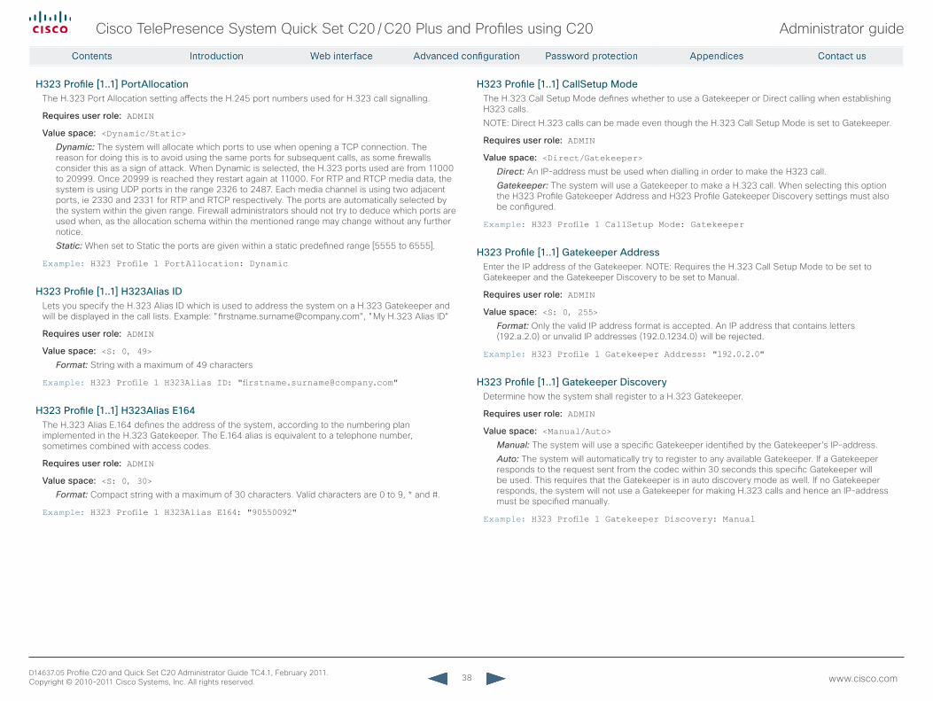
38
Cisco TelePresence System Quick Set C20 / C20 Plus and Profiles using C20 Administrator guide
D14637.05 Profile C20 and Quick Set C20 Administrator Guide TC4.1, February 2011. Copyright © 2010-2011 Cisco Systems, Inc. All rights reserved. www.cisco.com
H323 Profile [1..1] PortAllocationThe H.323 Port Allocation setting affects the H.245 port numbers used for H.323 call signalling.
requires user role: ADMIN
Value space: <Dynamic/Static>Dynamic: The system will allocate which ports to use when opening a TCP connection. The reason for doing this is to avoid using the same ports for subsequent calls, as some firewalls consider this as a sign of attack. When Dynamic is selected, the H.323 ports used are from 11000 to 20999. Once 20999 is reached they restart again at 11000. For RTP and RTCP media data, the system is using UDP ports in the range 2326 to 2487. Each media channel is using two adjacent ports, ie 2330 and 2331 for RTP and RTCP respectively. The ports are automatically selected by the system within the given range. Firewall administrators should not try to deduce which ports are used when, as the allocation schema within the mentioned range may change without any further notice.
Static: When set to Static the ports are given within a static predefined range [5555 to 6555].
Example: H323 Profile 1 PortAllocation: Dynamic
H323 Profile [1..1] H323Alias IDLets you specify the H.323 Alias ID which is used to address the system on a H.323 Gatekeeper and will be displayed in the call lists. Example: "[email protected]", "My H.323 Alias ID"
requires user role: ADMIN
Value space: <S: 0, 49>Format: String with a maximum of 49 characters
Example: H323 Profile 1 H323Alias ID: "[email protected]"
H323 Profile [1..1] H323Alias E164The H.323 Alias E.164 defines the address of the system, according to the numbering plan implemented in the H.323 Gatekeeper. The E.164 alias is equivalent to a telephone number, sometimes combined with access codes.
requires user role: ADMIN
Value space: <S: 0, 30>Format: Compact string with a maximum of 30 characters. Valid characters are 0 to 9, * and #.
Example: H323 Profile 1 H323Alias E164: "90550092"
H323 Profile [1..1] CallSetup ModeThe H.323 Call Setup Mode defines whether to use a Gatekeeper or Direct calling when establishing H323 calls.
NOTE: Direct H.323 calls can be made even though the H.323 Call Setup Mode is set to Gatekeeper.
requires user role: ADMIN
Value space: <Direct/Gatekeeper>Direct: An IP-address must be used when dialling in order to make the H323 call.
Gatekeeper: The system will use a Gatekeeper to make a H.323 call. When selecting this option the H323 Profile Gatekeeper Address and H323 Profile Gatekeeper Discovery settings must also be configured.
Example: H323 Profile 1 CallSetup Mode: Gatekeeper
H323 Profile [1..1] Gatekeeper AddressEnter the IP address of the Gatekeeper. NOTE: Requires the H.323 Call Setup Mode to be set to Gatekeeper and the Gatekeeper Discovery to be set to Manual.
requires user role: ADMIN
Value space: <S: 0, 255>Format: Only the valid IP address format is accepted. An IP address that contains letters (192.a.2.0) or unvalid IP addresses (192.0.1234.0) will be rejected.
Example: H323 Profile 1 Gatekeeper Address: "192.0.2.0"
H323 Profile [1..1] Gatekeeper DiscoveryDetermine how the system shall register to a H.323 Gatekeeper.
requires user role: ADMIN
Value space: <Manual/Auto>Manual: The system will use a specific Gatekeeper identified by the Gatekeeper's IP-address.
Auto: The system will automatically try to register to any available Gatekeeper. If a Gatekeeper responds to the request sent from the codec within 30 seconds this specific Gatekeeper will be used. This requires that the Gatekeeper is in auto discovery mode as well. If no Gatekeeper responds, the system will not use a Gatekeeper for making H.323 calls and hence an IP-address must be specified manually.
Example: H323 Profile 1 Gatekeeper Discovery: Manual
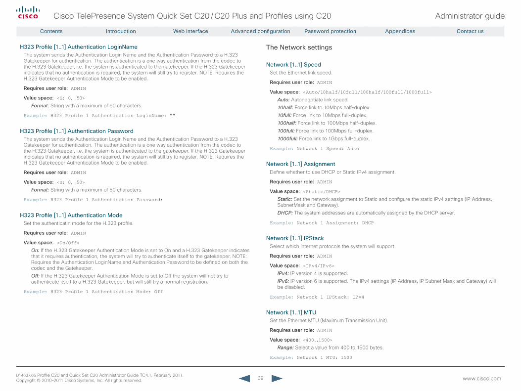
39
Cisco TelePresence System Quick Set C20 / C20 Plus and Profiles using C20 Administrator guide
D14637.05 Profile C20 and Quick Set C20 Administrator Guide TC4.1, February 2011. Copyright © 2010-2011 Cisco Systems, Inc. All rights reserved. www.cisco.com
H323 Profile [1..1] Authentication LoginNameThe system sends the Authentication Login Name and the Authentication Password to a H.323 Gatekeeper for authentication. The authentication is a one way authentication from the codec to the H.323 Gatekeeper, i.e. the system is authenticated to the gatekeeper. If the H.323 Gatekeeper indicates that no authentication is required, the system will still try to register. NOTE: Requires the H.323 Gatekeeper Authentication Mode to be enabled.
requires user role: ADMIN
Value space: <S: 0, 50>Format: String with a maximum of 50 characters.
Example: H323 Profile 1 Authentication LoginName: ""
H323 Profile [1..1] Authentication PasswordThe system sends the Authentication Login Name and the Authentication Password to a H.323 Gatekeeper for authentication. The authentication is a one way authentication from the codec to the H.323 Gatekeeper, i.e. the system is authenticated to the gatekeeper. If the H.323 Gatekeeper indicates that no authentication is required, the system will still try to register. NOTE: Requires the H.323 Gatekeeper Authentication Mode to be enabled.
requires user role: ADMIN
Value space: <S: 0, 50>Format: String with a maximum of 50 characters.
Example: H323 Profile 1 Authentication Password:
H323 Profile [1..1] Authentication ModeSet the authenticatin mode for the H.323 profile.
requires user role: ADMIN
Value space: <On/Off>On: If the H.323 Gatekeeper Authentication Mode is set to On and a H.323 Gatekeeper indicates that it requires authentication, the system will try to authenticate itself to the gatekeeper. NOTE: Requires the Authentication LoginName and Authentication Password to be defined on both the codec and the Gatekeeper.
Off: If the H.323 Gatekeeper Authentication Mode is set to Off the system will not try to authenticate itself to a H.323 Gatekeeper, but will still try a normal registration.
Example: H323 Profile 1 Authentication Mode: Off
The Network settings
Network [1..1] SpeedSet the Ethernet link speed.
requires user role: ADMIN
Value space: <Auto/10half/10full/100half/100full/1000full>Auto: Autonegotiate link speed.
10half: Force link to 10Mbps half-duplex.
10full: Force link to 10Mbps full-duplex.
100half: Force link to 100Mbps half-duplex.
100full: Force link to 100Mbps full-duplex.
1000full: Force link to 1Gbps full-duplex.
Example: Network 1 Speed: Auto
Network [1..1] AssignmentDefine whether to use DHCP or Static IPv4 assignment.
requires user role: ADMIN
Value space: <Static/DHCP>Static: Set the network assignment to Static and configure the static IPv4 settings (IP Address, SubnetMask and Gateway).
DHCP: The system addresses are automatically assigned by the DHCP server.
Example: Network 1 Assignment: DHCP
Network [1..1] IPStackSelect which internet protocols the system will support.
requires user role: ADMIN
Value space: <IPv4/IPv6>IPv4: IP version 4 is supported.
IPv6: IP version 6 is supported. The IPv4 settings (IP Address, IP Subnet Mask and Gateway) will be disabled.
Example: Network 1 IPStack: IPv4
Network [1..1] MTUSet the Ethernet MTU (Maximum Transmission Unit).
requires user role: ADMIN
Value space: <400..1500>Range: Select a value from 400 to 1500 bytes.
Example: Network 1 MTU: 1500
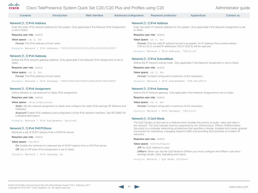
40
Cisco TelePresence System Quick Set C20 / C20 Plus and Profiles using C20 Administrator guide
D14637.05 Profile C20 and Quick Set C20 Administrator Guide TC4.1, February 2011. Copyright © 2010-2011 Cisco Systems, Inc. All rights reserved. www.cisco.com
Network [1..1] IPv6 AddressEnter the static IPv6 network address for the system. Only applicable if the Network IPv6 Assignment is set to Static.
requires user role: ADMIN
Value space: <S: 0, 64>Format: The IPv6 address of host name.
Example: Network 1 IPv6 Address: "ffff:ffff:ffff:ffff:ffff:ffff:ffff:ffff"
Network [1..1] IPv6 GatewayDefine the IPv6 network gateway address. Only applicable if the Network IPv6 Assignment is set to Static.
requires user role: ADMIN
Value space: <S: 0, 64>Format: The IPv6 address of host name.
Example: Network 1 IPv6 Gateway: "ffff:ffff:ffff:ffff:ffff:ffff:ffff:ffff"
Network [1..1] IPv6 AssignmentDefine whether to use Autoconf or Static IPv6 assignment.
requires user role: ADMIN
Value space: <Static/Autoconf>Static: Set the network assignment to Static and configure the static IPv6 settings (IP Address and Gateway).
Autoconf: Enable IPv6 stateless autoconfiguration of the IPv6 network interface. See RFC4862 for a detailed description.
Example: Network 1 IPv6 Assignment: Autoconf
Network [1..1] IPv6 DHCPOtionsRetrieves a set of DHCP options from a DHCPv6 server.
requires user role: ADMIN
Value space: <On/Off>On: Enable the retrieval of a selected set of DHCP options from a DHCPv6 server.
Off: Set to Off when IPv6 Assignment is set to Static.
Example: Network 1 IPv6 Gateway: On
Network [1..1] IPv4 AddressEnter the static IP network address for the system. Only applicable if the Network Assignment is set to Static.
requires user role: ADMIN
Value space: <S: 0, 64>Format: Only the valid IP address format is accepted. An IP address that contains letters (192.a.2.0) or unvalid IP addresses (192.0.1234.0) will be rejected.
Example: Network 1 IPv4 Address: "192.0.2.0"
Network [1..1] IPv4 SubnetMaskDefine the IP network subnet mask. Only applicable if the Network Assignment is set to Static.
requires user role: ADMIN
Value space: <S: 0, 64>Format: Compact string with a maximum of 64 characters.
Example: Network 1 IPv4 SubnetMask: "255.255.255.0"
Network [1..1] IPv4 GatewayDefine the IP network gateway. Only applicable if the Network Assignment is set to Static.
requires user role: ADMIN
Value space: <S: 0, 64>Format: Compact string with a maximum of 64 characters.
Example: Network 1 IPv4 Gateway: "192.0.2.0"
Network [1..1] QoS ModeThe QoS (Quality of Service) is a method which handles the priority of audio, video and data in the network. The QoS settings must be supported by the infrastructure. Diffserv (Differentiated Services) is a computer networking architecture that specifies a simple, scalable and coarse-grained mechanism for classifying, managing network traffic and providing QoS priorities on modern IP networks.
requires user role: ADMIN
Value space: <Off/Diffserv>Off: No QoS method is used.
Diffserv: When you set the QoS Mode to Diffserv you must configure the Diffserv sub menu settings (Audio, Data, Signalling and Video).
Example: Network 1 QoS Mode: diffserv
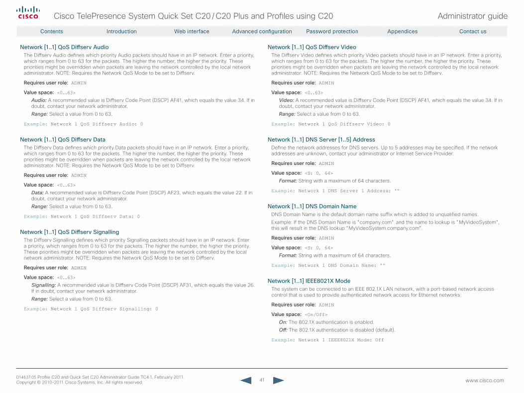
41
Cisco TelePresence System Quick Set C20 / C20 Plus and Profiles using C20 Administrator guide
D14637.05 Profile C20 and Quick Set C20 Administrator Guide TC4.1, February 2011. Copyright © 2010-2011 Cisco Systems, Inc. All rights reserved. www.cisco.com
Network [1..1] QoS Diffserv AudioThe Diffserv Audio defines which priority Audio packets should have in an IP network. Enter a priority, which ranges from 0 to 63 for the packets. The higher the number, the higher the priority. These priorities might be overridden when packets are leaving the network controlled by the local network administrator. NOTE: Requires the Network QoS Mode to be set to Diffserv.
requires user role: ADMIN
Value space: <0..63>Audio: A recommended value is Diffserv Code Point (DSCP) AF41, which equals the value 34. If in doubt, contact your network administrator.
Range: Select a value from 0 to 63.
Example: Network 1 QoS Diffserv Audio: 0
Network [1..1] QoS Diffserv DataThe Diffserv Data defines which priority Data packets should have in an IP network. Enter a priority, which ranges from 0 to 63 for the packets. The higher the number, the higher the priority. These priorities might be overridden when packets are leaving the network controlled by the local network administrator. NOTE: Requires the Network QoS Mode to be set to Diffserv.
requires user role: ADMIN
Value space: <0..63>Data: A recommended value is Diffserv Code Point (DSCP) AF23, which equals the value 22. If in doubt, contact your network administrator.
Range: Select a value from 0 to 63.
Example: Network 1 QoS Diffserv Data: 0
Network [1..1] QoS Diffserv SignallingThe Diffserv Signalling defines which priority Signalling packets should have in an IP network. Enter a priority, which ranges from 0 to 63 for the packets. The higher the number, the higher the priority. These priorities might be overridden when packets are leaving the network controlled by the local network administrator. NOTE: Requires the Network QoS Mode to be set to Diffserv.
requires user role: ADMIN
Value space: <0..63>Signalling: A recommended value is Diffserv Code Point (DSCP) AF31, which equals the value 26. If in doubt, contact your network administrator.
Range: Select a value from 0 to 63.
Example: Network 1 QoS Diffserv Signalling: 0
Network [1..1] QoS Diffserv VideoThe Diffserv Video defines which priority Video packets should have in an IP network. Enter a priority, which ranges from 0 to 63 for the packets. The higher the number, the higher the priority. These priorities might be overridden when packets are leaving the network controlled by the local network administrator. NOTE: Requires the Network QoS Mode to be set to Diffserv.
requires user role: ADMIN
Value space: <0..63>Video: A recommended value is Diffserv Code Point (DSCP) AF41, which equals the value 34. If in doubt, contact your network administrator.
Range: Select a value from 0 to 63.
Example: Network 1 QoS Diffserv Video: 0
Network [1..1] DNS Server [1..5] AddressDefine the network addresses for DNS servers. Up to 5 addresses may be specified. If the network addresses are unknown, contact your administrator or Internet Service Provider.
requires user role: ADMIN
Value space: <S: 0, 64>Format: String with a maximum of 64 characters.
Example: Network 1 DNS Server 1 Address: ""
Network [1..1] DNS Domain NameDNS Domain Name is the default domain name suffix which is added to unqualified names.
Example: If the DNS Domain Name is "company.com" and the name to lookup is "MyVideoSystem", this will result in the DNS lookup "MyVideoSystem.company.com".
requires user role: ADMIN
Value space: <S: 0, 64>Format: String with a maximum of 64 characters.
Example: Network 1 DNS Domain Name: ""
Network [1..1] IEEE8021X ModeThe system can be connected to an IEEE 802.1X LAN network, with a port-based network access control that is used to provide authenticated network access for Ethernet networks.
requires user role: ADMIN
Value space: <On/Off>On: The 802.1X authentication is enabled.
Off: The 802.1X authentication is disabled (default).
Example: Network 1 IEEE8021X Mode: Off
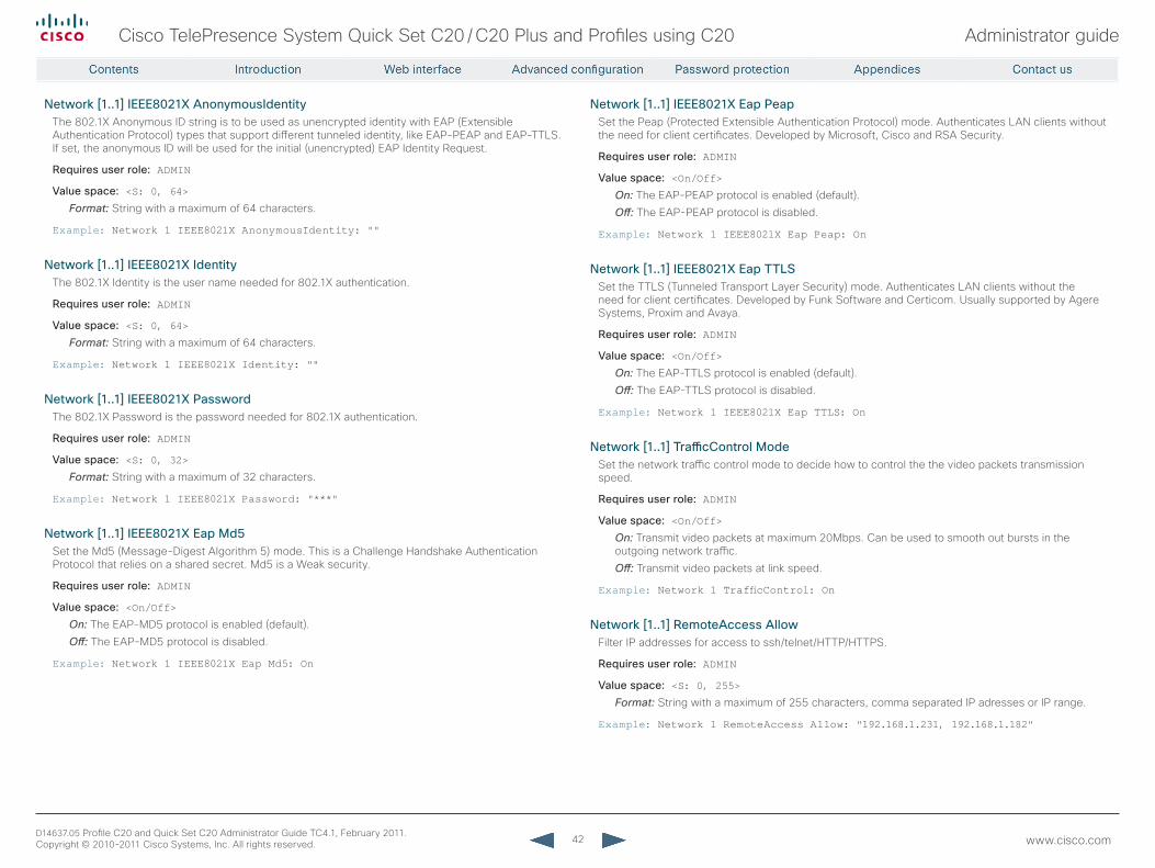
42
Cisco TelePresence System Quick Set C20 / C20 Plus and Profiles using C20 Administrator guide
D14637.05 Profile C20 and Quick Set C20 Administrator Guide TC4.1, February 2011. Copyright © 2010-2011 Cisco Systems, Inc. All rights reserved. www.cisco.com
Network [1..1] IEEE8021X AnonymousIdentityThe 802.1X Anonymous ID string is to be used as unencrypted identity with EAP (Extensible Authentication Protocol) types that support different tunneled identity, like EAP-PEAP and EAP-TTLS. If set, the anonymous ID will be used for the initial (unencrypted) EAP Identity Request.
requires user role: ADMIN
Value space: <S: 0, 64>Format: String with a maximum of 64 characters.
Example: Network 1 IEEE8021X AnonymousIdentity: ""
Network [1..1] IEEE8021X IdentityThe 802.1X Identity is the user name needed for 802.1X authentication.
requires user role: ADMIN
Value space: <S: 0, 64>Format: String with a maximum of 64 characters.
Example: Network 1 IEEE8021X Identity: ""
Network [1..1] IEEE8021X PasswordThe 802.1X Password is the password needed for 802.1X authentication.
requires user role: ADMIN
Value space: <S: 0, 32>Format: String with a maximum of 32 characters.
Example: Network 1 IEEE8021X Password: "***"
Network [1..1] IEEE8021X Eap Md5Set the Md5 (Message-Digest Algorithm 5) mode. This is a Challenge Handshake Authentication Protocol that relies on a shared secret. Md5 is a Weak security.
requires user role: ADMIN
Value space: <On/Off>On: The EAP-MD5 protocol is enabled (default).
Off: The EAP-MD5 protocol is disabled.
Example: Network 1 IEEE8021X Eap Md5: On
Network [1..1] IEEE8021X Eap PeapSet the Peap (Protected Extensible Authentication Protocol) mode. Authenticates LAN clients without the need for client certificates. Developed by Microsoft, Cisco and RSA Security.
requires user role: ADMIN
Value space: <On/Off>On: The EAP-PEAP protocol is enabled (default).
Off: The EAP-PEAP protocol is disabled.
Example: Network 1 IEEE8021X Eap Peap: On
Network [1..1] IEEE8021X Eap TTLSSet the TTLS (Tunneled Transport Layer Security) mode. Authenticates LAN clients without the need for client certificates. Developed by Funk Software and Certicom. Usually supported by Agere Systems, Proxim and Avaya.
requires user role: ADMIN
Value space: <On/Off>On: The EAP-TTLS protocol is enabled (default).
Off: The EAP-TTLS protocol is disabled.
Example: Network 1 IEEE8021X Eap TTLS: On
Network [1..1] TrafficControl ModeSet the network traffic control mode to decide how to control the the video packets transmission speed.
requires user role: ADMIN
Value space: <On/Off>On: Transmit video packets at maximum 20Mbps. Can be used to smooth out bursts in the outgoing network traffic.
Off: Transmit video packets at link speed.
Example: Network 1 TrafficControl: On
Network [1..1] remoteAccess AllowFilter IP addresses for access to ssh/telnet/HTTP/HTTPS.
requires user role: ADMIN
Value space: <S: 0, 255>Format: String with a maximum of 255 characters, comma separated IP adresses or IP range.
Example: Network 1 RemoteAccess Allow: "192.168.1.231, 192.168.1.182"
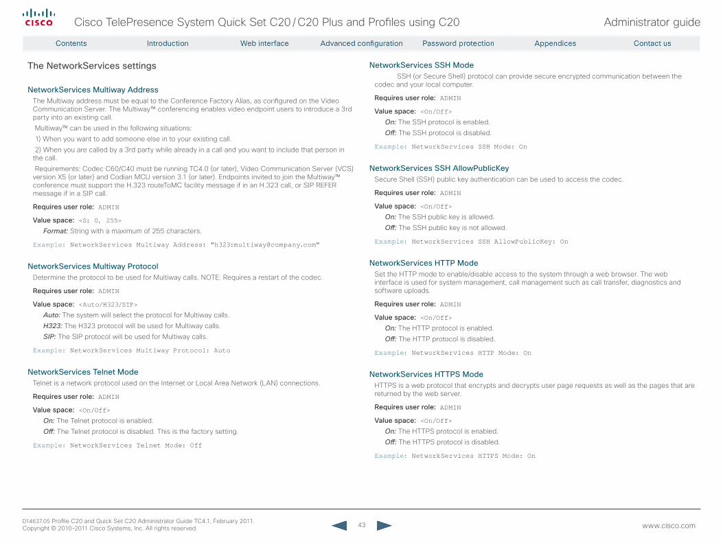
43
Cisco TelePresence System Quick Set C20 / C20 Plus and Profiles using C20 Administrator guide
D14637.05 Profile C20 and Quick Set C20 Administrator Guide TC4.1, February 2011. Copyright © 2010-2011 Cisco Systems, Inc. All rights reserved. www.cisco.com
NetworkServices SSH Mode SSH (or Secure Shell) protocol can provide secure encrypted communication between the codec and your local computer.
requires user role: ADMIN
Value space: <On/Off>On: The SSH protocol is enabled.
Off: The SSH protocol is disabled.
Example: NetworkServices SSH Mode: On
NetworkServices SSH AllowPublicKeySecure Shell (SSH) public key authentication can be used to access the codec.
requires user role: ADMIN
Value space: <On/Off>On: The SSH public key is allowed.
Off: The SSH public key is not allowed.
Example: NetworkServices SSH AllowPublicKey: On
NetworkServices HTTP ModeSet the HTTP mode to enable/disable access to the system through a web browser. The web interface is used for system management, call management such as call transfer, diagnostics and software uploads.
requires user role: ADMIN
Value space: <On/Off>On: The HTTP protocol is enabled.
Off: The HTTP protocol is disabled.
Example: NetworkServices HTTP Mode: On
NetworkServices HTTPS ModeHTTPS is a web protocol that encrypts and decrypts user page requests as well as the pages that are returned by the web server.
requires user role: ADMIN
Value space: <On/Off>On: The HTTPS protocol is enabled.
Off: The HTTPS protocol is disabled.
Example: NetworkServices HTTPS Mode: On
The NetworkServices settings
NetworkServices Multiway AddressThe Multiway address must be equal to the Conference Factory Alias, as configured on the Video Communication Server. The Multiway™ conferencing enables video endpoint users to introduce a 3rd party into an existing call.
Multiway™ can be used in the following situations:
1) When you want to add someone else in to your existing call.
2) When you are called by a 3rd party while already in a call and you want to include that person in the call.
Requirements: Codec C60/C40 must be running TC4.0 (or later), Video Communication Server (VCS) version X5 (or later) and Codian MCU version 3.1 (or later). Endpoints invited to join the Multiway™ conference must support the H.323 routeToMC facility message if in an H.323 call, or SIP REFER message if in a SIP call.
requires user role: ADMIN
Value space: <S: 0, 255>Format: String with a maximum of 255 characters.
Example: NetworkServices Multiway Address: "h323:[email protected]"
NetworkServices Multiway ProtocolDetermine the protocol to be used for Multiway calls. NOTE: Requires a restart of the codec.
requires user role: ADMIN
Value space: <Auto/H323/SIP>Auto: The system will select the protocol for Multiway calls.
H323: The H323 protocol will be used for Multiway calls.
SIP: The SIP protocol will be used for Multiway calls.
Example: NetworkServices Multiway Protocol: Auto
NetworkServices Telnet ModeTelnet is a network protocol used on the Internet or Local Area Network (LAN) connections.
requires user role: ADMIN
Value space: <On/Off>On: The Telnet protocol is enabled.
Off: The Telnet protocol is disabled. This is the factory setting.
Example: NetworkServices Telnet Mode: Off
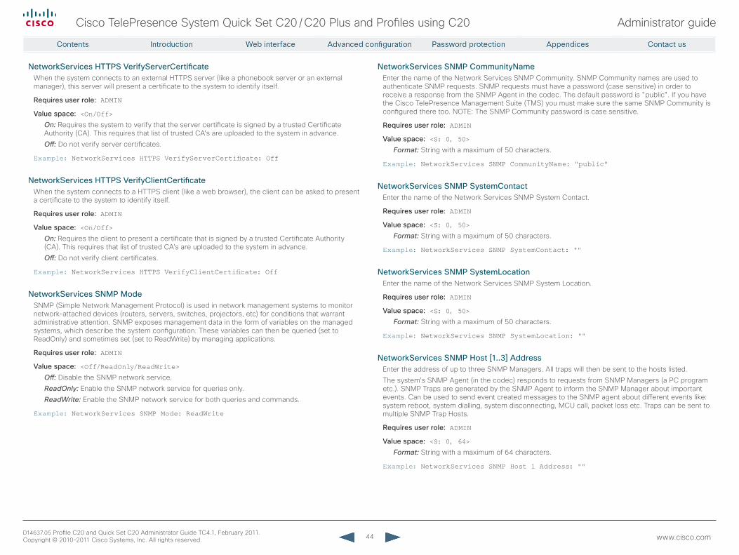
44
Cisco TelePresence System Quick Set C20 / C20 Plus and Profiles using C20 Administrator guide
D14637.05 Profile C20 and Quick Set C20 Administrator Guide TC4.1, February 2011. Copyright © 2010-2011 Cisco Systems, Inc. All rights reserved. www.cisco.com
NetworkServices HTTPS VerifyServerCertificateWhen the system connects to an external HTTPS server (like a phonebook server or an external manager), this server will present a certificate to the system to identify itself.
requires user role: ADMIN
Value space: <On/Off>On: Requires the system to verify that the server certificate is signed by a trusted Certificate Authority (CA). This requires that list of trusted CA's are uploaded to the system in advance.
Off: Do not verify server certificates.
Example: NetworkServices HTTPS VerifyServerCertificate: Off
NetworkServices HTTPS VerifyClientCertificateWhen the system connects to a HTTPS client (like a web browser), the client can be asked to present a certificate to the system to identify itself.
requires user role: ADMIN
Value space: <On/Off>On: Requires the client to present a certificate that is signed by a trusted Certificate Authority (CA). This requires that list of trusted CA's are uploaded to the system in advance.
Off: Do not verify client certificates.
Example: NetworkServices HTTPS VerifyClientCertificate: Off
NetworkServices SNMP ModeSNMP (Simple Network Management Protocol) is used in network management systems to monitor network-attached devices (routers, servers, switches, projectors, etc) for conditions that warrant administrative attention. SNMP exposes management data in the form of variables on the managed systems, which describe the system configuration. These variables can then be queried (set to ReadOnly) and sometimes set (set to ReadWrite) by managing applications.
requires user role: ADMIN
Value space: <Off/ReadOnly/ReadWrite>Off: Disable the SNMP network service.
ReadOnly: Enable the SNMP network service for queries only.
ReadWrite: Enable the SNMP network service for both queries and commands.
Example: NetworkServices SNMP Mode: ReadWrite
NetworkServices SNMP CommunityNameEnter the name of the Network Services SNMP Community. SNMP Community names are used to authenticate SNMP requests. SNMP requests must have a password (case sensitive) in order to receive a response from the SNMP Agent in the codec. The default password is "public". If you have the Cisco TelePresence Management Suite (TMS) you must make sure the same SNMP Community is configured there too. NOTE: The SNMP Community password is case sensitive.
requires user role: ADMIN
Value space: <S: 0, 50>Format: String with a maximum of 50 characters.
Example: NetworkServices SNMP CommunityName: "public"
NetworkServices SNMP SystemContactEnter the name of the Network Services SNMP System Contact.
requires user role: ADMIN
Value space: <S: 0, 50>Format: String with a maximum of 50 characters.
Example: NetworkServices SNMP SystemContact: ""
NetworkServices SNMP SystemLocationEnter the name of the Network Services SNMP System Location.
requires user role: ADMIN
Value space: <S: 0, 50>Format: String with a maximum of 50 characters.
Example: NetworkServices SNMP SystemLocation: ""
NetworkServices SNMP Host [1..3] AddressEnter the address of up to three SNMP Managers. All traps will then be sent to the hosts listed.
The system's SNMP Agent (in the codec) responds to requests from SNMP Managers (a PC program etc.). SNMP Traps are generated by the SNMP Agent to inform the SNMP Manager about important events. Can be used to send event created messages to the SNMP agent about different events like: system reboot, system dialling, system disconnecting, MCU call, packet loss etc. Traps can be sent to multiple SNMP Trap Hosts.
requires user role: ADMIN
Value space: <S: 0, 64>Format: String with a maximum of 64 characters.
Example: NetworkServices SNMP Host 1 Address: ""
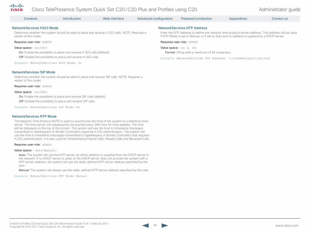
45
Cisco TelePresence System Quick Set C20 / C20 Plus and Profiles using C20 Administrator guide
D14637.05 Profile C20 and Quick Set C20 Administrator Guide TC4.1, February 2011. Copyright © 2010-2011 Cisco Systems, Inc. All rights reserved. www.cisco.com
NetworkServices H323 ModeDetermine whether the system should be able to place and receive H.323 calls. NOTE: Requires a restart of the codec.
requires user role: ADMIN
Value space: <On/Off>On: Enable the possibility to place and receive H.323 calls (default).
Off: Disable the possibility to place and receive H.323 calls.
Example: NetworkServices H323 Mode: On
NetworkServices SIP ModeDetermine whether the system should be able to place and receive SIP calls. NOTE: Requires a restart of the codec.
requires user role: ADMIN
Value space: <On/Off>On: Enable the possibility to place and receive SIP calls (default).
Off: Disable the possibility to place and receive SIP calls.
Example: NetworkServices SIP Mode: On
NetworkServices NTP ModeThe Network Time Protocol (NTP) is used to synchronize the time of the system to a reference time server. The time server will subsequently be queried every 24th hour for time updates. The time will be displayed on the top of the screen. The system will use the time to timestamp messages transmitted to Gatekeepers or Border Controllers requiring H.235 authentication. The system will use the time to timestamp messages transmitted to Gatekeepers or Border Controllers that requires H.235 authentication. It is also used for timestamping Placed Calls, Missed Calls and Received Calls.
requires user role: ADMIN
Value space: <Auto/Manual>Auto: The system will use the NTP server, by which address is supplied from the DHCP server in the network. If no DHCP server is used, or the DHCP server does not provide the system with a NTP server address, the system will use the static defined NTP server address specified by the user.
Manual: The system will always use the static defined NTP server address specified by the user.
Example: NetworkServices NTP Mode: Manual
NetworkServices NTP AddressEnter the NTP Address to define the network time protocol server address. This address will be used if NTP Mode is set to Manual, or if set to Auto and no address is supplied by a DHCP server.
requires user role: ADMIN
Value space: <S: 0, 64>Format: String with a maximum of 64 characters.
Example: NetworkServices NTP Address: "1.tandberg.pool.ntp.org"
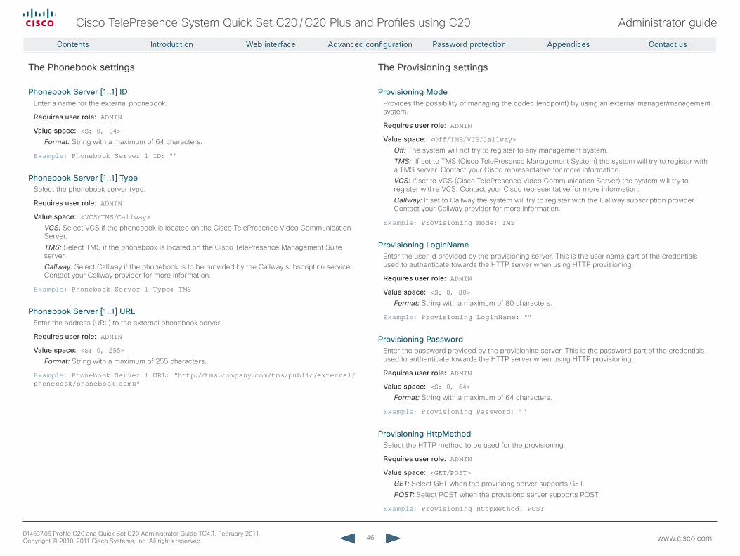
46
Cisco TelePresence System Quick Set C20 / C20 Plus and Profiles using C20 Administrator guide
D14637.05 Profile C20 and Quick Set C20 Administrator Guide TC4.1, February 2011. Copyright © 2010-2011 Cisco Systems, Inc. All rights reserved. www.cisco.com
The Phonebook settings
Phonebook Server [1..1] IDEnter a name for the external phonebook.
requires user role: ADMIN
Value space: <S: 0, 64>Format: String with a maximum of 64 characters.
Example: Phonebook Server 1 ID: ""
Phonebook Server [1..1] TypeSelect the phonebook server type.
requires user role: ADMIN
Value space: <VCS/TMS/Callway>VCS: Select VCS if the phonebook is located on the Cisco TelePresence Video Communication Server.
TMS: Select TMS if the phonebook is located on the Cisco TelePresence Management Suite server.
Callway: Select Callway if the phonebook is to be provided by the Callway subscription service. Contact your Callway provider for more information.
Example: Phonebook Server 1 Type: TMS
Phonebook Server [1..1] UrLEnter the address (URL) to the external phonebook server.
requires user role: ADMIN
Value space: <S: 0, 255>Format: String with a maximum of 255 characters.
Example: Phonebook Server 1 URL: "http://tms.company.com/tms/public/external/phonebook/phonebook.asmx"
The Provisioning settings
Provisioning ModeProvides the possibility of managing the codec (endpoint) by using an external manager/management system.
requires user role: ADMIN
Value space: <Off/TMS/VCS/Callway>Off: The system will not try to register to any management system.
TMS: If set to TMS (Cisco TelePresence Management System) the system will try to register with a TMS server. Contact your Cisco representative for more information.
VCS: If set to VCS (Cisco TelePresence Video Communication Server) the system will try to register with a VCS. Contact your Cisco representative for more information.
Callway: If set to Callway the system will try to register with the Callway subscription provider. Contact your Callway provider for more information.
Example: Provisioning Mode: TMS
Provisioning LoginNameEnter the user id provided by the provisioning server. This is the user name part of the credentials used to authenticate towards the HTTP server when using HTTP provisioning.
requires user role: ADMIN
Value space: <S: 0, 80>Format: String with a maximum of 80 characters.
Example: Provisioning LoginName: ""
Provisioning PasswordEnter the password provided by the provisioning server. This is the password part of the credentials used to authenticate towards the HTTP server when using HTTP provisioning.
requires user role: ADMIN
Value space: <S: 0, 64>Format: String with a maximum of 64 characters.
Example: Provisioning Password: ""
Provisioning HttpMethodSelect the HTTP method to be used for the provisioning.
requires user role: ADMIN
Value space: <GET/POST>GET: Select GET when the provisiong server supports GET.
POST: Select POST when the provisiong server supports POST.
Example: Provisioning HttpMethod: POST
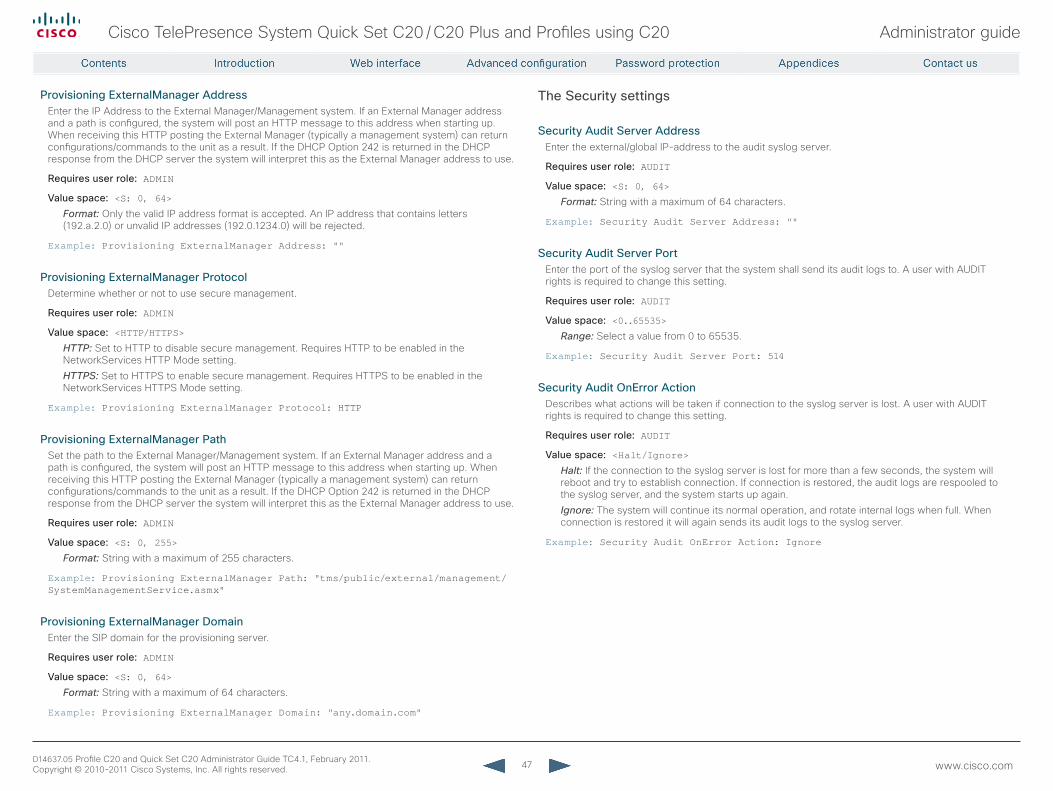
47
Cisco TelePresence System Quick Set C20 / C20 Plus and Profiles using C20 Administrator guide
D14637.05 Profile C20 and Quick Set C20 Administrator Guide TC4.1, February 2011. Copyright © 2010-2011 Cisco Systems, Inc. All rights reserved. www.cisco.com
Provisioning ExternalManager AddressEnter the IP Address to the External Manager/Management system. If an External Manager address and a path is configured, the system will post an HTTP message to this address when starting up. When receiving this HTTP posting the External Manager (typically a management system) can return configurations/commands to the unit as a result. If the DHCP Option 242 is returned in the DHCP response from the DHCP server the system will interpret this as the External Manager address to use.
requires user role: ADMIN
Value space: <S: 0, 64>Format: Only the valid IP address format is accepted. An IP address that contains letters (192.a.2.0) or unvalid IP addresses (192.0.1234.0) will be rejected.
Example: Provisioning ExternalManager Address: ""
Provisioning ExternalManager ProtocolDetermine whether or not to use secure management.
requires user role: ADMIN
Value space: <HTTP/HTTPS>HTTP: Set to HTTP to disable secure management. Requires HTTP to be enabled in the NetworkServices HTTP Mode setting.
HTTPS: Set to HTTPS to enable secure management. Requires HTTPS to be enabled in the NetworkServices HTTPS Mode setting.
Example: Provisioning ExternalManager Protocol: HTTP
Provisioning ExternalManager PathSet the path to the External Manager/Management system. If an External Manager address and a path is configured, the system will post an HTTP message to this address when starting up. When receiving this HTTP posting the External Manager (typically a management system) can return configurations/commands to the unit as a result. If the DHCP Option 242 is returned in the DHCP response from the DHCP server the system will interpret this as the External Manager address to use.
requires user role: ADMIN
Value space: <S: 0, 255>Format: String with a maximum of 255 characters.
Example: Provisioning ExternalManager Path: "tms/public/external/management/SystemManagementService.asmx"
Provisioning ExternalManager DomainEnter the SIP domain for the provisioning server.
requires user role: ADMIN
Value space: <S: 0, 64>Format: String with a maximum of 64 characters.
Example: Provisioning ExternalManager Domain: "any.domain.com"
The Security settings
Security Audit Server AddressEnter the external/global IP-address to the audit syslog server.
requires user role: AUDIT
Value space: <S: 0, 64>Format: String with a maximum of 64 characters.
Example: Security Audit Server Address: ""
Security Audit Server PortEnter the port of the syslog server that the system shall send its audit logs to. A user with AUDIT rights is required to change this setting.
requires user role: AUDIT
Value space: <0..65535>Range: Select a value from 0 to 65535.
Example: Security Audit Server Port: 514
Security Audit OnError ActionDescribes what actions will be taken if connection to the syslog server is lost. A user with AUDIT rights is required to change this setting.
requires user role: AUDIT
Value space: <Halt/Ignore>Halt: If the connection to the syslog server is lost for more than a few seconds, the system will reboot and try to establish connection. If connection is restored, the audit logs are respooled to the syslog server, and the system starts up again.
Ignore: The system will continue its normal operation, and rotate internal logs when full. When connection is restored it will again sends its audit logs to the syslog server.
Example: Security Audit OnError Action: Ignore
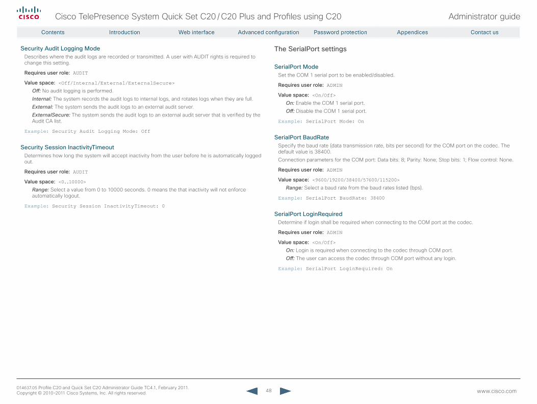
48
Cisco TelePresence System Quick Set C20 / C20 Plus and Profiles using C20 Administrator guide
D14637.05 Profile C20 and Quick Set C20 Administrator Guide TC4.1, February 2011. Copyright © 2010-2011 Cisco Systems, Inc. All rights reserved. www.cisco.com
Security Audit Logging ModeDescribes where the audit logs are recorded or transmitted. A user with AUDIT rights is required to change this setting.
requires user role: AUDIT
Value space: <Off/Internal/External/ExternalSecure>Off: No audit logging is performed.
Internal: The system records the audit logs to internal logs, and rotates logs when they are full.
External: The system sends the audit logs to an external audit server.
ExternalSecure: The system sends the audit logs to an external audit server that is verified by the Audit CA list.
Example: Security Audit Logging Mode: Off
Security Session InactivityTimeoutDetermines how long the system will accept inactivity from the user before he is automatically logged out.
requires user role: AUDIT
Value space: <0..10000>Range: Select a value from 0 to 10000 seconds. 0 means the that inactivity will not enforce automatically logout.
Example: Security Session InactivityTimeout: 0
The SerialPort settings
SerialPort ModeSet the COM 1 serial port to be enabled/disabled.
requires user role: ADMIN
Value space: <On/Off>On: Enable the COM 1 serial port.
Off: Disable the COM 1 serial port.
Example: SerialPort Mode: On
SerialPort BaudrateSpecify the baud rate (data transmission rate, bits per second) for the COM port on the codec. The default value is 38400.
Connection parameters for the COM port: Data bits: 8; Parity: None; Stop bits: 1; Flow control: None.
requires user role: ADMIN
Value space: <9600/19200/38400/57600/115200>Range: Select a baud rate from the baud rates listed (bps).
Example: SerialPort BaudRate: 38400
SerialPort LoginrequiredDetermine if login shall be required when connecting to the COM port at the codec.
requires user role: ADMIN
Value space: <On/Off>On: Login is required when connecting to the codec through COM port.
Off: The user can access the codec through COM port without any login.
Example: SerialPort LoginRequired: On
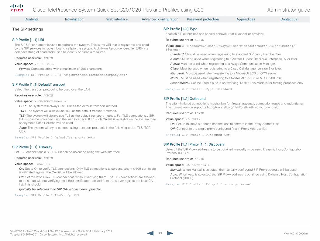
49
Cisco TelePresence System Quick Set C20 / C20 Plus and Profiles using C20 Administrator guide
D14637.05 Profile C20 and Quick Set C20 Administrator Guide TC4.1, February 2011. Copyright © 2010-2011 Cisco Systems, Inc. All rights reserved. www.cisco.com
The SIP settings
SIP Profile [1..1] UrIThe SIP URI or number is used to address the system. This is the URI that is registered and used by the SIP services to route inbound calls to the system. A Uniform Resource Identifier (URI) is a compact string of characters used to identify or name a resource.
requires user role: ADMIN
Value space: <S: 0, 255>Format: Compact string with a maximum of 255 characters.
Example: SIP Profile 1 URI: "sip:[email protected]"
SIP Profile [1..1] DefaultTransportSelect the transport protocol to be used over the LAN.
requires user role: ADMIN
Value space: <UDP/TCP/TLS/Auto>UDP: The system will always use UDP as the default transport method.
TCP: The system will always use TCP as the default transport method.
TLS: The system will always use TLS as the default transport method. For TLS connections a SIP CA-list can be uploaded using the web interface. If no such CA-list is available on the system then anonymous Diffie Hellman will be used.
Auto: The system will try to connect using transport protocols in the following order: TLS, TCP, UDP.
Example: SIP Profile 1 DefaultTransport: Auto
SIP Profile [1..1] TlsVerifyFor TLS connections a SIP CA-list can be uploaded using the web interface.
requires user role: ADMIN
Value space: <On/Off>On: Set to On to verify TLS connections. Only TLS connections to servers, whom x.509 certificate is validated against the CA-list, will be allowed.
Off: Set to Off to allow TLS connections without verifying them. The TLS connections are allowed to be set up without verifying the x.509 certificate received from the server against the local CA-list. This should
typically be selected if no SIP CA-list has been uploaded.
Example: SIP Profile 1 TlsVerify: Off
SIP Profile [1..1] TypeEnables SIP extensions and special behaviour for a vendor or provider.
requires user role: ADMIN
Value space: <Standard/Alcatel/Avaya/Cisco/Microsoft/Nortel/Experimental/Siemens>
Standard: Should be used when registering to standard SIP proxy like OpenSer.
Alcatel: Must be used when registering to a Alcatel-Lucent OmniPCX Enterprise R7 or later.
Avaya: Must be used when registering to a Avaya Communication Manager.
Cisco: Must be used when registering to a Cisco CallManager version 5 or later.
Microsoft: Must be used when registering to a Microsoft LCS or OCS server.
Nortel: Must be used when registering to a Nortel MCS 5100 or MCS 5200 PBX.
Experimental: Can be used if auto is not working. NOTE: This mode is for testing purposes only.
Example: SIP Profile 1 Type: Standard
SIP Profile [1..1] OutboundThe client initiated connections mechanism for firewall traversal, connection reuse and redundancy. The current version supports http://tools.ietf.org/html/draft-ietf-sip-outbound-20.
requires user role: ADMIN
Value space: <On/Off>On: Set up multiple outbound connections to servers in the Proxy Address list.
Off: Connect to the single proxy configured first in Proxy Address list.
Example: SIP Profile 1 Outbound: Off
SIP Profile [1..1] Proxy [1..4] DiscoverySelect if the SIP Proxy address is to be obtained manually or by using Dynamic Host Configuration Protocol (DHCP).
requires user role: ADMIN
Value space: <Auto/Manual>Manual: When Manual is selected, the manually configured SIP Proxy address will be used.
Auto: When Auto is selected, the SIP Proxy address is obtained using Dynamic Host Configuration Protocol (DHCP).
Example: SIP Profile 1 Proxy 1 Discovery: Manual
50
Cisco TelePresence System Quick Set C20 / C20 Plus and Profiles using C20 Administrator guide
D14637.05 Profile C20 and Quick Set C20 Administrator Guide TC4.1, February 2011. Copyright © 2010-2011 Cisco Systems, Inc. All rights reserved. www.cisco.com
SIP Profile [1..1] Proxy [1..4] AddressThe Proxy Address is the manually configured address for the outbound proxy. It is possible to use a fully qualified domain name, or an IP address. The default port is 5060 for TCP and UDP but another one can be provided. If Outbound is enabled, multiple proxies can be addressed.
requires user role: ADMIN
Value space: <S: 0, 255>Format: Compact string with a maximum of 255 characters. An IP address that contains letters (192.a.2.0) or unvalid IP addresses (192.0.1234.0) will be rejected.
Example: SIP Profile 1 Proxy 1 Address: ""
SIP Profile [1..1] Authentication [1..1] LoginNameThis is the user name part of the credentials used to authenticate towards the SIP proxy.
requires user role: ADMIN
Value space: <S: 0, 50>Format: String with a maximum of 50 characters.
Example: SIP Profile 1 Authentication 1 LoginName: ""
SIP Profile [1..1] Authentication [1..1] PasswordThis is the password part of the credentials used to authenticate towards the SIP proxy.
requires user role: ADMIN
Value space: <S: 0, 50>Format: String with a maximum of 50 characters.
Example: SIP Profile 1 Authentication 1 Password:
The Standby settings
Standby ControlDetermine whether the system should go into standby mode or not.
requires user role: ADMIN
Value space: <On/Off>On: Enter standby mode when the Standby Delay has timed out. NOTE: Requires the Standby Delay to be set to an appropriate value.
Off: The system will not enter standby mode.
Example: Standby Control: On
Standby DelayDefine how long (in minutes) the system shall be in idle mode before it goes into standby mode. NOTE: Requires the Standby Control to be enabled.
requires user role: ADMIN
Value space: <1..480>Range: Select a value from 1 to 480 minutes.
Example: Standby Delay: 10
Standby WakeupActionDefine the camera position when leaving standby mode.
requires user role: ADMIN
Value space: <None/Preset1/Preset2/Preset3/Preset4/Preset5/Preset6/Preset7/Preset8/Preset9/Preset10/Preset11/Preset12/Preset13/Preset14/Preset15/RestoreCameraPosition/DefaultCameraPosition>
None: No action.
Preset1 to Preset15: When leaving standby the camera position will be set to the position defined by the selected preset.
RestoreCameraPosition: When leaving standby the camera position will be set to the position it had before entering standby.
DefaultCameraPosition: When leaving standby the camera position will be set to the factory default position.
Example: Standby WakeupAction: RestoreCameraPosition
51
Cisco TelePresence System Quick Set C20 / C20 Plus and Profiles using C20 Administrator guide
D14637.05 Profile C20 and Quick Set C20 Administrator Guide TC4.1, February 2011. Copyright © 2010-2011 Cisco Systems, Inc. All rights reserved. www.cisco.com
Standby BootActionDefine the camera position after a restart of the codec.
requires user role: ADMIN
Value space: <None/Preset1/Preset2/Preset3/Preset4/Preset5/Preset6/Preset7/Preset8/Preset9/Preset10/Preset11/Preset12/Preset13/Preset14/Preset15/RestoreCameraPosition/DefaultCameraPosition>
None: No action.
Preset1 to Preset15: After a reboot the camera position will be set to the position defined by the selected preset.
RestoreCameraPosition: After a reboot the camera position will be set to the position it had before the last boot.
DefaultCameraPosition: After a reboot the camera position will be set to the factory default position.
Example: Standby BootAction: DefaultCameraPosition
Standby StandbyActionDefine the camera position when going into standby mode.
requires user role: ADMIN
Value space: <None/PrivacyPosition>None: No action.
PrivacyPosition: Turns the camera to a sideways position for privacy.
Example: Standby StandbyAction: PrivacyPosition
The SystemUnit settings
SystemUnit NameEnter a System Name to define a name of the system unit. If the H.323 Alias ID is configured on the system then this ID will be used instead of the system name. The system name will be displayed:
1) When the codec is acting as an SNMP Agent.
2) Towards a DHCP server.
requires user role: ADMIN
Value space: <S: 0, 50>Format: String with a maximum of 50 characters.
Example: SystemUnit Name: "Meeting Room"
SystemUnit MenuLanguageSelect the language to be used in the menus on screen.
requires user role: USER
Value space: <English/ChineseSimplified/ChineseTraditional/Danish/Dutch/Finnish/French/German/Italian/Japanese/Korean/Norwegian/Polish/PortugueseBrazilian/Russian/Spanish/SpanishLatinAmerican/Swedish/Turkish>
Example: SystemUnit MenuLanguage: English
SystemUnit IrSensor ModeBoth the Codec C Series and PrecisionHD camera have IR sensors, and only one of them needs to be enabled at the time. The IR sensor LED is located on the front of the codec and the camera and flickers when an IR signal is received from the remote control.
requires user role: ADMIN
Value space: <On/Off/Auto>On: Enable the IR sensor on the codec.
Off: Disable the IR sensor on the codec.
Auto: The system will automatically disable the IR sensor on the codec if the IR sensor at camera is enabled. Otherwise, the IR sensor on the codec will be enabled.
Example: SystemUnit IrSensor Mode: Auto
52
Cisco TelePresence System Quick Set C20 / C20 Plus and Profiles using C20 Administrator guide
D14637.05 Profile C20 and Quick Set C20 Administrator Guide TC4.1, February 2011. Copyright © 2010-2011 Cisco Systems, Inc. All rights reserved. www.cisco.com
SystemUnit ContactInfo TypeDescribes what parameter to put in the status field in the upper left corner on the screen display. The information can also be read with the command xStatus SystemUnit ContactInfo.
requires user role: ADMIN
Value space: <Auto/None/IPv4/IPv6/H323Id/E164Alias/SipUri/SystemName>Auto: Shows the address which another system can dial to reach this system, depending on the default call protocol and system registration.
None: Do not show any contact information.
IPv4: Shows the IPv4 address as the contact information.
IPv6: Shows the IPv6 address as the contact information.
H323Id: Shows the H323 ID as the contact information.
E164Alias: Shows the H323 E164 Alias as the contact information.
SipUri: Shows the SIP URI as the contact information.
SystemName: Shows the system name as the contact information.
Example: SystemUnit ContactInfo Type: Auto
SystemUnit CallLogging ModeSet the call logging mode for calls that are received or placed by the system. The call logs may then be viewed via the web interface or using the xHistory command.
requires user role: ADMIN
Value space: <On/Off>On: Enable logging.
Off: Disable logging.
Example: SystemUnit CallLogging Mode: On
The Time settings
Time ZoneSet the time zone where the system is located, using Windows time zone description format.
requires user role: USER
Value space: <GMT-12:00 (International Date Line West)/GMT-11:00 (Midway Island, Samoa)/GMT-10:00 (Hawaii)/GMT-09:00 (Alaska)/GMT-08:00 (Pacific Time (US & Canada); Tijuana)/GMT-07:00 (Arizona)/GMT-07:00 (Mountain Time (US & Canada))/GMT-07:00 (Chihuahua, La Paz, Mazatlan)/GMT-06:00 (Central America)/GMT-06:00 (Saskatchewan)/GMT-06:00 (Guadalajara, Mexico City, Monterrey)/GMT-06:00 (Central Time (US & Canada))/GMT-05:00 (Indiana (East))/GMT-05:00 (Bogota, Lima, Quito)/GMT-05:00 (Eastern Time (US & Canada))/GMT-04:30 (Caracas)/GMT-04:00 (La Paz)/GMT-04:00 (Santiago)/GMT-04:00 (Atlantic Time (Canada))/GMT-03:30 (Newfoundland)/GMT-03:00 (Buenos Aires, Georgetown)/GMT-03:00 (Greenland)/GMT-03:00 (Brasilia)/GMT-02:00 (Mid-Atlantic)/GMT-01:00 (Cape Verde Is.)/GMT-01:00 (Azores)/GMT (Casablanca, Monrovia)/GMT (Coordinated Universal Time)/GMT (Greenwich Mean Time : Dublin, Edinburgh, Lisbon, London)/GMT+01:00 (West Central Africa)/GMT+01:00 (Amsterdam, Berlin, Bern, Rome, Stockholm, Vienna)/GMT+01:00 (Brussels, Copenhagen, Madrid, Paris)/GMT+01:00 (Sarajevo, Skopje, Warsaw, Zagreb)/GMT+01:00 (Belgrade, Bratislava, Budapest, Ljubljana, Prague)/GMT+02:00 (Harare, Pretoria)/GMT+02:00 (Jerusalem)/GMT+02:00 (Athens, Istanbul, Minsk)/GMT+02:00 (Helsinki, Kyiv, Riga, Sofia, Tallinn, Vilnius)/GMT+02:00 (Cairo)/GMT+02:00 (Bucharest)/GMT+03:00 (Nairobi)/GMT+03:00 (Kuwait, Riyadh)/GMT+03:00 (Moscow, St. Petersburg, Volgograd)/GMT+03:00 (Baghdad)/GMT+03:30 (Tehran)/GMT+04:00 (Abu Dhabi, Muscat)/GMT+04:00 (Baku, Tbilisi, Yerevan)/GMT+04:30 (Kabul)/GMT+05:00 (Islamabad, Karachi, Tashkent)/GMT+05:00 (Ekaterinburg)/GMT+05:30 (Chennai, Kolkata, Mumbai, New Delhi)/GMT+05:45 (Kathmandu)/GMT+06:00 (Sri Jayawardenepura)/GMT+06:00 (Astana, Dhaka)/GMT+06:00 (Almaty, Novosibirsk)/GMT+06:30 (Rangoon)/GMT+07:00 (Bangkok, Hanoi, Jakarta)/GMT+07:00 (Krasnoyarsk)/GMT+08:00 (Perth)/GMT+08:00 (Taipei)/GMT+08:00 (Kuala Lumpur, Singapore)/GMT+08:00 (Beijing, Chongqing, Hong Kong, Urumqi)/GMT+08:00 (Irkutsk, Ulaan Bataar)/GMT+09:00 (Osaka, Sapporo, Tokyo)/GMT+09:00 (Seoul)/GMT+09:00 (Yakutsk)/GMT+09:30 (Darwin)/GMT+09:30 (Adelaide)/GMT+10:00 (Guam, Port Moresby)/GMT+10:00 (Brisbane)/GMT+10:00 (Vladivostok)/GMT+10:00 (Hobart)/GMT+10:00 (Canberra, Melbourne, Sydney)/GMT+11:00 (Magadan, Solomon Is., New Caledonia)/GMT+12:00 (Fiji, Kamchatka, Marshall Is.)/GMT+12:00 (Auckland, Wellington)/GMT+13:00 (Nuku alofa)>
Range: Select a time zone from the list time zones. If using a command line interface; watch up for typos.
Example: Time Zone: "GMT (Greenwich Mean Time : Dublin, Edinburgh, Lisbon, London)"
53
Cisco TelePresence System Quick Set C20 / C20 Plus and Profiles using C20 Administrator guide
D14637.05 Profile C20 and Quick Set C20 Administrator Guide TC4.1, February 2011. Copyright © 2010-2011 Cisco Systems, Inc. All rights reserved. www.cisco.com
Time TimeFormatSet the time format.
requires user role: USER
Value space: <24H/12H>24H: Set the time format to 24 hours.
12H: Set the time format to 12 hours (AM/PM).
Example: Time TimeFormat: 24H
Time DateFormatSet the date format.
requires user role: USER
Value space: <DD _ MM _ YY/MM _ DD _ YY/YY _ MM _ DD>
DD_MM_YY: The date January 30th 2010 will be displayed: 30.01.10
MM_DD_YY: The date January 30th 2010 will be displayed: 01.30.10
YY_MM_DD: The date January 30th 2010 will be displayed: 10.01.30
Example: Time DateFormat: DD _ MM _ YY
The Video settings
Video AllowWebSnapshotsAllows web snapshots to be taken from the web interface.
NOTE: This is a local setting which is available only from the On Screen Display (OSD) and when connected directly to the serial port (COM port) on the codec.
requires user role: ADMIN
Value space: <On/Off>On: If set to on, a web snapshot can be generated and displayed on the web page under "Snapshot".
Off: The generation of web snapshots is not allowed.
Example: Video AllowWebSnapshots: Off
Video SelfviewPositionSelect where the small selfview PiP (Picture-in-Picture) will appear on screen.
requires user role: ADMIN
Value space: <UpperLeft/UpperRight/LowerLeft/LowerRight/CenterRight>UpperLeft: The selfview PiP will appear in the upper left corner of the screen.
UpperRight: The selfview PiP will appear in the upper right corner of the screen.
LowerLeft: The selfview PiP will appear in the lower left corner of the screen.
LowerRight: The selfview PiP will appear in the lower right corner of the screen.
CenterRight: The selfview PiP will appear in to the right side of the screen, in center.
Example: Video SelfviewPosition: LowerRight
Video SelfviewDetermine if the selfview picture shall be displayed on screen.
requires user role: ADMIN
Value space: <On/Off>On: Set to On when you want selfview to be displayed on screen.
Off: Set to Off when you do not want selfview to be displayed on screen.
Example: Video Selfview: On
54
Cisco TelePresence System Quick Set C20 / C20 Plus and Profiles using C20 Administrator guide
D14637.05 Profile C20 and Quick Set C20 Administrator Guide TC4.1, February 2011. Copyright © 2010-2011 Cisco Systems, Inc. All rights reserved. www.cisco.com
Video WallPaperDetermine if a background picture shall be displayed on screen when idle.
requires user role: USER
Value space: <None/Growing/Summersky/Custom>None: No wallpaper will be displayed on screen.
Summersky, Growing: Select one of the predefined wallpapers to be displayed on screen.
Custom: Custom: The custom wallpaper must be uploaded to the codec from the web interface.
1) On the video system: Find the IP address of the codec. Open the menu on screen and go to Home > Settings > System information to find the IP Address.
2) On your computer: Open a web browser and enter the IP address of the codec. Select "Wallpaper" from the menu, browse for the file, and press the "Upload" button.
3) On the video system: Open the menu on screen and go to Home > Settings > Wallpaper > Custom. Give it a few seconds to display the new picture. If the picture does not show, toggle once between "None" and "Custom" wallpaper to make the change take effect.
Example: Video Wallpaper: Summersky
Video MainVideoSourceDefine which video input source shall be used as the main video source. The video input source is configured with the "Video Input Source [1..2] Connector" setting.
requires user role: USER
Value space: <1..2>Range: Select the source to be used as the main video source.
Example: Video MainVideoSource: 1
Video DefaultPresentationSourceDefine which video input source shall be used as the default presentation source (e.g. when you press the Presentation key on the remote control). The video input source is configured with the "Video Input Source [1..2] Connector" setting.
requires user role: USER
Value space: <1..2>Range: Select the video source to be used as the presentation source.
Example: Video DefaultPresentationSource: 2
Video MonitorsSet the monitor layout mode.
requires user role: ADMIN
Value space: <Single/Dual/DualPresentationOnly>Single: The same layout is shown on all monitors.
Dual: The layout is distributed on two monitors.
DualPresentationOnly: All participants in the call will be shown on the first monitr, while the presentation (if any) will be shown on the second monitor.
Example: Video Monitors: Single
Video Input Source [1..2] NameEnter a name for the video input source 1 to 2.
requires user role: ADMIN
Value space: <S: 0, 50>Format: String with a maximum of 50 characters.
Example: Video Input Source 1 Name: ""
Video Input Source 1 ConnectorSelect which video input connector to be active on video input source 1.
requires user role: ADMIN
Value space: <HDMI>HDMI: Select HDMI when you want to use the HDMI as input source 1.
Example: Video Input Source 1 Connector: HDMI
Video Input Source 2 ConnectorSelect which video input connector to be active on video input source 2.
requires user role: ADMIN
Value space: <DVI>DVI: Select DVI-I when you want to use the DVI-I 2 as input source 2.
Example: Video Input Source 2 Connector: DVI
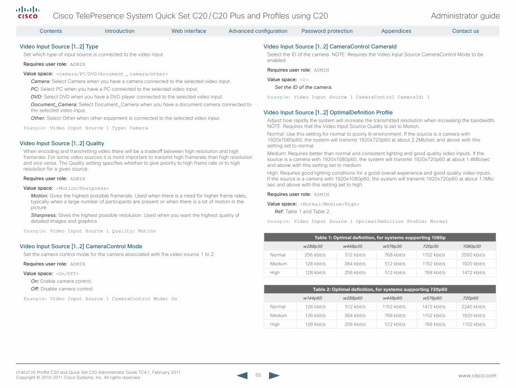
55
Cisco TelePresence System Quick Set C20 / C20 Plus and Profiles using C20 Administrator guide
D14637.05 Profile C20 and Quick Set C20 Administrator Guide TC4.1, February 2011. Copyright © 2010-2011 Cisco Systems, Inc. All rights reserved. www.cisco.com
Video Input Source [1..2] TypeSet which type of input source is connected to the video input.
requires user role: ADMIN
Value space: <camera/PC/DVD/document _ camera/other>
Camera: Select Camera when you have a camera connected to the selected video input.
PC: Select PC when you have a PC connected to the selected video input.
DVD: Select DVD when you have a DVD player connected to the selected video input.
Document_Camera: Select Document_Camera when you have a document camera connected to the selected video input.
Other: Select Other when other equipment is connected to the selected video input.
Example: Video Input Source 1 Type: Camera
Video Input Source [1..2] QualityWhen encoding and transmitting video there will be a tradeoff between high resolution and high framerate. For some video sources it is more important to transmit high framerate than high resolution and vice versa. The Quality setting specifies whether to give priority to high frame rate or to high resolution for a given source.
requires user role: ADMIN
Value space: <Motion/Sharpness>Motion: Gives the highest possible framerate. Used when there is a need for higher frame rates, typically when a large number of participants are present or when there is a lot of motion in the picture.
Sharpness: Gives the highest possible resolution. Used when you want the highest quality of detailed images and graphics.
Example: Video Input Source 1 Quality: Motion
Video Input Source [1..2] CameraControl ModeSet the camera control mode for the camera associated with the video source 1 to 2.
requires user role: ADMIN
Value space: <On/Off>On: Enable camera control.
Off: Disable camera control.
Example: Video Input Source 1 CameraControl Mode: On
Video Input Source [1..2] CameraControl CameraIdSelect the ID of the camera. NOTE: Requires the Video Input Source CameraControl Mode to be enabled.
requires user role: ADMIN
Value space: <1>Set the ID of the camera.
Example: Video Input Source 1 CameraControl CameraId: 1
Video Input Source [1..2] OptimalDefinition ProfileAdjust how rapidly the system will increase the transmitted resolution when increasing the bandwidth. NOTE: Requires that the Video Input Source Quality is set to Motion.
Normal: Use this setting for normal to poorly lit environment. If the source is a camera with 1920x1080p60, the system will transmit 1920x720p60 at about 2.2Mb/sec and above with this setting set to normal.
Medium: Requires better than normal and consistent lighting and good quality video inputs. If the source is a camera with 1920x1080p60, the system will transmit 1920x720p60 at about 1.4Mb/sec and above with this setting set to medium.
High: Requires good lighting conditions for a good overall experience and good quality video inputs. If the source is a camera with 1920x1080p60, the system will transmit 1920x720p60 at about 1.1Mb/sec and above with this setting set to high.
requires user role: ADMIN
Value space: <Normal/Medium/High>Ref: Table 1 and Table 2.
Example: Video Input Source 1 OptimalDefinition Profile: Normal
.
Table1:Optimaldefinition,forsystemssupporting1080p
w288p30 w448p30 w576p30 720p30 1080p30
Normal 256 kbit/s 512 kbit/s 768 kbit/s 1152 kbit/s 2560 kbit/s
Medium 128 kbit/s 384 kbit/s 512 kbit/s 1152 kbit/s 1920 kbit/s
High 128 kbit/s 256 kbit/s 512 kbit/s 768 kbit/s 1472 kbit/s
Table2:Optimaldefinition,forsystemssupporting720p60
w144p60 w288p60 w448p60 w576p60 720p60
Normal 128 kbit/s 512 kbit/s 1152 kbit/s 1472 kbit/s 2240 kbit/s
Medium 128 kbit/s 384 kbit/s 768 kbit/s 1152 kbit/s 1920 kbit/s
High 128 kbit/s 256 kbit/s 512 kbit/s 768 kbit/s 1152 kbit/s
56
Cisco TelePresence System Quick Set C20 / C20 Plus and Profiles using C20 Administrator guide
D14637.05 Profile C20 and Quick Set C20 Administrator Guide TC4.1, February 2011. Copyright © 2010-2011 Cisco Systems, Inc. All rights reserved. www.cisco.com
Video Input Source [1..2] OptimalDefinition Threshold60fpsFor each video input, this setting tells the system the lowest resolution where it should transmit 60fps. So for all resolutions lower than this, the maximum transmitted framerate would be 30fps, while above this resolution 60fps would also be possible, if the available bandwidth is adequate.
requires user role: ADMIN
Value space: <512 _ 288/768 _ 448/1024 _ 576/1280 _ 720/Never>
512_288: Set the threshold to 512x288.
768_448: Set the threshold to 768x448.
1024_576: Set the threshold to 1024x576.
1280_720: Set the threshold to 1280x720.
Never: Do not set a threshold for transmitting 60fps.
Example: Video Input Source 1 OptimalDefinition Threshold60fps: 1280 _ 720
Video Input DVI [2] TypeThe official DVI standard supports both digital and analog signals. In most cases the default AutoDetect setting can detect whether the signal is analog RGB or digital. However, in some rare cases when DVI-I cables are used (these cables can carry both the analog and digital signals) the auto detection fails. This setting makes it possible to override the AutoDetect and select the correct DVI video input.
requires user role: USER
Value space: <AutoDetect/Digital/AnalogRGB>AutoDetect: Set to AutoDetect to automatically detect if the signal is analog RGB or digital.
Digital: Set to Digital to force the DVI video input to Digital when using DVI-I cables with both analog and digital pins and AutoDetect fails.
AnalogRGB: Set to AnalogRGB to force the DVI video input to AnalogRGB when using DVI-I cables with both analog and digital pins and AutoDetect fails.
Example: Video Input DVI 2 Type: AutoDetect
Video Output HDMI [1..2] resolutionSelect the preferred resolution for the monitor connected to the video output HDMI connector. This will force the resolution on the monitor.
requires user role: ADMIN
Value space: <Auto/640 _ 480 _ 60/800 _ 600 _ 60/1024 _ 768 _ 60/1280 _ 1024 _ 60/1280 _ 720 _ 60/1920 _ 1080 _ 60/1280 _ 768 _ 60/1360 _ 768 _ 60/1366 _ 768 _ 60/1600 _ 1200 _ 60/1920 _ 1200 _ 60>
Auto: The system will automatically try to set the optimal resolution based on negotiation with the connected monitor.
Range: 640x480@60p, 800x600@60p, 1024x768@60p, 1280x1024@60p, 1280x720@60p, 1920x1080@60p, 1280x768@60p, 1360x768@60p, 1366x768@60p, 1600x1200@60p, 1920x1200@60p
Example: Video Output HDMI 1 Resolution: 1920 _ 1080 _ 60
Video Output HDMI [1..2] OverscanLevelSome TVs or other monitors may not display the whole image sent out on the systems video output, but cuts the outer parts of the image. In this case this setting can be used to let the system not use the outer parts of video resolution. Both the video and the OSD menu will be scaled in this case.
requires user role: ADMIN
Value space: <Medium/High/None>Medium: The system will not use the outer 3% of the output resolution.
High: The system will not use the outer 6% of the output resolution
None: The system will use all of the output resolution.
Example: Video Output HDMI 1 OverscanLevel: None
Video Output HDMI [1..2] MonitorroleThe HDMI monitor role describes what video stream will be shown on the monitor connected to the video output HDMI connector. Applicable only if the "Video > Monitors" configuration is set to dual.
requires user role: ADMIN
Value space: <First/Second/PresentationOnly>First: Show main video stream.
Second: Show presentation video stream if active, or other participants.
PresentationOnly: Show presentation video stream if active, and nothing else.
Example: Video Output HDMI 1 MonitorRole: First
Video Layout ScalingDefine how the system shall adjust the aspect ratio for images or frames when there is a difference between the image and the frame it is to be placed in.
requires user role: ADMIN
Value space: <On/Off>On: Let the system automatically adjust aspect ratio.
Off: No adjustment of the aspect ratio.
Example: Video Layout Scaling: On
57
Cisco TelePresence System Quick Set C20 / C20 Plus and Profiles using C20 Administrator guide
D14637.05 Profile C20 and Quick Set C20 Administrator Guide TC4.1, February 2011. Copyright © 2010-2011 Cisco Systems, Inc. All rights reserved. www.cisco.com
Video Layout ScaleToFrameDefine what to do if the aspect ratio of a video input source doesn't match the aspect ratio of the corresponding image frame in a composition. For example if you have a 4:3 input source (like XGA) to be displayed on a 16:9 output (like HD720).
requires user role: ADMIN
Value space: <Manual/MaintainAspectRatio/StretchToFit>Manual: If the difference in aspect ratio between the video input source and the target image frame is less than the ScaleToFrameThreshold configuration (in percent), the image is stretched to fit. If not, the system will maintain the original aspect ratio.
MaintainAspectRatio: Will maintain the aspect ratio of the input source, and fill in black in the rest of the frame (letter boxing or pillar boxing).
StretchToFit: Will stretch (horizontally or vertically) the input source to fit into the image frame. NOTE: The general limitation is that you cannot upscale in one direction and at the same time downscale in the other direction. In such situations the codec will apply letterboxing.
Example: Video Layout ScaleToFrame: MaintainAspectRatio
Video Layout ScaleToFrameThresholdOnly applicable if the ScaleToFrame configuration is set to manual. If the difference in aspect ratio between the video input source and the target image frame is less than the ScaleToFrameThreshold configuration (in percent), the image is stretched to fit. If not, the system will maintain the original aspect ratio.
requires user role: ADMIN
Value space: <0..100>Range: Select a value from 0 to 100 percent.
Example: Video Layout ScaleToFrameThreshold: 5
Video Layout LocalLayoutFamilySelect which video layout family to be used locally.
requires user role: ADMIN
Value space: <Auto/FullScreen/Equal/PresentationSmallSpeaker/PresentationLargeSpeaker>
Auto: The default layout family, as given by the layout database, will be used as the local layout. For more information about the layout database, see the command: xCommand Video Layout LoadDb.
FullScreen: The FullScreen layout family will be used as the local layout.
Equal: The Equal layout family will be used as the local layout.
PresentationSmallSpeaker: The PresentationSmallSpeaker layout family will be used as the local layout.
PresentationLargeSpeaker: The PresentationLargeSpeaker layout family will be used as the local layout.
Example: Video Layout LocalLayoutFamily: Auto
Video Layout remoteLayoutFamilySelect which video layout family to be used for the remote participants.
requires user role: ADMIN
Value space: <Auto/FullScreen/Equal/PresentationSmallSpeaker/PresentationLargeSpeaker>
Auto: The default layout family, as given by the local layout database, will be used as the remote layout. For more information about the layout database, see the command: xCommand Video Layout LoadDb.
FullScreen: The FullScreen layout family will be used as the remote layout.
Equal: The Equal layout family will be used as the remote layout.
PresentationSmallSpeaker: The PresentationSmallSpeaker layout family will be used as the remote layout.
PresentationLargeSpeaker: The PresentationLargeSpeaker layout family will be used as the remote layout.
Example: Video Layout RemoteLayoutFamily: Auto
Video OSD ModeThe Video OSD (On Screen Display) Mode lets you define if information and icons should be displayed on screen.
requires user role: ADMIN
Value space: <On/Off>On: Show the on screen menus, icons and indicators.
Off: Hide the on screen menus, icons and indicators.
Example: Video OSD Mode: On
Video OSD TodaysBookingsThis setting can be used to display the systems bookings for today on the main OSD menu. This requires that the system is bookable by an external booking system, like Cisco TelePresence Management Suite (TMS).
requires user role: ADMIN
Value space: <On/Off>On: Displays information about this systems bookings on screen.
Off: Do not display todays bookings.
Example: Video OSD TodaysBookings: Off
58
Cisco TelePresence System Quick Set C20 / C20 Plus and Profiles using C20 Administrator guide
D14637.05 Profile C20 and Quick Set C20 Administrator Guide TC4.1, February 2011. Copyright © 2010-2011 Cisco Systems, Inc. All rights reserved. www.cisco.com
Video OSD MyContactsExpandedSet how the local contacts will be displayed in the phone book dialog in the OSD (On Screen Display).
requires user role: ADMIN
Value space: <On/Off>On: The local contacts in the phone book will be shown in the top level of the phonebook dialog.
Off: The local contacts will be placed in a separate folder called MyContacts in the phonebook dialog.
Example: Video OSD MyContactsExpanded: Off
Video OSD OutputThe Video OSD (On Screen Display) Output lets you define which monitor should display the on screen menus, information and icons. By default the OSD is sent to the monitor connected to the Video OSD Output 1. If you cannot see the OSD on screen, then you must re-configure the OSD Output. You can do this by entering a key sequence on the remote control, from the web interface, or by a command line interface.
Using the remote control: Press the Disconnect key followed by: * # * # 0 x # (where x is output 1 to 2).
Using the web interface: Open a web browser and enter the IP address of the codec. Open the Advanced Configuration menu and navigate to Video OSD Output and select the video output.
Using a command line interface: Open a command line interface and connect to the codec (if in doubt of how to do this, see the API Guide for the codec). Enter the command: xConfiguration Video OSD Output [1..2] (select the OSD Output)
requires user role: ADMIN
Value space: <1..2>Range: Select 1 for HDMI output, or select 2 for DVI-I output.
Example: Video OSD Output: 1
Video OSD LoginrequiredDetermine if the system should require the user to login before accessing the On Screen Display (OSD). If enabled, the user must enter his username and his PIN. After the user has logged in he can only execute to the configurations changes and commands allowed by his Role.
requires user role: ADMIN
Value space: <On/Off>On: The user must log in to access the On Screen Display (OSD).
Off: No login to the OSD is required.
Example: Video OSD LoginRequired: Off
Video OSD InputMethod InputLanguageThe codec can be enabled for Cyrillic input characters in the menus on screen. NOTE: Requires that Video OSD inputMethod Cyrillic is set to On.
requires user role: ADMIN
Value space: <Latin/Cyrillic>Latin: Latin characters can be entered when using the remote control (default).
Cyrillic: Cyrillic characters can be entered using the remote control. NOTE: Requires a Cisco TelePresence Remote Control with Cyrillic fonts.
Example: Video OSD InputMethod InputLanguage: Latin
Video OSD InputMethod CyrillicSet the Cyrillic mode for the menu input language in the menus on screen.
requires user role: ADMIN
Value space: <On/Off>On: Cyrillic mode is available as a menu input language in the menus on screen. This will enable the setting Video OSD InputMethod InputLanguage.
Off: Cyrillic mode is NOT available as a menu input language in the menus on screen.
Example: Video OSD InputMethod Cyrillic: Off
59
Cisco TelePresence System Quick Set C20 / C20 Plus and Profiles using C20 Administrator guide
D14637.05 Profile C20 and Quick Set C20 Administrator Guide TC4.1, February 2011. Copyright © 2010-2011 Cisco Systems, Inc. All rights reserved. www.cisco.com
The Experimental settingsThe Experimental settings are beta preview features and can be used 'as is'. They are not fully documented.NOTE: The Experimental settings are likely to change without further notice.
Experimental CapsetFilterNOTE: This Experimental command can be used 'as is' and will not be further documented. The Experimental settings WILL change.
requires user role: ADMIN
Value space: <S: 0, 100>
Example: Experimental CapsetFilter: ""
Experimental NetworkServices UPnP ModeNOTE: This Experimental command can be used 'as is' and will not be further documented. The Experimental settings WILL change.
requires user role: ADMIN
Value space: <On/Off>
Example: Experimental NetworkServices UPnP Mode: Off
Experimental NetworkServices UPnP TimeoutNOTE: This Experimental command can be used 'as is' and will not be further documented. The Experimental settings WILL change.
requires user role: ADMIN
Value space: <0..3600>
Example: Experimental NetworkServices UPnP Timeout: 0
Experimental CustomSoftbuttons State [1..2] Softbutton [1..5] TypeNOTE: This Experimental command can be used 'as is' and will not be further documented. The Experimental settings WILL change.
requires user role: ADMIN
Value space: <NotSet/MainSource/PresentationSource/CameraPreset/Actions/SpeedDial>
Example: Experimental CustomSoftbuttons State 1 Softbutton 1 Type: NotSet
Experimental CustomSoftbuttons State [1..2] Softbutton [1..5] ValueNOTE: This Experimental command can be used 'as is' and will not be further documented. The Experimental settings WILL change.
requires user role: ADMIN
Value space: <S: 0, 255>
Example: Experimental CustomSoftbuttons State 1 Softbutton 1 Value: ""
Experimental Conference [1..1] PacketLossresilience ForwardErrorCorrectionNOTE: This Experimental command can be used 'as is' and will not be further documented. The Experimental settings WILL change.
Will enable ForwardErrorCorrection (RFC5109) mechanism as part of the PacketLossResilience mechanism. Default value is On.
On: Forward error correction will be used as part of the PacketLossResilience mechanism.
Off: Forward error correction will NOT be used as part of the PacketLossResilience mechanism.
requires user role: ADMIN
Value space: <On/Off>
Example: Experimental Conference 1 PacketLossResilience ForwardErrorCorrection: On
Experimental Conference [1..1] PacketLossresilience rateAdaptionNOTE: This Experimental command can be used 'as is' and will not be further documented. The Experimental settings WILL change.
Will use the a RateAdaption algorithm adapted to the PacketLossResilience mechanism. Default value is On.
On: RateAdaption will be used as part of the PacketLossResilience mechanism.
Off: RateAdaption will NOT be used as part of the PacketLossResilience mechanism.
requires user role: ADMIN
Value space: <On/Off>
Example: Experimental Conference 1 PacketLossResilience RateAdaption: On
Experimental SoftwareUpgrade ModeNOTE: This Experimental command can be used 'as is' and will not be further documented. The Experimental settings WILL change.
requires user role: ADMIN
Value space: <Auto/Manual>
Example: Experimental SoftwareUpgrade Mode: Auto
60
Cisco TelePresence System Quick Set C20 / C20 Plus and Profiles using C20 Administrator guide
D14637.05 Profile C20 and Quick Set C20 Administrator Guide TC4.1, February 2011. Copyright © 2010-2011 Cisco Systems, Inc. All rights reserved. www.cisco.com
Experimental SoftwareUpgrade ServerAddressNOTE: This Experimental command can be used 'as is' and will not be further documented. The Experimental settings WILL change.
requires user role: ADMIN
Value space: <S: 0, 255>
Example: Experimental SoftwareUpgrade ServerAddress: "http://csupdate.tandberg.com/getswlist.py"
Experimental SystemUnit MenuTypeNOTE: This Experimental command can be used 'as is' and will not be further documented. The Experimental settings WILL change.
requires user role: ADMIN
Value space: <Indicators/Full>
Example: Experimental SystemUnit MenuType: Full

61
Cisco TelePresence System Quick Set C20 / C20 Plus and Profiles using C20 Administrator guide
D14637.05 Profile C20 and Quick Set C20 Administrator Guide TC4.1, February 2011. Copyright © 2010-2011 Cisco Systems, Inc. All rights reserved. www.cisco.com
Chapter 4
Password protection
62
Cisco TelePresence System Quick Set C20 / C20 Plus and Profiles using C20 Administrator guide
D14637.05 Profile C20 and Quick Set C20 Administrator Guide TC4.1, February 2011. Copyright © 2010-2011 Cisco Systems, Inc. All rights reserved. www.cisco.com
Set the Administrator settings menu passwordWhen you set a password for the Administrator settings menu, all users must enter the password to get access to this menu, either on screen when using a remote control, or on the touch screen if you are using a Touch controller.The menu password can be set from the on-screen menu, using a remote control or from a command line interface.
Set the menu password using the remote control
Perform the following steps to define a password for the Administrator settings menu:
1. In the on screen menu, go to Home > Settings > Administrator settings > Set menu password.The password format is a string with 0–255 characters.
2. Enter the new password in the Set password menu.3. Press Save.
Perform the following steps to change the password for the Administrator settings menu:
1. To change the password, go to Home > Settings > Administrator settings > Set menu password.
2. Enter the new password in the Set password menu.3. Press Save.
Perform the following steps to deactivate the password for the Administrator settings menu:
1. To deactivate the password, go to Home > Settings > Administrator settings > Set menu password.
2. Leave the input field empty in the Set password menu.3. Press Save to save the blank password. This will deactivate
the Administrator settings menu password.
Set the menu password from a command line interface
Open a command line interface, for example PuTTY, and run the following command:xCommand SystemUnit MenuPassword Set Password: <password>
Password protectionThe system is password protected in the following ways:
• The Administrator settings menu can be password protected with a menu password.
• The Codec is password protected. You always need to enter a username to log in. The same username and password is used for the web and command line interfaces.You can also configure the codec to prompt for a PIN-code before accessing all the on screen menus.» The default username is admin with no password set.
NOTE: We recommend that you set a password for the admin user - see how to Change your codec password to the right.» New user accounts with username and password/PIN-
code can be created using the web interface. Read more about user rights and how to add, edit and delete a user account in the User management section.
• You can protect the File system of the codec by setting a password for the root user. The root user is disabled by default.
NOTE: When a new administrator password has been defined make sure you keep a copy of the password in a safe place. Contact your Cisco representative if you have forgotten the password.
Change your codec passwordA user, including the default admin user, can change his codec password using the web interface or the command line interface.If a password is not currently set, use the procedure below with a blank current password.
Change the password using the web interface
Perform the following steps to change the codec password:
1. Log in to the web interface with your username and current password.
2. Go to the Change password page.3. Enter the current password, the new password, and repeat
the new password in the appropriate input fields. The password format is a string with 0–255 characters.
4. Click Save.
Change the password using the command line interface
Perform the following steps to change the codec password:
1. Connect to the codec through the network or the serial data port, using a command line interface (SSH or Telnet).
2. Log in to the codec with your username and current password.
3. Run the following API command and when prompted enter the current password, the new password, and confirm the new password: systemtools passwd
The password format is a string with 0–255 characters.
63
Cisco TelePresence System Quick Set C20 / C20 Plus and Profiles using C20 Administrator guide
D14637.05 Profile C20 and Quick Set C20 Administrator Guide TC4.1, February 2011. Copyright © 2010-2011 Cisco Systems, Inc. All rights reserved. www.cisco.com
Set a root passwordIf you log in to the command line interface as root, you can access the codec’s file system.
The root user is disabled by default.
Perform the following steps to activate the root user and set a password:
1. Connect to the codec through the network or the serial data port, using a command line interface (SSH or Telnet).
2. Log in to the codec with the username (admin) and password. You need ADMIN rights.
3. Run the following API command:systemtools rootsettings on <password>
NOTE: The root password is not the same as the administrator password.
Change the user passwordsAll users can change their own codec password as described on the previous page.If you have ADMIN rights, you can change all users’ passwords by performing the following steps:
1. Log in to the web interface with username and password.2. Go to the Users page.3. Select the appropriate user from the list.4. Enter a new password and PIN code. 5. Click Save.

64
Cisco TelePresence System Quick Set C20 / C20 Plus and Profiles using C20 Administrator guide
D14637.05 Profile C20 and Quick Set C20 Administrator Guide TC4.1, February 2011. Copyright © 2010-2011 Cisco Systems, Inc. All rights reserved. www.cisco.com
Chapter 5
Appendices
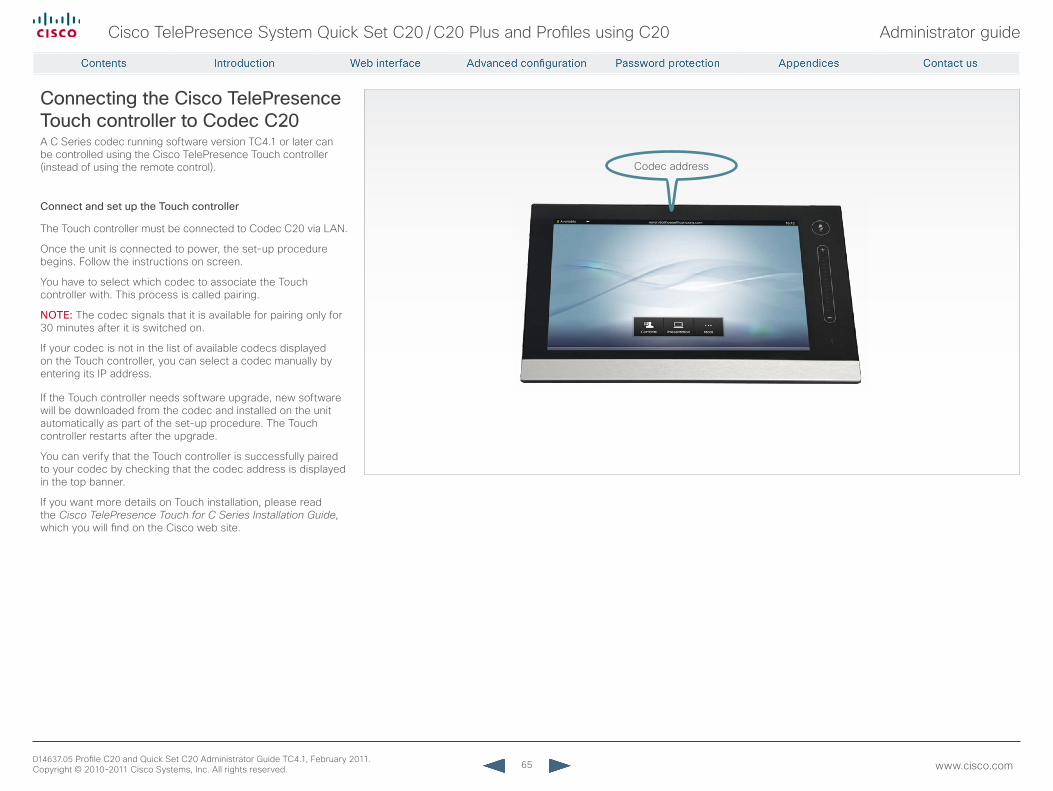
65
Cisco TelePresence System Quick Set C20 / C20 Plus and Profiles using C20 Administrator guide
D14637.05 Profile C20 and Quick Set C20 Administrator Guide TC4.1, February 2011. Copyright © 2010-2011 Cisco Systems, Inc. All rights reserved. www.cisco.com
Connecting the Cisco TelePresence Touch controller to Codec C20A C Series codec running software version TC4.1 or later can be controlled using the Cisco TelePresence Touch controller (instead of using the remote control).
Connect and set up the Touch controller
The Touch controller must be connected to Codec C20 via LAN.
Once the unit is connected to power, the set-up procedure begins. Follow the instructions on screen.
You have to select which codec to associate the Touch controller with. This process is called pairing.
NOTE: The codec signals that it is available for pairing only for 30 minutes after it is switched on.
If your codec is not in the list of available codecs displayed on the Touch controller, you can select a codec manually by entering its IP address.
If the Touch controller needs software upgrade, new software will be downloaded from the codec and installed on the unit automatically as part of the set-up procedure. The Touch controller restarts after the upgrade.
You can verify that the Touch controller is successfully paired to your codec by checking that the codec address is displayed in the top banner.
If you want more details on Touch installation, please read the Cisco TelePresence Touch for C Series Installation Guide, which you will find on the Cisco web site.
Codec address
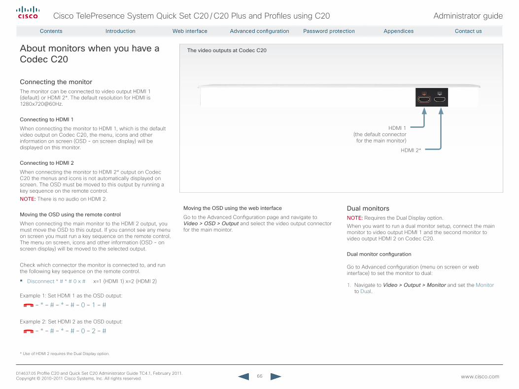
66
Cisco TelePresence System Quick Set C20 / C20 Plus and Profiles using C20 Administrator guide
D14637.05 Profile C20 and Quick Set C20 Administrator Guide TC4.1, February 2011. Copyright © 2010-2011 Cisco Systems, Inc. All rights reserved. www.cisco.com
The video outputs at Codec C20About monitors when you have a Codec C20
Connecting the monitorThe monitor can be connected to video output HDMI 1 (default) or HDMI 2*. The default resolution for HDMI is 1280x720@60Hz.
Connecting to HDMI 1
When connecting the monitor to HDMI 1, which is the default video output on Codec C20, the menu, icons and other information on screen (OSD - on screen display) will be displayed on this monitor.
Connecting to HDMI 2
When connecting the monitor to HDMI 2* output on Codec C20 the menus and icons is not automatically displayed on screen. The OSD must be moved to this output by running a key sequence on the remote control.NOTE: There is no audio on HDMI 2.
Moving the OSD using the remote control
When connecting the main monitor to the HDMI 2 output, you must move the OSD to this output. If you cannot see any menu on screen you must run a key sequence on the remote control. The menu on screen, icons and other information (OSD - on screen display) will be moved to the selected output.
Check which connector the monitor is connected to, and run the following key sequence on the remote control.
• Disconnect * # * # 0 x # x=1 (HDMI 1) x=2 (HDMI 2) Example 1: Set HDMI 1 as the OSD output:
– * – # – * – # – 0 – 1 – #
Example 2: Set HDMI 2 as the OSD output:
– * – # – * – # – 0 – 2 – #
Dual monitorsNOTE: Requires the Dual Display option.When you want to run a dual monitor setup, connect the main monitor to video output HDMI 1 and the second monitor to video output HDMI 2 on Codec C20.
Dual monitor configuration
Go to Advanced configuration (menu on screen or web interface) to set the monitor to dual:
1. Navigate to Video > Output > Monitor and set the Monitor to Dual.
HDMI 1 (the default connector for the main monitor)
HDMI 2*
* Use of HDMI 2 requires the Dual Display option.
Moving the OSD using the web interface
Go to the Advanced Configuration page and navigate to Video > OSD > Output and select the video output connector for the main mointor.
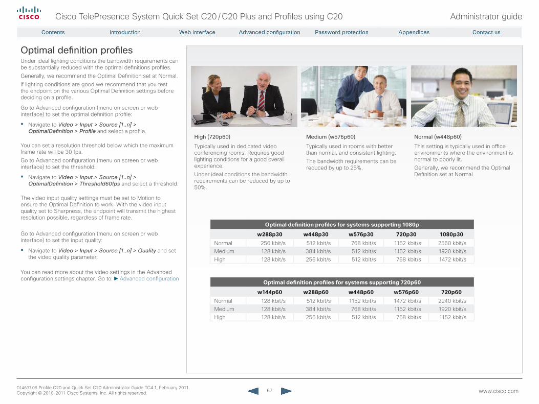
67
Cisco TelePresence System Quick Set C20 / C20 Plus and Profiles using C20 Administrator guide
D14637.05 Profile C20 and Quick Set C20 Administrator Guide TC4.1, February 2011. Copyright © 2010-2011 Cisco Systems, Inc. All rights reserved. www.cisco.com
Optimal definition profilesUnder ideal lighting conditions the bandwidth requirements can be substantially reduced with the optimal definitions profiles.Generally, we recommend the Optimal Definition set at Normal. If lighting conditions are good we recommend that you test the endpoint on the various Optimal Definition settings before deciding on a profile.
Go to Advanced configuration (menu on screen or web interface) to set the optimal definition profile:
• Navigate to Video > Input > Source [1..n] > OptimalDefinition > Profile and select a profile.
You can set a resolution threshold below which the maximum frame rate will be 30 fps.Go to Advanced configuration (menu on screen or web interface) to set the threshold:
• Navigate to Video > Input > Source [1..n] > OptimalDefinition > Threshold60fps and select a threshold.
The video input quality settings must be set to Motion to ensure the Optimal Definition to work. With the video input quality set to Sharpness, the endpoint will transmit the highest resolution possible, regardless of frame rate.
Go to Advanced configuration (menu on screen or web interface) to set the input quality:
• Navigate to Video > Input > Source [1..n] > Quality and set the video quality parameter.
You can read more about the video settings in the Advanced configuration settings chapter. Go to: Advanced configuration
High (720p60)
Typically used in dedicated video conferencing rooms. Requires good lighting conditions for a good overall experience. Under ideal conditions the bandwidth requirements can be reduced by up to 50%.
Medium (w576p60)
Typically used in rooms with better than normal, and consistent lighting.The bandwidth requirements can be reduced by up to 25%.
Normal (w448p60)
This setting is typically used in office environments where the environment is normal to poorly lit. Generally, we recommend the Optimal Definition set at Normal.
Optimaldefinitionprofilesforsystemssupporting1080p
w288p30 w448p30 w576p30 720p30 1080p30Normal 256 kbit/s 512 kbit/s 768 kbit/s 1152 kbit/s 2560 kbit/sMedium 128 kbit/s 384 kbit/s 512 kbit/s 1152 kbit/s 1920 kbit/sHigh 128 kbit/s 256 kbit/s 512 kbit/s 768 kbit/s 1472 kbit/s
Optimaldefinitionprofilesforsystemssupporting720p60
w144p60 w288p60 w448p60 w576p60 720p60Normal 128 kbit/s 512 kbit/s 1152 kbit/s 1472 kbit/s 2240 kbit/sMedium 128 kbit/s 384 kbit/s 768 kbit/s 1152 kbit/s 1920 kbit/sHigh 128 kbit/s 256 kbit/s 512 kbit/s 768 kbit/s 1152 kbit/s
68
Cisco TelePresence System Quick Set C20 / C20 Plus and Profiles using C20 Administrator guide
D14637.05 Profile C20 and Quick Set C20 Administrator Guide TC4.1, February 2011. Copyright © 2010-2011 Cisco Systems, Inc. All rights reserved. www.cisco.com
ClearPath — Packet loss resilienceClearPath introduces advanced packet loss resilience mechanisms that increase the experienced quality when you use your video system in an error prone environment.
We recommend that you enable ClearPath on your video system.
Go to Advanced configuration (menu on screen or web interface) to switch on ClearPath:• Navigate to Conference 1 > PacketLossResilience > Mode
and select On.
69
Cisco TelePresence System Quick Set C20 / C20 Plus and Profiles using C20 Administrator guide
D14637.05 Profile C20 and Quick Set C20 Administrator Guide TC4.1, February 2011. Copyright © 2010-2011 Cisco Systems, Inc. All rights reserved. www.cisco.com
requirement for speaker systems connected to a Cisco TelePresence C Series codecCisco has put in a lot of effort to minimize the camera to screen delay on our TelePresence endpoints.
New consumer TVs are usually equipped with “Motion Flow” or similar technology to insert new video frames between standard frames to create smoother images. This processing takes time and to maintain lip synchronization, the TV will delay the audio so that the audio and video arrives at the same time.
The echo canceller in the Cisco endpoints can handle such delay up to 30 ms. Many consumer TVs are not made for real time video communication and may introduce more than 30 ms of delay.
If you use such a TV together with a C Series codec it is recommended that you turn off “Motion Flow”, “Natural Motion” or any other video processing that introduces additional delay.
Some consumer TVs also support advanced audio processing like “Virtual Surround” effects and “Dynamic Compression” to improve the TV experience. Such processing will make any acoustic echo canceller malfunction and should hence be switched off.
Some monitors are equipped with a setting called ‘Game Mode’. This mode is specifically designed to help reduce the response time and will usually help to reduce the delay.
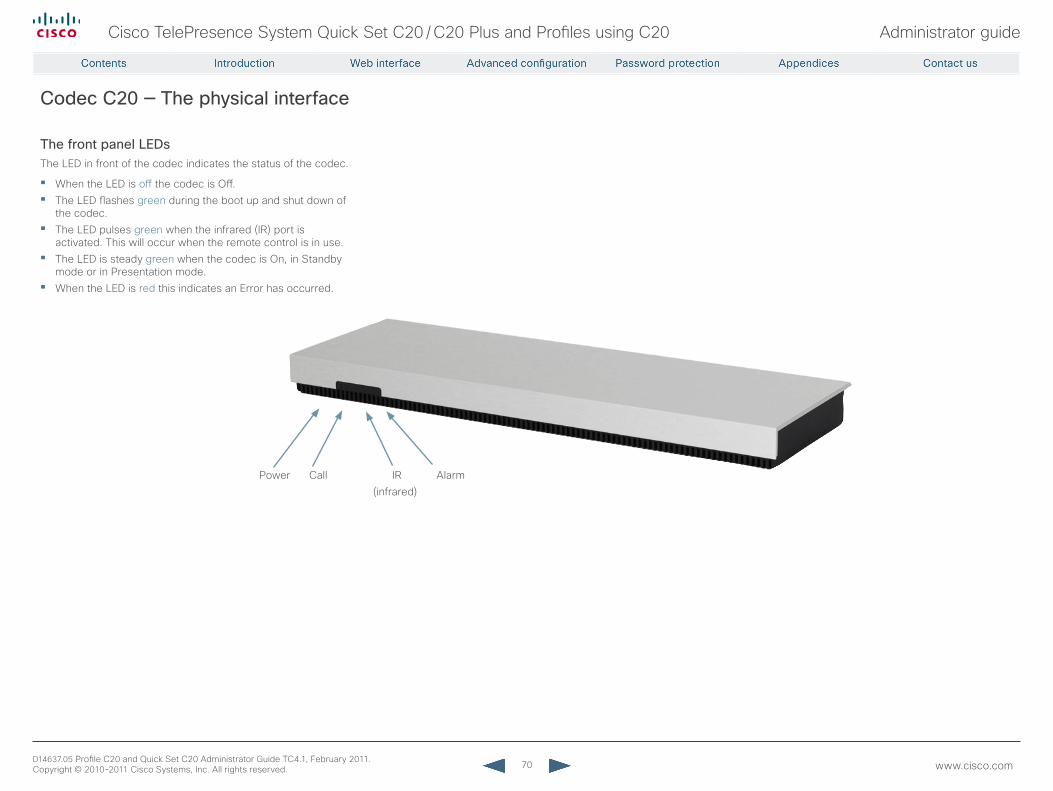
70
Cisco TelePresence System Quick Set C20 / C20 Plus and Profiles using C20 Administrator guide
D14637.05 Profile C20 and Quick Set C20 Administrator Guide TC4.1, February 2011. Copyright © 2010-2011 Cisco Systems, Inc. All rights reserved. www.cisco.com
Codec C20 — The physical interface
The front panel LEDsThe LED in front of the codec indicates the status of the codec.
• When the LED is off the codec is Off.• The LED flashes green during the boot up and shut down of
the codec.• The LED pulses green when the infrared (IR) port is
activated. This will occur when the remote control is in use.• The LED is steady green when the codec is On, in Standby
mode or in Presentation mode.• When the LED is red this indicates an Error has occurred.
Power Call IR Alarm (infrared)
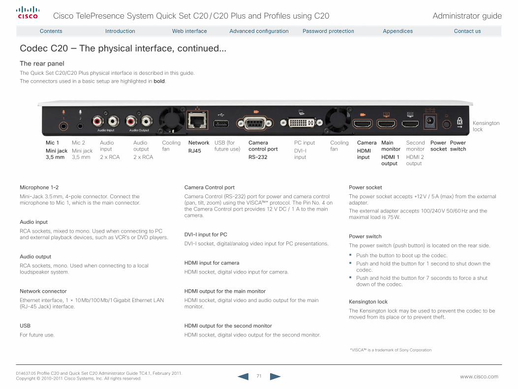
71
Cisco TelePresence System Quick Set C20 / C20 Plus and Profiles using C20 Administrator guide
D14637.05 Profile C20 and Quick Set C20 Administrator Guide TC4.1, February 2011. Copyright © 2010-2011 Cisco Systems, Inc. All rights reserved. www.cisco.com
Mic 1Mini jack 3,5 mm
Audio input2 x RCA
Audio output2 x RCA
Cooling fan
NetworkrJ45
USB (for future use)
Camera control portrS-232
PC inputDVI-I input
Cooling fan
CameraHDMI input
Main monitorHDMI 1 output
Second monitorHDMI 2 output
Power socket
Power switch
Kensington lock
Microphone 1–2
Mini-Jack 3.5 mm, 4-pole connector. Connect the microphone to Mic 1, which is the main connector.
Audio input
RCA sockets, mixed to mono. Used when connecting to PC and external playback devices, such as VCR’s or DVD players.
Audio output
RCA sockets, mono. Used when connecting to a local loudspeaker system.
Network connector
Ethernet interface, 1 × 10 Mb/100 Mb/1 Gigabit Ethernet LAN (RJ-45 Jack) interface.
USB
For future use.
Camera Control port
Camera Control (RS-232) port for power and camera control (pan, tilt, zoom) using the VISCA™* protocol. The Pin No. 4 on the Camera Control port provides 12 V DC / 1 A to the main camera.
DVI-I input for PC
DVI-I socket, digital/analog video input for PC presentations.
HDMI input for camera
HDMI socket, digital video input for camera.
HDMI output for the main monitor
HDMI socket, digital video and audio output for the main monitor.
HDMI output for the second monitor
HDMI socket, digital video output for the second monitor.
Power socket
The power socket accepts +12 V / 5 A (max) from the external adapter.The external adapter accepts 100/240 V 50/60 Hz and the maximal load is 75 W.
Power switch
The power switch (push button) is located on the rear side.
• Push the button to boot up the codec.• Push and hold the button for 1 second to shut down the
codec.• Push and hold the button for 7 seconds to force a shut
down of the codec.
Kensington lock
The Kensington lock may be used to prevent the codec to be moved from its place or to prevent theft.
*VISCA™ is a trademark of Sony Corporation
Codec C20 — The physical interface, continued...The rear panelThe Quick Set C20/C20 Plus physical interface is described in this guide. The connectors used in a basic setup are highlighted in bold.
Mic 2Mini jack 3,5 mm
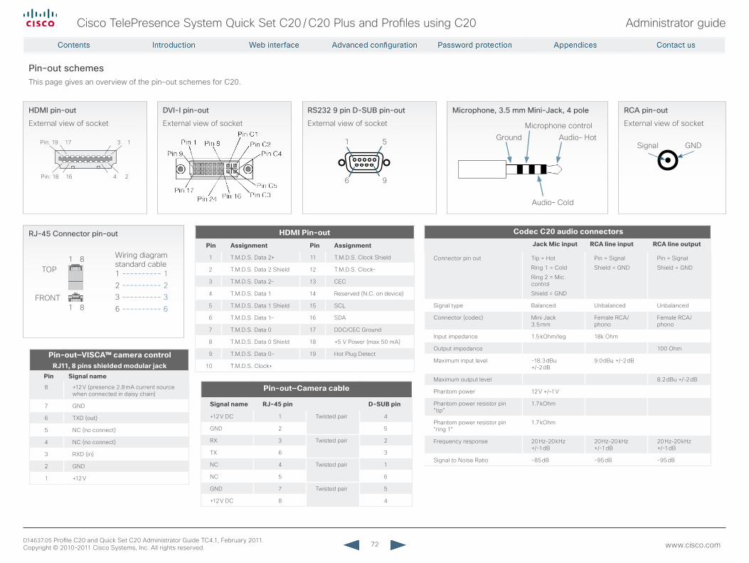
72
Cisco TelePresence System Quick Set C20 / C20 Plus and Profiles using C20 Administrator guide
D14637.05 Profile C20 and Quick Set C20 Administrator Guide TC4.1, February 2011. Copyright © 2010-2011 Cisco Systems, Inc. All rights reserved. www.cisco.com
Pin: 19 17 3 1
Pin: 18 16 4 2
HDMI pin-out
External view of socket
DVI-I pin-out
External view of socket
rCA pin-out
External view of socket
GNDSignal
rJ-45 Connector pin-out
1 ---------- 12 ---------- 23 ---------- 36 ---------- 6
Wiring diagram standard cable
TOP
FRONT
1 8
1 8
rS232 9 pin D-SUB pin-out
External view of socket
1 5
6 9
Pin-out schemesThis page gives an overview of the pin-out schemes for C20.
HDMIPin-outPin Assignment Pin Assignment
1 T.M.D.S. Data 2+ 11 T.M.D.S. Clock Shield
2 T.M.D.S. Data 2 Shield 12 T.M.D.S. Clock–
3 T.M.D.S. Data 2 – 13 CEC
4 T.M.D.S. Data 1 14 Reserved (N.C. on device)
5 T.M.D.S. Data 1 Shield 15 SCL
6 T.M.D.S. Data 1 – 16 SDA
7 T.M.D.S. Data 0 17 DDC/CEC Ground
8 T.M.D.S. Data 0 Shield 18 +5 V Power (max 50 mA)
9 T.M.D.S. Data 0– 19 Hot Plug Detect
10 T.M.D.S. Clock+
Pin-out—Cameracable
Signalname RJ-45pin D-SUBpin
+12 V DC 1 Twisted pair 4
GND 2 5
RX 3 Twisted pair 2
TX 6 3
NC 4 Twisted pair 1
NC 5 6
GND 7 Twisted pair 5
+12 V DC 8 4
Pin-out—VISCA™cameracontrolRJ11,8pinsshieldedmodularjack
Pin Signalname
8 +12 V (presence 2.8 mA current source when connected in daisy chain)
7 GND
6 TXD (out)
5 NC (no connect)
4 NC (no connect)
3 RXD (in)
2 GND
1 +12 V
CodecC20audioconnectorsJackMicinput RCAlineinput RCAlineoutput
Connector pin out Tip = Hot
Ring 1 = Cold
Ring 2 = Mic. control
Shield = GND
Pin = Signal
Shield = GND
Pin = Signal
Shield = GND
Signal type Balanced Unbalanced Unbalanced
Connector (codec) Mini Jack 3.5 mm
Female RCA/phono
Female RCA/phono
Input impedance 1.5 kOhm/leg 18k Ohm
Output impedance 100 Ohm
Maximum input level -18.3 dBu +/-2 dB
9.0 dBu +/-2 dB
Maximum output level 8.2 dBu +/-2 dB
Phantom power 12 V +/-1 V
Phantom power resistor pin ”tip”
1.7 kOhm
Phantom power resistor pin ”ring 1”
1.7 kOhm
Frequency response 20 Hz-20 kHz +/-1 dB
20 Hz-20 kHz +/-1 dB
20 Hz-20 kHz +/-1 dB
Signal to Noise Ratio -85 dB -95 dB -95 dB
Microphone, 3.5 mm Mini-Jack, 4 pole
Microphone controlGround Audio– Hot
Audio– Cold
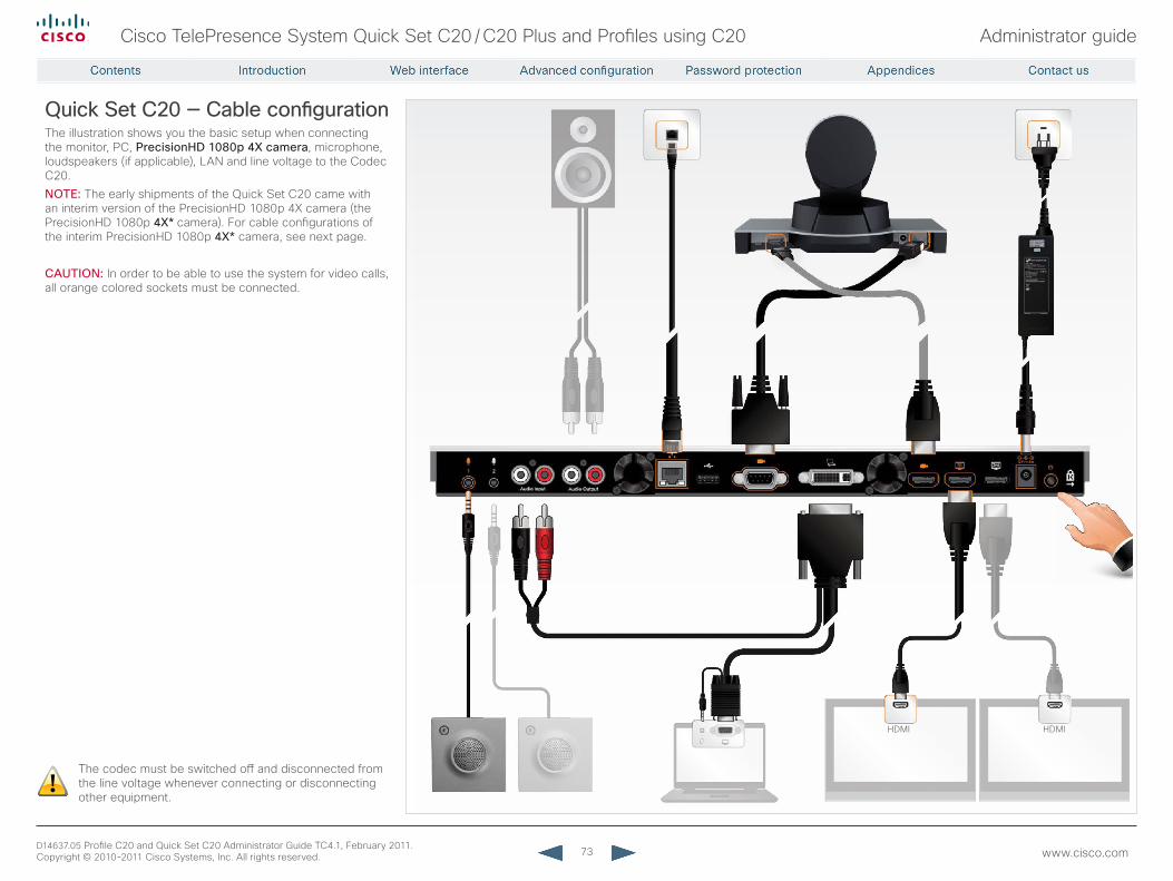
73
Cisco TelePresence System Quick Set C20 / C20 Plus and Profiles using C20 Administrator guide
D14637.05 Profile C20 and Quick Set C20 Administrator Guide TC4.1, February 2011. Copyright © 2010-2011 Cisco Systems, Inc. All rights reserved. www.cisco.com
!
Quick Set C20 — Cable configurationThe illustration shows you the basic setup when connecting the monitor, PC, PrecisionHD 1080p 4X camera, microphone, loudspeakers (if applicable), LAN and line voltage to the Codec C20.NOTE: The early shipments of the Quick Set C20 came with an interim version of the PrecisionHD 1080p 4X camera (the PrecisionHD 1080p 4X*camera). For cable configurations of the interim PrecisionHD 1080p 4X* camera, see next page.
CAUTION: In order to be able to use the system for video calls, all orange colored sockets must be connected.
The codec must be switched off and disconnected from the line voltage whenever connecting or disconnecting other equipment.
HDMI HDMI
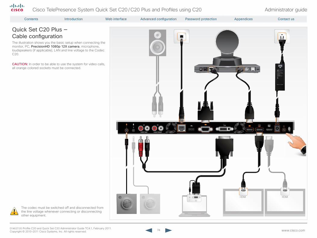
74
Cisco TelePresence System Quick Set C20 / C20 Plus and Profiles using C20 Administrator guide
D14637.05 Profile C20 and Quick Set C20 Administrator Guide TC4.1, February 2011. Copyright © 2010-2011 Cisco Systems, Inc. All rights reserved. www.cisco.com
!
Quick Set C20 Plus — Cable configurationThe illustration shows you the basic setup when connecting the monitor, PC, PrecisionHD 1080p 12X camera, microphone, loudspeakers (if applicable), LAN and line voltage to the Codec C20.
CAUTION: In order to be able to use the system for video calls, all orange colored sockets must be connected.
The codec must be switched off and disconnected from the line voltage whenever connecting or disconnecting other equipment.
HDMI HDMI
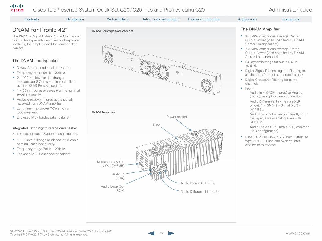
75
Cisco TelePresence System Quick Set C20 / C20 Plus and Profiles using C20 Administrator guide
D14637.05 Profile C20 and Quick Set C20 Administrator Guide TC4.1, February 2011. Copyright © 2010-2011 Cisco Systems, Inc. All rights reserved. www.cisco.com
The DNAM Amplifier
• 3 × 50 W continuous average Center Output Power (load specified by DNAM Center Loudspeakers).
• 2 × 50 W continuous average Stereo Output Power (load specified by DNAM Stereo Loudspeakers).
• Full dynamic range for audio (20 Hz–20 kHz).
• Digital Signal Processing and Filtering on all channels for best audio detail clarity.
• Digital Crossover Filtering on center channels.
• In/out:Audio In - SPDIF (stereo) or Analog (mono), using the same connector.Audio Differential In - (female XLR pinout: 1 - GND, 2 – Signal (+), 3 – Signal (-)).Audio Loop Out - line out directly from the input, always analog even with SPDIF in.Audio Stereo Out - (male XLR, common GND configuration).
• Fuse 2 A 250 V Slow, 5 × 20 mm, Littelfuse type 215002. Push and twist counter-clockwise to release.
DNAM for Profile 42”The DNAM – Digital Natural Audio Module – is built on two specially designed and separate modules, the amplifier and the loudspeaker cabinet.
The DNAM Loudspeaker
• 3-way Center Loudspeaker system.• Frequency range 50 Hz - 20 kHz.• 2 × 100 mm low- and midrange
loudspeaker 8 Ohms nominal, excellent quality (SEAS Prestige series).
• 1 × 25 mm dome tweeter, 6 ohms nominal, excellent quality.
• Active crossover filtered audio signals received from DNAM amplifier.
• Long time max power 70 Watt on all loudspeakers.
• Enclosed MDF loudspeaker cabinet.
Integrated Left / right Stereo Loudspeaker
Stereo Loudspeaker System, each side has:
• 1 × 90 mm fullrange loudspeaker, 8 ohms nominal, excellent quality.
• Frequency range 70 Hz - 20 kHz.• Enclosed MDF Loudspeaker cabinet.
Power socketDNAM Amplifier
DNAM Loudspeaker cabinet
Fuse
Audio Stereo Out (XLR)
Audio Differential In (XLR)
Multiaccess Audio In / Out (D-SUB)
Audio In (RCA)
Audio Loop Out (RCA)
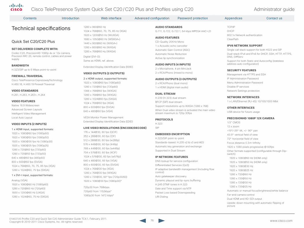
76
Cisco TelePresence System Quick Set C20 / C20 Plus and Profiles using C20 Administrator guide
D14637.05 Profile C20 and Quick Set C20 Administrator Guide TC4.1, February 2011. Copyright © 2010-2011 Cisco Systems, Inc. All rights reserved. www.cisco.com
Technical specifications
Quick Set C20/C20 Plus
SETDELIVEREDCOMPLETEWITH:Codec C20, PrecisionHD 1080p 4x or 12x camera, Precision MIC 20, remote control, cables and power supply
BANDWIDTHH.323/SIP up to 6 Mbps point-to-point
FIREWALLTRAVERSALCisco TelePresence ExpresswayTechnology
H.460.18, H.460.19 Firewall Traversal
VIDEOSTANDARDSH.261, H.263, H.263+, H.264
VIDEOFEATURESNative 16:9 Widescreen
Advanced Screen Layouts
Intelligent Video Management
Local Auto Layout
VIDEOINPUTS(2INPUTS)
1 x HDMI input, supported formats:
1920 x 1080@60 fps (1080p60)
1920 x 1080@50 fps (1080p50)
1920 x 1080@30 fps Hz (1080p30)
1920 x 1080@25 fps (1080p25)
1280 x 720@60 fps (720p60)
1280 x 720@50 fps (720p50)
640 x 480@60 fps (480p60)
800 x 600@60 fps (SVGA)
1024 x 768@60, 70, 75, 85 fps (XGA)
1280 x 1024@60, 75 fps (SXGA)
1 x DVI-I input, supported formats:
Analog (VGA):
1920 x 1080@60 Hz (1080p60)
1280 x 720@60 Hz (720p60)
1600 x 1200@60 Hz (UXGA)
1280 x 1024@60, 75 Hz (SXGA)
1280 x 960@60 Hz
1024 x 768@60, 70, 75, 85 Hz (XGA)
1920 x 1200@50 Hz (WUXGA)
1680 x 1050@60 Hz (WSXGA+)
1440 x 900@60 Hz (WXGA+)
1280 x 800@60 Hz (WXGA)
1280 x 768@60 Hz (WXGA)
Digital (DVI-D):
Same as HDMI, ref. above.
Extended Display Identification Data (EDID)
VIDEOOUTPUTS(2OUTPUTS)
2 x HDMI output, supported formats:
1920 x 1080@60 fps (1080p60)
1280 x 720@60 fps (720p60)
1366 x 768@60 fps (WXGA)
1280 x 768@60 fps (WXGA)
1280 x 1024@60 fps (SXGA)
1024 x 768@60 fps (XGA)
800 x 600@60 fps (SVGA)
640 x 480@60 fps (VGA)
VESA Monitor Power Management
Extended Display Identification Data (EDID)
LIVEVIDEORESOLUTIONS(ENCODE/DECODE)176 x 144@30, 60 fps (QCIF)
352 x 288@30, 60 fps (CIF)
512 x 288@30, 60 fps (w288p)
576 x 448@30, 60 fps (448p)
768 x 448@30, 60 fps (w448p)
704 x 576@30, 60 fps (4CIF)
1024 x 576@30, 60 fps (w576p)
640 x 480@30, 60 fps (VGA)
800 x 600@30, 60 fps (SVGA)
1024 x 768@30 fps (XGA)
1280 x 768@30 fps (WXGA)
1280 x 720@30, 60* fps (720p30/60)
1920 x 1080@30 fps (1080p30)*
720p30 from 768kbps
720p60 from 1152kbps*
1080p30 from 1472 kbps*
AUDIOSTANDARDSG.711, G.722, G.722.1, 64 kbps MPEG4 AAC-LD
AUDIOFEATURESCD-Quality 20 KHz Mono
1 x Acoustic echo canceller
Automatic Gain Control (AGC)
Automatic Noise Reduction
Active lip synchronization
AUDIOINPUTS(4INPUTS)2 x Microphone, 4 pin MiniJack
2 x RCA/Phono (mixed to mono)
AUDIOOUTPUTS(3OUTPUTS)2 x RCA/Phono (dual mono)
1 x HDMI (digital main audio)
DUALSTREAMH.239 (H.323) dual stream
BFCP (SIP) dual stream
Support resolutions up to WXGA (1280 x 768)
When Dual video stream is activated the main video stream maximum is 720p 30fps
PROTOCOLSH.323
SIP
EMBEDDEDENCRYPTIONH.323/SIP point-to-point
Standards-based: H.235 v2 & v3 and AES
Automatic key generation and exchange
Supported in Dual Stream
IPNETWORKFEATURESDNS lookup for service configuration
Differentiated Services (QoS)
IP adaptive bandwidth management (including flow control)
Auto gatekeeper discovery
Dynamic playout and lip-sync buffering
H.245 DTMF tones in H.323
Date and Time support via NTP
Packet Loss based Downspeeding
URI Dialing
TCP/IP
DHCP
802.1x Network authentication
ClearPath
IPV6NETWORKSUPPORTSingle call stack support for both H323 and SIP
Dual-stack IPv4 and IPv6 for DHCP, SSH, HTTP, HTTPS, DNS, DiffServ
Support for both Static and Autoconfig (stateless address auto configuration)
SECURITYFEATURESManagement via HTTPS and SSH
IP Administration Password
Menu Administration Password
Disable IP services
Network Settings protection
NETWORKINTERFACES1 x LAN/Ethernet (RJ-45) 10/100/1000 Mbit
OTHERINTERFACESUSB device for future usage
PRECISIONHD1080P12XCAMERA1/3” CMOS
12 x zoom
+15°/-25° tilt, +/- 90° pan
43.5° vertical field of view
72° horizontal field of view
Focus distance 0.3 m–infinity
1920 x 1080 pixels progressive @ 60fps
Other formats supported (configurable through Dip-switch):
1920 x 1080@60 Hz (HDMI only)
1920 x 1080@50 Hz (HDMI only)
1920 x 1080@30 Hz
1920 x 1080@25 Hz
1280 x 720@60 Hz
1280 x 720@50 Hz
1280 x 720@30 Hz
1280 x 720@25 Hz
Automatic or manual focus/brightness/white balance
Far-end camera control
Dual HDMI and HD-SDI output
Upside-down mounting with automatic flipping of picture
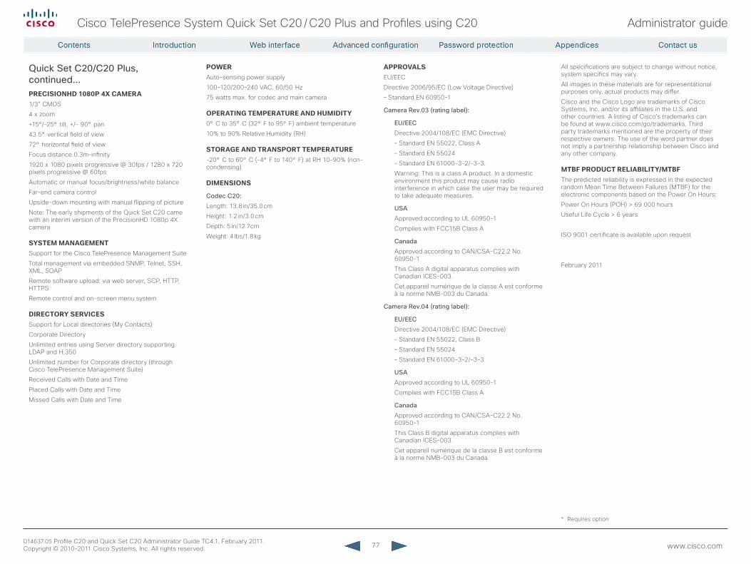
77
Cisco TelePresence System Quick Set C20 / C20 Plus and Profiles using C20 Administrator guide
D14637.05 Profile C20 and Quick Set C20 Administrator Guide TC4.1, February 2011. Copyright © 2010-2011 Cisco Systems, Inc. All rights reserved. www.cisco.com
APPROVALSEU/EEC
Directive 2006/95/EC (Low Voltage Directive)
– Standard EN 60950-1
Camera rev.03 (rating label):
EU/EEC
Directive 2004/108/EC (EMC Directive)
– Standard EN 55022, Class A
– Standard EN 55024
– Standard EN 61000-3-2/-3-3.
Warning: This is a class A product. In a domestic environment this product may cause radio interference in which case the user may be required to take adequate measures.
USA
Approved according to UL 60950-1
Complies with FCC15B Class A
Canada
Approved according to CAN/CSA-C22.2 No. 60950-1
This Class A digital apparatus complies with Canadian ICES-003.
Cet appareil numérique de la classe A est conforme à la norme NMB-003 du Canada.
Camera rev.04 (rating label):
EU/EEC
Directive 2004/108/EC (EMC Directive)
– Standard EN 55022, Class B
– Standard EN 55024
– Standard EN 61000-3-2/-3-3
USA
Approved according to UL 60950-1
Complies with FCC15B Class A
Canada
Approved according to CAN/CSA-C22.2 No. 60950-1
This Class B digital apparatus complies with Canadian ICES-003.
Cet appareil numérique de la classe B est conforme à la norme NMB-003 du Canada.
All specifications are subject to change without notice, system specifics may vary.
All images in these materials are for representational purposes only, actual products may differ.
Cisco and the Cisco Logo are trademarks of Cisco Systems, Inc. and/or its affiliates in the U.S. and other countries. A listing of Cisco’s trademarks can be found at www.cisco.com/go/trademarks. Third party trademarks mentioned are the property of their respective owners. The use of the word partner does not imply a partnership relationship between Cisco and any other company.
MTBFPRODUCTRELIABILITY/MTBFThe predicted reliability is expressed in the expected random Mean Time Between Failures (MTBF) for the electronic components based on the Power On Hours:
Power On Hours (POH) > 69 000 hours
Useful Life Cycle > 6 years
ISO 9001 certificate is available upon request
February 2011
POWERAuto-sensing power supply
100-120/200-240 VAC, 60/50 Hz
75 watts max. for codec and main camera
OPERATINGTEMPERATUREANDHUMIDITY0° C to 35° C (32° F to 95° F) ambient temperature
10% to 90% Relative Humidity (RH)
STORAGEANDTRANSPORTTEMPERATURE-20° C to 60° C (-4° F to 140° F) at RH 10–90% (non-condensing)
DIMENSIONS
Codec C20:
Length: 13.8 in/35.0 cm
Height: 1.2 in/3.0 cm
Depth: 5 in/12.7 cm
Weight: 4 lbs/1.8 kg
PRECISIONHD1080P4XCAMERA1/3” CMOS
4 x zoom
+15°/-25° tilt, +/- 90° pan
43.5° vertical field of view
72° horizontal field of view
Focus distance 0.3m–infinity
1920 x 1080 pixels progressive @ 30fps / 1280 x 720 pixels progressive @ 60fps
Automatic or manual focus/brightness/white balance
Far-end camera control
Upside-down mounting with manual flipping of picture
Note: The early shipments of the Quick Set C20 came with an interim version of the PrecisionHD 1080p 4X camera
SYSTEMMANAGEMENTSupport for the Cisco TelePresence Management Suite
Total management via embedded SNMP, Telnet, SSH, XML, SOAP
Remote software upload: via web server, SCP, HTTP, HTTPS
Remote control and on-screen menu system
DIRECTORYSERVICESSupport for Local directories (My Contacts)
Corporate Directory
Unlimited entries using Server directory supporting LDAP and H.350
Unlimited number for Corporate directory (through Cisco TelePresence Management Suite)
Received Calls with Date and Time
Placed Calls with Date and Time
Missed Calls with Date and Time
Quick Set C20/C20 Plus, continued...
* Requires option
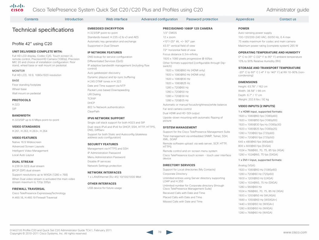
78
Cisco TelePresence System Quick Set C20 / C20 Plus and Profiles using C20 Administrator guide
D14637.05 Profile C20 and Quick Set C20 Administrator Guide TC4.1, February 2011. Copyright © 2010-2011 Cisco Systems, Inc. All rights reserved. www.cisco.com
Technical specifications
Profile 42” using C20
UNITDELIVEREDCOMPLETEWITH:Full HD LCD display, Codec C20, Touch screen UI, remote control, PrecisionHD Camera (1080p), Precision MIC 20 and choice of installation configuration: floor stand, wheel base or wall mount on pedestal.
MONITOr
Full HD LCD, 16:9, 1080x1920 resolution
BASE
Floor standing footplate
Wheel base
Wall mount on pedestal
PROTOCOLSH.323
SIP
BANDWIDTHH.323/SIP up to 6 Mbps point-to-point
VIDEOSTANDARDSH.261, H.263, H.263+, H.264
VIDEOFEATURESNative 16:9 Widescreen
Advanced Screen Layouts
Intelligent Video Management
Local Auto Layout
DUALSTREAMH.239 (H.323) dual stream
BFCP (SIP) dual stream
Support resolutions up to WXGA (1280 x 768)
When Dual video stream is activated the main video stream maximum is 720p 30fps
FIREWALLTRAVERSALCisco TelePresence ExpresswayTechnology
H.460.18, H.460.19 Firewall Traversal
EMBEDDEDENCRYPTIONH.323/SIP point-to-point
Standards-based: H.235 v2 & v3 and AES
Automatic key generation and exchange
Supported in Dual Stream
IPNETWORKFEATURESDNS lookup for service configuration
Differentiated Services (QoS)
IP adaptive bandwidth management (including flow control)
Auto gatekeeper discovery
Dynamic playout and lip-sync buffering
H.245 DTMF tones in H.323
Date and Time support via NTP
Packet Loss based Downspeeding
URI Dialing
TCP/IP
DHCP
802.1x Network authentication
ClearPath
IPV6NETWORKSUPPORTSingle call stack support for both H323 and SIP
Dual-stack IPv4 and IPv6 for DHCP, SSH, HTTP, HTTPS, DNS, DiffServ
Support for both Static and Autoconfig (stateless address auto configuration)
SECURITYFEATURESManagement via HTTPS and SSH
IP Administration Password
Menu Administration Password
Disable IP services
Network Settings protection
NETWORKINTERFACES1 x LAN/Ethernet (RJ-45) 10/100/1000 Mbit
OTHERINTERFACESUSB device for future usage
PRECISIONHD1080P12XCAMERA1/3” CMOS
12 x zoom
+15°/-25° tilt, +/- 90° pan
43.5° vertical field of view
72° horizontal field of view
Focus distance 0.3 m–infinity
1920 x 1080 pixels progressive @ 60fps
Other formats supported (configurable through Dip-switch):
1920 x 1080@60 Hz (HDMI only)
1920 x 1080@50 Hz (HDMI only)
1920 x 1080@30 Hz
1920 x 1080@25 Hz
1280 x 720@60 Hz
1280 x 720@50 Hz
1280 x 720@30 Hz
1280 x 720@25 Hz
Automatic or manual focus/brightness/white balance
Far-end camera control
Dual HDMI and HD-SDI output
Upside-down mounting with automatic flipping of picture
SYSTEMMANAGEMENTSupport for the Cisco TelePresence Management Suite
Total management via embedded SNMP, Telnet, SSH, XML, SOAP
Remote software upload: via web server, SCP, HTTP, HTTPS
Remote control and on-screen menu system
Cisco TelePresence touch screen - touch user interface device
DIRECTORYSERVICESSupport for Local directories (My Contacts)
Corporate Directory
Unlimited entries using Server directory supporting LDAP and H.350
Unlimited number for Corporate directory (through Cisco TelePresence Management Suite)
Received Calls with Date and Time
Placed Calls with Date and Time
Missed Calls with Date and Time
POWERAuto-sensing power supply
100-120/200-240 VAC, 60/50 Hz, 6 A max
75 watts maximum for codec and main camera
Maximum power rating (complete system) 265 W
OPERATINGTEMPERATUREANDHUMIDITY0° C to 35° C (32° F to 95° F) ambient temperature
10% to 90% Relative Humidity (RH)
STORAGEANDTRANSPORTTEMPERATURE-20° C to 60° C (-4° F to 140° F) at RH 10–90% (non-condensing)
DIMENSIONSHeight: 63.78” / 162 cm
Width: 38.58” / 98 cm
Depth: 6.7” / 17 cm
Weight: 202.8 lbs / 92 kg
VIDEOINPUTS(2INPUTS)
1 x HDMI input, supported formats:
1920 x 1080@60 fps (1080p60)
1920 x 1080@50 fps (1080p50)
1920 x 1080@30 fps Hz (1080p30)
1920 x 1080@25 fps (1080p25)
1280 x 720@60 fps (720p60)
1280 x 720@50 fps (720p50)
640 x 480@60 fps (480p60)
800 x 600@60 fps (SVGA)
1024 x 768@60, 70, 75, 85 fps (XGA)
1280 x 1024@60, 75 fps (SXGA)
1 x DVI-I input, supported formats:
Analog (VGA):
1920 x 1080@60 Hz (1080p60)
1280 x 720@60 Hz (720p60)
1600 x 1200@60 Hz (UXGA)
1280 x 1024@60, 75 Hz (SXGA)
1280 x 960@60 Hz
1024 x 768@60, 70, 75, 85 Hz (XGA)
1920 x 1200@50 Hz (WUXGA)
1680 x 1050@60 Hz (WSXGA+)
1440 x 900@60 Hz (WXGA+)
1280 x 800@60 Hz (WXGA)
1280 x 768@60 Hz (WXGA)
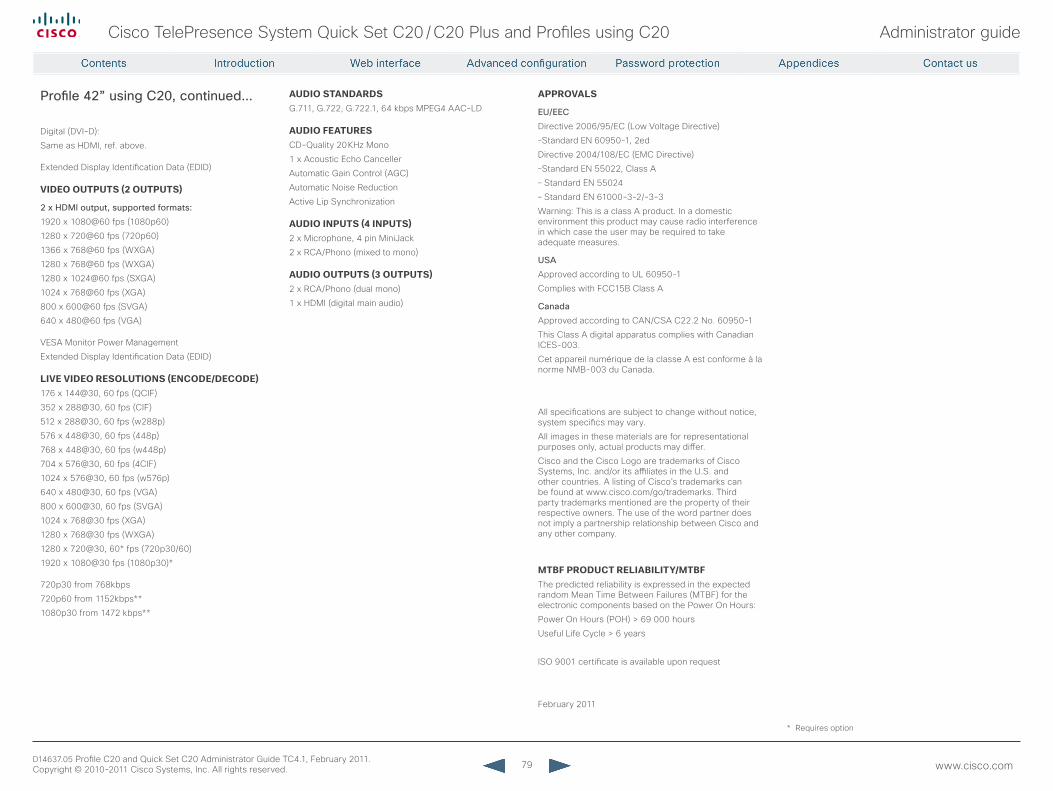
79
Cisco TelePresence System Quick Set C20 / C20 Plus and Profiles using C20 Administrator guide
D14637.05 Profile C20 and Quick Set C20 Administrator Guide TC4.1, February 2011. Copyright © 2010-2011 Cisco Systems, Inc. All rights reserved. www.cisco.com
APPROVALS
EU/EEC
Directive 2006/95/EC (Low Voltage Directive)
–Standard EN 60950-1, 2ed
Directive 2004/108/EC (EMC Directive)
–Standard EN 55022, Class A
– Standard EN 55024
– Standard EN 61000-3-2/-3-3
Warning: This is a class A product. In a domestic environment this product may cause radio interference in which case the user may be required to take adequate measures.
USA
Approved according to UL 60950-1
Complies with FCC15B Class A
Canada
Approved according to CAN/CSA C22.2 No. 60950-1
This Class A digital apparatus complies with Canadian ICES-003.
Cet appareil numérique de la classe A est conforme à la norme NMB-003 du Canada.
All specifications are subject to change without notice, system specifics may vary.
All images in these materials are for representational purposes only, actual products may differ.
Cisco and the Cisco Logo are trademarks of Cisco Systems, Inc. and/or its affiliates in the U.S. and other countries. A listing of Cisco’s trademarks can be found at www.cisco.com/go/trademarks. Third party trademarks mentioned are the property of their respective owners. The use of the word partner does not imply a partnership relationship between Cisco and any other company.
MTBFPRODUCTRELIABILITY/MTBFThe predicted reliability is expressed in the expected random Mean Time Between Failures (MTBF) for the electronic components based on the Power On Hours:
Power On Hours (POH) > 69 000 hours
Useful Life Cycle > 6 years
ISO 9001 certificate is available upon request
February 2011
AUDIOSTANDARDSG.711, G.722, G.722.1, 64 kbps MPEG4 AAC-LD
AUDIOFEATURESCD-Quality 20 KHz Mono
1 x Acoustic Echo Canceller
Automatic Gain Control (AGC)
Automatic Noise Reduction
Active Lip Synchronization
AUDIOINPUTS(4INPUTS)2 x Microphone, 4 pin MiniJack
2 x RCA/Phono (mixed to mono)
AUDIOOUTPUTS(3OUTPUTS)2 x RCA/Phono (dual mono)
1 x HDMI (digital main audio)
Digital (DVI-D):
Same as HDMI, ref. above.
Extended Display Identification Data (EDID)
VIDEOOUTPUTS(2OUTPUTS)
2 x HDMI output, supported formats:
1920 x 1080@60 fps (1080p60)
1280 x 720@60 fps (720p60)
1366 x 768@60 fps (WXGA)
1280 x 768@60 fps (WXGA)
1280 x 1024@60 fps (SXGA)
1024 x 768@60 fps (XGA)
800 x 600@60 fps (SVGA)
640 x 480@60 fps (VGA)
VESA Monitor Power Management
Extended Display Identification Data (EDID)
LIVEVIDEORESOLUTIONS(ENCODE/DECODE)176 x 144@30, 60 fps (QCIF)
352 x 288@30, 60 fps (CIF)
512 x 288@30, 60 fps (w288p)
576 x 448@30, 60 fps (448p)
768 x 448@30, 60 fps (w448p)
704 x 576@30, 60 fps (4CIF)
1024 x 576@30, 60 fps (w576p)
640 x 480@30, 60 fps (VGA)
800 x 600@30, 60 fps (SVGA)
1024 x 768@30 fps (XGA)
1280 x 768@30 fps (WXGA)
1280 x 720@30, 60* fps (720p30/60)
1920 x 1080@30 fps (1080p30)*
720p30 from 768kbps
720p60 from 1152kbps**
1080p30 from 1472 kbps**
Profile 42” using C20, continued...
* Requires option
80
Cisco TelePresence System Quick Set C20 / C20 Plus and Profiles using C20 Administrator guide
D14637.05 Profile C20 and Quick Set C20 Administrator Guide TC4.1, February 2011. Copyright © 2010-2011 Cisco Systems, Inc. All rights reserved. www.cisco.com
On our web site you will find an overview of the worldwide Cisco contacts.Go to: http://www.cisco.com/web/siteassets/contacts
Corporate HeadquartersCisco Systems, Inc.
170 West Tasman Dr.San Jose, CA 95134 USA
DisclaimerTHE SPECIFICATIONS AND INFORMATION REGARDING THE PRODUCTS IN THIS MANUAL ARE SUBJECT TO CHANGE WITHOUT NOTICE. ALL STATEMENTS, INFORMATION, AND
RECOMMENDATIONS IN THIS MANUAL ARE BELIEVED TO BE ACCURATE BUT ARE PRESENTED WITHOUT WARRANTY OF ANY KIND, EXPRESS OR IMPLIED. USERS MUST TAKE FULL RESPONSIBILITY FOR THEIR APPLICATION OF ANY PRODUCTS.
THE SOFTWARE LICENSE AND LIMITED WARRANTY FOR THE ACCOMPANYING PRODUCT ARE SET FORTH IN THE INFORMATION PACKET THAT SHIPPED WITH THE PRODUCT AND ARE INCORPORATED HEREIN BY THIS REFERENCE. IF YOU ARE UNABLE TO LOCATE THE SOFTWARE LICENSE OR LIMITED WARRANTY, CONTACT YOUR CISCO REPRESENTATIVE FOR A COPY.
The Cisco implementation of TCP header compression is an adaptation of a program developed by the University of California, Berkeley (UCB) as part of UCB’s public domain version of the UNIX operating system. All rights reserved. Copyright © 1981, Regents of the University of California.
NOTWITHSTANDING ANY OTHER WARRANTY HEREIN, ALL DOCUMENT FILES AND SOFTWARE OF THESE SUPPLIERS ARE PROVIDED “AS IS” WITH ALL FAULTS. CISCO AND THE ABOVE-NAMED SUPPLIERS DISCLAIM ALL WARRANTIES, EXPRESSED OR IMPLIED, INCLUDING, WITHOUT LIMITATION, THOSE OF MERCHANTABILITY, FITNESS FOR A PARTICULAR PURPOSE AND
NONINFRINGEMENT OR ARISING FROM A COURSE OF DEALING, USAGE, OR TRADE PRACTICE.IN NO EVENT SHALL CISCO OR ITS SUPPLIERS BE LIABLE FOR ANY INDIRECT, SPECIAL, CONSEQUENTIAL, OR INCIDENTAL DAMAGES, INCLUDING, WITHOUT LIMITATION, LOST PROFITS OR
LOSS OR DAMAGE TO DATA ARISING OUT OF THE USE OR INABILITY TO USE THIS MANUAL, EVEN IF CISCO OR ITS SUPPLIERS HAVE BEEN ADVISED OF THE POSSIBILITY OF SUCH DAMAGES.Cisco and the Cisco Logo are trademarks of Cisco Systems, Inc. and/or its affiliates in the U.S. and other countries. A listing of Cisco's trademarks can be found at www.cisco.com/go/trademarks.
Third party trademarks mentioned are the property of their respective owners. The use of the word partner does not imply a partnership relationship between Cisco and any other company. (1005R)Any Internet Protocol (IP) addresses and phone numbers used in this document are not intended to be actual addresses and phone numbers. Any examples, command display output, network
topology diagrams, and other figures included in the document are shown for illustrative purposes only. Any use of actual IP addresses or phone numbers in illustrative content is unintentional and coincidental.
TANDBERG is now a part of Cisco. TANDBERG® is a registered trademark belonging to Tandberg ASA.