cisco telepresence multipoint switch release 1.1 ...1 cisco telepresence multipoint switch release...
TRANSCRIPT
Americas HeadquartersCisco Systems, Inc.170 West Tasman DriveSan Jose, CA 95134-1706 USAhttp://www.cisco.comTel: 408 526-4000
800 553-NETS (6387)Fax: 408 527-0883
Cisco TelePresence Multipoint Switch Release 1.1 Administration GuideAugust 4, 2008
Customer Order Number: Text Part Number: OL-12586-02

THE SPECIFICATIONS AND INFORMATION REGARDING THE PRODUCTS IN THIS MANUAL ARE SUBJECT TO CHANGE WITHOUT NOTICE. ALL STATEMENTS, INFORMATION, AND RECOMMENDATIONS IN THIS MANUAL ARE BELIEVED TO BE ACCURATE BUT ARE PRESENTED WITHOUT WARRANTY OF ANY KIND, EXPRESS OR IMPLIED. USERS MUST TAKE FULL RESPONSIBILITY FOR THEIR APPLICATION OF ANY PRODUCTS.
THE SOFTWARE LICENSE AND LIMITED WARRANTY FOR THE ACCOMPANYING PRODUCT ARE SET FORTH IN THE INFORMATION PACKET THAT SHIPPED WITH THE PRODUCT AND ARE INCORPORATED HEREIN BY THIS REFERENCE. IF YOU ARE UNABLE TO LOCATE THE SOFTWARE LICENSE OR LIMITED WARRANTY, CONTACT YOUR CISCO REPRESENTATIVE FOR A COPY.
The Cisco implementation of TCP header compression is an adaptation of a program developed by the University of California, Berkeley (UCB) as part of UCB’s public domain version of the UNIX operating system. All rights reserved. Copyright © 1981, Regents of the University of California.
NOTWITHSTANDING ANY OTHER WARRANTY HEREIN, ALL DOCUMENT FILES AND SOFTWARE OF THESE SUPPLIERS ARE PROVIDED “AS IS” WITH ALL FAULTS. CISCO AND THE ABOVE-NAMED SUPPLIERS DISCLAIM ALL WARRANTIES, EXPRESSED OR IMPLIED, INCLUDING, WITHOUT LIMITATION, THOSE OF MERCHANTABILITY, FITNESS FOR A PARTICULAR PURPOSE AND NONINFRINGEMENT OR ARISING FROM A COURSE OF DEALING, USAGE, OR TRADE PRACTICE.
IN NO EVENT SHALL CISCO OR ITS SUPPLIERS BE LIABLE FOR ANY INDIRECT, SPECIAL, CONSEQUENTIAL, OR INCIDENTAL DAMAGES, INCLUDING, WITHOUT LIMITATION, LOST PROFITS OR LOSS OR DAMAGE TO DATA ARISING OUT OF THE USE OR INABILITY TO USE THIS MANUAL, EVEN IF CISCO OR ITS SUPPLIERS HAVE BEEN ADVISED OF THE POSSIBILITY OF SUCH DAMAGES.
CCDE, CCENT, Cisco Eos, Cisco StadiumVision, the Cisco logo, DCE, and Welcome to the Human Network are trademarks; Changing the Way We Work, Live, Play, andLearn is a service mark; and Access Registrar, Aironet, AsyncOS, Bringing the Meeting To You, Catalyst, CCDA, CCDP, CCIE, CCIP, CCNA, CCNP, CCSP, CCVP, Cisco,the Cisco Certified Internetwork Expert logo, Cisco IOS, Cisco Press, Cisco Systems, Cisco Systems Capital, the Cisco Systems logo, Cisco Unity, Collaboration WithoutLimitation, Enterprise/Solver, EtherChannel, EtherFast, EtherSwitch, Event Center, Fast Step, Follow Me Browsing, FormShare, GigaDrive, HomeLink, Internet Quotient,IOS, iPhone, iQ Expertise, the iQ logo, iQ Net Readiness Scorecard, iQuick Study, IronPort, the IronPort logo, LightStream, Linksys, MediaTone, MeetingPlace, MGX,Networkers, Networking Academy, Network Registrar, PCNow, PIX, PowerPanels, ProConnect, ScriptShare, SenderBase, SMARTnet, Spectrum Expert, StackWise, TheFastest Way to Increase Your Internet Quotient, TransPath, WebEx, and the WebEx logo are registered trademarks of Cisco Systems, Inc. and/or its affiliates in the UnitedStates and certain other countries.
All other trademarks mentioned in this document or Website are the property of their respective owners. The use of the word partner does not imply a partnership relationship between Cisco and any other company. (0803R)
Any Internet Protocol (IP) addresses used in this document are not intended to be actual addresses. Any examples, command display output, and figures included in the document are shown for illustrative purposes only. Any use of actual IP addresses in illustrative content is unintentional and coincidental.
Cisco TelePresence Multipoint Switch Release 1.1 Administration Guide© 2008 Cisco Systems, Inc. All rights reserved.
1Cisco TelePresence Multipoint Switch Release 1.1 Administration Guide
OL-12586-02
C O N T E N T S
General Description 1-5
New in CTMS Release 1.1 1-6
Increase in the Number of Supported Segments 1-6
Cisco TelePresence Interoperability With Legacy Video Conferencing Devices 1-6
System Requirements 1-6
CTMS Administration Guide Organization 1-6
Obtaining Documentation, Obtaining Support, and Security Guidelines 1-7
Using CTMS Administration Software 1-9
Contents 1-9
Overview 1-9
Administrative Roles 1-10
User Interface 1-10
Header 1-11
System Status 1-11
Navigation Pane 1-12
Content Area 1-12
System Information 1-12
Configuring Cisco Unified Communications Manager for CTMS 2-13
Contents 2-13
Overview 2-13
Prerequisites 2-14
Logging into the Unified CM Administration Application 2-14
Creating a SIP Trunk Security Profile 2-14
Creating a SIP Trunk 2-15
Configuring a Route Pattern 2-16
Installing CTMS Administration Software 3-17
Contents 3-17
Prerequisites 3-17
Installing the CTMS Administration Software 3-18
Configuring CTMS Administration Software 4-21
Contents 4-21
Contents
2Cisco TelePresence Multipoint Switch Release 1.1 Administration Guide
OL-12586-02
Overview 4-21
System Settings 4-22
Editing IP Settings 4-22
Editing Access Settings 4-23
Configuring and Editing QoS Settings 4-24
Configuring and Editing Resource Management 4-28
Configuring and Editing SNMP Settings 4-29
Restarting CTMS 4-31
Importing and Exporting Files 4-32
Cisco Unified Communications Manager Settings 4-32
Configuring and Editing Unified CM Settings 4-33
Configuring and Editing SIP Profile Settings 4-33
Configuring and Editing Cisco TelePresence Manager Settings 4-35
Configuring and Editing Access Management 4-36
Upgrading Software Version 4-40
Interface Failover 4-41
Managing Meetings 5-43
Contents 5-43
Overview 5-43
Defining and Editing Default Settings 5-43
Creating and Editing Static Meetings 5-45
Ad Hoc Meetings 5-49
Creating and Editing Ad Hoc Meetings 5-49
Creating and Editing Meeting Templates 5-51
Viewing Scheduled Meetings 5-54
Viewing and Editing Active Meetings 5-55
Troubleshooting the CTMS System 6-59
Contents 6-59
Overview 6-59
Viewing CTMS Alarms and System Error Messages 6-60
Configuring the Severity Level of System Error Messages 6-62
Filtering the Log File Table Listings 6-63
Downloading Log Files 6-64
Troubleshooting Specific Issues 6-64
Contents
3Cisco TelePresence Multipoint Switch Release 1.1 Administration Guide
OL-12586-02
Monitoring CTMS System Processes 7-67
Contents 7-67
Overview 7-67
Monitoring System Status 7-68
Monitoring and Restarting System Processes 7-69
Viewing Call Statistics 7-70
Room Testing 7-72
Interoperability with Legacy Video Conferencing Devices 8-75
Contents 8-75
Overview 8-75
How Cisco TelePresence Interoperability Works 8-75
Benefits 8-77
Caveats 8-77
Prerequisites 8-78
Configuring Cisco TelePresence Interoperability 8-79
Configuring Unified CM for Cisco TelePresence Interoperability 8-79
Creating a SIP Trunk Security Profile 8-79
Creating a SIP Trunk 8-80
Configuring a Route Pattern 8-80
Configuring CUVC for Cisco TelePresence Interoperability 8-81
Configuring CTMS for Cisco TelePresence Interoperability 8-85
Creating Static Meetings in CTMS for Interoperability 8-85
Troubleshooting Cisco TelePresence Interoperability 8-88
Command Line Interface (CLI) Commands A-1
Tables of Contents A-1
Introduction A-1
Starting a CLI Session A-1
CLI Command Basics A-2
Ending a CLI Session A-2
CTMS CLI Commands A-2

Contents
4Cisco TelePresence Multipoint Switch Release 1.1 Administration Guide
OL-12586-02
5Cisco TelePresence Multipoint Switch Release 1.1 Administration Guide
OL-12586-02
Preface
Initial Release: May 5, 2008, OL-12586-02Last Revised: August 4, 2008
General DescriptionThe Cisco TelePresence Multipoint Switch (CTMS) is designed to support multipoint (multi-location) Cisco TelePresence meetings for up to 48 table segments (48 single-screen systems, 16 three-screen systems, or a mix of both) in a single meeting. Table 1 summarizes some of the features of the CTMS:
Table 1 CTMS Features
Feature Benefit
Scalability CTMS is designed to support small workgroup applications to large Cisco TelePresence multipoint meetings. Up to 48 table segments are supported.
Simple scheduling and “one-button-to-push” dialing
CTMS and integration to Cisco TelePresence System Manager (CTS-Manager) allows scheduling through the enterprise calendar (for example, Microsoft Outlook) and easy one-button-to-push call launch for both point-to-point and multipoint meetings.
Scheduled and non-scheduled meeting support
During an active meeting, the conference manager can add another party using the CTMS Administration software.
Audio add-on Audio only participants can be added to any multipoint meeting using the audio add-on feature supported by CTS endpoints.
Video switching Voice-activated site and segment video switching supported.
Video announce Upon joining the meeting, Cisco TelePresence rooms will be shown to all other rooms for two seconds. This prevents a muted room from joining without being noticed.
Comprehensive diagnostics Diagnostics features include system status information, alarms, downloadable error logs and Simple Network Management Protocol (SNMP) support.
Call detail records Call records provide meeting beginning and ending information as well as meeting participant details.
6Cisco TelePresence Multipoint Switch Release 1.1 Administration Guide
OL-12586-02
PrefaceNew in CTMS Release 1.1
New in CTMS Release 1.1
Increase in the Number of Supported SegmentsCTMS Release 1.1 now supports up to 48 table segments (48 single-screen systems, 16 three-screen systems, or a mix of both) in a single Cisco TelePresence conference.
Cisco TelePresence Interoperability With Legacy Video Conferencing DevicesCisco TelePresence is based on open standards, including SIP, H.264. AAC-LD and G.711. With Cisco TelePresence System (CTS) Release 1.3 and CTMS Release 1.1, Cisco TelePresence now supports interoperability between Cisco TelePresence systems and traditional video conferencing/video telephony endpoints using the Cisco Unified Video Conferencing 3500 series MCU (CUVC).
System Requirements• Cisco MCS-7845-H2 or MCS-7845-I2 Media Convergence Server
• Cisco TelePresence Manager, Release 1.3
• Cisco Unified Communications Manager (Unified CM), Release 6.0 or later
• Cisco TelePresence System software, Release 1.3
• CTS-1000 and/or CTS-3000 systems
CTMS Administration Guide OrganizationThe CTMS Administration Guide is organized into the following chapters:
• Chapter 1: “Using CTMS Administration Software”This section provides information about the CTMS Administration software interface
• Chapter 2: “Configuring Cisco Unified Communications Manager for CTMS”This section provides instructions on how to configure Cisco Unified Communications Manager (Unified CM) so that is supports CTMS functionality.
• Chapter 3: “Installing CTMS Administration Software”This section describes how to install the CTMS administration software on the Cisco MCS-7800 Series Media Convergence Server.
• Chapter 4: “Configuring CTMS Administration Software”This section provides information about configuring the initial CTMS system settings.
• Chapter 5: “Managing Meetings”This section describe how to set up and administer static and ad hoc meetings using CTMS Administration software.
• Chapter 6: “Monitoring CTMS System Processes”This section describes how to monitor the CTMS system processes using the tools available in CTMS.
7Cisco TelePresence Multipoint Switch Release 1.1 Administration Guide
OL-12586-02
PrefaceObtaining Documentation, Obtaining Support, and Security Guidelines
• Chapter 7: “Troubleshooting the CTMS System”This section describes how to view and categorize system error messages and alerts, and how to filter and download log files.
• Chapter 8: “Interoperability with Legacy Video Conferencing Devices”This section describes how to configure settings in Unified CM ,CTMS and Cisco Unified Video Conferencing MCUs (CUVC) to support Cisco TelePresence Interoperability.
• Appendix A: “Command Line Interface (CLI) Commands:This section includes CLI commands that can be used to configure CTMS.
Obtaining Documentation, Obtaining Support, and Security Guidelines
For information on obtaining documentation, obtaining support, providing documentation feedback, security guidelines, and also recommended aliases and general Cisco documents, see the monthly What’s New in Cisco Product Documentation, which also lists all new and revised Cisco technical documentation, at:
http://www.cisco.com/en/US/docs/general/whatsnew/whatsnew.html

8Cisco TelePresence Multipoint Switch Release 1.1 Administration Guide
OL-12586-02
PrefaceObtaining Documentation, Obtaining Support, and Security Guidelines
C H A P T E R
1-9Cisco TelePresence Multipoint Switch Release 1.1 Administration Guide
OL-12586-02
1Using CTMS Administration Software
Initial Release: May 5, 2008, OL-12586-02Last Revised: August 4, 2008
Contents• Overview, page 1-9
• User Interface, page 1-10
• System Information, page 1-12
OverviewAdministrators use the CTMS Administration software to configure, to maintain, to monitor and to troubleshoot multipoint switching. Administrative tasks include the following:
• Configuring system settings. These tasks include configuring general system settings, Cisco TelePresence Manager (CTS-Manager) settings, and access management settings (such as administrative roles), System settings tasks are described in “Chapter 4: Configuring CTMS Administration Software.”
• Managing meetings. These tasks include defining meeting templates, defining static and ad hoc meetings and managing active meetings, as well as being able to observe information about scheduled meetings. Meeting management tasks are described in “Chapter 5: Managing Meetings.”
• Monitoring the system. These tasks include restarting the system and monitoring a variety of system processes. System monitoring tasks are described in “Chapter 6: Monitoring CTMS System Processes.”
• Troubleshooting the system. These tasks include monitoring system errors and log files to determine the causes of system errors. Troubleshooting is described in “Chapter 7: Troubleshooting the CTMS System.”
Prior to configuring CTMS Administration software, you must configure Cisco Unified Communications Manager (Unified CM) to support multipoint switching. Unified CM for CTMS configuration tasks are described in “Chapter 2: Configuring Cisco Unified Communications Manager for CTMS.”
Installing CTMS Administration software is described in “Chapter 3: Installing CTMS Administration Software.”
1-10Cisco TelePresence Multipoint Switch Release 1.1 Administration Guide
OL-12586-02
Chapter 1 Using CTMS Administration Software User Interface
Administrative RolesCTMS administration software recognizes three different administrative roles; access to task folders is dependent on defined administrative roles.
• Administrators: Administrators have the authority to perform all tasks associated with CTMS, including configuring system settings, managing multipoint meetings, maintaining, monitoring and troubleshooting CTMS. Administrators have access to all folders in CTMS Administration software.
• Meeting Scheduler: Meeting Schedulers have the authority to perform multipoint meeting management tasks, such as defining meeting templates, and setting up (and breaking down, as necessary) ad hoc, static and scheduled meetings. Meeting Schedulers have access to the Meeting Management folder in CTMS Administration software.
• Diagnostic Technicians: Diagnostic Technicians have the authority to perform CTMS monitoring and troubleshooting tasks. Diagnostic Technicians have access to the Troubleshooting and Monitoring folders in CTMS Administration software.
Administrative role configuration is described in “Chapter 4: Configuring CTMS Administration Software.”
User InterfaceCTMS Administration software user interface is similar to the interface used in Cisco TelePresence System Administration software and Cisco TelePresence Manager software. The user interface is organized as follows:
• Header, page 1-11
• System Status, page 1-11
• Navigation Pane, page 1-12
• Content Area, page 1-12
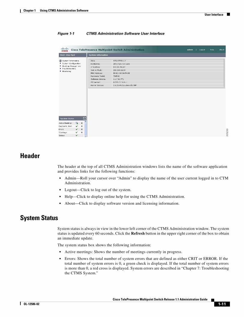
Figure 1-1 shows an example of the CTMS Administration software user interface.
1-11Cisco TelePresence Multipoint Switch Release 1.1 Administration Guide
OL-12586-02
Chapter 1 Using CTMS Administration Software User Interface
Figure 1-1 CTMS Administration Software User Interface
HeaderThe header at the top of all CTMS Administration windows lists the name of the software application and provides links for the following functions:
• Admin—Roll your cursor over “Admin” to display the name of the user current logged in to CTM Administration.
• Logout—Click to log out of the system.
• Help—Click to display online help for using the CTMS Administration.
• About—Click to display software version and licensing information.
System StatusSystem status is always in view in the lower left corner of the CTMS Administration window. The system status is updated every 60 seconds. Click the Refresh button in the upper right corner of the box to obtain an immediate update.
The system status box shows the following information:
• Active meetings: Shows the number of meetings currently in progress.
• Errors: Shows the total number of system errors that are defined as either CRIT or ERROR. If the total number of system errors is 0, a green check is displayed. If the total number of system errors is more than 0, a red cross is displayed. System errors are described in “Chapter 7: Troubleshooting the CTMS System.”
1-12Cisco TelePresence Multipoint Switch Release 1.1 Administration Guide
OL-12586-02
Chapter 1 Using CTMS Administration Software System Information
• Warnings: Shows the total number of system errors defined as WARN. If the total number of system errors is 0, a green check is displayed. If the total number of system errors is more than 0, a red cross is displayed. System warnings are described in “Chapter 7: Troubleshooting the CTMS System.”
• Status: Shows the current state of all system processes. If all system processes are in the RUNNING state, a green check is displayed. If one or more processes are in the STOPPED state, a red check is displayed. System processes are described in “Chapter 6: Monitoring CTMS System Processes.”
Navigation PaneIn the navigation pane at the left side of the CTMS Administration window, the System Configuration, Meeting Management, Troubleshooting, and Monitoring folders display lists of tasks associated with CTMS. Lists of tasks are also displayed in the content area of the window when you click any folder in the navigation pane. Click the task name or the arrows in the left panel, or click the highlighted name in the content area to navigate to tasks.
Content AreaThe right frame is the content area. When you select a folder or a task from the navigation pane, the content associated with that item displays in the content area. The gray bar above the content area shows the navigational path so you can quickly identify where you are at any time.
System InformationChoose System Information from the Navigation Pane to view information about the Cisco TelePresence Multipoint Switch. The information displayed under System Information is configured during CTMS software installation.
• SKU
• Hostname: Hostname of the CTMS.
• IP Address: IP address of the Cisco TelePresence Multipoint Switch.
• Hardware Model: Cisco MCS 7800 Series Media Convergence Server on which the Cisco TelePresence Multipoint Switch is running.
• Software Version: Version of CTMS Administration software currently installed.
C H A P T E R
2-13Cisco TelePresence Multipoint Switch Release 1.1 Administration Guide
OL-12586-02
2Configuring Cisco Unified Communications Manager for CTMS
Initial Release: May 5, 2008, OL-12586-02Last Revised: August 4, 2008
Contents• Overview, page 2-13
• Prerequisites, page 2-14
• Logging into the Unified CM Administration Application, page 2-14
• Creating a SIP Trunk Security Profile, page 2-14
• Creating a SIP Trunk, page 2-15
• Configuring a Route Pattern, page 2-16
• Configuring a Route Pattern, page 2-16
OverviewBefore installing the CTMS Administration software on your Cisco MCS-7845 Media Convergence Server, you need to perform the following configuration tasks in Cisco Unified Communications Manager (Unified CM):
• Create a SIP security profile. This security profile will be used on the SIP trunk between CTMS and Unified CM.
• Create a Session Initiation Protocol (SIP) trunk. The SIP trunk is used for communication between Unified CM and CTMS.
• Create route patterns. A route pattern comprises a string of digits (an address) and a set of associated digit manipulations that route calls to a route list or a gateway. Route patterns are used for routing conferences numbers to the CTMS.
2-14Cisco TelePresence Multipoint Switch Release 1.1 Administration Guide
OL-12586-02
Chapter 2 Configuring Cisco Unified Communications Manager for CTMS Prerequisites
PrerequisitesBefore starting the tasks in this chapter, make sure that the following conditions are met or that you understand the following information:
• Unified CM is running and using version 6.0 or later software.
• Cisco TelePresence System is running version 1.2.3 or later software. For interoperability with legacy video conferencing devices, Cisco TelePresence System must be running version 1.3 or later software.
For additional information about configuring Unified CM for Cisco TelePresence System, refer to the Cisco Unified Communications Manager Installation Guide for the Cisco TelePresence System.
Logging into the Unified CM Administration ApplicationTo log into the Unified CM Administration application:
Step 1 Open a web browser.
Step 2 Access a web browser that is supported by the Unified CM Administration application from any user PC in your network. In the address bar of the web browser, enter the following URL:
https://CUCM-server-name
where CUCM-server-name is the name or IP address of the server.
Note You may need to specify the address of the server where Unified CM is installed. If your network uses DNS services, you can specify the hostname of the server. If your network does not use DNS services, you must specify the IP address of the server.
Step 3 Log in with your assigned administrative privileges.
Step 4 Select Cisco Unified Communications Manager Administration in the Navigation field at the upper right corner of the page and click Go to return to the Cisco Unified Communications Manager Administration home page.
Creating a SIP Trunk Security ProfileTo create a SIP trunk security profile:
Step 1 Click System. Under Security Profile, click SIP Trunk Security Profile.
Step 2 Click the Add New button at the bottom of the page or click the + sign at the top of the page.
2-15Cisco TelePresence Multipoint Switch Release 1.1 Administration Guide
OL-12586-02
Chapter 2 Configuring Cisco Unified Communications Manager for CTMS Creating a SIP Trunk
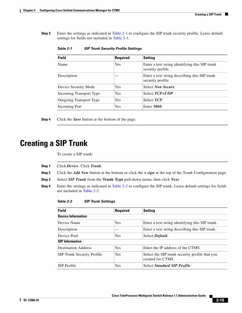
Step 3 Enter the settings as indicated in Table 2-1 to configure the SIP trunk security profile. Leave default settings for fields not included in Table 2-1..
Step 4 Click the Save button at the bottom of the page.
Creating a SIP TrunkTo create a SIP trunk:
Step 1 Click Device. Click Trunk.
Step 2 Click the Add New button at the bottom or click the + sign at the top of the Trunk Configuration page.
Step 3 Select SIP Trunk from the Trunk Type pull-down menu, then click Next.
Step 4 Enter the settings as indicated in Table 2-2 to configure the SIP trunk. Leave default settings for fields not included in Table 2-2..
Table 2-1 SIP Trunk Security Profile Settings
Field Required Setting
Name Yes Enter a text string identifying this SIP trunk security profile.
Description — Enter a text string describing this SIP trunk security profile.
Device Security Mode Yes Select Non Secure.
Incoming Transport Type Yes Select TCP+UDP.
Outgoing Transport Type Yes Select TCP.
Incoming Port Yes Enter 5060.
Table 2-2 SIP Trunk Settings
Field Required SettingDevice Information
Device Name Yes Enter a text string identifying this SIP trunk.
Description — Enter a text string describing this SIP trunk.
Device Pool Yes Select Default.SIP Information
Destination Address Yes Enter the IP address of the CTMS.
SIP Trunk Security Profile Yes Select the SIP trunk security profile that you created for CTMS.
SIP Profile Yes Select Standard SIP Profile.
2-16Cisco TelePresence Multipoint Switch Release 1.1 Administration Guide
OL-12586-02
Chapter 2 Configuring Cisco Unified Communications Manager for CTMS Configuring a Route Pattern
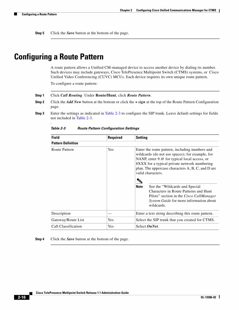
Step 5 Click the Save button at the bottom of the page.
Configuring a Route PatternA route pattern allows a Unified CM-managed device to access another device by dialing its number. Such devices may include gateways, Cisco TelePresence Multipoint Switch (CTMS) systems, or Cisco Unified Video Conferencing (CUVC) MCUs. Each device requires its own unique route pattern.
To configure a route pattern:
Step 1 Click Call Routing. Under Route/Hunt, click Route Pattern.
Step 2 Click the Add New button at the bottom or click the + sign at the top of the Route Pattern Configuration page.
Step 3 Enter the settings as indicated in Table 2-3 to configure the SIP trunk. Leave default settings for fields not included in Table 2-3..
Step 4 Click the Save button at the bottom of the page.
Table 2-3 Route Pattern Configuration Settings
Field Required SettingPattern Definition
Route Pattern Yes Enter the route pattern, including numbers and wildcards (do not use spaces); for example, for NANP, enter 9.@ for typical local access, or 8XXX for a typical private network numbering plan. The uppercase characters A, B, C, and D are valid characters.
Note See the “Wildcards and Special Characters in Route Patterns and Hunt Pilots” section in the Cisco CallManager System Guide for more information about wildcards.
Description — Enter a text string describing this route pattern.
Gateway/Route List Yes Select the SIP trunk that you created for CTMS.
Call Classification Yes Select OnNet.
C H A P T E R
3-17Cisco TelePresence Multipoint Switch Release 1.1 Administration Guide
OL-12586-02
3Installing CTMS Administration Software
Initial Release: May 5, 2008, OL-12586-02Last Revised: August 4, 2008
Contents• Prerequisites, page 3-17
• Installing the CTMS Administration Software, page 3-18
PrerequisitesBefore you install the Cisco TelePresence Multipoint Switch (CTMS) Administration software system files, you need the following equipment and information:
• Cisco TelePresence System (CTS)-1000 Release and/or CTS-3000 assembled and configured to support TelePresence conferencing. For more information, refer to the following guides:
– Cisco TelePresence System Release 1.3 Administrator's Guide
– Cisco TelePresence 3000 Assembly, Use & Care, and Field Replacement Unit Guide
– Cisco TelePresence 1000 Assembly, Use & Care, and Field Replacement Unit Guide
• Cisco MCS-7845-H2 or MCS-7845-I2 Media Convergence Server, installed and connected to a Domain Name System (DNS) server and your network.
• Console able to access the Cisco MCS-7845-H2 Series Media Convergence Server.
• DVD that contains the CTMS Administration software application.
• Cisco Unified Communications Manager (Unified CM) 6.0 or higher configured to support CTS Release 1.3 and integrated to work with CTMS, meaning that a SIP security profile, SIP trunk, and route pattern specific to CTMS have been created. For more information about Unified CM for CTS configuration, refer to Cisco Unified Communications Manager Installation Guide for the Cisco TelePresence System.
3-18Cisco TelePresence Multipoint Switch Release 1.1 Administration Guide
OL-12586-02
Chapter 3 Installing CTMS Administration Software Installing the CTMS Administration Software
Installing the CTMS Administration SoftwareTo install the CTMS Administration software application:
Step 1 Insert the CTMS Administration software application DVD into the appropriate drive in the Cisco MCS-7800 Series Media Convergence Server and boot up the host.
Step 2 Media Check: The system asks if you wish to perform a media check on the inserted DVD. Select Yes or No and press the Enter key. If you select No, the system bypasses the media check. If you select Yes, the system performs a checksum to make sure that the media on the DVD is intact. When the checksum has successfully completed, select Okay and press the Enter key.
Note If the checksum fails, it could be because of a problem with either the DVD or the DVD drive. The DVD or the DVD drive could need cleaning; the DVD data could be corrupted; or the software image you are trying to load could be the wrong image.
Step 3 Hard Drive Check: The system then checks the status of the hard drives in the server. When cued to update BIOS, press the Enter key to continue.
Step 4 Platform Installation Wizard: Select Proceed and press the Enter key to continue.
Step 5 Automatic Negotiation of Ethernet NIC Speed and Duplex: Select Yes and press the Enter key to continue.
Step 6 DHCP: Cisco Systems recommends that you use a static IP address instead of DHCP. Select No to define a specific static IP address and press the Enter key. Enter the following information:
• Hostname: Hostname of the CTMS server
• IP Address: IP address of the CTMS server
• IP Mask: Subnet mask for the CTMS server IP address
• Gateway Address: IP address for the gateway to the CTMS server
Select Okay and press the Enter key to continue.
Step 7 DNS Client: Select Yes and press the Enter key. Enter the following information:
• Primary DNS: IP address of the primary DNS server
• Secondary DNS: IP address of the secondary DNS server
• Domain: Domain name for your company
Select Okay and press the Enter key to continue.
Step 8 Platform Administrator Username and Password: Enter the following information:
• Administration ID
• Password
• Confirm Password
Select Okay and press the Enter key to continue.
Step 9 Certificate Information: Enter the following information:
• Organization
• Unit
• Location
3-19Cisco TelePresence Multipoint Switch Release 1.1 Administration Guide
OL-12586-02
Chapter 3 Installing CTMS Administration Software Installing the CTMS Administration Software
• State
• Country
Select Okay and press the Enter key to continue.
Step 10 Network Time Protocol (NTP) Client Information: Enter the following information:
• NTP Server 1: IP address of the primary NTP server
• NTP Server 2: IP address of the secondary NTP server
• NTP Server 3 through 5: IP addresses of additional NTP servers
Select Okay and press the Enter key to continue.
Note The NTP servers identified must be the same for CTMS, CTS and CTM. It is recommended that you provide at least three NTP servers.
Step 11 Platform Configuration Confirmation: Select Okay to continue with installation. select Back to go to previous screens in the installation procedure, or Cancel to abort the installation. When you have made your selection, press the Enter key. If you select Okay, platform and application installation takes approximately 30 to 45 minutes. During installation, allow the default selection for the custom kernal to proceed.
Step 12 After the CTMS Administration software application files have been installed, the system automatically reboots. The system then performs a check of the network connectivity and setup. If the system determines that any of the information you entered during the preceding steps is incorrect, a message is displayed on the console, giving the you the following options:
• Retry: Select this option (and press the Enter key) to retry the installation procedure.
• Review: Select this option (and press the Enter key) if you need to change any of the data you entered during the preceding installation steps. If you select this option, navigate to the appropriate installation data entry screen, re-enter the data, and then proceed to the Platform Configuration screen to re-initiate installation.
• Halt: Select this option (and press the Enter key) if you need to abort installation.
• Ignore: Select this option (and press the Enter key) to ignore the system warning.
Step 13 After the network connectivity and setup check, the system reboots again. Following this reboot, the CTMS Administration software log-on screen is displayed. Enter your username and password to continue with CTMS Administration software configuration.

3-20Cisco TelePresence Multipoint Switch Release 1.1 Administration Guide
OL-12586-02
Chapter 3 Installing CTMS Administration Software Installing the CTMS Administration Software

C H A P T E R
4-21Cisco TelePresence Multipoint Switch Release 1.1 Administration Guide
OL-12586-02
4Configuring CTMS Administration Software
Revised: June 6, 2008, OL-12586-02Last Revised: August 4, 2008
Contents• Overview, page 4-21
• System Settings, page 4-22
– Editing IP Settings, page 4-22
– Editing Access Settings, page 4-23
– Configuring and Editing QoS Settings, page 4-24
– Configuring and Editing Resource Management, page 4-28
• Cisco Unified Communications Manager Settings, page 4-32
– Configuring and Editing Unified CM Settings, page 4-33
– Configuring and Editing SIP Profile Settings, page 4-33
• Configuring and Editing Cisco TelePresence Manager Settings, page 4-35
• Configuring and Editing Access Management, page 4-36
• Upgrading Software Version, page 4-40
• Interface Failover, page 4-41
OverviewThe following sections describe the System Configuration parameters for the Cisco TelePresence Multipoint Switch (CTMS). System Configuration is divided into the following areas:
• System Settings, page 4-22
• Cisco Unified Communications Manager Settings, page 4-32
• Configuring and Editing Cisco TelePresence Manager Settings, page 4-35
• Configuring and Editing Access Management, page 4-36
4-22Cisco TelePresence Multipoint Switch Release 1.1 Administration Guide
OL-12586-02
Chapter 4 Configuring CTMS Administration Software System Settings
System SettingsSystem Settings are initially configured during Cisco TelePresence Multipoint Switch (CTMS) Administration software set up. Use the System Settings to make changes to these initial settings. System Settings consists of four configuration areas:
• Editing IP Settings, page 4-22
• Editing Access Settings, page 4-23
• Configuring and Editing QoS Settings, page 4-24
• Configuring and Editing Resource Management, page 4-28
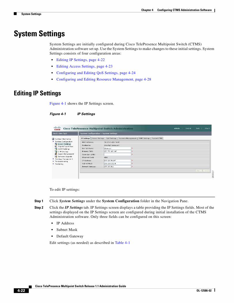
Editing IP SettingsFigure 4-1 shows the IP Settings screen.
Figure 4-1 IP Settings
To edit IP settings:
Step 1 Click System Settings under the System Configuration folder in the Navigation Pane.
Step 2 Click the IP Settings tab. IP Settings screen displays a table providing the IP Settings fields. Most of the settings displayed on the IP Settings screen are configured during initial installation of the CTMS Administration software. Only three fields can be configured on this screen:
• IP Address
• Subnet Mask
• Default Gateway
Edit settings (as needed) as described in Table 4-1
4-23Cisco TelePresence Multipoint Switch Release 1.1 Administration Guide
OL-12586-02
Chapter 4 Configuring CTMS Administration Software System Settings
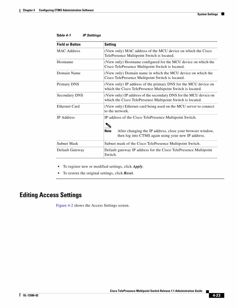
• To register new or modified settings, click Apply.
• To restore the original settings, click Reset.
Editing Access SettingsFigure 4-2 shows the Access Settings screen.
Table 4-1 IP Settings
Field or Button Setting
MAC Address (View only) MAC address of the MCU device on which the Cisco TelePresence Multipoint Switch is located.
Hostname (View only) Hostname configured for the MCU device on which the Cisco TelePresence Multipoint Switch is located.
Domain Name (View only) Domain name in which the MCU device on which the Cisco TelePresence Multipoint Switch is located.
Primary DNS (View only) IP address of the primary DNS for the MCU device on which the Cisco TelePresence Multipoint Switch is located.
Secondary DNS (View only) IP address of the secondary DNS for the MCU device on which the Cisco TelePresence Multipoint Switch is located.
Ethernet Card (View only) Ethernet card being used on the MCU server to connect to the network.
IP Address IP address of the Cisco TelePresence Multipoint Switch.
Note After changing the IP address, close your browser window, then log into CTMS again using your new IP address.
Subnet Mask Subnet mask of the Cisco TelePresence Multipoint Switch.
Default Gateway Default gateway IP address for the Cisco TelePresence Multipoint Switch.
4-24Cisco TelePresence Multipoint Switch Release 1.1 Administration Guide
OL-12586-02
Chapter 4 Configuring CTMS Administration Software System Settings
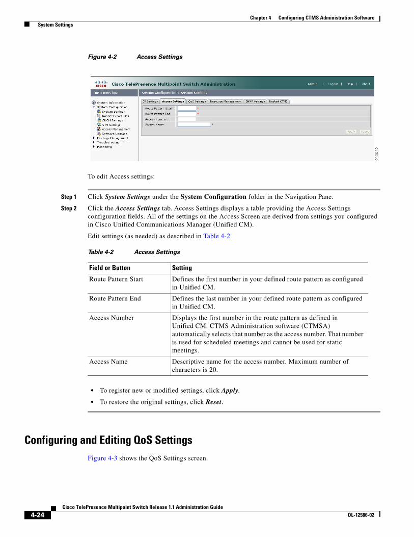
Figure 4-2 Access Settings
To edit Access settings:
Step 1 Click System Settings under the System Configuration folder in the Navigation Pane.
Step 2 Click the Access Settings tab. Access Settings displays a table providing the Access Settings configuration fields. All of the settings on the Access Screen are derived from settings you configured in Cisco Unified Communications Manager (Unified CM).
Edit settings (as needed) as described in Table 4-2
• To register new or modified settings, click Apply.
• To restore the original settings, click Reset.
Configuring and Editing QoS SettingsFigure 4-3 shows the QoS Settings screen.
Table 4-2 Access Settings
Field or Button Setting
Route Pattern Start Defines the first number in your defined route pattern as configured in Unified CM.
Route Pattern End Defines the last number in your defined route pattern as configured in Unified CM.
Access Number Displays the first number in the route pattern as defined in Unified CM. CTMS Administration software (CTMSA) automatically selects that number as the access number. That number is used for scheduled meetings and cannot be used for static meetings.
Access Name Descriptive name for the access number. Maximum number of characters is 20.
4-25Cisco TelePresence Multipoint Switch Release 1.1 Administration Guide
OL-12586-02
Chapter 4 Configuring CTMS Administration Software System Settings
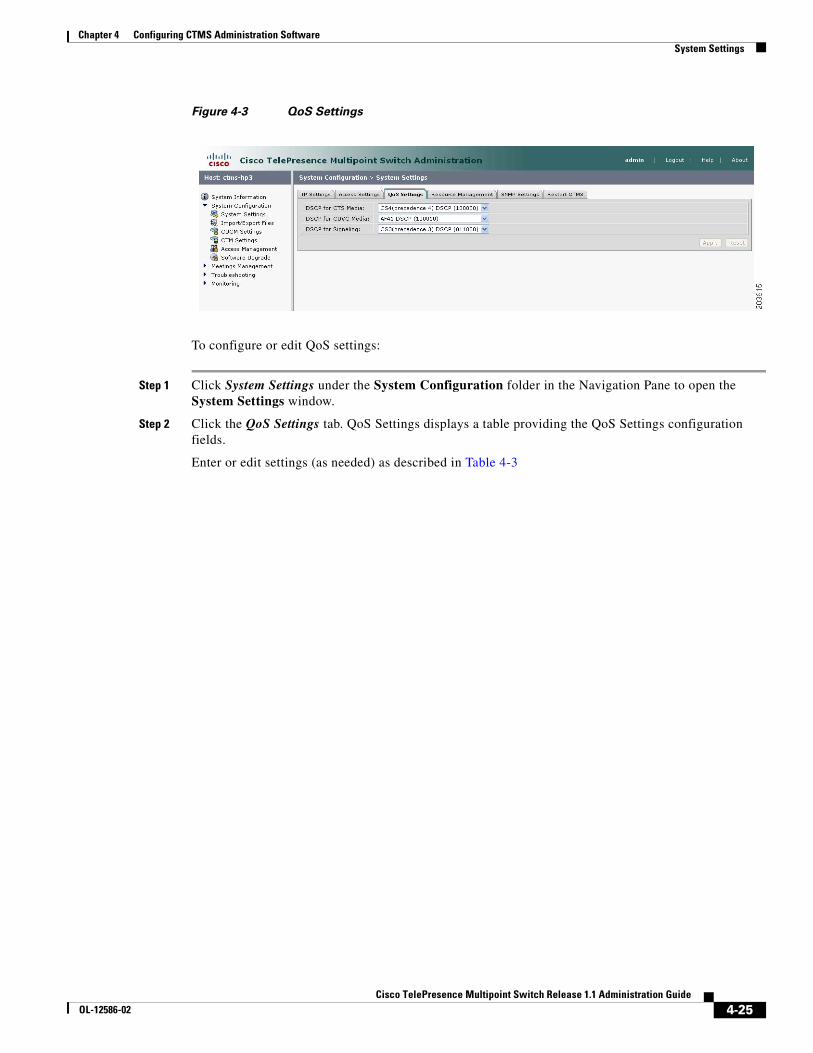
Figure 4-3 QoS Settings
To configure or edit QoS settings:
Step 1 Click System Settings under the System Configuration folder in the Navigation Pane to open the System Settings window.
Step 2 Click the QoS Settings tab. QoS Settings displays a table providing the QoS Settings configuration fields.
Enter or edit settings (as needed) as described in Table 4-3

4-26Cisco TelePresence Multipoint Switch Release 1.1 Administration Guide
OL-12586-02
Chapter 4 Configuring CTMS Administration Software System Settings
Table 4-3 QoS Settings
Field or Button Setting
DSCP for Media Traffic marking values for voice and video traffic used for network queuing. Available settings are:
• AF11 DSCP (001010)
• AF12 DSCP (001100)
• AF13 DSCP (001110)
• AF21 DSCP (010010)
• AF22 DSCP (010100)
• AF23 DSCP (010110)
• AF31 DSCP (011010)
• AF32 DSCP (011100)
• AF33 DSCP (011110)
• AF41 DSCP (100010)
• AF42 DSCP (100100)
• AF43 DSCP (100110)
• CS1 (precedence 1) DSCP (001000)
• CS2 (precedence 2) DSCP (010000)
• CS3 (precedence 3) DSCP (011000)
• CS4 (precedence 4) DSCP (100000)
• CS5 (precedence 5) DSCP (101000)
• CS6 (precedence 6) DSCP (110000)
• CS7 (precedence 7) DSCP (111000)
• Default DSCP (000000)
• EF DSCP (101110)
The default value for this field is CS4 (precedence 4) (100000). It is recommended that you use the default value for this field.
4-27Cisco TelePresence Multipoint Switch Release 1.1 Administration Guide
OL-12586-02
Chapter 4 Configuring CTMS Administration Software System Settings
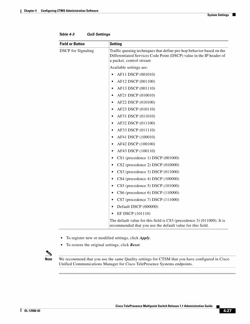
• To register new or modified settings, click Apply.
• To restore the original settings, click Reset.
Note We recommend that you use the same Quality settings for CTSM that you have configured in Cisco Unified Communications Manager for Cisco TelePresence Systems endpoints.
DSCP for Signaling Traffic queuing techniques that define per-hop behavior based on the Differentiated Services Code Point (DSCP) value in the IP header of a packet. control stream
Available settings are:
• AF11 DSCP (001010)
• AF12 DSCP (001100)
• AF13 DSCP (001110)
• AF21 DSCP (010010)
• AF22 DSCP (010100)
• AF23 DSCP (010110)
• AF31 DSCP (011010)
• AF32 DSCP (011100)
• AF33 DSCP (011110)
• AF41 DSCP (100010)
• AF42 DSCP (100100)
• AF43 DSCP (100110)
• CS1 (precedence 1) DSCP (001000)
• CS2 (precedence 2) DSCP (010000)
• CS3 (precedence 3) DSCP (011000)
• CS4 (precedence 4) DSCP (100000)
• CS5 (precedence 5) DSCP (101000)
• CS6 (precedence 6) DSCP (110000)
• CS7 (precedence 7) DSCP (111000)
• Default DSCP (000000)
• EF DSCP (101110)
The default value for this field is CS3 (precedence 3) (011000). It is recommended that you use the default value for this field.
Table 4-3 QoS Settings
Field or Button Setting
4-28Cisco TelePresence Multipoint Switch Release 1.1 Administration Guide
OL-12586-02
Chapter 4 Configuring CTMS Administration Software System Settings
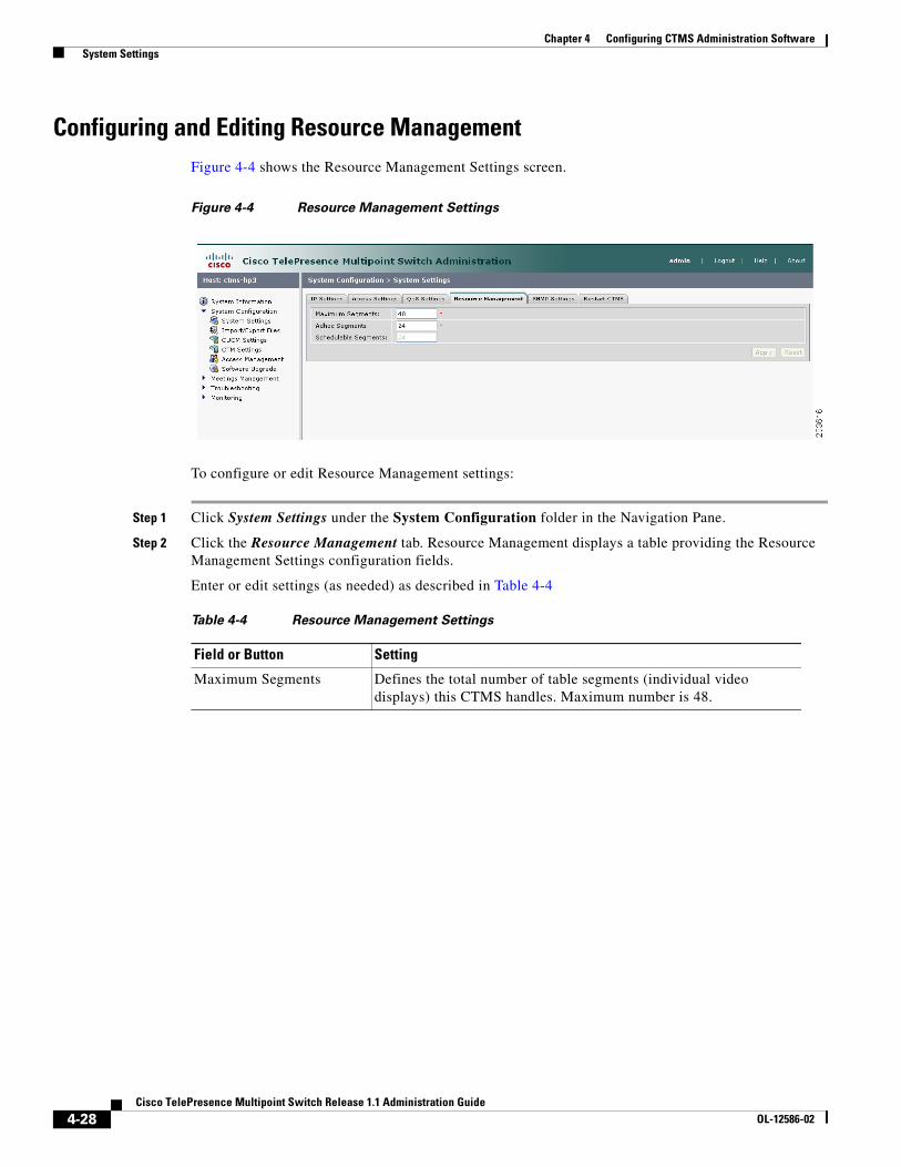
Configuring and Editing Resource ManagementFigure 4-4 shows the Resource Management Settings screen.
Figure 4-4 Resource Management Settings
To configure or edit Resource Management settings:
Step 1 Click System Settings under the System Configuration folder in the Navigation Pane.
Step 2 Click the Resource Management tab. Resource Management displays a table providing the Resource Management Settings configuration fields.
Enter or edit settings (as needed) as described in Table 4-4
Table 4-4 Resource Management Settings
Field or Button Setting
Maximum Segments Defines the total number of table segments (individual video displays) this CTMS handles. Maximum number is 48.
4-29Cisco TelePresence Multipoint Switch Release 1.1 Administration Guide
OL-12586-02
Chapter 4 Configuring CTMS Administration Software System Settings
Note If you do not have Cisco TelePresence Manager installed, all table segments must be ad hoc.
• To register new or modified settings, click Apply.
• To restore the original settings, click Reset.
Configuring and Editing SNMP SettingsThe Simple Network Management Protocol (SNMP) is an application layer protocol that facilitates the exchange of management information between network devices; it enables network administrators to manage network performance, find and solve network problems, and plan for network growth by analyzing information gathered using MIBs.
With SNMP for CTMS, you first enable (or disable) SNMP; when you enable SNMP, you turn on the SNMP daemon so CTMS is registered with SNMP (so that SNMP can begin monitoring CTMS and gathering data). You can also designate a particular server where SNMP trap messages are gathered and stored. Both of these configuration steps require separate username and password authentication.
By default, SNMP service is disabled. Once SNMP is enabled, the following default SNMP settings are also enabled:
• One SNMP username set to “admin”. This name cannot be changed.
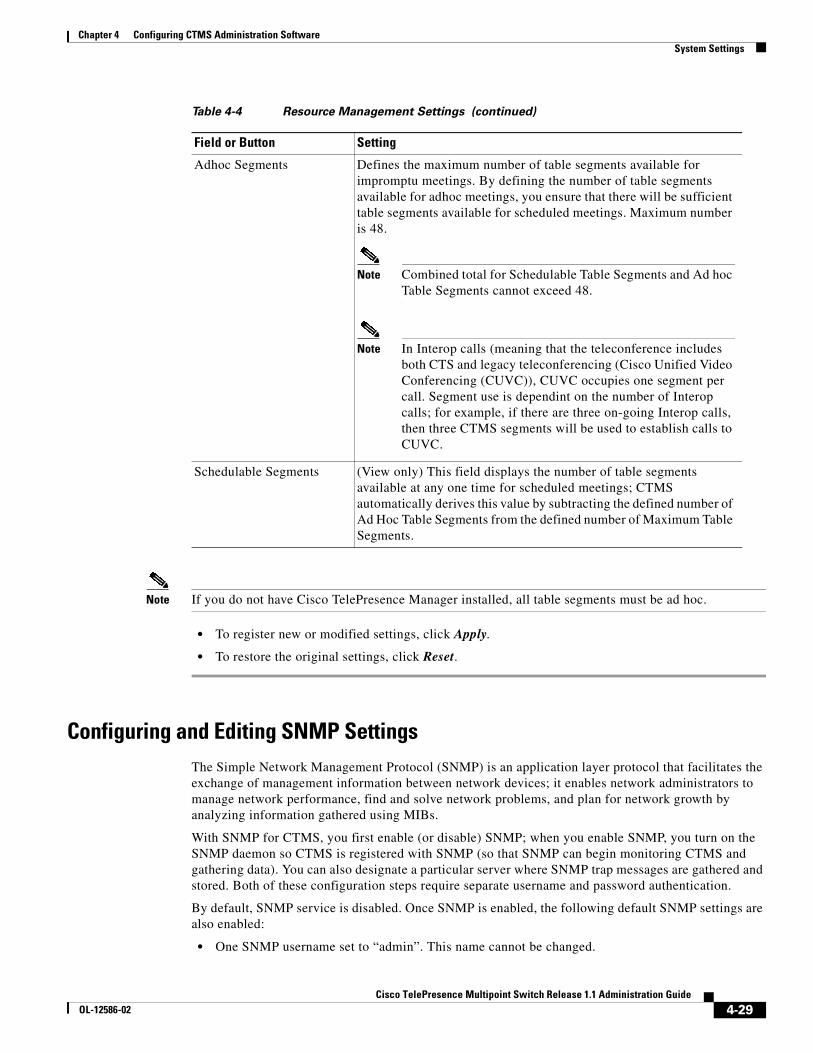
Adhoc Segments Defines the maximum number of table segments available for impromptu meetings. By defining the number of table segments available for adhoc meetings, you ensure that there will be sufficient table segments available for scheduled meetings. Maximum number is 48.
Note Combined total for Schedulable Table Segments and Ad hoc Table Segments cannot exceed 48.
Note In Interop calls (meaning that the teleconference includes both CTS and legacy teleconferencing (Cisco Unified Video Conferencing (CUVC)), CUVC occupies one segment per call. Segment use is dependint on the number of Interop calls; for example, if there are three on-going Interop calls, then three CTMS segments will be used to establish calls to CUVC.
Schedulable Segments (View only) This field displays the number of table segments available at any one time for scheduled meetings; CTMS automatically derives this value by subtracting the defined number of Ad Hoc Table Segments from the defined number of Maximum Table Segments.
Table 4-4 Resource Management Settings (continued)
Field or Button Setting
4-30Cisco TelePresence Multipoint Switch Release 1.1 Administration Guide
OL-12586-02
Chapter 4 Configuring CTMS Administration Software System Settings
• SNMP service password set to “snmppassword”. The password should be changed.
• No trap receiver configured. Use the Trap Receiver Configuration fields in this window to configure a trap receiver. The fields collect trap receiver username, password, authentication algorithm, hostname or IP address, and port.
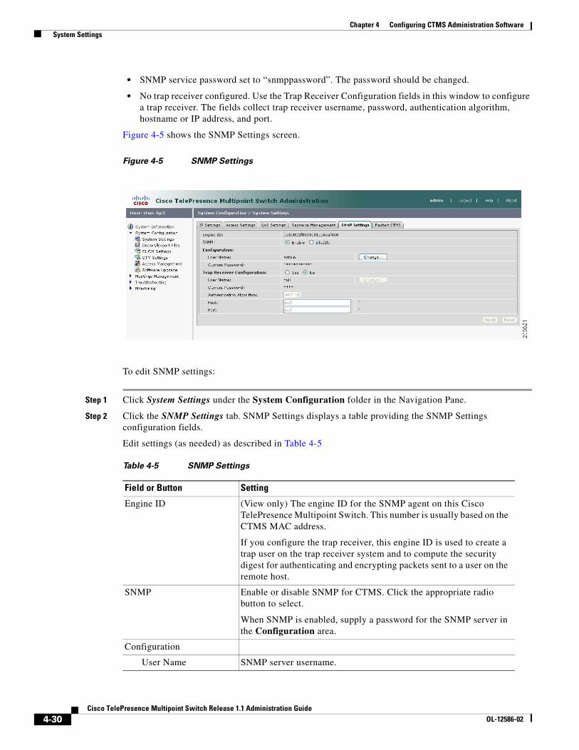
Figure 4-5 shows the SNMP Settings screen.
Figure 4-5 SNMP Settings
To edit SNMP settings:
Step 1 Click System Settings under the System Configuration folder in the Navigation Pane.
Step 2 Click the SNMP Settings tab. SNMP Settings displays a table providing the SNMP Settings configuration fields.
Edit settings (as needed) as described in Table 4-5
Table 4-5 SNMP Settings
Field or Button Setting
Engine ID (View only) The engine ID for the SNMP agent on this Cisco TelePresence Multipoint Switch. This number is usually based on the CTMS MAC address.
If you configure the trap receiver, this engine ID is used to create a trap user on the trap receiver system and to compute the security digest for authenticating and encrypting packets sent to a user on the remote host.
SNMP Enable or disable SNMP for CTMS. Click the appropriate radio button to select.
When SNMP is enabled, supply a password for the SNMP server in the Configuration area.
Configuration
User Name SNMP server username.

4-31Cisco TelePresence Multipoint Switch Release 1.1 Administration Guide
OL-12586-02
Chapter 4 Configuring CTMS Administration Software System Settings
• To register new or modified settings, click Apply.
• To restore the original settings, click Reset.
Restarting CTMSFigure 4-6 shows the Restart CTMS screen.
Figure 4-6 Restart CTMS Settings
To restart CTMS or to shutdown CTSM:
Step 1 Click System Settings under the System Configuration folder in the Navigation Pane.
Step 2 Click the Restart CTMS tab.
Step 3 Click Restart to restart—meaning shutdown and then reboot—CTMS.
Current Password SNMP server password. The password must be 8 characters long. Enter it twice for verification.
Trap Receiver Configuration
To select whether to use an SNMP trap receiver, click the Yes or No radio button, as appropriate.
When a trap receiver is used, supply login information for the trap receiver in the following fields.
User Name Trap receiver username.
Current Password Trap receiver password. The password must be 8 characters long. Enter it twice for verification.
Authentication Algorithm
Choose Message Digest 5 (MD5) or Secure Hash Algorithm (SHA) for authentication.
Table 4-5 SNMP Settings
Field or Button Setting
4-32Cisco TelePresence Multipoint Switch Release 1.1 Administration Guide
OL-12586-02
Chapter 4 Configuring CTMS Administration Software Importing and Exporting Files
Step 4 Click Shutdown to completely shutdown CTMS.
Importing and Exporting FilesImport/Export Files enables you to reuse previously defined user and configuration files (such as meeting templates) when upgrading to a new version of CTMS Administration Software. To reuse previously defined user and configuration files, you must first export the files to a secure location, upgrade to the new version of CTMS Administration software, and then import the files.
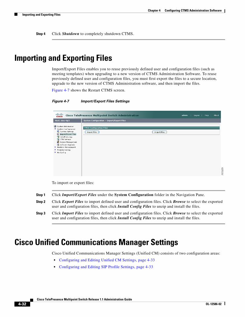
Figure 4-7 shows the Restart CTMS screen.
Figure 4-7 Import/Export Files Settings
To import or export files:
Step 1 Click Import/Export Files under the System Configuration folder in the Navigation Pane.
Step 2 Click Export Files to import defined user and configuration files. Click Browse to select the exported user and configuration files, then click Install Config Files to unzip and install the files.
Step 3 Click Import Files to import defined user and configuration files. Click Browse to select the exported user and configuration files, then click Install Config Files to unzip and install the files.
Cisco Unified Communications Manager SettingsCisco Unified Communications Manager Settings (Unified CM) consists of two configuration areas:
• Configuring and Editing Unified CM Settings, page 4-33
• Configuring and Editing SIP Profile Settings, page 4-33
4-33Cisco TelePresence Multipoint Switch Release 1.1 Administration Guide
OL-12586-02
Chapter 4 Configuring CTMS Administration Software Cisco Unified Communications Manager Settings
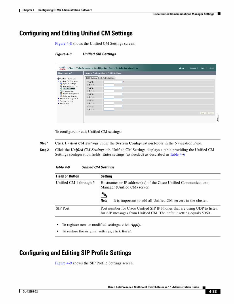
Configuring and Editing Unified CM SettingsFigure 4-8 shows the Unified CM Settings screen.
Figure 4-8 Unified CM Settings
To configure or edit Unified CM settings:
Step 1 Click Unified CM Settings under the System Configuration folder in the Navigation Pane.
Step 2 Click the Unified CM Settings tab. Unified CM Settings displays a table providing the Unified CM Settings configuration fields. Enter settings (as needed) as described in Table 4-6
• To register new or modified settings, click Apply.
• To restore the original settings, click Reset.
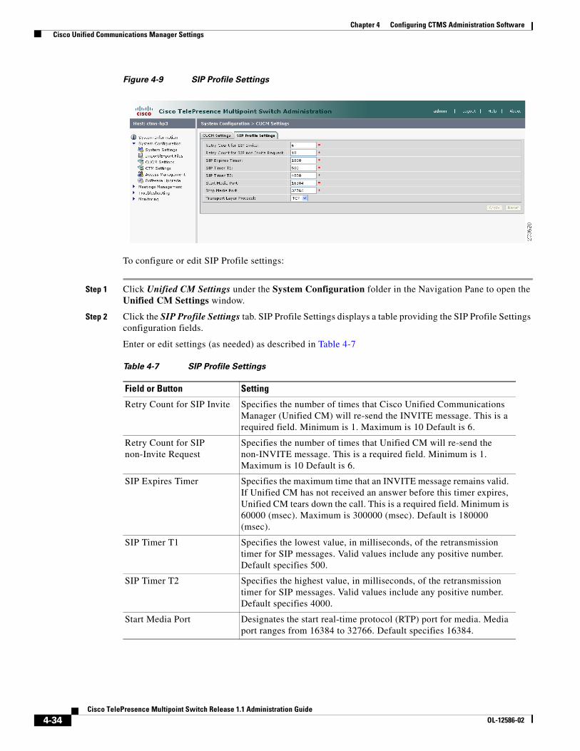
Configuring and Editing SIP Profile SettingsFigure 4-9 shows the SIP Profile Settings screen.
Table 4-6 Unified CM Settings
Field or Button Setting
Unified CM 1 through 5 Hostnames or IP address(es) of the Cisco Unified Communications Manager (Unified CM) server.
Note It is important to add all Unified CM servers in the cluster.
SIP Port Port number for Cisco Unified SIP IP Phones that are using UDP to listen for SIP messages from Unified CM. The default setting equals 5060.
4-34Cisco TelePresence Multipoint Switch Release 1.1 Administration Guide
OL-12586-02
Chapter 4 Configuring CTMS Administration Software Cisco Unified Communications Manager Settings
Figure 4-9 SIP Profile Settings
To configure or edit SIP Profile settings:
Step 1 Click Unified CM Settings under the System Configuration folder in the Navigation Pane to open the Unified CM Settings window.
Step 2 Click the SIP Profile Settings tab. SIP Profile Settings displays a table providing the SIP Profile Settings configuration fields.
Enter or edit settings (as needed) as described in Table 4-7
Table 4-7 SIP Profile Settings
Field or Button Setting
Retry Count for SIP Invite Specifies the number of times that Cisco Unified Communications Manager (Unified CM) will re-send the INVITE message. This is a required field. Minimum is 1. Maximum is 10 Default is 6.
Retry Count for SIP non-Invite Request
Specifies the number of times that Unified CM will re-send the non-INVITE message. This is a required field. Minimum is 1. Maximum is 10 Default is 6.
SIP Expires Timer Specifies the maximum time that an INVITE message remains valid. If Unified CM has not received an answer before this timer expires, Unified CM tears down the call. This is a required field. Minimum is 60000 (msec). Maximum is 300000 (msec). Default is 180000 (msec).
SIP Timer T1 Specifies the lowest value, in milliseconds, of the retransmission timer for SIP messages. Valid values include any positive number. Default specifies 500.
SIP Timer T2 Specifies the highest value, in milliseconds, of the retransmission timer for SIP messages. Valid values include any positive number. Default specifies 4000.
Start Media Port Designates the start real-time protocol (RTP) port for media. Media port ranges from 16384 to 32766. Default specifies 16384.
4-35Cisco TelePresence Multipoint Switch Release 1.1 Administration Guide
OL-12586-02
Chapter 4 Configuring CTMS Administration Software Configuring and Editing Cisco TelePresence Manager Settings
• To register new or modified settings, click Apply.
• To restore the original settings, click Reset.
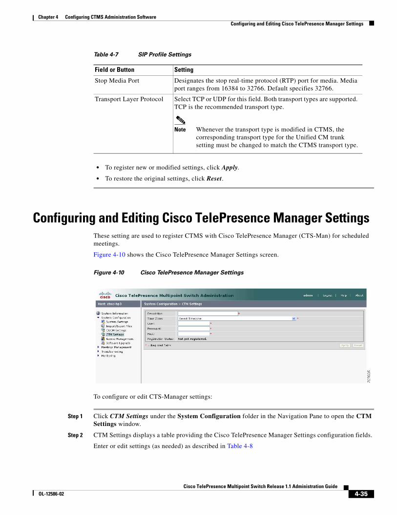
Configuring and Editing Cisco TelePresence Manager SettingsThese setting are used to register CTMS with Cisco TelePresence Manager (CTS-Man) for scheduled meetings.
Figure 4-10 shows the Cisco TelePresence Manager Settings screen.
Figure 4-10 Cisco TelePresence Manager Settings
To configure or edit CTS-Manager settings:
Step 1 Click CTM Settings under the System Configuration folder in the Navigation Pane to open the CTM Settings window.
Step 2 CTM Settings displays a table providing the Cisco TelePresence Manager Settings configuration fields.
Enter or edit settings (as needed) as described in Table 4-8
Stop Media Port Designates the stop real-time protocol (RTP) port for media. Media port ranges from 16384 to 32766. Default specifies 32766.
Transport Layer Protocol Select TCP or UDP for this field. Both transport types are supported. TCP is the recommended transport type.
Note Whenever the transport type is modified in CTMS, the corresponding transport type for the Unified CM trunk setting must be changed to match the CTMS transport type.
Table 4-7 SIP Profile Settings
Field or Button Setting
4-36Cisco TelePresence Multipoint Switch Release 1.1 Administration Guide
OL-12586-02
Chapter 4 Configuring CTMS Administration Software Configuring and Editing Access Management
• To register new or modified settings, click Apply.
• To restore the original settings, click Reset.
Configuring and Editing Access ManagementCTMS administration software recognizes three different administrative roles; access to task folders is dependent on defined administrative roles. So, administrative roles are considered a form of access management and are defined using Access Management settings.
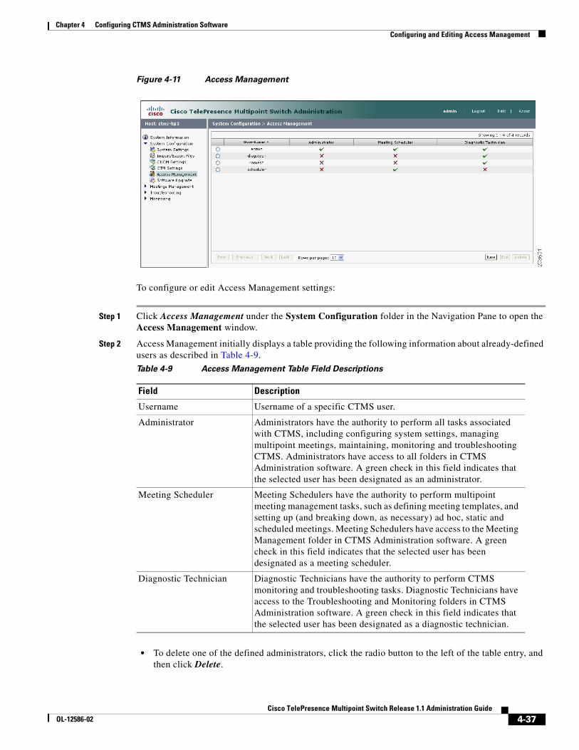
Figure 4-11 shows the Access Management screen.
Table 4-8 Cisco TelePresence Manager Settings
Field or Button Setting
Description Text describing or identifying this particular CTMS. The maximum number of characters for this field is 62 characters.
Time Zone Indicates the time zone in which the CTMS is located. Click “Time Zone” to display the list of available time zone options. Click option to highlight and select.
User Username with which CTMS web services communicates with CTS Manager.
Note Usernames must be at least 5 characters, but not more than 64 characters in length, and can contain upper and lower case alphanumeric characters and the underscore and dash characters. The following usernames are not allowed: apache, daemon, nobody, operator, and shutdown.
Note User name and password configured on the CTMS and CTS-Man need to be the same.
Password Password with which CTMS web services communicates with CTS Manager.
Note Passwords must be at least 5 characters, but not more than 64 characters in length, and can contain upper and lower case alphanumeric characters and the underscore and dash characters. The following usernames are not allowed: apache, daemon, nobody, operator, and shutdown.
Note User name and password configured on the CTMS and CTS-Man need to be the same.
Host Host is the IP address or host name of the CTS-Man.
Registration Status (View only) Registration state of the CTMS and CTS-Man.
4-37Cisco TelePresence Multipoint Switch Release 1.1 Administration Guide
OL-12586-02
Chapter 4 Configuring CTMS Administration Software Configuring and Editing Access Management
Figure 4-11 Access Management
To configure or edit Access Management settings:
Step 1 Click Access Management under the System Configuration folder in the Navigation Pane to open the Access Management window.
Step 2 Access Management initially displays a table providing the following information about already-defined users as described in Table 4-9.
• To delete one of the defined administrators, click the radio button to the left of the table entry, and then click Delete.
Table 4-9 Access Management Table Field Descriptions
Field Description
Username Username of a specific CTMS user.
Administrator Administrators have the authority to perform all tasks associated with CTMS, including configuring system settings, managing multipoint meetings, maintaining, monitoring and troubleshooting CTMS. Administrators have access to all folders in CTMS Administration software. A green check in this field indicates that the selected user has been designated as an administrator.
Meeting Scheduler Meeting Schedulers have the authority to perform multipoint meeting management tasks, such as defining meeting templates, and setting up (and breaking down, as necessary) ad hoc, static and scheduled meetings. Meeting Schedulers have access to the Meeting Management folder in CTMS Administration software. A green check in this field indicates that the selected user has been designated as a meeting scheduler.
Diagnostic Technician Diagnostic Technicians have the authority to perform CTMS monitoring and troubleshooting tasks. Diagnostic Technicians have access to the Troubleshooting and Monitoring folders in CTMS Administration software. A green check in this field indicates that the selected user has been designated as a diagnostic technician.

4-38Cisco TelePresence Multipoint Switch Release 1.1 Administration Guide
OL-12586-02
Chapter 4 Configuring CTMS Administration Software Configuring and Editing Access Management
• To edit one of the defined administrators, click the radio button to the left of the table entry, and then click Edit.
• To define a new administrator, click New,
Step 3 When you click New from the Access Management screen, CTMS Administration software takes you to the New User Settings table as shown in Figure 4-12.
Figure 4-12 New User Settings
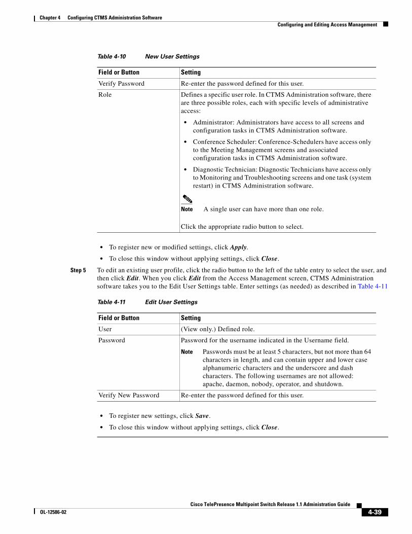
Step 4 Enter settings as described in Table 4-10
Table 4-10 New User Settings
Field or Button Setting
Username Username identifying a defined role as selected from the Role field.
Note Usernames must be at least 5 characters, but not more than 64 characters in length, and can contain upper and lower case alphanumeric characters and the underscore and dash characters. The following usernames are not allowed: apache, daemon, nobody, operator, and shutdown.
Password Password for the username indicated in the Username field.
Note Passwords must be at least 5 characters, but not more than 64 characters in length, and can contain upper and lower case alphanumeric characters and the underscore and dash characters. The following usernames are not allowed: apache, daemon, nobody, operator, and shutdown.
4-39Cisco TelePresence Multipoint Switch Release 1.1 Administration Guide
OL-12586-02
Chapter 4 Configuring CTMS Administration Software Configuring and Editing Access Management
• To register new or modified settings, click Apply.
• To close this window without applying settings, click Close.
Step 5 To edit an existing user profile, click the radio button to the left of the table entry to select the user, and then click Edit. When you click Edit from the Access Management screen, CTMS Administration software takes you to the Edit User Settings table. Enter settings (as needed) as described in Table 4-11
• To register new settings, click Save.
• To close this window without applying settings, click Close.
Verify Password Re-enter the password defined for this user.
Role Defines a specific user role. In CTMS Administration software, there are three possible roles, each with specific levels of administrative access:
• Administrator: Administrators have access to all screens and configuration tasks in CTMS Administration software.
• Conference Scheduler: Conference-Schedulers have access only to the Meeting Management screens and associated configuration tasks in CTMS Administration software.
• Diagnostic Technician: Diagnostic Technicians have access only to Monitoring and Troubleshooting screens and one task (system restart) in CTMS Administration software.
Note A single user can have more than one role.
Click the appropriate radio button to select.
Table 4-10 New User Settings
Field or Button Setting
Table 4-11 Edit User Settings
Field or Button Setting
User (View only.) Defined role.
Password Password for the username indicated in the Username field.
Note Passwords must be at least 5 characters, but not more than 64 characters in length, and can contain upper and lower case alphanumeric characters and the underscore and dash characters. The following usernames are not allowed: apache, daemon, nobody, operator, and shutdown.
Verify New Password Re-enter the password defined for this user.
4-40Cisco TelePresence Multipoint Switch Release 1.1 Administration Guide
OL-12586-02
Chapter 4 Configuring CTMS Administration Software Upgrading Software Version
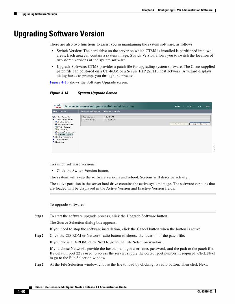
Upgrading Software VersionThere are also two functions to assist you in maintaining the system software, as follows:
• Switch Version: The hard drive on the server on which CTMS is installed is partitioned into two areas. Each area can contain a system image. Switch Version allows you to switch the location of two stored versions of the system software.
• Upgrade Software: CTMS provides a patch file for upgrading system software. The Cisco-supplied patch file can be stored on a CD-ROM or a Secure FTP (SFTP) host network. A wizard displays dialog boxes to prompt you through the process.
Figure 4-13 shows the Software Upgrade screen.
Figure 4-13 System Upgrade Screen
To switch software versions:
• Click the Switch Version button.
The system will swap the software versions and reboot. Screens will describe activity.
The active partition in the server hard drive contains the active system image. The software versions that are loaded will be displayed in the Active Version and Inactive Version fields.
To upgrade software:
Step 1 To start the software upgrade process, click the Upgrade Software button.
The Source Selection dialog box appears.
If you need to stop the software installation, click the Cancel button when the button is active.
Step 2 Click the CD-ROM or Network radio button to choose the location of the patch file.
If you chose CD-ROM, click Next to go to the File Selection window.
If you chose Network, provide the hostname, login username, password, and the path to the patch file. By default, port 22 is used to access the server; supply the correct port number, if required. Click Next to go to the File Selection window.
Step 3 At the File Selection window, choose the file to load by clicking its radio button. Then click Next.
4-41Cisco TelePresence Multipoint Switch Release 1.1 Administration Guide
OL-12586-02
Chapter 4 Configuring CTMS Administration Software Interface Failover
Step 4 The Patch File Preparation window appears. Watch this window to monitor the progress of the file download. Buttons will be inactive until the patch file is loaded.
Once the file is loaded, the window displays a Confirmation message.
The software wizard displays the software versions that are installed and provides active Yes and No radio buttons so you can choose to switch the newly loaded software to the active partition.
Step 5 Click Yes or No to make your choice. Then click Next to finish the software upgrade task.
The install wizard displays a dialog window that logs the progress of the update.
Step 6 When the log indicates that the files have been switched, click Finish to complete this task.
Interface FailoverInterface failover provides a backup mechanism for Ethernet adapters. When enabled, the secondary adapter handles all network traffic if the primary adapter or its connection fails.
To enable interface failover:
Step 1 Make sure that the primary Ethernet adapter (Ethernet interface 0) is connected to the network and that its static IP address and gateway parameters were correctly configured during system installation.
Step 2 Connect the secondary Ethernet cable (Ethernet interface 1) to a network switch. The connection port can be on the same switch as Ethernet interface 0 or on a different switch but both Ethernet interface 0 and Ethernet interface 1 must be on the same gateway.
Step 3 From the Interface Failover window, click the Enable button, then click Apply.
Note If the Enable button is grayed out, check your network connection.
To disable interface failover:
Step 1 With no active meetings in progress, click the Disable button.
Step 2 Click Apply. Your network adapters will be configured and restarted and the interface failover disabled.

4-42Cisco TelePresence Multipoint Switch Release 1.1 Administration Guide
OL-12586-02
Chapter 4 Configuring CTMS Administration Software Interface Failover
C H A P T E R
5-43Cisco TelePresence Multipoint Switch Release 1.1 Administration Guide
OL-12586-02
5Managing Meetings
Initial Release: May 5, 2008, OL-12586-02Last Revised: August 4, 2008
Contents• Overview, page 5-43
• Defining and Editing Default Settings, page 5-43
• Creating and Editing Static Meetings, page 5-45
• Ad Hoc Meetings, page 5-49
– Creating and Editing Ad Hoc Meetings, page 5-49
– Creating and Editing Meeting Templates, page 5-51
• Viewing Scheduled Meetings, page 5-54
• Viewing and Editing Active Meetings, page 5-55
OverviewThis chapter describes how to set up and administer static (reservationless) and ad hoc meetings using the CTMS Administration software.
Defining and Editing Default SettingsDefault settings are those that the CTMS Administration software automatically assigns to meeting profiles unless you configure specific settings for ad hoc and static meetings.
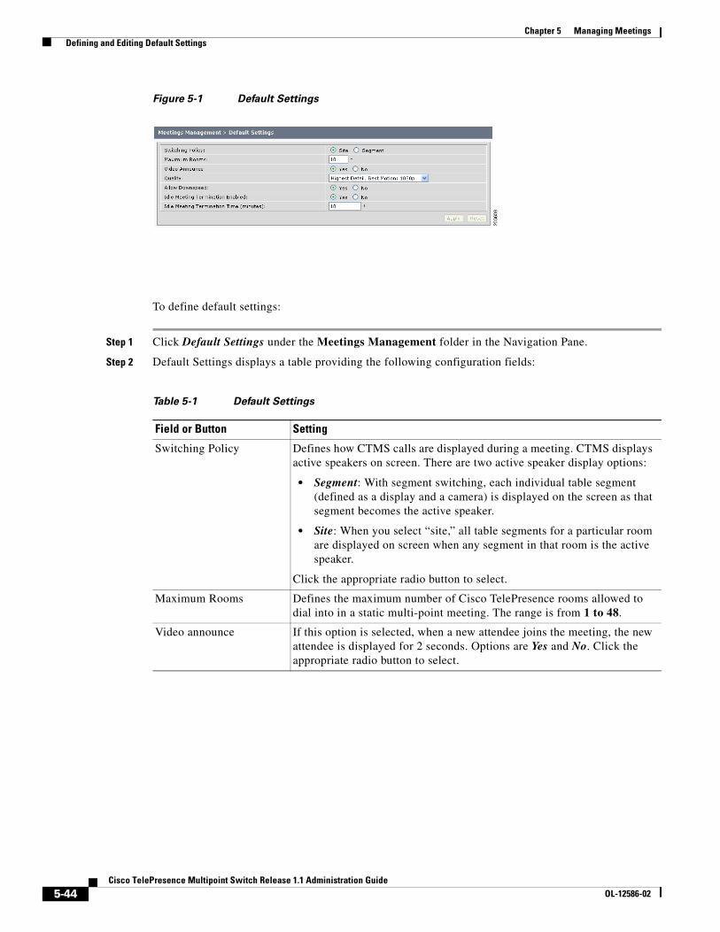
Figure 5-1 shows the Default Settings screen.
5-44Cisco TelePresence Multipoint Switch Release 1.1 Administration Guide
OL-12586-02
Chapter 5 Managing Meetings Defining and Editing Default Settings
Figure 5-1 Default Settings
To define default settings:
Step 1 Click Default Settings under the Meetings Management folder in the Navigation Pane.
Step 2 Default Settings displays a table providing the following configuration fields:
Table 5-1 Default Settings
Field or Button Setting
Switching Policy Defines how CTMS calls are displayed during a meeting. CTMS displays active speakers on screen. There are two active speaker display options:
• Segment: With segment switching, each individual table segment (defined as a display and a camera) is displayed on the screen as that segment becomes the active speaker.
• Site: When you select “site,” all table segments for a particular room are displayed on screen when any segment in that room is the active speaker.
Click the appropriate radio button to select.
Maximum Rooms Defines the maximum number of Cisco TelePresence rooms allowed to dial into in a static multi-point meeting. The range is from 1 to 48.
Video announce If this option is selected, when a new attendee joins the meeting, the new attendee is displayed for 2 seconds. Options are Yes and No. Click the appropriate radio button to select.

5-45Cisco TelePresence Multipoint Switch Release 1.1 Administration Guide
OL-12586-02
Chapter 5 Managing Meetings Creating and Editing Static Meetings
• To register new or modified settings, click Apply.
• To restore the original settings, click Reset.
Creating and Editing Static MeetingsStatic meetings are meetings that are permanently available after they have been configured. Each static meeting has its own associated meeting number; meetings attendees dial into that specific number when attending a static meeting. You can also add participants to a static meeting through the Active Meetings page.
Note Static meetings use ad hoc meeting resources.
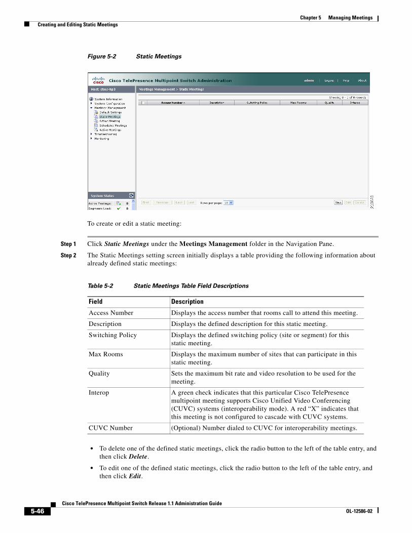
Figure 5-2 shows the Static Meetings screen.
Quality This field sets the system bandwidth and screen resolution. A higher bandwidth increases video quality, but may also cause packets to be dropped and video to be interrupted. Choices:
• Highest Detail, Best Motion: 4Mbps 1080p
• Highest Detail, Better Motion: 3.5Mbps, 1080p
• Highest Detail, Good Motion: 3Mbps, 1080p
• High Detail, Best Motion: 3Mbps, 720p
• High Detail, Better Motion: 2Mbps, 720p
• High Detail, Good Motion: 1Mbps, 720p
Default is Highest Detail, Best Motion: 4Mbps 1080p.
Allow Downspeed When selected, if an endpoint joins the meeting with a lower Quality value than other endpoints, the endpoint is allowed to join the meeting and all other endpoints downgrade their Quality to match the lower value. If this option is not selected, endpoints with a lower Quality value are not allowed to join the meeting.
Options are Yes and No. Click the appropriate radio button to select.
Idle Meeting Termination Enabled:
When selected, the meeting is terminated if the system does not detect an active speaker for the value set in the Idle Meeting Termination Time field.
Options are Yes and No. Click the appropriate radio button to select.
Idle Meeting Termination Time (minutes)
If the Idle Meeting Termination Enabled field is set to “Yes,” this field defines the number of minutes before a meeting is terminated (if the system does not detect an active speaker).
Possible values range from 1 to 59 minutes. The default is 10 minutes.
Table 5-1 Default Settings
Field or Button Setting
5-46Cisco TelePresence Multipoint Switch Release 1.1 Administration Guide
OL-12586-02
Chapter 5 Managing Meetings Creating and Editing Static Meetings
Figure 5-2 Static Meetings
To create or edit a static meeting:
Step 1 Click Static Meetings under the Meetings Management folder in the Navigation Pane.
Step 2 The Static Meetings setting screen initially displays a table providing the following information about already defined static meetings:
• To delete one of the defined static meetings, click the radio button to the left of the table entry, and then click Delete.
• To edit one of the defined static meetings, click the radio button to the left of the table entry, and then click Edit.
Table 5-2 Static Meetings Table Field Descriptions
Field Description
Access Number Displays the access number that rooms call to attend this meeting.
Description Displays the defined description for this static meeting.
Switching Policy Displays the defined switching policy (site or segment) for this static meeting.
Max Rooms Displays the maximum number of sites that can participate in this static meeting.
Quality Sets the maximum bit rate and video resolution to be used for the meeting.
Interop A green check indicates that this particular Cisco TelePresence multipoint meeting supports Cisco Unified Video Conferencing (CUVC) systems (interoperability mode). A red “X” indicates that this meeting is not configured to cascade with CUVC systems.
CUVC Number (Optional) Number dialed to CUVC for interoperability meetings.
5-47Cisco TelePresence Multipoint Switch Release 1.1 Administration Guide
OL-12586-02
Chapter 5 Managing Meetings Creating and Editing Static Meetings
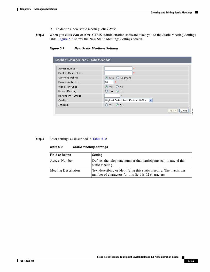
• To define a new static meeting, click New.
Step 3 When you click Edit or New, CTMS Administration software takes you to the Static Meeting Settings table. Figure 5-3 shows the New Static Meetings Settings screen.
Figure 5-3 New Static Meetings Settings
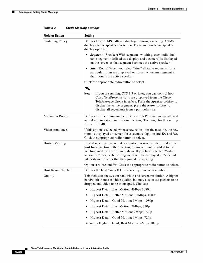
Step 4 Enter settings as described in Table 5-3:
Table 5-3 Static Meeting Settings
Field or Button Setting
Access Number Defines the telephone number that participants call to attend this static meeting.
Meeting Description Text describing or identifying this static meeting. The maximum number of characters for this field is 62 characters.
5-48Cisco TelePresence Multipoint Switch Release 1.1 Administration Guide
OL-12586-02
Chapter 5 Managing Meetings Creating and Editing Static Meetings
Switching Policy Defines how CTMS calls are displayed during a meeting. CTMS displays active speakers on screen. There are two active speaker display options:
• Segment: (Speaker) With segment switching, each individual table segment (defined as a display and a camera) is displayed on the screen as that segment becomes the active speaker.
• Site: (Room) When you select “site,” all table segments for a particular room are displayed on screen when any segment in that room is the active speaker.
Click the appropriate radio button to select.
Note If you are running CTS 1.3 or later, you can control how Cisco TelePresence calls are displayed from the Cisco TelePresence phone interface. Press the Speaker softkey to display the active segment; press the Room softkey to display all segements from a particular site.
Maximum Rooms Defines the maximum number of Cisco TelePresence rooms allowed to dial into in a static multi-point meeting. The range for this setting is from 1 to 48.
Video Announce If this option is selected, when a new room joins the meeting, the new room is displayed on-screen for 2 seconds. Options are Yes and No. Click the appropriate radio button to select.
Hosted Meeting Hosted meetings mean that one particular room is identified as the host for a meeting; other meeting rooms will not be added to the meeting until the host room dials in. If you have selected “Video announce,” then each meeting room will be displayed in 2-second intervals in the order that they joined the meeting.
Options are Yes and No. Click the appropriate radio button to select.
Host Room Number Defines the host Cisco TelePresence System room number.
Quality This field sets the system bandwidth and screen resolution. A higher bandwidth increases video quality, but may also cause packets to be dropped and video to be interrupted. Choices:
• Highest Detail, Best Motion: 4Mbps 1080p
• Highest Detail, Better Motion: 3.5Mbps, 1080p
• Highest Detail, Good Motion: 3Mbps, 1080p
• Highest Detail, Best Motion: 3Mbps, 720p
• Highest Detail, Better Motion: 2Mbps, 720p
• Highest Detail, Good Motion: 1Mbps, 720p
Default is Highest Detail, Best Motion: 4Mbps 1080p.
Table 5-3 Static Meeting Settings
Field or Button Setting
5-49Cisco TelePresence Multipoint Switch Release 1.1 Administration Guide
OL-12586-02
Chapter 5 Managing Meetings Ad Hoc Meetings
• To register new or modified settings, click Apply.
• To restore the original settings, click Reset.
Ad Hoc MeetingsAd Hoc meetings are impromptu meetings. Unlike static meetings (which, after they are defined, stay active indefinitely), Ad Hoc meetings begin when they are configured, and end when the last meeting room disconnects from the meeting, or when the administrator or conference-scheduler ends the meeting. With Ad Hoc meetings, the CTMS dials meeting rooms invited to attend the meeting; after the start of a meeting, the administrator can add rooms through the Active Meetings page.
If you have meetings that regularly include a particular set of meeting rooms, you can create meeting templates; meeting templates are predefined groups of CTMS meeting room (end points).
Note Ad Hoc meeting do not support interoperability meetings in CTMS Release 1.1.
Ad Hoc Meeting configuration is divided into two separate tasks:
• Creating and Editing Ad Hoc Meetings, page 5-49
• Creating and Editing Meeting Templates, page 5-51
Creating and Editing Ad Hoc Meetings Figure 5-4 shows the Ad Hoc Meetings screen.
Interop Determines whether this particular Cisco TelePresence multipoint meeting should automatically dial out to legacy Cisco Unified Video Conferencing (CUVC) systems (interop).
Options are Yes and No. Click the appropriate radio button to select.
CUVC Number Defines the number that CTMS dials to establish contact with CUVC. Each CUVC number must be unique for each CTMS conference. The CUVC number consists of the service prefix and then the remaining dialed digits. The service prefix can be the same for different meetings. The remaining digits in the dialed number designate the CUVC meeting instance.
Each CTMS conference requires its own CUVC meeting instance.
Note This number must start with the CUVC service prefix defined during CUVC configuration.
Table 5-3 Static Meeting Settings
Field or Button Setting

5-50Cisco TelePresence Multipoint Switch Release 1.1 Administration Guide
OL-12586-02
Chapter 5 Managing Meetings Ad Hoc Meetings
Figure 5-4 Ad Hoc Meetings
To create or edit an ad hoc meeting:
Step 1 Click Ad Hoc Meetings under the Meetings Management folder in the Navigation Pane to open the Ad Hoc Meeting window.
Step 2 CTMS Administration software displays the New Ad Hoc Meeting Settings table. Enter settings as described in Table 5-4:
Table 5-4 New Ad Hoc Meetings Settings
Field Description
Meeting Template This field allows you to select a predefined meeting template. (Meeting templates are predefined groups of CTMS end points.) Click the down arrow to display the available meeting templates; double click a particular template to select.
Rooms Defines the meeting room number of the CTMS end points invited to attend this ad hoc meeting. When entering multiple meeting room numbers, separate each room number with a carriage return by pressing Enter.
Meeting Description Text describing or identifying this particular meeting. The maximum number of characters for this field is 62 characters.
5-51Cisco TelePresence Multipoint Switch Release 1.1 Administration Guide
OL-12586-02
Chapter 5 Managing Meetings Ad Hoc Meetings
• To register new or modified settings, click Apply.
• To restore the original settings, click Reset.
Creating and Editing Meeting TemplatesThe Meeting Template setting screen initially displays a table providing the following information about already defined meeting templates. Figure 5-5 shows the Meeting Templates screen.
Switching Policy Defines how CTMS calls are displayed during a meeting. CTMS displays active speakers on screen. There are two active speaker display options:
• Segment: (Speaker) With segment switching, each individual table segment (defined as a display and a camera) is displayed on the screen as that segment becomes the active speaker.
• Site: (Room) When you select “site,” all table segments for a particular room are displayed on screen when any segment in that room is the active speaker.
Click the appropriate radio button to select.
Note If you are running CTS 1.3 or later, you can control how Cisco TelePresence calls are displayed from the Cisco TelePresence phone interface. Press the Speaker softkey to display the active segment; press the Room softkey to display all segements from a particular site.
Video Announce When selected, if a new attendee joins the meeting, the attendee is displayed on-screen for 2 seconds. Options are Yes and No. Click the appropriate radio button to select.
Quality (per Display) This field sets the system bandwidth and screen resolution. A higher bandwidth increases video quality, but may also cause packets to be dropped and video to be interrupted. Choices:
• Highest Detail, Best Motion: 4Mbps 1080p
• Highest Detail, Better Motion: 3.5Mbps, 1080p
• Highest Detail, Good Motion: 3Mbps, 1080p
• High Detail, Best Motion: 3Mbps, 720p
• High Detail, Better Motion: 2Mbps, 720p
• High Detail, Good Motion: 1Mbps, 720p
Default is Highest Detail, Best Motion: 4Mbps 1080p.
Table 5-4 New Ad Hoc Meetings Settings
Field Description
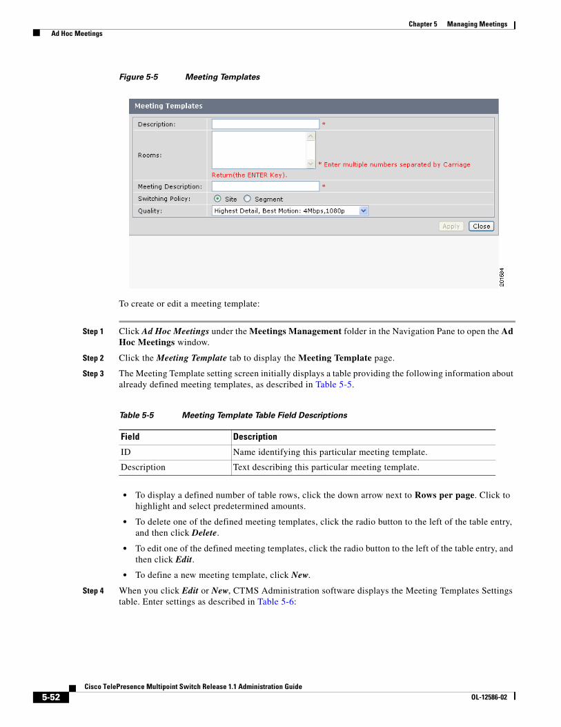
5-52Cisco TelePresence Multipoint Switch Release 1.1 Administration Guide
OL-12586-02
Chapter 5 Managing Meetings Ad Hoc Meetings
Figure 5-5 Meeting Templates
To create or edit a meeting template:
Step 1 Click Ad Hoc Meetings under the Meetings Management folder in the Navigation Pane to open the Ad Hoc Meetings window.
Step 2 Click the Meeting Template tab to display the Meeting Template page.
Step 3 The Meeting Template setting screen initially displays a table providing the following information about already defined meeting templates, as described in Table 5-5.
• To display a defined number of table rows, click the down arrow next to Rows per page. Click to highlight and select predetermined amounts.
• To delete one of the defined meeting templates, click the radio button to the left of the table entry, and then click Delete.
• To edit one of the defined meeting templates, click the radio button to the left of the table entry, and then click Edit.
• To define a new meeting template, click New.
Step 4 When you click Edit or New, CTMS Administration software displays the Meeting Templates Settings table. Enter settings as described in Table 5-6:
Table 5-5 Meeting Template Table Field Descriptions
Field Description
ID Name identifying this particular meeting template.
Description Text describing this particular meeting template.
5-53Cisco TelePresence Multipoint Switch Release 1.1 Administration Guide
OL-12586-02
Chapter 5 Managing Meetings Ad Hoc Meetings
• To register new or modified settings, click Apply.
• To restore the original settings, click Reset.
Table 5-6 Meeting Templates Settings
Field Description
Description Name identifying this particular meeting template. This name appears in the drop-down list of defined meeting templates. The maximum number of characters for this field is 62 characters
Rooms Defines the meeting room number of the CTMS end points invited to attend this ad hoc meeting. When entering multiple meeting room numbers, separate each room number with a carriage return by pressing “enter.”
Meeting Description Text describing this particular meeting template. The maximum number of characters for this field is 62 characters
Switching Policy Defines how CTMS calls are displayed during a meeting. CTMS displays active speakers on screen. There are two active speaker display options:
• Segment: (Speaker) With segment switching, each individual table segment (defined as a display and a camera) is displayed on the screen as that segment becomes the active speaker.
• Site: (Room) When you select “site,” all table segments for a particular room are displayed on screen when any segment in that room is the active speaker.
Click the appropriate radio button to select.
Note If you are running CTS 1.3 or later, you can control how Cisco TelePresence calls are displayed from the Cisco TelePresence phone interface. Press the Speaker softkey to display the active segment; press the Room softkey to display all segements from a particular site.
Quality This field sets the system bandwidth and screen resolution. A higher bandwidth increases video quality, but may also cause packets to be dropped and video to be interrupted. Choices:
• Highest Detail, Best Motion: 4Mbps 1080p
• Highest Detail, Better Motion: 3.5Mbps, 1080p
• Highest Detail, Good Motion: 3Mbps, 1080p
• High Detail, Best Motion: 3Mbps, 720p
• High Detail, Better Motion: 2Mbps, 720p
• High Detail, Good Motion: 1Mbps, 720p
Default is Highest Detail, Best Motion: 4Mbps 1080p.
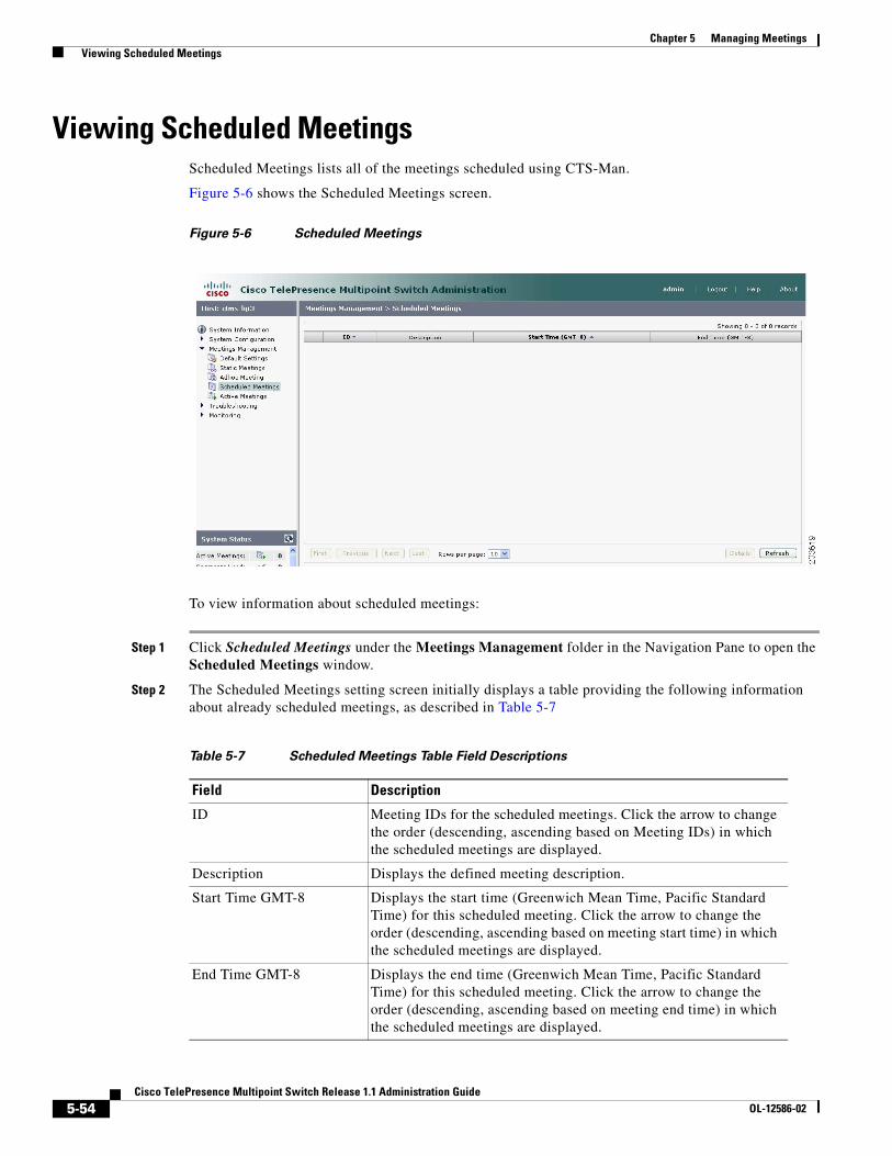
5-54Cisco TelePresence Multipoint Switch Release 1.1 Administration Guide
OL-12586-02
Chapter 5 Managing Meetings Viewing Scheduled Meetings
Viewing Scheduled MeetingsScheduled Meetings lists all of the meetings scheduled using CTS-Man.
Figure 5-6 shows the Scheduled Meetings screen.
Figure 5-6 Scheduled Meetings
To view information about scheduled meetings:
Step 1 Click Scheduled Meetings under the Meetings Management folder in the Navigation Pane to open the Scheduled Meetings window.
Step 2 The Scheduled Meetings setting screen initially displays a table providing the following information about already scheduled meetings, as described in Table 5-7
Table 5-7 Scheduled Meetings Table Field Descriptions
Field Description
ID Meeting IDs for the scheduled meetings. Click the arrow to change the order (descending, ascending based on Meeting IDs) in which the scheduled meetings are displayed.
Description Displays the defined meeting description.
Start Time GMT-8 Displays the start time (Greenwich Mean Time, Pacific Standard Time) for this scheduled meeting. Click the arrow to change the order (descending, ascending based on meeting start time) in which the scheduled meetings are displayed.
End Time GMT-8 Displays the end time (Greenwich Mean Time, Pacific Standard Time) for this scheduled meeting. Click the arrow to change the order (descending, ascending based on meeting end time) in which the scheduled meetings are displayed.
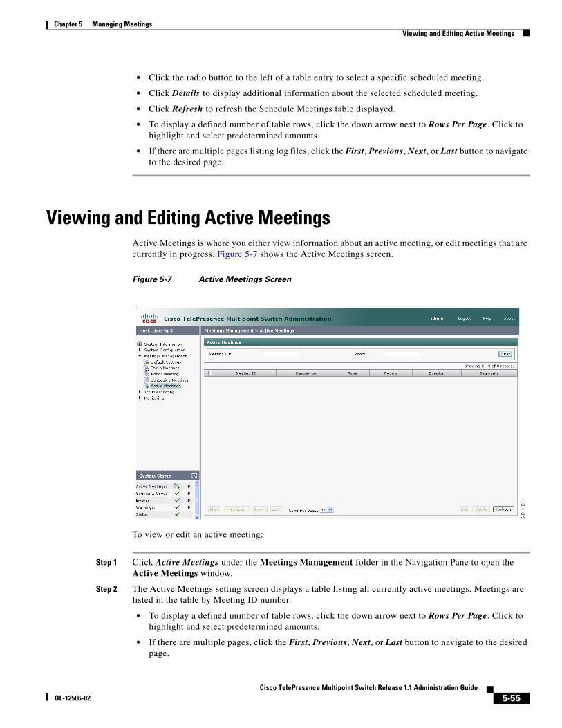
5-55Cisco TelePresence Multipoint Switch Release 1.1 Administration Guide
OL-12586-02
Chapter 5 Managing Meetings Viewing and Editing Active Meetings
• Click the radio button to the left of a table entry to select a specific scheduled meeting.
• Click Details to display additional information about the selected scheduled meeting.
• Click Refresh to refresh the Schedule Meetings table displayed.
• To display a defined number of table rows, click the down arrow next to Rows Per Page. Click to highlight and select predetermined amounts.
• If there are multiple pages listing log files, click the First, Previous, Next, or Last button to navigate to the desired page.
Viewing and Editing Active MeetingsActive Meetings is where you either view information about an active meeting, or edit meetings that are currently in progress. Figure 5-7 shows the Active Meetings screen.
Figure 5-7 Active Meetings Screen
To view or edit an active meeting:
Step 1 Click Active Meetings under the Meetings Management folder in the Navigation Pane to open the Active Meetings window.
Step 2 The Active Meetings setting screen displays a table listing all currently active meetings. Meetings are listed in the table by Meeting ID number.
• To display a defined number of table rows, click the down arrow next to Rows Per Page. Click to highlight and select predetermined amounts.
• If there are multiple pages, click the First, Previous, Next, or Last button to navigate to the desired page.
5-56Cisco TelePresence Multipoint Switch Release 1.1 Administration Guide
OL-12586-02
Chapter 5 Managing Meetings Viewing and Editing Active Meetings
• Click Refresh to refresh the Active Meetings table displayed.
Step 3 To use the filter at the top of the table to find a particular meeting, enter either the Meeting ID number or the Meeting Room number in the appropriate field and then click Filter.
Step 4 Click the radio button to the left of a table entry to select a particular meeting. Click Edit to display the Active Meetings setting table. Active Meeting management tasks (and information about active meetings) are described in Table 5-8
Table 5-8 Active Meetings Settings
Field Description
Meeting ID Displays the Meeting ID Number of the meeting selected. To delete this meeting (in other words, end this meeting), click the Delete Meeting radio button. Click Apply to end the meeting.
Meeting Description Displays the defined description for this meeting.
Meeting Type Displays the defined meeting type. Meeting types are static and ad hoc.
Room1, Room2... Lists the CTS end points (meeting rooms) attending this meeting. To delete a particular CTS end point, click the Delete Room radio button for that particular room. Click Apply to remove that room from the meeting.
Note For interoperability meetings, the CUVC connection is shown as one room in the Maximum Rooms setting.
Add Room(s) Defines additional meeting room numbers (CTMS end points) to attend this meeting. When entering multiple meeting room numbers, separate each room number with a carriage return by pressing “Enter.”
Note An interoperability connection cannot be dynamically added to a conference. It must be configured in the Static Meeting definition.
5-57Cisco TelePresence Multipoint Switch Release 1.1 Administration Guide
OL-12586-02
Chapter 5 Managing Meetings Viewing and Editing Active Meetings
Switching Policy Defines how CTMS calls are displayed during a meeting. CTMS displays active speakers on screen. There are two active speaker display options:
• Segment: (Speaker) With segment switching, each individual table segment (defined as a display and a camera) is displayed on the screen as that segment becomes the active speaker.
• Site: (Room) When you select “site,” all table segments for a particular room are displayed on screen when any segment in that room is the active speaker.
Click the appropriate radio button to select.
Note If you are running CTS 1.3 or later, you can control how Cisco TelePresence calls are displayed from the Cisco TelePresence phone interface. Press the Speaker softkey to display the active segment; press the Room softkey to display all segements from a particular site.
Video Announce When selected, if a new attendee joins the meeting, the attendee is displayed on-screen for 2 seconds. Options are Yes and No. Click the appropriate radio button to select.
Quality This field sets the system bandwidth and screen resolution. A higher bandwidth increases video quality, but may also cause packets to be dropped and video to be interrupted. Choices:
• Highest Detail, Best Motion: 4Mbps 1080p
• Highest Detail, Better Motion: 3.5Mbps, 1080p
• Highest Detail, Good Motion: 3Mbps, 1080p
• High Detail, Best Motion: 3Mbps, 720p
• High Detail, Better Motion: 2Mbps, 720p
• High Detail, Good Motion: 1Mbps, 720p
Default is Highest Detail, Best Motion: 4Mbps 1080p.
VIP Mode When selected, one endpoint is defined as the “VIP.” A VIP is broadcast to all other meeting attendees for the entire meeting. The VIP’s endpoint continues to switch between endpoints with active speakers. Only one VIP can be defined per meeting.
Options are “Yes” and “No.” Click the appropriate radio button to select.
Lock Locking the meeting means that no settings can be changed for this meeting. Options are Yes and No. Click the appropriate radio button to select.
Table 5-8 Active Meetings Settings
Field Description
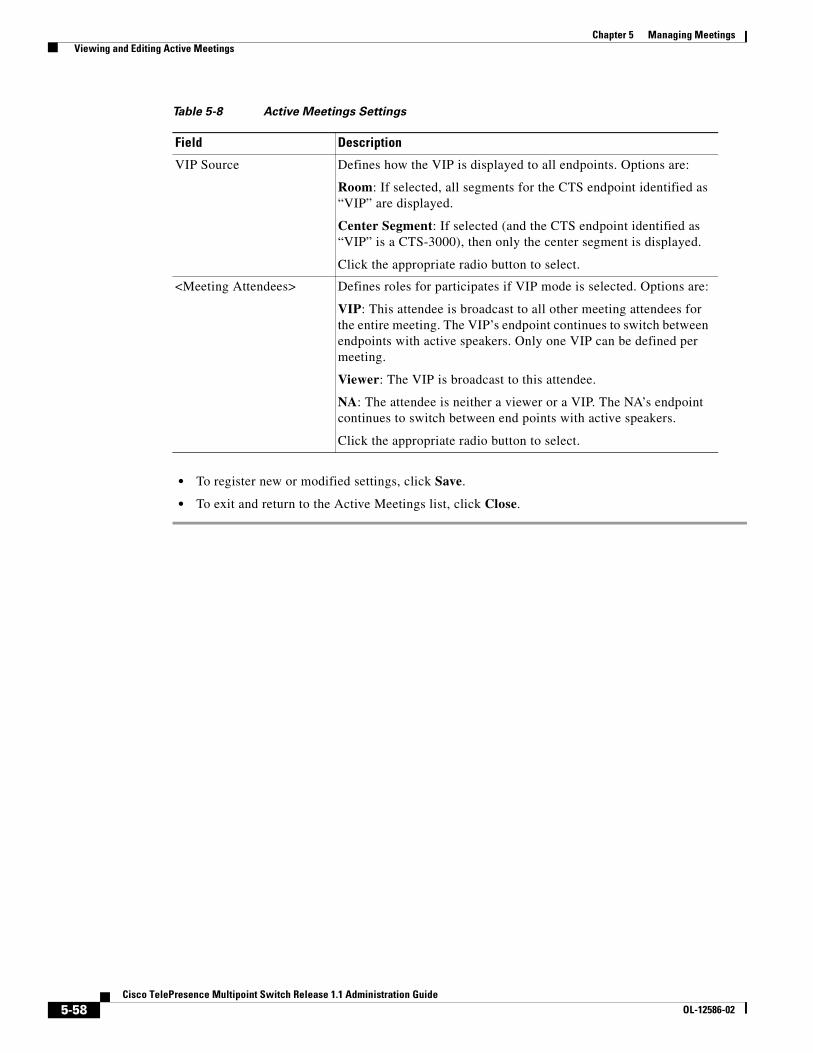
5-58Cisco TelePresence Multipoint Switch Release 1.1 Administration Guide
OL-12586-02
Chapter 5 Managing Meetings Viewing and Editing Active Meetings
• To register new or modified settings, click Save.
• To exit and return to the Active Meetings list, click Close.
VIP Source Defines how the VIP is displayed to all endpoints. Options are:
Room: If selected, all segments for the CTS endpoint identified as “VIP” are displayed.
Center Segment: If selected (and the CTS endpoint identified as “VIP” is a CTS-3000), then only the center segment is displayed.
Click the appropriate radio button to select.
<Meeting Attendees> Defines roles for participates if VIP mode is selected. Options are:
VIP: This attendee is broadcast to all other meeting attendees for the entire meeting. The VIP’s endpoint continues to switch between endpoints with active speakers. Only one VIP can be defined per meeting.
Viewer: The VIP is broadcast to this attendee.
NA: The attendee is neither a viewer or a VIP. The NA’s endpoint continues to switch between end points with active speakers.
Click the appropriate radio button to select.
Table 5-8 Active Meetings Settings
Field Description
C H A P T E R
6-59Cisco TelePresence Multipoint Switch Release 1.1 Administration Guide
OL-12586-02
6Troubleshooting the CTMS System
Initial Release: May 5, 2008, OL-12586-02Last Revised: August 4, 2008
Contents• Overview, page 6-59
• Viewing CTMS Alarms and System Error Messages, page 6-60
• Configuring the Severity Level of System Error Messages, page 6-62
• Filtering the Log File Table Listings, page 6-63
• Downloading Log Files, page 6-64
• Troubleshooting Specific Issues, page 6-64
OverviewThe Troubleshooting folder contains tools that enable you to do the following:
• View the latest CTMS alarms and system error messages
• Configure the severity level of system level error messages and alarms for specific process areas
• Filter the Log File table listings.
Figure 6-1 shows the main Troubleshooting window,
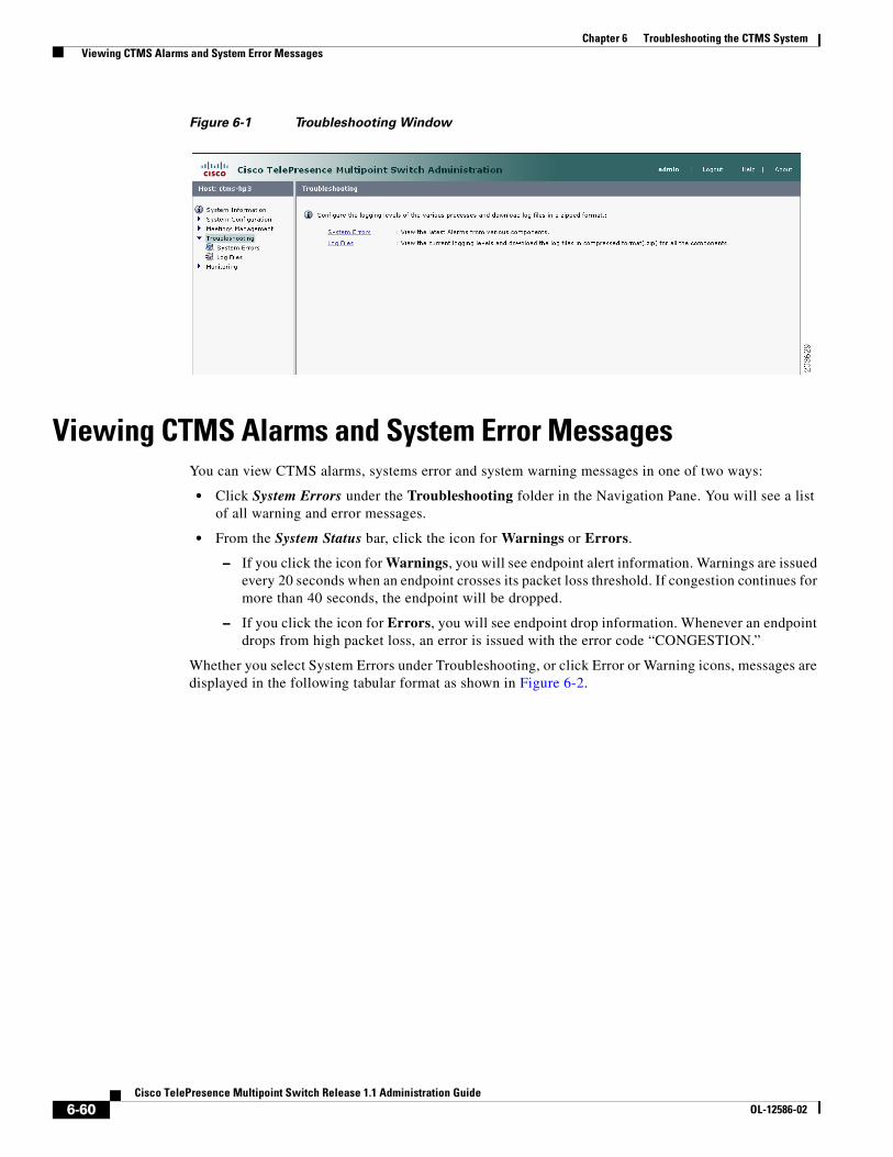
6-60Cisco TelePresence Multipoint Switch Release 1.1 Administration Guide
OL-12586-02
Chapter 6 Troubleshooting the CTMS System Viewing CTMS Alarms and System Error Messages
Figure 6-1 Troubleshooting Window
Viewing CTMS Alarms and System Error MessagesYou can view CTMS alarms, systems error and system warning messages in one of two ways:
• Click System Errors under the Troubleshooting folder in the Navigation Pane. You will see a list of all warning and error messages.
• From the System Status bar, click the icon for Warnings or Errors.
– If you click the icon for Warnings, you will see endpoint alert information. Warnings are issued every 20 seconds when an endpoint crosses its packet loss threshold. If congestion continues for more than 40 seconds, the endpoint will be dropped.
– If you click the icon for Errors, you will see endpoint drop information. Whenever an endpoint drops from high packet loss, an error is issued with the error code “CONGESTION.”
Whether you select System Errors under Troubleshooting, or click Error or Warning icons, messages are displayed in the following tabular format as shown in Figure 6-2.
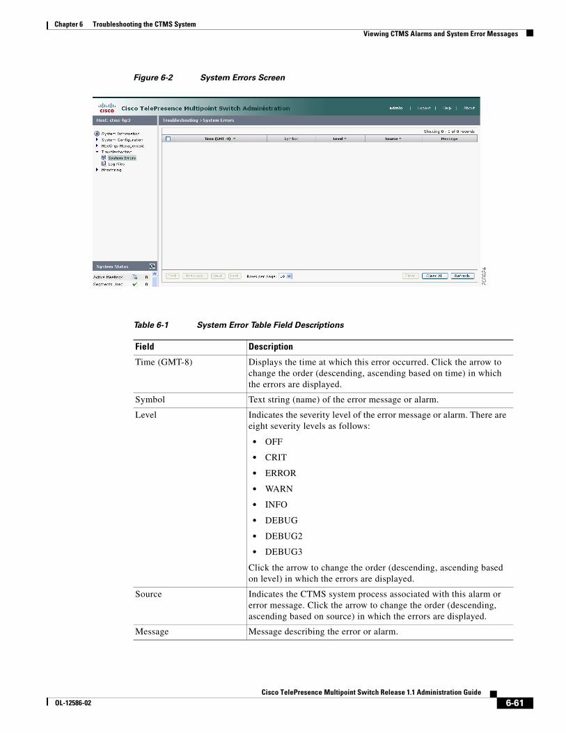
6-61Cisco TelePresence Multipoint Switch Release 1.1 Administration Guide
OL-12586-02
Chapter 6 Troubleshooting the CTMS System Viewing CTMS Alarms and System Error Messages
Figure 6-2 System Errors Screen
Table 6-1 System Error Table Field Descriptions
Field Description
Time (GMT-8) Displays the time at which this error occurred. Click the arrow to change the order (descending, ascending based on time) in which the errors are displayed.
Symbol Text string (name) of the error message or alarm.
Level Indicates the severity level of the error message or alarm. There are eight severity levels as follows:
• OFF
• CRIT
• ERROR
• WARN
• INFO
• DEBUG
• DEBUG2
• DEBUG3
Click the arrow to change the order (descending, ascending based on level) in which the errors are displayed.
Source Indicates the CTMS system process associated with this alarm or error message. Click the arrow to change the order (descending, ascending based on source) in which the errors are displayed.
Message Message describing the error or alarm.
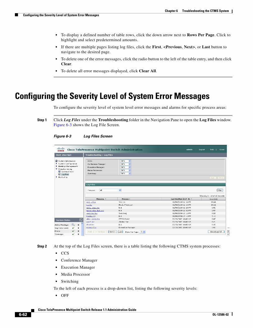
6-62Cisco TelePresence Multipoint Switch Release 1.1 Administration Guide
OL-12586-02
Chapter 6 Troubleshooting the CTMS System Configuring the Severity Level of System Error Messages
• To display a defined number of table rows, click the down arrow next to Rows Per Page. Click to highlight and select predetermined amounts.
• If there are multiple pages listing log files, click the First, <Previous, Next>, or Last button to navigate to the desired page.
• To delete one of the error messages, click the radio button to the left of the table entry, and then click Clear.
• To delete all error messages displayed, click Clear All.
Configuring the Severity Level of System Error MessagesTo configure the severity level of system level error messages and alarms for specific process areas:
Step 1 Click Log Files under the Troubleshooting folder in the Navigation Pane to open the Log Files window. Figure 6-3 shows the Log File Screen.
Figure 6-3 Log Files Screen
Step 2 At the top of the Log Files screen, there is a table listing the following CTMS system processes:
• CCS
• Conference Manager
• Execution Manager
• Media Processor
• Switching
To the left of each process is a drop-down list, listing the following severity levels:
• OFF
6-63Cisco TelePresence Multipoint Switch Release 1.1 Administration Guide
OL-12586-02
Chapter 6 Troubleshooting the CTMS System Filtering the Log File Table Listings
• CRIT
• ERROR
• WARN
• INFO
• DEBUG
• DEBUG2
• DEBUG3
Click the down arrow to display the drop-down list of defined levels of severity, and then click to highlight and select a specific severity level for all error messages and alarms associated a particular CTMS system process.
Note Log levels create varying amounts of data; for example, DEBUG creates more log entries than CRIT. Because verbose logs can impact system performance, use verbose logs only to track a problem.
Filtering the Log File Table ListingsTo filter the log files displayed in the Log File Table:
Step 1 Click Log Files under the Troubleshooting folder in the Navigation Pane to open the Log Files window.
Step 2 At the middle of the Log Files screen, click the down arrow to the right of Processes to display a list of CTMS process areas, then click to highlight and select a specific process area on which to filter log files. Choices are:
• All
• CCS
• Conference Manager
• Execution Manager
• Media Processor
• Switching
• SIP
• Web-UI
• CDR Logs
• Core
• Alarm Logs
Step 3 Click the Filter button to display the logs files associated with the selected process area in the Log Files table.
6-64Cisco TelePresence Multipoint Switch Release 1.1 Administration Guide
OL-12586-02
Chapter 6 Troubleshooting the CTMS System Downloading Log Files
Downloading Log FilesTo download log files from the Log File table:
Step 1 Click Log Files under the Troubleshooting folder in the Navigation Pane to open the Log Files window.
Step 2 At the bottom of the Log Files screen is the Log File table, which lists the available log files. The table is organized as follows:
Step 3 To display a defined number of table rows, click the down arrow next to Rows per Page. Click to highlight and select predetermined amounts. If there are multiple pages listing log files, click the First, Previous, Next, or Last button to navigate to the desired page.
Step 4 Click the filename of a log file to download that file. Click the Download All button to download all log files listed.
Troubleshooting Specific IssuesTable 6-3 describes some specific problems and possible solutions.
Table 6-2 Log Table Field Descriptions
Field Description
Filename Filename of the log file. Click the arrow to change the order (descending, ascending based on alphabetical order of the filenames) in which the log files are displayed.
Process CTMS system process area. Click the arrow to change the order (descending, ascending based on alphabetical order of the processes) in which the log files are displayed.
Last Modified (GMT-8) Time (Greenwich Mean Time, Pacific Standard Time) at which the log file was collected. Click the arrow to change the order (descending, ascending based on time) in which the log files are displayed.
Size Size (in kilobytes) of the compressed log file.
6-65Cisco TelePresence Multipoint Switch Release 1.1 Administration Guide
OL-12586-02
Chapter 6 Troubleshooting the CTMS System Troubleshooting Specific Issues
Table 6-3 Specific Problems and Possible Solutions
Problem Possible Solutions
Unable to connect to static meetings or to initiate ad hoc meetings
1. Verify network connectivity.
2. Verify IP address of the CTMS configured on Unified CM SIP trunk.
Unable to connect to static meetings but able to connect to ad hoc meetings
1. Verify the that static number being dialed is a valid number.
2. Verify that SIP Trunk security profile “Outbound transport type” is set to “UDP.”
3. Verify that all Unified CM servers are entered in Unified CM settings.
Unable to connect to ad hoc meetings but able to connect to static meetings
1. Verify that the CTS endpoints numbers are entered correctly.
2. Verify that rooms are available.
Scheduled meetings don’t connect 1. Check the registration status of the CTMS on the CTM page.
2. Verify that the scheduled meeting is listed on the CTMS (under Scheduled Meetings).
Cisco TelePresence Interoperability: Unified CM sends an error message of “Service not available” to CTMS when CTMS tries to establish call to CUVC.
1. Check to see if there are sufficient ports. Unified CM delivers a “Service not available” message when CTMS places a call to CUVC and there are an insufficient number of ports available.
2. Verify the number dialed for the CUVC connection is defined to Unified CM as a SIP trunk, and is correctly configured.

6-66Cisco TelePresence Multipoint Switch Release 1.1 Administration Guide
OL-12586-02
Chapter 6 Troubleshooting the CTMS System Troubleshooting Specific Issues
C H A P T E R
7-67Cisco TelePresence Multipoint Switch Release 1.1 Administration Guide
OL-12586-02
7Monitoring CTMS System Processes
Initial Release: May 5, 2008, OL-12586-02Last Revised: August 4, 2008
Contents• Overview, page 7-67
• Monitoring System Status, page 7-68
• Monitoring and Restarting System Processes, page 7-69
• Viewing Call Statistics, page 7-70
• Room Testing, page 7-72
OverviewThe Monitor folder contains tools that enable you to monitor the overall CTMS system state and the running state of individual processes. Figure 7-1 shows the initial Monitoring window.
Figure 7-1 Monitoring Window
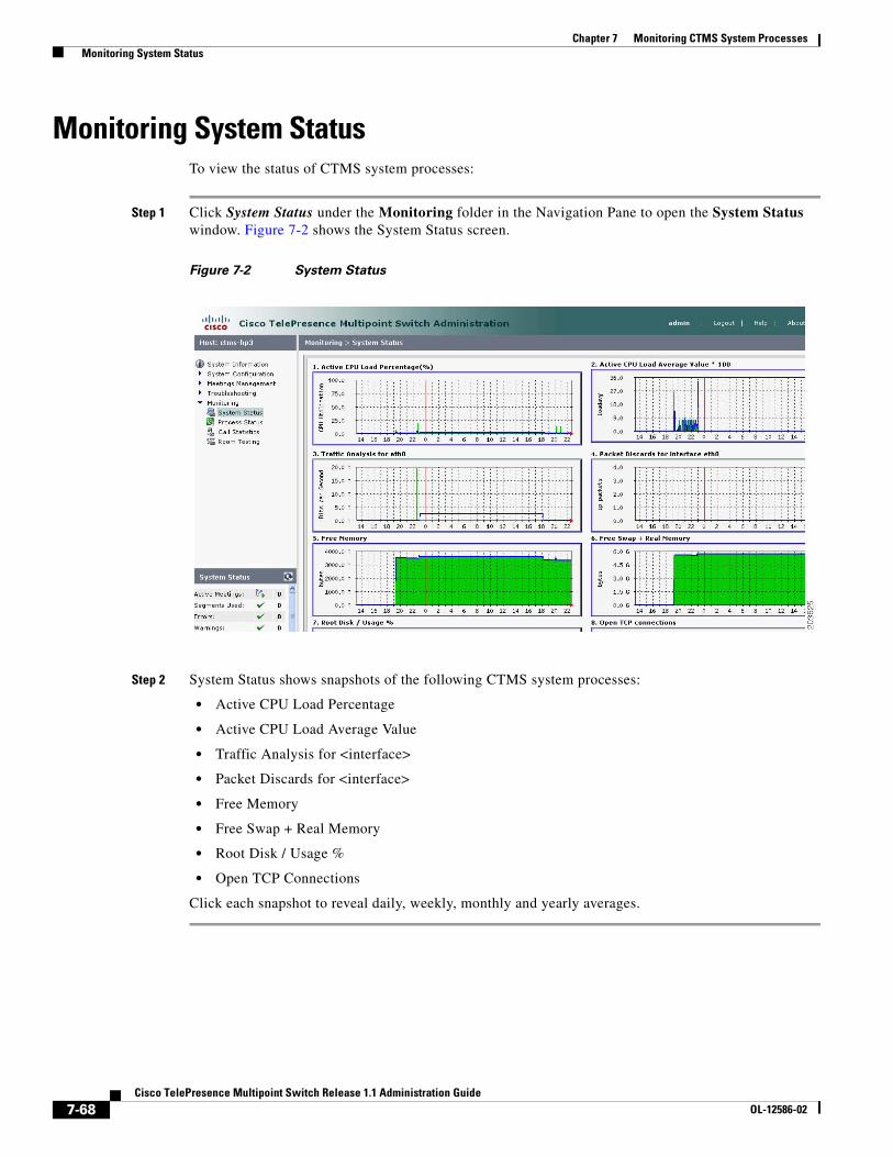
7-68Cisco TelePresence Multipoint Switch Release 1.1 Administration Guide
OL-12586-02
Chapter 7 Monitoring CTMS System Processes Monitoring System Status
Monitoring System StatusTo view the status of CTMS system processes:
Step 1 Click System Status under the Monitoring folder in the Navigation Pane to open the System Status window. Figure 7-2 shows the System Status screen.
Figure 7-2 System Status
Step 2 System Status shows snapshots of the following CTMS system processes:
• Active CPU Load Percentage
• Active CPU Load Average Value
• Traffic Analysis for <interface>
• Packet Discards for <interface>
• Free Memory
• Free Swap + Real Memory
• Root Disk / Usage %
• Open TCP Connections
Click each snapshot to reveal daily, weekly, monthly and yearly averages.
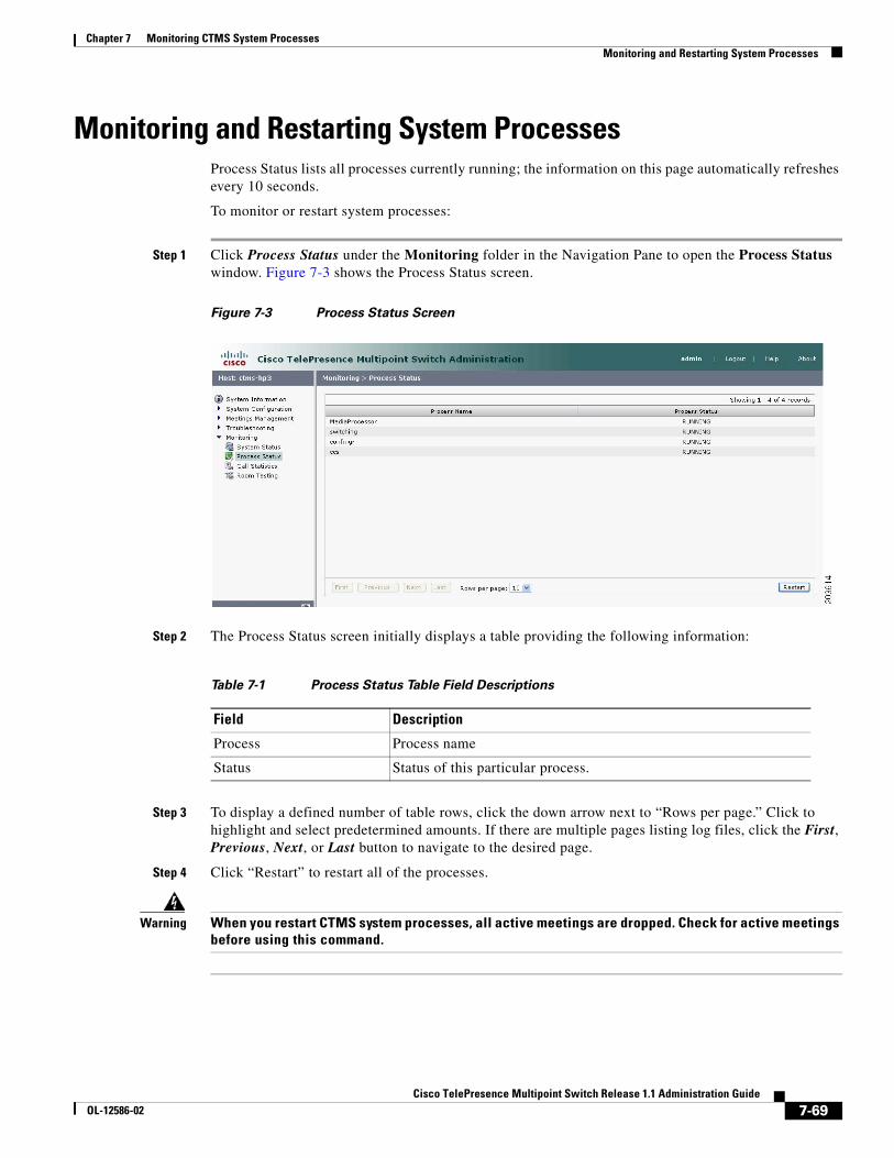
7-69Cisco TelePresence Multipoint Switch Release 1.1 Administration Guide
OL-12586-02
Chapter 7 Monitoring CTMS System Processes Monitoring and Restarting System Processes
Monitoring and Restarting System ProcessesProcess Status lists all processes currently running; the information on this page automatically refreshes every 10 seconds.
To monitor or restart system processes:
Step 1 Click Process Status under the Monitoring folder in the Navigation Pane to open the Process Status window. Figure 7-3 shows the Process Status screen.
Figure 7-3 Process Status Screen
Step 2 The Process Status screen initially displays a table providing the following information:
Step 3 To display a defined number of table rows, click the down arrow next to “Rows per page.” Click to highlight and select predetermined amounts. If there are multiple pages listing log files, click the First, Previous, Next, or Last button to navigate to the desired page.
Step 4 Click “Restart” to restart all of the processes.
Warning When you restart CTMS system processes, all active meetings are dropped. Check for active meetings before using this command.
Table 7-1 Process Status Table Field Descriptions
Field Description
Process Process name
Status Status of this particular process.
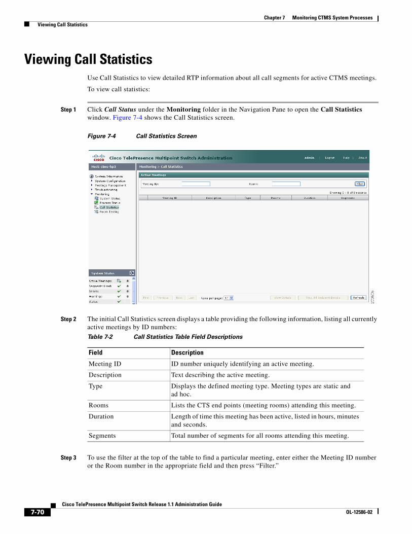
7-70Cisco TelePresence Multipoint Switch Release 1.1 Administration Guide
OL-12586-02
Chapter 7 Monitoring CTMS System Processes Viewing Call Statistics
Viewing Call StatisticsUse Call Statistics to view detailed RTP information about all call segments for active CTMS meetings.
To view call statistics:
Step 1 Click Call Status under the Monitoring folder in the Navigation Pane to open the Call Statistics window. Figure 7-4 shows the Call Statistics screen.
Figure 7-4 Call Statistics Screen
Step 2 The initial Call Statistics screen displays a table providing the following information, listing all currently active meetings by ID numbers:
Step 3 To use the filter at the top of the table to find a particular meeting, enter either the Meeting ID number or the Room number in the appropriate field and then press “Filter.”
Table 7-2 Call Statistics Table Field Descriptions
Field Description
Meeting ID ID number uniquely identifying an active meeting.
Description Text describing the active meeting.
Type Displays the defined meeting type. Meeting types are static and ad hoc.
Rooms Lists the CTS end points (meeting rooms) attending this meeting.
Duration Length of time this meeting has been active, listed in hours, minutes and seconds.
Segments Total number of segments for all rooms attending this meeting.
7-71Cisco TelePresence Multipoint Switch Release 1.1 Administration Guide
OL-12586-02
Chapter 7 Monitoring CTMS System Processes Viewing Call Statistics
Step 4 To display a defined number of table rows, click the down arrow next to “Rows per page.” Click to highlight and select predetermined amounts. If there are multiple pages, click the First, Previous, Next, or Last button to navigate to the desired page.
Step 5 Click Refresh to refresh the active meetings displayed.
Step 6 Click the radio button to the left of a table entry to select a particular meeting. Click View Details to display an abbreviated view of RTP statistics for the selected meeting. To see all RTP call statistics details for a particular meeting, click Details from the abbreviated view.
Step 7 Click View All Endpoint Details to display a subset of audio and video RTP statistics for all active meetings. To see all RTP call statistics details for all meeting, click Details from the abbreviated view.
Complete RTP statistic details include the following information for each CTMS call segment:
Audio Statistics
• SSRC (Receive)
• SSRC (Transmit)
• Max Jitter (Period)
• Max Jitter (Call)
• Mean Jitter (Period)
• Mean Jitter (Call)
• Jitter Standard Deviation (Period)
• Jitter Standard Deviation (Call)
• Jitter Spike (Period)
• Jitter Spike (Call)
• Jitter Spike Rate % (Period)
• Jitter Spike Rate % (Call)
• Total Packets (Receive)
• Total Packets (Transmit)
• Lost Packet Rate % (Receive)
• Lost Packet Rate (Transmit)
• Duplicate Packets
• Out of Order Packets
• Total Switching (Call)
• Max Switching (Period)
Video Statistics
• SSRC (Receive)
• SSRC (Transmit)
• Max Jitter (Period)
• Max Jitter (Call)
• Mean Jitter (Period)
• Mean Jitter (Call)
7-72Cisco TelePresence Multipoint Switch Release 1.1 Administration Guide
OL-12586-02
Chapter 7 Monitoring CTMS System Processes Room Testing
• Jitter Standard Deviation (Period)
• Jitter Standard Deviation (Call)
• Jitter Spike (Period)
• Jitter Spike (Call)
• Jitter Spike Rate % (Period)
• Jitter Spike Rate % (Call)
• Total Packets (Receive)
• Total Packets (Transmit)
• Lost Packet Rate % (Receive)
• Lost Packet Rate (Transmit)
• Duplicate Packets
• Out of Order Packets
• Total Switching (Call)
• Max Switching (Period)
• Feedback Packets Dropped
• Total NAKs
• Max Frame Window (Period)
• Max Frame Window (Call)
• Frame Window Spikes (Period)
• Frame Window Spikes (Call)
• Frame Window Spike Rate % (Period)
• Frame Window Spike Rate % (Call)
• IDR Packets (Received)
• IDR Packets (Transmit)
Room TestingUse Room Testing to perform loopback or force switch testing.
To perform loopback or force switch testing:
Step 1 Click Room Testing under the Monitoring folder in the Navigation Pane to open the Room Testing window. Figure 7-5 shows the Room Testing screen.
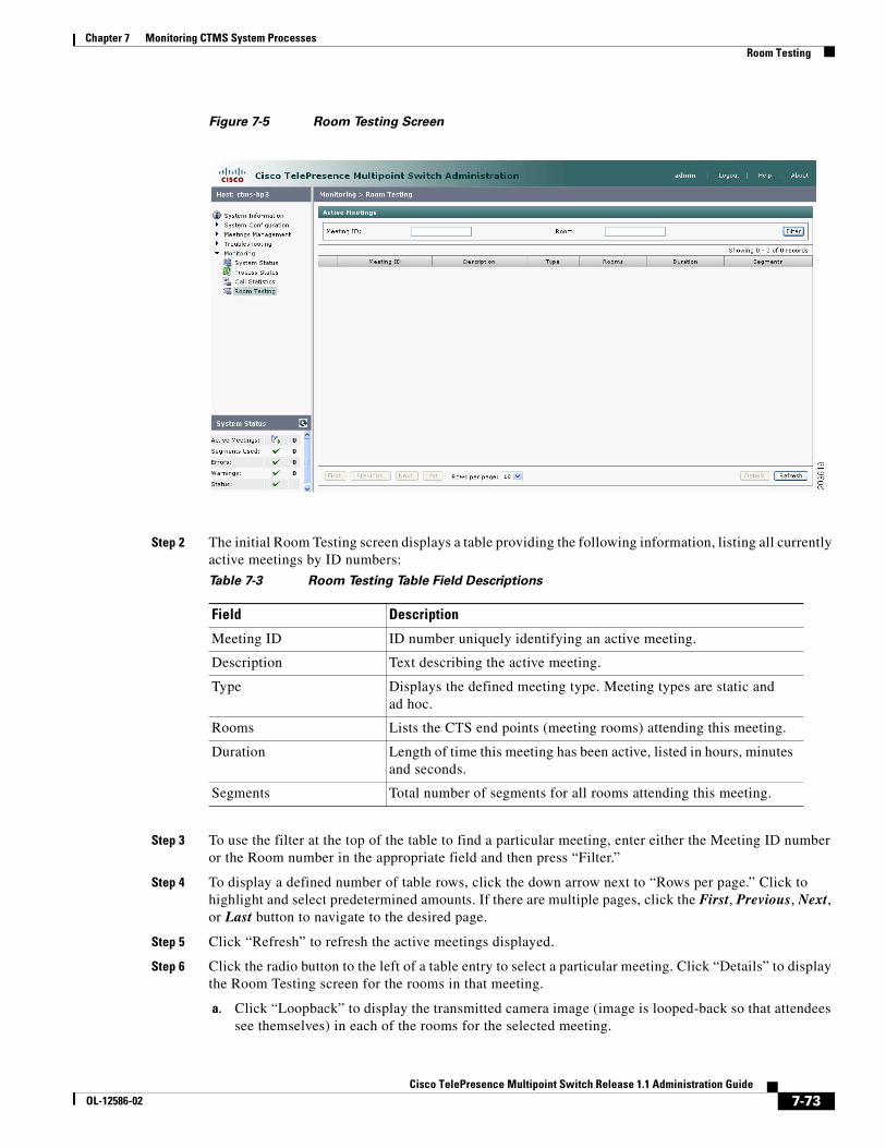
7-73Cisco TelePresence Multipoint Switch Release 1.1 Administration Guide
OL-12586-02
Chapter 7 Monitoring CTMS System Processes Room Testing
Figure 7-5 Room Testing Screen
Step 2 The initial Room Testing screen displays a table providing the following information, listing all currently active meetings by ID numbers:
Step 3 To use the filter at the top of the table to find a particular meeting, enter either the Meeting ID number or the Room number in the appropriate field and then press “Filter.”
Step 4 To display a defined number of table rows, click the down arrow next to “Rows per page.” Click to highlight and select predetermined amounts. If there are multiple pages, click the First, Previous, Next, or Last button to navigate to the desired page.
Step 5 Click “Refresh” to refresh the active meetings displayed.
Step 6 Click the radio button to the left of a table entry to select a particular meeting. Click “Details” to display the Room Testing screen for the rooms in that meeting.
a. Click “Loopback” to display the transmitted camera image (image is looped-back so that attendees see themselves) in each of the rooms for the selected meeting.
Table 7-3 Room Testing Table Field Descriptions
Field Description
Meeting ID ID number uniquely identifying an active meeting.
Description Text describing the active meeting.
Type Displays the defined meeting type. Meeting types are static and ad hoc.
Rooms Lists the CTS end points (meeting rooms) attending this meeting.
Duration Length of time this meeting has been active, listed in hours, minutes and seconds.
Segments Total number of segments for all rooms attending this meeting.

7-74Cisco TelePresence Multipoint Switch Release 1.1 Administration Guide
OL-12586-02
Chapter 7 Monitoring CTMS System Processes Room Testing
b. Click “Force Switch” to force site switching between all of the rooms in the selected meeting.
c. Click “Close” to return to the Room Testing active meeting listing screen.
C H A P T E R
8-75Cisco TelePresence Multipoint Switch Release 1.1 Administration Guide
OL-12586-02
8Interoperability with Legacy Video Conferencing Devices
Initial Release: May 5, 2008, OL-12586-02Last Revised: August 4, 2008
Contents• Overview, page 8-75
– How Cisco TelePresence Interoperability Works, page 8-75
– Benefits, page 8-77
– Caveats, page 8-77
• Prerequisites, page 8-78
• Configuring Cisco TelePresence Interoperability, page 8-79
– Configuring Unified CM for Cisco TelePresence Interoperability, page 8-79
– Configuring CUVC for Cisco TelePresence Interoperability, page 8-81
– Configuring CTMS for Cisco TelePresence Interoperability, page 8-85
OverviewCisco TelePresence is based on open standards, including SIP, H.264 and G.711. With Cisco TelePresence System (CTS) Release 1.3 and CTMS Release 1.1, Cisco TelePresence now supports interoperability between Cisco TelePresence systems and standard definition video conferencing/video telephony using the Cisco Unified Video Conferencing 3500 series MCU (CUVC).
How Cisco TelePresence Interoperability WorksAs shown in Figure 8-1, CTS endpoints send a copy of their audio in G.711 format to the CTMS server. CTMS then determines which CTS segment is emitting the most dominant audio and requests that segment to send a copy of that segment’s video in Common Intermediate Format (CIF) resolution. CTMS
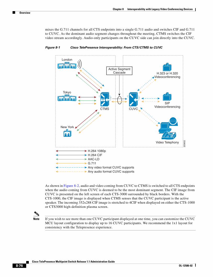
8-76Cisco TelePresence Multipoint Switch Release 1.1 Administration Guide
OL-12586-02
Chapter 8 Interoperability with Legacy Video Conferencing Devices Overview
mixes the G.711 channels for all CTS endpoints into a single G.711 audio and switches CIF and G.711 to CUVC. As the dominant audio segment changes throughout the meeting, CTMS switches the CIF video stream accordingly. Audio-only participants on the CUVC side can join directly into the CUVC.
Figure 8-1 Cisco TelePresence Interoperability: From CTS/CTMS to CUVC
As shown in Figure 8-2, audio and video coming from CUVC to CTMS is switched to all CTS endpoints when the audio coming from CUVC is deemed to be the most dominant segment. The CIF image from CUVC is presented on the left screen of each CTS-3000 surrounded by black borders. With the CTS-1000, the CIF image is displayed when CTMS senses that the CUVC participant is the active speaker. The incoming 352x288 CIF image is stretched to 4CIF when displayed on either the CTS-1000 or CTS3000 high-definition plasma screen.
Note If you wish to see more than one CUVC participant displayed at one time, you can customize the CUVC MCU layout configuration to display up to 16 CUVC participants. We recommend the 1x1 layout for consistency with the Telepresence experience.
IP
London
Tokyo
New York
CTMS
H.264 1080p
CUVC
H.323 or H.320Videoconferencing
SIPVideoconferencing
Video Telephony
H.264 CIFAAC-LDG.711Any video format CUVC supportsAny audio format CUVC supports
Active SegmentCascade
2036
52
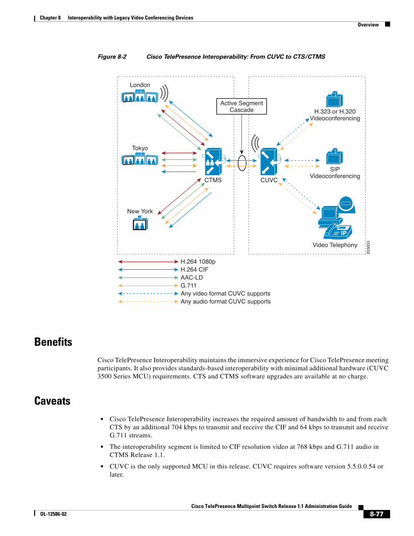
8-77Cisco TelePresence Multipoint Switch Release 1.1 Administration Guide
OL-12586-02
Chapter 8 Interoperability with Legacy Video Conferencing Devices Overview
Figure 8-2 Cisco TelePresence Interoperability: From CUVC to CTS/CTMS
BenefitsCisco TelePresence Interoperability maintains the immersive experience for Cisco TelePresence meeting participants. It also provides standards-based interoperability with minimal additional hardware (CUVC 3500 Series MCU) requirements. CTS and CTMS software upgrades are available at no charge.
Caveats• Cisco TelePresence Interoperability increases the required amount of bandwidth to and from each
CTS by an additional 704 kbps to transmit and receive the CIF and 64 kbps to transmit and receive G.711 streams.
• The interoperability segment is limited to CIF resolution video at 768 kbps and G.711 audio in CTMS Release 1.1.
• CUVC is the only supported MCU in this release. CUVC requires software version 5.5.0.0.54 or later.
IP
London
Tokyo
New York
CTMS
H.264 1080p
CUVC
H.323 or H.320Videoconferencing
SIPVideoconferencing
Video Telephony
H.264 CIFAAC-LDG.711Any video format CUVC supportsAny audio format CUVC supports
Active SegmentCascade
2036
53
8-78Cisco TelePresence Multipoint Switch Release 1.1 Administration Guide
OL-12586-02
Chapter 8 Interoperability with Legacy Video Conferencing Devices Prerequisites
• CUVC participants will not experience the spatial audio generated by CTS. CUVC participants hear all Cisco TelePresence participants mixed together in G.711.
• CUVC as an SCCP conference resource managed by Unified CM is not a supported option.The CUVC must be defined as a SIP trunk (and optionally an H.323 gateway) to Unified CM.
• CTS participants hear CUVC participants mixed together in G.711; audio will be heard from the same segment as that which is showing the CIF video.
• CTS and CUVC participants are not able to share slides or documents using H.239. Use another application for document sharing between CTS and CUVC, such as MeetingPlace or WebEx.
• Far End Camera Control (FECC) is not available to CTS participants during an interoperability call.
• Each interop conference uses one CTMS port and one CUVC port for each conference because each meeting utilizes a port for the cascade link. For example, CTMS normally can support 48 segments, and CUVC-3515-24 can support up to 24 participants. During interop meetings, CTMS supports a maximum of 47 segments and CUVC supports a maximum of 23 participants.
• Encryption is not supported for CTMS, Release 1.1, including interoperability calls.
PrerequisitesInteroperability between traditional video conferencing devices and CTS requires three components:
• CTMS
• Cisco Unified Communications Manager (Unified CM)
• CUVC MCU
The software and hardware requirements for Cisco TelePresence Interoperability are as follows:
CUVC Software and Hardware Requirements
• CUVC MCU Release 5.5.0.0.54:MP or later
• CUVC EMP Release 5.5.2.0.2:EMP or later
For additional information about configuring CUVC, refer to the Configuration Guide for the Cisco Unified Videoconferencing 3545 MCU Release 5.5.
Unified CM Software Requirements
• Unified CM Software Release 6.0 or later
For additional information about configuring Unified CM for Cisco TelePresence System, refer to the Cisco Unified Communications Manager Installation Guide for the Cisco TelePresence System.
For information about configuring Unified CM, refer to Cisco Unified Communications Manager Version 6.0 and Cisco Unified Communications Manager Version 6.1.
CTS Endpoint Software Requirements
• CTS Software Release 1.3 or later
For more information about CTS Administration Software, refer to the Cisco TelePresence System Release 1.3 Administrator’s Guide.
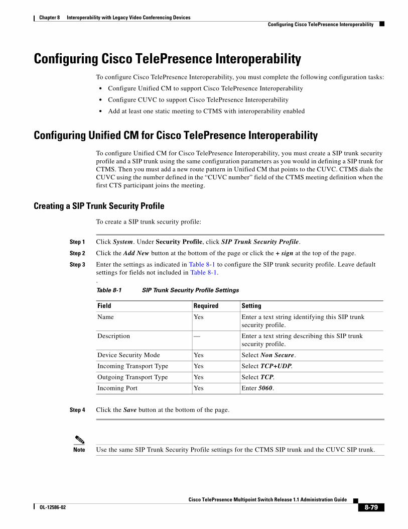
8-79Cisco TelePresence Multipoint Switch Release 1.1 Administration Guide
OL-12586-02
Chapter 8 Interoperability with Legacy Video Conferencing Devices Configuring Cisco TelePresence Interoperability
Configuring Cisco TelePresence InteroperabilityTo configure Cisco TelePresence Interoperability, you must complete the following configuration tasks:
• Configure Unified CM to support Cisco TelePresence Interoperability
• Configure CUVC to support Cisco TelePresence Interoperability
• Add at least one static meeting to CTMS with interoperability enabled
Configuring Unified CM for Cisco TelePresence InteroperabilityTo configure Unified CM for Cisco TelePresence Interoperability, you must create a SIP trunk security profile and a SIP trunk using the same configuration parameters as you would in defining a SIP trunk for CTMS. Then you must add a new route pattern in Unified CM that points to the CUVC. CTMS dials the CUVC using the number defined in the “CUVC number” field of the CTMS meeting definition when the first CTS participant joins the meeting.
Creating a SIP Trunk Security Profile
To create a SIP trunk security profile:
Step 1 Click System. Under Security Profile, click SIP Trunk Security Profile.
Step 2 Click the Add New button at the bottom of the page or click the + sign at the top of the page.
Step 3 Enter the settings as indicated in Table 8-1 to configure the SIP trunk security profile. Leave default settings for fields not included in Table 8-1..
Step 4 Click the Save button at the bottom of the page.
Note Use the same SIP Trunk Security Profile settings for the CTMS SIP trunk and the CUVC SIP trunk.
Table 8-1 SIP Trunk Security Profile Settings
Field Required Setting
Name Yes Enter a text string identifying this SIP trunk security profile.
Description — Enter a text string describing this SIP trunk security profile.
Device Security Mode Yes Select Non Secure.
Incoming Transport Type Yes Select TCP+UDP.
Outgoing Transport Type Yes Select TCP.
Incoming Port Yes Enter 5060.
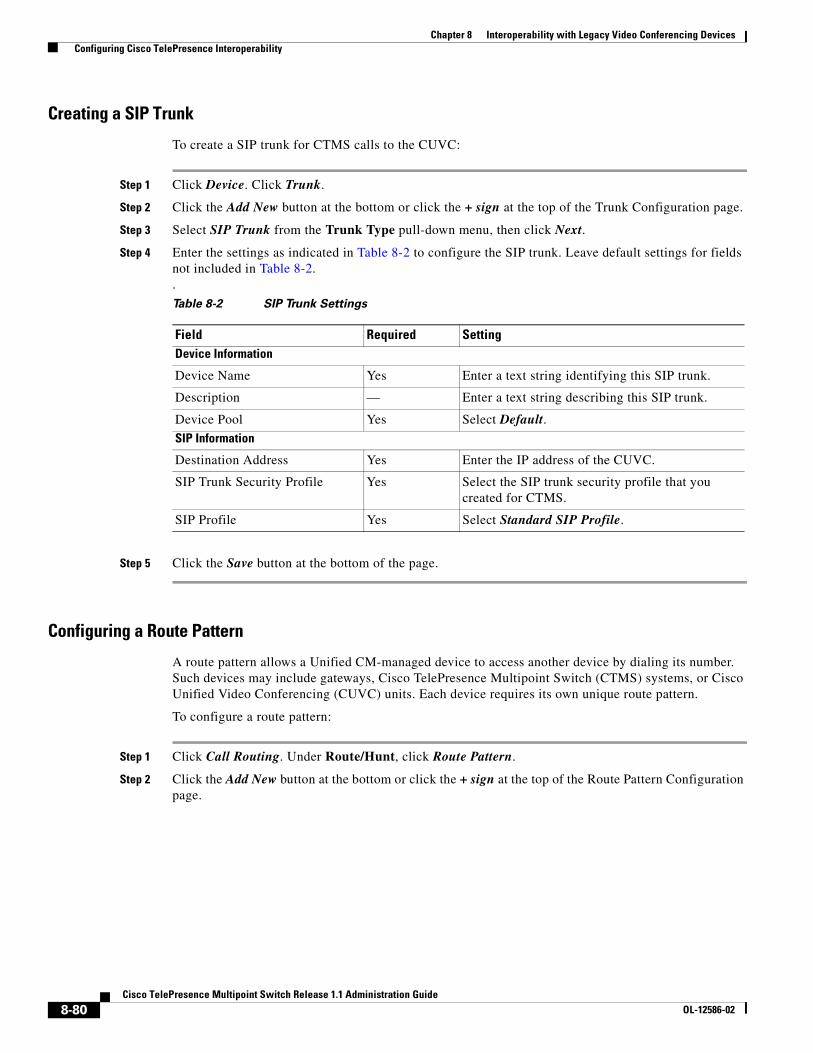
8-80Cisco TelePresence Multipoint Switch Release 1.1 Administration Guide
OL-12586-02
Chapter 8 Interoperability with Legacy Video Conferencing Devices Configuring Cisco TelePresence Interoperability
Creating a SIP Trunk
To create a SIP trunk for CTMS calls to the CUVC:
Step 1 Click Device. Click Trunk.
Step 2 Click the Add New button at the bottom or click the + sign at the top of the Trunk Configuration page.
Step 3 Select SIP Trunk from the Trunk Type pull-down menu, then click Next.
Step 4 Enter the settings as indicated in Table 8-2 to configure the SIP trunk. Leave default settings for fields not included in Table 8-2..
Step 5 Click the Save button at the bottom of the page.
Configuring a Route Pattern
A route pattern allows a Unified CM-managed device to access another device by dialing its number. Such devices may include gateways, Cisco TelePresence Multipoint Switch (CTMS) systems, or Cisco Unified Video Conferencing (CUVC) units. Each device requires its own unique route pattern.
To configure a route pattern:
Step 1 Click Call Routing. Under Route/Hunt, click Route Pattern.
Step 2 Click the Add New button at the bottom or click the + sign at the top of the Route Pattern Configuration page.
Table 8-2 SIP Trunk Settings
Field Required SettingDevice Information
Device Name Yes Enter a text string identifying this SIP trunk.
Description — Enter a text string describing this SIP trunk.
Device Pool Yes Select Default.SIP Information
Destination Address Yes Enter the IP address of the CUVC.
SIP Trunk Security Profile Yes Select the SIP trunk security profile that you created for CTMS.
SIP Profile Yes Select Standard SIP Profile.
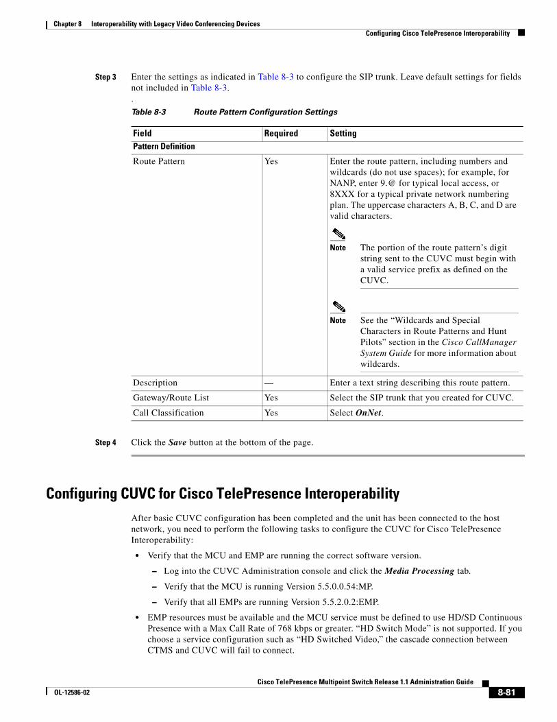
8-81Cisco TelePresence Multipoint Switch Release 1.1 Administration Guide
OL-12586-02
Chapter 8 Interoperability with Legacy Video Conferencing Devices Configuring Cisco TelePresence Interoperability
Step 3 Enter the settings as indicated in Table 8-3 to configure the SIP trunk. Leave default settings for fields not included in Table 8-3..
Step 4 Click the Save button at the bottom of the page.
Configuring CUVC for Cisco TelePresence InteroperabilityAfter basic CUVC configuration has been completed and the unit has been connected to the host network, you need to perform the following tasks to configure the CUVC for Cisco TelePresence Interoperability:
• Verify that the MCU and EMP are running the correct software version.
– Log into the CUVC Administration console and click the Media Processing tab.
– Verify that the MCU is running Version 5.5.0.0.54:MP.
– Verify that all EMPs are running Version 5.5.2.0.2:EMP.
• EMP resources must be available and the MCU service must be defined to use HD/SD Continuous Presence with a Max Call Rate of 768 kbps or greater. “HD Switch Mode” is not supported. If you choose a service configuration such as “HD Switched Video,” the cascade connection between CTMS and CUVC will fail to connect.
Table 8-3 Route Pattern Configuration Settings
Field Required SettingPattern Definition
Route Pattern Yes Enter the route pattern, including numbers and wildcards (do not use spaces); for example, for NANP, enter 9.@ for typical local access, or 8XXX for a typical private network numbering plan. The uppercase characters A, B, C, and D are valid characters.
Note The portion of the route pattern’s digit string sent to the CUVC must begin with a valid service prefix as defined on the CUVC.
Note See the “Wildcards and Special Characters in Route Patterns and Hunt Pilots” section in the Cisco CallManager System Guide for more information about wildcards.
Description — Enter a text string describing this route pattern.
Gateway/Route List Yes Select the SIP trunk that you created for CUVC.
Call Classification Yes Select OnNet.
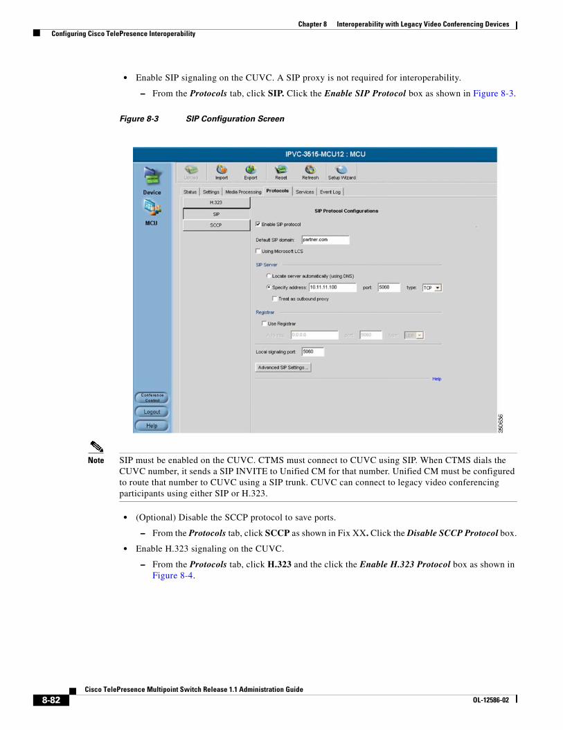
8-82Cisco TelePresence Multipoint Switch Release 1.1 Administration Guide
OL-12586-02
Chapter 8 Interoperability with Legacy Video Conferencing Devices Configuring Cisco TelePresence Interoperability
• Enable SIP signaling on the CUVC. A SIP proxy is not required for interoperability.
– From the Protocols tab, click SIP. Click the Enable SIP Protocol box as shown in Figure 8-3.
Figure 8-3 SIP Configuration Screen
Note SIP must be enabled on the CUVC. CTMS must connect to CUVC using SIP. When CTMS dials the CUVC number, it sends a SIP INVITE to Unified CM for that number. Unified CM must be configured to route that number to CUVC using a SIP trunk. CUVC can connect to legacy video conferencing participants using either SIP or H.323.
• (Optional) Disable the SCCP protocol to save ports.
– From the Protocols tab, click SCCP as shown in Fix XX. Click the Disable SCCP Protocol box.
• Enable H.323 signaling on the CUVC.
– From the Protocols tab, click H.323 and the click the Enable H.323 Protocol box as shown in Figure 8-4.
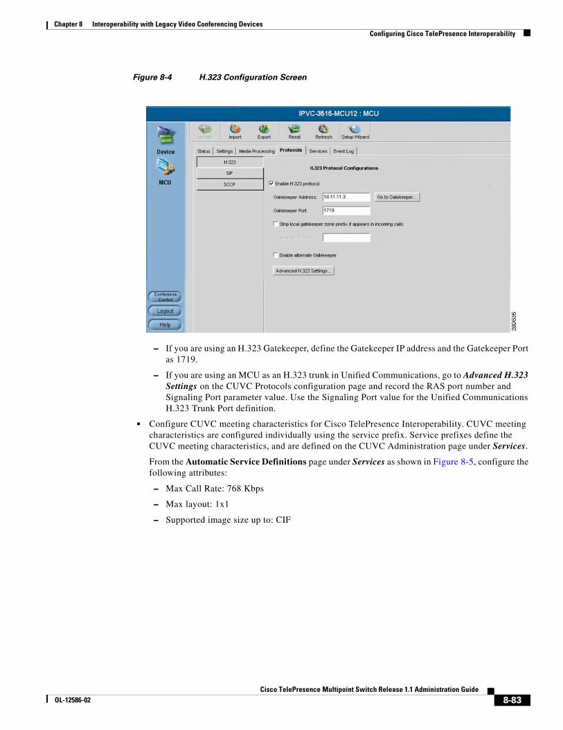
8-83Cisco TelePresence Multipoint Switch Release 1.1 Administration Guide
OL-12586-02
Chapter 8 Interoperability with Legacy Video Conferencing Devices Configuring Cisco TelePresence Interoperability
Figure 8-4 H.323 Configuration Screen
– If you are using an H.323 Gatekeeper, define the Gatekeeper IP address and the Gatekeeper Port as 1719.
– If you are using an MCU as an H.323 trunk in Unified Communications, go to Advanced H.323 Settings on the CUVC Protocols configuration page and record the RAS port number and Signaling Port parameter value. Use the Signaling Port value for the Unified Communications H.323 Trunk Port definition.
• Configure CUVC meeting characteristics for Cisco TelePresence Interoperability. CUVC meeting characteristics are configured individually using the service prefix. Service prefixes define the CUVC meeting characteristics, and are defined on the CUVC Administration page under Services.
From the Automatic Service Definitions page under Services as shown in Figure 8-5, configure the following attributes:
– Max Call Rate: 768 Kbps
– Max layout: 1x1
– Supported image size up to: CIF
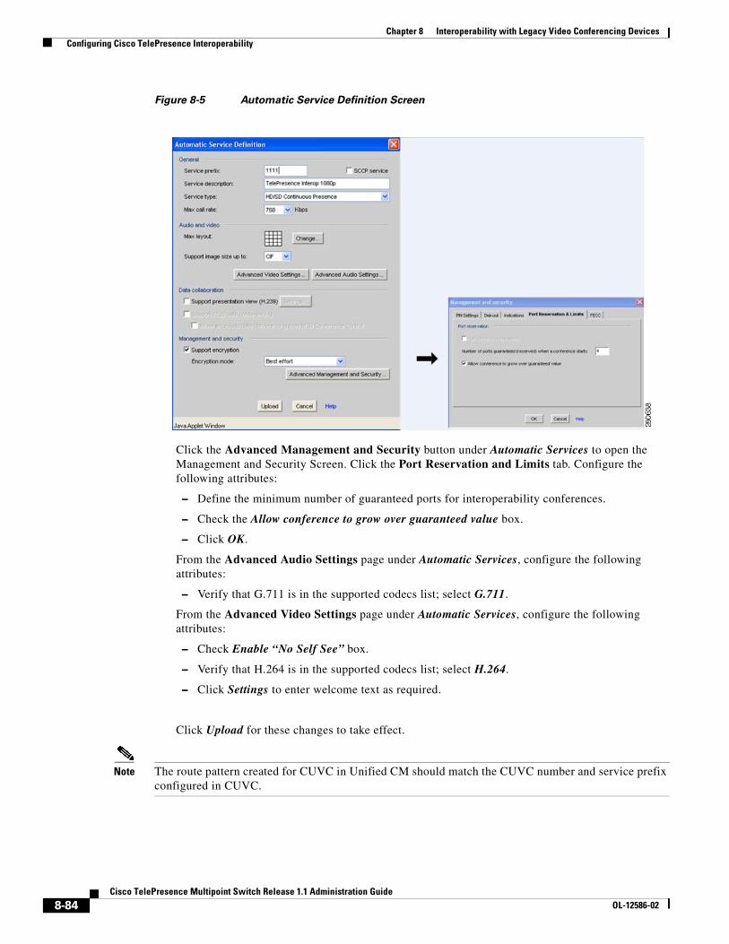
8-84Cisco TelePresence Multipoint Switch Release 1.1 Administration Guide
OL-12586-02
Chapter 8 Interoperability with Legacy Video Conferencing Devices Configuring Cisco TelePresence Interoperability
Figure 8-5 Automatic Service Definition Screen
Click the Advanced Management and Security button under Automatic Services to open the Management and Security Screen. Click the Port Reservation and Limits tab. Configure the following attributes:
– Define the minimum number of guaranteed ports for interoperability conferences.
– Check the Allow conference to grow over guaranteed value box.
– Click OK.
From the Advanced Audio Settings page under Automatic Services, configure the following attributes:
– Verify that G.711 is in the supported codecs list; select G.711.
From the Advanced Video Settings page under Automatic Services, configure the following attributes:
– Check Enable “No Self See” box.
– Verify that H.264 is in the supported codecs list; select H.264.
– Click Settings to enter welcome text as required.
Click Upload for these changes to take effect.
Note The route pattern created for CUVC in Unified CM should match the CUVC number and service prefix configured in CUVC.
8-85Cisco TelePresence Multipoint Switch Release 1.1 Administration Guide
OL-12586-02
Chapter 8 Interoperability with Legacy Video Conferencing Devices Configuring Cisco TelePresence Interoperability
• Suppress reflected video for the initial caller. When a caller joins the CUVC as the first participant of a Cisco Telepresence conference, the default behavior is for that caller to see his or her own image. To have that initial caller see a black screen instead, you must suppress reflected video. To suppress the reflected video:
– From the MCU configuration page, select the Settings tab, then click Advanced. The page refreshes and displays a Command button.
– Click Commands. The Advanced Commands window appears.
– In the Commands field, enter: mc:notselfseeforfirstpart
– In the Parameter field, enter the service prefix number followed by either 0 (to deactivate) or 1 (activate) suppressed reflection.
– Click Send to issue request to the CUVC. If the command is successful, the response field indicates “OK.”
• Network Configuration: The CUVC MCU and EMP cards each have their own Ethernet cables and IP addresses. Make sure that the switch to where the two cables attach is defined to allow QoS to be passed through to the network as a trusted device. This requirement applies to all video devices including CTS and CTMS. Configuration example is as follows:
interface TenGigabitEthernet 4/2description ===connection to telepresence gateway 2===
ip address 10.xx.xx.xx 255.255.255.252ip pim sparse-dense-modemls qos trust dscp end
For general information about the CUVC configuration tasks, refer to the Configuration Guide for the Cisco Unified Videoconferencing 3545 MCU Release 5.5.
Configuring CTMS for Cisco TelePresence InteroperabilityThe next step is to configure a static meeting in CTMS in “interop mode.” When the first CTS caller joins the teleconference, CTMS dials out to the CUVC using the Interoperability number configured in the CTMS meeting definition. CTMS dials out to the CUVC using the SIP trunk defined in Unified CM. CTMS cannot use H.323 signaling for this connection. When configuring the SIP trunk, specify a device pool with a region configured for a video bandwidth of 768 kpbs or higher.
Creating Static Meetings in CTMS for Interoperability
To create a static meeting:
Step 1 Click Static Meetings under the Meetings Management folder in the Navigation Pane.
Step 2 The Static Meetings setting screen initially displays a table providing the following information about already defined static meetings.
Table 8-4 Static Meetings Table Field Descriptions
Field Description
Access Number Displays the access number that rooms call to attend this meeting.
Description Displays the defined description for this static meeting.
8-86Cisco TelePresence Multipoint Switch Release 1.1 Administration Guide
OL-12586-02
Chapter 8 Interoperability with Legacy Video Conferencing Devices Configuring Cisco TelePresence Interoperability
• To delete one of the defined static meetings, click the radio button to the left of the table entry, and then click Delete.
• To edit one of the defined static meetings, click the radio button to the left of the table entry, and then click Edit.
• To define a new static meeting, click New.
Step 3 When you click Edit or New, CTMS Administration software takes you to the Static Meeting Settings table. Enter settings as described in Table 8-5:
Switching Policy Displays the defined switching policy (site or segment) for this static meeting.
Max Rooms Displays the maximum number of sites that can participate in this static meeting.
Quality Sets the maximum bit rate and video resolution to be used for the meeting.
Interop A green check indicates that this particular Cisco TelePresence multipoint meeting supports Cisco Unified Video Conferencing (CUVC) systems (interoperability mode). A red “X” indicates that this meeting is not configured to cascade with CUVC systems.
CUVC Number (Optional) Number dialed to CUVC for interoperability meetings.
Table 8-4 Static Meetings Table Field Descriptions
Field Description
Table 8-5 Static Meeting Settings
Field or Button Setting
Access Number Defines the telephone number that participants call to attend this static meeting.
Meeting Description Text describing or identifying this static meeting. The maximum number of characters for this field is 62 characters.
Switching Policy Defines how CTMS calls are displayed during a meeting. CTMS displays active speakers on screen. There are two active speaker display options:
• Segment: (Speaker) With segment switching, each individual table segment (defined as a display and a camera) is displayed on the screen as that segment becomes the active speaker.
• Site: (Room) When you select “site,” all table segments for a particular room are displayed on screen when any segment in that room is the active speaker.
Click the appropriate radio button to select.
Note If you are running CTS 1.3 or later, you can control how Cisco TelePresence calls are displayed from the Cisco TelePresence phone interface. Press the Speaker softkey to display the active segment; press the Room softkey to display all segements from a particular site.
8-87Cisco TelePresence Multipoint Switch Release 1.1 Administration Guide
OL-12586-02
Chapter 8 Interoperability with Legacy Video Conferencing Devices Configuring Cisco TelePresence Interoperability
Maximum Rooms Defines the maximum number of Cisco TelePresence rooms allowed to dial into in a static multi-point meeting. The range for this setting is from 2 to 48.
Video Announce If this option is selected, when a new room joins the meeting, the new room is displayed on-screen for 2 seconds. Options are Yes and No. Click the appropriate radio button to select.
Hosted Meeting Hosted meetings mean that one particular room is identified as the host for a meeting; other meeting rooms will not be added to the meeting until the host room dials in. If you have selected “Video announce,” then each meeting room will be displayed in 2-second intervals in the order that they joined the meeting.
Options are Yes and No. Click the appropriate radio button to select.
Host Room Number Defines the host Cisco TelePresence System room number.
Quality This field sets the system bandwidth and screen resolution. A higher bandwidth increases video quality, but may also cause packets to be dropped and video to be interrupted. Choices:
• Highest Detail, Best Motion: 4Mbps 1080p
• Highest Detail, Better Motion: 3.5Mbps, 1080p
• Highest Detail, Good Motion: 3Mbps, 1080p
• Highest Detail, Best Motion: 3Mbps, 720p
• Highest Detail, Better Motion: 2Mbps, 720p
• Highest Detail, Good Motion: 1Mbps, 720p
Default is Highest Detail, Best Motion: 4Mbps 1080p.
Interop Determines whether this particular Cisco TelePresence multipoint meeting accepts legacy Cisco Unified Video Conferencing (CUVC) systems (interop).
Options are Yes and No. Click the appropriate radio button to select.
CUVC Number Defines the number that CTMS dials to establish contact with CUVC. Each CUVC number must be unique for each CTMS conference. The CUVC number consists of the service prefix and then the remaining dialed digits. The service prefix can be the same for different meetings. The remaining digits in the dialed number designate the CUVC meeting instance.
Each CTMS conference requires it owns CUVC meeting instance.
Note This number must start with the CUVC service prefix defined during CUVC configuration.
Table 8-5 Static Meeting Settings
Field or Button Setting
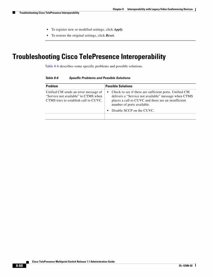
8-88Cisco TelePresence Multipoint Switch Release 1.1 Administration Guide
OL-12586-02
Chapter 8 Interoperability with Legacy Video Conferencing Devices Troubleshooting Cisco TelePresence Interoperability
• To register new or modified settings, click Apply.
• To restore the original settings, click Reset.
Troubleshooting Cisco TelePresence InteroperabilityTable 8-6 describes some specific problems and possible solutions.
Table 8-6 Specific Problems and Possible Solutions
Problem Possible Solutions
Unified CM sends an error message of “Service not available” to CTMS when CTMS tries to establish call to CUVC.
• Check to see if there are sufficient ports. Unified CM delivers a “Service not available” message when CTMS places a call to CUVC and there are an insufficient number of ports available.
• Disable SCCP on the CUVC.
A-1Cisco TelePresence System Release 1.4 Administrator’s Guide
OL-12586-02
A P P E N D I X ACommand Line Interface (CLI) Commands
Initial Release: August 4, 2008, OL-12586-02
Tables of Contents• “Introduction” section on page A-1
• “Starting a CLI Session” section on page A-1
• “CLI Command Basics” section on page A-2
• “Ending a CLI Session” section on page A-2
• “CTMS CLI Commands” section on page A-2
IntroductionThis chapter explains how to use Cisco TelePresence Multipoint Switch (CTMS) Command Line Interface (CLI) commands.
Starting a CLI SessionYou can access the CTMS CLI through the physical console or remotely. If accessing the CTMS CLI remote, use Secure Shell (SSH) from a personal computer or workstation to connect securely to CTMS.
Before you begin, be sure that you have the following information:
• CTMS IP address
• Admin ID and password
You will need this information to log into CTMS.
Note The admin ID and password can be changed from the default in the Cisco Unified Communications Manager (Unified CM) for CTMS device page.
To start a CLI session:

A-2Cisco TelePresence System Release 1.4 Administrator’s Guide
OL-12586-02
Appendix A Command Line Interface (CLI) Commands Ending a CLI Session
Step 1 From a remote system, use SSH to connect securely to CTMS. In the SSH client, enter the following information: ssh adminname@IP Address
• adminname is the Admin ID
• IP Address is the IP address of CTMS
Step 2 When the system prompts you, enter the password.
Step 3 The CLI prompt (admin) displays. You can now enter any CLI command.
Note The prompt will always be “admin.”
CLI Command Basics• Enter the beginning of a command and press Tab to have the system complete the command for you.
• Enter a full command and press Tab to display all commands or subcommands that are available. If you press Tab and the current command line repeats, no additional expansions are available.
• To get detailed help, enter help command name at the CLI prompt.
• To get command syntax for a particular command, enter command name? at the CLI prompt
Ending a CLI SessionTo end a CLI session:
Step 1 At the CLI prompt, enter quit.
CTMS CLI CommandsThe following CLI commands are used with Cisco TelePresence Multipoint Switch:
• confmgmt, page A-5
• media GetDSCP, page A-6
• set bad_ep_detect, page A-7
• set commandcount, page A-8
• set conferencetermination, page A-9
• set cuvcdialrepeatinterval, page A-10
• set cuvcdialrepeattime, page A-11
• set damping, page A-12
• set feedbackwaitbasetime, page A-13
A-3Cisco TelePresence System Release 1.4 Administrator’s Guide
OL-12586-02
Appendix A Command Line Interface (CLI) Commands CTMS CLI Commands
• set holdresume, page A-14
• set lateendmins, page A-15
• set logging, page A-16
• set network dns, page A-17
• set network ip eth0, page A-18
• set password admin, page A-19
• set timezone, page A-20
• show account, page A-21
• show active conference, page A-22
• show badep, page A-23
• show conferencetermination, page A-24
• show cuvcdialrepeatinterval, page A-25
• show cuvcdialrepeattime, page A-26
• show damping, page A-27
• show details, page A-28
• show dscp packet, page A-29
• show feedbackwaittime, page A-30
• show feedbackwaitbasetime, page A-31
• show firewall list, page A-32
• show hardware, page A-35
• show holdresume, page A-36
• show lateendmins, page A-37
• show logins, page A-38
• show myself, page A-39
• show network all, page A-40
• show network eth0, page A-42
• show network failover, page A-43
• show network ip_conntrack, page A-44
• show network max_ip_conntrack, page A-45
• show network route, page A-46
• show network status, page A-47
• show packages, page A-48
• show rtpsleep, page A-49
• show statistics, page A-50
• show status, page A-53
• show threshold, page A-55
• show timezone, page A-56
• show version, page A-58
A-4Cisco TelePresence System Release 1.4 Administrator’s Guide
OL-12586-02
Appendix A Command Line Interface (CLI) Commands CTMS CLI Commands
• show workingdir, page A-59
• utils remote_account, page A-60
• utils remote_account create, page A-61
• utils remote_account status, page A-62
• utils system restart, page A-63
• utils system shutdown, page A-64
• utils system switch-version, page A-65
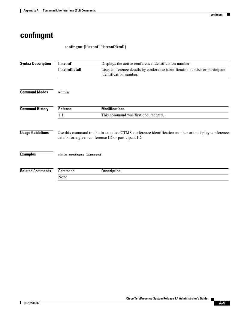
A-5Cisco TelePresence System Release 1.4 Administrator’s Guide
OL-12586-02
Appendix A Command Line Interface (CLI) Commands confmgmt
confmgmtconfmgmt {listconf | listconfdetail}
Syntax Description
Command Modes Admin
Command History
Usage Guidelines Use this command to obtain an active CTMS conference identification number or to display conference details for a given conference ID or participant ID.
Examples admin:confmgmt listconf
Related Commands
listconf Displays the active conference identification number.
listconfdetail Lists conference details by conference identification number or participant identification number.
Release Modifications
1.1 This command was first documented.
Command Description
None
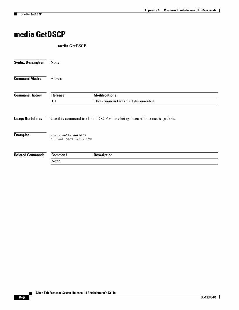
A-6Cisco TelePresence System Release 1.4 Administrator’s Guide
OL-12586-02
Appendix A Command Line Interface (CLI) Commands media GetDSCP
media GetDSCPmedia GetDSCP
Syntax Description None
Command Modes Admin
Command History
Usage Guidelines Use this command to obtain DSCP values being inserted into media packets.
Examples admin:media GetDSCPCurrent DSCP value:128
Related Commands
Release Modifications
1.1 This command was first documented.
Command Description
None
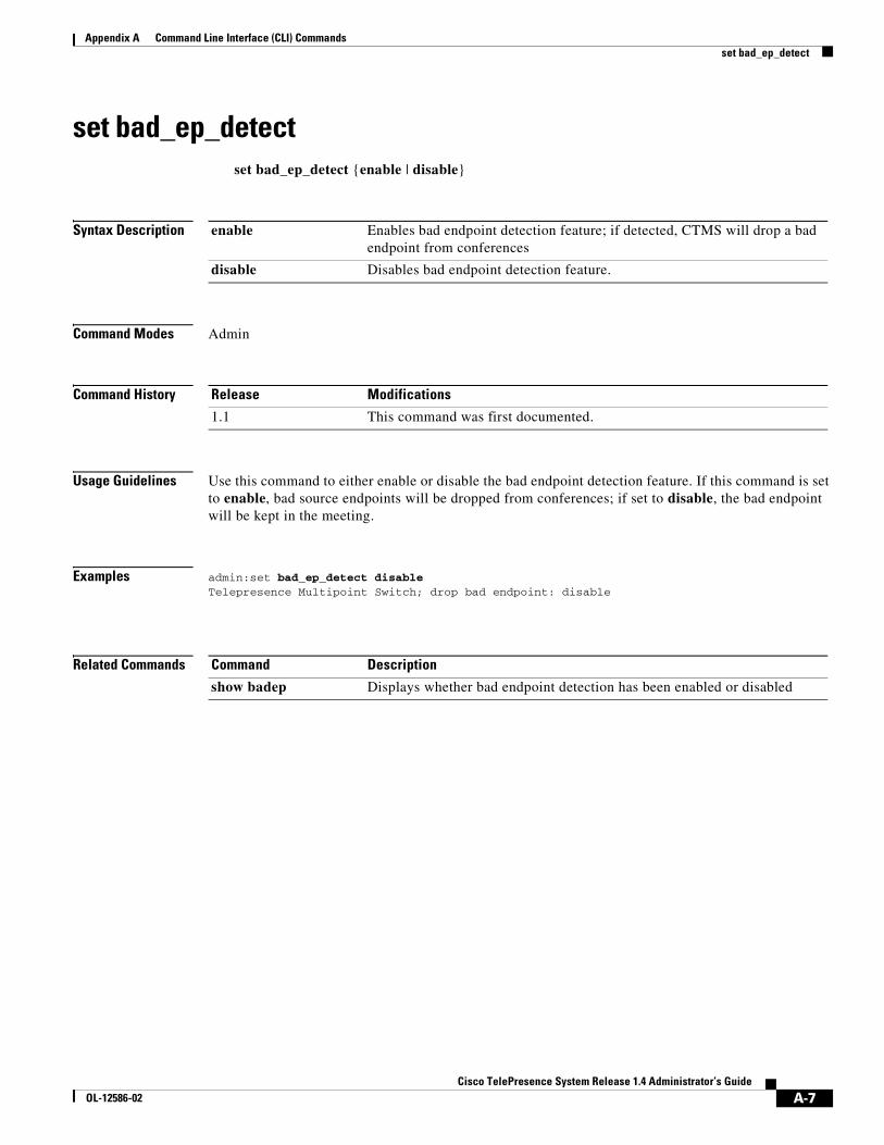
A-7Cisco TelePresence System Release 1.4 Administrator’s Guide
OL-12586-02
Appendix A Command Line Interface (CLI) Commands set bad_ep_detect
set bad_ep_detectset bad_ep_detect {enable | disable}
Syntax Description
Command Modes Admin
Command History
Usage Guidelines Use this command to either enable or disable the bad endpoint detection feature. If this command is set to enable, bad source endpoints will be dropped from conferences; if set to disable, the bad endpoint will be kept in the meeting.
Examples admin:set bad_ep_detect disableTelepresence Multipoint Switch; drop bad endpoint: disable
Related Commands
enable Enables bad endpoint detection feature; if detected, CTMS will drop a bad endpoint from conferences
disable Disables bad endpoint detection feature.
Release Modifications
1.1 This command was first documented.
Command Description
show badep Displays whether bad endpoint detection has been enabled or disabled
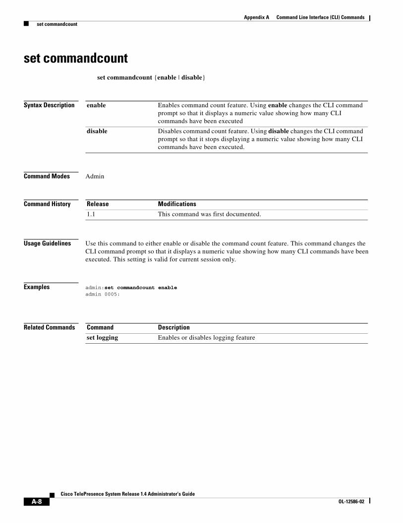
A-8Cisco TelePresence System Release 1.4 Administrator’s Guide
OL-12586-02
Appendix A Command Line Interface (CLI) Commands set commandcount
set commandcountset commandcount {enable | disable}
Syntax Description
Command Modes Admin
Command History
Usage Guidelines Use this command to either enable or disable the command count feature. This command changes the CLI command prompt so that it displays a numeric value showing how many CLI commands have been executed. This setting is valid for current session only.
Examples admin:set commandcount enableadmin 0005:
Related Commands
enable Enables command count feature. Using enable changes the CLI command prompt so that it displays a numeric value showing how many CLI commands have been executed
disable Disables command count feature. Using disable changes the CLI command prompt so that it stops displaying a numeric value showing how many CLI commands have been executed.
Release Modifications
1.1 This command was first documented.
Command Description
set logging Enables or disables logging feature
A-9Cisco TelePresence System Release 1.4 Administrator’s Guide
OL-12586-02
Appendix A Command Line Interface (CLI) Commands set conferencetermination
set conferenceterminationset conferencetermination {true | false}
Syntax Description
Command Modes Admin
Command History
Usage Guidelines Use this command to either enable or disable conference termination for scheduled conferences.
Note This command takes effect when CTMS is registered with Cisco TelePresence Manager but not supported by Cisco TelePresence Manager.
Examples admin:set conferencetermination true
Related Commands
true Enables conference termination for scheduled conferences.
false Disables conference termination for scheduled conferences.
Release Modifications
1.1 This command was first documented.
Command Description
show conferencetermination
Displays list of conferences with enabled or disabled conference termination
A-10Cisco TelePresence System Release 1.4 Administrator’s Guide
OL-12586-02
Appendix A Command Line Interface (CLI) Commands set cuvcdialrepeatinterval
set cuvcdialrepeatintervalset cuvcdialrepeatinterval number
Syntax Description
Command Modes Admin
Command History
Usage Guidelines Use this command to configure the time (in seconds) for CTMS to redial a CUVC participant.
Examples admin: set cuvcdialrepeatinterval 30
Related Commands
number Length of time, in seconds, that the CTMS system waits between redialing the CUVC. The default is 30.
Release Modifications
1.1 This command was first documented.
Command Description
set cuvcdialrepeattime Configures the number of times CTMS redials a CUVC participant
A-11Cisco TelePresence System Release 1.4 Administrator’s Guide
OL-12586-02
Appendix A Command Line Interface (CLI) Commands set cuvcdialrepeattime
set cuvcdialrepeattimeset cuvcdialrepeattime number
Syntax Description
Command Modes Admin
Command History
Usage Guidelines Use this command to configure the number of times CTMS will redial a CTMS meeting participant.
Examples admin: set cuvcdialrepeattime 10
Related Commands
number Number of times CTMS will redial a CUVC meeting participant. The default is 50.
Release Modifications
1.1 This command was first documented.
Command Description
set cuvcdialrepeatinterval
Configures the time (in seconds) for CTMS to redial a CUVC participant
A-12Cisco TelePresence System Release 1.4 Administrator’s Guide
OL-12586-02
Appendix A Command Line Interface (CLI) Commands set damping
set dampingset damping {s | l | b | o} {fast | medium | slow}
Syntax Description
Command Modes Admin
Command History
Usage Guidelines Use this command to set damping values for switching.
Examples admin:set damping s fast
Related Commands
s Switching mode; switching damping refers to how long people must talk to be switched in as active speaker.
l Lecture mode; lecture damping refers to how long somebody other than the lecturer must talk to take the conference out of lecture mode.
b Bounce mode; bounce damping refers to how long somebody must talk to override a bounceback source.
o Override mode; override damping refers to how long, after being overridden, a bounceback source is switched back in.
fast Fast mode speed: .5 to 1.5 seconds
medium Medium mode speed: 1.5 to 2.5 seconds
slow Slow mode speed: 2.5 to 3.5 seconds
Release Modifications
1.1 This command was first documented.
Command Description
show damping Displays damping speeds for configured damping modes.
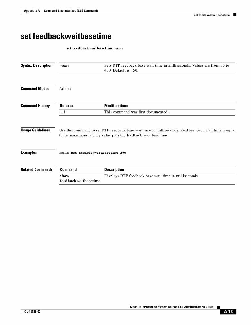
A-13Cisco TelePresence System Release 1.4 Administrator’s Guide
OL-12586-02
Appendix A Command Line Interface (CLI) Commands set feedbackwaitbasetime
set feedbackwaitbasetimeset feedbackwaitbasetime value
Syntax Description
Command Modes Admin
Command History
Usage Guidelines Use this command to set RTP feedback base wait time in milliseconds. Real feedback wait time is equal to the maximum latency value plus the feedback wait base time.
Examples admin:set feedbackwaitbasetime 200
Related Commands
value Sets RTP feedback base wait time in milliseconds. Values are from 30 to 400. Default is 150.
Release Modifications
1.1 This command was first documented.
Command Description
show feedbackwaitbasetime
Displays RTP feedback base wait time in milliseconds
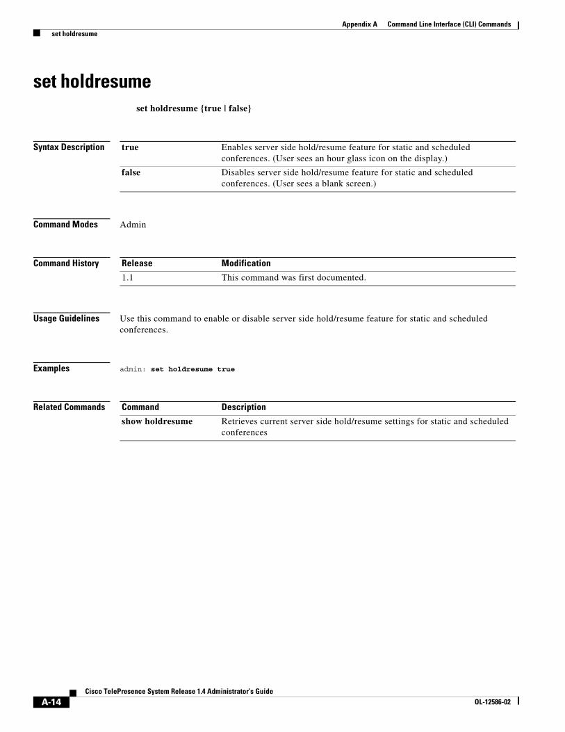
A-14Cisco TelePresence System Release 1.4 Administrator’s Guide
OL-12586-02
Appendix A Command Line Interface (CLI) Commands set holdresume
set holdresumeset holdresume {true | false}
Syntax Description
Command Modes Admin
Command History
Usage Guidelines Use this command to enable or disable server side hold/resume feature for static and scheduled conferences.
Examples admin: set holdresume true
Related Commands
true Enables server side hold/resume feature for static and scheduled conferences. (User sees an hour glass icon on the display.)
false Disables server side hold/resume feature for static and scheduled conferences. (User sees a blank screen.)
Release Modification
1.1 This command was first documented.
Command Description
show holdresume Retrieves current server side hold/resume settings for static and scheduled conferences
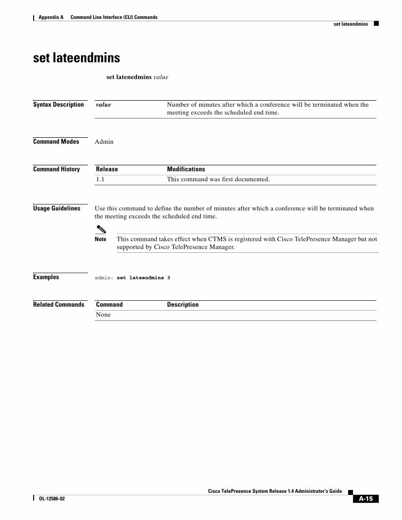
A-15Cisco TelePresence System Release 1.4 Administrator’s Guide
OL-12586-02
Appendix A Command Line Interface (CLI) Commands set lateendmins
set lateendminsset latenedmins value
Syntax Description
Command Modes Admin
Command History
Usage Guidelines Use this command to define the number of minutes after which a conference will be terminated when the meeting exceeds the scheduled end time.
Note This command takes effect when CTMS is registered with Cisco TelePresence Manager but not supported by Cisco TelePresence Manager.
Examples admin: set lateendmins 3
Related Commands
value Number of minutes after which a conference will be terminated when the meeting exceeds the scheduled end time.
Release Modifications
1.1 This command was first documented.
Command Description
None
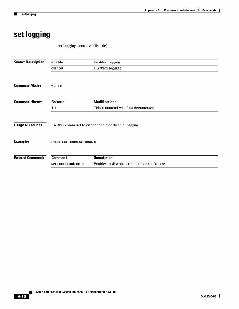
A-16Cisco TelePresence System Release 1.4 Administrator’s Guide
OL-12586-02
Appendix A Command Line Interface (CLI) Commands set logging
set loggingset logging {enable | disable}
Syntax Description
Command Modes Admin
Command History
Usage Guidelines Use this command to either enable or disable logging.
Examples admin:set logging enable
Related Commands
enable Enables logging.
disable Disables logging.
Release Modifications
1.1 This command was first documented.
Command Description
set commandcount Enables or disables command count feature
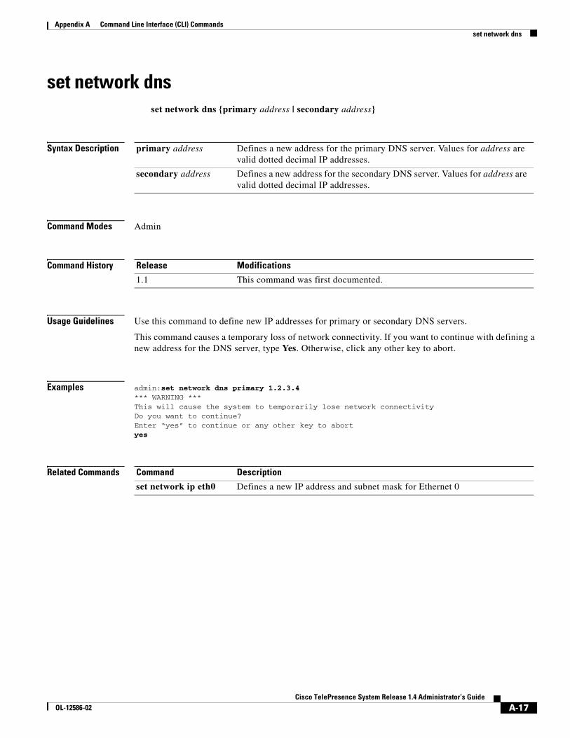
A-17Cisco TelePresence System Release 1.4 Administrator’s Guide
OL-12586-02
Appendix A Command Line Interface (CLI) Commands set network dns
set network dnsset network dns {primary address | secondary address}
Syntax Description
Command Modes Admin
Command History
Usage Guidelines Use this command to define new IP addresses for primary or secondary DNS servers.
This command causes a temporary loss of network connectivity. If you want to continue with defining a new address for the DNS server, type Yes. Otherwise, click any other key to abort.
Examples admin:set network dns primary 1.2.3.4*** WARNING ***This will cause the system to temporarily lose network connectivityDo you want to continue?Enter “yes” to continue or any other key to abortyes
Related Commands
primary address Defines a new address for the primary DNS server. Values for address are valid dotted decimal IP addresses.
secondary address Defines a new address for the secondary DNS server. Values for address are valid dotted decimal IP addresses.
Release Modifications
1.1 This command was first documented.
Command Description
set network ip eth0 Defines a new IP address and subnet mask for Ethernet 0
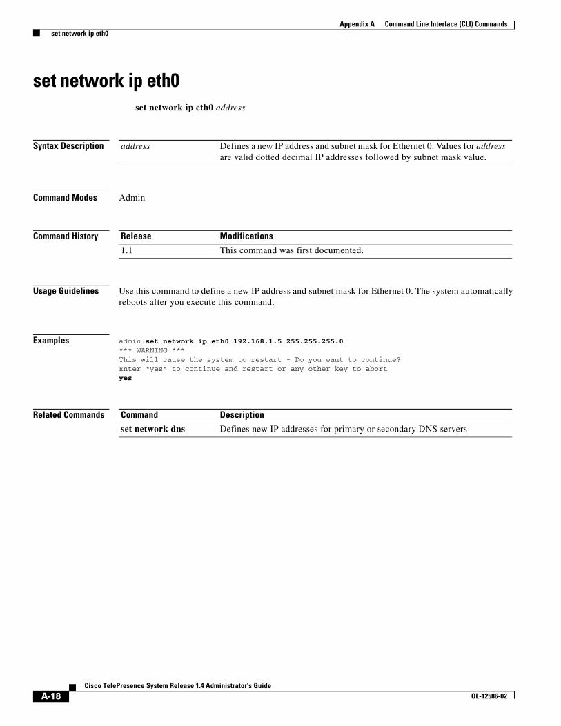
A-18Cisco TelePresence System Release 1.4 Administrator’s Guide
OL-12586-02
Appendix A Command Line Interface (CLI) Commands set network ip eth0
set network ip eth0set network ip eth0 address
Syntax Description
Command Modes Admin
Command History
Usage Guidelines Use this command to define a new IP address and subnet mask for Ethernet 0. The system automatically reboots after you execute this command.
Examples admin:set network ip eth0 192.168.1.5 255.255.255.0*** WARNING ***This will cause the system to restart - Do you want to continue?Enter “yes” to continue and restart or any other key to abortyes
Related Commands
address Defines a new IP address and subnet mask for Ethernet 0. Values for address are valid dotted decimal IP addresses followed by subnet mask value.
Release Modifications
1.1 This command was first documented.
Command Description
set network dns Defines new IP addresses for primary or secondary DNS servers

A-19Cisco TelePresence System Release 1.4 Administrator’s Guide
OL-12586-02
Appendix A Command Line Interface (CLI) Commands set password admin
set password adminset password admin
Syntax Description None
Command Modes Admin
Command History
Usage Guidelines Use this command to set a new administrator password.
Note Passwords must be at least 6 characters, but not more than 64 characters in length, and can contain upper and lower case alphanumeric characters and the underscore and dash characters. The following usernames are not allowed: apache, daemon, nobody, operator, and shutdown.
Examples admin:set password adminPlease enter the old password: ******Please enter the new password: ********Re-enter new password to confirm: ********
Related Commands
Command Modifications
1.1 This command was first documented.
Command Description
None
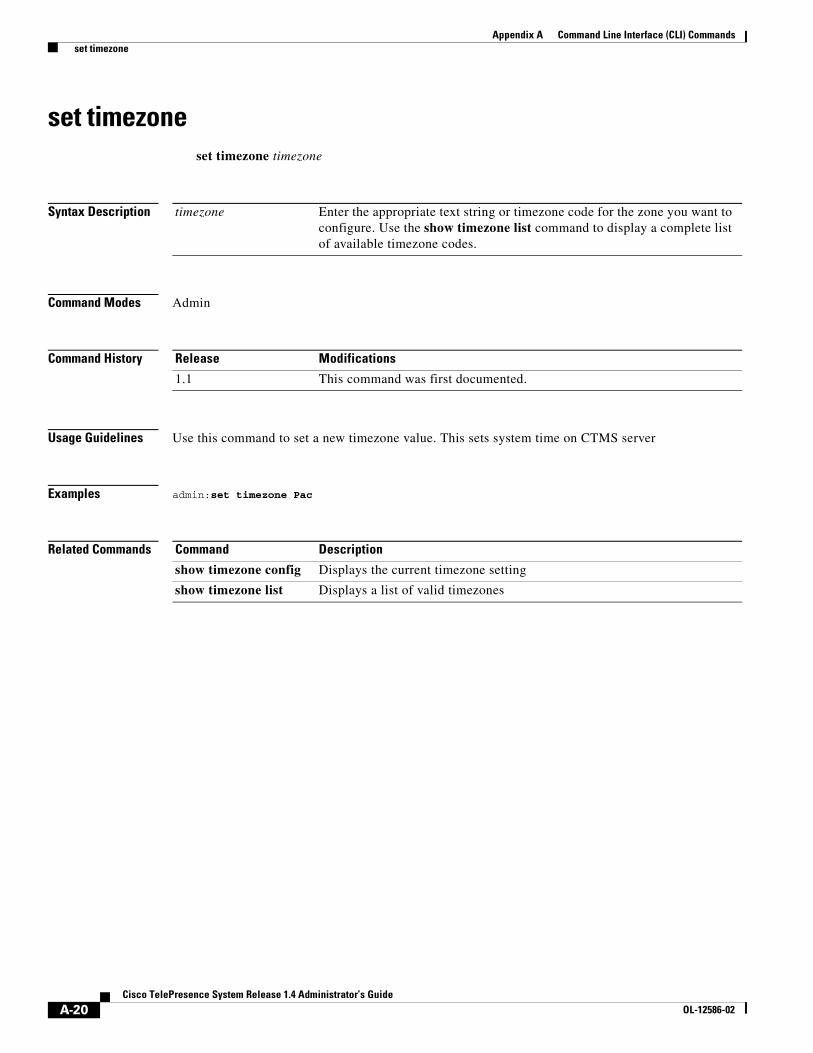
A-20Cisco TelePresence System Release 1.4 Administrator’s Guide
OL-12586-02
Appendix A Command Line Interface (CLI) Commands set timezone
set timezoneset timezone timezone
Syntax Description
Command Modes Admin
Command History
Usage Guidelines Use this command to set a new timezone value. This sets system time on CTMS server
Examples admin:set timezone Pac
Related Commands
timezone Enter the appropriate text string or timezone code for the zone you want to configure. Use the show timezone list command to display a complete list of available timezone codes.
Release Modifications
1.1 This command was first documented.
Command Description
show timezone config Displays the current timezone setting
show timezone list Displays a list of valid timezones
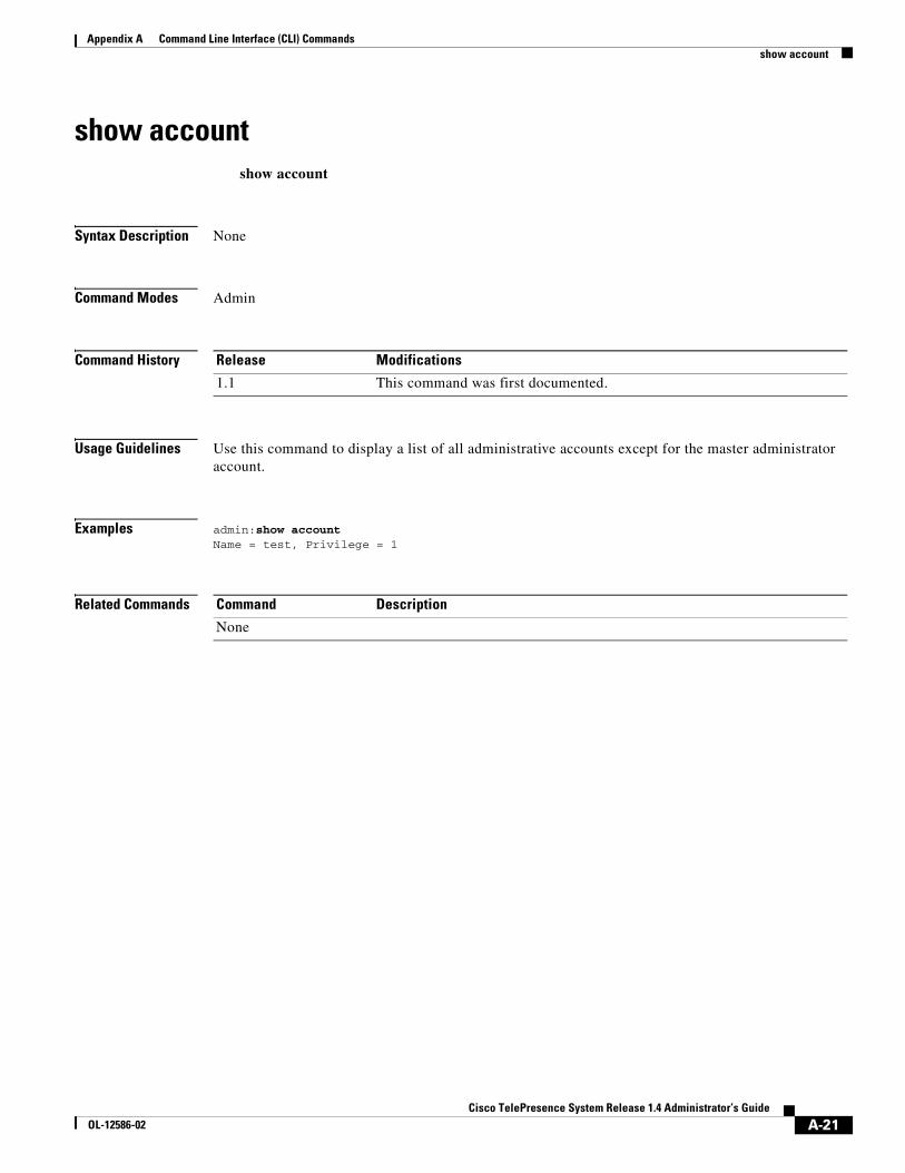
A-21Cisco TelePresence System Release 1.4 Administrator’s Guide
OL-12586-02
Appendix A Command Line Interface (CLI) Commands show account
show accountshow account
Syntax Description None
Command Modes Admin
Command History
Usage Guidelines Use this command to display a list of all administrative accounts except for the master administrator account.
Examples admin:show accountName = test, Privilege = 1
Related Commands
Release Modifications
1.1 This command was first documented.
Command Description
None

A-22Cisco TelePresence System Release 1.4 Administrator’s Guide
OL-12586-02
Appendix A Command Line Interface (CLI) Commands show active conference
show active conferenceshow active conference
Syntax Description None
Command Modes Admin
Command History
Usage Guidelines Use this command to display a list of active conference identification numbers.
Examples admin:show active conference9059578056
Related Commands
Release Modifications
1.1 This command was first documented.
Command Description
None

A-23Cisco TelePresence System Release 1.4 Administrator’s Guide
OL-12586-02
Appendix A Command Line Interface (CLI) Commands show badep
show badepshow badep
Syntax Description None
Command Modes Admin
Command History
Usage Guidelines Use this command to display whether bad endpoint detection is enabled or disabled.
Examples admin:show badepCurrent setting to drop bad endpoint: enable
Related Commands
Release Modifications
1.1 This command was first documented.
Command Description
set bad_ep_detect Enables or disabled bad endpoint detection
A-24Cisco TelePresence System Release 1.4 Administrator’s Guide
OL-12586-02
Appendix A Command Line Interface (CLI) Commands show conferencetermination
show conferenceterminationshow conferencetermination
Syntax Description None
Command Modes Admin
Command History
Usage Guidelines Use this command to display a list of conferences with enabled or disabled conference termination.
Examples admin: show conferencetermination
Related Commands
Release Modifications
1.1 This command was first documented.
Command Description
set conferencetermination
Enables or disables conference termination for scheduled conferences
A-25Cisco TelePresence System Release 1.4 Administrator’s Guide
OL-12586-02
Appendix A Command Line Interface (CLI) Commands show cuvcdialrepeatinterval
show cuvcdialrepeatintervalshow cuvcdialrepeatinterval
Syntax Description None
Command Modes Admin
Command History
Usage Guidelines Use this command to view the CUVC redial time in seconds.
Examples admin: show cuvcdialrepeatinterval
Related Commands
Release Modifications
1.1 This command was first documented.
Command Description
show cuvcdialrepeattime
Displays configured CUVC redial retries
A-26Cisco TelePresence System Release 1.4 Administrator’s Guide
OL-12586-02
Appendix A Command Line Interface (CLI) Commands show cuvcdialrepeattime
show cuvcdialrepeattimeshow cuvcdialrepeattime
Syntax Description None
Command Modes Admin
Command History
Usage Guidelines Use this command to view configured CUVC redial retry value.
Examples admin:show cuvcdialrepeattime cuvc retry time is 50
Related Commands
Release Modifications
1.1 This command was first documented.
Command Description
show cuvcdialrepeatinterval
Displays the CUVC redial time in seconds
A-27Cisco TelePresence System Release 1.4 Administrator’s Guide
OL-12586-02
Appendix A Command Line Interface (CLI) Commands show damping
show dampingshow damping {s | l | b | o}
Syntax Description
Command Modes Admin
Command History
Usage Guidelines Use this command to display damping speeds for defined damping modes.
Examples admin:show damping sDamping time is currently set to mediumadmin:show damping lLecture damping time is currently set to medium
Related Commands
s Switching mode; switching damping refers to how long people must talk to be switched in as active speaker.
l Lecture mode; lecture damping refers to how long somebody other than the lecturer must talk to take the conference out of lecture mode.
b Bounce mode; bounce damping refers to how long somebody must talk to override a bounceback source.
o Override mode; override damping refers to how long, after being overridden, a bounceback source is switched back in.
Release Modifications
1.1 This command was first documented.
Command Descriptions
set damping Sets damping values for switching.
A-28Cisco TelePresence System Release 1.4 Administrator’s Guide
OL-12586-02
Appendix A Command Line Interface (CLI) Commands show details
show detailsshow details {conference | participant}
Syntax Description
Command Modes Admin
Command History
Usage Guidelines Use this command to list conference details either by conference identification number or by participant identification number.
Examples admin:show details conference 9059578056Conference Id: 9059578056Conference type: ImmediateParticipant list: 11080, 11081, 11082Conference description: TESTINGSwitching policy: SITEAutoLecture Mode: falseVideo Announce: trueTotal segments: 3Resolution & Bandwidth: 1080p 4MBpsIsLocked: false
Related Commands
conference Conference identification number
participant Participant identification number.
Release Modifications
1.1 This command was first documented.
Command Description
None
A-29Cisco TelePresence System Release 1.4 Administrator’s Guide
OL-12586-02
Appendix A Command Line Interface (CLI) Commands show dscp packet
show dscp packetshow dscp packet
Syntax Description None
Command Modes Admin
Command History
Usage Guidelines Use this command to display configured DSCP values being inserted in media packets.
Examples admin:show dscp packetCurrent DSCP value:128
Related Commands
Release Modifications
1.1 This command was first documented.
Command Description
None
A-30Cisco TelePresence System Release 1.4 Administrator’s Guide
OL-12586-02
Appendix A Command Line Interface (CLI) Commands show feedbackwaittime
show feedbackwaittimeset feedbackwaittime confid number
Syntax Description
Command Modes Admin
Command History
Usage Guidelines Use this command to return feedback wait time information for a conference in milliseconds. Feedback wait time is equal to maximum latency per conference plus feedback wait base time.
Examples admin:show feedbackwaittime 9059578056FBWaitTime=254
Related Commands
confid number Conference identification number
Release Modifications
1.1 This command was first documented.
Command Description
set feedbackwaitbasetime
Set RTPs feedback base wait time in milliseconds
show feedbackwaitbasetime
Displays RTP feedback base wait time in milliseconds
A-31Cisco TelePresence System Release 1.4 Administrator’s Guide
OL-12586-02
Appendix A Command Line Interface (CLI) Commands show feedbackwaitbasetime
show feedbackwaitbasetimeshow feedbackwaitbasetime
Syntax Description None
Command Modes Admin
Command History
Usage Guidelines Use this command to display RTP feedback base wait time in milliseconds.
Examples admin:show feedbackwaitbasetime Current Feedback wait base time is 250 ms
Related Commands
Release Modifications
1.1 This command was first documented.
Command Description
set feedbackwaitbasetime
Set RTPs feedback base wait time in milliseconds
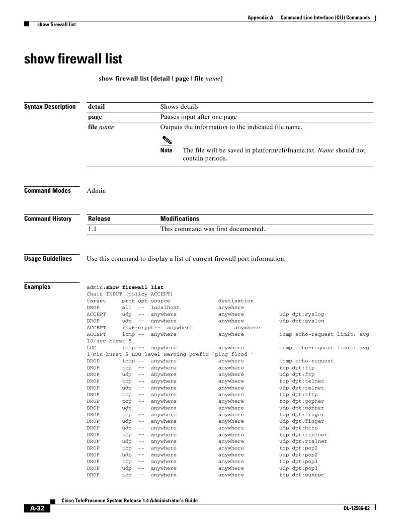
A-32Cisco TelePresence System Release 1.4 Administrator’s Guide
OL-12586-02
Appendix A Command Line Interface (CLI) Commands show firewall list
show firewall listshow firewall list [detail | page | file name]
Syntax Description
Command Modes Admin
Command History
Usage Guidelines Use this command to display a list of current firewall port information.
Examples admin:show firewall list Chain INPUT (policy ACCEPT)target prot opt source destination DROP all -- localhost anywhere ACCEPT udp -- anywhere anywhere udp dpt:syslog DROP udp -- anywhere anywhere udp dpt:syslog ACCEPT ipv6-crypt-- anywhere anywhere ACCEPT icmp -- anywhere anywhere icmp echo-request limit: avg 10/sec burst 5 LOG icmp -- anywhere anywhere icmp echo-request limit: avg 1/min burst 5 LOG level warning prefix `ping flood ' DROP icmp -- anywhere anywhere icmp echo-request DROP tcp -- anywhere anywhere tcp dpt:ftp DROP udp -- anywhere anywhere udp dpt:ftp DROP tcp -- anywhere anywhere tcp dpt:telnet DROP udp -- anywhere anywhere udp dpt:telnet DROP tcp -- anywhere anywhere tcp dpt:tftp DROP tcp -- anywhere anywhere tcp dpt:gopher DROP udp -- anywhere anywhere udp dpt:gopher DROP tcp -- anywhere anywhere tcp dpt:finger DROP udp -- anywhere anywhere udp dpt:finger DROP udp -- anywhere anywhere udp dpt:http DROP tcp -- anywhere anywhere tcp dpt:rtelnet DROP udp -- anywhere anywhere udp dpt:rtelnet DROP tcp -- anywhere anywhere tcp dpt:pop2 DROP udp -- anywhere anywhere udp dpt:pop2 DROP tcp -- anywhere anywhere tcp dpt:pop3 DROP udp -- anywhere anywhere udp dpt:pop3 DROP tcp -- anywhere anywhere tcp dpt:sunrpc
detail Shows details
page Pauses input after one page
file name Outputs the information to the indicated file name.
Note The file will be saved in platform/cli/fname.txt. Name should not contain periods.
Release Modifications
1.1 This command was first documented.
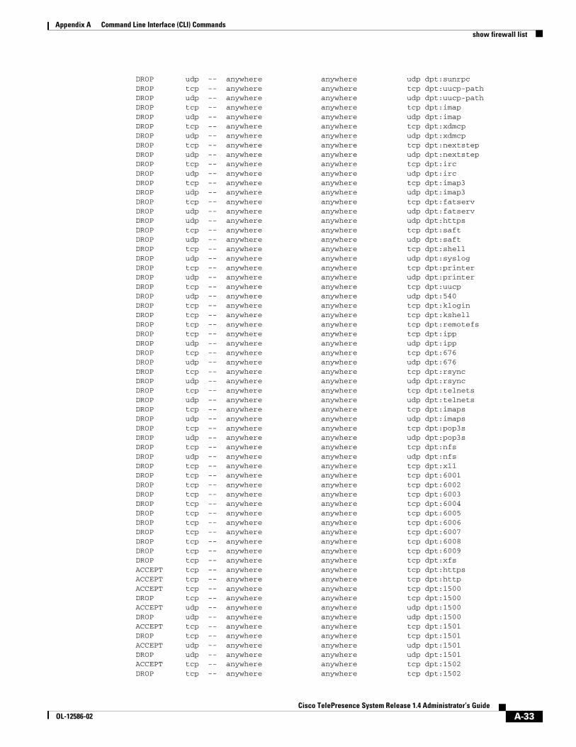
A-33Cisco TelePresence System Release 1.4 Administrator’s Guide
OL-12586-02
Appendix A Command Line Interface (CLI) Commands show firewall list
DROP udp -- anywhere anywhere udp dpt:sunrpc DROP tcp -- anywhere anywhere tcp dpt:uucp-path DROP udp -- anywhere anywhere udp dpt:uucp-path DROP tcp -- anywhere anywhere tcp dpt:imap DROP udp -- anywhere anywhere udp dpt:imap DROP tcp -- anywhere anywhere tcp dpt:xdmcp DROP udp -- anywhere anywhere udp dpt:xdmcp DROP tcp -- anywhere anywhere tcp dpt:nextstep DROP udp -- anywhere anywhere udp dpt:nextstep DROP tcp -- anywhere anywhere tcp dpt:irc DROP udp -- anywhere anywhere udp dpt:irc DROP tcp -- anywhere anywhere tcp dpt:imap3 DROP udp -- anywhere anywhere udp dpt:imap3 DROP tcp -- anywhere anywhere tcp dpt:fatserv DROP udp -- anywhere anywhere udp dpt:fatserv DROP udp -- anywhere anywhere udp dpt:https DROP tcp -- anywhere anywhere tcp dpt:saft DROP udp -- anywhere anywhere udp dpt:saft DROP tcp -- anywhere anywhere tcp dpt:shell DROP udp -- anywhere anywhere udp dpt:syslog DROP tcp -- anywhere anywhere tcp dpt:printer DROP udp -- anywhere anywhere udp dpt:printer DROP tcp -- anywhere anywhere tcp dpt:uucp DROP udp -- anywhere anywhere udp dpt:540 DROP tcp -- anywhere anywhere tcp dpt:klogin DROP tcp -- anywhere anywhere tcp dpt:kshell DROP tcp -- anywhere anywhere tcp dpt:remotefs DROP tcp -- anywhere anywhere tcp dpt:ipp DROP udp -- anywhere anywhere udp dpt:ipp DROP tcp -- anywhere anywhere tcp dpt:676 DROP udp -- anywhere anywhere udp dpt:676 DROP tcp -- anywhere anywhere tcp dpt:rsync DROP udp -- anywhere anywhere udp dpt:rsync DROP tcp -- anywhere anywhere tcp dpt:telnets DROP udp -- anywhere anywhere udp dpt:telnets DROP tcp -- anywhere anywhere tcp dpt:imaps DROP udp -- anywhere anywhere udp dpt:imaps DROP tcp -- anywhere anywhere tcp dpt:pop3s DROP udp -- anywhere anywhere udp dpt:pop3s DROP tcp -- anywhere anywhere tcp dpt:nfs DROP udp -- anywhere anywhere udp dpt:nfs DROP tcp -- anywhere anywhere tcp dpt:x11 DROP tcp -- anywhere anywhere tcp dpt:6001 DROP tcp -- anywhere anywhere tcp dpt:6002 DROP tcp -- anywhere anywhere tcp dpt:6003 DROP tcp -- anywhere anywhere tcp dpt:6004 DROP tcp -- anywhere anywhere tcp dpt:6005 DROP tcp -- anywhere anywhere tcp dpt:6006 DROP tcp -- anywhere anywhere tcp dpt:6007 DROP tcp -- anywhere anywhere tcp dpt:6008 DROP tcp -- anywhere anywhere tcp dpt:6009 DROP tcp -- anywhere anywhere tcp dpt:xfs ACCEPT tcp -- anywhere anywhere tcp dpt:https ACCEPT tcp -- anywhere anywhere tcp dpt:http ACCEPT tcp -- anywhere anywhere tcp dpt:1500 DROP tcp -- anywhere anywhere tcp dpt:1500 ACCEPT udp -- anywhere anywhere udp dpt:1500 DROP udp -- anywhere anywhere udp dpt:1500 ACCEPT tcp -- anywhere anywhere tcp dpt:1501 DROP tcp -- anywhere anywhere tcp dpt:1501 ACCEPT udp -- anywhere anywhere udp dpt:1501 DROP udp -- anywhere anywhere udp dpt:1501 ACCEPT tcp -- anywhere anywhere tcp dpt:1502 DROP tcp -- anywhere anywhere tcp dpt:1502
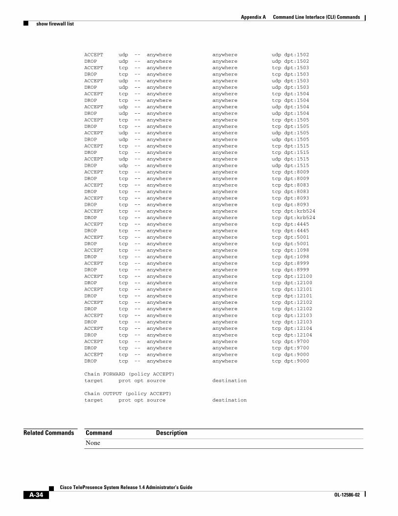
A-34Cisco TelePresence System Release 1.4 Administrator’s Guide
OL-12586-02
Appendix A Command Line Interface (CLI) Commands show firewall list
ACCEPT udp -- anywhere anywhere udp dpt:1502 DROP udp -- anywhere anywhere udp dpt:1502 ACCEPT tcp -- anywhere anywhere tcp dpt:1503 DROP tcp -- anywhere anywhere tcp dpt:1503 ACCEPT udp -- anywhere anywhere udp dpt:1503 DROP udp -- anywhere anywhere udp dpt:1503 ACCEPT tcp -- anywhere anywhere tcp dpt:1504 DROP tcp -- anywhere anywhere tcp dpt:1504 ACCEPT udp -- anywhere anywhere udp dpt:1504 DROP udp -- anywhere anywhere udp dpt:1504 ACCEPT tcp -- anywhere anywhere tcp dpt:1505 DROP tcp -- anywhere anywhere tcp dpt:1505 ACCEPT udp -- anywhere anywhere udp dpt:1505 DROP udp -- anywhere anywhere udp dpt:1505 ACCEPT tcp -- anywhere anywhere tcp dpt:1515 DROP tcp -- anywhere anywhere tcp dpt:1515 ACCEPT udp -- anywhere anywhere udp dpt:1515 DROP udp -- anywhere anywhere udp dpt:1515 ACCEPT tcp -- anywhere anywhere tcp dpt:8009 DROP tcp -- anywhere anywhere tcp dpt:8009 ACCEPT tcp -- anywhere anywhere tcp dpt:8083 DROP tcp -- anywhere anywhere tcp dpt:8083 ACCEPT tcp -- anywhere anywhere tcp dpt:8093 DROP tcp -- anywhere anywhere tcp dpt:8093 ACCEPT tcp -- anywhere anywhere tcp dpt:krb524 DROP tcp -- anywhere anywhere tcp dpt:krb524 ACCEPT tcp -- anywhere anywhere tcp dpt:4445 DROP tcp -- anywhere anywhere tcp dpt:4445 ACCEPT tcp -- anywhere anywhere tcp dpt:5001 DROP tcp -- anywhere anywhere tcp dpt:5001 ACCEPT tcp -- anywhere anywhere tcp dpt:1098 DROP tcp -- anywhere anywhere tcp dpt:1098 ACCEPT tcp -- anywhere anywhere tcp dpt:8999 DROP tcp -- anywhere anywhere tcp dpt:8999 ACCEPT tcp -- anywhere anywhere tcp dpt:12100 DROP tcp -- anywhere anywhere tcp dpt:12100 ACCEPT tcp -- anywhere anywhere tcp dpt:12101 DROP tcp -- anywhere anywhere tcp dpt:12101 ACCEPT tcp -- anywhere anywhere tcp dpt:12102 DROP tcp -- anywhere anywhere tcp dpt:12102 ACCEPT tcp -- anywhere anywhere tcp dpt:12103 DROP tcp -- anywhere anywhere tcp dpt:12103 ACCEPT tcp -- anywhere anywhere tcp dpt:12104 DROP tcp -- anywhere anywhere tcp dpt:12104 ACCEPT tcp -- anywhere anywhere tcp dpt:9700 DROP tcp -- anywhere anywhere tcp dpt:9700 ACCEPT tcp -- anywhere anywhere tcp dpt:9000 DROP tcp -- anywhere anywhere tcp dpt:9000
Chain FORWARD (policy ACCEPT)target prot opt source destination
Chain OUTPUT (policy ACCEPT)target prot opt source destination
Related Commands Command Description
None
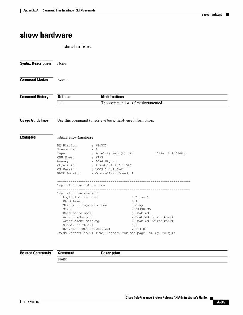
A-35Cisco TelePresence System Release 1.4 Administrator’s Guide
OL-12586-02
Appendix A Command Line Interface (CLI) Commands show hardware
show hardwareshow hardware
Syntax Description None
Command Modes Admin
Command History
Usage Guidelines Use this command to retrieve basic hardware information.
Examples admin:show hardware
HW Platform : 7845I2Processors : 2Type : Intel(R) Xeon(R) CPU 5140 @ 2.33GHzCPU Speed : 2333Memory : 4096 MBytesObject ID : 1.3.6.1.4.1.9.1.587OS Version : UCOS 2.0.1.0-41RAID Details : Controllers found: 1
----------------------------------------------------------------------Logical drive information----------------------------------------------------------------------Logical drive number 1 Logical drive name : Drive 1 RAID level : 1 Status of logical drive : Okay Size : 69890 MB Read-cache mode : Enabled Write-cache mode : Enabled (write-back) Write-cache setting : Enabled (write-back) Number of chunks : 2 Drive(s) (Channel,Device) : 0,0 0,1 Press <enter> for 1 line, <space> for one page, or <q> to quit
Related Commands
Release Modifications
1.1 This command was first documented.
Command Description
None
A-36Cisco TelePresence System Release 1.4 Administrator’s Guide
OL-12586-02
Appendix A Command Line Interface (CLI) Commands show holdresume
show holdresumeshow holdresume
Syntax Description None
Command Modes Admin
Command History
Usage Guidelines Use this command to retrieve current server side hold/resume settings for static and scheduled conferences.
Examples admin:show holdresume server side hold_resume is enabled
Related Commands
Release Modifications
1.1 The command was first documented.
Command Description
set holdresume Enables or disables server side hold/resume feature for static and scheduled conferences
A-37Cisco TelePresence System Release 1.4 Administrator’s Guide
OL-12586-02
Appendix A Command Line Interface (CLI) Commands show lateendmins
show lateendminsshow lateendmins
Syntax Description None
Command Modes Admin
Command History
Usage Guidelines Use this command to show the defined number of minutes after which a conference will be terminated when the meeting exceeds the scheduled end time.
Examples admin:show latenedmins
Related Commands
Release Modifications
1.1 The command was first documented.
Command Description
set lateendmins Defines the number of minutes after which a conference will be terminated when the meeting exceeds the scheduled end time
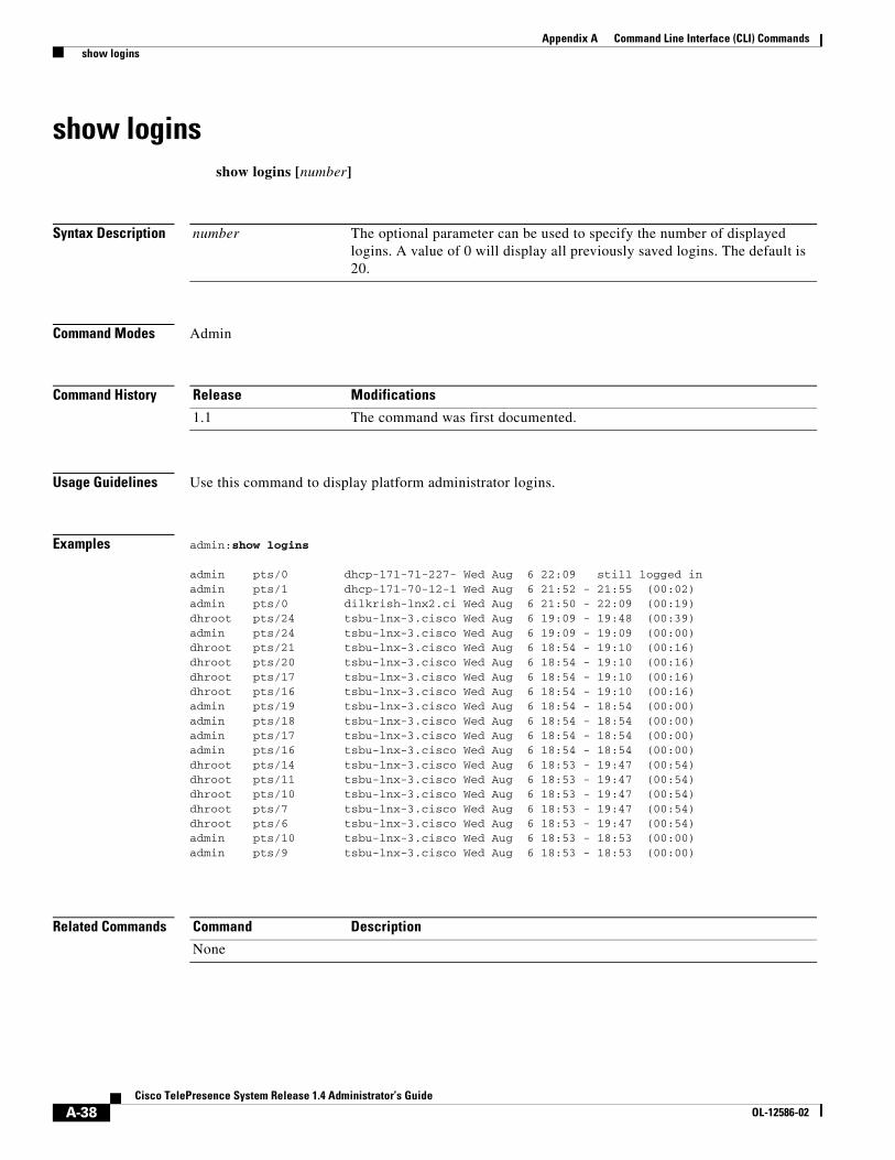
A-38Cisco TelePresence System Release 1.4 Administrator’s Guide
OL-12586-02
Appendix A Command Line Interface (CLI) Commands show logins
show loginsshow logins [number]
Syntax Description
Command Modes Admin
Command History
Usage Guidelines Use this command to display platform administrator logins.
Examples admin:show logins
admin pts/0 dhcp-171-71-227- Wed Aug 6 22:09 still logged in admin pts/1 dhcp-171-70-12-1 Wed Aug 6 21:52 - 21:55 (00:02) admin pts/0 dilkrish-lnx2.ci Wed Aug 6 21:50 - 22:09 (00:19) dhroot pts/24 tsbu-lnx-3.cisco Wed Aug 6 19:09 - 19:48 (00:39) admin pts/24 tsbu-lnx-3.cisco Wed Aug 6 19:09 - 19:09 (00:00) dhroot pts/21 tsbu-lnx-3.cisco Wed Aug 6 18:54 - 19:10 (00:16) dhroot pts/20 tsbu-lnx-3.cisco Wed Aug 6 18:54 - 19:10 (00:16) dhroot pts/17 tsbu-lnx-3.cisco Wed Aug 6 18:54 - 19:10 (00:16) dhroot pts/16 tsbu-lnx-3.cisco Wed Aug 6 18:54 - 19:10 (00:16) admin pts/19 tsbu-lnx-3.cisco Wed Aug 6 18:54 - 18:54 (00:00) admin pts/18 tsbu-lnx-3.cisco Wed Aug 6 18:54 - 18:54 (00:00) admin pts/17 tsbu-lnx-3.cisco Wed Aug 6 18:54 - 18:54 (00:00) admin pts/16 tsbu-lnx-3.cisco Wed Aug 6 18:54 - 18:54 (00:00) dhroot pts/14 tsbu-lnx-3.cisco Wed Aug 6 18:53 - 19:47 (00:54) dhroot pts/11 tsbu-lnx-3.cisco Wed Aug 6 18:53 - 19:47 (00:54) dhroot pts/10 tsbu-lnx-3.cisco Wed Aug 6 18:53 - 19:47 (00:54) dhroot pts/7 tsbu-lnx-3.cisco Wed Aug 6 18:53 - 19:47 (00:54) dhroot pts/6 tsbu-lnx-3.cisco Wed Aug 6 18:53 - 19:47 (00:54) admin pts/10 tsbu-lnx-3.cisco Wed Aug 6 18:53 - 18:53 (00:00) admin pts/9 tsbu-lnx-3.cisco Wed Aug 6 18:53 - 18:53 (00:00)
Related Commands
number The optional parameter can be used to specify the number of displayed logins. A value of 0 will display all previously saved logins. The default is 20.
Release Modifications
1.1 The command was first documented.
Command Description
None
A-39Cisco TelePresence System Release 1.4 Administrator’s Guide
OL-12586-02
Appendix A Command Line Interface (CLI) Commands show myself
show myselfshow myself
Syntax Description None
Command Modes Admin
Command History
Usage Guidelines Use this command to show information about the current account.
Examples admin:show myselfMachine Name : tsbu-sr2account name : adminprivilege level : 4output setting : disabledlogging setting : disabled
Related Commands
Release Modifications
1.1 This command was first documented.
Command Description
None
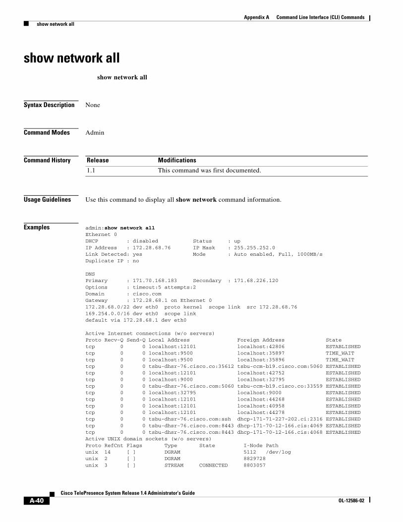
A-40Cisco TelePresence System Release 1.4 Administrator’s Guide
OL-12586-02
Appendix A Command Line Interface (CLI) Commands show network all
show network allshow network all
Syntax Description None
Command Modes Admin
Command History
Usage Guidelines Use this command to display all show network command information.
Examples admin:show network all Ethernet 0DHCP : disabled Status : upIP Address : 172.28.68.76 IP Mask : 255.255.252.0Link Detected: yes Mode : Auto enabled, Full, 1000MB/sDuplicate IP : no
DNSPrimary : 171.70.168.183 Secondary : 171.68.226.120Options : timeout:5 attempts:2Domain : cisco.comGateway : 172.28.68.1 on Ethernet 0172.28.68.0/22 dev eth0 proto kernel scope link src 172.28.68.76 169.254.0.0/16 dev eth0 scope link default via 172.28.68.1 dev eth0
Active Internet connections (w/o servers)Proto Recv-Q Send-Q Local Address Foreign Address State tcp 0 0 localhost:12101 localhost:42806 ESTABLISHED tcp 0 0 localhost:9500 localhost:35897 TIME_WAIT tcp 0 0 localhost:9500 localhost:35896 TIME_WAIT tcp 0 0 tsbu-dhsr-76.cisco.co:35612 tsbu-ccm-b19.cisco.com:5060 ESTABLISHED tcp 0 0 localhost:12101 localhost:42752 ESTABLISHED tcp 0 0 localhost:9000 localhost:32795 ESTABLISHED tcp 0 0 tsbu-dhsr-76.cisco.com:5060 tsbu-ccm-b19.cisco.co:33559 ESTABLISHED tcp 0 0 localhost:32795 localhost:9000 ESTABLISHED tcp 0 0 localhost:12101 localhost:44268 ESTABLISHED tcp 0 0 localhost:12101 localhost:40958 ESTABLISHED tcp 0 0 localhost:12101 localhost:44278 ESTABLISHED tcp 0 0 tsbu-dhsr-76.cisco.com:ssh dhcp-171-71-227-202.ci:2316 ESTABLISHED tcp 0 0 tsbu-dhsr-76.cisco.com:8443 dhcp-171-70-12-166.cis:4069 ESTABLISHED tcp 0 0 tsbu-dhsr-76.cisco.com:8443 dhcp-171-70-12-166.cis:4068 ESTABLISHED Active UNIX domain sockets (w/o servers)Proto RefCnt Flags Type State I-Node Pathunix 14 [ ] DGRAM 5112 /dev/logunix 2 [ ] DGRAM 8829728 unix 3 [ ] STREAM CONNECTED 8803057
Release Modifications
1.1 This command was first documented.
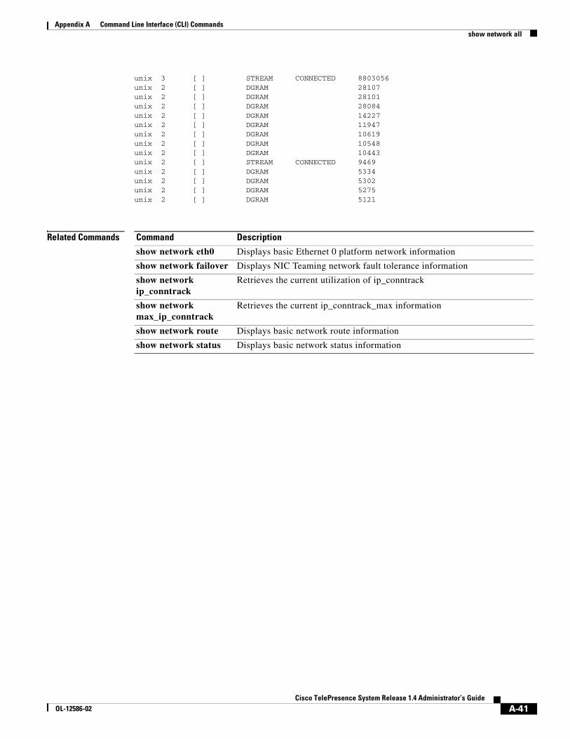
A-41Cisco TelePresence System Release 1.4 Administrator’s Guide
OL-12586-02
Appendix A Command Line Interface (CLI) Commands show network all
unix 3 [ ] STREAM CONNECTED 8803056 unix 2 [ ] DGRAM 28107 unix 2 [ ] DGRAM 28101 unix 2 [ ] DGRAM 28084 unix 2 [ ] DGRAM 14227 unix 2 [ ] DGRAM 11947 unix 2 [ ] DGRAM 10619 unix 2 [ ] DGRAM 10548 unix 2 [ ] DGRAM 10443 unix 2 [ ] STREAM CONNECTED 9469 unix 2 [ ] DGRAM 5334 unix 2 [ ] DGRAM 5302 unix 2 [ ] DGRAM 5275 unix 2 [ ] DGRAM 5121
Related Commands Command Description
show network eth0 Displays basic Ethernet 0 platform network information
show network failover Displays NIC Teaming network fault tolerance information
show network ip_conntrack
Retrieves the current utilization of ip_conntrack
show network max_ip_conntrack
Retrieves the current ip_conntrack_max information
show network route Displays basic network route information
show network status Displays basic network status information
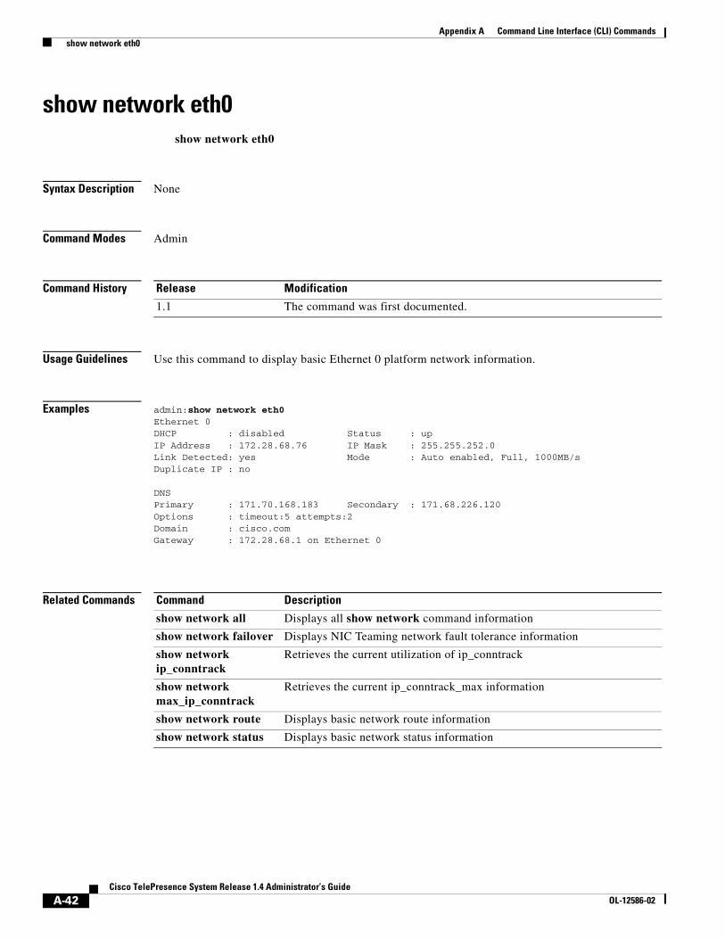
A-42Cisco TelePresence System Release 1.4 Administrator’s Guide
OL-12586-02
Appendix A Command Line Interface (CLI) Commands show network eth0
show network eth0show network eth0
Syntax Description None
Command Modes Admin
Command History
Usage Guidelines Use this command to display basic Ethernet 0 platform network information.
Examples admin:show network eth0 Ethernet 0DHCP : disabled Status : upIP Address : 172.28.68.76 IP Mask : 255.255.252.0Link Detected: yes Mode : Auto enabled, Full, 1000MB/sDuplicate IP : no
DNSPrimary : 171.70.168.183 Secondary : 171.68.226.120Options : timeout:5 attempts:2Domain : cisco.comGateway : 172.28.68.1 on Ethernet 0
Related Commands
Release Modification
1.1 The command was first documented.
Command Description
show network all Displays all show network command information
show network failover Displays NIC Teaming network fault tolerance information
show network ip_conntrack
Retrieves the current utilization of ip_conntrack
show network max_ip_conntrack
Retrieves the current ip_conntrack_max information
show network route Displays basic network route information
show network status Displays basic network status information
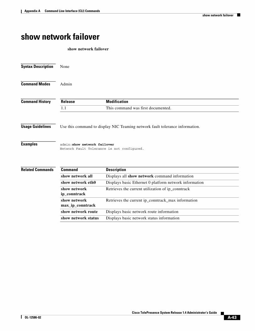
A-43Cisco TelePresence System Release 1.4 Administrator’s Guide
OL-12586-02
Appendix A Command Line Interface (CLI) Commands show network failover
show network failovershow network failover
Syntax Description None
Command Modes Admin
Command History
Usage Guidelines Use this command to display NIC Teaming network fault tolerance information.
Examples admin:show network failover Network Fault Tolerance is not configured.
Related Commands
Release Modification
1.1 This command was first documented.
Command Description
show network all Displays all show network command information
show network eth0 Displays basic Ethernet 0 platform network information
show network ip_conntrack
Retrieves the current utilization of ip_conntrack
show network max_ip_conntrack
Retrieves the current ip_conntrack_max information
show network route Displays basic network route information
show network status Displays basic network status information
A-44Cisco TelePresence System Release 1.4 Administrator’s Guide
OL-12586-02
Appendix A Command Line Interface (CLI) Commands show network ip_conntrack
show network ip_conntrackshow config all [page]
Syntax Description None
Command Modes Admin
Command History
Usage Guidelines Use this command to retrieve the current utilization of ip_conntrack.
Examples admin:show network ip_conntrack
56
Related Commands
Release Modifications
1.1 This command was first documented.
Command Description
show network all Displays all show network command information
show network eth0 Displays basic Ethernet 0 platform network information
show network failover Displays NIC Teaming network fault tolerance information
show network max_ip_conntrack
Retrieves the current ip_conntrack_max information
show network route Displays basic network route information
show network status Displays basic network status information
A-45Cisco TelePresence System Release 1.4 Administrator’s Guide
OL-12586-02
Appendix A Command Line Interface (CLI) Commands show network max_ip_conntrack
show network max_ip_conntrackshow network max_ip_conntrack
Syntax Description None
Command Modes Admin
Command History
Usage Guidelines Use this command to retrieve the current ip_conntrack_max information.
Examples admin:show network max_ip_conntrack
256000
Related Commands
Release Modifications
1.1 This command was first documented.
Command Description
show network all Displays all show network command information
show network eth0 Displays basic Ethernet 0 platform network information
show network failover Displays NIC Teaming network fault tolerance information
show network ip_conntrack
Retrieves the current utilization of ip_conntrack
show network route Displays basic network route information
show network status Displays basic network status information
A-46Cisco TelePresence System Release 1.4 Administrator’s Guide
OL-12586-02
Appendix A Command Line Interface (CLI) Commands show network route
show network routeshow network route
Syntax Description None
Command Modes Admin
Command History
Usage Guidelines Use this command to display basic network route information.
Examples admin:show network route10.94.150.0/24 dev eth0 proto kernel scope link src 10.94.150.94169.254.0.0/16 dev eth0 scope linkdefault via 10.94.150.1 dev eth0
Example with failover (NFT) enabled:
admin:show network route 10.94.150.0/24 dev bond0 proto kernel scope link src 10.94.150.98 10.94.150.0/24 dev eth0 proto kernel scope link src 10.94.150.98 10.94.150.0/24 dev eth1 proto kernel scope link src 10.94.150.98 169.254.0.0/16 dev bond0 scope link default via 10.94.150.1 dev bond0
Related Commands
Release Modifications
1.1 This command was first documented.
Command Description
show network all Displays all show network command information
show network eth0 Displays basic Ethernet 0 platform network information
show network failover Displays NIC Teaming network fault tolerance information
show network ip_conntrack
Retrieves the current utilization of ip_conntrack
show network max_ip_conntrack
Retrieves the current ip_conntrack_max information
show network status Displays basic network status information
A-47Cisco TelePresence System Release 1.4 Administrator’s Guide
OL-12586-02
Appendix A Command Line Interface (CLI) Commands show network status
show network statusshow network status [search name]
Syntax Description
Command Modes Admin
Command History
Usage Guidelines Use this command to retrieve basic network route information.
Examples admin:show network statusActive Internet connections (w/o servers)Proto Recv-Q Send-Q Local Address Foreign Address Statetcp 0 0 vv1-rush.cisco.com:40266 vv1-rush.cisco:vv1_rush_ccm ESTABLISHEDtcp 0 0 localhost:32824 localhost:8001 ESTABLISHED
Example with optional search name:
admin:show network status search cisco.comtcp 0 0 vv1-rush.cisco.com:38775 vv1-rush.cisco:vv1_rush_ccm ESTABLISHEDtcp 0 0 vv1-rush.cisco.com:ssh philly.cisco.com:48528 ESTABLISHEDtcp 0 0 vv1-rush.cisco.com:46993 vv1-rush.cisco.com:32812 TIME_WAIT
Related Commands
search name Optional search feature
name Text string indicating network. String cannot contain spaces or tabs and is case insensitive.
Release Modifications
1.1 This command was first documented.
Command Description
show network all Displays all show network command information
show network eth0 Displays basic Ethernet 0 platform network information
show network failover Displays NIC Teaming network fault tolerance information
show network ip_conntrack
Retrieves the current utilization of ip_conntrack
show network max_ip_conntrack
Retrieves the current ip_conntrack_max information
show network route Displays basic network route information
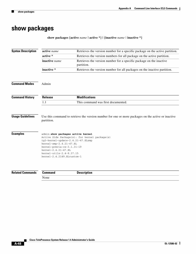
A-48Cisco TelePresence System Release 1.4 Administrator’s Guide
OL-12586-02
Appendix A Command Line Interface (CLI) Commands show packages
show packagesshow packages {active name | active *} | {inactive name | inactive *}
Syntax Description
Command Modes Admin
Command History
Usage Guidelines Use this command to retrieve the version number for one or more packages on the active or inactive partition.
Examples admin:show packages active kernelActive Side Package(s): for kernel package(s)tg3-kernel-update-2.4.21-47.ELsmpkernel-smp-2.4.21-47.ELkernel-pcmcia-cs-3.1.31-19kernel-2.4.21-47.ELkernel-utils-2.4-8.37.15kernel-2.4.2149.ELcustom-1
Related Commands
active name Retrieves the version number for a specific package on the active partition.
active * Retrieves the version numbers for all package on the active partition.
inactive name Retrieves the version number for a specific package on the inactive partition.
inactive * Retrieves the version number for all packages on the inactive partition.
Release Modifications
1.1 This command was first documented.
Command Description
None
A-49Cisco TelePresence System Release 1.4 Administrator’s Guide
OL-12586-02
Appendix A Command Line Interface (CLI) Commands show rtpsleep
show rtpsleepshow rtpsleep
Syntax Description None
Command Modes Admin
Command History
Usage Guidelines Use this command to get current RTP thread sleep time.
Examples admin:show rtpsleep Current RTP thread sleep time is 1 ms
Related Commands
Release Modifications
1.1 This command was first documented.
Command Description
None
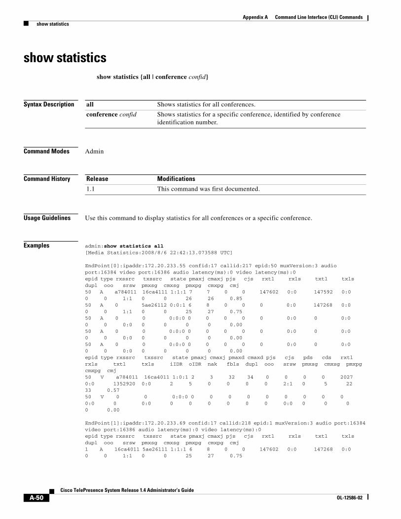
A-50Cisco TelePresence System Release 1.4 Administrator’s Guide
OL-12586-02
Appendix A Command Line Interface (CLI) Commands show statistics
show statisticsshow statistics {all | conference confid}
Syntax Description
Command Modes Admin
Command History
Usage Guidelines Use this command to display statistics for all conferences or a specific conference.
Examples admin:show statistics all[Media Statistics:2008/8/6 22:42:13.073588 UTC]
EndPoint[0]:ipaddr:172.20.233.55 confid:17 callid:217 epid:50 muxVersion:3 audio port:16384 video port:16386 audio latency(ms):0 video latency(ms):0epid type rxssrc txssrc state pmaxj cmaxj pjs cjs rxtl rxls txtl txls dupl ooo srsw pmxsg cmxsg pmxpg cmxpg cmj 50 A a784011 16ca4111 1:1:1 7 7 0 0 147602 0:0 147592 0:0 0 0 1:1 0 0 26 26 0.85 50 A 0 5ae26112 0:0:1 6 8 0 0 0 0:0 147268 0:0 0 0 1:1 0 0 25 27 0.75 50 A 0 0 0:0:0 0 0 0 0 0 0:0 0 0:0 0 0 0:0 0 0 0 0 0.00 50 A 0 0 0:0:0 0 0 0 0 0 0:0 0 0:0 0 0 0:0 0 0 0 0 0.00 50 A 0 0 0:0:0 0 0 0 0 0 0:0 0 0:0 0 0 0:0 0 0 0 0 0.00 epid type rxssrc txssrc state pmaxj cmaxj pmaxd cmaxd pjs cjs pds cds rxtl rxls txtl txls iIDR oIDR nak fbls dupl ooo srsw pmxsg cmxsg pmxpg cmxpg cmj 50 V a784011 16ca4011 1:0:1 2 3 32 34 0 0 0 0 2027 0:0 1352920 0:0 2 5 0 0 0 0 2:1 0 5 22 33 0.57 50 V 0 0 0:0:0 0 0 0 0 0 0 0 0 0 0:0 0 0:0 0 0 0 0 0 0 0:0 0 0 0 0 0.00
EndPoint[1]:ipaddr:172.20.233.69 confid:17 callid:218 epid:1 muxVersion:3 audio port:16384 video port:16386 audio latency(ms):0 video latency(ms):0epid type rxssrc txssrc state pmaxj cmaxj pjs cjs rxtl rxls txtl txls dupl ooo srsw pmxsg cmxsg pmxpg cmxpg cmj 1 A 16ca4011 5ae26111 1:1:1 6 8 0 0 147602 0:0 147268 0:0 0 0 1:1 0 0 25 27 0.75
all Shows statistics for all conferences.
conference confid Shows statistics for a specific conference, identified by conference identification number.
Release Modifications
1.1 This command was first documented.
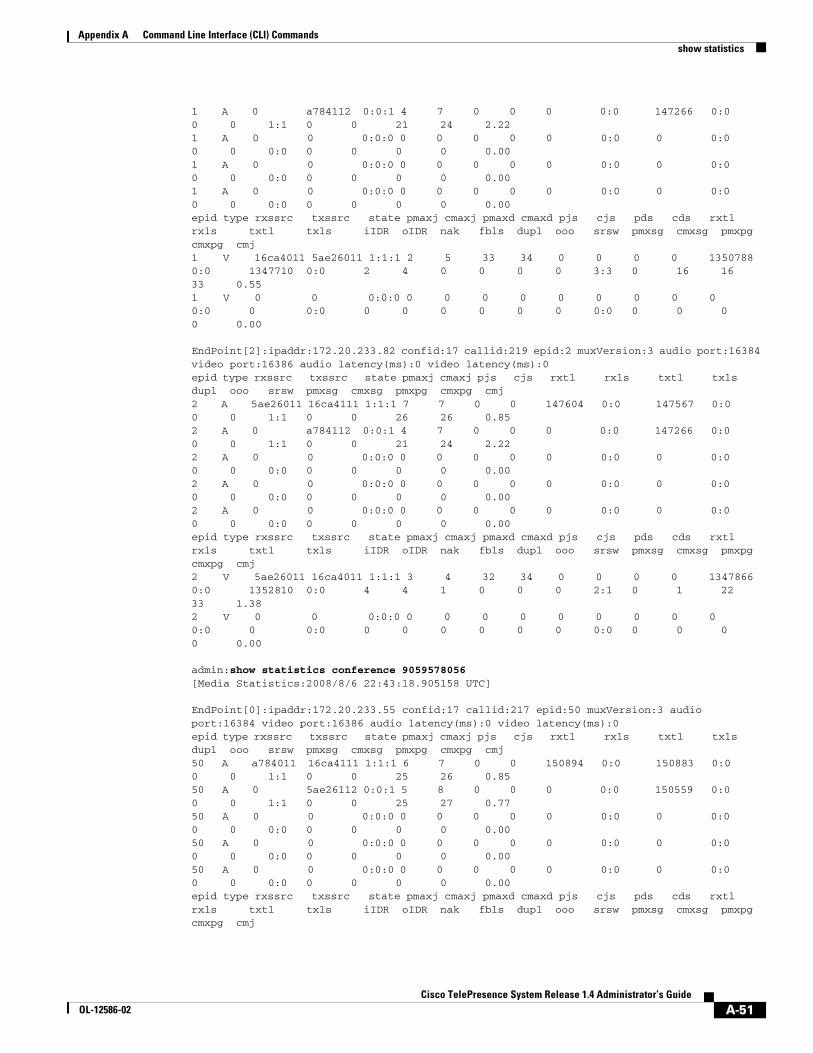
A-51Cisco TelePresence System Release 1.4 Administrator’s Guide
OL-12586-02
Appendix A Command Line Interface (CLI) Commands show statistics
1 A 0 a784112 0:0:1 4 7 0 0 0 0:0 147266 0:0 0 0 1:1 0 0 21 24 2.22 1 A 0 0 0:0:0 0 0 0 0 0 0:0 0 0:0 0 0 0:0 0 0 0 0 0.00 1 A 0 0 0:0:0 0 0 0 0 0 0:0 0 0:0 0 0 0:0 0 0 0 0 0.00 1 A 0 0 0:0:0 0 0 0 0 0 0:0 0 0:0 0 0 0:0 0 0 0 0 0.00 epid type rxssrc txssrc state pmaxj cmaxj pmaxd cmaxd pjs cjs pds cds rxtl rxls txtl txls iIDR oIDR nak fbls dupl ooo srsw pmxsg cmxsg pmxpg cmxpg cmj 1 V 16ca4011 5ae26011 1:1:1 2 5 33 34 0 0 0 0 1350788 0:0 1347710 0:0 2 4 0 0 0 0 3:3 0 16 16 33 0.55 1 V 0 0 0:0:0 0 0 0 0 0 0 0 0 0 0:0 0 0:0 0 0 0 0 0 0 0:0 0 0 0 0 0.00
EndPoint[2]:ipaddr:172.20.233.82 confid:17 callid:219 epid:2 muxVersion:3 audio port:16384 video port:16386 audio latency(ms):0 video latency(ms):0epid type rxssrc txssrc state pmaxj cmaxj pjs cjs rxtl rxls txtl txls dupl ooo srsw pmxsg cmxsg pmxpg cmxpg cmj 2 A 5ae26011 16ca4111 1:1:1 7 7 0 0 147604 0:0 147567 0:0 0 0 1:1 0 0 26 26 0.85 2 A 0 a784112 0:0:1 4 7 0 0 0 0:0 147266 0:0 0 0 1:1 0 0 21 24 2.22 2 A 0 0 0:0:0 0 0 0 0 0 0:0 0 0:0 0 0 0:0 0 0 0 0 0.00 2 A 0 0 0:0:0 0 0 0 0 0 0:0 0 0:0 0 0 0:0 0 0 0 0 0.00 2 A 0 0 0:0:0 0 0 0 0 0 0:0 0 0:0 0 0 0:0 0 0 0 0 0.00 epid type rxssrc txssrc state pmaxj cmaxj pmaxd cmaxd pjs cjs pds cds rxtl rxls txtl txls iIDR oIDR nak fbls dupl ooo srsw pmxsg cmxsg pmxpg cmxpg cmj 2 V 5ae26011 16ca4011 1:1:1 3 4 32 34 0 0 0 0 1347866 0:0 1352810 0:0 4 4 1 0 0 0 2:1 0 1 22 33 1.38 2 V 0 0 0:0:0 0 0 0 0 0 0 0 0 0 0:0 0 0:0 0 0 0 0 0 0 0:0 0 0 0 0 0.00
admin:show statistics conference 9059578056[Media Statistics:2008/8/6 22:43:18.905158 UTC]
EndPoint[0]:ipaddr:172.20.233.55 confid:17 callid:217 epid:50 muxVersion:3 audio port:16384 video port:16386 audio latency(ms):0 video latency(ms):0epid type rxssrc txssrc state pmaxj cmaxj pjs cjs rxtl rxls txtl txls dupl ooo srsw pmxsg cmxsg pmxpg cmxpg cmj 50 A a784011 16ca4111 1:1:1 6 7 0 0 150894 0:0 150883 0:0 0 0 1:1 0 0 25 26 0.85 50 A 0 5ae26112 0:0:1 5 8 0 0 0 0:0 150559 0:0 0 0 1:1 0 0 25 27 0.77 50 A 0 0 0:0:0 0 0 0 0 0 0:0 0 0:0 0 0 0:0 0 0 0 0 0.00 50 A 0 0 0:0:0 0 0 0 0 0 0:0 0 0:0 0 0 0:0 0 0 0 0 0.00 50 A 0 0 0:0:0 0 0 0 0 0 0:0 0 0:0 0 0 0:0 0 0 0 0 0.00 epid type rxssrc txssrc state pmaxj cmaxj pmaxd cmaxd pjs cjs pds cds rxtl rxls txtl txls iIDR oIDR nak fbls dupl ooo srsw pmxsg cmxsg pmxpg cmxpg cmj
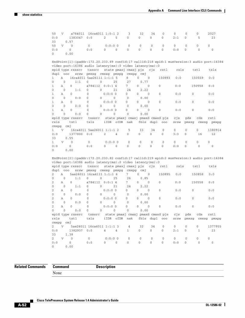
A-52Cisco TelePresence System Release 1.4 Administrator’s Guide
OL-12586-02
Appendix A Command Line Interface (CLI) Commands show statistics
50 V a784011 16ca4011 1:0:1 2 3 32 34 0 0 0 0 2027 0:0 1383047 0:0 2 5 0 0 0 0 2:1 0 5 23 33 0.57 50 V 0 0 0:0:0 0 0 0 0 0 0 0 0 0 0:0 0 0:0 0 0 0 0 0 0 0:0 0 0 0 0 0.00
EndPoint[1]:ipaddr:172.20.233.69 confid:17 callid:218 epid:1 muxVersion:3 audio port:16384 video port:16386 audio latency(ms):0 video latency(ms):0epid type rxssrc txssrc state pmaxj cmaxj pjs cjs rxtl rxls txtl txls dupl ooo srsw pmxsg cmxsg pmxpg cmxpg cmj 1 A 16ca4011 5ae26111 1:1:1 5 8 0 0 150893 0:0 150559 0:0 0 0 1:1 0 0 25 27 0.77 1 A 0 a784112 0:0:1 4 7 0 0 0 0:0 150558 0:0 0 0 1:1 0 0 21 24 2.22 1 A 0 0 0:0:0 0 0 0 0 0 0:0 0 0:0 0 0 0:0 0 0 0 0 0.00 1 A 0 0 0:0:0 0 0 0 0 0 0:0 0 0:0 0 0 0:0 0 0 0 0 0.00 1 A 0 0 0:0:0 0 0 0 0 0 0:0 0 0:0 0 0 0:0 0 0 0 0 0.00 epid type rxssrc txssrc state pmaxj cmaxj pmaxd cmaxd pjs cjs pds cds rxtl rxls txtl txls iIDR oIDR nak fbls dupl ooo srsw pmxsg cmxsg pmxpg cmxpg cmj 1 V 16ca4011 5ae26011 1:1:1 2 5 33 34 0 0 0 0 1380914 0:0 1377800 0:0 2 4 0 0 0 0 3:3 0 16 12 33 0.55 1 V 0 0 0:0:0 0 0 0 0 0 0 0 0 0 0:0 0 0:0 0 0 0 0 0 0 0:0 0 0 0 0 0.00
EndPoint[2]:ipaddr:172.20.233.82 confid:17 callid:219 epid:2 muxVersion:3 audio port:16384 video port:16386 audio latency(ms):0 video latency(ms):0epid type rxssrc txssrc state pmaxj cmaxj pjs cjs rxtl rxls txtl txls dupl ooo srsw pmxsg cmxsg pmxpg cmxpg cmj 2 A 5ae26011 16ca4111 1:1:1 6 7 0 0 150895 0:0 150858 0:0 0 0 1:1 0 0 25 26 0.85 2 A 0 a784112 0:0:1 4 7 0 0 0 0:0 150558 0:0 0 0 1:1 0 0 21 24 2.22 2 A 0 0 0:0:0 0 0 0 0 0 0:0 0 0:0 0 0 0:0 0 0 0 0 0.00 2 A 0 0 0:0:0 0 0 0 0 0 0:0 0 0:0 0 0 0:0 0 0 0 0 0.00 2 A 0 0 0:0:0 0 0 0 0 0 0:0 0 0:0 0 0 0:0 0 0 0 0 0.00 epid type rxssrc txssrc state pmaxj cmaxj pmaxd cmaxd pjs cjs pds cds rxtl rxls txtl txls iIDR oIDR nak fbls dupl ooo srsw pmxsg cmxsg pmxpg cmxpg cmj 2 V 5ae26011 16ca4011 1:1:1 3 4 32 34 0 0 0 0 1377955 0:0 1382937 0:0 4 4 1 0 0 0 2:1 0 1 23 33 1.38 2 V 0 0 0:0:0 0 0 0 0 0 0 0 0 0 0:0 0 0:0 0 0 0 0 0 0 0:0 0 0 0 0 0.00
Related Commands Command Description
None
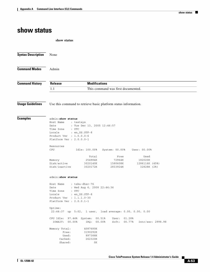
A-53Cisco TelePresence System Release 1.4 Administrator’s Guide
OL-12586-02
Appendix A Command Line Interface (CLI) Commands show status
show statusshow status
Syntax Description None
Command Modes Admin
Command History
Usage Guidelines Use this command to retrieve basic platform status information.
Examples admin:show statusHost Name : testsysDate : Tue Dec 13, 2005 12:46:57Time Zone : UTCLocale : en_US.UTF-8Product Ver : 1.0.0.0-6Platform Ver : 2.0.0.0-1
ResourcesCPU Idle: 100.00% System: 00.00% User: 00.00%
Total Free UsedMemory 254984K 72964K 182020KDisk/active 3020140K 1580608K 1286116K (45%)Disk/inactive 3020172K 2833924K 32828K (2%)
admin:show status
Host Name : tsbu-dhsr-76Date : Wed Aug 6, 2008 22:44:36Time Zone : UTCLocale : en_US.UTF-8Product Ver : 1.1.1.0-30Platform Ver : 2.0.0.1-1
Uptime: 22:44:37 up 5:02, 1 user, load average: 0.00, 0.00, 0.00
CPU Idle: 97.44% System: 00.51% User: 01.28% IOWAIT: 00.00% IRQ: 00.00% Soft: 00.77% Intr/sec: 2998.98
Memory Total: 4087680K Free: 3190292K Used: 897388K Cached: 262320K Shared: 0K
Release Modifications
1.1 This command was first documented.
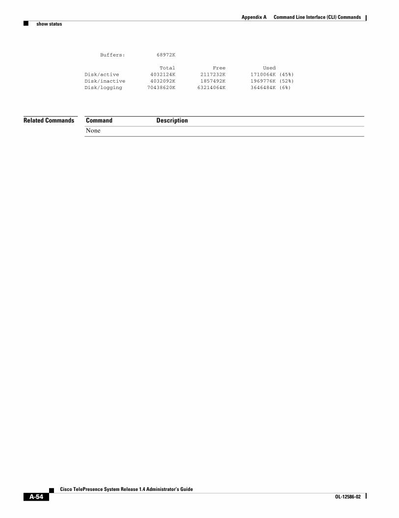
A-54Cisco TelePresence System Release 1.4 Administrator’s Guide
OL-12586-02
Appendix A Command Line Interface (CLI) Commands show status
Buffers: 68972K
Total Free UsedDisk/active 4032124K 2117232K 1710064K (45%)Disk/inactive 4032092K 1857492K 1969776K (52%)Disk/logging 70438620K 63214064K 3646484K (6%)
Related Commands Command Description
None

A-55Cisco TelePresence System Release 1.4 Administrator’s Guide
OL-12586-02
Appendix A Command Line Interface (CLI) Commands show threshold
show thresholdshow threshold
Syntax Description None
Command Modes Admin
Command History
Usage Guidelines Use this command to get current maximum burst packet threshold.
Examples admin: show threshold Current max burst packet threshold is 20
Related Commands
Release Modifications
1.1 This command was first documented.
Command Description
None
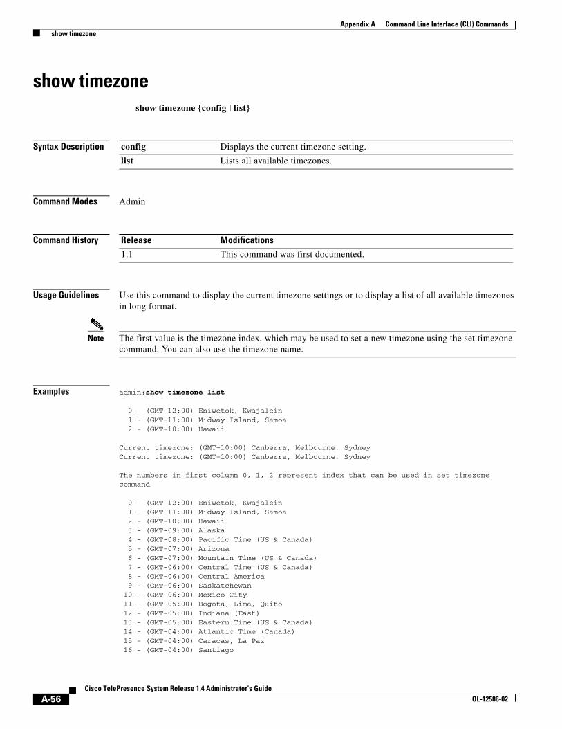
A-56Cisco TelePresence System Release 1.4 Administrator’s Guide
OL-12586-02
Appendix A Command Line Interface (CLI) Commands show timezone
show timezoneshow timezone {config | list}
Syntax Description
Command Modes Admin
Command History
Usage Guidelines Use this command to display the current timezone settings or to display a list of all available timezones in long format.
Note The first value is the timezone index, which may be used to set a new timezone using the set timezone command. You can also use the timezone name.
Examples admin:show timezone list
0 - (GMT-12:00) Eniwetok, Kwajalein 1 - (GMT-11:00) Midway Island, Samoa 2 - (GMT-10:00) Hawaii
Current timezone: (GMT+10:00) Canberra, Melbourne, SydneyCurrent timezone: (GMT+10:00) Canberra, Melbourne, Sydney
The numbers in first column 0, 1, 2 represent index that can be used in set timezone command
0 - (GMT-12:00) Eniwetok, Kwajalein 1 - (GMT-11:00) Midway Island, Samoa 2 - (GMT-10:00) Hawaii 3 - (GMT-09:00) Alaska 4 - (GMT-08:00) Pacific Time (US & Canada) 5 - (GMT-07:00) Arizona 6 - (GMT-07:00) Mountain Time (US & Canada) 7 - (GMT-06:00) Central Time (US & Canada) 8 - (GMT-06:00) Central America 9 - (GMT-06:00) Saskatchewan 10 - (GMT-06:00) Mexico City 11 - (GMT-05:00) Bogota, Lima, Quito 12 - (GMT-05:00) Indiana (East) 13 - (GMT-05:00) Eastern Time (US & Canada) 14 - (GMT-04:00) Atlantic Time (Canada) 15 - (GMT-04:00) Caracas, La Paz 16 - (GMT-04:00) Santiago
config Displays the current timezone setting.
list Lists all available timezones.
Release Modifications
1.1 This command was first documented.
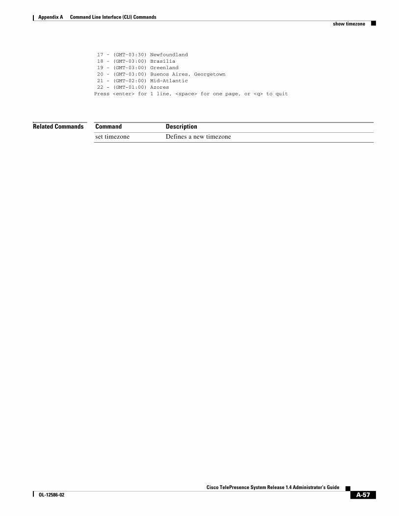
A-57Cisco TelePresence System Release 1.4 Administrator’s Guide
OL-12586-02
Appendix A Command Line Interface (CLI) Commands show timezone
17 - (GMT-03:30) Newfoundland 18 - (GMT-03:00) Brasilia 19 - (GMT-03:00) Greenland 20 - (GMT-03:00) Buenos Aires, Georgetown 21 - (GMT-02:00) Mid-Atlantic 22 - (GMT-01:00) AzoresPress <enter> for 1 line, <space> for one page, or <q> to quit
Related Commands Command Description
set timezone Defines a new timezone
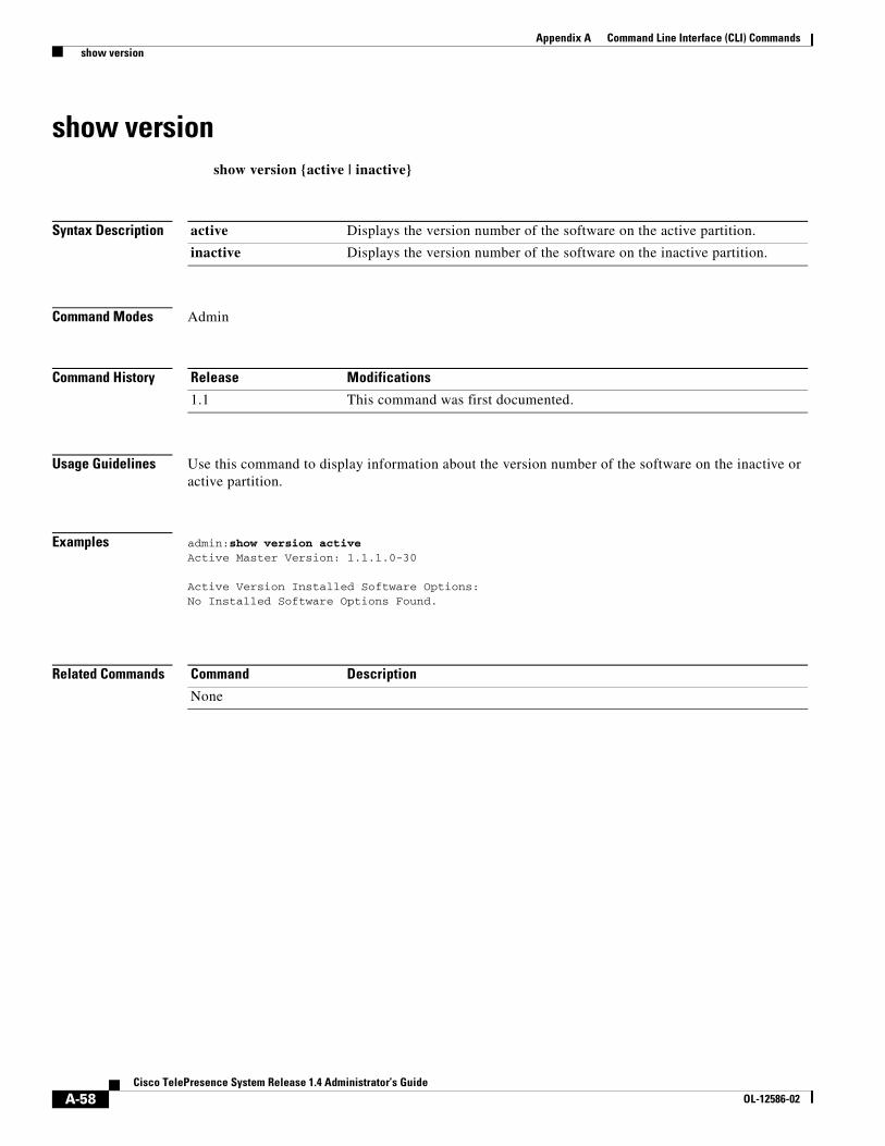
A-58Cisco TelePresence System Release 1.4 Administrator’s Guide
OL-12586-02
Appendix A Command Line Interface (CLI) Commands show version
show versionshow version {active | inactive}
Syntax Description
Command Modes Admin
Command History
Usage Guidelines Use this command to display information about the version number of the software on the inactive or active partition.
Examples admin:show version active Active Master Version: 1.1.1.0-30
Active Version Installed Software Options: No Installed Software Options Found.
Related Commands
active Displays the version number of the software on the active partition.
inactive Displays the version number of the software on the inactive partition.
Release Modifications
1.1 This command was first documented.
Command Description
None
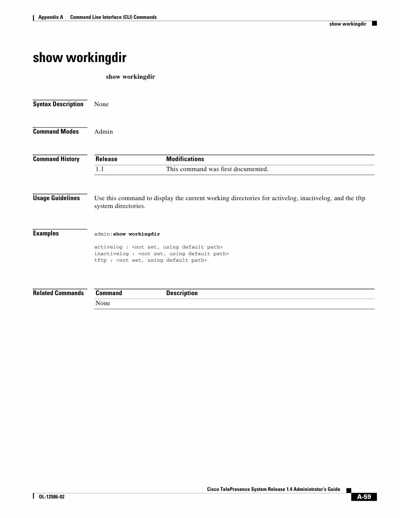
A-59Cisco TelePresence System Release 1.4 Administrator’s Guide
OL-12586-02
Appendix A Command Line Interface (CLI) Commands show workingdir
show workingdirshow workingdir
Syntax Description None
Command Modes Admin
Command History
Usage Guidelines Use this command to display the current working directories for activelog, inactivelog, and the tftp system directories.
Examples admin:show workingdir
activelog : <not set, using default path>inactivelog : <not set, using default path>tftp : <not set, using default path>
Related Commands
Release Modifications
1.1 This command was first documented.
Command Description
None
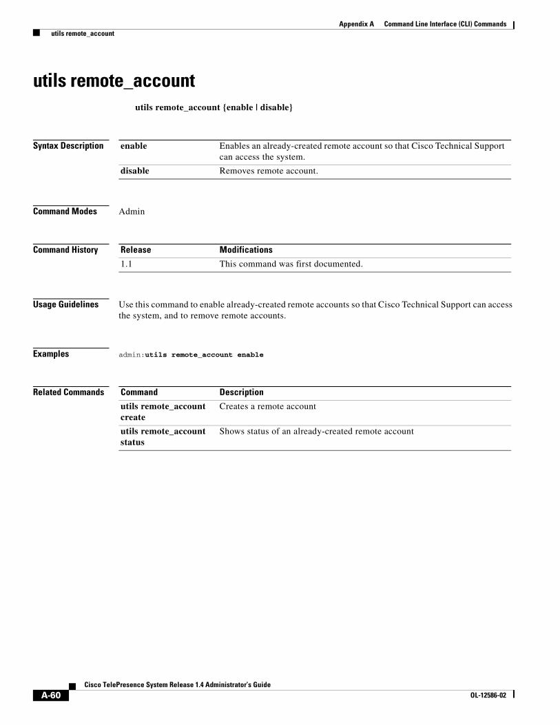
A-60Cisco TelePresence System Release 1.4 Administrator’s Guide
OL-12586-02
Appendix A Command Line Interface (CLI) Commands utils remote_account
utils remote_accountutils remote_account {enable | disable}
Syntax Description
Command Modes Admin
Command History
Usage Guidelines Use this command to enable already-created remote accounts so that Cisco Technical Support can access the system, and to remove remote accounts.
Examples admin:utils remote_account enable
Related Commands
enable Enables an already-created remote account so that Cisco Technical Support can access the system.
disable Removes remote account.
Release Modifications
1.1 This command was first documented.
Command Description
utils remote_account create
Creates a remote account
utils remote_account status
Shows status of an already-created remote account
A-61Cisco TelePresence System Release 1.4 Administrator’s Guide
OL-12586-02
Appendix A Command Line Interface (CLI) Commands utils remote_account create
utils remote_account createutils remote_account create name
Syntax Description
Command Modes Admin
Command History
Usage Guidelines Use this command to create remote accounts so that Cisco Technical Support can access the system.
Examples admin:utils remote_account create ciscotech 1Account Successfully createdAccount : ciscotechPassphrase : 7RZT7ARZK5Expiry : 12-14-2005:15:50:21 (MM-DD-YYYY:Hr:Min:Sec)
Related Commands
name Identifier for remote account
Release Modifications
1.1 This command was first documented.
Command Description
utils remote_account Enables or removes already-created remote accounts
utils remote_account status
Shows status of an already-created remote account

A-62Cisco TelePresence System Release 1.4 Administrator’s Guide
OL-12586-02
Appendix A Command Line Interface (CLI) Commands utils remote_account status
utils remote_account statusutils remote_account status
Syntax Description None
Command Modes Admin
Command History
Usage Guidelines Use this command to retrieve status information for remote accounts used by Cisco Technical Support to access the system.
Examples admin:utils remote_account status Remote SupportStatus : enabledDecode Version : 1Account : dhrootPassphrase : BDLHBP4JMYExpiry : 8-24-2008:20:00:00(MM-DD-YYYY:Hr:Min:Sec)
Related Commands
Release Modifications
1.1 This command was first documented.
Command Description
utils remote_account Enables or removes already-created remote accounts
utils remote_account create
Creates a remote account
A-63Cisco TelePresence System Release 1.4 Administrator’s Guide
OL-12586-02
Appendix A Command Line Interface (CLI) Commands utils system restart
utils system restartutils system restart
Syntax Description None
Command Modes Admin
Command History
Usage Guidelines Use this command to reboot the CTMS.
Examples admin:utils system restartDo you really want to restart ?Enter “yes” to restart or any other key to abort
Related Commands
Release Modifications
1.1 This command was first documented.
Command Description
utils system shutdown Powers off CTMS
utils system switch-version
Switches to another software version installed on CTMS
A-64Cisco TelePresence System Release 1.4 Administrator’s Guide
OL-12586-02
Appendix A Command Line Interface (CLI) Commands utils system shutdown
utils system shutdownutils system shutdown
Syntax Description None
Command Modes Admin
Command History
Usage Guidelines Use this command to power off CTMS.
Examples admin:utils system shutdownDo you really want to shutdown ?Enter “yes” to shutdown or any other key to abort
Related Commands
Release Modifications
1.1 This command was first documented.
Command Description
utils system restart Restarts CTMS
utils system switch-version
Switches to another software version installed on CTMS
A-65Cisco TelePresence System Release 1.4 Administrator’s Guide
OL-12586-02
Appendix A Command Line Interface (CLI) Commands utils system switch-version
utils system switch-versionutils system switch-version
Syntax Description None
Command Modes Admin
Command History
Usage Guidelines Use this command to switch to another software version installed on CTMS.
Examples admin:utils system switch-versionDo you really want to switch versions ?Enter “yes” to switch-version or any other key to abort
Note If any other response is entered, the procedure will be aborted.
Related Commands
Release Modifications
1.1 This command was first documented.
Command Description
utils system restart Restarts CTMS
utils system shutdown Powers off CTMS

A-66Cisco TelePresence System Release 1.4 Administrator’s Guide
OL-12586-02
Appendix A Command Line Interface (CLI) Commands utils system switch-version