cisco tc console v · pdf filethe cisco tc console tool is a visual editor that lets you...
TRANSCRIPT
D14778.02 TC Console version 6 User Guide | © 2013 Cisco Systems, Inc. All rights reserved.
1
Cisco TC Console v.6Customizing layouts and audio ConneCtions for an enhanCed video experienCe
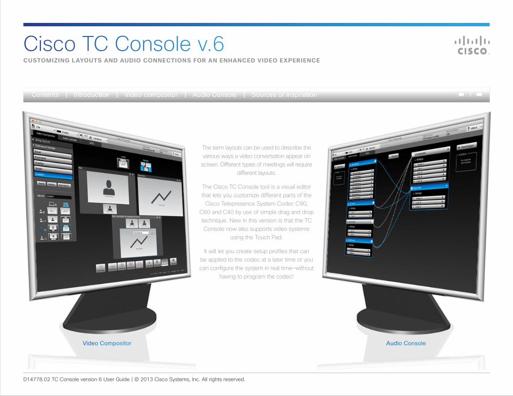
The term layouts can be used to describe the various ways a video conversation appear on screen. Different types of meetings will require
different layouts.
The Cisco TC Console tool is a visual editor that lets you customize different parts of the
Cisco Telepresence System Codec C90, C60 and C40 by use of simple drag and drop technique. New in this version is that the TC Console now also supports video systems
using the Touch Pad.
It will let you create setup profiles that can be applied to the codec at a later time or you can configure the system in real time—without
having to program the codec!
Video Compositor Audio Console
D14778.02 TC Console version 6 User Guide | © 2013 Cisco Systems, Inc. All rights reserved.
2
Cisco TC Console v.6What’s in this user guide?
Cisco TC Console .......................................................... 3Video Compositor .................................................... 3Audio Console ......................................................... 3Starting the TC Console .......................................... 4Defining a new project............................................. 5Synchronizing with the codec.................................. 6Settings must be modified ....................................... 7
The Video Compositor ................................................... 8Base it on existing or create new ............................ 9Layout families ......................................................... 9Video meeting situations ........................................ 9The scenarios .......................................................... 9The layout matrix ................................................... 10Specify your monitor setup.................................... 11Clarify your needs ................................................. 12Edit the layout families ........................................... 13Example................................................................. 14The editing tools available ..................................... 15Using presets to generate layouts ......................... 16Populating the frames ........................................... 17Customizing frames on the stage .......................... 18Specifying exact frame size and position .............. 19Layout families for multiple monitors ..................... 20Presentations for non-dual video streams ............. 21Default layout vs. call scenario ............................... 22
The Audio Console ...................................................... 23Introduction ........................................................... 24Invoking the Audio Console ................................... 24About virtual and physical modules ....................... 25Connecting to a physical source ........................... 25Housekeeping—removing unused sources ............. 25Global settings ....................................................... 26Individual settings .................................................. 26About the equalizer functionality ............................ 27A tour of the equalizer editor ................................. 28Creating a simple peaking filter ............................. 29Adding another peaking filter ................................. 30Using the numerical settings ................................. 31About outputs ........................................................ 32Add and delete connections .................................. 32About the gain setting ........................................... 33Adding an input module......................................... 34Adding an output module ...................................... 35Assign physical outputs to the module .................. 35The Settings .......................................................... 35
General purpose input/output ...................................... 36About GPIO ........................................................... 36
Sources of inspiration .................................................. 37
D14778.02 TC Console version 6 User Guide | © 2013 Cisco Systems, Inc. All rights reserved.
3
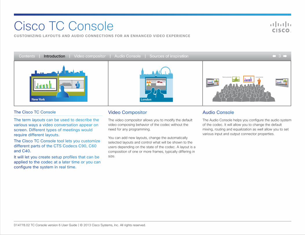
Video CompositorThe video compositor allows you to modify the default video composing behavior of the codec without the need for any programming.
You can add new layouts, change the automatically selected layouts and control what will be shown to the users depending on the state of the codec. A layout is a composition of one or more frames, typically differing in size.
Audio ConsoleThe Audio Console helps you configure the audio system of the codec. It will allow you to change the default mixing, routing and equalization as well allow you to set various input and output connector properties.
The Cisco TC Console
The term layouts can be used to describe the various ways a video conversation appear on screen. Different types of meetings would require different layouts.The Cisco TC Console tool lets you customize different parts of the CTS Codecs C90, C60 and C40. It will let you create setup profiles that can be applied to the codec at a later time or you can configure the system in real time.
Cisco TC ConsoleCustomizing layouts and audio ConneCtions for an enhanCed video experienCe
Local presenterRemote presenter
New York London
Introduction
D14778.02 TC Console version 6 User Guide | © 2013 Cisco Systems, Inc. All rights reserved.
4
TC Consolegetting started
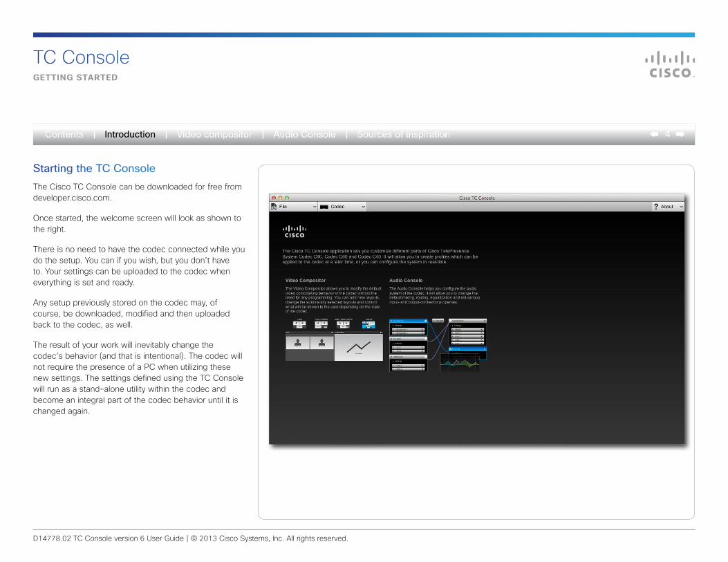
Starting the TC ConsoleThe Cisco TC Console can be downloaded for free from developer.cisco.com.
Once started, the welcome screen will look as shown to the right.
There is no need to have the codec connected while you do the setup. You can if you wish, but you don’t have to. Your settings can be uploaded to the codec when everything is set and ready.
Any setup previously stored on the codec may, of course, be downloaded, modified and then uploaded back to the codec, as well.
The result of your work will inevitably change the codec’s behavior (and that is intentional). The codec will not require the presence of a PC when utilizing these new settings. The settings defined using the TC Console will run as a stand-alone utility within the codec and become an integral part of the codec behavior until it is changed again.
Introduction
D14778.02 TC Console version 6 User Guide | © 2013 Cisco Systems, Inc. All rights reserved.
5
TC ConsoleWorking off-line (no CodeC ConneCted)
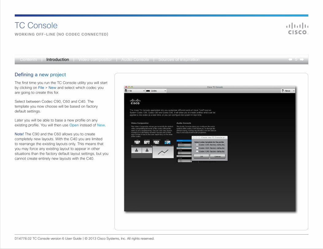
Defining a new projectThe first time you run the TC Console utility you will start by clicking on File > New and select which codec you are going to create this for.
Select between Codec C90, C60 and C40. The template you now choose will be based on factory default settings.
Later you will be able to base a new profile on any existing profile. You will then use Open instead of New.
Note! The C90 and the C60 allows you to create completely new layouts. With the C40 you are limited to rearrange the existing layouts only. This means that you may force any existing layout to appear in other situations than the factory default layout settings, but you cannot create entirely new layouts with the C40.
Introduction
D14778.02 TC Console version 6 User Guide | © 2013 Cisco Systems, Inc. All rights reserved.
6
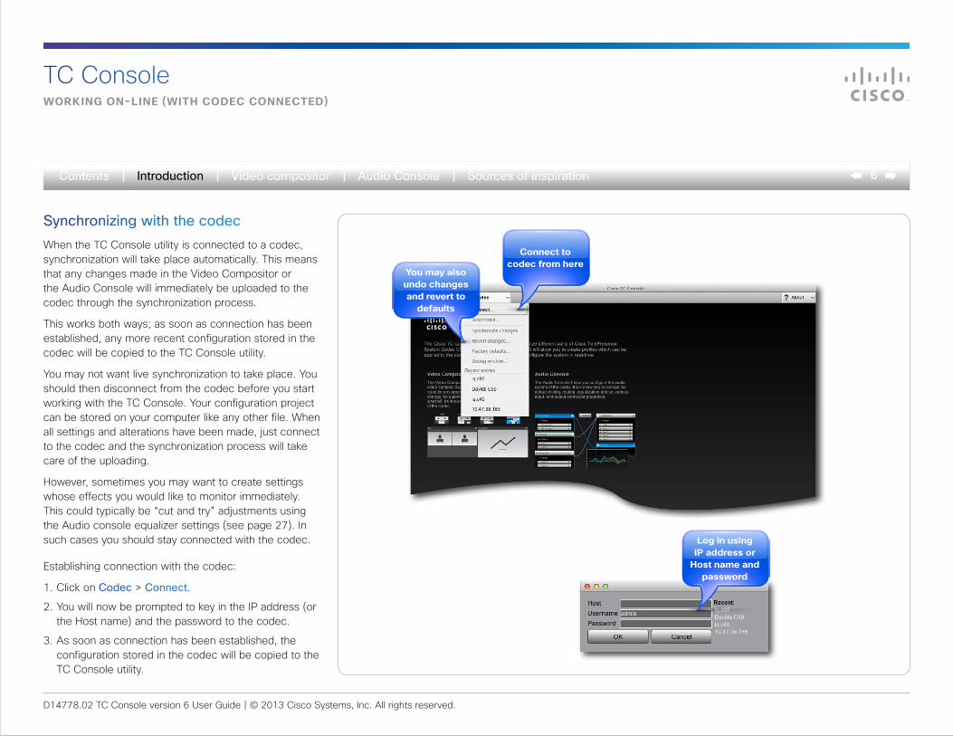
Synchronizing with the codecWhen the TC Console utility is connected to a codec, synchronization will take place automatically. This means that any changes made in the Video Compositor or the Audio Console will immediately be uploaded to the codec through the synchronization process.
This works both ways; as soon as connection has been established, any more recent configuration stored in the codec will be copied to the TC Console utility.
You may not want live synchronization to take place. You should then disconnect from the codec before you start working with the TC Console. Your configuration project can be stored on your computer like any other file. When all settings and alterations have been made, just connect to the codec and the synchronization process will take care of the uploading.
However, sometimes you may want to create settings whose effects you would like to monitor immediately. This could typically be “cut and try” adjustments using the Audio console equalizer settings (see page 27). In such cases you should stay connected with the codec.
Establishing connection with the codec:
1. Click on Codec > Connect.
2. You will now be prompted to key in the IP address (or the Host name) and the password to the codec.
3. As soon as connection has been established, the configuration stored in the codec will be copied to the TC Console utility.
TC ConsoleWorking on-line (With CodeC ConneCted)
Connect to codec from here
you may also undo changes and revert to
defaults
log in using ip address or
host name and password
Introduction
D14778.02 TC Console version 6 User Guide | © 2013 Cisco Systems, Inc. All rights reserved.
7
TC ConsolealloWing the CodeC to make use of your settings
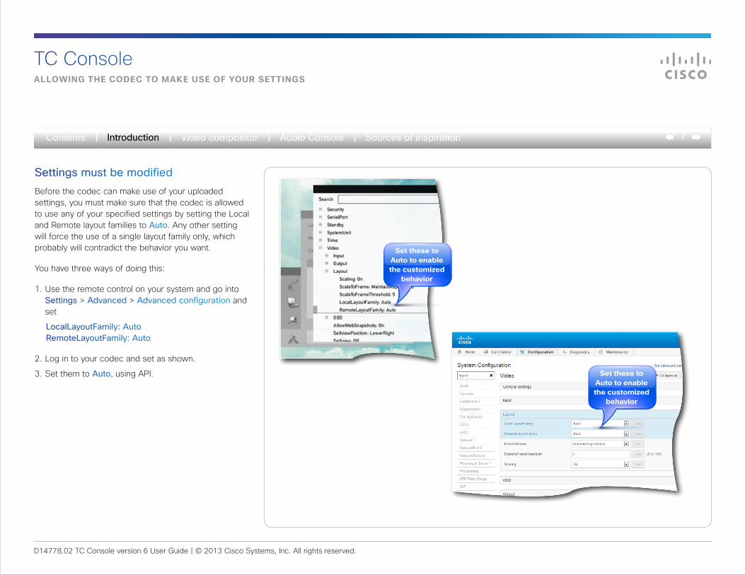
Settings must be modifiedBefore the codec can make use of your uploaded settings, you must make sure that the codec is allowed to use any of your specified settings by setting the Local and Remote layout families to Auto. Any other setting will force the use of a single layout family only, which probably will contradict the behavior you want.
You have three ways of doing this:
1. Use the remote control on your system and go into Settings > Advanced > Advanced configuration and set
LocalLayoutFamily: Auto RemoteLayoutFamily: Auto
2. Log in to your codec and set as shown.
3. Set them to Auto, using API.
set these to auto to enable the customized
behavior
set these to auto to enable the customized
behavior
Introduction
D14778.02 TC Console version 6 User Guide | © 2013 Cisco Systems, Inc. All rights reserved.
8Video compositor
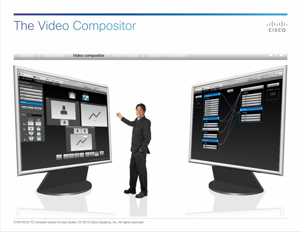
The Video Compositor
D14778.02 TC Console version 6 User Guide | © 2013 Cisco Systems, Inc. All rights reserved.
9Video compositor
Video Compositorthe ConCept
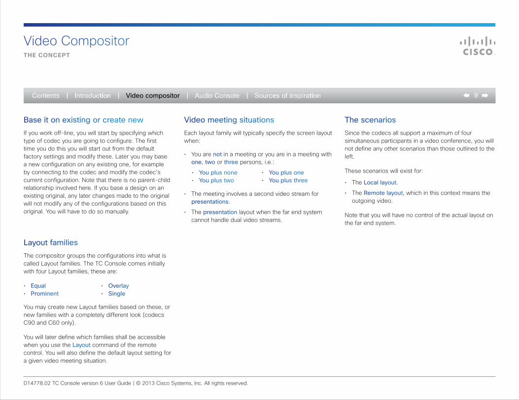
Base it on existing or create newIf you work off-line, you will start by specifying which type of codec you are going to configure. The first time you do this you will start out from the default factory settings and modify these. Later you may base a new configuration on any existing one, for example by connecting to the codec and modify the codec’s current configuration. Note that there is no parent-child relationship involved here. If you base a design on an existing original, any later changes made to the original will not modify any of the configurations based on this original. You will have to do so manually.
Layout familiesThe compositor groups the configurations into what is called Layout families. The TC Console comes initially with four Layout families, these are:
• Equal• Prominent
• Overlay• Single
You may create new Layout families based on these, or new families with a completely different look (codecs C90 and C60 only).
You will later define which families shall be accessible when you use the Layout command of the remote control. You will also define the default layout setting for a given video meeting situation.
Video meeting situations Each layout family will typically specify the screen layout when:
• You are not in a meeting or you are in a meeting with one, two or three persons, i.e.:
• You plus none• You plus two
• You plus one• You plus three
• The meeting involves a second video stream for presentations.
• The presentation layout when the far end system cannot handle dual video streams.
The scenariosSince the codecs all support a maximum of four simultaneous participants in a video conference, you will not define any other scenarios than those outlined to the left.
These scenarios will exist for:
• The Local layout.
• The Remote layout, which in this context means the outgoing video.
Note that you will have no control of the actual layout on the far end system.
D14778.02 TC Console version 6 User Guide | © 2013 Cisco Systems, Inc. All rights reserved.
10Video compositor
Video Compositorthe ConCept
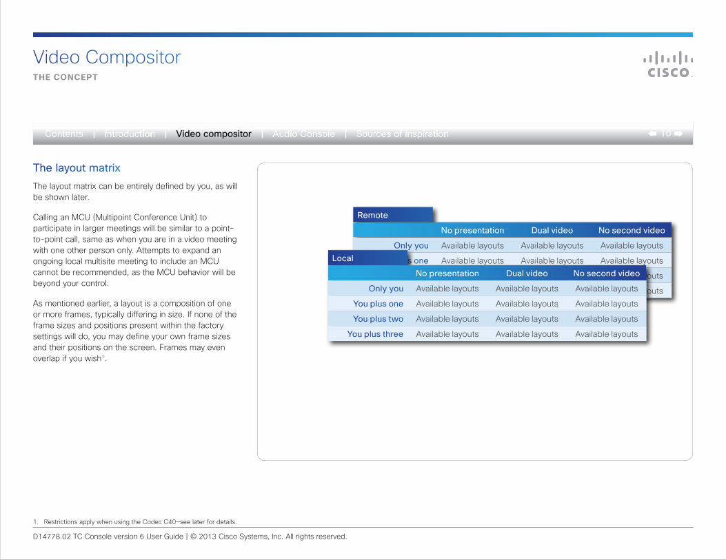
The layout matrixThe layout matrix can be entirely defined by you, as will be shown later.
Calling an MCU (Multipoint Conference Unit) to participate in larger meetings will be similar to a point-to-point call, same as when you are in a video meeting with one other person only. Attempts to expand an ongoing local multisite meeting to include an MCU cannot be recommended, as the MCU behavior will be beyond your control.
As mentioned earlier, a layout is a composition of one or more frames, typically differing in size. If none of the frame sizes and positions present within the factory settings will do, you may define your own frame sizes and their positions on the screen. Frames may even overlap if you wish1.
Remote
No presentation Dual video No second video
Only you Available layouts Available layouts Available layouts
You plus one Available layouts Available layouts Available layouts
You plus two Available layouts Available layouts Available layouts
You plus three Available layouts Available layouts Available layouts
Local
No presentation Dual video No second video
Only you Available layouts Available layouts Available layouts
You plus one Available layouts Available layouts Available layouts
You plus two Available layouts Available layouts Available layouts
You plus three Available layouts Available layouts Available layouts
1. Restrictions apply when using the Codec C40—see later for details.
D14778.02 TC Console version 6 User Guide | © 2013 Cisco Systems, Inc. All rights reserved.
11Video compositor
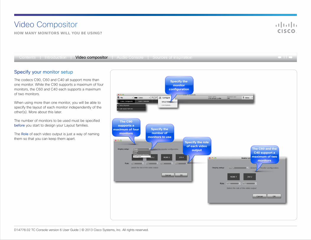
specify the number of
monitors to use
specify the role of each video
output
Specify your monitor setupThe codecs C90, C60 and C40 all support more than one monitor. While the C90 supports a maximum of four monitors, the C60 and C40 each supports a maximum of two monitors.
When using more than one monitor, you will be able to specify the layout of each monitor independently of the other(s). More about this later.
The number of monitors to be used must be specified before you start to design your Layout families.
The Role of each video output is just a way of naming them so that you can keep them apart.
the C60 and the C40 support a
maximum of two monitors
the C90 supports a
maximum of four monitors
Video CompositorhoW many monitors Will you be using?
specify the monitor
configuration
D14778.02 TC Console version 6 User Guide | © 2013 Cisco Systems, Inc. All rights reserved.
12Video compositor
Video CompositorWhere are you heading?
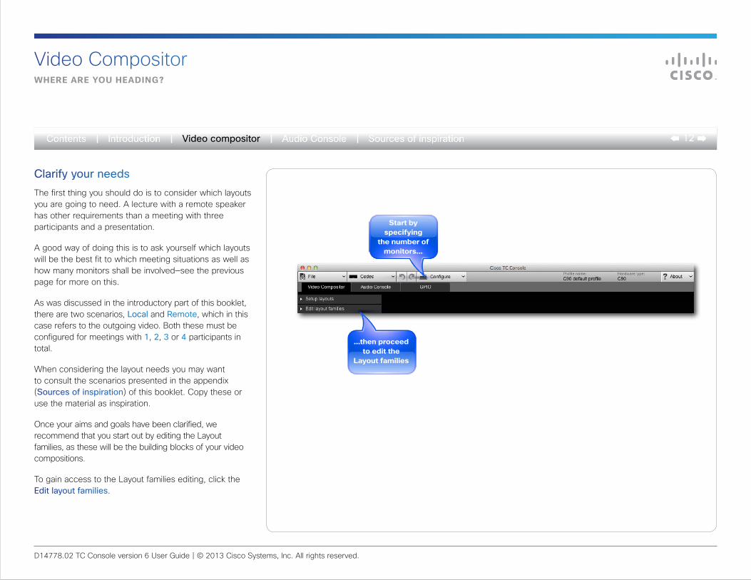
Clarify your needsThe first thing you should do is to consider which layouts you are going to need. A lecture with a remote speaker has other requirements than a meeting with three participants and a presentation.
A good way of doing this is to ask yourself which layouts will be the best fit to which meeting situations as well as how many monitors shall be involved—see the previous page for more on this.
As was discussed in the introductory part of this booklet, there are two scenarios, Local and Remote, which in this case refers to the outgoing video. Both these must be configured for meetings with 1, 2, 3 or 4 participants in total.
When considering the layout needs you may want to consult the scenarios presented in the appendix (Sources of inspiration) of this booklet. Copy these or use the material as inspiration.
Once your aims and goals have been clarified, we recommend that you start out by editing the Layout families, as these will be the building blocks of your video compositions.
To gain access to the Layout families editing, click the Edit layout families.
start by specifying
the number of monitors...
...then proceed to edit the
layout families
D14778.02 TC Console version 6 User Guide | © 2013 Cisco Systems, Inc. All rights reserved.
13Video compositor
Video Compositorstart Creating your oWn layouts
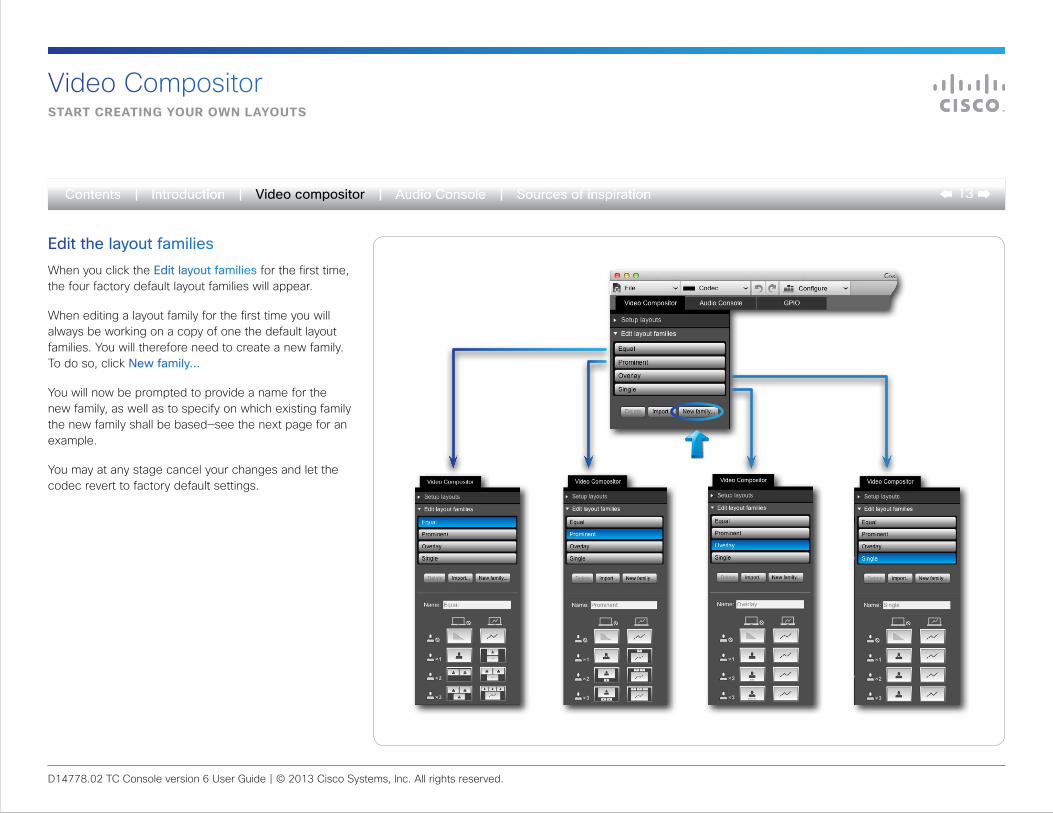
Edit the layout familiesWhen you click the Edit layout families for the first time, the four factory default layout families will appear.
When editing a layout family for the first time you will always be working on a copy of one the default layout families. You will therefore need to create a new family. To do so, click New family...
You will now be prompted to provide a name for the new family, as well as to specify on which existing family the new family shall be based—see the next page for an example.
You may at any stage cancel your changes and let the codec revert to factory default settings.
D14778.02 TC Console version 6 User Guide | © 2013 Cisco Systems, Inc. All rights reserved.
14Video compositor
modifying layouts
Video compositor
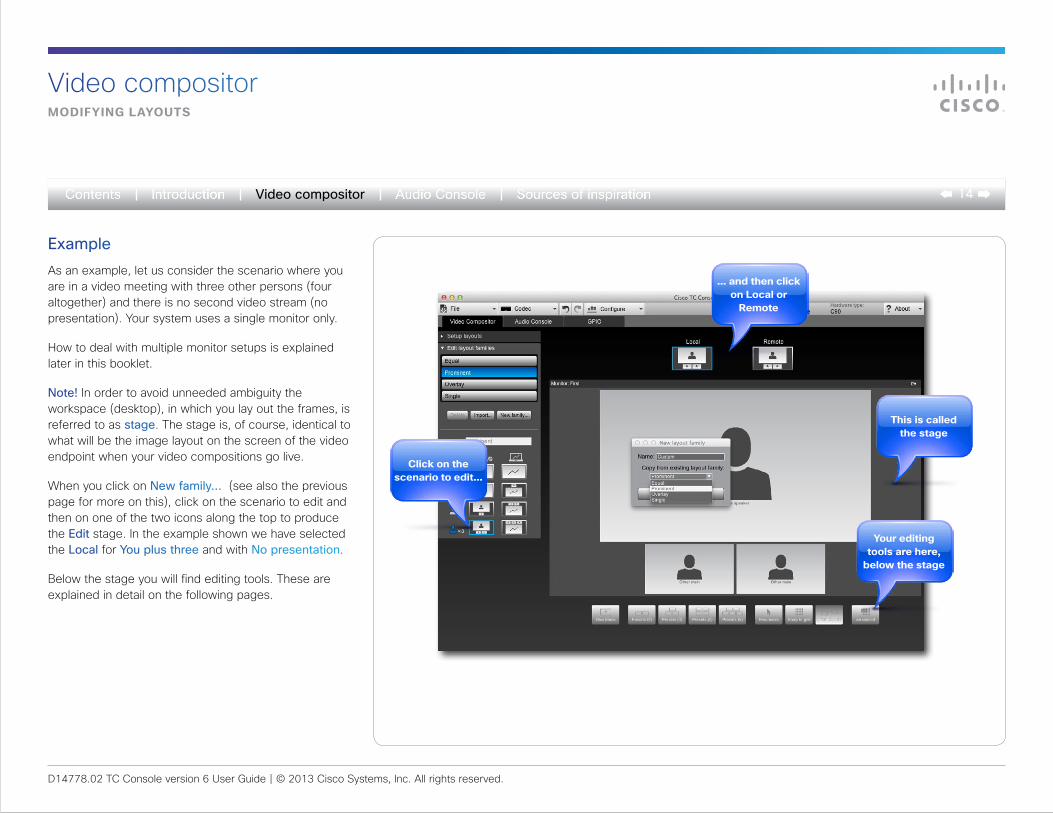
ExampleAs an example, let us consider the scenario where you are in a video meeting with three other persons (four altogether) and there is no second video stream (no presentation). Your system uses a single monitor only.
How to deal with multiple monitor setups is explained later in this booklet.
Note! In order to avoid unneeded ambiguity the workspace (desktop), in which you lay out the frames, is referred to as stage. The stage is, of course, identical to what will be the image layout on the screen of the video endpoint when your video compositions go live.
When you click on New family... (see also the previous page for more on this), click on the scenario to edit and then on one of the two icons along the top to produce the Edit stage. In the example shown we have selected the Local for You plus three and with No presentation.
Below the stage you will find editing tools. These are explained in detail on the following pages.
Click on the scenario to edit...
... and then click on local or
remote
this is called the stage
your editing tools are here,
below the stage
D14778.02 TC Console version 6 User Guide | © 2013 Cisco Systems, Inc. All rights reserved.
15Video compositor
a quiCk look at the toolbox
Video compositor
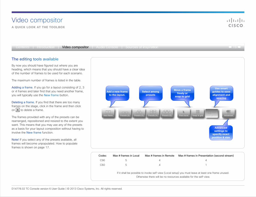
The editing tools availableBy now you should have figured out where you are heading, which means that you should have a clear idea of the number of frames to be used for each scenario.
The maximum number of frames is listed in the table.
Adding a frame. If you go for a layout consisting of 2, 3 or 4 frames and later find that you need another frame, you will typically use the New frame button.
Deleting a frame. If you find that there are too many frames on the stage, click in the frame and then click on to delete a frame.
The frames provided with any of the presets can be rearranged, repositioned and resized to the extent you want. This means that you may use any of the presets as a basis for your layout composition without having to involve the New frame function.
Note! If you select any of the presets available, all frames will become unpopulated. How to populate frames is shown on page 17.
select among presets
add a new frame to the layout.
move a frame freely or
snap to grid
use smart guides to ease alignment and
spacing
advanced settings to
specify exact position & size
If it shall be possible to invoke self-view (Local setup) you must leave at least one frame unused. Otherwise there will be no resources available for the self-view.
Codec Max # frames in Local Max # frames in Remote Max # frames in Presentation (second stream)
C90 5 4 4
C60 5 4 1
D14778.02 TC Console version 6 User Guide | © 2013 Cisco Systems, Inc. All rights reserved.
16Video compositor
advanCed tools
Video compositor
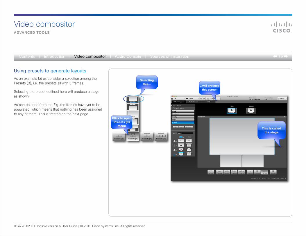
Using presets to generate layoutsAs an example let us consider a selection among the Presets (3), i.e. the presets all with 3 frames.
Selecting the preset outlined here will produce a stage as shown.
As can be seen from the Fig. the frames have yet to be populated, which means that nothing has been assigned to any of them. This is treated on the next page.
Click to open presets (3)
menu
selecting this... ...will produce
this screen
this is called the stage
D14778.02 TC Console version 6 User Guide | © 2013 Cisco Systems, Inc. All rights reserved.
17Video compositor
Video compositordeCiding What to put Where
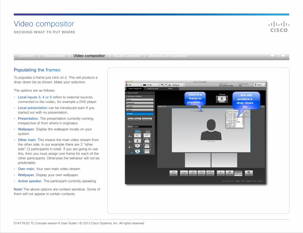
Populating the framesTo populate a frame just click on it. This will produce a drop-down list as shown. Make your selection.
The options are as follows:
• Local inputs 3, 4 or 5 refers to external sources connected to the codec, for example a DVD player.
• Local presentation can be introduced even if you started out with no presentation.
• Presentation. The presentation currently running, irrespective of from where it originates.
• Wallpaper. Display the wallpaper locally on your system.
• Other main. This means the main video stream from the other side. In our example there are 2 “other side” (3 participants in total). If you are going to use this, then you must assign one frame for each of the other participants. Otherwise the behavior will not be predictable.
• Own main. Your own main video stream.
• Wallpaper. Display your own wallpaper.
• Active speaker. The participant currently speaking.
Note! The above options are context sensitive. Some of them will not appear in certain contexts.
Click in a frame to
populate...
...this will produce a
drop-down list
D14778.02 TC Console version 6 User Guide | © 2013 Cisco Systems, Inc. All rights reserved.
18Video compositor
user Controlled design
Video compositor
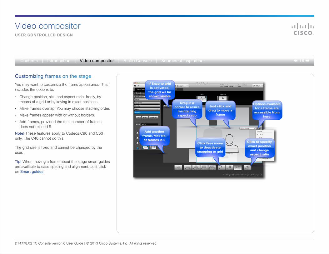
Customizing frames on the stageYou may want to customize the frame appearance. This includes the options to:
• Change position, size and aspect ratio, freely, by means of a grid or by keying in exact positions.
• Make frames overlap. You may choose stacking order.
• Make frames appear with or without borders.
• Add frames, provided the total number of frames does not exceed 5.
Note! These features apply to Codecs C90 and C60 only. The C40 cannot do this.
The grid size is fixed and cannot be changed by the user.
Tip! When moving a frame about the stage smart guides are available to ease spacing and alignment. Just click on Smart guides.
Just click and drag to move a
frame
if snap to grid is activated,
the grid wil be shown visible
Click free move to deactivate
snapping to grid
add another frame. max no. of frames is 5
drag in a corner to resize
maintaining aspect ratio
Click to specify exact position
and change aspect ratio
options available for a frame are
accessible from here
D14778.02 TC Console version 6 User Guide | © 2013 Cisco Systems, Inc. All rights reserved.
19Video compositor
position aCCuraCy
Video compositor
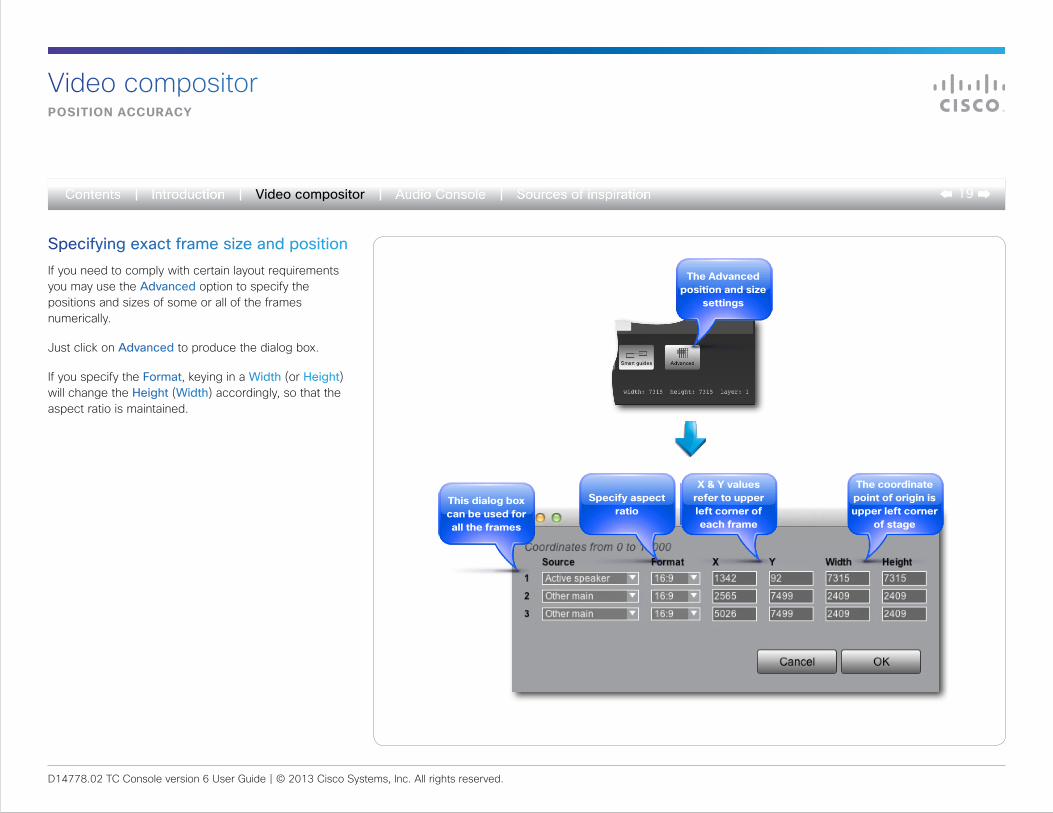
Specifying exact frame size and positionIf you need to comply with certain layout requirements you may use the Advanced option to specify the positions and sizes of some or all of the frames numerically.
Just click on Advanced to produce the dialog box.
If you specify the Format, keying in a Width (or Height)will change the Height (Width) accordingly, so that the aspect ratio is maintained.
the advanced position and size
settings
the coordinate point of origin is upper left corner
of stage
x & y values refer to upper left corner of each frame
this dialog box can be used for all the frames
specify aspect ratio
D14778.02 TC Console version 6 User Guide | © 2013 Cisco Systems, Inc. All rights reserved.
20Video compositor
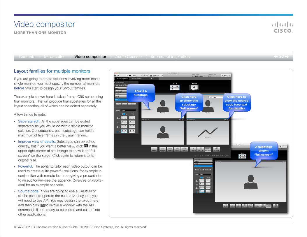
Layout families for multiple monitorsIf you are going to create solutions involving more than a single monitor, you must specify the number of monitors before you start to design your Layout families.
The example shown here is taken from a C90 setup using four monitors. This will produce four substages for all the layout scenarios, all of which can be edited separately.
A few things to note:
• Separate edit. All the substages can be edited separately as you would do with a single monitor solution. Consequently, each substage can hold a maximum of five frames in the usual manner.
• Improve view of details. Substages can be edited directly, but if you want a better view, click in the upper right corner of a substage to show it as “full screen” on the stage. Click again to return it to its original size.
• Powerful. The ability to tailor each video output can be used to create quite powerful solutions, for example in conjunction with remote lecturers giving a presentation to an auditorium—see the appendix (Sources of inspira-tion) for an example scenario.
• Source code. If you are going to use a Crestron or similar panel to operate the customized layouts, you will need to use API. You may design the layout here and then click to invoke a window with the API commands listed, ready to be copied and pasted into other applications.
this is a substage
a substage shown
“full screen”
Click here to show this
substage “full screen”
Click here to view the source code (see text
for details)
Video compositormore than one monitor
D14778.02 TC Console version 6 User Guide | © 2013 Cisco Systems, Inc. All rights reserved.
21Video compositor
Video compositorif the other end Cannot handle dual video streams
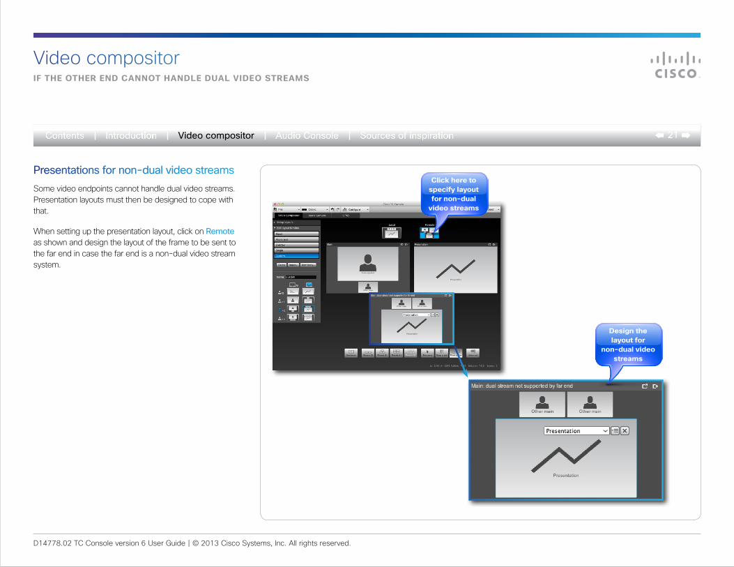
Presentations for non-dual video streamsSome video endpoints cannot handle dual video streams. Presentation layouts must then be designed to cope with that.
When setting up the presentation layout, click on Remote as shown and design the layout of the frame to be sent to the far end in case the far end is a non-dual video stream system.
Click here to specify layout for non-dual
video streams
design the layout for
non-dual video streams
D14778.02 TC Console version 6 User Guide | © 2013 Cisco Systems, Inc. All rights reserved.
22Video compositor
defining the initial user experienCe
Video compositor
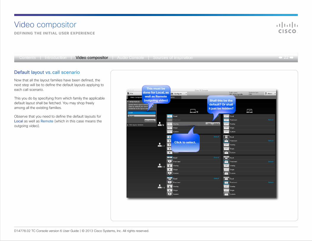
Default layout vs. call scenarioNow that all the layout families have been defined, the next step will be to define the default layouts applying to each call scenario.
This you do by specifying from which family the applicable default layout shall be fetched. You may shop freely among all the existing families.
Observe that you need to define the default layouts for Local as well as Remote (which in this case means the outgoing video).
this must be done for local, as
well as remote (outgoing video) shall this be the
default? or shall it just be hidden?
Click to select.
D14778.02 TC Console version 6 User Guide | © 2013 Cisco Systems, Inc. All rights reserved.
23Audio Console
The Audio Console
D14778.02 TC Console version 6 User Guide | © 2013 Cisco Systems, Inc. All rights reserved.
24Audio Console
an overvieW
The Audio Console
add another input
in this column you will find
inputs currently defined
deactivate an input . this puts sources in the inactive pool
deactivate an output . this puts
sources in the inactive pool
specify gain or attenuation
in this column you will find
outputs currently defined
add another output
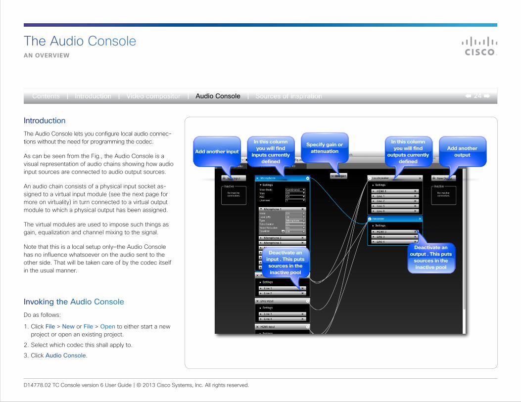
IntroductionThe Audio Console lets you configure local audio connec-tions without the need for programming the codec.
As can be seen from the Fig., the Audio Console is a visual representation of audio chains showing how audio input sources are connected to audio output sources.
An audio chain consists of a physical input socket as-signed to a virtual input module (see the next page for more on virtuality) in turn connected to a virtual output module to which a physical output has been assigned.
The virtual modules are used to impose such things as gain, equalization and channel mixing to the signal.
Note that this is a local setup only—the Audio Console has no influence whatsoever on the audio sent to the other side. That will be taken care of by the codec itself in the usual manner.
Invoking the Audio ConsoleDo as follows:
1. Click File > New or File > Open to either start a new project or open an existing project.
2. Select which codec this shall apply to.
3. Click Audio Console.
D14778.02 TC Console version 6 User Guide | © 2013 Cisco Systems, Inc. All rights reserved.
25Audio Console
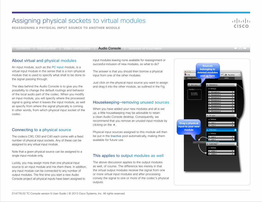
About virtual and physical modulesAn input module, such as the PC input module, is a virtual input module in the sense that is a non-physical module that is used to specify what shall to be done to the signal passing through.
The idea behind the Audio Console is to give you the possibility to change the default routings and behavior of the local audio part of the codec. When you modify an input module, you will specify where the processed signal is going when it leaves the input module, as well as specify from where the signal physically is coming. In other words, from which physical input socket of the codec.
Connecting to a physical sourceThe codecs C90, C60 and C40 each come with a fixed number of physical input sockets. Any of these can be assigned to any virtual input module.
Note that a given physical source can be assigned to a single input module only.
Luckily, you may assign more than one physical input source to an input module and mix them there. In addition, any input module can be connected to any number of output modules. The first time you start a new Audio Console project all physical inputs have been assigned to
reassigning a physiCal input sourCe to another module
Assigning physical sockets to virtual modules
drag a physical input to your new
module
sources belonging to
deleted modules end up here
input modules leaving none available for reassignment or succesful inclusion of new modules, so what to do?
The answer is that you should then borrow a physical input from one of the other modules.
Just click on the physical input source you want to assign and drag it into the other module, as outlined in the Fig.
Housekeeping—removing unused sourcesWhen you have added your new modules and all is set up, a little housekeeping may be advisable to retain a clean Audio Console desktop. Consequently, we recommend that you remove an unused input module by clicking on the ×.
Physical input sources assigned to this module will then be put in the Inactive pool automatically, making them available for future use.
This applies to output modules as wellThe above discussion applies to the output modules as well, of course. The difference lies merely in that the virtual output modules receive the signal from one or more virtual input modules and after processing convey the signal to one or more of the codec’s physical outputs.
D14778.02 TC Console version 6 User Guide | © 2013 Cisco Systems, Inc. All rights reserved.
26Audio Console
using miCrophone input module as an example
Modifying existing modules
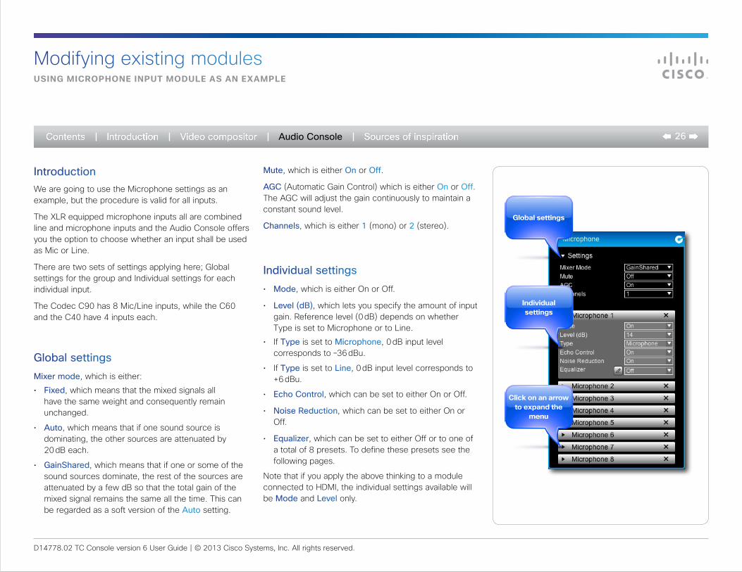
IntroductionWe are going to use the Microphone settings as an example, but the procedure is valid for all inputs.
The XLR equipped microphone inputs all are combined line and microphone inputs and the Audio Console offers you the option to choose whether an input shall be used as Mic or Line.
There are two sets of settings applying here; Global settings for the group and Individual settings for each individual input.
The Codec C90 has 8 Mic/Line inputs, while the C60 and the C40 have 4 inputs each.
Global settingsMixer mode, which is either:
• Fixed, which means that the mixed signals all have the same weight and consequently remain unchanged.
• Auto, which means that if one sound source is dominating, the other sources are attenuated by 20 dB each.
• GainShared, which means that if one or some of the sound sources dominate, the rest of the sources are attenuated by a few dB so that the total gain of the mixed signal remains the same all the time. This can be regarded as a soft version of the Auto setting.
Mute, which is either On or Off.
AGC (Automatic Gain Control) which is either On or Off. The AGC will adjust the gain continuously to maintain a constant sound level.
Channels, which is either 1 (mono) or 2 (stereo).
Individual settings• Mode, which is either On or Off.
• Level (dB), which lets you specify the amount of input gain. Reference level (0 dB) depends on whether Type is set to Microphone or to Line.
• If Type is set to Microphone, 0 dB input level corresponds to –36 dBu.
• If Type is set to Line, 0 dB input level corresponds to +6 dBu.
• Echo Control, which can be set to either On or Off.
• Noise Reduction, which can be set to either On or Off.
• Equalizer, which can be set to either Off or to one of a total of 8 presets. To define these presets see the following pages.
Note that if you apply the above thinking to a module connected to HDMI, the individual settings available will be Mode and Level only.
global settings
individual settings
Click on an arrow to expand the
menu
D14778.02 TC Console version 6 User Guide | © 2013 Cisco Systems, Inc. All rights reserved.
27Audio Console
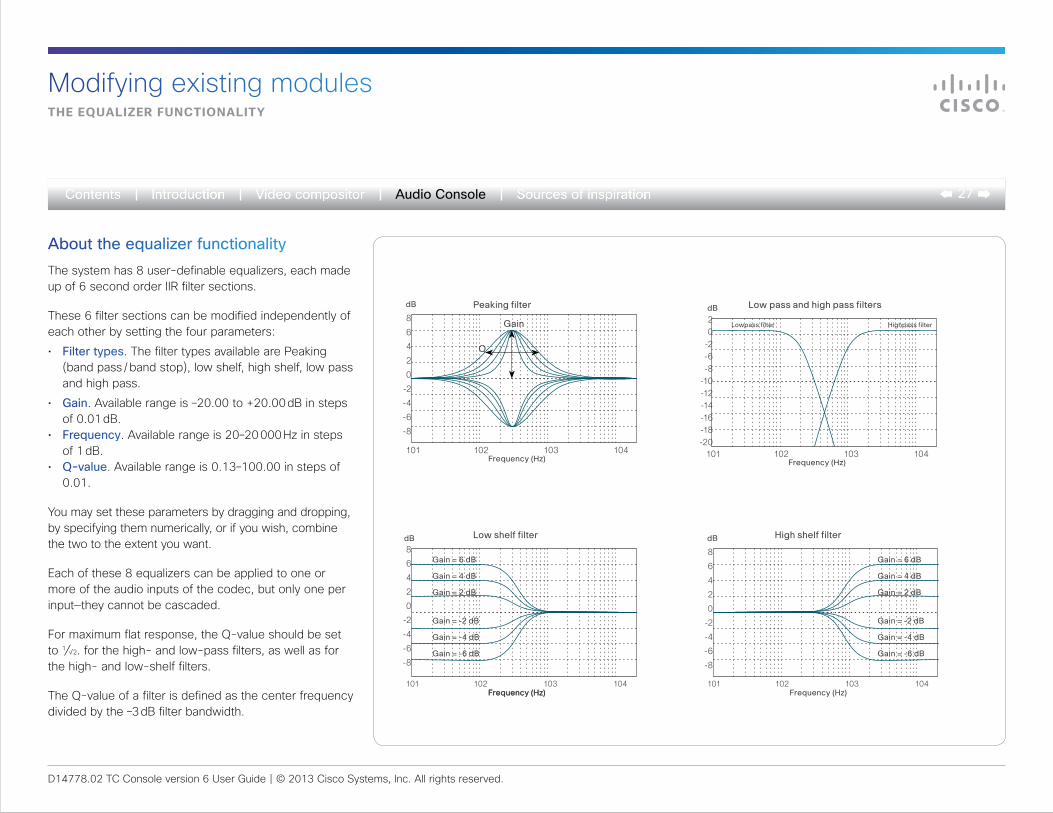
About the equalizer functionalityThe system has 8 user-definable equalizers, each made up of 6 second order IIR filter sections.
These 6 filter sections can be modified independently of each other by setting the four parameters:
• Filter types. The filter types available are Peaking (band pass / band stop), low shelf, high shelf, low pass and high pass.
• Gain. Available range is –20.00 to +20.00 dB in steps of 0.01 dB.
• Frequency. Available range is 20–20 000 Hz in steps of 1 dB.
• Q-value. Available range is 0.13–100.00 in steps of 0.01.
You may set these parameters by dragging and dropping, by specifying them numerically, or if you wish, combine the two to the extent you want.
Each of these 8 equalizers can be applied to one or more of the audio inputs of the codec, but only one per input—they cannot be cascaded.
For maximum flat response, the Q-value should be set to 1⁄√2. for the high- and low-pass filters, as well as for the high- and low-shelf filters.
The Q-value of a filter is defined as the center frequency divided by the –3 dB filter bandwidth.
101 102 103 104 Frequency (Hz)
Peaking filter
Gain
Q
8
6
4
2
0
-2
-4
-6
-8
dB
101 102 103 104 Frequency (Hz)
Low shelf filter
Gain = 6 dB
Gain = 4 dB
Gain = 2 dB
Gain = -2 dB
Gain = -4 dB
Gain = -6 dB
8
6
4
2
0
-2
-4
-6
-8
dB
Frequency (Hz)101 102 103 104
Frequency (Hz)
High shelf filter
8
6
4
2
0
-2
-4
-6
-8
dB
Gain = 6 dB
Gain = 4 dB
Gain = 2 dB
Gain = -2 dB
Gain = -4 dB
Gain = -6 dB
101 102 103 104 Frequency (Hz)
Low pass and high pass filters
Highpass filter20
-2-6-8
-10-12-14-16-18-20
Lowpass filter
dB
the equalizer funCtionality
Modifying existing modules

D14778.02 TC Console version 6 User Guide | © 2013 Cisco Systems, Inc. All rights reserved.
28Audio Console
introduCing the graphiCal equalizer editor
Modifying existing modules
Click on the pencil icon to
start the equalizer editor
A tour of the equalizer editorTo begin editing a frequency response, either click on Equalizer along the top menu bar (see below), or click on the icon (see right). This will launch the Equalizer editor.
You have 8 independent equalizers to choose between. Select which to edit.
The editor displays a line with 6 uniformly distributed points. Click on a point to select it.
Initially, all filters are of the peaking type (band pass / band stop). If you need to employ high pass, low pass, high shelf or low shelf filters instead you will have to enter the More menu.
select which of the 8 equalizer presets to edit
the 6 filter points. you may move these sideways
or vertically
initially, all filters are peaking. Click
here to select other filter types
Click here when done to put
changes into effect
Click to produce drop-list
D14778.02 TC Console version 6 User Guide | © 2013 Cisco Systems, Inc. All rights reserved.
29Audio Console
Creating a simple frequenCy response
Modifying existing modules
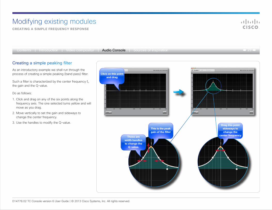
Creating a simple peaking filterAs an introductory example we shall run through the process of creating a simple peaking (band pass) filter.
Such a filter is characterized by the center frequency fc, the gain and the Q-value.
Do as follows:
1. Click and drag on any of the six points along the frequency axis. The one selected turns yellow and will move as you drag.
2. Move vertically to set the gain and sideways to change the center frequency.
3. Use the handles to modify the Q-value.
Click on this point and drag
this is the peak gain of the filter
drag this point sideways to change the
center frequencythese are width handles to change the
q-value.
D14778.02 TC Console version 6 User Guide | © 2013 Cisco Systems, Inc. All rights reserved.
30Audio Console
setting up a more Complex frequenCy response
Modifying existing modules
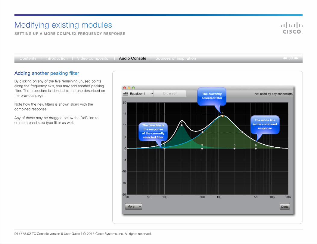
Adding another peaking filterBy clicking on any of the five remaining unused points along the frequency axis, you may add another peaking filter. The procedure is identical to the one described on the previous page.
Note how the new filters is shown along with the combined response.
Any of these may be dragged below the 0 dB line to create a band stop type filter as well.
the white line is the combined
responsethe blue line is the response
of the currently selected filter
the currently selected filter
D14778.02 TC Console version 6 User Guide | © 2013 Cisco Systems, Inc. All rights reserved.
31Audio Console
advanCed equalizer features
Modifying existing modules
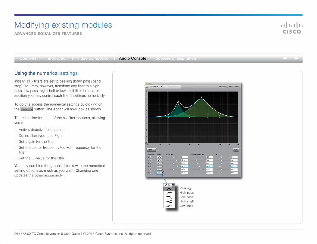
Using the numerical settingsInitially, all 6 filters are set to peaking (band pass / band stop). You may, however, transform any filter to a high pass, low pass, high shelf or low shelf filter instead. In addition you may control each filter’s settings numerically.
To do this access the numerical settings by clicking on the button. The editor will now look as shown.
There is a line for each of the six filter sections, allowing you to:
• Active / deactive that section
• Define filter type (see Fig.)
• Set a gain for the filter
• Set the center frequency / cut-off frequency for the filter
• Set the Q-value for the filter
You may combine the graphical tools with the numerical setting options as much as you want. Changing one updates the other accordingly.
Peaking High pass Low pass High shelf Low shelf
D14778.02 TC Console version 6 User Guide | © 2013 Cisco Systems, Inc. All rights reserved.
32Audio Console
ConneCting an input to an output
Modifying existing modules
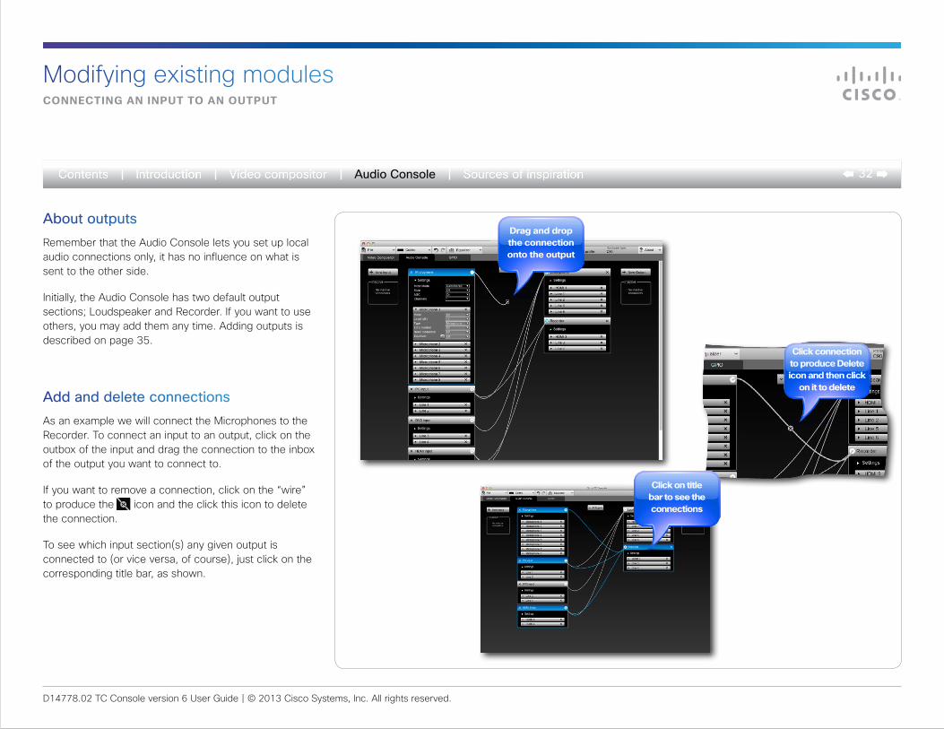
About outputsRemember that the Audio Console lets you set up local audio connections only, it has no influence on what is sent to the other side.
Initially, the Audio Console has two default output sections; Loudspeaker and Recorder. If you want to use others, you may add them any time. Adding outputs is described on page 35.
Add and delete connectionsAs an example we will connect the Microphones to the Recorder. To connect an input to an output, click on the outbox of the input and drag the connection to the inbox of the output you want to connect to.
If you want to remove a connection, click on the “wire” to produce the icon and the click this icon to delete the connection.
To see which input section(s) any given output is connected to (or vice versa, of course), just click on the corresponding title bar, as shown.
drag and drop the connection onto the output
Click connection to produce delete icon and then click
on it to delete
Click on title bar to see the connections
D14778.02 TC Console version 6 User Guide | © 2013 Cisco Systems, Inc. All rights reserved.
33Audio Console
adding gain betWeen input and output
Modifying existing modules
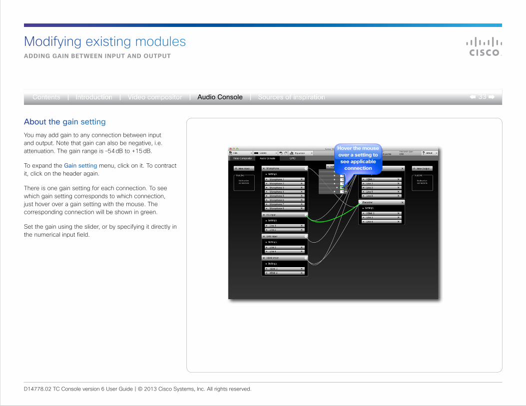
About the gain settingYou may add gain to any connection between input and output. Note that gain can also be negative, i.e. attenuation. The gain range is –54 dB to +15 dB.
To expand the Gain setting menu, click on it. To contract it, click on the header again.
There is one gain setting for each connection. To see which gain setting corresponds to which connection, just hover over a gain setting with the mouse. The corresponding connection will be shown in green.
Set the gain using the slider, or by specifying it directly in the numerical input field.
hover the mouse over a setting to see applicable
connection
D14778.02 TC Console version 6 User Guide | © 2013 Cisco Systems, Inc. All rights reserved.
34Audio Console
adding an input module
Adding or reassigning input modules
...the new input will appear here
Click the arrow next to the settings to
expand the menu
add a new input...
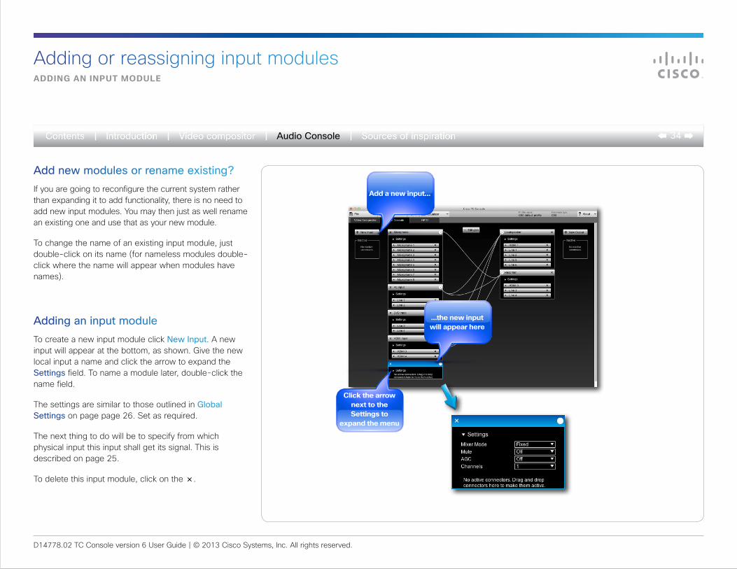
Add new modules or rename existing?If you are going to reconfigure the current system rather than expanding it to add functionality, there is no need to add new input modules. You may then just as well rename an existing one and use that as your new module.
To change the name of an existing input module, just double-click on its name (for nameless modules double-click where the name will appear when modules have names).
Adding an input moduleTo create a new input module click New Input. A new input will appear at the bottom, as shown. Give the new local input a name and click the arrow to expand the Settings field. To name a module later, double-click the name field.
The settings are similar to those outlined in Global Settings on page page 26. Set as required.
The next thing to do will be to specify from which physical input this input shall get its signal. This is described on page 25.
To delete this input module, click on the ×.
D14778.02 TC Console version 6 User Guide | © 2013 Cisco Systems, Inc. All rights reserved.
35Audio Console
add a new output...
...which will appear here
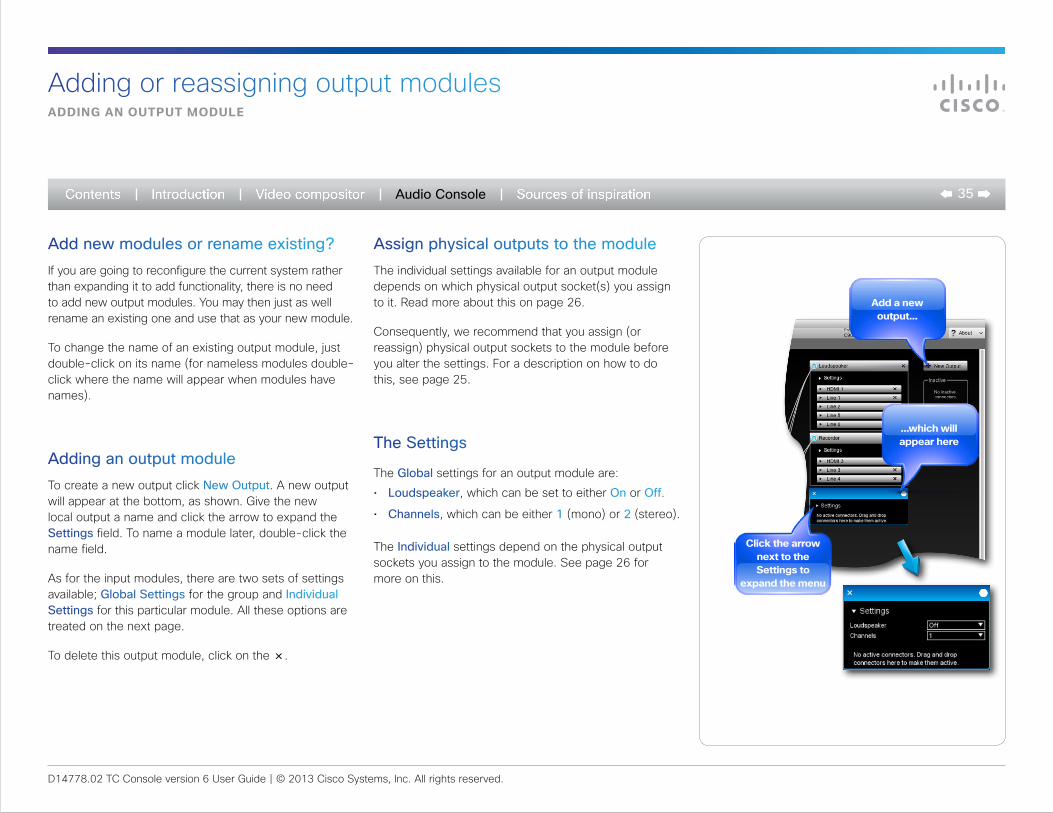
Add new modules or rename existing?If you are going to reconfigure the current system rather than expanding it to add functionality, there is no need to add new output modules. You may then just as well rename an existing one and use that as your new module.
To change the name of an existing output module, just double-click on its name (for nameless modules double-click where the name will appear when modules have names).
Adding an output moduleTo create a new output click New Output. A new output will appear at the bottom, as shown. Give the new local output a name and click the arrow to expand the Settings field. To name a module later, double-click the name field.
As for the input modules, there are two sets of settings available; Global Settings for the group and Individual Settings for this particular module. All these options are treated on the next page.
To delete this output module, click on the ×.
adding an output module
Adding or reassigning output modules
Assign physical outputs to the moduleThe individual settings available for an output module depends on which physical output socket(s) you assign to it. Read more about this on page 26.
Consequently, we recommend that you assign (or reassign) physical output sockets to the module before you alter the settings. For a description on how to do this, see page 25.
The Settings
The Global settings for an output module are:
• Loudspeaker, which can be set to either On or Off.
• Channels, which can be either 1 (mono) or 2 (stereo).
The Individual settings depend on the physical output sockets you assign to the module. See page 26 for more on this.
Click the arrow next to the settings to
expand the menu
D14778.02 TC Console version 6 User Guide | © 2013 Cisco Systems, Inc. All rights reserved.
36Audio Console
General purpose input/outputConfiguring the gpio funCtions
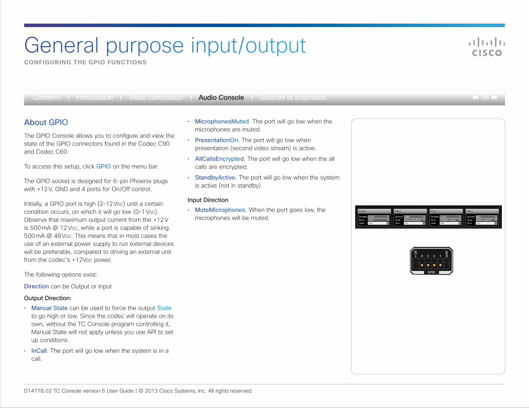
About GPIOThe GPIO Console allows you to configure and view the state of the GPIO connectors found in the Codec C90 and Codec C60.
To access this setup, click GPIO on the menu bar.
The GPIO socket is designed for 6-pin Phoenix plugs with +12 V, GND and 4 ports for On/Off control.
Initially, a GPIO port is high (2–12 Vdc) until a certain condition occurs, on which it will go low (0–1 Vdc). Observe that maximum output current from the +12 V is 500 mA @ 12 Vdc, while a port is capable of sinking 500 mA @ 48 Vdc. This means that in most cases the use of an external power supply to run external devices will be preferable, compared to driving an external unit from the codec’s +12Vdc power.
The following options exist:
Direction can be Output or Input
Output Direction:
• Manual State can be used to force the output State to go high or low. Since the codec will operate on its own, without the TC Console program controlling it, Manual State will not apply unless you use API to set up conditions.
• InCall. The port will go low when the system is in a call.
• MicrophonesMuted. The port will go low when the microphones are muted.
• PresentationOn. The port will go low when presentation (second video stream) is active.
• AllCallsEncrypted. The port will go low when the all calls are encrypted.
• StandbyActive. The port will go low when the system is active (not in standby).
Input Direction
• MuteMicrophones. When the port goes low, the microphones will be muted.
D14778.02 TC Console version 6 User Guide | © 2013 Cisco Systems, Inc. All rights reserved.
37Sources of inspiration
Sources of inspiration
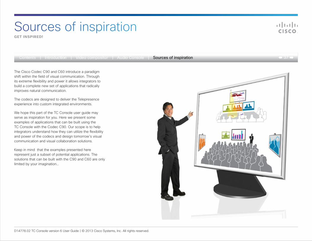
The Cisco Codec C90 and C60 introduce a paradigm shift within the field of visual communication. Through its extreme flexibility and power it allows integrators to build a complete new set of applications that radically improves natural communication.
The codecs are designed to deliver the Telepresence experience into custom integrated environments.
We hope this part of the TC Console user guide may serve as inspiration for you. Here we present some examples of applications that can be built using the TC Console with the Codec C90. Our scope is to help integrators understand how they can utilize the flexibility and power of the codecs and design tomorrow’s visual communication and visual collaboration solutions.
Keep in mind that the examples presented here represent just a subset of potential applications. The solutions that can be built with the C90 and C60 are only limited by your imagination…
get inspired!
D14778.02 TC Console version 6 User Guide | © 2013 Cisco Systems, Inc. All rights reserved.
38Sources of inspiration
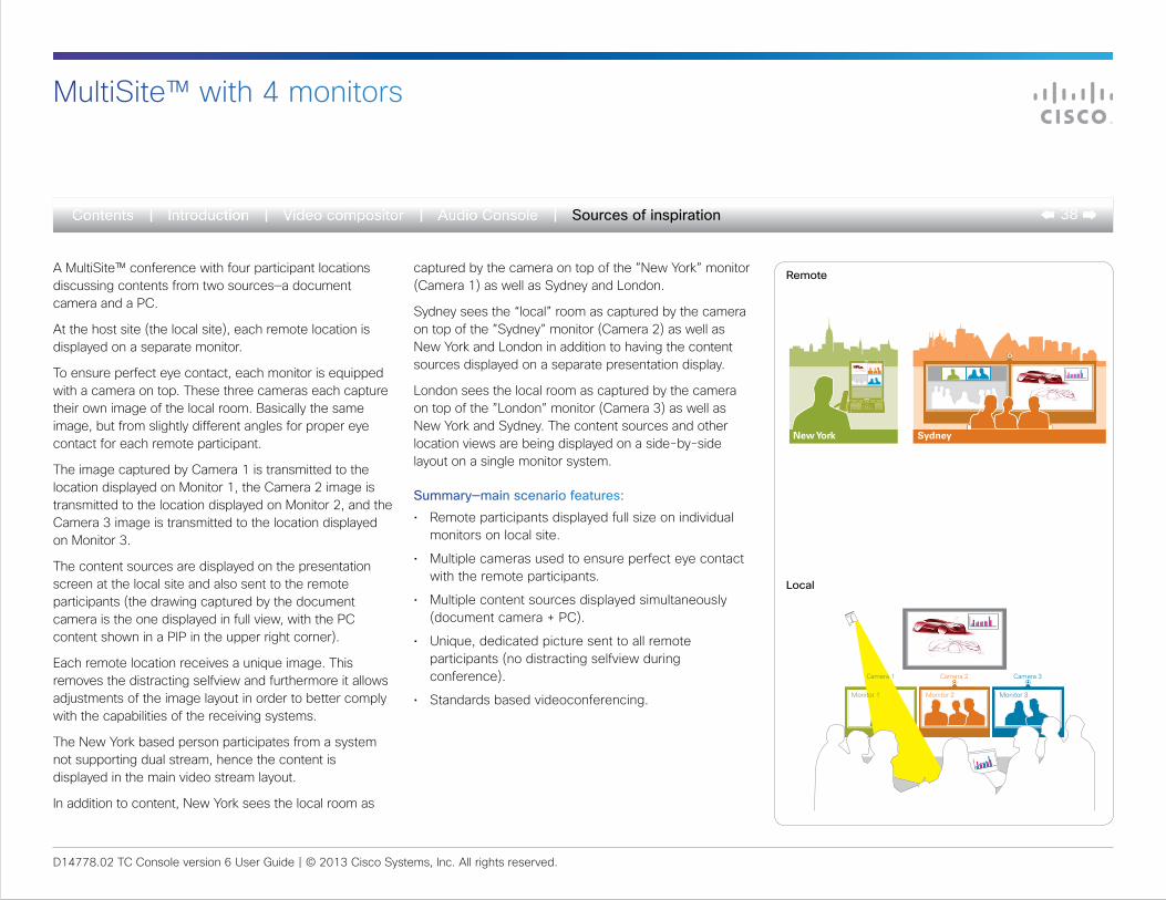
A MultiSite™ conference with four participant locations discussing contents from two sources—a document camera and a PC.
At the host site (the local site), each remote location is displayed on a separate monitor.
To ensure perfect eye contact, each monitor is equipped with a camera on top. These three cameras each capture their own image of the local room. Basically the same image, but from slightly different angles for proper eye contact for each remote participant.
The image captured by Camera 1 is transmitted to the location displayed on Monitor 1, the Camera 2 image is transmitted to the location displayed on Monitor 2, and the Camera 3 image is transmitted to the location displayed on Monitor 3.
The content sources are displayed on the presentation screen at the local site and also sent to the remote participants (the drawing captured by the document camera is the one displayed in full view, with the PC content shown in a PIP in the upper right corner).
Each remote location receives a unique image. This removes the distracting selfview and furthermore it allows adjustments of the image layout in order to better comply with the capabilities of the receiving systems.
The New York based person participates from a system not supporting dual stream, hence the content is displayed in the main video stream layout.
In addition to content, New York sees the local room as
captured by the camera on top of the ”New York” monitor (Camera 1) as well as Sydney and London.
Sydney sees the “local” room as captured by the camera on top of the ”Sydney” monitor (Camera 2) as well as New York and London in addition to having the content sources displayed on a separate presentation display.
London sees the local room as captured by the camera on top of the ”London” monitor (Camera 3) as well as New York and Sydney. The content sources and other location views are being displayed on a side-by-side layout on a single monitor system.
Summary—main scenario features:
• Remote participants displayed full size on individual monitors on local site.
• Multiple cameras used to ensure perfect eye contact with the remote participants.
• Multiple content sources displayed simultaneously (document camera + PC).
• Unique, dedicated picture sent to all remote participants (no distracting selfview during conference).
• Standards based videoconferencing.
New York Sydney
Camera 2 Camera 3Camera 1
Monitor 1 Monitor 2 Monitor 3
Remote
Local
MultiSite™ with 4 monitors
D14778.02 TC Console version 6 User Guide | © 2013 Cisco Systems, Inc. All rights reserved.
39Sources of inspiration
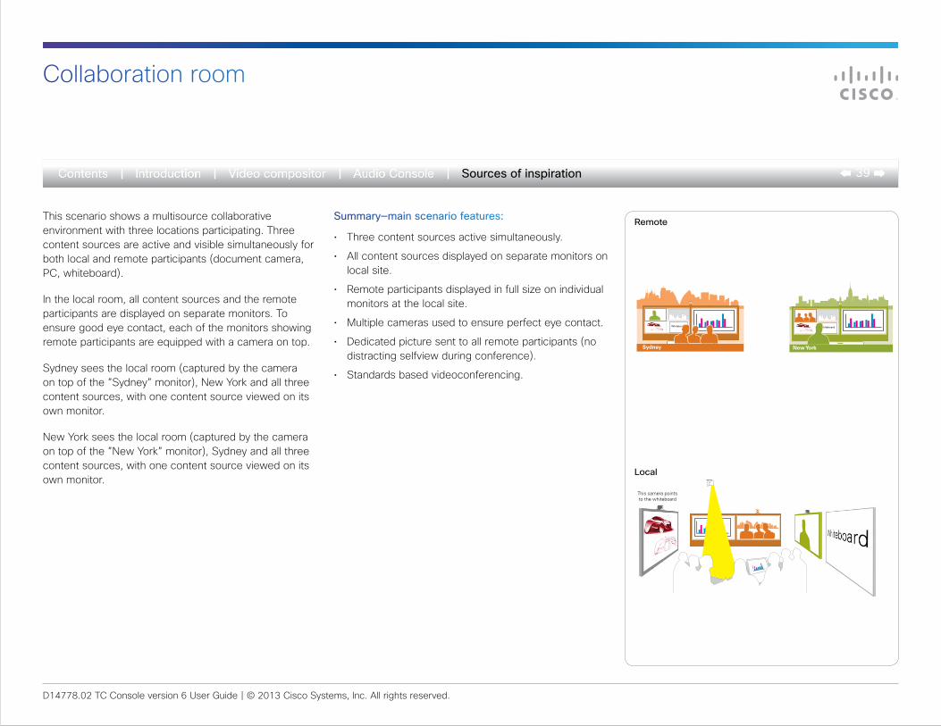
This scenario shows a multisource collaborative environment with three locations participating. Three content sources are active and visible simultaneously for both local and remote participants (document camera, PC, whiteboard).
In the local room, all content sources and the remote participants are displayed on separate monitors. To ensure good eye contact, each of the monitors showing remote participants are equipped with a camera on top.
Sydney sees the local room (captured by the camera on top of the ”Sydney” monitor), New York and all three content sources, with one content source viewed on its own monitor.
New York sees the local room (captured by the camera on top of the ”New York” monitor), Sydney and all three content sources, with one content source viewed on its own monitor.
Summary—main scenario features:
• Three content sources active simultaneously.
• All content sources displayed on separate monitors on local site.
• Remote participants displayed in full size on individual monitors at the local site.
• Multiple cameras used to ensure perfect eye contact.
• Dedicated picture sent to all remote participants (no distracting selfview during conference).
• Standards based videoconferencing.
Whiteboard
New York
Whiteboard
Sydney
This camera points to the whiteboard
Remote
Local
Collaboration room
D14778.02 TC Console version 6 User Guide | © 2013 Cisco Systems, Inc. All rights reserved.
40Sources of inspiration
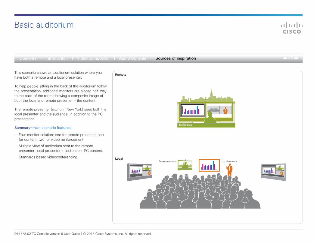
This scenario shows an auditorium solution where you have both a remote and a local presenter.
To help people sitting in the back of the auditorium follow the presentation, additional monitors are placed half-way to the back of the room showing a composite image of both the local and remote presenter + the content.
The remote presenter (sitting in New York) sees both the local presenter and the audience, in addition to the PC presentation.
Summary—main scenario features:
• Four monitor solution; one for remote presenter, one for content, two for video reinforcement.
• Multiple view of auditorium sent to the remote. presenter; local presenter + audience + PC content.
• Standards based videoconferencing.Local presenterRemote presenter
New York
Remote
Local
Basic auditorium
D14778.02 TC Console version 6 User Guide | © 2013 Cisco Systems, Inc. All rights reserved.
41Sources of inspiration
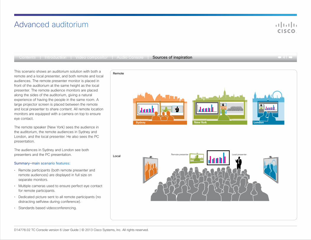
This scenario shows an auditorium solution with both a remote and a local presenter, and both remote and local audiences. The remote presenter monitor is placed in front of the auditorium at the same height as the local presenter. The remote audience monitors are placed along the sides of the auditorium, giving a natural experience of having the people in the same room. A large projector screen is placed between the remote and local presenter to share content. All remote location monitors are equipped with a camera on top to ensure eye contact.
The remote speaker (New York) sees the audience in the auditorium, the remote audiences in Sydney and London, and the local presenter. He also sees the PC presentation.
The audiences in Sydney and London see both presenters and the PC presentation.
Summary—main scenario features:
• Remote participants (both remote presenter and remote audiences) are displayed in full size on separate monitors.
• Multiple cameras used to ensure perfect eye contact for remote participants.
• Dedicated picture sent to all remote participants (no distracting selfview during conference).
• Standards based videoconferencing.
Local presenterRemote presenter
Sydney New York
Remote
Local
Advanced auditorium
London
D14778.02 TC Console version 6 User Guide | © 2013 Cisco Systems, Inc. All rights reserved.
42Sources of inspiration
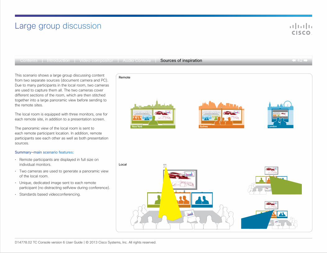
This scenario shows a large group discussing content from two separate sources (document camera and PC). Due to many participants in the local room, two cameras are used to capture them all. The two cameras cover different sections of the room, which are then stitched together into a large panoramic view before sending to the remote sites.
The local room is equipped with three monitors, one for each remote site, in addition to a presentation screen.
The panoramic view of the local room is sent to each remote participant location. In addition, remote participants see each other as well as both presentation sources.
Summary—main scenario features:
• Remote participants are displayed in full size on individual monitors.
• Two cameras are used to generate a panoramic view of the local room.
• Unique, dedicated image sent to each remote participant (no distracting selfview during conference).
• Standards based videoconferencing.
New York Sydney London
Remote
Local
Large group discussion
Cisco and the Cisco Logo are trademarks of Cisco Systems, Inc. and/or its affiliates in the U.S. and other countries. A listing of Cisco’s trademarks can be found at www.cisco.com/go/trademarks. Third-party trademarks mentioned are the property of their respective owners. The use of the word partner does not imply a partnership relationship between Cisco and any other company. (1007R)
THE SPECIFICATIONS AND INFORMATION REGARDING THE PRODUCTS IN THIS MANUAL ARE SUBJECT TO CHANGE WITHOUT NOTICE. ALL STATEMENTS, INFORMATION, AND RECOMMENDATIONS IN THIS MANUAL ARE BELIEVED TO BE ACCURATE BUT ARE PRESENTED WITHOUT WARRANTY OF ANY KIND, EXPRESS OR IMPLIED. USERS MUST TAKE FULL RESPONSIBILITY FOR THEIR APPLICATION OF ANY PRODUCTS.
THE SOFTWARE LICENSE AND LIMITED WARRANTY FOR THE ACCOMPANYING PRODUCT ARE SET FORTH IN THE INFORMATION PACKET THAT SHIPPED WITH THE PRODUCT AND ARE INCORPORATED HEREIN BY THIS REFERENCE. IF YOU ARE UNABLE TO LOCATE THE SOFTWARE LICENSE OR LIMITED WARRANTY, CONTACT YOUR CISCO REPRESENTATIVE FOR A COPY.
The Cisco implementation of TCP header compression is an adaptation of a program developed by the University of California, Berkeley (UCB) as part of UCB’s public domain version of the UNIX operating system. All rights reserved. Copyright © 1981, Regents of the University of California.
NOTWITHSTANDING ANY OTHER WARRANTY HEREIN, ALL DOCUMENT FILES AND SOFTWARE OF THESE SUPPLIERS ARE PROVIDED “AS IS” WITH ALL FAULTS. CISCO AND THE ABOVE-NAMED SUPPLIERS DISCLAIM ALL WARRANTIES, EXPRESSED OR IMPLIED, INCLUDING, WITHOUT LIMITATION, THOSE OF MERCHANTABILITY, FITNESS FOR A PARTICULAR PURPOSE AND NONINFRINGEMENT OR ARISING FROM A COURSE OF DEALING, USAGE, OR TRADE PRACTICE.
IN NO EVENT SHALL CISCO OR ITS SUPPLIERS BE LIABLE FOR ANY INDIRECT, SPECIAL, CONSEQUENTIAL, OR INCIDENTAL DAMAGES, INCLUDING, WITHOUT LIMITATION, LOST PROFITS OR LOSS OR DAMAGE TO DATA ARISING OUT OF THE USE OR INABILITY TO USE THIS MANUAL, EVEN IF CISCO OR ITS SUPPLIERS HAVE BEEN ADVISED OF THE POSSIBILITY OF SUCH DAMAGES.
Cisco and the Cisco Logo are trademarks of Cisco Systems, Inc. and/or its affiliates in the U.S. and other countries. A listing of Cisco’s trademarks can be found at www.cisco.com/go/trademarks. Third party trademarks mentioned are the property of their respective owners. The use of the word partner does not imply a partnership relationship between Cisco and any other company. (1005R)
Any Internet Protocol (IP) addresses and phone numbers used in this document are not intended to be actual addresses and phone numbers. Any examples, command display output, network topology diagrams, and other figures included in the document are shown for illustrative purposes only. Any use of actual IP addresses or phone numbers in illustrative content is unintentional and coincidental.