cisco rv320/rv325 gigabit dual wan vpn router ... rv320/rv325 administration guide contents chapter...
TRANSCRIPT

Cisco RV320/RV325 Gigabit Dual WAN VPN Router
ADMINISTRATION GUIDE

First Published in August 2014Last Update in April 2018
Contents
Chapter 1: Getting Started 5
Using the Getting Started Window 5
Features of the User Interface 6
Chapter 2: Setup Wizard 9
Basic Setup 9
Access Rule Setup 9
Chapter 3: System Summary 11
System Information 11
Configuration (Wizard) 12
Port Activity 12
IPv4 and IPv6 12
Security Status 13
VPN Setting Status 13
Log Setting Status 14
Chapter 4: Setup 15
Setup Network 15
IP Mode 15
WAN Setting 16
USB1 or USB2 Port Settings 25
Password 28
Time 30
DMZ Host 30
(Port) Forwarding 31
Port Address Translation 33
Adding or Editing a Service Name 34
Setting Up One-to-One NAT 35
MAC Address Cloning 36
Cisco RV320/RV325 Administration Guide

Contents
Dynamic DNS 36
Advanced Routing 37
Configuring Dynamic Routing 38
Configuring Static Routing 39
Inbound Load Balance 40
USB Device Update 41
41
Chapter 5: DHCP 43
DHCP Setup 44
DHCP Status 46
Option 82 47
IP and MAC Binding 47
DNS Local Database 49
Router Advertisement (IPv6) 50
Chapter 6: System Management 52
Dual WAN Connections 52
Bandwidth Management 54
SNMP 56
Configuring SNMP 56
SMTP 58
Discovery-Bonjour 59
LLDP Properties 59
Diagnostics 60
Factory Default 61
Firmware Upgrade 61
Language Selection 62
Restart 62
Backup and Restore 63
Cisco RV320/RV325 Administration Guide

Contents
Chapter 7: Port Management 66
Port Setup 66
Port Status 67
Traffic Statistics 67
VLAN Membership 68
Map DSCP to queue 68
Map CoS to DSCP 69
802.1X Configuration 69
Chapter 8: Firewall 72
General 72
Session Timeout 74
Access Rules 74
Content Filter 76
Chapter 9: VPN 78
Summary 78
Gateway to Gateway 80
Add a New Tunnel 81
Local Group Setup 81
Advanced Settings for IKE with Preshared Key and IKE with Certificate 85
Client to Gateway 88
Advanced Settings for IKE 93
FlexVPN (Spoke) 95
VPN Passthrough 99
PPTP Server 99
Chapter 10: OpenVPN 100
Summary 100
OpenVPN Server 101
Cisco RV320/RV325 Administration Guide

Contents
OpenVPN Account 101
Chapter 11: Certificate Management 102
My Certificate 102
Trusted IPsec Certificate 104
OpenVPN Certificate 104
Certificate Generator 105
CSR Authorization 106
Chapter 12: Log 108
System Log 108
System Statistics 111
Processes 111
Chapter 13: User Management 112
Chapter 14: Web Filtering 114
Cisco Small Business Web Filtering Service Supplemental End User License Agreement 115
Chapter 15: Where to Go From Here 120
Cisco RV320/RV325 Administration Guide

Getting Started
Using the Getting Started Window 1
Getting Started
Thank you for choosing the Cisco RV32x router. This chapter includes information
to help you get started using your device.
Using the Getting Started Window
The default settings are sufficient for many small businesses. Network demands
or your Internet Service Provider (ISP) might require modification of the settings.
To use the web interface, you need a PC with Internet Explorer (version 6 and
higher), Firefox, or Safari (for Mac).
To launch the web interface:
STEP 1 Connect a PC to a numbered LAN port on the device. If the PC is configured to
become a DHCP client, an IP address in the 192.168.1.x range is assigned to the
PC.
STEP 2 Start a web browser.
STEP 3 In the address bar, enter the default IP address of the device, 192.168.1.1. The
browser might issue a warning that the web site is untrusted. Continue to the web
site.
STEP 4 When the login page appears, enter the default user name cisco and the default
password cisco (lowercase).
STEP 5 Click Login. The System Summary page appears. Check the Port Activity to see
if a WAN connection is enabled. If not, continue to the next step.
STEP 6 To use the setup wizard to configure your Internet connection, click Setup Wizard
on the System Summary page. Or click Wizard in the navigation tree and in the
Basic Setup section, click Launch Now. Follow the on-screen instructions.
If your web browser displays a warning message about the pop-up window, allow
the blocked content.
STEP 7 To configure other settings, use the links in the navigation tree.
Cisco RV320/RV325 Administration Guide 5
Getting StartedFeatures of the User Interface1
Troubleshooting Tips
If you have trouble connecting to the Internet or the web-based web interface:
• Verify that your web browser is not set to Work Offline.
• Check the local area network connection settings for your Ethernet adapter.
The PC should obtain an IP address through DHCP. Alternatively, the PC can
have a static IP address in the 192.168.1.x range with the default gateway
set to 192.168.1.1 (the default IP address of the device).
• Verify that you entered the correct settings in the Wizard to set up your
Internet connection.
• Reset the modem and the device by powering off both devices. Next,
power on the modem and let it sit idle for about 2 minutes. Then power on
the device. You should now receive a WAN IP address.
• If you have a DSL modem, ask your ISP to put the DSL modem into bridge
mode.
Features of the User Interface
The user interface is designed to make it easy for you to set up and manage your
device.
Navigation
The major modules of the web interface are represented by buttons in the left
navigation pane. Click a button to view more options. Click an option to open a
page.
Pop-Up Windows
Some links and buttons launch pop-up windows that display more information or
related configuration pages. If your web browser displays a warning message
about the pop-up window, allow the blocked content.
Help
To view information about the selected configuration page, click Help near the top
right corner of the web interface. If your web browser displays a warning
message about the pop-up window, allow the blocked content.
6 Cisco RV320/RV325 Administration Guide
Getting Started
Features of the User Interface 1
Logout
To exit the web interface, click Logout near the top right corner of the web
interface. The Login page appears.
Cisco RV320/RV325 Administration Guide 7

Getting StartedFeatures of the User Interface1
8 Cisco RV320/RV325 Administration Guide

2
Setup Wizard
The Setup wizard guides you through the process of configuring the device. The
Access Rule wizard guides you through the process of configuring the network
security policy.
To open this page, select Wizard in the navigation tree.
Basic Setup
Basic Setup
Use the Basic Setup Wizard to change the number of WAN ports or to configure
the Internet connection.
Click Launch Now to run the Basic Setup Wizard. Follow the on-screen
instructions to proceed. Refer to the information from your ISP to enter the
required settings for your connection.
Access Rule Setup
Access Rule Setup
Use the Access Rule Setup Wizard to create firewall access rules. Click Launch
Now to run the Access Rule Setup Wizard. The wizard provides information about
the default rules for this device. Follow the on-screen instructions to proceed.
Cisco RV320/RV325 Administration Guide 9

Setup WizardAccess Rule Setup2
10 Cisco RV320/RV325 Administration Guide

3
System Summary
The System Summary displays information about the current status of the device
connections, status, settings, and logs.
System Information
System information descriptions:
• Serial Number—Serial number of the device.
• Firmware version—Version number of the installed firmware.
• PID VID—Version number of the hardware.
• MD5 Checksum—A value used for file validation.
• LAN IPv4/ Subnet Mask—IPv4 management IP address and subnet mask
of the device.
• LAN IPv6/ Prefix—IPv6 management IP address and prefix.
• Working Mode—Controls the behavior of the device in relation to the WAN
connection. Gateway Mode is selected when the device is hosting an
Internet WAN connection. Router Mode is selected when the device is on a
network that does not have a WAN connection or another device is used to
establish the WAN connection. To change this parameter, click Working
Mode to display the Advanced Routing window.
• System Up time—Length of time in days, hours, and minutes that the
device has been active.
Cisco RV320/RV325 Administration Guide 11

System SummaryConfiguration (Wizard)3
Configuration (Wizard)
To access the Internet connection setup wizard and be prompted through the
process, click Setup Wizard to launch the Setup Wizard.
Port Activity
Port Activity identifies the port interfaces and indicates the status of each port:
• Port ID—Port label.
• Interface—Type of interface: LAN, WAN, or DMZ. Multiple WAN interfaces
are indicated by a number, such as WAN1 or WAN2.
• Status—Status of the port: Disabled (red), Enabled (black), or Connected
(green). The status value is a hyperlink.
IPv4 and IPv6
The IPv4 or IPv6 section identifies the statistics of each WAN port. (The IPv6 tab is
available when Dual-Stack IP is enabled on the Setup Network page.)
WAN Information
The following WAN information is provided:
• IP Address—Public IP address for this interface.
• Default Gateway—Default gateway for this interface.
• DNS—IP address of the DNS server for this interface.
• Dynamic DNS—DDNS settings for this port: Disabled or Enabled.
12 Cisco RV320/RV325 Administration Guide

System Summary
Security Status 3
Security Status
This section displays the status of the security features:
• SPI (Stateful Packet Inspection)—Status of the firewall: On (green) or Off
(red). Tracks the state of network connections, such as TCP streams and
UDP communication, traveling across it. The firewall distinguishes
legitimate packets for different types of connections. Only packets
matching a known active connection are allowed past the firewall; other
packets are rejected.
• DoS (Denial of Service)—Status of the DoS filter: On (green) or Off (red). A
DoS attack is an attempt to make a machine or network resource
unavailable to its intended users.
• Block WAN Request—Makes it difficult for outside users to work their way
into your network by hiding the network ports from Internet devices and
preventing the network from being pinged or detected by other Internet
users. The status is On (green) or Off (red). Block WAN Request
• Remote Management—Indicates that a remote connection for the purpose
of managing the device is allowed or denied. On (green) indicates remote
management is allowed. Off (red) indicates remote management is not
allowed.
• Access Rule—Number of access rules that have been set.
To display detailed information about the security feature, click the label for the
feature.
VPN Setting Status
This section displays the status of the VPN tunnels:
• VPN Tunnel(s) Used—VPN tunnels in use.
• VPN Tunnel(s) Available—VPN tunnels available.
• Easy VPN Tunnel(s) Used—Easy VPN tunnels in use.
• Easy VPN Tunnel(s) Available—Easy VPN tunnels available.
Cisco RV320/RV325 Administration Guide 13

System SummaryLog Setting Status3
• PPTP Tunnel(s) Used—Point-to-Point Tunneling Protocol (PPTP) tunnels in
use. PPTP is a method for implementing virtual private networks. PPTP uses
a control channel over TCP and a Generic Routing Encapsulation (GRE)
tunnel to encapsulate PPP packets.
• PPTP Tunnel(s) Available—PPTP tunnels available.
Log Setting Status
This section displays the status of the logs:
• Syslog Server—Status of syslog: On (green) or Off (red).
• E-mail Log—Status of E-mail log: On (green) or Off (red).
14 Cisco RV320/RV325 Administration Guide

4
Setup
The Setup page displays the configuration settings on the router. Use the Setup >
Network page to set up your LAN, WAN (Internet), DMZ, and so forth.
Setup Network
To open the Network page, click Setup > Network.
Some ISPs require that you assign a hostname and domain name to identify your
device. Default values are provided, but they can be changed as needed:
• Host Name—Keep the default setting or enter a hostname specified by
your ISP.
• Domain Name—Keep the default setting or enter a domain name specified
by your ISP.
IP Mode
In the IP Mode table, choose the type of addressing to use on the networks:
• IPv4 Only—Only IPv4 addressing.
• Dual-Stack IP—IPv4 and IPv6 addressing. After saving the parameters,
you can configure both IPv4 and IPv6 addresses for the LAN, WAN, and
DMZ networks.
Cisco RV320/RV325 Administration Guide 15
SetupSetup Network4
Adding or Editing an IPv4 Network
By default one IPv4 LAN subnetwork is configured, 192.168.1.1. One subnetwork is
usually sufficient for most small businesses. The firewall denies access if a LAN
device source IP address is on a subnetwork that is not specifically allowed. You
can allow traffic from other subnetworks and use this device as an edge router
that provides Internet connectivity to a network.
STEP 1 Click the IPv4 tab to display the Multiple Subnet table.
STEP 2 To add a subnetwork, click Add. IP Address and Subnet Mask fields display in the
columns. After you click Save, you can edit the subnetwork to be part of a VLAN,
manage IP addresses through the DHCP server, or set TFTP server parameters.
STEP 3 Enter the device IP Address and Subnet Mask.
STEP 4 Click Save to save your changes or click Cancel to undo them.
To edit a subnetwork, select the IPv4 subnetwork to be modified and click Edit.
The DHCP Setup section describes the process for modifying the subnetwork
parameters.
Editing the IPv6 Address Prefix
If you enabled Dual-Stack IP for the IP Mode, you can configure the IPv6 prefix.
To configure the IPv6 prefix, click the IPv6 tab, select the IPv6 prefix, and click
Edit. The default IP address is fc00::1, and the default prefix length is 7. The IPv6
tab is available only if Dual-Stack IP is enabled in the IP Mode table. The DHCP
Setup window appears.
WAN Setting
The WAN Setting table displays the interface, such as USB1, WAN1, or WAN2, and
connection type. The settings for the interfaces can be modified.
NOTE If you are running IPv6, select the IPv6 tab before selecting the WAN interface to
configure. Otherwise, the IPv6 parameters are not displayed in the WAN
Connections Settings window.
16 Cisco RV320/RV325 Administration Guide
Setup
Setup Network 4
To configure the WAN Connection Settings, select a WAN interface and click
Edit. WAN Connection Settings appears. Select the WAN Connection Type from
the menu and modify the related parameters as described in these sections:
Obtain an IP Automatically
Choose this option if your ISP dynamically assigns an IP address to the device.
(Most cable modem subscribers use this connection type.) The ISP assigns the
device IP address for this port, including the DNS server IP addresses.
To specify a DNS server, check Use the Following DNS Server Addresses and
enter the IP address of DNS Server 1. Optionally, you can enter a second DNS
server. The first available DNS server is used. If the box is not checked, does the
device rely on DHCP for the DNS addresses?
To set the maximum transmission unit (MTU) size automatically, select Auto.
Otherwise, to set the MTU size manually, select Manual and enter the MTU size.
(The size in bytes of the largest protocol data unit that the layer can pass.)
To configure the IPv6 parameters, check Enable. The DHCPv6 client process and
requests for prefix delegation through the selected interface are enabled. Use this
option when your ISP is capable of sending LAN prefixes by using DHCPv6. If your
ISP does not support this option, manually configure a LAN prefix:
NOTE When DHCP-PD is enabled, manual LAN IPv6 addressing is disabled. When DHCP-
PD is disabled, manual LAN IPv6 addressing is enabled.
• LAN IPv6 Address—Global IPv6 prefix that was assigned by your ISP for
your LAN devices, if applicable. (Check with your ISP for more information.)
• Prefix Length—IPv6 prefix length: The IPv6 network (subnet) is identified
by the initial bits of the address called the prefix. All hosts in the network
have the identical initial bits for their IPv6 address. Enter the number of
common initial bits in the network addresses. The default prefix length is 64.
• LAN Prefix Assignment:
- Without any action—Does not provide Stateless or Stateful IPv6
address for LAN-side PCs.
- Configure to RA automatically—Provides Stateless IPv6 address for
LAN-side PCs.
- Configure to DHCPv6 automatically—Provides Stateful IPv6 address
for LAN-side PCs.
- Configure to RA and DHCPv6 automatically—Provide Stateless and
Stateful IPv6 addresses for LAN-side PCs.
Cisco RV320/RV325 Administration Guide 17

SetupSetup Network4
Static IP
Choose this option if your ISP assigned a permanent IP address to your account.
Enter the settings provided by your ISP:
• Specify WAN IP Address—IP address that your ISP assigned to your
account.
• Subnet Mask (IPv4)—Subnetwork mask.
• Default Gateway Address—IP address of the default gateway.
To specify a DNS server, enter the IP address of DNS Server 1. Optionally, you can
enter a second DNS server. The first available DNS server is used.
To set the maximum transmission unit (MTU) size automatically, select Auto.
Otherwise, to set the MTU size manually, select Manual and enter the MTU size.
(The size in bytes of the largest protocol data unit that the layer can pass.)
To configure the IPv6 parameters:
• LAN IPv6 Address—Global IPv6 prefix that was assigned by your ISP for
your LAN devices, if applicable. (Check with your ISP for more information.)
• Prefix Length—IPv6 prefix length: The IPv6 network (subnet) is identified
by the initial bits of the address called the prefix. All hosts in the network
have the identical initial bits for their IPv6 address. Enter the number of
common initial bits in the network addresses. The default prefix length is 64.
• LAN Prefix Assignment
- Without any action—Does not provide Stateless or Stateful IPv6
address for LAN-side PCs.
- Configure to RA automatically—Provides Stateless IPv6 address for
LAN-side PCs.
- Configure to DHCPv6 automatically—Provides Stateful IPv6 address
for LAN-side PCs.
- Configure to RA and DHCPv6 automatically—Provides Stateless and
Stateful IPv6 addresses for LAN-side PCs.
18 Cisco RV320/RV325 Administration Guide
Setup
Setup Network 4
PPPoE
Choose this option if your ISP uses PPPoE (Point-to-Point Protocol over Ethernet)
to establish Internet connections (typical for DSL lines). Then enter the settings
provided by your ISP:
• Username and Password—Username and password for your ISP account.
The maximum number of characters for each entry is 255.
• Service Name—A set of services provided by the ISP identified by the
service name.
• Connection Timers—Connection is disconnected after a period of
inactivity.
- Connect on Demand—When this feature is enabled, the device
automatically establishes your connection. If you enabled this feature,
enter the Max Idle Time, the number of minutes that the connection can
be inactive before the connection is terminated. The default maximum
idle time is 5 minutes.
- Keep Alive—Ensures that your router is always connected to the
Internet. When this feature is selected, the router keeps the connection
alive by sending out a few data packets periodically. This option keeps
your connection active indefinitely, even when the link sits idle for an
extended period of time. If you enable this feature, also enter the Redial
Period to specify how often the router verifies your Internet connection.
The default period is 30 seconds.
• Use the Following DNS Server Addresses—Enables obtaining connection
information from DNS servers.
• DNS Server 1 and DNS Server 2—IP address of the DNS servers.
Optionally, you can enter a second DNS server. The first available DNS
server is used.
• MTU—Maximum transmission unit (MTU) size. Select Auto to set the size
automatically. Otherwise, to set the MTU size manually, select Manual and
enter the MTU size. (The size in bytes of the largest protocol data unit that
the layer can pass.)
Cisco RV320/RV325 Administration Guide 19
SetupSetup Network4
To configure the IPv6 parameters, check Enable. The DHCPv6 client process and
requests for prefix delegation through the selected interface are enabled. Use this
option when your ISP is capable of sending LAN prefixes by using DHCPv6. If your
ISP does not support this option, manually configure a LAN prefix:
NOTE When DHCP-PD is enabled, manual LAN IPv6 addressing is disabled. When DHCP-
PD is disabled, manual LAN IPv6 addressing is enabled.
• LAN IPv6 Address—Global IPv6 prefix that was assigned by your ISP for
your LAN devices, if applicable. (Check with your ISP for more information.)
• Prefix Length—IPv6 prefix length. The IPv6 network (subnet) is identified
by the initial bits of the address called the prefix. All hosts in the network
have the identical initial bits for their IPv6 address. Enter the number of
common initial bits in the network addresses. The default prefix length is 64.
• LAN Prefix Assignment:
- Without any action—Does not provide Stateless or Stateful IPv6
address for LAN-side PCs.
- Configure to RA automatically—Provides Stateless IPv6 address for
LAN-side PCs.
- Configure to DHCPv6 automatically—Provides Stateful IPv6 address
for LAN-side PCs.
- Configure to RA and DHCPv6 automatically—Provides Stateless and
Stateful IPv6 addresses for LAN-side PCs.
PPTP (IPv4)
Choose this option if required by your ISP. Point-to-Point Tunneling Protocol (PPTP)
is a service used in Europe and Israel.
• Specify WAN IP Address—IP address that your ISP assigned to your
account.
• Subnet Mask (IPv4)—Subnetwork mask assigned to your account.
• Default Gateway Address—IP address of the default gateway.
• Username and Password—Username and password for your ISP account.
The maximum number of characters is 60.
• Connection Timers—Connection is disconnected after a period of
inactivity.
20 Cisco RV320/RV325 Administration Guide

Setup
Setup Network 4
- Connect on Demand—When this feature is enabled, the device
automatically establishes your connection. If you enabled this feature,
enter the Max Idle Time, the number of minutes that the connection can
be inactive before the connection is terminated. The default maximum
idle time is 5 minutes.
- Keep Alive—Ensures that your router is always connected to the
Internet. When this feature is selected, the router keeps the connection
alive by sending out a few data packets periodically. This option keeps
your connection active indefinitely, even when the link sits idle for an
extended period of time. If you enable this feature, also enter the Redial
Period to specify how often the router verifies your Internet connection.
The default period is 30 seconds.
• MTU—Maximum transmission unit (MTU) size. Select Auto to set the size
automatically. Otherwise, to set the MTU size manually, select Manual and
enter the MTU size. (The size in bytes of the largest protocol data unit that
the layer can pass.)
Transparent Bridge (IPv4)
Choose this option if you are using this router to connect two network segments.
Only one WAN interface can be set as transparent bridge.
• Specify WAN IP Address—External IP address that your ISP assigned to
your account.
• Subnet Mask—Subnet mask specified by your ISP.
• Default Gateway Address—IP address of the default gateway.
• DNS Server 1 and DNS Server 2—IP addresses of the DNS servers.
Optionally, you can enter a second DNS server. The first available DNS
server is used.
• Internal LAN IP Range—Internal LAN IP range that is bridged. The WAN
and LAN of transparent bridge must be on the same subnet.
• MTU—Maximum transmission unit (MTU) size. Select Auto to set the size
automatically. Otherwise, to set the MTU size manually, select Manual and
enter the MTU size. (The size in bytes of the largest protocol data unit that
the layer can pass.)
Stateless Address Autoconfiguration (IPv6)
Choose this option if your ISP uses IPv6 Router Solicitations and Router
Advertisements, hosts on the network learn which network they are connected to,
and once they do, they can automatically configure a host ID on that network.
Cisco RV320/RV325 Administration Guide 21
SetupSetup Network4
To specify a DNS server, enter the IP address of DNS Server 1. Optionally, you can
enter a second DNS server. The first available DNS server is used.
To set the maximum transmission unit (MTU) size automatically, select Auto.
Otherwise, to set the MTU size manually, select Manual and enter the MTU size.
(The size in bytes of the largest protocol data unit that the layer can pass.)
To configure the IPv6 parameters:
• LAN IPv6 Address—Global IPv6 prefix that was assigned by your ISP for
your LAN devices, if applicable. (Check with your ISP for more information.)
• Prefix Length—IPv6 prefix length: The IPv6 network (subnet) is identified
by the initial bits of the address called the prefix. All hosts in the network
have the identical initial bits for their IPv6 address. Enter the number of
common initial bits in the network addresses. The default prefix length is 64.
• LAN Prefix Assignment:
- Without any action—Does not provide Stateless or Stateful IPv6
address for LAN-side PCs.
- Configure to RA automatically—Provides Stateless IPv6 address for
LAN-side PCs.
- Configure to DHCPv6 automatically—Provides Stateful IPv6 address
for LAN-side PCs.
- Configure to RA and DHCPv6 automatically—Provides Stateless and
Stateful IPv6 addresses for LAN-side PCs.
IPv6 in IPv4 Tunnel (IPv6)
Choose this option if your ISP uses IPv6 in IPv4 Tunnel to establish Internet
connections.
You must enter an IPv4 Static IP address. Then enter the settings provided by
your ISP:
• Local IPv6 Address—Local IPv6 address for your ISP account.
• Remote IPv4 Address—Remote IPv4 address for your ISP account.
• Remote IPv6 Address—Remote IPv6 address for your ISP account.
• DNS Server 1 and DNS Server 2—IP addresses of the DNS servers.
Optionally, you can enter a second DNS server. The first available DNS
server is used.
22 Cisco RV320/RV325 Administration Guide
Setup
Setup Network 4
• LAN IPv6 Address—Global IPv6 prefix that was assigned by your ISP for
your LAN devices, if applicable. (Check with your ISP for more information.)
• Prefix Length—IPv6 prefix length: The IPv6 network (subnet) is identified
by the initial bits of the address called the prefix. All hosts in the network
have the identical initial bits for their IPv6 address. Enter the number of
common initial bits in the network addresses. The default prefix length is 64.
• LAN Prefix Assignment
- Without any action—Does not provide Stateless or Stateful IPv6
address for LAN-side PCs.
- Configure to RA automatically—Provides Stateless IPv6 address for
LAN-side PCs.
- Configure to DHCPv6 automatically—Provides Stateful IPv6 address
for LAN-side PCs.
- Configure to RA and DHCPv6 automatically—Provides Stateless and
Stateful IPv6 addresses for LAN-side PCs.
6to4 Tunnel (IPv6)
Choose this option to establish an auto-tunnel in an IPv4 network (or real IPv4
Internet connection) across two independent IPv6 networks. Enter the following
parameters:
Relay IPv4 Address—Allows a 6to4 host to communicate with the native IPv6
Internet. It must have a IPv6 default gateway set to a 6to4 address that contains
the IPv4 address of a 6to4 relay router. To avoid the need for users to set this up
manually, the anycast address of 192.88.99.1 has been allocated for sending
packets to a 6to4 relay router.
• DNS Server 1 and DNS Server 2—IP addresses of the DNS servers.
Optionally, you can enter a second DNS server. The first available DNS
server is used.
• LAN IPv6 Address—Global IPv6 prefix that was assigned by your ISP for
your LAN devices, if applicable. (Check with your ISP for more information.)
• Prefix Length—IPv6 prefix length. The IPv6 network (subnet) is identified
by the initial bits of the address called the prefix. All hosts in the network
have the identical initial bits for their IPv6 address. Enter the number of
common initial bits in the network addresses. The default prefix length is 64.
• LAN Prefix Assignment
Cisco RV320/RV325 Administration Guide 23

SetupSetup Network4
- Without any action—Does not provide Stateless or Stateful IPv6
address for LAN-side PCs.
- Configure to RA automatically—Provides Stateless IPv6 address for
LAN-side PCs.
- Configure to DHCPv6 automatically—Provides Stateful IPv6 address
for LAN-side PCs.
- Configure to RA and DHCPv6 automatically—Provides Stateless and
Stateful IPv6 addresses for LAN-side PCs.
IPv6 Rapid Deployment (6rd) Tunnel (IPv6)
Choose this option if your ISP uses 6rd Tunnel (IPv6 Rapid Deployment) to
establish Internet connections. Enter the settings provided by your ISP.
• 6rd Configuration Mode:
- Manual—Manually set 6rd Prefix, Relay IPv4 Address, and IPv4 Mask
Length as provided by your ISP.
- Auto (DHCP)—Use DHCP (option 212) to obtain 6rd Prefix, Relay IPv4
Address, and IPv4 Mask Length.
• 6rd Prefix—6rd Prefix for your ISP account.
• Relay IPv4 Address—Relay IPv4 address for your ISP account.
• IPv4 Mask Length—6rd IPv4 subnet mask length for your ISP account.
(Usually this value is 0.)
• DNS Server 1 and DNS Server 2—IP addresses of the DNS servers.
Optionally, you can enter a second DNS server. The first available DNS
server is used.
• LAN IPv6 Address—Global IPv6 prefix that was assigned by your ISP for
your LAN devices, if applicable. (Check with your ISP for more information.)
• Prefix Length—IPv6 prefix length. The IPv6 network (subnetwork) is
identified by the initial bits of the address called the prefix. All hosts in the
network have the identical initial bits for their IPv6 address. Enter the
number of common initial bits in the network addresses. The default prefix
length is 64.
• LAN Prefix Assignment
- Without any action—Does not provide Stateless or Stateful IPv6
address for LAN-side PCs.
24 Cisco RV320/RV325 Administration Guide
Setup
Setup Network 4
- Configure to RA automatically—Provides Stateless IPv6 address for
LAN-side PCs.
- Configure to DHCPv6 automatically—Provides Stateful IPv6 address
for LAN-side PCs.
- Configure to RA and DHCPv6 automatically—Provides Stateless and
Stateful IPv6 addresses for LAN-side PCs.
USB1 or USB2 Port Settings
USB port configuration manages the connection between this device and the USB
dongle. It also manages WAN port failover (redundancy). Some USB dongles
configure their credentials automatically. Others, such as the
Verizon UML290VW 4G dongle, require manual configuration. Refer to the
manufacturer's documentation for the dongle for more information.
3G/4G Connection
To establish a 3G or 4G connection, enter the following:
• Pin Code and Confirm Pin Code—PIN code associated with your SIM
card. This field is only displayed for GSM SIM cards.
• Access Point Name—Internet network that the mobile device is
connecting to. Enter the access point name provided by your mobile
network service provider. If you do not know the name of the access point,
contact your service provider.
• Dial Number—Number provided by your mobile network service provider
for the Internet connection.
• Username and Password—User name and password provided by your
mobile network service provider.
• Enable DNS—Check the box to enable DNS.
• DNS Server (Required) and DNS Server (Optional)—IP addresses of the
DNS servers. Optionally, you can enter a second DNS server. The first
available DNS server is used.
• MTU—Maximum transmission unit (MTU) size. Select Auto to set the size
automatically. Otherwise, to set the MTU size manually, select Manual and
enter the MTU size. (The size in bytes of the largest protocol data unit that
the layer can pass.)
Cisco RV320/RV325 Administration Guide 25
SetupSetup Network4
Setting Failover and Recovery
While both an Ethernet and mobile network link might be available, only one
connection at a time can be used to establish a WAN link. Whenever one WAN
connection fails, the device attempts to bring up another connection on another
interface. This feature is called Failover. When the primary WAN connection is
restored, it reverts to that path and drops the backup connection. This feature is
called Recovery.
STEP 1 To display the Failover & Recovery window, click Setup > Network.
STEP 2 Select a USB port and click Edit. The Network window appears.
STEP 3 Click the USB Failover tab, and enter the following:
• Operational Mode—When an Ethernet WAN link goes down, the device
attempts to bring up the mobile network link on the USB interface. Configure
failover behavior:
- (3G/4G) Failover Hot Standby—A lost Ethernet WAN port connection
redirects the WAN traffic over the 3G/4G USB link. The USB dongle is
powered on while on standby.
- (3G/4G) Failover Cold Standby—A lost Ethernet WAN port connection
redirects the WAN traffic over the 3G/4G USB link. The USB dongle is
powered off while on standby.
- Primary Mode—The 3G/4G link is used as the primary WAN connection.
• Signal Quality—Indicates the signal strength between the 3G/4G USB
dongle and the access point. Click Refresh to update the reading.
STEP 4 To prevent data overages, select a Charge Count. Traffic (KB) tracks data volume
in kilobytes sent or received over the USB link. Time (min) counts the minutes 3G/
4G connection is active.
• If you choose Traffic (KB), enter the following:
- Premium—Cost in dollars for a given volume of data.
- Extra Charge—Cost in dollars per kilobyte of data if a given volume is
exceeded.
- Stop connection...—Check to enable dropping the connection when the
volume exceeds the given volume.
• If you choose Time (min), enter the following:
- Premium—Cost in dollars for a given period of time.
26 Cisco RV320/RV325 Administration Guide

Setup
Setup Network 4
- Extra Charge—Cost in dollars if a given period of time is exceeded.
- Stop connection...—Check to enable dropping the connection when the
time exceeds the given time.
The window appears:
• Previous Cumulative Time—Amount of time the 3G/4G connection has
been up since being reset.
• Current Cumulative Time—Amount of time that has elapsed since the
device brought up a 3G/4G connection.
• Charge—Estimated cost of the connection since the counters were reset.
STEP 5 Set the Diagnostic behaviors:
• Restart count—Check and enter the day of the month to enable the
counters to be reset on that day. If the value is greater than the number of
days in the month (for example, a value of 31 in a 30-day month), the counters
are restarted on the last day of the month.
• Self-test daily—Check and enter the time-of-day (24-hour clock) to test the
connection. A self-test is considered successful if the device can get an IP
address from the service provider. Failures are sent to the log.
• Log self-test—Check to log all self-test activity. (All test results are sent to
the log.)
STEP 6 Click Save to save your settings.
DMZ Enable
A DMZ is a subnetwork that is open to the public but hidden by a firewall. A
routable IP address is highly recommended for the DMZ configuration. You can
configure the firewall rules to allow access to specific services and ports on the
DMZ from both the LAN or WAN. In the event of an attack on any of the DMZ
nodes, the LAN is not necessarily vulnerable. We recommend that your hosts be
exposed to the WAN (such as web or e-mail servers) on the DMZ network.
To configure DMZ:
STEP 1 Choose Setup > Network and check Enable DMZ. A message appears.
STEP 2 Click Yes to accept the change.
Cisco RV320/RV325 Administration Guide 27
SetupPassword4
STEP 3 Select the DMZ interface in the DMZ Settings table and click Edit. The Edit DMZ
Connection window appears.
STEP 4 Select Subnet to identify a subnetwork for DMZ services and enter the DMZ IP
Address and Subnet Mask. Or select Range to reserve a group of IP addresses
on the same subnetwork for DMZ services and enter the IP address range.
STEP 5 Click Save.
Password
The username and password allow administrative access to the device. The
default username is cisco. The default password is cisco. The username and
password can be changed. We strongly recommend changing the default
password to a strong password.
To open the Password page, click Setup > Password.
If remote management is enabled on the (Firewall) General page, the password
must be changed.
!CAUTION The password cannot be recovered if it is lost or forgotten. If the password is lost
or forgotten, the device must be reset to the factory default settings, removing all
configuration changes. If you are accessing the device remotely and reset the
device to factory defaults, you cannot log into the device until you have established
a local, wired link on the same subnetwork.
After changing the username or password, you are logged out. Log into the device
with your new credentials.
To change the username or password:
STEP 1 Choose Setup > Password.
STEP 2 In the Username field, enter the new username. To keep the current username,
leave this field blank.
STEP 3 In the Old Password field, enter the current password. This is required if you are
changing the username, but keeping the current password.
28 Cisco RV320/RV325 Administration Guide
Setup
Password 4
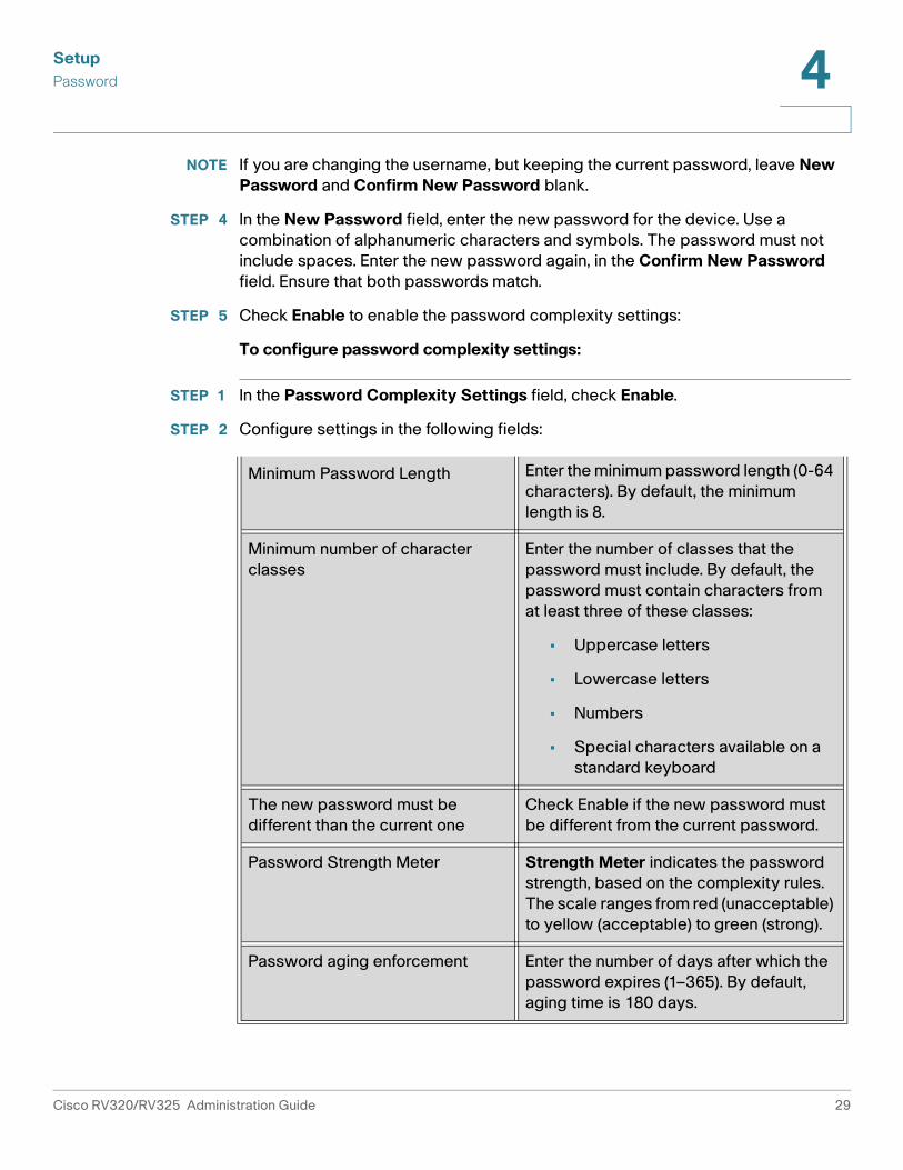
NOTE If you are changing the username, but keeping the current password, leave New
Password and Confirm New Password blank.
STEP 4 In the New Password field, enter the new password for the device. Use a
combination of alphanumeric characters and symbols. The password must not
include spaces. Enter the new password again, in the Confirm New Password
field. Ensure that both passwords match.
STEP 5 Check Enable to enable the password complexity settings:
To configure password complexity settings:
STEP 1 In the Password Complexity Settings field, check Enable.
STEP 2 Configure settings in the following fields:
Minimum Password Length Enter the minimum password length (0-64
characters). By default, the minimum
length is 8.
Minimum number of character
classes
Enter the number of classes that the
password must include. By default, the
password must contain characters from
at least three of these classes:
• Uppercase letters
• Lowercase letters
• Numbers
• Special characters available on a
standard keyboard
The new password must be
different than the current one
Check Enable if the new password must
be different from the current password.
Password Strength Meter Strength Meter indicates the password
strength, based on the complexity rules.
The scale ranges from red (unacceptable)
to yellow (acceptable) to green (strong).
Password aging enforcement Enter the number of days after which the
password expires (1–365). By default,
aging time is 180 days.
Cisco RV320/RV325 Administration Guide 29

SetupTime4
STEP 3 In the Session Timeout field, enter the number of minutes after which the session
must expire. Save your changes.
STEP 4 Click Save.
Time
Time is critical to a network device, so it correctly timestamps the system log and
error messages, and synchronizes data transfer with other network devices.
You can configure the time zone, whether or not to adjust for daylight savings time,
and with which Network Time Protocol (NTP) server to synchronize the date and
time. The router then gets its date and time information from the NTP server.
To open the Time page, click Setup > Time.
To configure NTP and time settings, choose Setup > Time.
• Time Zone—Time zone relative to Greenwich Mean Time (GMT).
• Adjust for Daylight Savings Time—Enable or disable the adjustment for
daylight savings time. Enter the start date in the From fields and enter the
stop date in the To fields.
• Set Date and Time—Auto enables the NTP server. If you chose Auto, enter
the fully qualified NTP Server name or IP address. Manual enables setting
the date and time locally, and uses the device clock to maintain the time. If
you chose Manual, enter the Date and Time.
DMZ Host
DMZ Host allows one host in the LAN to be exposed to the Internet to use services
such as Internet gaming and video conferencing. Access to the DMZ Host from the
Internet can be restricted by using firewall access rules.
To open the DMZ Host page, click Setup > DMZ Host.
To configure a DMZ host, enter a DMZ Private IP Address and click Save.
30 Cisco RV320/RV325 Administration Guide

Setup
(Port) Forwarding 4
(Port) Forwarding
Port forwarding allows public access to services on network devices on the LAN
by opening a specific port or port range for a service, such as FTP. Port triggering
opens a port range for services such as Internet gaming that use alternate ports to
communicate between the server and the LAN host.
To open the port forwarding page, click Setup > Forwarding.
Configuring Port Forwarding
When users make requests for services on your network, the device forwards
those requests to your servers based on the port forwarding parameters. Any
services not specified are denied access. For example, when port number 80
(HTTP) is forwarded to the IP address 192.168.1.2, all HTTP requests on the
interface are forwarded to 192.168.1.2. All other traffic is denied, unless
specifically allowed by another entry.
Use this function to establish a web server or FTP server. Make sure that you enter
a valid IP address. (To run an Internet server, it might be necessary to use a static
IP address.) For added security, outside users are able to communicate with the
server, but they are not allowed to connect to network devices.
To add or edit a service to the table:
STEP 1 To add a service, click Add in the Port Range Forwarding table.
To edit a service, select the row and click Edit.
The fields are open for modification.
STEP 2 Configure the following:
• Select a Service from the drop-down menu. (If a service is not listed, you can
modify the list by following the instructions in the Adding or Editing a
Service Name section.)
• Enter the IP Address of the server.
• Select the Interface.
• Select the Status. Check the box to enable the service. Uncheck the box to
disable the service.
STEP 3 Click Save.
Cisco RV320/RV325 Administration Guide 31

Setup(Port) Forwarding4
Adding or Editing a Service Name
To add or edit an entry on the Service list:
STEP 1 Click Service Management. If the web browser displays a warning about the
pop-up window, allow the blocked content.
STEP 2 To add a service, click Add in the Service Management table.
To edit a service, select the row and click Edit.
The fields are open for modification. If the web browser displays a warning about
the pop-up window, allow the blocked content.
STEP 3 You can have up to 30 services in the list:
• Service Name—Short description.
• Protocol—Required protocol. Refer to the documentation for the service
that you are hosting.
• Port Range—Range of port numbers reserved for this service.
STEP 4 Click Save.
Configuring Port Triggering
Port triggering allows the device to monitor outgoing data for specific port
numbers. The IP address of the client that sent the matching data is remembered
by the device. When the requested data returns through the device, the data is
transmitted to the proper client by using IP addressing and port mapping rules.
Some Internet applications or games use atypical ports to communicate between
the server and LAN host. To use these applications, enter the triggering (outgoing)
port and alternate incoming port in the Port Triggering table.
To add or edit an application name to the table:
STEP 1 Click Setup > Forwarding.
STEP 2 To add an application name, click Add in the Port Range Forwarding table.
32 Cisco RV320/RV325 Administration Guide

Setup
Port Address Translation 4
To edit an application name, select the row and click Edit. The fields are open for
modification.
If the web browser displays a warning about the pop-up window, allow the
blocked content.
STEP 3 Configure the following:
• Application Name—Name of the application.
• Trigger Port Range—Starting and ending port numbers of the trigger port
range. Refer to the documentation for the application for additional
information.
• Incoming Port Range—Starting and ending port numbers of the incoming
port range. Refer to the documentation for the application for additional
information.
STEP 4 Click Save.
Deleting a Table Entry
To delete an entry from a table, click the entry or entries that you want to delete
and click Delete.
Port Address Translation
Port Address Translation (PAT) is an extension of Network Address Translation
(NAT) that permits multiple devices on a LAN to be mapped to a single public IP
address to conserve IP addresses.
PAT is similar to port forwarding except that an incoming packet with destination
port (external port) is translated to a packet different destination port (an internal
port). The Internet Service Provider (ISP) assigns a single IP address to the edge
device. When a computer logs on to the Internet, this device assigns the client a
port number that is appended to the internal IP address, giving the computer a
unique IP address.
If another computer logs on the Internet, this device assigns it the same public IP
address, but a different port number. Although both computers are sharing the
same public IP address, this device knows which computer to send its packets,
because the device uses the port numbers to assign the packets the unique
internal IP address of the computers.
Cisco RV320/RV325 Administration Guide 33
SetupPort Address Translation4
To open this page, select Setup > Port Address Translation.
To add or edit PAT:
STEP 1 To add a service, click Add in the Port Address Translation table.
To edit a service, select the row and click Edit. The fields are open for
modification.
If the web browser displays a warning about the pop-up window, allow the
blocked content.
STEP 2 Select the Service from the drop-down menu. You can have up to 30 services. (If a
service is not listed, you can modify the list by following the instructions in the
Adding or Editing a Service Name section.)
STEP 3 Enter the IP address or the name of the network device where the service resides.
STEP 4 Click Save.
Adding or Editing a Service Name
To add or edit an entry on the Service list:
STEP 1 Click Service Management. If the web browser displays a warning about the
pop-up window, allow the blocked content.
STEP 2 To add a service, click Add in the Service Management table.
To edit a service, select the row and click Edit. The fields are open for
modification.
If the web browser displays a warning about the pop-up window, allow the
blocked content.
STEP 3 You can have up to 30 services in the list:
• Service Name—Short description.
• Protocol—Required protocol. Refer to the documentation for the service
that you are hosting.
• External Port—External port number.
• Internal Port—Internal port number.
34 Cisco RV320/RV325 Administration Guide

Setup
Setting Up One-to-One NAT 4
STEP 4 Click Save.
Setting Up One-to-One NAT
One-to-one NAT creates a relationship that maps a valid WAN IP address to LAN IP
addresses that are hidden from the WAN (Internet) by NAT. This protects the LAN
devices from discovery and attack.
For best results, reserve IP addresses for the internal resources that you want to
reach through one-to-one NAT.
You can map a single LAN IP address or a range of IP addresses to an external
range of WAN IP addresses of equal length (for example, three internal addresses
and three external addresses). The first internal address is mapped to the first
external address, the second IP internal IP address is mapped to the second
external address, and so on.
To open this page, select Setup > One-to-One NAT in the navigation pane.
To enable this feature, check Enable.
To add an entry to the list, click Add and enter the following information:
• Private Range Begin—Starting IP address of the internal IP address range
that you want to map to the public range. Do not include the router
management IP address in this range.
• Public Range Begin—Starting IP address of the public IP address range
provided by the ISP. Do not include the router WAN IP address in this range.
• Range Length—Number of IP addresses in the range. The range length
cannot exceed the number of valid IP addresses. To map a single address,
enter 1.
• Interface—Select the interface from the drop-down list.
To modify an entry, check the entry that you want to modify and click Edit. The
information appears in the text fields. Make the changes and click Save.
Cisco RV320/RV325 Administration Guide 35

SetupMAC Address Cloning4
MAC Address Cloning
Some ISPs require that you register a MAC address (the unique 12-digit
identification code assigned to every network device). If you previously registered
a different MAC address for the device with your ISP, you can select this feature to
clone that address to your device. Otherwise, you must contact your ISP to
change the registered MAC address.
NOTE When MAC Address Clone is enabled, port mirroring does not work.
To open this page, select Setup > MAC Address Clone in the navigation pane.
To clone a MAC address:
STEP 1 Click the Interface radio button.
STEP 2 Click Edit to display the Edit MAC Address Clone page.
• User Defined WAN MAC Address—Click the radio button and enter the 12
digits of the MAC address that you registered with your ISP.
• MAC Address from this PC—Click to use the MAC address of your
computer as the clone MAC address for the device.
STEP 3 Click Save.
Dynamic DNS
Dynamic Domain Name System (DDNS) service assigns a fixed domain name to a
dynamic WAN IP address, so you can host your own web, FTP, or another type of
TCP/IP server on your LAN. Select this feature to configure the WAN interfaces
with your DDNS information.
Before configuring Dynamic DNS on the router, we recommend that you visit
www.dyndns.org and register a domain name. (The service is provided by
DynDNS.org). For users in China, visit www.3322.org to register.
To open this page, select Setup > Dynamic DNS in the navigation pane.
The Edit Dynamic DNS Setup page appears after you select an interface and click
Edit.
36 Cisco RV320/RV325 Administration Guide

Setup
Advanced Routing 4
To edit the DDNS service:
STEP 1 From the DDNS Service list, choose a service.
STEP 2 Enter the information for your account:
• Username—Username for the DDNS account. If you have not registered a
hostname, click Register to go to the DynDNS.com web site, where you can
sign up for free Dynamic DNS service.
• Password—Password for your DDNS account.
• Host Name—Hostname that you registered with your DDNS provider. For
example, if your hostname is myhouse.dyndns.org, then enter myhouse in
the first field, dyndns in the second field, and org in the last field.
• Update Period—Input the value of hours when dynamic DNS setup updates.
It is 360 hours by default.
The following read-only information appears:
• Internet IP Address—WAN IP address for the interface.
• Status—Status of the DDNS. If the status information indicates an error,
make sure that you have correctly entered the information for your account
with your DDNS service.
STEP 3 Click Save.
Advanced Routing
This feature enables dynamic routing and adds static routes to the routing table for
IPv4 and IPv6.
To view the routing table, click View Routing Table. Click Refresh to update the
data. Click Close to close the pop-up window.
Cisco RV320/RV325 Administration Guide 37

SetupAdvanced Routing4
Configuring Dynamic Routing
Dynamic routing constructs routing tables automatically, based on information
carried by routing protocols, and allowing the network to act nearly autonomously
in avoiding network failures and blockages.
To configure IPv4 dynamic routing by using Routing Information Protocol (RIP),
click the IPv4 tab.
To configure IPv6 dynamic routing by using Routing Information Protocol next
generation (RIPng), click the IPv6 tab.
Configuring IPv4 Dynamic Routing
STEP 1 Choose the Working Mode:
• Gateway—Choose this mode if this device is hosting the network
connection to the Internet. This is the default setting.
• Router—Choose this mode if the device is on a network with other routers
and another device is the network gateway to the Internet or this network is
not connected to the Internet. In Router mode, Internet connectivity is
available to the network devices only if you have another router that
functions as the Gateway. Since firewall protection is provided by the
gateway, disable this device firewall.
STEP 2 Enable RIP to allow this device to exchange its routing information automatically
with other routers, and to dynamically adjust its routing tables as network changes
occur. The default setting is Disabled. If you enable this feature, also configure the
following settings:
• Receive RIP versions—Select the RIP protocol for receiving network data:
None, RIPv1, RIPv2, or Both RIP v1 and v2.
RIPv1 is a class-based routing version. It does not include subnet
information and therefore does not support variable length subnet masks
(VLSM). RIPv1 also lacks support for router authentication, making it
vulnerable to attacks. RIPv2 carries a subnet mask and supports password
authentication security.
• Transmit RIP versions—Select the RIP protocol for transmitting network
data: None, RIPv1, RIPv2 - Broadcast, or RIPv2 - Multicast.
RIPv2 - Broadcast (recommended) broadcasts data in the entire subnet.
38 Cisco RV320/RV325 Administration Guide

Setup
Advanced Routing 4
RIPv2 - Multicast sends data to multicast addresses. RIPv2 - Multicast also
helps to avoid unnecessary load by multicasting routing tables to adjacent
routers rather than broadcasting to the entire network.
STEP 3 Click Save.
Configuring IPv6 Dynamic Routing
The IPv6 tab is available if you enabled Dual-Stack IP on the Setup > Network
page.
To enable RIPng, check the RIPng box.
Configuring Static Routing
Static routing can be configured for IPv4 or IPv6. These are routes that do not age
out of the routing table. You can enter up to 30 routes.
To configure a static route, click Add or select an entry and click Edit:
• Destination IP—Subnetwork address of the remote LAN segment. For a
Class C IP domain, the network address is the first three fields of the
Destination LAN IP; the last field should be 0.
• Subnet Mask (IPv4 only)—Subnetwork mask used on the destination LAN
IP domain. For Class C IP domains, the subnet mask is typically
255.255.255.0.
• Prefix Length (IPv6 only)—IPv6 prefix length.
• Default Gateway—IP address of the router of last resort.
• Hop Count—Maximum number of nodes or hops (the maximum is 15 hops)
that a packet passes through before being discarded. A node is any device
on the network, such as a switch or router.
• Interface—Interface to use for this route.
To delete an entry from the list, click the entry that you want to delete, and then
click Delete.
To view current data, click View Routing Table. The Routing Table Entry List
appears. You can click Refresh to update the data, or click Close to close the
pop-up window.
Cisco RV320/RV325 Administration Guide 39

SetupInbound Load Balance4
Inbound Load Balance
Inbound load balancing distributes inbound traffic equally to every WAN port to
make best use of bandwidth. It also can prevent traffic from unequal distribution
and congestion.
To enable and configure inbound load balancing:
STEP 1 Click Enable Inbound Load Balance.
STEP 2 Enter the Domain Name information:
• Domain Name—DNS service provider-assigned domain name.
• TTL (Time-to-Live)—Time interval for DNS inquiries (second, 0~65535). A
long interval affects refresh time. A shorter interval increase the system load,
but the accuracy of the Inbound Load Balance is better. You can adjust this
parameter for the best performance for your network.
• Admin—Administrator E-mail address.
STEP 3 Enter the DNS Server parameters:
• Name Server—DNS server that translates the domain name.
• Interface—WAN interface corresponding to the name server. The system
shows the acquired, enabled WAN IP addresses.
STEP 4 Enter the hostname that provides services, such as the mail server or FTP server
in the Host (Record) Name field and select the WAN IP interface to where inbound
traffic is distributed.
STEP 5 Enter the Alias that assigns several names to one computer host that might
provide several services and the Target, an existing A Record domain name.
STEP 6 Click SPF Settings to add SPF text. SPF (Sender Policy Framework) is an email
validation system that prevents email spam by detecting email spoofing (a
common vulnerability) by verifying sender IP addresses. (Configuring this field is
not required. More information can be found at
http://www.openspf.org/Tools#wizard?mydomain=&x=35&y=6.)
STEP 7 Enter the Mail Server parameters:
• Host Name—Name (without the domain name) of mail host.
• Weight—Order of the mail hosts. The lower number has the highest priority.
40 Cisco RV320/RV325 Administration Guide

Setup
USB Device Update 4
• Mail Server—Name of the server that is saved in the A Record or the name
of an external mail server.
STEP 8 Click Save.
USB Device Update
USB device firmware can be updated by using this network device.
To upgrade a USB device attached to a USB port, browse the file to be uploaded
from a PC to the USB device and click Update.
Cisco RV320/RV325 Administration Guide 41

Setup4
42 Cisco RV320/RV325 Administration Guide

5
DHCP
Dynamic Host Configuration Protocol (DHCP) is a network protocol that is used to
configure network devices to communicate on an IP network. A DHCP client uses
the DHCP protocol to acquire configuration information, such as an IP address, a
default route, and one or more DNS server addresses from a DHCP server. The
DHCP client then uses this information to configure its host. Once the configuration
process is complete, the host is able to communicate on the Internet.
The DHCP server maintains a database of available IP addresses and
configuration information. When it receives a request from a client, the DHCP
server determines the network to which the DHCP client is connected, and
allocates an IP address or prefix appropriate for the client, and sends
configuration information appropriate for that client.
The DHCP server and DHCP client must be connected to the same network link. In
larger networks, each network link contains one or more DHCP relay agents.
These DHCP relay agents receive messages from DHCP clients and forward them
to DHCP servers. DHCP servers send responses back to the relay agent, and the
relay agent then sends these responses to the DHCP client on the local network
link.
DHCP servers typically grant IP addresses to clients for a limited interval called a
lease. DHCP clients are responsible for renewing their IP address before that
interval has expired, and must stop using the address once the interval has
expired, if they have not been able to renew it.
DHCP is used for IPv4 and IPv6. While both versions serve the same purpose, the
details of the protocol for IPv4 and IPv6 are sufficiently different that they should
be considered separate protocols.
Cisco RV320/RV325 Administration Guide 43
DHCP
DHCP Setup 5
DHCP Setup
DHCP Setup configures DHCP for IPv4 or IPv6. It also allows some devices to
download their configuration from a TFTP server. When a device starts, if it does
not have both the IP address and TFTP server IP address pre-configured, it sends
a request with Option 66, 67, and 150 to the DHCP server to obtain this information.
DHCP Option 150 is Cisco proprietary. The IEEE standard that similar to this
requirement is Option 66. Like Option 150, Option 66 is used to specify the Name
of the TFTP server. Option 67 provides the boot file name.
Option 82 (DHCP relay agent information option) enables a DHCP relay agent to
include information about itself when forwarding client-originated DHCP packets
to a DHCP server. The DHCP server can use this information to implement IP
addressing or other parameter-assignment policies.
To open this page, select DHCP > DHCP Setup.
To set up DHCP IPv4, click the IPv4 tab. To set up DHCP IPv6, click the IPv6 tab.
Configuring DHCP for IPv4
To configure DHCP for IPv4:
STEP 1 Choose VLAN or Option 82.
STEP 2 If you choose Option 82, add circuit IDs by using DHCP > Option 82. Those circuit
IDs are then listed in the Circuit ID drop-down menu.
If you choose VLAN, select the VLAN from the VLAN ID menu and enter:
• Device IP Address—Management IP address.
• Subnet Mask—Management IP subnetwork mask.
STEP 3 Select the DHCP Mode:
• Disable—Disables DHCP on this device. There are no additional parameters
to complete.
• DHCP Server—Communicates the client DHCP requests to the device
DHCP server.
• DHCP Relay—Passes DHCP requests and replies from another DHCP
server through the device. If DHCP Relay is chosen, enter the Remote DHCP
Server IP address.
Cisco RV320/RV325 Administration Guide 44

DHCP
DHCP Setup 5
• Client Lease Time—Amount of time in minutes that a network user is
allowed to connect to the router with the current IP address. Valid values are
5 to 43200 minutes. The default is 1440 minutes (equal to 24 hours).
• Range Start and Range End—Starting and ending IP addresses that create
a range of IP addresses that can be assigned dynamically. The range can be
up to the maximum number of IP addresses that the server can assign
without overlapping features such as PPTP and SSL VPN . Do not include this
device LAN IP address in this dynamic IP range. For example, if the router
uses the default LAN IP address, 192.168.1.1, the starting value must be
192.168.1.2 or greater.
• DNS Server—DNS service type; where the DNS server IP address is
acquired.
• Static DNS 1 and Static DNS 2—Static IP address of a DNS Server.
(Optionally) if you enter a second DNS server, the device uses the first DNS
server to respond to a request.
• WINS—Optional IP address of a Windows Internet Naming Service (WINS)
server that resolves NetBIOS names to IP addresses. If you do not know the
IP address of the WINS server, use the default, 0.0.0.0.
STEP 4 Enter the TFTP Server parameters:
• TFTP Server Host Name—Host name of the TFTP server.
• TFTP Server IP—IP address of the TFTP server.
• Configuration Filename—Configuration file name of the file used to update
a device.
Configuring DHCP for IPv6
To configure DHCP for IPv6:
STEP 1 Enter the IPv6 Address.
STEP 2 Enter the Prefix Length.
STEP 3 Select the DHCP Mode:
• Disable—Disables DHCP on this device. There are no additional parameters
to complete.
• DHCP Server—Communicates the client DHCP requests to the device
DHCP server.
Cisco RV320/RV325 Administration Guide 45

DHCP
DHCP Status 5
• DHCP Relay—Passes DHCP requests and replies from another DHCP
server through the device.
• Client Lease Time—Amount of time that a network user is allowed to
connect to the router with the current IP address. Enter the amount of time in
minutes. Valid values are 5 to 43200 minutes. The default is 1440 minutes
(equal to 24 hours).
• DNS Server 1 and DNS Server 2—(Optional) IP address of a DNS server. If
you enter a second DNS server, the device uses the first DNS server to
respond. Specifying a DNS server can provide faster access than using a
DNS server that is dynamically assigned. Use the default setting of 0.0.0.0 to
use a dynamically assigned DNS server.
STEP 4 Enter the IPv6 address pool:
• Start Address—Beginning address of the IPv6 address pool.
• End Address—Ending address of the IPv6 address pool.
• Prefix Length—Length of the IPv6 IP address prefix.
DHCP Status
DHCP Status displays the status of the DHCP server and its clients.
To view DHCP status and clients, click the IPv4 tab or the IPv6 tab. For IPv4, select
VLAN or Option 82. For IPv6, select the Prefix.
For the DHCP server, the following information is shown:
• DHCP Server—IP address of the DHCP server.
• Dynamic IP Used—Number of dynamic IP addresses used.
• Static IP Used (IPv4 only)—Number of static IP addresses used.
• DHCP Available—Number of dynamic IP addresses available.
• Total—Total number of dynamic IP addresses managed by the DHCP
server.
The Client Table shows the DHCP client information:
• Client Host Name—Name assigned to a client host.
Cisco RV320/RV325 Administration Guide 46

DHCP
Option 82 5
• IP Address—Dynamic IP address assigned to a client.
• MAC Address (IPv4 only)—MAC address of a client.
• Client Lease Time—Amount of time that a network user can remain
connected to the router with a dynamic IP address.
To release an IPv4 client IP address, select the Client Host Name and click Delete.
Click Refresh to renew the data.
Option 82
Option 82 (DHCP relay agent information option) enables a DHCP relay agent to
include information about itself when forwarding client-originated DHCP packets
to a DHCP server. The DHCP server can use this information to implement IP
addressing or other parameter-assignment policies.
The DHCP Option 82 Configurable Circuit ID enhances validation security by
allowing you to determine what information is provided in the Option 82 Circuit ID
description.
To open this page, select DHCP > Option 82 in the navigation tree.
To add a Circuit ID, click Add. A new row is added to the table. Select the Type
from the drop-down list and enter a Circuit ID, Bitmask and Description.
To edit a Circuit ID, select the row and click Edit. The row is opened for
modification.
IP and MAC Binding
When the device is configured as a DHCP server or for DHCP relay, you can bind
static IP addresses to up to 80network devices, such as a web server or an FTP
server.
Typically the MAC address of a device physically appears on a label on the
bottom panel or back panel of a device.
To open this page, select DHCP > IP & MAC Binding in the navigation tree.
Cisco RV320/RV325 Administration Guide 47

DHCP
IP and MAC Binding 5
Bind IP Addresses by Discovery
To bind known IP addresses to MAC addresses and name the binding:
STEP 1 Click Show Unknown MAC Addresses. The IP & MAC Binding Table appears. If
the web browser displays a message about the pop-up window, allow the
blocked content.
The devices are listed by the IP address and the MAC address. If needed, click
Refresh to update the data.
STEP 2 Enter a descriptive Name.
STEP 3 Check the Enable box. Alternatively, select all devices in the list by clicking the
check box at the top of the Enable column.
STEP 4 Click Save to add the devices to the Static IP list, or click Close to close the pop-
up window without adding the selected devices.
Bind IP Addresses Manually
To add a new binding to the list, click Add and enter the following information:
• Static IPv4 Address—Static IPv4 address. You can enter 0.0.0.0 if you
want the router to assign a static IP address to this device.
• MAC Address—MAC address of the device. Enter the address without
punctuation.
• Name—Descriptive name for the device.
• Enable—Check this box to bind the static IP address to this device.
Edit or Delete Bound Entries
To Edit the settings, select an entry in the list and click Edit. The information
appears in the text fields. Make the changes, and click Save.
To Delete an entry from the list, select the entry to delete, and click Delete. To
select a block of entries, click the first entry, hold down the Shift key, and click the
final entry in the block. To select individual entries, press the Ctrl key while
clicking each entry. To de-select an entry, press the Ctrl key while clicking the
entry.
Cisco RV320/RV325 Administration Guide 48

DHCP
DNS Local Database 5
Using the Static IP List to Block Devices
The Static IP list can be used to control access to your network.
To block access by devices that are not on the list or do not have the correct IP
address:
• Block MAC address on the list with wrong IP address—Check this box to
prevent a device from accessing your network if its IP address has been
changed. For example, if you assigned a static IP address of 192.168.1.100
and someone configures the device to use 192.168.149, the device is not
allowed to connect to your network. This discourages users from changing
their device IP addresses without your permission. Uncheck the box to
allow access regardless of the current IP address assignment.
• Block MAC address not on the list—Check this box to block access from
devices that are not included in the Static IP list. This prevents unknown
devices from accessing your network. Uncheck the box to allow access by
any device that is configured with an IP address in the correct range.
DNS Local Database
Domain Name Service (DNS) matches a domain name to its routable IP address.
You can set up a DNS Local Database that enables the device to act as a local DNS
server for commonly used domain names. Using a local database might be faster
than using an external DNS server. If a requested domain name is not found in the
local database, the request is forwarded to the DNS server that is specified on the
Setup Network >WAN Setting page.
If you enable this feature, you also must configure the client devices to use the
device as the DNS server. By default, Windows computers are set to obtain a DNS
server address automatically from the default gateway.
To change the TCP/IP connection settings, for example, on a PC running Windows,
go to the Local Area Connection Properties > Internet Protocol > TCP/IP
Properties window. Choose Use the following DNS server address, and enter
the LAN IP address of the router as the Preferred DNS Server. For more
information, refer to the documentation for the client that you are configuring.
Cisco RV320/RV325 Administration Guide 49

DHCP
Router Advertisement (IPv6) 5
Add, Edit, or Delete Local DNS Entries
To add a new entry, click Add and enter the following information:
• Host Name—Enter the domain name, such as example.com or
example.org. If you do not include the final level of the domain name,
Microsoft Windows® will automatically append your entry with .com.
• IP Address—Enter the IP address of the resource.
To Edit the settings, select an entry in the list. The information appears in the text
fields. Make the changes, and click Save.
To Delete an entry from the list, select the entry to delete, and click Delete. To
select a block of entries, click the first entry, hold down the Shift key, and click the
final entry in the block. To select individual entries, press the Ctrl key while
clicking each entry. To de-select an entry, press the Ctrl key while clicking the
entry.
Router Advertisement (IPv6)
The RADVD (Router Advertisement Daemon) is used for IPv6 auto-configuration
and routing. When enabled, messages are sent by the router periodically and in
response to solicitations. A host uses the information to learn the prefixes and
parameters for the local network. Disabling this feature effectively disables auto-
configuration, requiring manual configuration of the IPv6 address, subnet prefix,
and default gateway on each device.
This page is available if you enabled Dual-Stack IP on the Setup Network page. If
you did not do so, a message appears when you try to open this page.
To open this page, select DHCP > Router Advertisement in the navigation tree.
To Enable Router Advertisement, check the box and complete the other fields:
• Advertise Mode—Choose one of the following options:
- Unsolicited Multicast—Send Router Advertisement messages to all
interfaces in the multicast group. This option is the default setting. Also
enter the Advertisement Interval; the interval at which Router
Advertisement messages are sent. Enter any value between 10 and
1800 seconds. The default is 30 seconds.
- Unicast only—Send Router Advertisement messages only to well-
known IPv6 addresses.
Cisco RV320/RV325 Administration Guide 50

DHCP
Router Advertisement (IPv6) 5
• RA Flags—Determines whether or not hosts can use DHCPv6 to obtain IP
addresses and related information. The options are:
- Managed—Hosts use an administered, stateful configuration protocol
(DHCPv6) to obtain stateful addresses and other information through
DHCPv6.
- Other—Uses an administered, stateful configuration protocol (DHCPv6)
to obtain other, non-address information, such as DNS server addresses.
• Router Preference—High, Medium, or Low preference metric is used in a
network topology where multi-homed hosts have access to multiple
routers. This metric helps a host to choose an appropriate router. If two
routers are reachable, the one with the higher preference is chosen. These
values are ignored by hosts that do not implement router preference. The
default setting is High.
• MTU—Size of the largest packet that can be sent over the network. The
MTU (Maximum Transmission Unit) is used in Router Advertisement
messages to ensure that all nodes on the network use the same MTU value
when the LAN MTU is not well-known. The default setting is1500 bytes,
which is the standard value for Ethernet networks. For PPPoE connections,
the standard is 1492 bytes. Unless your ISP requires a different setting, this
setting should not be changed.
• Router Lifetime—Time in seconds that the Router Advertisement
messages exist on the route. The default is 3600 seconds.
To add a new subnet, click Add and enter an IPv6 Address, Prefix Length, and
Lifetime.
Cisco RV320/RV325 Administration Guide 51

6
System Management
System Management configures advanced settings, such as diagnostic tools, and
performs tasks such as firmware upgrades, backups, and device reboots.
Dual WAN Connections
Use this feature to configure the settings for your Internet connections, if you are
using more than one WAN interface.
To configure the WAN ports, select System Management > Dual WAN in the
navigation tree.
To configure load balancing choose one of the following modes to manage your
WAN connections:
• Smart Link Backup—Ensures continuous connectivity. If the primary WAN
connection is unavailable, the backup WAN connection is used. Choose the
primary WAN interface from the drop-down menu.
• Load Balance (Auto Mode)—Use both WAN connections simultaneously to
increase the available bandwidth. The router balances the traffic between
the two interfaces in a weighted round-robin method.
NOTE DNS queries are not subject to load balancing.
To configure Interface Settings, select the WAN Interface and click Edit. The
settings window for the interface appears. Enter the following parameters:
Max Bandwidth Provided by ISP
Enter the maximum bandwidth settings as specified by your ISP. If the bandwidth
exceeds the specified number, the router uses another WAN interface for the next
connection.
• Upstream—Maximum upstream bandwidth provided by your ISP. The
default is 10000 kbs. The maximum is 1000000 kbs.
Cisco RV320/RV325 Administration Guide 52

System ManagementDual WAN Connections6
• Downstream—Maximum downstream bandwidth provided by your ISP.
The default is 10000 kbs.
Network Service Detection
Optionally, check the box to allow the device to detect network connectivity by
pinging specified devices and enter the settings as described here:
• Retry count—Number of times to ping a device. The range is 1 to 99999
and the default is 3.
• Retry timeout—Number of seconds to wait between pings. The range is 1
to 9999999 and the default is 10 seconds.
• When Fail—Action taken if a ping test fails:
- Generate the Error Condition in the System Log—Records the failure
in the System Log. There is no failover to the other interface.
- Keep System Log and Remove the Connection—Failover occurs and
the backup interface is used. When the WAN port connectivity is
restored, its traffic is restored.
• Default Gateway, ISP Host, Remote Host, and DNS Lookup Host—
Select the device that you want to ping to determine network connectivity.
For an ISP host or a remote host, enter the IP address. For a DNS Lookup
host, enter a host name or domain name. Uncheck a box if you do not want
to ping this device for network service detection.
Protocol Binding
Protocol Binding requires this interface to be used for specified protocols, source,
and destination addresses. It allows an administrator to bind specific outbound
traffic to a WAN interface. This is commonly used when the two WAN interfaces
have different characteristics, or where certain traffic from LAN to WAN must go
through the same WAN interface.
To add or edit table entries, click Add or Edit and enter the following:
• Service—Service (or All Traffic) to bind to this WAN interface. If a service is
not listed, you can click Service Management to add it. For more
information, see Adding or Editing a Service.
• Source IP and Destination IP—Internal source and the external destination
for the traffic that goes through this WAN port. For a range of IP addresses,
enter the first address in the first field and the final address in the To field.
For a single IP address, enter the same address in both fields.
53 Cisco RV320/RV325 Administration Guide

System Management
Bandwidth Management 6
To enable the protocol binding, check the box to enable this rule, or uncheck the
box to disable it.
To Edit the settings, select an entry in the list. The information appears in the text
fields. Make the changes, and click Save.
To Delete an entry from the list, select the entry to delete, and click Delete. To
select a block of entries, click the first entry, hold down the Shift key, and click the
final entry in the block. To select individual entries, press the Ctrl key while
clicking each entry. To de-select an entry, press the Ctrl key while clicking the
entry.
Adding or Editing a Service
To add a new entry to the Service list or to change an entry, click Service
Management. You can have up to 30 services in the list. If the web browser
displays a warning about the pop-up window, allow the blocked content.
To add a service to the list, click Add and enter the following information:
• Service Name—A short description.
• Protocol—Required protocol. Refer to the documentation for the service
that you are hosting.
• Port Range—Required port range.
To Edit the settings, select an entry in the list and click Edit. The information
appears in the text fields. Make the changes, and click Save.
To Delete an entry from the list, select the entry to delete, and click Delete. To
select a block of entries, click the first entry, hold down the Shift key, and click the
final entry in the block. To select individual entries, press the Ctrl key while
clicking each entry. To de-select an entry, press the Ctrl key while clicking the
entry.
Bandwidth Management
Bandwidth Management adjusts the bandwidth settings for upstream and
downstream traffic and configures Quality of Service (QoS) settings for various
types of traffic, such as voice services.
NOTE If you do not add any rule of QoS, then the total WAN bandwidth is not limited to the
configured Maximum bandwidth value.
Cisco RV320/RV325 Administration Guide 54

System ManagementBandwidth Management6
To open bandwidth management, select System Management > Bandwidth
Management in the navigation tree.
Maximum Bandwidth Provided by ISP
Enter the maximum bandwidth settings as specified by your ISP:
• Upstream—Maximum upstream bandwidth provided by your ISP.
• Downstream—Maximum downstream bandwidth provided by your ISP.
Bandwidth Management Type
Choose one of the following management options:
• Rate Control—Minimum (guaranteed) bandwidth and maximum (limited)
bandwidth for each service or IP address. You can add up to 100 services.
• Priority—Manage the bandwidth by identifying high-priority and low-
priority services.
Rate Control
To add an interface that is subject to bandwidth management, click Add and enter
the settings:
• Interface—Interface that supports the service.
• Service—Service to manage. If a service is not listed, click Service
Management to add a service.
• IP—IP address or range to control.
• Direction—Select Upstream for outbound traffic. Select Downstream for
inbound traffic.
• Min. Rate—Minimum rate in kbs for the guaranteed bandwidth.
• Max. Rate—Maximum rate in kbs for the guaranteed bandwidth.
Check the box to enable the service.
Configure Priority
To add an interface that is subject to bandwidth management, click Add and enter
the settings:
• Interface—Interface that supports the service.
• Service—Service to manage. If a service is not listed, click Service
Management to add a service.
55 Cisco RV320/RV325 Administration Guide

System Management
SNMP 6
• Direction—Select Upstream for outbound traffic. Select Downstream for
inbound traffic.
• Priority—Choose the priority for this service: High or Low. Default priority
level is Medium, which is implied and not shown in the web interface.
Check the box to enable this service.
marker to delimit section; do not delete
To Edit the settings, select an entry in the list and click Edit. The information
appears in the text fields. Make the changes, and click Save.
To Delete an entry from the list, select the entry to delete, and click Delete. To
select a block of entries, click the first entry, hold down the Shift key, and click the
final entry in the block. To select individual entries, press the Ctrl key while
clicking each entry. To de-select an entry, press the Ctrl key while clicking the
entry.
SNMP
Simple Network Management Protocol (SNMP) allows network administrators to
manage, monitor, and receive notifications of critical events as they occur on the
network. The device supports SNMP v1/v2c and SNMP v3. The device supports
standard Management Information Bases (MIBs) such as MIBII, as well as private
MIBs.
The device acts as an SNMP agent that replies to SNMP commands from SNMP
Network Management Systems. The commands it supports are the standard
SNMP commands get/next/set. It also generates trap messages to notify the
SNMP manager when alarm conditions occur. Examples include reboots, power
cycles, and WAN link events.
To open this page, select System Management > SNMP in the navigation tree.
Configuring SNMP
In the SNMP Global Settings, configure the following:
• System Name—Host name for the device.
• System Contact—Name of the network administrator who can be
contacted with updates about the device.
Cisco RV320/RV325 Administration Guide 56

System ManagementSNMP6
• System Location—Network administrator contact information: an E-mail
address, telephone number, or pager number.
• Trap Community Name—Password sent with each trap to the SNMP
manager. The string can be up to 64 alphanumeric characters. The default is
public.
• Enable SNMPv1/v2c—Enables SNMP v1/v2c.
- Get Community Name—Community string for authenticating SNMP
GET commands. You can enter a name up to 64 alphanumeric
characters in length. The default is public.
- Set Community Name—Community string for authenticating SNMP
SET commands. You can enter a name up to 64 alphanumeric characters
in length. The default is private.
- SNMPv1/v2c Trap Receiver IP Address—IP address or domain name
for the server where you are running your SNMP management software.
• Enable SNMPv3—Enables SNMPv3. (Check the box and click Save before
creating SNMP groups and users.) Follow the instructions in Configuring
SNMPv3.
- SNMPv3 Trap Receiver IP Address—IP address or domain name for
the server where you are running your SNMP management software.
- SNMPv3 Trap Receiver User—Username for the server where you are
running your SNMP management software.
Configuring SNMPv3
You can create SNMPv3 groups to manage SNMP MIB access and identify the
users that have access to each group.
To add or edit a group:
STEP 1 Click Add or select a group and click Edit in the Group Table.
STEP 2 Enter the Group Name.
STEP 3 Select the Security Level from the drop-down menu. Selecting Authentication or
Privacy forces users to authenticate by using passwords. When No
Authentication, No Privacy is selected, none of the users in this group are
required to set an authentication password or a privacy password. The default is
No Authentication, No Privacy. Authentication and Privacy passwords require at
least 8 characters.
57 Cisco RV320/RV325 Administration Guide

System Management
SMTP 6
STEP 4 Select the MIBs that the members of the group can access.
STEP 5 Click Save.
To add or edit a user:
STEP 1 Click Add or select a user and click Edit in the User Table.
STEP 2 Enter the User Name.
STEP 3 Select the Group from the drop-down menu.
STEP 4 Select the Authentication Method and enter the Authentication Password.
STEP 5 Select the Privacy Method and enter the Privacy Password.
STEP 6 Click Save.
SMTP
Simple Mail Transfer Protocol (SMTP) is an Internet standard for electronic mail
(email) transmission. To configure the SMTP, please provide the SMTP settings
that will be used to send the Log or OpenVPN config file.
To configure SMTP, select System Management > SMTP, enter the following
settings and click Save.
• Sender—Email address of the sender.
• Mail Server—Name or IP address of the mail server.
• Authentication—Mail server login authentication type.
- None—Without any authentication.
- Login Plain—Authentication in plaintext format.
- TLS—Authentication protocol of the secure connection (for example, Gmail uses TLS authentication option on port 587).
- SSL—Authentication protocol of the secure connection (for example, Gmail uses SSL authentication option on port 465).
• SMTP Port—Simple Mail Transfer Protocol port number.
Cisco RV320/RV325 Administration Guide 58

System ManagementDiscovery-Bonjour6
• Username—email user name. For example:
Mail Server : smtp.gmail.com
Authentication : SSL
SMTP PORT : 465
Username : [email protected]
Password : yyyyyy
Password—email password.
Discovery-Bonjour
Bonjour is a service discovery protocol that locates network devices such as
computers and servers on your LAN. When this feature is enabled, the device
periodically multicasts Bonjour service records to the LAN to advertise its
existence.
NOTE For discovery of Cisco Small Business products, Cisco provides a utility that works
through a simple toolbar on the web browser called FindIt. This utility discovers
Cisco devices in the network and display basic information, such as serial numbers
and IP addresses. For more information and to download the utility, visit
www.cisco.com/go/findit.
To open this page, select System Management > Discovery-Bonjour in the
navigation tree.
To enable Bonjour globally, check the Discovery Enable box. It is enabled by
default.
To enable Bonjour for a VLAN, check the box in the Enable Bonjour column. It is
enabled by default.
LLDP Properties
Link Layer Discovery Protocol (LLDP) is a vendor-neutral protocol in the Internet
Protocol Suite used by network devices for advertising their identity, capabilities,
and neighbors on an IEEE 802 local area network, principally wired Ethernet. LLDP
information is sent by devices from each of their interfaces at a fixed interval, in the
form of an Ethernet frame. Each frame contains one LLDP Data Unit (LLDPDU). Each
LLDPDU is a sequence of type-length-value (TLV) structures.
59 Cisco RV320/RV325 Administration Guide

System Management
Diagnostics 6
To open this page, select System Management > LLDP Properties in the
navigation tree.
To enable LLDP Properties, check the Enable box. (It is enabled by default.)
To enable LLDP Properties on an interface, check the Enable, WAN1 or WAN2
box. (They are enabled by default.)
The LLDP Neighbor table displays this information:
• Local Port—Port identifier.
• ChassisID Subtype—Type of chassis ID (for example, MAC address).
• ChassisID—Identifier of the chassis. Where the chassis ID subtype is a
MAC address, the MAC address of the device is displayed.
• Port ID Subtype—Type of the port identifier.
• Port ID—Port identifier.
• System Name—Name of the device.
• Time to Live—Rate in seconds at which LLDP advertisement updates are
sent.
Diagnostics
The Diagnostic page accesses two built-in tools, DNS Name Lookup and Ping. If
you suspect a problem with connectivity, you can use these tools to investigate
the cause.
To open this page, select System Management > Diagnostic.
To use DNS to learn an IP address, choose DNS Lookup, enter the Lookup
Domain Name, such as www.cisco.com, and click Go. The IP address is
displayed.
To test connectivity to a specified host, choose Ping, enter an IP address or host
name, and click Go. If you do not know the IP address, use the DNS Lookup tool to
learn it. Ping shows if the device is able to send a packet to a remote host and
receive a response.
If the test is successful, the following information appears:
• Status—Status of the test: Testing, Test Succeeded, or Test Failed
Cisco RV320/RV325 Administration Guide 60

System ManagementFactory Default6
• Packets—Number of packets transmitted, number of packets received,
and percentage of packets lost in the Ping test
• Round Trip Time—Minimum, maximum, and average round-trip times for
the Ping test
Factory Default
To open this page, select System Management > Factory Default.
To reboot the device and return all parameters to factory default values, click
Factory Default.
To restore the device to factory default, including the default certificates, click
Factory Default Including Certificates.
Firmware Upgrade
This feature downloads the firmware for your device from a PC or a USB Flash
drive and installs it. The window displays the Firmware Version currently running
on the device.
NOTE If you choose an earlier version of the firmware, the device might reset to factory
default values. We recommend that you backup your configuration by using the
Backup and Restore procedure before updating the firmware.
Upgrading the firmware might take several minutes.
Do not turn off the power, press the reset button, close the browser, or disconnect
the link during this process.
To open this page, select System Management > Firmware Upgrade.
To upload firmware from a PC, select Firmware Upgrade from PC and browse the
file.
To upload firmware from a USB Flash drive, select Firmware Upgrade from USB
and select the file.
61 Cisco RV320/RV325 Administration Guide

System Management
Language Selection 6
Language Selection
Use the Language Selection page to change the language associated with the
user interface and the Help for your device.
For firmware versions after 1.0.2.03, use the Language Selection page to choose a
language.
STEP 1 Navigate to System Management > Language Selection.
STEP 2 From the Select Language drop-down list, choose a language.
STEP 3 Click Save.
Alternatively, you can choose a language in the following ways:
• On the Login page, choose a language from the Language drop-down list.
• On all configuration pages, choose a language from the drop-down list at the
top right-hand corner.
For firmware versions 1.0.2.03 or earlier, use the Language Setup page to choose a
new language by uploading a language pack to your device.
STEP 1 Navigate to System Management > Language Setup.
STEP 2 From the Mode drop-down list, choose Add.
STEP 3 Enter the New Language Name.
STEP 4 Browse the Language File Name, to upload the new language file.
STEP 5 Click Save.
STEP 6 After the language pack is uploaded, choose a language from the drop-down list
at the top right-hand corner on the Language Setup or other configuration pages.
Cisco RV320/RV325 Administration Guide 62

System ManagementRestart6
Restart
When you restart from the Restart page, the router sends out your log file (if
logging is enabled) before the device is reset. The device parameters are
retained.
To open this page, select System Management > Restart in the navigation tree.
To restart the device, click Restart Router.
Backup and Restore
Configuration files can be imported, exported, and copied. The router has two
managed configuration files, startup and mirror. The device loads the startup file
from memory when it boots up into the running configuration and copies the
startup file to the mirror file. Thus, the mirror file contains the last known valid
configuration.
If the Startup configuration file is corrupted or fails for any reason, the mirror
configuration file is used. The router automatically copies the startup configuration
to the mirror configuration after 24 hours of running in stable condition (no reboots
and no configuration changes within the 24-hour period).
Restoring the Settings from a Configuration File
To restore the startup configuration from a file previously saved to a PC or USB
Flash drive:
STEP 1 In the Restore Startup Configuration File section, select Restore Startup
Configuration File from PC and click Browse. Or select Restore Startup
Configuration File from USB and click Refresh.
STEP 2 Select a configuration file (.config).
STEP 3 Click Restore. This process might take up to a minute. If the configuration file
contains a different password than the current device management password, you
are asked to enter this password before the configuration file is restored.
STEP 4 Click System Management > Restart in the navigation tree.
63 Cisco RV320/RV325 Administration Guide

System Management
Backup and Restore 6
The imported settings are not applied until you restart the device by using
System Management > Restart.
Alternatively, press the Reset button on the device for one second and then
release it to restart the router.
Backing Up Configuration Files and Mirror Files
To save your startup and mirror configuration files to your computer or a USB Flash
drive:
STEP 1 Select Backup Configuration File to PC or Backup Configuration File to USB.
STEP 2 Click Backup Startup Configuration or Backup Mirror Configuration. The File
Download window appears.
STEP 3 Click Save and choose a file location. Optionally, enter a filename and click Save.
TIP The default filenames are Startup.config and Mirror.config. The .config extension is
required. For easier identification, it might be helpful to enter a filename that
includes the current date and time.
Copying the Mirror File to the Startup File
You can manually copy the device startup configuration file to the mirror
configuration file.
You can use this process to back up a known good configuration before you make
changes to the startup configuration:
• The startup configuration file is automatically copied to the mirror
configuration file every 24 hours.
• When you save changes to the device parameters, the time counter resets
and the next automatic copy occurs 24 hours later, unless you manually
force the startup file to be saved as the mirror file.
To copy the startup file to the mirror file, click Copy Mirror to Startup. The copy
operation is performed immediately, with no option to cancel. When the operation
is finished, the page refreshes.
Cisco RV320/RV325 Administration Guide 64

System ManagementBackup and Restore6
Sanitizing the Configuration
Sanitizing the configuration deletes the mirror file and the startup configuration file.
To delete the mirror file and the startup configuration file, click Sanitize
Configuration.
!CAUTION The mirror configuration is deleted immediately, with no option to cancel the
operation. The device is reset to use default settings, and is restarted.
Backing Up the Firmware to a USB Flash Drive
To back up the firmware to a Flash drive on the USB port, select the port from the
drop-down menu and click Backup. The device saves the firmware image as
image.bin.
65 Cisco RV320/RV325 Administration Guide

7
Port Management
Use Port Management to enable port mirroring, configure the port settings, and
view the status and traffic statistics of the port. Also, you can configure the VLAN,
802.1x, map the DSCP to a queue, and map the CoS to the DSCP.
Port Setup
You can enable or disable port mirroring, manage LAN/WAN port settings -
including administratively shutting down the port; and enable or disable the EEE,
port priority and port negotiation mode.
Port mirroring is a method of monitoring network traffic. When port mirroring is
enabled, the router sends a copy of all network packets, which are visible on one
or multiple ports, to another dedicated port, where the packets can be analyzed.
To enable port mirroring, select Port Management > Port Setup and check
Mirror All WAN and LAN Traffic to Port 1. All incoming and outgoing packets on
WAN and LAN ports are copied to LAN1.
NOTE When MAC address Cloning is enabled, the port mirroring will not capture WAN
traffic.
The following read-only information is displayed for each port:
• Port ID—Port number or name, as it is labeled on the device
• Interface—Interface type: LAN, WAN, or DMZ
Enter the following settings:
• Disable—Check this box to disable a port. By default, all ports are enabled.
• EEE—Check this box to enable Energy-Efficient Ethernet that reduces the
consumption of power during periods of low data activity.
Cisco RV320/RV325 Administration Guide 66

Port ManagementPort Status7
• Priority—For each port, select the appropriate priority level, High or
Normal. This ensures Quality of Service (QoS) by prioritizing the traffic for
devices on particular ports. For example, you might assign High priority to a
port that is used for gaming or video conferences. The default setting is
Normal.
• Mode—Port speed and duplex mode. When Auto Negotiation is selected,
the device auto-negotiates connection speeds and duplex mode with the
connected device.
Port Status
Port status displays a summary of the port states. Click Refresh to update the
data.
To view the Port Status, select Port Management > Port Status.
The Ethernet table displays the following:
• Port ID—Location of the port.
• Type—Port type.
• Link Status—Status of the connection.
• Port Activity—Status of the port.
• Priority—Port priority set in the Port Setup window.
• Speed Status—Speed of the port, 10 Mbps or 100 Mbps or 1000 Mbps.
• Duplex Status—Duplex mode, Half or Full.
• Auto negotiation—Status of the duplex mode.
Traffic Statistics
The Traffic Statistics allows you to track data traffic for the various devices
connected to your Local Area Network (LAN). To view this page, select Port
Management > Traffic Statistics in the navigation tree.
For the selected port, the Statistics table displays the following:
• Port ID—Location of the port.
67 Cisco RV320/RV325 Administration Guide

Port Management
VLAN Membership 7
• Link Status—Status of the connection.
• Rx Packets—Number of packets received on the port.
• Rx Bytes—Number of packet received, measured in bytes.
• Tx Packets—Number of packets sent on the port.
• Tx Bytes—Number of packet sent, measured in bytes.
• Packet Error—Number of packet errors.
VLAN Membership
All LAN ports are on VLAN 1 by default. To view this page, select Port
Management > VLAN Membership.
To enable VLANs, check VLAN Enable.
To add or edit a VLAN:
• VLAN ID—Identifier for the VLAN.
• Description—Description of this VLAN.
• Inter VLAN Routing—Allows packets to travel between VLANs. A VLAN
with inter-VLAN routing disabled is isolated from other VLANs. Firewall
access rules can be configured to further regulate (allow or deny) the inter-
VLAN traffic.
• For RV320, LAN 1 through LAN 4—A port can be tagged, untagged, or
excluded from the VLAN.
• For RV325, LAN 1 through LAN 14—A port can be tagged, untagged, or
excluded from the VLAN.
Map DSCP to queue
This option groups traffic by classes of service (CoS), ensuring bandwidth and
higher priority for the specified services. All traffic that is not added to the IP
Group uses Intelligent Balancer mode.
Cisco RV320/RV325 Administration Guide 68

Port ManagementMap CoS to DSCP7
To view this page, select Port Management > QoS:CoS/DSCP Setting.
To configure the service queues, select the Queue priority (4 is the highest and 1 is
the lowest) from the drop-down menu.
To set the Differential Services Code Point (DSCP), select the Queue from the
drop-down menus.
Map CoS to DSCP
Differential Services Code Point or DiffServ specifies a simple, scalable method
for classifying and managing network traffic and providing quality of service
(QoS). DiffServ can be used to provide low-latency to critical network traffic such
as voice or streaming media while providing simple best-effort service to non-
critical services such as web traffic or file transfers.
To view this page, select Port Management > DSCP Marking.
To configure the service queues, click Edit and set the Cos/802.1p and enter the
status and priority.
802.1X Configuration
Port-based network access control uses the physical access characteristics of
IEEE 802 LAN infrastructures to provide a means of authenticating and authorizing
devices attached to a LAN port that has point-to-point connection characteristics,
and of preventing access to that port in cases which the authentication and
authorization fails. A port in this context is a single point of attachment to the LAN
infrastructure.
To view this page, select Port Management > 802.1X Configuration. To configure
port-based authentication:
STEP 1 Check Port-based Authentication to enable the feature.
STEP 2 Enter the IP address of the RADIUS server.
STEP 3 Enter the RADIUS UDP Port number.
STEP 4 Enter the RADIUS Secret .
STEP 5 Select the Administration State in the Port table from the drop-down menu:
69 Cisco RV320/RV325 Administration Guide

Port Management
802.1X Configuration 7
• Force Authorized—Is LAN ports' Factory Default state. Authorizes the
interface without authentication.
• Force Unauthorized—Denies the interface access by moving the port into
the unauthorized state. The device does not provide authentication services
to the client through the interface.
NOTE Network access including router's management utility will be blocked
from LAN when all LAN ports are configured with Force Unauthorized.
Reset to factory default will be required if remote access is not
enabled.
• Auto—Enables port-based authentication. The interface moves between an
authorized or unauthorized state based on the authentication exchange
between the device and the client.
STEP 6 Click Save.
Cisco RV320/RV325 Administration Guide 70

Port Management802.1X Configuration7
71 Cisco RV320/RV325 Administration Guide

8
Firewall
The primary objective of a firewall is to control the incoming and outgoing network
traffic by analyzing the data packets and determining whether it should be
allowed through or not, based on a predetermined rule set. A network firewall
builds a bridge between an internal network that is assumed to be secure and
trusted and another network, usually an external (inter)network such as the
Internet that is assumed not to be secure and untrusted.
General
General firewall controls manage the features typically used by Internet browsers
and applications.
To open this page, select Firewall > General in the navigation tree.
Enabling Firewall Features
To enable the Firewall, check Enable. The following firewall features can be
enabled or disabled as needed:
• SPI (Stateful Packet Inspection)—Monitors the state of network
connections (such as TCP streams, UDP communication) traveling across it.
The firewall distinguishes legitimate packets for different types of
connections. Only packets matching a known active connection are allowed
by the firewall; others are rejected.
• DoS (Denial-of-service )—Detects attempts to cause a server overload. In
general terms, DoS attacks are implemented by either forcing the targeted
computer(s) to reset, or consuming its resources so that it can no longer
provide its intended service or obstructing the communication media
between the intended users and the victim so that they can no longer
communicate adequately.
• Block WAN Request—Drops TCP requests and ICMP packets.
Cisco RV320/RV325 Administration Guide 72
FirewallGeneral8
• Remote Management—Allows remote management of the device when
enabled. The port is 443 by default. It can be changed to any user-defined
port. The string will be https://<wan-ip>:<remote-management-port>
• Multicast Pass Through—Allows multicast messages to pass through the
device.
• HTTPS—Hypertext Transfer Protocol Secure is a communications protocol
for secure communication over a computer network, with especially wide
deployment on the Internet.
• SIP ALG—Application layer gateway that augments a firewall or NAT. It
allows customized NAT traversal filters to be plugged into the gateway to
support address and port translation for SIP control/data protocols.
• UPnP—Universal Plug and Play is a set of networking protocols that
permits network devices, such as personal computers, printers, Internet
gateways, Wi-Fi access points, and mobile devices, to seamlessly discover
each other's presence on the network and establish functional network
services for data sharing and communications.
• SSH—Secure Shell (SSH) is a network protocol that provides
administrators with a secure way to access a remote computer. SSH is
widely used by network administrators for managing systems and
applications remotely, allowing them to log in to another computer over a
network, execute commands and move files from one computer to another.
• Remote SSH—Remote secure shell is a method for secure remote login
from one computer to another. It provides several alternative options for
strong authentication, and it protects the communications security and
integrity with strong encryption.
Restricting Web Features
To restrict Web Java, Cookies, ActiveX, or Access to HTTP Proxy Servers
features, select the check box.
To allow only the selected features (Java, Cookies, ActiveX, or Access to HTTP
Proxy Servers) and restrict all others, enable Exception.
Configuring Trusted Domain Names
To add trusted domains, click Add and enter the Domain Name.
To edit a trusted domain, click Edit and modify the Domain Name.
73 Cisco RV320/RV325 Administration Guide

Firewall
Session Timeout 8
Session Timeout
The session timeout is the time it takes for the TCP or UDP session to time out
after a period of idleness.
To open this page, select Firewall > Session Timeout in the navigation tree.
TCP timeout—Input the timeout value of TCP sessions.The default for TCP
timeout is 1800 seconds.
UDP timeout—Input the timeout value of UDP sessions. The default for UDP
timeout is 30 seconds.
Access Rules
Access rules limit access to the subnetwork by allowing or denying access by
specific services or devices identified by their IP address.
To open this page, select Firewall > Access Rules in the navigation tree.
To add or edit a service, click Service Management. This feature is described in
Adding or Editing a Service Name.
Adding an Access Rule to the IPv4 Access Rule Table
To add (or edit) an IPv4 access rule:
STEP 1 Click the IPv4 tab.
STEP 2 Click Add (or select the row and click Edit).
STEP 3 Select the Action, Allow or Deny, for this rule from the drop-down menu.
STEP 4 Select a Service from the drop-down menu.
STEP 5 Select Log packets matching this rule or No Log.
STEP 6 Select the Source Interface from the drop-down menu.
STEP 7 Select the Source IP address from the drop-down menu. If you selected Single,
enter the source IP address. If you selected Range, enter the range of source IP
addresses.
Cisco RV320/RV325 Administration Guide 74

FirewallAccess Rules8
STEP 8 Select the Destination IP address from the drop-down menu. If you selected
Single, enter the destination IP address. If you selected Range, enter the range of
destination IP addresses.
STEP 9 Configure the Scheduling for this access rule by selecting the time. Select
Always for the access rule to be in effect 24 hours a day. Select Interval to set a
time, and enter the hours and minutes that the access rule is effective in the From
and To fields. For example, 07:00 to 20:00. The access rule does not allow
setting two time intervals.
STEP 10 Select the Effective On days of the week.
STEP 11 Click Save.
Adding an Access Rule to the IPv6 Access Rule Table
To add (or edit) an IPv6 access rule:
STEP 1 Click the IPv6 tab.
STEP 2 Click Add (or select the row and click Edit).
STEP 3 Select the Action, Allow or Deny, for this rule from the drop-down menu.
STEP 4 Select the Service from the drop-down menu.
STEP 5 Select the Log from the drop-down menu.
STEP 6 Select the Source Interface from the drop-down menu.
STEP 7 Select the Source IP Prefix Length from the drop-down menu. If you selected
Single, enter the source IP prefix. If you selected Range, enter the starting IP prefix
and the prefix length.
STEP 8 Select the Destination Prefix Length from the drop-down menu. If you selected
Single, enter the destination IP prefix. If you selected Range, enter the starting IP
prefix and the prefix length.
STEP 9 Click Save.
75 Cisco RV320/RV325 Administration Guide

Firewall
Content Filter 8
Content Filter
The Content Filter enables you to restrict access to certain unwanted websites. It
can block access to websites based on the domain names and keywords. It is also
possible to schedule when the content filter is active. To configure and enable the
Content Filter, follow these steps.
STEP 1 Click Firewall > Content Filter.
STEP 2 Check Block Forbidden Domains to block certain web pages or check Accept
Allowed Domains to accept certain web pages.
STEP 3 In the Forbidden Domains section, check Enable to enable the forbidden domains.
STEP 4 In the Forbidden Domain Table, click Add to add the domain name and enter the
name of the domain. Click Edit or Delete to modify an existing domain in the
Forbidden Domain Table.
STEP 5 In the Website Blocking by Keywords section, check Enable to enable the website
blocking.
STEP 6 In the Website Blocking by Keywords table, click Add and enter the keywords to
be blocked.
STEP 7 To specify when the content filtering rules are active, configure the scheduling by
selecting the time from the drop-down list.You can customize the From and To
fields as well as select the day for the content filter to take into effect.
STEP 8 Click Save to save your settings.
Cisco RV320/RV325 Administration Guide 76

FirewallContent Filter8
77 Cisco RV320/RV325 Administration Guide

9
VPN
A VPN is a connection between two endpoints in different networks that allows
private data to be sent securely over a shared or public network, such as the
Internet. This tunnel establishes a private network that can send data securely by
using industry-standard encryption and authentication techniques to secure the
data sent.
Summary
This feature displays general information about the VPN tunnel settings. The
device supports up to 100 tunnels. The Virtual IP Range is reserved for EasyVPN
users or VPN clients that connect to this device with the Mode Configuration
option (described in Advanced Settings for IKE) enabled.
To open this page, select VPN > Summary in the navigation tree.
To set a range of virtual IP addresses to be used for VPN tunnels, click Edit and
enter the following parameters:
• Range Start and Range End—Starting and ending range of IP addresses
used for VPN tunnels.
• DNS Server 1 and DNS Server 2—Optional IP address of a DNS server. If
you enter a second DNS server, the device uses the first DNS server to
respond. Specifying a DNS server can provide faster access than using a
DNS server that is dynamically assigned. Use the default setting of 0.0.0.0 to
use a dynamically assigned DNS server.
• WINS Server1 and WINS Server 2—Optional IP address of a WINS server.
Windows Internet Naming Service resolves NetBIOS names to IP
addresses. If you do not know the IP address of the WINS server, use the
default, 0.0.0.0.
Cisco RV320/RV325 Administration Guide 78

VPNSummary9
• Domain Name 1 through 4—If this router has a static IP address and a
registered domain name, such as MyServer.MyDomain.com, enter the
Domain Name to use for authentication. A domain name can be used only
for one tunnel connection.
The VPN Tunnel Status displays the number of Tunnels Used, Tunnels Available,
Tunnels Enabled, and Tunnels Defined.
Connection Table
The Connection Table displays the entries created in VPN > Gateway to Gateway
and VPN > Client to Gateway. To add a new entry click Add.
• (Tunnel) No—Automatically generated tunnel ID number.
• (Tunnel) Name—Name of this VPN tunnel, such as Los Angeles Office,
Chicago Branch, or New York Division. This description is for reference
purposes; it does not have to match the name used at the other end of the
tunnel.
• Status—Status of the VPN tunnel, Connected or Waiting for Connection.
• Phase2 Enc/Auth/Grp—Phase 2 encryption type (NULL/DES/3DES/AES-
128/AES-192/AES-256), authentication method (NULL/MD5/SHA1), and DH
group number (1/2/5).
• Local Group—IP address and subnet mask of the Local Group.
• Remote Group—IP address and subnet mask of the Remote Group.
• Remote Gateway—IP address of the Remote Gateway.
• Action—Status of the VPN tunnel.
FlexVPN Tunnel Status
The Connection Table displays entries created in VPN >FlexVPN (Spoke). To add
a new tunnel click Add.
• Tunnel Name—Name of the FlexVPN tunnel. This description is for
reference purposes; it does not have to match the name used at the other
end of the tunnel.
• Status—Status of the FlexVPN, Connected or Waiting for Connection.
• Spoke Network—The subnet of Spoke.
• Spoke Virtual IP Address—The virtual IP address of Spoke.
• Hub IP Address—The IP address of hub.
79 Cisco RV320/RV325 Administration Guide

VPN
Gateway to Gateway 9
• Action—Connect or disconnect the tunnel.
Group VPN Status
The Connection Table displays the entries created in VPN > Client to Gateway. To
add a new entry click Add.
• Group Name—Name of this VPN tunnel. This description is for reference
purposes; it does not have to match the name used at the other end of the
tunnel.
• Tunnels—Number of users logged into the group VPN.
• Phase2 Enc/Auth/Grp—Phase 2 encryption type (NULL/DES/3DES/AES-
128/AES-192/AES-256), authentication method (NULL/MD5/SHA1), and DH
group number (1/2/5).
• Local Group—IP address and subnet mask of the Local Group.
• Remote Client—IP address and subnet mask of the Remote Client.
• Details—IP address of the Remote Gateway.
• Action—Connect or disconnect the tunnel.
Gateway to Gateway
In a site-to-site or gateway-to-gateway VPN, the local router at one office connects
to a remote router through a VPN tunnel. Client devices can access network
resources as if they were all at the same site. This model can be used for multiple
users at a remote office.
To open this page, select VPN > Gateway to Gateway in the navigation tree.
A successful connection requires that at least one of the routers to be identifiable
by a static IP address or a Dynamic DNS hostname. Alternatively, if one router has
only a dynamic IP address, you can use any email address as authentication to
establish the connection.
The two ends of the tunnel cannot be on the same subnet. For example, if the
Site A LAN uses the 192.168.1.x/24 subnet, Site B can use 192.168.2.x/24.
Cisco RV320/RV325 Administration Guide 80
VPNGateway to Gateway9
To configure a tunnel, enter corresponding settings (reversing local and remote)
when configuring the two routers. Assume that this router is identified as Router A.
Enter its settings in the Local Group Setup section; enter the settings for the other
router (Router B) in the Remote Group Setup section. When you configure the
other router (Router B), enter its settings in the Local Group Setup section, and
enter the Router A settings in the Remote Group Setup section.
Add a New Tunnel
Enter the settings for a tunnel:
• Tunnel No—ID number of the tunnel.
• Tunnel Name—Name for this VPN tunnel, such as Los Angeles Office,
Chicago Branch, or New York Division. This description is for your reference.
It does not have to match the name used at the other end of the tunnel.
• Interface—WAN port to use for this tunnel.
• Keying Mode—Identifies the tunnel security: Manual, IKE with Preshared
Key, IKE with Certificate.
• Enable—Check this box to enable the VPN tunnel, or uncheck it to disable
the tunnel. By default, the tunnel is enabled.
Local Group Setup
Enter the settings for the Local Group Setup for this router. (Mirror these settings
when configuring the VPN tunnel on the other router. )
NOTE All the options are documented, but only those options that relate to the selected
parameter display.
Keying Mode = Manual or IKE with Preshared Key
• Local Security Gateway Type—Method for identifying the router to
establish the VPN tunnel. The Local Security Gateway is on this router; the
Remote Security Gateway is on the other router. At least one of the routers
must have either a static IP address or a DNS hostname to make a
connection.
- IP Address—This router has a static WAN IP address. The WAN IP
address appears automatically.
81 Cisco RV320/RV325 Administration Guide
VPN
Gateway to Gateway 9
- IP + Certificate—This router has a static WAN IP address that appears
automatically. This option is only available when IKE with Certificate is
selected.
- IP + Domain Name (FQDN) Authentication—This device has a static IP
address and a registered domain name, such as
MyServer.MyDomain.com. Also enter the Domain Name to use for
authentication. The domain name can be used only for one tunnel
connection.
- IP + E-mail Address (USER FQDN) Authentication—This device has a
static IP address and an email address is used for authentication. The
WAN IP address appears automatically. Enter the Email Address to use
for authentication.
- Dynamic IP + Domain Name (FQDN) Authentication—This router has a
dynamic IP address and a registered Dynamic DNS hostname (available
from providers such as DynDNS.com). Enter a Domain Name to use for
authentication. The domain name can be used only for one tunnel
connection.
- Dynamic IP + E-mail Address (USER FQDN) Authentication—This
router has a dynamic IP address and does not have a Dynamic DNS
hostname. Enter an Email Address to use for authentication.
If both routers have dynamic IP addresses (as with PPPoE connections),
do not choose Dynamic IP + Email Addr. for both gateways. For the
remote gateway, choose IP Address and IP Address by DNS Resolved.
• Local Security Group Type—Allows selection of a single IP address, a
Subnet, or an IP (address) Range within a subnet.
- IP—Specify one device that can use this tunnel. Enter the IP Address of
the device.
- Subnet—Allow all devices on a subnet to use the VPN tunnel. Enter the
subnetwork IP Address and Subnet Mask.
Cisco RV320/RV325 Administration Guide 82

VPNGateway to Gateway9
Remote Group Setup
Enter the settings for the Remote Group Setup for this router:
• Remote Security Gateway Type—Method for identifying the router to
establish the VPN tunnel. The Remote Security Gateway is the other router.
At least one of the routers must have either a static IP address or a dynamic
DNS hostname to make a connection.
- IP Only—Static WAN IP address. If you know the IP address of the
remote VPN router, choose IP Address, and enter the address. If you do
not know the IP address of the remote VPN router, select IP by DNS
Resolved, and enter the domain name of the router. A Cisco router can
get the IP address of a remote VPN device by DNS Resolved.
- IP + Domain Name (FQDN) Authentication—This router has a static IP
address and a registered domain name, such as
MyServer.MyDomain.com. If you know the IP address of the remote
VPN router, choose IP Address, and enter the address. If you do not
know the IP address of the remote VPN router, select IP by DNS
Resolved, and enter the domain name of the router. Cisco routers can
get the IP address of remote VPN device by DNS Resolved.
- IP + E-mail Address (USER FQDN) Authentication—This router has a
static IP address and you want to use an E-mail address for
authentication. If you know the IP address of the remote VPN router,
choose IP Address, and enter the IP address. If you do not know the IP
address of the remote VPN router, select IP by DNS Resolved, and enter
the real domain name of the router. Cisco routers can get the IP address
of remote VPN device by DNS Resolved.
- Dynamic IP + Domain Name (FQDN) Authentication—This router has a
dynamic IP address and a registered Dynamic DNS hostname (available
from providers such as DynDNS.com). Enter a Domain Name to use for
authentication. The domain name can be used only for one tunnel
connection.
- Dynamic IP + E-mail Address (USER FQDN) Authentication—This
router has a dynamic IP address and does not have a Dynamic DNS
hostname. Enter an Email Address to use for authentication.
If both routers have dynamic IP addresses (as with PPPoE connections),
do not choose Dynamic IP + Email Address for both gateways. For the
remote gateway, choose IP Address or IP Address by DNS Resolved.
83 Cisco RV320/RV325 Administration Guide

VPN
Gateway to Gateway 9
• Local Security Group Type—LAN resources that can use this tunnel. The
Local Security Group is for this router’s LAN resources; the Remote Security
Group is for the other router’s LAN resources.
- IP Address—Specify one device that can use this tunnel. Enter the IP
Address of the device.
- Subnet—Allow all devices on a subnet to use the VPN tunnel. Enter the
subnetwork IP Address and Subnet Mask.
IPSec Setup
For encryption to be successful, the two ends of a VPN tunnel must agree on the
methods of encryption, decryption, and authentication. Enter exactly the same
settings on both routers.
Enter the settings for Phase 1 and Phase 2. Phase 1 establishes the preshared
keys to create a secure authenticated communication channel. In Phase 2, the IKE
peers use the secure channel to negotiate Security Associations on behalf of
other services such as IPSec. Be sure to enter the same settings when configuring
other router for this tunnel.
• Phase 1 / Phase 2 DH Group—DH (Diffie-Hellman) is a key exchange
protocol. There are three groups of different prime key lengths: Group 1 -
768 bits, Group 2 - 1,024 bits, and Group 5 - 1,536 bits. For faster speed and
lower security, choose Group 1. For slower speed and higher security,
choose Group 5. Group 1 is selected by default.
• Phase 1 / Phase 2 Encryption—Method of encryption for this phase: DES,
3DES, AES-128, AES-192, or AES-256. The method determines the length of
the key used to encrypt or decrypt ESP packets. AES-256 is recommended
because it is more secure.
• Phase 1 / Phase 2 Authentication—Method of authentication for this
phase: MD5 or SHA1. The authentication method determines how the ESP
(Encapsulating Security Payload Protocol) header packets are validated.
MD5 is a one-way hashing algorithm that produces a 128-bit digest. SHA1 is
a one-way hashing algorithm that produces a 160-bit digest. SHA1 is
recommended because it is more secure. Make sure that both ends of the
VPN tunnel use the same authentication method.
• Phase 1 / Phase 2 SA Life Time—Length of time a VPN tunnel is active in
this phase. The default value for Phase 1 is 28800 seconds. The default
value for Phase 2 is 3600 seconds.
Cisco RV320/RV325 Administration Guide 84

VPNGateway to Gateway9
• Perfect Forward Secrecy—When Perfect Forward Secrecy (PFS) is
enabled, IKE Phase 2 negotiation generates new key material for IP traffic
encryption and authentication, so hackers using brute force to break
encryption keys will not be able to obtain future IPSec keys. Check the box
to enable this feature, or uncheck the box to disable this feature. This feature
is recommended.
• Preshared Key—Preshared key to use to authenticate the remote IKE peer.
You can enter up to 30 keyboard characters or hexadecimal values, such as
My_@123 or 4d795f40313233 (' ' " \ are not supported). Both ends of the
VPN tunnel must use the same Preshared Key. It is strongly recommended
that you change the Preshared Key periodically to maximize VPN security.
• Minimum Preshared Key Complexity—Check the Enable box to enable
the Preshared Key Strength Meter.
• Preshared Key Strength Meter—When you enable Minimum Preshared
Key Complexity, this meter indicates the preshared key strength. As you
enter a preshared key, colored bars appear. The scale goes from red (weak)
to yellow (acceptable) to green (strong).
TIP Enter a complex preshared key that includes more than eight characters,
upper- and lowercase letters, numbers, and symbols such as -*^+=.
Advanced Settings for IKE with Preshared Key and IKE with Certificate
For most users, the basic settings should suffice; advanced users can click
Advanced to display the advanced settings. If you change the Advanced settings
on one router, also enter the settings on the other router.
• Aggressive Mode—Two modes of IKE SA negotiation are possible: Main
Mode and Aggressive Mode. If network security is preferred, Main Mode is
recommended. If network speed is preferred, Aggressive Mode is
recommended. Check this box to enable Aggressive Mode, or uncheck the
box to use Main Mode.
• If the Remote Security Gateway Type is one of the Dynamic IP types,
Aggressive Mode is required. The box is checked automatically, and this
setting cannot be changed.
85 Cisco RV320/RV325 Administration Guide

VPN
Gateway to Gateway 9
• Compress (Support IP Payload Compression Protocol (IP Comp))—A
protocol that reduces the size of IP datagrams. Check the box to enable the
router to propose compression when it initiates a connection. If the
responder rejects this proposal, then the router does not implement
compression. When the router is the responder, it accepts compression,
even if compression is not enabled. If you enable this feature for this router,
also enable it on the router at the other end of the tunnel.
• Keep-Alive—Attempts to reestablish the VPN connection if it is dropped.
• AH Hash Algorithm—Authentication Header (AH) protocol describes the
packet format and default standards for packet structure. When AH is the
security protocol, protection is extended forward into the IP header to verify
the integrity of the entire packet. Check the box to use this feature and
select an authentication method: MD5 or SHA1. MD5 produces a 128-bit
digest to authenticate packet data. SHA1 produces a 160-bit digest to
authenticate packet data. Both sides of the tunnel should use the same
algorithm.
• NetBIOS Broadcast—Broadcast messages used for name resolution in
Windows networking to identify resources such as computers, printers, and
file servers. These messages are used by some software applications and
Windows features such as Network Neighborhood. LAN broadcast traffic is
typically not forwarded over a VPN tunnel. However, you can check this box
to allow NetBIOS broadcasts from one end of the tunnel to be rebroadcast
to the other end.
• NAT Traversal—Network Address Translation (NAT) enables users with
private LAN addresses to access Internet resources by using a publicly
routable IP address as the source address. However, for inbound traffic, the
NAT gateway has no automatic method of translating the public IP address
to a particular destination on the private LAN. This issue prevents
successful IPSec exchanges. If your VPN router is behind a NAT gateway,
check this box to enable NAT traversal. The same setting must be used on
both ends of the tunnel.
• Dead Peer Detection (DPD)—Sends periodic HELLO/ACK messages to
check the status of the VPN tunnel. This feature must be enabled on both
ends of the VPN tunnel. Specify the interval between HELLO/ACK
messages in the Interval field.
Cisco RV320/RV325 Administration Guide 86
VPNGateway to Gateway9
• Extended Authentication—Uses an IPSec host username and password to
authenticate the VPN clients or it uses the user database found in User
Management. Both IPSec host and edge device must enable Extended
Authentication. To use the IPSec Host, click the radio button and enter the
User Name and Password. To use the Edge Device, click the radio button
and select the database from the drop-down menu. To add or edit the
database, click Add/Edit to display the User Management window.
• Tunnel Backup—When DPD determines that the remote peer is
unavailable, this feature enables the router to reestablish the VPN tunnel by
using either an alternative IP address for the remote peer or an alternative
local WAN interface. Check the box to enable this feature and enter the
following settings. This feature is available only if Dead Peer Detection is
enabled.
- Remote Backup IP Address—Alternative IP address for the remote
peer, or reenter the WAN IP address that was already set for the remote
gateway.
- Local Interface—WAN interface to use to reestablish the connection.
- VPN Tunnel Backup Idle Time—When the router boots up and the
primary tunnel is not connected within the specified period, the backup
tunnel is used. The default idle time is 30 seconds.
• Split DNS—Sends some of the DNS requests to one DNS server and other
DNS requests to another DNS server, based on specified domain names.
When the router receives an address resolution request from client, it
inspects the domain name. If it matches one of the domain names in the
Split DNS settings, it passes the request to the specified DNS server.
Otherwise, the request is passed to the DNS server that is specified in the
WAN interface settings.
DNS Server 1 and DNS Server 2—IP address of the DNS server to use for
the specified domains. Optionally, specify a secondary DNS server in the
DNS Server 2 field.
Domain Name 1 through Domain Name 4—Specify the domain names for
the DNS servers. Requests for these domains are passed to the specified
DNS server(s).
87 Cisco RV320/RV325 Administration Guide
VPN
Client to Gateway 9
Client to Gateway
This feature creates a new VPN tunnel to allow teleworkers and business travelers
to access your network by using third-party VPN client software, such as
TheGreenBow.
To open this page, select VPN > Client to Gateway in the navigation tree.
Configure a VPN tunnel for one remote user, a group VPN for multiple remote
users, or Easy VPN:
• Tunnel—Creates a tunnel for a single remote user. The tunnel number is
automatically generated.
• Group VPN—Creates a tunnel for a group of users, eliminating the need to
configure individual users. All of the remote users can use the same
Preshared Key to connect to the device, up to the maximum number of
supported tunnels. The router supports up to two VPN groups. The group
number is automatically generated.
• Easy VPN—Allows remote users to connect this device by using Cisco VPN
Client (also known as Cisco Easy VPN Client) utility (available on https://
software.cisco.com/download/
navigator.html?mdfid=270636499&flowid=4466, VPN Client v5.x or VPN
Client v4.x:
- Version 5.0.07 supports Windows 7 (32-bit and 64-bit), Windows Vista
(32-bit and 64-bit), and Windows XP (32-bit)
- Version 4.9 supports Mac OS X 10.4 and 10.5
- Version 4.8 supports Intel based Linux
To set it up Easy VPN, configure a group password on this page, and add a
username and password for each Cisco VPN Client users in the User
Management Table in the User Management section. When adding a user,
the Unassigned group should be selected. The other groups are used for
SSL VPN.
Configure Tunnel or Group VPN
Enter the following information:
• Tunnel Name—Name to describe the tunnel. For a single user, you can
enter the username or location. For a group VPN, you could identify the
group business role or location. This description is for your reference and
does not have to match the name used at the other end of the tunnel.
Cisco RV320/RV325 Administration Guide 88

VPNClient to Gateway9
• Interface—WAN port.
• Keying Mode—Choose the key management method:
- Manual—Generate the key yourself, but do not enable key negotiation.
Manual key management is used in small static environments or for
troubleshooting purposes. Enter the required settings.
- IKE (Internet Key Exchange) with Preshared Key—Use this protocol to
set up a Security Association (SA) for your tunnel. (This setting is
recommended.) If you selected Group VPN, this is the only option
available.
- IKE with Certificate—Use a certificate to authenticate a remote IKE
peer.
• Enable—Check to enable this VPN.
Local Group Setup
Enter the following information:
• Local Security Gateway Type—Method for identifying the router to
establish the VPN tunnel. The Remote Security Gateway is the other router.
At least one of the routers must have either a static IP address or a dynamic
DNS hostname to make a connection.
- IP Only—Static WAN IP address. If you know the IP address of the
remote VPN router, choose IP Address, and enter the address. If you do
not know the IP address of the remote VPN router, select IP by DNS
Resolved, and enter the domain name of the router. A Cisco router can
get the IP address of a remote VPN device by DNS Resolved.
- IP + Domain Name (FQDN) Authentication—This device has a static IP
address and a registered domain name, such as
MyServer.MyDomain.com. If you know the IP address of the remote
VPN router, choose IP Address, and enter the address. If you do not
know the IP address of the remote VPN router, select IP by DNS
Resolved, and enter the domain name of the router. Cisco routers can
get the IP address of remote VPN device by DNS Resolved.
89 Cisco RV320/RV325 Administration Guide

VPN
Client to Gateway 9
- IP + E-mail Address (USER FQDN) Authentication—This device has a
static IP address and uses an email address for authentication. If you
know the IP address of the remote VPN router, choose IP Address, and
enter the IP address. If you do not know the IP address of the remote
VPN router, select IP by DNS Resolved, and enter the real domain name
of the router. Cisco routers can get the IP address of remote VPN device
by DNS Resolved.
- Dynamic IP + Domain Name (FQDN) Authentication—This router has a
dynamic IP address and a registered Dynamic DNS hostname (available
from providers such as DynDNS.com). Enter a Domain Name to use for
authentication. The domain name can be used only for one tunnel
connection.
- Dynamic IP + E-mail Address (USER FQDN) Authentication—This
router has a dynamic IP address and does not have a Dynamic DNS
hostname. Enter an Email Address to use for authentication. If both
routers have dynamic IP addresses (as with PPPoE connections), do not
choose Dynamic IP + Email Address for both gateways. For the remote
gateway, choose IP Address and IP Address by DNS Resolved.
• Local Security Group Type—Specify the LAN resources that can access
this tunnel.
- IP Address—Choose this option to allow only one LAN device to
access the VPN tunnel. Then enter the IP address of the computer. Only
this device can use this VPN tunnel.
- Subnet Mask—Choose this option (the default option) to allow all
devices on a subnet to access the VPN tunnel. Then enter the
subnetwork IP address and mask.
Remote Client Setup for a Single User
Specify the method for identifying the client to establish the VPN tunnel. The
following options are available for a Single User, or Tunnel type, VPN:
• IP Only—Remote VPN client has a static WAN IP address. If the client IP
address is known, choose IP Address, and then enter the address. If the
client IP address is not known, select IP by DNS Resolved, and then enter
the client domain name. The router gets the IP address of the remote VPN
client by using DNS Resolved, and the IP address of the remote VPN client
is displayed in the VPN Status section of the Summary page.
Cisco RV320/RV325 Administration Guide 90
VPNClient to Gateway9
• IP + Domain Name (FQDN) Authentication—Client has a static IP address
and a registered domain name. Also enter a Domain Name to use for
authentication. The domain name can only be used only for one tunnel
connection.
If you know the IP address of the remote VPN client, choose IP Address,
and then enter the address. If you do not know the IP address of the remote
VPN client, select IP by DNS Resolved, and then enter the real domain
name of the client on the Internet. The router will get the IP address of
remote VPN client by DNS Resolved, and the IP address of remote VPN
client will be displayed in the VPN Status section of the Summary page.
• IP + Email Address (USER FQDN) Authentication—Client has a static IP
address and you want to use any email address for authentication. The
current WAN IP address appears automatically. Enter any Email Address to
use for authentication.
If you know the IP address of the remote VPN client, choose IP Address,
and then enter the address. If you do not know the IP address of the remote
VPN client, select IP by DNS Resolved, and then enter the real domain
name of the client on the Internet. The device gets the IP address of a
remote VPN client by DNS Resolved, and the IP address of the remote VPN
device is displayed in the VPN Status section of the Summary page.
• Dynamic IP + Domain Name (FQDN) Authentication—Client has a
dynamic IP address and a registered Dynamic DNS hostname (available
from providers such as DynDNS.com). Enter the Domain Name to use for
authentication. The domain name can be used only for one tunnel
connection.
• Dynamic IP + E-mail Addr.(USER FQDN) Authentication—Client has a
dynamic IP address and does not have a Dynamic DNS hostname. Enter any
Email Address to use for authentication.
Remote Client Setup for a Group
Specify the method for identifying the clients to establish the VPN tunnel. The
following options are available for a Group VPN:
• Domain Name (FQDN) Authentication—Identifies the client by a
registered domain name. Enter a Domain Name to use for authentication.
The domain name can only be used for one tunnel connection.
• Email Address (USER FQDN) Authentication—Identifies the client by an
E-mail address for authentication. Enter the address in the fields provided.
91 Cisco RV320/RV325 Administration Guide

VPN
Client to Gateway 9
• Microsoft XP/2000 VPN Client—Client software is the built-in Microsoft
XP/2000 VPN Client.
IPSec Setup
For encryption to be successful, the two ends of a VPN tunnel must agree on the
methods of encryption, decryption, and authentication. Enter exactly the same
settings on both routers.
Enter the settings for Phase 1 and Phase 2. Phase 1 establishes the preshared
keys to create a secure authenticated communication channel. In Phase 2, the IKE
peers use the secure channel to negotiate Security Associations for other
services such as IPSec. Be sure to enter the same settings when configuring other
routers for this tunnel.
• Phase 1 / Phase 2 DH Group—DH (Diffie-Hellman) is a key exchange
protocol. There are three groups of different prime key lengths: Group 1 -
768 bits, Group 2 - 1,024 bits, and Group 5 - 1,536 bits. For faster speed and
lower security, choose Group 1. For slower speed and higher security,
choose Group 5. Group 1 is selected by default.
• Phase 1 / Phase 2 Encryption—Method of encryption for this phase: DES,
3DES, AES-128, AES-192, or AES-256. The method determines the length of
the key used to encrypt or decrypt ESP packets. AES-256 is recommended
because it is more secure.
• Phase 1 / Phase 2 Authentication—Method of authentication for this
phase: MD5 or SHA1. The authentication method determines how the ESP
(Encapsulating Security Payload Protocol) header packets are validated.
MD5 is a one-way hashing algorithm that produces a 128-bit digest. SHA1 is
a one-way hashing algorithm that produces a 160-bit digest. SHA1 is
recommended because it is more secure. Make sure that both ends of the
VPN tunnel use the same authentication method.
• Phase 1 / Phase 2 SA Life Time—Length of time a VPN tunnel is active in
this phase. The default value for Phase 1 is 28800 seconds. The default
value for Phase 2 is 3600 seconds.
• Perfect Forward Secrecy—When Perfect Forward Secrecy (PFS) is
enabled, IKE Phase 2 negotiation generates new key material for IP traffic
encryption and authentication, so hackers using brute force to break
encryption keys will not be able to obtain future IPSec keys. Check to
enable PFS, or uncheck to disable.
• Minimum Preshared Key Complexity—Check Enable to enable the
Preshared Key Strength Meter.
Cisco RV320/RV325 Administration Guide 92

VPNClient to Gateway9
• Preshared Key—Preshared key to use to authenticate the remote IKE peer.
You can enter up to 30 keyboard characters or hexadecimal values, such as
My_@123 or 4d795f40313233. Both ends of the VPN tunnel must use the
same Preshared Key. We recommend that you change the Preshared Key
periodically to maximize VPN security.
• Preshared Key Strength Meter—When you enable Minimum Preshared
Key Complexity, this meter indicates the preshared key strength. As you
enter a preshared key, colored bars appear. The scale goes from red (weak)
to yellow (acceptable) to green (strong).
TIP Enter a complex preshared key that includes more than eight characters,
upper- and lowercase letters, numbers, and symbols such as -*^+= (' ' " \ are
not supported).
Advanced Settings for IKE
For most users, the basic settings should suffice; advanced users can click
Advanced to display the advanced settings. If you change the Advanced settings
on one router, also enter the settings on the other router.
• Aggressive Mode—Two modes of IKE SA negotiation are possible, Main
Mode and Aggressive Mode. If network security is preferred, Main Mode is
recommended. If network speed is preferred, Aggressive Mode is
recommended. Check this box to enable Aggressive Mode, or uncheck the
box to use Main Mode.
If the Remote Security Gateway Type is one of the Dynamic IP types,
Aggressive Mode is required. The box is checked automatically, and this
setting cannot be changed.
• Compress (Support IP Payload Compression Protocol (IP Comp))—A
protocol that reduces the size of IP datagrams. Check the box to enable the
router to propose compression when it initiates a connection. If the
responder rejects this proposal, then the router does not implement
compression. When the router is the responder, it accepts compression,
even if compression is not enabled. If you enable this feature for this router,
also enable it on the router at the other end of the tunnel.
• Keep-Alive—Attempts to reestablish the VPN connection if it is dropped.
93 Cisco RV320/RV325 Administration Guide

VPN
Client to Gateway 9
• AH Hash Algorithm—Authentication Header (AH) protocol describes the
packet format and default standards for packet structure. When AH is the
security protocol, protection is extended forward into the IP header to verify
the integrity of the entire packet. Check the box to use this feature and
select an authentication method: MD5 or SHA1. MD5 produces a 128-bit
digest to authenticate packet data. SHA1 produces a 160-bit digest to
authenticate packet data. Both sides of the tunnel should use the same
algorithm.
• NetBIOS Broadcast—Broadcast messages used for name resolution in
Windows networking to identify resources such as computers, printers, and
file servers. These messages are used by some software applications and
Windows features such as Network Neighborhood. LAN broadcast traffic is
typically not forwarded over a VPN tunnel. However, you can check this box
to allow NetBIOS broadcasts from one end of the tunnel to be rebroadcast
to the other end.
• NAT Traversal—Network Address Translation (NAT) enables users with
private LAN addresses to access Internet resources by using a publicly
routable IP address as the source address. However, for inbound traffic, the
NAT gateway has no automatic method of translating the public IP address
to a particular destination on the private LAN. This issue prevents
successful IPSec exchanges. If your VPN router is behind a NAT gateway,
check this box to enable NAT traversal. The same setting must be used on
both ends of the tunnel.
• Dead Peer Detection Interval—is a method of detecting a dead Internet
Key Exchange (IKE) peer. The method uses IPsec traffic patterns to
minimize the number of messages.The minimum check interval in VPN Dead
Peer Detection is 10 seconds.
• Extended Authentication—Allows you to specify a username and
password for authenticating incoming IPSec tunnel requests on top of a
preshared key or certificate.
- IPSec Host—Indicates use of an IPSec Host for extended
authentication.
User Name—Authentication username.
Password—Authentication password.
- Edge Device—Provides an IP address to the incoming tunnel requestor
(after authentication) from the Virtual IP range configured in the
Summary window. Select the device from the drop-down menu. To add
or edit the device domain, click Add/Edit to display the User
Management window.
Cisco RV320/RV325 Administration Guide 94

VPNFlexVPN (Spoke)9
• Mode Configuration—Provides an IP address to the incoming tunnel
requestor (after authentication) from the Virtual IP Range configured in the
VPN > Summary window.
FlexVPN (Spoke)
FlexVPN relies on open-standards-based IKEv2 as a security technology and
provides a high levels of security. FlexVPN was created to simplify the deployment
of VPNs and address the complexity of multiple solutions. As as a unified
ecosystem, it covers all types of VPN: remote access, teleworker, site to site,
mobility, managed security services, and others.
Add a New FlexVPN Tunnel
To add a new tunnel, configure the following:
• Tunnel Name— Enter a name for the FlexVPN tunnel.
• Interface—Select the WAN port from the drop-down list to use for this tunnel.
• Enable—Check to enable or uncheck to disable the tunnel. By default, the
FlexVPN tunnel is enabled.
Spoke Setup
Enter the settings for the Spoke Setup for this router:
• Spoke Security Gateway Type—Select an option for identifying the router to establish the FlexVPN tunnel from the drop-down list.
- IP Only—This router has a static WAN IP address. The WAN IP address appears automatically.
- IP + Domain Name (FQDN) Authentication—This device has a static IP address and a registered domain name, such as MyServer.MyDomain.com. Also, enter the Domain Name to use for authentication. The domain name can be used only for one tunnel connection.
- IP + E-mail Address (USER FQDN) Authentication—This device has a static IP address and an email address is used for authentication. The WAN IP address appears automatically. Enter the Email Address to use for authentication.
- Dynamic IP + Domain Name (FQDN) Authentication—This router has a dynamic IP address and a registered Dynamic DNS hostname (available
95 Cisco RV320/RV325 Administration Guide
VPN
FlexVPN (Spoke) 9
from providers such as DynDNS.com). Enter a Domain Name to use for authentication. The domain name can be used only for one tunnel connection.
- Dynamic IP + E-mail Address (USER FQDN) Authentication—This router has a dynamic IP address and does not have a Dynamic DNS hostname. Enter an Email Address to use for authentication.
• Domain Name—Enter a domain name.
• GRE IP Address— IP Address of Virtual Interface (GRE).
- Obtain From Hub— GRE IP Address assigned by Hub.
- Statically Configure— GRE IP Address manually configured.
• Minimum Preshared Key Complexity—Check the Enable box to enable the Preshared Key Strength Meter.
• Preshared Key—Preshared key to use to authenticate the Spoke IKE. You can enter up to 30 keyboard characters or hexadecimal values, such as My_@123 or 4d795f40313233 (' ' " \ are not supported). Both ends of the FlexVPN tunnel must use the same Preshared Key. It is strongly recommended that you change the Preshared Key periodically to maximize FlexVPN security.
• Preshared Key Strength Meter—When you enable Minimum Preshared Key Complexity, this meter indicates the preshared key strength. As you enter a preshared key, colored bars appear. The scale goes from red (weak) to yellow (acceptable) to green (strong).
Spoke Network
The Spoke Network allows all devices on the spoke network to use the FlexVPN
tunnel. To add a new spoke network, click Add and enter the subnetwork IP
Address and Subnet Mask.
Hub Setup
Enter the settings for the Hub Setup for this router:
• Hub Security Gateway Type—Method for identifying the router to
establish the FlexVPN. Select from one of the following:
- IP Only—Static WAN IP address. If you know the IP address of the Hub,
choose IP Address, and enter the address. If you do not know the IP
address of the Hub, select IP by DNS Resolved, and enter the domain
name of the router. The router will resolve the IP address.
- IP + Domain Name (FQDN) Authentication—This router has a static IP
address and a registered domain name, such as
Cisco RV320/RV325 Administration Guide 96

VPNFlexVPN (Spoke)9
MyServer.MyDomain.com. If you know the IP address of the Hub, choose
IP Address, and enter the address. If you do not know the IP address of
the Hub, select IP by DNS Resolved, and enter the domain name of the
router.
- IP + E-mail Address (USER FQDN) Authentication—This router has a
static IP address and you want to use an E-mail address for
authentication. If you know the IP address of the Hub, choose IP
Address, and enter the IP address. If you do not know the IP address of
the Hub, select IP by DNS Resolved, and enter the real domain name of
the router.
- Minimum Preshared Key Complexity—Check Enable to enable the
Preshared Key Strength Meter.
• Preshared Key—Preshared key to use to authenticate the Hub IKE. You can enter up to 30 keyboard characters or hexadecimal values, such as My_@123 or 4d795f40313233 (' ' " \ are not supported). Both ends of the FlexVPN tunnel must use the same Preshared Key. It is strongly recommended that you change the Preshared Key periodically to maximize FlexVPN security.
• Preshared Key Strength Meter—When the Minimum Preshared Key
Complexity is enabled, this meter indicates the preshared key strength. As
you enter a preshared key, colored bars appear. The scale goes from red
(weak) to yellow (acceptable) to green (strong).
IPSec Setup
For encryption to be successful, the two ends of a FlexVPN tunnel must agree on
the methods of encryption, decryption, and authentication. Enter exactly the same
settings on both routers.
Enter the settings for Phase 1 and Phase 2. Phase 1 establishes the preshared
keys to create a secure authenticated communication channel. In Phase 2, the IKE
peers use the secure channel to negotiate Security Associations on behalf of
other services such as IPSec. Be sure to enter the same settings when configuring
other router for this tunnel.
• Phase 1 / Phase 2 DH Group—DH (Diffie-Hellman) is a key exchange protocol. There are three groups of different prime key lengths: Group 1 - 768 bits, Group 2 - 1,024 bits, and Group 5 - 1,536 bits. For faster speed and lower security, choose Group 1. For slower speed and higher security, choose Group 5. Group 2 is selected by default.
97 Cisco RV320/RV325 Administration Guide

VPN
FlexVPN (Spoke) 9
• Phase 1 / Phase 2 Encryption—Method of encryption for this phase: DES, 3DES, AES-128, AES-192, or AES-256. The method determines the length of the key used to encrypt or decrypt ESP packets. AES-256 is recommended because it is more secure.
• Phase 1 / Phase 2 Authentication—Method of authentication for this phase: MD5 or SHA1. The authentication method determines how the ESP (Encapsulating Security Payload Protocol) header packets are validated. MD5 is a one-way hashing algorithm that produces a 128-bit digest. SHA1 is a one-way hashing algorithm that produces a 160-bit digest. SHA1 is recommended because it is more secure. Make sure that both ends of the VPN tunnel use the same authentication method.
• Phase 1 / Phase 2 SA Life Time—Length of time a VPN tunnel is active in this phase. The default value for Phase 1 is 28800 seconds. The default value for Phase 2 is 3600 seconds.
Advanced Setup
For most users, the basic settings should suffice. If you change the Advanced
settings on one router, also enter the settings on the other router.
• Keep-Alive—Attempts to reestablish the VPN connection if it is dropped.
• Dead Peer Detection (DPD)—Sends periodic HELLO/ACK messages to check the status of the FlexVPN tunnel. Specify the interval between HELLO/ACK messages in the Interval field.
• Tunnel Backup—When DPD determines that the remote peer is unavailable, this feature enables the router to reestablish the FlexVPN tunnel by using either an alternative IP address for the remote peer or an alternative local WAN interface. Check the box to enable this feature and enter the following settings. This feature is available only if Dead Peer Detection is enabled.
- Hub IP Address—Alternative IP address for the remote peer or reenter the remote gateway IP address.
- Spoke Interface—WAN interface used to reestablish the connection.
- VPN Tunnel Backup Idle Time—When the router boots up and the
primary tunnel is not connected within the specified period, the backup
tunnel is used. The default idle time is 30 seconds.
Cisco RV320/RV325 Administration Guide 98

VPNVPN Passthrough9
VPN Passthrough
VPN Passthrough allows VPN clients to pass through this router and connect to a
VPN endpoint and is enabled by default.
To open this page, select VPN > VPN Passthrough in the navigation tree.
To enable VPN Passthrough, check Enable for the allowed protocols:
• IPSec Passthrough—Internet Protocol Security (IPsec) is a suite of
protocols used to implement secure exchange of packets at the IP layer.
• PPTP Passthrough—Point-to-Point Tunneling Protocol (PPTP) allows the
Point-to-Point Protocol (PPP) to be tunneled through an IP network.
• L2TP Passthrough—Layer 2 Tunneling Protocol is the method used to
enable Point-to-Point sessions by using the Internet at Layer 2.
PPTP Server
Up to 10 PPTP (Point-to-Point Tunneling Protocol) VPN tunnels can be enabled for
users who are running PPTP client software. For example, in Windows XP or 2000,
a user opens the Network Connections panel and creates a new connection. In the
wizard, the user selects the option to create a connection to the workplace by
using a Virtual Private Network connection. The user must know the WAN IP
address of this device. For more information, refer to the documentation or help
files for your operating system.
To open this page, select VPN > PPTP Server in the navigation tree.
To enable the PPTP server and allow PPTP VPN tunnels, check the Enable box
and enter the range:
Range Start and Range End—Range of LAN address to assign to the PPTP VPN
clients. The LAN IP address range for PPTP VPN clients should be outside of the
normal DHCP range of the router.
The PPTP Tunnel Status shows the number of Tunnels Used and the number of
Tunnels Available.
The Connection Table shows the tunnels in use.
99 Cisco RV320/RV325 Administration Guide

10
OpenVPN
OpenVPN is a virtual private network (VPN) techniques for creating secure point-
to-point or site-to-site connections in routed or bridged configurations and remote
access facilities. It uses a custom security protocol that utilizes SSL/TLS for key
exchange.
OpenVPN allows peers to authenticate each other using a username/password, or certificates. When used in a multiclient-server configuration, it allows the server to release an authentication certificate for every client, using signature and Certificate authority.
Summary
This feature displays general information about the OpenVPN tunnel settings. The device supports up to 50 OpenVPN Account.
The OpenVPN Tunnel Number displays the number of Tunnels Used, Tunnels
Available, Tunnels Enabled, and Tunnels Defined.
Server Setting Table
The Server Setting Table displays the entries created in OpenVPN > OpenVPN
Server
• Enable—Check this box to enable the OpenVPN server, or uncheck it to disable the OpenVPN server.
• Authentication—Password or Password + Certificate.
• Protocol—Required protocol and Port number.
• Encryption—Method of encryption for this phase: NULL, DES, 3DES, AES-
128, AES-192, or AES-256. The method determines the length of the key
used to encrypt or decrypt packets.
• Client Address Pool—Provides the client's IP address assignment from this pool.
Cisco RV320/RV325 Administration Guide 100
OpenVPNOpenVPN Server10
Open VPN Account ID Status
The Account ID Setting Table displays the entries created in OpenVPN > OpenVPN Account. Click Add to add an Open VPN account.
• Enable—Check this box to enable an existing OpenVPN account, or uncheck it to disable the OpenVPN account.
OpenVPN Server
Provide managers to add or modify the settings of OpenVPN Server.
To add OpenVPN Server, enter the following settings and click Save.
Basic Setup
• Enable—Check this box to enable the OpenVPN server, or uncheck it to disable the OpenVPN server.
OpenVPN Account
Provide managers to add or modify the users of OpenVPN client.
To add OpenVPN Account, enter the following settings and click Save.
• Enable—Check this box to enable the OpenVPN account, or uncheck it to disable the OpenVPN account.
• Authentication—Password.
• OpenVPN Server—Name or IP address of OpenVPN Server.
• Username—Username of OpenVPN Client.
• Password—Password of OpenVPN Client.
101 Cisco RV320/RV325 Administration Guide

11
Certificate Management
A digital certificate certifies the ownership of a public key by the named subject of
the certificate. This allows others (relying parties) to rely upon signatures or
assertions made by the private key that corresponds to the public key that is
certified. In this model of trust relationships, a CA is a trusted third party that is
trusted by both the subject (owner) of the certificate and the party relying upon
the certificate. CAs are characteristic of many public key infrastructure (PKI)
schemes.
Use Certificate Management to generate and install SSL certificates.
My Certificate
You can add up to 50 certificates by self-signing or third-party authorization. You
can also create certificates by using the Certificate Generator or import
certificates from a PC or USB device.
Self-signed SSL Certificates are not inherently trusted by browsers and while they
can be used for encryption they do cause browsers to display warning messages
informing the user that the certificate has not been issued by an entity the user has
chosen to trust.
A user can also connect without a certificate installed on the PC. The user sees a
security warning when connecting to the VPN tunnel, but can proceed without this
extra security protection.
To open this page, select Certificate Management > My Certificate in the
navigation tree.
To identify a certificate as the primary certificate, click the radio button of the
desired certificate and click Select as Primary Certificate.
To display certificate information, click the Details icon.
Cisco RV320/RV325 Administration Guide 102

Certificate ManagementMy Certificate11
Exporting or Displaying a Certificate or Private Key
The client certificate enables the client to connect to the VPN. To export or display
a certificate or private key:
STEP 1 Click the related icon Export Certificate for Client or Export Certificate for
Administrator or Export Private Key. The File Download window appears.
Export Certificate for Client—Client certificate that enables the client to connect
to the VPN.
Export Certificate for Administrator—Contains the private key and a copy can
be exported to serve as a backup file. For example, before you reset the device to
the factory default settings, you can export the certificate. After restarting the
device, import this file to restore the certificate.
Export Private Key—Some VPN client software requires a credential with a
private key, CA certificate, and certificate separately.
STEP 2 Click Open to display the key. Click Save to save the key.
Importing a 3rd-party or Self-signed Certificate
A Certificate Signing Request (CSR) generated externally cannot be authorized or
signed; an external CSR must be added by using CSR Authorization.
To import a certificate:
STEP 1 Click Add.
STEP 2 Select 3rd-party Authorized or Self Signed.
STEP 3 Select Import from PC or Import from USB Device.
STEP 4 Browse in the CA Certificate. (3rd-party only.)
STEP 5 Browse in the Certificate and Private Key (3rd-party or Self-signed).
STEP 6 Click Save.
103 Cisco RV320/RV325 Administration Guide

Certificate Management
Trusted IPsec Certificate 11
Trusted IPsec Certificate
IPsec is used in the exchange of key generation and authentication data, key
establishment protocol, encryption algorithm, or authentication mechanism of
secure authentication and validation of online transactions with SSL Certificates.
To open this page, select Certificate Management > Trusted IPsec Certificate in
the navigation tree.
To display certificate information, click the Details icon.
To export or display a certificate, click the Export Certificate icon. A pop-up
window displays where you can Open the certificate for inspection or Save the
certificate to a PC.
To import a 3rd-party certificate, click Add and import the certificate:
STEP 1 Select the CA Certificate.
STEP 2 Select Import from PC or Import from USB Device.
STEP 3 Browse in the Certificate. (3rd-party or Self-signed.)
STEP 4 Click Save.
OpenVPN Certificate
Supports OpenVPN authentication methods based on certificates.
To open this page, select Certificate Management > OpenVPN Certificate in the
navigation tree.
To display certificate information, click the Details icon.
To create the new certificate for OpenVPN Server or OpenVPN Client, click Add
and jump to Certificate Management > Certificate Generator page.
Cisco RV320/RV325 Administration Guide 104
Certificate ManagementCertificate Generator11
Certificate Generator
The Certificate Request Generator collects information and generates a private
key file and a certificate request. You can choose to generate a a self-signed
certificate or a Certificate Signing Request (CSR) for an external certificate
authority to sign. You can also choose to generate a certificate for OpenVPN
Server or OpenVPN Client. When the configuration is saved, the generated CSR or
self-signed certificate displays under My Certificate, certificate for OpenVPN
Server or OpenVPN Client displays under OpenVPN Certificate.
To open this page, select Certificate Management > Certificate Generator in the
navigation tree.
To generate a certificate:
STEP 1 Enter the following parameters:
• Type—Certificate request type.
• Country Name—Country of origin.
• State or Province Name—State or province (optional).
• Locality Name—Municipality (optional).
• Organization Name—Organization (optional).
• Organizational Unit Name—Subset of the organization.
• Common Name—Common name of the organization.
• Email Address—Contact email address (optional).
• Key Encryption Length—Length of the key.
• Valid Duration—Number of days the certificate is valid.
• Root Certificate Authority— Choose one of the root certificate authorities
to create the certificate for OpenVPN Server or OpenVPN Client.
STEP 2 Click Save. The My Certificate or OpenVPN Certificate window appears.
105 Cisco RV320/RV325 Administration Guide

Certificate Management
CSR Authorization 11
CSR Authorization
CSR (Certificate Signing Request) is a digital identity certificate generated by a
certificate generator. It is not a complete certificate until it is signed by a certificate
authority (CA). This device can function as a CA and sign/authorize a CSR that is
generated externally at Certificate Management > CSR Authorization. Once an
eternally–generated CSR is signed by this device, the signed CSR becomes a
trusted certificate, and moved to the Trusted IPsec Certificate window.
To sign a certificate:
STEP 1 Click Browse to identify the Certificate Signing Request.
STEP 2 To select the corresponding private key to authorize and sign the CSR, select the
certificate to associate with the request from the My Certificate drop-down
menu.
STEP 3 Click Save.
Cisco RV320/RV325 Administration Guide 106

Certificate ManagementCSR Authorization11
107 Cisco RV320/RV325 Administration Guide

12
Log
The Logs display the system status, either by using traps or periodically.
System Log
Configure Short Message Service (SMS) logs and alerts.
To open this page, select Log > System Log in the navigation tree.
Configuring the System Log Send SMS
To configure the link for the log, complete the following:
STEP 1 Click Enable.
STEP 2 Select USB1 or USB2 to send the log out the USB ports.
STEP 3 Check the Dial Number1 and/or Dial Number2 and enter the phone number to
call.
STEP 4 Click Test to test the link.
What is supposed to happen?
STEP 5 Select when the log is sent:
• Link Up
• Link Down
• Authentication failed.
• System Startup
STEP 6 Click Save the save the settings.
Cisco RV320/RV325 Administration Guide 108

LogSystem Log12
Configuring the System Log Servers
To enable a Syslog server, click Enable and enter the name of the Syslog Server.
Configure email Notification
To configure E-mail notification, check Enable and complete the following:
• Mail Server—Name or IP address of the mail server. To configure the mail
server check SMTP.
• Send Email to 1 and (optionally) 2—Email address. For example, Send
email to: [email protected].
• Log Queue Length—Number of log entries to be made before notification
is sent. For example, 10 entries.
• Log Time Threshold—Time between log notifications. For example, 10
minutes.
• Real Time Alert—Event that triggers an immediate notification.
• Email Alert when block/filter contents accessed—Alert email is sent
when access is attempted by a device that is blocked or filtered.
• Email Alert for hacker attack—Alert email sent when access is attempted
by a hacker attempting to use a denial-of-service (DOS) attack. Need more.
To email the log immediately, click Email Log Now.
Configure the Logs
To trigger log entries, select the events:
• Syn Flooding—TCP connections requests are being received faster than
the device can process them.
• IP Spoofing—IP packets with apparently forged source IP addresses sent
with the purpose of concealing the identity of the sender or impersonating
another computing system.
• Unauthorized Login Attempt—Rejected attempt to log on to the network.
• Ping of Death—Detected a malformed or otherwise malicious ping sent to
a computer. A ping is normally 32 bytes in size (or 84 bytes when the
Internet Protocol [IP] header is considered); historically, many computer
systems could not handle a ping packet larger than the maximum IPv4
packet size of 65,535 bytes. Sending an oversize ping might crash the
target computer.
109 Cisco RV320/RV325 Administration Guide

Log
System Log 12
• Win Nuke—A remote, denial-of-service attack (DoS) that affects the
Microsoft Windows 95, Microsoft Windows NT, and Microsoft Windows 3.1x
computer operating systems.
• Deny Policies—Access has been denied based on configured policies.
• Authorized Login—An authorized user has logged into the network.
• System Error Messages—System error messages are logged.
• Allow Policies—An authorized user has logged into the network through
the configured policies.
• Kernel—All system kernel messages.
• Configuration Changes—Instances when the device configuration has
been modified.
• IPSec and PPTP VPN—VPN tunnel negotiation, connection, and
disconnection status.
• Open VPN—Open VPN tunnel negotiation, connection, and disconnection
status.
• Network—WAN/DMZ interface is connected or disconnected.
• USB—All USB messages
Additional Information (Log Buttons)
If the web browser displays a warning about the pop-up window, allow the
blocked content. Click Refresh to update the data or click Clear to erase all
displayed information.
Click the following buttons to view additional information:
• View System Log—View the System Log. To specify a log, select the filter
from the drop-down menu.
Log entries include the date and time of the event, the event type, and a
message.The message specifies the type of policy, such as Access Rule,
the LAN IP address of the source (SRC), and the MAC address.
• Outgoing Log Table—Outgoing packet information.
• Incoming Log Table—Incoming packet information.
• Clear Log—Click to clear the log without emailing it, only if you do not want
to view the information in the future.
Cisco RV320/RV325 Administration Guide 110

LogSystem Statistics12
System Statistics
To open this page, select Log > System Statistics in the navigation tree.
Detailed information about the ports and the devices attached to them are shown
in the System Information Table.
Processes
To open this page, select Log > Processes in the navigation tree.
Detailed information about the running processes is shown in the Processes Table.
111 Cisco RV320/RV325 Administration Guide
13
User Management
User management controls domain and user access, primarily used for PPTP and
Cisco VPN Client.
To open this page, select User Management in the navigation tree.
To add (or modify) a domain:
STEP 1 Click Add (or select an entry and click Edit).
STEP 2 Choose the Authentication Type and enter the required information:
• Local Database—Authenticates to a local database.
- Domain—Domain name users select to login.
• Radius (PAP, CHAP, MSCHAP, MSCHAPv2)—Authenticates to a RADIUS
server by using Password Authentication Protocol (PAP), Challenge
Handshake Authentication Protocol (CHAP), Microsoft Challenge
Handshake Authentication Protocol (MSCHAP), or Microsoft Challenge
Handshake Authentication Protocol Version 2 (MSCHAPv2).
- Domain—Domain name users select to log in.
- Radius Server—IP address of the RADIUS server.
- Radius Password—Authentication secret.
• Active Directory—Windows Active Directory authentication. Note that
Active Directory authentication is the most error prone. If you are unable to
authenticate by using Active Directory, read the troubleshooting procedure
at the end of this section.
- Domain—Domain name users select to log in.
- AD Server Address—IPv4 address of the Active Directory server.
- AD Domain Name—Domain name of the Active Directory server.
• LDAP—Lightweight Directory Access Protocol.
Cisco RV320/RV325 Administration Guide 112
User Management13
- Domain—Domain name users select to log in.
- LDAP Server Address—IPv4 address of the LDAP server.
- LDAP Base DN—Search base for LDAP queries. An example of a search
base string is CN=Users,DC=yourdomain,DC=com.
STEP 3 Click OK.
User Management Table
To add (or modify) a user, click Add (or select an entry and click Edit) and enter the
following information:
• Username—Name the user enters to log in.
• Password—Password used for authentication.
• Group— The Unassigned group contains PPTP VPN users and EasyVPN
users. The Administrator group has only one user, the default username of
the Administrator group is cisco.
• Domain—Name of the domain listed in the Domain Management table.
113 Cisco RV320/RV325 Administration Guide

14
Web Filtering
Web filtering can provide you with the protection against access to the
inappropriate websites based on the following working mechanism.
STEP 1 If the incoming URL is in the Exclusion List and its Web Reputation index value is
not lower than 40, the URL is safe and allowed. Vice versa.
STEP 2 If the incoming URL is not in the Exclusion List, check if it is in the Black List. If it is
in the Black List, the URL is blocked. If it is not in the Black List, check if it is in the
White List.
STEP 3 If the incoming URL is included in the White List, the URL is allowed. If not, check
the web category.
STEP 4 If the URL belongs to the selected items of the category, it is blocked. If not, check
the Web Reputation.
STEP 5 If the reputation index value is not lower than 40, it is allowed. Vice versa.
Web Filtering—To always apply the web filtering, click Always On. To apply the
web filtering according to schedules, click Scheduled. To disable web filtering,
click Always Off and Save.
Web Reputation—Check Web Reputation to enable the web reputation analysis.
Categories—Click Categories, the Web Filter Category page opens. Choose
High, Medium, Low or Custom to quickly define the filtering extent. You can also
choose the items from the Adult/Mature Content, Business/Investment,
Entertainment, Illegal/Questionable, IT Resources, Lifestyle/Culture, Other
and Security categories. The incoming URL belonging to the selected items are
blocked. Click Save and Back to the Web Filter page.
Exceptions—Click Exceptions, the page of White List, Black List and Exclusion
List opens. Under each list field, select the Type of filtering mechanism from the
drop-down menu and input the Value to add/edit an item. Click Save and Back to
the Web Filter page.
Schedule List—To add and display the schedules of applying web filtering.
Cisco RV320/RV325 Administration Guide 114

Web FilteringCisco Small Business Web Filtering Service Supplemental End User License Agreement14
• Click Add and input the value of the fields.
- Name: The name of the schedule.
- Description: Describe the schedule.
- Check the dates of implementing the schedule.
- Start: The start time of the schedule.
- End: The end time of the schedule.
- Active: Check to activate the schedule.
- Click Save to save the configuration.
Cisco Small Business Web Filtering Service Supplemental End User License Agreement
This Supplemental End User License Agreement (“SEULA”) contains additional
terms and conditions that grant the right to use the Cisco Small Business Web
Filtering Service and its associated software (collectively, the “Service”) under the
End User License Agreement (“EULA”) between you and Cisco (collectively, the
“Terms”). Capitalized terms used in this SEULA but not defined will have the
meanings assigned to them in the EULA. To the extent that there is a conflict
between the terms and conditions of the EULA and this SEULA, the terms and
conditions of this SEULA will take precedence.
In addition to the limitations set forth in the EULA on your access and use of the
Service, you agree to comply at all times with the terms and conditions provided in
this SEULA. ACCESSING AND USING THE SERVICE CONSTITUTES
ACCEPTANCE OF THE TERMS, AND YOU ARE BINDING YOURSELF AND THE
BUSINESS ENTITY THAT YOU REPRESENT (COLLECTIVELY, “END USER”) TO
THE TERMS. END USER MUST CAREFULLY READ AND ACCEPT ALL OF THE
TERMS BEFORE CISCO WILL PROVIDE YOU ACCESS TO THE SERVICE. IF YOU
DO NOT AGREE TO ALL OF THE TERMS, YOU SHOULD CLICK THE “DECLINE”
BUTTON WHERE PROMPTED AND DO NOT ACCESS OR USE THE SERVICE. IF
YOU AGREE TO ALL OF THE TERMS YOU SHOULD CLICK THE “ACCEPT”
BUTTON WHERE PROMPTED.
These Terms are effective on the date of End User’s acceptance. Upon
termination of these Terms, End User shall no longer be eligible to use the Service.
115 Cisco RV320/RV325 Administration Guide

Web Filtering
Cisco Small Business Web Filtering Service Supplemental End User License Agreement 14
1. SCOPE OF THE SERVICE
1.1 These Terms describe the terms and conditions of your use of the Service.
1.2 Service Changes. Cisco reserves the right, at its sole discretion and from time
to time, to modify the Service, or parts thereof, including, but not limited to,
terminating the availability of a given feature or functionality. Some material
Service changes may include a requirement that End User agree to the changed
Terms. If End User does not agree with a change in the Service, or a modification
of the Terms reflecting such change to the Services, either party may terminate
these Terms pursuant to Section 3 (Term and Termination) and End User will no
longer have access to the Service.
1.3 Third Party Service. End User understands and agrees that the Service is
being provided by one or more third parties on behalf of Cisco (collectively,
“Service Provider”), and that if Service Provider stops providing the Service for
any reason, End User will no longer have access to the Service. End User may
contact Cisco for more information in such event.
2. THE SERVICE
2.1 Service. Subject to End User’s compliance with the Terms, Cisco shall provide
End User the Service for use on your Cisco device in accordance with the Service
datasheet(s) available at: http://www.cisco.com/c/en/us/products/routers/small-
business-rv-series-routers/datasheet-listing.html
3. TERM AND TERMINATION
3.1 Cisco may terminate these Terms immediately upon notice: (i) if End User
breaches any provision of these Terms and fails to remedy such breach within
thirty (30) days after written notification by Cisco to End User of such breach; or (ii)
in the event that Cisco determines, at its sole discretion, to discontinue the
Service. Upon termination as specified in these Terms, (a) all rights and licenses of
End User hereunder shall terminate, and (b) End User access to the Service shall
terminate.
3.2 Cisco may at any time terminate these Terms for convenience, for any reason,
or for no reason at all, by providing End User with thirty (30) days prior notice of
termination via posting an end of sale notice at: http://www.cisco.com/c/en/us/
products/routers/small-business-rv-series-routers/eos-eol-notice-listing.html
Cisco RV320/RV325 Administration Guide 116

Web FilteringCisco Small Business Web Filtering Service Supplemental End User License Agreement14
3.3 End User may terminate these Terms upon thirty (30) days prior written notice
to Cisco if End User does not agree to a change of scope or content made by
Cisco in accordance with Section 1.
4. OWNERSHIP AND LICENSE
4.1 Ownership. End User agrees that Cisco and/or Service Provider own all right,
title and interest, including intellectual property rights in and to the Service.
4.2 License. Subject to the terms and conditions of these Terms, Cisco grants to
End User a limited, non-exclusive, non-transferable license to use the Service on
the Cisco device.
5. DATA USAGE AND PROTECTION
5.1 Collection. The Service may collect and send to the Cisco and/or Service
Provider the following data: (a) your IP address; (b) your Cisco device model and
serial numbers and (c) your Internet search requests (including, but not limited to,
full URLs, Internet domains and destination web server IP addresses) (collectively,
“Your Data”). End User represents and warrants that End User owns or has all
necessary rights to Your Data, and acknowledges that Cisco and Service Provider
do not test or screen Your Data, other than what is necessary to provide the
Service. Cisco and Service Provider take no responsibility and assumes no liability
for Your Data. End User shall be solely responsible and liable for Your Data.
5.2 Transfer. By using the Service, End User agrees and consents to the collection,
use, processing and storage of Your Data and any other personal data according
to the Terms and the Cisco Privacy Statement (available at: http://
www.cisco.com/web/siteassets/legal/privacy.html). To the extent that there is a
conflict between the terms and conditions of the Cisco Privacy Statement and the
Terms, the terms and conditions of the Terms will take precedence. In
performance of the Services, Cisco and/or Service Provider may transfer Your
Data to its locations in the United States and/or other jurisdictions. By agreeing to
the Terms or using the Service, End User agrees to such transfer of Your Data.
Please note that Your Data may not be subject to the same controls as Your
current location. End User consents to the uses described above, including but not
limited to having Your Data transferred to and processed in the United States and
other jurisdictions.
5.3 End User further agrees and consents that Cisco and/or Service Provider may
117 Cisco RV320/RV325 Administration Guide

Web Filtering
Cisco Small Business Web Filtering Service Supplemental End User License Agreement 14
use Your Data to improve the Services and related services from Cisco and/or
Service Provider, and may aggregate Your Data in a manner which does not
identify End User. Cisco and/or Service Provider may share such aggregate
information with third parties.
6. LIMITED WARRANTY AND DISCLAIMER
NOTHING IN THESE TERMS SHALL AFFECT THE WARRANTIES PROVIDED WITH
ANY HARDWARE PURCHASED OR SOFTWARE LICENSED FROM CISCO BY END
USER. ANY AND ALL SERVICES PROVIDED HEREUNDER ARE PROVIDED ON AN
“AS IS” AND “AS AVAILABLE” BASIS. ALL EXPRESS OR IMPLIED CONDITIONS,
REPRESENTATIONS, AND WARRANTIES INCLUDING, WITHOUT LIMITATION,
ANY IMPLIED WARRANTIES OR CONDITIONS OF MERCHANTABILITY, FITNESS
FOR A PARTICULAR PURPOSE (EVEN IF THE PURPOSE IS KNOWN TO CISCO),
SATISFACTORY QUALITY, AGAINST INFRINGEMENT OR ARISING FROM A
COURSE OF DEALING, USAGE, OR TRADE PRACTICE, ARE HEREBY EXCLUDED
TO THE GREATEST EXTENT ALLOWED BY APPLICABLE LAW. END USER’S SOLE
AND EXCLUSIVE REMEDY FOR BREACH OF WARRANTY SHALL BE, AT CISCO’S
OPTION, RE-PERFORMANCE OF THE SERVICE; OR TERMINATION OF THE
SERVICE.
IN NO EVENT DOES CISCO OR SERVICE PROVIDER WARRANT THAT THE
SERVICE WILL BE UNINTERRUPTED, SECURE OR ERROR FREE.
NEITHER CISCO NOR SERVICE PROVIDER SHALL BE LIABLE FOR ANY FAILURE
TO ACHIEVE ANY SERVICE LEVEL AGREEMENT FOR THE SERVICE.
END USER EXPRESSLY ACKNOWLEDGES AND AGREES THAT IT IS SOLELY
RESPONSIBLE FOR YOUR DATA AND ANY OTHER DATA UPLOADED TO OR
DOWNLOADED USING THE SERVICE. IN NO EVENT SHALL CISCO OR SERVICE
PROVIDER BE LIABLE FOR THE ACCURACY OR COMPLETENESS OF THE
INFORMATION PROVIDED IN CONNECTION WITH THE SERVICE.
CISCO’S (AND SERVICE PROVIDER’S) TOTAL LIABILITY TO END USER IN
CONNECTION WITH CLAIMS ARISING UNDER THESE TERMS SHALL BE LIMITED
TO THE MONEY, IF ANY, PAID BY END USER FOR THE SERVICE. THIS
LIMITATION OF LIABILITY IS CUMULATIVE AND NOT PER INCIDENT (I.E., THE
EXISTENCE OF TWO OR MORE CLAIMS WILL NOT ENLARGE THIS LIMIT).
EXCEPT FOR END USER’S BREACH OF SECTION 4 (OWNERSHIP AND LICENSE),
IN NO EVENT SHALL EITHER PARTY, ITS RESPECTIVE AFFILIATES, OFFICERS,
Cisco RV320/RV325 Administration Guide 118

Web FilteringCisco Small Business Web Filtering Service Supplemental End User License Agreement14
DIRECTORS, EMPLOYEES, AGENTS OR SUPPLIERS BE LIABLE FOR ANY
SPECIAL, INCIDENTAL, INDIRECT OR CONSEQUENTIAL DAMAGES, OR LOST
REVENUE, LOST PROFITS, OR LOST OR DAMAGED DATA, WHETHER ARISING IN
CONTRACT, TORT (INCLUDING NEGLIGENCE), OR OTHERWISE, EVEN IF SUCH
PARTY HAS BEEN INFORMED OF THE POSSIBILITY THEREOF.
7. GENERAL
7.1 Indemnification. End User hereby indemnifies and holds Cisco harmless from
any claim, loss, damage, liability and expense, including reasonable court costs
and attorney’s fees, resulting from any claim (i) arising out of the acts of End User,
its employees or its agents or (ii) arising in connection with Your Data. This shall
not limit Cisco’s obligations, subject to these Terms, to provide the Service. All
financial obligations associated with End User’s business are the sole
responsibility of End User.
7.2 Third Party Services. Cisco reserves the right to subcontract the provision of
all or part of the Service to a third party.
7.3 Force Majeure. Cisco shall not be liable for any delay or failure in performance
whatsoever resulting from acts beyond its reasonable control. Such acts shall
include, but not be limited to delays attributed to delays of common carriers, acts
of God, earthquakes, labor disputes, shortages of supplies, actions of
governmental entities, riots, war, acts or threatened acts of terrorism, fire,
epidemics and similar occurrences.
7.4 No Waiver. No waiver of rights under these Terms by either party shall
constitute a subsequent waiver of this or any other right under these Terms.
7.5 Survival. The following sections shall survive the termination of these Terms:
Sections 3 (Term and Termination), 4 (Ownership and License), 5 (Data Usage and
Protection), 6 (Limited Warranty and Disclaimer) and 7 (General).
119 Cisco RV320/RV325 Administration Guide

15
Cisco RV320/RV325 Administration Guide 120
Where to Go From Here
Cisco and the Cisco logo are trademarks or registered trademarks of Cisco and/or its affiliates in the U.S. and other countries. To view a listof Cisco trademarks, go to this URL: www.cisco.com/go/trademarks. Third-party trademarks mentioned are the property of theirrespective owners. The use of the word partner does not imply a partnership relationship between Cisco and any other company. (1110R)
Copyright © 2015
Support
Cisco Support Community www.cisco.com/go/smallbizsupport
Online Technical Support and Documentation (Login Required)
www.cisco.com/support
Phone Support Contacts www.cisco.com/en/US/support/tsd_cisco_small_ business_support_ center_contacts.html
Software Downloads(Login Required)
Go to tools.cisco.com/support/downloads, and enter the model number in the Software Search box.
Cisco Open Source Requests www.cisco.com/go/smallbiz_opensource_request
Cisco Partner Central (Partner Login Required)
www.cisco.com/web/partners/sell/smb
Product Documentation
Cisco RV320/RV325 Routers www.cisco.com/en/US/products/ps9923/tsd_products_support_series_home.html
Cisco RV Series Routers www.cisco.com/cisco/web/solutions/small_business/products/routers_switches/small_business_routers/index.html-tab-ForPartners