cisco router management module guide - ca...
TRANSCRIPT
®
Cisco RouterManagement Module Guide

9030809 E10i
Notice
Cabletron Systems reserves the right to make changes in specifications and other information contained in this document without prior notice. The reader should in all cases consult Cabletron Systems to determine whether any such changes have been made.
The hardware, firmware, or software described in this manual is subject to change without notice.
IN NO EVENT SHALL CABLETRON SYSTEMS BE LIABLE FOR ANY INCIDENTAL, INDIRECT, SPECIAL, OR CONSEQUENTIAL DAMAGES WHATSOEVER (INCLUDING BUT NOT LIMITED TO LOST PROFITS) ARISING OUT OF OR RELATED TO THIS MANUAL OR THE INFORMATION CONTAINED IN IT, EVEN IF CABLETRON SYSTEMS HAS BEEN ADVISED OF, KNOWN, OR SHOULD HAVE KNOWN, THE POSSIBILITY OF SUCH DAMAGES.
Virus DisclaimerCabletron has tested its software with current virus checking technologies. However, because no anti-virus system is 100% reliable, we strongly caution you to write protect and then verify that the Licensed Software, prior to installing it, is virus-free with an anti-virus system in which you have confidence.
Cabletron Systems makes no representations or warranties to the effect that the Licensed Software is virus-free.
Copyright © February 1998 by Cabletron Systems, Inc. All rights reserved.
Printed in the United States of America.
Order Number: 9030809 E10
Cabletron Systems, Inc.P.O. Box 5005Rochester, NH 03866-5005
SPECTRUM, the SPECTRUM IMT/VNM logo, DCM, IMT, and VNM are registered trademarks, and SpectroGRAPH, SpectroSERVER, Inductive Modeling Technology, Device Communications Manager, and Virtual Network Machine are trademarks of Cabletron Systems, Inc.
cisco and cisco Router are trademarks of cisco Systems, Inc.C++ is a trademark of American Telephone and Telegraph, Inc.UNIX is a trademark of UNIX System Laboratories, Inc.OSF/Motif and Motif are trademarks of the Open Software Foundation, Inc.X Window System is a trademark of X Consortium, Inc.Ethernet is a trademark of Xerox Corporation.

Cisco Routerii Management Module Guide
Restricted Rights Notice
(Applicable to licenses to the United States Government only.)
1. Use, duplication, or disclosure by the Government is subject to restrictions as set forth in subparagraph (c) (1) (ii) of the Rights in Technical Data and Computer Software clause at DFARS 252.227-7013.
Cabletron Systems, Inc., 35 Industrial Way, Rochester, New Hampshire 03866-5005.
2. (a) This computer software is submitted with restricted rights. It may not be used, reproduced, or disclosed by the Government except as provided in paragraph (b) of this Notice or as otherwise expressly stated in the contract.
(b) This computer software may be:
(1) Used or copied for use in or with the computer or computers for which it was acquired, including use at any Government installation to which such computer or computers may be transferred;
(2) Used or copied for use in a backup computer if any computer for which it was acquired is inoperative;
(3) Reproduced for safekeeping (archives) or backup purposes;
(4) Modified, adapted, or combined with other computer software, provided that the modified, combined, or adapted portions of the derivative software incorporating restricted computer software are made subject to the same restricted rights;
(5) Disclosed to and reproduced for use by support service contractors in accordance with subparagraphs (b) (1) through (4) of this clause, provided the Government makes such disclosure or reproduction subject to these restricted rights; and
(6) Used or copied for use in or transferred to a replacement computer.
(c) Notwithstanding the foregoing, if this computer software is published copyrighted computer software, it is licensed to the Government, without disclosure prohibitions, with the minimum rights set forth in paragraph (b) of this clause.
(d) Any other rights or limitations regarding the use, duplication, or disclosure of this computer software are to be expressly stated in, or incorporated in, the contract.
(e) This Notice shall be marked on any reproduction of this computer software, in whole or in part.

9030809 E10iii
Contents
Preface
What is in This Guide........................................................................................................... xiConventions ......................................................................................................................... xiiRelated SPECTRUM Documentation................................................................................. xiiOther Related Documentation ........................................................................................... xiii
Chapter 1 Introduction
What Is in This Chapter..................................................................................................... 1-1Cisco Routers ...................................................................................................................... 1-1SPECTRUM Model Types .................................................................................................. 1-1Accessing SPECTRUM Views............................................................................................ 1-3Roadmap of SPECTRUM Views ........................................................................................ 1-5
Chapter 2 Device View
What is in This Chapter ..................................................................................................... 2-1Device View Description..................................................................................................... 2-1
Interface Icons .............................................................................................................. 2-3Interface Number Label............................................................................................... 2-3
IF Status Label ...................................................................................................... 2-4Interface Type Label.............................................................................................. 2-4Physical Address Label ......................................................................................... 2-4IP Address Label.................................................................................................... 2-5Gauge Label ........................................................................................................... 2-5
Interface Options Panel ............................................................................................... 2-5Gauge Control Panel .................................................................................................... 2-6
Chapter 3 Configuration Views
What is in This Chapter ..................................................................................................... 3-1Cisco Router Configuration View....................................................................................... 3-1
Interface Configuration Table ..................................................................................... 3-3Router Redundancy/Discovery Control ................................................................ 3-4
Selecting Addresses for Router Redundancy ................................................. 3-4Interface Address Translation Table .................................................................... 3-5Cisco Buffer Management View............................................................................ 3-6
Buffer Elements .............................................................................................. 3-6Buffer Management Buttons .......................................................................... 3-7
Interface Configuration- Interface View ........................................................................... 3-9

Contents Cisco Routeriv Management Module Guide
Chapter 4 Event and Alarm Messages
What is in This Chapter .....................................................................................................4-1Cisco Router Events and Alarms .......................................................................................4-1
Chapter 5 Application View
What Is in This Chapter .....................................................................................................5-1Common Applications .........................................................................................................5-2Device Application View .....................................................................................................5-2Routing Application ............................................................................................................5-5
Cisco Generic Routing Application ..............................................................................5-5Routing Protocol Comparison View.......................................................................5-6
AppleTalk Routing Application....................................................................................5-6RTMP Table............................................................................................................5-6KIP Table ................................................................................................................5-7Name Binding Protocol Table................................................................................5-7ZIP Table ................................................................................................................5-8LLAP Table.............................................................................................................5-8ATPORT Table .......................................................................................................5-9ARP Table .............................................................................................................5-10Echo View .............................................................................................................5-11AppleTalk Routing Table View............................................................................5-11AppleTalk Routing Detail View...........................................................................5-12
DECnet Routing Application .....................................................................................5-14Host Table.............................................................................................................5-14Area Table.............................................................................................................5-14Interface Cost Table .............................................................................................5-15DECnet Routing Level 1 View.............................................................................5-15DECnet Routing Level 2 View.............................................................................5-16DECnet Routing Hello View................................................................................5-16
IP Routing Application ...............................................................................................5-16Cisco IP Accounting Table View ..........................................................................5-16
Novell Routing Application ........................................................................................5-17Novell Service Advertisement Protocol (SAP) View...........................................5-18Novell (IPX) View.................................................................................................5-18
Check Point Information ...............................................................................5-18IPX Accounting Information .........................................................................5-18Check Point Accounting Table ......................................................................5-19Accounting Table ...........................................................................................5-19
Vines Routing Application .........................................................................................5-20Vines Routing Echo View.....................................................................................5-20Vines Routing ICP View ......................................................................................5-20Vines Broadcast Detail View ...............................................................................5-21Vines Rx View.......................................................................................................5-21Vines Tx View.......................................................................................................5-21
XNS Routing Application ...........................................................................................5-22Cisco FDDI Application ....................................................................................................5-22
MAC Table ..................................................................................................................5-23SMT Table ...................................................................................................................5-23
Cisco Flash Application ....................................................................................................5-24

9030809 E10 Contentsv
Chapter 5 Application (continued)
Cisco Chassis Application ................................................................................................ 5-26Cisco Chassis Card View ........................................................................................... 5-26Cisco Chassis General Information View ................................................................. 5-27
Chassis Information ............................................................................................ 5-27ROM Information ................................................................................................ 5-27RAM Information................................................................................................. 5-28
Cisco Channel Application ............................................................................................... 5-28Cisco Channel View ................................................................................................... 5-28Cisco Sub Channel View ............................................................................................ 5-29
DSPU Application............................................................................................................. 5-29Terminal Server Application............................................................................................ 5-30
Cisco Terminal Server Line View.............................................................................. 5-30Cisco Terminal Server Session View......................................................................... 5-31
MIB-II Application ........................................................................................................... 5-32EGP Application......................................................................................................... 5-32
Frame Relay Application.................................................................................................. 5-33rfc1315App Circuit Table........................................................................................... 5-34rfc1315App Data Link Connection Management Table........................................... 5-35rfc1315App Error Table ............................................................................................. 5-36Discovery Application ................................................................................................ 5-37Discovery Cache Table View...................................................................................... 5-37Interface Discovery Status Table .............................................................................. 5-38
Cisco Ping Application...................................................................................................... 5-38Cisco Queue Application .................................................................................................. 5-40
Queue Interface View................................................................................................. 5-40Queue Statistics View ................................................................................................ 5-40Queue Rotation Interface View ................................................................................. 5-41
Ethernet Application ........................................................................................................ 5-41IF Application ................................................................................................................... 5-41
Information By Protocol............................................................................................. 5-42DECnet Routing Detail View .............................................................................. 5-42Novell Routing Detail View................................................................................. 5-43Vines Routing Detail View .................................................................................. 5-44XNS Routing Detail View.................................................................................... 5-45
Cisco Environment ........................................................................................................... 5-46
Index

Contents Cisco Routervi Management Module Guide

9030809 E10vii
Figures
Chapter 1 Introduction
Figure 1-1. Using Double-Click Zones to Access SPECTRUM Views ................................... 1-3Figure 1-2. Accessing Icon Subviews Menus from the Device Icon ....................................... 1-4Figure 1-3. Accessing Icon Subviews Menus from Labels ..................................................... 1-4Figure 1-4. SPECTRUM Views Roadmap .............................................................................. 1-5
Chapter 2 Device View
Figure 2-1. Device View ........................................................................................................... 2-2Figure 2-2. Logical Interface Icon ........................................................................................... 2-3Figure 2-3. Gauge Control Panel ............................................................................................. 2-6
Chapter 5 Application View
Figure 5-1. Device Application View (Icon Mode) .................................................................. 5-3Figure 5-2. Device Application View (List Mode) ................................................................... 5-4

Figures Cisco Routerviii Management Module Guide

9030809 E10ix
Tables
Chapter 1 Introduction
Table 1-1. Model Type and Device Description ..................................................................... 1-2
Chapter 2 Device View
Table 2-1. Interface Status Label Definitions ....................................................................... 2-4Table 2-2. Rate Gauge Mode: Attributes and Corresponding Color ..................................... 2-7Table 2-3. Totals Gauge Mode: Attributes and Corresponding Color .................................. 2-7
Chapter 3 Configuration Views
Table 3-1. Small Buffers View Fields..................................................................................... 3-7Table 3-2. Medium Buffers View Fields................................................................................. 3-7Table 3-3. Big Buffers View Fields......................................................................................... 3-8Table 3-4. Large Buffers View Fields..................................................................................... 3-8Table 3-5. Huge Buffers View Fields ..................................................................................... 3-9
Chapter 4 Event and Alarm Messages
Table 4-1. Events and Alarms ................................................................................................ 4-2
Chapter 5 Application View
Table 5-1. Routing Application Model Type Names.............................................................. 5-5Table 5-2. AppleTalk Echo Packets...................................................................................... 5-11Table 5-3. Packet Breakdown Pie Chart.............................................................................. 5-12Table 5-4. Error Breakdown Pie Chart ................................................................................ 5-13Table 5-5. Discard Breakdown Pie Chart ............................................................................ 5-13Table 5-6. DECnet Routing Level 1 Statistics..................................................................... 5-15Table 5-7. DECnet Routing Level 2 Statistics..................................................................... 5-16Table 5-8. DECnet Hello Statistics ...................................................................................... 5-16Table 5-9. Checkpoint View Information ............................................................................. 5-17Table 5-10. Novell SAP Statistics........................................................................................... 5-18Table 5-11. Vines Echo Statistics ........................................................................................... 5-20Table 5-12. Vines ICP Statistics............................................................................................. 5-20Table 5-13. Vines Broadcast Statistics .................................................................................. 5-21Table 5-14. XNS Echo Statistics............................................................................................. 5-22Table 5-15. FDDI Application Model Type Names................................................................ 5-22

Tables Cisco Routerx Management Module Guide
Chapter 5 Application (continued)
Table 5-16. Cisco Flash Application Model Type Names ......................................................5-24Table 5-17. Cisco Net To Flash Operation View Field Definitions .......................................5-25Table 5-18. Cisco Flash To Net Operation View Field Definitions .......................................5-26Table 5-19. Cisco Chassis Application Model Type Names...................................................5-26Table 5-20. Cisco Channel Application Model Type Names..................................................5-28Table 5-21. Cisco DSPU Application Model Type Names .....................................................5-29Table 5-22. Cisco DSPU Application Model Type Names .....................................................5-30Table 5-23. FDDI Application Model Type Names ................................................................5-34Table 5-24. Catalyst Stack Application-Specific Icon Subviews Menu Selections ...............5-37Table 5-25. Cisco Queue Application Icon Subviews Menu Selections.................................5-40Table 5-26. Icon Subviews Menu Selections for the IF Application .....................................5-41Table 5-27. Packet Breakdown Pie Chart ..............................................................................5-42Table 5-28. Error Breakdown Pie Chart ................................................................................5-42Table 5-29. Discard Breakdown Pie Chart.............................................................................5-43Table 5-30. Packet Breakdown Pie Chart ..............................................................................5-43Table 5-31. Error Breakdown Pie Chart ................................................................................5-43Table 5-32. Discard Breakdown Pie Chart.............................................................................5-44Table 5-33. Packet Breakdown Pie Chart ..............................................................................5-44Table 5-34. Error Breakdown Pie Chart ................................................................................5-44Table 5-35. Discard Breakdown Pie Chart.............................................................................5-44Table 5-36. Packet Breakdown Pie Chart ..............................................................................5-45Table 5-37. Error Breakdown Pie Chart ................................................................................5-45Table 5-38. Discard Breakdown Pie Chart.............................................................................5-45

9030809 E10xi
Preface
Use this guide as a reference to the SPECTRUM Cisco Router management module software. Before using this guide, you should be familiar with SPECTRUM’s functions and navigation techniques. You should also be familiar with any network management and hardware requirements described in the Cisco Router documentation.
What is in This GuideThe organization of the Management Module Guide for the Cisco Routers is as follows:
Chapter Description
Chapter 1 Introduction
Describes the Cisco Router management module and model types.
Chapter 2Device View
Describes the Device View’s logical representation of the Cisco Router’s interfaces, as well as the views and features available from the Device View.
Chapter 3Configuration Views
Describes the additional views for the Cisco Router and the network management information provided by each view.
Chapter 4Event and Alarm Messages
Lists the event/alarm messages generated in the Event Log or Alarm View for a Cisco Router model.
Chapter 5Application View
Describes the Application View, which allows you to view information on any application supported by the Cisco Router.

Conventions
Preface Cisco Routerxii Management Module Guide
ConventionsThis guide uses the following conventions:
• Menu selections and buttons referenced in text appear in bold; for example, Configuration or Detail.
• Button names appear in shadowed boxes when introducing paragraphs describing their use; for example:
• Menu navigation appears in order of selection; for example, Icon Subviews -> Utilities -> Application.
• Referenced chapter titles and section headings appear in italics.
• Referenced documents appear in bold italics.
• Hypertext links are blue for online documents.
• Token Ring SmartSwitch Module is referred to as “device.”
Related SPECTRUM DocumentationRefer to the following documentation for more information on managing with SPECTRUM:
Routing Services Management Module Guide
Model Type Editor Guide
Portable Management Application for the MMAC-Plus User’s Guide
Report Generator User’s Guide
Getting Started With SPECTRUM for Operators
Getting Started With SPECTRUM for Administrators
How To Manage Your Network With SPECTRUM
Other Related DocumentationRefer to the following documentation for more information on managingTCP/IP-based networks:
Martin, James, Kathleen Kavanagh Chapman, Joe Leben. Local Area Networks: Architectures and Implementations, 2d ed. Englewood Cliffs, NJ: Prentice Hall, 1994.
Help

9030809 E10 Prefacexiii
Other Related Documentation
Rose, Marshall T. The Simple Book: An Introduction to Management of TCP/IP-based Internets. Englewood Cliffs, NJ: Prentice Hall, 1991.
Stallings, William. Data and Computer Communications, 4th ed. New York: Macmillan Publishing Company, 1994.
Tanenbaum, Andrew S. Computer Networks, 3d ed. Englewood Cliffs, NJ: Prentice Hall, 1996.

Other Related Documentation
Preface Cisco Routerxiv Management Module Guide

9030809 E101-1
Chapter 1
Introduction
What Is in This ChapterThis chapter introduces the SPECTRUM Management Module for Cisco Routers. It describes the following:
• Cisco Routers• SPECTRUM Model Types• Accessing SPECTRUM Views• Roadmap of SPECTRUM Views• CiscoView
Cisco RoutersThis management module supports all of the Cisco Routers described in Table 1-1 which provides the SPECTRUM model type for the Cisco Router and a brief description of the physical device that each model represents.
SPECTRUM Model TypesThe model type refers to the management module software package used to specify attributes, actions, and associations for the physical device using the Simple Network Management Protocol (SNMP) and Management Information

SPECTRUM Model Types
Introduction Cisco Router1-2 Management Module Guide
Bases (MIBs). The model type for the Cisco Routers is determined by the modeling method and the firmware version of the device.
Table 1-1. Model Type and Device Description
Model Type Name Router Description
Rtr_Cisco This model type emulates all Cisco Router devices. When the Rtr_Cisco model type is used to manually model a router with a firmware revision of 10.0 or higher, SPECTRUM automatically polls the device and displays the appropriate model type name.
Rtr_Cisco2500 This model type emulates the Cisco Router 2500 device. These router devices offer users off site access to packet-switched networks.
Rtr_Cisco3000 This model emulates the Cisco Router 3000 device, which has two serial ports. These devices are used for remote sites which require full software functionality.
Rtr_Cisco4000 This model emulates the Cisco Router 4000 device, which has three modular ports. These devices support mid-range user applications, including connecting branch offices to regional headquarters, improving speed and response times, and integrating mixed media environments.
Rtr_Cisco7000 This model emulates the Cisco Router 7000 device, which has five configurable interface processor slots. This 7000 router is used to manage large-sized networks.
Rtr_CiscoAGS This model type emulates the Cisco Router AGS and AGS+ devices. It includes both the AGS and AGS+ 9-slot, A-chassis functionality, as well as the AGS+ cBus, 5-slot interface card connector. These router devices are used primarily for network servers in large network configurations that require large fanouts.
Rtr_CiscoCGS This model type emulates the C-chassis, compact 2-slot CGS Cisco Router, which is designed for remote network servers in a small office environment.
Rtr_CiscoIGS This model type emulates the Cisco Router IGS single-board router, which has two network interface ports. The IGS router is used primarily in remote network locations or in connecting PC Local Area Networks (LANs).
Rtr_CiscoMGS This model type emulates the Cisco Router MGS M-chassis, 4-slot table top on a rack-mounted chassis. This MGS router is used for medium-sized networks.
Rtr_CiscoMIM This model type emulates the Cisco Router CRM, which is a 2-port, multiprotocol router designed for installation in a Cabletron Systems MMAC hub chassis.
Rtr_CiscoMIM3T This model emulates a Cisco 4000 mid-range router designed to operate from within a 2-slot Cabletron Chassis.

9030809 E10 Introduction1-3
Accessing SPECTRUM Views
Accessing SPECTRUM ViewsIcons provide access to SPECTRUM views that display device-specific information. Access these views through double-click zones (Figure 1-1) and Icon Subviews menus (Figure 1-2 and Figure 1-3).
Figure 1-1. Using Double-Click Zones to Access SPECTRUM Views
Accesses the Device Topology view; refer to the SPECTRUM Views.
Accesses a Device view; see Chapter 2, Device View.
Accesses the Device Topology view; refer to the SPECTRUM Views.
Accesses the Configuration view; see Chapter 3, Configuration Views.
Accesses the Performance view; refer to the SPECTRUM Views.
Accesses the Application view; see Chapter 5, Application View.
Accesses the Configuration view; see Chapter 3, Configuration Views.
Accesses a Device view; see Chapter 2, Device View.
Accesses the Application view; see Chapter 5, Application View.
Model Name
Rtr_Cisco
Model Name
Rtr_Cisco

Accessing SPECTRUM Views
Introduction Cisco Router1-4 Management Module Guide
To access the Icon Subviews menu as shown in Figure 1-2 and Figure 1-3, do the following:
1. Highlight the icon or label.
2. From the View menu, select Icon Subviews, or click and hold the applicable mouse button (middle or right) over the icon or label. Refer to Icons for information on configuring your mouse.
Figure 1-2. Accessing Icon Subviews Menus from the Device Icon
Figure 1-3. Accessing Icon Subviews Menus from Labels
Go BackGo UpIcon SubviewsView PathNew ViewBookmarksView HistoryCurrent View Info...Notes...Jump by name...ZoomMap Hierarchy
CloseNavigateAlarmsPerformanceNotes...UtilitiesZoom
DeviceDevTop
View
Ctrl+b
Ctrl+c
Model Name
Rtr_Cisco
Close Ctrl + cNavigateAlarmsPerformanceNotes...UtilitiesConfigurationModel Information
Common
Device-Specific
t1
ISO880250:0:1D:52:CF:F2
0
ON

9030809 E10 Introduction1-5
Roadmap of SPECTRUM Views
Roadmap of SPECTRUM ViewsFigure 1-4 shows a “roadmap” of the SPECTRUM views for this device. These views are accessible from double-click zones (Figure 1-1) and Icon Subviews menus (Figure 1-2 and Figure 1-3).
Figure 1-4. SPECTRUM Views Roadmap
Performance view; refer to the SPECTRUM Views.
DevTop view; refer to the SPECTRUM Views.
Device view; see Chapter 2, Device View.
Device Configuration view
Interface Configuration view
Configuration view; see Chapter 3, Configuration
Views.
MIB-II Application
Model Name
Rtr_Cisco
Frame Relay Application
Cisco Ping Application
Cisco Queue Application
IF Application
Cisco Environment
Application view; see Chapter 5, Application
View.
Terminal Srvr Application
DSPU Application
Cisco Channel Application
Cisco Chassis Application
Cisco Flash Application
Cisco FDDI Application
Routing Application
Bridging Application

CiscoView
Introduction Cisco Router1-6 Management Module Guide
CiscoViewCiscoView is management software specific to Cisco Routers. The Rtr_Cisco Management Modules provide a menu selection that is used to launch CiscoView (Figure 1-5). In order for this menu option to function you must update your .profile file to map this menu selection to CiscoView installed on your system. Update your .profile file as follows:
Figure 1-5. Launching CiscoView
For HP-UX and Solaris
Add the following information to the .profile file:
#CiscoView
export CVHOME=<path_to_ciscoview>
export PATH=$PATH:$CVHOME
For Windows NT
Add the following information to the <install area>/NT-Tools//NUTC/profile.ksh
#CiscoView
export CVHOME=<path_to_ciscoview>
export PATH=$PATH:$CVHOME
Model Name
Rtr_Cisco
CloseNavigateAlarmsPerformanceNotes...UtilitiesZoom
CiscoViewDevice
Ctrl+c

9030809 E102-1
Chapter 2
Device View
What is in This ChapterThis chapter describes the Device view for the Cisco Router. The view allows you to see the logical representation of the device’s ports. It also describes the views accessible from the Device view that allow you to monitor and control the Cisco Router and its ports.
See Chapter 1, Introduction, for information on Accessing SPECTRUM Views
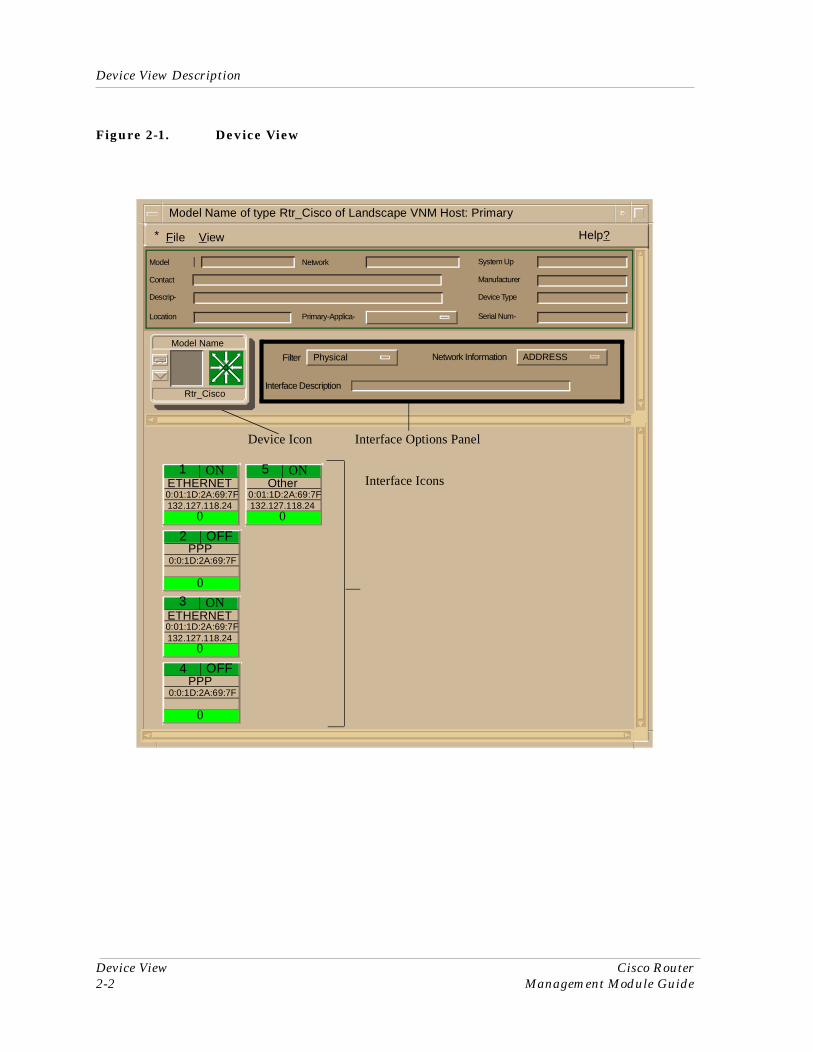
Device View DescriptionThis section describes the Interface icons displayed in the Device view (accessible from the device icon) and the Interface Options panel. This view provides dynamic configuration and performance information for each interface on this device. If the configuration changes, SPECTRUM modifies the Device view after the next polling cycle to reflect the new configuration. This view also provides a Device icon which allows you to monitor the device operation and access other device-specific views. Figure 2-1 shows a typical Cisco Router Device view.
Device View Description
Device View Cisco Router2-2 Management Module Guide
Figure 2-1. Device View
* File View Help?
Model Name of type Rtr_Cisco of Landscape VNM Host: Primary
Filter
Interface Description
Network Information ADDRESSPhysical
1 ONETHERNET0:01:1D:2A:69:7F
0
Model
Contact
Descrip-
Location
Network System Up
Manufacturer
Device Type
Serial Num-Primary-Applica-
132.127.118.24
Interface Options PanelDevice Icon
Interface Icons
2 OFFPPP
0:0:1D:2A:69:7F
0
3 ONETHERNET0:01:1D:2A:69:7F
0132.127.118.24
4 OFFPPP
0:0:1D:2A:69:7F
0
5 ONOther
0:01:1D:2A:69:7F
0132.127.118.24
Model Name
Rtr_Cisco

9030809 E10 Device View2-3
Device View Description
Interface Icons
Interface Icons
Interface icons represent each port on the Cisco Router. The Interface icon consists of six labels, providing configuration and performance information. Figure 2-2 shows an example of an Interface icon and it’s labels.
Figure 2-2. Interface Icon
Interface Number Label
This label displays the number of this interface. Double-click on this label opens the Cisco Router’s Device Topology (DevTop) view.
1 ONETHERNET
0.0.1D.E.79.F5
0
(a) (b)
(c)(d)(e)(f)
CloseNavigateAlarmsPerformanceNotes...UtilitiesDevTopPerformance (Filter)DetailIF StatusIFConfiguration IF Address Translation TableNetwork Information PanelThresholdsModel Information
Ctrl+c
a. Interface Number Label/Device Topology View
b. IF Status Label/Interface Status View
c. Interface Type Label/Interface Configuration - Interface View
d. Physical Address Label/IF Address Translation Table Label
e. IP Address Label/Network Information
f. Gauge Label/Performance View

Device View Description
Device View Cisco Router2-4 Management Module Guide
IF Status Label
This label displays the operational status and background color to represent the current status of the interface. Table 2-1 shows the possible interface statuses and their respective colors.
Double-clicking on this IF Status View label accesses the Interface Status View, which provides the following information on the status of the interface:
Operational StatusThis field displays the current operational state of the interface (ON, OFF, or Testing).
This button allows you to select the desired operational state of the interface (ON, OFF, or Testing).
Interface Type Label
This label displays the type of interface on this port. Example: Other, Ethernet, FDDI, etc. Double-click this label to access the Interface Configuration- Interface View described on Page 3-9.
Physical Address Label
This label displays the physical address of the Cisco Router interface. Double-click the Physical Address Label to open the Interface Address Translation Table. This table cross-references device IP addresses to device MAC (Ethernet) addresses for selected nodes between networks. Double-clicking on any column entry opens an address-specific Address Translation Table Information View. This view provides the same information as the
Table 2-1. Interface Status Label Definitions
Operational Status Administrative Status Text Display Color
ON ON ON Green
OFF OFF OFF Blue
OFF ON OFF Yellow
Testing Testing Test Red
Administrative Status

9030809 E10 Device View2-5
Device View Description
Interface Options Panel
corresponding row for the IF Address Translation Table, but allows you to modify field values.
IP Address Label
This label displays the IP address for this Interface. Double-click this label to open the Network Information Panel. This panel provides name, network address, and subnet mask information for the interface. Any of the network information entries from this panel can be displayed on this label of the Interface icon.
Gauge Label
This label displays the performance statistic determined by the Gauge Control Panel Described on Page 2-6. Double-click this label to open the Performance view described in the SPECTRUM Views.
Interface Options Panel
This area of the Device view (Figure 2-1) allows you to modify the presentation of a highlighted Interface icon. Double-click a non-text area of this panel to open the Gauge Control Panel, described below. The Interface Options panel provides the following information:
FilterThis menu button allows you to select the application to be displayed by the Interface icons. You can leave the default Physical or select Bridging. You can also select other applications such as IP routing if the SPECTRUM Routing Services Management Module is loaded. For more information, refer to the Routing Services Management Module Guide.
Network InformationThis menu button allows you to select the type of information displayed in the Network Information label of the highlighted Interface icon. Possible selections are ADDRESS, NAME, or MASK.
Interface DescriptionThis field provides a description of the interface. If no Interface icon is highlighted, this field is empty.

Device View Description
Gauge Control Panel
Device View Cisco Router2-6 Management Module Guide
Gauge Control Panel
This panel (Figure 2-3) allows you to change the type of statistical information displayed on the Gauge label of the Interface icon. To access the Gauge Control Panel, double-click the background of the Interface Options panel or do the following:
1. Highlight the Interface Options panel.
2. From the Icon Subviews menu, select Gauge Control Panel.
Figure 2-3. Gauge Control Panel
The Gauge Control Panel provides the following:
• Gauge Mode• Selected Attribute• Gauge Type• Gauge Buttons
Gauge ModeThis area allows you to select the type of information shown on the Gauge Label of the Interface icon: Rates, Totals, or Percentages. The Percentages selection displays the percentage of the selected interface compared to the rest of the interfaces.
Gauge Buttons
Gauge Mode Selected Attribute
Rates LoadTotals Load InPercentages Load Out
Packet RateGauge Type In Packet Rate
Out Packet RateNumeric % DiscardLinear % Filtered
Gauge Control Panel
Apply Keep Settings
Reset Close
Default

9030809 E10 Device View2-7
Device View Description
Gauge Control Panel
The color displayed on the Gauge Label depends upon the particular mode and statistical attribute selected. Table 2-2 and Table 2-3 list the attributes and their corresponding colors for the Rates mode and Totals mode, respectively.
Table 2-2. Rate Gauge Mode: Attributes and Corresponding Color
Selected Attribute Color
Load Green
Load In Green
Load Out Green
Packet Rate Blue
In Packet Rate Blue
Out Packet Rate Blue
% Discard Tan
% Filtered Gray
% Forwarded Violet
% Host Bound Yellow
% Error Orange
% Transmitted White
Table 2-3. Totals Gauge Mode: Attributes and Corresponding Color
Selected Attribute Color
Errors Orange
In Packets Blue
Out Packets Blue
In Octets Green
Out Octets Green
Discards Tan
Forwarded Purple
Host Bound Yellow
Transmitted White
Filtered Gray

Device View Description
Device View Cisco Router2-8 Management Module Guide
Selected AttributeThis area allows you to select the statistical attribute displayed on the Interface icon’s Gauge label. The label changes color to reflect the attribute selected.
Gauge TypeThis option allows you to select either a numeric or linear display on the Gauge label.
Gauge ButtonsThe following describes the Gauge buttons:
Applies the current settings to the Gauge label temporarily but does not save the settings.
Saves the current settings while using SpectroGRAPH. Settings return to default when you restart SpectroGRAPH.
Returns the settings to the previously saved values.
Closes the Gauge Control Panel.
Returns the settings to the SPECTRUM default.
Apply
Keep Settings
Reset
Close
Default

9030809 E103-1
Chapter 3
Configuration Views
What is in This ChapterThis chapter describes the Configuration views available for the Cisco Router. These views display network configuration information. These Configuration views apply to all Cisco Router model types. The following Configuration views are described in this chapter:
• Cisco Router Configuration View• Interface Configuration- Interface View
See Chapter 1, Introduction, for information on Accessing SPECTRUM Views.
Cisco Router Configuration ViewThe Configuration view for the Cisco Router provides detailed information on the Cisco Router’s network, host, port, and model configuration.
Primary AddressThe IP Address for the device being modeled.
Device NameThe user-defined or default name of the model.
Contact StatusThe status of the Cisco Router. Possible values are Established, Lost, or Initial.
Number of InterfacesThe number of ports on the Cisco Router.

Cisco Router Configuration View
Configuration Views Cisco Router3-2 Management Module Guide
This button opens the Router Redundancy/Discovery Control View. This view is described later in this chapter.
Firmware RevisionThe firmware version of the Cisco Router.
Why Last ReloadAn ASCII text string explaining why the system was last restarted.
Authentication FailThe IP address of the last SNMP authorization failure.
The Interface Address Translation button accesses the Interface Address Translation Table. This view is described later in this chapter.
This button allows you to access the Cisco Buffer Management View, which provides data information for network traffic to the Cisco Router. It counts IP Packets received and tracks activity for the various Cisco Router buffers. The Cisco Buffer Management View is described in the section titled Cisco Buffer Management View later in this chapter.
Boot HostThe IP address of the host that provided the currently running software.
Domain NameAn ASCII text string displaying the domain portion of the domain name of the host.
Host NameAn ASCII text string displaying the name of the host.
This button accesses the Cisco Network/Host Configuration View. The fields are described below.
NetConfig File Host AddressThe IP address of the host that provided the network configuration file.
NetConfig file NameThe name of the network configuration file.
Load New NetConfig FileThis field permits the loading of a new network configuration file using TFTP.
Host Config File Host AddressThe IP address of the host that provided the host configuration file.
Discover/Reconfigure Control
IF Address Translation
Buffer Management
Network/Host Config

9030809 E10 Configuration Views3-3
Cisco Router Configuration View
Host Config FileThe name of the host configuration file.
Load New Host Config FileThis field permits the loading of a new host configuration file using TFTP.
Interface Configuration Table The Interface Configuration Table in the bottom half of the Cisco Router Configuration View provides port configuration information for each of the Cisco Router’s ports.
IndexThe port number on the Cisco Router.
DescriptionA textual description of the interface, which may include the name of the manufacturer, the product name and version number of the hardware interface.
TypeThe type of interface for the port. Possible interface types and a brief description of each type are shown in Table 7-8.
BandwidthThe estimated bandwidth of the interface measured in bits per second. For interfaces that do not vary in bandwidth or for which no accurate estimate can be made, a nominal bandwidth is provided.
Physical AddressThe Ethernet (MAC) address of the port.
Operation StatusThe current operational state of the port (On, Off, or Testing).
Admin StatusThe desired operational state of the port (On, Off, or Testing).
Last ChangeThe System UpTime value when the port entered its current operational state.
Change ReasonAn ASCII text string explaining why the system was last restarted.
Queue LengthThe length of the outbound packet queue in packets.
Packet SizeThe largest Maximum Transmission Unit (MTU) that can be transmitted or received by the port measured in octets.

Cisco Router Configuration View
Configuration Views Cisco Router3-4 Management Module Guide
Router Redundancy/Discovery Control
This functionality allows you to select whether the device will automatically discover when a reconfiguration takes place. The fields are described below.
Primary AddressShows the IP address for this device.
If SPECTRUM is unable to contact the router through the IP address initially assigned to it (Primary Address), the router’s icon turns yellow, and SPECTRUM attempts to reach the router via the ports on the device’s Preferred Address list, until contact is made. SPECTRUM then uses that IP address to obtain network management information from the router until the Primary Address becomes available again. When contact is re-established through the Primary Address, the icon turns green. If SPECTRUM is unable to make contact via any of the Preferred Addresses, the router’s icon turns red, denoting that contact has been lost with the physical device.
Router RedundancyEnables SPECTRUM to contact the Cisco Router through an alternate port in the event of a primary (address) port failure. Choices are On or Off.
Discover after ReconfigurationSPECTRUM attempts to discover routing connections for this device only. The default value true indicates that router models are properly mapped to the network database, and the false value indicates database connections to LAN models cannot be completed.
Discovery MoveUpon reconfiguration, if a router discovers any device connections that are incorrect, the router will modify or move the connection to the correct relation. Selecting True allows the model to be moved according to SPECTRUM’s relation rules; selecting False allows the model to remain in the original view.
Selecting Addresses for Router Redundancy
1. Ensure that Router Redundancy is set to On in the Cisco Router Configuration view.
2. Click the Preferred Addresses button in the Cisco Router Configuration view’s banner.

9030809 E10 Configuration Views3-5
Cisco Router Configuration View
The Preferred Addresses window appears. This window lists and numbers the preferred addresses in the order in which SPECTRUM attempts to contact the ports in the event of a Primary Address failure.
3. Make changes as needed:
a. To change the Primary Address, double-click the Primary Address field, type the new primary address, and click OK.
b. To delete a Preferred Address, click the preferred address you want to delete, then click Delete.
c. To add a Preferred Address, click the available address you want to add, then click Add. Click Insert At..., type the position number, and click OK to position the address within the list.
4. To change the position of a Preferred Address:
a. Click the preferred address you want to reposition, click Move, then fill in the position information and click OK.
b. Click Update to save the changes.
c. Click Cancel to exit the Preferred Addresses window.
d. Click Reconfigure Model in the Router Redundancy/Discovery Control View.
This button does a complete re-read of the device and its ports. The VNM information for this router will be updated if any of the port addresses have been changed or removed, or if the port type has been changed.
This button discovers the devices that are connected to the ports for this router. Clicking on this button will create all LANS which are defined for each port.
NOTE
When you first create the router model, all its port addresses are listed in both the Available Interface IP Addresses panel and the Redundancy Preferred Addresses panel. Depending on the topology and configuration of your network, you may wish to delete some of the preferred addresses.
Reconfigure Model
Discover LANs

Cisco Router Configuration View
Configuration Views Cisco Router3-6 Management Module Guide
Interface Address Translation Table
The Interface Address Translation Table cross-references device IP addresses to device MAC addresses for selected nodes between networks. Double-clicking on any column entry opens an address-specific Address Translation Table Information View allowing you to modify each of the three fields for that entry.
Cisco Buffer Management View
You can access the Cisco Buffer Management View by clicking on the Buffer Management button in the Cisco Router Configuration View. This view provides the following information:
Free MemoryThe amount of available memory in bytes.
Buffer FailuresThe number of packets discarded due to no memory. An attempted packet buffer allocation failed.
Buffer No MemoryThe number of buffer creation failures due to no memory.
Max Buffer ElementsThe maximum number of buffer elements the Cisco Router may create.
Buffer Elements
This area of the Buffer Management View displays statistics on buffer “elements” (data structures used to enqueue buffers in multiple output queues). Each attribute is summarized for two intervals: total interval since first poll and rate interval between polls (Delta). The following information is displayed in this section of the Buffer Management View:
Buffer Elements FreeThe number of buffer elements available.
Buffer Element HitsThe number of successful requests for buffer elements.
Buffer Element MissesThe number of unsuccessful requests for buffer elements.
Buffer Element CreatesThe number of new buffer elements created by the Cisco Router.

9030809 E10 Configuration Views3-7
Cisco Router Configuration View
Buffer Management Buttons
The Cisco Buffer Management View provides five buttons that allow you to access additional buffer management information according to buffer size. Each attribute is summarized for the total interval since first poll and the rate interval between polls (Delta).
The Small Buffers button allows you to access the Small Buffer Management View. Table 3-1 provides the information displayed in this view..
The Medium Buffers button allows you to access the Cisco Medium Buffer Management View. Table 3-2 provides the information displayed in this view.
Small Buffers
Table 3-1. Small Buffers View Fields
Field Description
Small Buffer Size The maximum size of a small buffer
Max Small Buffers The maximum number of small buffers the Cisco Router may create.
Small Buffer Total The total number of enqueued small buffers.
Small Buffer Free The number of small buffers available.
Small Buffer Hits The number of successful requests for small buffers.
Small Buffer Misses The number of unsuccessful requests for small buffers.
Small Buffer Creates The number of new small buffers created by the Cisco Router.
Small Buffer Trims The number of small buffers returned to the free buffer pool.
Medium Buffers
Table 3-2. Medium Buffers View Fields
Field Description
Medium Buffer Size The maximum size of a medium buffer.
Max Medium Buffers The maximum number of medium buffers the Cisco Router may create.
Medium Buffer Total The total number of enqueued medium buffers.
Medium Buffer Free The number of medium buffers available.
Medium Buffer Hits The number of successful requests for medium buffers.

Cisco Router Configuration View
Configuration Views Cisco Router3-8 Management Module Guide
The button accesses the Big Buffers View. Table 3-3 provides the information displayed in the Big Buffers View.
The Large Buffers button allows you to access the Cisco Large Buffer Management View. Table 3-4 provides the information displayed in this view.
Medium Buffer Misses The number of unsuccessful requests for medium buffers.
Medium Buffer Creates The number of new medium buffers created by the Cisco Router.
Medium Buffer Trims The number of medium buffers returned to the free buffer pool.
Table 3-2. Medium Buffers View Fields (Continued)
Big Buffers
Table 3-3. Big Buffers View Fields
Field Description
Big Buffer Size The maximum size of a big buffer.
Max Big Buffers The maximum number of big buffers the Cisco Router maycreate.
Big Buffer Total The total number of enqueued big buffers.
Big Buffer Free The number of big buffers available.
Big Buffer Hits The number of successful requests for big buffers.
Big Buffer Misses The number of unsuccessful requests for big buffers.
Big Buffer Creates The number of new big buffers created by the Cisco Router.
Big Buffer Trims The number of big buffers returned to the free buffer pool.
Large Buffers
Table 3-4. Large Buffers View Fields
Field Description
Large Buffer Size The maximum number of bytes in a large buffer.
Max Large Buffers The maximum number of large buffers the Cisco Router may create.
Large Buffer Total The total number of enqueued large buffers.
Large Buffer Free The number of large buffers available.
9030809 E10 Configuration Views3-9
Interface Configuration- Interface View
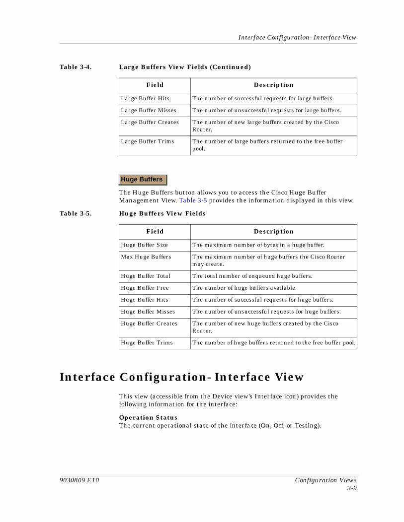
The Huge Buffers button allows you to access the Cisco Huge Buffer Management View. Table 3-5 provides the information displayed in this view.
Interface Configuration- Interface ViewThis view (accessible from the Device view’s Interface icon) provides the following information for the interface:
Operation StatusThe current operational state of the interface (On, Off, or Testing).
Large Buffer Hits The number of successful requests for large buffers.
Large Buffer Misses The number of unsuccessful requests for large buffers.
Large Buffer Creates The number of new large buffers created by the Cisco Router.
Large Buffer Trims The number of large buffers returned to the free buffer pool.
Table 3-4. Large Buffers View Fields (Continued)
Field Description
Huge Buffers
Table 3-5. Huge Buffers View Fields
Field Description
Huge Buffer Size The maximum number of bytes in a huge buffer.
Max Huge Buffers The maximum number of huge buffers the Cisco Router may create.
Huge Buffer Total The total number of enqueued huge buffers.
Huge Buffer Free The number of huge buffers available.
Huge Buffer Hits The number of successful requests for huge buffers.
Huge Buffer Misses The number of unsuccessful requests for huge buffers.
Huge Buffer Creates The number of new huge buffers created by the Cisco Router.
Huge Buffer Trims The number of huge buffers returned to the free buffer pool.
Interface Configuration- Interface View
Configuration Views Cisco Router3-10 Management Module Guide
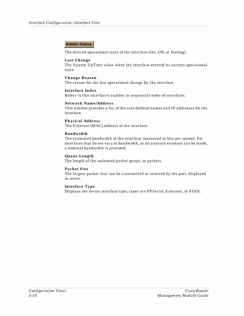
The desired operational state of the interface (On, Off, or Testing).
Last ChangeThe System UpTime value when the interface entered its current operational state.
Change ReasonThe reason for the last operational change for the interface.
Interface IndexRefers to this interface’s number in sequential order of interfaces.
Network Name/AddressThis window provides a list of the user-defined names and IP addresses for the interface.
Physical AddressThe Ethernet (MAC) address of the interface.
BandwidthThe estimated bandwidth of the interface, measured in bits per second. For interfaces that do not vary in bandwidth, or no accurate estimate can be made, a nominal bandwidth is provided.
Queue LengthThe length of the outbound packet queue, in packets.
Packet SizeThe largest packet that can be transmitted or received by the port, displayed in octets.
Interface TypeDisplays the device interface type; types are PPSerial, Ethernet, or FDDI.
Admin Status

Ctron Part No. Here4-1
Chapter 4
Event and Alarm Messages
What is in This ChapterThis chapter describes the events and alarms generated by the Cisco Router and provides any corresponding probable cause messages.
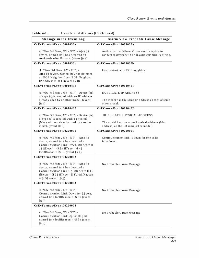
Cisco Router Events and AlarmsTable 4-1 lists the events and alarms supported by the Cisco Router.
Table 4-1. Events and Alarms
Message in the Event Log Alarm View Probable Cause Message
CsEvFormat/Event00010002
{d “%w- %d %m-, %y - %T”} - A Cisco Router, {t} (name - {m}) has been reloaded. SystemUpTime = {I 1}. (Trap type : 0x10002) - (event [{e}])
No Probable Cause Message
CsEvFormat/Event00010003
{d “%w- %d %m-, %y - %T”} - A Cisco Router, {t} (name - {m} has reported the end of a TCP session. tcpConnEntry = {0 1}. sessionType = {I 2}. loctcpConnInBytes = {I 3}. loctcpConnOutBytes = {I 4}. ElapsedTime = {I 5} time ticks. (Trap type : 0x1003) - (event [{e}])
No Probable Cause Message

Cisco Router Events and Alarms
Event and Alarm Messages Book Title Top4-2 Book Title Bottom
CsEvFormat/Event00010004 CsEvFormat/Event00010306
{d “%w- %d %m-, %y - %T”} - A Cisco Router, {t} (name - {m}) has reported an X.25 related trap. (Trap type : 0x10002) - (event [{e}])
No Probable Cause Message
CsEvFormat/Event00010013 CsEvFormat/Event00010307
{d “%w- %d %m-, %Y - %T”} - A(n) {t} device, named {m}, has been cold started. System UpTime = {I 1}. (event [{e}])
No Probable Cause Message
CsEvFormat/Event00010014
{d “%w- %d %m-, %Y - %T”} - A(n) {t} device, named {m}, has been warm started. System UpTime = {I 1}. (event [{e}])
No Probable Cause Message
CsEvFormat/Event00010017
{d “%w- %d %m-, %Y - %T”} - A(n) {t} device, named {m}, has detected an Authentication Failure. (event [{e}])
CsPCause/Prob0001030a
Authorization failure. Other user is trying to connect to device with an invalid community string.
CsEvFormat/Event00010018
{d “%w- %d %m-, %Y - %T”} - A(n) {t} device, named {m}, has detected an EGP Neighbor Loss. egpNeighAddr = {0 1} (event [{e}])
CsPCause/Prob0001030b
Lost contact with EGP neighbor.
CsEvFormat/Event00010203
{d “%w- %d %m-, %Y - %T”} - The model created is not the same type as the device. Model type = {t}, Name = {m}, User = {u}. (event [{e}])
CsPCause/Prob00010203
The model created is not the same type as the device.
CsEvFormat/Event00010308
{d “%w- %d %m-, %Y - %T”} - A(n) {t} device, named {m}, has detected a communication Link Down. (event [{e}])
CsPCause/Prob00010308
Communication link is down.
CsEvFormat/Event00010309
{d “%w- %d %m-, %Y - %T”} - A(n) {t} device, named {m}, has detected a communication Link Up. (event [{e}])
No Probable Cause Message
Table 4-1. Events and Alarms (Continued)
Message in the Event Log Alarm View Probable Cause Message
Ctron Part No. Here Event and Alarm Messages4-3
Cisco Router Events and Alarms
CsEvFormat/Event0001030a
{d “%w- %d %m-, %Y - %T”} - A(n) {t} device, named {m}, has detected an Authentication Failure. (event [{e}])
CsPCause/Prob0001030a
Authorization failure. Other user is trying to connect to device with an invalid community string.
CsEvFormat/Event0001030b
{d “%w- %d %m-, %Y - %T”} - A(n) {t} device, named {m}, has detected an EGP Neighbor Loss. EGP Neighbor IP address is {0 1}.(event [{e}])
CsPCause/Prob0001030b
Lost contact with EGP neighbor.
CsEvFormat/Event00010401
{d “%w- %d %m-, %Y - %T”} - Device {m} of type {t} is created with an IP address already used by another model. (event [{e}])
CsPCause/Prob00010401
DUPLICATE IP ADDRESS
The model has the same IP address as that of some other model.
CsEvFormat/Event00010402
{d “%w- %d %m-, %Y - %T”} - Device {m} of type {t} is created with a physical (Mac) address already used by another model. (event [{e}])
CsPCause/Prob00010402
DUPLICATE PHYSICAL ADDRESS
The model has the same Physical address (Mac address) as that of some other model.
CsEvFormat/Event00220001
{d “%w- %d %m-, %Y - %T”} - A(n) {t} device, named {m}, has detected a Communication Link Down. ifIndex = {I 1}. ifDescr = {S 3}. ifType = {I 4}. locIfReason = {S 5}. (event [{e}])
CsPCause/Prob00220001
Communication link is down for one of its interfaces.
CsEvFormat/Event00220002
{d “%w- %d %m-, %Y - %T”} - A(n) {t} device, named {m}, has detected a Communication Link Up. ifIndex = {I 1}. ifDescr = {S 3}. ifType = {I 4}. locIfReason = {S 5}. (event [{e}])
No Probable Cause Message
CsEvFormat/Event00220003
{d “%w- %d %m-, %Y - %T”} - Communication Link Down for {t} port, named {m}, locIfReason = {S 5}. (event [{e}])
No Probable Cause Message
CsEvFormat/Event00220004
{d “%w- %d %m-, %Y - %T”} - Communication Link Up for {t} port, named {m}, locIfReason = {S 5}. (event [{e}])
No Probable Cause Message
Table 4-1. Events and Alarms (Continued)
Message in the Event Log Alarm View Probable Cause Message

Cisco Router Events and Alarms
Event and Alarm Messages Book Title Top4-4 Book Title Bottom

9030809 E105-1
Chapter 5
Application View
What Is in This ChapterThis chapter describes the following device-specific applications for the Cisco Routers:
• Routing Application• Cisco FDDI Application• Cisco Flash Application• Cisco Chassis Application• Cisco Channel Application• DSPU Application• Terminal Server Application• MIB-II Application• Frame Relay Application• Cisco Ping Application• Cisco Queue Application• IF Application• Cisco Environment
The Application view allows you to access increasingly detailed views of network information for the applications supported by this device.

Common Applications
Application View Cisco Router5-2 Management Module Guide
Common ApplicationsThese devices support the following common applications :
• Bridging (CSIBridge)- Enet SDB (Ct_BdgEnet_App)- PPP_Bridge (PPP_BdgApp1474)- Spanning Tree (Ct_Stp_App)- Static (Static_App)- Transparent (Transparnt_App)
• MIB-II (SNMP2_Agent)- ICMP (ICMP_App)- IP (IP2_App)- System (System2_App)- UDP (UDP2_App)
• PPP (PPP_LCPApp1471)• RS-232 (CtWANAppRS232)• RS-232sync (RFC1317sync)• WAN (CtWANApp)• DS1 (CtWANAppDS1)• Frame Relay (rfc1315App)
Device Application View This view shows the common and device-specific applications supported by this device and provides access to application-specific information.
See Chapter 1,Introduction, for information on Accessing SPECTRUM Views.
Figure 5-1 shows an example of an Application view in the Icon mode. Figure 5-2 shows an example of an Application view in the List mode.
To change the display mode, select View -> Mode -> List or Icon.

9030809 E10 Application View5-3
Device Application View
Figure 5-1. Device Application View (Icon Mode)
* File View Help?
Model Name of type Rtr_Cisco of LandscapeVNMHost: Primary
Model Name
Contact
Description
Location
Net Addr
Prime-App
Sys Up Time
Manufacturer
Device Type
Serial Number
9T425_16
Model Name
Novell
CiscoNovellApp
Bridging
MIB-II
SNMP2_Agent
ICMP
ICMP_App
IP
IP2_App
System
System2_App
UDP
UDP2_App
SNMP2_Agent
ICMP_App
IP2_App
System2_App
UDP2_App
CiscoPing
CiscoPingApp
CiscoPingApp
CiscoQueueCiscoFlashApp
CiscoFlashApp
CiscoFlashApp
Model Name
Rtr_Cisco
AppleTalk
AppltlkRtrApp
Routing
GenRtrApp
IPRouting
CiscoIPApp
XNS
CiscoXNsApp
CiscoQueue
CiscoQueueApp

Device Application View
Application View Cisco Router5-4 Management Module Guide
Figure 5-2. Device Application View (List Mode)
* File View Help?
Model Name of type Rtr_Cisco of Landscape VNM Host: Primary
Model Name
Contact
Description
Location
Net Addr
Prime-App
Sys Up Time
Manufacturer
Device Type
Serial NumberBridging
Rtr_Cisco
SNMP2_Agent
ICMP_App
IP2_App
System2_App
UDP2_App
GenRtrAppCisco IP App
CiscoXNSApp
CiscoNovellApp
ApplTlkRtrApp
CiscoChasApp
CiscoFlashApp
CiscoPingApp
CiscoQueueApp
CiscoCDPApp
Cisco BSTUNApp
CiscoSTUNApp
Gen_Bridge_App
Static_App
EthernetApp
EthernetIFApp

9030809 E10 Application View5-5
Routing Application
Routing ApplicationTable 5-1 provides a list of the supported routing applications, their model type names, and the views available for each application. The model type appears on the label on the Application view icon.
Cisco Generic Routing Application
The Cisco Generic Routing application supports the Routing Protocol Comparison view in addition to the Performance View described earlier in this chapter. The Routing Protocol Comparison View shows the same statistical
Table 5-1. Routing Application Model Type Names
Application Model Type Additional View(s)
Cisco Generic Routing Application
CiscoGenRtrApp Routing Protocol Comparison
AppleTalk Routing Application
ApplTlkRtrApp RTMP TableKinetics Internet Protocol TableName Binding Protocol TableZone Information TableLocalTalk Interface TableAppleTalk Port TableAppleTalk ARP TableAppleTalk Echo View
DECnet Routing Application
CiscoDNApp Host TableArea TableInterface Cost TableDECnet Routing Level 1 ViewDECnet Routing Level 2 ViewDECnet Routing Hello View
IP Routing Application CiscoIPApp IP Configuration IP Routing TableIP Address TableIP Fragmentation IP Reassembles Cisco IP Accounting Table
Novell Routing Application
CiscoNovellApp Novell SAP Novell IPX (may or may not be supported)
Vines Routing Application CiscoVinesApp Vines Routing Echo Vines Routing ICP Vines Broadcast Detail Vines Rx Vines Tx
XNS Routing Application CiscoXNSApp XNS Routing Echo
Routing Application
AppleTalk Routing Application
Application View Cisco Router5-6 Management Module Guide
information as seen in this application’s Detail View. Refer to the Operator’s Bridging Applications, MIB-II Applications, or Miscellaneous Applications documentation for descriptions of Performance and Detail views .
Routing Protocol Comparison View
This view displays pie charts with performance statistics for each GenRtrApp sub-application.
AppleTalk Routing Application
There are eight additional application-specific sub-views available for the AppleTalk Routing (ApplTlkRtrApp) application as follows:
• RTMP Table• KIP Table• Name Binding Protocol Table• ZIP Table• LLAP Table• ATPORT Table• ARP Table• Echo View
Each of these tables or views are described below.
RTMP Table
This table includes the routing information for the Routing Table Management Protocol Table. This view provides the following:
RTMP HopsThe number of hops required to reach the destination network for this entry.
RTMP Next HopThe IP address of the next hop in the route to this entry’s destination network.
RTMP Type The type of this network entry.
RTMP StateThe state of this network entry.
Start Net.NodeThe first AppleTalk network address in the range for this routing entry. This address is a two octet DDP network address in network byte order.

9030809 E10 Application View5-7
Routing Application
AppleTalk Routing Application
END Net.Node The last AppleTalk network address in the range for this routing entry. This address is a two octet DDP network address in network byte order.
RTMP Port The network address configured for this port.
KIP Table
This table includes the routing information for the Kinetics Internet Protocol Table. This view provides the following:
Kip Broadcast AddThe form of the IP address used to broadcast on this network.
Kip Next HopThe IP address of the next hop in the route to this entry’s destination network.
Kip Type The type of this network entry.
Kip StateThe state of this network entry.
Kip Net StartThe first AppleTalk network address in the range for this routing entry. This address is a two octet DDP network address in network byte order.
Kip Net EndThe last AppleTalk network address in the range for this routing entry. This address is a two octet DDP network address in network byte order.
Kip ShareIf the information in this entry is propagated to other routers as part of a routing protocol, the value of this variable is equal to shared. Otherwise its value is private.
Kip CoreThe status of this network as a Kip Core network.
Kip Hop CountThe number of hops required to reach the destination network for this entry.
Name Binding Protocol Table
The NBP, or Name Binding Protocol Table, represents the table of NBP services registered on this entity. This table can be accessed by clicking on the NBP Table selection of the Icon Subviews menu.

Routing Application
AppleTalk Routing Application
Application View Cisco Router5-8 Management Module Guide
Name Binding IndexThe index of this NBP entry. This value ranges from 1 to the number of NBP entries currently registered on this entity.
Name Binding ObjectThe name of the service described by this entity.
Name Binding TypeThe type of service described by this entity.
Name Binding ZoneThe zone the service described by this entity is registered in.
Name Binding StateThe state of this NBP entry.
ZIP Table
The ZIP, or Zone Information Protocol Table, manages the relationship between network numbers and zone names. ZIP views are identified as the following:
Zone NameThe ASCII zone name for this entry.
Zone StateThe state of this ZIP entry.
Zone Net StartThe network that starts the range for this entry. This address is a two octet DDP network address in network byte order.
Zone Net EndThe network that ends the range for this entry. This address is a two octet DDP network address in network byte order. If the network to which this zip entry pertains is a Phase 1 network or a non-extended network, the value for Zone Net End shall be two bytes of zero.
Zone IndexAn integer that is unique to the Zone Name that is present in this entry. For any given zone name, every entry that has an equal Zone Name will have the same Zone Index.
LLAP Table
The LLAP, or LocalTalk Link Access Protocol, appears as the LocalTalk Interface Table in the LLAP View. The list of LLAP entries follows:

9030809 E10 Application View5-9
Routing Application
AppleTalk Routing Application
Interface IndexThe LLAP interface to which this entry pertains.
In PacketsThe total number of good packets received on this LocalTalk interface.
Out PacketsThe total number of packets transmitted on this LocalTalk interface.
No HandlerThe total number of good packets received on this LocalTalk interface for which there was no protocol handler.
Length ErrorsThe total number of packets received on this LocalTalk interface whose actual length did not match the length in the header.
Total In ErrorsThe total number of packets containing errors received on this LocalTalk interface.
Total CollisionThe total number of collisions assumed on this LocalTalk interface due to the lack of a lapCTS reply.
Total DeferThe total number of times this LocalTalk interface deferred to other packets.
No Data ErrorsThe total number of times this LocalTalk interface received a lapRTS packet and expected a data packet, but did not receive any data packet.
Random CTS ErrorsThe total number of times this LocalTalk interface received a lapCTS packet that was not solicited by a lapRTS packet.
FCS ErrorsThe total number of times this LocalTalk interface received a packet with an FCS (Frame Check Sequence) error.
ATPORT Table
The ATPORT, or AppleTalk Port Table, contains a list of AppleTalk ports for this entity. The entries for this category are as follows:
Port IndexA unique value for each AppleTalk port. Its value is between 1 and the total number of AppleTalk ports. The value for each port must remain constant at least from the re-initialization of the entity’s network management system to the next re-initialization.

Routing Application
AppleTalk Routing Application
Application View Cisco Router5-10 Management Module Guide
Port DescriptionA text string containing printable ASCII characters providing information about the port..
Port TypeThe type of port, distinguished by the protocol immediately below DDP in the protocol stack.
Start Net.NodeThe first AppleTalk network address in the range configured for this port. This is a two octet DDP network address in network byte order.
End Net.NodeThe last AppleTalk network address in the range configured for this port.
Port Net AddressThe network address configured for this port.
Port StatusThe configuration status of this port.
Port Net ConfigThe network configuration for this port.
Port Zone ConfigThe configuration status of the zone information for this port.
Port ZoneThe port zone configured for this AppleTalk port.
Port If IndexThe physical interface associated with this AppleTalk port.
ARP Table
The ARP, or AppleTalk Address Resolution Table, contains an equivalence of AppleTalk Network Address to the link layer physical address. The ARP entries are defined as follows:
ARP Interface IndexThe interface on which this entry’s equivalence is effective.
ARP Physical AddressThe media-dependent physical address.
ARP Network AddressThe AppleTalk Network Address corresponding to the media-dependent physical address.

9030809 E10 Application View5-11
Routing Application
AppleTalk Routing Application
Echo View
The Echo View, or AppleTalk Echo View, is supported by the Appletalk App application. It consists of a single AppleTalk Echo Packets pie chart. Table 5-2 offers the following information on the Echo View:
AppleTalk Routing Table View
This view is available from the Cisco AppleTalk (CiscoATApp) application. You can access the AppleTalk Routing Table view by double-clicking the application-specific view label on the CiscoATApp icon or by selecting AT Protocol Stats from the Icon Subviews menu. This view provides AppleTalk information described in the next section.
RTMP ReceivesThe total number of AppleTalk Routing Table Management Protocol (RTMP) packets received.
RTMP SentThe total number of AppleTalk RTMP packets transmitted.
NBP ReceivesThe total number of AppleTalk Name Binding Protocol (NBP) packets received.
NBP SentThe total number of AppleTalk NBP packets transmitted.
ATP ReceivesThe total number of AppleTalk Transaction Protocol (ATP) packets received.
DDP ShortThe total number of short AppleTalk Datagram Delivery Protocol (DDP) packets received.
DDP LongThe total number of long AppleTalk DDP packets received.
Table 5-2. AppleTalk Echo Packets
Statistic Definition %
Requests The number of AppleTalk Echo packets from a network device to which it transmitted an Echo Request.
% of total Packets
Replies The number of AppleTalk Echo packets from a network device to which it transmitted an Echo reply.
% of total Packets

Routing Application
AppleTalk Routing Application
Application View Cisco Router5-12 Management Module Guide
DDP BadThe total number of illegally sized AppleTalk DDP packets received. The actual packet size and claimed packet size are different.
ZIP ReceivedThe total number of AppleTalk Zone Information Protocol (ZIP) packets received.
ZIP SentThe total number of AppleTalk ZIP packets transmitted.
Echo ReceivesThe total number of AppleTalk Echo packets received.
Illegal EchosThe total number of illegal AppleTalk Echo packets received.
ARP RepliesThe total number of AppleTalk Address Resolution Protocol (ARP) reply packets transmitted.
ARP RequestThe total number of AppleTalk ARP request packets received.
ARP ProbeThe total number of AppleTalk ARP probe packets received.
AppleTalk Routing Detail View
This view provides three color-coded pie charts, which display the AppleTalk routing statistical information displayed by each pie chart. The GenRtrApp Icon Subviews menu choice Generic Routing Detailed Protocol Comparison view also describes these statistics in each of five pie charts.
Table 5-3. Packet Breakdown Pie Chart
Statistic Definition
Forwarded AppleTalk packets forwarded.
Delivered AppleTalk packets delivered to a higher level protocol.
Transmitted AppleTalk packets transmitted.
Errors AppleTalk packets received containing errors.
Discards AppleTalk packets discarded.
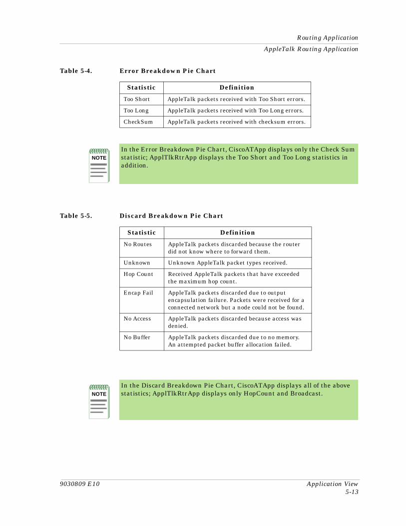
9030809 E10 Application View5-13
Routing Application
AppleTalk Routing Application
Table 5-4. Error Breakdown Pie Chart
Statistic Definition
Too Short AppleTalk packets received with Too Short errors.
Too Long AppleTalk packets received with Too Long errors.
CheckSum AppleTalk packets received with checksum errors.
NOTE
In the Error Breakdown Pie Chart, CiscoATApp displays only the Check Sum statistic; ApplTlkRtrApp displays the Too Short and Too Long statistics in addition.
Table 5-5. Discard Breakdown Pie Chart
Statistic Definition
No Routes AppleTalk packets discarded because the router did not know where to forward them.
Unknown Unknown AppleTalk packet types received.
Hop Count Received AppleTalk packets that have exceeded the maximum hop count.
Encap Fail AppleTalk packets discarded due to output encapsulation failure. Packets were received for a connected network but a node could not be found.
No Access AppleTalk packets discarded because access was denied.
No Buffer AppleTalk packets discarded due to no memory. An attempted packet buffer allocation failed.
NOTE
In the Discard Breakdown Pie Chart, CiscoATApp displays all of the above statistics; ApplTlkRtrApp displays only HopCount and Broadcast.

Routing Application
DECnet Routing Application
Application View Cisco Router5-14 Management Module Guide
DECnet Routing Application
Six additional application-specific subviews are available from the DECnet Routing Application.
• Host Table• Area Table• Interface Cost Table• DECnet Routing Level 1 View• DECnet Routing Level 2 View• DECnet Routing Hello View
Host Table
This table provides the following information:
HostThe DECnet address of the host forwarding DECnet packets.
CostThe aggregate cost to reach the destination node.
HopsThe number of hops to reach the destination node.
InterfaceThe port number of the interface forwarding DECnet packets.
Next HopThe node number of the next node to forward DECnet packets.
AgeThe maximum time a DECnet packet can exist if not forwarded before being discarded.
PriorityThe priority value for determining the default router. The DECnet protocol selects the router with the highest priority value for routing DECnet packets.
Area Table
This table provides the following information:
HostThe DECnet address of the host forwarding DECnet packets.
CostThe aggregate cost to reach the destination area.

9030809 E10 Application View5-15
Routing Application
DECnet Routing Application
HopsThe number of hops to reach the destination area.
InterfaceThe port number of the interface forwarding DECnet packets.
Next HopThe node number of the next node to forward DECnet packets.
AgeThe maximum time a DECnet packet can exist if not forwarded before being discarded.
PriorityThe priority value for determining the default router. The DECnet protocol selects the router with the highest priority value for routing DECnet packets.
Interface Cost Table
This table displays the DECnet circuit cost for each interface. Double-clicking on a column entry allows you to access the entry-specific Interface Cost Table View.
DECnet Routing Level 1 View
This view displays a color-coded pie chart of DECnet Level 1 routing statistics. Table 5-6 provides definitions for the statistics presented by the pie chart.
Table 5-6. DECnet Routing Level 1 Statistics
Statistic Definition
Received The total number of DECnet Level 1 update routing packets received.
Sent The total number of DECnet Level 1 update routing packets transmitted.
Other The total number of DECnet Level 1 routing packets received from another area.
Bad The total number of DECnet Level 1 routing packets received that contained errors.

Routing Application
IP Routing Application
Application View Cisco Router5-16 Management Module Guide
DECnet Routing Level 2 View
This view displays a color-coded pie chart of DECnet Level 2 routing statistics. Table 5-7 provides definitions for the statistics presented by the pie chart.
DECnet Routing Hello View
This view displays a color-coded pie chart of DECnet Hello statistics. Table 5-8 provides definitions for the statistics presented by the pie chart.
IP Routing Application
IP Routing Application, with exception of the IP Accounting Table, is described in detail in Miscellaneous Applications.
Cisco IP Accounting Table View
This table provides information on the amount of network traffic flow between devices and includes a list of IP addresses. Access the Cisco IP Accounting Table as follows:
1. Highlight the IP Routing Application icon.
2. From the Icon Subviews menu, select Accounting.
Table 5-7. DECnet Routing Level 2 Statistics
Statistic Definition
Received The total number of DECnet Level 2 update routing packets received.
Sent The total number of DECnet Level 2 update routing packets transmitted.
Other The total number of DECnet Level 2 routing packets received from another area.
Table 5-8. DECnet Hello Statistics
Statistic Definition
Received The total number of Hellos received.
Sent The total number of Hellos transmitted.
Other The total number of Hellos received from another area.
Bad The total number of Hellos received that contained errors.

9030809 E10 Application View5-17
Routing Application
The IP Accounting Table view provides the following information:
SourceThe source IP address for data transmitted to the destination IP address.
DestinationThe destination IP address for data transmitted from the source IP address.
PacketsThe total number of IP packets transmitted from the source IP address to the destination IP address.
BytesThe total number of bytes transmitted from the source IP address to the destination IP address
This button allows you to access the Cisco Checkpoint Accounting Table, which provides information on the amount of network traffic flow between devices in the checkpoint traffic matrix. Double-clicking on any column entry opens a source IP address to destination IP address-specific checkpoint view. Table 5-9 provides the information contained in the view.
Novell Routing Application
Two additional application-specific subviews are available for the Novell routing application:
• Novell Service Advertisement Protocol (SAP)• Novell Internet Packet Exchange (IPX)
Checkpoint Accounting
Table 5-9. Checkpoint View Information
Field Definition
Source The source IP address for data transmitted to the destination IP address in the checkpoint matrix.
Destination The destination IP address for data transmitted from the source IP address in the checkpoint matrix.
Packets The number of IP packets transmitted from the source IP address to the destination IP address in the checkpoint matrix.
Bytes The total number of bytes transmitted from the source IP address to the destination IP address in the checkpoint matrix.
Routing Application
Novell Routing Application
Application View Cisco Router5-18 Management Module Guide
Novell Service Advertisement Protocol (SAP) View
You can access the Novell Service Advertisement Protocol (SAP) View by double-clicking on the application-specific view label on the CiscoNovellApp Icon or by selecting the SAP/IPX Icon Subviews menu and then selecting SAP Chart from the SAP/IPX submenu. The view is a color-coded pie chart displaying a breakdown of Novell SAP statistics. Table 5-10 provides definitions for the statistics presented by the pie chart.
Novell (IPX) View
This view displays the Check Point Accounting Table, Accounting Table, and additional Check Point Accounting information. The fields are described below.
Check Point Information
Check PointThis field check points the IPX accounting database. This mib variable must be read and then set with the same value for the check point to succeed. The value read and then set will be incremented after a successful set request.
Check Point AgeThis field represents the age of the data in the IPX checkpoint matrix.
IPX Accounting Information
ThresholdThis field represents the threshold of IPX accounting records in use before IPX traffic will be unaccounted.
AgeThis field represents the age of the data in the IPX data matrix.
Table 5-10. Novell SAP Statistics
Statistic Definition
SAP Requests Sent The total number of Novell SAP request packets transmitted.
SAP Replies Sent The total number of Novell SAP reply packets transmitted.
SAP Requests Rec The total number of Novell SAP request packets received.
SAP Responses Rec The total number of Novell SAP reply packets received.

9030809 E10 Application View5-19
Routing Application
Novell Routing Application
Lost BytesThis field represents total bytes of lost IPX packets.
Lost PacketsThis field represents the the lost IPX packets due to memory limitations.
Check Point Accounting Table
This table displays the list of IPX checkpoint accounting entries. The fields for this table are described below.
Source AddressThis field represents the IPX Source address for host traffic matrix.
Destination AddressThis field represents the IPX Destination address for host traffic matrix.
Number PacketsThis field represents the number of IPX packets sent from source to destination.
Number BytesThis field represents the total number of bytes in IPX packets from source to destination.
Accounting Table
This table displays the list of IPX accounting entries. The fields in the Accounting Table are described below.
Source AddressThis field represents the IPX Source address for host in the checkpoint traffic matrix.
Destination AddressThis field represents the IPX Destination address for host in the checkpoint traffic matrix.
Number PacketsThis field represents the number of IPX packets sent from source to destination in the checkpoint matrix.
Number BytesThis field represents the total number of bytes in IPX packets from source to destination in the checkpoint matrix.

Routing Application
Vines Routing Application
Application View Cisco Router5-20 Management Module Guide
Vines Routing Application
Five application-specific subviews are available for the Vines application as follows:
• Vines Routing Echo• ICP• Broadcast Detail• Rx• Tx
Vines Routing Echo View
This view displays a color-coded pie chart displaying a breakdown of Vines Echo statistics. Table 5-11 provides definitions for the statistics presented by the pie chart.
Vines Routing ICP View
This view displays a color-coded pie chart of Vines Interprocess Communications Protocol (ICP) statistics. Table 5-12 provides definitions for the statistics presented by the pie chart.
Table 5-11. Vines Echo Statistics
Statistic Definition
MAC In The total number of Vines MAC level Echo packets received.
MAC Out MAC level Echo packets transmitted.
Echo In The total number of Vines Echo packets received.
Echo Out The total number of Vines Echo packets transmitted.
Table 5-12. Vines ICP Statistics
Statistic Definition
ICP In The total number of Vines ICP packets received.
ICP Out The total number of Vines ICP packets transmitted.
Metric Out The total number of Vines ICP Metric Notification packets transmitted.

9030809 E10 Application View5-21
Routing Application
Vines Routing Application
Vines Broadcast Detail View
This view displays a color-coded pie chart of Vines Broadcast statistics. Table 5-13 provides definitions for the statistics presented by the pie chart.
Vines Rx View
This view provides the following information:
ForwardedThe total number of incoming Vines packets forwarded to another interface.
Format ErrorThe total number of incoming Vines packets containing header errors.
Local DestinationThe total number of incoming Vines packets destined for this router.
Encapsulation TypeThe Vines protocol default encapsulation type.
Echo Count The total number of incoming IPC Echo messages.
Vines Tx View
This view provides the following information:
ForwardedThe total number of outgoing Vines packets forwarded to another interface.
Table 5-13. Vines Broadcast Statistics
Statistic Definition
Forward The total number of Vines broadcast packets forwarded.
Received The total number of Vines broadcast packets received.
Transmitted The total number of Vines broadcast packets transmitted.
Not LAN The total number of Vines broadcast packets not forwarded to all interfaces because the LAN ONLY bit was set.
Not Forward The total number of Vines broadcast packets not forwarded to all interfaces because the OVER 4800 BPS bit was set.
No Charge The total number of Vines broadcast packets not forwarded to all interfaces because the NO CHARGES bit was set.

Cisco FDDI Application
XNS Routing Application
Application View Cisco Router5-22 Management Module Guide
Proxy CountThe total number of Proxy packets sent by this interface.
UnicastsThe total number of unicast packets generated by this interface.
IPC CountThe total number of IPC output messages sent by this interface.
IPC Error CountThe total number of IPC Error messages sent by this interface.
BroadcastsThe total number of broadcast packets generated by this interface.
B-casts ForwardedThe number of broadcasts packets forwarded from another interface.
XNS Routing Application
One application-specific view is available for the XNS routing application. This view displays a color-coded pie chart of XNS Echo statistics. Table 5-14 provides definitions for the statistics presented by the pie chart.
Cisco FDDI Application This section describes the two views available for . Table 5-15 lists the Fiber Distributed Data Interface (FDDI) application supported by the Cisco Router, its model type name, and the views available for the application.
Table 5-14. XNS Echo Statistics
Statistic Definition
Replies Rec The total number of XNS Echo reply packets received.
Replies Sent The total number of XNS Echo reply packets transmitted.
Request Rec The total number of XNS Echo request packets received.
Request Out The total number of XNS Echo request packets transmitted.
Table 5-15. FDDI Application Model Type Names
Application Model Type Name Additional Views
FDDI App CiscoFDDIApp MAC TableSMT Table

9030809 E10 Application View5-23
Cisco FDDI Application
MAC Table
MAC Table
This view provides a table displaying FDDI MAC (Media Access Control) information. A MAC Count field displays the number of MACs on the FDDI ring. The table provides the following information:
SMT IndexThe value of the SMT index associated with this MAC.
MAC IndexA unique value for each MAC on the device. This value must remain constant from one re-initialization of SPECTRUM to the next.
T-ReqThe Target Token Rotation Time (TTRT) bid made by the Cisco Router.
T-NegThe winning TTRT bid on the ring displayed in milliseconds.
T-MaxThe maximum TTRT time interval.
TvxValueThe current value of the TVX counter (transmission time).
T-MinThe minimum TTRT time interval.
Frame_CtThe number of MAC frames.
Error_CtThe number of MAC errors.
Lost_CtThe number of lost MACs.
Chip SetIdentifies the hardware chips principally responsible for the implementation of the MAC function. This object identifier follows IANA conventions. An unknown chip set has a value of 00.
SMT Table
This view provides a table displaying FDDI SMT information. An SMT Count field displays the number of SMTs on the FDDI ring. The table provides the following information:
IndexA unique number identifying each SMT. This value must remain constant from one re-initialization of SPECTRUM to the next.

Cisco Flash Application
Application View Cisco Router5-24 Management Module Guide
Station IDThe code uniquely identifying the FDDI station.
Version IDThe version of SMT the station is using for its operation.
Hi VersionThe highest version of SMT that the station supports.
Low VersionThe lowest version of SMT that the station supports.
StateThe current attachment configuration for the station. Possible values are Isolated, Wrap_S, Wrap_A, Wrap_B, Wrap_AB, and Thru.
Cisco Flash Application Table 5-16 provides the supported Flash application, its model type name, and the application-specific view available for the application. You can access this view through the application icon or text label and the Icon Subviews menu.
The Cisco Flash Configuration View allows you to view changes made to the Cisco Router’s flash memory configuration.
The Cisco Flash Configuration View provides the following information:
Flash Size (Bytes)Total size, in bytes, of flash memory.
Available (Bytes)Unused size, in bytes, of flash memory.
Table 5-16. Cisco Flash Application Model Type Names
Application Model Type Name Additional View
Cisco Flash App CiscoFlashApp Cisco Flash Configuration view
NOTE
The Cisco Flash Configuration view does not allow any downloading or uploading of firmware. All configuration changes must be made from the Cisco Router’s local console. You can use the Cisco Flash Configuration view to view changes made from the local console.

9030809 E10 Application View5-25
Cisco Flash Application
Security JumperThe state of the VPP Dip. This field indicates whether a jumper has been installed on the front of the router to prevent erasure or reprogramming of the flash memory. Possible values are Installed and Missing.
This button allows you to erase the flash memory. Changing this value to Yes will erase the flash memory.
Last Flash Erase TimeThe time that flash memory was last erased.
Flash DirectoryThis table contains a scrolling list of the names of files currently loaded into flash memory, and the size and status of each.
This button displays the Print dialog box. This box allows you to select whether to print to a printer or to a file. If you are printing to a printer, enter the name of the printer and where the output is to be sent. If you are printing to a file, the Select File screen appears displaying the directory and file to which to send the output.
This button opens the Cisco Net To Flash Operation view, which provides information about the last successful firmware download. Table 5-17 lists the information provided by the Cisco Net To Flash Operation View.
This button opens the Cisco Flash To Net Operation View, which provides information about the last successful firmware upload. You can also access this view by double-clicking on an element in the Flash Directory list.
Erase Flash
Net To Flash...
Table 5-17. Cisco Net To Flash Operation View Field Definitions
Field Definition
TFTP Server Network Address The IP address of the host machine containing the firmware to be downloaded.
Server File Name The complete pathname of the firmware to be downloaded.
Last Net -> Flash Copy Time The last time firmware was downloaded into flash memory from the network.
Flash To Net...

Cisco Chassis Application
Application View Cisco Router5-26 Management Module Guide
Table 5-18 lists the information provided by the Cisco Flash To Net Operation View.
Cisco Chassis Application Table 5-19 lists the supported Chassis application, its model type name, and the application-specific views available for the application.
Cisco Chassis Card View
This view displays the Chassis Slot Table, which provides information on the cards contained in the chassis. The table provides the following information:
SlotThe slot number in which this card is installed. If the slot number is not applicable or not determinable, this field will display-1.
TypeThe functional type of the card installed in this slot. The following values are possible types: Unknown, csc1, csc2, csc3, csc4, rp, csc-m, csc-mt, csc-mc, csc-mcplus, csc-envm, csc-16, csc-p, csc-a, csc-e1, csc-e2, csc-y, csc-s, csc-t, sci4s, sci2s2t, sci4t, mci1t, mci2t, mci1s, mci1s1t, mci2s, mci1e, mci1e1t, mci1e2t, mci1e1s, mci1e1s1t, mci1e2s, mci2e, mci2e1t, mci2e2t, mci2e1s, mci2e1s1t, mci2e2s, csc-r, csc-r16, csc-r16m, csc-1r, csc-2r, csc-cctl1, csc-cctl2, csc-mec2, csc-mec4, csc-mec6, csc-fci, csc-fcit, csc-hsci, csc-ctr, sp, eip, fip, hip, sip, trip, fsip, aip, mip, ssp, npm-4000-fddi-sas, npm-4000-fddi-das, npm-4000-1e, npm-4000-1r, npm-4000-2s, npm-4000-2e1, npm-4000-2e, npm-4000-2r1, npm-4000-2r, npm-4000-4t.
Table 5-18. Cisco Flash To Net Operation View Field Definitions
Field Definition
TFTP Server Network Address The IP address of the target network host.
Flash File Name The name of the flash file to be uploaded to the server.
Last Flash -> Net Copy Time The last time firmware was uploaded from flash memory to a network server.
Table 5-19. Cisco Chassis Application Model Type Names
Application Model Type Name Additional Views
Cisco Chassis App CiscoChasApp General Information view Cisco Chassis Card view
9030809 E10 Application View5-27
Cisco Chassis Application
Cisco Chassis General Information View
DescriptionA textual description of this card.
Software Ver.The version number of the firmware installed on this card. If no version number is available, this field will remain empty.
Hardware Ver.The hardware revision level of this card. If no revision level is available, this field will remain empty.
Serial No.The serial number of this card. If no serial number is available, this field will contain a zero.
Cisco Chassis General Information View
This view displays information on the chassis in which the router is installed. This view is divided into the three sections described below.
Chassis Information
This section of the Chassis Card View provides physical information about the chassis. The following information is provided:
Hardware Revision LevelThe version number of the chassis hardware. If the version number is not available, this field will remain empty.
Chassis TypeThe type of chassis. Possible chassis types are Unknown, Multibus, Agsplus, Igs, c2000, c3000, c4000, c7000, cs-500, c7010, c2500, and c4500.
Chassis ID/Serial No.A unique identifier for this chassis. The default value is the serial number of the chassis. If no serial number is available and no alternative ID has been set for the chassis, this field will remain empty.
Number of Chassis SlotsThe number of slots in this chassis model.
ROM Information
This section of the Chassis Card View provides the following information about the ROM installed in the chassis:

Cisco Channel Application
Application View Cisco Router5-28 Management Module Guide
ROM Monitor VersionThe version number of the ROM monitor.
ROM Software VersionThe version number of the ROM system software. If no version number is available, this field will remain empty.
Config RegisterThe current value of the configuration register.
RAM Information
This section of the Chassis Card View provides the following information about the RAM installed in the chassis:
System CPU RAM (bytes)The amount of RAM available to the CPU, displayed in bytes.
Non-volatile RAM Used (bytes)The amount of non-volatile configuration memory in use, displayed in bytes.
Non-volatile RAM Size (bytes)The total size, in bytes, of non-volatile configuration memory.
Cisco Channel Application The Channel application allows you to manage the Channel Interface Processor (CIP) card installed in your Cisco Router. Table 5-20 lists the supported Channel application, its model type name, and application-specific views available for the application.
Cisco Channel View
This view displays the Channel Card Table, which provides general information on the status of the Channel Interface Processor (CIP) card installed in the router. The table provides the following information:
IndexThe index value that identifies this card’s position in the Cisco Card Table.
Table 5-20. Cisco Channel Application Model Type Names
Application Model Type Name Additional View(s)
Cisco Channel App CiscoChanApp Cisco Channel viewCisco Sub Channel view
9030809 E10 Application View5-29
DSPU Application
Cisco Sub Channel View
NameThe configured name for the Channel Interface Processor.
Total MemoryThe total memory on the CIP card.
Free MemoryThe total unused memory currently on the CIP card.
CPU UtilizationThe average of the percentage of time that the processor was active over the last minute.
Cisco Sub Channel View
This view displays the Sub Channel Table, which provides information on each host connection active on the Channel Interface Processor card. The table provides the following information:
IndexThe index value identifying the subchannel being referenced by this entry.
ConnectionsThe number of times a device has been connected to this subchannel.
BusiesThe number of “control unit busy” messages sent to the channel when this device was requested.
Device ErrorsThe number of device-level errors recorded by this subchannel.
System RestartsThe number of times this subchannel has recorded a system reset.
DSPU Application Table 5-21 lists the supported DSPU application, its model type name, and the application-specific view available for the application.
Table 5-21. Cisco DSPU Application Model Type Names
Application Model Type Name Additional View
DSPU CiscoDSPUApp Cisco DSPU Information view

Terminal Server Application
Application View Cisco Router5-30 Management Module Guide
Terminal Server Application Table 5-22 lists the supported application, its model type name, and the application-specific views available for the application.
Cisco Terminal Server Line View
This view displays the Terminal Server Line Table, which provides information on each terminal server line connected to the Cisco Router. The table provides the following information:
StatusThe current state of this line. Possible states are Active and Inactive.
TypeThe type of line. Possible types are Unknown, Console, Terminal, Line-Printer, Virtual-Terminal, and Auxiliary.
AutobaudWhether the line will autobaud
Speed InThe input speed of this line, displayed as a baud rate.
Speed OutThe output speed of this line, displayed as a baud rate.
Flow ControlThe type of flow control in use on this line. Possible flow control types are Unknown, None, Software-Input, Software-Output, Software-Both, Hardware-Input, Hardware-Output, and Hardware-Both.
Modem ControlThe type of modem control in use on this line. Possible modem control types are Unknown, None, Call-In, Call-Out, CTS-Required, RI-IS-CD, and InOut.
LocationThe physical location of this line.
Term TypeThe type of terminal on this line.
Length in LinesLenght, in lines, of the terminal’s screen attached to this line.
Table 5-22. Cisco DSPU Application Model Type Names
Application Model Type Name Additional Views
Terminal Srvr CiscoTSApp Cisco Terminal Server Line viewCisco Terminal Server Session view

9030809 E10 Application View5-31
Terminal Server Application
Cisco Terminal Server Session View
Width in CharWidth, in characters, of the terminal’s screen attached to this line.
Escape CharEscape character used to breakout the active sessions.
Idle Time outThe amount of idle time allowed on this line before the line times out.
Session Time outThe amount of idle time allowed in this session before the session times out.
RotaryThe rotary group number the line belongs to.
# of ConnectionsThe number of times a connection has been made to or from this line.
Current SessionThe current number of sessions in use on this line.
UserTACACS user name, if TACACS is enabled.
NoiseCount of garbage characters received when the line is inactive.
Line NumberThe number (listed in sequential order) for this terminal server line.
Time ActiveThe time, in seconds, since the line was activated.
Cisco Terminal Server Session View
This view displays the TS Session Table, which provides information about each terminal server session connected to the Cisco Router. The table provides the following information:
TypeThe type of this session. Possible types are Unknown, Pad, Stream, Rlogin, Telnet, and TCP.
DirectionThe direction of this session. Possible directions are Unknown, Incoming, and Outgoing.
AddrThe remote host address of the session.
Name The remote host name of the session.

MIB-II Application
Application View Cisco Router5-32 Management Module Guide
StateThe indicator of whether this session is the currently active session. Possible states are Inactive and Active.
IdleTime in seconds that the session has been idle.
LineThe index value that identifies this line.
SessionA second index value that identifies this session.
MIB-II Application This section describes the additional views available for the MIB-II applications supported by the Cisco Router.
EGP Application
One additional application-specific subview is available for the EGP application. You can access the EGP Neighbor View by double-clicking the application-specific view label on the EGP2_App Icon or by highlighting the EGP icon or text label and selecting Neighbor Table from the Icon Subviews menu. The EGP Neighbor View displays information about the device’s relationship with a particular EGP neighbor. Double-clicking on a column entry accesses an EGP Neighbor Table View. This view provides a banner and the same information as the EGP Neighbor View, and allows you to modify the fields.
Neighbor StateThe EGP state of the local system with respect to this entry’s EGP neighbor. Possible states are Idle, Acquisition, Down, Up, and Cease.
Neighbor AddressThe IP Address of this entry’s EGP neighbor.
Auto SystemThe autonomous system of this EGP peer. The value “0” should be specified if the autonomous system number of the EGP neighbor is not yet known.
In MsgsThe number of EGP messages received without error from this EGP peer.
In Errors The number of EGP messages received from this EGP peer that contained errors (e.g., bad EGP checksum).

9030809 E10 Application View5-33
Frame Relay Application
Out Msgs The number of locally generated EGP messages to this EGP peer.
Out Errors The number of locally generated EGP messages not sent to this EGP peer due to resource limitations within an EGP entity.
In Error Msgs The number of EGP-defined error messages received from this EGP peer.
Out Error MsgsThe number of EGP-defined error messages transmitted to this EGP peer.
State UpsThe number of EGP state transitions to the “Up” state with this EGP peer.
State DownsThe number of EGP state transitions from the “Up” state to any other state with this EGP peer.
Interval HellosThe interval, in hundredths of a second, between EGP Hello command retransmissions.
Interval PollsThe interval, in hundredths of a second, between EGP poll command retransmissions.
ModeThe polling mode of this EGP entity, either Passive or Active.
Event TriggerDisplays whether communication with an EGP Neighbor is enabled or disabled (1=Start, 2=Stop).
Frame Relay Application This section describes the three tables available for the rfc1315App (Frame Relay) application supported by the Cisco Router. Table 5-23 provides the supported Frame Relay application, its model type name, and the views available for the application. You can access all of these views through the application icon or text label and the Icon Subviews menu.

Frame Relay Application
rfc1315App Circuit Table
Application View Cisco Router5-34 Management Module Guide
rfc1315App Circuit Table
This table provides information on each virtual circuit connected to each frame relay interface. Double-clicking on a table entry allows you to access the entry-specific Circuit Table View, which provides the same information as the rfc1315 Circuit Table for the selected circuit. This view also provides a “Create Circuit” button that allows you to access the Create a Circuit Entry view. Enter a new IfIndex.DLCI value and an associated circuit state in this view to create a new virtual circuit. The rfc1315App Circuit Table and its corresponding entry-specific views are described in the next section.
IndexThe index value that identifies the interface on which this virtual circuit is layered.
DLCIThe Data Link Connection Identifier that uniquely identifies this virtual circuit.
Rcvd FECNsThe number of frames received from the network indicating forward congestion since this virtual circuit was created.
Rcvd BECNsThe number of frames received from the network indicating backward congestion since this virtual circuit was created.
ThroughputThe average number of Frame Relay Information Field bits transferred per second across a user network interface in one direction over the measurement time interval. If the values of Throughput and Committed Burst are both non-zero, the measurement time interval is equal to the Committed Burst value divided by the throughput value. If both these values are zero, the measurement time interval is equal to the excess burst value divided by the speed of the interface.
StateThe current operational state of this virtual circuit. Possible states are Active and Inactive. Setting the state to Invalid removes this entry from the table.
Table 5-23. FDDI Application Model Type Names
Application Model Type Name Additional Views
Frame Relay rfc1315App rfc1315App Circuit Table
rfc1315App Data Link Connection Management Table
rfc1315App Error Table
9030809 E10 Application View5-35
Frame Relay Application
rfc1315App Data Link Connection Management Table
Frames SentThe total number of frames sent from this virtual circuit since it was created.
Octets SentThe total number of octets sent from this virtual circuit since it was created.
Frames ReceivedThe total number of frames received over this virtual circuit since it was created.
Octets ReceivedThe total number of octets received over this virtual circuit since it was created.
Creation TimeThe System Up Time value at the time this virtual circuit was created.
Last ChangeThe System Up Time value at the time this virtual circuit last experienced a change in its state.
Committed BurstThe maximum amount of data, in bits, that the network agrees to transfer over this virtual circuit under normal conditions during measurement time interval. If the values of Throughput and Committed Burst are both non-zero, the measurement time interval is equal to the Committed Burst value divided by the throughput value. If both these values are zero, the measurement time interval is equal to the excess burst value divided by the speed of the interface.
Excess BurstThe maximum amount of uncommitted data, in bits, that the network will attempt to deliver over the measurement time interval. If the values of Throughput and Committed Burst are both non-zero, the measurement time interval is equal to the Committed Burst value divided by the throughput value. If both these values are zero, the measurement time interval is equal to the excess burst value divided by the speed of the interface.
rfc1315App Data Link Connection Management Table
This table provides the parameters for the Data Link Connection Management (DLCM) interface for the frame relay service on this interface. Double-clicking on a table entry allows you to access the entry-specific Data Link Connection Management Table View, which provides the same information as the rfc1315App DLCM Table for the selected table entry. The rfc1315App DLCM Table and its corresponding entry-specific views provide the following information:
IndexThe index value that identifies this frame relay interface.
Frame Relay Application
rfc1315App Error Table
Application View Cisco Router5-36 Management Module Guide
Polling IntervalThe time interval, in seconds, between status enquiry messages sent to this frame relay interface.
Enquiry IntervalThe number of polling intervals that pass before a full status enquiry message is issued to this frame relay interface.
Error ThresholdThe maximum number of unanswered status enquiries SPECTRUM will accept within a given timeframe before declaring the interface down. The error threshold timeframe is specified by the Monitored Events field.
Monitored EventsThe number of polling intervals over which the error threshold is counted.
Max Supported VCsThe maximum number of Virtual Circuits (VCs) allowed for this interface. This value is usually dictated by the Frame Relay network.
StateThe currently active DLCM scheme on this frame relay interface. Possible states are NoLmiConfigured, LmiRev1, AnsiT1-617-D, and AnsiT1-617-B.
Address FormatThe address format currently in use on this frame relay interface. Possible formats are q921, q922March90, q922November90, and q922.
Address LengthThe length of the address, displayed in octets. If the q922 address format is in use, the address length includes the control portion of the address. Possible lengths are Two, Three, and Four.
MulticastAn indication of whether this frame relay interface is using a Multicast service. Possible options are NonBroadcast, and Broadcast. This value is labelled “Broadcast” in the entry-specific DLCM Table View.
rfc1315App Error Table
This table provides descriptions of each error encountered on each frame relay interface. Double-clicking on a table entry allows you to access the entry-specific Error Table View, which provides the same information as the rfc1315App Error Table for the selected table entry. The rfc1315App Error Table and its corresponding entry-specific views provide the following information:
IndexThe index value that identifies this frame relay interface.

9030809 E10 Application View5-37
Frame Relay Application
Discovery Application
Last ErrorThe type of error that was most recently seen on this interface. Possible error types are Unknown, ReceiveShort, ReceiveLong, IllegalDLCI, UnknownDLCI, DlcmiProtoErr, DlcmiUnknownIE, DlcmiSequenceErr, DlcmiUnknownRpt, and DlcmiSinceReset.
Error PacketAn octet string containing as much of the error packet as possible. This packet should contain the q922 address, or as much as was delivered, and may include all packet information up to the PDU.
Time DetectedThe System Up Time Value at the time the error was detected.
Discovery Application
Table 5-24 lists the Icon Subviews menu selections available for the Discovery Application.
Discovery Cache Table View
This view provides the information recieved by the Cisco Discovery Protocol (CDP). It provides the following information:
TypeDisplays the type of address contained in the corresponding Address field described below.
AddressDisplays the network layer of the device’s SNMP-agent as reported in the most recent CDP message.
Device IDDisplays the Device-ID. A zero indicates no Device-ID was reported.
Table 5-24. Catalyst Stack Application-Specific Icon Subviews Menu Selections
Menu Selection Description
Cache Opens the Discovery Cache Table view, described later in this chapter.
Interfaces Opens the Interface Discovery Status Table view, described later in this chapter.
Model Information View Opens the Model Information view described in the SPECTRUM Views.

Cisco Ping Application
Interface Discovery Status Table
Application View Cisco Router5-38 Management Module Guide
Device PortDisplays the Port-ID. A zero indicates no Port-ID was reported.
PlatformDisplays the devices hardware platform.
CapabilitiesDisplays the devices functional capabilities.
Interface Discovery Status Table
This table contains the status of Cisco Discovery Protocol on the device’s interfaces. It provides the following information:
DiscoveryDisplays information about the type of devices in the network, configuration information about the links connecting those devices, and the number of interfaces within each device.
GroupDisplays the group number of the repeater port which corresponds to this interface.
PortDisplays the port number of the repeater port which corresponds to this interface.
IntervalDisplays the interval at which the CDP messages are to be generated on this interface. The default value is 60 seconds.
Cisco Ping ApplicationThis application provides access to the Ping Request Table view which allows you to update the ping request list for this device. The Ping Request Table view includes the following fields:
OwnerThe user that configured this entry.
ProtocolThe protocol to use once an instance of this object is created. Example: Novell, Apple Talk, Vines, etc.
AddressThe address of the device to be pinged.

9030809 E10 Application View5-39
Cisco Ping Application
StatusThe status of this table entry. Possible states are: active, notInService, notReady, createAndGo, createAndWait, and destroy.
Pkt CntSpecifies the number of ping packets ro send to the target device in this sequence.
Pkt SzSpecifies the size of ping packets ro send to the target device in this sequence.
Pkt TimeoutSpecifies the amount of time to wait for a response to transmitted packet before declaring the packet dropped.
DelaySpecifies the minimum amount of time to wait before sending the next packet in a sequence after receiving a response or declaring a timeout for a previous packet.
Trap OnSpecifies whether or not a ciscoPingCompletion trap should be issued on completion of the squence of pings.
Pkts SentThe number of ping packets that have been sent to the target.
Pkts RcvdThe number of ping packets that have been received from the target in this sequence.
Min RTTThe minimum round trip time in milliseconds of all the packets that have been sent in this sequence.
Avg RTTThe average round trip time in milliseconds of all the packets that have been sent in this sequence.
Max RTTThe maximum round trip time in milliseconds of all the packets that have been sent in this sequence.
CompletedIndicates (true) that all the packets in this sequence have been either responed to or timed out.

Cisco Queue Application
Application View Cisco Router5-40 Management Module Guide
Cisco Queue ApplicationThis application provides access to the information used to manage interface queuing within this device. Table 5-25 lists the Icon Subviews menu selections available for this application.
Queue Interface View
This view provides the following information on the queues for a particular Cisco interface:
IFThe if index for this interface.
TypeThe type of queuing used in the hold queue.
Maximum Number of MsgsThe maximum number of messages place in the hardware transmission queue.
Number of Sub-QueuesThe number of sub-queues of which the hold queue is built.
Queue Statistics View
This view provides the following statistical information on the queues for a particular Cisco interface:
Sub-Queue AttrsA list of sub-queue attributes for an interface.
Number of MsgsThe number of messages in the sub-queue.
Maximum Permitted MsgsThe maximum number of messages permitted in the sub-queue.
Table 5-25. Cisco Queue Application Icon Subviews Menu Selections
Queue Interface Opens the Queue Interface view described below.
Queue Statistics Opens the Queue Statistics view described below.
Rotation Interface Opens the Rotation Interface view described below.
Model Information Opens the Model Information view for this application. Refer to SPECTRUM Views for a descripiton of Model Information views.

9030809 E10 Application View5-41
Ethernet Application
Queue Rotation Interface View
Number of Msgs DiscardedThe number of messages discarded from this queue since restart.
Queue Rotation Interface View
This view provides the following information on the rotation of custom queues for a particular Cisco interface:
Statistics Queue NumberCustom queuing sub-queue attributes for an interface.
Number of Transmitted OctetsThe number of octets which may be transmitted from a custom queuing sub-queue before it must yield to another queue.
Ethernet ApplicationThis application provides access to the application-specific Detail view.
To access the Detail view, select Detail from the Icon Subview menu. This view provides access to three pie charts with performance statistics. For more information about the frame or transmit error performance statistics, refer to How to Manage Your Network with SPECTRUM.
IF ApplicationThe IF Application provides the access to the interface information listed in Table 5-26 for each interface sub-application.
Table 5-26. Icon Subviews Menu Selections for the IF Application
Information By Protocol Provides access to detail views for all protocols supported by the Cisco Router. See the Information By Protocol section for more information.
Interface Bridge Information
Opens the Cisco Interface Bridge view which displays pie charts for interface bridging statistics.
Interface Network Information
Opens the Cisco Interface Network view which displays pie charts for interface network statistics.
Interface Router Information
Opens the Cisco Interface Router view which displays pie charts for interface router statistics.
Interface Traffic Information
Opens the Cisco Interface Traffic view which displays pie charts for interface traffic statistics.

IF Application
Information By Protocol
Application View Cisco Router5-42 Management Module Guide
Information By Protocol
This menu selection provides access to views that display the following information:
DECnet Routing Detail View
This view displays three color-coded pie charts. DECnet routing statistical information is displayed by each pie chart as described in Table 5-27, Table 5-28, and Table 5-29.
Other Interface Information
Opens the Cisco Other Interface view which displays pie charts for other interface statistics.
Model Information Opens the Model Information view described inthe SPECTRUM Views.
Table 5-26. Icon Subviews Menu Selections for the IF Application (Continued)
Table 5-27. Packet Breakdown Pie Chart
Statistic Definition
Delivered DECnet packets delivered to a higher level protocol.
Forward DECnet packets forwarded.
Transmitted DECnet packets transmitted.
Errors DECnet packets received containing errors.
Discards DECnet packets discarded.
Table 5-28. Error Breakdown Pie Chart
Statistic Definition
Header DECnet packets received containing packet header errors.
Bad Level 1 DECnet Level 1 routing packets received that contained errors.

9030809 E10 Application View5-43
IF Application
Information By Protocol
Novell Routing Detail View
This view displays three color-coded pie charts. Novell routing statistical information is displayed by each pie chart as described in Table 5-30, Table 5-31, and Table 5-32.
Table 5-29. Discard Breakdown Pie Chart
Statistic Definition
No Routes DECnet packets discarded because the router did not know where to forward them.
Hop Count Received DECnet packets that have exceeded the maximum hop count.
Encap Fail DECnet packets discarded due to output encapsulation failure. Packets were received for a connected network but a node could not be found.
No Access DECnet packets discarded because of access control failure.
Table 5-30. Packet Breakdown Pie Chart
Statistic Definition
Delivered Novell packets delivered to a higher level protocol.
Forward Novell packets forwarded.
Transmitted Novell packets transmitted.
Errors Novell packets received containing errors.
Discards Novell packets discarded.
Table 5-31. Error Breakdown Pie Chart
Statistic Definition
Header Novell packets received containing packet header errors.
CheckSum Novell packets received with checksum errors.

IF Application
Information By Protocol
Application View Cisco Router5-44 Management Module Guide
Vines Routing Detail View
This view diplays three color-coded pie charts. Vines routing statistical information is displayed by each pie chart as described in Table 5-33, Table 5-34, and Table 5-35.
Table 5-32. Discard Breakdown Pie Chart
Statistic Definition
No Routes Novell packets discarded because the router did not know where to forward them.
Unknown Unknown Novell packet types received.
Hop Count Novell packets that have exceeded the maximum hop count.
Encap Fail Novell packets discarded due to output encapsulation failure; packets were received for a connected network but a node could not be found.
Table 5-33. Packet Breakdown Pie Chart
Statistic Definition
Delivered Vines packets delivered to a higher level protocol.
Forward Vines packets forwarded.
Transmitted
Vines packets transmitted.
Errors Vines packets received containing errors.
Discards Vines packets discarded.
Table 5-34. Error Breakdown Pie Chart
Statistic Definition
Header Vines packets received containing packet header errors.
CheckSum Vines packets received with checksum errors.
Table 5-35. Discard Breakdown Pie Chart
Statistic Definition
Unknown Unknown Vines packet types received.
No Routes Vines packets discarded because the router did not know where to forward them.

9030809 E10 Application View5-45
IF Application
Information By Protocol
XNS Routing Detail View
This view displays three color-coded pie charts. XNS routing statistical information is displayed by each pie chart described in Table 5-36, Table 5-37, and Table 5-38.
Hop Count Vines packets that have exceeded the maximum hop count.
Encap Fail Vines packets discarded due to output encapsulation failure; packets were received for a connected network but a node could not be found.
Table 5-35. Discard Breakdown Pie Chart (Continued)
Statistic Definition
Table 5-36. Packet Breakdown Pie Chart
Statistic Definition
Delivered XNS packets delivered to a higher level protocol.
Forward XNS packets forwarded.
Transmitted XNS packets transmitted.
Errors XNS packets received containing errors.
Discards XNS packets discarded.
Table 5-37. Error Breakdown Pie Chart
Statistic Definition
Header XNS packets received containing packet header errors.
CheckSum XNS packets received with checksum errors.
In Errors XNS error packets received.
Out Errors XNS error packets transmitted.
Table 5-38. Discard Breakdown Pie Chart
Statistic Definition
No Routes XNS packets discarded because the router did not know where to forward them.
Unknown Unknown XNS packet types received.
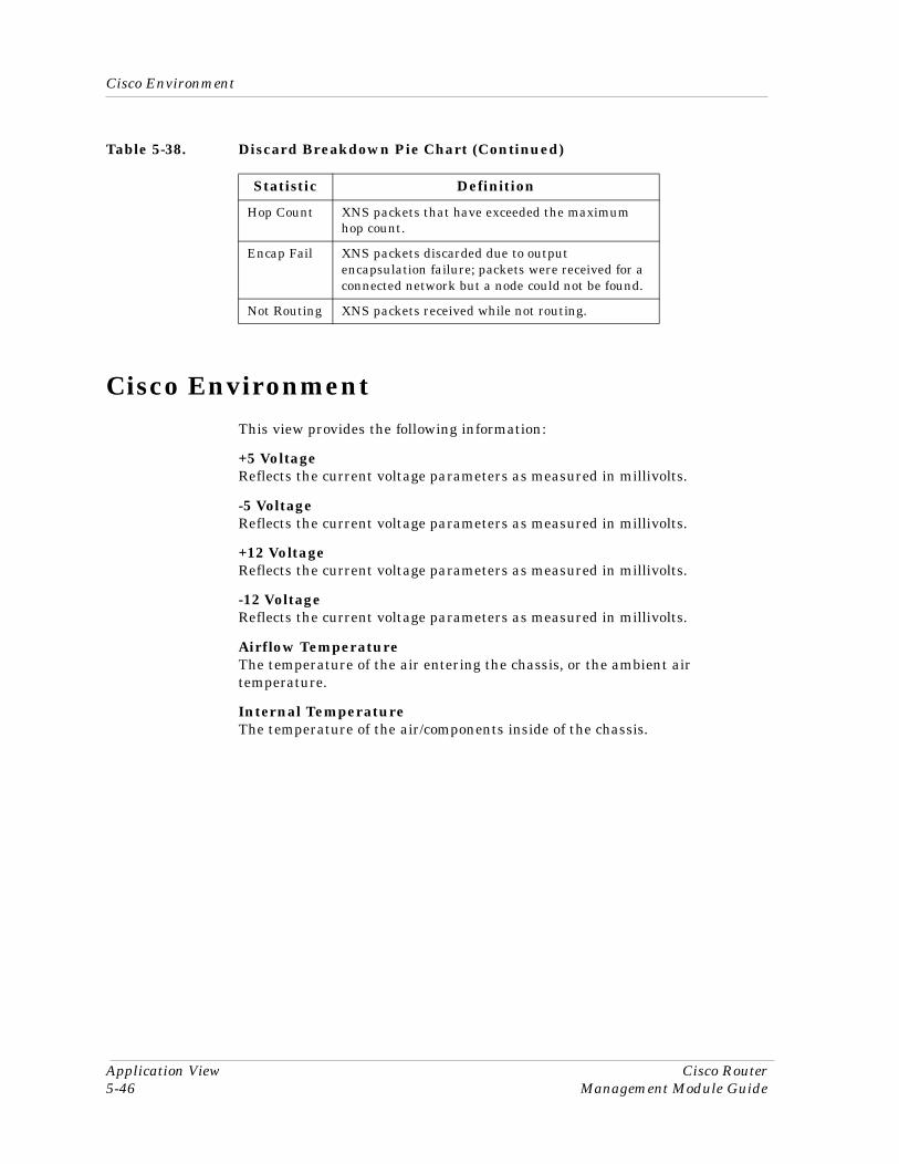
Cisco Environment
Application View Cisco Router5-46 Management Module Guide
Cisco Environment This view provides the following information:
+5 VoltageReflects the current voltage parameters as measured in millivolts.
-5 VoltageReflects the current voltage parameters as measured in millivolts.
+12 VoltageReflects the current voltage parameters as measured in millivolts.
-12 VoltageReflects the current voltage parameters as measured in millivolts.
Airflow TemperatureThe temperature of the air entering the chassis, or the ambient air temperature.
Internal TemperatureThe temperature of the air/components inside of the chassis.
Hop Count XNS packets that have exceeded the maximum hop count.
Encap Fail XNS packets discarded due to output encapsulation failure; packets were received for a connected network but a node could not be found.
Not Routing XNS packets received while not routing.
Table 5-38. Discard Breakdown Pie Chart (Continued)
Statistic Definition
9030809 E101
IndexSymbols# Connect 5-31+12 Voltage 5-46+5 Voltage 5-46
Numerics-12 Voltage 5-46-5 Voltage 5-46
AAccessing
Device View 2-1device-specific subviews 1-4Icon Subviews menu 1-4SPECTRUM views 1-3views 1-3
Accounting 5-16Address 5-37
Format 5-36Length 5-36
Administrative Status 2-4Age 5-14, 5-15Airflow Temperature 5-46Alarm
Message 4-1Alarms 4-1AppleTalk
Address Resolution Protocol 5-12Datagram Delivery Protocol 5-11Echo 5-12Name Binding Protocol 5-11Routing
Detail View 5-5Table Management Protocol 5-11Table View 5-11
Transaction Protocol 5-11Zone Information Protocol 5-12
AppleTalk Address Translation information 5-10
AppleTalk ARP Table 5-5
AppleTalk Echo View 5-5AppleTalk Port information 5-9AppleTalk Port Table AppleTalk ARP
Table 5-5AppleTalk Routing Application Views 5-6Application
Bridging 5-2CSIBridge (application type
name) 5-2Enet SDB 5-2PPP_Bridge 5-2Spanning Tree 5-2Static 5-2Transparent 5-2
Bridging - Enet SDBCt_BdgEnet_App (application type
name) 5-2Bridging - PPP_Bridge
PPP_BdgApp1474 5-2Bridging - Spanning Tree
Ct_Stp_App 5-2Bridging - Static
Static_App 5-2Bridging - Transparent
Transparnt_App 5-2DS1 5-2
CtWANAppDS1 5-2Frame Relay 5-2
rfc1315App 5-2MIB-II 5-2
ICMP 5-2IP 5-2SNMP2_Agent (application type
name) 5-2System 5-2UDP 5-2
MIB-II - ICMPICMP_App 5-2
MIB-II - IPIP2_App 5-2
MIB-II - SystemSystem2_App 5-2

Index Cisco Router2 Management Module Guide
A (continued)MIB-II - UDP
UDP2_App 5-2PPP 5-2
PPP_LCPApp1471 5-2RS-232 5-2
CtWANAppRS232 5-2RS-232sync 5-2
RS-232 - RS-232syncRFC1317sync 5-2
View 5-1WAN 5-2
CtWANApp 5-2Application type name
CSIBridge 5-2Ct_BdgEnet_App 5-2Ct_Stp_App 5-2CtWANApp 5-2CtWANAppDS1 5-2CtWANAppRS232 5-2ICMP_App 5-2IP2_App 5-2PPP_BdgApp1474 5-2PPP_LCPApp1471 5-2rfc1315App 5-2RFC1317sync 5-2SNMP2_Agent 5-2Static_App 5-2System2_App 5-2Transparnt_App 5-2UDP2_App 5-2
Application ViewDevice Application 5-2Common Applications 5-2
Area Table 5-5, 5-14ARP 5-12
Probe 5-12Replies 5-12Request 5-12
ARP Interface Index 5-10ARP Network Address 5-10ARP Physical Address 5-10ARP Table 5-10AT Protocol Stats 5-11ATP 5-11
Receives 5-11ATPORT Table 5-9Audience xiAuto System 5-32
Available 5-24
BBad 5-15, 5-16
Level 1 5-42Bandwidth 3-10B-casts Forwarded 5-22Bridging 5-2
Application Views 5-32Enet SDB 5-2PPP_Bridge 5-2Spanning Tree 5-2Static 5-2Transparent 5-2
Broadcast 5-36Broadcasts 5-22Buffer
Allocation 5-13Busies 5-29Button
Apply 2-8Close 2-8Default 2-8Keep Settings 2-8Reset 2-8
Button Names xiiButtons xiiBytes 5-17
CCapabilities 5-38Catalyst VLan Manager
Discovery Application 5-37CDP Application 5-28Change
Reason 3-9Channel
Application 5-28Card Table 5-28Interface Processor 5-28View 5-28
9030809 E10 Index3
C (continued)Chassis
App 5-26ID/Serial No. 5-27Information 5-27Slot Table 5-26Type 5-27
CheckpointAccounting
Button 5-17Table 5-17
Traffic Matrix 5-17View Information 5-17
CheckSum 5-13, 5-43, 5-44, 5-45Chip Set 5-23CIP 5-28Circuit Table View 5-34Cisco
ChannelApplication Model Type Names 5-28
Channel Application 5-28Channel View 5-28Chassis
Application Model Type Names 5-26Application Views 5-26Card View 5-26General Information View 5-26, 5-
27DSPU
Application Model Type Names 5-29, 5-30
DSPU Information View 5-29Environment
View 5-32FDDI Application Views 5-22Flash
Application Model Type Names 5-24Application Views 5-24Configuration View 5-24
IP Accounting Table 5-5, 5-16Routing 5-5
ApplicationViews 5-5
Sub Channel View 5-28, 5-29Terminal Server
Line View 5-30Session View 5-31
CiscoChanApp 5-28CiscoChasApp 5-26
CiscoDNApp 5-5CiscoDSPUApp 5-29CiscoFDDIApp 5-22CiscoFlashApp 5-24CiscoGenRtrApp 5-5CiscoIPApp 5-5CiscoNovellApp 5-5CiscoTSApp 5-30CiscoVinesApp 5-5CiscoXNSApp 5-5Color 2-4Committed Burst 5-35Common Applications 5-2Config
Register 5-28Connections 5-29Control Unit Busy Messages 5-29Conventions xiiCost 5-14CPU Utilization 5-29Create
Circuit 5-34Creation
Time 5-35CSIBridge 5-2Ct_BdgEnet_App 5-2Ct_Stp_App 5-2CtWANApp 5-2CtWANAppDS1 5-2CtWANAppRS232 5-2Current
Sess 5-31
DData
Link Connection Management Table View 5-35
DDP 5-11Bad 5-12Long 5-11Short 5-11
DECnetAddress 5-14Circuit 5-15Hello Statistics 5-16Packets 5-14Protocol 5-14, 5-15Routing
Application Views 5-14

Index Cisco Router4 Management Module Guide
D (continued)Detail View 5-42Hello View 5-5, 5-16Level 1 Statistics 5-15Level 1 View 5-5, 5-15Level 2 Statistics 5-16Level 2 View 5-5, 5-16
Delivered 5-12, 5-42, 5-43, 5-44, 5-45Description 5-27Destination 5-17Device
Errors 5-29Device Application View 5-2
Icon Mode 5-3List Mode 5-4
Device ID 5-37Device Port 5-38Device View 2-1
Description 2-1Discard 5-12Discards 5-42, 5-43, 5-44, 5-45Discovery 5-38Discovery Cache Table View 5-37DLCI 5-34DLCM Table 5-35Double-Click Access
From Interface Options Panel - Gauge Control Panel 2-5, 2-6
Double-click zones 1-3DS1 5-2DSPU 5-29
Information View 5-29DSPU Application 5-29
EEcho
Count 5-21In 5-20Out 5-20Receives 5-12
Echo View 5-11Echo View (AppleTalk) information 5-11EGP
Application 5-32Neighbor Table View 5-32Neighbor View 5-32
Encap Fail 5-13, 5-43, 5-44, 5-45, 5-46Encapsulation
Failure 5-13, 5-43, 5-44, 5-45, 5-46Type 5-21
Enquiry Interval 5-36Erase Flash Button 5-25Erasure 5-25Error
Packet 5-37Table View 5-36Threshold 5-36
Error_Ct 5-23Errors 5-12, 5-42, 5-43, 5-44, 5-45Ethernet
Address 2-4, 3-10Event
Messages 4-1Trigger 5-33
Events 4-1Excess Burst 5-35
FFCS Errors 5-9FDDI
App 5-22Application 5-22
Model Type Name 5-22, 5-34Application Views 5-41MAC Information 5-23Ring 5-23SMT Information 5-23Station 5-24
Firmware 5-25Flash
App 5-24Directory 5-25File Name 5-26Memory 5-24Size 5-24To Net
Operation View 5-25To Net Button 5-25
Flow Control 5-30Format Error 5-21Forward 5-12, 5-21, 5-42, 5-43, 5-44, 5-45Forwarded 5-21Frame
Relay 5-33, 5-34Frame Relay 5-2Frame_Ct 5-23

9030809 E10 Index5
F (continued)Frames
Received 5-35Sent 5-35
Free Memory 5-29
GGauge Control Panel 2-6
Gauge Buttons 2-8Apply 2-8Close 2-8Default 2-8Keep Settings 2-8Reset 2-8
Gauge Mode 2-6Percentages 2-6Rate 2-7Totals 2-7
Gauge Type 2-8Selected Attribute 2-8
Gauge ModePercentages 2-6Rate 2-7Totals 2-7
Group 5-38
HHardware
Chips 5-23Revision Level 5-27Ver. 5-27
Header 5-42, 5-43, 5-44, 5-45Hello
Statistics 5-16Hi Version 5-24Hop Count 5-13, 5-43, 5-44, 5-45, 5-46Hops 5-14, 5-15Host 5-14
Machine 5-25Table 5-5, 5-14
Host Table 5-5
IIANA Conventions 5-23ICMP_App 5-2
Icon Subviews menuaccessing 1-4accessing views 1-4
ICPIn 5-20Out 5-20
Idle T-out 5-31IF
StatusView Label 2-4
Illegal Echos 5-12In
ErrorMsgs 5-33
Errors 5-32, 5-45Msgs 5-32
In Packets 5-9Index 5-23, 5-28, 5-29, 5-34, 5-35, 5-36Installed 5-25Interface 5-14, 5-15
Address Translation Table 2-4Cost
Table 5-5, 5-15Options Panel 2-5Status View 2-4
Interface Discovery Status Table 5-38Interface Index 5-9Interface Options Panel 2-5
Filter 2-5Gauge Control Panel 2-6
Gauge Buttons 2-8Gauge Mode 2-6Gauge Type 2-8Selected Attribute 2-8
Interface Description 2-5Network Information 2-5
Address 2-5Mask 2-5Name 2-5
Internal Temperature 5-46Interval 5-38
Hellos 5-33Polls 5-33
Introduction 1-1

Index Cisco Router6 Management Module Guide
I (continued)IP
Accounting Table 5-17Address 2-4
Table 5-5Configuration
View 5-5Fragmentation
View 5-5Reassembly
View 5-5Routing
Table 5-5IP2_App 5-2IPC
Count 5-22Error Count 5-22
Isolated 5-24
KKinetics Internet Protocol information 5-7Kinetics Internet Protocol Table 5-5Kip Broadcast Add 5-7Kip Core 5-7Kip Hop Count 5-7Kip Net End 5-7Kip Net Start 5-7Kip Next Hop 5-7Kip Share 5-7Kip State 5-7KIP Table 5-7Kip Type 5-7
LLAN 1-2
ONLY 5-21Last
Change 3-9, 5-35Error 5-37Flash
Erase Time 5-25Net Copy Time 5-26
Net To Flash Copy Time 5-25Length Errors 5-9Line
Table 5-30View 5-30
ll be two bytes of zero. 5-8LLAP Table 5-8Local Destination 5-21LocalTalk Interface Table 5-5LocalTalk Link Access Protocol (LLAP)
information 5-8Location 5-30Logical Module
Chassis 1-4Lost_Ct 5-23Low
Version 5-24
MMAC
Address 2-4, 3-10Count 5-23In 5-20Index 5-23Out 5-20Table 5-22, 5-23
MaxSupported VCs 5-36
Menu Navigation xiiMenu Selections xiiMetric Out 5-20MIB-II 5-2
ApplicationViews 5-32
Detail View 5-5ICMP 5-2IP 5-2System 5-2UDP 5-2
Missing 5-25Mode 5-33Model
TypeDescriptions 1-2Names 5-5, 5-22, 5-24, 5-26, 5-28, 5-
29, 5-30, 5-33Modem Control 5-30Monitored Events 5-36Multicast 5-36

9030809 E10 Index7
NName 5-29Name Binding Index 5-8Name Binding Object 5-8Name Binding Protocol information 5-7Name Binding Protocol Table 5-5, 5-7Name Binding State 5-8Name Binding Type 5-8Name Binding Zone 5-8NBP 5-11
Receives 5-11Sent 5-11
nd Net.Node 5-10Neighbor
Address 5-32State 5-32Table 5-32
NetTo Flash
Button 5-25Operation View 5-25
NetworkAddress 3-9Information Panel 2-5Name 3-9Servers 1-2Traffic
Flow 5-16, 5-17Network Information
Address 2-5Mask 2-5Name 2-5
Next Hop 5-14, 5-15No
Access 5-13, 5-43Buffer 5-13Charge 5-21Routes 5-13, 5-43, 5-44, 5-45
No Data Errors 5-9No Handler 5-9Non-volatile RAM
Size (bytes) 5-28Used (bytes) 5-28
NotForward 5-21LAN 5-21Routing 5-46
Notice iNovell
Packets 5-43Routing
Application Views 5-17Detail View 5-43
SAPStatistics 5-18View 5-5, 5-17, 5-18
Service Advertisement Protocol View 5-17, 5-18
Numberof Chassis Slots 5-27
OOctets
Received 5-35Sent 5-35
Operation Status 3-9Operational Status 2-4Other 5-15, 5-16Out
ErrorMsgs 5-33
Errors 5-33, 5-45Msgs 5-33
Out Packets 5-9OVER 4800 BPS 5-21
PPacket
Size 3-10Packets 5-17PC Local Area Networks 1-2Physical
Address 3-10Platform 5-38Polling
Interval 5-36Port 5-38Port Description 5-10Port If Index 5-10Port Index 5-9Port Net Address 5-10Port Net Config 5-10Port Status 5-10Port Type 5-10Port Zone 5-10Port Zone Config 5-10

Index Cisco Router8 Management Module Guide
P (continued)PPP 5-2PPP_BdgApp1474 5-2PPP_LCPApp1471 5-2Preface xiPrint Button 5-25Priority 5-14, 5-15Probable Cause Messages 4-1Proxy Count 5-22
RRAM Information 5-28Random CTS Errors 5-9Rcvd
BECNs 5-34FECNs 5-34
Received 5-15, 5-16, 5-21Re-Initialization 5-23Related Documentation xiiiRelated SPECTRUM Documentation xiiRemote Network Servers 1-2Replies
Rec 5-22Sent 5-22
Reprogramming 5-25Request
Out 5-22Rec 5-22
Restricted Rights Notice iirfc1315App 5-2, 5-33, 5-34
Circuit Table 5-34Data Link Connection Management
Table 5-35DLCM Table 5-35Error Table 5-36
RFC1317sync 5-2Roadmap 1-5
SPECTRUMroadmap of views 1-5
ROMInformation 5-27Monitor Version 5-28Software Version 5-28
RouterModels 1-1
RoutingApplication
Model Type Names 5-5
Views 5-5Packets 5-15Statistics 5-15
Routing Protocol Comparison View 5-6RS/232 5-2RS-232
RS-232sync 5-2RTMP 5-11
Receives 5-11Sent 5-11
RTMP Table 5-5Rtr 1-2Rtr_CiscoIGS 1-2Rtr_CiscoMGS 1-2Rtr_CiscoMIM 1-2Rtr_CiscoMIM3T 1-2
SSAP
Chart 5-18Replies Sent 5-18Requests
Rec 5-18Sent 5-18
Responses Rec 5-18SAP/IPX 5-18Security
Jumper 5-25Sent 5-15, 5-16Serial Number 5-27Server File Name 5-25Sess T-out 5-31Session
Table 5-31View 5-31
Slot 5-26SMT
Count 5-23Index 5-23Table 5-22, 5-23
SNMP2_Agent 5-2Software
Ver. 5-27Source 5-17SPECTRUM
accessing 1-3roadmap of views 1-5views
roadmap 1-5

9030809 E10 Index9
S (continued)SPECTRUM Documentation xiiSpeed
In 5-30Out 5-30
Start Net.Node 5-10State 5-24, 5-34, 5-36
Downs 5-33Ups 5-33
Static_App 5-2Station ID 5-24Status 5-30Sub Channel
Table 5-29View 5-29
SystemCPU RAM (bytes) 5-28Restarts 5-29
System2_App 5-2
TTarget
Network Host 5-26Token Rotation Time 5-23
TCP/IP Based Networks xiiiTerm Type 5-30Terminal Server
Application Views 5-30Line Table 5-30Line View 5-30Session View 5-31
Terminal Srvr 5-30Text Display 2-4TFTP Server Network Address 5-25, 5-26Throughput 5-34Thru 5-24Time Detected 5-37T-Max 5-23T-Min 5-23T-Neg 5-23Total Collision 5-9Total Defer 5-9Total In Errors 5-9Total Memory 5-29Trademarks iTransmission
Time 5-23Transmitted 5-12, 5-21, 5-42, 5-43, 5-44, 5-
45Transparnt_App 5-2T-Req 5-23TS Session Table 5-31TTRT 5-23TVX Counter 5-23TvxValue 5-23Type 5-26, 5-30, 5-37
UUDP2_App 5-2Unicasts 5-22Unknown 5-13, 5-44, 5-45Using double-click zones 1-3
VVersion ID 5-24View
Device Application 5-2Vines
BroadcastDetail View 5-5, 5-21Packets 5-21Statistics 5-21
EchoPackets 5-20Statistics 5-20
ICP 5-20Metric Notification 5-20Packets 5-20Statistics 5-20
Interprocess Communications Protocol 5-20
Packets 5-44Routing
Application Views 5-18Detail View 5-44Echo View 5-5, 5-20ICP View 5-5, 5-20
Rx View 5-5, 5-21Tx View 5-5, 5-21
Virus Disclaimer iVPP Dip 5-25

Index Cisco Router10 Management Module Guide
WWAN 5-2Wrap
A 5-24AB 5-24B 5-24S 5-24
XXNS
EchoReply 5-22Statistics 5-22
Packets 5-45Routing
Application Views 5-22Detail View 5-45Echo View 5-5
ZZIP 5-12
Received 5-12Sent 5-12
ZIP Table 5-8Zone Information Protocol (ZIP)
information 5-8Zone Information Table 5-5Zone Net End 5-8Zone Net Start 5-8Zone State 5-8