cisco router and security device manager (sdm) version … · connectivity testing and...
TRANSCRIPT

Cisco Router and Security Device Manager (SDM) Version 2.2 User’s Guide
Corporate HeadquartersCisco Systems, Inc.170 West Tasman DriveSan Jose, CA 95134-1706 USAhttp://www.cisco.comTel: 408 526-4000
800 553-NETS (6387)Fax: 408 526-4100
Customer Order Number: Text Part Number: OL-4015-08

THE SPECIFICATIONS AND INFORMATION REGARDING THE PRODUCTS IN THIS MANUAL ARE SUBJECT TO CHANGE WITHOUT NOTICE. ALL STATEMENTS, INFORMATION, AND RECOMMENDATIONS IN THIS MANUAL ARE BELIEVED TO BE ACCURATE BUT ARE PRESENTED WITHOUT WARRANTY OF ANY KIND, EXPRESS OR IMPLIED. USERS MUST TAKE FULL RESPONSIBILITY FOR THEIR APPLICATION OF ANY PRODUCTS.
THE SOFTWARE LICENSE AND LIMITED WARRANTY FOR THE ACCOMPANYING PRODUCT ARE SET FORTH IN THE INFORMATION PACKET THAT SHIPPED WITH THE PRODUCT AND ARE INCORPORATED HEREIN BY THIS REFERENCE. IF YOU ARE UNABLE TO LOCATE THE SOFTWARE LICENSE OR LIMITED WARRANTY, CONTACT YOUR CISCO REPRESENTATIVE FOR A COPY.
The Cisco implementation of TCP header compression is an adaptation of a program developed by the University of California, Berkeley (UCB) as part of UCB’s public domain version of the UNIX operating system. All rights reserved. Copyright © 1981, Regents of the University of California.
NOTWITHSTANDING ANY OTHER WARRANTY HEREIN, ALL DOCUMENT FILES AND SOFTWARE OF THESE SUPPLIERS ARE PROVIDED “AS IS” WITH ALL FAULTS. CISCO AND THE ABOVE-NAMED SUPPLIERS DISCLAIM ALL WARRANTIES, EXPRESSED OR IMPLIED, INCLUDING, WITHOUT LIMITATION, THOSE OF MERCHANTABILITY, FITNESS FOR A PARTICULAR PURPOSE AND NONINFRINGEMENT OR ARISING FROM A COURSE OF DEALING, USAGE, OR TRADE PRACTICE.
IN NO EVENT SHALL CISCO OR ITS SUPPLIERS BE LIABLE FOR ANY INDIRECT, SPECIAL, CONSEQUENTIAL, OR INCIDENTAL DAMAGES, INCLUDING, WITHOUT LIMITATION, LOST PROFITS OR LOSS OR DAMAGE TO DATA ARISING OUT OF THE USE OR INABILITY TO USE THIS MANUAL, EVEN IF CISCO OR ITS SUPPLIERS HAVE BEEN ADVISED OF THE POSSIBILITY OF SUCH DAMAGES.
Cisco Router and Security Device Manager (SDM) Version 2.2 User’s GuideCopyright © 2005, Cisco Systems, Inc.All rights reserved.
CCSP, the Cisco Square Bridge logo, Cisco Unity, Follow Me Browsing, FormShare, and StackWise are trademarks of Cisco Systems, Inc.; Changing the Way We Work, Live, Play, and Learn, and iQuick Study are service marks of Cisco Systems, Inc.; and Aironet, ASIST, BPX, Catalyst, CCDA, CCDP, CCIE, CCIP, CCNA, CCNP, Cisco, the Cisco Certified Internetwork Expert logo, Cisco IOS, Cisco Press, Cisco Systems, Cisco Systems Capital, the Cisco Systems logo, Empowering the Internet Generation, Enterprise/Solver, EtherChannel, EtherFast, EtherSwitch, Fast Step, GigaDrive, GigaStack, HomeLink, Internet Quotient, IOS, IP/TV, iQ Expertise, the iQ logo, iQ Net Readiness Scorecard, LightStream, Linksys, MeetingPlace, MGX, the Networkers logo, Networking Academy, Network Registrar, Packet, PIX, Post-Routing, Pre-Routing, ProConnect, RateMUX, Registrar, ScriptShare, SlideCast, SMARTnet, StrataView Plus, SwitchProbe, TeleRouter, The Fastest Way to Increase Your Internet Quotient, TransPath, and VCO are registered trademarks of Cisco Systems, Inc. and/or its affiliates in the United States and certain other countries.
All other trademarks mentioned in this document or Website are the property of their respective owners. The use of the word partner does not imply a partnership relationship between Cisco and any other company. (0406R)
Cisco Router anOL-4015-06
C O N T E N T S
Home Page 1
LAN Wizard 1
Ethernet Configuration 2
LAN Wizard: Select an Interface 3
LAN Wizard: IP Address and Subnet Mask 3
LAN Wizard: Enable DHCP Server 4
LAN Wizard: DHCP Address Pool 4
DHCP Options 5
LAN Wizard: VLAN Mode 6
LAN Wizard: Switch Port 6
IRB Bridge 7
BVI Configuration 7
DHCP Pool for BVI 8
IRB for Ethernet 9
Layer 3 Ethernet Configuration 9
802.1Q Configuration 9
Trunking or Routing Configuration 9
Configure Switch Device Module 10
Summary 10
How Do I... 10
How Do I Configure a Static Route? 10
How Do I View Activity on My LAN Interface? 11
How Do I Enable or Disable an Interface? 12
iiid Security Device Manager (SDM) Version 2.1 User’s Guide

Contents
How Do I View the IOS Commands I Am Sending to the Router? 12
How Do I Launch the Wireless Application from SDM? 13
Create Connection Wizards 1
Create Connection 1
WAN Wizard Interface Welcome Window 2
ISDN Wizard Welcome Window 3
Analog Modem Welcome Window 3
Aux Backup Welcome Window 3
Select Interface 4
Encapsulation: PPPoE 4
IP Address: ATM or Ethernet with PPPoE/PPPoA 4
IP Address: ATM with RFC 1483 Routing 5
IP Address: Ethernet without PPPoE 6
IP Address: Serial with Point-to-Point Protocol 6
IP Address: Serial with HDLC or Frame Relay 7
IP Address: ISDN BRI or Analog Modem 8
Authentication 9
Switch Type and SPIDs 9
Dial String 11
Backup Configuration 11
Backup Configuration: Primary Interface & Next Hop IP Addresses 12
Backup Configuration: Hostname or IP Address to be Tracked 12
Advanced Options 13
Encapsulation 13
PVC 15
Configure LMI and DLCI 16
Configure Clock Settings 17
ivCisco Router and Security Device Manager (SDM) Version 2.1 User’s Guide
OL-4015-06

Contents
Delete Connection 19
Summary 21
Connectivity testing and troubleshooting 22
How Do I... 26
How Do I View the IOS Commands I Am Sending to the Router? 26
How Do I Configure an Unsupported WAN Interface? 26
How Do I Enable or Disable an Interface? 26
How Do I View Activity on My WAN Interface? 27
How Do I Configure NAT on a WAN Interface? 27
How Do I Configure NAT on an Unsupported Interface? 28
How Do I Configure a Dynamic Routing Protocol? 28
How Do I Configure Dial-on-Demand Routing for my ISDN or Asynchronous Interface? 29
How Do I Edit a Radio Interface Configuration? 30
Edit Interface/Connection 1
Connection: Ethernet for IRB 6
Connection: Ethernet for Routing 7
Existing Dynamic DNS Methods 8
Add Dynamic DNS Method 8
Wireless 10
Association 10
NAT 12
Edit Switch Port 12
General 13
QoS 15
Select Ethernet Configuration Type 16
Connection: VLAN 16
Connection: Subinterfaces 17
vCisco Router and Security Device Manager (SDM) Version 2.1 User’s Guide
OL-4015-06

Contents
Add or Edit BVI Interface 18
Add Loopback Interface/Connection—Loopback 18
Connection: Ethernet LAN 19
Connection: Ethernet WAN 20
Ethernet Properties 21
Connection: Ethernet with No Encapsulation 22
Connection: ADSL 23
Connection: ADSL over ISDN 26
Connection: G.SHDSL 28
Configure DSL Controller 32
Connection: G.SHDSL with DSL Controller 34
Connection: Serial Interface, Frame Relay Encapsulation 36
Connection: Serial Interface, PPP Encapsulation 39
Connection: Serial Interface, HDLC Encapsulation 41
Add or Edit GRE Tunnel' 42
Connection: ISDN BRI 44
Connection: Analog Modem 47
Connection: (AUX Backup) 49
Authentication 51
SPID Details 52
Dialer Options 53
Backup Configuration 55
Create Firewall 1
Basic Firewall Configuration Wizard 4
Basic Firewall Interface Configuration 4
Firewall Remote Management Access 4
Advanced Firewall Configuration Wizard 5
viCisco Router and Security Device Manager (SDM) Version 2.1 User’s Guide
OL-4015-06
Contents
Advanced Firewall Interface Configuration 5
Advanced Firewall DMZ Service Configuration 6
DMZ Service Configuration 7
Advanced Firewall Inspection Rule Configuration 7
Application Security Configuration 9
Domain Name Server Configuration 10
Summary 10
How Do I... 11
How Do I View Activity on My Firewall? 12
How Do I Configure a Firewall on an Unsupported Interface? 13
How Do I Configure a Firewall After I Have Configured a VPN? 14
How Do I Permit Specific Traffic Through a DMZ Interface? 15
How Do I Modify an Existing Firewall to Permit Traffic from a New Network or Host? 16
How Do I Configure NAT on an Unsupported Interface? 16
How Do I Configure NAT Passthrough for a Firewall? 17
How Do I Permit Traffic Through a Firewall to My Easy VPN Concentrator? 17
How Do I Associate a Rule with an Interface? 19
How Do I Disassociate an Access Rule from an Interface 19
How Do I Delete a Rule That Is Associated with an Interface? 20
How Do I Create an Access Rule for a Java List? 20
How Do I Permit Specific Traffic onto My Network if I Don’t Have a DMZ Network? 21
Firewall Policy 1
Edit Firewall Policy/ACL 1
Add App-Name Application Entry 11
Add rpc Application Entry 11
Add Fragment application entry 12
Add or Edit http Application Entry 13
Java Applet Blocking 14
viiCisco Router and Security Device Manager (SDM) Version 2.1 User’s Guide
OL-4015-06
Contents
SDM Warning: Inspection Rule 15
SDM Warning: Firewall 16
Application Security 17
Application Security Windows 17
No Application Security Policy 19
E-mail 20
HTTP 21
Header Options 23
Content Options 23
Instant Messaging 25
Point-to-Point Applications 25
Applications/Protocols 26
Global Timeouts and Thresholds 27
Associate Policy with an Interface 29
Edit Inspection Rule 30
Permit, Block, and Alarm Controls 31
Site-to-Site VPN 33
Create Site to Site VPN 33
Site-to-Site VPN Wizard 36
View Defaults 37
VPN Connection Information 38
IKE Proposals 40
Transform Set 43
Traffic to Protect 45
Summary of the Configuration 46
Spoke Configuration 47
Secure GRE Tunnel (GRE-over-IPSec) 48
GRE Tunnel Information 48
viiiCisco Router and Security Device Manager (SDM) Version 2.1 User’s Guide
OL-4015-06

Contents
VPN Authentication Information 49
Backup GRE Tunnel Information 51
Routing Information 52
Static Routing Information 53
Select Routing Protocol 54
Summary of Configuration 55
Edit Site-to-Site VPN 55
Add new connection 58
Add Additional Crypto Maps 59
Crypto Map Wizard: Welcome 60
Crypto Map Wizard: General 60
Crypto Map Wizard: Peers 62
Crypto Map Wizard: Transform Set 62
Crypto Map Wizard: Traffic to Protect 63
Crypto Map Wizard: Summary of the configuration 64
Delete Connection 65
Ping 65
Generate Mirror... 66
SDM Warning: NAT Rules with ACL 67
How Do I... 67
How Do I Create a VPN to More Than One Site? 68
After Configuring a VPN, How Do I Configure the VPN on the Peer Router? 70
How Do I Edit an Existing VPN Tunnel? 71
How Do I Confirm That My VPN Is Working? 72
How Do I Configure a Backup Peer for My VPN? 73
How Do I Accommodate Multiple Devices with Different Levels of VPN Support? 73
How Do I Configure a VPN on an Unsupported Interface? 74
How Do I Configure a VPN After I Have Configured a Firewall? 75
How Do I Configure NAT Passthrough for a VPN? 75
ixCisco Router and Security Device Manager (SDM) Version 2.1 User’s Guide
OL-4015-06

Contents
Easy VPN Remote 77
Create Easy VPN Remote 77
Configure an Easy VPN Remote Client 77
Connection Settings 78
Authentication 79
Interfaces 80
Summary of Configuration 82
Edit Easy VPN Remote 83
Add or Edit Easy VPN Remote 89
Add or Edit Easy VPN Remote: Easy VPN Settings 91
Add or Edit Easy VPN Remote: Authentication Information 94
Enter SSH Credentials 95
XAuth Login Window 96
Add or Edit Easy VPN Remote: General Settings 96
Network Extension Options 98
Add or Edit Easy VPN Remote: Authentication Information 98
Add or Edit Easy VPN Remote: Interfaces and Connections 100
How Do I... 101
How Do I Edit an Existing Easy VPN Connection? 102
How Do I Configure a Backup for an Easy VPN Connection? 102
Easy VPN Server 105
Create an Easy VPN Server 105
Welcome to the Easy VPN Server Wizard 106
Interface and Authentication 106
Group Authorization: Group Policy Lookup 107
User Authentication (XAuth) 108
User Accounts for XAuth 109
Add RADIUS Server 109
Group Authorization: User Group Policies 110
xCisco Router and Security Device Manager (SDM) Version 2.1 User’s Guide
OL-4015-06

Contents
General Group Information 111
DNS and WINS Configuration 112
Split Tunneling 113
Client Settings 115
Choose Browser Proxy Settings 117
Add or Edit Browser Proxy Settings 117
User Authentication (XAuth) 119
Client Update 120
Add or Edit Client Update Entry 121
Summary 121
Browser Proxy Settings 122
Add or Edit Easy VPN Server 123
Add or Edit Easy VPN Server Connection 125
Restrict Access 126
Group Policies Configuration 126
Local Pools 129
Add or Edit IP Local Pool 130
Add IP Address Range 130
DMVPN 1
Dynamic Multipoint VPN 1
Dynamic Multipoint VPN (DMVPN) Hub Wizard 2
Type of Hub 3
Configure Pre-Shared Key 3
Hub GRE Tunnel Interface Configuration 4
Advanced Configuration for the Tunnel Interface 5
Primary Hub 6
Select Routing Protocol 7
Routing Information 7
Dynamic Multipoint VPN (DMVPN) Spoke Wizard 9
xiCisco Router and Security Device Manager (SDM) Version 2.1 User’s Guide
OL-4015-06

Contents
DMVPN Network Topology 9
Specify Hub Information 10
Spoke GRE Tunnel Interface Configuration 10
SDM Warning: DMVPN Dependency 11
Edit Dynamic Multipoint VPN (DMVPN) 12
General Panel 14
NHRP Panel 15
NHRP Map Configuration 16
Routing Panel 17
How Do I Configure a DMVPN Manually? 19
VPN Global Settings 21
VPN Global Settings 21
VPN Global Settings: IKE 23
VPN Global Settings: IPSec 24
VPN Key Encryption Settings 25
IP Security 27
IPSec Policies 27
Add or Edit IPSec Policy 29
Add or Edit Crypto Map: General Panel 31
Add or Edit Crypto Map: Peer Information Panel 32
Add or Edit Crypto Map: Transform Sets Panel 32
Add or Edit Crypto Map: IPSec Rules Panel 34
Dynamic Crypto Map Sets 35
Add or Edit Dynamic Crypto Map Set 35
Associate Crypto Map with this IPSec Policy 36
IPSec Profiles 36
Add or Edit IPSec Profile and Add Dynamic Crypto Map 37
Transform Set 37
xiiCisco Router and Security Device Manager (SDM) Version 2.1 User’s Guide
OL-4015-06

Contents
Add or Edit Transform Set 40
IPSec Rules 43
Internet Key Exchange 45
Internet Key Exchange (IKE) 45
IKE Policies 46
Add or Edit IKE Policy 48
IKE Pre-shared Keys 50
Add or Edit Pre Shared Key 51
VPN Troubleshooting 53
VPN Troubleshooting 53
VPN Troubleshooting: Specify Easy VPN Client 55
VPN Troubleshooting: Generate Traffic 56
VPN Troubleshooting: Generate GRE Traffic 57
SDM Warning: SDM will enable router debugs... 58
Security Audit 1
Welcome Page 4
Interface Selection Page 4
Report Card Page 5
Fix It Page 5
Disable Finger Service 6
Disable PAD Service 7
Disable TCP Small Servers Service 7
Disable UDP Small Servers Service 8
Disable IP BOOTP Server Service 8
Disable IP Identification Service 9
Disable CDP 9
Disable IP Source Route 10
xiiiCisco Router and Security Device Manager (SDM) Version 2.1 User’s Guide
OL-4015-06

Contents
Enable Password Encryption Service 10
Enable TCP Keepalives for Inbound Telnet Sessions 11
Enable TCP Keepalives for Outbound Telnet Sessions 11
Enable Sequence Numbers and Time Stamps on Debugs 11
Enable IP CEF 12
Disable IP Gratuitous ARPs 12
Set Minimum Password Length to Less Than 6 Characters 12
Set Authentication Failure Rate to Less Than 3 Retries 13
Set TCP Synwait Time 13
Set Banner 14
Enable Logging 14
Set Enable Secret Password 15
Disable SNMP 15
Set Scheduler Interval 16
Set Scheduler Allocate 16
Set Users 17
Enable Telnet Settings 17
Enable NetFlow Switching 17
Disable IP Redirects 18
Disable IP Proxy ARP 18
Disable IP Directed Broadcast 19
Disable MOP Service 20
Disable IP Unreachables 20
Disable IP Mask Reply 20
Disable IP Unreachables on NULL Interface 21
Enable Unicast RPF on Outside Interfaces 22
Enable Firewall on All of the Outside Interfaces 22
Set Access Class on HTTP Server Service 23
Set Access Class on VTY Lines 23
Enable SSH for Access to the Router 24
xivCisco Router and Security Device Manager (SDM) Version 2.1 User’s Guide
OL-4015-06

Contents
Enable AAA 24
Configuration Summary Screen 25
SDM and Cisco IOS AutoSecure 25
Security Configurations SDM Can Undo 27
Undoing Security Audit Fixes 28
Add or Edit Telnet/SSH Account Screen 28
Configure User Accounts for Telnet/SSH Page 29
Enable Secret and Banner Page 30
Logging Page 31
Routing 1
Add or Edit IP Static Route 3
Add or Edit an RIP Route 5
Add or Edit an OSPF Route 5
Add or Edit EIGRP Route 7
Network Address Translation 1
Network Address Translation Wizards 1
Basic NAT Wizard: Welcome 2
Basic NAT Wizard: Connection 2
Summary 3
Advanced NAT Wizard: Welcome 3
Advanced NAT Wizard: Connection 4
Add IP Address 4
Advanced NAT Wizard: Networks 4
Add Network 5
Advanced NAT Wizard: Server Public IP Addresses 5
Add or Edit Address Translation Rule 6
Advanced NAT Wizard: VPN Conflict 8
xvCisco Router and Security Device Manager (SDM) Version 2.1 User’s Guide
OL-4015-06

Contents
Details 8
Network Address Translation Rules 8
Designate NAT Interfaces 12
Translation Timeout Settings 12
Edit Route Map 14
Edit Route Map Entry 15
Address Pools 15
Add or Edit Address Pool 16
Add or Edit Static Address Translation Rule: Inside to Outside 17
Add or Edit Static Address Translation Rule: Outside to Inside 20
Add or Edit Dynamic Address Translation Rule: Inside to Outside 23
Add or Edit Dynamic Address Translation Rule: Outside to Inside 26
How Do I . . . 28
How Do I Configure NAT With One LAN and Multiple WANs? 28
Intrusion Prevention System 31
IPS Rules 32
Create IPS Rule 32
Welcome to the IPS Rule Configuration Wizard 33
Select Interfaces 33
SDF Location 33
IPS Rule Wizard Summary 34
IPS Rules Configuration 34
Enable or Edit IPS on an Interface 37
Import Signatures 38
File Selection 39
Welcome to the IPS Signature Import Wizard 40
Signature Definition File (SDF) and Signature Selection 40
Signature Filter 40
Signature Edit 41
xviCisco Router and Security Device Manager (SDM) Version 2.1 User’s Guide
OL-4015-06

Contents
Signature Import Wizard Summary 41
Signatures 42
Assign Actions 46
Import Signatures 46
Add, Edit, or Clone Signature 48
Add or Edit a Signature Location 49
Cisco Intrusion Prevention Alert Center 50
IPS-Supplied Signature Definition Files 50
Global Settings 51
Edit Global Settings 53
SDEE Messages 54
SDEE Message Text 55
Network Module Management 1
IDS Network Module Management 1
IDS Sensor Interface IP Address 3
IP Address Determination 4
IDS NM Configuration Checklist 5
IDS NM Interface Monitoring Configuration 7
Network Module Login 7
Feature Unavailable 7
Switch Module Interface Selection 8
Quality of Service 9
Create QoS Policy 9
QoS Wizard 10
Interface Selection 10
QoS Policy Generation 10
View QoS Class Details 12
Summary of the configuration 13
xviiCisco Router and Security Device Manager (SDM) Version 2.1 User’s Guide
OL-4015-06

Contents
Edit QoS Policy 13
Edit QoS Class 15
Add a Protocol 17
Interface Association 18
QoS Status 18
Network Admission Control 21
Create NAC Tab 21
Other Tasks in a NAC Implementation 22
Welcome 23
RADIUS Server 23
Select the Interface(s) 25
NAC Exception List 25
Configure Exception List Entry Dialog 26
Policy List 27
Add Exception Policy 27
Agentless Host Policy 28
NAC Router Management Access 29
Open Interface ACL 29
Details Window 30
Summary of the configuration 30
Edit NAC Tab 31
EAPoUDP Components 31
Exception List Window 32
Exception Policies Window 32
EAPoUDP Timeouts 33
Configure a NAC Policy 34
How Do I... 35
How Do I Configure a NAC Policy Server? 35
How Do Install and Configure a Posture Agent on a Host? 35
xviiiCisco Router and Security Device Manager (SDM) Version 2.1 User’s Guide
OL-4015-06

Contents
Router Properties 1
Device Properties 1
Date and Time: Clock Properties 2
Date and Time Properties 3
NTP 4
Add or Edit NTP Server Details 5
SNTP 7
Add an NTP Server 7
Syslog 8
SNMP 8
Router Access 10
User Accounts: Configure User Accounts for Router Access 10
Add or Edit a Username 11
View Password 13
VTYs 13
Edit VTY Lines 14
Configure Management Access Policies 15
Add or Edit a Management Policy 17
Management Access Error Messages 18
SDM Warning: ANY Not Allowed 18
SDM Warning: Unsupported Access Control Entry 19
SDM Warning: SDM Not Allowed 19
SDM Warning: Current Host Not Allowed 19
SSH 20
DHCP Configuration 21
DHCP Pools 21
Add or Edit DHCP Pool 22
DHCP Bindings 23
Add or Edit DHCP Binding 24
xixCisco Router and Security Device Manager (SDM) Version 2.1 User’s Guide
OL-4015-06

Contents
DNS Properties 26
Dynamic DNS Methods 26
Add or Edit Dynamic DNS Method 27
ACL Editor 1
Useful Procedures for Access Rules and Firewalls 2
Rules Windows 3
Add or Edit a Rule 7
Associate with an Interface 9
Add a Standard Rule Entry 11
Add an Extended Rule Entry 13
Select a Rule 16
Port-to-Application Mapping 19
Port-to-Application Mappings 19
Add or Edit Port Map Entry 21
Authentication, Authorization, and Accounting 23
AAA Main Window 23
AAA Servers and Groups 24
AAA Servers Window 25
Add or Edit a TACACS+ Server 26
Add or Edit a RADIUS Server 27
Edit Global Settings 27
AAA Server Groups Window 28
Authentication and Authorization Policies 29
Authentication and Authorization Windows 29
Authentication NAC 30
Add or Edit a Method List for Authentication or Authorization 31
xxCisco Router and Security Device Manager (SDM) Version 2.1 User’s Guide
OL-4015-06

Contents
Router Provisioning 33
Router Provisioning from USB 33
Public Key Infrastructure 35
Certificate Wizards 35
Welcome to the SCEP Wizard 37
Certificate Authority (CA) Information 37
Advanced Options 39
Certificate Subject Name Attributes 39
Other Subject Attributes 40
RSA Keys 41
Summary 42
Enrollment Status 43
Cut and Paste Wizard Welcome 43
Enrollment Task 43
Enrollment Request 44
Continue with Unfinished Enrollment 44
Import CA certificate 45
Import Router Certificate(s) 46
Digital Certificates 46
Trustpoint Information 48
Certificate Details 48
Revocation Check 49
Revocation Check, CRL Only 49
RSA Keys Window 50
Generate RSA Key Pair 51
USB Tokens 52
Add or Edit USB Token 53
SDP Troubleshooting Tips 55
xxiCisco Router and Security Device Manager (SDM) Version 2.1 User’s Guide
OL-4015-06
Contents
Open Firewall 56
Open Firewall Details 57
Resetting to Factory Defaults 1
This Feature Not Supported 4
More About.... 1
IP Addresses and Subnet Masks 1
Host and Network Fields 3
Available Interface Configurations 4
DHCP Address Pools 5
Meanings of the Permit and Deny Keywords 6
Services and Ports 6
More About NAT 13
Static Address Translation Scenarios 13
Dynamic Address Translation Scenarios 16
Reasons that SDM Cannot Edit a NAT Rule 17
More About VPN 18
Cisco.com Resources 18
More about VPN Connections and IPSec Policies 19
More About IKE 21
More About IKE Policies 22
Allowable Transform Combinations 23
Reasons Why a Serial Interface or Subinterface Configuration May Be Read-Only 24
Reasons Why an ATM Interface or Subinterface Configuration May Be Read-Only 25
Reasons Why an Ethernet Interface Configuration May Be Read-Only 26
Reasons Why an ISDN BRI Interface Configuration May Be Read-Only 27
Reasons Why an Analog Modem Interface Configuration May Be Read-Only 28
xxiiCisco Router and Security Device Manager (SDM) Version 2.1 User’s Guide
OL-4015-06

Contents
Firewall Policy Use Case Scenario 29
DMVPN Configuration Recommendations 32
SDM White Papers 34
Getting Started 1
What’s New in this Release? 2
Cisco IOS Versions Supported 2
Viewing Router Information 1
Overview 2
Interface Status 6
VPN Status 8
Firewall Status 13
Application Security Log 14
NAC Status 15
Logging 17
File Menu Commands 1
Save Running Config to PC 1
Deliver Configuration to Router 1
Write to Startup Config 2
Reset to Factory Defaults 2
File Management 2
Rename 4
New Folder 5
Save SDF to PC 5
Exit 5
Unable to perform ‘squeeze flash’ 5
xxiiiCisco Router and Security Device Manager (SDM) Version 2.1 User’s Guide
OL-4015-06

Contents
Edit Menu Commands 9
Preferences 9
View Menu Commands 1
Home 1
Configure 1
Monitor 1
Running Config 2
Show Commands 2
SDM Default Rules 2
Refresh 3
Tools Menu Commands 1
Ping 1
Telnet 1
Security Audit 1
USB Token PIN Settings 2
Update SDM 3
Help Menu Commands 1
Help Topics 1
SDM on CCO 1
About this router... 1
About SDM 1
xxivCisco Router and Security Device Manager (SDM) Version 2.1 User’s Guide
OL-4015-06

Cisco Router and Security DeOL-4015-08
C H A P T E R 1
Home PageThe home page supplies basic information about the router’s hardware, software, and configuration. This page contains the following sections:
Host Name
The configured name of the router.
About Your Router
Shows basic information about your router hardware and software, and contains the following fields:
Hardware Software
Model Type Shows the router model number.
IOS Version The version of Cisco IOS software that is currently running on the router.
Available/Total Memory Available RAM/Total RAM
SDM Version The version of Cisco Cisco Router and Security Device Manager (SDM) software that is currently running on the router.
1-1vice Manager Version 2.2 User’s Guide

Chapter 1 Home Page
More...
The More... link displays a popup window providing additional hardware and software details.
• Hardware Details—In addition to the information presented in the About Your Router section, this tab displays information about:
– Where the router boots from–Flash or Configuration File.
– Whether the router has accelerators, such as VPN accelerators.
– A diagram of the hardware configuration, including flash memory and installed devices such as USB flash and USB tokens.
• Software Details—In addition to the information presented in the About Your Router section, this tab displays information about:
– The feature sets included in the IOS image.
– The version of SDM running.
Configuration Overview
This section of the home page summarizes the configuration settings that have been made.
Note If you do not see feature information described in this help topic on the home page, the Cisco IOS image does not support the feature. For example, if the router is running a Cisco IOS image that does not support security features, the Firewall Policy, VPN, and Intrusion Prevention sections do not appear on the home page.
View Running Config
Click this button to display the router’s running configuration.
Total Flash Capacity Flash plus Webflash (if applicable)
Feature Availability The features available in the Cisco IOS image the router is using are designated by a check. The features SDM checks for are: IP, Firewall, VPN, IPS, and NAC.
Hardware Software
1-2Cisco Router and Security Device Manager Version 2.2 User’s Guide
OL-4015-08

Chapter 1 Home Page
Interfaces and Connections
Up (n): The number of LAN and WAN connections that are up.
Down (n): The number of LAN and WAN connections that are down.
Double-arrow head: Click to display/hide details.
Total Supported LAN The total number of LAN interfaces that are present in the router.
Total Supported WAN The number of SDM-supported WAN interfaces that are present on the router.
Configured LAN Interface
The number of supported LAN interfaces currently configured on the router.
Total WAN Connections The total number of SDM-supported WAN connections that are present on the router.
DHCP Server Configured/Not Configured
DHCP Pool (Detail view) If one pool is configured, starting and ending address of DHCP pool.
If multiple pools are configured, list of configured pool names.
Number of DHCP Clients(Detail view)
Current number of clients leasing addresses.
Interface Type IP/Mask Description
Name of configured interface
Interface type IP address and subnet mask
Description of interface
Firewall Policies Active/Inactive Trusted (n) Untrusted (n) DMZ (n)
Active—A firewall is in place.
Inactive—No firewall is in place.
The number of trusted (inside) interfaces.
The number of untrusted (outside) interfaces.
The number of DMZ interfaces.
1-3Cisco Router and Security Device Manager Version 2.2 User’s Guide
OL-4015-08

Chapter 1 Home Page
Interface Firewall Icon NAT Inspection Rule Access Rule
The name of the interface to which a firewall has been applied
Whether the interface is designated as an inside or an outside interface.
The name or number of the NAT rule applied to this interface.
The names or numbers of the inbound and outbound inspection rules.
The names or numbers of the inbound and outbound access rules.
VPNUp (n)- The number of active VPN connections.
IPSec (Site-to-Site) The number of configured site-to-site VPN connections.
GRE over IPSec The number of configured GRE over IPSec connections.
Xauth Login Required The number of Easy VPN connections awaiting an Xauth Login. See note.
Easy VPN Remote The number of configured Easy VPN Remote connections.
No. of DMVPN Clients If router is configured as a DMVPN hub, the number of DMVPN clients.
No. of Active VPN clients If this router is functioning as an Easy VPN Server, the number of Easy VPN clients with active connections.
Interface Type IPSec Policy Description
The name of an interface with a configured VPN connection
The type of VPN connection configured on the interface.
The name of the IPSec policy associated with the VPN connection.
A description of the connection.
Firewall Policies Active/Inactive Trusted (n) Untrusted (n) DMZ (n)
1-4Cisco Router and Security Device Manager Version 2.2 User’s Guide
OL-4015-08
Chapter 1 Home Page
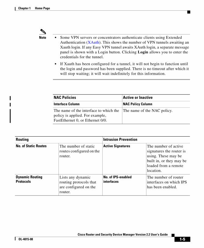
Note • Some VPN servers or concentrators authenticate clients using Extended Authentication (XAuth). This shows the number of VPN tunnels awaiting an Xauth login. If any Easy VPN tunnel awaits XAuth login, a separate message panel is shown with a Login button. Clicking Login allows you to enter the credentials for the tunnel.
• If Xauth has been configured for a tunnel, it will not begin to function until the login and password has been supplied. There is no timeout after which it will stop waiting; it will wait indefinitely for this information.
NAC Policies Active or Inactive
Interface Column NAC Policy Column
The name of the interface to which the policy is applied. For example, FastEthernet 0, or Ethernet 0/0.
The name of the NAC policy.
Routing Intrusion Prevention
No. of Static Routes The number of static routes configured on the router.
Active Signatures The number of active signatures the router is using. These may be built in, or they may be loaded from a remote location.
Dynamic Routing Protocols
Lists any dynamic routing protocols that are configured on the router.
No. of IPS-enabled interfaces
The number of router interfaces on which IPS has been enabled.
1-5Cisco Router and Security Device Manager Version 2.2 User’s Guide
OL-4015-08

Chapter 1 Home Page
1-6Cisco Router and Security Device Manager Version 2.2 User’s Guide
OL-4015-08

Cisco Router and Security DeOL-4015-08
C H A P T E R 2
LAN WizardThe Cisco Router and Security Device Manager (SDM) LAN wizard guides you in the configuration of a LAN interface. The screen lists the LAN interfaces on the router. You can select any of the interfaces shown in the window, and click Configure to make the interface a LAN interface and configure it.
This window lists the router interfaces that were designated as inside interfaces in Startup configuration, and lists the Ethernet interfaces and switch ports that have not been configured as WAN interfaces. The list includes interfaces that have already been configured.
When you configure an interface as a LAN interface, SDM inserts the description text $ETH-LAN$ in the configuration file so that it recognizes the interface as a LAN interface in the future.
Interface
The name of the interface.
Configure
Click this button to configure an interface you have selected. If the interface has not been configured before, SDM will take you through the LAN Wizard to help you configure it. If the interface has been given a configuration using SDM, SDM displays an Edit window enabling you to change configuration settings.
The Configure button may be disabled if a LAN interface has been given a configuration that SDM does not support. For a list of such configurations, see Reasons Why an Ethernet Interface Configuration May Be Read-Only.
2-1vice Manager Version 2.2 User’s Guide
Chapter 2 LAN WizardEthernet Configuration
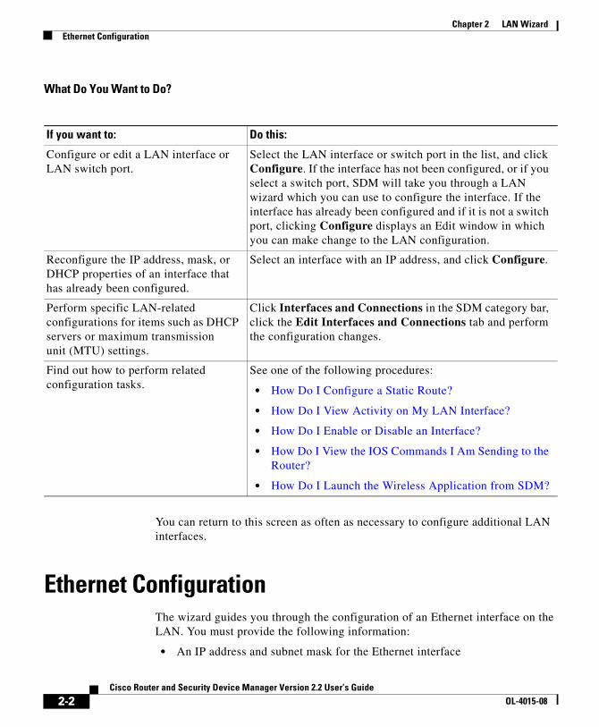
What Do You Want to Do?
You can return to this screen as often as necessary to configure additional LAN interfaces.
Ethernet ConfigurationThe wizard guides you through the configuration of an Ethernet interface on the LAN. You must provide the following information:
• An IP address and subnet mask for the Ethernet interface
If you want to: Do this:
Configure or edit a LAN interface or LAN switch port.
Select the LAN interface or switch port in the list, and click Configure. If the interface has not been configured, or if you select a switch port, SDM will take you through a LAN wizard which you can use to configure the interface. If the interface has already been configured and if it is not a switch port, clicking Configure displays an Edit window in which you can make change to the LAN configuration.
Reconfigure the IP address, mask, or DHCP properties of an interface that has already been configured.
Select an interface with an IP address, and click Configure.
Perform specific LAN-related configurations for items such as DHCP servers or maximum transmission unit (MTU) settings.
Click Interfaces and Connections in the SDM category bar, click the Edit Interfaces and Connections tab and perform the configuration changes.
Find out how to perform related configuration tasks.
See one of the following procedures:
• How Do I Configure a Static Route?
• How Do I View Activity on My LAN Interface?
• How Do I Enable or Disable an Interface?
• How Do I View the IOS Commands I Am Sending to the Router?
• How Do I Launch the Wireless Application from SDM?
2-2Cisco Router and Security Device Manager Version 2.2 User’s Guide
OL-4015-08

Chapter 2 LAN WizardLAN Wizard: Select an Interface
• A DHCP address pool if you decide to use DHCP on this interface
• The addresses of DNS and WINS servers on the WAN
• A domain name
LAN Wizard: Select an InterfaceSelect the interface on which you want to configure a LAN connection in this window. This window lists interfaces that can support Ethernet LAN configurations.
LAN Wizard: IP Address and Subnet MaskThis window lets you configure an IP address and subnet mask for the Ethernet interface that you chose in the first window.
IP Address
Enter the IP address for the interface in dotted decimal format. Your network administrator should determine the IP addresses of LAN interfaces. For more information, see IP Addresses and Subnet Masks.
Subnet Mask
Enter the subnet mask. Obtain this value from your network administrator. The subnet mask enables the router to determine how much of the IP address is used to define the network and host portions of the address.
Alternatively, select the number of network bits. This value is used to calculate the subnet mask. Your network administrator can tell you the number of network bits to enter.
2-3Cisco Router and Security Device Manager Version 2.2 User’s Guide
OL-4015-08

Chapter 2 LAN WizardLAN Wizard: Enable DHCP Server
LAN Wizard: Enable DHCP ServerThis screen lets you enable a DHCP server on your router. A DHCP server automatically assigns reusable IP addresses to the devices on the LAN. When a device becomes active on the network, the DHCP server grants it an IP address. When the device leaves the network, the IP address is returned to the pool for use by another device.
To enable a DHCP server on the router:
Click Yes.
LAN Wizard: DHCP Address PoolThis screen lets you configure the DHCP IP address pool. The IP addresses that the DHCP server assigns are drawn from a common pool that you configure by specifying the starting IP address in the range, and the ending address in the range.
For more information, see DHCP Address Pools.
Note If there are discontinuous address pools configured on the router, then the Starting IP and Ending IP address fields will be read-only.
Starting IP
Enter the beginning of the range of IP addresses for the DHCP server to use in assigning addresses to devices on the LAN. This is the lowest-numbered IP address in the range.
Ending IP
Enter the highest-numbered IP address in the range of IP addresses.
2-4Cisco Router and Security Device Manager Version 2.2 User’s Guide
OL-4015-08
Chapter 2 LAN WizardDHCP Options
DHCP OptionsUse this window to configure DHCP options that will be sent to hosts on the LAN that are requesting IP addresses from the router. These are not options for the router that you are configuring; these are parameters that will be sent to the requesting hosts on the LAN. To set these properties for the router, click Additional Tasks on the SDM category bar, click DHCP, and configure these settings in the DHCP Pools window.
DNS Server 1
The DNS server is typically a server that maps a known device name with its IP address. If you have DNS server configured for your network, enter the IP address for that device here.
DNS Server 2
If there is an additional DNS server on the network, you can enter the IP address for that server in this field.
Domain Name
The DHCP server that you are configuring on this router will provide services to other devices within this domain. Enter the name of the domain.
WINS Server 1
Some clients may require Windows Internet Naming Service (WINS) to connect to devices on the Internet. If there is a WINS server on the network, enter the IP address for the server in this field.
WINS Server 2
If there is an additional WINS server on the network, enter the IP address for the server in this field.
2-5Cisco Router and Security Device Manager Version 2.2 User’s Guide
OL-4015-08

Chapter 2 LAN WizardLAN Wizard: VLAN Mode
LAN Wizard: VLAN ModeThis screen lets you determine the type of VLAN information that will be carried over the switch port. Switch ports can be designated either to be in access mode, in which case they will forward only data that is destined for the VLAN to which they are assigned, or they can be designated to be in trunking mode, in which case they will forward data destined for all VLANs including the VLAN to which they are assigned.
If this switch port will be connected to a single device, such as a single PC or IP phone, or if this device will be connected to a port on a networking device, such as another switch, that is an access mode port, then select Single Device.
If this switch port will be connected to a port on a network device, such as another switch, that is a trunking mode, select Network Device.
LAN Wizard: Switch PortThis screen lets you assign an existing VLAN number to the switch port or to create a new VLAN interface to be assigned to the VLAN switch port.
Existing VLAN
If you want to assign the switch port to a VLAN that has already been defined, such as the default VLAN (VLAN 1), enter the VLAN ID number in the Network (VLAN) Identifier field.
New VLAN
If you want to create a new VLAN interface to which the switch port will be assigned, enter the new VLAN ID number in the New VLAN field, and then enter the IP address and subnet mask of the new VLAN logical interface in the IP Address and Subnet Mask fields.
2-6Cisco Router and Security Device Manager Version 2.2 User’s Guide
OL-4015-08

Chapter 2 LAN WizardIRB Bridge
Include this VLAN in an IRB bridge that will form a bridge with your wireless network. (Use Wireless Application to complete.)
If you check this box, the switch port will form part of a bridge with your wireless network. The other part of the bridge must be configured using the Wireless Application. The IP address and Subnet mask fields under New VLAN are disabled when this box is checked.
After completing this LAN configuration, do the following to launch the Wireless Application and complete the bridging configuration.
Step 1 Select Wireless Application from the SDM Tools menu. The Wireless Application opens in a separate browser window.
Step 2 In the Wireless Application, click Wireless Express Security, and then click Bridging to provide the information to complete the bridging configuration.
IRB BridgeIf you are configuring a VLAN to be part of an IRB bridge, the bridge must be a member of a bridge group.
To create a new bridge group that this interface will be part of, click Create a new bridge group and enter a value in the range 1 through 255.
To have this VLAN be a member of an existing bridge group, click Join an existing bridge group, and select a bridge group.
Note When you complete the bridge configuration in the Wireless Application, you must use the same bridge group number entered in this screen.
BVI ConfigurationAssign an IP address and subnet mask to the BVI interface. If you selected an existing bridge group in the previous screen, the IP address and subnet mask will appear in this screen. You can change it, or leave the values unchanged.
2-7Cisco Router and Security Device Manager Version 2.2 User’s Guide
OL-4015-08
Chapter 2 LAN WizardDHCP Pool for BVI
IP Address
Enter the IP address for the interface in dotted decimal format. Your network administrator should determine the IP addresses of LAN interfaces. For more information, see IP Addresses and Subnet Masks.
Net Mask
Enter the subnet mask. Obtain this value from your network administrator. The subnet mask enables the router to determine how much of the IP address is used to define the network and host portions of the address.
Net Bits
Alternatively, select the number of network bits. This value is used to calculate the subnet mask. Your network administrator can tell you the number of network bits to enter.
DHCP Pool for BVIWhen you configure the router as a DHCP server, you can create a pool of IP addresses that clients on the network can use. When a client logs off the network, the address it was using is returned to the pool for use by another host.
DHCP Server Configuration
Click this box if you want to have the router function as a DHCP server. Then, specify the starting and ending IP addresses in the pool. Be sure to specify IP addresses in the same subnet as the IP address you gave the interface. For example, If you gave the interface an IP address of 10.10.22.1, with a subnet mask of 255.255.255.0, you have over 250 addresses available for the pool, and you might specify a Start IP Address of 10.10.22.2, and an End IP Address of 10.10.22.253.
2-8Cisco Router and Security Device Manager Version 2.2 User’s Guide
OL-4015-08
Chapter 2 LAN WizardIRB for Ethernet
IRB for EthernetIf your router has a wireless interface, you can use Integrated Routing and Bridging to have this interface form part of a bridge to the wireless LAN, and enable traffic destined for the wireless network to be routed through this interface. Click Yes if you want to configure this Layer 3 interface for Integrated Routing and Bridging.
If you do not want this interface to be used in bridge to the wireless interface, click No. You will still be able to configure it as a regular routing interface.
Layer 3 Ethernet ConfigurationSDM supports Layer 3 Ethernet configuration on routers with installed 3750 switch modules. You can create VLAN configurations and designate router Ethernet interfaces as DHCP servers.
802.1Q ConfigurationYou can configure a VLAN that does not use the 802.1Q encapsulation protocol used for trunking connections. Provide a VLAN ID number, and check Native VLAN if you do not want the VLAN to use 802.1Q tagging.
If you want to use the 802.1Q tagging, leave the Native VLAN box unchecked.
Trunking or Routing ConfigurationYou can configure Layer 3 Ethernet interfaces for 802.1Q trunking or for basic routing. If you configure the interface for 802.1Q trunking, you can configure VLANs on the interface, and you can configure a native VLAN that does not use the 802.1q encapsulation protocol. I f you configure the interface for routing, you cannot configure subinterfraces or additional VLANs on the interface.
2-9Cisco Router and Security Device Manager Version 2.2 User’s Guide
OL-4015-08

Chapter 2 LAN WizardSummary
Configure Switch Device ModuleIf you are configuring a Gigabit Ethernet interface for routing, you can provide information about the switch module in this window. It is not required that you provide this information.
You can provide an IP address and subnet mask for the switch module, and login credentials required to log on to the the switch module interface.
Check the box at the bottom of the screen if you want to log on to the switch module after providing the information in this wizard and delivering the configuration to the router.
SummaryThis window provides a summary of the configuration changes that you made for the interface you selected.
To save this configuration to the router’s running configuration and leave this wizard:
Click Finish. SDM saves the configuration changes to the router’s running configuration. Although the changes take effect immediately, they will be lost if the router is turned off.
If you checked Preview commands before delivering to router in the User Preferences window, the Deliver window appears. In this window you can view the CLI commands that you are delivering to the router.
How Do I...This section contains procedures for tasks that the wizard does not help you complete.
How Do I Configure a Static Route?To configure a static route:
2-10Cisco Router and Security Device Manager Version 2.2 User’s Guide
OL-4015-08

Chapter 2 LAN WizardHow Do I...
Step 1 From the category bar, click Routing.
Step 2 In the Static Routing group, click Add....
The Add IP Static Route dialog box appears.
Step 3 In the Prefix field, enter the IP address of the static route destination network.
Step 4 In the Prefix Mask field, enter the subnet mask of the destination network.
Step 5 If you want this static route to be the default route, check the Make this as the Default Route check box.
Step 6 In the Forwarding group, select whether to identify a router interface or the destination router IP address as the method to forward data, and then choose either the forwarding router interface or enter the destination router IP address.
Step 7 Optionally, in the Distance Metric field, enter the distance metric to be stored in the routing table.
Step 8 If you want to configure this static route to be a permanent route, which means that it will not be deleted even if the interface is shut down or the router is unable to communicate with the next router, check the Permanent Route check box.
Step 9 Click OK.
How Do I View Activity on My LAN Interface?You can view activity on a LAN interface by using the Monitor mode in SDM. Monitor mode can display statistics about the LAN interface, including the number of packets and bytes that have been sent or received by the interface, and the number of send or receive errors that have occurred. To display statistics about about a LAN interface:
Step 1 From the toolbar, click Monitor.
Step 2 From the left frame, click Interface Status.
Step 3 In the Select an Interface field, select the LAN interface for which you want to view statistics.
Step 4 Select the data item(s) you want to view by checking the associated check box(es). You can view up to four statistics at a time.
2-11Cisco Router and Security Device Manager Version 2.2 User’s Guide
OL-4015-08

Chapter 2 LAN WizardHow Do I...
Step 5 Click Start Monitoring to see statistics for all selected data items.
The Interface Details screen appears, displaying the statistics you selected. The screen defaults to showing real-time data, for which it polls the router every 10 seconds. If the interface is up and there is data transmitting across it, you should see an increase in the number of packets and bytes transferred across the interface.
How Do I Enable or Disable an Interface?You can disable an interface without removing its configuration, and you can reenable an interface that you have disabled.
Step 1 Click Interfaces and Connections in the category bar.
Step 2 Click the Edit Interfaces and Connections tab.
Step 3 Select the interface that you want to disable or enable.
Step 4 If the interface is enabled, the Disable button appears below the Interface List. Click that button to disable the interface. If the interface is currently disabled, the Enable button appears below the Interface List. Click that button to disable the interface.
How Do I View the IOS Commands I Am Sending to the Router?If you are completing a Wizard to configure a feature, you can view the Cisco IOS commands that you are sending to the router when you click Finish.
Step 1 From the SDM Edit menu, select Preferences.
Step 2 Check Preview commands before delivering to router.
Step 3 Click OK.
2-12Cisco Router and Security Device Manager Version 2.2 User’s Guide
OL-4015-08

Chapter 2 LAN WizardHow Do I...
The next time you use a wizard to configure the router and click Finish on the Summary window, the Deliver window will appear. In this window you can view the commands that you are delivering to the router’s configuration. Click Deliver when you are finished reviewing the commands.
If you are editing a configuration, the Deliver window is displayed when you click OK in the dialog window. In this window you can view the Cisco IOS commands that you are sending to the router .
How Do I Launch the Wireless Application from SDM?Use the following procedure to launch the wireless application from SDM.
Step 1 Go to the SDM Tools menu and select Wireless Application. The Wireless Application launches in a separate browser window.
Step 2 In the left panel, click the title of the configuration screen that you want to work in. To obtain help for any screen, click the help icon in the upper right corner. This icon looks like an open book with a question mark.
2-13Cisco Router and Security Device Manager Version 2.2 User’s Guide
OL-4015-08

Chapter 2 LAN WizardHow Do I...
2-14Cisco Router and Security Device Manager Version 2.2 User’s Guide
OL-4015-08
Cisco Router and Security DeOL-4015-08
C H A P T E R 3
Create Connection WizardsThe Create Connection wizards let you configure LAN and WAN connections for all SDM-supported interfaces.
Create ConnectionThis window allows you to create new LAN and WAN connections.
Note You cannot use SDM to create WAN connections for Cisco 7000 series routers.
Create a New Connection
Choose a connection type in this area of the window. The types shown are based on the types of physical interfaces on the router and on which interfaces have not yet been configured. When you click a radio button for a connection type, a use case scenario diagram appears to the right illustrating that type of connection. If all interfaces have been configured, this area is not displayed.
If the router has Asynchronous Transfer Mode (ATM) or Serial interfaces, multiple connections can be configured from a single interface because Cisco Router and Security Device Manager (SDM) configures subinterfaces for each interface of that type.
3-1vice Manager Version 2.2 User’s Guide

Chapter 3 Create Connection WizardsWAN Wizard Interface Welcome Window
The Other (Unsupported by SDM) radio button appears if an unsupported logical or physical interface exists, or if a supported interface exists that has been given an unsupported configuration. When you click this radio button, Create New Connection is disabled, and a reason for the Other radio button appearing is given in the Information box.
If the router has radio interfaces but you do not see a Wireless radio button, you are not logged on as an SDM Administrator. If you need to use the Wireless Application, go to the SDM Tools menu, and select Wireless Application.
What Do You Want to Do?
WAN Wizard Interface Welcome WindowThis window lists the types of connections you can configure for this interface using SDM. If you need to configure another type of connection for this interface, you can do so using the CLI.
If you want to: Do this:
Learn how to perform configurations that this wizard does not help you with.
See one of the following procedures:
• How Do I View the IOS Commands I Am Sending to the Router?
• How Do I Configure an Unsupported WAN Interface?
• How Do I Enable or Disable an Interface?
• How Do I View Activity on My WAN Interface?
• How Do I Configure NAT on a WAN Interface?
• How Do I Configure a Static Route?
• How Do I Configure a Dynamic Routing Protocol?
• How Do I Configure Dial-on-Demand Routing for my ISDN or Asynchronous Interface?
Configure an interface that SDM does not support.
Refer to the software configuration guide for the router to use the CLI to configure the interface.
3-2Cisco Router and Security Device Manager Version 2.2 User’s Guide
OL-4015-08
Chapter 3 Create Connection WizardsISDN Wizard Welcome Window
ISDN Wizard Welcome WindowPPP is the only type of encoding supported over ISDN BRI by SDM.
Analog Modem Welcome WindowPPP is the only type of encoding supported over an analog modem connection by SDM.
Aux Backup Welcome WindowThe option to configure the AUX port as a dial-up connection will only be shown for the Cisco 831 and 837 routers.
The Aux dial-backup radio button is disabled if any of the following conditions occur:
• When more than one default route exists
• When one default route exists and the same is configured with interface other than the primary WAN interface
The Aux dial-backup option will not be shown if any of the following conditions occur:
• When the router is not using a Cisco IOS image that supports the Aux dial-backup feature.
• When a primary WAN interface is not configured
• When the asynchronous interface is already configured
• When the asynchronous interface is not configurable by SDM due to the presence of unsupported Cisco IOS commands in the existing configuration
3-3Cisco Router and Security Device Manager Version 2.2 User’s Guide
OL-4015-08
Chapter 3 Create Connection WizardsSelect Interface
Select InterfaceThis window appears if there are more than one interface of the type you selected in the Create Connection window. Choose the interface that you want to use for this connection.
If you are configuring an Ethernet interface, SDM inserts the description text $ETH-WAN$ in the configuration file so that it will recognize the interface as a WAN interface in the future.
Encapsulation: PPPoEThis window lets you enable Point-to-Point-Protocol over Ethernet (PPPoE) encapsulation. This is necessary if your service provider or network administrator requires remote routers to communicate using PPPoE.
PPPoE is a protocol used by many asymmetric digital subscriber line (ADSL) service providers. Ask your service provider if PPPoE is used over your connection.
If you choose PPPoE encapsulation, SDM automatically adds a dialer interface to the configuration, and this is shown in the Summary window.
Enable PPPoE Encapsulation
If your service provider requires that the router use PPPoE, check this box to enable PPPoE encapsulation. Uncheck this box if your service provider does not use PPPoE. This check box will not be available if your router is running a version of Cisco IOS that does not support PPPoE encapsulation.
IP Address: ATM or Ethernet with PPPoE/PPPoAChoose the method that the WAN interface will use to obtain an IP address.
Static IP Address
If you choose static IP address, enter the IP address and subnet mask or the network bits in the fields provided.
3-4Cisco Router and Security Device Manager Version 2.2 User’s Guide
OL-4015-08

Chapter 3 Create Connection WizardsIP Address: ATM with RFC 1483 Routing
Dynamic (DHCP Client)
If you choose Dynamic, the router will lease an IP address from a remote DHCP server. Enter the name of the DHCP server that will assign addresses.
IP Unnumbered
Select IP Unnumbered if you want the interface to share an IP address that has already been assigned to another interface. Then, choose the interface whose IP address you want the interface that you are configuring to use.
Easy IP (IP Negotiated)
Select Easy IP (IP Negotiated) if the router will obtain an IP address via PPP/IPCP address negotiation.
Dynamic DNS
Enable dynamic DNS if you want to automatically update your DNS servers whenever the WAN interface’s IP address changes. Click the Dynamic DNS button to configure dynamic DNS.
IP Address: ATM with RFC 1483 RoutingChoose the method that the WAN interface will use to obtain an IP address.
Static IP Address
If you choose Static IP Address, enter the IP address and subnet mask or the network bits in the fields provided. For more information, refer to IP Addresses and Subnet Masks.
Dynamic (DHCP Client)
If you choose Dynamic, the router will lease an IP address from a remote DHCP server. Enter the name of the DHCP server that will assign addresses.
3-5Cisco Router and Security Device Manager Version 2.2 User’s Guide
OL-4015-08

Chapter 3 Create Connection WizardsIP Address: Ethernet without PPPoE
IP Unnumbered
Click IP Unnumbered if you want the interface to share an IP address that has already been assigned to another interface. Then, choose the interface whose IP address you want the interface that you are configuring to use.
Dynamic DNS
Enable dynamic DNS if you want to automatically update your DNS servers whenever the WAN interface’s IP address changes. Click the Dynamic DNS button to configure dynamic DNS.
IP Address: Ethernet without PPPoEChoose the method that the WAN interface will use to obtain an IP address.
Static IP Address
If you choose Static IP Address, enter the IP address and subnet mask or the network bits in the fields provided. For more information, refer to IP Addresses and Subnet Masks.
Dynamic (DHCP Client)
If you choose Dynamic, the router will lease an IP address from a remote DHCP server. Enter the name of the DHCP server that will assign addresses.
Dynamic DNS
Enable dynamic DNS if you want to automatically update your DNS servers whenever the WAN interface’s IP address changes. Click the Dynamic DNS button to configure dynamic DNS.
IP Address: Serial with Point-to-Point ProtocolChoose the method that the point-to-point interface will use to obtain an IP address.
3-6Cisco Router and Security Device Manager Version 2.2 User’s Guide
OL-4015-08

Chapter 3 Create Connection WizardsIP Address: Serial with HDLC or Frame Relay
Static IP Address
If you choose static IP address, enter the IP address and subnet mask or the network bits in the fields provided. For more information, refer to IP Addresses and Subnet Masks.
IP Unnumbered
Select IP Unnumbered if you want the interface to share an IP address that has already been assigned to another interface. Then, choose the interface whose IP address you want the interface that you are configuring to use.
Easy IP (IP Negotiated)
Select Easy IP (IP Negotiated) if the router will obtain an IP address via PPP/IPCP address negotiation.
Dynamic DNS
Enable dynamic DNS if you want to automatically update your DNS servers whenever the WAN interface’s IP address changes. Click the Dynamic DNS button to configure dynamic DNS.
IP Address: Serial with HDLC or Frame RelayChoose the method that the WAN interface will use to obtain an IP address. If Frame Relay encapsulation is used, SDM creates a subinterface, and the IP address is assigned to the subinterface SDM creates.
Static IP Address
If you choose static IP address, enter the IP address and subnet mask or the network bits in the fields provided. For more information, refer to IP Addresses and Subnet Masks.
3-7Cisco Router and Security Device Manager Version 2.2 User’s Guide
OL-4015-08
Chapter 3 Create Connection WizardsIP Address: ISDN BRI or Analog Modem
IP Unnumbered
Select IP Unnumbered if you want the interface to share an IP address that has already been assigned to another interface. Then, choose the interface whose IP address you want the interface that you are configuring to use.
Dynamic DNS
Enable dynamic DNS if you want to automatically update your DNS servers whenever the WAN interface’s IP address changes. Click the Dynamic DNS button to configure dynamic DNS.
IP Address: ISDN BRI or Analog ModemChoose the method that the ISDN BRI or analog modem interface will use to obtain an IP address.
Static IP Address
If you choose Static IP Address, enter the IP address and subnet mask or the network bits in the fields provided. For more information, refer to IP Addresses and Subnet Masks.
IP Unnumbered
Select IP Unnumbered if you want the interface to share an IP address that has already been assigned to another interface. Then, choose the interface that has the IP address that you want the interface that you are configuring to use.
Easy IP (IP Negotiated)
Select IP Negotiated if the interface will obtain an IP address from your ISP via PPP/IPCP address negotiation whenever a connection is made.
Dynamic DNS
Enable dynamic DNS if you want to automatically update your DNS servers whenever the WAN interface’s IP address changes. Click the Dynamic DNS button to configure dynamic DNS.
3-8Cisco Router and Security Device Manager Version 2.2 User’s Guide
OL-4015-08

Chapter 3 Create Connection WizardsAuthentication
AuthenticationThis page is displayed if you enabled PPP for a serial connection, PPPoE or PPPoA encapsulation for an ATM or Ethernet connection, or if you are configuring an ISDN BRI or analog modem connection. Your service provider or network administrator may use a Challenge Handshake Authentication Protocol (CHAP) password or a Password Authentication Protocol (PAP) password to secure the connection between the devices. This password secures both incoming and outgoing access.
Authentication Type
Check the box for the type of authentication used by your service provider. If you do not know which type your service provider uses, you can check both boxes: the router will attempt both types of authentication, and one attempt will succeed.
CHAP authentication is more secure than PAP authentication.
Username
The username is given to you by your Internet service provider or network administrator and is used as the username for CHAP/PAP authentication.
Password
Enter the password exactly as given to you by your service provider. Passwords are case sensitive. For example, the password cisco is not the same as Cisco.
Confirm Password
Reenter the same password that you entered in the previous box.
Switch Type and SPIDsISDN BRI connections require identification of the ISDN switch type, and in some cases, identification of the B channels using Service Provider ID (SPID) numbers. This information will be provided to you by your service provider.
3-9Cisco Router and Security Device Manager Version 2.2 User’s Guide
OL-4015-08
Chapter 3 Create Connection WizardsSwitch Type and SPIDs
ISDN Switch Type
Select the ISDN switch type. Contact your ISDN service provider for the switch type for your connection.
SDM supports these BRI switch types:
• For North America:
– basic-5ess—Lucent (AT&T) basic rate 5ESS switch
– basic-dms100—Northern Telecom DMS-100 basic rate switch
– basic-ni—National ISDN switches
• For Australia, Europe, and the UK:
– basic-1tr6—German 1TR6 ISDN switch
– basic-net3—NET3 ISDN BRI for Norway NET3, Australia NET3, and New Zealand NET3switch types; ETSI-compliant switch types for Euro-ISDN E-DSS1 signaling system
– vn3—French ISDN BRI switches
• For Japan:
– ntt—Japanese NTT ISDN switches
• For voice/PBX systems:
– basic-qsig—PINX (PBX) switches with QSIG signaling per Q.931
I Have SPIDs
Check this check box if your service provider requires SPIDs.
Some service providers use SPIDs to define the services that are subscribed to by an ISDN device that is accessing the ISDN service provider. The service provider assigns the ISDN device one or more SPIDs when you first subscribe to the service. If you are using a service provider that requires SPIDs, your ISDN device cannot place or receive calls until it sends a valid, assigned SPID to the service provider when the device accesses the switch to initialize the connection.
Currently, only the DMS-100 and NI switch types require SPIDs. The AT&T 5ESS switch type may support a SPID, but we recommend that you set up the ISDN service without SPIDs. In addition, SPIDs have significance only at the local access ISDN interface. Remote routers never receive the SPID.
3-10Cisco Router and Security Device Manager Version 2.2 User’s Guide
OL-4015-08

Chapter 3 Create Connection WizardsDial String
A SPID is usually a 7-digit telephone number with some optional numbers. However, service providers may use different numbering schemes. For the DMS-100 switch type, two SPIDs are assigned, one for each B channel.
SPID1
Enter the SPID for the first BRI B channel provided to you by your ISP.
SPID2
Enter the SPID for the second BRI B channel provided to you by your ISP.
Dial StringEnter the phone number of the remote end of the ISDN BRI or analog modem connection. This is the phone number that the ISDN BRI or analog modem interface will dial whenever a connection is made. The dial string is provided to you by your service provider.
Backup ConfigurationISDN BRI and analog modem interfaces can be configured to work as backup interfaces to other, primary interfaces. In that case, an ISDN or analog modem connection will be made only if the primary interface goes down for some reason. If the primary interface and connection goes down, the ISDN or analog modem interface will immediately dial out and try to establish a connection so that network services are not lost.
Select whether this ISDN BRI or analog modem connection should act as a backup connection.
Note the following prerequisites:
• The primary interface must be configured for Site-to-Site VPN.
• The IOS image on your router must support the SAA ICMP Echo Enhancement feature.
3-11Cisco Router and Security Device Manager Version 2.2 User’s Guide
OL-4015-08

Chapter 3 Create Connection WizardsBackup Configuration
Backup Configuration: Primary Interface & Next Hop IP Addresses
In order for the ISDN BRI or analog modem connection to act as a backup connection, it must be associated with another interface on the router that will act as the primary connection. The ISDN BRI or analog modem connection will be made only if the connection on the primary interface goes down.
Primary Interface
Select the router interface that will maintain the primary connection.
Primary Next Hop IP Address
This field is optional. Enter the IP address to which the primary interface will connect when it is active, known as the next hop IP address.
Backup Next Hop IP Address
This field is optional. Enter the IP address to which the backup interface will connect when it is active, known as the next hop IP address.
Backup Configuration: Hostname or IP Address to be TrackedThis screen lets you identify a specific host to which connectivity must be maintained. The router will track connectivity to that host, and if the router discovers that connectivity has been lost by the primary interface, a backup connection will be initiated over the ISDN BRI or analog modem interface.
IP Address to be Tracked
Enter the IP address or host name of the destination host to which connectivity will be tracked. Please specify an infrequently-contacted destination as the site to be tracked.
3-12Cisco Router and Security Device Manager Version 2.2 User’s Guide
OL-4015-08

Chapter 3 Create Connection WizardsAdvanced Options
Advanced OptionsThere are two advanced options available, based on the router’s configuration: Default static route, and Port Address Translation (PAT). If the Static Route option is not visible in the window, a static route has already been configured on the router. If the PAT option is not visible, PAT has already been configured on an interface.
Default Static Route
Check this box if you want to configure a static route to the outside interface to which outgoing traffic will be routed. If a static route has already been configured on this router, this box will not appear.
Next Hop Address
If your service provider has given you a next hop IP address to use, enter the IP address in this field. If you leave this field blank, SDM will use the WAN interface that you are configuring as the next-hop interface.
Port Address Translation
If devices on the LAN have private addresses, you can allow them to share a single public IP address. You can ensure that traffic goes to its proper destination by using PAT, which represents hosts on a LAN with a single IP address and uses different port numbers to distinguish the hosts. If PAT has already been configured on an interface, the PAT option will not be visible.
Inside Interface to be Translated
Choose the inside interface connected to the network whose host IP addresses you want to be translated.
EncapsulationIn this window, select the type of encapsulation that the WAN link will use. Ask your service provider or network administrator which type of encapsulation is used for this link. The interface type determines the types of encapsulation available.
3-13Cisco Router and Security Device Manager Version 2.2 User’s Guide
OL-4015-08
Chapter 3 Create Connection WizardsEncapsulation
Autodetect
Click Autodetect to have SDM discover the encapsulation type. If SDM succeeds, it will automatically supply the encapsulation type and other configuration parameters it discovers.
Note SDM supports autodetect on SB106, SB107, Cisco 836 and Cisco 837 routers. However if you are configuring a Cisco 837 router and the router is running an IOS image of version 12.3(8)T or version 12.3(8.3)T, the autodetect feature is not supported.
Available Encapsulations
The encapsulations available if you have an ADSL, G.SHDSL, or ADSL over ISDN interface are shown in the following table.
Encapsulation Description
PPPoE Provides Point-to-Point Protocol over Ethernet encapsulation. This option is available when you have selected an Ethernet interface or an ATM interface. An ATM subinterface and a dialer interface will be created when you configure PPPoE over an ATM interface.
The PPPoE radio button will be disabled if your router is running a version of Cisco IOS that does not support PPPoE encapsulation.
PPPoA Point-to-Point protocol over ATM. This option is available when you have selected an ATM interface. An ATM subinterface and a dialer interface will be created when you configure PPPoA over an ATM interface.
The PPPoA radio button will be disabled if your router is running a version of Cisco IOS that does not support PPPoA encapsulation.
RFC 1483 routing with AAL5-SNAP
This option is available when you have selected an ATM interface. An ATM subinterface will be created when you configure an RFC 1483 connection. This subinterface will be visible in the Summary window.
RFC 1483 routing with AAL5-MUX
This option is available when you have selected an ATM interface. An ATM subinterface will be created when you configure an RFC 1483 connection. This subinterface will be visible in the Summary window.
3-14Cisco Router and Security Device Manager Version 2.2 User’s Guide
OL-4015-08
Chapter 3 Create Connection WizardsPVC
The encapsulations available if you have a serial interface are shown in the following table.
PVCATM routing uses a two-layer hierarchical scheme, virtual paths, and virtual channels, denoted by the virtual path identifier (VPI) and virtual channel identifier (VCI), respectively. A particular virtual path may carry a number of different virtual channels corresponding to individual connections. When switching is performed based on the VPI, all cells on that particular virtual path are switched regardless of the VCI. An ATM switch may route according to VCI, VPI, or both VCI and VPI.
VPI
Enter the VPI value obtained from your service provider or system administrator. The virtual path identifier (VPI) is used in ATM switching and routing to identify the path used for a number of connections. Enter the VPI value given to you by your service provider.
Encapsulation Description
Frame Relay Provides Frame Relay encapsulation. This option is available when you have selected a serial interface. A serial subinterface will be created when you create a Frame Relay connection. This subinterface will be visible in the Summary window.
Note If a Frame Relay serial connection has been added to an interface, only Frame Relay encapsulation will be enabled in this window when subsequent Serial connections are configured on the same interface.
Point-to-Point Protocol Provides PPP encapsulation. This option is available when you have selected a serial interface.
High Level Data Link Control Provides HDLC encapsulation. This option is available when you have selected a serial interface.
3-15Cisco Router and Security Device Manager Version 2.2 User’s Guide
OL-4015-08

Chapter 3 Create Connection WizardsConfigure LMI and DLCI
VCI
Enter the VCI value obtained from your service provider or system administrator. The virtual circuit identifier (VCI) is used in ATM switching and routing to identify a particular connection within a path that it may share with other connections. Enter the VCI value given to you by your service provider.
Cisco IOS Default Values
The values shown in the following table are Cisco IOS defaults. SDM will not overwrite these values if they have been changed during a prior configuration, but if your router has not been previously configured, these are the values that will be used:
Configure LMI and DLCIIf you are configuring a connection with Frame Relay encapsulation, you must specify the protocol used to monitor the connection, called the Local Management Identifier (LMI), and provide a unique identifier for this particular connection, called a data link connection identifier (DLCI).
LMI Type
Ask your service provider which of the following LMI types you should use.
Connection Type Parameter Value
ADSL • Operating mode • Auto
G.SHDSL • Operating mode
• Line Rate
• Equipment type
• Annex A (U.S.).
• Auto
• CPE
ADSL over ISDN
• Operating mode • Auto
3-16Cisco Router and Security Device Manager Version 2.2 User’s Guide
OL-4015-08

Chapter 3 Create Connection WizardsConfigure Clock Settings
DLCI
Enter the DLCI in this field. This number must be unique among all DLCIs used on this interface.
Use IETF Frame Relay Encapsulation
Internet Engineering Task Force (IETF) encapsulation. This option is used with connecting to non-Cisco routers. Check this box if you are connecting to a non_Cisco router on this interface.
Configure Clock SettingsThe Clock Settings window is available when you are configuring a T1 or E1 link. The default Frame Relay clock settings are shown in this page. You should not change them unless you know you have different requirements.
Clock Source
Internal specifies that the clock be generated internally. Line specifies that the clock source be taken from the network. The clock synchronizes data transmission. The default is line.
LMI Type Description
ANSI Annex D defined by American National Standards Institute (ANSI) standard T1.617.
Cisco LMI type defined jointly by Cisco Systems and three other companies.
ITU-T Q.933 ITU-T Q.933 Annex A.
Autosense The default. This setting allows the router to detect which LMI type is being used by communicating with the switch and to then use that type. If autosense fails, the router will use the Cisco LMI type.
3-17Cisco Router and Security Device Manager Version 2.2 User’s Guide
OL-4015-08
Chapter 3 Create Connection WizardsConfigure Clock Settings
T1 Framing
This field configures the T1 or E1 link for operation with D4 Super Frame (sf) or Extended Superframe (esf). The default is esf.
Line Code
This field configures the router for operation on binary 8-zeroes substitution (B8ZS) or alternate mark inversion (AMI) T1 lines. The b8zs setting ensures density on a T1 or E1 line by substituting intentional bipolar violations in bit positions 4 and 7 for a sequence of eight zero bits. When the router is configured with the ami setting, you must guarantee density in your router configuration with the data-coding inverted setting. The default is b8zs.
Data Coding
Click inverted if you know that user data is inverted on this link, or if Line Code is set to AMI. Otherwise leave this set to the default value normal. Data inversion is used with bit-oriented protocols such as HDLC, PPP, and Link Access Procedure, Balanced (LAPB) to ensure density on a T1 line with AMI encoding. These bit-oriented protocols perform zero insertions after every five “one” bits in the data stream. This has the effect of ensuring at least one zero in every eight bits. If the data stream is then inverted, it ensures that at least one out of every eight bits is a one.
If you do not want to use inverted data coding with the AMI line code, you must use the CLI to configure all time slots to 56 kbps. SDM will set data coding to inverted if the line code is AMI and there are no time slots configured for 56 kbps.
Facilities Data Link (FDL)
This field configures the router behavior on the Facilities Data Link (FDL) of the Extended Superframe. When configured with att, the router implements AT&T TR 54016. When configured with ansi, it implements ANSI T1.403. When you choose both, the router implements both att and ansi choices.When you choose none, the router ignores the FDL. The default is none. If T1 or E1 framing is set to sf, SDM will set FDL to none and make this field read-only.
3-18Cisco Router and Security Device Manager Version 2.2 User’s Guide
OL-4015-08

Chapter 3 Create Connection WizardsDelete Connection
Line Build Out (LBO)
This field is used to configure the Line Build Out (LBO) of the T1 link. The LBO decreases the transmit strength of the signal by -7.5 or -15 decibels. It is not likely to be needed on actual T1 or E1 lines. The default is none.
Remote Loopback Requests
This field specifies whether the router will go into loopback when a loopback code is received on the line. Choosing full will cause the router to accept full loopbacks, and choosing payload-v54 will cause the router to select payload loopbacks.
Enable Generation/Detection of Remote Alarms
Check this box if you want the router T1 link to generate remote alarms (yellow alarms) and to detect remote alarms being sent from the peer on the other end of the link.
The remote alarm is transmitted by a router when it detects an alarm condition: either a red alarm (loss of signal) or a blue alarm (unframed 1s). The receiving channel service unit/ data service unit (CSU/DSU) then knows that there is an error condition on the line.
This setting should only be used when T1 framing is set to esf.
Delete ConnectionYou can delete a WAN connection that appears in the Edit Interface/Connections window. This window appears when you are deleting an interface configuration, and when the connection you want to delete contains associations such as Access Rules that have been applied to this interface. This window gives you the opportunity to save the associations for use with another connection.
When you delete a connection, the Create New Connection list is refreshed if the deletion makes a connection type available that was not available before the deletion.
You can automatically delete all associations that the connection has, or delete the associations later.
3-19Cisco Router and Security Device Manager Version 2.2 User’s Guide
OL-4015-08

Chapter 3 Create Connection WizardsDelete Connection
To view the associations that the connection has:
Click View Details.
To delete the connection and all associations:
Click Automatically delete all associations, and then click OK to cause SDM to delete the connection and all of the associations.
To manually delete the association:
To manually delete the associations, click View Details to see a list of the associations that this connection has. Make note of the associations, then select I will delete the associations later, and then click OK. You must then delete the associations that the connection has, following the instructions in following list.
The possible associations, and the instructions for deleting them, are:
• Default Static Route—The interface is configured as the forwarding interface for a default static route. To delete the static route with which this interface is associated, click Configure; then click Routing. Click the static route in the Static Routing table, and click Delete.
• Port Address Translation—PAT is configured, using the interface on which this connection was created. To delete the PAT association, click Configure; then click NAT. Click the rule associated with this connection, and click Delete.
• NAT—The interface is designated as either a NAT inside or NAT outside interface. To delete the NAT association, click Configure; then click Interfaces and Connections. Click the connection in the Interface List, then click Edit. Click the NAT tab, then from the NAT pulldown, choose None.
• ACL—An ACL is applied to the interface on which the connection was created. To delete the ACL, click Configure; then click Interfaces and Connections. Click the connection in the Interface List; then click Edit. Click the Association tab, then in the Access Rule group, click the ... button next to both the Inbound and Outbound fields, and click None.
• Inspect—An inspection rule is applied to the interface on which the connection was created. To delete the inspection rule, click Configure; then click Interfaces and Connections. Click the connection in the Interface List, then click Edit. Click the Association tab; then in the Inspection Rule group, in both the Inbound and Outbound fields, choose None.
3-20Cisco Router and Security Device Manager Version 2.2 User’s Guide
OL-4015-08

Chapter 3 Create Connection WizardsSummary
• Crypto—A crypto map is applied to the interface on which the connection was created. To delete the crypto map, click Configure; then click Interfaces and Connections. Click the connection in the Interface List, then click Edit. Click the Association tab; then in the VPN group, in the IPSec Policy field, click None.
• EZVPN—An Easy VPN is applied to the interface on which the connection was created. To delete the Easy VPN, click Configure; then click Interfaces and Connections. Click the connection in the Interface List, then click Edit. Click the Association tab; then in the VPN group, in the Easy VPN field, click None.
• VPDN—VPDN commands that are required for a PPPoE configuration are present in the router configuration. If there are any other PPPoE connections configured on the router, do not delete the VPDN commands.
• ip tcp adjust mss—This command is applied to a LAN interface to adjust the TCP maximum size. If there are any other PPPoE connections configured on the router, do not delete this command.
• Backup connection—When a backup connection is configured for the primary interface.To delete the backup association, click Configure, then click Interfaces and Connections. Click the Backup interface in the Interface List, then click Edit. Click the Backup tab; uncheck the Enable Backup check box.
• PAT on Backup connection—PAT is configured on the backup interface. To delete the PAT association, click Configure; then click NAT. Click the rule associated with this connection, and then click Delete.
• Floating Default Route on Backup connection—The Backup interface is configured with a floating default static route. To delete the floating static route , click Configure; then click Routing. Click the floating static route in the Static Routing table, and click Delete.
Summary This screen displays a summary of the WAN link that you configured.You can review this information, and if you need to change anything, you can click the Back button to return to the screen on which you need to make changes.
3-21Cisco Router and Security Device Manager Version 2.2 User’s Guide
OL-4015-08

Chapter 3 Create Connection WizardsConnectivity testing and troubleshooting
Test the connectivity after configuring
Check this box if you want SDM to test the connection you have configured after it delivers the commands to the router. SDM will test the connection and report results in another window.
To save this configuration to the router’s running configuration and leave this wizard:
Click Finish. SDM saves the configuration changes to the router’s running configuration. The changes will take effect immediately, but will be lost if the router is turned off.
If you checked Preview commands before delivering to router in the SDM Preferences window, the Deliver window appears. In this window, you can view the CLI commands that you are delivering to the router.
Connectivity testing and troubleshootingThis window allows you to test a configured connection by pinging a remote host. If the ping fails, SDM reports the probable cause and suggests actions you can take to correct the problem.
Which connection types can be tested?
SDM can troubleshoot ADSL, G.SHDSL V1 and G.SHDSL V2 connections, using PPPoE, AAL5SNAP or AAL5MUX encapsulation.
SDM can troubleshoot Ethernet connections with PPPoE encapsulation.
SDM cannot troubleshoot unencapsulated Ethernet connections, Serial and T1 or E1 connections, Analog connections, and ISDN connections. SDM provides basic ping testing for these connection types.
What is Basic Ping Testing?
When SDM performs basic ping testing, it does the following:
1. Checks the interface status to see if it is up or down.
2. Checks DNS Settings, whether they be SDM default options or user-specified hostnames.
3-22Cisco Router and Security Device Manager Version 2.2 User’s Guide
OL-4015-08

Chapter 3 Create Connection WizardsConnectivity testing and troubleshooting
3. Checks for DHCP and IPCP configurations on the interface.
4. Exits interface test.
5. Pings the destination.
SDM reports the results of each of these checks in the Activity/Status columns. If the ping succeeds, then the connection will be reported as successful. Otherwise the connection is reported down, and the test that failed is noted.
How does SDM Troubleshoot?
When SDM troubleshoots a connection, it performs a more extensive check than the basic ping test. If the router fails a test, SDM performs additional checks so it can provide you with the possible reasons for failure. For example, if Layer 2 status is down, SDM attempts to determine the reason(s), reports them, and recommends actions you can take to rectify the problem. SDM performs the following tasks:
1. Checks interface status. If the Layer 2 protocol is up, SDM goes to step 2.
If Layer 2 protocol status is down, SDM checks ATM PVC status for XDSL connections, or PPPoE status for encapsulated Ethernet connections.
– If the ATM PVC test fails, SDM displays possible reasons for the failure and actions you can take to correct the problem.
– If the PPPoE connection is down, there is a cabling problem, and SDM displays appropriate reasons and actions.
After performing these checks, the test is terminated and SDM reports the results and suggests actions.
2. Checks DNS Settings, whether they be SDM default options or user-specified hostnames.
3. Checks DHCP or IPCP configuration and status. If the router has an IP address through either DHCP or IPCP SDM goes to step 4.
If the router is configured for DHCP or IPCP but has not received an IP address through either of these methods, SDM performs the checks in step a above. The test terminates and SDM reports the results and suggests actions.
4. Pings the destination. If the ping succeeds, SDM reports success.
If the ping fails on an xDSL connection with PPPoE encapsulation, SDM checks:
• the ATM PVC status
3-23Cisco Router and Security Device Manager Version 2.2 User’s Guide
OL-4015-08

Chapter 3 Create Connection WizardsConnectivity testing and troubleshooting
• the PPPoE tunnel status
• the PPP authentication status
After performing these checks, SDM reports the reason that the ping failed.
If the ping fails on an Ethernet with PPPoE encapsulation connection, SDM checks:
• the PPPoE tunnel status
• the PPP authentication status
After performing these checks, SDM reports the reason that the ping failed.
If the ping fails on an xDSL connection with AAL5SNAP or AAL5MUX encapsulation, SDM checks the ATM PVC status and reports the reason the ping failed.
IP Address/Hostname
Specify the server name to ping to test WAN interface.
Automatically determined by SDM
SDM pings its default host to test WAN interface. SDM detects the router's statically configured DNS servers, and dynamically imported DNS servers. SDM pings these servers, and if successful pings exit through the interface under test, SDM reports success. If no pings succeeded, or successful pings were not found to exit the interface under test, SDM reports failure.
User Specified
Specify the IP address of hostname of your choice for testing WAN interface.
Summary
Click this button if you want to view the summarized troubleshooting information.
Details
Click this button if you want to view the detailed troubleshooting information.
3-24Cisco Router and Security Device Manager Version 2.2 User’s Guide
OL-4015-08

Chapter 3 Create Connection WizardsConnectivity testing and troubleshooting
Activity
This column displays the troubleshooting activities.
Status
Displays the status of each troubleshooting activity by the following icons and text alerts:
Reason
This box provides the possible reason(s) for the WAN interface connection failure.
Recommended action(s)
This box provides a possible action/solution to rectify the problem.
What Do You Want to Do?
The connection is up.
The connection is down.
Test is successful.
Test failed.
If you want to: Do this:
Troubleshoot the WAN interface connection.
Click Start button.
When test is running, Start button label will change to Stop. You have option to abort the troubleshooting while test is in progress.
Save the test report. Click Save Report button to save the test report in HTML format.
This button will be active only when test is in progress or when the testing is complete.
3-25Cisco Router and Security Device Manager Version 2.2 User’s Guide
OL-4015-08
Chapter 3 Create Connection WizardsHow Do I...
How Do I...This section contains procedures for tasks that the wizard does not help you complete.
How Do I View the IOS Commands I Am Sending to the Router?See How Do I View the IOS Commands I Am Sending to the Router?
How Do I Configure an Unsupported WAN Interface?SDM does not support configuration of every WAN interface that your router might support. If SDM discovers an interface in your router that it does not support, or a supported interface with an unsupported configuration, SDM displays a radio button labeled Other (Unsupported by SDM). The unsupported interface is displayed in the Interfaces and Connections window, but it cannot be configured using SDM.
To configure an unsupported interface, you must use the router command-line interface (CLI).
How Do I Enable or Disable an Interface?You can disable an interface without removing its configuration, and you can reenable an interface that you have disabled.
Step 1 Click Configure on the SDM toolbar.
Step 2 Click Interfaces and Connections in the left frame.
Step 3 Click the interface that you want to disable or enable.
Step 4 If the interface is enabled, the Disable button appears below the Interface List. Click it to disable the interface. If the interface is currently disabled, the Enable button appears in that location. Click that button to disable the interface.
3-26Cisco Router and Security Device Manager Version 2.2 User’s Guide
OL-4015-08

Chapter 3 Create Connection WizardsHow Do I...
How Do I View Activity on My WAN Interface?You can view activity on a WAN interface by using the Monitor feature in SDM. Monitor screens can display statistics about the WAN interface, including the number of packets and bytes that have been sent or received by the interface, and the number of send or receive errors that have occurred. To display statistics about a WAN interface:
Step 1 From the toolbar, click Monitor.
Step 2 From the left frame, click Interface Status.
Step 3 In the Select an Interface field, select the WAN interface for which you want to view statistics.
Step 4 Select the data item(s) you want to view by checking the associated check box(es). You can view up to four statistics at a time.
Step 5 Click Show Details to see statistics for all selected data items.
The Interface Details screen appears, displaying the statistics you selected. The screen defaults to showing real-time data, for which it polls the router every 10 seconds. If the interface is up and there is data transmitting across it, you should see an increase in the number of packets and bytes transferred across the interface.
How Do I Configure NAT on a WAN Interface?
Step 1 Click Configure on the SDM toolbar.
Step 2 Click NAT in the left frame.
Step 3 In the NAT window, click Designate NAT interfaces.
Step 4 Find the interface for which you want to configure NAT.
Step 5 Check inside(trusted) next to the interface to designate the interface as an inside, or trusted interface. An inside designation is typically used to designate an interface serving a LAN whose resources. must be protected. Check outside(untrusted) to designate it as an outside interface. Outside interfaces typically connect to an untrusted network. Click OK.
3-27Cisco Router and Security Device Manager Version 2.2 User’s Guide
OL-4015-08

Chapter 3 Create Connection WizardsHow Do I...
The interface is added to the pool of interfaces using NAT.
Step 6 Review the Network Address Translation Rules in the NAT window. If you need to add, delete, or modify a rule, click the appropriate button on the NAT window to perform the configuration you need.
For more information, click the following links:
• Add or Edit Static Address Translation Rule: Inside to Outside
• Add or Edit Static Address Translation Rule: Outside to Inside
• Add or Edit Dynamic Address Translation Rule: Inside to Outside
• Add or Edit Dynamic Address Translation Rule: Outside to Inside
How Do I Configure NAT on an Unsupported Interface?SDM can configure Network Address Translation (NAT) on an interface type unsupported by SDM. Before you can configure the firewall, you must first use the router CLI to configure the interface. The interface must have, at a minimum, an IP address configured, and it must be working. To verify that the connection is working, verify that the interface status is “Up.”
After you have configured the unsupported interface using the CLI, you can configure NAT using SDM. The unsupported interface will appear as “Other” on the router interface list.
How Do I Configure a Dynamic Routing Protocol?To configure a dynamic routing protocol:
Step 1 From the toolbar, click Configure.
Step 2 From the left frame, click Routing.
Step 3 In the Dynamic Routing group, click the dynamic routing protocol that you want to configure.
Step 4 Click Edit.
3-28Cisco Router and Security Device Manager Version 2.2 User’s Guide
OL-4015-08

Chapter 3 Create Connection WizardsHow Do I...
The Dynamic Routing dialog box appears, displaying the tab for the dynamic routing protocol you selected.
Step 5 Using the fields in the Dynamic Routing dialog box, configure the dynamic routing protocol. If you need an explanation for any of the fields in the dialog box, click Help.
Step 6 When you have finished configuring the dynamic routing protocol, click OK.
How Do I Configure Dial-on-Demand Routing for my ISDN or Asynchronous Interface?
ISDN BRI and asynchronous connections are dial-up connections, meaning that in order to establish a connection, the router must dial a preconfigured phone number. Because these cost of these types of connections is usually determined by the amount of time that a connection was established, and in the case of an asynchronous connection, that a phone line will be tied up, it is often desirable to configure Dial-on-Demand Routing (DDR) for these connection types.
SDM can help you configure DDR by:
• Letting you associate a rule (or ACL) with the connection, which causes the router to establish the connection only when it recognizes network traffic that you have identified as interesting with the associated rule.
• Setting idle timeouts, which cause the router to end a connection after a specified amount of time when there is no activity on the connection.
• Enabling multilink PPP, which causes an ISDN BRI connection to use only one of the two B channels unless a specified percentage of bandwidth is exceeded on the first B channel. This has the advantage of saving costs when network traffic is low and the second B channel is not needed, but letting you utilize the full bandwidth of your ISDN BRI connection when needed.
To configure DDR on an existing ISDN BRI or asynchronous connection:
Step 1 Click Configure on the SDM toolbar.
Step 2 Click Interfaces and Connections in the left frame.
Step 3 Click the ISDN or asynchronous interface on which you want to configure DDR.
3-29Cisco Router and Security Device Manager Version 2.2 User’s Guide
OL-4015-08

Chapter 3 Create Connection WizardsHow Do I...
Step 4 Click Edit.
The Connection tab appears.
Step 5 Click Options.
The Edit Dialer Option dialog box appears.
Step 6 If you want the router to establish the connection only when it recognizes specific IP traffic, click the Filter traffic based on selected ACL radio button, and either enter a rule (ACL) number that will identify which IP traffic should cause the router to dial out, or click the ... button to browse the list of rules and select the rule that you want to use to identify IP traffic from that list.
Step 7 If you want to configure the router to end the connection when the connection is idle, i.e., no traffic passes across it, for a specified amount of time, in the Idle timeout field, enter the number of seconds the connection can remain idle before the router ends the connection.
Step 8 If you are editing an ISDN connection, and you would like to use your second B channel only when the traffic on the first B channel exceeds a certain threshold, check the Enable MultiLink PPP check box, then in the Load Threshold field, enter a number between 1 and 255, where 255 equals 100% of bandwidth, that will determine the threshold on the first B channel. When traffic on that channel exceeds that threshold, it will cause the router to connect the second B channel. In addition, in the Data direction field, you can choose whether this threshold should apply to outbound or inbound traffic.
Step 9 Click OK.
How Do I Edit a Radio Interface Configuration?You must use the Wireless Application to edit an existing radio interface configuration.
Step 1 Click Configure on the SDM toolbar.
Step 2 Click Interfaces and Connections in the left frame, and then click the Edit Interface/Connection tab.
3-30Cisco Router and Security Device Manager Version 2.2 User’s Guide
OL-4015-08

Chapter 3 Create Connection WizardsHow Do I...
Step 3 Select the radio interface and click Edit. In the Connections tab, you can change the IP address or bridging information. If you want to change other wireless parameters, click Launch Wireless Application.
3-31Cisco Router and Security Device Manager Version 2.2 User’s Guide
OL-4015-08

Chapter 3 Create Connection WizardsHow Do I...
3-32Cisco Router and Security Device Manager Version 2.2 User’s Guide
OL-4015-08

Cisco Router and Security DeOL-4015-08
C H A P T E R 4
Edit Interface/ConnectionThis window displays the router’s interfaces and connections. The window also enables you to add, edit, and delete connections, and to enable or disable connections.
Add
Clicking the Add button displays a drop-down menu. This menu will always have options to add a new loopback or tunnel interface, and if there are switch ports present on the router, this menu will have an option to add a new VLAN. When you select an unconfigured interface, and click Add, the menu contains choices for adding a connection on that interface.
If you want to reconfigure an interface, and see no choices except Loopback and Tunnel when you click Add, select the interface and click Delete. All the types of connections available for that kind of interface will appear in the Add menu. Click Available Interface Configurations to see what configurations are available for an interface.
Edit
When you select an interface and click Edit, a dialog appears. If the interface is a supported and configured interface and is not a switch port, the dialog will have a Connection tab, an Association tab, a NAT tab, and a General tab. If the interface is not supported, the dialog will have an Association tab, a NAT tab, and a General tab. If you select a switch port, the Edit Switch Port dialog appears. The Edit button will be disabled if the interface is supported and unconfigured.
4-1vice Manager Version 2.2 User’s Guide
Chapter 4 Edit Interface/Connection
Delete
Selecting a connection and clicking Delete displays a dialog box informing you of the associations this connection has and asking you if you want to remove the associations along with the connection. You can delete just the connection, or the connection and all of its associations.
Summary
Clicking the Summary button hides the details about the connection, restricting the information to the IP address, Type, Slot, Status, and Description.
Details
Clicking Details displays the Details About Interface area, described next. Details about the interface are shown by default.
Enable/Disable
When you select an interface and click this button, the interface will be administratively shut down or brought up depending on its current state. This button will be disabled when you select an interface whose configuration has not been delivered to the router.
Test Connection
Click to test the selected connection. A dialog appears that enables you to specify a remote host to ping through this connection. The dialog then reports on the success or failure of the test. If the test fails, information about why the test may have failed is given, along with the steps you need to take to correct the problem.
Interface List
The interface list displays the physical interfaces and logical connections to which they are configured.
Interfaces
This column lists the physical and logical interfaces by name. If a logical interface has been configured for a physical interface, the logical interface is shown under the physical interface.
4-2Cisco Router and Security Device Manager Version 2.2 User’s Guide
OL-4015-08

Chapter 4 Edit Interface/Connection
If SDM is running on a Cisco 7000 router, you will be able to create a connection only on Ethernet and Fast Ethernet interfaces.
IP Address
This column can contain the following types of IP addresses:
• The configured IP address of the interface.
• DHCP Client—The interface receives an IP address from a Dynamic Host Configuration Protocol (DHCP) server.
• IP address negotiated—The interface receives an IP address via negotiation with the remote device.
• IP unnumbered—The router will use one of a pool of IP addresses supplied by your service provider for your router, and for the devices on the LAN.
• Not Applicable—The interface type cannot be assigned an IP address.
Type
The Type column displays the interface type, such as Ethernet, serial, or ATM.
Slot
The number of the physical slot in the router that the interface is installed in. If SDM is running on a Cisco 1710 router, the slot field will be empty.
Status
This column shows whether this interface is up or down. The green icon with the upward-pointing arrowhead indicates the interface is up. The red icon with the downward-pointing arrowhead indicates that the interface is down.
Description
This column contains any descriptions provided for this connection.
Details About Interface
This area of the window displays association and, if applicable, connection details about the interface selected in the Interface List. Association details include such information as Network Address Translation (NAT), Access, and inspection rules, IPSec policies, and Easy VPN configurations. Connection details include IP address, encapsulation type, and DHCP options.
4-3Cisco Router and Security Device Manager Version 2.2 User’s Guide
OL-4015-08

Chapter 4 Edit Interface/Connection
Item Name
The name of the configuration item, such as IP address/Subnet mask, or IPSec policy. The actual items listed in this column depend on the type of interface selected.
Item Value
If the named item has a configured value, it is displayed in this column.
Reset/Delete
Reset is enabled when the selected physical interface has a configured connection.
Delete is enabled when a supported logical interface, such as a loopback or tunnel is selected.
What do you want to do?
If you want to: Do this:
Add a new connection. Click Add, and select connection from the context menu.
Add a new logical interface. Click Add, and select logical interface from the context menu.
Add a new VLAN interface Click Add, select New Logical Interface from the context menu, and then select VLAN from the sub-menu.
Edit an existing interface. Highlight the interface you want to edit, and click Edit.
Note If you are editing a GRE tunnel, the Connection tab will not appear if the GRE tunnel has not been configured to use gre ip mode.
Reset a physical interface to an unconfigured state.
Select the physical interface, and click Reset.
4-4Cisco Router and Security Device Manager Version 2.2 User’s Guide
OL-4015-08

Chapter 4 Edit Interface/Connection
Why Are Some Interfaces or Connections Read-Only?
There are many conditions that can prevent SDM from modifying a previously configured interface or subinterface.
• For reasons why a previously configured serial interface or subinterface may appear as read-only in the Interface List, see the help topic Reasons Why a Serial Interface or Subinterface Configuration May Be Read-Only.
• For reasons why a previously configured ATM interface or subinterface may appear as read-only in the Interface List, see the help topic Reasons Why an ATM Interface or Subinterface Configuration May Be Read-Only.
• For reasons why a previously configured Ethernet LAN or WAN interface may appear as read-only in the Interface List, see the help topic Reasons Why an Ethernet Interface Configuration May Be Read-Only.
• For reasons why a previously configured ISDN BRI interface may appear as read-only in the Interface List, see the help topic Reasons Why an ISDN BRI Interface Configuration May Be Read-Only.
Delete a logical interface. Select the interface you want to delete, and click Delete.
Find out how to perform related configuration tasks.
See one of the following procedures:
• How Do I Configure a Static Route?
• How Do I View Activity on My LAN Interface?
• How Do I Enable or Disable an Interface?
• How Do I View the IOS Commands I Am Sending to the Router?
• How Do I Configure an Unsupported WAN Interface?
• How Do I View Activity on My WAN Interface?
• How Do I Configure NAT on a WAN Interface?
• How Do I Configure a Static Route?
• How Do I Configure a Dynamic Routing Protocol?
If you want to: Do this:
4-5Cisco Router and Security Device Manager Version 2.2 User’s Guide
OL-4015-08
Chapter 4 Edit Interface/ConnectionConnection: Ethernet for IRB
Connection: Ethernet for IRBThis dialog box contains the following fields if you selected Ethernet for IRB in the Configure list.
Current Bridge Group/Associated BVI
These read-only field contain the current bridge group value and the current Bridge-Group Virtual Interface (BVI) name.
Create a new Bridge Group/Join an existing Bridge Group
Select whether you want to make this interface a member of a new Bridge Group, or if you want to join an existing Bridge Group. If you want to create a new Bridge Group, enter a number in the range 1-255. If you want to have the interface join an existing Bridge Group, select the BVI interface that is already a member of that group.
IP Address
Enter the IP address and subnet mask in the fields provided.
Dynamic DNS
Enable dynamic DNS if you want to automatically update your DNS servers whenever the WAN interface’s IP address changes.
Note This feature appears only if supported by your Cisco server’s IOS.
To choose a dynamic DNS method to use, do one of the following:
• Enter the name of an existing dynamic DNS method.
Enter the name in the Dynamic DNS Method field exactly as it appears in the list in Configure > Additional Tasks > Dynamic DNS Methods.
• Choose an existing dynamic DNS method from a list.
Click the drop-down menu and choose to use an existing method. A window with a list of existing dynamic DNS methods will open. This menu choice is available only if there are existing dynamic DNS methods.
4-6Cisco Router and Security Device Manager Version 2.2 User’s Guide
OL-4015-08

Chapter 4 Edit Interface/ConnectionConnection: Ethernet for Routing
• Create a new dynamic DNS method.
Click the drop-down menu and choose to create a new dynamic DNS method.
To clear an associated dynamic DNS method from the interface, choose None from the drop-down menu.
Connection: Ethernet for RoutingThis dialog box contains the following fields if you selected Ethernet for Routing in the Configure list.
IP Address
Enter an IP address and subnet mask in the IP Address fields. This address will be the source IP address for traffic originating from this interface, and the destination IP address for traffic destined for hosts connected to this interface.
DHCP Relay
Click this button to enable the router to act as a DHCP relay. A device acting as a DHCP relay forwards DHCP requests to a DHCP server. When a device needs to have an IP address dynamically assigned, it broadcasts a DHCP request. A DHCP server replies to this request with an IP address. You can have a maximum of one DHCP relay or one DHCP server per subnetwork.
Note • If the router has been previously configured to be a DHCP relay and is configured to have more than one remote DHCP server IP address, these fields will be disabled.
IP Address of Remote DHCP Server
Enter the IP address of the DHCP server that will provide addresses to devices on the LAN.
4-7Cisco Router and Security Device Manager Version 2.2 User’s Guide
OL-4015-08

Chapter 4 Edit Interface/ConnectionConnection: Ethernet for Routing
Dynamic DNS
Enable dynamic DNS if you want to automatically update your DNS servers whenever the WAN interface’s IP address changes.
Note This feature appears only if supported by your Cisco server’s IOS.
To choose a dynamic DNS method to use, do one of the following:
• Enter the name of an existing dynamic DNS method.
Enter the name in the Dynamic DNS Method field exactly as it appears in the list in Configure > Additional Tasks > Dynamic DNS Methods.
• Choose an existing dynamic DNS method from a list.
Click the drop-down menu and choose to use an existing method. A window with a list of existing dynamic DNS methods will open. This menu choice is available only if there are existing dynamic DNS methods.
• Create a new dynamic DNS method.
Click the drop-down menu and choose to create a new dynamic DNS method.
To clear an associated dynamic DNS method from the interface, choose None from the drop-down menu.
Existing Dynamic DNS MethodsThis window allows you to choose a method to associate with a WAN interface.
The list of existing dynamic DNS methods shows each method’s name and associated paramters. Select a method from the list, then click OK to associate it to the WAN interface.
To add, edit, or delete dynamic DNS methods, go to Configure > Additional Tasks > Dynamic DNS Methods.
Add Dynamic DNS MethodThis window allows you to add a dynamic DNS method. Choose the type of method, HTTP or IETF, and configure it.
4-8Cisco Router and Security Device Manager Version 2.2 User’s Guide
OL-4015-08

Chapter 4 Edit Interface/ConnectionConnection: Ethernet for Routing
HTTP
HTTP is a dynamic DNS method type that updates a DNS service provider with changes to the associated interface’s IP address.
Server
If using HTTP, choose the domain address of the DNS service provider from the drop-down menu.
Username
If using HTTP, enter a username for accessing the DNS service provider.
Password
If using HTTP, enter a password for accessing the DNS service provider.
IETF
IETF is a dynamic DNS method type that updates a DNS server with changes to the associated interface’s IP address.
DNS Server
If using IETF, and no DNS server has been configured for the router in Configure > Additional Tasks > DNS, then enter the IP address of your DNS server.
Hostname
Enter a host name if HostName is not configured in Configure > Additional Tasks > Router Properties, or if you want to override HostName. The dynamic DNS method sends the host name along along with the interface’s new IP address.
Domain Name
Enter a domain name if Domain Name is not configured Configure > Additional Tasks > Router Properties, or if you want to override Domain Name. The dynamic DNS method sends the domain name along along with the interface’s new IP address.
4-9Cisco Router and Security Device Manager Version 2.2 User’s Guide
OL-4015-08

Chapter 4 Edit Interface/ConnectionWireless
WirelessIf the router has a wireless interface, you can launch the Wireless Application from this tab. You can also launch the Wireless Application from the Tools menu by selecting Tools>Wireless Application.
Association Use this window to view, create, edit, or delete associations between interfaces and rules or VPN connections.
Interface
The name of the interface you selected in the Interfaces and Connections window.
Access Rule
The names or numbers of any access rules associated with this interface. Access rules permit or deny traffic that matches the IP address and service criteria specified in the rule.
Inbound
The name or number of an access rule applied to inbound traffic on this interface. If you want to apply a rule, click the button and either select an existing rule or create a rule and select it.
When a rule is applied to inbound traffic on an interface, the rule filters traffic before it enters the router. Any packet that the rule does not permit is dropped and will not be routed to another interface. When you apply a rule to the inbound direction on an interface, you are not only preventing it from entering a trusted network connected to the router, you are preventing it from being routed anywhere else by the local router.
Outbound
The name or number of an access rule applied to outbound traffic on this interface. If you want to apply a rule, click the button and either select an existing rule or create a rule and select it.
4-10Cisco Router and Security Device Manager Version 2.2 User’s Guide
OL-4015-08

Chapter 4 Edit Interface/ConnectionAssociation
When a rule is applied to outbound traffic on an interface, the rule filters traffic after it has entered the router but before it exits the interface. Any packet that the rule does not permit is dropped before it leaves the interface.
Inspect Rule
The names of inspection rules associated with this interface. Inspection rules create temporary holes in firewalls so that hosts inside the firewall that started sessions can receive return traffic of the same type.
Inbound
The name or number of an inspection rule applied to inbound traffic on this interface. If you want to apply a rule, click the button and either select an existing rule or create a rule and select it.
Outbound
The name or number of an inspection rule applied to outbound traffic on this interface. If you want to apply a rule, click the button and either select an existing rule or create a rule and select it.
VPN
VPNs protect traffic that may flow over lines that your organization does not control. You can use the selected interface in a VPN by associating it with an IPSec policy.
IPSec Policy
The configured IPSec policy associated with this interface. To associate the interface with an IPSec policy, select the policy from this list.
Note An interface can be associated with only one IPSec policy.
Note To create a GRE-over-IPSecTunnel, you must first associate the policy with the Tunnel interface, and then associate it with the source interface for the tunnel. For example, if you wanted to associate a policy with Tunnel3, whose source interface
4-11Cisco Router and Security Device Manager Version 2.2 User’s Guide
OL-4015-08

Chapter 4 Edit Interface/ConnectionNAT
is Serial0/0, you would first select Tunnel3 in the Interfaces and Connections window, click Edit and associate the policy with it, and then click OK. Then you would select the Serial0/0 interface and associate the same policy with it.
EzVPN
If the interface is used in an Easy VPN connection, the name of the connection is shown here.
Note An interface cannot be used in both a virtual private network (VPN) connection and an Easy VPN connection.
Making Association Changes
When you change the association properties of an interface, the changes are reflected in the lower portion of the Interfaces and Connections window. For example, if you associate an IPSec policy with the interface, the name of the IPSec policy appears in the lower portion of the window. If you delete an association, the value in the Name column changes to <None>.
NAT If you intend to use this interface in a NAT configuration, you must designate it as either an inside or an outside interface. Select the traffic direction to which NAT is to be applied. If the interface connects to a LAN that the router serves, select Inside. If it connects to the Internet or to your organization’s WAN, select Outside. If you have selected an interface that cannot be used in a NAT configuration, such as a logical interface, this field is disabled and contains the value Not Supported.
Edit Switch PortThis screen lets you edit VLAN information for Ethernet switch ports.
4-12Cisco Router and Security Device Manager Version 2.2 User’s Guide
OL-4015-08

Chapter 4 Edit Interface/ConnectionGeneral
Mode Group
Choose the type of VLAN information you want to be carried across this Ethernet switch port. Choosing Access causes the switch port to forward only data destined for the specific VLAN number. Choosing Trunking causes the switch port to forward data for all VLANs, including the VLAN data itself. Choose Trunking only for “trunking” VLAN ports that connect to other networking devices, such as another switch, that will connect to devices in multiple VLANs.
VLAN
To assign the switch port to a VLAN, enter the VLAN number to which this switch port should belong. If the switch port does not already have a VLAN associated with it, this field will show the default value of VLAN 1. To create a new VLAN interface corresponding the VLAN ID, enter that VLAN ID here and check the Make VLAN visible to interface list check box.
Make VLAN visible to interface list
Check this box if you want to create a new VLAN with the VLAN ID specified in the VLAN field.
Stacking Partner
Select a switch module as the stacking partner to use. When a device contains multiple switching modules, these must be stacked before other stacking partners.
Bridge Group Number
If you want this switch port to form part of a bridge to a wireless network, enter the number of an existing bridge group.
GeneralThis window displays general security settings and allows you to enable or disable them by checking or unchecking the check box next to the name and description. If you have allowed the Security Audit feature to disable certain properties, but you want to reenable them, you can reenable them in this window. The properties listed in this screen are as follows:
4-13Cisco Router and Security Device Manager Version 2.2 User’s Guide
OL-4015-08

Chapter 4 Edit Interface/ConnectionGeneral
Description
You can enter a short description in this field. This description will be visible in the theEdit Interfaces and Connections window. A description can help others who might be less familiar with the router configuration to understand the purpose of the configuration. A description such as “Accounting,” or “Test Net 5” lets SDM users know without their having to examine details of the configuration.
IP Directed Broadcasts
An IP directed broadcast is a datagram which is sent to the broadcast address of a subnet to which the sending machine is not directly attached. The directed broadcast is routed through the network as a unicast packet until it arrives at the target subnet, where it is converted into a link-layer broadcast. Because of the nature of the IP addressing architecture, only the last router in the chain, the one that is connected directly to the target subnet, can conclusively identify a directed broadcast. Directed broadcasts are occasionally used for legitimate purposes, but such use is not common outside the financial services industry.
IP directed broadcasts are used in the extremely common and popular “smurf” Denial-of-Service attack, and they can also be used in related attacks. In a “smurf” attack, the attacker sends ICMP echo requests from a falsified source address to a directed broadcast address, causing all the hosts on the target subnet to send replies to the falsified source. By sending a continuous stream of such requests, the attacker can create a much larger stream of replies, which can completely inundate the host whose address is being falsified.
Disabling IP directed broadcasts causes directed broadcasts that would otherwise be “exploded” into link-layer broadcasts at that interface to be dropped instead.
IP Proxy ARP
ARP is used by the network to convert IP addresses into MAC addresses. Normally ARP is confined to a single LAN, but a router can act as a proxy for ARP requests, making ARP queries available across multiple LAN segments. Because it breaks the LAN security barrier, proxy ARP should be used only between two LANs with an equal security level, and only when necessary.
4-14Cisco Router and Security Device Manager Version 2.2 User’s Guide
OL-4015-08
Chapter 4 Edit Interface/ConnectionQoS
IP Route Cache-Flow
This option enables the Cisco IOS NetFlow feature. Using NetFlow, you can determine packet distribution, protocol distribution, and current flows of data on the router. This is valuable data, particularly when searching for the source of a spoofed IP address attack.
IP Redirects
ICMP redirect messages instruct an end node to use a specific router as its path to a particular destination. In a properly functioning IP network, a router will send redirects only to hosts on its own local subnets, no end node will ever send a redirect, and no redirect will ever be traversed more than one network hop. However, an attacker may violate these rules; some attacks are based on this. Disabling ICMP redirects will cause no operational impact to the network, and it eliminates this possible method of attack.
IP Mask-Reply
ICMP mask reply messages are sent when a network devices must know the subnet mask for a particular subnetwork in the internetwork. ICMP mask reply messages are sent to the device requesting the information by devices that have the requested information. These messages can be used by an attacker to gain network mapping information.
IP Unreachables
ICMP host unreachable messages are sent out if a router receives a nonbroadcast packet that uses an unknown protocol, or if the router receives a packet that it is unable to deliver to the ultimate destination because it knows of no route to the destination address. These messages can be used by an attacker to gain network mapping information.
QoSYou can associate a QoS policy with an interface in this tab, or dissociate a policy from an interface.
4-15Cisco Router and Security Device Manager Version 2.2 User’s Guide
OL-4015-08
Chapter 4 Edit Interface/ConnectionSelect Ethernet Configuration Type
Dissociate Current QoS Policy checkbox
Enabled when a QoS policy is associated with the interface. Check to dissociate the currently associated policy from the interface.
Associate an existing QoS policy checkbox
Click to associate an existing policy, and then select the QoS policy from the list.
Select Ethernet Configuration TypeThis window is displayed when you click on an interface in the Interfaces and Connections window and SDM cannot determine whether it is configured as a LAN interface or as a WAN interface. When you configure an interface using SDM, you designate it as an inside or outside interface, and SDM adds a descriptive comment to the configuration file based on your designation. If you have configured an interface using the command-line interface (CLI), the configuration will not include this descriptive comment, and SDM will not have this information.
To indicate that the interface is a LAN interface:
Click LAN, and then click OK. SDM adds the comment line $ETH-LAN$ to the interface’s configuration, and the interface appears in the LAN wizard window, and appears with the designation Inside in the Interfaces and Connections window.
To indicate that the interface is a WAN interface:
Click WAN, and then click OK. SDM adds the comment line $ETH-WAN$ to the interface’s configuration, and the interface appears in the WAN wizard window, and appears with the designation Outside in the Interfaces and Connections window.
Connection: VLANThis screen lets you configure a VLAN interface.
4-16Cisco Router and Security Device Manager Version 2.2 User’s Guide
OL-4015-08

Chapter 4 Edit Interface/ConnectionConnection: Subinterfaces
VLAN ID
Enter the ID number of the new VLAN interface. If you are editing a VLAN interface, you cannot change the VLAN ID.
Native VLAN Checkbox
Check if this VLAN is a nontrunking VLAN.
IP Address Fields
IP Address Type
Select whether this VLAN interface will have a static IP address or no IP address. This field is visible when VLAN only is selected in the Configure As field.
IP Address
Enter the IP address of the VLAN interface.
Subnet Mask
Enter the subnet mask of the VLAN interface, or indicate the number of subnet bits using the scrolling field.
DHCP Relay
Click DHCP Relay for more information.
Connection: SubinterfacesThis window displays the subinterfaces configured for the interface that you chose, and enables you to add, edit, and remove configured subinterfaces. For each configured subinterface, the window displays the Subinterface ID, VLAN ID, IP address and mask, and a description, if one has been entered. For example, if the router had the interface FastEthernet 1, and the subinterfaces FastEthernet1.3 and FastEthernet1.5 were configured, this window might contain the following display
5 56 56.8.1.1/255.255.255.03 67 Bridge No. 77
4-17Cisco Router and Security Device Manager Version 2.2 User’s Guide
OL-4015-08

Chapter 4 Edit Interface/ConnectionAdd or Edit BVI Interface
In this example, FastEthernet1.5 is configured for routing, and FastEthernet1.3 is configured for IRB.
Note You must choose the physical interface on which the subinterfaces are configured to display this window. For the example described, you would have to choose FastEthernet 1 to display this window. If you chose FastEthernet1.3 or FastEthernet1.5 and clicked edit, you would display the edit dialog with the information for that interface.
Add, Edit, and Delete Buttons
Use these buttons to configure, edit, and remove subinterfaces from the selected physical interface.
Add or Edit BVI InterfaceAdd or edit a Bridge Group Virtual Interface (BVI) in this window. If your router has a Dot11Radio interface, a BVI is automatically created when you configure a new bridge group. This is done to support IRB bridging. You can change the IP address and subnet mask in this screen.
IP Address/Subnet Mask
Enter the IP address and subnet mask that you want to give the BVI.
Add Loopback Interface/Connection—LoopbackThis window enables you to add a loopback interface to the selected interface.
IP Address
Select whether the loopback interface is to have no IP address or a static IP address.
4-18Cisco Router and Security Device Manager Version 2.2 User’s Guide
OL-4015-08

Chapter 4 Edit Interface/ConnectionConnection: Ethernet LAN
Static IP Address
If you selected Static IP address, enter that IP address in this field.
Subnet Mask
Enter the subnet mask in this field, or select the number of subnet bits from the field on the right. The subnet mask tells the router which bits of the IP address designate the network address and which bits designate the host address.
Connection: Ethernet LANUse this window to configure the IP address and DHCP properties of an Ethernet interface that you want to use as a LAN interface.
IP Address
Enter the IP address for this interface. Obtain the IP address value from your service provider or network administrator. For more information, refer to IP Addresses and Subnet Masks.
Subnet Mask
Enter the subnet mask. Obtain this value from your network administrator. The subnet mask enables the router to determine how much of the IP address is used to define the network and subnet portion of the address.
DHCP Relay
Click this button to enable the router to act as a DHCP relay. A device acting as a DHCP relay forwards DHCP requests to a DHCP server. When a device needs to have an IP address dynamically assigned, it broadcasts a DHCP request. A DHCP server replies to this request with an IP address. You can have a maximum of one DHCP relay or one DHCP server per subnetwork.
Note If the router has been previously configured to be a DHCP relay and is configured to have more than one remote DHCP server IP address, this button will be disabled.
4-19Cisco Router and Security Device Manager Version 2.2 User’s Guide
OL-4015-08

Chapter 4 Edit Interface/ConnectionConnection: Ethernet WAN
IP Address of Remote DHCP Server
If you clicked DHCP Relay, enter the IP address of the DHCP server that will provide addresses to devices on the LAN.
Connection: Ethernet WANThis window lets you add an Ethernet WAN connection.
Enable PPPoE Encapsulation
Click this option if the connection must use PPPoE encapsulation. Your service provider can tell you whether the connection uses PPPoE. When you configure a PPPoE connection, a Dialer interface is automatically created.
IP Address
Select one of the following IP address types, and enter the information in the displayed fields. If the Ethernet connection is not using PPPoE, you will see only the Static IP address and Dynamic options.
Static IP Address
If you choose static IP address, enter the IP address and subnet mask or the network bits in the fields provided. For more information, refer to IP Addresses and Subnet Masks.
Dynamic (DHCP Client)
If you choose Dynamic, the router will lease an IP address from a remote DHCP server. Enter the name of the DHCP server from which addresses will be leased.
IP Unnumbered
Select IP Unnumbered if you want the interface to share an IP address that has already been assigned to another interface. Then, select the interface whose IP address you want the interface you are configuring to use.
Easy IP (IP Negotiated)
Select Easy IP (IP Negotiated) if the router will obtain an IP address via Point-to-Point Protocol/IP Control Protocol (PPP/IPCP) address negotiation.
4-20Cisco Router and Security Device Manager Version 2.2 User’s Guide
OL-4015-08

Chapter 4 Edit Interface/ConnectionEthernet Properties
Authentication
Click this button to enter CHAP/PAP authentication password information.
Dynamic DNS
Enable dynamic DNS if you want to automatically update your DNS servers whenever the WAN interface’s IP address changes.
Note This feature appears only if supported by your Cisco server’s IOS.
To choose a dynamic DNS method to use, do one of the following:
• Enter the name of an existing dynamic DNS method.
Enter the name in the Dynamic DNS Method field exactly as it appears in the list in Configure > Additional Tasks > Dynamic DNS Methods.
• Choose an existing dynamic DNS method from a list.
Click the drop-down menu and choose to use an existing method. A window with a list of existing dynamic DNS methods will open. This menu choice is available only if there are existing dynamic DNS methods.
• Create a new dynamic DNS method.
Click the drop-down menu and choose to create a new dynamic DNS method.
To clear an associated dynamic DNS method from the interface, choose None from the drop-down menu.
Ethernet PropertiesThis window enables you to configure properties for an Ethernet WAN link.
Enable PPPoE Encapsulation
Click Enable PPPoE encapsulation if your service provider requires that you use it. PPPoE specifies Point-to-Point Protocol over Ethernet encapsulation.
4-21Cisco Router and Security Device Manager Version 2.2 User’s Guide
OL-4015-08
Chapter 4 Edit Interface/ConnectionConnection: Ethernet with No Encapsulation
IP Address
Static IP Address
Available with PPPoE encapsulation and with no encapsulation. If you choose static IP address, enter the IP address and subnet mask or the network bits in the fields provided. For more information, refer to IP Addresses and Subnet Masks.
Dynamic (DHCP Client)
Available with PPPoE encapsulation and with no encapsulation. If you choose Dynamic, the router will lease an IP address from a remote DHCP server. Enter the name of the DHCP server that will assign addresses.
IP Unnumbered
Available with PPPoE encapsulation. Select IP Unnumbered if you want the interface to share an IP address that has already been assigned to another interface. Then, choose the interface whose IP address you want the interface that you are configuring to use.
Easy IP (IP Negotiated)
Available with PPPoE encapsulation. Select Easy IP (IP Negotiated) if the router will obtain an IP address via PPP/IPCP address negotiation.
Authentication
Click this button to enter CHAP/PAP authentication password information.
Connection: Ethernet with No EncapsulationUse this screen to configure an Ethernet connection with no encapsulation.
IP Address
Select how the router will obtain an IP address for this link.
• Static IP address—If you choose static IP address, enter the IP address and subnet mask, or network bits in the fields provided. For more information, refer to IP Addresses and Subnet Masks.
4-22Cisco Router and Security Device Manager Version 2.2 User’s Guide
OL-4015-08

Chapter 4 Edit Interface/ConnectionConnection: ADSL
• Dynamic IP address—If you choose Dynamic, the router will lease an IP address from a remote DHCP server. Then, enter the name or IP address of the DHCP server.
Hostname
If your service provider inserts a host name for the router into the DHCP response that contains the dynamic IP address, you can enter that name in this field for informational purposes.
Dynamic DNS
Enable dynamic DNS if you want to automatically update your DNS servers whenever the WAN interface’s IP address changes.
Note This feature appears only if supported by your Cisco server’s IOS.
To choose a dynamic DNS method to use, do one of the following:
• Enter the name of an existing dynamic DNS method.
Enter the name in the Dynamic DNS Method field exactly as it appears in the list in Configure > Additional Tasks > Dynamic DNS Methods.
• Choose an existing dynamic DNS method from a list.
Click the drop-down menu and choose to use an existing method. A window with a list of existing dynamic DNS methods will open. This menu choice is available only if there are existing dynamic DNS methods.
• Create a new dynamic DNS method.
Click the drop-down menu and choose to create a new dynamic DNS method.
To clear an associated dynamic DNS method from the interface, choose None from the drop-down menu.
Connection: ADSLThis window enables you to specify or edit properties of a PPPoE link supported by an ADSL connection.
4-23Cisco Router and Security Device Manager Version 2.2 User’s Guide
OL-4015-08
Chapter 4 Edit Interface/ConnectionConnection: ADSL
Encapsulation
Select the type of encapsulation that will be used for this link.
• PPPoE specifies Point-to-Point Protocol over Ethernet encapsulation.
• PPPoA specifies Point-to-Point Protocol over AT M encapsulation.
• RFC 1483 Routing (AAL5 SNAP) specifies that each PVC can carry multiple protocols.
• RFC 1483 Routing (AAL5 MUX) specifies that each PVC carry only one type of protocol.
If you are editing a connection, the encapsulation is shown, but not editable. If you need to change the encapsulation type, delete the connection, and recreate it, using the encapsulation type you need.
For more information on these encapsulation types, click Encapsulation.
Virtual Path Identifier
The virtual path identifier (VPI) is used in ATM switching and routing to identify the path used for a number of connections. Enter the VPI value given to you by your service provider.
If you are editing an existing connection, this field is disabled. If you need to change this value, delete the connection and recreate it using the value you need.
Virtual Circuit Identifier
The virtual circuit identifier (VCI) is used in ATM switching and routing to identify a particular connection within a path that it may share with other connections. Enter the VCI value given to you by your service provider.
If you are editing an existing connection, this field is disabled. If you need to change this value, delete the connection and recreate it using the value you need.
IP Address
Select how the router will obtain an IP address for this link.
• Static IP address—If you choose static IP address, enter the IP address and subnet mask, or network bits in the fields provided. For more information, refer to IP Addresses and Subnet Masks.
4-24Cisco Router and Security Device Manager Version 2.2 User’s Guide
OL-4015-08

Chapter 4 Edit Interface/ConnectionConnection: ADSL
• Dynamic IP address—If you choose Dynamic, the router will lease an IP address from a remote DHCP server. Then, enter the name or IP address of the DHCP server.
• Unnumbered IP address—Select IP unnumbered if you want the interface to share an IP address that has already been assigned to another interface. Then, select the interface whose IP address you want to share with the interface that you are configuring.
• IP Negotiated—This interface will obtain an IP address using PPP/IP Control Protocol (IPCP) address negotiation.
Hostname
If your service provider has provided a host name for DHCP option 12, enter it here.
Operating Mode
Select one of the following values:
• auto—Configure the ADSL line after auto-negotiating with the DSLAM located at the Central Office.
• ansi-dmt—Configure the ADSL line to train in the ANSI T1.413 Issue 2 mode.
• itu-dmt—Configure the ADSL line to train in the G.992.1 mode.
• splitterless—Configure the ADSL line to train in the G.Lite mode.
Authentication
Click this button if you need to enter CHAP or PAP authentication information.
Dynamic DNS
Enable dynamic DNS if you want to automatically update your DNS servers whenever the WAN interface’s IP address changes.
Note This feature appears only if supported by your Cisco server’s IOS.
To choose a dynamic DNS method to use, do one of the following:
4-25Cisco Router and Security Device Manager Version 2.2 User’s Guide
OL-4015-08

Chapter 4 Edit Interface/ConnectionConnection: ADSL over ISDN
• Enter the name of an existing dynamic DNS method.
Enter the name in the Dynamic DNS Method field exactly as it appears in the list in Configure > Additional Tasks > Dynamic DNS Methods.
• Choose an existing dynamic DNS method from a list.
Click the drop-down menu and choose to use an existing method. A window with a list of existing dynamic DNS methods will open. This menu choice is available only if there are existing dynamic DNS methods.
• Create a new dynamic DNS method.
Click the drop-down menu and choose to create a new dynamic DNS method.
To clear an associated dynamic DNS method from the interface, choose None from the drop-down menu.
Connection: ADSL over ISDNAdd or edit an ADSL over ISDN connection in this window.
Encapsulation
Select the type of encapsulation that will be used for this link.
• PPPoE specifies Point-to-Point Protocol over Ethernet encapsulation.
• RFC 1483 Routing (AAL5 SNAP) specifies that each PVC can carry multiple protocols.
• RFC 1483 Routing (AAL5 MUX) specifies that each PVC carry only one type of protocol.
If you are editing a connection, the encapsulation is shown, but not editable. If you need to change the encapsulation type, delete the connection, and recreate it, using the encapsulation type you need.
Virtual Path Identifier
The virtual path identifier (VPI) is used in ATM switching and routing to identify the path used for a number of connections. Obtain this value from your service provider.
4-26Cisco Router and Security Device Manager Version 2.2 User’s Guide
OL-4015-08

Chapter 4 Edit Interface/ConnectionConnection: ADSL over ISDN
If you are editing an existing connection, this field is disabled. If you need to change this value, delete the connection and recreate it using the value you need.
Virtual Circuit Identifier
The virtual circuit identifier (VCI) is used in ATM switching and routing to identify a particular connection within a path that it may share with other connections. Obtain this value from your service provider.
If you are editing an existing connection, this field is disabled. If you need to change this value, delete the connection and recreate it using the value you need.
IP Address
Select how the router will obtain an IP address for this link.
• Static IP address—If you choose static IP address, enter the IP address and subnet mask, or network bits in the fields provided. For more information, refer to IP Addresses and Subnet Masks.
• Dynamic IP address—If you choose Dynamic, the router will lease an IP address from a remote DHCP server. Then, enter the name or IP address of the DHCP server.
• Unnumbered IP address—Select IP unnumbered if you want the interface to share an IP address that has already been assigned to another interface. Then, select the interface whose IP address you want to share with the interface that you are configuring.
• IP Negotiated—This interface will obtain an IP address using PPP/IP Control Protocol (IPCP) address negotiation.
Operating Mode
Select the mode that the ADSL line should use when training.
Note If the Cisco IOS version you are running on the router does not support all five operating modes, you will see options only for the operating modes supported by your Cisco IOS version.
• annexb—Standard Annex-B mode of ITU-T G.992.1.
• annexb-ur2—ITU-T G.992.1 Annex-B mode.
4-27Cisco Router and Security Device Manager Version 2.2 User’s Guide
OL-4015-08

Chapter 4 Edit Interface/ConnectionConnection: G.SHDSL
• auto—Configure the ADSL line after auto-negotiating with the DSLAM located at the Central Office.
• etsi—European Telecommunications Standards Institute mode.
• multimode—Mode chosen by firmware for best operating condition on digital subscriber line (DSL). The final mode can be either ETSI mode, or standard Annex-B mode depending on current DSLAM setting.
Authentication
Click this button if you need to enter CHAP or PAP authentication information.
Dynamic DNS
Enable dynamic DNS if you want to automatically update your DNS servers whenever the WAN interface’s IP address changes.
Note This feature appears only if supported by your Cisco server’s IOS.
To choose a dynamic DNS method to use, do one of the following:
• Enter the name of an existing dynamic DNS method.
Enter the name in the Dynamic DNS Method field exactly as it appears in the list in Configure > Additional Tasks > Dynamic DNS Methods.
• Choose an existing dynamic DNS method from a list.
Click the drop-down menu and choose to use an existing method. A window with a list of existing dynamic DNS methods will open. This menu choice is available only if there are existing dynamic DNS methods.
• Create a new dynamic DNS method.
Click the drop-down menu and choose to create a new dynamic DNS method.
To clear an associated dynamic DNS method from the interface, choose None from the drop-down menu.
Connection: G.SHDSLThis window enables you to create or edit a G.SHDSL connection.
4-28Cisco Router and Security Device Manager Version 2.2 User’s Guide
OL-4015-08

Chapter 4 Edit Interface/ConnectionConnection: G.SHDSL
Encapsulation
Select the type of encapsulation that will be used for this link.
• PPPoE specifies Point-to-Point Protocol over Ethernet encapsulation.
• PPPoA specifies Point-to-Point Protocol over AT M encapsulation.
• RFC 1483 Routing (AAL5 SNAP) specifies that each PVC can carry multiple protocols.
• RFC 1483 Routing (AAL5 MUX) specifies that each PVC carry only one type of protocol.
If you are editing a connection, the encapsulation is shown, but not editable. If you need to change the encapsulation type, delete the connection, and recreate it, using the encapsulation type you need.
For more information on these encapsulation types, click Encapsulation.
Virtual Path Identifier
The virtual path identifier (VPI) is used in ATM switching and routing to identify the path used for a number of connections. Obtain this value from your service provider.
If you are editing an existing connection, this field is disabled. If you need to change this value, delete the connection and recreate it using the value you need.
Virtual Circuit Identifier
The virtual circuit identifier (VCI) is used in ATM switching and routing to identify a particular connection within a path that it may share with other connections. Obtain this value from your service provider.
If you are editing an existing connection, this field is disabled. If you need to change this value, delete the connection and recreate it using the value you need.
IP Address
Select how the router will obtain an IP address for this link. The fields that appear in this area change according to the encapsulation type chosen. Your service provider or network administrator must tell you the method the router should use to obtain an IP address.
4-29Cisco Router and Security Device Manager Version 2.2 User’s Guide
OL-4015-08
Chapter 4 Edit Interface/ConnectionConnection: G.SHDSL
Static IP address
If you select Static IP address, enter the address that the interface will use, and the subnet mask, or the network bits. Obtain this information from your service provider or network administrator. For more information, refer to IP Addresses and Subnet Masks.
Dynamic IP address
If you select Dynamic IP address, the interface will obtain an IP address from a DHCP server on the network. If the DHCP server uses DHCP option 12, it sends a host name for the router along with the IP address it is to use. Check with your service provider or network administrator to determine the host name sent.
IP Unnumbered
Select this option if you want the interface to share an IP address with an Ethernet interface on the router. If you select this option, you must specify from the drop down list the Ethernet interface whose address you want to use.
IP Address for Remote Connection in Central Office
Enter the IP address of the gateway system to which this link will connect. This IP address is supplied by the service provider or network administrator. The gateway is the system that the router must connect to in order to access to the Internet or to your organization’s WAN.
Equipment Type
Select one of the values below:
CPE
Customer premises equipment. If the encapsulation type is PPPoE, CPE is automatically selected and the field is disabled.
CO
Central office.
Operating Mode
Select one of the values below:
4-30Cisco Router and Security Device Manager Version 2.2 User’s Guide
OL-4015-08

Chapter 4 Edit Interface/ConnectionConnection: G.SHDSL
Annex A (U.S.)
Configures the regional operating parameters for North America.
Annex B (Europe)
Configures the regional operating parameters for Europe.
Authentication
Click this button if you need to enter CHAP or PAP authentication information.
Dynamic DNS
Enable dynamic DNS if you want to automatically update your DNS servers whenever the WAN interface’s IP address changes.
Note This feature appears only if supported by your Cisco server’s IOS.
To choose a dynamic DNS method to use, do one of the following:
• Enter the name of an existing dynamic DNS method.
Enter the name in the Dynamic DNS Method field exactly as it appears in the list in Configure > Additional Tasks > Dynamic DNS Methods.
• Choose an existing dynamic DNS method from a list.
Click the drop-down menu and choose to use an existing method. A window with a list of existing dynamic DNS methods will open. This menu choice is available only if there are existing dynamic DNS methods.
• Create a new dynamic DNS method.
Click the drop-down menu and choose to create a new dynamic DNS method.
To clear an associated dynamic DNS method from the interface, choose None from the drop-down menu.
4-31Cisco Router and Security Device Manager Version 2.2 User’s Guide
OL-4015-08

Chapter 4 Edit Interface/ConnectionConfigure DSL Controller
Configure DSL ControllerSDM supports the configuration of the Cisco WIC-1SHDSL-V2. This WIC supports TI, E1, or a G.SHDSL connection over an ATM interface. SDM only supports a G.SHDSL connection using the ATM interface. This window lets you set the controller mode on the WIC to ATM, enab ling a G.SHDSL connection, and lets you create or edit DSL controller information for the G.SHDSL connection.
Controller Mode
SDM supports only ATM mode, which provides for a G.SHDSL connection, on this controller. This field will automatically be set to ATM mode when the OK button is clicked.
Equipment Type
Select whether your connection terminates at the Central Office (CO) or your Customer Premises Equipment (CPE).
Operating Mode
Select whether the DSL connection should us Annex A signaling (for DSL connections in the U.S.) or Annex B signaling (for DSL connections in Europe).
Line Mode
Select whether this is a 2-wire or 4-wire G.SHDSL connection.
Line Number
Select the interface number on which the connection will be made.
Line Rate
Select the DSL line rate for the G.SHDSL port. If you have selected a 2-wire connection, you can select either auto, which configures the interface to automatically negotiate the line rate between the G.SHDSL port and the DSLAM, or the actual DSL line rate. The supported line rates are 200, 264, 392, 520, 776, 1032, 1160, 1544, 2056, and 2312.
4-32Cisco Router and Security Device Manager Version 2.2 User’s Guide
OL-4015-08

Chapter 4 Edit Interface/ConnectionConfigure DSL Controller
If you have selected a 4-wire connection, you must select a fixed line rate. The supported line rates for a 4-wire connection are 384, 512, 640, 768, 896, 1024, 1152, 1280, 1408, 1664, 1792, 1920, 2048, 2176, 2304, 2432, 2688, 2816, 2944, 3072, 3200, 3328, 3456, 3584, 3712, 3840, 3968, 4096, 4224, 4352, 4480, and 4608
Note If different DSL line rates are configured at opposite ends of the DSL uplink, the actual DSL line rate is always the lower rate.
Enable Sound to Noise Ratio Margin
Sound to noise ration margin provides a threshold for the DSL modem to determine whether it should reduce or increase its power output depending on the amount of noise on the connection. If you have set the line rate to “auto”, you can enab le this feature to maximize the quality of the DSL connection. Note that you cannot use this feature if your line rate is fixed. To enable the sound to noise ration margin, check this box and select the ration margins in the Current and Snext fields. To disable this feature, clear this box.
Current
Select the sound to noise ration margin in the form of decibals on the current connection. The lower the ration selected here, the more noise will be tolerated on the connection. A lower Db setting will cause the DSL modem to allow more noise on the line, potentially resulting in a lower quality connection, but potentially increasing throughput on the connection. A higher Db setting causes the modem to restrict noise, potentially resulting in a higher quality connection but possibly lower throughput.
Snext
Select the Self near end cross talk (Snext) sound to noise ration margin in the form of decibals.
DSL Connections
This field displays all of the G.SHDSL connections currently configured on this controller. To configure a new G.SHDSL connection, click Add. This will display the Connection: G.SHDSL with DSL Controller page, letting you configure the new connection. To edit an exisiting G.SHDSL connection, select the connection
4-33Cisco Router and Security Device Manager Version 2.2 User’s Guide
OL-4015-08

Chapter 4 Edit Interface/ConnectionConnection: G.SHDSL with DSL Controller
in this field and click Edit. This also will display the Connection: G.SHDSL with DSL Controller page, letting you edit the connection configuration. To delete a connection, select the connection in this field, and click Delete.
Connection: G.SHDSL with DSL ControllerThis window enables you to create or edit a G.SHDSL connection.
Encapsulation
Select the type of encapsulation that will be used for this link.
• PPPoE specifies Point-to-Point Protocol over Ethernet encapsulation.
• PPPoA specifies Point-to-Point Protocol over ATM encapsulation.
• RFC 1483 Routing (AAL5 SNAP) specifies that each PVC can carry multiple protocols.
• RFC 1483 Routing (AAL5 MUX) specifies that each PVC carry only one type of protocol.
If you are editing a connection, the encapsulation is shown, but not editable. If you need to change the encapsulation type, delete the connection, and recreate it, using the encapsulation type you need.
Virtual Path Identifier
The virtual path identifier (VPI) is used in ATM switching and routing to identify the path used for a number of connections. Obtain this value from your service provider.
If you are editing an existing connection, this field is disabled. If you need to change this value, delete the connection and recreate it using the value you need.
Virtual Circuit Identifier
The virtual circuit identifier (VCI) is used in ATM switching and routing to identify a particular connection within a path that it may share with other connections. Obtain this value from your service provider.
If you are editing an existing connection, this field is disabled. If you need to change this value, delete the connection and recreate it using the value you need.
4-34Cisco Router and Security Device Manager Version 2.2 User’s Guide
OL-4015-08
Chapter 4 Edit Interface/ConnectionConnection: G.SHDSL with DSL Controller
IP Address
Select how the router will obtain an IP address for this link. The fields that appear in this area change according to the encapsulation type chosen. Your service provider or network administrator must tell you the method the router should use to obtain an IP address.
Static IP address
If you select Static IP address, enter the address that the interface will use, and the subnet mask, or the network bits. Obtain this information from your service provider or network administrator. For more information, refer to IP Addresses and Subnet Masks.
Dynamic IP address
If you select Dynamic IP address, the interface will obtain an IP address from a DHCP server on the network. If the DHCP server uses DHCP option 12, it sends a host name for the router along with the IP address it is to use. Check with your service provider or network administrator to determine the host name sent.
IP Unnumbered
Select this option if you want the interface to share an IP address with an Ethernet interface on the router. If you select this option, you must specify from the drop down list the Ethernet interface whose address you want to use.
Authentication
Click this button if you need to enter CHAP or PAP authentication information.
Dynamic DNS
Enable dynamic DNS if you want to automatically update your DNS servers whenever the WAN interface’s IP address changes.
Note This feature appears only if supported by your Cisco server’s IOS.
To choose a dynamic DNS method to use, do one of the following:
• Enter the name of an existing dynamic DNS method.
4-35Cisco Router and Security Device Manager Version 2.2 User’s Guide
OL-4015-08

Chapter 4 Edit Interface/ConnectionConnection: Serial Interface, Frame Relay Encapsulation
Enter the name in the Dynamic DNS Method field exactly as it appears in the list in Configure > Additional Tasks > Dynamic DNS Methods.
• Choose an existing dynamic DNS method from a list.
Click the drop-down menu and choose to use an existing method. A window with a list of existing dynamic DNS methods will open. This menu choice is available only if there are existing dynamic DNS methods.
• Create a new dynamic DNS method.
Click the drop-down menu and choose to create a new dynamic DNS method.
To clear an associated dynamic DNS method from the interface, choose None from the drop-down menu.
Connection: Serial Interface, Frame Relay Encapsulation
Complete these fields if you are configuring a serial subinterface for Frame Relay encapsulation. If you are editing a connection or creating a connection in the Edit Interfaces and Connections window, the encapsulation is shown, but not editable. If you need to change the encapsulation type, delete the connection, and recreate it, using the encapsulation type you need.
Encapsulation
Frame Relay selected.
IP Address
Select either Static IP address or IP unnumbered.
IP Address
If you selected Static IP address, enter the IP address for this interface. Obtain this value from your network administrator or service provider. For more information, refer to IP Addresses and Subnet Masks.
4-36Cisco Router and Security Device Manager Version 2.2 User’s Guide
OL-4015-08
Chapter 4 Edit Interface/ConnectionConnection: Serial Interface, Frame Relay Encapsulation
Subnet Mask
If you selected Static IP address, enter the subnet mask. The subnet mask specifies the portion of the IP address that provides the network address. This value is synchronized with the subnet bits. Your network administrator or Internet service provider provides the value of the subnet mask or the network bits.
Subnet Bits
Alternatively, enter the network bits to specify how much of the IP address provides the network address.
IP Unnumbered
If you selected IP unnumbered, the interface will share an IP address that has already been assigned to another interface. Select the interface whose IP address you want the interface you are configuring to use.
DLCI
Enter the data link connection identifier (DLCI) in this field. This number must be unique among all DLCIs used on this interface. The DLCI provides a unique frame-relay identifier for this connection.
If you are editing an existing connection, the DLCI field will be disabled. If you need to change the DLCI, delete the connection and create it again.
LMI Type
Ask your service provider which of the following Local Management Interface (LMI) types you should use. The LMI type specifies the protocol used to monitor the connection:
ANSI
Annex D defined by American National Standards Institute (ANSI) standard T1.617.
Cisco
LMI type defined jointly by Cisco and three other companies.
ITU-T Q.933
ITU-T Q.933 Annex A.
4-37Cisco Router and Security Device Manager Version 2.2 User’s Guide
OL-4015-08

Chapter 4 Edit Interface/ConnectionConnection: Serial Interface, Frame Relay Encapsulation
Autosense
Default. This setting allows the router to detect which LMI type is being used by communicating with the switch and to then use that type. If autosense fails, the router will use the Cisco LMI type.
Use IETF Frame Relay Encapsulation
Check this box to use Internet Engineering Task Force (IETF) encapsulation. This option is used with connecting to non-Cisco routers. Check this box if you are connecting to a non_Cisco router on this interface.
Clock Settings
In most cases, clock settings should not be changed from the default values. If you know that your requirements are different from the defaults, click this button and make new clock settings in the window displayed.
The clock settings button will only appear if you are configuring a T1 or E1 serial connection.
Dynamic DNS
Enable dynamic DNS if you want to automatically update your DNS servers whenever the WAN interface’s IP address changes.
Note This feature appears only if supported by your Cisco server’s IOS.
To choose a dynamic DNS method to use, do one of the following:
• Enter the name of an existing dynamic DNS method.
Enter the name in the Dynamic DNS Method field exactly as it appears in the list in Configure > Additional Tasks > Dynamic DNS Methods.
• Choose an existing dynamic DNS method from a list.
Click the drop-down menu and choose to use an existing method. A window with a list of existing dynamic DNS methods will open. This menu choice is available only if there are existing dynamic DNS methods.
• Create a new dynamic DNS method.
Click the drop-down menu and choose to create a new dynamic DNS method.
4-38Cisco Router and Security Device Manager Version 2.2 User’s Guide
OL-4015-08
Chapter 4 Edit Interface/ConnectionConnection: Serial Interface, PPP Encapsulation
To clear an associated dynamic DNS method from the interface, choose None from the drop-down menu.
Connection: Serial Interface, PPP EncapsulationComplete these fields if you are configuring a serial interface for Point-to-Point Protocol encapsulation. If you are editing a connection or creating a connection in the Edit Interfaces and Connections window, the encapsulation is shown, but not editable. If you need to change the encapsulation type, delete the connection, and recreate it, using the encapsulation type you need.
Encapsulation
PPP selected.
IP Address
Select Static IP address, IP Unnumbered or IP Negotiated. If you select IP Unnumbered, choose the interface whose IP address this interface is to use. If you select IP Negotiated, the router obtains an IP address from the Internet service provider for this interface. If you select Specify an IP address, complete the fields below.
IP Address
Enter the IP address for this point-to-point subinterface. Obtain this value from your network administrator or service provider. For more information, refer to IP Addresses and Subnet Masks.
Subnet Mask
Enter the subnet mask. The subnet mask specifies the portion of the IP address that provides the network address. This value is synchronized with the network bits. Obtain the value of the subnet mask or the network bits from your network administrator or Internet service provider.
Subnet Bits
Alternatively, enter the network bits to specify how many bits in the IP address provide the network address.
4-39Cisco Router and Security Device Manager Version 2.2 User’s Guide
OL-4015-08

Chapter 4 Edit Interface/ConnectionConnection: Serial Interface, PPP Encapsulation
Authentication
Click this button if you need to enter CHAP or PAP authentication information.
Clock Settings
In most cases, clock settings should not be changed from the default values. If you know that your requirements are different from the defaults, click this button and make new clock settings in the window displayed.
The clock settings button will only appear if you are configuring a T1 or E1 serial connection.
Dynamic DNS
Enable dynamic DNS if you want to automatically update your DNS servers whenever the WAN interface’s IP address changes.
Note This feature appears only if supported by your Cisco server’s IOS.
To choose a dynamic DNS method to use, do one of the following:
• Enter the name of an existing dynamic DNS method.
Enter the name in the Dynamic DNS Method field exactly as it appears in the list in Configure > Additional Tasks > Dynamic DNS Methods.
• Choose an existing dynamic DNS method from a list.
Click the drop-down menu and choose to use an existing method. A window with a list of existing dynamic DNS methods will open. This menu choice is available only if there are existing dynamic DNS methods.
• Create a new dynamic DNS method.
Click the drop-down menu and choose to create a new dynamic DNS method.
To clear an associated dynamic DNS method from the interface, choose None from the drop-down menu.
4-40Cisco Router and Security Device Manager Version 2.2 User’s Guide
OL-4015-08

Chapter 4 Edit Interface/ConnectionConnection: Serial Interface, HDLC Encapsulation
Connection: Serial Interface, HDLC EncapsulationFill out these fields if you are configuring a serial interface for HDLC encapsulation.If you are editing a connection or creating a connection in the Edit Interfaces and Connections window, the encapsulation is shown, but not editable. If you need to change the encapsulation type, delete the connection, and recreate it, using the encapsulation type you need.
Encapsulation
HDLC selected.
IP Address
Select either Static IP address or IP Unnumbered. If you select IP Unnumbered, choose the interface whose IP address this interface is to use. If you select Static IP address, complete the fields below.
IP Address
Enter the IP address for this interface. Obtain this value from your network administrator or service provider. For more information, refer to IP Addresses and Subnet Masks.
Subnet Mask
Enter the subnet mask. The subnet mask specifies the portion of the IP address that provides the network address. This value is synchronized with the network bits. Obtain the value of the subnet mask or the network bits from your network administrator or Internet service provider.
Subnet Bits
Alternatively, select the number of bits that specify how much of the IP address provides the network address.
Clock Settings
In most cases, clock settings should not be changed from the default values. If you know that your requirements are different from the defaults, click this button and make new clock settings in the window displayed.
4-41Cisco Router and Security Device Manager Version 2.2 User’s Guide
OL-4015-08

Chapter 4 Edit Interface/ConnectionAdd or Edit GRE Tunnel'
The clock settings button will only appear if you are configuring a T1 or E1 serial connection.
Dynamic DNS
Enable dynamic DNS if you want to automatically update your DNS servers whenever the WAN interface’s IP address changes.
Note This feature appears only if supported by your Cisco server’s IOS.
To choose a dynamic DNS method to use, do one of the following:
• Enter the name of an existing dynamic DNS method.
Enter the name in the Dynamic DNS Method field exactly as it appears in the list in Configure > Additional Tasks > Dynamic DNS Methods.
• Choose an existing dynamic DNS method from a list.
Click the drop-down menu and choose to use an existing method. A window with a list of existing dynamic DNS methods will open. This menu choice is available only if there are existing dynamic DNS methods.
• Create a new dynamic DNS method.
Click the drop-down menu and choose to create a new dynamic DNS method.
To clear an associated dynamic DNS method from the interface, choose None from the drop-down menu.
Add or Edit GRE Tunnel'You can add a GRE tunnel to an interface or edit an existing interface in this window. This window will not appear if the GRE tunnel has not been configured using gre ip mode.
Tunnel Number
Enter a number for this tunnel.
4-42Cisco Router and Security Device Manager Version 2.2 User’s Guide
OL-4015-08
Chapter 4 Edit Interface/ConnectionAdd or Edit GRE Tunnel'
Tunnel Source
Select the interface that the tunnel will use. This interface must be reachable from the other end of the tunnel; therefore, it must have a public, routeable IP address.
Tunnel Destination
The tunnel destination is the interface on the router at the other end of the tunnel. Select whether you will specify an IP address or a host name, and then enter that information. If you selected IP address, provide the IP address and subnet mask in dotted decimal format; for example, 192.168.20.1 and 255.255.255.0.
Make sure that this address or host name is reachable using the ping command; otherwise, the tunnel will not be created properly.
Tunnel IP Address
Enter the IP address of the tunnel in dotted decimal format; for example, 192.168.20.1. For more information, refer to IP Addresses and Subnet Masks.
GRE Keepalive
Check this box if you want the router to send GRE keepalives. Specify the interval, in seconds, that keepalives will be sent, and the waiting period, in seconds, between retries.
Maximum Transmission Unit
Enter the maximum transmission unit (MTU) size. If you want the size adjusted to a lower value when the adjustment would avoid packet fragmentation, click Adjust MTU to avoid fragmentation.
Bandwidth
Click to specify the bandwidth for this tunnel in kilobytes.
4-43Cisco Router and Security Device Manager Version 2.2 User’s Guide
OL-4015-08

Chapter 4 Edit Interface/ConnectionConnection: ISDN BRI
Connection: ISDN BRIComplete these fields if you are configuring an ISDN BRI connection. Because SDM supports only PPP encapsulation over an ISDN BRI connection, the encapsulation shown is not editable.
Encapsulation
PPP selected.
ISDN Switch Type
Select the ISDN switch type. Contact your ISDN service provider for the switch type for your connection.
SDM supports these BRI switch types:
• For North America:
– basic-5ess—Lucent (AT&T) basic rate 5ESS switch
– basic-dms100—Northern Telecom DMS-100 basic rate switch
– basic-ni—National ISDN switches
• For Australia, Europe, and the UK:
– basic-1tr6—German 1TR6 ISDN switch
– basic-net3—NET3 ISDN BRI for Norway NET3, Australia NET3, and New Zealand NET3switch types; ETSI-compliant switch types for Euro-ISDN E-DSS1 signaling system
– vn3—French ISDN BRI switches
• For Japan:
– ntt—Japanese NTT ISDN switches
• For Voice/PBX systems:
– basic-qsig—PINX (PBX) switches with QSIG signaling per Q.931 ()
SPIDs
Click this button if you need to enter Service Provider ID (SPID) information.
4-44Cisco Router and Security Device Manager Version 2.2 User’s Guide
OL-4015-08

Chapter 4 Edit Interface/ConnectionConnection: ISDN BRI
Some service providers use SPIDs to define the services subscribed to by the ISDN device that is accessing the ISDN service provider. The service provider assigns the ISDN device one or more SPIDs when you first subscribe to the service. If you are using a service provider that requires SPIDs, your ISDN device cannot place or receive calls until it sends a valid, assigned SPID to the service provider when accessing the switch to initialize the connection.
Currently, only the DMS-100 and NI switch types require SPIDs. The AT&T 5ESS switch type may support a SPID, but we recommend that you set up that ISDN service without SPIDs. In addition, SPIDs have significance at the local access ISDN interface only. Remote routers never receive the SPID.
A SPID is usually a seven-digit telephone number with some optional numbers. However, service providers may use different numbering schemes. For the DMS-100 switch type, two SPIDs are assigned, one for each B channel.
Remote Phone Number
Enter the phone number of the destination of the ISDN connection.
Options
Click this button if you need to associate ACLs with a dialer list to identify interesting traffic, enter timer settings, or enable or disable multilink PPP.
Identifying interesting traffic will cause the router to dial out and create an active connection only when the router detects interesting traffic.
Timer settings will cause the router to automatically disconnect a call after the line is idle for the specified amount of time.
Multilink PPP can be configured to provide load balancing between ISDN B channels.
IP Address
Select either Static IP address, IP Unnumbered or IP Negotiated. If you select Specify an IP address, complete the fields below.
IP Address
Enter the IP address for this point-to-point subinterface. Obtain this value from your network administrator or service provider. For more information, refer to IP Addresses and Subnet Masks.
4-45Cisco Router and Security Device Manager Version 2.2 User’s Guide
OL-4015-08
Chapter 4 Edit Interface/ConnectionConnection: ISDN BRI
Subnet Mask
Enter the subnet mask. The subnet mask specifies the portion of the IP address that provides the network address. This value is synchronized with the network bits. Obtain the value of the subnet mask or the network bits from your network administrator or Internet service provider.
Subnet Bits
Alternatively, enter the network bits to specify how many bits in the IP address provide the network address.
Authentication
Click this button if you need to enter CHAP or PAP authentication information.
Dynamic DNS
Enable dynamic DNS if you want to automatically update your DNS servers whenever the WAN interface’s IP address changes.
Note This feature appears only if supported by your Cisco server’s IOS.
To choose a dynamic DNS method to use, do one of the following:
• Enter the name of an existing dynamic DNS method.
Enter the name in the Dynamic DNS Method field exactly as it appears in the list in Configure > Additional Tasks > Dynamic DNS Methods.
• Choose an existing dynamic DNS method from a list.
Click the drop-down menu and choose to use an existing method. A window with a list of existing dynamic DNS methods will open. This menu choice is available only if there are existing dynamic DNS methods.
• Create a new dynamic DNS method.
Click the drop-down menu and choose to create a new dynamic DNS method.
To clear an associated dynamic DNS method from the interface, choose None from the drop-down menu.
4-46Cisco Router and Security Device Manager Version 2.2 User’s Guide
OL-4015-08

Chapter 4 Edit Interface/ConnectionConnection: Analog Modem
Connection: Analog ModemComplete these fields if you are configuring an analog modem connection. Because SDM supports only PPP encapsulation over an analog modem connection, the encapsulation shown is not editable.
Encapsulation
PPP selected.
Remote Phone Number
Enter the phone number of the destination of the analog modem connection.
Options
Click this button if you need to associate ACLs with a dialer list to identify interesting traffic or enter timer settings.
Identifying interesting traffic will cause the router to dial out and create an active connection only when the router detects interesting traffic.
Timer settings will cause the router to automatically disconnect a call after the line is idle for the specified amount of time.
Clear Line
Click this button to clear the line. You should clear the line after creating an async connection so that interesting traffic triggers the connection.
IP Address
Select either Static IP address, IP Unnumbered or IP Negotiated. If you select Specify an IP address, complete the fields below.
IP Address
Enter the IP address for this point-to-point subinterface. Obtain this value from your network administrator or service provider. For more information, refer to IP Addresses and Subnet Masks.
4-47Cisco Router and Security Device Manager Version 2.2 User’s Guide
OL-4015-08

Chapter 4 Edit Interface/ConnectionConnection: Analog Modem
Subnet Mask
Enter the subnet mask. The subnet mask specifies the portion of the IP address that provides the network address. This value is synchronized with the network bits. Obtain the value of the subnet mask or the network bits from your network administrator or Internet service provider.
Subnet Bits
Alternatively, enter the network bits to specify how many bits in the IP address provide the network address.
Authentication
Click this button if you need to enter CHAP or PAP authentication information.
Dynamic DNS
Enable dynamic DNS if you want to automatically update your DNS servers whenever the WAN interface’s IP address changes.
Note This feature appears only if supported by your Cisco server’s IOS.
To choose a dynamic DNS method to use, do one of the following:
• Enter the name of an existing dynamic DNS method.
Enter the name in the Dynamic DNS Method field exactly as it appears in the list in Configure > Additional Tasks > Dynamic DNS Methods.
• Choose an existing dynamic DNS method from a list.
Click the drop-down menu and choose to use an existing method. A window with a list of existing dynamic DNS methods will open. This menu choice is available only if there are existing dynamic DNS methods.
• Create a new dynamic DNS method.
Click the drop-down menu and choose to create a new dynamic DNS method.
To clear an associated dynamic DNS method from the interface, choose None from the drop-down menu.
4-48Cisco Router and Security Device Manager Version 2.2 User’s Guide
OL-4015-08

Chapter 4 Edit Interface/ConnectionConnection: (AUX Backup)
Connection: (AUX Backup)Complete these fields if you are configuring an asynchronous dial-up connection using the console port to double as an AUX port on a Cisco 831 or 837. Once you have entered the informatoin on this screen, click Backup Details and enter dial-backup information, which is required for this type of connection. Note that because SDM supports only PPP encapsulation over an analog modem connection, the encapsulation shown is not editable.
The option to configure the AUX port as a dial-up connection will only be shown for the Cisco 831 and 837 routers. This option will not be available for those routers when any of the following conditions occur:
• When the router is not using a Zutswang Cisco IOS image
• When a primary WAN interface is not configured
• When the asynchronous interface is already configured
• When the asynchronous interface is not configurable by SDM due to the presence of unsupported Cisco IOS commands in the existing configuration
Encapsulation
PPP selected.
Remote Phone Number
Enter the phone number of the destination of the analog modem connection.
Options
Click this button if you need to associate ACLs with a dialer list to identify interesting traffic or enter timer settings.
Identifying interesting traffic will cause the router to dial out and create an active connection only when the router detects interesting traffic.
Timer settings will cause the router to automatically disconnect a call after the line is idle for the specified amount of time.
4-49Cisco Router and Security Device Manager Version 2.2 User’s Guide
OL-4015-08

Chapter 4 Edit Interface/ConnectionConnection: (AUX Backup)
Clear Line
Click this button to clear the line. You should clear the line after creating an async connection so that interesting traffic triggers the connection.
IP Address
Select either Static IP address, IP Unnumbered or IP Negotiated. If you select Specify an IP address, complete the fields below.
IP Address
Enter the IP address for this point-to-point subinterface. Obtain this value from your network administrator or service provider. For more information, refer to IP Addresses and Subnet Masks.
Subnet Mask
Enter the subnet mask. The subnet mask specifies the portion of the IP address that provides the network address. This value is synchronized with the network bits. Obtain the value of the subnet mask or the network bits from your network administrator or Internet service provider.
Subnet Bits
Alternatively, enter the network bits to specify how many bits in the IP address provide the network address.
Backup Details
Click this button to display the Backup Configuration screen, which lets you configure dial-backup information for this connection. This information is mandatory for this type of connection, and an error will be displayed if you try to complete the connection configuration without entering dial-backup configuration information.
Authentication
Click this button if you need to enter CHAP or PAP authentication information.
4-50Cisco Router and Security Device Manager Version 2.2 User’s Guide
OL-4015-08
Chapter 4 Edit Interface/ConnectionAuthentication
Dynamic DNS
Enable dynamic DNS if you want to automatically update your DNS servers whenever the WAN interface’s IP address changes.
Note This feature appears only if supported by your Cisco server’s IOS.
To choose a dynamic DNS method to use, do one of the following:
• Enter the name of an existing dynamic DNS method.
Enter the name in the Dynamic DNS Method field exactly as it appears in the list in Configure > Additional Tasks > Dynamic DNS Methods.
• Choose an existing dynamic DNS method from a list.
Click the drop-down menu and choose to use an existing method. A window with a list of existing dynamic DNS methods will open. This menu choice is available only if there are existing dynamic DNS methods.
• Create a new dynamic DNS method.
Click the drop-down menu and choose to create a new dynamic DNS method.
To clear an associated dynamic DNS method from the interface, choose None from the drop-down menu.
AuthenticationThis page is displayed if you enabled PPP for a serial connection or PPPoE encapsulation for an ATM or Ethernet connection, or are configuring an ISDN BRI or analog modem connection. Your service provider or network administrator may use a Challenge Handshake Authentication Protocol (CHAP) password or a Password Authentication Protocol (PAP) password to secure the connection between the devices. This password secures both incoming and outgoing access.
CHAP/PAP
Check the box for the type of authentication used by your service provider. If you do not know which type your service provider uses, you can check both boxes: the router will attempt both types of authentication, and one attempt will succeed.
4-51Cisco Router and Security Device Manager Version 2.2 User’s Guide
OL-4015-08

Chapter 4 Edit Interface/ConnectionSPID Details
CHAP authentication is more secure than PAP authentication.
Login Name
The login name is given to you by your Internet service provider and is used as the username for CHAP/PAP authentication.
Password
Enter the password exactly as given to you by your service provider. Passwords are case sensitive. For example, the password cisco is not the same as Cisco.
Reenter Password
Reenter the same password that you entered in the previous box.
SPID DetailsSome service providers use Service Provider ID numbers (SPIDs) to define the services subscribed to by the ISDN device that is accessing the ISDN service provider. The service provider assigns the ISDN device one or more SPIDs when you first subscribe to the service. If you are using a service provider that requires SPIDs, your ISDN device cannot place or receive calls until it sends a valid, assigned SPID to the service provider when accessing the switch to initialize the connection.
Currently, only the DMS-100 and NI switch types require SPIDs. The AT&T 5ESS switch type may support a SPID, but we recommend that you set up that ISDN service without SPIDs. In addition, SPIDs have significance at the local access ISDN interface only. Remote routers never receive the SPID.
A SPID is usually a seven-digit telephone number with some optional numbers. However, service providers may use different numbering schemes. For the DMS-100 switch type, two SPIDs are assigned, one for each B channel.
SPID1
Enter the SPID to the first BRI B Channel provided to you by your ISP.
4-52Cisco Router and Security Device Manager Version 2.2 User’s Guide
OL-4015-08

Chapter 4 Edit Interface/ConnectionDialer Options
SPID2
Enter the SPID to the second BRI B Channel provided to you by your ISP.
Dialer OptionsBoth ISDN BRI and analog modem interfaces can be configured for Dial-on-Demand Routing (DDR), which causes the connection to dial out and become active only under specified circumstances, thus saving connection time and cost. This screen lets you configure options about when ISDN BRI or analog modem connections should be initiated and ended.
Dialer List Association
The dialer list lets you associate the ISDN BRI or analog modem connection with an ACL to identify interesting traffic. Identifying interesting traffic will cause the interface to dial out and establish a connection only when the router detects data traffic that matches the ACL.
Allow all IP traffic
Select this option to cause the interface to dial out and establish a connection whenever there is any IP traffic being sent over the interface.
Filter traffic based on selected ACL
Select this option to associate an ACL, which must be created using the Rules interface, with the interface. Only traffic that matches the traffic identified in the ACL will cause the interface to dial out and establish a connection.
You can enter the ACL number you want to associate with the dialer interface to identify interesting traffic, or you can click the button next to the field to browse the list of ACLs or create a new ACL and select it.
Timer Settings
Timer settings let you configure a maximum amount of time that a connection with no traffic will stay active. By configuring timer settings your connections will shut down automatically, saving you connection time and cost.
4-53Cisco Router and Security Device Manager Version 2.2 User’s Guide
OL-4015-08

Chapter 4 Edit Interface/ConnectionDialer Options
Idle timeout
Enter the number of seconds that will be allowed to pass before an idle connection (one that has no traffic passing over it) will be terminated.
Fast idle timeout
The fast idle timout sets the maximum number of seconds of that can pass on a connection for which there is contention that has no interesting traffic before the connection is terminated and the competing connection is made.
This occurs when the interface has an active connection to a next hop IP address and the interface receives interesting data with a different next hop IP destination. Because the dialer connection is point-to-point, the competing packet cannot be delivered until the current connection is ended. This timer sets the amount of time that must pass while the first connection is idle before that connection will be terminated and the competing connection made.
Enable Multilink PPP
Multilink PPP is available only for ISDN BRI connections. Multilink PPP lets you load-balance data over multiple ISDN BRI B channels. Using multilink PPP, when an ISDN connection is initially made, only one B channel is used for the connection. Should the traffic load on the connection exceed the specified threshold (entered as a percentage of total bandwidth), then a connection with a second B channel will be made, and the data traffic will be shared over both connections. This has the advantage of reducing connection time and cost when data traffic is low, but letting you use your full ISDN BRI bandwidth when it is needed.
Check this check box if you want to enable multilink PPP. Clear it if you do not.
Load Threshold
Use this field to configure the percentage of bandwidth that must be used on a single ISDN BRI channel before another ISDN BRI channel connection will be made to load-balance traffic. Enter a number between 1 and 255, where 255 equals 100% of bandwidth on the first connection being utilized.
Data Direction
SDM supports Multilink PPP only for outbound network traffic.
4-54Cisco Router and Security Device Manager Version 2.2 User’s Guide
OL-4015-08
Chapter 4 Edit Interface/ConnectionBackup Configuration
Backup ConfigurationISDN BRI and analog modem interfaces can be configured to work as backup interfaces to other, primary interfaces. In that case, an ISDN or analog modem connection will be made only if the primary interface goes down for some reason. Should the primary interface and connection go down, the ISDN or analog modem interface will immediately dial out and try to establish a connection so that network services are not lost.
Enable Backup
Check this check box if you want this ISDN BRI or analog modem interface to act as a backup connection. Clear this check box if you do not want the ISDN BRI or analog modem interface to be a backup interface.
Primary Interface
Select the interface on the router that will maintain the primary connection. The ISDN BRI or analog modem connection will only be made should the connection on the selected interface go down.
Tracking Details
Use this section to identify a specific host to which connectivity must be maintained. The router will track connectivity to that host, and if the router discovers that connectivity to the host specified has been lost by the primary interface, this will initiate a backup connection over the ISDN BRI or analog modem interface.
Hostname or IP Address to be Tracked
Enter the hostname or IP address of the destination host to which connectivity will be tracked. Please specify an infrequently-contacted destination as the site to be tracked.
Track Object Number
This is a read-only field that displays an internal object number generated and used by SDM for tracking the connectivity to the remote host.
4-55Cisco Router and Security Device Manager Version 2.2 User’s Guide
OL-4015-08

Chapter 4 Edit Interface/ConnectionBackup Configuration
Next Hop Forwarding
These fields are optional. You can enter the IP address to which the primary and backup interfaces will connect when they are active. This is known as the next hop IP address. If you do not enter next hop IP addresses, SDM will configure static routes using the interface name. Note that in the case where you are backing up a multipoint WAN connection, such as an Ethernet connection, you must enter next hop IP addresses in order for routing to occur properly, but when backing up a point-to-point connection, this information is not necessary.
Primary Next Hop IP Address
Enter the next hop IP address of the primary interface.
Backup Next Hop IP Address
Enter the next hop IP address of the ISDN BRI or analog modem backup interface.
4-56Cisco Router and Security Device Manager Version 2.2 User’s Guide
OL-4015-08

Cisco Router and Security DeOL-4015-08
C H A P T E R 5
Create FirewallA firewall is a set of rules used to protect the resources of your LAN. These rules filter the packets arriving at the router. If a packet does not meet the criteria specified in the rule, it is dropped. If it does meet the criteria, it is allowed to pass through the interface that the rule is applied to. This wizard enables you to create a firewall for your LAN by answering prompts in a set of screens.
In this window, select the type of firewall that you want to create.
Note • The router that you are configuring must be using a Cisco IOS image that supports the Firewall feature set in order for you to be able to use Cisco Router and Security Device Manager (SDM) to configure a firewall on the router.
• The LAN and WAN configurations must be complete before you can configure a firewall.
Basic Firewall
Click this if you want SDM to create a firewall using default rules. The use case scenario shows a typical network configuration in which this kind of firewall is used.
5-1vice Manager Version 2.2 User’s Guide

Chapter 5 Create Firewall
Advanced Firewall
Click this if you want SDM to lead you through the steps of configuring a firewall. You have the option to create a DMZ network, and to specify an inspection rule. The use case scenario shown when you select this option shows you a typical configuration for an Internet of firewall.
What Do You Want to Do?
If you want to: Do this:
Have SDM create a firewall for me.
You might want to select this option if you do not want to configure a DMZ network, or if there is only one outside interface.
Click Basic Firewall. Then, click Launch the Selected Task.
SDM asks you to identify the interfaces on your router, and then it uses SDM default access rules and inspection rules to create the firewall.
5-2Cisco Router and Security Device Manager Version 2.2 User’s Guide
OL-4015-08

Chapter 5 Create Firewall
Have SDM help me create an Advanced Firewall.
If your router has multiple inside and outside interfaces, and you want to configure a DMZ, you should select this option.
Select Advanced Firewall. Then, click Launch the Selected Task.
SDM will show you the default inspection rule and allow you to use it in the firewall. Or, you can create your own inspection rule. SDM will use a default access rule in the firewall
Get information about a task that this wizard does not help me complete.
Select a topic from the following list:
• How Do I View Activity on My Firewall?
• How Do I Configure a Firewall on an Unsupported Interface?
• How Do I Configure a Firewall After I Have Configured a VPN?
• How Do I Permit Specific Traffic Through a DMZ Interface?
• How Do I Modify an Existing Firewall to Permit Traffic from a New Network or Host?
• How Do I Configure NAT on an Unsupported Interface?
• How Do I Configure NAT Passthrough for a Firewall?
• How Do I Permit Traffic Through a Firewall to My Easy VPN Concentrator?
• How Do I Associate a Rule with an Interface?
• How Do I Disassociate an Access Rule from an Interface
• How Do I Delete a Rule That Is Associated with an Interface?
• How Do I Create an Access Rule for a Java List?
• How Do I View the IOS Commands I Am Sending to the Router?
• How Do I Permit Specific Traffic onto My Network if I Don’t Have a DMZ Network?
If you want to: Do this:
5-3Cisco Router and Security Device Manager Version 2.2 User’s Guide
OL-4015-08

Chapter 5 Create FirewallBasic Firewall Configuration Wizard
Basic Firewall Configuration WizardSDM will protect the LAN with a default firewall when you select this option. For SDM to do this, you must specify the inside and outside interfaces in the next window. Click Next to begin configuration.
Basic Firewall Interface ConfigurationIdentify the interfaces on the router so that the firewall will be applied to the correct interface.
Outside (untrusted) Interface
Select the router interface that is connected to the Internet or to your organization’s WAN.
Note Do not select the interface through which you accessed SDM as the outside (untrusted) interface. Doing so will cause you to lose your connection to SDM. Because it will be protected by a firewall, you will not be able to launch SDM from the outside (untrusted) interface after the Firewall Wizard completes.
Inside (trusted) Interfaces
Check the physical and logical interfaces connecting to the LAN. You can select multiple interfaces.
Firewall Remote Management AccessCreating a firewall can block access to the router that remote administrators may need. You can specify the router interfaces to use for remote management access and the hosts from which administrators can log on to SDM to manage the router.
Select the outside interface
Select the interfaces through which users are to launch SDM.
5-4Cisco Router and Security Device Manager Version 2.2 User’s Guide
OL-4015-08
Chapter 5 Create FirewallAdvanced Firewall Configuration Wizard
Source Host/Network
If you want to allow a single host access through the firewall, choose Host Address and enter the IP address of a host. Choose Network Address and enter the address of a network and a subnet mask to allow hosts on that network access through the firewall. The host or network must be accessible from the interfaces that you specified. Choose Any to exempt any host connected to the specified interfaces from NAC validation.
Advanced Firewall Configuration WizardSDM will help you create an Internet firewall by asking you for information about the interfaces on the router, whether you want to configure a DMZ network, and what rules you want to use in the firewall.
Click Next to begin configuration.
Advanced Firewall Interface Configuration Identify the router’s inside and outside interfaces and the interface that connects to the DMZ network.
Check outside or inside to identify each interface as an outside or an inside interface. Outside interfaces connect to your organizations’s WAN or to the Internet. Inside interfaces connect to your LAN.
DMZ Interface
Select the router interface that connects to a DMZ network, if one exists. A DMZ network is a buffer zone used to isolate traffic that comes from an untrusted network. If you have a DMZ network, select the interface that connects to it.
5-5Cisco Router and Security Device Manager Version 2.2 User’s Guide
OL-4015-08

Chapter 5 Create FirewallAdvanced Firewall Configuration Wizard
Advanced Firewall DMZ Service ConfigurationThis window allows you to view rule entries that specify which services available inside the DMZ you want to make available through the router’s outside interfaces. Traffic of the specified service types will be allowed through the outside interfaces into the DMZ network.
DMZ Service Configuration
This area shows the DMZ service entries configured on the router.
Start IP Address
The first IP address in the range that specifies the hosts in the DMZ network.
End IP Address
The last IP address in the range that specifies the hosts in the DMZ network. If there is no value listed in this column, the IP address in the Start IP address column is presumed to be the only host in the DMZ network. The range can specify a maximum of 254 hosts.
Service Type
The type of service, either Transmission Control Protocol (TCP) or User Datagram Protocol (UDP).
Service
The name of the service, such as Telnet, or FTP, or a protocol number.
To configure a DMZ service entry:
Click Add, and create the entry in the DMZ Service Configuration window.
To edit a DMZ service entry:
Select the service entry, and click Edit. Then, edit the entry in the DMZ Service Configuration window.
5-6Cisco Router and Security Device Manager Version 2.2 User’s Guide
OL-4015-08

Chapter 5 Create FirewallAdvanced Firewall Configuration Wizard
DMZ Service Configuration
Create or edit a DMZ service entry in this window.
Host IP Address
Enter the address range that will specify the hosts in the DMZ that this entry applies to. The firewall will allow traffic for the specified TCP or UDP service to reach these hosts.
Start IP Address
Enter the first IP address in the range; for example, 172.20.1.1. If Network Address Translation (NAT) is enabled, you must enter the NAT-translated address, known as the inside global address.
End IP Address
Enter the last IP address in the range; for example, 172.20.1.254. If NAT is enabled, you must enter the NAT-translated address.
Service
TCP
Click this option if you want to allow traffic for a TCP service.
UDP
Click this option if you want to allow traffic for a UDP service.
Service
Enter the service name or number in this field. If you do not know the name or number, click the button and select the service from the list displayed.
Advanced Firewall Inspection Rule ConfigurationAccess rules in the firewall may deny return traffic on sessions started inside the firewall because of the type of service they use. Outgoing traffic can leave the router, but if return traffic of the same type is not explicitly permitted, it will not be allowed on the LAN. Inspection rules provide a means to allow such return
5-7Cisco Router and Security Device Manager Version 2.2 User’s Guide
OL-4015-08

Chapter 5 Create FirewallAdvanced Firewall Configuration Wizard
traffic onto the network. These rules cause the router to examine outgoing packets for specified types of traffic. Traffic arriving at the outside interface is compared against the traffic types in the inspection rule, and allowed onto the network if it associated with a session started on the LAN and is of a type specified in the inspection rules. In this way, inspection rules create temporary holes in the firewall so that hosts on the LAN can receive return traffic.
This screen shows you the default inspection rule that SDM provides, plus any user-configured inspection rules, and enables you to add or modify user-configured inspection rules.
An inspection rule is a named list of inspection rule entries. Each entry consists of a protocol specification, an alert switch, and an audit switch.
Select Inspection Rule
Select the inspection rule whose entries you want to view.
Protocol
The protocol that this entry will inspect. For example, if the protocol FTP is specified, the rule inspects incoming FTP traffic if it is associated with a session started from inside the firewall.
Alert
On if the router is to generate alerts when traffic of this type is encountered. Off if no alert is to be generated. Alerts will be saved in a syslog file if syslog has been enabled in the Router Properties Logging window.
Audit Trail
On if the router is to generate an audit trail when traffic of this type is encountered. Off if no audit trail is to be generated. Audit trails will be saved in a syslog file if syslog has been enabled in theRouter Properties Logging window.
5-8Cisco Router and Security Device Manager Version 2.2 User’s Guide
OL-4015-08

Chapter 5 Create FirewallAdvanced Firewall Configuration Wizard
Application Security ConfigurationSDM provides preconfigured application security policies that you can use to protect the network. Use the slider bar to select the security level that you want and to view a description of the security it provides. The wizard summary screen displays the policy name, SDM_HIGH, SDM_MEDIUM, or SDM_LOW and the configuration statements in the policy. You can also view the details of the policy by clicking the Application Security tab and choosing the name of the policy.
Preview Commands Button
Click to view the IOS commands that make up this policy.
Custom Application Security Policy Button
This button and the Policy Name field are visible if you are completing the Advanced Firewall wizard. Choose this option if you want to create your own application security policy. If the policy already exists, enter the name in the field, or click the button on the right, choose Select an existing policy, and select the policy. To create a policy, click the button, choose Create a New Policy, and create the policy in the dialog displayed.
If you want to: Do this:
Examine an existing inspection rule. Select the rule name from the Inspection Rule Name list. The inspection rule entries appear in the box below.
Edit an existing inspection rule. Select the rule name from the Inspection Rule Name list, and click Edit. Then, edit the rule in the Inspection Rule Information window.
Create a new inspection rule. Click New, and create the rule in the Inspection Rule Information window.
5-9Cisco Router and Security Device Manager Version 2.2 User’s Guide
OL-4015-08

Chapter 5 Create FirewallAdvanced Firewall Configuration Wizard
Domain Name Server ConfigurationThe router must be configured with the IP address of at least one DNS server for application security to work. Click Enable DNS-based hostname-to-address translation, and provide the IP address of the primary DNS server. If a secondary DNS server is available, enter it’s IP address in the Secondary DNS Server field.
The IP addresses that you enter will be visible in the DNS Properties window under Additional Tasks.
SummaryThis screen summarizes the firewall information. You can review the information in this screen and use the Back button to return to screens in the wizard to make changes.
Inside (trusted) Interface(s)
SDM lists the router’s logical and physical interfaces that you designated as the inside interfaces in this wizard session, along with their IP addresses. Underneath, SDM describes what access and inspection rules were associated with these interfaces. The following are examples:
• Apply access rule to the inbound direction to deny spoofing traffic.
• Apply access rule to the inbound direction to deny traffic sourced from broadcast, local loopback address.
• Apply access rule to the inbound direction to permit all other traffic.
• Apply default inspection rule to the inbound direction of inside(trusted) interface. (Advanced Firewall)
Outside (untrusted) Interface(s)
SDM lists the router logical and physical interfaces that you designated as outside interfaces in this wizard session, along with their IP addresses. Underneath, SDM describes what access and inspection rules were associated with these interfaces. The following are examples:
• Apply default inspection rule to the outbound direction. (Basic Firewall)
• Turn on unicast reverse path forwarding check.
5-10Cisco Router and Security Device Manager Version 2.2 User’s Guide
OL-4015-08
Chapter 5 Create FirewallHow Do I...
• Apply access rule to the inbound direction to permit IPSec tunnel traffic if necessary.
• Apply access rule to the inbound direction to deny spoofing traffic.
• Apply access rule to the inbound direction to deny traffic sourced from broadcast, local loopback and private address.
• Apply access rule to the inbound direction to deny all other traffic.
DMZ Interface
If you configured an Advanced firewall, this area shows you the DMZ interface you designated, along with its IP address. Underneath, SDM describes what access and inspection rules were associated with this interface. The following are examples:
• Apply CBAC inspection rule to the outbound direction
• Apply access rule to the inbound direction to deny all traffic.
To save this configuration to the router’s running configuration and leave this wizard:
Click Finish. SDM saves the configuration changes to the router’s running configuration. The changes will take effect immediately, but will be lost if the router is turned off.
If you checked Preview commands before delivering to router in the User Preferences window, the Deliver configuration to router window appears. In this window, you can view the CLI commands you that are delivering to the router.
How Do I...This section contains procedures for tasks that the wizard does not help you complete.
5-11Cisco Router and Security Device Manager Version 2.2 User’s Guide
OL-4015-08

Chapter 5 Create FirewallHow Do I...
How Do I View Activity on My Firewall?Activity on your firewall is monitored through the creation of log entries. If logging is enabled on the router, whenever an access rule that is configured to generate log entries is invoked—for example, if a connection were attempted from a denied IP address—then a log entry is generated and can be viewed in Monitor mode.
Enable Logging
The first step to viewing firewall activity is to enable logging on the router. To enable logging:
Step 1 From the left frame, select Additional Tasks.
Step 2 In the Additional Tasks tree, click Logging and then click the Edit button.
Step 3 In the Syslog screen, check Logging to Buffer.
Step 4 In the Buffer Size field, enter the amount of router memory that you want to use for a logging buffer. The default value is 4096 bytes. A larger buffer will store more log entries but you must balance your need for a larger logging buffer against potential router performance issues.
Step 5 Click OK.
Identify the Access Rules for Which You Want to Generate Log Entries
In addition to enabling logging, you must identify the access rules that you want to generate log entries. To configure access rules for generating log entries:
Step 1 From the left frame, select Additional Tasks.
Step 2 In the Additional Tasks tree, click ACL Editor, and then click Access Rules.
Each access rule appears in the upper table on the right side of the screen. The lower table shows the specific source and destination IP addresses and the services that are permitted or denied by the rule.
Step 3 In the upper table, click the rule that you want to modify.
Step 4 Click Edit.
5-12Cisco Router and Security Device Manager Version 2.2 User’s Guide
OL-4015-08
Chapter 5 Create FirewallHow Do I...
The Edit a Rule dialog box appears.
Step 5 The Rule Entry field shows each of the source IP/destination IP/service combinations that are permitted or denied by the rule. Click the rule entry that you want to configure to generate log entries.
Step 6 Click Edit.
Step 7 In the rule entry dialog box, check the Log Matches Against this Entry check box.
Step 8 Click OK to close the dialog boxes you have displayed.
The rule entry that you just modified will now generate log entries whenever a connection is attempted from the IP address range and services that the define the rule entry.
Step 9 Repeat Step 4 through Step 8 for each rule entry that you want to configure to generate log entries.
Once your logging configuration is complete, follow the steps below to view your firewall activity:
Step 1 From the toolbar, select Monitor Mode.
Step 2 From the left frame, select Firewall Status.
In the Firewall statistics, you can verify that your firewall is configured and view how many connection attempts have been denied.
The table shows each router log entry generated by the firewall, including the time and the reason that the log entry was generated.
How Do I Configure a Firewall on an Unsupported Interface?SDM can configure a firewall on an interface type unsupported by SDM. Before you can configure the firewall, you must first use the router CLI to configure the interface. The interface must have, at a minimum, an IP address configured, and it must be working. For more information on how to configure an interface using the CLI, refer to the Software Configuration Guide for your router.
5-13Cisco Router and Security Device Manager Version 2.2 User’s Guide
OL-4015-08
Chapter 5 Create FirewallHow Do I...
To verify that the connection is working, verify that the interface status is “Up” in the Interfaces and Connections window.
The following is an exerpt showing the configuration for an ISDN interface on a Cisco 3620 router:
!isdn switch-type basic-5ess!interface BRI0/0! This is the data BRI WIC ip unnumbered Ethernet0/0 no ip directed-broadcast encapsulation ppp no ip mroute-cache dialer map ip 100.100.100.100 name junky 883531601 dialer hold-queue 10 isdn switch-type basic-5ess isdn tei-negotiation first-call isdn twait-disable isdn spid1 80568541630101 6854163 isdn incoming-voice modem
Other configurations are available in the Software Configuration Guide for your router.
After you have configured the unsupported interface using the CLI, you canuse SDM to configure the firewall. The unsupported interface will appear as “Other” in the fields listing the router interfaces.
How Do I Configure a Firewall After I Have Configured a VPN?If a firewall is placed on an interface used in a VPN, the firewall must permit traffic between the local and remote VPN peers. If you use the Basic or Advanced Firewall wizard, SDM will automatically permit traffic to flow between VPN peers.
If you create an access rule in the ACL Editor available in Additional Tasks, you have complete control over the permit and deny statements in the rule, and you must ensure that traffic is permitted between VPN peers. The following statements are examples of the types of statements that should be included in the configuration to permit VPN traffic:
access-list 105 permit ahp host 123.3.4.5 host 192.168.0.1access-list 105 permit esp host 123.3.4.5 host 192.168.0.1
5-14Cisco Router and Security Device Manager Version 2.2 User’s Guide
OL-4015-08
Chapter 5 Create FirewallHow Do I...
access-list 105 permit udp host 123.3.4.5 host 192.168.0.1 eq isakmpaccess-list 105 permit udp host 123.3.4.5 host 192.168.0.1 eq non500-isakmp
How Do I Permit Specific Traffic Through a DMZ Interface?Follow the steps below to configure access through your firewall to a web server on a DMZ network:
Step 1 From the left frame, select Firewall and ACL.
Step 2 Select Advanced Firewall.
Step 3 Click Launch the Selected Task.
Step 4 Click Next.
The Advanced Firewall Interface Configuration screen appears.
Step 5 In the Interface table, select which interfaces connect to networks inside your firewall and which interfaces connect to networks outside the firewall.
Step 6 From the DMZ Interface field, select the interface that connects to your DMZ network.
Step 7 Click Next>.
Step 8 In the IP Address field, enter the IP address or range of IP addresses of your web server(s).
Step 9 From the Service field, select TCP.
Step 10 In the Port field, enter 80 or www.
Step 11 Click Next>.
Step 12 Click Finish.
5-15Cisco Router and Security Device Manager Version 2.2 User’s Guide
OL-4015-08
Chapter 5 Create FirewallHow Do I...
How Do I Modify an Existing Firewall to Permit Traffic from a New Network or Host?
You can use the Edit Firewall Policy tab to modify your firewall configuration to permit traffic from a new network or host.
Step 1 From the left frame, select Firewall and ACL.
Step 2 Click the Edit Firewall Policy tab.
Step 3 In the traffic selection panel select a From interface and a To interface to specify the traffic flow to which the firewall has been applied, and click Go. A firewall icon will appear in the router graphic if a firewall has been applied to the traffic flow. If the traffic flow you select does not display the access rule you need to modify, select a different From interface or a different To interface.
Step 4 Examine the access rule in the Service area. Use the Add button to disp.lay a dialog for a new access rule entry.
Step 5 Enter a permit statement for the network or host you want to allow access to the network. Click OK in the rule entry dialog.
Step 6 The new entry appears in the service area..
Step 7 Use the Cut and Paste buttons to reorder the entry to a different position in the list if you need to do so.
How Do I Configure NAT on an Unsupported Interface?SDM can configure Network Address Translation (NAT) on an interface type unsupported by SDM. Before you can configure the firewall, you must first use the router CLI to configure the interface. The interface must have, at a minimum, an IP address configured, and it must be working. To verify that the connection is working, verify that the interface status is “Up.”
After you have configured the unsupported interface using the CLI, you can configure NAT . The unsupported interface will appear as “Other” on the router interface list.
5-16Cisco Router and Security Device Manager Version 2.2 User’s Guide
OL-4015-08
Chapter 5 Create FirewallHow Do I...
How Do I Configure NAT Passthrough for a Firewall?If you have configured NAT and are now configuring your firewall, you must configure the firewall so that it permits traffic from your public IP address. To do this you must configure an ACL. To configure an ACL permitting traffic from your public IP address:
Step 1 From the left frame, select Additional Tasks.
Step 2 In the Rules tree, select ACL Editor and then Access Rules.
Step 3 Click Add.
The Add a Rule dialog box appears.
Step 4 In the Name/Number field, enter a unique name or number for the new rule.
Step 5 From the Type field, choose Standard Rule.
Step 6 In the Description field, enter a short description of the new rule, such as “Permit NAT Passthrough.”
Step 7 Click Add.
The Add a Standard Rule Entry dialog box appears.
Step 8 In the Action field, choose Permit.
Step 9 In the Type field, choose Host.
Step 10 In the IP Address field, enter your public IP address.
Step 11 In the Description field, enter a short description, such as “Public IP Address.”
Step 12 Click OK.
Step 13 Click OK.
The new rule now appears in the Access Rules table.
How Do I Permit Traffic Through a Firewall to My Easy VPN Concentrator?
In order to permit traffic through your firewall to a VPN concentrator, you must create or modify access rules that permit the VPN traffic. To create these rules:
5-17Cisco Router and Security Device Manager Version 2.2 User’s Guide
OL-4015-08

Chapter 5 Create FirewallHow Do I...
Step 1 From the left frame, select Additional Tasks.
Step 2 In the Rules tree, select ACL Editor and then Access Rules.
Step 3 Click Add.
The Add a Rule dialog box appears.
Step 4 In the Name/Number field, enter a unique name or number for this rule.
Step 5 In the Description field, enter a description of the rule, such as “VPN Concentrator Traffic.”
Step 6 Click Add.
The Add an Extended Rule Entry dialog box appears.
Step 7 In the Source Host/Network group, from the Type field, select A Network.
Step 8 In the IP Address and Wildcard Mask fields, enter the IP address and network mask of the VPN source peer.
Step 9 In the Destination Host/Network group, from the Type field, select A Network.
Step 10 In the IP Address and Wildcard Mask fields, enter the IP address and network mask of the VPN destination peer.
Step 11 In the Protocol and Service group, select TCP.
Step 12 In the Source port fields, select =, and enter the port number 1023.
Step 13 In the Destination port fields, select =, and enter the port number 1723.
Step 14 Click OK.
The new rule entry appears in the Rule Entry list.
Step 15 Repeat Step 7 through Step 15, creating rule entries for the following protocols and, where required, port numbers:
• Protocol IP, IP protocol GRE
• Protocol UDP, Source Port 500, Destination Port 500
• Protocol IP, IP Protocol ESP
• Protocol UDP, Source Port 10000, Destination Port 10000
Step 16 Click OK.
5-18Cisco Router and Security Device Manager Version 2.2 User’s Guide
OL-4015-08
Chapter 5 Create FirewallHow Do I...
How Do I Associate a Rule with an Interface?If you use the SDM Firewall wizard, the access and inspection rules that you create are automatically associated with the interface for which you created the firewall. If you are creating a rule in Additonal Tasks/ACL Editor, you can associate it with an interface from the Add or Edit a Rule window. If you do not associate it with an interface at that time, you can still do so later.
Step 1 Click Interfaces and Connections in the left panel and click the Edit Interfaces and Connections tab.
Step 2 Select the interface that you want to associate a rule with, and click Edit.
Step 3 In the Association tab, enter the rule name or number in the Inbound or Outbound field in the Access Rule or Inspection Rule boxes. If you want the rule to filter traffic before it enters the interface, use the Inbound field. If you want the rule to filter traffic that has already entered the router, but may exit the router through the selected interface, use the Outbound field.
Step 4 Click OK in the Association tab.
Step 5 In the Access Rules or the Inspection Rules window, examine the Used By column to verify that the rule has been associated with the interface.
How Do I Disassociate an Access Rule from an InterfaceYou may need to remove the association between an access rule and an interface. Removing the association does not delete the access rule. You can associate it with other interfaces if you want. To remove the association between an access rule and an interface, perform the following steps.
Step 1 Click Interfaces and Connections in the left panel and click the Edit Interfaces and Connections tab.
Step 2 Select the interface that you want to disassociate the access rule from.
Step 3 Click Edit.
Step 4 In the Association tab, find the access rule in the inbound or outbound field in the Access Rule box. The access rule may have a name, or a number.
5-19Cisco Router and Security Device Manager Version 2.2 User’s Guide
OL-4015-08

Chapter 5 Create FirewallHow Do I...
Step 5 Click in the inbound or outbound field, and then click the button to the right.
Step 6 Click None (clear rule association).
Step 7 Click OK.
How Do I Delete a Rule That Is Associated with an Interface?SDM does not allow you to delete a rule that is associated with an interface; you must first remove the association between the rule and the interface, and then delete the access rule.
Step 1 Click Interfaces and Connections in the left panel and click the Edit Interfaces and Connections tab.
Step 2 Select the interface that you want to disassociate the rule from.
Step 3 Click Edit..
Step 4 In the Association tab, find the rule in the Access Rule box or the Inspect Rule box. The rule may have a name or a number.
Step 5 Find the rule in the association tab. If it is an access rule, click None (clear rule association). If it is an Inspection rule, click None.
Step 6 Click OK.
Step 7 Click Rules in the left frame. Use the Rules tree to go to the Access Rule or the Inspection Rule window.
Step 8 Select the rule that you want to remove, and click Delete.
How Do I Create an Access Rule for a Java List?Inspection rules allow you to specify Java lists. A Java list is used to permit Java applet traffic from trusted sources. These sources are defined in an access rule that the Java List references. To create this kind of access rule, and use it in a Java list, do the following:
5-20Cisco Router and Security Device Manager Version 2.2 User’s Guide
OL-4015-08

Chapter 5 Create FirewallHow Do I...
Step 1 If you are at the Inspection Rules window, and you have clicked Java List, click the button to the right of the Number field and click Create a new rule (ACL) and select. The Add a Rule window opens.
If you are at the Access Rules window, click Add to open the Add a Rule window.
Step 2 From the Add a Rule window, create a standard access rule that permits traffic from the addresses you trust. For example, if you wanted to permit Java applets from hosts 10.22.55.3, and 172.55.66.1, you could create the following access rule entries in the Add a Rule window:
permit host 10.22.55.3permit host 172.55.66.1
You can provide descriptions for the entries and a description for the rule.
You do not need to associate the rule with the interface to which you are applying the inspection rule.
Step 3 Click OK in the Add a Rule window.
Step 4 If you started this procedure from the Inspection Rules window, then click OK in the Java List window. You do not need to complete Step 5 and Step 6.
Step 5 If you started this procedure in the Access Rules window, go to the Inspection Rules window and select the inspection rule you want to create a Java list for, and click Edit.
Step 6 Check http in the Protocols column, and click Java List.
Step 7 In the Java List Number field, enter the number of the access list that you created. Click OK.
How Do I Permit Specific Traffic onto My Network if I Don’t Have a DMZ Network?
The Firewall wizard, lets you specify the traffic that you want to allow onto the DMZ. If you do not have a DMZ network, you can still permit specified types of outside traffic onto your network, using the Firewall Policy feature.
Step 1 Configure a firewall using the Firewall wizard.
5-21Cisco Router and Security Device Manager Version 2.2 User’s Guide
OL-4015-08

Chapter 5 Create FirewallHow Do I...
Step 2 Click Edit Firewall Policy/ACL.
Step 3 To display the access rule you need to modify, select the outside (untrusted) interface as the From interface, and the inside (trusted) interface as the To interface. The access rule applied to inbound traffic on the untrusted interface is displayed.
Step 4 To allow a particular type of traffic onto the network that is not already allowed, click Add in the Service area.
Step 5 Create the entries you need in the rule entry dialog.You must click Add for each entry you want to create.
Step 6 The entries you create will appear in the entry list in the Service area.
See Allowing www Traffic to DMZ Interface for an example of allowing traffic through a firewall. Although it is set in the context of a DMZ network, the procedure is applicable to an inside network as well.
5-22Cisco Router and Security Device Manager Version 2.2 User’s Guide
OL-4015-08

Cisco Router and Security DeOL-4015-08
C H A P T E R 6
Firewall PolicyThe Firewall Policy feature lets you view and modify firewall configurations— access rules, and/or CBAC inspection rules—in the context of the interfaces whose traffic they filter. Using a graphical representation of the router and its interfaces, you can select different interfaces on the router and see whether an access rule or an inspection rule has been applied to that interface. You can also view the details of the rules displayed in the Edit Firewall Policy/ACL window.
Edit Firewall Policy/ACLUse the Edit Firewall Policy/ACL window to view the access and inspection rules in a context that displays the interfaces the rules are associated with. Also use it to modify the access and inspection rules that are displayed.
Configure a Firewall Before Using the Firewall Policy Feature
Before using the Edit Firewall Policy/ACL window, you should perform the following tasks:
1. Configure LAN and WAN interfaces. You must configure the LAN and WAN interfaces before you can create a firewall. You can use the LAN and WAN wizards to configure connections for your router.
2. Use the Firewall Wizard to configure a firewall and a DMZ.The Firewall Wizard is the easiest way to apply access rules and inspection rules to the inside and outside interfaces you identify, and will allow you to configure a DMZ interface and specify the services that should be allowed onto the DMZ network.
6-1vice Manager Version 2.2 User’s Guide
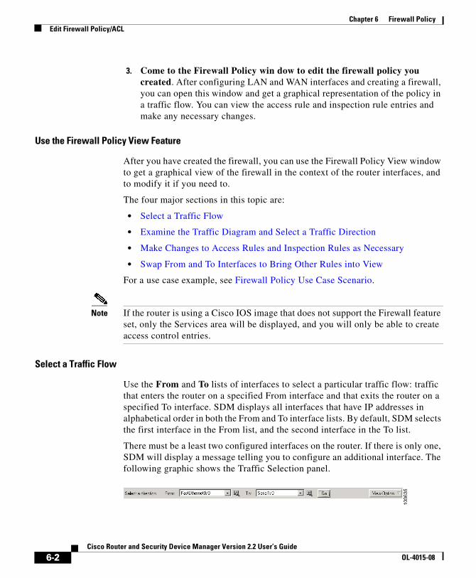
Chapter 6 Firewall PolicyEdit Firewall Policy/ACL
3. Come to the Firewall Policy win dow to edit the firewall policy you created. After configuring LAN and WAN interfaces and creating a firewall, you can open this window and get a graphical representation of the policy in a traffic flow. You can view the access rule and inspection rule entries and make any necessary changes.
Use the Firewall Policy View Feature
After you have created the firewall, you can use the Firewall Policy View window to get a graphical view of the firewall in the context of the router interfaces, and to modify it if you need to.
The four major sections in this topic are:
• Select a Traffic Flow
• Examine the Traffic Diagram and Select a Traffic Direction
• Make Changes to Access Rules and Inspection Rules as Necessary
• Swap From and To Interfaces to Bring Other Rules into View
For a use case example, see Firewall Policy Use Case Scenario.
Note If the router is using a Cisco IOS image that does not support the Firewall feature set, only the Services area will be displayed, and you will only be able to create access control entries.
Select a Traffic Flow
Use the From and To lists of interfaces to select a particular traffic flow: traffic that enters the router on a specified From interface and that exits the router on a specified To interface. SDM displays all interfaces that have IP addresses in alphabetical order in both the From and To interface lists. By default, SDM selects the first interface in the From list, and the second interface in the To list.
There must be a least two configured interfaces on the router. If there is only one, SDM will display a message telling you to configure an additional interface. The following graphic shows the Traffic Selection panel.
6-2Cisco Router and Security Device Manager Version 2.2 User’s Guide
OL-4015-08

Chapter 6 Firewall PolicyEdit Firewall Policy/ACL
From–Select the interface from which the traffic flow you are interested in originates. The firewall will protect the network connected to the From interface. The From list contains only interfaces with configured IP addresses.
To—Select the interface out of which the traffic will leave the router. . The To list contains only interfaces with configured IP addresses.
Example—To view the traffic flow from the network connected to the Ethernet 0 interface exiting the router on the Serial 0 interface exists, select From: Ethernet 0, and select To: Serial 0, and click Go.
Go button—Click Go to update the diagram with information about the interfaces you have selected. The diagram is not updated until you click Go. The Go button is disabled if you have not selecte a From interface or a To interface, or if the From and To interfaces are the same.
View Option—Selecting Swap From and To interface allows you to swap the interfaces that you originally selected without having to reselect them from the From list and the To list. You can use the swap option if you want to create a firewall protecting both the network connected to the From interface and the network connected to the To interface. You can select View all Access control lists in traffic flow when one access rule has been applied to the From interface and another access rule has been applied to the To interface for a traffic direction you have chosen. The entries of both access rules are displayed in another window.
Examine the Traffic Diagram and Select a Traffic Direction
The traffic diagram contains a diagram of the router, with a From interface and a To interface. When you select the From and To interfaces and click Go, this area is dynamically updated to show the selected interfaces and the types of rules applied, as well as the direction in which they have been applied.
The following illustration shows the traffic selection panel and the traffic diagram area displaying the access rules and inspection rules in the selected traffic flow.
Details button. Click to view details about the interface. Details such as IP address, encapsulation type, associated IPSec policy, and authentication type are provided.
6-3Cisco Router and Security Device Manager Version 2.2 User’s Guide
OL-4015-08
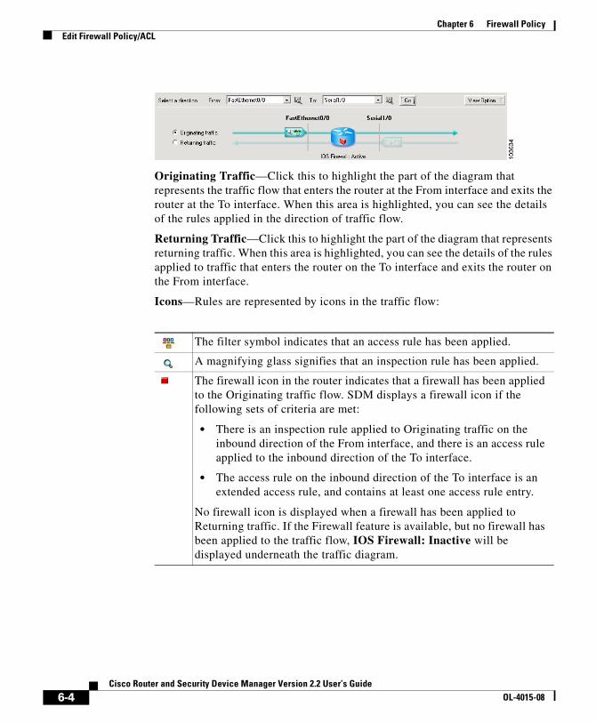
Chapter 6 Firewall PolicyEdit Firewall Policy/ACL
Originating Traffic—Click this to highlight the part of the diagram that represents the traffic flow that enters the router at the From interface and exits the router at the To interface. When this area is highlighted, you can see the details of the rules applied in the direction of traffic flow.
Returning Traffic—Click this to highlight the part of the diagram that represents returning traffic. When this area is highlighted, you can see the details of the rules applied to traffic that enters the router on the To interface and exits the router on the From interface.
Icons—Rules are represented by icons in the traffic flow:
The filter symbol indicates that an access rule has been applied.
A magnifying glass signifies that an inspection rule has been applied.
The firewall icon in the router indicates that a firewall has been applied to the Originating traffic flow. SDM displays a firewall icon if the following sets of criteria are met:
• There is an inspection rule applied to Originating traffic on the inbound direction of the From interface, and there is an access rule applied to the inbound direction of the To interface.
• The access rule on the inbound direction of the To interface is an extended access rule, and contains at least one access rule entry.
No firewall icon is displayed when a firewall has been applied to Returning traffic. If the Firewall feature is available, but no firewall has been applied to the traffic flow, IOS Firewall: Inactive will be displayed underneath the traffic diagram.
6-4Cisco Router and Security Device Manager Version 2.2 User’s Guide
OL-4015-08

Chapter 6 Firewall PolicyEdit Firewall Policy/ACL
Make Changes to Access Rules and Inspection Rules as Necessary
The policy panel shows the details of the rules applied to the selected traffic flow. The Policy panel is updated when the From and To interfaces are selected and when the Traffic Diagram is toggled between Originating Traffic focus and Returning Traffic focus.
ThePolicy panel is blank if an access rule that contains no entries has been associated with an interface. For example, if a rule name was associated with an interface using the CLI, but entries for the rule were not created, this panel would be blank. If the Policy Panel is blank, you can use the Add button to create entries for the rule.
Rules applied to Originating traffic are indicated by a right arrow. An icon on the From interface traffic line indicates the presence of a rule filtering traffic inbound to the router. An icon placed on the To interface traffic line indicates a rule filtering traffic outbound from the router. If you place the mouse over this icon, SDM will display the names of the rules that have been applied.
Rules applied to Returning traffic are indicated by a left arrow. An icon on the To interface traffic line indicates the presence of a rule filtering traffic inbound to the router. An icon on the From interface traffic line indicates the presence of a rule filtering traffic outbound from the router. The names of the rules applied are displayed when you place the cursor over this icon.
Although the icons are shown on a particular interface in the diagram, a firewall policy might contain access control entries that affect traffic that is not represented by the diagram. For example, an entry that contains the wildcard icon in the Destination column, indicating any network or host, might apply to traffic exiting interfaces other than the one represented by the currently selected To interface.
6-5Cisco Router and Security Device Manager Version 2.2 User’s Guide
OL-4015-08

Chapter 6 Firewall PolicyEdit Firewall Policy/ACL
Service Area header fields
Firewall Feature Availability—If the Cisco IOS image that the router is using supports the Firewall feature, this field contains the value Available.
Access Rule—The name or number of the access rule whose entries are being displayed.
Inspection Rule—The name of the inspection rule whose entries are being displayed.
Interface List—If the selected traffic flow (Originating or Returning) contains an access rule on both the From interface and the To interface, you can use this list to toggle between the two rules.
Service Area buttons
Add—Click to add an access rule entry. Specify whether you want to add the entry before or after the entry currently selected. Then, create the entry in the Add an Entry window. Remember that the order of entries is important. SDM displays
This icon appears when an access rule has been associated with an interface, but no access rule of that name or number has been created. SDM informs you that the policy has no effect unless there is at least one access rule entry.
Service area buttons are disabled if the rule is read-only. A rule is read-only when it contains syntax that SDM does not support.
6-6Cisco Router and Security Device Manager Version 2.2 User’s Guide
OL-4015-08

Chapter 6 Firewall PolicyEdit Firewall Policy/ACL
the Extended entry dialog when you add an entry from the Edit Firewall Policy/ACL window. If you want to add a standard rule entry, you can do so in the Rules window.
Edit—Click to edit a selected access rule entry. Although you can only add extended rule entries in the Edit Firewall Policy/ACL window, you are not prevented from editing a standard rule entry that has already been applied to a selected interface.
Cut—Click to remove a selected access rule entry. The entry is placed on the clipboard and can be pasted to another position in the list, or it can be pasted to another access rule. If you want to reorder an entry, you can cut the entry from one location, select an entry before or after the location that you want for the cut entry, and click Paste. The Paste context menu allows you to place the entry before or after the entry you selected.
Copy—Select a rule entry and click to put the rule entry on the clipboard.
Paste—Click to paste an entry on the clipboard to the selected rule. You will be prompted to specify whether you want to paste the entry before or after the currently selected entry. If SDM determines that an identical entry already exists in the access rule, it displays the Add an Extended Rule Entry window so that you can modify the entry. SDM does not allow duplicate entries in the same access rule.
If there is an existing standard rule that filters the returning traffic flow to which you are applying the firewall, SDM informs you that it will convert the standard access rule to an extended rule.
Examples—To apply a firewall that protects the network connected to the Ethernet 0 interface from traffic entering the Ethernet 1 interface, select From: Ethernet 0, and To: Ethernet 1. Then click Apply Firewall.
If the selected traffic flow does not have a firewall applied, you can apply a firewall by selecting Originating traffic and clicking the Apply Firewall button. By default, clicking Apply Firewall will associate an SDM-default inspection rule to the inbound direction of the From interface, andwill associate an access rule to the inbound direction of the To interface that denies traffic. If the Cisco IOS image that the router is using does not support the Firewall feature, this button is disabled.
6-7Cisco Router and Security Device Manager Version 2.2 User’s Guide
OL-4015-08

Chapter 6 Firewall PolicyEdit Firewall Policy/ACL
If you want to apply a firewall that protects the network connected to the Ethernet 1 interface from traffic entering the Ethernet 0 interface, you can do so in the Rules window.
Service Area Entry Fields
The following table describes the icons and other data in the Service Area entries.
Field Description Icons Meaning
Action Whether the traffic will be permitted or denied
Permit source traffic
Deny source traffic
Source/Destination
Network or host address, or any host or network.
The address of a network
The address of a host
Any network or host
Service Type of service filtered.
Examples: TCP, EIGRP, UDP, GRE. See IP Services.
Examples: Telnet, http, FTP. See TCP Services.
Examples: SNMP, bootpc, RIP. See UDP Services.
Internet Group Management Protocol (IGMP).
Examples: echo-reply, host-unreachable. See ICMP Message Types.
Log Whether or not denied traffic is logged.
Log denied traffic.
Option Options configured using the CLI
No icons.
Description Any description provided.
No icons
6-8Cisco Router and Security Device Manager Version 2.2 User’s Guide
OL-4015-08
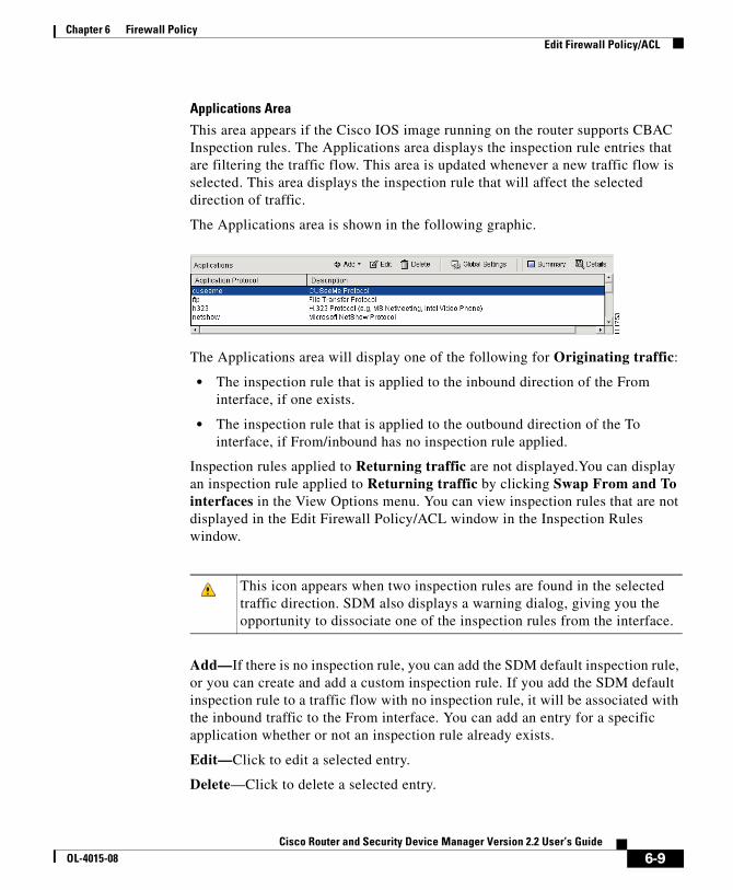
Chapter 6 Firewall PolicyEdit Firewall Policy/ACL
Applications Area
This area appears if the Cisco IOS image running on the router supports CBAC Inspection rules. The Applications area displays the inspection rule entries that are filtering the traffic flow. This area is updated whenever a new traffic flow is selected. This area displays the inspection rule that will affect the selected direction of traffic.
The Applications area is shown in the following graphic.
The Applications area will display one of the following for Originating traffic:
• The inspection rule that is applied to the inbound direction of the From interface, if one exists.
• The inspection rule that is applied to the outbound direction of the To interface, if From/inbound has no inspection rule applied.
Inspection rules applied to Returning traffic are not displayed.You can display an inspection rule applied to Returning traffic by clicking Swap From and To interfaces in the View Options menu. You can view inspection rules that are not displayed in the Edit Firewall Policy/ACL window in the Inspection Rules window.
Add—If there is no inspection rule, you can add the SDM default inspection rule, or you can create and add a custom inspection rule. If you add the SDM default inspection rule to a traffic flow with no inspection rule, it will be associated with the inbound traffic to the From interface. You can add an entry for a specific application whether or not an inspection rule already exists.
Edit—Click to edit a selected entry.
Delete—Click to delete a selected entry.
This icon appears when two inspection rules are found in the selected traffic direction. SDM also displays a warning dialog, giving you the opportunity to dissociate one of the inspection rules from the interface.
6-9Cisco Router and Security Device Manager Version 2.2 User’s Guide
OL-4015-08

Chapter 6 Firewall PolicyEdit Firewall Policy/ACL
Global Settings—Click to display a dialog box that enables you to set global timeouts and thresholds.
Summary—Click to display the application or protocol name and description for each entry.
Detail—Click to display the application or protocol name, description, alert status, audit trail status, and timeout settings for each entry.
Application Area entry fields
The following table describes the Application area entry fields.
Apply Changes Button
Click to deliver changes you have made in this window to the router. If you leave the Edit Edit Firewall Policy/ACL window without clicking Apply Changes, SDM displays a message indicating that you must either apply changes or discard them.
Discard Changes Button
Click to discard changes you have made in this window. This button does not let you remove changes that you have delivered to the router using the Apply Changes button.
Application Protocol Alert Audit Trail Timeout Description
The name of the application or protocol
Whether or not alert is enabled
Whether or not audit trail is enabled
How long the router should wait before blocking return traffic for this protocol or application
Short description
Example vdolive default-on
on
off
default-off
on
off
3600 (seconds) VDOLive protocol.
6-10Cisco Router and Security Device Manager Version 2.2 User’s Guide
OL-4015-08

Chapter 6 Firewall PolicyEdit Firewall Policy/ACL
Swap From and To Interfaces to Bring Other Rules into View
SDM only displays inspection rules for Originating traffic in the Application area. If you want to view an inspection rule that is applied to Returning traffic in the diagram, select Swap From and To interfaces in the View Options menu.
Add App-Name Application EntryUse this window to add an application entry that you want the Cisco IOS firewall to inspect.
Alert Action
One of the following:
• default-on—Leave as default. Default value is on.
• on—Enable alert.
• off—Disable alert.
Audit Action
One of the following:
• default-off—Leave as default. Default value is off.
• on—Enable audit trail.
• off—Disable audit trail.
Timeout
Specify how long the router should wait before blocking return traffic for this protocol or application. The field is prefilled with the default value for the protocol or application.
Add rpc Application EntryAdd a Remote Procedure Call (RPC) program number in this window, and specify Alert, Audit, Timeout, and Wait time settings.
6-11Cisco Router and Security Device Manager Version 2.2 User’s Guide
OL-4015-08
Chapter 6 Firewall PolicyEdit Firewall Policy/ACL
Alert Action
One of the following:
• default-on—Leave as default. Default value is on.
• on—Enable alert.
• off—Disable alert.
Audit Action
One of the following:
• default-off—Leave as default. Default value is off.
• on—Enable audit trail.
• off—Disable audit trail.
Timeout
Specify how long the router should wait before blocking return traffic for this protocol or application. The field is prefilled with the default value.
Program Number
Enter a single program number in this field.
Wait Time
You can optionally specify how many minutes to allow subsequent RPC connections from the same source to be made to the same destination address and port. The default wait time is zero minutes.
Add Fragment application entryIn this window, you can add a fragment entry to an inspection rule that you are configuring in the Edit Firewall Policy/ACL window, and you can specify Alert, Audit, and Timeout settings. A fragment entry sets the maximum number of unreassembled packets that the router should accept before dropping them.
6-12Cisco Router and Security Device Manager Version 2.2 User’s Guide
OL-4015-08

Chapter 6 Firewall PolicyEdit Firewall Policy/ACL
Alert Action
One of the following:
• default(on)—Leave as default. Default value is on.
• on—Enable alert.
• off—Disable alert.
Audit Action
One of the following:
• default(off)—Leave as default. Default value is off.
• on—Enable audit trail.
• off—Disable audit trail.
Timeout
Specify how long the router should wait before blocking return traffic for this protocol or application. The field is prefilled with the default value.
Range (optional)
Enter the maximum number of unreassembled packets the router should accept before dropping them. Enter a value between 50 and 10000.
Add or Edit http Application EntryUse this window to add an http application to the inspection rule.
Alert Action
One of the following:
• default-on—Leave as default. Default value is on.
• on—Enable alert.
• off—Disable alert.
6-13Cisco Router and Security Device Manager Version 2.2 User’s Guide
OL-4015-08

Chapter 6 Firewall PolicyEdit Firewall Policy/ACL
Audit Action
One of the following:
• default-off—Leave as default. Default value is off.
• on—Enable audit trail.
• off—Disable audit trail.
Timeout
Specify how long the router should wait before blocking return traffic for this protocol or application. The field is prefilled with the default value.
Hosts/network for Java applet download
The source hosts or networks whose applet traffic is to be inspected. Multiple hosts and networks can be specified.
Click Add to display the Java Applet Blocking window in which you can specify a host or network.
Click Delete to remove an entry from the list.
Java Applet BlockingUse this window to specify whether Java applets from a specified network or host should be permitted or denied.
Action
One of the following:
• Do Not Block (Permit)—Permit Java applets from this network or host.
• Block (Deny)—Deny Java applets from this network or host.
Host/Network
Specify the network or the host.
6-14Cisco Router and Security Device Manager Version 2.2 User’s Guide
OL-4015-08

Chapter 6 Firewall PolicyEdit Firewall Policy/ACL
Type
One of the following:
• A Network—If you select this, provide a network address in the IP address field. Note that the wildcard mask enables you to enter a network number that may specify multiple subnets.
• A Host Name or IP Address—If you select this, provide a host IP address or host name in the next field.
• Any IP address—If you select this, the action you specified is to apply to any host or network.
IP Address/Wildcard Mask
Enter a network address and then the wildcard mask to specify how much of the network address must match exactly.
For example, if you entered a network address of 10.25.29.0 and a wildcard mask of 0.0.0.255, any Java applet with a source address containing 10.25.29 would be filtered. If the wildcard mask were 0.0.255.255, any Java applet with a source address containing 10.25 would be filtered.
Host Name/IP
This field appears if you selected A Host Name or IP Address as Type. If you enter a host name, ensure that there is a DNS server on the network that can resolve the host name to an IP address.
SDM Warning: Inspection RuleThis window is displayed when SDM finds two inspection rules have been configured for a direction in a traffic flow. For example, you might have one inspection rule applied to the inbound traffic to the From interface, and another applied to the outbound traffic on the To interface. Two inspection rules may not harm the functioning of the router, but they may be unnecessary. SDM allows you to keep the inspection rules the way they are, to remove the inspection rule on the From interface, or to remove the rule on the To interface.
• Do not make any change—SDM will not remove either inspection rule.
• Keep inspection rule name on <interface-name> inbound, and dissociate inspection rule name on <interface-name> outbound—SDM will keep one inspection rule, and dissociate the rule from the other interface.
6-15Cisco Router and Security Device Manager Version 2.2 User’s Guide
OL-4015-08
Chapter 6 Firewall PolicyEdit Firewall Policy/ACL
• Keep inspection rule name on <interface-name> outbound and dissociate inspection rule name on <interface-name> inbound—SDM will keep one inspection rule, and dissociate the rule from the other interface.
Before you make a selection and click OK, you may want to click Cancel, and examine the two inspection rules to determine if you need to need to add entries to the inspection rule you want to retain. You can add entries by using the Add button in the Application area toolbar in the Edit Firewall Policy/ACL window.
SDM Warning: FirewallThis window appears when you click Apply Firewall in the Edit Firewall Policy/ACL window. It lists the interfaces to which it will apply a rule, and describes the rule that it will apply.
Example:
SDM will apply firewall configuration to the following interfaces:Inside (Trusted) Interface: FastEthernet 0/0* Apply inbound default SDM Inspection rule* Apply inbound ACL. Anti-spoofing, broadcast, local loopback, etc.).
Outside (Untrusted) Interface: Serial 1/0* Apply inbound access list to deny returning traffic.
Click OK to accept these changes, or click Cancel to stop the application of the firewall.
6-16Cisco Router and Security Device Manager Version 2.2 User’s Guide
OL-4015-08

Cisco Router and Security DeOL-4015-08
C H A P T E R 7
Application SecurityApplication Security allows you to create security policies to govern the use of network and web applications. You can apply the policies that you create to specific interfaces, clone an existing policy to leverage the settings for a new policy, and remove policies from the router.
Application Security WindowsThe controls in the Application Security windows allow you to associate policies with interfaces, make global settings, and add, delete and clone application security policies. The application security drawers enable you to quickly navigate to the application security area in which you need to make changes.
Policy Name List
Select the policy that you want to modify from this list. If there are no policies configured, this list is empty, and the Application Security window displays a message that indicates no policies are available on the router. To create a policy click the Action button, and choose Add.
Application Security Buttons
• Action button—Click to add a policy, delete the chosen policy, or clone the chosen policy. If no policies are configured on the router, Add is the only action available.
7-17vice Manager Version 2.2 User’s Guide

Chapter 7 Application SecurityApplication Security Windows
• Associate button—Click to display a dialog that allows you to associate the policy with an interface. The dialog allows to choose the interface, and to specify the traffic direction to which the policy is to apply.
• Global Settings button—Click to make settings to timeout and threshold values that apply to all policies. Click Global Settings for more information.
E-mail Drawer
Click this drawer to make changes to e-mail application security settings. Click E-mail for more information.
HTTP Drawer
Click this drawer to make changes to HTTP security settings. Click HTTP for more information.
Instant Messaging Drawer
Click this drawer to make changes to security settings for Yahoo Messenger, MSN Messenger, and other instant messaging applications. Click Instant Messaging for more information.
Point-to-Point Drawer
Click this drawer to make changes to security settings for KaZa A, eDonkey, and other point-to-point applications. Click Point-to-Point Applications for more information.
Applications/Protocols Drawer
Click this drawer to make changes to the security settings of other applications and protocols. Click Applications/Protocols for more information.
7-18Cisco Router and Security Device Manager Version 2.2 User’s Guide
OL-4015-08

Chapter 7 Application SecurityNo Application Security Policy
No Application Security PolicySDM displays this window when you have clicked the Application Security tab, but no Application Security policy has been configured on the router. You can create a policy from this window, and view the global settings that provide default values for the parameters that you can set when you create policies.
Policy Name
This list is empty when no policy has been configured for the router. Choosing Add from the Action context menu enables you to create a policy name and to begin to make settings for the policy.
Action
When no policy has been configured on the router, you can choose Add from the context menu to create a policy. Once a policy has been configured, the other actions, Edit and Delete, are available.
Associate
When no policy has been configured this button is disabled. Once a policy has been created, you can click this button to associate the policy with an interface. See Associate Policy with an Interface for more information.
Global Settings
Global settings provide the default timouts , thresholds, and other values for policy parameters. SDM provides defaults for each parameter, and you can change each value to define a new default that will apply unless overridden for a specific application or protocol. When you are creating a policy, you can accept the default value for a particular parameter, or choose another setting. Because the Application Security configuration windows do not display the default values you must click this button to view them in the Global Timeouts and Thresholds window. See Global Timeouts and Thresholds for more information.
7-19Cisco Router and Security Device Manager Version 2.2 User’s Guide
OL-4015-08

Chapter 7 Application SecurityE-mail
E-mailSpecify the e-mail applications that you want to inspect in this window. To learn about the buttons and drawers available in the Application Security tab, click Application Security Windows.
Edit Button
Click this button to edit the settings for the chosen application. Settings that you make override the global settings configured on the router.
Applications Column
The name of the e-mail application, for example bliff, esmtp, and smtp. To edit the settings for an application, check the box to the left of the application name, and click Edit.
Alerts, Audit, and Timeout Columns
These columns display values that have been explicitly set for an application. If a setting has not been changed for an application, the column is empty. For example, if auditing has been enabled for the bliff application, but no changes have been made to the alert or to the timeout settings, the value on is displayed in the Audit column, but the Alert and Timeout columns are blank.
Options Column
This column can contain fields if there are other settings that have been made for the chosen application.
MAX Data field
Specifies the maximum number of bytes (data) that can be transferred in a single Simple Mail Transport Protocol (SMTP) session. After the maximum value is exceeded, the firewall logs an alert message and closes the session. Default value: 20 MB.
Secure login checkbox
Causes a user at a non-secure location to use encryption for authentication.
7-20Cisco Router and Security Device Manager Version 2.2 User’s Guide
OL-4015-08

Chapter 7 Application SecurityHTTP
Reset
Resets the TCP connection if the client enters a non-protocol command before authentication is complete.
Router Traffic
Enables inspection of traffic destined to or originated from a router. Applicable only for H.323, TCP, and UDP protocols.
HTTPSpecify general settings for HTTP traffic inspection in this window. To learn about the buttons and drawers available in the Application Security tab, click Application Security Windows.
Click Permit, Block, and Alarm Controls to learn how to specify the action that the router is to take when it encounters traffic with the characteristics that you specify in this window.
For more detailed information about how the router can inspect HTTP traffic, refer to the document at the following link:
http://www.cisco.com/en/US/products/ps6350/products_configuration_guide_chapter09186a0080455acb.html
Detect non-compliant HTTP traffic Checkbox
Check this box if you want SDM to examine HTTP traffic for packets that do not comply with the HTTP protocol. Use the Permit, Block and Alarm controls to specify the action that you want SDM to take when this type of traffic is encountered.
Detect tunneling applications Checkbox
Check this box if you want SDM to examine HTTP traffic for packets that are generated by tunneling applications. Use the Permit, Block and Alarm controls to specify the action that you want SDM to take when this type of traffic is encountered.
7-21Cisco Router and Security Device Manager Version 2.2 User’s Guide
OL-4015-08
Chapter 7 Application SecurityHTTP
Set maximum URI length inspection Checkbox
Check this box if you want to define a maximum length for Universal Resource Indicators (URIs). Specify the maximum length in bytes, and then use the Permit, Block, and Alarm controls to specify the action that the router is to take when an URL that is longer than this value is encountered.
Enable HTTP inspection checkbox
Check this box if you want the router to inspect HTTP traffic. If you want to block traffic from Java applications, you can specify a Java blocking filter by clicking the ... button and either specifying an existing ACL, or creating a new ACL for Java inspection.
Enable HTTPS inspection checkbox
Check this box if you want the router to inspect HTTPS traffic.
Set time out value checkbox
Check this box if you want to set a time out for HTTP sessions, and enter the number of second in the Time-Out field. Sessions will be dropped that exceed this amount of time.
Enable audit trail
You can make CBAC audit trail settings for HTTP traffic that will override the setting in the Global Timeouts and Thresholds window. Default means that the current global setting will be used. On explicitly enables the CBAC audit trail for HTTP traffic and for HTTPS traffic if HTTPS inspection is enabled, and overrides the global audit trail setting. Off explicitly disables the CBAC audit trail for HTTP traffic and for HTTPS traffic if HTTPS inspection is enabled, and overrides the global audit trail setting
7-22Cisco Router and Security Device Manager Version 2.2 User’s Guide
OL-4015-08

Chapter 7 Application SecurityHTTP
Header OptionsYou can have the router permit or deny traffic based on HTTP header length and the request method contained in the header. Request methods are the commands sent to HTTP servers to fetch URLs, web pages, and perform other actions. To learn about the buttons and drawers available in the Application Security tab, click Application Security Windows.
Set maximum header length checkbox
Check this box if you want the router to permit or deny traffic based on HTTP header length, and specify the maximum Request and maximum Response header length. Use the Permit, Block, and Alarm controls to specify the action the router is to take when header length exceeds these values.
Configure Extension Request Method checkboxes
If you want the router to permit or deny HTTP traffic based on an extension request method, check the box next to that request method. Use the Permit, Block, and Alarm controls to specify the action the router is to take when it encounters traffic using that request method.
Configure RFC Request Method checkboxes
If you want the router to permit or deny HTTP traffic based on one of the HTTP request methods specified in RFC 2616, Hypertext Transfer Protocol—HTTP/1.1, check the box next to that request method. Use the Permit, Block, and Alarm controls to specify the action the router is to take when it encounters traffic using that request method.
Content OptionsYou can have the router examine the content of HTTP traffic and permit or block traffic, and generate alarms based on what things that you make the router check. To learn about the buttons and drawers available in the Application Security tab, click Application Security Windows.
7-23Cisco Router and Security Device Manager Version 2.2 User’s Guide
OL-4015-08

Chapter 7 Application SecurityHTTP
Click Permit, Block, and Alarm Controls to learn how to specify the action that the router is to take when it encounters traffic with the characteristics that you specify in this window.
Verify Content Type checkbox
Check this box if you want the router to verify the content of HTTP packets by matching the response with the request, by enabling an alarm for unknown content types, or by using both of these methods. Use the permit, block, and alarm controls to specify the action the router is to take when requests cannot be matched with responses, and when it encounters an unknown content type.
Set Content Length checkbox
Check this box to set a minimum and maximum length for the data in an HTTP packet, and enter the values in the fields provided. Use the permit, block, and alarm controls to specify the action the router is to take when the amount of data falls below the minimum length or when it exceeds the maximum length.
Configure Transfer Encoding Checkbox
Check this box to have the router verify how the data in the packet is encoded, and use the permit, block, and alarm controls to specify the action the router is to take when it encounters the transfer encodings that you choose.
Chunk checkbox
The Encoding format specified in RFC 2616, Hypertext Transfer Protocol—HTTP/1. The body of the message is transferred in a series of chunks; each chunk contains its own size indicator.
Compress checkbox
The encoding format produced by the UNIX "compress" utility.
Deflate checkbox
The "ZLIB" format defined in RFC 1950, ZLIB Compressed Data Format Specification version 3.3, combined with the "deflate" compression mechanism described in RFC 1951, DEFLATE Compressed Data Format Specification version 1.3.
7-24Cisco Router and Security Device Manager Version 2.2 User’s Guide
OL-4015-08

Chapter 7 Application SecurityInstant Messaging
gzip checkbox
The encoding format produced by the GNU zip (“gzip”) program.
Identity checkbox
Default encoding, which indicates that no encoding has been performed.
Instant MessagingUse this window to control the traffic for instant messaging applications such as Yahoo Messenger, and MSN Messenger. To learn about the buttons and drawers available in the Application Security tab, click Application Security Windows.
Click Permit, Block, and Alarm Controls to learn how to specify the action that the router is to take when it encounters traffic with the characteristics that you specify in this window.
The following example shows traffic blocked for Yahoo Messenger traffic, and alarms generated when traffic for that application arrives:
Yahoo Messenger Block Send Alarm (checked)
Point-to-Point ApplicationsThis page allows you to create policy settings for Peer-to-Peer applications such as Gnutella, BitTorrent, and eDonkey. To learn about the buttons and drawers available in the Application Security tab, click Application Security Windows.
Click Permit, Block, and Alarm Controls to learn how to specify the action that the router is to take when it encounters traffic with the characteristics that you specify in this window.
The following example shows traffic blocked for BitTorrent traffic, and alarms generated when traffic for that application arrives:
BitTorrent Block
7-25Cisco Router and Security Device Manager Version 2.2 User’s Guide
OL-4015-08
Chapter 7 Application SecurityApplications/Protocols
Applications/ProtocolsThis window allows you to create policy settings for applications and protocols that are not found in the other windows. To learn about the buttons and drawers available in the Application Security tab, click Application Security Windows.
Applications/Protocols Tree
The Applications/Protocols tree enables you to filter the list on the right according to the type of applications and protocols that you want to view. First choose the branch for the general type that you want to display. The frame on the right displays the available items for the type that you chose. If a plus (+) sign appears to the left of the branch, there are subcategories that you can use to refine the filter. Click on the + sign to expand the branch and then select the subcategory that you want to display. If the list on the right is empty, there are no applications or protocols available for that type. To choose an application, you can check the box next to it in the tree, or you can check the box next to it in the list.
Example: If you want to display all Cisco applications, click the Applications branch folder, and then click the Cisco folder. You will see applications like clp, cisco-net-mgmt, and cisco-sys.
Edit Button
Click this button to edit the settings for the chosen application. Settings that you make override the global settings configured on the router.
Applications Column
The name of the application or protocol, for example tcp, smtp, or ms-sna. To edit the settings for an item, check the box to the left of the item name, and click Edit.
Alerts, Audit, and Timeout Columns
These columns display values that have been explicitly set for an item. If a setting has not been changed for an item, the column is empty. For example, if auditing has been enabled for the ms-sna application, but no changes have been made to the alert or to the timeout settings, the value on is displayed in the Audit column, but the Alert and Timeout columns are blank.
7-26Cisco Router and Security Device Manager Version 2.2 User’s Guide
OL-4015-08
Chapter 7 Application SecurityGlobal Timeouts and Thresholds
Options Column
This column can contain fields if there are other settings that have been made for the chosen item.
MAX Data
Specifies the maximum number of bytes (data) that can be transferred in a single Simple Mail Transport Protocol (SMTP) session. After the maximum value is exceeded, the firewall logs an alert message and closes the session. Default value: 20 MB.
Secure login
Causes a user at a non-secure location to use encryption for authentication.
Reset
Resets the TCP connection if the client enters a non-protocol command before authentication is complete.
Router Traffic
Enables inspection of traffic destined to or originated from a router. Applicable only for H.323, TCP, and UDP protocols.
Global Timeouts and ThresholdsThis screen lets you set Context-Based Access Control (CBAC) global timeouts and thresholds. CBAC uses timeouts and thresholds to determine how long to manage state information for a session and to determine when to drop sessions that do not become fully established. These timeouts and thresholds apply to all sessions.
Global Timer values can be specified in seconds, minutes, or hours.
TCP Connection Timeout Value
The amount of time to wait for a TCP connection to be established. The default value is 30 seconds.
7-27Cisco Router and Security Device Manager Version 2.2 User’s Guide
OL-4015-08
Chapter 7 Application SecurityGlobal Timeouts and Thresholds
TCP FIN Wait Timeout Value
The amount of time that a TCP session will still be managed after the firewall detects a FIN exchange. The default value is 4 seconds.
TCP IdleTimeout Talue
The amount of time that a TCP session will still be managed after no activity has been detected. The default value is 3600 seconds.
UDP Idle Timeout Value
The amount of time that a User Datagram Protocol (UDP) session will still be managed after no activity has been detected. The default value is 30 seconds.
DNS Timeout Value
The amount of time that a Domain Name System (DNS) name lookup session will be managed after no activity has been detected. The default value is 5 seconds
SYN Flooding DoS Attack Thresholds
An unusually high number of half-open sessions may indicate that a Denial of Service (DoS) attack is under way. DoS attack thresholds allow the router to start deleting half-open sessions after the total number of them has reached a maximum threshold. By defining thresholds, you can specify when the router should start deleting half-open sessions and when it can stop deleting them.
One-minute session thresholds. These fields let you specify the threshold values for new connection attempts.
Low Stop deleting new connections after the number of new connections drops below this value. The default value is 400 sessions.
High Start deleting new connections when the number of new connections exceeds this value. The default value is 500 sessions
7-28Cisco Router and Security Device Manager Version 2.2 User’s Guide
OL-4015-08

Chapter 7 Application SecurityGlobal Timeouts and Thresholds
TCP Maximum Incomplete Sessions per Host:
The router starts deleting half-open sessions for the same host when the total number for that host exceeds this number. The default number of sessions is 50. If you check the Blocking Time field and enter a value, the router will continue to block new connections to that host for the number of minutes that you specify.
Enable audit globally
Check this box if you want to turn on CBAC audit trail messages for all types of traffic.
Enable alert globally
Check this box if you want to turn on CBAC alert messages for all types of traffic.
Associate Policy with an InterfaceIn this window, select the interface to which you want to apply the selected policy. Also specify whether the policy is to apply to incoming traffic, to outgoing traffic, or to traffic in both directions.
For example, if the router had FastEthernet 0/0 and FastEthernet 0/1 interfaces, and you wanted to apply the policy to the FastEthernet 0/1 interface, on traffic flowing in both directions, you would check the box next to FastEthernet 0/1, and check the boxes in both the Incoming column and the Outgoing column. To have only incoming traffic inspected, you would only check the box in the Incoming column.
Maximum incomplete session thresholds. These fields let you specify the threshold values for the total number of existing half-open sessions.
Low Stop deleting new connections after the number of new connections drops below this value. The default value is 400 sessions
High Start deleting new connections when the number of new connections exceeds this value. The default value is 500 sessions
7-29Cisco Router and Security Device Manager Version 2.2 User’s Guide
OL-4015-08

Chapter 7 Application SecurityGlobal Timeouts and Thresholds
Edit Inspection RuleUse this window to specify custom inspection rule settings for an application. Settings made here and applied to the router’s configuration override the global settings.
Click the Global Settings button in the Application Security window to display the global settings for the parameters that you can set in this window. See Global Timeouts and Thresholds for more information.
Alert Field
Choose one of the following values:
• default—Use the global setting for alerts.
• on—Generate an alert when traffic of this type is encountered.
• off—Do not generate an alert when traffic of this type is encountered.
Audit Field
Choose one of the following values:
• default—Use the global setting for audit trails.
• on—Generate an audit trail when traffic of this type is encountered.
• off—Do not generate an audit trail when traffic of this type is encountered.
Timeout Field
Enter the number of seconds that a session for this application should be managed after no activity has been detected. The timeout value that you enter sets the TCP Idle Timeout value if this is a TCP application, or the UDP timeout value if this is a UDP application.
Other Options
Certain applications can have additional options set. Depending on the application, you may see the options described next.
7-30Cisco Router and Security Device Manager Version 2.2 User’s Guide
OL-4015-08

Chapter 7 Application SecurityGlobal Timeouts and Thresholds
MAX Data field
Specifies the maximum number of bytes (data) that can be transferred in a single Simple Mail Transport Protocol (SMTP) session. After the maximum value is exceeded, the firewall logs an alert message and closes the session. Default value: 20 MB.
Secure Login Checkbox
Causes a user at a non-secure location to use encryption for authentication.
Reset Checkbox
Resets the TCP connection if the client enters a non-protocol command before authentication is complete.
Router Traffic Checkbox
Enables inspection of traffic destined to or originated from a router. Applicable only for H.323, TCP, and UDP protocols.
Permit, Block, and Alarm ControlsUse the Permit, Block and Alarm controls to specify what the router is to do when it encounters traffic with the characteristics that you specify. To make a policy setting for an option with these controls, check the box next to it. Then, in the Action column, choose Permit to allow traffic related to that option, or choose Block to deny traffic. If you want an alarm to be sent to the log when this type of traffic is encountered, check Send Alarm. The Send Alarm control is not used in all windows.
7-31Cisco Router and Security Device Manager Version 2.2 User’s Guide
OL-4015-08

Chapter 7 Application SecurityGlobal Timeouts and Thresholds
7-32Cisco Router and Security Device Manager Version 2.2 User’s Guide
OL-4015-08

Cisco Router and Security DeOL-4015-08
C H A P T E R 8
Site-to-Site VPNThe help topics in this section describe the Site-to-Site configuration screens.
Create Site to Site VPNA Virtual Private Network (VPN) lets you protect traffic that travels over lines that your organization may not own or control. VPNs can encrypt traffic sent over these lines and authenticate peers before any traffic is sent.
You can let Cisco Router and Security Device Manager (SDM) guide you through a simple VPN configuration by clicking the VPN icon. When you use the Wizard in the Create Site-to-Site VPN tab, SDM provides default values for some configuration parameters in order to simplify the configuration process.
If you want to learn more about VPN technology, there is background information at the link More About VPN.
Create a Site-to-Site VPN
This option allows you to create a VPN network connecting two routers.
Create a Secure GRE Tunnel (GRE-over-IPSec)
This option allows you to configure a generic routing encapsulation protocol (GRE) tunnel between your router and a peer system.
8-33vice Manager Version 2.2 User’s Guide

Chapter 8 Site-to-Site VPNCreate Site to Site VPN
What Do You Want to Do?
If you want to: Do this:
Configure the router as part of a VPN network connecting two routers.
When you configure a VPN network between two routers, you can control how the remote router is authenticated, how traffic is encrypted, and what traffic is encrypted.
Select Create a site-to-site VPN . Then click Launch the selected task.
Configure a GRE tunnel between your router and another router.
You may want to configure a GRE tunnel if you need to connect networks that use different LAN protocols, or if you need to send routing protocols over the connection to the remote system.
Select Create a Secure GRE tunnel (GRE-over-IPSec). Then click Launch the selected task.
8-34Cisco Router and Security Device Manager Version 2.2 User’s Guide
OL-4015-08

Chapter 8 Site-to-Site VPNCreate Site to Site VPN
Find out how to perform other VPN-related tasks that this wizard does not guide you through.
Select a topic from the following list:
• How Do I View the IOS Commands I Am Sending to the Router?
• How Do I Create a VPN to More Than One Site?
• After Configuring a VPN, How Do I Configure the VPN on the Peer Router?
• How Do I Edit an Existing VPN Tunnel?
• How Do I Confirm That My VPN Is Working?
• How Do I Confirm That My VPN Is Working?
• How Do I Configure a Backup Peer for My VPN?
• How Do I Accommodate Multiple Devices with Different Levels of VPN Support?
• How Do I Configure a VPN on an Unsupported Interface?
• How Do I Configure a VPN After I Have Configured a Firewall?
• How Do I Configure NAT Passthrough for a VPN?
• How Do I Configure a DMVPN Manually?
If you want to: Do this:
8-35Cisco Router and Security Device Manager Version 2.2 User’s Guide
OL-4015-08
Chapter 8 Site-to-Site VPNCreate Site to Site VPN
Site-to-Site VPN WizardYou can have SDM use default settings for most of the configuration values, or you can let SDM guide you in configuring a VPN.
Configure an Easy VPN concentrator.
Configuration instructions for Easy VPN servers and concentrators are available on www.cisco.com.
The following link provides guidelines to use when configuring a Cisco VPN 3000 series concentrator to operate with an Easy VPN Remote Phase II client, and other information which you might find useful:
http://www.cisco.com/en/US/products/sw/iosswrel/ps5012/products_feature_guide09186a00800a8565.html
The following link connects you to Cisco VPN 3000 series documentation:
http://www.cisco.com/en/US/products/hw/vpndevc/ps2284/products_getting_started_guide_book09186a00800bbe74.html
If you want to: Do this:
8-36Cisco Router and Security Device Manager Version 2.2 User’s Guide
OL-4015-08

Chapter 8 Site-to-Site VPNCreate Site to Site VPN
What do you want to do?
View Defaults This window displays the default Internet Key Exchange (IKE) policy, transform set, and IPSec rule that SDM will use to configure a Quick Setup site-to-site VPN. If you need a different configuration than this window shows, check Step-by-Step wizard so that you can define configuration values.
If you want to: Do this:
Quickly configure a site-to-site VPN using SDM-provided defaults.
Check Quick setup, and then click Next.
SDM will automatically provide a default IKE policy to govern authentication, a default transform set to control the encryption of data and a default IPSec rule that will encrypt all traffic between the router and the remote device.
Quick setup is best used when both the local router and the remote system are Cisco routers using SDM.
Quick setup will configure 3DES encryption if it is supported by the IOS image. Otherwise, it will configure DES encryption. If you need AES or SEAL encryption, click Step-by-step wizard.
View the default IKE policy, transform set, and IPSec rule that will be used to configure a One-step VPN.
Click View Defaults.
Configure a site-to-site VPN using parameters that you specify.
Check Step-by-Step wizard, and then click Next.
You can create a custom configuration for the VPN, and use any of the SDM defaults that you need.
Step-by-step wizard allows you to specify stronger encryption than the Quick setup wizard allows.
8-37Cisco Router and Security Device Manager Version 2.2 User’s Guide
OL-4015-08
Chapter 8 Site-to-Site VPNCreate Site to Site VPN
VPN Connection InformationUse this window to identify the IP address or host name of the remote site that will terminate the VPN tunnel that you are configuring, to specify the router interface to use, and to enter the pre-shared key that both routers will use to authenticate each other.
Select the interface for This VPN Connection
Select the interface on this router that connects to the remote site.The router you are configuring is represented as the Local router in the Use Case Scenario diagram.
Peer Identity
Enter the IP address of the remote IP Security (IPSec) peer that will terminate the VPN tunnel you are configuring. The remote IPSec peer might be another router, a VPN concentrator, or any other gateway device that supports IPSec.
Peer(s) with dynamic IP addresses
Select this option if the peers the router connects to use a dynamically-assigned IP addresses.
Peer with static IP address
Select this option if the peer the router connects to uses a fixed IP address.
Enter the IP Address of the remote peer
(Enabled when Peer with static IP address is selected). Enter the IP address of the remote peer.
Authentication
Click this button if the VPN peers use a pre-shared key to authenticate connections from each other. This key must be the same on each side of the VPN connection.
8-38Cisco Router and Security Device Manager Version 2.2 User’s Guide
OL-4015-08

Chapter 8 Site-to-Site VPNCreate Site to Site VPN
Enter the pre-shared key, and then reenter it for confirmation. Exchange the pre-shared key with the administrator of the remote site through some secure and convenient method, such as an encrypted e-mail message. Question marks (?) and spaces must not be used in the pre-shared key. The pre-shared key can contain a maximum of 128 characters.
Note • The characters you enter for the pre-shared key are not displayed in the field as you enter them. You may find it helpful to write down the key before you enter it so that you can communicate it to the administrator of the remote system.
• Pre-shared keys must be exchanged between each pair of IPSec peers that need to establish secure tunnels. This authentication method is appropriate for a stable network with a limited number of IPSec peers. It may cause scalability problems in a network with a large or increasing number of IPSec peers.
Digital Certificate
Click this button if the VPN peers will use digital certificates for authentication.
Note The router must have a digital certificate issued by a Certificate Authority to authenticate itself. If you have not configured a digital certificate for the router, go to VPN components, and use the Digital Certificate wizard to enroll for a digital certificate.
Traffic to Encrypt
If you are configuring a Quick Setup site-to-site VPN connection, you need to specify the source and destination subnets in this window.
Source
Choose the interface on the router that will be the source of the traffic on this VPN connection. All traffic coming through this interface whose destination IP address is in the subnet specified in the Destination area will be encrypted.
8-39Cisco Router and Security Device Manager Version 2.2 User’s Guide
OL-4015-08
Chapter 8 Site-to-Site VPNCreate Site to Site VPN
Details
Click this button to obtain details about the interface you selected. The details window shows any access rules, IPSec policies, Network Address Translation (NAT) rules, or Inspection rules associated with the interface. To examine any of these rules in more detail, go to Additional Tasks/ACL Editor, and examine them in the Rules windows.
Destination
IP address and Subnet Mask. Enter the IP address and subnet mask of the destination for this traffic. For more information about how to enter values in these fields, see IP Addresses and Subnet Masks.
The destination is depicted as the Remote router in the Use Case Scenario diagram in the main VPN wizard window.
IKE ProposalsThis window lists all the Internet Key Exchange (IKE) policies that have been configured on the router. If no user-defined policies have been configured, the windows lists the SDM default IKE policy. IKE policies govern the way that devices in a VPN authenticate themselves.
The local router will use the IKE policies listed in this window to negotiate authentication with the remote router.
The local router and the peer device must both use the same policy. The router that initiates the VPN connection offers the policy with the lowest priority number first. If the remote system rejects that policy, the local router offers the policy with the next lowest number, and continues in this fashion until the remote system accepts. You must coordinate closely with the administrator of the peer system so that you can configure identical policies on both routers.
For Easy VPN connections, IKE policies are only configured on the Easy VPN server. The Easy VPN client sends proposals, and the server responds according to its configured IKE policies.
Priority
This is the order in which the policy will be offered during negotiation.
8-40Cisco Router and Security Device Manager Version 2.2 User’s Guide
OL-4015-08

Chapter 8 Site-to-Site VPNCreate Site to Site VPN
Encryption
SDM supports a variety of encryption types, listed in order of security. The more secure an encryption type is, the more processing time it requires.
Note • Not all routers support all encryption types. Unsupported types will not appear in the screen.
• Not all IOS images support all the encryption types that SDM supports. Types unsupported by the IOS image will not appear in the screen.
• If hardware encryption is turned on, only those encryption types supported by hardware encryption will appear in the screen.
SDM supports the following types of encryption:
• DES—Data Encryption Standard. This form of encryption supports 56-bit encryption.
• 3DES—Triple DES. This is a stronger form of encryption than DES, supporting 168-bit encryption.
• AES-128—Advanced Encryption Standard (AES) encryption with a 128-bit key. AES provides greater security than DES and is computationally more efficient than 3DES.
• AES-192—AES encryption with a 192-bit key.
• AES-256—AES encryption with a 256-bit key.
8-41Cisco Router and Security Device Manager Version 2.2 User’s Guide
OL-4015-08
Chapter 8 Site-to-Site VPNCreate Site to Site VPN
Hash
The authentication algorithm to be used for the negotiation. SDM supports the following algorithms:
• SHA_1—Secure Hash Algorithm. A hash algorithm used to authenticate packet data.
• MD5—Message Digest 5. A hash algorithm used to authenticate packet data.
D-H Group
The Diffie-Hellman Group—Diffie-Hellman is a public-key cryptography protocol that allows two routers to establish a shared secret over an unsecure communications channel. SDM supports the following groups:
• group1—D-H Group 1. 768-bit D-H Group.
• group2—D-H Group 2. 1024-bit D-H Group. This group provides more security than group 1, but requires more processing time.
• group5—D-H Group 5.1536-bit D-H Group. This group provides more security than group 2, but requires more processing time.
Note Diffie-Hellman group5 is not supported on all routers.
Authentication
The authentication method to be used. The following value is supported:
• PRE_SHARE—Authentication will be performed using pre-shared keys.
• RSA_SIG—Authentication will be performed using digital certificates.
Type
Either SDM Default or User Defined. If no User Defined policies have been created on the router, this window will show the default IKE policy.
8-42Cisco Router and Security Device Manager Version 2.2 User’s Guide
OL-4015-08
Chapter 8 Site-to-Site VPNCreate Site to Site VPN
To add or edit an IKE policy:
If you want to add an IKE policy that is not included in this list, click Add and create the policy in the window displayed. Edit an existing policy by selecting it and clicking Edit. SDM Default policies are read only, and cannot be edited.
To accept the policy list:
To accept the IKE policy list and continue, click Next.
Transform SetThis window lists the SDM-default transform sets and the additional transform sets that have been configured on this router. These transform sets will be available for use by the VPN or DMVPN. A transform set represents a certain combination of security protocols and algorithms. During the IPSec security association negotiation, the peers agree to use a particular transform set for protecting a particular data flow. A transform describes a particular security protocol with its corresponding algorithms.
You can select only one transform set in this window, but you can associate additional transform sets to the VPN or DMVPN connection using the VPN or DMVPN Edit tabs.
Select Transform Set
Select the transform set that you want to use from this list.
Details of the Selected Transform Set
This area supplies details about the selected transform set. Not all types of encryption, authentication, and compression have to be configured; therefore, some columns may not contain values.
To learn the possible values each column may contain, click Add or Edit Transform Set.
Name
The name given to this transform set.
8-43Cisco Router and Security Device Manager Version 2.2 User’s Guide
OL-4015-08
Chapter 8 Site-to-Site VPNCreate Site to Site VPN
ESP Encryption
The type of Encapsulating Security Protocol (ESP) encryption used. If ESP encryption is not configured for this transform set, this column will be empty.
ESP Authentication
The type of ESP authentication used. If ESP authentication is not configured for this transform set, this column will be empty.
AH Authentication
The type of Authentication Header (AH) authentication used. If AH authentication is not configured for this transform set, this column will be empty.
IP Compression
If IP compression is configured for this transform set, this field contains the value COMP-LZS.
Note IP compression is not supported on all routers.
Mode
This column contains one of the following:
• Transport—Encrypt data only. Transport mode is used when both endpoints support IPsec. Transport mode places the authentication header or encapsulated security payload after the original IP header; thus, only the IP payload is encrypted. This method allows users to apply network services such as quality-of-service (QoS) controls to encrypted packets.
• Tunnel—Encrypt data and IP header. Tunnel mode provides stronger protection than transport mode. Because the entire IP packet is encapsulated within AH or ESP, a new IP header is attached, and the entire datagram can be encrypted. Tunnel mode allows network devices such as routers to act as an IPsec proxy for multiple VPN users.
Type
Either User Defined, or SDM Default.
8-44Cisco Router and Security Device Manager Version 2.2 User’s Guide
OL-4015-08
Chapter 8 Site-to-Site VPNCreate Site to Site VPN
What Do You Want to Do?
Traffic to ProtectThis window lets you define the traffic that this VPN protects. The VPN can protect traffic between specified subnets, or protect the traffic specified in an IPSec rule that you select.
Protect All Traffic Between the Following Subnets
Use this option to specify a single source subnet (a subnet on the LAN) whose outgoing traffic you want to encrypt, and one destination subnet supported by the peer that you specified in the VPN Connection window.
All traffic flowing between other source and destination pairs will be sent unencrypted.
Source
Enter the address of the subnet whose outgoing traffic you want to protect, and specify the subnet mask. For more information, refer to Available Interface Configurations.
If you want to: Do this:
Select a transform set for the VPN to use.
Select a transform set, and click Next.
Add a transform set to the router’s configuration.
Click Add, and create the transform set in the Add Transform Set window. Then click Next to continue VPN configuration.
Edit an existing transform set. Select a transform set, and click Edit. Then, edit the transform set in the Edit Transform Set window. After editing the transform set, click Next to continue VPN configuration. SDM Default transform sets are read only and cannot be edited.
Associate additional transform sets with this VPN.
Select one transform set in this window, and complete the VPN wizard. Then, associate other transform sets to the VPN in the Edit tab.
8-45Cisco Router and Security Device Manager Version 2.2 User’s Guide
OL-4015-08
Chapter 8 Site-to-Site VPNCreate Site to Site VPN
All traffic from this source subnet that has a destination IP address on the destination subnet will be protected.
Destination
Enter the address of the destination subnet, and specify the mask for that subnet. You can select a subnet mask from the list, or type in a custom mask. The subnet number and mask must be entered in dotted decimal format, as shown in the previous examples.
All traffic going to the hosts in this subnet will be protected.
Create/Select an access-list for IPSec traffic
Use this option if you need to specify multiple sources and destinations, and/or specific types of traffic to encrypt. An IPSec rule can consist of multiple entries, each specifying different traffic types and different sources and destinations.
Click the button next to the field, and specify an existing IPSec rule that defines the traffic you want to encrypt, or create an IPSec rule to use for this VPN. If you know the number of the IPSec rule, enter it in the box to the right. If you do not know the number of the rule, click the ... button and browse for the rule. When you select the rule, the number will appear in the box.
Note Because they can specify traffic type, and both source and destination, IPSec rules are extended rules. If you enter the number or name of a standard rule, a Warning message is displayed indicating that you have entered the name or number of a standard rule.
Any packets that do not match the criteria in the IPSec rule are sent with no encryption.
Summary of the ConfigurationThis window shows you the VPN or DMVPN configuration that you created. You can review the configuration in this window and use the back button to make changes if you want.
8-46Cisco Router and Security Device Manager Version 2.2 User’s Guide
OL-4015-08
Chapter 8 Site-to-Site VPNCreate Site to Site VPN
Spoke Configuration
If you have configured a DMVPN hub, you can have SDM generate a procedure that will assist you or other administrators in configuring DMVPN spokes. The procedure explains which options to select in the wizard, and what information to enter in spoke configuration windows. You can save this information to a text file that you or another administrator can use.
Test the connectivity after configuring
Click to test the VPN connection you have just configured.The results of the test will be shown in another window.
To save this configuration to the router’s running configuration and leave this wizard:
Click Finish. SDM saves the configuration changes to the router’s running configuration. The changes will take effect immediately, but will be lost if the router is turned off.
If you checked Preview commands before delivering to router in the SDM Preferences window, the Deliver window will appear . In this window, you can view the CLI commands you that are delivering to the router.
Spoke Configuration
This window contains information that you can use to give a spoke router a configuration that will be compatible with the DMVPN hub that you configured. It lists the windows you need to complete, giving you data that you need to enter in the window so that the spoke will be able to communicate with the hub.
It provides the following data that you need to input into the spoke configuration:
• The hub’s public IP address. This is the IP address of the hub interface that supports the mGRE tunnel.
• The IP address of the hub’s mGRE tunnel.
• The subnet mask that all tunnel interfaces in the DMVPN must use.
• The advanced tunnel configuration information.
• The routing protocol to use, and any information associated with the protocol, such as Autonomous System number (for EIGRP), and OSPF Process ID.
8-47Cisco Router and Security Device Manager Version 2.2 User’s Guide
OL-4015-08

Chapter 8 Site-to-Site VPNCreate Site to Site VPN
• The hash, encryption, DH group, and Authentication Type of the IKE policies that the hub uses, so that compatible IKE policies can be configured on the spoke.
• The ESP and Mode information of the transform sets that the hub uses. If similar transform sets have not been configured on the spoke, they can be configured using this information.
Secure GRE Tunnel (GRE-over-IPSec)Generic routing encapsulation (GRE) is a tunneling protocol developed by Cisco that can encapsulate a wide variety of protocol packet types inside IP tunnels, creating a virtual point-to-point link to Cisco routers at remote points over an IP internetwork. By connecting multiprotocol subnetworks in a single-protocol backbone environment, IP tunneling using GRE allows network expansion across a single-protocol backbone environment.
This wizard enables you to create a GRE tunnel with IPSec encryption. When you create a GRE tunnel configuration, you also create an IPSec rule that describes the endpoints of the tunnel.
GRE Tunnel InformationGeneral GRE tunnel information is provided in this screen.
Tunnel Source
Select the interface name or the IP address of the interface that the tunnel will use. The IP address of the interface must be reachable from the other end of the tunnel; therefore it must a a public, routable IP address. An error will be generated if you enter an IP address that is not associated with any configured interface.
Note SDM lists interfaces with static IP addresses and interfaces configured as unnumbered in the Interface list. Loopback interfaces are not included in the list.
8-48Cisco Router and Security Device Manager Version 2.2 User’s Guide
OL-4015-08
Chapter 8 Site-to-Site VPNCreate Site to Site VPN
Details
Click to obtain details about the interface that you selected. The details window shows any access rules, IPSec policies, NAT rules, or Inspection rules associated with the interface. If a NAT rule has been applied to this interface that causes the address to be unroutable, the tunnel will not operate properly. To examine any of these rules in more detail, go to Additional Tasks/ACL Editor and examine the in the Rules window.
Tunnel Destination
Enter the IP address of the interface on the remote router at the other end of the tunnel. This is the source interface from the point of view of the other end of the tunnel.
Make sure that this address is reachable by using the ping command. The ping command is available from the Tools menu. If the destination address cannot be reached, the tunnel will not be created properly.
IP Address of the GRE tunnel
Enter the IP address of the tunnel. The IP addresses of both ends of the tunnel must be in the same subnet. The tunnel is given a separate IP address so that it can be a private address, if necessary.
IP Address
Enter the IP address of the tunnel in dotted decimal format. For more information, see IP Addresses and Subnet Masks.
Subnet Mask
Enter the subnet mask for the tunnel address in dotted decimal format.
VPN Authentication InformationVPN peers use a pre-shared key to authenticate connections from each other. This key must be the same on each side of the VPN connection.
8-49Cisco Router and Security Device Manager Version 2.2 User’s Guide
OL-4015-08

Chapter 8 Site-to-Site VPNCreate Site to Site VPN
Pre-Shared Key
Click this button if the VPN peers use a pre-shared key for authentication and then enter the pre-shared key, and then reenter it for confirmation. Exchange the pre-shared key with the administrator of the remote site through some secure and convenient method, such as an encrypted e-mail message. Question marks (?) and spaces must not be used in the pre-shared key.
Note • The characters that you enter for the pre-shared key are not displayed in the field as you enter them. You may find it helpful to write down the key before you enter it so that you can communicate it to the administrator of the remote system.
• Pre-shared keys must be exchanged between each pair of IPSec peers that need to establish secure tunnels. This authentication method is appropriate for a stable network with a limited number of IPSec peers. It may cause scalability problems in a network with a large or increasing number of IPSec peers.
Digital Certificate
Click this button if the VPN peers will use digital certificates for authentication.
The router must have a digital certificate issued by a Certificate Authority to authenticate itself. If you have not configured a digital certificate for the router, go to VPN components, and use the Digital Certificate wizard to enroll for a digital certificate.
Note If you are authenticating using digital certificates, the VPN tunnel might not be created if the CA server contacted during IKE negotiation is not configured to respond to Certificate Revocation List (CRL) requests. To correct this problem, go to the Digital Certificates page, select the configured trustpoint, and select None for Revocation.
8-50Cisco Router and Security Device Manager Version 2.2 User’s Guide
OL-4015-08

Chapter 8 Site-to-Site VPNCreate Site to Site VPN
Backup GRE Tunnel InformationYou can configure a backup GRE-over-IPSec tunnel that the router can use when the primary tunnel fails. This tunnel will use the same interface that you configured for the primary tunnel, but it must be configured with the backup VPN router as the peer. If routing is configured for the primary GRE-over-IPSec tunnel, the keepalive packets that the routing protocol sends are used to verify that the tunnel is still active. If the router stops receiving keepalive packets on the primary tunnel, then traffic is sent through the backup tunnel.
Create a backup secure GRE tunnel for resilience
Check this box if you want to create a backup tunnel.
IP address of the backup GRE tunnel’s destination
Enter the IP address of the interface on the remote router at the other end of the tunnel. (This is the source interface from the point of view of the other end of the tunnel.)
Make sure that this address is reachable by using the ping command. The ping command is available from the Tools menu. If the destination address specified in the Ping dialog cannot be reached, the tunnel will not be created properly.
Tunnel IP address
Enter the IP address of the tunnel. The IP addresses of both ends of the tunnel must be in the same subnet. The tunnel is given a separate IP address so that it can be a private address, if necessary.
IP Address
Enter the IP address of the tunnel in dotted decimal format. For more information, see IP Addresses and Subnet Masks.
Subnet Mask
Enter the subnet mask for the tunnel address in dotted decimal format.
8-51Cisco Router and Security Device Manager Version 2.2 User’s Guide
OL-4015-08

Chapter 8 Site-to-Site VPNCreate Site to Site VPN
Routing InformationThis window enables you to configure routing for the tunneled traffic. Information that you add in this window appears in the Routing window. Changes that you make in the Routing window may affect routing of VPN traffic. Configuring routing enables you to specify the networks that will participate in the GRE-over-IPSec VPN. Additionally, if you configure a backup GRE-over-IPSec tunnel, the keepalive packets sent by routing protocols allow the router to determine whether the primary tunnel has failed.
Select a dynamic routing protocol if this router is being used in a large VPN deployment with a large number of networks in the GRE over IPSec VPN. Select static routing if a small number of networks will participate in the VPN.
EIGRP
Check this box to use the Enhanced Interior Gateway Routing Protocol (EIGRP) protocol to route traffic. Then click Next to specify which networks will participate in the GRE-over-IPSec VPN in the Routing Information window.
OSPF
Check this box to use the Open Shortest Path First protocol (OSPF) to route traffic. Then click Next to specify which networks will participate in the GRE-over-IPSec VPN in the Routing Information window.
RIP
Check this box to use the Routing Information Protocol(RIP) to route traffic. Then click Next to specify which networks will participate in the GRE-over-IPSec VPN in the Routing Information window.
Note This option is not available when you configure a backup GRE-over-IPSec tunnel.
8-52Cisco Router and Security Device Manager Version 2.2 User’s Guide
OL-4015-08

Chapter 8 Site-to-Site VPNCreate Site to Site VPN
Static Routing
Static routing can be used in smaller VPN deployments in which only a few private networks participate in the GRE-over-IPSec VPN. You can configure a static route for each remote network so that traffic destined for the remote networks will pass through the appropriate tunnels.
Static Routing InformationYou can configure a static route for each remote network so that traffic destined for the remote networks will pass through the appropriate tunnels. Configure the first static route in the Static Routing Information window. If you need to configure additional static routes, you can do so in the Routing window.
Check this box if you want to specify a static route for the tunnel, and select one of the following:
• Tunnel all traffic—All traffic will be routed through the tunnel interface and encrypted. SDM creates a default static route entry with the tunnel interface as the next hop.
If a default route already exists, SDM modifies that route to use the tunnel interface as the next hop, replacing the interface that was originally there, and creates a new static entry to the tunnel destination network that specifies the interface in the original default route as the next hop.
The following example assumes the network at the other end of the tunnel is 200.1.0.0, as specified in the destination network fields:
! Original entry
ip route 0.0.0.0 0.0.0.0 FE0
! Entry changed by SDM
ip route 0.0.0.0 0.0.0.0 Tunnel0
! Entry added by SDM
ip route 200.1.0.0 255.255.0.0 FE0
If no default route exists, SDM simply creates one, using the tunnel interface as the next hop. For example:
ip route 0.0.0.0 0.0.0.0 Tunnel0
8-53Cisco Router and Security Device Manager Version 2.2 User’s Guide
OL-4015-08
Chapter 8 Site-to-Site VPNCreate Site to Site VPN
• Do split tunneling—Split tunneling allows traffic that is destined for the network specified in the IP Address and Network Mask fields to be encrypted and routed through the tunnel interface. All other traffic will not be encrypted. When this option is selected, SDM creates a static route to the network, using the IP address and network mask.
The following example assumes that the network address 10.2.0.0/255.255.0.0 was entered in the destination address fields:
The following example assumes that the network address 10.2.0.0/255.255.0.0 was entered in the destination address fields:
ip route 10.2.0.0 255.255.0.0 Tunnel0
When split tunneling is selected, the IP Address and Subnet Mask fields will appear, requiring you to enter the IP Address and Subnet Mask of the destination peer. You must ensure that the destination IP address entered in the Tunnel Destination field of the GRE Tunnel Information window is reachable. If it is not reachable, no tunnel will be established.
IP Address
Enabled with split tunneling. Enter the IP address of the network at the other end of the tunnel. SDM will create a static route entry for the packets with a destination address in that network. This field is disabled when Tunnel all traffic is selected.
You must ensure that the IP address entered in this field is reachable before you configure this option. If it is not reachable, no tunnel will be established.
Network Mask
Enabled with split tunneling. Enter the network mask used on the network at the other end of the tunnel. This field is disabled when Tunnel all traffic is selected.
Select Routing Protocol
Use this window to specify how other networks behind your router are advertised to the other routers in the network. Select one of the following:
• EIGRP—Extended Interior Gateway Routing Protocol.
• OSPF—Open Shortest Path First.
8-54Cisco Router and Security Device Manager Version 2.2 User’s Guide
OL-4015-08

Chapter 8 Site-to-Site VPNEdit Site-to-Site VPN
• RIP—Routing Internet Protocol.
• Static Routing. This option is enabled when you are configuring a GRE over IPSec tunnel.
Note RIP is not supported for DMVPN Hub and spoke topology but is available for DMVPN Full Mesh topology.
Summary of ConfigurationThis screen summarizes the GRE configuration that you have completed. You can review the information in this screen and click the back button to return to any screen in which you want to make changes. If you want to save the configuration, click Finish.
GRE tunnel configuration creates an IPSec rule that specifies which hosts the GRE traffic will be allowed to flow between. This IPSec rule is displayed in the summary.
To save this configuration to the router’s running configuration and leave this wizard:
Click Finish. SDM saves the configuration changes to the router’s running configuration. The changes will take effect immediately, but will be lost if the router is turned off.
If you checked Preview commands before delivering to router in the SDM Preferences window, the Deliver window will appear . In this window, you can view the CLI commands you that are delivering to the router.
Edit Site-to-Site VPNVirtual Private Networks (VPNs) let you protect data between your router and a remote system by encrypting traffic so that it cannot be read by others who are using the same public network. In effect, it gives you the protection of a private network over public lines that may be used by other organizations.
8-55Cisco Router and Security Device Manager Version 2.2 User’s Guide
OL-4015-08

Chapter 8 Site-to-Site VPNEdit Site-to-Site VPN
Use this window to create and manage VPN connections to remote systems. You can create, edit, and delete VPN connections, and reset existing connections. You can also use this window to configure your router as an Easy VPN client with connections to one or more Easy VPN servers or concentrators.
Click the link for the part of the window for which you want help:
Site-to-Site VPN Connections
VPN connections, sometimes referred to as tunnels, are created and managed from the VPN Connections box. A VPN connection links a router interface to one or more peers specified by a crypto map defined in an IP Security (IPSec) policy.You can view, add, edit, and delete the VPN connections in this list.
Status column
The status of the connection, which is indicated by the following icons:
Interface
The router interface that is connected to the remote peers in this VPN connection. An interface can be associated with only one IPSec policy. The same interface will appear on multiple lines if there is more than one crypto map defined for the IPSec policy used in this connection.
Description
A short description of this connection.
IPSec Policy
The name of the IPSec policy used in this VPN connection. The IPSec policy specifies how data is encrypted, which data will be encrypted, and where data will be sent. For more information, click More about VPN Connections and IPSec Policies.
The connection is up.
The connection is down.
The connection is being established.
8-56Cisco Router and Security Device Manager Version 2.2 User’s Guide
OL-4015-08

Chapter 8 Site-to-Site VPNEdit Site-to-Site VPN
Sequence Number
The sequence number for this connection. Because an IPSec policy may be used in more than one connection, the combination of the sequence number and IPSec policy name uniquely identifies this VPN connection. The sequence number does not prioritize the VPN connection; the router will attempt to establish all configured VPN connections regardless of sequence number.
Peers
The IP addresses or host names of the devices at the other end of the VPN connection. When a connection contains multiple peers, their IP addresses or host names are separated by commas. Multiple peers might be configured to provide alternative routing paths for the VPN connection.
Transform Set
This shows the name of the transform set used by this VPN connection. Multiple transform set names are separated by commas. A transform set specifies the algorithms that will be used to encrypt data, ensure data integrity, and provide data compression. Both peers must use the same transform set, and they negotiate to determine which set they will use. Multiple transform sets may be defined to ensure that the router can offer a transform set that the negotiating peer will agree to use. The transform sets is a component of the IPSec policy.
IPSec Rule
The rule that determines which traffic should be encrypted on this connection. The IPSec rule is a component of the IPSec Policy.
Type
One of the following:
• Static—This is a static site-to-site VPN tunnel. The VPN tunnel uses static crypto maps.
• Dynamic—This is a dynamic site-to-site VPN tunnel. The VPN tunnel uses dynamic crypto maps.
Add Button
Click to add a VPN connection
8-57Cisco Router and Security Device Manager Version 2.2 User’s Guide
OL-4015-08

Chapter 8 Site-to-Site VPNEdit Site-to-Site VPN
Delete Button
Click to delete a selected VPN connection
Test Tunnel.. Button
Click to test a selected VPN tunnel.The results of the test will be shown in another window.
Clear Connection Button
Click to reset an established connection to a remote peer. This button is disabled if you have selected a dynamic site-to-site VPN tunnel.
Generate Mirror..Button
Click to create a text file that captures the VPN configuration of the local router so that a remote router can be given a VPN configuration that enables it to establish a VPN connection to the local router. This button is disabled if you have selected a dynamic site-to-site VPN tunnel.
Note Any previously configured VPN connections detected by SDM that do not use ISAKMP crypto maps will appear as read-only entries in the VPN connection table and cannot be edited.
Add new connectionUse this window to add a new VPN connection between the local router and a remote system, referred to as a peer. You create the VPN connection by associating an IPSec policy with an interface.
To create a VPN connection:
Step 1 Select the interface you want to use for the VPN from the Select Interface list. Only interfaces that are not used in other VPN connections are shown in this list.
8-58Cisco Router and Security Device Manager Version 2.2 User’s Guide
OL-4015-08
Chapter 8 Site-to-Site VPNEdit Site-to-Site VPN
Step 2 Select a policy from the Choose IPSec Policy list. Click OK to return to the VPN Connections window.
Add Additional Crypto MapsUse this window to add a new crypto map to an existing IPSec policy. This window shows the interface associated with the VPN connection that you selected in the VPN Connections window, the IPSec policy associated with it, and the crypto maps that the policy already contains.
The crypto map specifies a sequence number, the peer device at the other end of the connection, the set of transforms that encrypt the traffic, and the IPSec rule that determines which traffic is encrypted.
Note Adding a crypto map to an existing IPSec policy is the only way to add a VPN tunnel to an interface that is already being used in an existing VPN connection.
Interface
This is the interface used in this VPN connection.
IPSec Policy
This is the name of the IPSec policy controlling the VPN connection. The crypto maps making up the IPSec policy are shown in the list below this field. For more information, click More about VPN Connections and IPSec Policies.
8-59Cisco Router and Security Device Manager Version 2.2 User’s Guide
OL-4015-08

Chapter 8 Site-to-Site VPNEdit Site-to-Site VPN
What Do You Want to Do?
Crypto Map Wizard: WelcomeThis wizard will guide you through the creation of a crypto map. A crypto map specifies the peer devices at the other end of the VPN connection, defines how traffic will be encrypted, and identifies which traffic will be encrypted.
Click Next to begin creating a crypto map.
Crypto Map Wizard: General In this window, you can provide a description for the crypto map, specify how long authentication keys should be used before they expire, and indicate whether to enable Perfect Forward Secrecy (PFS).
Description
Enter a description for this crypto map. This description will appear in the VPN Connections window. You may wish to enter a description that will help you distinguish this crypto map from others in this policy.
Sequence Number
A number that, along with the IPSec policy name, is used to identify a connection. SDM generates a sequence number automatically. You can enter your own sequence number if you like.
If you want to: Do this:
Configure the crypto map yourself. Click Add New Crypto Map and use the Add Crypto Map window to create the new crypto map. Click OK when you are finished. Then click OK in this window.
Have Cisco Router and Security Device Manager (SDM) help you add a new crypto map to this connection.
Check the Use Add Wizard box, and click OK. SDM will guide you in creating a new crypto map, and will associate it with the IPSec policy.
8-60Cisco Router and Security Device Manager Version 2.2 User’s Guide
OL-4015-08
Chapter 8 Site-to-Site VPNEdit Site-to-Site VPN
Security Association Lifetime
IPSec security associations use shared keys. These keys and their security associations time out together. There are two lifetimes: a timed lifetime and a traffic-volume lifetime. The security association expires when the first of these lifetimes is reached.
You can use this field to specify a different security association lifetime for this crypto map than the lifetime that is specified globally. You can specify the lifetime in the number of kilobytes sent; in hours, minutes, and seconds; or both. If both are specified, the lifetime will expire when the first criteria has been satisfied. The maximum number of kilobytes you can specify is 4608000, and the maximum time is 1 hour.
Kilobytes
Specify the number of kilobytes that can pass between IPSec peers using a given security association before that security association expires
HH:MM:SS
Specify the amount of time that the security association will live before expiring.
Enable Perfect Forwarding Secrecy
To enable PFS, check this box, and select Diffie-Hellman group1, group2, or group5. When security keys are derived from previously generated keys, there is a security problem, because if one key is compromised, then the other keys can be also. PFS guarantees that each key is derived independently. PFS thus ensures that if one key is compromised, no other keys will be compromised.
Note If your router does not support group5, it will not appear in the list.
Enable Reverse Route Injection
Click to enable Reverse Route Injection (RRI). Reverse Route Injection is used to populate the routing table of an internal router running Open Shortest Path First (OSPF) protocol or Routing Information Protocol (RIP) for remote VPN clients or LAN-to-LAN sessions.
Reverse Route Injection dynamically adds static routes to the clients connected to the Easy VPN server.
8-61Cisco Router and Security Device Manager Version 2.2 User’s Guide
OL-4015-08

Chapter 8 Site-to-Site VPNEdit Site-to-Site VPN
Crypto Map Wizard: PeersA crypto map includes the names or IP addresses of the peers involved in the security association. This screen allows you to add and remove peers associated with this crypto map. Multiple peers provide the router with multiple routes for encrypted data.
Specify Peers
Enter the IP address or host name of the peer devices in the IP Address or Hostname field. Then click Add to add it to the current list of peers.
To remove a peer from the current list:
Select the peer from the Current List, and click Remove.
Crypto Map Wizard: Transform SetUse this window to select the transform set used in the crypto map.
The devices at both ends of the VPN connection must use the same transform set. If you want to configure a crypto map with multiple transforms sets to ensure that the router can offer one that the peer it is negotiating with will accept, exit the wizard, uncheck Use Add Wizard, and click Add New Crypto Map....
Select Transform Set
Select a transform set from this list to add to the crypto map.
Details of Selected Transform Set
This shows the name, encryption, authentication characteristics, and other parameters of the selected crypto map.
If this icon appears next to the transform set, it is read-only, and it cannot be edited.
8-62Cisco Router and Security Device Manager Version 2.2 User’s Guide
OL-4015-08
Chapter 8 Site-to-Site VPNEdit Site-to-Site VPN
What Do You Want to Do?
Crypto Map Wizard: Traffic to ProtectThis window lets you define which traffic is encrypted. You can specify that all traffic to the remote device be encrypted; you can specify that traffic between specified subnets be encrypted; you can specify an IPSec rule that can define multiple source and destination subnets and the types of traffic to be encrypted.
Protect all traffic between the following subnets
Use this option to specify a single source subnet (a subnet on the LAN) whose traffic you want to encrypt, and one destination subnet supported by the peer that you specified in the Peers window. All traffic flowing between other source and destination subnets will be sent unencrypted.
Source
Enter the address of the subnet whose outgoing traffic you want to protect, and specify the subnet mask. You can either select a subnet mask from the list or type in a custom mask. The subnet number and mask must be entered in dotted decimal format. For more information, see IP Addresses and Subnet Masks.
If you want to: Do this:
Use the selected transform set for the crypto map.
Click Next.
Use another existing transform set. Select it in the Select Transform Set list, and click Next.
Use a new transform set. Click Add, and create the transform set in the Add Transform Set window. Then, return to this window, and click Next.
Edit the selected transform set. Click Edit, and edit the transform set in the Edit Transform Set window.
Add more transform sets to this crypto map. You may wish to do this to ensure that the router can offer a transform set that the peer will agree to use.
Leave the crypto map wizard, uncheck Use Add Wizard, and click Add Crypto Map. The Transform Set tab allows you to add and order transform sets.
8-63Cisco Router and Security Device Manager Version 2.2 User’s Guide
OL-4015-08

Chapter 8 Site-to-Site VPNEdit Site-to-Site VPN
All traffic from this source subnet that has a destination IP address on the destination subnet will be encrypted.
Destination
Enter the address of the destination subnet, and specify the mask for that subnet. You can either select a subnet mask from the list or type in a custom mask. The subnet number and mask must be entered in dotted decimal format.
All traffic going to the hosts in this subnet will be encrypted.
Create/Select an access-list for IPSec traffic
Use this option if you need to specify multiple sources and destinations, and/or specific types of traffic to encrypt. An IPSec rule can consist of multiple entries, each specifying different traffic types and different sources and destinations.
Click the button next to the field and specify an existing IPSec rule that defines the traffic you want to protect, or create an IPSec rule to use for this crypto map. If you know the number of the IPSec rule, enter it in the box to the right. If you do not know the number of the rule, click the ... button and browse for the rule. When you select it, the number will appear in the box.
Note Because they can specify traffic type, and both source and destination, IPSec rules are extended rules. If you enter the number or name of a standard rule, a Warning message is displayed indicating that you have entered the name or number of a standard rule.
Any packets that do not match the criteria in the IPSec rule are sent unencrypted.
Crypto Map Wizard: Summary of the configurationThe Cryptomap wizard summary page displays the data you entered in the wizard windows. You can review it, click Back to return to a screen to make changes, and then return to the Summary window and click Finish to deliver the cryptomap configuration to the router.
8-64Cisco Router and Security Device Manager Version 2.2 User’s Guide
OL-4015-08

Chapter 8 Site-to-Site VPNEdit Site-to-Site VPN
Delete ConnectionUse this window to delete a VPN tunnel, or simply to disassociate it from an interface but preserve the definition for future use.
Delete the crypto map with sequence number n from IPSec policy policy name
Click this button, and then click OK to remove the VPN tunnel definition. The associations created between the interface, IPSec policy, and peer devices will be lost when you do this. If more than one interface has been associated with this tunnel definition, those associations are deleted as well.
Delete the dynamic crypto map with sequence number n from the dynamic crypto map set set name
This button is shown if you selected a dynamic site-to-site VPN tunnel. Click this button, and then click OK to remove the VPN tunnel definition. The associations created between the interface, IPSec policy, and peer devices will be lost when you do this. If more than one interface has been associated with this tunnel definition, those associations are deleted as well.
Disassociate the IPSec policy policy name from the interface interface name, and keep the IPSec policy for possible future reuse
Click this button, and then click OK to retain the tunnel definition but remove its association with the interface. You will be able to associate this definition with another router interface if you wish.
PingYou can ping a peer device in this window. You can select both the source and destination of the ping operation. You may want to ping a remote peer after you reset a VPN tunnel.
Source
Select or enter the IP address where you want the ping to originate. If the address you want to use is not in the list, you can enter a different one in the field. The ping can originate from any interface on the router. By default, the ping command originates from the outside interface with the connection to the remote device.
8-65Cisco Router and Security Device Manager Version 2.2 User’s Guide
OL-4015-08

Chapter 8 Site-to-Site VPNEdit Site-to-Site VPN
Destination
Select the IP address that you want to ping. If the address you want to use is not in the list, you can enter a different one in the field.
To ping a remote peer:
Specify the source and destination, and click Ping. You can read the output of the ping command to determine whether the ping was successful.
To clear the output of the ping command:
Click Clear.
Generate Mirror...This window shows you the IPSec policy used for the VPN tunnel to the selected peer, and allows you to save the policy in a text file that you can use when configuring the VPN connection on the peer device.
Peer Device
Select the IP address or host name of the peer device to see the IPSec policy configured for the tunnel to that device. The policy appears in the box under the peer IP address.
To create a text file of the IPSec policy:
Click Save, and specify a name and location for the text file. You can give this text file to the administrator of the peer device so that he or she can create a policy that mirrors the one you created on the router. Click After Configuring a VPN, How Do I Configure the VPN on the Peer Router? to learn how to use the text file to create a mirror policy.
Caution The text file that you generate must not be copied into the configuration file of the remote system, but must be used only to show what has been configured on the local router so that the remote device can be configured in a way that is compatible. Identical names for IPSec policies, IKE policies, and transform sets
8-66Cisco Router and Security Device Manager Version 2.2 User’s Guide
OL-4015-08

Chapter 8 Site-to-Site VPNHow Do I...
may be used on the remote router, but the policies and transform sets may be different. If the text file is simply copied into the remote configuration file, configuration errors are likely to result.
SDM Warning: NAT Rules with ACLThis window appears when you are configuring a VPN using interfaces with associated NAT rules that use Access rules. This type of NAT rule can change IP addresses in packets before the packets leave or enter the LAN, and a NAT rule will prevent VPN connections from functioning properly if it changes source IP addresses so that they don’t match the IPSec rule configured for the VPN. To prevent this from happening, SDM can convert these to NAT rules that use route maps. Route maps specify subnets that should not be translated.
The window shows the NAT rules that have to be changed to ensure the VPN connection functions properly.
Original Address
The IP address that NAT will translate.
Translated Address
The IP address that NAT will substitute for the original address.
Rule Type
The type of NAT rule, either Static or Dynamic.
To make the listed NAT rules use route maps:
Click OK.
How Do I...This section contains procedures for tasks that the wizard does not help you complete.
8-67Cisco Router and Security Device Manager Version 2.2 User’s Guide
OL-4015-08
Chapter 8 Site-to-Site VPNHow Do I...
How Do I Create a VPN to More Than One Site?You can use SDM to create multiple VPN tunnels on one interface on your router. Each VPN tunnel will connect the selected interface on your router to a different subnet at the destination router. You can configure multiple VPN tunnels to connect to the same interface but to different subnets on the destination router, or you can configure multiple VPN tunnels that will connect to different interfaces on the destination router.
First, you must create the initial VPN tunnel. The steps below describe how to create the initial VPN tunnel. If you have already created your first VPN tunnel and need to add an additional tunnel to the same interface, skip the first procedure and perform the steps in the next procedure in this help topic.
Create the initial VPN tunnel:
Step 1 From the left frame, select VPN.
Step 2 Select Create a Site-to-Site VPN .
Step 3 Click Launch the Selected Task.
The VPN Wizard starts.
Step 4 Click Quick Setup.
Step 5 Click Next>.
Step 6 From the Select the Router Interface for this VPN Connection field, choose the interface on the source router on which to create the VPN tunnel. This is the interface connected to the Internet on the Local system in the Use Case Scenario diagram.
Step 7 In the Peer Identity field, enter the IP address of the destination router interface.
Step 8 In the Authentication fields, enter and reenter the pre-shared key that the two VPN peers will use.
Step 9 In the Source field, select the interface that connects to the subnet whose IP traffic you want to protect. This is the Local router in the Use Case Scenario diagram, and is usually an interface connected to the LAN.
Step 10 In the Destination fields, enter the IP address and subnet mask of the destination router.
Step 11 Click Next>.
8-68Cisco Router and Security Device Manager Version 2.2 User’s Guide
OL-4015-08

Chapter 8 Site-to-Site VPNHow Do I...
Step 12 Click Finish.
Create an Additional Tunnel from the Same Source Interface
After you have created the initial VPN tunnel, follow these steps to create an additional tunnel from the same source interface to a different destination interface or destination subnet:
Step 1 From the left frame, select VPN.
Step 2 Select Create a Site-to-Site VPN.
Step 3 Click Launch the Selected Task.
The VPN Wizard starts.
Step 4 Click Quick Setup.
Step 5 Click Next>.
Step 6 From the Select the Router Interface for this VPN Connection field, choose the same interface that you used to create the initial VPN connection.
Step 7 In the Peer Identity field, enter the IP address of the destination router interface. You can enter the same IP address that you entered when you created the initial VPN connection. This indicates that this second VPN connection should use the same interface on the destination router as the initial VPN connection. If you do not want both VPN connections to connect to the same destination interface, enter the IP address of a different interface on the destination router.
Step 8 In the Authentication fields, enter and reenter the pre-shared key that the two VPN peers will use.
Step 9 In the Source field, select the same interface used to create the initial VPN connection.
Step 10 In the Destination fields, you have the following options:
• If, in the Peer Identity field, you entered the IP address of a different interface on the destination router and want to protect the IP traffic coming from a specific subnet, enter the IP address and subnet mask of that subnet in the appropriate fields.
8-69Cisco Router and Security Device Manager Version 2.2 User’s Guide
OL-4015-08
Chapter 8 Site-to-Site VPNHow Do I...
• If you entered the same IP address in the Peer Identity field as you used for the initial VPN connection, indicating that this VPN tunnel will use the same router interface as the initial VPN tunnel, then enter the IP address and subnet mask of the new subnet that you want to protect in the appropriate fields.
Step 11 Click Next>.
Step 12 Click Finish.
After Configuring a VPN, How Do I Configure the VPN on the Peer Router?
SDM generates VPN configurations on your router. SDM includes a function that will generate a text file of the configuration that can be used as a template to create a VPN configuration for the peer router to which your VPN tunnel connects. This text file can only be used as a template that shows you which commands need to be configured. It cannot be used without editing because it contains information that is only correct for the local router you configured.
To generate a template configuration for the peer VPN router:
Step 1 From the left frame, select VPN.
Step 2 Select Site-to-Site VPN. in the VPN tree, and then click the Edit tab.
Step 3 Select the VPN connection that you want to use as a template, and click Generate Mirror.
SDM displays the Generate Mirror screen.
Step 4 From the Peer Device field, select the IP address of the peer device for which you want to generate a suggested configuration.
The suggested configuration for the peer device appears on the Generate Mirror screen.
Step 5 Click Save to display the Windows Save File dialog box, and save the file.
8-70Cisco Router and Security Device Manager Version 2.2 User’s Guide
OL-4015-08
Chapter 8 Site-to-Site VPNHow Do I...
Caution Do not apply the mirror configuration to the peer device without editing! This configuration is a template that requires additional manual configuration. Use it only as a starting point to build the configuration for the VPN peer.
Step 6 After saving the file, use a text editor to make any needed changes to the template configuration. These are some commands that may need editing:
• The peer IP address command(s)
• The transform policy command(s)
• The crypto map IP address command(s)
• The ACL command(s)
• The interface ip address command(s)
Step 7 After you have finished editing the peer configuration file, deliver it to the peer router using a TFTP server.
How Do I Edit an Existing VPN Tunnel?To edit an existing VPN tunnel:
Step 1 From the left frame, select VPN.
Step 2 Select Site-to-Site VPN. in the VPN tree, and then click the Edit tab.
Step 3 Click the connection that you want to edit.
Step 4 Click Add.
Step 5 Select Static crypto maps to <policy name>
Step 6 In the Add static crypto maps window, you can add more crypto maps to the VPN connection.
8-71Cisco Router and Security Device Manager Version 2.2 User’s Guide
OL-4015-08
Chapter 8 Site-to-Site VPNHow Do I...
Step 7 If you need to modify any of the components of the connection, such as the IPSec policy or the existing crypto map, note the names of those components in the VPN window, and go to the appropriate windows under VPN Components to make changes.
How Do I Confirm That My VPN Is Working?You can verify that your VPN connection is working by using the Monitor mode in SDM. If your VPN connection is working, Monitor mode will display the VPN connection by identifying the source and destination peer IP addresses. Depending on whether your VPN connection is an IPSec tunnel or an Internet Key Exchange (IKE) security association (SA), Monitor mode will display the number of packets transferred across the connection, or show the current state of the connection. To display the current information about a VPN connection:
Step 1 From the toolbar, select Monitor Mode.
Step 2 From the left frame, select VPN Status.
Step 3 From the Select A Category field, select whether to view information for IPSec tunnels or IKE SAs.
Each configured VPN connection will appear as a row on the screen.
If you are viewing IPSec tunnel information, you can verify the following information to determine that your VPN connection is working:
• The local and remote peer IP addresses are correct, indicating that the VPN connection is between the correct sites and router interfaces.
• The tunnel status is “up.” If the tunnel status is “down” or “administratively down,” then the VPN connection is not active.
• The number of encapsulation and decapsulation packets is not zero, indicating that data has been transferred over the connection and that the sent and received errors are not too high.
8-72Cisco Router and Security Device Manager Version 2.2 User’s Guide
OL-4015-08
Chapter 8 Site-to-Site VPNHow Do I...
If you are viewing IKE SA information, you can verify that your VPN connection is working by verifying that the source and destination IP addresses are correct, and that the state is “QM_IDLE,” indicating that the connection has been authenticated and that data transfer can take place.
How Do I Configure a Backup Peer for My VPN?To configure multiple VPN peers inside a single crypto map:
Step 1 From the left frame, select VPN.
Step 2 From the VPN tree, select VPN Components, and then IPSec Policies.
Step 3 In the IPSec Policies table, click the IPSec policy to which you want to add another VPN peer.
Step 4 Click Edit.
The Edit IPSec Policy dialog box appears.
Step 5 Click Add.
Step 6 The Add Crypto Map dialog box appears, letting you set the values for the new crypto map. Set the values for the new crypto map, using all four tabs in the dialog box. The Peer Information tab contains the Specify Peers field, which lets you enter the IP address of the peer you want to add.
Step 7 When you have finished, click OK.
The crypto map with the new peer IP address appears in the “Crypto Maps in this IPSec Policy” table.
Step 8 To add additional peers, repeat Step 4 through Step 8.
How Do I Accommodate Multiple Devices with Different Levels of VPN Support?
To add multiple transform sets to a single crypto map:
8-73Cisco Router and Security Device Manager Version 2.2 User’s Guide
OL-4015-08

Chapter 8 Site-to-Site VPNHow Do I...
Step 1 From the left frame, select VPN.
Step 2 From the VPN tree, select VPN Components, and then IPSec Policies.
Step 3 In the IPSec Policies table, click the IPSec policy that contains the crypto map to which you want to add another transform set.
Step 4 Click Edit.
The Edit IPSec Policy dialog box appears.
Step 5 In the “Crypto Maps in this IPSec Policy” table, click the crypto map to which you want to add another transform set.
Step 6 Click Edit.
The Edit Crypt Map dialog box appears.
Step 7 Click the Transform Sets tab.
Step 8 In the Available Transform Sets field, click a transform set that you want to add to the crypto map.
Step 9 Click >> to add the selected transform set to the crypto map.
Step 10 If you want to add additional transform sets to this crypto map, repeat Step 9 and Step 10 until you have added all the transform sets you want.
Click OK.
How Do I Configure a VPN on an Unsupported Interface?SDM can configure a VPN over an interface type unsupported by SDM. Before you can configure the VPN connection, you must first use the router CLI to configure the interface. The interface must have, at a minimum, an IP address configured, and it must be working. To verify that the connection is working, verify that the interface status is “Up.”
After you have configured the unsupported interface using the CLI, you can use SDM to configure your VPN connection. The unsupported interface will appear in the fields that require you to choose an interface for the VPN connection.
8-74Cisco Router and Security Device Manager Version 2.2 User’s Guide
OL-4015-08

Chapter 8 Site-to-Site VPNHow Do I...
How Do I Configure a VPN After I Have Configured a Firewall?In order for a VPN to function with a firewall in place, the firewall must be configured to permit traffic between the local and remote peer IP addresses. SDM creates this configuration by default when you configure a VPN configuration after you have already configured a firewall.
How Do I Configure NAT Passthrough for a VPN?If you are using NAT to translate addresses from networks outside your own and if you are also connecting to a specific site outside your network via a VPN, you must configure NAT passthrough for your VPN connection, so that network address translation does not take place on the VPN traffic. If you have already configured NAT on your router and are now configuring a new VPN connection using SDM, you will receive a warning message informing you that SDM will configure NAT so that it does not translate VPN traffic. You must accept the message so that SDM will create the necessary ACLs to protect your VPN traffic from translation.
If you are configuring NAT using SDM and you have already configured a VPN connection, perform the following procedure to create ACLs.
Step 1 From the left frame, select Additional Tasks/ACL Editor.
Step 2 In the Rules tree, choose Access Rules.
Step 3 Click Add.
The Add a Rule dialog box appears.
Step 4 In the Name/Number field, enter a unique name or number for the new rule.
Step 5 From the Type field, choose Extended Rule.
Step 6 In the Description field, enter a short description of the new rule.
Step 7 Click Add.
The Add a Standard Rule Entry dialog box appears.
Step 8 In the Action field, choose Permit.
Step 9 In the Source Host/Network group, from the Type field, select A Network.
8-75Cisco Router and Security Device Manager Version 2.2 User’s Guide
OL-4015-08

Chapter 8 Site-to-Site VPNHow Do I...
Step 10 In the IP Address and Wildcard Mask fields, enter the IP address and subnet mask of the VPN source peer.
Step 11 In the Destination Host/Network group, from the Type field, select A Network.
Step 12 In the IP Address and Wildcard Mask fields, enter the IP address and subnet mask of the VPN destination peer.
Step 13 In the Description field, enter a short description of the network or host.
Step 14 Click OK.
The new rule now appears in the Access Rules table.
8-76Cisco Router and Security Device Manager Version 2.2 User’s Guide
OL-4015-08
Cisco Router and Security DeOL-4015-08
C H A P T E R 9
Easy VPN RemoteCreate Easy VPN RemoteSDM allows you to configure your router as a client to an Easy VPN server or concentrator. Your router must be running a Cisco IOS software image that supports Easy VPN Phase II.
To be able to complete the configuration, you must have the following information ready.
• Easy VPN server’s IP address or hostname
• IPSec group name
• Key
Obtain this information from the Easy VPN server administrator.
Configure an Easy VPN Remote ClientThis wizard guides you through the configuration of an Easy VPN Remote Phase II Client.
Note If the router is not running a Cisco IOS image that supports Easy VPN Remote Phase II or later, you will not be able to configure an Easy VPN client.
9-77vice Manager Version 2.2 User’s Guide

Chapter 9 Easy VPN RemoteCreate Easy VPN Remote
Connection SettingsThe information entered in this window identifies the Easy VPN tunnel, the Easy VPN server or concentrator that the router will connect to, and the way you want traffic to be routed in the VPN.
Easy VPN Tunnel Name
Enter the name that you want to give this Easy VPN connection. The name must be unique among Easy VPN tunnel names for this router and must not contain spaces or special characters such as question marks (?).
Easy VPN Server 1
Enter the IP address or the hostname of the primary Easy VPN server or concentrator to which the router will connect. If you enter a hostname, there must be a Domain Name System(DNS) server on the network that can resolve the hostname to the correct IP address for the peer device.
Easy VPN Server 2
The Easy VPN Server 2 field appears when the Cisco IOS image on the router supports Easy VPN Remote Phase III. This field does not appear when the Cisco IOS image does not support Easy VPN Remote Phase III.
Enter the IP address or the hostname of the secondary Easy VPN server or concentrator to which the router will connect. If you enter a hostname, there must be a DNS server on the network that can resolve the hostname to the correct IP address for the peer device.
Mode
Choose either Client or Network Extension.
Choose Client if you want the PCs and other devices on the router’s inside networks to form a private network with private IP addresses. Network Address Translation (NAT) and Port Address Translation (PAT) will be used. Devices outside the LAN will not be able to ping devices on the LAN, or reach them directly.
9-78Cisco Router and Security Device Manager Version 2.2 User’s Guide
OL-4015-08

Chapter 9 Easy VPN RemoteCreate Easy VPN Remote
Choose Network Extension if you want the devices connected to the inside interfaces to have IP addresses that are routable and reachable by the destination network. The devices at both ends of the connection will form one logical network. PAT will be automatically disabled, allowing the PCs and hosts at both ends of the connection to have direct access to one another.
Consult with the administrator of the Easy VPN server or concentrator before choosing this setting.
If you choose Network Extension, you can enable remote management of the router by checking the box to request a server-assigned IP address for your router. This IP address can be used for connecting to your router for remote management and troubleshooting (ping, Telnet, and Secure Shell). This mode is known as Network Extension Plus.
Note If the router is not running a Cisco IOS image that supports Easy VPN Remote Phase IV or later, you will not be able to set Network Extension Plus.
AuthenticationUse this window to specify security for the Easy VPN Remote tunnel.
Device Authentication
Choose Digital Certificates or Preshared Key.
Note The Digital Certificates option is available only if supported by the Cisco IOS image on your router.
To use a preshared key, enter the IPSec group name. The group name must match the group name defined on the VPN concentrator or server. Obtain this information from your network administrator.
Enter the IPSec group key. The group key must match the group key defined on the VPN concentrator or server. Obtain this information from your network administrator. Reenter the key to confirm its accuracy.
9-79Cisco Router and Security Device Manager Version 2.2 User’s Guide
OL-4015-08

Chapter 9 Easy VPN RemoteCreate Easy VPN Remote
User Authentication (XAuth)
User authentication (XAuth) appears in this window if the Cisco IOS image on the router supports Easy VPN Remote Phase III. If user authentication does not appear, it must be set from the router command-line interface.
Choose one of these ways to enter the XAuth username and password:
• Manually in a web browser window
Note The web browser option appears only if supported by the Cisco IOS image on your router.
• Manually from the command line or SDM
• Automatically by saving the username and password on the router
The Easy VPN server may use XAuth to authenticate the router. If the server allows the save password option, you can eliminate the need to enter the username and password each time the Easy VPN tunnel is established by this option. Enter the username and password provided by the Easy VPN server administrator, and then reenter the password to confirm its accuracy. The information is saved in the router configuration file and used each time the tunnel is established.
Caution Storing the XAuth username and password in router memory creates a security risk, because anyone who has access to the router configuration can obtain this information. If you do not want this information stored on the router, do not enter it here. The Easy VPN server will simply challenge the router for the username and password each time the connection is established. Additionally, SDM cannot itself determine whether the Easy VPN server allows the save password option. You must determine whether the server allows this option. If the server does not allow this option, you should not create a security risk by entering the information here.
InterfacesIn this window, you specify the interfaces that will be used in the Easy VPN configuration.
9-80Cisco Router and Security Device Manager Version 2.2 User’s Guide
OL-4015-08

Chapter 9 Easy VPN RemoteCreate Easy VPN Remote
Inside Interfaces
Choose the inside (LAN) interface to associate with this Easy VPN configuration. You can choose multiple inside interfaces, with the following restrictions:
• If you choose an interface that is already used in another Easy VPN configuration, you are told that an interface cannot be part of two Easy VPN configurations.
• If you choose interfaces that are already used in a VPN configuration, you are informed that the Easy VPN configuration you are creating cannot coexist with the existing VPN configuration. You will be asked if you want to remove the existing VPN tunnels from those interfaces and apply the Easy VPN configuration to them.
• An existing interface does not appear in the list of interfaces if it cannot be used in an Easy VPN configuration. For example, loopback interfaces configured on the router do not appear in this list.
• An interface cannot be designated as both an inside and an outside interface.
Up to three inside interfaces are supported on Cisco 800 and Cisco 1700 series routers. You can remove interfaces from an Easy VPN configuration in the Edit Easy VPN Remote window.
Outside Interface
Choose the outside interface that connects to the Easy VPN server or concentrator.
Note Cisco 800 routers do not support the use of interface E 0 as the outside interface
Connection Control
Choose automatic, manual, or traffic-based VPN tunnel activation.
With the manual setting, you must click the Connect or Disconnect button in the Edit Easy VPN Remote window to establish or take down the tunnel, but you will have full manual control over the tunnel in the Edit Easy VPN Remote window. Additionally, if a security association (SA) timeout is set for the router, you will have to manually reestablish the VPN tunnel whenever a timeout occurs. You can change SA timeout settings in the VPN Components VPN Global Settings window.
9-81Cisco Router and Security Device Manager Version 2.2 User’s Guide
OL-4015-08

Chapter 9 Easy VPN RemoteCreate Easy VPN Remote
With the automatic setting, the VPN tunnel is established automatically when the Easy VPN configuration is delivered to the router configuration file. However, you will not be able to control the tunnel manually in the VPN Connections window. The Connect or Disconnect button is disabled when this Easy VPN connection is chosen.
With the traffic-based setting, the VPN tunnel is established whenever outbound local (LAN side) traffic is detected.
Note The option for traffic-based activation appears only if supported by the Cisco IOS image on your router.
Summary of ConfigurationThis window shows you the Easy VPN configuration that you have created, and it allows you to save the configuration. A summary similar to the following appears:
Easy VPN tunnel name:test1Easy VPN server: 222.28.54.7Group: myCompanyKey: 1234Control: AutoMode: ClientOutside Interface: BVI222Inside Interfaces: Dialer0
You can review the configuration in this window and click the Back button to change any items.
Clicking the Finish button writes the information to the router’s running configuration, and, if the tunnel has been configured to operate in automatic mode, the router attempts to contact the VPN concentrator or server.
If you want to change the Easy VPN configuration at a later time, you can make the changes in the Edit Easy VPN Remote window.
Note In many cases, your router establishes communication with the Easy VPN server or concentrator after you click Finish, or after you click Connect in the Edit Easy VPN Remote window or VPN Connections windows. However, if the device has been configured to use XAuth, it challenges the router for a username and password. When this happens, you must first supply a Secure Shell (SSH) login
9-82Cisco Router and Security Device Manager Version 2.2 User’s Guide
OL-4015-08

Chapter 9 Easy VPN RemoteEdit Easy VPN Remote
ID and password to log on to the router and then provide the XAuth login and password for the Easy VPN server or concentrator. You must follow this process when you click Finish and the configuration is delivered to the router, and when you disconnect and then reconnect the tunnel in the Edit Easy VPN Remote window. Find out whether XAuth is used, and determine the required username and password.
Test VPN Connectivity
If you choose to test the VPN connection you have just configured, the results of the test are shown in another window.
Edit Easy VPN RemoteEasy VPN connections are managed from this window. An Easy VPN connection is a connection configured between an Easy VPN client and an Easy VPN server or concentrator to provide for secure communications with other networks that the server or concentrator supports.
The list of connections displays information about the configured Easy VPN Remote connections.
Status
The status of the connection, which is indicated by the following icons and text alerts:
The connection is up. When an Easy VPN connection is up, the Disconnect button enables you to deactivate the connection if manual tunnel control is used.
9-83Cisco Router and Security Device Manager Version 2.2 User’s Guide
OL-4015-08

Chapter 9 Easy VPN RemoteEdit Easy VPN Remote
Name
The name given to this Easy VPN connection.
Mode
Choose client or network extension. In client mode, the VPN concentrator or server assigns a single IP address to all traffic coming from the router; devices outside the LAN have no direct access to devices on the LAN. In network extension mode, the VPN concentrator or server does not substitute IP addresses, and it presents a full routable network to the peers on the other end of the VPN connection.
Details
Choose an Easy VPN Remote connection from the list to see the values of the following settings for that connection.
Authentication
Choose digital certificates or preshared key. The preshared key option shows the user group sharing the key.
Outside Interface
This is the interface that connects to the Easy VPN server or concentrator.
The connection is down. When an Easy VPN connection is down, the Connect button enables you to activate the connection if manual tunnel control is used.
The connection is being established.
Xauth Required—The Easy VPN server or concentrator requires an XAuth login and password. Use the Login button to enter the login ID and password and establish the connection.
Configuration Changed—The configuration for this connection has been changed, and needs to be delivered to the router. If the connection uses manual tunnel control, use the Connect button to establish the connection.
9-84Cisco Router and Security Device Manager Version 2.2 User’s Guide
OL-4015-08
Chapter 9 Easy VPN RemoteEdit Easy VPN Remote
Inside Interfaces
These are the inside interfaces included in this Easy VPN connection. All hosts connected to these interfaces are part of the VPN.
Easy VPN Server
The names or IP addresses of the Easy VPN servers or concentrators. If the Cisco IOS image on your router supports Easy VPN Remote Phase III, you can identify two Easy VPN servers or concentrators during configuration using SDM.
Multiple Subnet Support
The addresses of subnets which are not directly connected to the router but which are allowed to use the tunnel. An ACL defines the subnets allowed to use the tunnel.
Tunnel Activation
Choose Auto, Manual, or traffic-based.
If the connection is configured with the Manual setting, you must click the Connect button to establish the tunnel, but you can start or stop the tunnel at any time by clicking the Connect or Disconnect button.
If the connection is configured with the Auto setting, the VPN tunnel is established automatically when the Easy VPN configuration is delivered to the router configuration file. However, the Connect or Disconnect button is not enabled for this connection.
If the connection is configured with the traffic-based setting, the VPN tunnel is established automatically when inside traffic qualifies for outside routing. However, the Connect or Disconnect button is not enabled for this connection.
Backup Connection
A backup Easy VPN remote connection that has been set up. Backup connections are configured in the SDM Interfaces and Connections task.
XAuth Response Method
If XAuth is enabled, the value shows one of the following about how the XAuth credentials are sent:
• They must be entered from SDM or the router console
• They must be entered from a PC browser when browsing
9-85Cisco Router and Security Device Manager Version 2.2 User’s Guide
OL-4015-08

Chapter 9 Easy VPN RemoteEdit Easy VPN Remote
• The credentials are automatically sent because they have been saved on the router
Add Button
Add a new Easy VPN Remote connection.
Edit Button
Edit the specified Easy VPN Remote connection.
Delete Button
Delete the specified Easy VPN Remote connection.
Reset Connection Button
Click to clear and reestablish a tunnel with a peer.
Test Tunnel Button
Click to test a specified VPN tunnel. The results of the test appear in another window.
Connect or Disconnect or Login Button
This button is labeled Connect if all of the following are true:
• The connection uses manual tunnel control
• The tunnel is down
• The XAuth response is not set to be requested from a PC browser session
This button is labeled Disconnect if all of the following are true:
• The connection uses manual tunnel control
• The tunnel is up
• The XAuth response is not set to be requested from a PC browser session
This button is labeled Login if all of the following are true:
• The Easy VPN server or concentrator being connected to uses XAuth
9-86Cisco Router and Security Device Manager Version 2.2 User’s Guide
OL-4015-08

Chapter 9 Easy VPN RemoteEdit Easy VPN Remote
• The XAuth response is set to be requested from SDM or the router console
• The tunnel is waiting for XAuth credentials (the connection has been initiated)
If the connection is set to automatic or traffic-based tunnel control, this button is disabled.
What Do You Want to Do?
If you want to: Do this:
Create a new Easy VPN connection. Click Add in the Edit Easy VPN Remote window. Configure the connection in the Add Easy VPN Remote window, and click OK. Then click Connect in this window to connect to the Easy VPN server.
Modify an existing Easy VPN connection.
In the Edit Easy VPN Remote window, choose the connection you want to modify and click Edit. You may also wish to consult the following procedure:
• How Do I Edit an Existing Easy VPN Connection?
Delete an Easy VPN connection. In the Edit Easy VPN Remote window, choose the connection you want to delete and click Delete.
Reset an established connection between the router and a remote VPN peer.
The connection is cleared and reestablished.
Choose an active connection, and click Reset. The status window that is displayed reports the success or failure of the reset.
9-87Cisco Router and Security Device Manager Version 2.2 User’s Guide
OL-4015-08

Chapter 9 Easy VPN RemoteEdit Easy VPN Remote
Connect to an Easy VPN server for which the router has a configured connection.
If the connection uses manual tunnel control, choose the connection, then click Connect. Connections that use automatic or traffic-based tunnel control cannot be brought up manually through SDM.
Note If the Easy VPN server or concentrator is configured to use XAuth, the Connect button changes to Login, and you must enter a username and password to complete the connection each time it is established. Obtain this information from your network administrator. If the remote Easy VPN server or concentrator asks for this authentication, you must first supply a Secure Shell (SSH) login ID and password to log in to the router, and then the XAuth login and password for the Easy VPN server or concentrator.
Disconnect from an Easy VPN server for which the router has a configured connection.
If the connection uses manual tunnel control, choose the connection, and click Disconnect. Connections that use automatic or traffic-based tunnel control cannot be disconnected manually through SDM.
Determine whether an Easy VPN connection is established.
The connection icon is displayed in the Status column when a connection is established.
Configure an Easy VPN concentrator.
Configuration instructions for Easy VPN servers and concentrators are available on www.cisco.com.
The following link provides guidelines for configuring a Cisco VPN 3000 series concentrator to operate with an Easy VPN Remote Phase II client, along with other useful information.
http://www.cisco.com/en/US/products/sw/iosswrel/ps5012/products_feature_guide09186a00800a8565.html
The following link connects you to Cisco VPN 3000 series documentation.
http://www.cisco.com/en/US/products/hw/vpndevc/ps2284/products_getting_started_guide_book09186a00800bbe74.html
Permit traffic to my Easy VPN concentrator through a firewall.
See How Do I Permit Traffic Through a Firewall to My Easy VPN Concentrator?
If you want to: Do this:
9-88Cisco Router and Security Device Manager Version 2.2 User’s Guide
OL-4015-08
Chapter 9 Easy VPN RemoteEdit Easy VPN Remote
Add or Edit Easy VPN RemoteUse this window to configure your router as an Easy VPN client. Your router must have a connection to an Easy VPN concentrator or server on the network.
Note This window appears if the Cisco IOS image on your router supports Easy VPN Client Phase II.
The Cisco Easy VPN Remote feature implements the Cisco Unity Client protocol, which allows most VPN parameters to be defined at a VPN remote access server. This server can be a dedicated VPN device, such as a VPN 3000 concentrator or a Cisco PIX Firewall, or it can be a Cisco IOS router that supports the Cisco Unity Client protocol.
Note • If the Easy VPN server or concentrator has been configured to use XAuth, it requires a username and password whenever the router establishes the connection, including when you deliver the configuration to the router, and when you disconnect and then reconnect the tunnel. Find out whether XAuth is used and the required username and password.
• If the router uses Secure Shell (SSH) you must enter the SSH login and password the first time you establish the connection.
Name
Enter a name for the Easy VPN remote configuration.
Mode
Client—Choose Client if you want the PCs and other devices on the router’s inside networks to form a private network with private IP addresses. Network Address Translation (NAT) and Port Address Translation (PAT) will be used. Devices outside the LAN will not be able to ping devices on the LAN or to reach them directly.
9-89Cisco Router and Security Device Manager Version 2.2 User’s Guide
OL-4015-08
Chapter 9 Easy VPN RemoteEdit Easy VPN Remote
Network Extension—Choose Network Extension if you want the devices connected to the inside interfaces to have IP addresses that are routable and reachable by the destination network. The devices at both ends of the connection will form one logical network. PAT will be automatically disabled, allowing the PCs and hosts at both ends of the connection to have direct access to one another.
Consult with the administrator of the Easy VPN server or concentrator before choosing this setting.
Tunnel Control
Choose either Auto or Manual.
With the Manual setting, you must click the Connect button in the Edit Easy VPN Remote window to establish the tunnel, but you will have full manual control over the tunnel in the VPN Connections window. The Connect and Disconnect buttons are enabled whenever you choose a VPN connection with the Manual tunnel control setting.
With the Auto setting, the VPN tunnel is established automatically when the Easy VPN configuration is delivered to the router configuration file. However, you will not be able to control the tunnel manually in the VPN Connections window. The Connect and Disconnect buttons are disabled when this Easy VPN connection is chosen.
Easy VPN Concentrator or Server
Specify the name or the IP address of the VPN concentrator or server that the router connects to. Choose IP address if you are going to provide an IP address or choose Hostname if you are going to provide the hostname of the concentrator or server. Then specify the appropriate value in the field underneath. If you specify a hostname, there must be a DNS server on the network that can resolve the hostname to the proper IP address. If you enter an IP address, use standard dotted decimal format, for example, 172.16.44.1.
Group
Group Name
Enter the IPSec group name. The group name must match the group name defined on the VPN concentrator or server. Obtain this information from your network administrator.
9-90Cisco Router and Security Device Manager Version 2.2 User’s Guide
OL-4015-08

Chapter 9 Easy VPN RemoteEdit Easy VPN Remote
Group Key
Enter the IPSec group password. The group password must match the group password defined on the VPN concentrator or server. Obtain this information from your network administrator.
Confirm Key
Reenter the group password to confirm.
Interfaces
Outside Interface Toward Server or Concentrator
Choose the interface that has the connection to the Easy VPN server or concentrator.
Note Cisco 800 routers do not support the use of interface E 0 as the outside interface.
Inside Interfaces
Specify the inside interfaces to include in this Easy VPN configuration. All hosts connected to these interfaces will be part of the VPN. As many as three inside interfaces are supported on Cisco 800 series and Cisco 1700 series routers.
Note An interface cannot be designated as both an inside interface and an outside interface.
Add or Edit Easy VPN Remote: Easy VPN SettingsUse this window to configure your router as an Easy VPN client. Your router must have a connection to an Easy VPN concentrator or server on the network.
Note This window appears if the Cisco IOS image on your router supports Easy VPN Client Phase III.
9-91Cisco Router and Security Device Manager Version 2.2 User’s Guide
OL-4015-08

Chapter 9 Easy VPN RemoteEdit Easy VPN Remote
The Cisco Easy VPN Remote feature implements The Cisco Unity Client protocol, which allows most VPN parameters to be defined on a VPN remote access server. This server can be a dedicated VPN device, such as a VPN 3000 concentrator or a Cisco PIX Firewall, or it can be a Cisco IOS router that supports the Cisco Unity Client protocol.
Name
Enter a name for the Easy VPN remote configuration.
Mode
Client—Choose Client if you want the PCs and other devices on the router’s inside networks to form a private network with private IP addresses. Network Address Translation (NAT) and Port Address Translation (PAT) will be used. Devices outside the LAN will not be able to ping devices on the LAN or to reach them directly.
Network Extension—Choose Network Extension if you want the devices connected to the inside interfaces to have IP addresses that are routable and reachable by the destination network. The devices at both ends of the connection will form one logical network. PAT will be automatically disabled, allowing the PCs and hosts at both ends of the connection to have direct access to one another.
Consult the administrator of the Easy VPN server or concentrator before you choose this setting.
Tunnel Control
Choose either Auto or Manual.
With the Manual setting, you must click the Connect button in the VPN Connections window to establish the tunnel, but you will have full manual control over the tunnel in the VPN Connections window. The Connect and Disconnect buttons are enabled whenever you choose a VPN connection with the Manual tunnel control setting.
With the Auto setting, the VPN tunnel is established automatically when the Easy VPN configuration is delivered to the router configuration file. However, you will not be able to control the tunnel manually in the VPN Connections window. The Connect and Disconnect buttons are disabled when this Easy VPN connection is chosen.
9-92Cisco Router and Security Device Manager Version 2.2 User’s Guide
OL-4015-08
Chapter 9 Easy VPN RemoteEdit Easy VPN Remote
Servers
You can specify up to ten Easy VPN servers by IP address or hostname, and you can order the list to specify which servers the router will attempt to connect to first.
Add
Click to specify the name or the IP address of a VPN concentrator or server for the router to connect to; then enter the address or hostname in the window displayed.
Delete
Click to delete the specified IP address or hostname.
Move Up
Click to move the specified server IP address or hostname up in the list. The router attempts to contact routers in the order in which they appear in this list.
Move Down
Click to move the specified IP address or hostname down the list.
Outside Interface Toward Server or Concentrator
Choose the interface that has the connection to the Easy VPN server or concentrator.
Note Cisco 800 routers do not support the use of interface E 0 as the outside interface.
Inside Interfaces
Specify the inside interfaces to include in this Easy VPN configuration. All hosts connected to these interfaces will be part of the VPN. As many as three inside interfaces are supported on Cisco 800 series and Cisco 1700 series routers.
Note An interface cannot be designated as both an inside and an outside interface.
9-93Cisco Router and Security Device Manager Version 2.2 User’s Guide
OL-4015-08

Chapter 9 Easy VPN RemoteEdit Easy VPN Remote
Add or Edit Easy VPN Remote: Authentication InformationThis window appears if the Cisco IOS image on your router supports Easy VPN Client Phase III. If the image supports Easy VPN Client Phase II, a different window appears.
Use this window to enter the information required for the router to be authenticaticated by the Easy VPN server or concentrator.
Device Authentication
Group Name
Enter the IPSec group name. The group name must match the group name defined on the VPN concentrator or server. Obtain this information from your network administrator.
Current Key
This field displays asterisks (*) if there is a current IKE key value. This field is blank if no key has been configured.
New Key
Enter a new IKE key in this field.
Confirm Key
Reenter the new key for confirmation. If the values in the New Key and Confirm Key field are not the same, SDM prompts you to reenter the key values.
User Authentication (XAuth)
If the Easy VPN server or concentrator has been configured to use XAuth, it requires a username and password whenever the router establishes the connection, including when you deliver the configuration to the router, and when you disconnect and reconnect the tunnel. Find out whether XAuth is used, and obtain the required username and password.
If user authentication does not appear, it must be set from the router command-line interface.
Choose one of these ways to enter the XAuth username and password:
• From a PC
9-94Cisco Router and Security Device Manager Version 2.2 User’s Guide
OL-4015-08

Chapter 9 Easy VPN RemoteEdit Easy VPN Remote
Manually enter the username and password in a web browser window. If you choose this option, you can check the checkbox to use basic HTTP authentication to compensate for legacy web browsers that don’t support HTML 4.0 or JavaScript.
Note The web browser option appears only if supported by the Cisco IOS image on your router.
• From your router
Manually enter the username and password from the command line or SDM.
• Automatically by saving the username and password on the router
The Easy VPN server may use XAuth to authenticate the router. If the server allows the save password option, you can eliminate the need to enter the username and password each time the Easy VPN tunnel is established by this option. Enter the username and password provided by the Easy VPN server administrator, and then reenter the password to confirm its accuracy. The information is saved in the router configuration file and used each time the tunnel is established.
Caution Storing the XAuth username and password in router memory creates a security risk because anyone who has access to the router configuration can obtain this information. If you do not want this information stored on the router, do not enter it here. The Easy VPN server will simply challenge the router for the username and password each time the connection is established. Also, SDM cannot itself determine whether the Easy VPN server allows passwords to be saved. You must determine whether the server allows this option. If the server does not allow passwords to be saved, you should not create a security risk by entering the information here.
Enter SSH CredentialsIf the router uses Secure Shell (SSH), you must to enter the SSH login and password the first time you establish the connection. Use this window to enter SSH or Telnet login information.
9-95Cisco Router and Security Device Manager Version 2.2 User’s Guide
OL-4015-08
Chapter 9 Easy VPN RemoteEdit Easy VPN Remote
Please Enter the Username
Enter the SSH or Telnet account username that you will use to log in to this router.
Please Enter the Password
Enter the password associated with the SSH or Telnet account username that you will use to log in to this router.
XAuth Login WindowThis window appears when the Easy VPN server requests extended authentication. Respond to the challenges by entering the information requested, such as the account username, password, or any other information, to successfully establish the Easy VPN tunnel. If you are unsure about the information that should be provided, contact your VPN administrator.
Add or Edit Easy VPN Remote: General SettingsUse this Window to configure your router as an Easy VPN client. Your router must have a connection to an Easy VPN concentrator or server on the network.
Note This window appears if the Cisco IOS image on your router supports Easy VPN Client Phase IV.
The Cisco Easy VPN Remote feature implements the Cisco Unity Client protocol, which allows most VPN parameters to be defined on a VPN remote access server. This server can be a dedicated VPN device, such as a VPN 3000 concentrator or a Cisco PIX Firewall, or it can be a Cisco IOS router that supports the Cisco Unity Client protocol.
Name
Enter a name for the Easy VPN remote configuration.
9-96Cisco Router and Security Device Manager Version 2.2 User’s Guide
OL-4015-08
Chapter 9 Easy VPN RemoteEdit Easy VPN Remote
Servers
You can specify up to ten Easy VPN servers by IP address or hostname, and you can order the list to specify which servers the router will attempt to connect to first.
Click the Add button to specify the name or the IP address of a VPN concentrator or server for the router to connect to, and then enter the address or hostname in the window displayed.
Click the Delete button to delete the specified IP address or hostname.
Click the Move Up button to move the specified server IP address or hostname up in the list. The router attempts to contact routers in the order in which they appear in this list.
Click the Move Down button to move the specified IP address or hostname down the list.
Mode
Client—Choose Client mode if you want the PCs and other devices on the router’s inside networks to form a private network with private IP addresses. Network Address Translation (NAT) and Port Address Translation (PAT) will be used. Devices outside the LAN will not be able to ping devices on the LAN or to reach them directly.
Network Extension—Choose Network Extension if you want the devices connected to the inside interfaces to have IP addresses that are routable and reachable by the destination network. The devices at both ends of the connection will form one logical network. PAT will be automatically disabled, allowing the PCs and hosts at both ends of the connection to have direct access to one another.
Consult the administrator of the Easy VPN server or concentrator before you choose this setting.
If you choose Network Extension, you also have the capability to:
• Allow subnets not directly connected to the router to use the tunnel.
To allow subnets not directly connected to your router to use the tunnel, click the Options button and configure the network extension options.
• Enable remote management and troubleshooting of your router.
9-97Cisco Router and Security Device Manager Version 2.2 User’s Guide
OL-4015-08

Chapter 9 Easy VPN RemoteEdit Easy VPN Remote
You can enable remote management of the router by checking the box to request a server-assigned IP address for you router. This IP address can be used for connecting to your router for remote management and troubleshooting (ping, Telnet, and Secure Shell). This mode is called Network Extension Plus.
Network Extension Options
To allow subnets not directly connected to your router to use the tunnel, follow these steps:
Step 1 In the Options window, check the check box to allow multiple subnets.
Step 2 Choose to enter the subnets manually, or choose an existing Access Control List (ACL).
Step 3 To enter the subnets manually, click the Add button and enter the subnet address and mask. SDM will generate an ACL automatically.
Note The subnets you enter must not be directly connected to the router.
Step 4 To add an existing ACL, enter its name or choose it from the drop-down list.
Add or Edit Easy VPN Remote: Authentication InformationUse this window to enter the information required for the router to be authenticaticated by the Easy VPN server or concentrator.
Device Authentication
Choose Digital Certificates or Preshared Key.
If using a preshared key, obtain the IPSec group name and IKE key value from your network administrator. The group name must match the group name defined on the VPN concentrator or server.
9-98Cisco Router and Security Device Manager Version 2.2 User’s Guide
OL-4015-08

Chapter 9 Easy VPN RemoteEdit Easy VPN Remote
Enter the IPSec groupname in the Group Name field and the new IKE key value in the New Key field. Reenter the new key for confirmation in the Confirm Key field. If the values in the New Key and Confirm Key field are not the same, SDM prompts you to reenter the key values.
The Current Key field displays asterisks (*) if there is a current IKE key value. This field is blank if no key has been configured.
User Authentication
If the Easy VPN server or concentrator has been configured to use XAuth, it requires a username and password whenever the router establishes the connection, including when you deliver the configuration to the router, and when you disconnect and reconnect the tunnel. Find out whether XAuth is used, and obtain the required username and password.
If the server allows passwords to be saved, you can eliminate the need to enter the username and password each time the Easy VPN tunnel is established. The information is saved in the router configuration file and used each time the tunnel is established.
Choose one of these ways to enter the XAuth username and password:
• Manually in a web browser window
Note The web browser option appears only if supported by the Cisco IOS image on your router.
• Manually from the command line or SDM
• Automatically by saving the username and password on the router
The Easy VPN server may use XAuth to authenticate the router. If the server allows passwords to be saved, you can eliminate the need to enter the username and password each time the Easy VPN tunnel is established by this option. Enter the username and password provided by the Easy VPN server administrator, and then reenter the password to confirm its accuracy.
Note The Current Password field displays asterisks (*) if there is a current password value. This field is blank if no password has been configured.
9-99Cisco Router and Security Device Manager Version 2.2 User’s Guide
OL-4015-08
Chapter 9 Easy VPN RemoteEdit Easy VPN Remote
The information is saved in the router configuration file and used each time the tunnel is established.
Caution Storing the XAuth username and password in router memory creates a security risk because anyone who has access to the router configuration can obtain this information. If you do not want this information stored on the router, do not enter it here. The Easy VPN server will simply challenge the router for the username and password each time the connection is established. Also, SDM cannot itself determine whether the server allows passwords to be saved. You must determine whether the server allows this option. If the server does not allow passwords to be saved, you should not create a security risk by entering the information here.
Add or Edit Easy VPN Remote: Interfaces and ConnectionsIn this window you can set the inside and outside interfaces, and specify how the tunnel is brought up.
Inside Interfaces
Choose the inside (LAN) interface to associate with this Easy VPN configuration. You can choose multiple inside interfaces, with the following restrictions:
• If you choose interfaces that are already used in another Easy VPN configuration, you are notified that an interface cannot be part of two Easy VPN configurations.
• If you choose interfaces that are already used in a standard VPN configuration, you are notified that the Easy VPN configuration you are creating cannot coexist with the existing VPN configuration. SDM will ask if you want to remove the existing VPN tunnels from those interfaces and apply the Easy VPN configuration to them.
• An existing interface does not appear in the list of interfaces if it cannot be used in an Easy VPN configuration. For example, loopback interfaces configured on the router do not appear in this list.
• An interface cannot be designated as both an inside and an outside interface.
Up to three inside interfaces are supported on Cisco 800 and Cisco 1700 series routers. You can remove interfaces from an Easy VPN configuration in the Edit Easy VPN Remote window.
9-100Cisco Router and Security Device Manager Version 2.2 User’s Guide
OL-4015-08

Chapter 9 Easy VPN RemoteHow Do I...
Outside Interface
Choose the outside interface that connects to the Easy VPN server or concentrator.
Note Cisco 800 routers do not support the use of interface E 0 as the outside interface
Connection Control
Choose Automatic, Manual, or traffic-based VPN tunnel activation.
With the manual setting, you must click the Connect or Disconnect button in the Edit Easy VPN Remote window to establish or take down the tunnel, but you will have full manual control over the tunnel in the Edit Easy VPN Remote window. Additionally, if a security association (SA) timeout is set for the router, you will have to manually reestablish the VPN tunnel whenever a timeout occurs. You can change SA timeout settings in the VPN Components VPN Global Settings window.
With the automatic setting, the VPN tunnel is established automatically when the Easy VPN configuration is delivered to the router configuration file. However, you will not be able to control the tunnel manually in the VPN Connections window. The Connect (or Disconnect) button is disabled when you choose this Easy VPN connection setting.
With traffic-based activation, the VPN tunnel is established whenever outbound local (LAN side) traffic is detected. The Connect (or Disconnect) button is disabled when you choose this Easy VPN connection setting.
Note The option for traffic-based activation appears only if supported by the Cisco IOS image on your router.
How Do I...This section contains procedures for tasks that the wizard does not help you complete.
9-101Cisco Router and Security Device Manager Version 2.2 User’s Guide
OL-4015-08

Chapter 9 Easy VPN RemoteHow Do I...
How Do I Edit an Existing Easy VPN Connection?To edit an existing Easy VPN remote connection, follow these steps:
Step 1 From the left frame, choose VPN.
Step 2 In the VPN tree, choose Easy VPN Remote.
Step 3 Click the Edit Easy VPN Remote tab and choose the connection that you want to edit.
Step 4 Click Edit.
The Edit Easy VPN Remote window appears.
Step 5 In the Edit Easy VPN Remote window, click the tabs to display the the values that you want to change.
Step 6 When you have finished making changes, click OK.
How Do I Configure a Backup for an Easy VPN Connection?To configure a backup for an Easy VPN Remote connection, your router must have an ISDN, async, or analog modem interface available for the backup.
If the ISDN, async, or analog modem interface has not been configured, follow these steps:
Step 1 From the left frame, click Interfaces and Connections.
Step 2 Click the Create Connection tab.
Step 3 Choose an ISDN, async, or analog modem interface from the list.
Step 4 Click the Create New Connection button and use the wizard to configure the new interface.
Step 5 In the appropriate wizard window, set the new interface as a backup for an Easy VPN Remote connection.
9-102Cisco Router and Security Device Manager Version 2.2 User’s Guide
OL-4015-08

Chapter 9 Easy VPN RemoteHow Do I...
If the ISDN, async, or analog modem interface has been configured, follow these steps:
Step 1 From the left frame, click Interfaces and Connections.
Step 2 Click the Edit Interface/Connection tab.
Step 3 Choose an ISDN, async, or analog modem interface from the list of configured interfaces.
Step 4 Click the Edit button.
Step 5 Click the Backup tab and configure the backup for an Easy VPN Remote connection.
Step 6 When you have finished configuring the backup, click OK.
9-103Cisco Router and Security Device Manager Version 2.2 User’s Guide
OL-4015-08

Chapter 9 Easy VPN RemoteHow Do I...
9-104Cisco Router and Security Device Manager Version 2.2 User’s Guide
OL-4015-08

Cisco Router and Security DeOL-4015-08
C H A P T E R10
Easy VPN ServerThe Easy VPN Server feature introduces server support for the Cisco VPN Client Release 3.x and later software clients and Cisco VPN hardware clients. The feature allows a remote end user to communicate using IP Security (IPSec) with any Cisco IOS Virtual Private Network (VPN) gateway. Centrally managed IPSec policies are “pushed” to the client by the server, minimizing configuration by the end user.
The following link provides general information on the Cisco Easy VPN solution, and other links for more specific information:
http://www.cisco.com/en/US/products/sw/secursw/ps5299/index.html
Create an Easy VPN ServerThis wizard will guide you through the necessary steps to configure an Easy VPN Server on this router.
This wizard will guide you in performing the following tasks to successfully configure an Easy VPN Server on this router.
• Choosing the interface on which the client connections will terminate
• Configuring the group policy lookup method
• Configuring IKE policies
• Configuring user authentication
• Configuring group policies on the local database, if needed
• Configuring an IPSec transform set
10-105vice Manager Version 2.2 User’s Guide

Chapter 10 Easy VPN ServerCreate an Easy VPN Server
Create an Easy VPN Server
Click to Create an Easy VPN server configuration on your router.
Launch the Easy VPN Server Wizard Button
Click to start the wizard.
Welcome to the Easy VPN Server WizardThis window summarizes the tasks you will perform when using the wizard.
Interface and AuthenticationThis window lets you choose the interface on which you want to configure the Easy VPN Server.
If you choose an interface that is already configured with a site-to-site IPSec policy, SDM displays a message that an IPSec policy already exists on the interface. SDM uses the existing IPSec policy to configure the Easy VPN Server.
If the chosen interface is part of an Easy VPN Remote, GREoIPSec, or DMVPN interface, SDM displays a message to choose another interface.
Details
Click this button to obtain details about the interface you choose. The details window shows any access rules, IPSec policies, NAT rules, or inspection rules associated with the interface.
This button is dimmed when no interface has been chosen.
Authentication
Choose preshared keys, digital certificates, or both.
If you choose preshared keys, you must enter a key value when you configure the Add Group Policy general setup window.
If you choose digital certificates, the preshared keys fields does not appear in the Add Group Policy general setup window.
10-106Cisco Router and Security Device Manager Version 2.2 User’s Guide
OL-4015-08
Chapter 10 Easy VPN ServerCreate an Easy VPN Server
If you choose both preshared keys and digital certificates, entering a key value in the Add Group Policy general setup window is optional.
Group Authorization: Group Policy LookupThis window lets you define a new AAA authorization network method list for group policy lookup or to choose an existing network method list.
Local Only
This option allows you to create a method list for the local database only.
RADIUS Only
This option allows you to create a method list for a RADIUS database.
RADIUS and Local Only
This option allows you to create a method list for both RADIUS and local database.
What Do You Want to Do?
If you want to: Do this:
Define an AAA method list for both RADIUS and the local database.
When you define method lists for both a RADIUS and local database, the router first looks at the RADIUS server and then the local database for group authentication.
Choose RADIUS and Local Only. Then click Next.
10-107Cisco Router and Security Device Manager Version 2.2 User’s Guide
OL-4015-08

Chapter 10 Easy VPN ServerCreate an Easy VPN Server
User Authentication (XAuth)You can configure user authentication on Easy VPN Server. You can store user authentication details on an external server such as a RADIUS server or a local database or on both. An AAA login authentication method list is used to decide the order in which user authentication details should be searched.
Local Only
This option allows you to add user authentication details for the local database only.
RADIUS and Local Only
This option allows you to add user authentication details for both a RADIUS and local database.
Choose an existing AAA Method List
This option allows you to choose a method list from a list of all method lists configured on the router.
The chosen method list is used for extended authentication.
Define an AAA method list for the local database only.
When you define an AAA method list for the local database, the router looks at the local database for group authentication.
Choose Local only. Then click Next.
Choose any of the existing method lists for group authentication.
When you want to define AAA method lists, you might consider choosing an already existing method list.
Choose Choose an existing AAA method list. Then click Next.
If you want to: Do this:
10-108Cisco Router and Security Device Manager Version 2.2 User’s Guide
OL-4015-08

Chapter 10 Easy VPN ServerCreate an Easy VPN Server
Add User Credentials Button
Click to add a user account.
User Accounts for XAuth
Add an account for a user you want to authenticate after IKE has authenticated the device.
User Accounts
The user accounts that XAuth will authenticate are listed in this box. The account name and privilege level are visible.
Add or Edit Buttons
Use these buttons to add and edit user accounts. User accounts can be deleted in the Additional Tasks > Router Access > User Accounts/View window.
Note Existing CLI view user accounts cannot be edited from this window. If you need to edit user accounts, go to Additional Tasks > Router Access >User Accounts/CLI View.
Add RADIUS Server
This window lets you add a new RADIUS server or edit or ping an already existing RADIUS server .
Add
Add a new RADIUS server.
Edit
Edit an already exiting RADIUS server configuration.
10-109Cisco Router and Security Device Manager Version 2.2 User’s Guide
OL-4015-08
Chapter 10 Easy VPN ServerCreate an Easy VPN Server
Ping
Ping an already existing RADIUS server or newly configured RADIUS server.
Group Authorization: User Group PoliciesThis window allows you to add, edit, clone or delete user group policies on the local database.
This lists already configured group policies.
Group Name
Name given to the user group.
Pool
Name of the IP address pool from which an IP address is assigned to a user connecting from this group.
DNS
Domain Name System (DNS) address of the group.
This DNS address is “pushed” to the users connecting to this group.
WINS
Windows Internet Naming Service (WINS) address of the group.
This WINS address is “pushed” to the users connecting to this group.
Domain Name
Domain name of the group.
This domain name is “pushed” to the users connecting to this group.
Split ACL
The access control list (ACL) that represents protected subnets for split tunneling purposes.
10-110Cisco Router and Security Device Manager Version 2.2 User’s Guide
OL-4015-08

Chapter 10 Easy VPN ServerCreate an Easy VPN Server
Idle Timer
Disconnecting idle VPN tunnels can help the Easy VPN Server run more efficiently by reclaiming unused resources.
Click the Configure Idle Timer check box and enter a value for the maximum time that a VPN tunnel can remain idle before being disconnected. Enter hours in the left field, minutes in the middle field, and seconds in the right field. The minimum time allowed is 1 minute.
General Group InformationThis window allows you to configure, edit and clone group polices.
Please Enter a Name for This Group
Enter the group name in the field provided. If this group policy is being edited, this field is disabled. If you are cloning a group policy, you must enter a new value in this field.
Preshared Key
Enter the preshared key in the fields provided.
The Current key field cannot be changed.
Note You do not have to enter a preshared key if you are using digital certificates for group authentication. Digital certificates are also used for user authentication.
Pool Information
Specifies a local pool of IP addresses that are used to allocate IP addresses to clients.
Create a New Pool
Enter the range of IP addresses for the local IP address pool in the IP Address Range field.
10-111Cisco Router and Security Device Manager Version 2.2 User’s Guide
OL-4015-08
Chapter 10 Easy VPN ServerCreate an Easy VPN Server
Select from an Existing Pool
Choose the range of IP addresses from the existing pool of IP addresses.
Note This field cannot be edited if there are no predefined IP address pools.
Subnet Mask (Optional)
Enter a subnet mask to send with the IP addresses allocated to clients in this group.
Maximum Connections Allowed
Specify the maximum number of client connections to the Easy VPN Server from this group.
SDM supports a maximum of 5000 connections per group.
What Do You Want to Do?
DNS and WINS ConfigurationThis window allows you to specify the Domain Name Service (DNS) and Windows Internet Naming Service (WINS) information.
DNS
Enter the primary and secondary DNS server IP address in the fields provided. Entering a secondary DNS server address is optional.
If you want to: Do this:
Authenticate the clients associated with the group. Enter the key in the Preshared Key field.
Create a local pool of IP addressess to be allocated to clients.
Enter the IP address range in the Create a new pool field under the Pool Information area.
Choose a range of IP address from the existing pool to be allocated to clients.
Choose the IP address range from the Select From An Existing Pool field under Pool Information area.
10-112Cisco Router and Security Device Manager Version 2.2 User’s Guide
OL-4015-08
Chapter 10 Easy VPN ServerCreate an Easy VPN Server
WINS
Enter the primary and secondary WINS server IP address in the fields provided. Entering a secondary WINS server address is optional.
Domain Name
Specify the domain name that should be pushed to the Easy VPN client.
What Do You Want to Do?
Split TunnelingThis window allows you to enable split tunneling for the user group you are adding.
Split tunneling is the ability to have a secure tunnel to the central site and simultaneous clear text tunnels to the Internet. For example, all traffic sourced from the client is sent to the destination subnet through the VPN tunnel.
You can also specify which groups of ACLs represent protected subnets for split tunneling.
Enable Split Tunneling
This box allows you to add protected subnets and ACLs for split tunneling.
If you want to: Do this:
Configure a DNS server. Check the DNS option. Then enter the primary and secondary DNS server IP addresses in the fields provided.
Configure a WINS server. Check the WINS option. Enter the primary and secondary WINS server IP addresses in the fields provided.
Specify a name to be pushed to the Easy VPN client. Enter the domain name in the Domain Name field.
10-113Cisco Router and Security Device Manager Version 2.2 User’s Guide
OL-4015-08
Chapter 10 Easy VPN ServerCreate an Easy VPN Server
Enter the Protected Subnets
Add or remove the subnets for which the packets are tunneled from the VPN clients.
Choose the Split Tunneling ACL
Choose the ACL to use for split tunneling.
Split DNS
Enter the Internet domain names that should be resolved by your network’s DNS server. The following restrictions apply:
• A maximum of 10 entries is allowed.
• Entries must be separated with a comma.
• Do not use spaces anywhere in the list of entries.
• Duplicate entries or entries with invalid formats are not accepted.
Note This feature appears only if supported by your Cisco server’s IOS release.
What Do You Want to Do?
If you want to: Do this:
Enable split tunneling. Check the Enable Split Tunneling option.
Add a protected subnet. Choose Enter the Protected Subnets, and then click Add.
Delete a protected subnet. Choose Enter the Protected Subnets, and then click Delete.
Choose the ACL to be used for split tunneling. Choose Choose the Split Tunneling ACL, and choose the ACL from the available options.
Use your network’s DNS server to resolve certain domain names.
Check the Enable Split Tunneling option and enter the domain names in the field provided. You must also set up subnets or choose an ACL.
10-114Cisco Router and Security Device Manager Version 2.2 User’s Guide
OL-4015-08
Chapter 10 Easy VPN ServerCreate an Easy VPN Server
Client SettingsThis window allows you to configure additional attributes for security policy such as adding or removing a backup server, Firewall Are-U-There, and Include-Local-LAN.
Note Some of the features described below appear only if supported by your Cisco server’s IOS release.
Backup Servers
You can specify up to ten servers by IP address or hostname as backup for the Easy VPN server, and order the list to control which servers the router will attempt to connect to first if the primary connection to the Easy VPN server fails.
Add
Click to specify the name or the IP address of an Easy VPN server for the router to connect to when the primary connection fails, and then enter the address or hostname in the window displayed.
Delete
Click to delete a specified IP address or hostname.
Configuration Push
You can specify an Easy VPN client configuration file using a URL and version number. The Easy VPN Server sends the URL and version number to Easy VPN hardware clients requesting that information. Only Easy VPN hardware clients belonging to the group policy you are configuring can request the URL and version number you enter in this window.
Enter the URL of the configuration file in the URL field. Enter the version number of the file in Version field. The version number must be in the range 1 to 32767.
10-115Cisco Router and Security Device Manager Version 2.2 User’s Guide
OL-4015-08

Chapter 10 Easy VPN ServerCreate an Easy VPN Server
Browser Proxy
You can specify browser proxy settings for Easy VPN software clients. The Easy VPN Server sends the browser proxy settings to Easy VPN software clients requesting that information. Only Easy VPN software clients belonging to the group policy you are configuring can request the browser proxy settings you enter in this window.
Enter the name under which the browser proxy settings were saved, or choose one of the following from the drop-down menu:
• Choose an existing setting...
Opens a window with a list of existing browser proxy settings.
• Create a new setting and choose...
Opens a window where you can create new browser proxy settings.
• None
Clears any browser proxy settings assigned to the group.
Firewall Are-U-There
You can restrict VPN connections to clients running Black Ice or Zone Alarm personal firewalls.
Include Local LAN
You can allow a non–split tunneling connection to access the local subnetwork at the same time as the client.
Perfect Forward Secrecy (PFS)
Enable PFS if it is required by the IPSec security association you are using.
10-116Cisco Router and Security Device Manager Version 2.2 User’s Guide
OL-4015-08

Chapter 10 Easy VPN ServerCreate an Easy VPN Server
What Do You Want to Do?
Choose Browser Proxy Settings
From the drop-down list, choose the browser proxy settings you want to associate with the group.
Note To add new settings, choose Add Browser Settings from the browser settings drop-down menu in the Client Settings window, or go to VPN Components > Easy VPN Server > Browser Proxy Settings and click Add. To delete settings, go to VPN Components > Easy VPN Server > Browser Proxy Settings and click Delete.
Add or Edit Browser Proxy Settings
This window allows you to add or edit browser proxy settings.
If you want to: Do this:
Add a backup server. Click Add in the Backup Servers area. Then add the backup server IP address or host name in the window displayed.
Delete a backup server. Choose the backup server to be deleted from the Backup Server area and click Delete.
Reorder backup servers. Delete backup servers and recreate them in the order you want.
Enable Firewall Are-U-There. Check the Firewall Are-U-There option.
Enable Include Local LAN. Check the Include-Local-LAN option.
Specify the maximum number of client connections allowed for the group that you are creating.
Enter the number in the Maximum Connections Allowed in This Group field.
10-117Cisco Router and Security Device Manager Version 2.2 User’s Guide
OL-4015-08

Chapter 10 Easy VPN ServerCreate an Easy VPN Server
Browser Proxy Settings Name
If you are adding browser proxy settings, enter a name that will appear in drop-down menus listing browser proxy settings. If you are editing browser proxy settings, the name field is read-only.
Proxy Settings
Choose one of the following:
• No Proxy Server
You do not want clients in this group to use a proxy server when they use the VPN tunnel.
• Automatically Detect Settings
You want clients in this group to automatically detect a proxy server when they use the VPN tunnel.
• Manual Proxy Configuration
You want to manually configure a proxy server for clients in this group.
If you choose Manual Proxy Configuration, follow these steps to manually configure a proxy server:
Step 1 Enter the proxy server IP address in the Server IP Address field.
Step 2 Enter the port number that proxy server uses for receiving proxy requests in the Port field.
Step 3 Enter a list of IP addresses for which you do not want clients to use the proxy server.
Separate the addresses with commas, and do not enter any spaces.
Step 4 If you want to prevent clients from using the proxy server for local (LAN) addresses, check the Bypass proxy server for local address check box.
Step 5 Click OK to save the browser proxy settings.
10-118Cisco Router and Security Device Manager Version 2.2 User’s Guide
OL-4015-08

Chapter 10 Easy VPN ServerCreate an Easy VPN Server
User Authentication (XAuth)This allows you to configure additional attributes for user authentication, such as Group Lock and save Password Attributes.
XAuth Banner
Enter the text for a banner that is shown to users during XAuth requests.
Note This feature appears only if supported by your Cisco server’s IOS release.
Maximum Logins Allowed Per User:
Specify the maximum number of connections a user can establish at a time. SDM supports a maximum of ten logins per user.
Group Lock
You can restrict a client to connect to the Easy VPN Server only from the specified user group.
Save Password
You can save extended authentication user name and password locally on the Easy VPN Client.
What Do You Want to Do?
If you want to: Do this:
Restrict user connection from the specific user group.
Check the Enable group-lock option.
Save user name and password. Check the Enable save password option.
Specify maximum number of simultaneous connection a user can make to the Easy VPN Server.
Enter the number in the Maximum Logins Allowed Per User field.
10-119Cisco Router and Security Device Manager Version 2.2 User’s Guide
OL-4015-08

Chapter 10 Easy VPN ServerCreate an Easy VPN Server
Client UpdateThis window allows you to set up client software or firmware update notifications, and displays existing client update entries. Existing client update entries can be selected for editing or deletion.
Notifications are sent automatically to clients which connect to the server after a new or edited client update configuration is saved. Clients already connected require manual notification. To send a manual IKE notification of update availability, choose a group policy in the group policies window and click the Send Update button. Group clients meeting the client update criteria are sent the notification.
Note The client update window is available only if supported by your Cisco server’s IOS release.
Client Type Column
Shows the type of client for which the revision is intended.
Revisions Column
Shows which revisions are available.
URL Column
Gives the location of the revisions.
Add Button
Click to configure a new client update entry.
Edit Button
Click to edit the specified client update entry.
Delete Button
Click to delete the specified client update entry.
10-120Cisco Router and Security Device Manager Version 2.2 User’s Guide
OL-4015-08

Chapter 10 Easy VPN ServerCreate an Easy VPN Server
Add or Edit Client Update Entry
This window allows you to configure a new client update entry.
Client Type
Enter a client type or choose one from the drop-down menu. Client type names are case sensitive.
For software clients, the client type is usually the operating system, for example, Windows. For hardware clients, the client type is usually the model number, for example, vpn3002.
If you are editing the client update entry, the client type is read-only.
URL
Enter the URL that leads to the latest software or firmware revision, for example, http://www.cisco.com/client/updates.
Revisions
Enter the revision number of the latest update. You can enter multiple revision numbers by separating them with commas, for example, 4.3,4.4,4.5. Do not use any spaces.
SummaryThis window shows you the Easy VPN Server configuration that you have created, and it allows you to save the configuration. You can review the configuration in this window and click the Back button to change any items.
Clicking the Finish button writes the information to the router running configuration. If the tunnel has been configured to operate in Auto mode, the router also attempts to contact the VPN concentrator or server.
If you want to change the Easy VPN Server configuration at a later time, you can make the changes in the Add or Edit Easy VPN Server panel.
To save this configuration to the router running configuration and leave this wizard, click Finish. Changes will take effect immediately.
10-121Cisco Router and Security Device Manager Version 2.2 User’s Guide
OL-4015-08

Chapter 10 Easy VPN ServerBrowser Proxy Settings
Test VPN Connectivity After Configuring
Click to test the VPN connection you have just configured. The results of the test appear in a separate window.
Browser Proxy SettingsThis window lists browser proxy settings, showing how they are configured. You can add, edit, or delete browser proxy settings. Use the group policies configuration to associate browser proxy settings with client groups.
Name
The name of the browser proxy settings.
Settings
Displays one of the following:
• No Proxy Server
No proxy server can be used by clients when they connect through the VPN tunnel.
• Automatically Detect Settings
Clients attempt to automatically detect a proxy server.
• Manual Proxy Configuration
Settings are manually configured.
Server Details
Displays the proxy server IP address and port number used.
Bypass Local Addresses
If set, prevents clients from using the proxy server for local (LAN) addresses.
10-122Cisco Router and Security Device Manager Version 2.2 User’s Guide
OL-4015-08
Chapter 10 Easy VPN ServerAdd or Edit Easy VPN Server
Exceptions List
A list of IP addresses for which you do not want clients to use the proxy server.
Add Button
Configure new browser proxy settings.
Edit Button
Edit the specified browser proxy settings.
Delete Button
Delete the specified browser proxy settings. Browser proxy settings associated with one or more group policies can not be deleted before those associations are removed.
Add or Edit Easy VPN ServerThis window lets you view and manage Easy VPN server connections.
Add
Click Add to add a new Easy VPN Server.
Edit
Click Edit to edit an existing Easy VPN Server configuration.
Delete
Click Delete to delete a specified configuration.
Name Column
The name of the IPSec policy associated with this connection.
10-123Cisco Router and Security Device Manager Version 2.2 User’s Guide
OL-4015-08

Chapter 10 Easy VPN ServerAdd or Edit Easy VPN Server
Interface Column
The name of the interface used for this connection.
Group Authorization Column
The name of the method list used for group policy lookup.
User Authentication Column
The name of the method list used for user authentication lookup.
Mode Configuration
Displays one of the following:
• Initiate
The router is configured to initiate connections with Easy VPN Remote clients.
• Respond
The router is configured to wait for requests from Easy VPN Remote clients before establishing connections.
Test VPN Server Button
Click to test the chosen VPN tunnel. The results of the test appear in a separate window.
Restrict Access Button
Click this button to resctrict group access to the specified Easy VPN Server connection.
This button is enabled only if both of the following conditions are met:
• There is more than one Easy VPN Server connection using the local database for user authentication.
• There is at least one local group policy configured.
10-124Cisco Router and Security Device Manager Version 2.2 User’s Guide
OL-4015-08

Chapter 10 Easy VPN ServerAdd or Edit Easy VPN Server
Add or Edit Easy VPN Server ConnectionThis window lets you add or edit an Easy VPN Server connection.
Choose an Interface
If you are adding a connection, choose the interface to use from this list. If you are editing the connection, this list is disabled.
Choose an IPSec Policy
If you are adding a connection, choose the IPSec policy to use from this list. If you are editing the connection, this list is disabled.
Method List for Group Policy Lookup
Choose the method list to use for group policy lookup from this list. Method lists are configured by clicking Additional Tasks on the SDM taskbar, and then clicking the AAA node.
Enable User Authentication
Check this checkbox if you want to require users to authenticate themselves.
Method List for User Authentication
Choose the method list to use for user authentication from this list. Method lists are configured by clicking Additional tasks on the SDM taskbar, and then clicking the AAA node.
Mode Configuration
Check Initiate if you want the router to initiate connections with Easy VPN Remote clients.
Check Respond if you want the router to wait for requests from Easy VPN Remote clients before establishing connections.
10-125Cisco Router and Security Device Manager Version 2.2 User’s Guide
OL-4015-08

Chapter 10 Easy VPN ServerGroup Policies Configuration
Restrict AccessThis window allows you to specify which group policies are allowed to use the Easy VPN connection.
Allow a group access to the Easy VPN Server connection by checking its check box. Deny a group access to the Easy VPN Server connection by unchecking its check box.
What Do You Want to Do?
Group Policies ConfigurationThis window lets you view, add, clone, and choose group policies for editing or deletion. Group policies are used to identify resources for Easy VPN Remote clients.
Common Pool Button
Click to designate an existing pool as a common pool for all group policies to use. If no local pools have been configured, this button is disabled. Pools can be configured by clicking Additional Tasks > Local Pools , or when you configure Easy VPN Server connections.
If you want to: Do this:
Restrict a group policy to a specific Easy VPN Server connection while denying all other group policies use of that connection.
Choose the specific Easy VPN Server connection and click the Restrict Access button. Check the target group’s check box and uncheck those of all other groups. Deny the target group access in all other Easy VPN Server connections by unchecking its check box in the Restrict Access window belonging to each of those connections.
10-126Cisco Router and Security Device Manager Version 2.2 User’s Guide
OL-4015-08

Chapter 10 Easy VPN ServerGroup Policies Configuration
Add, Edit, Clone, and Delete Buttons
Use these buttons to manage group policies on the router. Clicking Clone displays the Group Policy edit tabs.
Send Update Button
Click to send an IKE notification of software or firmware updates to active clients of the chosen group. If this button is disabled, the chosen group does not have client update configured.
To set up client update notifications for the chosen group, click the Edit button and then click the Client Update tab.
Group Name Colum
The name of the group policy.
Pool Column
The IP address pool used by the clients in this group.
DNS Column
The DNS servers used by the clients in this group.
WINS Column
The WINS servers used by the clients in this group.
Domain Name Column
The domain name used by the clients in this group.
ACL Column
If split tunneling is specified for this group, this column may contain the name of an ACL that defines which traffic is to be encrypted.
10-127Cisco Router and Security Device Manager Version 2.2 User’s Guide
OL-4015-08

Chapter 10 Easy VPN ServerGroup Policies Configuration
Details Window
The Details window is a list of feature settings and their values for the chosen group policy. Feature settings are displayed only if they are supported by your Cisco router’s IOS release, and apply only to the chosen group. The following feature settings may appear in the list:
• Authentication
Values indicate a preshared key if one was configured, or a digital certificate if a preshared key was not configured.
• Maximum Connections Allowed
Shows the maximum number of simultaneous connections allowed. SDM supports a maximum of 5000 simultaneous connections per group.
• Access Restrict
Shows the outside interface to which the specified group is restricted.
• Backup Servers
Shows the IP address of backup servers that have been configured.
• Firewall Are-U-There
Restricts connections to devices running Black Ice or Zone Alarm firewalls.
• Include Local LAN
Allows a connection not using split tunneling to access the local stub network at the same time as the client.
• PFS (perfect forward secrecy)
PFS is required for IPSec.
• Configuration Push, URL, and Version
The server sends a configuration file from the specified URL and with the specified version number to a client.
• Group Lock
Clients are restricted to the group.
• Save Password
XAuth credentials can be saved on the client.
• Maximum Logins
10-128Cisco Router and Security Device Manager Version 2.2 User’s Guide
OL-4015-08
Chapter 10 Easy VPN ServerLocal Pools
The maximum number of connections a user can establish simultaneously. SDM supports a maximum of 10 simultaneous logins per user.
• XAuth Banner
The text message shown to clients during XAuth requests.
Local PoolsThis window lists the IP address pools configured for Easy VPN group policies on the router.
Add or Edit or Delete Buttons
Use these buttons to manage the local pools on the router.
Pool Name Column
The name of the IP address pool.
IP Address Range Column
The IP address range for the selected pool. A range of 2.2.2.0 to 2.2.2.254 provides 255 addresses.
Cache Size Column
The size of the cache for this pool.
Group Name Column
If a local pool is configured with the group option using the CLI, the name of the group is displayed in the group name column.
Note You cannot configure local pools with the group option using SDM.
10-129Cisco Router and Security Device Manager Version 2.2 User’s Guide
OL-4015-08

Chapter 10 Easy VPN ServerLocal Pools
Add or Edit IP Local PoolThis window lets you create or edit a local pool of IP addresses.
Pool Name
If you are creating a pool, enter the pool name. If you are editing a pool, this field is disabled.
IP Address Range
Enter or edit the IP address ranges for the pool in this area. A pool can contain more than one IP address range. Use the Add, Edit, and Delete buttons to create additional ranges, edit ranges, and delete IP address ranges.
Cache Size
Enter or edit the cache size for this pool in this field.
Add IP Address Range
This window lets you add an IP address range to an existing pool.
Start IP Address
Enter the lowest IP address in the range.
End IP Address
Enter the highest IP address in the range.
10-130Cisco Router and Security Device Manager Version 2.2 User’s Guide
OL-4015-08
Cisco Router and Security DeOL-4015-08
C H A P T E R 11
DMVPNThese help topics provide information about Dynamic Multipoint Virtual Private Network (DMVPN) configuration screens.
Dynamic Multipoint VPNThis wizard will help you to configure your router as a Dynamic Multipoint VPN (DMVPN) hub or DMVPN spoke. A typical VPN connection is a point-to-point IPSec tunnel connecting two routers. DMVPN enables you to create a network with a central hub that connects other remote routers, referred to as spokes using a GRE over IPSec tunnel. IPSec traffic is routed through the hub to the spokes in the network. SDM allows you to configure your router as a primary or a secondary DMVPN hub, or as a spoke router in a DMVPN network.
The following link contains more information about DMVPN (requires CCO login ID).
Multipoint IPSec VPNs
SDM supports the configuration of a hub-and-spoke DMVPN that uses IPSec profiles to define encryption. You can configure a fully-meshed DMVPN, and use crypto-maps to define encryption in the DMVPN using the CLI. Fully meshed DMVPNs and DMVPNs using crypto maps are managed and modified using the CLI. SDM supports the configuration of a DMVPN starting from IOS version 12.2(13)T.
SDM supports the configuration of a single DMVPN on a router.
In this screen, identify your router as a hub or as a spoke in the DMVPN network.
11-1vice Manager Version 2.2 User’s Guide
Chapter 11 DMVPNDynamic Multipoint VPN
It is important to configure the hub first because spokes must be configured using information about the hub. If you are configuring a hub, you can use the SpokeConfiguration feature available in the Summary window to generate a procedure that you can send to spoke administrators so that they can configure the spokes with the correct hub information. If you are configuring a spoke, you must obtain the correct information about the hub before you begin.
Create a spoke (client) in Dynamic Multipoint VPN
Select if your router is a spoke in the DMVPN network. Spokes are the logical endpoints in the network. Before starting configuration, you should ping the hub to be sure you have connectivity to it, and have all the necessary information about the hub configuration that you need. This information is listed in Dynamic Multipoint VPN (DMVPN) Spoke Wizard.
Create a hub (server or head-end) in Dynamic Multipoint VPN
Select if your router is a hub in the DMVPN network. The hub is the logical center point in a DMVPN network, and is connected to each spoke router via a point-to-point IPSec connection. The hub can route IPSec traffic between the spoke routers in the network.
Dynamic Multipoint VPN (DMVPN) Hub WizardThis wizard will help you configure your router as a DMVPN hub. The hub should be configured before the spokes so that you can provide the spoke administrators with the information they need to configure their spoke routers.
The application window explains what you will be configuring. After you have finished, you will need to provide spoke administrators with the following information about the hub:
• The IP address of the hub router’s physical interface.
• The IP address of the hub’s mGRE tunnel interface.
• The dynamic routing protocol to use to send routing updates to the DMVPN, and the autonomous system (AS) number (for EIGRP), or process ID (for OSPF) that should be used.
11-2Cisco Router and Security Device Manager Version 2.2 User’s Guide
OL-4015-08

Chapter 11 DMVPNDynamic Multipoint VPN
SDM’s Configure Spoke feature enables you to create a text file that contains the information that spoke administrators need about the hub’s configuration. This feature is available from the Summary window of this wizard.
You also need to tell the spoke administrators which subnet mask to use, and assign each spoke an IP address from the same subnet as the hub so that address conflicts do not occur.
Type of Hub
DMVPN networks can be configured with a single hub, or with a primary and a backup hub. Identify the type of hub you are configuring your router as.
Primary Hub
Check if the router is the primary hub in the DMVPN network.
Backup Hub
Check this button if the router is a backup hub in a full-mesh DMVPN network.
Configure Pre-Shared Key
DMVPN peers can use a pre-shared key or digital certificates to authenticate connections from each other. If pre-shared keys are used, each hub router and spoke router in the network must use the same pre-shared key.
Pre-shared keys should be exchanged with the administrator of the remote site through some secure and convenient method, such as an encrypted e-mail message. Question marks (?) and spaces must not be used in the pre-shared key. The pre-shared key can contain a maximum of 128 characters.
Pre-Shared Key
Enter the pre-shared key used in the DMVPN network. Question marks (?) and spaces must not be used in the pre-shared key. The pre-shared key can contain a maximum of 128 characters.
11-3Cisco Router and Security Device Manager Version 2.2 User’s Guide
OL-4015-08
Chapter 11 DMVPNDynamic Multipoint VPN
Digital Certificates
Select this button if your router uses digital certificates for authentication. Digital certificates are configured under VPN Components>Public Key Infrastructure.
Confirm Pre-Shared Key
Reenter the key for confirmation. If the values in this field and the Pre-Shared Key field do not match, SDM prompts you to reenter them.
Hub GRE Tunnel Interface Configuration
Multipoint Generic Routing Encapsulation (mGRE) is used in a DMVPN network to allow a single GRE interface on a hub to support an IPSec tunnel to each spoke router. This greatly simplifies DMVPN configuration. GRE allows routing updates to be sent over IPSec connections.
Select the interface that connects to the Internet
Select the router interface that connects to the Internet. The GRE tunnel originates from this interface.
Selecting an interface that uses a dialup connection may cause the connection to be always up. You can examine supported interfaces in Interfaces and Connections to determine if a dialup connection. Typically, interfaces such as ISDN or Asynchronous Serial will be configured for a dialup connection.
IP Address
Enter the IP address for the mGRE interface. This must be a private address and be in the same subnet as the GRE interfaces of the other routers in the network. For example, the GRE interfaces might share the subnet 10.10.6.0, and be given IP addresses in the range 10.10.6.1 through 10.10.6.254.
Subnet Mask
Enter the mask for the subnet that the GRE interfaces are in. For example, the mask for the subnet 10.10.6.0 could be 255.255.255.0. For more information, see IP Addresses and Subnet Masks.
11-4Cisco Router and Security Device Manager Version 2.2 User’s Guide
OL-4015-08
Chapter 11 DMVPNDynamic Multipoint VPN
Advanced Button
SDM provides default values for advanced tunnel settings. However, the hub administrator must decide on the tunnel settings and give them to the personnel administering spoke routers so that they can make matching settings.
Advanced Configuration for the Tunnel Interface
Use this window to configure GRE tunnel parameters. SDM provides default values, but you must obtain the correct values from the hub administrator and enter them here.
The default values are provided in this help topic. If you change from the default, and need to restore it, consult this help topic.
NHRP Authentication String
Enter the string that DMVPN hubs and spokes must use to authenticate themselves for NHRP transactions. The string can be up to 8 characters long. Special characters such as spaces, question marks (?) are not allowed. All devices in the DMVPN must be configured with the same authentication string.
SDM Default: DMVPN_NW
NHRP Network ID
Enter the NHRP Network ID. The network ID is a globally unique, 32-bit network identifier for a nonbroadcast, multiaccess (NBMA) network. The range is 1 to 4294967295.
SDM Default: 100000
NHRP Hold Time
Enter the number of seconds that NHRP network IDs should be advertised as valid.
SDM Default: 360
11-5Cisco Router and Security Device Manager Version 2.2 User’s Guide
OL-4015-08

Chapter 11 DMVPNDynamic Multipoint VPN
Tunnel Key
Enter the key to use for this tunnel. This key should be the same for all mGRE tunnels in the network.
SDM Default: 100000
Bandwidth
Enter the intended bandwidth, in kilobytes per second (kbps). Default bandwidth values are set during startup; the bandwidth values can be displayed using the show interfaces EXEC command. 1000 is a typical bandwidth setting in DMVPN configurations.
SDM Default: 1000
MTU
Enter the largest amount of data, in bytes, that should be allowed in a packet travelling through the tunnel.
SDM Default: 1400
Tunnel Throughput Delay
Set a delay value for an interface, in tens of microseconds.
SDM Default: 1000
Primary Hub
If the router you are configuring is the backup hub in the DMVPN network, you need to identify the primary hub by providing its public and private IP addresses.
Public IP Address
Enter the IP address of the interface on the primary hub that is used for this tunnel. This should be a static IP address. Obtain this information from the hub administrator.
11-6Cisco Router and Security Device Manager Version 2.2 User’s Guide
OL-4015-08

Chapter 11 DMVPNDynamic Multipoint VPN
IP Address of hub’s mGRE tunnel interface
Enter the IP address of the mGRE tunnel interface on the primary hub. Obtain this information from the hub administrator.
Select Routing Protocol
Use this window to specify how other networks behind your router are advertised to the other routers in the network. Select one of the following:
• EIGRP—Extended Interior Gateway Routing Protocol.
• OSPF—Open Shortest Path First.
• RIP—Routing Internet Protocol.
• Static Routing. This option is enabled when you are configuring a GRE over IPSec tunnel.
Note RIP is not supported for DMVPN Hub and spoke topology but is available for DMVPN Full Mesh topology.
Routing Information
Use this window to add or edit routing information about networks behind the router that you want to advertise to the other routers in the network. The fields in this window vary according to the routing protocol specified.
For more information on RIP parameters, see Add or Edit an RIP Route.
For more information on EIGRP parameters, see Add or Edit EIGRP Route.
For more information on OSPF parameters, see Add or Edit an OSPF Route.
Please select the version of RIP to enable
Specify RIP version 1 or version 2.
11-7Cisco Router and Security Device Manager Version 2.2 User’s Guide
OL-4015-08
Chapter 11 DMVPNDynamic Multipoint VPN
Select an existing OSPF process ID/EIGRP AS number
You can select an existing process ID for OSPF or AS number for EIGRP if one has been previously configured. See Recommendations for Configuring Routing Protocols for DMVPN.
Create a new OSPF process ID/EIGRP AS number
If no process IDs exist, or if you want to use a different one, you can configure a process ID in this field.
OSPF Area ID for tunnel network
Enter a new OSPF area ID for the network. This area ID is for the tunnel network. SDM automatically adds the tunnel network to this process using this area ID.
Private networks advertised using <protocol-name>
This area shows the networks advertised using the selected routing protocol. If you have already configured the routing protocol you specified in this wizard, the networks that you specified to be advertised will appear in this list.
Add all the private networks that you want to advertise to the DMVPN peers using this routing process. The DMVPN wizard automatically adds the tunnel network to this process.
Network—A network address. You can enter the address of a specific network, and use the wildcard mask to generalize the advertisement.
Wild card mask—(EIGRP and OSPF protocols) A bit mask that specifies how much of the network address must match the address given in the network column. This mask can be used to have the router advertise networks in a particular range, based on the given address. A 0 bit specifies that the bit in the network address must match the corresponding bit in the given network address.
For example, if the network address were 172.55.10.3, and the wildcard mask was 0.0.255.255, the router would advertise all networks starting with the numbers 172.55, not just the network 172.55.10.3.
Area—Shown when OSPF is selected, the OSPF area number for that network. Each router in a particular OSPF area maintains a topological database for that area.
Add—Click to add a network, or a group of networks, to advertise.
11-8Cisco Router and Security Device Manager Version 2.2 User’s Guide
OL-4015-08

Chapter 11 DMVPNDynamic Multipoint VPN
Edit—Click to edit the data for an advertised network or group of networks. This button is enabled for entries that you created during the current instance of this wizard.
Delete—Click to delete the data for the selected network or group of networks. This button is enabled for entries that you created during the current instance of this wizard.
Dynamic Multipoint VPN (DMVPN) Spoke WizardThis wizard helps you to configure your router as a spoke in a DMVPN network. Before starting the configuration, you should ping the hub to be sure that your router can send traffic to it. Also you should have all the information about the hub you need before you begin. A hub administrator who uses SDM to configure the hub can generate a text file that contains the hub information spoke administrators need.
You need to obtain the following information before you begin:
• The IP address of the hub’s physical interface.
• The IP address of the hub’s mGRE tunnel interface.
• The IP address and subnet mask the hub administrator tells you to use for your spoke. The hub administrator must assign addresses to each spoke to ensure that all routers in the DMVPN are in the same subnet, and that each is using a unique address.
• The routing protocol to use, and the AS number (EIGRP) or Process ID (OSPF) that is to be used to send routing updates in the DMVPN.
DMVPN Network Topology
Select the type of DMVPN network this router is a part of.
Hub and Spoke Network
Select this option if you are configuring the router in a network where each spoke router has a point-to-point GRE over IPSec connection to the DMVPN hub, and will send traffic destined for other spokes through the hub. When you select this option, the graphic displays links from the spokes to the hub.
11-9Cisco Router and Security Device Manager Version 2.2 User’s Guide
OL-4015-08

Chapter 11 DMVPNDynamic Multipoint VPN
Fully Meshed Network
Select if you are configuring the router as a spoke capable of establishing a direct IPSec tunnel to other spokes in the network. A multipoint GRE tunnel is configured on the spoke to support this functionality. When you select this option, the graphic displays links from the spokes to the hub, and links to each other.
The wizard screen list the IOS images required to support a fully-meshed DMVPN network.
Specify Hub Information
Use this window to provide necessary information about the hub in the DMVPN.
IP Address of Hub’s physical interface
Enter the IP address of the interface on the hub. Obtain this address from the hub administrator. This address will be used as the tunnel destination.
IP Address of hub’s mGRE tunnel interface
Enter the IP address of the mGRE tunnel interface on the hub. The mGRE tunnel addresses for the hub and spokes must be in the same subnet.
Spoke GRE Tunnel Interface Configuration
A point-to-point will be created for this spoke using the information entered in this window.
Select the interface that connects to the Internet
Select the router interface that connects to the Internet. The GRE over IPSec tunnel originates from this interface.
Selecting an interface that uses a dialup connection may cause the connection to be always up. You can examine supported interfaces in Interfaces and Connections to determine if a dialup connection, such as an ISDN or Async connection has been configured for the physical interface you selected.
11-10Cisco Router and Security Device Manager Version 2.2 User’s Guide
OL-4015-08

Chapter 11 DMVPNDynamic Multipoint VPN
Re-register with hub when IP address of interface-name changes—This option is available when the interface you selected receives a dynamic IP address via DHCP or IPCP. Specifying’ this option will allow the spoke to re-register with the hub when it receives a new IP address.
IP Address
Enter the IP address for the GRE interface to this hub. This must be a private address and be in the same subnet as the GRE interfaces of the other routers in the network. For example, the GRE interfaces might share the subnet 10.10.6.0, and be given IP addresses in the range 10.10.6.1 through 10.10.6.254.
If you are configuring a spoke router, you must use the IP address assigned to your router by the hub administrator. Failure to do so may result in address conflicts.
Subnet Mask
Enter the mask for the subnet that the GRE interfaces are in. This mask must be assigned by the hub administrator and be the same for all routers in the DMVPN. For example, the mask for the subnet 10.10.6.0 could be 255.255.255.0. For more information, see IP Addresses and Subnet Masks.
Advanced Button
Click this button to provide NHRP and tunnel parameters for this connection.
SDM provides default values for advanced tunnel settings. However, the hub administrator must decide on the tunnel settings and give them to the personnel administering spoke routers so that they can make matching settings. If you are configuring a spoke router, obtain the tunnel settings from the hub administrator, click this button, and enter them in the dialog box displayed.
SDM Warning: DMVPN Dependency
This window appears when the interface you have chosen for the DMVPN tunnel source has a configuration that prevents its use for DMVPN. SDM informs you of the conflict and gives you the option of allowing SDM to modify the configuration so that the conflict is removed.
11-11Cisco Router and Security Device Manager Version 2.2 User’s Guide
OL-4015-08

Chapter 11 DMVPNEdit Dynamic Multipoint VPN (DMVPN)
Firewall
If a firewall has been applied to the interface that was designated as the tunnel source, SDM can add access rule entries to the configuration so that GRE, IPSec, and ISAKMP traffic is allowed through the firewall.
View Details
Click this button to view the access control entries that SDM will add to the access rule if you select Allow GRE, IPSec, and ISAKMP traffic through the firewall.
These entries allow both kinds of ISAKMP traffic, GRE traffic, Encapsulating Security Protocol (ESP), and Authentication Header Protocol (AHP).
Edit Dynamic Multipoint VPN (DMVPN)This window displays the existing DMVPN tunnel configurations. DMVPN enables you to create a network with a central hub that connects other remote routers, referred to as spokes. SDM supports hub-and-spoke network topology, in which GRE over IPSec traffic is routed through the hub. SDM allows you to configure your router as a primary or a secondary DMVPN hub, or as a spoke router in a DMVPN network.
The following link contains more information about DMVPN (requires CCO login ID). Multipoint IPSec VPNs
SDM supports the configuration of a hub-and-spoke DMVPN that uses IPSec profiles to define encryption. You can configure a fully-meshed DMVPN, and use crypto-maps to define encryption in the DMVPN using the CLI. Fully meshed DMVPNs and DMVPNs using crypto maps are managed and modified using the CLI.
SDM supports the configuration of a single DMVPN on a router.
The hub should be configured first, to establish the hub IP addresses and the routing parameters that the spokes must be configured with. For other recommendations on how to configure the routers in a DMVPN, see DMVPN Configuration Recommendations.
Interface
The physical interface from which this tunnel originates.
11-12Cisco Router and Security Device Manager Version 2.2 User’s Guide
OL-4015-08

Chapter 11 DMVPNEdit Dynamic Multipoint VPN (DMVPN)
IPSec Profile
The IPSec profile that the tunnel uses. The IPSec profile defines the transform sets that are used to encrypt traffic on the tunnel. SDM supports the use of only IPSec profiles to define encryption in a DMVPN. If you want to use crypto-maps, configure the DMVPN using the CLI.
IP Address
The IP address of the GRE tunnel. The GRE tunnel is used to send routing updates to the DMVPN.
Description
A description of this tunnel.
Details panel
The Details panel shows the values for the entire configuration of the DMVPN tunnel.
Why Are some Tunnels Interfaces Shown as Read-Only?
A tunnel interface is shown as read-only if it has already been configured with crypto-map associations and NHRP parameters. You will be able to modify NHRP parameters and routing information from this window, but you must edit the IP address, tunnel source, and tunnel destination from the Interfaces and Connections window.
Add
Click to add a new DMVPN tunnel configuration.
Edit
Click to edit a selected DMVPN tunnel configuration.
Delete
Click to delete a DMVPN tunnel configuration.
11-13Cisco Router and Security Device Manager Version 2.2 User’s Guide
OL-4015-08

Chapter 11 DMVPNEdit Dynamic Multipoint VPN (DMVPN)
General PanelIn this panel add or edit general configuration parameters of the DMVPN tunnel.
IP Address
Enter the IP address of the tunnel. This must be a private address and must be in the same subnet as the other tunnel addresses in the DMVPN. If you are configuring a spoke, you must use the address that the hub administrator has assigned to your router so that no address conflicts occur.
Mask
Enter the subnet mask that the hub administrator has assigned to the DMVPN. For more information, see IP Addresses and Subnet Masks.
Tunnel Source
Select the interface that the tunnel is to use, or enter that interface’s IP address. See Using Interfaces with Dialup Configurations before you select an interface configured for a dialup connection.
Tunnel Destination
Click This is a multipoint GRE tunnel if this is a DMVPN tunnel in a fully-meshed network. Click IP/Hostname and specify an IP address or hostname if this is a hub-and-spoke network
IPSec Profile
Select a configured IPSec profile for this tunnel. The IPSec profile defines the transform sets that are used to encrypt traffic on this tunnel.
MTU
Enter the largest amount of data, in bytes, that should be allowed in a packet traveling through the tunnel.
11-14Cisco Router and Security Device Manager Version 2.2 User’s Guide
OL-4015-08
Chapter 11 DMVPNEdit Dynamic Multipoint VPN (DMVPN)
Bandwidth
Enter the intended bandwidth, in kilobytes per second (kbps). Default bandwidth values are set during startup; the bandwidth values can be displayed using the show interfaces EXEC command. The value 1000 is a typical bandwidth setting in DMVPN configurations.
Delay
Set a delay value for an interface, in tens of microseconds. The value 1000 is a typical delay setting in DMVPN configurations.
Tunnel Key
Enter the key to use for this tunnel. This key should be the same for all mGRE tunnels in the network.
This is a multipoint GRE Tunnel
Check if this to be an mGRE tunnel interface, an interface capable of maintaining connections to multiple peers. If this router is being configured as a DMVPN hub, you must check this box to allow the hub to establish connections with all spokes. If the router is being configured as a spoke, check this box if you are configuring a fully meshed DMVPN. In this way, a spoke can establish a connection to the hub to send traffic and receive next hop information to directly connect to all other spokes in the DMVPN.
NHRP PanelUse this panel to provide NHRP configuration parameters.
Authentication String
Enter the string that DMVPN hubs and spokes must use to authenticate themselves for NHRP transactions. The string can be up to 8 characters long. All NHRP stations in the DMVPN must be configured with the same authentication string.
11-15Cisco Router and Security Device Manager Version 2.2 User’s Guide
OL-4015-08
Chapter 11 DMVPNEdit Dynamic Multipoint VPN (DMVPN)
Hold Time
Enter the number of seconds that NHRP network IDs should be advertised as valid.
Network ID
Enter the NHRP Network ID. The network ID is a globally unique, 32-bit network identifier for a nonbroadcast, multiaccess (NBMA) network. The range is 1 to 4294967295. The network ID must be unique for each NHRP station.
Next Hop Server
This area lists the IP addresses of the next hop servers that this router can contact. This area must contain the IP address of the primary and secondary hub if this is a spoke router. If this is a hub, this area must contain the IP addresses of the other hub routers in the DMVPN.
Click Add to enter the IP address of a next hop server. Select a server, and click Delete to delete it from the list.
NHRP Map
This area lists the available IP-to-NBMA address mappings. Click Add to create a new map. After you create the map, it will be added to this list. Click Edit to modify a selected map. Click Delete to remove a selected map configuration.
NHRP Map Configuration
Use this window to create or edit a mapping between IP and NBMA addresses.
Statically configure the IP-to-NMBA address mapping of IP destinations connected to an NBMA network.
Click this button if you are configuring a spoke in a fully meshed network. SDM treats backup hubs as spokes to primary hubs, so also click this if you are configuring a backup hub. In this part of the window you are providing the address information that the spoke or backup hub needs to contact the primary hub.
11-16Cisco Router and Security Device Manager Version 2.2 User’s Guide
OL-4015-08

Chapter 11 DMVPNEdit Dynamic Multipoint VPN (DMVPN)
Destination Reachable through NBMA network—Enter the IP address of the mGRE tunnel configured on the primary hub. Spokes and backup hubs use this tunnel information to establish contact with the hub and create an mGRE tunnel to it. Spokes use the tunnel to send encrypted data to the hub and to query the hub for next hop information to other spokes.
NBMA Address directly reachable— Enter the static IP Address of the interface on the primary hub that supports the mGRE tunnel.
Configure NBMA addresses used as destinations for broadcast or multicast packets to be sent over a tunnel network.
Use this area of the window to provide information used by routing protocols.
Dynamically add spokes’ IP addresses to hub’s multicast cache—Configure this option if you are configuring a primary or a backup hub. This option is needed by the hub to send routing updates to all connected DMVPN spokes.
IP address of NBMA address directly reachable—If you are configuring a spoke in a full meshed DMVPN, or a backup hub, check this box, and provide the static IP Address of the interface on the primary hub that supports the mGRE tunnel.
Routing PanelUse this panel to configure routing information for the DMVPN cloud.
Routing Protocol
Select the dynamic routing protocol that the hub and spoke routers in this DMVPN use to perform routing. Note that all the routers in the DMVPN must be configured for the routing protocol that you select.
• RIP—Routing Internet Protocol
• OSPF—Open Shortest Path First
• EIGRP—Extended Interior Gateway Routing Protocol
11-17Cisco Router and Security Device Manager Version 2.2 User’s Guide
OL-4015-08

Chapter 11 DMVPNEdit Dynamic Multipoint VPN (DMVPN)
RIP Fields
If you selected RIP as the dynamic routing protocol, select Version 1, Version 2, or Default. If you select Version 2, the router will include the subnet mask in the routing update. If you select Default, the router will send out Version 2 updates, but it will be able to receive RIP Version 1 or Version 2 updates.
Turn off split horizon—If this is the hub router, check this box to turn off split horizon on the mGRE tunnel interface. Turning off split horizon allows the router to advertise the routes that it has learned from the tunnel interface out the same interface.
OSPF Fields
If you selected OSPF, the following fields must be completed:
OSPF process ID—Enter the process ID. This value identifies the OSPF process to other routers. See Recommendations for Configuring Routing Protocols for DMVPN.
OSPF Network Type—Select point-to-multipoint or broadcast. Point-to-multipoint causes OSPF to add routes to the routing table on spoke routers. If you wish to avoid this, you can select broadcast.
OSPF Priority—The OSPF priority identifies this router as a hub or as a spoke. If this is a hub router, enter a priority value of 2. If this is a spoke router, enter a priority value of 0.
EIGRP Fields
If you selected EIGRP, the following fields must be completed:
Autonomous System Number—Enter the Autonomous System Number for the group of routers using EIGRP. Routers with the same EIGRP autonomous system number maintain a topological database of routers in the region identified by that number. See Recommendations for Configuring Routing Protocols for DMVPN.
Turn off split horizon—If this is the hub router, check this box to turn on split horizon on the mGRE tunnel interface. Leave it unchecked to disable split horizon. Turning off split horizon allows the router to advertise the routes that it has learned from the tunnel interface out the same interface.
Use original next hop— If this is a DMVPN hub router, EIGRP will advertise this router as the next hop. Check this box to have EIGRP use the original IP next hop when advertising routes to the DMVPN spoke routers.
11-18Cisco Router and Security Device Manager Version 2.2 User’s Guide
OL-4015-08

Chapter 11 DMVPNHow Do I Configure a DMVPN Manually?
How Do I Configure a DMVPN Manually?You can configure your router as a DMVPN hub or spoke using the VPN Components windows and the Edit Dynamic Multipoint VPN (DMVPN) window. In order to do so you need to complete the following tasks:
• Configure an IPSec profile. You cannot configure a DMVPN connection until you have configured at least one IPSec profile.
• Configure the DMVPN connection.
• Specify the networks you want to advertise to the DMVPN cloud.
Procedures for these tasks are given below:
To configure an IPSec Profile:
You need to configure an IPSec policy, and then configure a DMVPN tunnel.
Step 1 Click VPN in the left panel, and then click VPN Components.
Step 2 Click the IPSec Profiles branch, and then click Add in the IPSec Profiles window.
Step 3 Name the profile, and select the transform sets it is to contain in the Add an IPSec profile window. You can enter a short description if you want to.
Step 4 Click OK.
To configure a DMVPN connection:
Step 1 In the VPN tree, click the Dynamic Multipoint VPN branch.
Step 2 Click Edit Dynamic Multipoint VPN (DMVPN).
Step 3 Click Add.
Step 4 In the DMVPN Tunnel Configuration window, complete the General, NHRP, and Routing tabs to create a DMVPN tunnel.Consult the online help for more information about a particular field.
11-19Cisco Router and Security Device Manager Version 2.2 User’s Guide
OL-4015-08

Chapter 11 DMVPNHow Do I Configure a DMVPN Manually?
To specify the networks you want to advertise to the DMVPN:
If there are networks behind your router that you want to advertise to the DMVPN, you can do so by adding the network numbers in the Routing windows.
Step 1 From the left panel, click Routing.
Step 2 In the Routing window, select the routing protocol that you specified in DMVPN configuration, and click Edit.
Step 3 Add the network numbers that you want to advertise.
11-20Cisco Router and Security Device Manager Version 2.2 User’s Guide
OL-4015-08
Cisco Router and Security DeOL-4015-08
C H A P T E R12
VPN Global SettingsThese help topics describe the VPN Global Settings windows.
VPN Global SettingsThis window displays the VPN global settings for the router.
Edit Button
Click the Edit button to add or change VPN global settings.
Enable IKE
The value is True if IKE is enabled; it is False if IKE is disabled.
Note If IKE is disabled, VPN configurations will not operate.
Enable Aggressive Mode
The value is True if Aggressive Mode is enabled; it is False if Aggressive Mode is disabled.The Aggressive Mode feature allows you to specify RADIUS tunnel attributes for an IPSec peer and to initiate an IKE aggressive mode negotiation with the tunnel attributes.
12-21vice Manager Version 2.2 User’s Guide
Chapter 12 VPN Global SettingsVPN Global Settings
XAuth Timeout
The number of seconds the router is to wait for a a system to respond to the XAuth challenge.
IKE Identity
Either the host name of the router or the IP address that the router will use to identify itself in IKE negotiations.
Dead Peer Detection
Dead Peer Detection (DPD) enables a router to detect a dead peer and, if detected, delete the IPSec and IKE security associations with that peer.
IKE Keepalive (Sec)
The value is the number of seconds that the router waits between sending IKE keepalive packets.
IKE Retry (Sec)
The value is the number of seconds that the router waits between attempts to establish an IKE connection with the remote peer. By default, “2” seconds is displayed.
DPD Type
Either On Demand or Periodic.
If set to On Demand, DPD messages are sent on the basis of traffic patterns. For example, if a router has to send outbound traffic and the liveliness of the peer is questionable, the router sends a DPD message to query the status of the peer. If a router has no traffic to send, it never sends a DPD message.
If set to Periodic, the router sends DPD messages at the interval specified by the IKE Keepalive value.
IPSec Security Association (SA) Lifetime (Sec)
The amount of time after which IPSec security associations (SAs) will expire and be regenerated. The default is 3600 seconds (1 hour).
12-22Cisco Router and Security Device Manager Version 2.2 User’s Guide
OL-4015-08

Chapter 12 VPN Global SettingsVPN Global Settings
IPSec Security Association (SA) Lifetime (Kilobytes)
The number of kilobytes that the router can send over the VPN connection before the IPSec SA expires. The SA will be renewed after the shortest lifetimes is reached.
VPN Global Settings: IKEThis window lets you specify global settings for IKE and IPSEC.
Enable IKE
Leave this box checked if you want to use VPN.
Caution If IKE is disabled, VPN configurations will not work.
Enable Aggressive mode
The Aggressive Mode feature allows you to specify RADIUS tunnel attributes for an IPSec peer and to initiate an IKE aggressive mode negotiation with the tunnel attributes.
Identity (of this router)
This field specifies the way the router will identify itself. Select either IP address or host name.
XAuth Timeout
The number of seconds the router is to wait for a response from a system requiring XAuth authentication.
Enable Dead Peer Detection (DPD)
Dead Peer Detection (DPD) enables a router to detect a dead peer and, if detected, delete the IPSec and IKE security associations with that peer.
The Enable Dead Peer Detection checkbox is disabled when the Cisco IOS image that the router is using does not support DPD.
12-23Cisco Router and Security Device Manager Version 2.2 User’s Guide
OL-4015-08

Chapter 12 VPN Global SettingsVPN Global Settings
Keepalive
Specify the number of seconds that the router should maintain a connection when it is not being used.
Retry
Specify the number of seconds that the router should wait between attempts to establish an IKE connection with a peer. The default value is ‘2’ seconds.
DPD Type
Select On Demand or Periodic.
If set to On Demand, DPD messages are sent on the basis of traffic patterns. For example, if a router has to send outbound traffic and the liveliness of the peer is questionable, the router sends a DPD message to query the status of the peer. If a router has no traffic to send, it never sends a DPD message.
If set to Periodic, the router sends DPD messages at the interval specified by the IKE Keepalive value.
VPN Global Settings: IPSecEdit global IPSec settings in this window.
Authenticate and Generate new key after every
Check this box and specify the time interval at which the router should authenticate and generate a new key. If you do not specify a value, the router will authenticate and generate a new key every hour.
Generate new key after the current key encrypts a volume of
Check this box and specify the number of kilobytes that should be encrypted by the current key before the router authenticates and generates a new one. If you do not specify a value, the router will authenticate and generate a new key after the current key has encrypted 4,608,000 kilobytes.
12-24Cisco Router and Security Device Manager Version 2.2 User’s Guide
OL-4015-08

Chapter 12 VPN Global SettingsVPN Global Settings
VPN Key Encryption SettingsThe VPN Key Encryption Settings window appears if the Cisco IOS image on your router supports Type 6 encryption, also referred to as VPN key encryption. You can use this window to specify a master key to use when encrypting VPN keys, such as pre-shared keys, Easy VPN keys, and XAuth keys. When encrypted, these keys will not be readable by someone viewing the router’s configuration file.
Enable VPN Keys Encryption
Check to enable encryption of these keys.
Current Master Key
This field contains asterisks (*) when a master key has been configured.
New Master Key
Enter a new master key in this field. Master keys must be at least 8 characters long and can be as long as 128 characters.
Confirm Master Key
Reenter the master key in this field for confirmation. If the values in this field and in the New Master Key field do not match, SDM prompts you to reenter the key.
12-25Cisco Router and Security Device Manager Version 2.2 User’s Guide
OL-4015-08

Chapter 12 VPN Global SettingsVPN Global Settings
12-26Cisco Router and Security Device Manager Version 2.2 User’s Guide
OL-4015-08

Cisco Router and Security DeOL-4015-08
C H A P T E R13
IP SecurityIP Security (IPSec) is a framework of open standards that provides data confidentiality, data integrity, and data authentication between participating peers. IPSec provides these security services at the IP layer; it uses IKE to handle negotiation of protocols and algorithms based on local policy, and to generate the encryption and authentication keys to be used by IPSec.
SDM lets you configure IPSec transform sets, rules, and policies.
Use the IPSec tree to go to the IPSec configuration windows that you want to use.
IPSec PoliciesThis window displays the IPSec policies configured on the router, and the crypto maps associated with each policy. IPSec policies are used to define VPN connections. To learn about the relationship between IPSec policies, crypto maps, and VPN connections, see More about VPN Connections and IPSec Policies.
Icon
If this icon appears next to the IPSec policy, it is read-only, and it cannot be edited. An IPSec policy may be read-only if it contains commands that SDM does not support.
13-27vice Manager Version 2.2 User’s Guide

Chapter 13 IP SecurityIPSec Policies
Name
The name of this IPSec policy.
Type
One of the following:
• ISAKMP—IKE will be used to establish the IPSec security associations for protecting the traffic specified by this crypto map entry. SDM supports Internet Security Association and Key Management Protocol (ISAKMP) crypto maps.
• Manual—IKE will not be used to establish the IPSec security associations for protecting the traffic specified by this crypto map entry.
SDM does not support the creation of manual crypto maps. SDM treats as read-only any manual crypto maps that have been created using the command-line interface (CLI).
• Dynamic—Specifies that this crypto map entry is to reference a preexisting dynamic crypto map. Dynamic crypto maps are policy templates used in processing negotiation requests from a peer IPSec device.
SDM does not support the creation of dynamic crypto maps. SDM treats as ready only any dynamic crypto maps created using the CLI.
Crypto Maps in this IPSec policy
Name
The name of the IPSec policy of which the crypto map is a part.
Seq. No.
When an IPSec policy is used in a VPN connection, the combination of the sequence number and IPSec policy name uniquely identifies the connection.
Peers
This column lists the IP addresses or host names of the peer devices specified in the crypto map. Multiple peers are separated by commas.
Transform Set
This column lists the transform sets used in the crypto map.
13-28Cisco Router and Security Device Manager Version 2.2 User’s Guide
OL-4015-08
Chapter 13 IP SecurityIPSec Policies
Dynamic Crypto Maps Sets in this IPSec Policy
Dynamic Crypto Map Set Name
The name of this dynamic crypto map set. Names enable administrators to understand how the crypto map set is used.
Sequence Number
The sequence number for this dynamic crypto map set.
Type
Type is always Dynamic.
What Do You Want to Do?
Add or Edit IPSec PolicyUse this window to add or edit an IPSec policy.
Name
The name of this IPSec policy. This name can be any set of alphanumeric characters. It may be helpful to include the peer names in the policy name, or to include other information that will be meaningful to you.
If you want to: Do this:
Add an IPSec policy to the configuration.
Click Add.
Edit an existing IPSec policy. Select the policy, and click Edit.
Remove a crypto map entry from a policy.
Select the policy, and click Edit. In the window, select the crypto map you want to remove, and click Delete. Then, click OK to return to this window.
Remove an IPSec policy. Select the policy, and click Delete.
13-29Cisco Router and Security Device Manager Version 2.2 User’s Guide
OL-4015-08

Chapter 13 IP SecurityIPSec Policies
Crypto Maps in this IPSec policy
This box lists the crypto maps in this IPSec policy. The list includes the name, the sequence number, and the transform set that makes up this crypto map. You can select a crypto map and edit it or delete it from the IPSec policy.
If you want to add a crypto map, click Add. If you want SDM to guide you through the process, check Use Add Wizard, and then click Add.
Icon
Dynamic Crypto Maps Sets in this IPSec Policy
This box lists the dynamic crypto map sets in this IPSec policy. Use the Add button to add an existing dynamic crypto map set to the policy. Use the Delete button to remove a selected dynamic crypto map set from the policy.
What Do You Want to Do?
If a crypto map is read-only, the read-only icon appears in this column. A crypto map may be read-only if it contains commands that SDM does not support.
If you want to: Do this:
Add a crypto map to this policy. Click Add, and create a crypto map in the Add crypto map panels. Or, check Use Add Wizard, and then click Add.
Note The wizard allows you to add only one transform set to the crypto map. If you need multiple transform sets in the crypto map, do not use the wizard.
Edit a crypto map in this policy. Select the crypto map, click Edit, and edit the crypto map in the Edit crypto map panels.
Remove a crypto map from this policy. Select the crypto map, and click Delete.
13-30Cisco Router and Security Device Manager Version 2.2 User’s Guide
OL-4015-08
Chapter 13 IP SecurityIPSec Policies
Add or Edit Crypto Map: General PanelChange general crypto map parameters in this window. This window contains the following fields.
Name of IPSec Policy
A read-only field that contains the name of the policy in which this crypto map is used.
Description
Enter or edit a description of the crypto map in this field. This description appears in the VPN Connections list, and it can be helpful in distinguishing this crypto map from others in the same IPSec policy.
Sequence Number
A number that, along with the IPSec policy name, is used to identify a connection. SDM generates a sequence number automatically. You can enter your own sequence number if you wish.
Security Association Lifetime
IPSec security associations use shared keys. These keys, and their security associations time out together. There are two lifetimes: a timed lifetime and a traffic-volume lifetime. The security association expires when the first of these lifetimes is reached.
You can use this field to specify a different security association lifetime for this crypto map than the lifetime that is specified globally. You can specify the lifetime in the number of kilobytes sent; in hours minutes and seconds; or both. If both are specified, the lifetime will expire when the first criterion has been satisfied. The maximum number of kilobytes you can specify is 4608000, and the maximum time is 1 hour.
Enable Perfect Forwarding Secrecy
When security keys are derived from previously generated keys, there is a security problem, because if one key is compromised, then the others can be compromised also. Perfect Forwarding Secrecy (PFS) guarantees that each key is derived
13-31Cisco Router and Security Device Manager Version 2.2 User’s Guide
OL-4015-08

Chapter 13 IP SecurityIPSec Policies
independently. It thus ensures that if one key is compromised, no other keys will be. If you enable PFS, you can specify use of the Diffie-Hellman group1, group2, or group5 method.
Note If your router does not support group5, it will not appear in the list.
Enable Reverse Route Injection
Reverse Route Injection (RRI) is used to populate the routing table of an internal router running Open Shortest Path First (OSPF) protocol or Routing Information Protocol (RIP) for remote VPN clients or LAN-to-LAN sessions.
Reverse Route Injection dynamically adds static routes to the clients connected to the Easy VPN server.
Add or Edit Crypto Map: Peer Information PanelUse this panel to add or edit crypto map peer information. The list of peers associated with this crypto map is shown in the Current List box. You can add new peers, remove peers, or edit them. You can specify a peer using either an IP address or a host name. Multiple peers provide the router with more routing paths.
Add or Edit Crypto Map: Transform Sets PanelUse this window to add, edit, and order the transform sets used in the crypto map. The devices at both ends of the VPN connection must use the same transform set, and the can negotiate to determine which transform set to use. Configuring multiple transform sets helps ensure that the router can offer a transform set that the negotiating peer can agree to use.
If you want to: Do this:
Add a peer to the Current List. Click Add, and enter the IP address or host name of the peer.
Remove a peer from the Current List. Select the peer, and click Remove.
13-32Cisco Router and Security Device Manager Version 2.2 User’s Guide
OL-4015-08

Chapter 13 IP SecurityIPSec Policies
Note A crypto map can contain a maximum of 6 transform sets.
Available Transform Sets
Configured transform sets available for use in crypto maps. If no transform sets have been configured on the router, this list contains the default transform sets that SDM provides.
Note • Not all routers support all transform sets (encryption types). Unsupported transform sets will not appear in the screen.
• Not all IOS images support all the transform sets that SDM supports. Transform sets unsupported by the IOS image will not appear in the screen.
• If hardware encryption is turned on, only those transform sets supported by both hardware encryption and the IOS image will appear in the screen.
Selected Transform Sets
The transform sets that have been selected for this crypto map, in the order in which they will be used. Both ends of a VPN connection must use the same transform set, and they can negotiate to determine which set to use. Configuring multiple transform sets helps ensure that your router can offer a transform set that the peer will accept. During negotiations, the router will offer transform sets in the order given in this list. You can use the up and down arrow buttons to reorder the list.
What Do You Want to Do?
If you want to: Do this:
Add a transform set to the Selected Transform Sets box.
Select a transform set in the Available Transform Sets box, and click the right-arrow button.
Remove a transform set from the Selected Transform Sets box.
Select the transform set you want to remove, and click the left-arrow button.
13-33Cisco Router and Security Device Manager Version 2.2 User’s Guide
OL-4015-08

Chapter 13 IP SecurityIPSec Policies
Add or Edit Crypto Map: IPSec Rules PanelUse this screen to add or change the IPSec rule used in this crypto map. IPSec rules contain access rule entries that determine the traffic to be encrypted. The IPSec rule field shows the name of the IPSec rule in use.
Note If you are adding an IPSec rule for a VPN connection that uses a tunnel interface, the rule must specify the same source and destination data as the tunnel configuration.
To add or change the IPSec rule for this crypto map:
Step 1 Click the button to the right of the IPSec Rule field.
Step 2 Click Select an existing rule (ACL) if the rule you want to use has already been created, select the rule, and click OK.
Note IPSec rules must be extended rules, not standard rules. If the number or name you enter identifies a standard rule, SDM will display a warning message when you click OK.
Step 3 Click Create a new rule and select if the rule you need has not been created. Create the rule, and click OK.
Step 4 Click OK if you want to close the crypto map window, or click another tab if you want to work in another panel.
Change the preference order of the selected transform sets.
Select a transform set, and click the up button or the down button.
Add a transform set to the Available Transform Sets list.
Click Add, and configure the transform set in the Add Transform Set window.
Edit a transform set in the Available Transform Sets list.
Click Edit, and configure the transform set in the Edit Transform Set window.
If you want to: Do this:
13-34Cisco Router and Security Device Manager Version 2.2 User’s Guide
OL-4015-08
Chapter 13 IP SecurityDynamic Crypto Map Sets
Dynamic Crypto Map SetsThis window lists the dynamic crypto map sets configured on the router.
Add/Edit/Delete Buttons
Use these buttons to manage the crypto maps in the window. If you try to delete a crypto map set associated with an IPSec policy, SDM prevents you from doing so. You must disassociate the crypto map from the policy before deleting it. You can do this in the IPSec Policies window.
Name
The name of the dynamic crypto map.
Type
Always Dynamic.
Add or Edit Dynamic Crypto Map SetAdd or edit a dynamic crypto map set in this window.
Name
If you are adding a dynamic crypto map, enter the name in this field. If you are editing a crypto map set, this field is disabled, and you cannot change the name.
Crypto maps in this IPSec Policy
This area lists the crypto maps used in this set. Use the Add, Edit, and Delete buttons to add, remove, or modify crypto maps in this list.
13-35Cisco Router and Security Device Manager Version 2.2 User’s Guide
OL-4015-08

Chapter 13 IP SecurityIPSec Profiles
Associate Crypto Map with this IPSec Policy
Sequence Number
Enter a sequence number to identify this crypto map set. This sequence number cannot be in use by any other crypto map set.
Select the Dynamic Crypto Map Set
Select the dynamic crypto map set you want to add from this list.
Crypto Maps in this Dynamic Crypto Map Set
This area lists the names, sequence numbers, and peers in the dynamic crypto map set you selected.
IPSec ProfilesThis window lists configured IPSec profiles on the router. IPSec profiles consist of one or more configured transform sets; the profiles are applied to mGRE tunnels to define how tunneled traffic is encrypted.
Name
The name of the IPSec profile.
Transform Set
The transform sets used in this profile.
Description
A description of the IPSec profile.
Add
Click to add a new IPSec profile.
13-36Cisco Router and Security Device Manager Version 2.2 User’s Guide
OL-4015-08

Chapter 13 IP SecurityTransform Set
Delete
Click to edit a selected IPSec profile. If the profile you are deleting is currently used in a DMVPN tunnel, you must configure the DMVPN tunnel to use a different IPSec profile.
Add or Edit IPSec Profile and Add Dynamic Crypto MapUse this window to add or to edit an IPSec profile, or to add a dynamic crypto map.
Name
Enter a name for this profile.
Available Transform Sets
This column lists the transform sets configured on this router. To add a transform set from this list to the Selected Transform Sets column, select a transform set and click the right arrow (>>) button.
If you need to configure a new transform set, click the Transform Sets node in the IPSec tree to go to the Transform Sets window. In that window, click Add to create a new transform set.
Selected Transform Sets
This column lists the transform sets that you are using in this profile. You can select multiple transform sets so that the router you are configuring and the router at the other end of the tunnel can negotiate which transform set to use.
Transform SetThis screen allows you to view transform sets, add new ones, and edit or remove existing transform sets. A transform set is a particular combination of security protocols and algorithms. During the IPSec security association negotiation, the peers agree to use a particular transform set for protecting a particular data flow.
13-37Cisco Router and Security Device Manager Version 2.2 User’s Guide
OL-4015-08

Chapter 13 IP SecurityTransform Set
You can create multiple transform sets and then specify one or more of them in a crypto map entry. The transform set defined in the crypto map entry will be used in the IPSec security association negotiation to protect the data flows specified by that crypto map entry’s access list.
During IPSec security association negotiations with IKE, the peers search for a transform set that is the same at both peers. When that transform set is found, it is selected and applied to the protected traffic as part of both peers’ IPSec security associations.
Name
Name given to the transform set.
ESP Encryption
SDM recognizes the following ESP encryption types:
• ESP_DES—Encapsulating Security Payload (ESP), Data Encryption Standard (DES). DES supports 56-bit encryption.
• ESP_3DES—ESP, Triple DES. This is a stronger form of encryption than DES, supporting 168-bit encryption.
• ESP_AES_128—ESP, Advanced Encryption Standard (AES). Encryption with a 128-bit key. AES provides greater security than DES and is computationally more efficient than 3DES.
• ESP_AES_192—ESP, AES encryption with a 192-bit key.
• ESP_AES_256—ESP, AES encryption with a 256-bit key.
• ESP_NULL—Null encryption algorithm, but encryption transform used.
• ESP_SEAL—ESP with the 160-bit encryption key Software Encryption Algorithm (SEAL) encryption algorithm. SEAL (Software Encryption Algorithm) is an alternative algorithm to software-based Data Encryption Standard (DES), Triple DES (3DES), and Advanced Encryption Standard (AES). SEAL encryption uses a 160-bit encryption key and has a lower impact to the CPU when compared to other software-based algorithms.
13-38Cisco Router and Security Device Manager Version 2.2 User’s Guide
OL-4015-08

Chapter 13 IP SecurityTransform Set
ESP Integrity
Indicates the integrity algorithm being used. This column will contain a value when the transform set is configured to provide both data integrity and encryption. The column will contain one of the following values:
• ESP-MD5-HMAC—Message Digest 5, Hash-based Message Authentication Code (HMAC).
• ESP-SHA-HMAC—Security Hash Algorithm, HMAC.
AH Integrity
Indicates the integrity algorithm being used. This column will contain a value when the transform set is configured to provide data integrity but not encryption. The column will contain one of the following values:
• AH-MD5-HMAC—Message Digest 5.
• AH-SHA-HMAC—Security Hash Algorithm.
IP Compression
Indicates whether IP data compression is used.
Note If your router does not support IP compression, this box will be disabled.
Mode
This column contains one of the following values:
• Tunnel—Both the headers and data are encrypted. The mode used in VPN configurations.
• Transport—Only the data is encrypted. This mode is used when the encryption endpoints and the communication endpoints are the same.
Type
Either User Defined or SDM Default.
13-39Cisco Router and Security Device Manager Version 2.2 User’s Guide
OL-4015-08
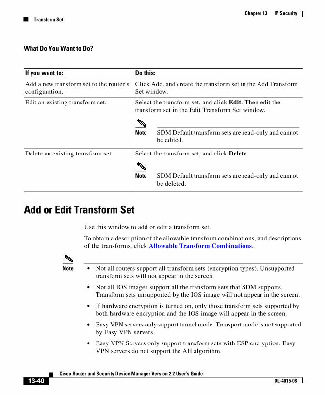
Chapter 13 IP SecurityTransform Set
What Do You Want to Do?
Add or Edit Transform SetUse this window to add or edit a transform set.
To obtain a description of the allowable transform combinations, and descriptions of the transforms, click Allowable Transform Combinations.
Note • Not all routers support all transform sets (encryption types). Unsupported transform sets will not appear in the screen.
• Not all IOS images support all the transform sets that SDM supports. Transform sets unsupported by the IOS image will not appear in the screen.
• If hardware encryption is turned on, only those transform sets supported by both hardware encryption and the IOS image will appear in the screen.
• Easy VPN servers only support tunnel mode. Transport mode is not supported by Easy VPN servers.
• Easy VPN Servers only support transform sets with ESP encryption. Easy VPN servers do not support the AH algorithm.
If you want to: Do this:
Add a new transform set to the router’s configuration.
Click Add, and create the transform set in the Add Transform Set window.
Edit an existing transform set. Select the transform set, and click Edit. Then edit the transform set in the Edit Transform Set window.
Note SDM Default transform sets are read-only and cannot be edited.
Delete an existing transform set. Select the transform set, and click Delete.
Note SDM Default transform sets are read-only and cannot be deleted.
13-40Cisco Router and Security Device Manager Version 2.2 User’s Guide
OL-4015-08

Chapter 13 IP SecurityTransform Set
• Easy VPN Servers do not support ESP-SEAL encryption.
Name of this transform set
This can be any name that you want. The name does not have to match the name in the transform set that the peer uses, but it may be helpful to give corresponding transform sets the same name.
Data integrity and encryption (ESP)
Check this box if you want to provide Encapsulating Security Payload (ESP) data integrity and encryption.
Integrity Algorithm
Select one of the following:
• ESP_MD5_HMAC. Message Digest 5.
• ESP_SHA_HMAC. Security Hash Algorithm.
Encryption
SDM recognizes the following ESP encryption types:
• ESP_DES. Encapsulating Security Payload (ESP), Data Encryption Standard (DES). DES supports 56-bit encryption.
• ESP_3DES. ESP, Triple DES. This is a stronger form of encryption than DES, supporting 168-bit encryption.
• ESP_AES_128. ESP, Advanced Encryption Standard (AES). Encryption with a 128-bit key. AES provides greater security than DES and is computationally more efficient than 3DES.
• ESP_AES_192. ESP, AES encryption with a 192-bit key.
• ESP_AES_256. ESP, AES encryption with a 256-bit key.
• ESP_SEAL—ESP with the 160-bit encryption key Software Encryption Algorithm (SEAL) encryption algorithm. SEAL (Software Encryption Algorithm) is an alternative algorithm to software-based Data Encryption Standard (DES), Triple DES (3DES), and Advanced Encryption Standard (AES). SEAL encryption uses a 160-bit encryption key and has a lower impact to the CPU when compared to other software-based algorithms.
13-41Cisco Router and Security Device Manager Version 2.2 User’s Guide
OL-4015-08

Chapter 13 IP SecurityTransform Set
• ESP_NULL. Null encryption algorithm, but encryption transform used.
Note The types of ESP encryption available depend on the router. Depending on the type of router you are configuring, one or more of these encryption types may not be available.
Data and address integrity without encryption (AH)
This check box and the fields below it appear if you click Show Advanced.
Check this box if you want the router to provide Authentication Header (AH) data and address integrity. The authentication header will not be encrypted.
Integrity Algorithm
Select one of the following:
• AH_MD5_HMAC—Message Digest 5.
• AH_SHA_HMAC—Security Hash Algorithm.
Mode
Select which parts of the traffic you want to encrypt:
• Transport. Encrypt data only—Transport mode is used when both endpoints support IPsec; this mode places the AH or ESP after the original IP header; thus, only the IP payload is encrypted. This method allows users to apply network services such as quality-of-service (QoS) controls to encrypted packets. Transport mode should be used only when the destination of the data is always the remote VPN peer.
• Tunnel. Encrypt data and IP header—Tunnel mode provides stronger protection than transport mode. Because the entire IP packet is encapsulated within AH or ESP, a new IP header is attached, and the entire datagram can be encrypted. Tunnel mode allows network devices such as a router to act as an IPsec proxy for multiple VPN users; tunnel mode should be used in those configurations.
IP Compression (COMP-LZS)
Check this box if you want to use data compression.
13-42Cisco Router and Security Device Manager Version 2.2 User’s Guide
OL-4015-08
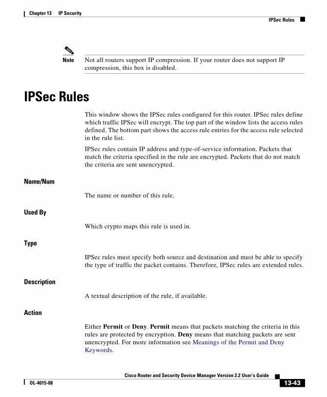
Chapter 13 IP SecurityIPSec Rules
Note Not all routers support IP compression. If your router does not support IP compression, this box is disabled.
IPSec RulesThis window shows the IPSec rules configured for this router. IPSec rules define which traffic IPSec will encrypt. The top part of the window lists the access rules defined. The bottom part shows the access rule entries for the access rule selected in the rule list.
IPSec rules contain IP address and type-of-service information. Packets that match the criteria specified in the rule are encrypted. Packets that do not match the criteria are sent unencrypted.
Name/Num
The name or number of this rule.
Used By
Which crypto maps this rule is used in.
Type
IPSec rules must specify both source and destination and must be able to specify the type of traffic the packet contains. Therefore, IPSec rules are extended rules.
Description
A textual description of the rule, if available.
Action
Either Permit or Deny. Permit means that packets matching the criteria in this rules are protected by encryption. Deny means that matching packets are sent unencrypted. For more information see Meanings of the Permit and Deny Keywords.
13-43Cisco Router and Security Device Manager Version 2.2 User’s Guide
OL-4015-08

Chapter 13 IP SecurityIPSec Rules
Source
An IP address or keyword that specifies the source of the traffic. Any specifies that the source can be any IP address. An IP address in this column may appear alone, or it may be followed by a wildcard mask. If present, the wildcard mask specifies the portions of the IP address that the source IP address must match. For more information, see IP Addresses and Subnet Masks.
Destination
An IP address or keyword that specifies the destination of the traffic. Any specifies that the destination can be any IP address. An IP address in this column may appear alone, or it may be followed by a wildcard mask. If present, the wildcard mask specifies the portions of the IP address that the destination IP address must match.
Service
The type of traffic that the packet must contain.
What Do You Want to Do?
If you want to: Do this:
See the access rule entries for a particular rule.
Select the rule in the rule list. The entries for that rule appear in the lower box.
Add an IPSec rule. Click Add, and create the rule in the rule window displayed.
Delete an IPSec rule. Select the rule in the rule list, and click Delete.
Delete a particular rule entry. Select the rule in the rule list, and click Edit. Then, delete the entry in the rule window displayed.
Apply an IPSec rule to an interface. Apply the rule in the interface configuration window.
13-44Cisco Router and Security Device Manager Version 2.2 User’s Guide
OL-4015-08

Cisco Router and Security DeOL-4015-08
C H A P T E R14
Internet Key ExchangeThe help topics in this section describe the Internet Key Exchange (IKE) configuration screens.
Internet Key Exchange (IKE)Internet Key Exchange (IKE) is a standard method for arranging for secure, authenticated communications. IKE establishes session keys (and associated cryptographic and networking configuration) between two hosts across the network.
SDM lets you create IKE policies that will protect the identities of peers during authentication. SDM also lets you create pre-shared keys that peers exchange.
What Do You Want to Do?
If you want to: Do this:
Learn more about IKE. Click More About IKE.
Enable IKE.
You must enable IKE for VPN connections to use IKE negotiations.
Click Global Settings, and then click Edit to enable IKE and make other global settings for IKE.
14-45vice Manager Version 2.2 User’s Guide
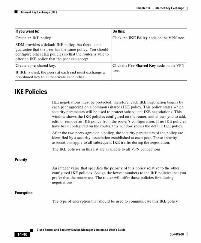
Chapter 14 Internet Key ExchangeInternet Key Exchange (IKE)
IKE PoliciesIKE negotiations must be protected; therefore, each IKE negotiation begins by each peer agreeing on a common (shared) IKE policy. This policy states which security parameters will be used to protect subsequent IKE negotiations. This window shows the IKE policies configured on the router, and allows you to add, edit, or remove an IKE policy from the router’s configuration. If no IKE policies have been configured on the router, this window shows the default IKE policy.
After the two peers agree on a policy, the security parameters of the policy are identified by a security association established at each peer. These security associations apply to all subsequent IKE traffic during the negotiation.
The IKE policies in this list are available to all VPN connections.
Priority
An integer value that specifies the priority of this policy relative to the other configured IKE policies. Assign the lowest numbers to the IKE policies that you prefer that the router use. The router will offer those policies first during negotiations.
Encryption
The type of encryption that should be used to communicate this IKE policy.
Create an IKE policy.
SDM provides a default IKE policy, but there is no guarantee that the peer has the same policy. You should configure other IKE policies so that the router is able to offer an IKE policy that the peer can accept.
Click the IKE Policy node on the VPN tree.
Create a pre-shared key.
If IKE is used, the peers at each end must exchange a pre-shared key to authenticate each other.
Click the Pre-Shared Key node on the VPN tree.
If you want to: Do this:
14-46Cisco Router and Security Device Manager Version 2.2 User’s Guide
OL-4015-08

Chapter 14 Internet Key ExchangeInternet Key Exchange (IKE)
Hash
The authentication algorithm for negotiation. There are two possible values:
• Secure Hash Algorithm (SHA)
• Message Digest 5 (MD5)
Authentication
The authentication method to be used.
• Pre-SHARE. Authentication will be performed using pre-shared keys.
• RSA_SIG. Authentication will be performed using digital signatures.
Type
Either SDM_DEFAULT or User Defined. SDM_DEFAULT policies cannot be edited.
What Do You Want to Do?
If you want to: Do this:
Learn more about IKE policies. See More About IKE Policies.
Add an IKE policy to the router’s configuration.
SDM provides a default IKE policy, but there is no guarantee that the peer has the same policy. You should configure other IKE policies so that the router is able to offer an IKE policy that the peer can accept.
Click Add, and configure a new IKE policy in the Add IKE policy window.
Edit an existing IKE policy. Choose the IKE policy that you want to edit, and click Edit. Then edit the IKE policy in the Edit IKE policy window.
Default IKE policies are read only. They cannot be edited.
Remove an IKE policy from the router’s configuration.
Choose the IKE policy that you want to remove, and click Remove.
14-47Cisco Router and Security Device Manager Version 2.2 User’s Guide
OL-4015-08

Chapter 14 Internet Key ExchangeInternet Key Exchange (IKE)
Add or Edit IKE Policy
Add or edit an IKE policy in this window.
Note • Not all routers support all encryption types. Unsupported types will not appear in the screen.
• Not all IOS images support all the encryption types that SDM supports. Types unsupported by the IOS image will not appear in the screen.
• If hardware encryption is turned on, only those encryption types supported by both hardware encryption and the IOS image will appear in the screen.
Priority
An integer value that specifies the priority of this policy relative to the other configured IKE policies. Assign the lowest numbers to the IKE policies that you prefer that the router use. The router will offer those policies first during negotiations.
Encryption
The type of encryption that should be used to communicate this IKE policy. SDM supports a variety of encryption types, listed in order of security. The more secure an encryption type, the more processing time it requires.
Note If your router does not support an encryption type, the type will not appear in the list.
SDM supports the following types of encryption:
• Data Encryption Standard (DES)—This form of encryption supports 56-bit encryption.
• Triple Data Encryption Standard (3DES)—This is a stronger form of encryption than DES, supporting 168-bit encryption.
• AES-128—Advanced Encryption Standard (AES) encryption with a 128-bit key. AES provides greater security than DES and is computationally more efficient than triple DES.
14-48Cisco Router and Security Device Manager Version 2.2 User’s Guide
OL-4015-08

Chapter 14 Internet Key ExchangeInternet Key Exchange (IKE)
• AES-192—Advanced Encryption Standard (AES) encryption with a 192-bit key.
• AES-256—Advanced Encryption Standard (AES) encryption with a 256-bit key.
Hash
The authentication algorithm to be used for the negotiation. There are two options:
• Secure Hash Algorithm (SHA)
• Message Digest 5 (MD5)
Authentication
The authentication method to be used.
• Pre-SHARE. Authentication will be performed using pre-shared keys.
• RSA_SIG. Authentication will be performed using digital signatures.
D-H Group
Diffie-Hellman (D-H) Group. Diffie-Hellman is a public-key cryptography protocol that allows two routers to establish a shared secret over an unsecure communications channel. The options are as follows:
• group1—768-bit D-H Group. D-H Group 1.
• group2—1024-bit D-H Group. D-H Group 2. This group provides more security than group 1, but requires more processing time.
• group5—1536-bit D-H Group. D-H Group 5. This group provides more security than group 2, but requires more processing time.
Note • If your router does not support group5, it will not appear in the list.
• Easy VPN servers do not support D-H Group 1.
14-49Cisco Router and Security Device Manager Version 2.2 User’s Guide
OL-4015-08

Chapter 14 Internet Key ExchangeInternet Key Exchange (IKE)
Lifetime
This is the lifetime of the security association, in hours, minutes and seconds. The default is one day, or 24:00:00.
IKE Pre-shared KeysThis window allows you to view, add, edit, and remove IKE pre-shared keys in the router’s configuration. A pre-shared key is exchanged with a remote peer during IKE negotiation. Both peers must be configured with the same key.
Icon
Peer IP/Name
An IP address or name of a peer with whom this key is shared. If an IP address is supplied, it can specify all peers in a network or subnetwork, or just an individual host. If a name is specified, then the key is shared by only the named peer.
Network Mask
The network mask specifies how much of the peer IP address is used for the network address and how much is used for the host address. A network mask of 255.255.255.255 indicates that the peer IP address is an address for a specific host. A network mask containing zeros in the least significant bytes indicates that the peer IP address is a network or subnet address. For example a network mask of 255.255.248.0 indicates that the first 22 bits of the address are used for the network address and that the last 10 bits are for the host part of the address.
Pre-Shared Key
The pre-shared key is not readable in SDM windows. If you need to examine the pre shared key, go to View->Running Config. This will display the running configuration. The key is contained in the crypto isakmp key command.
If a pre-shared key is read-only, the read-only icon appears in this column. A pre-shared key will be marked as read-only if it is configured with the no-xauth CLI option
14-50Cisco Router and Security Device Manager Version 2.2 User’s Guide
OL-4015-08
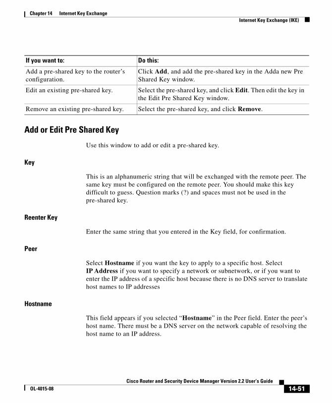
Chapter 14 Internet Key ExchangeInternet Key Exchange (IKE)
Add or Edit Pre Shared Key
Use this window to add or edit a pre-shared key.
Key
This is an alphanumeric string that will be exchanged with the remote peer. The same key must be configured on the remote peer. You should make this key difficult to guess. Question marks (?) and spaces must not be used in the pre-shared key.
Reenter Key
Enter the same string that you entered in the Key field, for confirmation.
Peer
Select Hostname if you want the key to apply to a specific host. Select IP Address if you want to specify a network or subnetwork, or if you want to enter the IP address of a specific host because there is no DNS server to translate host names to IP addresses
Hostname
This field appears if you selected “Hostname” in the Peer field. Enter the peer’s host name. There must be a DNS server on the network capable of resolving the host name to an IP address.
If you want to: Do this:
Add a pre-shared key to the router’s configuration.
Click Add, and add the pre-shared key in the Adda new Pre Shared Key window.
Edit an existing pre-shared key. Select the pre-shared key, and click Edit. Then edit the key in the Edit Pre Shared Key window.
Remove an existing pre-shared key. Select the pre-shared key, and click Remove.
14-51Cisco Router and Security Device Manager Version 2.2 User’s Guide
OL-4015-08

Chapter 14 Internet Key ExchangeInternet Key Exchange (IKE)
IP Address/Subnet Mask
These fields appear if you selected “IP Address” in the Peer field. Enter the IP address of a network or subnet in the IP Address field. The pre-shared key will apply to all peers in that network or subnet. For more information, refer to IP Addresses and Subnet Masks.
Enter a subnet mask if the IP address you entered is a subnet address, and not the address of a specific host.
User Authentication [Xauth]
Check this box if site-to-site VPN peers use XAuth to authenticate themselves. If Xauth authenticationn is enabled in VPN Global Settings, it is enabled for site-to-site peers as well as for Easy VPN connections.
14-52Cisco Router and Security Device Manager Version 2.2 User’s Guide
OL-4015-08

Cisco Router and Security DeOL-4015-08
C H A P T E R15
VPN TroubleshootingSDM can troubleshoot VPN connections that you have configured. SDM reports the success or failure of the connection tests, and when tests have failed, recommends actions that you can take to correct connection problems.
The following link provides information on VPN troubleshooting using the CLI.
http://www.cisco.com/univercd/cc/td/doc/product/rtrmgmt/cw2000/cw2000_b/vpnman/vms_2_2/rmc13/useguide/u13_rtrb.htm
VPN TroubleshootingThis window appear when you are troubleshooting a site-to-site VPN, a GRE over IPSec tunnel, an Easy VPN remote connection, or an Easy VPN server connection.
Note VPN Troubleshooting will not troubleshoot more than two peers for site-to-site VPN, GRE over IPsec, or Easy VPN client connections.
Tunnel Details
This box provides the VPN tunnel details.
Interface
Interface to which the VPN tunnel is configured.
15-53vice Manager Version 2.2 User’s Guide

Chapter 15 VPN TroubleshootingVPN Troubleshooting
Peer
The IP address or host name of the devices at the other end of the VPN connection.
Summary
Click this button if you want to view the summarized troubleshooting information.
Details
Click this button if you want to view the detailed troubleshooting information.
Activity
This column displays the troubleshooting activities.
Status
Displays the status of each troubleshooting activity by the following icons and text alerts:
Failure Reason(s)
This box provides the possible reason(s) for the VPN tunnel failure.
Recommended action(s)
This box provides a possible action/solution to rectify the problem.
Close Button
Click this button to close the window.
The connection is up.
The connection is down.
Test is successful.
Test failed.
15-54Cisco Router and Security Device Manager Version 2.2 User’s Guide
OL-4015-08

Chapter 15 VPN TroubleshootingVPN Troubleshooting: Specify Easy VPN Client
Test Specific Client Button
This button is enabled if you are testing connections for an Easy VPN server configured on the router. Click this button and specify the client to which you want to test connectivity.
This button is disabled in the following circumstances:
• The Basic testing is not done or has not completed successfully.
• The IOS image does not support the required debugging commands.
• The view used to launch SDM does not have root privileges.
What Do You Want to Do?
VPN Troubleshooting: Specify Easy VPN ClientThis window allows you to specify the Easy VPN client which you want to debug.
IP Address
Enter IP address of Easy VPN client you want to debug.
Listen for request for X minutes
Enter the time duration for which Easy VPN Server has to listen to requests from Easy VPN client.
If you want to: Do this:
Troubleshoot the VPN connection. Click Start button.
When test is running, Start button label will change to Stop. You have option to abort the troubleshooting while test is in progress.
Save the test report. Click Save Report button to save the test report in HTML format.
This button is disabled when the test is in progress.
15-55Cisco Router and Security Device Manager Version 2.2 User’s Guide
OL-4015-08
Chapter 15 VPN TroubleshootingVPN Troubleshooting: Generate Traffic
Continue Button
After selecting the traffic generation type you want, click this button to continue testing.
Close Button
Click this button to close the window.
VPN Troubleshooting: Generate TrafficThis window allows you to generate site-to-site VPN or Easy VPN traffic for debugging. You can allow SDM to generate VPN traffic or you can generate VPN traffic yourself.
VPN traffic on this connection is defined as
This area lists current VPN traffic on the interface.
Action
This column denotes whether the type of traffic is allowed in the interface.
Source
Source IP address.
Destination
Destination IP address.
Service
This column lists the type of traffic on the interface.
Log
This column indicates whether logging is enabled for this traffic.
Attributes
Any additional attributes defined.
15-56Cisco Router and Security Device Manager Version 2.2 User’s Guide
OL-4015-08

Chapter 15 VPN TroubleshootingVPN Troubleshooting: Generate GRE Traffic
Have SDM generate VPN Traffic
Select this option if you want SDM to generate VPN traffic on the interface for debugging.
Note SDM will not generate VPN traffic when the VPN tunnel traffic is from non-IP based Access Control List (ACL) or when the applied and current CLI View is not root view.
Enter the IP address of a host in the source network
Enter the host IP address in the source network.
Enter the IP address of a host in the destination network
Enter the host IP address in the destination network.
I will generate VPN traffic from the source network
Select this option if you want to generate VPN traffic from the source network.
Wait interval time
Enter the amount of time in seconds that the Easy VPN Server is to wait for you to generate source traffic. Be sure to give yourself enough time to switch to other systems to generate traffic.
Continue Button
After selecting the traffic generation type you want, click this button to continue testing.
Close Button
Click this button to close the window.
VPN Troubleshooting: Generate GRE TrafficThis screen appears if you are generating GRE over IPSec traffic.
15-57Cisco Router and Security Device Manager Version 2.2 User’s Guide
OL-4015-08
Chapter 15 VPN TroubleshootingSDM Warning: SDM will enable router debugs...
Have SDM generate VPN Traffic
Select this option if you want SDM to generate VPN traffic on the interface for debugging.
Enter the remote tunnel IP address
Enter the IP address of the remote GRE tunnel. Do not use the address of the remote interface.
I will generate VPN traffic from the source network
Select this option if you want to generate VPN traffic from the source network.
Wait interval time
Enter the amount of time in seconds that the Easy VPN Server is to wait for you to generate source traffic. Be sure to give yourself enough time to switch to other systems to generate traffic.
Continue Button
After selecting the traffic generation type you want, click this button to continue testing.
Close Button
Click this button to close the window.
SDM Warning: SDM will enable router debugs...This window appears when SDM is ready to begin advanced troubleshooting. Advanced troubleshooting involves delivering debug commands to the router waiting for results to report, and then removing the debug commands so that router performance is not further affected.
This message is displayed because this process can take several minutes and may affect router performance.
15-58Cisco Router and Security Device Manager Version 2.2 User’s Guide
OL-4015-08
Cisco Router and Security DeOL-4015-08
C H A P T E R16
Security AuditSecurity Audit is a feature that examines your existing router configurations and then updates your router in order to make your router and network more secure. Security Audit is based on the Cisco IOS AutoSecure feature; it performs checks on and assists in configuration of almost all of the AutoSecure functions. For a complete list of the functions that Security Audit checks for, and for a list of the few AutoSecure features unsupported by Security Audit, see the topic SDM and Cisco IOS AutoSecure.
Security Audit operates in one of two modes—the Security Audit wizard, which lets you choose which potential security-related configuration changes to implement on your router, and One-Step Lockdown, which automatically makes all recommended security-related configuration changes.
Perform Security Audit
This option starts the Security Audit wizard. The Security Audit wizard tests your router configuration to determine if any potential security problems exist in the configuration, and then presents you with a screen that lets you determine which of those security problems you want to fix. Once determined, the Security Audit wizard will make the necessary changes to the router configuration to fix those problems.
To have SDM perform a security audit and then fix the problems it has found:
Step 1 In the left frame, select Security Audit.
Step 2 Click Perform Security Audit.
16-1vice Manager Version 2.2 User’s Guide

Chapter 16 Security Audit
The Welcome page of the Security Audit wizard appears.
Step 3 Click Next>.
The Security Audit Interface Configuration page appears.
Step 4 The Security Audit wizard needs to know which of your router interfaces connect to your inside network and which connect outside of your network. For each interface listed, check either the Inside or Outside check box to indicate where the interface connects.
Step 5 Click Next>.
The Security Audit wizard tests your router configuration to determine which possible security problems may exist. A screen showing the progress of this action appears, listing all of the configuration options being tested for, and whether or not the current router configuration passes those tests.
If you want to save this report to a file, click Save Report.
Step 6 Click Close.
The Security Audit Report Card screen appears, showing a list of possible security problems.
Step 7 Check the Fix it boxes next to any problems that you want Cisco Router and Security Device Manager (SDM) to fix. For a description of the problem and a list of the Cisco IOS commands that will be added to your configuration, click the problem description to display a help page about that problem.
Step 8 Click Next>.
Step 9 The Security Audit wizard may display one or more screens requiring you to enter information to fix certain problems. Enter the information as required and click Next> for each of those screens.
Step 10 The Summary page of the wizard shows a list of all the configuration changes that Security Audit will make. Click Finish to deliver those changes to your router.
16-2Cisco Router and Security Device Manager Version 2.2 User’s Guide
OL-4015-08
Chapter 16 Security Audit
One-Step Lockdown
This option tests you router configuration for any potential security problems and automatically makes any necessary configuration changes to correct any problems found. The conditions checked for and, if needed, corrected are as follows:
• Disable Finger Service
• Disable PAD Service
• Disable TCP Small Servers Service
• Disable UDP Small Servers Service
• Disable IP BOOTP Server Service
• Disable IP Identification Service
• Disable CDP
• Disable IP Source Route
• Enable Password Encryption Service
• Enable TCP Keepalives for Inbound Telnet Sessions
• Enable TCP Keepalives for Outbound Telnet Sessions
• Enable Sequence Numbers and Time Stamps on Debugs
• Enable IP CEF
• Disable IP Gratuitous ARPs
• Set Minimum Password Length to Less Than 6 Characters
• Set Authentication Failure Rate to Less Than 3 Retries
• Set TCP Synwait Time
• Set Banner
• Enable Logging
• Set Enable Secret Password
• Disable SNMP
• Set Scheduler Interval
• Set Scheduler Allocate
• Set Users
• Enable Telnet Settings
16-3Cisco Router and Security Device Manager Version 2.2 User’s Guide
OL-4015-08

Chapter 16 Security AuditWelcome Page
• Enable NetFlow Switching
• Disable IP Redirects
• Disable IP Proxy ARP
• Disable IP Directed Broadcast
• Disable MOP Service
• Disable IP Unreachables
• Disable IP Mask Reply
• Disable IP Unreachables on NULL Interface
• Enable Unicast RPF on Outside Interfaces
• Enable Firewall on All of the Outside Interfaces
• Set Access Class on HTTP Server Service
• Set Access Class on VTY Lines
• Enable SSH for Access to the Router
Welcome PageThis screen describes the Security Audit wizard and the changes the wizard will attempt to make to your router configuration.
Interface Selection PageThis screen displays a list of all interfaces and requires you to identify which router interfaces are “outside” interfaces, that is, interfaces that connect to unsecure networks such as the Internet. By identifying which interfaces are outside interfaces, Security Configuration knows on which interfaces to configure firewall security features.
Interface Column
This column lists each of the router interfaces.
16-4Cisco Router and Security Device Manager Version 2.2 User’s Guide
OL-4015-08
Chapter 16 Security AuditReport Card Page
Outside Column
This column displays a check box for each interface listed in the Interface column. Check the check box for each interface that connects to a network outside of your network, such as the Internet.
Inside Column
This column displays a check box for each interface listed in the Interface column. Check the check box for each interface that connects directly to your local network and is thus protected from the Internet by your firewall.
Report Card PageThe Report Card popup page displays a list of recommended configuration changes that, if made, make the network more secure. The Save button, enabled after all checks are made, lets you save the report card to a file that you can print or email. Clicking Close displays a dialog that lists the reported security problems, and that can list security configurations that SDM can undo.
Fix It PageThis page displays the configuration changes recommended in the Report Card page. Use the Select an Option list to display the security problems SDM can fix, or the security configurations SDM can undo.
Select an Option: Fix the security problems
The Report Card screen displays a list of recommended configuration changes that will make your router and network more secure. The potential security problems in your router configuration are listed in the left column. To get more information about a potential problem, click the problem. Online help will display a more detailed description of the problem and the recommended configuration changes. To correct all of the potential problems, click Fix All, and then click Next> to continue. To correct individual security issues, check the Fix It check box next to the issue or issues that you want to correct, and then click Next> to continue the Security Audit Wizard. The Security Audit will correct the problems
16-5Cisco Router and Security Device Manager Version 2.2 User’s Guide
OL-4015-08

Chapter 16 Security AuditFix It Page
you selected, collecting further input from you as necessary, and will then display a list of the new configuration commands that will be added to the router configuration.
Fix All
Click this button to place a check mark next to all of the potential security problems listed on the Report Card screen.
Select an option: Undo Security Configurations
When this option is selected, SDM displays the security configurations that it can undo. To have SDM undo all the security configurations, click Undo All. To specify a security configuration that you want to undo, check the Undo box next to it. Click Next> after you have specified which security configurations to undo. You must select at least one security configuration to undo.
Undo All
Click the button to place a checkmark next to all the security configurations that SDM can undo.
To see which security configurations SDM can undo, click:
Security Configurations SDM Can Undo
I want SDM to fix some problems, but undo other security configurations
If you want SDM to fix some security issues but undo other security configurations that you do not need, you can run the Security Audit wizard once to specify the problems to fix, and then run it again so that you can select the security configurations you want to undo.
Disable Finger ServiceSecurity Audit disables the finger service whenever possible. Finger is used to find out which users are logged into a network device. Although this information is not usually tremendously sensitive, it can sometimes be useful to an attacker.
In addition, the finger service can be used in a specific type of Denial-of-Service (DoS) attack called “Finger of death,” which involves sending a finger request to a specific computer every minute, but never disconnecting.
16-6Cisco Router and Security Device Manager Version 2.2 User’s Guide
OL-4015-08

Chapter 16 Security AuditFix It Page
The configuration that will be delivered to the router to disable the Finger service is as follows:
no service finger
This fix can be undone. To learn how, click Undoing Security Audit Fixes..
Disable PAD ServiceSecurity Audit disables all packet assembler/disassembler (PAD) commands and connections between PAD devices and access servers whenever possible.
The configuration that will be delivered to the router to disable PAD is as follows:
no service pad
This fix can be undone. To learn how, click Undoing Security Audit Fixes..
Disable TCP Small Servers ServiceSecurity Audit disables small services whenever possible. By default, Cisco devices running Cisco IOS version 11.3 or earlier offer the “small services”: echo, chargen, and discard. (Small services are disabled by default in Cisco IOS software version 12.0 and later.) These services, especially their User Datagram Protocol (UDP) versions, are infrequently used for legitimate purposes, but they can be used to launch DoS and other attacks that would otherwise be prevented by packet filtering.
For example, an attacker might send a Domain Name System (DNS) packet, falsifying the source address to be a DNS server that would otherwise be unreachable, and falsifying the source port to be the DNS service port (port 53). If such a packet were sent to the router’s UDP echo port, the result would be the router sending a DNS packet to the server in question. No outgoing access list checks would be applied to this packet, since it would be considered to be locally generated by the router itself.
Although most abuses of the small services can be avoided or made less dangerous by anti-spoofing access lists, the services should almost always be disabled in any router which is part of a firewall or lies in a security-critical part of the network. Since the services are rarely used, the best policy is usually to disable them on all routers of any description.
16-7Cisco Router and Security Device Manager Version 2.2 User’s Guide
OL-4015-08
Chapter 16 Security AuditFix It Page
The configuration that will be delivered to the router to disable TCP small servers is as follows:
no service tcp-small-servers
This fix can be undone. To learn how, click Undoing Security Audit Fixes.
Disable UDP Small Servers ServiceSecurity Audit disables small services whenever possible. By default, Cisco devices running Cisco IOS version 11.3 or earlier offer the “small services”: echo, chargen, and discard. (Small services are disabled by default in Cisco IOS software version 12.0 and later.) These services, especially their UDP versions, are infrequently used for legitimate purposes, but they can be used to launch DoS and other attacks that would otherwise be prevented by packet filtering.
For example, an attacker might send a DNS packet, falsifying the source address to be a DNS server that would otherwise be unreachable, and falsifying the source port to be the DNS service port (port 53). If such a packet were sent to the router’s UDP echo port, the result would be the router sending a DNS packet to the server in question. No outgoing access list checks would be applied to this packet, since it would be considered to be locally generated by the router itself.
Although most abuses of the small services can be avoided or made less dangerous by anti-spoofing access lists, the services should almost always be disabled in any router which is part of a firewall or lies in a security-critical part of the network. Since the services are rarely used, the best policy is usually to disable them on all routers of any description.
The configuration that will be delivered to the router to disable UDP small servers is as follows:
no service udp-small-servers
Disable IP BOOTP Server ServiceSecurity Audit disables the Bootstrap Protocol (BOOTP) service whenever possible. BOOTP allows both routers and computers to automatically configure necessary Internet information from a centrally maintained server upon startup, including downloading Cisco IOS software. As a result, BOOTP can potentially be used by an attacker to download a copy of a router’s Cisco IOS software.
16-8Cisco Router and Security Device Manager Version 2.2 User’s Guide
OL-4015-08
Chapter 16 Security AuditFix It Page
In addition, the BOOTP service is vulnerable to DoS attacks; therefore it should be disabled or filtered via a firewall for this reason as well.
The configuration that will be delivered to the router to disable BOOTP is as follows:
no ip bootp server
This fix can be undone. To learn how, click Undoing Security Audit Fixes.
Disable IP Identification ServiceSecurity Audit disables identification support whenever possible. Identification support allows you to query a TCP port for identification. This feature enables an unsecure protocol to report the identity of a client initiating a TCP connection and a host responding to the connection. With identification support, you can connect a TCP port on a host, issue a simple text string to request information, and receive a simple text-string reply.
It is dangerous to allow any system on a directly connected segment to learn that the router is a Cisco device and to determine the model number and the Cisco IOS software version being run. This information may be used to design attacks against the router.
The configuration that will be delivered to the router to disable the IP identification service is as follows:
no ip identd
This fix can be undone. To learn how, click Undoing Security Audit Fixes.
Disable CDPSecurity Audit disables Cisco Discovery Protocol (CDP) whenever possible. CDP is a proprietary protocol that Cisco routers use to identify each other on a LAN segment. This is dangerous in that it allows any system on a directly connected segment to learn that the router is a Cisco device and to determine the model number and the Cisco IOS software version being run. This information may be used to design attacks against the router.
The configuration that will be delivered to the router to disable CDP is as follows:
no cdp run
16-9Cisco Router and Security Device Manager Version 2.2 User’s Guide
OL-4015-08

Chapter 16 Security AuditFix It Page
This fix can be undone. To learn how, click Undoing Security Audit Fixes.
Disable IP Source RouteSecurity Audit disables IP source routing whenever possible. The IP protocol supports source routing options that allow the sender of an IP datagram to control the route that the datagram will take toward its ultimate destination, and generally the route that any reply will take. These options are rarely used for legitimate purposes in networks. Some older IP implementations do not process source-routed packets properly, and it may be possible to crash machines running these implementations by sending them datagrams with source routing options.
Disabling IP source routing will cause a Cisco router to never forward an IP packet that carries a source routing option.
The configuration that will be delivered to the router to disable IP source routing is as follows:
no ip source-route
This fix can be undone. To learn how, click Undoing Security Audit Fixes.
Enable Password Encryption ServiceSecurity Audit enables password encryption whenever possible. Password encryption directs the Cisco IOS software to encrypt the passwords, Challenge Handshake Authentication Protocol (CHAP) secrets, and similar data that are saved in its configuration file. This is useful for preventing casual observers from reading passwords, for example, when they happen to look at the screen over an administrator’s shoulder.
The configuration that will be delivered to the router to enable password encryption is as follows:
service password-encryption
This fix can be undone. To learn how, click Undoing Security Audit Fixes.
16-10Cisco Router and Security Device Manager Version 2.2 User’s Guide
OL-4015-08
Chapter 16 Security AuditFix It Page
Enable TCP Keepalives for Inbound Telnet SessionsSecurity Audit enables TCP keep alive messages for both inbound and outbound Telnet sessions whenever possible. Enabling TCP keep alives causes the router to generate periodic keep alive messages, letting it detect and drop broken Telnet connections.
The configuration that will be delivered to the router to enable TCP keep alives for inbound Telnet sessions is as follows:
service tcp-keepalives-in
This fix can be undone. To learn how, click Undoing Security Audit Fixes.
Enable TCP Keepalives for Outbound Telnet SessionsSecurity Audit enables TCP keep alive messages for both inbound and outbound Telnet sessions whenever possible. Enabling TCP keep alives causes the router to generate periodic keep alive messages, letting it detect and drop broken Telnet connections.
The configuration that will be delivered to the router to enable TCP keep alives for outbound Telnet sessions is as follows:
service tcp-keepalives-out
This fix can be undone. To learn how, click Undoing Security Audit Fixes.
Enable Sequence Numbers and Time Stamps on DebugsSecurity Audit enables sequence numbers and time stamps on all debug and log messages whenever possible. Time stamps on debug and log messages indicate the time and date that the message was generated. Sequence numbers indicate the sequence in which messages that have identical time stamps were generated. Knowing the timing and sequence that messages are generated is an important tool in diagnosing potential attacks.
The configuration that will be delivered to the router to enable time stamps and sequence numbers is as follows:
service timestamps debug datetime localtime show-timezone msecservice timestamps log datetime localtime show-timeout msec
16-11Cisco Router and Security Device Manager Version 2.2 User’s Guide
OL-4015-08
Chapter 16 Security AuditFix It Page
service sequence-numbers
Enable IP CEFSecurity Audit enables Cisco Express Forwarding (CEF) or Distributed Cisco Express Forwarding (DCEF) whenever possible. Because there is no need to build cache entries when traffic starts arriving at new destinations, CEF behaves more predictably than other modes when presented with large volumes of traffic addressed to many destinations. Routes configured for CEF perform better under SYN attacks than routers using the traditional cache.
The configuration that will be delivered to the router to enable CEF is as follows:
ip cef
Disable IP Gratuitous ARPsSecurity Audit disables IP gratuitous Address Resolution Protocol (ARP) requests whenever possible. A gratuitous ARP is an ARP broadcast in which the source and destination MAC addresses are the same. It is used primarily by a host to inform the network about its IP address. A spoofed gratuitous ARP message can cause network mapping information to be stored incorrectly, causing network malfunction.
To disable gratuitous ARPs, the following configuration will be delivered to the router:
no ip gratuitous-arps
This fix can be undone. To learn how, click Undoing Security Audit Fixes.
Set Minimum Password Length to Less Than 6 CharactersSecurity Audit configures your router to require a minimum password length of six characters whenever possible. One method attackers use to crack passwords is to try all possible combinations of characters until the password is discovered. Longer passwords have exponentially more possible combinations of characters, making this method of attack much more difficult.
16-12Cisco Router and Security Device Manager Version 2.2 User’s Guide
OL-4015-08
Chapter 16 Security AuditFix It Page
This configuration change will require every password on the router, including the user, enable, secret, console, AUX, tty, and vty passwords, to be at least six characters in length. This configuration change will be made only if the Cisco IOS version running on your router supports the minimum password length feature.
The configuration that will be delivered to the router is as follows:
security passwords min-length <6>
Set Authentication Failure Rate to Less Than 3 RetriesSecurity Audit configures your router to lock access after three unsuccessful login attempts whenever possible. One method of cracking passwords, called the “dictionary” attack, is to use software that attempts to log in using every word in a dictionary. This configuration causes access to the router to be locked for a period of 15 seconds after three unsuccessful login attempts, disabling the dictionary method of attack. In addition to locking access to the router, this configuration causes a log message to be generated after three unsuccessful login attempts, warning the administrator of the unsuccessful login attempts.
The configuration that will be delivered to the router to lock router access after three unsuccessful login attempts is as follows:
security authentication failure rate <3>
Set TCP Synwait TimeSecurity Audit sets the TCP synwait time to 10 seconds whenever possible. The TCP synwait time is a value that is useful in defeating SYN flooding attacks, a form of Denial-of-Service (DoS) attack. A TCP connection requires a three-phase handshake to initially establish the connection. A connection request is sent by the originator, an acknowledgement is sent by the receiver, and then an acceptance of that acknowledgement is sent by the originator. Once this three-phase handshake is complete, the connection is complete and data transfer can begin. A SYN flooding attack sends repeated connection requests to a host, but never sends the acceptance of acknowledgements that complete the connections, creating increasingly more incomplete connections at the host. Because the buffer for incomplete connections is usually smaller than the buffer for completed
16-13Cisco Router and Security Device Manager Version 2.2 User’s Guide
OL-4015-08

Chapter 16 Security AuditFix It Page
connections, this can overwhelm and disable the host. Setting the TCP synwait time to 10 seconds causes the router to shut down an incomplete connection after 10 seconds, preventing the buildup of incomplete connections at the host.
The configuration that will be delivered to the router to set the TCP synwait time to 10 seconds is as follows:
ip tcp synwait-time <10>
Set BannerSecurity Audit configures a text banner whenever possible. In some jurisdictions, civil and/or criminal prosecution of crackers who break into your systems is made much easier if you provide a banner informing unauthorized users that their use is in fact unauthorized. In other jurisdictions, you may be forbidden to monitor the activities of even unauthorized users unless you have taken steps to notify them of your intent to do so. The text banner is one method of performing this notification.
The configuration that will be delivered to the router to create a text banner is as follows, replacing <company name>, <administrator email address>, and <administrator phone number> with the appropriate values that you enter into Security Audit:
banner ~Authorized access onlyThis system is the property of <company name> Enterprise. Disconnect IMMEDIATELY as you are not an authorized user! Contact <administrator email address> <administrator phone number>.~
Enable LoggingSecurity Audit will enable logging with time stamps and sequence numbers whenever possible. Because it gives detailed information about network events, logging is critical in recognizing and responding to security events. Time stamps and sequence numbers provide information about the date and time and sequence in which network events occur.
The configuration that will be delivered to the router to enable and configure logging is as follows, replacing <log buffer size> and <logging server ip address> with the appropriate values that you enter into Security Audit:
16-14Cisco Router and Security Device Manager Version 2.2 User’s Guide
OL-4015-08

Chapter 16 Security AuditFix It Page
logging console criticallogging trap debugginglogging buffered <log buffer size>logging <logging server ip address>
Set Enable Secret PasswordSecurity Audit will configure the enable secret Cisco IOS command for more secure password protection whenever possible. The enable secret command is used to set the password that grants privileged administrative access to the Cisco IOS system. The enable secret command uses a much more secure encryption algorithm (MD5) to protect that password than the older enable password command. This stronger encryption is an essential means of protecting the router password, and thus network access.
The configuration that will be delivered to the router to configure the command is as follows:
enable secret <>
Disable SNMPSecurity Audit disables the Simple Network Management Protocol (SNMP) whenever possible. SNMP is a network protocol that provides a facility for retrieving and posting data about network performance and processes. It is very widely used for router monitoring, and frequently for router configuration changes as well. Version 1 of the SNMP protocol, however, which is the most commonly used, is often a security risk for the following reasons:
• It uses authentication strings (passwords) called community strings which are stored and sent across the network in plain text.
• Most SNMP implementations send those strings repeatedly as part of periodic polling.
• It is an easily spoofable, datagram-based transaction protocol.
Because SNMP can be used to retrieve a copy of the network routing table, as well as other sensitive network information, Cisco recommends disabling SNMP if your network does not require it. Security Audit will initially request to disable SNMP.
16-15Cisco Router and Security Device Manager Version 2.2 User’s Guide
OL-4015-08

Chapter 16 Security AuditFix It Page
The configuration that will be delivered to the router to disable SNMP is as follows:
no snmp-server
Set Scheduler IntervalSecurity Audit configures the scheduler interval on the router whenever possible. When a router is fast-switching a large number of packets, it is possible for the router to spend so much time responding to interrupts from the network interfaces that no other work gets done. Some very fast packet floods can cause this condition. It may stop administrative access to the router, which is very dangerous when the device is under attack. Tuning the scheduler interval ensures that management access to the router is always available by causing the router to run system processes after the specified time interval even when CPU usage is at 100%.
The configuration that will be delivered to the router to tune the scheduler interval is as follows:
scheduler interval 500
Set Scheduler AllocateOn routers that do not support the command scheduler interval, Security Audit configures the scheduler allocate command whenever possible. When a router is fast-switching a large number of packets, it is possible for the router to spend so much time responding to interrupts from the network interfaces that no other work gets done. Some very fast packet floods can cause this condition. It may stop administrative access to the router, which is very dangerous when the device is under attack. The scheduler allocate command guarantees a percentage of the router CPU processes for activities other than network switching, such as management processes.
The configuration that will be delivered to the router to set the scheduler allocate percentage is as follows:
scheduler allocate 4000 1000
16-16Cisco Router and Security Device Manager Version 2.2 User’s Guide
OL-4015-08
Chapter 16 Security AuditFix It Page
Set UsersSecurity Audit secures the console, AUX, vty, and tty lines by configuring Telnet user accounts to authenticate access to these lines whenever possible. Security Audit will display a dialog box that lets you define user accounts and passwords for these lines.
Enable Telnet SettingsSecurity Audit secures the console, AUX, vty, and tty lines by implementing the following configurations whenever possible:
• Configures transport input and transport output commands to define which protocols can be used to connect to those lines.
• Sets the exec-timeout value to 10 minutes on the console and AUX lines, causing an administrative user to be logged out from these lines after 10 minutes of no activity.
The configuration that will be delivered to the router to secure the console, AUX, vty, and tty lines is as follows:
!line console 0transport output telnetexec-timeout 10login local!line AUX 0transport output telnetexec-timeout 10login local!line vty ….transport input telnetlogin local
Enable NetFlow SwitchingSecurity Audit enables NetFlow switching whenever possible. NetFlow switching is a Cisco IOS feature that enhances routing performance while using Access Control Lists (ACLs) and other features that create and enhance network security.
16-17Cisco Router and Security Device Manager Version 2.2 User’s Guide
OL-4015-08

Chapter 16 Security AuditFix It Page
NetFlow identifies flows of network packets based on the source and destination IP addresses and TCP port numbers. NetFlow then can use just the initial packet of a flow for comparison to ACLs and for other security checks, rather than having to use every packet in the network flow. This enhances performance, allowing you to make use of all of the router security features.
The configuration that will be delivered to the router to enable NetFlow is as follows:
ip route-cache flow
This fix can be undone. To learn how, click Undoing Security Audit Fixes.
Disable IP RedirectsSecurity Audit disables Internet Message Control Protocol (ICMP) redirect messages whenever possible. ICMP supports IP traffic by relaying information about paths, routes, and network conditions. ICMP redirect messages instruct an end node to use a specific router as its path to a particular destination. In a properly functioning IP network, a router will send redirects only to hosts on its own local subnets, no end node will ever send a redirect, and no redirect will ever be traversed more than one network hop. However, an attacker may violate these rules; some attacks are based on this. Disabling ICMP redirects will cause no operational impact to the network, and it eliminates this possible method of attack.
The configuration that will be delivered to the router to disable ICMP redirect messages is as follows:
no ip redirects
Disable IP Proxy ARPSecurity Audit disables proxy Address Resolution Protocol (ARP) whenever possible. ARP is used by the network to convert IP addresses into MAC addresses. Normally ARP is confined to a single LAN, but a router can act as a proxy for ARP requests, making ARP queries available across multiple LAN segments. Because it breaks the LAN security barrier, proxy ARP should be used only between two LANs with an equal security level, and only when necessary.
16-18Cisco Router and Security Device Manager Version 2.2 User’s Guide
OL-4015-08
Chapter 16 Security AuditFix It Page
The configuration that will be delivered to the router to disable proxy ARP is as follows:
no ip proxy-arp
This fix can be undone. To learn how, click Undoing Security Audit Fixes.
Disable IP Directed BroadcastSecurity Audit disables IP directed broadcasts whenever possible. An IP directed broadcast is a datagram which is sent to the broadcast address of a subnet to which the sending machine is not directly attached. The directed broadcast is routed through the network as a unicast packet until it arrives at the target subnet, where it is converted into a link-layer broadcast. Because of the nature of the IP addressing architecture, only the last router in the chain, the one that is connected directly to the target subnet, can conclusively identify a directed broadcast. Directed broadcasts are occasionally used for legitimate purposes, but such use is not common outside the financial services industry.
IP directed broadcasts are used in the extremely common and popular “smurf” Denial-of-Service attack, and they can also be used in related attacks. In a “smurf” attack, the attacker sends ICMP echo requests from a falsified source address to a directed broadcast address, causing all the hosts on the target subnet to send replies to the falsified source. By sending a continuous stream of such requests, the attacker can create a much larger stream of replies, which can completely inundate the host whose address is being falsified.
Disabling IP directed broadcasts causes directed broadcasts that would otherwise be “exploded” into link-layer broadcasts at that interface to be dropped instead.
The configuration that will be delivered to the router to disable IP directed broadcasts is as follows:
no ip directed-broadcast
This fix can be undone. To learn how, click Undoing Security Audit Fixes.
16-19Cisco Router and Security Device Manager Version 2.2 User’s Guide
OL-4015-08

Chapter 16 Security AuditFix It Page
Disable MOP ServiceSecurity Audit will disable the Maintenance Operations Protocol (MOP) on all Ethernet interfaces whenever possible. MOP is used to provide configuration information to the router when communicating with DECNet networks. MOP is vulnerable to various attacks.
The configuration that will be delivered to the router to disable the MOP service on Ethernet interfaces is as follows:
no mop enabled
This fix can be undone. To learn how, click Undoing Security Audit Fixes.
Disable IP UnreachablesSecurity Audit disables Internet Message Control Protocol (ICMP) host unreachable messages whenever possible. ICMP supports IP traffic by relaying information about paths, routes, and network conditions. ICMP host unreachable messages are sent out if a router receives a nonbroadcast packet that uses an unknown protocol, or if the router receives a packet that it is unable to deliver to the ultimate destination because it knows of no route to the destination address. These messages can be used by an attacker to gain network mapping information.
The configuration that will be delivered to the router to disable ICMP host unreachable messages is as follows:
int <all-interfaces>no ip unreachables
This fix can be undone. To learn how, click Undoing Security Audit Fixes.
Disable IP Mask ReplySecurity Audit disables Internet Message Control Protocol (ICMP) mask reply messages whenever possible. ICMP supports IP traffic by relaying information about paths, routes, and network conditions. ICMP mask reply messages are sent when a network devices must know the subnet mask for a particular subnetwork
16-20Cisco Router and Security Device Manager Version 2.2 User’s Guide
OL-4015-08

Chapter 16 Security AuditFix It Page
in the internetwork. ICMP mask reply messages are sent to the device requesting the information by devices that have the requested information. These messages can be used by an attacker to gain network mapping information.
The configuration that will be delivered to the router to disable ICMP mask reply messages is as follows:
no ip mask-reply
This fix can be undone. To learn how, click Undoing Security Audit Fixes.
Disable IP Unreachables on NULL InterfaceSecurity Audit disables Internet Message Control Protocol (ICMP) host unreachable messages whenever possible. ICMP supports IP traffic by relaying information about paths, routes, and network conditions. ICMP host unreachable messages are sent out if a router receives a nonbroadcast packet that uses an unknown protocol, or if the router receives a packet that it is unable to deliver to the ultimate destination because it knows of no route to the destination address. Because the null interface is a packet sink, packets forwarded there will always be discarded and, unless disabled, will generate host unreachable messages. In that case, if the null interface is being used to block a Denial-of-Service attack, these messages flood the local network with these messages. Disabling these messages prevents this situation. In addition, because all blocked packets are forwarded to the null interface, an attacker receiving host unreachable messages could use those messages to determine Access Control List (ACL) configuration.
If the “null 0” interface is configured on your router, Security Audit will deliver the following configuration to the router to disable ICMP host unreachable messages for discarded packets or packets routed to the null interface is as follows:
int null 0no ip unreachables
This fix can be undone. To learn how, click Undoing Security Audit Fixes.
16-21Cisco Router and Security Device Manager Version 2.2 User’s Guide
OL-4015-08

Chapter 16 Security AuditFix It Page
Enable Unicast RPF on Outside InterfacesSecurity Audit enables unicast Reverse Path Forwarding (RPF) on all interfaces that connect to the Internet whenever possible. RPF is a feature that causes the router to check the source address of any packet against the interface through which the packet entered the router. If the input interface is not a feasible path to the source address according to the routing table, the packet will be dropped. This source address verification is used to defeat IP spoofing.
This works only when routing is symmetric. If the network is designed in such a way that traffic from host A to host B may normally take a different path than traffic from host B to host A, the check will always fail, and communication between the two hosts will be impossible. This sort of asymmetric routing is common in the Internet core. Ensure that your network does not use asymmetric routing before enabling this feature.
In addition, unicast RPF can be enabled only when IP Cisco Express Forwarding (CEF) is enabled. Security Audit will check the router configuration to see if IP CEF is enabled. If IP CEF is not enabled, Security Audit will recommend that IP CEF be enabled and will enable it if the recommendation is approved. If IP CEF is not enabled, by Security Audit or otherwise, unicast RPF will not be enabled.
To enable unicast RPF, the following configuration will be delivered to the router for each interface that connects outside of the private network, replacing <outside interface> with the interface identifier:
interface <outside interface>ip verify unicast reverse-path
Enable Firewall on All of the Outside InterfacesIf the Cisco IOS image running on the router includes the Firewall feature set, then Security Audit will enable Context-Based Access Control (CBAC) on the router whenever possible. CBAC, a component of the Cisco IOS Firewall feature set, filters packets based on application-layer information, such as what kinds of commands are being executed within the session. For example, if a command that is not supported is discovered in a session, the packet can be denied access.
CBAC enhances security for TCP and User Datagram Protocol (UDP) applications that use well-known ports, such as port 80 for HTTP, HTTPS or port 443 for Secure Sockets Layer (SSL). It does this by scrutinizing source and
16-22Cisco Router and Security Device Manager Version 2.2 User’s Guide
OL-4015-08

Chapter 16 Security AuditFix It Page
destination addresses. Without CBAC, advanced application traffic is permitted only by writing Access Control Lists (ACLs). This approach leaves firewall doors open, so most administrators tend to deny all such application traffic. With CBAC enabled, however, you can securely permit multimedia and other application traffic by opening the firewall as needed and closing it all other times.
To enable CBAC, Security Audit will use SDM’s Create Firewall screens to generate a firewall configuration.
Set Access Class on HTTP Server ServiceSecurity Audit enables the HTTP, HTTPS service on the router with an access class whenever possible. The HTTP service permits remote configuration and monitoring using a web browser, but is limited in its security because it sends a clear-text password over the network during the authentication process. Security Audit therefore limits access to the HTTP service by configuring an access class that permits access only from directly connected network nodes.
The configuration that will be delivered to the router to enable the HTTP service with an access class is as follows:
ip http serverip http access-class <std-acl-num>!!HTTP Access-class:Allow initial access to direct connected subnets ! !onlyaccess-list <std-acl-num> permit <inside-network>access-list <std-acl-num> deny any
Set Access Class on VTY LinesSecurity Audit configures an access class for vty lines whenever possible. Because vty connections permit remote access to your router, they should be limited only to known network nodes.
The configuration that will be delivered to the router to configure an access class for vty lines is as follows:
access-list <std-acl-num> permit <inside-network>access-list <std-acl-num> deny any
In addition, the following configuration will be applied to each vty line:
16-23Cisco Router and Security Device Manager Version 2.2 User’s Guide
OL-4015-08

Chapter 16 Security AuditFix It Page
access-class <std-acl-num>
Enable SSH for Access to the RouterIf the Cisco IOS image running on the router is a crypto image (an image that uses 56-bit Data Encryption Standard (DES) encryption and is subject to export restrictions), then Security Audit will implement the following configurations to secure Telnet access whenever possible:
• Enable Secure Shell (SSH) for Telnet access. SSH makes Telnet access much more secure.
• Set the SSH timeout value to 60 seconds, causing incomplete SSH connections to shut down after 60 seconds.
• Set the maximum number of unsuccessful SSH login attempts to two before locking access to the router.
The configuration that will be delivered to the router to secure access and file transfer functions is as follows:
ip ssh time-out 60ip ssh authtication-retries 2!line vty 0 4transport input ssh !
Note After making the configuration changes above, you must specify the SSH modulus key size and generate a key. Use the SSH page to do so.
Enable AAACisco IOS Authentication, Authorization, and Accounting (AAA) is an architectural framework for configuring a set of three independent security functions in a consistent manner. AAA provides a modular way of performing authentication, authorization, and accounting services.
SDM will perform the following precautionary tasks while enabling AAA to prevent loss of access to the router:
16-24Cisco Router and Security Device Manager Version 2.2 User’s Guide
OL-4015-08

Chapter 16 Security AuditConfiguration Summary Screen
• Configure authentication and authorization for VTY lines
The local database will be used for both authentication and authorization.
• Configure authentication for a console line
The local database will be used for authentication.
• Modify HTTP authentication to use the local database
Configuration Summary ScreenThis screen displays a list of all the configuration changes that will be delivered to the router configuration, based on the security problems that you selected to fix in the Report Card screen.
SDM and Cisco IOS AutoSecureAutoSecure is a Cisco IOS feature that, like SDM, lets you more easily configure security features on your router, so that your network is better protected. SDM implements almost all of the configurations that AutoSecure affords.
AutoSecure Features Implemented in SDM
The following AutoSecure features are implemented in this version of SDM. For an explanation of these services and features, click the links below:
• Disable SNMP
• Disable Finger Service
• Disable PAD Service
• Disable TCP Small Servers Service
• Disable IP BOOTP Server Service
• Disable IP Identification Service
• Disable CDP
• Disable IP Source Route
• Disable IP Redirects
16-25Cisco Router and Security Device Manager Version 2.2 User’s Guide
OL-4015-08

Chapter 16 Security AuditSDM and Cisco IOS AutoSecure
• Disable IP Proxy ARP
• Disable IP Directed Broadcast
• Disable MOP Service
• Disable IP Unreachables
• Disable IP Unreachables on NULL Interface
• Disable IP Mask Reply
• Enable Password Encryption Service
• Disable IP Unreachables on NULL Interface
• Disable IP Unreachables on NULL Interface
• Set Minimum Password Length to Less Than 6 Characters
• Enable IP CEF
• Enable Firewall on All of the Outside Interfaces
• Set Users
• Enable Logging
• Enable Firewall on All of the Outside Interfaces
• Set Minimum Password Length to Less Than 6 Characters
• Enable Firewall on All of the Outside Interfaces
• Set Users
• Set Users
• Set Users
• Enable Unicast RPF on Outside Interfaces
• Enable Firewall on All of the Outside Interfaces
AutoSecure Features Not Implemented in SDM
The following AutoSecure features are not implemented in this version of SDM:
• Disabling NTP—Based on input, AutoSecure will disable the Network Time Protocol (NTP) if it is not necessary. Otherwise, NTP will be configured with MD5 authentication. SDM does not support disabling NTP.
16-26Cisco Router and Security Device Manager Version 2.2 User’s Guide
OL-4015-08

Chapter 16 Security AuditSecurity Configurations SDM Can Undo
• Configuring AAA—If the Authentication, Authorization, and Accounting (AAA) service is not configured, AutoSecure configures local AAA and prompts for configuration of a local username and password database on the router. SDM does not support AAA configuration.
• Setting SPD Values—SDM does not set Selective Packet Discard (SPD) values.
• Enabling TCP Intercepts—SDM does not enable TCP intercepts.
• Configuring anti-spoofing ACLs on outside interfaces—AutoSecure creates three named access lists used to prevent anti-spoofing source addresses. SDM does not configure these ACLs.
AutoSecure Features Implemented Differently in SDM
• Disable SNMP—SDM will disable SNMP, but unlike AutoSecure, it does not provide an option for configuring SNMP version 3.
• Enable SSH for Access to the Router—SDM will enable and configure SSH on crypto Cisco IOS images, but unlike AutoSecure, it will not enable Service Control Point (SCP) or disable other access and file transfer services, such as FTP.
Security Configurations SDM Can UndoThis table lists the security configurations that SDM can undo.
Security Configuration Equivalent CLI
Disable Finger Service No service finger
Disable PAD Service No service pad
Disable TCP Small Servers Service No service tcp-small-servers
no service udp-small-servers
Disable IP BOOTP Server Service No ip bootp server
Disable IP Identification Service No ip identd
Disable CDP No cdp run
Disable IP Source Route No ip source-route
16-27Cisco Router and Security Device Manager Version 2.2 User’s Guide
OL-4015-08
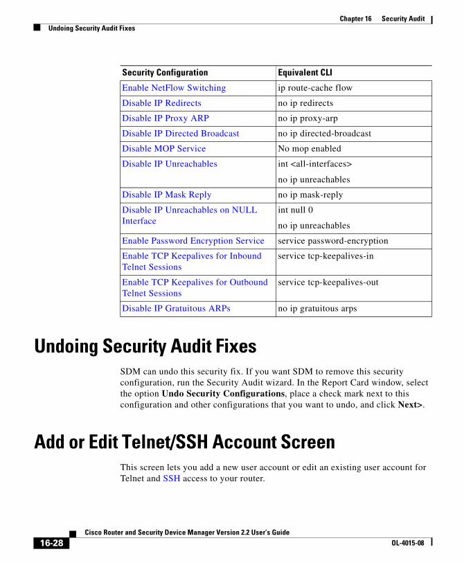
Chapter 16 Security AuditUndoing Security Audit Fixes
Undoing Security Audit FixesSDM can undo this security fix. If you want SDM to remove this security configuration, run the Security Audit wizard. In the Report Card window, select the option Undo Security Configurations, place a check mark next to this configuration and other configurations that you want to undo, and click Next>.
Add or Edit Telnet/SSH Account ScreenThis screen lets you add a new user account or edit an existing user account for Telnet and SSH access to your router.
Enable NetFlow Switching ip route-cache flow
Disable IP Redirects no ip redirects
Disable IP Proxy ARP no ip proxy-arp
Disable IP Directed Broadcast no ip directed-broadcast
Disable MOP Service No mop enabled
Disable IP Unreachables int <all-interfaces>
no ip unreachables
Disable IP Mask Reply no ip mask-reply
Disable IP Unreachables on NULL Interface
int null 0
no ip unreachables
Enable Password Encryption Service service password-encryption
Enable TCP Keepalives for Inbound Telnet Sessions
service tcp-keepalives-in
Enable TCP Keepalives for Outbound Telnet Sessions
service tcp-keepalives-out
Disable IP Gratuitous ARPs no ip gratuitous arps
Security Configuration Equivalent CLI
16-28Cisco Router and Security Device Manager Version 2.2 User’s Guide
OL-4015-08

Chapter 16 Security AuditConfigure User Accounts for Telnet/SSH Page
User Name
Enter the username for the new account in this field.
Password
Enter the password for the new account in this field.
Confirm Password
Reenter the new account password in this field for confirmation. The entry in this field must match the entry in the password field.
Configure User Accounts for Telnet/SSH PageThis screen lets you manage the user accounts that have Telnet or Secure Shell (SSH) access to your router. The table in this screen shows each Telnet user account, listing the account username and displaying asterisks to represent the account password. Note that this screen appears only if you have not already configured any user accounts; therefore, the table on this screen is always empty when it is initially displayed.
Enable Authorization for Telnet Check Box
Check this box to enable Telnet and SSH access to your router. Clear this box to disable Telnet and SSH access to your router.
Add... Button
Click this button to display the Add a User Account screen, letting you add an account by assigning the account a username and password.
Edit... Button
Click a user account in the table to select it, and click this button to display the Edit a User Account screen, letting you edit the username and password of the selected account.
16-29Cisco Router and Security Device Manager Version 2.2 User’s Guide
OL-4015-08
Chapter 16 Security AuditEnable Secret and Banner Page
Delete Button
Click a user account in the table to select it, and click this button to delete the selected account.
Enable Secret and Banner PageThis screen lets you enter a new enable secret and a text banner for the router.
The enable secret is an encrypted password that provides administrator-level access to all functions of the router. It is vital that the secret be secure and difficult to crack. Your secret must be a minimum of six characters long, and it is recommended that you include both alphabetic and numeric characters and that you do not use a word that can be found in a dictionary, or that might be personal information about yourself that someone might be able to guess.
The text banner will be displayed whenever anyone connects to your router using Telnet or SSH. The text banner is an important security consideration because it is a method of notifying unauthorized individuals that access to your router is prohibited. in some jurisdictions, this is a requirement for civil and/or criminal prosecution.
New Password
Enter the new enable secret in this field.
Re-enter New Password
Re-enter the new enable secret in this field for verification.
Login Banner
Enter the text banner that you want configured on your router.
16-30Cisco Router and Security Device Manager Version 2.2 User’s Guide
OL-4015-08

Chapter 16 Security AuditLogging Page
Logging PageThis screen lets you configure the router log by creating a list of syslog servers where log messages will be forwarded, and by setting the logging level, which determines the minimum severity a log message must have in order for it to be captured.
IP Address/Hostname Table
This table displays a list of hosts to where the router log messages will be forwarded. These hosts should be syslog servers that can trap and manage the router log messages.
Add... Button
Click this button to display the IP Address/Host Name screen, letting you add a syslog server to the list by entering either its IP address or host name.
Edit... Button
Click a syslog server in the table to select it, and click this button to display the IP Address/Host Name screen, letting you edit the IP address or host name of the selected syslog server.
Delete Button
Click a syslog server in the table to select it, and click this button to delete the selected syslog server from the table.
Set logging level Field
In this field, select the minimum severity level that a router log message must have in order for it to be trapped and forwarded to the syslog server(s) in the table on this screen. A log message severity level is shown as a number from 1 through 7, with lower numbers indicating more severe events. The descriptions of each of the severity levels are as follows:
– 0 - emergencies
System unusable
– 1- alerts
16-31Cisco Router and Security Device Manager Version 2.2 User’s Guide
OL-4015-08

Chapter 16 Security AuditLogging Page
Immediate action needed
– 2 - critical
Critical conditions
– 3 - errors
Error conditions
– 4 - warnings
Warning conditions
– 5 - notifications
Normal but significant condition
– 6 - informational
Informational messages only
– 7 - debugging
Debugging messages
16-32Cisco Router and Security Device Manager Version 2.2 User’s Guide
OL-4015-08

Cisco Router and Security DeOL-4015-08
C H A P T E R17
RoutingThe Routing window displays the configured static routes and Routing Internet Protocol, (RIP), Open Shortest Path First (OSPF), and Extended Interior Gateway Routing Protocol (EIGRP) configured routes. From this window, you can review the routes, add new routes, edit existing routes, and delete routes.
Note Static and dynamic routes configured for GRE over IPSec tunnels will appear in this window. If you delete a routing entry that is used for GRE over IPSec tunneling in this window, that route will no longer be available to the tunnel.
Static Routing
Destination Network
This is the network that the static route provides a path to.
Forwarding
This is the interface or IP address through which packets must be sent to reach the destination network.
Optional
This area shows whether a distance metric has been entered, and whether or not the route has been designated as a permanent route.
17-1vice Manager Version 2.2 User’s Guide

Chapter 17 Routing
What Do You Want To Do?
Note • If SDM detects a previously configured static route entry that has the next hop interface configured as the “Null” interface, then the static route entry will be read-only.
• If SDM detects a previously configured static route entry with “tag” or “name” options, that entry will be read-only.
• If you are configuring a Cisco 7000 router, and the interface used for a next hop is unsupported, that route will be marked as read only.
• Read-only entries cannot be edited or deleted using SDM.
Dynamic Routing
This portion of the window allows you to configure RIP, OSPF, and EIGRP dynamic routes.
Item Name
If no dynamic routes have been configured, this column contains the text RIP, OSPF, and EIGRP. When one or more routes have been configured, this column contains the parameter names for the type of routing configured.
If you want to: Do this:
Add a static route. Click Add, and create the static route in the Add a Static Route window.
Edit a static route. Select the static route, and click Edit. Edit the route information in the IP Static Route window.
When a route has been configured that SDM does not support, the Edit button is disabled.
Delete a static route. Select the static route, and click Delete. Then, confirm the deletion in the warning window.
Delete all static routes.
Click Delete All. Then, confirm the deletion in the warning window.
17-2Cisco Router and Security Device Manager Version 2.2 User’s Guide
OL-4015-08

Chapter 17 RoutingAdd or Edit IP Static Route
Item Value
This column contains the text “Enabled,” and configuration values when a routing type has been configured. It contains the text “Disabled” when a routing protocol has not been configured.
What Do You Want To Do?
Add or Edit IP Static RouteUse this window to add or edit a static route.
Destination Network
Enter the destination network address information in these fields.
Routing Protocol Configuration Parameters
RIP RIP Version, Network, Passive Interface
OSPF Process ID
EIGRP Autonomous System Number
If you want to: Do this:
Configure an RIP route. Select the RIP tab and click Edit. Then, configure the route in the RIP Dynamic Route window.
Configure an OSPF route. Select the OSPF tab and click Edit. Then, configure the route in the displayed window.
Configure an EIGRP route. Select the EIGRP tab and click Edit. Then, configure the route in the displayed window.
17-3Cisco Router and Security Device Manager Version 2.2 User’s Guide
OL-4015-08

Chapter 17 RoutingAdd or Edit IP Static Route
Prefix
Enter the IP address of the destination network. For more information, refer to Available Interface Configurations.
Prefix Mask
Enter the destination address subnet mask.
Make this the default route
Check this box to make this the default route for this router. A default route forwards all the unknown outbound packets through this route.
Forwarding
Specify how to forward data to the destination network.
Interface
Click Interface if you want to select the interface of the router that forwards the packet to the remote network.
IP Address
Click IP Address if you want to enter the IP Address of the next hop router that receives and forwards the packet to the remote network.
Optional
You can optionally provide a distance metric for this route, and designate it as a permanent route.
Distance Metric for this route
Enter the metric value that has to be entered in the routing table. Valid values are 1 through 255.
Permanent Route
Check this box to make this static route entry a permanent route. Permanent routes are not deleted even if the interface is shut down or the router is unable to communicate with the next router.
17-4Cisco Router and Security Device Manager Version 2.2 User’s Guide
OL-4015-08

Chapter 17 RoutingAdd or Edit an RIP Route
Add or Edit an RIP RouteUse this window to add or edit a Routing Internet Protocol (RIP) route.
RIP Version
The values are RIP version 1, RIP version 2, and Default. Select the version supported by the Cisco IOS image that the router is running. When you select version 1, the router sends version 1 RIP packets and can receive version 1 packets. When you select version 2, the router sends version 2 RIP packets and can receive version 2 packets. When you select Default, the router sends version 1 packets, and can receive both version 1 and version 2 RIP packets.
IP Network List
Enter the networks on which you want to enable RIP. Click Add to add a network. Click Delete to delete a network from the list.
Available Interface List
The available interfaces are shown in this list.
Make Interface Passive
Check the box next to the interface if you do not want it to send updates to its neighbor. The interface will still receive routing updates, however.
Add or Edit an OSPF RouteUse this window to add or edit an Open Shortest Path First (OSPF) route.
OSPF Process ID
This field is editable when OSPF is first enabled; it is disabled once OSPF routing has been enabled. The process ID identifies the router’s OSPF routing process to other routers.
17-5Cisco Router and Security Device Manager Version 2.2 User’s Guide
OL-4015-08
Chapter 17 RoutingAdd or Edit an OSPF Route
IP Network List
Enter the networks that you want to create routes to. Click Add to add a network. Click Delete to delete a network from the list.
Network
The address of the destination network for this route. For more information, refer to Available Interface Configurations.
Mask
The subnet mask used on that network.
Area
The OSPF area number for that network. Each router in a particular OSPF area maintains a topological database for that area.
Note If SDM detects previously configured OSPF routing that includes “area” commands, then the IP Network List table will be read-only and cannot be edited.
Available Interface List
The available interfaces are shown in this list.
Make Interface Passive
Check the box next to the interface if you do not want it to send updates to its neighbor. The interface will still receive routing updates, however.
Add
Click Add to provide an IP address, network mask, and area number in the IP address window.
Edit
Click Edit to edit the IP address, network mask, or area number in the IP address window.
17-6Cisco Router and Security Device Manager Version 2.2 User’s Guide
OL-4015-08
Chapter 17 RoutingAdd or Edit EIGRP Route
Add or Edit EIGRP RouteUse this window to add or delete an Extended IGRP (EIGRP) route.
Autonomous System Number
The autonomous system number is used to identify the router’s EIGRP routing process to other routers.
IP Network List
Enter the networks that you want to create routes to. Click Add to add a network. Click Delete to delete a network from the list.
Available Interface List
The available interfaces are shown in this list.
Make Interface Passive
Check the box next to the interface if you do not want it to send updates to its neighbor. The interface will neither send nor receive routing updates.
Caution When you make an interface passive, EIGRP suppresses the exchange of hello packets between routers, resulting in the loss of their neighbor relationship. This not only stops routing updates from being advertised, but also suppresses incoming routing updates.
Add
Click Add to add a destination network IP address to the Network list.
Delete
Select an IP address, and click Delete to remove an IP address from the Network list.
17-7Cisco Router and Security Device Manager Version 2.2 User’s Guide
OL-4015-08

Chapter 17 RoutingAdd or Edit EIGRP Route
17-8Cisco Router and Security Device Manager Version 2.2 User’s Guide
OL-4015-08

Cisco Router and Security DeOL-4015-08
C H A P T E R18
Network Address TranslationNetwork Address Translation (NAT) is a robust form of address translation that extends addressing capabilities by providing both static address translations and dynamic address translations. NAT allows a host that does not have a valid registered IP address to communicate with other hosts through the Internet. The hosts may be using private addresses or addresses assigned to another organization; in either case, NAT allows these addresses that are not Internet-ready to continue to be used but still allow communication with hosts across the Internet.
Network Address Translation WizardsYou can use a wizard to guide you in creating a Network Address Translation (NAT) rule. Choose one of the following wizards:
• Basic NAT
Choose the Basic NAT wizard if you want to connect your network to the outside, or the Internet, and your network has hosts but no servers. Look at the example diagram that appears to the right when you choose Basic NAT. If your network is made up only of PCs that require access to the Internet, choose Basic NAT and click the Launch button.
• Advanced NAT
Choose the Advanced NAT wizard if you want to connect your network to the outside, or the Internet, and your network has hosts and servers, and the servers must be accessible to outside hosts (hosts on the Internet). Look at the example diagram that appears to the right when you choose Advanced NAT.
18-1vice Manager Version 2.2 User’s Guide

Chapter 18 Network Address TranslationNetwork Address Translation Wizards
If your network has email servers, web servers, or other types of servers and you want them to accept connections from the Internet, choose Advanced NAT and click the Launch button.
Note If you do not want your servers to accept connections from the Internet, you can use the Basic NAT wizard.
Basic NAT Wizard: WelcomeThe Basic NAT welcome window shows how the wizard will guide you through configuring NAT for connecting one or more LANs, but no servers, to the Internet.
Basic NAT Wizard: Connection
Choose an Interface
From the drop down menu, choose the interface that connects to the Internet. This is the router’s WAN interface.
Choose Networks
The list of available networks shows the networks connected to your router. Choose which networks will share the WAN interface in the NAT configuration you set up. To choose a network, enable its checkbox in the list of available networks.
Note Do not choose a network connected to the WAN interface set up in this NAT configuration. Remove that network from the NAT configuration by clearing its checkbox.
The list shows the following information for each network:
• The IP address range allocated to the network
• The network’s LAN interface
• Any comments entered about the network
18-2Cisco Router and Security Device Manager Version 2.2 User’s Guide
OL-4015-08

Chapter 18 Network Address TranslationNetwork Address Translation Wizards
To remove a network from the NAT configuration, clear its checkbox.
Note If SDM detects a conflict between the NAT configuration and an existing VPN configuration for the WAN interface, it will inform you with a dialog box after you click Next.
SummaryThis window shows you the NAT configuration you created, and allows you to save the configuration. The summary will appear similar to the following:
Interface that is connected to the Internet or to your Internet service provider:
FastEthernet0/0
IP address ranges that share the Internet connection:108.1.1.0 to 108.1.1.25587.1.1.0 to 87.1.1.25512.1.1.0 to 12.1.1.25510.20.20.0 to 10.20.20.255
If you used the Advanced NAT wizard, you may also see additional information similar to the following:
NAT rules for servers:Translate 10.10.10.19 TCP port 6080 to IP address of interface
FastEthernet0/0 TCP port 80Translate 10.10.10.20 TCP port 25 to 194.23.8.1 TCP port 25
Advanced NAT Wizard: WelcomeThe Advanced NAT welcome window shows how the wizard will guide you through configuring NAT for connecting your LANs and servers to the Internet.
18-3Cisco Router and Security Device Manager Version 2.2 User’s Guide
OL-4015-08

Chapter 18 Network Address TranslationNetwork Address Translation Wizards
Advanced NAT Wizard: Connection
Choose an Interface
From the drop down menu, choose the interface that connects to the Internet. This is the router’s WAN interface.
Additional Public IP Addresses
Click Add to enter public IP addresses that you own. You will be able to assign these IP address to servers on your network that you want to make available to the Internet.
To delete an IP address from the list, select the IP address and click Delete.
Add IP Address
Enter a public IP address that you own. You will be able to assign this IP address to a server on your network that you want to make available to the Internet.
Advanced NAT Wizard: Networks
Choose Networks
The list of available networks shows the networks connected to your router. Choose which networks will share the WAN interface in the NAT configuration you set up. To choose a network, enable its checkbox in the list of available networks.
Note Do not choose a network connected to the WAN interface set up in this NAT configuration. Remove that network from the NAT configuration by clearing its checkbox.
The list shows the following information for each network:
• The IP address range allocated to the network
• The network’s LAN interface
18-4Cisco Router and Security Device Manager Version 2.2 User’s Guide
OL-4015-08
Chapter 18 Network Address TranslationNetwork Address Translation Wizards
• Any comments entered about the network
To remove a network from the NAT configuration, clear its checkbox.
To add a network not directly connected to your router to the list, click Add Networks.
Note If SDM does not allow you to place a checkmark next to a network for which you want to configure a NAT rule, the interface associated with the network has already been designated as a NAT interface. This status will be indicated by the word Designated in the Comments column. If you want to configure a NAT rule for that interface, exit the wizard, click the Edit NAT tab, click Designate NAT Interfaces, and uncheck the interface. Then return to the wizard and configure the NAT rule.
Add Network
You can add a network to the list of networks made available in the Advanced NAT wizard. You must have the network’s IP address and network mask. For more information, refer to IP Addresses and Subnet Masks.
IP Address
Enter the network’s IP address.
Subnet Mask
Enter the network’s subnet mask in this field, or select the number of subnet bits from the scrolling field on the right. The subnet mask tells the router which bits of the IP address designate the network address and which bits designate the host address.
Advanced NAT Wizard: Server Public IP AddressesThis window allows you to translate public IP addresses to the private IP addresses of internal servers which you want to make accessible from the Internet.
The list shows the private IP addresses and ports (if used) and the public IP addresses and ports (if used) to which they are translated.
18-5Cisco Router and Security Device Manager Version 2.2 User’s Guide
OL-4015-08

Chapter 18 Network Address TranslationNetwork Address Translation Wizards
To reorder the list based on the private IP addresses, click the column head Private IP Address. To reorder the list based on the public IP addresses, click the column head Public IP Address.
Add Button
To add a translation rule for a server, click Add.
Edit Button
To edit a translation rule for a server, select it in the list and click Edit.
Delete Button
To delete a translation rule, select it in the list and click Delete.
Add or Edit Address Translation Rule
In this window you can enter or edit the IP address translation information for a server.
Private IP Address
Enter the IP address that the server uses on your internal network. This is an IP address that cannot be used externally, on the Internet.
Public IP Address
From the drop-down menu, choose the public IP address to which the server’s private IP address will be translated. The IP addresses that appear in the drop-down menu include the IP address of the router’s WAN interface and any public IP addresses you own which were entered in the connections window (see Advanced NAT Wizard: Connection).
Show or Hide Advanced Button
Click the Show or Hide Advanced button to show or hide advanced options that let you specify more information about the server.
18-6Cisco Router and Security Device Manager Version 2.2 User’s Guide
OL-4015-08

Chapter 18 Network Address TranslationNetwork Address Translation Wizards
Type of Server
This field appears only if you choose to show advanced options with the Show or Hide Advanced button.
Choose one of the following server types from the drop-down menu:
• Web server
An HTTP host serving HTML and other WWW-oriented pages.
• Email server
An SMTP server for sending Internet mail.
• Other
The server is not a web or email server, but requires port translation to provide service.
If you do not choose a server type, all traffic intended for the public IP address you choose for the server will be routed to it, and no port translation will be done.
Original Port
Enter the port number used by the server to accept service requests from the internal network.
This field appears only if you choose to show advanced options with the Show or Hide Advanced button and you choose a server type.
Translated Port
Enter the port number used by the server to accept service requests from the Internet.
This field appears only if you choose to show advanced options with the Show or Hide Advanced button and you choose Other for server type.
Protocol
Choose TCP or UDP for the protocol used by the server with the original and translated ports.
This field appears only if you choose to show advanced options with the Show or Hide Advanced button and you choose Other for server type.
18-7Cisco Router and Security Device Manager Version 2.2 User’s Guide
OL-4015-08
Chapter 18 Network Address TranslationNetwork Address Translation Rules
Advanced NAT Wizard: VPN ConflictIf this Advanced NAT wizard window appears, SDM has detected a conflict between the NAT configuration and an existing VPN configuration for the WAN interface.
Choose to modify the NAT configuration to remove the conflict, or choose to not modify the NAT configuration. If you choose to not modify the NAT configuration, the conflict may cause your VPN connection to stop working.
View Details
Click the View Details button to see the proposed modifications to the NAT configuration to resolve the conflict.
Details
This window lists the changes SDM will make to the NAT configuration to resolve conflicts between NAT and VPN configured on the same interface.
Network Address Translation RulesThe Network Address Translation Rules window lets you view NAT rules, view address pools, and set translation timeouts. From this window you can also designate interfaces as inside or outside interfaces.
For more information on NAT, follow the link More About NAT.
Designate NAT Interfaces
Click to designate interfaces as inside or outside. NAT uses the Inside/Outside designations as reference points when interpreting translation rules. Inside interfaces are those interfaces connected to the private networks that the router is connected to. Outside interfaces connect to the WAN or to the Internet. The designated Inside and Outside interfaces are listed above the NAT rule list.
18-8Cisco Router and Security Device Manager Version 2.2 User’s Guide
OL-4015-08

Chapter 18 Network Address TranslationNetwork Address Translation Rules
Address Pools
Click this button to configure or edit address pools. Address pools are used with dynamic address translation. The router can dynamically assign addresses from the pool as they are needed. When an address is no longer needed, it is returned to the pool.
Translation Timeouts
When dynamic NAT is configured, translation entries have a timeout period after which they expire and are purged from the translation table. Click this button to configure the timeout values for NAT translation entries and other values.
Network Address Translation Rules
This area shows the designated inside and outside interfaces and the NAT rules that have been configured.
Inside Interfaces
The inside interfaces are the interfaces that connect to the private networks the router serves. NAT uses the Inside designation when interpreting a NAT translation rule. You can designate interfaces as inside by clicking Designate NAT interfaces.
Outside Interfaces
The outside interfaces are the router interfaces that connect to the WAN or the Internet. NAT uses the Outside designation when interpreting a NAT translation rule. You can designate interfaces as outside by clicking Designate NAT interfaces.
Original Address
This is the private address or set of addresses that is used on the LAN.
Translated Address
This is the legal address or range of addresses that is used on the Internet or the external network.
18-9Cisco Router and Security Device Manager Version 2.2 User’s Guide
OL-4015-08

Chapter 18 Network Address TranslationNetwork Address Translation Rules
Rule Type
Rules are either static address translation rules or dynamic address translation rules.
Static address translation allows hosts with private addresses to access the Internet and to be publicly accessible from the Internet. It statically maps one private IP address to one public or global address. If you wanted to provide static translation to 10 private addresses, you would create a separate static rule for each address.
Dynamic address translation. There are two methods of dynamic addressing using NAT. One method maps multiple private addresses to a single public address and the port numbers of host sessions to determine which host to route returning traffic to. The second method uses named address pools. These address pools contain public addresses. When a host with a private address needs to establish communication outside the LAN, it is given a public address from this pool. When the host no longer needs it, the address is returned to the pool.
Clone selected entry on Add
If you want to use an existing rule as the basis for a new rule that you want to create, select the rule and check this box. When you click Add, the addresses in the rule you selected appear in the Add Address Translation Rule window. You can edit these addresses to get the ones you need for the new rule instead of typing the entire address into each field.
What do you want to do?
If you want to: Do this:
Designate the inside and outside interfaces.
You must designate at least one inside interface and one outside interface in order for the router to perform NAT.
Click Designate NAT interfaces, and designate interfaces as inside or outside in the NAT Interface Setting window. Interfaces can also be designated as inside or outside interfaces in the Interfaces and Connections window.
Add, edit, or delete an address pool.
Dynamic rules can use address pools to assign addresses to devices as they are needed.
Click Address Pools, and configure address pool information in the dialog box.
18-10Cisco Router and Security Device Manager Version 2.2 User’s Guide
OL-4015-08

Chapter 18 Network Address TranslationNetwork Address Translation Rules
Make translation timeout settings. Click Translation Timeouts, and make settings in the Translation Timeouts window.
Add a NAT rule. Click Add, and create the NAT rule in the Add Address Translation Rule window.
If you want to use an existing NAT rule as a template for the new rule, select the rule, click Clone selected entry on Add, and then click Add.
Edit a NAT rule. Select the NAT rule that you want to edit, click Edit, and edit the rule in the Edit Address Translation Rule window.
Delete a NAT rule. Select the NAT rule that you want to delete, and click Delete. You must confirm deletion of the rule in the Warning box displayed.
View and/or edit route maps.
If virtual private network (VPN) connections are configured on the router, the local IP addresses in the VPN must be protected from NAT translations. When both VPN and NAT are configured, Cisco Router and Security Device Manager (SDM) creates route maps to protect IP addresses in a VPN from being translated. Additionally, route maps may be configured using the command-line interface (CLI). You can view configured route maps and edit the access rule they use.
Click View Route MAP.
Find out how to perform related configuration tasks.
Refer to one of the following procedures:
• How Do I Configure NAT Passthrough for a VPN?
• How Do I Configure NAT on an Unsupported Interface?
• How Do I Configure NAT Passthrough for a Firewall?
If you want to: Do this:
18-11Cisco Router and Security Device Manager Version 2.2 User’s Guide
OL-4015-08

Chapter 18 Network Address TranslationNetwork Address Translation Rules
Note There are many conditions that cause previously-configured NAT rules to appear as read-only in the Network Address Translation Rules list, causing the rule to not be editable. For more information, see the help topic Reasons that SDM Cannot Edit a NAT Rule.
Designate NAT InterfacesUse this window to designate the inside and outside interfaces that you want to use in NAT translations. NAT uses the Inside and Outside designations when interpreting translation rules, because translations are performed from inside to outside, or from outside to inside.
Once designated, these interfaces will be used in all NAT translation rules. The designated interfaces appear above the Translation Rules list in the main NAT window.
Interface
All router interfaces are listed in this column.
Inside (trusted)
Check to designate an interface as an inside interface. Inside interfaces typically connect to a LAN that the router serves.
Outside (untrusted)
Check to designate an interface as an outside interface. Outside interfaces typically connect to your organization’s WAN or to the Internet.
Translation Timeout SettingsWhen you configure dynamic NAT translation rules, translation entries have a timeout period after which they expire and are purged from the translation table. Set the timeout values for various translations in this window.
18-12Cisco Router and Security Device Manager Version 2.2 User’s Guide
OL-4015-08

Chapter 18 Network Address TranslationNetwork Address Translation Rules
DNS Timeout
Enter the number of seconds after which connections to DNS servers time out.
ICMP Timeout
Enter the timeout value for Internet Control Message Protocol (ICMP) flows. The default is 60 seconds.
PPTP Timeout
Enter the timeout value for NAT Point-to-Point Tunneling Protocol (PPTP) flows. The default is 86400 seconds (24 hours).
Dynamic NAT Timeout
Enter the maximum number of seconds that dynamic NAT translations should live.
Max Number of NAT Entries
Enter the maximum number of NAT entries in the translation table.
UDP flow timeouts
Enter the number of seconds that translations for User Datagram Protocol (UDP) flows should live. The default is 300 seconds (5 minutes).
TCP flow timeouts
Enter the number of seconds that translations for Transmission Control Protocol (TCP) flows should live. The default is 86400 seconds (24 hours).
Reset Button
Clicking this button resets translation and timeout parameters to their default values.
18-13Cisco Router and Security Device Manager Version 2.2 User’s Guide
OL-4015-08

Chapter 18 Network Address TranslationNetwork Address Translation Rules
Edit Route MapWhen VPNs and NAT are both configured on a router, packets that would normally meet the criteria for an IPSec rule will not do so if NAT translates their IP addresses. In this case, NAT translation will cause packets to be sent without being encrypted. SDM may create route maps to prevent NAT from translating IP addresses that you want to be preserved.
Although SDM only creates route maps to limit the action of NAT, route maps can be used for other purposes as well. If route maps have been created using the CLI, they will be visible in this window as well.
Name
The name of this route map.
Route map entries
This box lists the route map entries.
Name
The name of the route map entry.
Seq No.
The sequence number of the route map.
Action
Route maps created by SDM are configured with the permit keyword. If this field contains the value deny, the route map was created using the CLI.
Access Lists
The access lists that specify the traffic to which this route map applies.
To edit a route map entry:
Select the entry, click Edit, and edit the entry in the Edit Route Map Entry window.
18-14Cisco Router and Security Device Manager Version 2.2 User’s Guide
OL-4015-08
Chapter 18 Network Address TranslationNetwork Address Translation Rules
Edit Route Map Entry
Use this window to edit the access list specified in a route map entry.
Name
A read-only field containing the name of the route map entry.
Seq No.
A read-only field containing the sequence number for the route map. When SDM creates a route map, it automatically assigns it a sequence number.
Action
Either permit or deny. Route maps created by SDM are configured with the permit keyword. If this field contains the value deny, the route map was created using the CLI.
Access Lists
This area shows the access lists associated with this entry. The route map uses these access lists to determine which traffic to protect from NAT translation.
To edit an access list in a route map entry:
Select the access list, and click Edit. Then, edit the access list in the windows displayed.
Address PoolsThe Address Pools window shows the configured address pools that can be used in dynamic NAT translation.
Pool Name
This field contains the name of the address pool. Use this name to refer to the pool when configuring a dynamic NAT rule.
18-15Cisco Router and Security Device Manager Version 2.2 User’s Guide
OL-4015-08
Chapter 18 Network Address TranslationNetwork Address Translation Rules
Address
This field contains the IP address range in the pool. Devices whose IP addresses match the access rule specified in the Add Address Translation rule window will be given private IP addresses from this pool.
What do you want to do?
Note If SDM detects a previously-configured NAT address pool that uses the “type” keyword, that address pool will be read-only and cannot be edited.
Add or Edit Address Pool
Use this window to specify an address pool for dynamic address translation, an address for Port Address Translation (PAT), or a TCP load balancing rotary pool.
Pool Name
Enter the name of the address pool.
If you want to: Do this:
Add an address pool to the router’s configuration.
Click Add, and configure the pool in the Add Address Pool window.
If you want to use an existing pool as a template for the new pool, select the existing pool, check Clone selected entry on Add, and click Add.
Edit an existing address pool. Select the pool entry, click Edit, and edit the pool configuration in the Edit Address Pool window.
Delete an address pool. Select the pool entry, click Delete, and confirm deletion in the Warning box displayed.
18-16Cisco Router and Security Device Manager Version 2.2 User’s Guide
OL-4015-08
Chapter 18 Network Address TranslationNetwork Address Translation Rules
Port Address Translation (PAT)
There may be times when most of the addresses in the pool have been assigned, and the IP address pool is nearly depleted. When this occurs, PAT can be used with a single IP address to satisfy additional requests for IP addresses. Check this box if you want the router to use PAT when the address pool is close to depletion.
IP Address
Enter the lowest numbered IP address in the range in the left field; enter the highest numbered IP address in the range in the right field. For more information, refer to Available Interface Configurations.
Network Mask
Enter the subnet mask or the number of network bits that specify how many bits in the IP addresses are network bits.
Add or Edit Static Address Translation Rule: Inside to OutsideUse this help topic when you have chosen direction From Inside to Outside in the Add or the Edit Static Address Translation Rule window.
Use this window to add or edit a static address translation rule. If you are editing a rule, the rule type, static or dynamic, and the direction are disabled. If you need to change these settings, delete the rule, and recreate it using the settings you want.
There are two types of static address translations using NAT, simple static and extended static.
Note If you create a NAT rule that would translate addresses of devices that are part of a VPN, SDM will prompt you to allow it to create a route map that protects those addresses from being translated by NAT. If NAT is allowed to translate addresses of devices on a VPN, their translated addresses will not match the IPSec rule used in the IPSec policy, and traffic will be sent unencrypted. You can view route maps created by SDM or created using the CLI by clicking the View Route Maps button in the NAT window.
18-17Cisco Router and Security Device Manager Version 2.2 User’s Guide
OL-4015-08
Chapter 18 Network Address TranslationNetwork Address Translation Rules
Direction
This help topic describes how to use the Add Address Translation Rule fields when From inside to outside is selected.
From inside to outside
Select this option if you want to translate private addresses on the LAN to legal addresses on the Internet or on your organization’s intranet. You may want to select this option if you use private addresses on your LAN that are not globally unique on the Internet.
Translate from Interface
This area shows the interfaces from which packets needing address translation may arrive. It provides fields for you to specify the IP address of a single host, or a network address and subnet mask that represent the hosts on a network.
Inside Interface(s)
If you chose From inside to outside for Direction, this area lists the designated inside interfaces.
Note If this area contains no interface names, close the Add Address Translation Rule window, click Designate NAT interfaces in the NAT window, and designate the router interfaces as inside or outside. Then return to this window and configure the NAT rule.
IP Address
Do one of the following:
• If you want to create a one-to-one static mapping between the address of a single host and a translated address, known as the inside global address, enter the IP address for that host. Do not enter a subnet mask in the Network Mask field.
• If you want to create n-to-n mappings between the private addresses in a subnet to corresponding inside global addresses, enter any valid address from the subnet whose addresses you want translated, and enter a network mask in the next field.
18-18Cisco Router and Security Device Manager Version 2.2 User’s Guide
OL-4015-08
Chapter 18 Network Address TranslationNetwork Address Translation Rules
Network Mask
If you want SDM to translate the addresses of a subnet, enter the mask for that subnet. SDM determines the network/subnet number and the set of addresses needing translation from the IP address and mask that you supply.
Translate to Interface
This area shows the interfaces out of which packets with translated addresses may exit the router. It also provides fields in which you can specify the translated address and other information.
Outside Interface(s)
If you chose From inside to outside for Direction, this area contains the designated outside interfaces.
Type
• Select IP Address if you want the address to be translated to the address defined in the IP Addresss field.
• Select Interface if you want the Translate from... address to use the address of an interface on the router. The Translate from... address will be translated to the IP address assigned to the interface that you specify in the interface field.
Interface
This field is enabled if Interface is selected in the Type field. This field lists the interfaces on the router. Select the interface whose IP address you want the local inside address translated to.
Note If Interface is selected in the Type field, only redirect port translations are supported.
IP Address
This field is enabled if you selected IP Address in the Type field. Do one of the following:
• If you are creating a one-to-one mapping between a single inside local address and a single inside global address, enter the inside global address in this field.
18-19Cisco Router and Security Device Manager Version 2.2 User’s Guide
OL-4015-08
Chapter 18 Network Address TranslationNetwork Address Translation Rules
• If you are mapping the inside local addresses of a subnet to the corresponding inside global addresses, enter any IP address that you want to use in the translation in this field. The network mask entered in the Translate from... Interface area will be used to calculate the remaining inside global addresses.
Note If you do not enter a network mask in the Translate from Interface area, SDM will perform only one translation.
Redirect Port
Check this box if you want to include port information for the inside device in the translation. This enables you to use the same public IP address for multiple devices, as long as the port specified for each device is different. You must create an entry for each port mapping that you want to make for this “Translated to” address.
Click TCP if this is a TCP port number; click UDP if it is a UDP port number.
Original Port. Enter the port number on the inside device.
Translated Port. Enter the port number that the router is to use for this translation.
Configuration Scenarios
Click Static Address Translation Scenarios for examples that illustrate how the fields in this window are used.
Add or Edit Static Address Translation Rule: Outside to InsideUse this help topic when you have chosen direction From Outside to Inside in the Add or the Edit Static Address Translation Rule window.
Use this window to add or edit a static address translation rule. If you are editing a rule then the rule type, static or dynamic, and the direction are disabled. If you need to change these settings, delete the rule, and recreate it using the settings you want.
There are two types of static address translations using NAT, simple static and extended static.
18-20Cisco Router and Security Device Manager Version 2.2 User’s Guide
OL-4015-08

Chapter 18 Network Address TranslationNetwork Address Translation Rules
Note If you create a NAT rule that would translate addresses of devices that are part of a VPN, SDM will prompt you to allow it to create a route map that protects those addresses from being translated by NAT. If NAT is allowed to translate addresses of devices on a VPN, their translated addresses will not match the IPSec rule used in the IPSec policy, and traffic will be sent unencrypted. You can view route maps created by SDM or created using the CLI by clicking the View Route Maps button in the NAT window.
Direction
Select the traffic direction that this rule applies to.
From outside to inside
Select this option if you want to translate incoming addresses to addresses that will be valid on your LAN. One situation in which you may want to do this is when you are merging networks and must make one set of incoming addresses compatible with an existing set on the LAN the router serves.
This help topic describes how the remaining fields are used when From outside to inside is chosen.
Translate from Interface
This area shows the interfaces from which packets needing address translation may arrive. It provides fields for you to specify the IP address of a single host, or a network address and subnet mask that represent the hosts on a network.
Outside Interfaces
If you choose From outside to inside, this area contains the designated outside interfaces.
Note If this area contains no interface names, close the Add Address Translation Rule window, click Designate NAT interfaces in the NAT window, and designate the router interfaces as inside or outside. Then return to this window and configure the NAT rule.
18-21Cisco Router and Security Device Manager Version 2.2 User’s Guide
OL-4015-08
Chapter 18 Network Address TranslationNetwork Address Translation Rules
IP Address
Do one of the following:
• If you want to create a one-to-one static mapping between the outside global address of a single remote host and a translated address, known as the outside local address, enter the IP address for the remote host.
• If you want to create n-to-n mappings between the addresses in a remote subnet to corresponding outside local addresses, enter any valid address from the subnet whose addresses you want translated, and enter a network mask in the next field.
Network Mask
If you want SDM to translate the addresses in a remote subnet, enter the mask for that subnet. SDM determines the network/subnet number and the set of addresses needing translation from the IP address and mask that you supply.
Translate to Interface
This area shows the interfaces out of which packets with translated addresses may exit the router. It also provides fields in which you can specify the translated address and other information.
Inside Interface(s)
If you choose From outside to inside, this area contains the designated inside interfaces.
IP Address
Do one of the following:
• If you are creating a one-to-one mapping between a single outside global address and a single outside local address, enter the outside local address in this field.
• If you are mapping the outside global addresses of a remote subnet to the corresponding outside local addresses, enter any IP address that you want to use in the translation in this field. The network mask entered in the Translate from Interface area will be used to calculate the remaining outside local addresses.
18-22Cisco Router and Security Device Manager Version 2.2 User’s Guide
OL-4015-08
Chapter 18 Network Address TranslationNetwork Address Translation Rules
Note If you do not enter a network mask in the Translate from Interface area, SDM will perform only one translation.
Redirect Port
Check this box if you want to include port information for the outside device in the translation. This enables you to use extended static translation and to use the same public IP address for multiple devices, as long as the port specified for each device is different.
Click TCP if this is a TCP port number; click UDP if it is a UDP port number.
Original Port. Enter the port number on the outside device.
Translated Port. Enter the port number that the router is to use for this translation.
Configuration Scenarios
Click Static Address Translation Scenarios for examples that illustrate how the fields in this window are used.
Add or Edit Dynamic Address Translation Rule: Inside to OutsideUse this help topic when you have chosen direction From Inside to Outside in the Add or the Edit Dynamic Address Translation Rule window.
Add or edit an address translation rule in this window. If you are editing a rule, the rule type, static or dynamic, and the direction are disabled. If you need to change these settings, delete the rule, and recreate it using the settings you want.
A dynamic address translation rule dynamically maps hosts to addresses, using addresses included in a pool of addresses that are globally unique in the destination network. The pool is defined by specifying a range of addresses and giving the range a unique name. The configured router uses the available addresses in the pool (those not used for static translations or for its own WAN IP address) for connections to the Internet or other outside network. When an address is no longer in use, it is returned to the address pool to be dynamically assigned to another device later.
18-23Cisco Router and Security Device Manager Version 2.2 User’s Guide
OL-4015-08

Chapter 18 Network Address TranslationNetwork Address Translation Rules
Note If you create a NAT rule that would translate addresses of devices that are part of a VPN, SDM will prompt you to allow it to create a route map that protects those addresses from being translated by NAT. If NAT is allowed to translate addresses of devices on a VPN, their translated addresses will not match the IPSec rule used in the IPSec policy, and traffic will be sent unencrypted.
Direction
Select the traffic direction to which this rule applies.
From inside to outside
Select this option if you want to translate private addresses on the LAN to legal addresses on the Internet or on your organization’s intranet. You may want to select this option if you use private addresses on your LAN that are not globally unique on the Internet.
This help topic describes how the remaining fields are used when From inside to outside is chosen.
Translate from Interface
This area shows the interfaces from which packets needing address translation may arrive. It provides fields for you to specify the IP address of a single host, or a network address and subnet mask that represent the hosts on a network.
Inside Interface(s)
If you chose From inside to outside for Direction, this area contains the designated inside interfaces.
Note If this area contains no interface names, close the Add Address Translation Rule window, click Designate NAT interfaces in the NAT window, and designate the router interfaces as inside or outside. Then return to this window and configure the NAT rule.
18-24Cisco Router and Security Device Manager Version 2.2 User’s Guide
OL-4015-08

Chapter 18 Network Address TranslationNetwork Address Translation Rules
Access Rule...
Dynamic NAT translation rules use access rules to specify the addresses that need translation. If you select From inside to outside, these are the inside local addresses. Enter the name or number of the access rule that defines the addresses you want to translate. If you do not know the name or number, you can click on the ... button and select an existing access rule, or you can create a new access rule and select it.
Translate to Interface
This area shows the interfaces out of which packets with translated addresses may exit the router. It also provides fields for you to specify the translated address.
Outside Interface(s)
If you chose From inside to outside for Direction, this area contains the designated outside interfaces.
Type
Select Interface if you want the Translate from... addresses to use the address of an interface on the router. They will be translated to the address that you specify in the interface field, and PAT will be used to distinguish each host on the network. Select Address Pool if you want the addresses to be translated to addresses defined in a configured address pool.
Interface
If Interface is selected in the Type field, this field lists the interfaces on the router. Select the interface whose IP address you want the local inside addresses translated to. PAT will be used to distinguish each host on the network.
Address Pool
If Address Pool is selected in the Type field, you can enter the name of a configured address pool in this field, or you can click Address Pool to select or create an address pool.
Configuration Scenarios
Click Dynamic Address Translation Scenarios for examples that illustrate how the fields in this window are used.
18-25Cisco Router and Security Device Manager Version 2.2 User’s Guide
OL-4015-08
Chapter 18 Network Address TranslationNetwork Address Translation Rules
Add or Edit Dynamic Address Translation Rule: Outside to InsideUse this help topic when you have chosen direction From Outside to Inside in the Add or the Edit Dynamic Address Translation Rule window.
Add or edit an address translation rule in this window. If you are editing a rule, the rule type, static or dynamic, and the direction are disabled. If you need to change these settings, delete the rule, and recreate it using the settings you want.
A dynamic address translation rule dynamically maps hosts to addresses, using addresses included in a pool of addresses that are globally unique in the destination network. The pool is defined by specifying a range of addresses and giving the range a unique name. The configured router uses the available addresses in the pool (those not used for static translations or for its own WAN IP address) for connections to the Internet or other outside network. When an address is no longer in use, it is returned to the address pool to be dynamically assigned to another device later.
Note If you create a NAT rule that would translate addresses of devices that are part of a VPN, SDM will prompt you to allow it to create a route map that protects those addresses from being translated by NAT. If NAT is allowed to translate addresses of devices on a VPN, their translated addresses will not match the IPSec rule used in the IPSec policy, and traffic will be sent unencrypted.
Direction
Select the traffic direction to which this rule applies.
From outside to inside
Select this option if you want to translate incoming addresses to addresses that will be valid on your LAN. One situation in which you may want to do this is when you are merging networks and must make one set of incoming addresses compatible with an existing set on the LAN the router serves.
This help topic describes how the remaining fields are used when From outside to inside is chosen.
18-26Cisco Router and Security Device Manager Version 2.2 User’s Guide
OL-4015-08

Chapter 18 Network Address TranslationNetwork Address Translation Rules
Translate from Interface
This area shows the interfaces from which packets needing address translation may arrive. It provides fields for you to specify the IP address of a single host, or a network address and subnet mask that represent the hosts on a network.
Outside Interfaces
If you chose From outside to inside, this area contains the designated outside interfaces.
Note If this area contains no interface names, close the Add Address Translation Rule window, click Designate NAT interfaces in the NAT window, and designate the router interfaces as inside or outside. Then return to this window and configure the NAT rule.
Access Rule...
Dynamic NAT translation rules use access rules to specify the addresses that need translation. If you select From outside to inside, these are the outside global addresses. Enter the name or number of the access rule that defines the addresses you want to translate. If you do not know the name or number, you can click the ... button and select an existing access rule, or you can create a new access rule and select it.
Translate to Interface
This area shows the interfaces out of which packets with translated addresses may exit the router. It also provides fields for you to specify the translated address.
Inside Interface(s)
If you choose From outside to inside, this area contains the designated inside interfaces.
18-27Cisco Router and Security Device Manager Version 2.2 User’s Guide
OL-4015-08

Chapter 18 Network Address TranslationHow Do I . . .
Type
Select Interface if you want the Translate from... addresses to use the address of an interface on the router. They will be translated to the address that you specify in the interface field, and PAT will be used to distinguish each host on the network. Select Address Pool if you want the addresses to be translated to addresses defined in a configured address pool.
Interface
If Interface is selected in the Type field, this field lists the interfaces on the router. Select the interface whose IP address you want the local inside addresses translated to. PAT will be used to distinguish each host on the network.
Address Pool
If Address Pool is selected in the Type field, you can enter the name of a configured address pool in this field, or you can click Address Pool to select or create an address pool.
Configuration Scenarios
Click Dynamic Address Translation Scenarios for examples that illustrate how the fields in this window are used.
How Do I . . .This section contains procedures for tasks that the wizard does not help you complete.
How Do I Configure NAT With One LAN and Multiple WANs?The NAT wizard allows you to configure a Network Address Translation (NAT) rule between one LAN interface on your router and one WAN interface. If you want to configure NAT between one LAN interface on your router and multiple WAN interfaces, first use the NAT wizard to configure an address translation rule between the LAN interface on your router and one WAN interface. Then follow the directions in one of the following sections:
• Add or Edit Static Address Translation Rule: Inside to Outside
18-28Cisco Router and Security Device Manager Version 2.2 User’s Guide
OL-4015-08

Chapter 18 Network Address TranslationHow Do I . . .
• Add or Edit Dynamic Address Translation Rule: Inside to Outside
Each time you add a new address translation rule using these directions, choose the same LAN interface and a new WAN interface. Repeat this procedure for all WAN interfaces that you want to configure with address translation rules.
18-29Cisco Router and Security Device Manager Version 2.2 User’s Guide
OL-4015-08

Chapter 18 Network Address TranslationHow Do I . . .
18-30Cisco Router and Security Device Manager Version 2.2 User’s Guide
OL-4015-08

Cisco Router and Security DeOL-4015-08
C H A P T E R19
Intrusion Prevention SystemIOS Intrusion Prevention System (IPS) allows you to manage intrusion prevention on routers that run an IOS image of version 12.3(8)T4 or later. IPS lets you monitor and prevents intrusions by comparing traffic against signatures of known threats and blocking the traffic when a threat is detected.
SDM lets you control the application of IPS on interfaces, import and edit signature definition files (SDFs) from Cisco.com, and configure the action that IPS is to take when a threat is detected.
Click on a drawer in the IPS cabinet to go to the screen you need.
IPS Tabs
Use the tabs at the top of the IPS window to go to the area where you need to work.
• Create IPS—Click to go to the IPS Rule wizard to create a new IPS rule.
• Edit IPS—Click to edit IPS rules and apply or remove them from interfaces.
• Import Signatures—Click to go to the Import Signatures wizard.
IPS Policies Drawer
Click to display the IPS Rules Configuration window where you can enable or disable IPS on an interface and view information about how IPS is applied. If you enable IPS on an interface you can optionally specify which traffic to examine for intrusion.
19-31vice Manager Version 2.2 User’s Guide

Chapter 19 Intrusion Prevention SystemIPS Rules
Global Settings Drawer
Click to display the Global Settings window where you make settings that affect the overall operation of IOS IPS.
SDEE Messages Drawer
Secure Device Event Exchange (SDEE) messages report on the progress of IPS initialization and operation. Click this node to display the SDEE Messages window, where you can review SDEE messages and filter them to display only error messages or only status messages.
Signatures Drawer
Click to display the Signatures window where you can manage signatures on the router.
NM CIDS Drawer
This node is visible if a Cisco Intrusion Detection System network module is installed in the router. Click to manage the IDS module.
IPS RulesAn IPS rule specifies an interface, the type and direction of traffic that IPS is to examine, and the location of the Signature Definition File (SDF) that the router uses.
Click the Create IPS Rule tab to use a wizard that guides you through rule configuration. Click the Edit IPS Rule tab to edit the IPS rules on the router.
Create IPS RuleThe Create IPS Rule wizard prompts you for the following information:
• The interface on which to apply the rule.
• Whether to apply IPS on inbound or on outbound traffic, or both.
• The access rule to use to select the type of traffic to examine.
19-32Cisco Router and Security Device Manager Version 2.2 User’s Guide
OL-4015-08

Chapter 19 Intrusion Prevention SystemIPS Rules
• The location of the Signature Definition File (SDF).
The use case scenario illustrates a configuration in which an IPS rule is used. Once you create the IPS rule and deliver the configuration to the router, you can modify the rule by clicking the Edit IPS Rule tab.
Click the Launch IPS Rule Wizard button to begin.
Welcome to the IPS Rule Configuration WizardThis window provides a summary of the tasks that you perform when you complete the IPS Rule wizard.
Click Next to begin configuring an IPS rule.
Select InterfacesSelect the interfaces on which you want to apply the IPS rule by specifying whether the rule is to be applied to inbound traffic or outbound traffic. If you check both the inbound and the outbound boxes the rule applies to traffic flowing in both directions.
For example, the following selections apply IPS on inbound traffic on the BRI 0 interface, and both traffic directions on the FastEthernet 0 interface.
SDF LocationIPS examines traffic by comparing it against signatures contained in a Signature Definition File (SDF). The SDF can be located in router flash or located on a remote system that the router can reach. You can specify multiple SDF locations so that if the router is not able to contact the first location, it can attempt to contact other locations until it obtains an SDF.
Interface Name Inbound Outbound
BRI 0 Check
FastEthernet 0 Check Check
19-33Cisco Router and Security Device Manager Version 2.2 User’s Guide
OL-4015-08
Chapter 19 Intrusion Prevention SystemIPS Rules
Use the Add, Delete, Move Up, and Move Down buttons to add, remove, and order a list of SDF locations that the router can attempt to contact to obtain an SDF. The router starts at the first entry, and works down the list until it obtains an SDF.
Cisco IOS images that support IOS IPS contain built-in signatures. If you check the box at the bottom of the window, the router will use the built-in signatures only if it cannot obtain an SDF from any location in the list.
IPS Rule Wizard SummaryThe Summary window displays the information that you have entered so that you can review it before delivering the changes to the router. Following is an example Summary window display:
Selected Interface: FastEthernet 0/1
IPS Scanning Direction: Both
Signature Definition File Location: flash//sdmips.sdf
Built-in enabled: yes
In this example, IPS is enabled on the FastEthernet 0/1 interface, and both inbound and outbound traffic is scanned. The SDF is named sdmips.sdf and is located in router flash. The router is configured to use the signature definitions built in to the Cisco IOS image that the router runs.
IPS Rules ConfigurationThis window displays the IPS status of all router interfaces, and allows you to enable and disable IPS on interfaces.
Interfaces
Use this list to filter the interfaces shown in the interface list area. Select between the following:
• All interfaces—All interfaces on the router.
• IPS interfaces—Interfaces on which IPS has been enabled.
19-34Cisco Router and Security Device Manager Version 2.2 User’s Guide
OL-4015-08
Chapter 19 Intrusion Prevention SystemIPS Rules
Enable Button
Click this button to enable IPS on the selected interface. You are able to specify the traffic directions to which IPS is to be applied, and the ACLs to use to define the type of traffic to examine. Enable or Edit IPS on an Interface has more information.
Edit Button
Click this button to edit the IPS characteristics applied to the selected interface.
Disable Button
Click this button to disable IPS on the selected interface. A context menu shows you the traffic directions on which IPS has been applied and you can select the direction on which you want to disable IPS. If you disable IPS on an interface on which it has been applied, SDM dissociates any IPS rules from the interface that they were applied to.
Disable All Button
Click this button to disable IPS on all interfaces on which it has been enabled. If you disable IPS on an interface on which it has been applied, SDM dissociates any IPS rules from the interfaces that they were applied to.
Interface Name
The name of the interface, for example Serial0/0, or FE0/1.
IP
IP Address
This column can contain the following types of IP addresses:
• The configured IP address of the interface.
• DHCP Client—The interface receives an IP address from a Dynamic Host Configuration Protocol (DHCP) server.
• Negotiated—The interface receives an IP address via negotiation with the remote device.
19-35Cisco Router and Security Device Manager Version 2.2 User’s Guide
OL-4015-08

Chapter 19 Intrusion Prevention SystemIPS Rules
• Unnumbered—The router will use one of a pool of IP addresses supplied by your service provider for your router, and for the devices on the LAN.
• Not Applicable—The interface type cannot be assigned an IP address.
Inbound IPS/Outbound IPS
• Enabled—IPS is enabled for this traffic direction.
• Disabled—IPS is disabled for this traffic direction.
VFR Status
Virtual Fragment Reassembly (VFR) status. Possible values:
• On—VFR is enabled
• Off—VFR is disabled
IPS cannot identify the contents of IP fragments nor can it gather port information from the fragment in order to match it with a signature. These inabilities allow the fragments to pass through the network without being examined or without dynamic access control list (ACL) creation.
VFR enables the Cisco IOS Firewall to create the appropriate dynamic ACLs, thereby, protecting the network from various fragmentation attacks.
Description
A description of the connection, if one has been added.
IPS Filter Details
If no filter has been applied to traffic, this area contains no entries. If a filter is applied, the name or number of the ACL is shown in parentheses.
Inbound/Outbound Filter Buttons
Click to view the entries of the filter applied to inbound or outbound traffic.
Field Descriptions
Action—Whether the traffic is permitted or denied
19-36Cisco Router and Security Device Manager Version 2.2 User’s Guide
OL-4015-08
Chapter 19 Intrusion Prevention SystemIPS Rules
Source/Destination—A network or host address, or any host or network.
Service—Type of service filtered. IP, TCP, UDP, IGMP, and ICMP services can be filtered.
Log—Whether or not denied traffic is logged.
Options—Options configured using the CLI.
Description—Any description provided.
Enable or Edit IPS on an InterfaceUse this window to select the interfaces on which you want to enable intrusion detection, and to select the IPS filters that you want to use to specify the traffic to be examined.
Both/Inbound/Outbound
Use these buttons to specify whether you are going to enable IPS on both inbound and outbound traffic, only inbound traffic, or only outbound traffic.
Inbound Filter
(Optional) Enter the name or number of the access rule that specifies the inbound traffic to be examined. The ACL that you specify appears in the IPS Rules Configuration window when the interface with which it is associated is selected. If you need to browse for the access rule or create a new one, click the ... button.
Permit source traffic.
Deny source traffic.
19-37Cisco Router and Security Device Manager Version 2.2 User’s Guide
OL-4015-08

Chapter 19 Intrusion Prevention SystemImport Signatures
Outbound Filter
(Optional) Enter the name or number of the access rule that specifies the outbound traffic to be examined. The ACL that you specify appears in the IPS Rules Configuration window when the interface with which it is associated is selected. If you need to browse for the access rule or create a new one, click the ... button.
...Button
Use this button to specify a filter. Clicking this button displays a menu with the following option:
• Select an existing rule. Select a Rule has more information.
• Create a new rule. Add or Edit a Rule has more information.
• None (clear rule association). Use this option to remove a filter from a traffic direction to which it has been applied.
Enable fragment checking for this interface
(Enabled by default). Check if you want IOS firewall to check for IP fragments on this interface. See VFR Status for more information.
Enable fragment checking on other interfaces
If fragment checking is enabled for outbound traffic, the router must examine the inbound traffic that arrives on the interfaces that send outbound traffic to the interface being configured. Specify these interfaces below.
If the Inbound radio button is selected, this area does not appear.
Import SignaturesIPS prevents intrusion by comparing traffic against the signatures of known attacks. Cisco IOS images that support IPS have built-in signatures that IPS can use, but you can also have IPS import signatures for the router to use when examining traffic. Imported signatures are stored in a Signature Definition File (SDF).
Click the Import Signatures tab to import a Signature Definition File (SDF).
19-38Cisco Router and Security Device Manager Version 2.2 User’s Guide
OL-4015-08
Chapter 19 Intrusion Prevention SystemImport Signatures
Note Before you use the IPS Signature Import wizard, you must have saved the SDF that you intend to use to a directory on your PC.
Click the Edit Signatures tab to manage the signatures that IPS uses.
File SelectionThis window allows you to load a file from your router. Only DOSFS file systems can be viewed in this window.
The left side of window displays an expandible tree representing the directory system on your Cisco router flash memory and on USB flash devices connected to that router.
The right side of the window displays a list of the names of the files and directories found in the directory that is chosen in the left side of the window. It also shows the size of each file in bytes, and the date and time each file and directory was last modified.
You can choose a file to load in the list on the right side of the window. Below the list of files is a Filename field containing the full path of the currently chosen file. Files with the no-write icon next to their names cannot be chosen.
Filename
Click Filename to order the files and directories alphabetically based on name. Clicking Filename again will reverse the order.
Size
Click Size to order the files and directories by size. Directories always have a size of zero bytes, even if they are not empty. Clicking Size again will reverse the order.
Time Modified
Click Time Modified to order the files and directories based on modification date and time. Clicking Time Modified again will reverse the order.
19-39Cisco Router and Security Device Manager Version 2.2 User’s Guide
OL-4015-08
Chapter 19 Intrusion Prevention SystemImport Signatures
Welcome to the IPS Signature Import WizardThis window summarizes the tasks that you perform as you go through the IPS Signature Import wizard.
Click Next to begin.
Signature Definition File (SDF) and Signature SelectionClick Browse, and navigate to the SDF that you saved on your PC. When the path to the file is visible in the field, click Next to continue.
Signature FilterThe router may not have enough memory to use all signatures in the SDF. This screen allows you to build a set of criteria that IPS uses to filter the signatures so that the router only loads the ones appropriate for the network on which it is running.
In the Category list, select the type of criteria that you want to specify, such as OS, Service, or Attack. Then in the Value column, select the value for that category. The following example shows a list of three criteria. Click More to add a line. Click Fewer to remove the last line that you entered.
The read-only fields in the bottom part of the screens show the amount of memory required for the signatures that meet the criteria that you entered, and the amount of memory available on the router. If the amount of memory required to load the signatures that meet the criteria that you specified is greater than the available memory on the router, use the Fewer button to remove criteria.
You are able to view the signatures that match the criteria that you selected in the next screen.
Category Value
OS General
Service Telnet
Attack Adware/Spyware
19-40Cisco Router and Security Device Manager Version 2.2 User’s Guide
OL-4015-08
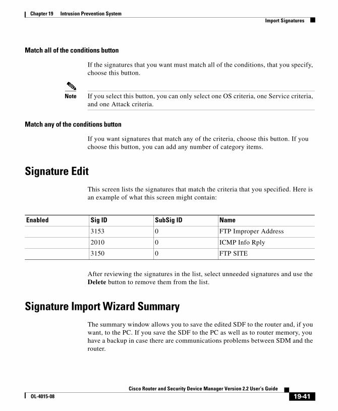
Chapter 19 Intrusion Prevention SystemImport Signatures
Match all of the conditions button
If the signatures that you want must match all of the conditions, that you specify, choose this button.
Note If you select this button, you can only select one OS criteria, one Service criteria, and one Attack criteria.
Match any of the conditions button
If you want signatures that match any of the criteria, choose this button. If you choose this button, you can add any number of category items.
Signature EditThis screen lists the signatures that match the criteria that you specified. Here is an example of what this screen might contain:
After reviewing the signatures in the list, select unneeded signatures and use the Delete button to remove them from the list.
Signature Import Wizard SummaryThe summary window allows you to save the edited SDF to the router and, if you want, to the PC. If you save the SDF to the PC as well as to router memory, you have a backup in case there are communications problems between SDM and the router.
Enabled Sig ID SubSig ID Name
3153 0 FTP Improper Address
2010 0 ICMP Info Rply
3150 0 FTP SITE
19-41Cisco Router and Security Device Manager Version 2.2 User’s Guide
OL-4015-08

Chapter 19 Intrusion Prevention SystemImport Signatures
SignaturesThis window lets you view the configured IPS signatures on the router. You can add customized signatures, or import signatures from Cisco.com-downloaded Signature Definition Files (SDF). You can also edit, delete, enable, and disable signatures.
IPS is shipped with an SDF that contains a number of signatures that your router can accommodate. To learn more about the SDF shipped with IPS, and how to have IPS use it, click IPS-Supplied Signature Definition Files.
Signature Tree
The signature tree enables you to filter the signature list on the right according to the type of signature that you want to view. First choose the branch for the general type of signature that you want to display. The signature list displays the configured signatures for the type that you chose. If a plus (+) sign appears to the left of the branch, there are subcategories that you can use to refine the filter. Click on the + sign to expand the branch and then select the signature subcategory that you want to display. If the signature list is empty, there are no configured signatures available for that type.
Example: If you want to display all attack signatures, click the Attack branch folder. If you want to see the subcategories that you can use to filter the display of attack signatures, click the + sign next to the Attack folder. If you want to see Denial of Service (DoS) signatures, click the DoS folder.
Total [n] New [n] Deleted [n]
This text gives you the count of new signatures and deleted signatures.
Select All
Click to select all signatures in the list.
Add
Click Add if you want to do any of the following:
• Clone—The clone option is enabled if one signature is selected that does not belong to a hardcoded engine. It is disabled if the signature uses one of the IOS hardcoded engines.
19-42Cisco Router and Security Device Manager Version 2.2 User’s Guide
OL-4015-08

Chapter 19 Intrusion Prevention SystemImport Signatures
Edit
Click the Edit button to edit the parameters of the selected signature.
Delete button
Click to mark the selected signature for deletion from the list. To view signatures you have deleted, click Details. For more information on the status and handling of these signatures, see Signatures marked for deletion.
Note You cannot delete built-in signatures such as TrendMicro OPACL signatures, as these signatures are part of the Cisco IOS image. If a built-in signature is highlighted, the Delete button is disabled.
Enable button
Click to enable the selected signature. An enabled signature is designated with a green checkmark. A signature that was disabled and then enabled has a yellow Wait icon in the ! column indicating that the change must be applied to the router.
Disable button
Click to disable the selected signature. A signature that is disabled is designated with a red icon. If the signature is disabled during the current session, a yellow Wait icon appears in the ! column indicating that the change must be applied to the router.
Import button
Click to import a signature definition file from the PC or from the router. When you have selected the file, IPS displays the signatures available in the file, and you can choose the ones that you want to import to the router. For more information about how to choose the signatures to import, see Import Signatures.
Note You can only import signatures from the router if the router has a DOS-based file system.
19-43Cisco Router and Security Device Manager Version 2.2 User’s Guide
OL-4015-08

Chapter 19 Intrusion Prevention SystemImport Signatures
SDFs are available from Cisco. Click the following URL to download an SDF from Cisco.com:
http://www.cisco.com/cgi-bin/tablebuild.pl/ios-sigup
Cisco maintains an alert center that provides information on emerging threats. See Cisco Intrusion Prevention Alert Center for more information
Summary/Details Button
Use this button to display or hide the signatures marked for deletion.
Signature List
The signature list displays the signatures retrieved from the router, and any signatures added from an SDF. The list can be filtered using the selection controls.
Enabled Enabled signatures are indicated with a green icon. If enabled, the actions specified when the signature is detected is carried out.
Disabled signatures are indicated with a red icon. If disabled, the actions are disabled and are not be carried out.
Alert (!) This column may contain the yellow Wait icon. This icon indicates new signatures that have not been delivered to the router or modified signatures that have not been delivered to the router.
Sig ID The numerical signature ID. For example, the sigID for ICMP Echo Reply is 2000.
SubSig ID The subsignature ID.
Name The name of the signature, for example ICMP Echo Reply.
Action The action to take when the signature is detected.
Filter An ACL associated with the corresponding signature.
Severity The severity level of the event. Severity levels are informational, low, medium, and high
Engine The engine to which the signature belongs.
19-44Cisco Router and Security Device Manager Version 2.2 User’s Guide
OL-4015-08

Chapter 19 Intrusion Prevention SystemImport Signatures
Icons
Right-click Context Menu
If you right-click a signature, SDM displays a context menu with the following options:
• Actions—Click to select the actions to be taken when the signature is matched. See Assign Actions for more information.
• Set Severity to—Click to set the severity level of a signature to: high, medium, low, or informational
• Restore Defaults—Click to restore the signature’s default values
• Remove Filter—Click to remove a filter applied to the signature.
• NSDB help (need CCO account)—Click to display help on the Network Security Data Base (NSDB).
Signatures marked for deletion
This area is visible when the Details button is clicked. It lists the signatures that you deleted from the Signature List. Signatures marked for deletion remain active in IPS configuration until you click Apply Changes. If you exit the Signatures window and disable IPS, the marked signatures will be deleted if IPS is re-enabled.
Undelete All button
Click this button if you want to restore all signatures in the signatures marked deleted list.
Undelete button
Click to restore selected signatures marked for deletion. When clicked the signatures are unmarked, and returned to the list of active signatures.
Signature is present in Router configuration and enabled.
Signature is present in router configuration but not active.
Signature status has changed in SDM, and awaits delivery to router.
19-45Cisco Router and Security Device Manager Version 2.2 User’s Guide
OL-4015-08

Chapter 19 Intrusion Prevention SystemImport Signatures
Apply Changes button
Click to deliver newly imported signatures, signature edits, and newly enabled or disabled signatures to the router. When the changes are applied, the yellow Wait icon is removed from the ! column.
Discard Changes button
Click to discard accumulated changes.
Assign ActionsThe window contains the actions that can be taken upon signature match. Available actions depend on the signature, but the most common actions are listed below:
• alarm—Generate an alarm.
• denyAttackerInline—creates an ACL that denies all traffic from the IP address that is considered the source of the attack by the IOS IPS system.
• denyFlowInline—creates an ACL that denies all traffic from the IP address that is considered the source of the attack that belongs to the 5-tuple (src ip, src port, dst ip, dst port and l4 protocol). denyFlowInline is more granular than denyAttackerInline.
• drop—Drop the packet.
• reset—Reset the connection.
Import SignaturesUse this window to import signatures from an SDF on your PC. The information in this window tells you which signatures are available from the SDF, and which of them are already deployed on your router.
Importing signatures is a two-step process. In Step 1, performed in the upper part of the window, you choose the signatures that you want to import. In Step 2, performed in the lower part of the window, you choose whether to merge these signatures with the signatures that are already configured on the router, or to replace the signatures on the router with the signatures that you are importing.
19-46Cisco Router and Security Device Manager Version 2.2 User’s Guide
OL-4015-08
Chapter 19 Intrusion Prevention SystemImport Signatures
Signature Tree
If you need a description of the signature tree, click this link: Signature Tree. You can use the signature tree in this window to assemble the signatures that you want to import, category by category.
For example, you may want to add signatures from the OS category, and from the Service category. You can do this by choosing the OS branch of the tree, and any branch from that part of the tree that you want, such as the UNIX branch or the Windows branch. When the types of signatures that you want to import are displayed, you can make your selections in the signature list area. Then, you can choose the Service branch, and choose any of the service signatures that you want.
Signature List Area
The signature list displays the signatures available in the SDF based on the criteria you selected in the signature tree. Review the signatures in this area and choose the ones that you want to import. If you want to import all the signatures in this area, click Select All.
The signature list area has these columns:
• Name—The name of the signature. For example, FTP Improper Address.
• Deployed—If the signature is already deployed on the router, this column contains Yes. If the signature is not deployed, the column contains No.
• Import—This column contains a checkbox for each signature. If you want to import the signature, check this box.
Merge
Choose this option to merge the signatures that you are importing with the signatures that are already configured on the router.
Replace
Choose this option to replace the signatures already configured on the router with the signatures that you are importing.
19-47Cisco Router and Security Device Manager Version 2.2 User’s Guide
OL-4015-08

Chapter 19 Intrusion Prevention SystemImport Signatures
Add, Edit, or Clone SignatureThis window contains fields and values described in the Field Definitions section. The fields vary depending on the signature. Therefore, this is not an exhaustive list of all the fields you might see.
Field Definitions
The following fields are found on the Add, Edit and Clone Signature screens.
• SIGID—Identifies the unique numerical value assigned to this signature. This value allows IPS to identify a particular signature.
• SigName—Identifies the name assigned to the signature.
• SubSig—Identifies the unique numerical value assigned to this sub-signature. A subSig ID is used to identify a more granular version of a broad signature.
• AlarmInterval—Special Handling for timed events. Use AlarmInterval Y with MinHits X for X alarms in Y second interval.
• AlarmSeverity —Severity reported in alarm for this signature.
• AlarmThrottle —Technique used for alarm firings.
• AlarmTraits—User-defined traits further describing this signature.
• ChokeThreshold—Threshold value of alarms-per-interval to auto-switch AlarmThrottle modes. If ChokeThreshold is defined IPS will automatically switch AlarmThrottle modes when a large volume of alarms is seen in the ThrottleInterval.
• Enabled—Identifies whether or not the signature is enabled. A signature must be enabled in order for IPS to protect against the traffic specified by the signature.
• EventAction—Identifies the actions IPS will take when this signature fires.
• FlipAddr—True if address (and ports) Source and Destination are swapped in the alarm message. False for no swap (normal).
• MinHits—Minimum number of signature hits before the alarm message is sent. This a limiter for firing the alarm only after X times of seeing the signature on the address key.
• SigComment—The comment of the signature.
19-48Cisco Router and Security Device Manager Version 2.2 User’s Guide
OL-4015-08

Chapter 19 Intrusion Prevention SystemImport Signatures
• SigVersion—Signature version.
• ThrottleInterval —Number of seconds defining an Alarm Throttle interval. This is used with the AlarmThrottle parameter to tune special alarm limiters.
• WantFrag—True if a fragment is desired. False if a fragment is not desired. Any for either.
Add or Edit a Signature LocationSpecify the location that IOS IPS should load an SDF from. To specify multiple SDF locations, open this dialog again and enter the information for another SDF.
Specify SDF on this router
Specify where the SDF is located on the router by choosing which part of router memory the file is in, for example disk0 or flash, and either choose or enter the filename in the File Name field.
Specify SDF using URL
If the SDF is located on a remote system, you can specify the URL at which it resides.
Protocol
Select the protocol the router should use to obtain the SDF, such as http, or https.
URL
Enter the Universal Resource Locator (URL) in the following form:
https://path-to-signature-file
The following URL is provided as an example of the format. It is not a valid URL to a signature file:
https://172.16.122.204/mysigs/vsensor.sdf
19-49Cisco Router and Security Device Manager Version 2.2 User’s Guide
OL-4015-08

Chapter 19 Intrusion Prevention SystemImport Signatures
Autosave
Check this option if you want the router to automatically save the SDF in the event of a router crash. This eliminates the need for you to reconfigure IPS with this SDF when the router comes back up.
Cisco Intrusion Prevention Alert CenterThe Cisco Intrusion Prevention Alert center provides information on emerging threats and links to the Cisco IPS signatures available to protect your network from them. The Cisco Intrusion Prevention Alert Center is available at this link:
http://www.cisco.com/pcgi-bin/front.x/ipsalerts/ipsalertsHome.pl
IPS-Supplied Signature Definition FilesTo ensure that the router has available as many signatures as its memory can accommodate, IPS is shipped with one of the following SDFs:
• 256MB.sdf—If the amount of RAM available is greater than 256 MB. 256MB.sdf contains 500 signatures.
• 128MB.sdf—If the amount of RAM available is between 128 MB and 256 MB. 128MB.sdf contains 300 signatures.
• attack-drop.sdf—If the amount of available RAM is 127 MB or less. attack-drop.sdf contains 82 signatures.
Note The router must be running a Cisco IOS image of release 12.3(14)T or later to be able to use all the available signature engines in 256MB.sdf and 128MB.sdf. If the router runs a Cisco IOS image of an earlier release, not all signature engines will be available.
To use an SDF in router memory, determine which SDF has been installed, and then configure IPS to use it. The procedures that follow show you how to do this.
19-50Cisco Router and Security Device Manager Version 2.2 User’s Guide
OL-4015-08

Chapter 19 Intrusion Prevention SystemGlobal Settings
Determine Which SDF File is in Memory
To determine which SDF file is in router memory, open a Telnet session to the router, and enter the show flash command. The output will be similar to the following:
System flash directory:File Length Name/status 1 10895320 c1710-k9o3sy-mz.123-8.T.bin 2 1187840 ips.tar 3 252103 attack-drop.sdf 4 1038 home.shtml 5 1814 sdmconfig-1710.cfg 6 113152 home.tar 7 758272 es.tar 8 818176 common.tar[14028232 bytes used, 2486836 available, 16515068 total]16384K bytes of processor board System flash (Read/Write)
In this example the file attack-drop.sdf is in router memory. On some routers, such as routers with a disk file system, you use the dir command to display the contents of router memory.
Configuring IPS to Use an SDF
To have IPS use the SDF in router memory, do the following:
Step 1 Click Global Settings.
Step 2 In the Configured SDF locations list, click Add.
Step 3 In the dialog box displayed, click Specify SDF on flash, and enter the name of the SDF file.
Step 4 Click OK to close the dialog box.
Global SettingsEdit Button
Click to edit any of the global settings seen in this window.
19-51Cisco Router and Security Device Manager Version 2.2 User’s Guide
OL-4015-08

Chapter 19 Intrusion Prevention SystemGlobal Settings
Notification Method Status
Configured SDF Locations
A signature location is an URL that provides a path to an SDF. To find an SDF, the router attempts to contact the first location in the list. If it fails, it tries each subsequent location in turn, until it finds an SDF.
Add Button
Click to add an URL to the list.
Edit Button
Click to edit a selected location.
Syslog If Enabled, then notifications are sent to the syslog server specified in System Properties.
SDEE Security Device Event Exchange. If Enabled, SDEE events are generated.
SDEE Events The number of SDEE events to store in the router’s buffer.
SDEE Subscription The number of concurrent SDEE subscriptions.
Engine Options The engine options are the following:
• Fail Closed—By default, while IOS compiles a new signature for a particular engine, it allows packets to pass through without scanning for the corresponding engine. When enabled, this option makes IOS drop packets during the compilation process.
• Use Built-in Signatures (as backup)—If IPS does not find or fails to load signatures from the specified location(s), it can use the IOS built-in signatures to enable IPS. This option is enabled by default.
• Deny Action on IPS Interface—Recommended when router is performing load balancing. When enabled, this option causes IPS to enable ACLs on IPS interfaces instead of enabling them on the interfaces from which attack traffic came.
Shun Events This category uses the Shun Time parameter. Shun Time is the amount of time that shun actions are to be in effect.
19-52Cisco Router and Security Device Manager Version 2.2 User’s Guide
OL-4015-08
Chapter 19 Intrusion Prevention SystemGlobal Settings
Delete Button
Click to delete a selected location.
Move Up/Down Buttons
Use these buttons to change the order of preference for the URLs in the list.
Edit Global SettingsEdit settings that affect the overall operation of IOS IPS in this window.
Enable Syslog Notification
Check to enable the router to send alarm, event, and error messages to a syslog server. A syslog server must be identified in System Properties for this notification method to work.
Enable SDEE Notification
Check to enable the router to record SDEE notification events.
Maximum number of SDEE events to store
Specify the maximum number of SDEE events that you want the router to store. The more events that you allow the router to store, the more memory is used.
Number of concurrent SDEE subscriptions (1-3)
An SDEE subscription is a live feed of SDEE events. Enter the number of SDEE subscriptions that you want the router to use, to a maximum of 3.
Enable Engine Fail Closed
By default, while IOS compiles a new signature for a particular engine, it allows packets to pass through without scanning for the corresponding engine. Enable this option to make IOS drop packets during the compilation process.
Use Built-in Signatures (as backup)
If IPS does not find or fails to load signatures from the specified location(s), it can use the IOS built-in signatures to enable IPS. This option is enabled by default.
19-53Cisco Router and Security Device Manager Version 2.2 User’s Guide
OL-4015-08
Chapter 19 Intrusion Prevention SystemSDEE Messages
Enable Deny Action on IPS interface
This option is applicable if signature actions are configured to "denyAttackerInline" or "denyFlowInline". By default, IPS applies ACLs to the interfaces from which attack traffic came, and not to IPS interfaces. Enabling this option causes IPS to apply the ACLs directly to the IPS interfaces, and not to the interfaces that originally received the attack traffic. If the router is not performing load balancing this setting should not be enabled. If the router is performing load balancing, it is recommended that you enable this setting.
Shun Time
Set the number of minutes that shun actions are to be in effect. The default value is 30 minutes.
SDEE MessagesThis window lists the SDEE messages received by the router. SDEE messages are generated when there are changes to IPS configuration.
Select By:
• All— SDEE error, status, and alert messages are shown.
• Error—Only SDEE error messages are shown.
• Status—Only SDEE status messages are shown.
• Alerts—Only SDEE alert messages are shown.
Type
Types are: Error, and Status. Click SDEE Message Text to see possible SDEE messages
Time
The time the message is received.
19-54Cisco Router and Security Device Manager Version 2.2 User’s Guide
OL-4015-08

Chapter 19 Intrusion Prevention SystemSDEE Messages
Description
Available description.
Refresh Button
Click to check for new SDEE messages.
Close Button
Click to close the SDEE Messages window.
SDEE Message TextThis topic lists possible SDEE messages.
IDS status messages
ENGINE_BUILDING: %s - %d signatures - %d of %d engines
Explanation: Triggers when the signature micro-engine (SME) begins building.
ENGINE_BUILD_SKIPPED: %s - there are no new signature definitions for this engine
Explanation: Triggers when there are no signature definitions or no changes to the existing signature definitions of an Intrusion Detection System SME.
ENGINE_READY: %s - %d ms - packets for this engine will be scanned
Explanation: Triggers when an IDS SME is built and ready to scan packets.
SDF_LOAD_SUCCESS: SDF loaded successfully from %s
Explanation: Triggers when a SDF file is loaded successfully from a given location.
BUILTIN_SIGS: %s to load builtin signatures
Explanation: Triggers when the router resorts to loading the builtin signatures are activated
19-55Cisco Router and Security Device Manager Version 2.2 User’s Guide
OL-4015-08

Chapter 19 Intrusion Prevention SystemSDEE Messages
IDS error messages
ENGINE_BUILD_FAILED: %s - %d ms - engine build failed - %s
Explanation: Triggers when one of the engines fails to build after a SDF file is loaded. One such message for each failed engine is sent.
This means that the IOS IPS engine failed to import signatures for the specified engine in the message. Insufficient memory is the most likely cause of this problem. When this happens, the new imported signature that belongs to this engine will be discarded by IOS IPS.
SDF_PARSE_FAILED: %s at Line %d Col %d Byte %d Len %d
Explanation: Triggers when a SDF file does not parse correctly.
SDF_LOAD_FAILED: failed to %s SDF from %s
Explanation: Triggers when a SDF file fails to load for some reason.
DISABLED: %s - IDS disabled
Explanation: IDS has been disabled. The message should indicate the cause.
SYSERROR: Unexpected error (%s) at line %d func %s() file %s
Explanation: Triggers when an unexpected internal system error occurs.
19-56Cisco Router and Security Device Manager Version 2.2 User’s Guide
OL-4015-08
Cisco Router and Security DeOL-4015-08
C H A P T E R20
Network Module ManagementIf the router has network modules that are managed by other applications, such as Intrusion Detection System (IDS), SDM provides a means for you to launch those applications.
IDS Network Module ManagementIf a Cisco IDS Network Module is installed on the router, this window displays basic status information for it. If the IDS Network Module has been configured, you will also be able to start the Intrusion Detection Device Manager (IDM) software on the IDS Network Module, and select the router interfaces that you want the IDS Network Module to monitor from this window.
If SDM detects that the IDS Network Module has not been configured, it prompts you to open a session to the network module so that you can configure it. You can use Telnet or SSH for this session.
IDS Network Module Control Buttons
SDM enables you to issue a number of basic commands to the IDS Network Module from this window.
Reload
Click to reload the IDS network module operating system.
20-1vice Manager Version 2.2 User’s Guide

Chapter 20 Network Module ManagementIDS Network Module Management
Reset
Click to perform a reset of the IDS network module hardware You should only use the Reset button to recover from Failed state, or after you have shutdown the IDS Network Module.
Shutdown
Click to shutdown the IDS Network Module. You should always perform a shutdown before you to remove the module from the router.
Launch IDM
Click to start the IDM software on the IDS module. When you launch the IDM software, SDM displays a dialog box that asks you for the IP address of the IDS module’s external Fast Ethernet interface. When SDM obtains the correct address, it opens an IDM window. For more information on this dialog box, refer to IP Address Determination.
For more information on how to run the IDM application, refer to the documents at the following link:
http://www.cisco.com/univercd/cc/td/doc/product/iaabu/csids/csids10/index.htm
Refresh
Click to refresh the status display.
IDS Network Module Status
This area shows the general status of the IDS Network Module. It contains the following types of information.
• Service Module–The name of the network module.
• State–The state of the network module. Possible states are: Steady state, Shutdown, and/or Failed.
• Software Version–The version of IDM software running on the module.
• Model–The model number of the network module.
• Memory–The amount of memory available on the network module.
20-2Cisco Router and Security Device Manager Version 2.2 User’s Guide
OL-4015-08

Chapter 20 Network Module ManagementIDS Network Module Management
IDS NM Monitoring Interface Settings
This area of the window shows which router interfaces have traffic sent to the IDS network module for monitoring.
Configure
Click to add or remove interfaces from this list. When you click Configure, SDM verifies that the IDS Network Module has been configured, and that the router has all the configuration settings necessary to communicate with the IDS Network Module. If any configurations are not in place, SDM displays a checklist showing you what has been configured and what has not been configured. You can click on the items that have not been configured to complete the configuration, and then have SDM reverify that these items have been configured so that you can then add or remove interfaces from the IDS Network Module Interface Settings list.
IDS Sensor Interface IP AddressSDM must communicate with the IDS network module using the IP address of the module’s internal Fast Ethernet interface. This window appears when SDM cannot detect this IP address, and enables you to supply one without leaving SDM to do so. If the IDS network module has been configured with a static IP address, or configured as IP unnumbered to another interface with an IP address, this window will not appear.
Entering an IP address in this window may create a new loopback interface. Loopback interfaces can be displayed in the Interfaces and Connections window. The IP address you enter will only be seen by the router. Therefore, it can be any address you want to use.
A check mark icon next to the interface name indicates that the IDS network module is monitoring the traffic on that interface.
A red icon with an X next to the interface name indicates that the IDS network module is not monitoring the traffic on that interface.
20-3Cisco Router and Security Device Manager Version 2.2 User’s Guide
OL-4015-08

Chapter 20 Network Module ManagementIDS Network Module Management
IP Address
Enter an IP address to use for the IDS Sensor interface. SDM will do the following:
• Create a loopback interface. The number 255 is used if available, if not, another number will be used. This loopback interface will be listed in the Interfaces and Connections window.
• Configure the loopback interface with the IP address you enter.
• Configure the IDS network module IP unnumbered to the loopback interface.
• If the IDS network module has already been configured IP unnumbered to an existing loopback interface, but the interface does not have a valid IP address, the loopback interface is given the IP address you enter in this window.
IP Address DeterminationSDM displays this window when it needs to determine the IP address of a network module that you are attempting to manage. This is typically the IP address of the module’s external Ethernet interface. SDM can use the address it used the last time the management application was run, it can attempt to discover the IP address, or it can accept an address that you provide in this window.
Select a method, and click OK. If the method you choose fails, you can select another method.
Use SDM last known IP Address
Click to have SDM use the IP address that it used the last time that the management application for this network module was run. If the IP address of module has not been changed since the management application was last run, and you do not want SDM to attempt discovery of the address, use this option.
Let SDM discover IP address
Click to have SDM attempt to discover the network module’s IP address. You can use this option if you do not know the IP address, and you are not sure that the last address SDM used to contact the network module is still correct.
20-4Cisco Router and Security Device Manager Version 2.2 User’s Guide
OL-4015-08

Chapter 20 Network Module ManagementIDS Network Module Management
Specify
If you know the network module’s IP address, choose this option, and enter the address. SDM will remember the address, and you can select Use SDM last known IP Address the next time you start the network module.
IDS NM Configuration ChecklistThis window is displayed when you have clicked Configure in the IDS Network Module Management window to specify the router interfaces whose traffic is to be analyzed, but the IDS network module or the router lacks a configuration setting required for the two devices to communicate. It shows which configuration settings are needed, and in some cases, allows you to complete the configuration from within SDM.
IDS NM Sensor Interface
A check mark icon in the Action column means the configuration setting has been made.
An X icon in the Action column means that the configuration setting must be made in order for the router to be able to communicate with the IDS network module.
If this row contains an X icon in the Action column, the IDS NM Sensor interface has not been configured with an IP address. Double-click the row and enter an IP address for the IDS Sensor in the dialog displayed. The IDS Sensor IP address is the address that SDM and the router use when communicating with the IDS network module. This IP address can be a private address; no hosts other than the router it is installed in will be able to reach the address.
20-5Cisco Router and Security Device Manager Version 2.2 User’s Guide
OL-4015-08

Chapter 20 Network Module ManagementIDS Network Module Management
Date & Time
IP CEF Setting
IDS NM Initial Setup
For more information on configuring the IDS module, refer to the documents at the following link.
http://www.cisco.com/univercd/cc/td/doc/product/iaabu/csids/csids10/index.htm
Refresh
If this row contains an X icon in the Action column, the router’s clock settings have not been configured. Double-click on this row, and enter time and date settings in the Date and Time Properties window.
If this row contains an X icon in the Action column, Cisco Express Forwarding (CEF) has not been enabled on the router. Double-click on this row, and click Yes to enable IP CEF on the router.
If this row contains an X icon in the Action column, SDM has detected that the IDS Network Module’s default IP address has not been changed. Double-click on this row, and SDM will prompt you to open a session to the IDS module and complete configuration.You can use Telnet or SSH for this session.
After you have fixed configuration settings, you can click this button to refresh the checklist. If an X icon remains in the Action column, a configuration setting has still not been made.
20-6Cisco Router and Security Device Manager Version 2.2 User’s Guide
OL-4015-08
Chapter 20 Network Module ManagementNetwork Module Login
IDS NM Interface Monitoring ConfigurationUse this window to select router interfaces whose traffic you want the IDS network module to monitor.
Monitored Interfaces
This lists contains the interfaces whose traffic the IDS network module is monitoring. To add an interface to this list, select an interface from the Available Interfaces list, and click the left arrow (<<) button. To remove an interface from this list select the interface and click the right arrow (>>) button.
Available Interfaces
This lists contains the interfaces whose traffic the IDS network module is not currently monitoring. To add an interface to the Monitoring Interfaces list, select the interface, and click the left arrow (<<) button.
Network Module LoginEnter the username and password required to login to the network module. These credentials may not be the same credentials required to log in to the router.
Feature UnavailableThis window appears when you try to configure a feature that the Cisco IOS image on your router does not support. If you want to use this feature, obtain a Cisco IOS image from Cisco.com that supports it.
20-7Cisco Router and Security Device Manager Version 2.2 User’s Guide
OL-4015-08

Chapter 20 Network Module ManagementSwitch Module Interface Selection
Switch Module Interface SelectionThis window is displayed when there is more than one switch module installed on the router, and allows you to select the one that you want to manage. Click the radio button next to the switch module that you want to manage, and then click OK.
20-8Cisco Router and Security Device Manager Version 2.2 User’s Guide
OL-4015-08
Cisco Router and Security DeOL-4015-08
C H A P T E R21
Quality of ServiceThe Quality of Service (QoS) Wizard allows a network administrator to enable Quality of Service (QoS) on the router’s WAN interfaces. QoS can also be enabled on IPSec VPN interfaces and tunnels. The QoS edit windows enables the administrator to edit policies created using the wizard.
Create QoS PolicyThe QoS Wizard allows a network administrator to enable Quality of Service (QoS) on the router’s WAN interfaces. QoS can also be enabled on IPSec VPN interfaces and tunnels.
The policy is applied to outgoing traffic on the interface.
Create QoS Policy Tab
Click to add a new QoS policy.
Edit QoS Policy Tab
Click to edit an existing QoS policy.
Launch QoS Wizard Button
Click to launch the QoS wizard. The QoS wizard allows you to configure QoS policies on your WAN interfaces.
21-9vice Manager Version 2.2 User’s Guide

Chapter 21 Quality of ServiceQoS Wizard
QoS WizardNext
Click the Next button to begin configuring a QoS policy.
Interface SelectionChoose the interface on which you want to configure the QoS policy in this window. This window lists WAN interfaces, and interfaces which do not have a configured outbound QoS policy. VPN interfaces are included in the list, but interfaces used for Easy VPN clients, and interfaces with an existing QoS policy are not included. QoS is not supported for Easy VPN clients.
Details Button
Click this button to view configuration details about the interface. The window displays the interface’s IP address and subnet mask, names of access rules and policies applied to the interface, and connections the interface is used for.
QoS Policy GenerationUse this window to allocate the bandwidth to the different types of traffic going out from the selected interface. SDM supports two types of traffic: Real-Time Traffic and Business-Critical Traffic.
SDM creates a policy to provide quality of service to Real Time traffic and Business-Critical traffic:
• Real Time traffic—SDM creates two classes to handle Voice over IP (VoIP) traffic and voice-signalling traffic.
• Business Critical traffic—SDM creates three QoS classes for business traffic important to a typical corporate environment. Some of the protocols included in this traffic category are: citrix, sqlnet, notes, ldap, and secure ldap. Routing protocols included in this category are egp, bgp, eigrp, and rip.
The remaining traffic is given Best-Effort service.
21-10Cisco Router and Security Device Manager Version 2.2 User’s Guide
OL-4015-08
Chapter 21 Quality of ServiceQoS Policy Generation
Bandwidth Allocation
This area allows you to track and allocate bandwidth to the outgoing traffic.This column also lists the bandwidth remaining after allocating bandwidth to each traffic type going out on the selected interface.
Note At least one traffic type has to be selected to generate the QoS policy.
Type of Traffic
This column list the type of traffic exiting the selected interface. The three traffic types are: Real-Time, Business-Critical, and Best-Effort.
Bandwidth in %
Enter bandwidth values in the Bandwidth in % field. SDM recommends 72% of available bandwidth allocation for real-time traffic and 3% of available bandwidth for business-critical traffic.
Note The Cisco IOS software does not allow you to allocate more than 75% of the total interface bandwidth to one or more QoS classes.
SDM dynamically adjusts the value for Best-Effort traffic when you enter values for Real Time or Business-Critical so that the total bandwidth is always 100%.
kbps value
This column displays the bandwidth allocated to each type of traffic in kilo bits per second (kbps) units. This field is read-only and is automatically updated based on the percentage value entered in the Bandwidth in % field.
View Details
Click on the View Details button if you want to check QoS classes created for the selected traffic type. SDM will generate default QoS policy consisting of pre-defined QoS classes for each traffic type. See View QoS Class Details to learn more about the contents of this window.
21-11Cisco Router and Security Device Manager Version 2.2 User’s Guide
OL-4015-08

Chapter 21 Quality of ServiceQoS Policy Generation
View QoS Class DetailsThe window that appears when you click the View Details button displays details of the QoS classes that are going to be created for the QoS policy.
Real Time Traffic
Click the Real Time Traffic tab to view details of QoS class type and class attributes configured for the Real-Time Traffic type. Attributes cannot be edited in this window. If you need to modify the attributes, complete the wizard and then click the Edit QoS policy tab to modify the policy that you created.
QoS Class
This column lists the QoS classes configured for the selected traffic type.
Value
This column lists the values of the QoS class configured for the selected traffic type.
Close—Click on Close button to exit the View QoS Class Details window.
Business-Critical Traffic
Click the Business-Critical Traffic tab to view details of QoS class type and class attributes configured for the Business-Critical Traffic type. Attributes cannot be edited in this window. If you need to modify the attributes, complete the wizard and then click the Edit QoS policy tab to modify the policy that you created.
QoS Class
This column lists the QoS classes configured for the selected traffic type.
Value
This column lists the values of the QoS class configured for the selected traffic type.
Close—Click on Close button to exit the View QoS Class Details window.
21-12Cisco Router and Security Device Manager Version 2.2 User’s Guide
OL-4015-08

Chapter 21 Quality of ServiceSummary of the configuration
Summary of the configurationThe QoS Wizard Summary window displays the summary of QoS policy-map and its related QoS class-maps. This policy map will inturn be attached to the selected interface for configuring QoS policy.
Clicking Finish exits the QoS Wizard and takes you to the Edit QoS Policy screen.
Edit QoS PolicyThe Edit QoS Policy window allows to change already configured QoS policies.
Clone
Click on Clone button to clone the selected QoS policy.
Delete
Click on Delete button to delete the selected QoS policy.
QoS Policies
This area lists the existing QoS policies.
Policy Name
This column list the QoS policies configured on the interface.
Policy Type
This column lists the type of policies configured on the interface.
• SDM-Default—The policy is the SDM default policy.
• SDM-Cloned—The policy is a clone of another policy. Cloning an existing policy is an easy way to copy settings that you don’t want to change.
• CLI-Created—The policy was created using the IOS CLI.
Applied to Interface
This column lists the interface to which the QoS policy is applied.
21-13Cisco Router and Security Device Manager Version 2.2 User’s Guide
OL-4015-08

Chapter 21 Quality of ServiceEdit QoS Policy
IP Address
The IP address of the interface to which the policy is applied.
Qos Policy Details
This area lists type of traffic and the bandwidth allocated to each traffic type configured.
Real-Time/Business-Critical/Trivial
The percentage of overall bandwidth allocated to each of these traffic types.
Traffic Type
Lists the type of traffic configured on the interface by the QoS policy. Possible values are:
• Real-Time—Voice over IP (VoIP) traffic and voice-signalling traffic.
• Business-Critical—Business traffic important to a typical corporate environment. Some of the protocols included in this traffic category are: citrix, sqlnet, notes, ldap, and secure ldap. Routing protocols included in this category are egp, bgp, eigrp, and rip.
• Trivial—Remaining traffic.
Class Name
The name of the QoS class. SDM predefines names for QoS classes.
Enabled
A green checkmark indicates this class is enabled. A red icon with a white X indicates the class is not enabled for this policy. To enable a class, click Edit and enable the class in the Edit QoS Class window.
Protocols
The protocols included in this QoS class. A Real-Time traffic QoS class might have protocols such as cuseeme, netshow, and rtp video. A Business-Critical traffic QoS class might have protocols such as DHCP, EIGRP, and OSPF.
21-14Cisco Router and Security Device Manager Version 2.2 User’s Guide
OL-4015-08

Chapter 21 Quality of ServiceEdit QoS Policy
Queuing
This column lists the queuing type, either bandwidth or priority. Class Based Weighted Fair Queuing (CBWFQ) defines two types of Low Latency Queuing methods—bandwidth and priority.
• Priority—Priority ensures a fixed amount of bandwidth for whatever bandwidth value is configured for the QoS class
• Bandwidth—Bandwidth queuing promises a minimum amount of bandwidth. The traffic may at time receive more bandwidth, but the bandwidth never drops below the minimum.
Percent
If Priority queuing is used, there is a percent value in this column. This column is empty if Bandwidth queuing is used.
Remaining Percent
If Bandwidth queuing is used, there is a percent value in this column. This column is empty if Priority queuing is used.
DSCP
The DSCP marking selected for this QoS class.
Edit QoS ClassThis window allows you to edit QoS class attributes of the selected traffic type.
Add this class to the policy
Check this option to include the selected QoS class in QoS policy. If this option is not checked, then the selected QoS class is marked as Disabled in the Edit QoS Policy window.
Protocol/Application
This area lists all the default protocols configured for the selected QoS class. You can add or delete protocols.
21-15Cisco Router and Security Device Manager Version 2.2 User’s Guide
OL-4015-08

Chapter 21 Quality of ServiceEdit QoS Policy
Add
Click this button to add an NBAR-recognized protocol that has not be matched under any of the existing classes.
Delete
Select the protocols from the list and click Delete button to delete protocols from the traffic class.
Note The Add and Delete buttons are disabled for real-time traffic classes except for the SDM-generated SDMQoS-StreamVideo class.
Queuing Type
Class Based Weighted Fair Queuing (CBWFQ) defines two types of Low Latency Queuing methods—bandwidth and priority. Bandwidth queuing promises a minimum amount of bandwidth, and Priority ensures a fixed amount of bandwidth for whatever bandwidth value is configured for the QoS class.
• Priority—If you select Priority, enter the fixed percentage of bandwidth that you want to give to the QoS class. You can give from 1 to 75 percent of bandwidth.
• Bandwidth—If you select Bandwidth, the QoS class receives a minimum percentage of the remaining bandwidth. Enter that percentage in the Remaining Percent field.
DSCP Marking
This area allows you to select the type of DSCP marking for the real-time traffic.
Note This field will not appear if you checked the Trust (rely on) DSCP-markings of the packets for traffic classification option under the Interface Selection window.
21-16Cisco Router and Security Device Manager Version 2.2 User’s Guide
OL-4015-08
Chapter 21 Quality of ServiceEdit QoS Policy
Add a ProtocolThis window allows you to add the protocols that are not added to the real-time traffic class.
NBAR Protocol
This area lists the NBAR protocols that are not added to any of the traffic classes. Select the NBAR protocol from the list and click OK button to add the protocol.
Note If all the NBAR protocols are added to the traffic class, the Custom Protocol radio button will be selected by default and the NBAR Protocol radio button will be disabled.
Custom Protocol
This area allows you to define custom protocols with known port number.
Name
Name of the custom protocol to be defined.
Port Number(s)
This area list the port numbers that are added for the selected custom protocol.
A maximum of 16 port numbers can be added for a custom protocol. The Add... button will be disabled when there are 16 port numbers in the Port Number(s) box.
SDM displays a warning message if the same port number is added twice for the selected custom protocol.
Delete
Select the port number from the Port Number(s) box and click on Delete button to remove the port number from the Port Number(s) box.
21-17Cisco Router and Security Device Manager Version 2.2 User’s Guide
OL-4015-08

Chapter 21 Quality of ServiceQoS Status
Interface AssociationThis window provides you the opportunity to associate a cloned policy to an interface.
Interface list
The interface list displays the interfaces with which you can associate the QoS policy. If you want to associate the cloned policy to an interface, select the interface from the list and click Yes.
Details Button
Click to view details about the selected interface such as IP address/subnet mask, ACLs applied to the interface, and IPSec policies associated with the interface.
Yes Button
Click if you want to associate the QoS policy to the selected interface.
No Button
Click if you do not want to associate the QoS policy to the selected interface.
QoS StatusThe QoS Status window allows you to monitor the performance of the traffic on QoS configured interfaces. This window also allows to monitor bandwidth utilization and bytes-sent for interfaces with no QoS configuration. Monitoring inbound traffic on QoS interfaces shows the statistics only at a protocol level. Protocol-level statistics for non-QoS interfaces are collected for traffic in both directions.
This window allows you to monitor the following statistics:
• Bandwidth utilization for SDM defined traffic types
– Bandwidth utilization per class under each traffic type
– Bandwidth utilization for protocols under each class
21-18Cisco Router and Security Device Manager Version 2.2 User’s Guide
OL-4015-08

Chapter 21 Quality of ServiceQoS Status
Bandwidth utilization is shown in Kbps.
• Total incoming and outgoing bytes for each traffic type
– Incoming and outgoing bytes for each class defined under the traffic type
– Incoming and outgoing bytes for each protocol for each class
If the value is more than 1,000,000, then the graph may show the bytes as a multiple of 10^6. If the value is more than 1,000,000,000, then the graph may show the bytes as a multiple of 10^9.
• Packets dropped statistics for each traffic type
Interface—IP/Mask—Slot/Port—Description
This area lists the interfaces with associated QoS policies, their IP addresses and subnet masks, slot/port information if applicable, and available descriptions.
Select the interface that you want to monitor from this list.
View Interval
Select the interval at which statistics should be gathered:
• Now—Statistics are gathered when you click Start Monitoring.
• Every 1 minute—Statistics are gathered when you click Start Monitoring, and refreshed at 1-minute intervals.
• Every 5 minutes—Statistics are gathered when you click Start Monitoring, and refreshed at 5-minute intervals.
• Every 1 hour—Statistics are gathered when you click Start Monitoring, and refreshed at 1-hour intervals.
Start Monitoring
Click to start monitoring QoS statistics.
Select QoS Parameters for Monitoring
Select the traffic direction and type of statistics you want to monitor.
Direction
Click either Input or Output.
21-19Cisco Router and Security Device Manager Version 2.2 User’s Guide
OL-4015-08
Chapter 21 Quality of ServiceQoS Status
Statistics
Select one of the following
• Bandwidth
• Bytes
• Packets dropped
All Traffic—Real-Time—Business-Critical—Trivial
SDM displays statistics for all traffic classes in bar chart form, based on the type of statistic you selected. SDM displays a message instead of a bar chart if there are not adequate statistics for a particular traffic type.
21-20Cisco Router and Security Device Manager Version 2.2 User’s Guide
OL-4015-08

Cisco Router and Security DeOL-4015-08
C H A P T E R22
Network Admission ControlNetwork Admission Control (NAC) reduces the infection of data networks from computer viruses by assessing the health of client workstations, helping to ensure that they receive the latest available virus signature updates, and controlling their access to the network.
NAC works with anti-virus software to assess the condition of a client, called the client’s posture, before allowing it access to the network.Before granting it access to a data network, NAC ensures that a network client has an up-to-date virus signature set and that it has not been infected. If the client requires a signature update, NAC directs it to complete the update. If the client has been compromised or if a virus outbreak is occurring on the network, NAC places the client into a quarantined network segment until disinfection is completed.
For more information on NAC, click the following links:
• http://www.cisco.com/en/US/netsol/ns466/networking_solutions_package.html
• http://www.cisco.com/application/pdf/en/us/guest/netsol/ns466/c654/cdccont_0900aecd80217e26.pdf
Create NAC TabYou must use the Create NAC tab and NAC wizard to create a NAC policy and associate it with an interface. After you create the NAC policy, you can edit it by clicking Edit NAC and choosing it in the policy list.
22-21vice Manager Version 2.2 User’s Guide

Chapter 22 Network Admission ControlCreate NAC Tab
The NAC configuration on the router is only one part of a complete NAC implementation. Click Other Tasks in a NAC Implementation to learn the tasks that must be performed on other devices in order to implement NAC.
Enable AAA Button
Authentication, Authorization, and Accounting (AAA) must be enabled on the router before you can configure NAC. If AAA is not enabled, click the Enable AAA button. If AAA has already been configured on the router, this button is disabled.
Launch NAC Wizard Button
Click this button to launch the NAC wizard. The wizard breaks down NAC configuration into a series of screens in which you complete a single configuration task
How Do I List
If you want to create a configuration that this wizard does not guide you through, click the button next to this list. It lists other types of configurations that you might want to perform. If you want to learn how to create one of the configurations listed, choose the configuration and click Go.
Other Tasks in a NAC ImplementationA full NAC implementation includes the following configuration steps:
Step 1 Install and configure the Cisco Trust Agent (CTA) software on network hosts. This provides hosts with a posture agent capable of responding to EAPoUDP queries by the router.
Step 2 Install and configure an AAA authentication EAPoUDP server. This server must be a Cisco Secure Access Control Server (ACS) using the Remote Authentication Dial-In User Service (RADIUS) protocol. Cisco Secure Access Control Server software version 3.3 is required.
Step 3 Install and configure the posture validation and remediation server.
22-22Cisco Router and Security Device Manager Version 2.2 User’s Guide
OL-4015-08

Chapter 22 Network Admission ControlCreate NAC Tab
WelcomeThe NAC wizard enables you to do the following:
• Configure RADIUS parameters—Admission control polices are configured on RADIUS servers that the router contacts when a network host attempts access to the network. You can specify information for multiple RADIUS servers.
• Select the interfaces on which NAC is to be enabled—Hosts attempting access to the network through these interfaces go through the NAC process.
• Configure a NAC exception list—Hosts such as printers, IP phones, and hosts without NAC posture agents installed may need to bypass the NAC process. Hosts with static IP addresses and other devices can be identified in an exception list, and be handled using an associated exceptionpolicy. Hosts needing to be on the exception list can also be identified by their MAC address.
• Configure an exception policy—This policy contains the IP addresses that hosts on the exception list are allowed to connect to, or it can specify an URL to redirect hosts to that can contain instructions for obtaining the latest virus definition files.
• Configure a agentless host policy—If you want to use a policy residing on an ACS server to handle hosts without an installed posture agent, you can do so. When the ACS server receives such a packet, it responds by sending the agentless host policy.
RADIUS ServerNAC admission control policies are configured and stored in a policy database residing on RADIUS servers running ACS version 3.3. The router must validate the credentials of network hosts by communicating with the RADIUS server. Provide the information the router needs to contact the RADIUS servers to use in this window. Each RADIUS server that you specify must have Cisco Access Control Server (ACS) software version 3.3 installed and configured.
You can add information for multiple RADIUS servers in one visit to this screen, so long as they are all accessed from the same router interface.
22-23Cisco Router and Security Device Manager Version 2.2 User’s Guide
OL-4015-08
Chapter 22 Network Admission ControlCreate NAC Tab
Select the interface through which the RADIUS server is accessed List
Choose the interface that the router is to use to connect to the RADIUS servers. If you need more information about an interface, select the interface and click the Details button.
SDM displays a warning message if a NAC policy is configured on the interface that you select. If this occurs, you can dissociate the NAC policy from the interface, or select a different interface.
The interfaces that are configured as connections to RADIUS servers are referred to as RADIUS source interfaces.
Note Cisco IOS allows a single RADIUS source interface to be configured on the router. If the router already has a configured RADIUS source interface, and you choose a different interface, the RADIUS source configuration is removed from the original interface.
Details Button
If you need a quick snapshot of the information about an interface before selecting it, click Details. The screen displayed shows you the IP address and subnet mask, the access rules and inspection rules applied to the interface, the IPSec policy and QoS policy applied, and whether there is an Easy VPN configuration on the interface.
Server Name, Timeout, and Parameters columns
The Server Name, Timeout, and Parameters columns contain the information that the router uses to contact a RADIUS server. If no RADIUS server information is associated with the selected interface, these columns are blank.
Use for NAC Checkbox
Check this box if you want to use the listed RADIUS server for NAC. The server must have the required admissions control policies configured if NAC is to be able to use the server.
22-24Cisco Router and Security Device Manager Version 2.2 User’s Guide
OL-4015-08

Chapter 22 Network Admission ControlCreate NAC Tab
Add, Edit, and Ping Buttons
To provide information for a RADIUS server, click the Add button and enter the information in the screen displayed. Select a row and click Edit to modify the information for a RADIUS server. Select a row and click Ping to test the connection between the router and a RADIUS server.
The Add The Edit and the Ping buttons are disabled when no RADIUS server information is available for the selected interface.
Select the Interface(s)Select the interfaces on which to enable NAC in this window. Select the interfaces through which network hosts connect to the network. A default NAC policy is applied to the interfaces that you select. This NAC policy can be edited after you complete the initial configuration.
A default NAC policy is applied to the interfaces that you select. The default policy does not exempt any traffic from the posture validation process. After you complete the wizard, you can modify the policy by associating an access rule, called an admissions rule, with the NAC policy. The admissions rule can specify the types of traffic that are to be exempted from posture validation
Interfaces Check Boxes
Check the box next to each interface on which you want to enable NAC. Interfaces with an existing NAC policy do not appear in this list, and interfaces configured as RADIUS source interfaces do not appear in this list.
NAC Exception ListYou can identify hosts that must be allowed to bypass the NAC validation process in this screen. Typically, hosts such as printers, IP phones, and hosts without NAC posture agent software installed are added to the exception list. Hosts without static addresses cannot be entered in this list.
If you do not need to configure a NAC exception list, you can click Next without entering information in this window. As an alternative or as a complement to the NAC exception list, this wizard allows you to configure a agentless host policy in another window.
22-25Cisco Router and Security Device Manager Version 2.2 User’s Guide
OL-4015-08
Chapter 22 Network Admission ControlCreate NAC Tab
IP Address/MAC Address/Device Type, Address/Device, and Policy Columns
These columns contain information about a host in the exception list. A host can be identified by its IP address, MAC address, or by the type of device it is. If it is identified by an address, the IP address or MAC address is shown in the row along with the name of the policy that governs the host’s access to the network.
Add, Edit, and Delete Buttons
Build the exception list by clicking Add and entering information about a host. You can use the Add button as many times as you need to.
Select a row and click Edit to change information about a host. Click Delete to remove information about a host from this window. The Edit and Delete buttons are disabled when there is no information in this list.
Configure Exception List Entry Dialog
Add or edit the information in an exception list entry in this window.
Type List
Hosts are selected by the way they are identified. This list contains the following selections:
• IP Address—Choose if you want to identify the host by its IP address.
• MAC Address—Choose if you want to identify the host by its MAC address.
• Cisco IP Phone—Choose if you want to include the Cisco IP phones on the network in the exception list.
Specify Address Field
If you choose IP Address or MAC Address as the host type, enter the address in this field. If you choose a device type, this field is disabled.
Policy Field
If you know the name of the exception policy, enter it in this field. Click the button with three dots to the right of the Policy field to choose an existing policy or to display a dialog box in which you can create a new policy.
22-26Cisco Router and Security Device Manager Version 2.2 User’s Guide
OL-4015-08
Chapter 22 Network Admission ControlCreate NAC Tab
Policy List
Select the policy that you want to apply to the host. When you select a policy, the redirect URL specified for the policy appears in a read-only field, and the access rule entries for the policy are displayed.
If no policies are available in the list, click Cancel to return to the wizard screen, and then choose the option that allows you to add a policy.
Policy List
Select the policy that you want to apply to the excepted host from the list. If there are no policies in the list, click Cancel to return to the wizard and then choose Create a new policy and select in the Add to the Exception List window.
Redirect URL: URL Field
This read-only field displays the redirect URL associated with the policy that you select. Hosts to which this policy is applied are redirected to this URL when attempting to access the network.
Preview of Access Rule
The Action, Source, Destination, and Service columns show the ACL entries in the access rule associated with the policy.
Add Exception Policy
Create a new exception policy in this window.
To create a new exception policy, enter a name for the policy, and either specify an access rule that defines the IP addresses that hosts in the exception list can access, or enter a redirect URL. The redirect URL should contain remediation information that enables users to update their virus definition files. You must provide either an access rule name, or a redirect URL. You can specify both.
Name Field
Enter the name for the policy in this field. Question mark (?) characters and space characters cannot be used in policy names, and the name is limited to 256 characters.
22-27Cisco Router and Security Device Manager Version 2.2 User’s Guide
OL-4015-08

Chapter 22 Network Admission ControlCreate NAC Tab
Access Rule Field
Enter the name of the access rule that you want to use, or click the button to the right of this field and browse for the access rule, or create a new access rule. The access rule must contain permit entries that specify the IP addresses that hosts on the exception list can connect to. The access rule must be a named ACL; numbered ACLs are not supported.
Redirect URL Field
Enter an URL that contains the remediation information for your network. This information might contain instructions for downloading virus definition files.
A remediation URL might look like the following:
http://172.23.44.9/update
Agentless Host PolicyIf a policy for agentless hosts exists on the ACS server, the router can use that policy to handle hosts without installed posture agents. This method of handling agentless hosts can be used as an alternative or as a complement to a NAC exception list. If you do not need to configure a agentless host policy, you can click Next without entering information in this window.
Allow agentless host checkbox
Check this box to indicate that you want to use the agentless hosts policy on the ACS server.
Username and Password Fields
Some Cisco IOS images require a username and password be supplied along with the request to the ACS server. If this is required, enter the username and password configured on the ACS server for this purpose. If the Cisco IOS image does not require this information, these fields do not appear.
22-28Cisco Router and Security Device Manager Version 2.2 User’s Guide
OL-4015-08

Chapter 22 Network Admission ControlCreate NAC Tab
NAC Router Management AccessHosts logging on to SDM must be exempt from NAC validation. Specify the interfaces through which SDM can be run, and specify the hosts that are to be exempt from NAC validation so that users can launch SDM on them.
Select the Interface Area
Select the interfaces through which users must be able to launch SDM. The interfaces listed in this area are those that you selected for NAC configuration.
Source Host/Network Area
If you want to exempt a single host from NAC validation, choose Host Address and enter the IP address of a host. Choose Network Address and enter the address of a network and a subnet mask to exempt hosts on that network from NAC validation. The host or network must be accessible from the interfaces that you specified. Choose Any to exempt any host connected to the specified interfaces from NAC validation.
Open Interface ACLSDM checks the ACLs applied to the NAC interfaces to determine if they block any traffic used during the NAC validation process and reports what it finds in this screen.
Each NAC interface is listed, along with the service currently being blocked on that interface, and the ACL that is blocking it. If you want SDM to modify the ACL to allow the traffic listed, check the Modify box in the appropriate row. If you want to see the entry that SDM will add to the ACL, click the Details button.
In the following table, two interfaces have been configured for NAC, Ethernet0/0 and FastEthernet0/0. DNS and DHCP services are blocked on Ethernet0/0 and NTP traffic is blocked on FastEthernet0/0.
Interface Service ACL Action
Ethernet0/0 DNS 100 (INBOUND) [ ] Modify
Ethernet0/0 DHCP 100 (INBOUND) [ ] Modify
22-29Cisco Router and Security Device Manager Version 2.2 User’s Guide
OL-4015-08
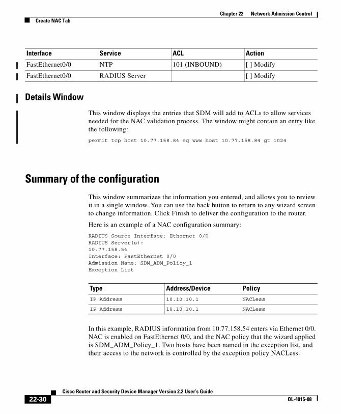
Chapter 22 Network Admission ControlCreate NAC Tab
Details Window
This window displays the entries that SDM will add to ACLs to allow services needed for the NAC validation process. The window might contain an entry like the following:
permit tcp host 10.77.158.84 eq www host 10.77.158.84 gt 1024
Summary of the configurationThis window summarizes the information you entered, and allows you to review it in a single window. You can use the back button to return to any wizard screen to change information. Click Finish to deliver the configuration to the router.
Here is an example of a NAC configuration summary:
RADIUS Source Interface: Ethernet 0/0RADIUS Server(s):10.77.158.54Interface: FastEthernet 0/0Admission Name: SDM_ADM_Policy_1Exception List
In this example, RADIUS information from 10.77.158.54 enters via Ethernet 0/0. NAC is enabled on FastEthernet 0/0, and the NAC policy that the wizard applied is SDM_ADM_Policy_1. Two hosts have been named in the exception list, and their access to the network is controlled by the exception policy NACLess.
FastEthernet0/0 NTP 101 (INBOUND) [ ] Modify
FastEthernet0/0 RADIUS Server [ ] Modify
Interface Service ACL Action
Type Address/Device PolicyIP Address 10.10.10.1 NACLess
IP Address 10.10.10.1 NACLess
22-30Cisco Router and Security Device Manager Version 2.2 User’s Guide
OL-4015-08
Chapter 22 Network Admission ControlEdit NAC Tab
Edit NAC TabThe Edit NAC tab lists the NAC policies configured on the router and enables you to configure other NAC settings. A NAC policy must be configured for each interface on which posture validation is to be performed.
EAPoUDP Timeouts Button
The router and the client use Extensible Authentication Protocol over Unformatted Data Protocol (EAPoUDP) to exchange posture information. Default values for EAPoUDP timeout settings are preconfigured, but you can change the settings if you want to do so.
Agentless Host Policy Button
If a policy for agentless hosts exists on the ACS server, the router can use that policy to handle hosts without installed posture agents. This method of handling agentless hosts can be used when such hosts do not have static IP addresses.
Add, Edit, and Delete Buttons
These buttons allow you to manage the NAC policy list. Click Add to create a new NAC policy. Use the Edit and Delete buttons to modify and remove NAC policies. The Edit and Delete buttons are disabled when no NAC policies have been configured on the router.
NAC Policies List
The name, the interface that the NAC policy is applied to, and the access rule that defines the policy is included in the list. If you enabled NAC on an interface using the Create NAC wizard, the default NAC policy SDM_ADM_POLICY appears in this list.
EAPoUDP ComponentsThis window provides a brief description of the EAPoUDP components that SDM allows you to configure.
22-31Cisco Router and Security Device Manager Version 2.2 User’s Guide
OL-4015-08

Chapter 22 Network Admission ControlEdit NAC Tab
Exception List WindowThis placeholder topic will be removed when the help system for NAC is built. This help topic has already been written for wizard mode. To view it, click on the following link:
NAC Exception List
Exception Policies WindowNAC exception policies control the network access of hosts in the exception list. A NAC exception policy consists of a name, an access rule, and/or a redirect URL. The access rule specifies the destinations that hosts governed by the policy have access to. If a redirect URL is specified in the policy, the policy can point web clients to sites that contain information on how to obtain the latest available virus protection.
An example of a NAC policy entry is shown in the following table:
Access rules associated with NAC policies must be extended ACLs, and must be named. An example of an access rule that might be used in a NAC policy is shown in the following table:
This rule permits any host governed by the policy to send IP traffic to the IP address 172.30.2.10.
Name Access Rule Redirect URL
NACLess nac-rule http://172.30.10/update
Action Source Destination Service Log Attributes
permit any 172.30.2.10 ip
22-32Cisco Router and Security Device Manager Version 2.2 User’s Guide
OL-4015-08
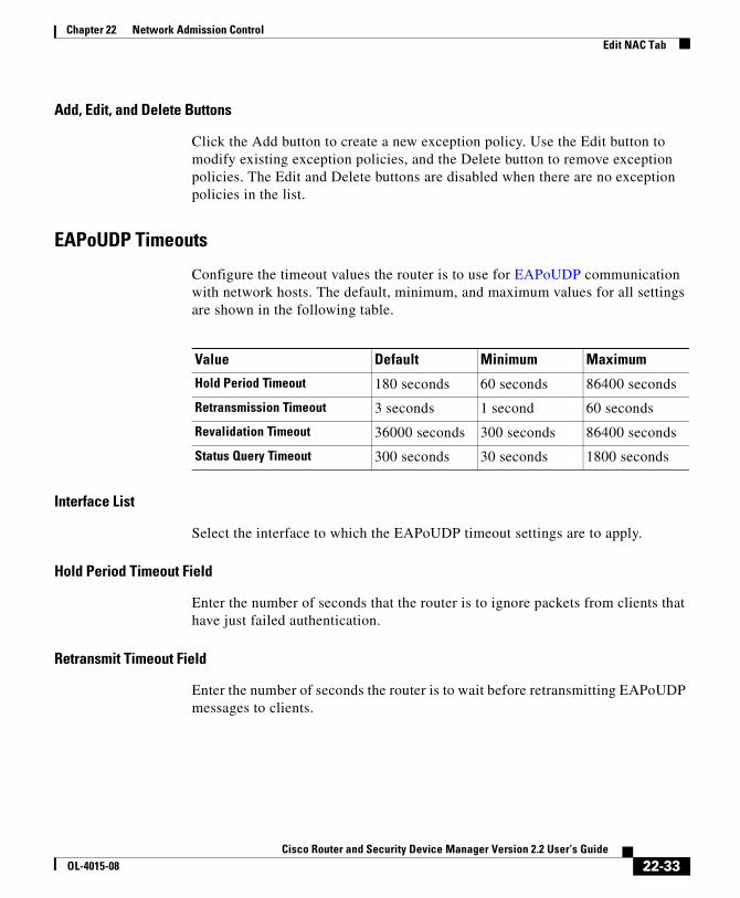
Chapter 22 Network Admission ControlEdit NAC Tab
Add, Edit, and Delete Buttons
Click the Add button to create a new exception policy. Use the Edit button to modify existing exception policies, and the Delete button to remove exception policies. The Edit and Delete buttons are disabled when there are no exception policies in the list.
EAPoUDP Timeouts
Configure the timeout values the router is to use for EAPoUDP communication with network hosts. The default, minimum, and maximum values for all settings are shown in the following table.
Interface List
Select the interface to which the EAPoUDP timeout settings are to apply.
Hold Period Timeout Field
Enter the number of seconds that the router is to ignore packets from clients that have just failed authentication.
Retransmit Timeout Field
Enter the number of seconds the router is to wait before retransmitting EAPoUDP messages to clients.
Value Default Minimum Maximum
Hold Period Timeout 180 seconds 60 seconds 86400 seconds
Retransmission Timeout 3 seconds 1 second 60 seconds
Revalidation Timeout 36000 seconds 300 seconds 86400 seconds
Status Query Timeout 300 seconds 30 seconds 1800 seconds
22-33Cisco Router and Security Device Manager Version 2.2 User’s Guide
OL-4015-08
Chapter 22 Network Admission ControlEdit NAC Tab
Revalidation Timeout Field
The router periodically queries the posture agent on the client to determine the client’s adherence to security policy. Enter the number of seconds that the router should wait between queries.
Status Query Timeout Field
Enter the number of seconds the router should wait between queries to the posture agent on the host.
Reset to Defaults Button
Click to reset all EAPoUDP timeouts to their default values.
Configure these timeout values globally checkbox
Click this checkbox to have these values apply to all interfaces.
Configure a NAC Policy
A NAC policy enables the posture validation process on a router interface, and can be used to control the admission control process by specifying the types of traffic that are to be exempt from posture validation.
Name Field
Enter a name for the policy.
Select an Interface List
Select the interface to which you want to apply the NAC policy. Select an interface that connects network clients to the router.
Admission Rule Field
Use an access rule to exempt specific traffic from triggering the admission control process. Enter the name of the access rule that you want to use for the admission rule. You can also click the button to the right of this field and browse for the access rule, or create a new access rule.
22-34Cisco Router and Security Device Manager Version 2.2 User’s Guide
OL-4015-08

Chapter 22 Network Admission ControlHow Do I...
The access rule must contain deny statements that specify the traffic that is to be exempted from the admission control process. No posture validation triggering occurs if the access rule contains only deny statements.
An example of ACL entries for a NAC admission rule follows:
deny udp any host 10.10.30.10 eq domain
deny tcp any host 10.10.20.10 eq www
permit ip any any
The first deny statement exempts traffic with a destination of port 53 (domain), and the second statement exempts traffic with a destination of port 80(www). The permit statement ending the ACL ensures that posture validation occurs.
How Do I...The following topics contain procedures for performing tasks that the Create NAC wizard does help you to do.
How Do I Configure a NAC Policy Server?The router must have a connection to a Cisco Secure Access Control Server (ACS) version 3.3, configured to use the RADIUS protocol, in order to implement NAC. The document at the following link contains an overview of the configuration process.
http://www.cisco.com/application/pdf/en/us/guest/netsol/ns466/c654/cdccont_0900aecd80217e26.pdf
Documents at the following link explain how to install and configure Cisco Secure ACS for Windows Servers version 3.3.
http://www.cisco.com/univercd/cc/td/doc/product/access/acs_soft/csacs4nt/acs33/index.htm
How Do Install and Configure a Posture Agent on a Host?If you are a registered Cisco.com user, you can download Cisco Trust Agent (CTA) software from the following link:
22-35Cisco Router and Security Device Manager Version 2.2 User’s Guide
OL-4015-08

Chapter 22 Network Admission ControlHow Do I...
http://www.cisco.com/en/US/products/ps5923/index.html
The document at the following link explains how to install and configure CTA software on a host.
http://www.cisco.com/en/US/products/ps5923/products_administration_guide_book09186a008023f7a5.html
The specific installation procedures required to install third-party posture agent software and the optional remediation server vary depending on the software in use. Consult the vendor documentation for complete details.
22-36Cisco Router and Security Device Manager Version 2.2 User’s Guide
OL-4015-08

Cisco Router and Security DeOL-4015-08
C H A P T E R23
Router PropertiesRouter properties let you define the overall attributes of the router, such as the router name, domain name, password, Simple Network Management Protocol (SNMP) status, Domain Name System (DNS) server address, user accounts, router log attributes, virtual type terminal (vty) settings, SSH settings, and other router access security settings.
Device PropertiesThe Properties—Device screen contains host, domain, and password information for your router.
Device Tab
The Device tab contains the following fields.
Host
Enter the name you want to give the router in this field.
Domain
Enter the domain name for your organization. If you do not know the domain name, obtain it from your network administrator.
23-1vice Manager Version 2.2 User’s Guide

Chapter 23 Router PropertiesDate and Time: Clock Properties
Enter the text for Banner
Enter text for the router banner. The router text banner is displayed whenever anyone logs in to the router. It is recommended that the text banner include a message indicating that unauthorized access is prohibited.
Password Tab
The Password tab contains the following fields.
Enable Secret Password
Cisco Router and Security Device Manager (SDM) supports the enable secret password. The enable secret password allows you to control who is able to enter configuration commands on this router. Cisco strongly recommends that you set an enable secret password.The password will not be readable in the SDM Device Properties window, and it will appear in encrypted form in the router’s configuration file. Therefore, you should record this password in case you forget it.
The Cisco IOS version the router is running may also support the enable password. The enable password functions like the enable secret password, but was encrypted in the configuration file. If an enable password is configured using the command-line interface (CLI), it is ignored if an enable secret password is configured.
Current Password
If a password has already been set, this area contains asterisks (*).
Enter New Password
Enter the new enable password in this field.
Reenter New Password
Reenter the password exactly as you entered it in the New Password field.
Date and Time: Clock PropertiesUse this window to view and edit the date and time settings on the router.
23-2Cisco Router and Security Device Manager Version 2.2 User’s Guide
OL-4015-08

Chapter 23 Router PropertiesDate and Time: Clock Properties
Date/Time
You can see the router’s date and time settings on the right side of the SDM status bar. The time and date settings in this part of the Clock Properties window is not updated.
Router Time Source
This field can contain the following values:
• NTP. The router receives time information from an NTP server.
• User Configuration. The time and date values are set manually, via SDM or the CLI.
• No time source. The router has not been configured with time or date settings.
Change Settings
Click to change the date and time settings on the router.
Date and Time PropertiesUse this window to make router date and time settings. You can have SDM synchronize settings with the PC, or you can make settings manually.
Synchronize with my local PC clock
Check to set up SDM to synchronize router date and time settings with the date and time settings on the PC.
Synchronize
Click to have SDM perform a synchronization. SDM adjusts date and time settings in this way only when you click Synchronize; it does not automatically re synchronize with the PC during subsequent sessions. This button is disabled if you have not checked Synchronize with my local PC clock.
23-3Cisco Router and Security Device Manager Version 2.2 User’s Guide
OL-4015-08
Chapter 23 Router PropertiesDate and Time: Clock Properties
Note You must make the Time Zone and Daylight Savings settings on the PC before starting SDM so that SDM will receive the correct settings when you click Synchronize.
Edit Date and Time
Use this area to set the date and time manually. You can choose the month and the year from the drop-down lists, and choose the day of the month in the calendar. The fields in the Time area require values in 24-hour format. You can select your time zone based on Greenwich Mean Time (GMT), or you can browse the list for major cities in your time zone.
If you want the router to adjust time settings for daylight saving time and Standard time, check Automatically adjust clock for daylight savings changes.
Apply
Click to apply the date and time settings you have made in the Date, Time, and Time Zone fields.
NTPNetwork Time Protocol (NTP) allows routers on your network to synchronize their time settings with an NTP server. A group of NTP clients that obtains time and date information from a single source will have more consistent time settings. This window allows you to view the NTP server information that has been configured, to add new information, or to edit or delete existing information.
Note If your router does not support NTP commands, this branch will not appear in the Router Properties tree.
23-4Cisco Router and Security Device Manager Version 2.2 User’s Guide
OL-4015-08

Chapter 23 Router PropertiesDate and Time: Clock Properties
IP Address
The IP address of an NTP server.
If your organization does not have an NTP server, you may want to use a publicly available server, such as the server described at the following URL:
http://www.eecis.udel.edu/~mills/ntp/clock2a.html
Interface
The interface over which the router will communicate with the NTP server.
Prefer
This column contains Yes if this NTP server has been designated as a preferred NTP server. Preferred NTP servers will be contacted before non-preferred servers. There can be more than one preferred NTP server.
Add
Click to add NTP server information.
Edit
Click to edit a selected NTP server configuration.
Delete
Click to delete a selected NTP server configuration.
Add or Edit NTP Server Details
Add or edit NTP server information in this window.
IP Address
Enter or edit the IP address of an NTP server.
23-5Cisco Router and Security Device Manager Version 2.2 User’s Guide
OL-4015-08
Chapter 23 Router PropertiesDate and Time: Clock Properties
Prefer
Click this box if this is to be the preferred NTP server.
Interface
Select the router interface that will provide access to the NTP Server. You can use the show IP routes CLI command to determine which interface has a route to this NTP server.
Note An extended access rule will be created traffic for port 123 traffic and applied to the interface that you select in this window. If an access rule was already in place for this interface, SDM will add statements to permit port 123 traffic on this interface. If the existing rule was a standard access rule, SDM changes it to an extended rule in order to be able to specify traffic type and destination.
Authentication Key
Check this box if the NTP server uses an authentication key, and enter the information required in the fields. The information in these fields must match the key information on the NTP server.
Key Number
Enter the number for the authentication key. The key number range is 0 through 4294967295.
Key Value
Enter the key used by the NTP server. The key value can use any of the letters A through Z, uppercase or lowercase, and can be no longer than 32 characters.
Confirm Key Value
Reenter the key value to confirm accuracy.
23-6Cisco Router and Security Device Manager Version 2.2 User’s Guide
OL-4015-08
Chapter 23 Router PropertiesDate and Time: Clock Properties
SNTPThis window is displayed on Cisco 830 routers. Network Time Protocol (NTP) allows routers on your network to synchronize their time settings with an NTP server. A group of NTP clients that obtain time and date information from a single source will have more consistent time settings. This window allows you to view the NTP server information that has been configured, to add new information, or to edit or delete existing information.
Note If your router does not support NTP commands, this branch will not appear in the Router Properties tree.
Property
The system-defined name for this NTP server.
Value
The IP address for this NTP server.
Add
Click to add NTP server information.
Edit
Click to edit a selected NTP server configuration.
Delete
Click to delete a selected NTP server configuration.
Add an NTP Server
Enter the IP address of an NTP server in this window.
23-7Cisco Router and Security Device Manager Version 2.2 User’s Guide
OL-4015-08

Chapter 23 Router PropertiesDate and Time: Clock Properties
Note An extended access rule will be created traffic for port 123 traffic and applied to the interface that you select in this window. If an access rule was already in place for this interface, SDM will add statements to permit port 123 traffic on this interface. If the existing rule was a standard access rule, SDM changes it to an extended rule in order to be able to specify traffic type and destination.
IP Address
Enter the IP address of the NTP server in dotted-decimal format. For more information see IP Addresses and Subnet Masks.
SyslogUse this window to enable logging of system messages, and to specify syslog servers where logs can be kept. You can enter the host name or IP address of multiple syslog servers.
IP Address/Hostname
Click Add, and enter the IP address or host name of a network host to which you want the router to send logging messages for storage. The Edit and Delete buttons enable you to modify information that you have entered and to delete entries.
Logging to buffer
If you want system messages to be logged to the router’s buffer, enter the buffer size in this field. The larger the buffer, the more entries can be stored before the oldest ones are deleted to make room for new entries. However, you should balance logging needs against router performance.
SNMPThis page lets you enable the SNMP, set SNMP community strings, and enter SNMP trap manager information.
23-8Cisco Router and Security Device Manager Version 2.2 User’s Guide
OL-4015-08

Chapter 23 Router PropertiesDate and Time: Clock Properties
Enable SNMP
Check this box to enable SNMP support. Uncheck this box to disable SNMP support. SNMP is enabled by default.
Community String
SNMP community strings are embedded passwords to Management Information Bases (MIBs). MIBs store data about the router’s operation and are meant to be available to authenticated remote users. There are two types of community strings: “public” community strings, which provide read-only access to all objects in the MIB except community strings, and “private” community strings, which provides read and write access to all objects in the MIB, but do not allow access to the community strings.
The community string table lists all of the configured community strings and their types. Use the Add button to display the Add a Community String dialog box and create new community strings. Click the Edit, and Delete buttons to edit or delete the community string you selected in the table.
Trap Receiver
Enter the IP addresses and community strings of the trap receivers—that is, the addresses where the trap information should be sent. These are normally the IP addresses of the SNMP management stations monitoring your domain. Check with your site administrator to determine the address if you are unsure of it.
Click the Add, Edit, and Delete buttons to administer trap receiver information.
SNMP Server Location
This is a text field that you can use to enter the SNMP server location. It is not a configuration parameter that will affect the operation of the router.
SNMP Server Contact
This is a text field that you can use to enter contact information for a person managing the SNMP server. It is not a configuration parameter that will affect the operation of the router.
23-9Cisco Router and Security Device Manager Version 2.2 User’s Guide
OL-4015-08

Chapter 23 Router PropertiesRouter Access
Router AccessThis window explains which features are included in Router Access.
User Accounts: Configure User Accounts for Router AccessThis window allows you to define accounts and passwords that will enable users to authenticate themselves when logging into the router via HTTP, HTTPS, Telnet, PPP, or other means.
User Name
A user account name.
Password
The user account password, displayed as asterisks (*).
Note The user password is not the same as the enable secret password configured in the Device Properties—Password tab. The user password will enable the specified user to log on to the router and enter a limited set of commands.
Privilege Level
The privilege level for the user.
View Name
If a CLI view has been associated with the user account, the view name appears in this column. Views define the user’s access to SDM based on the user’s role. Click Associate a View with the user for more information.
Note If SDM is launched with a user-defined view, or with an altered SDM-defined view, SDM operates in Monitor mode, and the user has read-only privileges. The SDM features available to be monitored depend on the commands present in the view. Not all features may be available for monitoring by the user.
23-10Cisco Router and Security Device Manager Version 2.2 User’s Guide
OL-4015-08
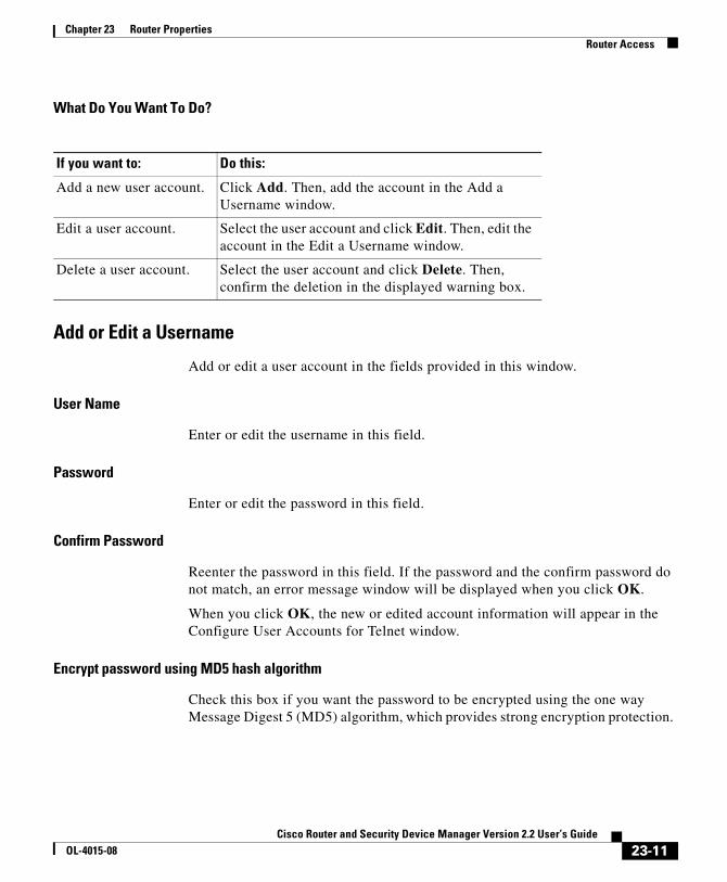
Chapter 23 Router PropertiesRouter Access
What Do You Want To Do?
Add or Edit a Username
Add or edit a user account in the fields provided in this window.
User Name
Enter or edit the username in this field.
Password
Enter or edit the password in this field.
Confirm Password
Reenter the password in this field. If the password and the confirm password do not match, an error message window will be displayed when you click OK.
When you click OK, the new or edited account information will appear in the Configure User Accounts for Telnet window.
Encrypt password using MD5 hash algorithm
Check this box if you want the password to be encrypted using the one way Message Digest 5 (MD5) algorithm, which provides strong encryption protection.
If you want to: Do this:
Add a new user account. Click Add. Then, add the account in the Add a Username window.
Edit a user account. Select the user account and click Edit. Then, edit the account in the Edit a Username window.
Delete a user account. Select the user account and click Delete. Then, confirm the deletion in the displayed warning box.
23-11Cisco Router and Security Device Manager Version 2.2 User’s Guide
OL-4015-08

Chapter 23 Router PropertiesRouter Access
Note Protocols that require the retrieval of clear text passwords, such as CHAP, cannot be used with MD5-encrypted passwords. MD5 encryption is not reversible. To restore the password to clear text, you must delete the user account and recreate it without checking the Encrypt password option.
Privilege Level
Enter the privilege level for the user. When applied to a CLI command, that command can only be executed by users with a privilege level equal to or higher than the level set for the command.
Associate a View with the user
Check the Associate a View for this user option if you want to restrict user access to a specific view. If you are associating a view to any user for the first time, you will be prompted to enter the view password. This option is only available in the Router Access node of the Additional Tasks tree.
View Name:
Select the view you want to associate with this user. Select from the following:
• SDM_Administrator—A user associated to view type of SDM_Administrator has complete access to SDM and all operations supported by SDM can be performed.
• SDM_Monitor—A user associated to view type of SDM_Monitor is able to monitor all the features supported by SDM. The user is not able to deliver configurations using SDM. The user is able to navigate the various areas of SDM, such as Interfaces and Connections, Firewall, and VPN. However, the user interface components in these areas are be disabled.
• SDM_Firewall—A user associated to view type of SDM_Firewall is able to use SDM’s Firewall and Monitor features. The user can configure firewalls and ACLs using the Firewall wizard, Firewall Policy View and the ACL Editor. User interface components in other areas are disabled for this user.
• SDM_EasyVPN_Remote—A user associated to view type SDM_EasyVPN_Remote is able to use SDM’s Easy VPN Remote features. The user is able to create Easy VPN Remote connections and Edit them. User interface components in other areas are disabled for this user.
23-12Cisco Router and Security Device Manager Version 2.2 User’s Guide
OL-4015-08

Chapter 23 Router PropertiesVTYs
Details
The Associate a View for this user area displays details of the selected view. Click on Details button for a more detailed information about the selected view.
View PasswordIf you are associating a view for any user for the first time, you will be prompted to enter the view password for SDM defined views. Use this password to switch between other views.
Enter the View Password
Enter the view password in the View Password: field.
VTYsThis window displays the virtual terminal (vty) settings on your router. The Property column contains configured line ranges and configurable properties for each range. The settings for these properties are contained in the Value column.
This table shows your router vty settings and contains the following columns:
• Line Range—Displays the range of vty connections to which the rest of the settings in the row apply.
• Input Protocols Allowed—Shows the protocols configured for input. Can be Telnet, SSH, or both Telnet and SSH.
• Output Protocols Allowed—Shows the protocols configured for output. Can be Telnet, SSH, or both Telnet and SSH.
• EXEC Timeout—The number of seconds of inactivity after which a session will be terminated.
• Inbound Access-class—The name or number of the access rule applied to the inbound direction of the line range.
• Outbound Access-class—The name or number of the access rule applied to the outbound direction of the line range.
• ACL—If configured, shows the ACL associated with the vty connections.
23-13Cisco Router and Security Device Manager Version 2.2 User’s Guide
OL-4015-08

Chapter 23 Router PropertiesVTYs
• Authentication Policy—The AAA authentication policy associated with this vty line. This field is visible if AAA is configured on the router.
• Authorization Policy—The AAA authorization policy associated with this vty line. This field is visible if AAA is configured on the router.
Note To use SSH as an input or output protocol, you must enable it by clicking SSH in the Additional Tasks tree and generating an RSA key.
Edit VTY LinesThis window lets you edit virtual terminal (vty) settings on your router.
Line Range
Enter the range of vty lines to which the settings made in this window will apply.
Time Out
Enter the number of seconds of inactivity allowed to pass before an inactive connection will be terminated.
Input Protocol
Select the input protocols by clicking the appropriate check boxes.
Telnet
Check this check box to enableTelnet access to your router.
SSH
Check this check box to enable SSH clients to log on to the router.
Output Protocol
Select the output protocols by clicking the appropriate check boxes.
Telnet
Check this check box to enable Telnet access to your router.
23-14Cisco Router and Security Device Manager Version 2.2 User’s Guide
OL-4015-08

Chapter 23 Router PropertiesVTYs
SSH
Check this check box to enable the router to communicate to SSH clients.
Access Rule
You can associate access rules to filter inbound and outbound traffic on the vty lines in the range.
Inbound
Enter the name or number of the access rule you want to filter inbound traffic, or click the button and browse for the access rule.
Outbound
Enter the name or number of the access rule you want to filter inbound traffic, or click the button and browse for the access rule.
Authentication/Authorization
These fields are visible when AAA is enabled on the router. AAA can be enabled by clicking Additional Tasks>AAA>Enable.
Authentication Policy
Select the authentication policy that you want to use for this vty line.
Authorization Policy
Select the authorization policy that you want to use for this vty line.
Configure Management Access PoliciesUse this window to review existing management access policies and to select policies for editing. Management access policies specify which networks and hosts will be able to access the router’s command line interface. In the policy, you can specify which protocols the host or network in the policy can use, and which router interface will carry the management traffic.
23-15Cisco Router and Security Device Manager Version 2.2 User’s Guide
OL-4015-08

Chapter 23 Router PropertiesVTYs
Host/Network
A network address or host IP address. If a network address is given, the policy applies to all hosts on that network. If a host address is given, the policy applies to that host.
A network address is shown in the format network number/network bits, as in the following example:
172.23.44.0/24
For more information on this format, and on how IP addresses and subnet masks are used, see IP Addresses and Subnet Masks.
Management Interface
The router interface over which management traffic will flow.
Permitted Protocols
This column lists the protocols that the specified hosts can use when communicating with the router. The following protocols can be configured:
• SDM—Specified hosts can use SDM.
• Telnet—Specified hosts can use Telnet to access router CLI.
• SSH—Specified hosts can use Secure Shell to access router CLI.
• HTTP, HTTPS—Specified hosts can use Hypertext Transfer Protocol to access the router. If SDM is specified, either HTTP or HTTPS must also be specified.
• HTTP, HTTPS—Specified hosts can use Hypertext Transfer Protocol, Secure, to access the router.
• RCP—Specified hosts can use Remote Copy Protocol to manage files on the router.
• SNMP—Specified hosts can use Simple Network Management Protocol to manage the router.
Add Button
Click to add a management policy, and specify the policy in the Add a Management Policy window.
23-16Cisco Router and Security Device Manager Version 2.2 User’s Guide
OL-4015-08
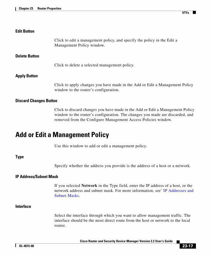
Chapter 23 Router PropertiesVTYs
Edit Button
Click to edit a management policy, and specify the policy in the Edit a Management Policy window.
Delete Button
Click to delete a selected management policy.
Apply Button
Click to apply changes you have made in the Add or Edit a Management Policy window to the router’s configuration.
Discard Changes Button
Click to discard changes you have made in the Add or Edit a Management Policy window to the router’s configuration. The changes you made are discarded, and removed from the Configure Management Access Policies window.
Add or Edit a Management PolicyUse this window to add or edit a management policy.
Type
Specify whether the address you provide is the address of a host or a network.
IP Address/Subnet Mask
If you selected Network in the Type field, enter the IP address of a host, or the network address and subnet mask. For more information, see’ IP Addresses and Subnet Masks.
Interface
Select the interface through which you want to allow management traffic. The interface should be the most direct route from the host or network to the local router.
23-17Cisco Router and Security Device Manager Version 2.2 User’s Guide
OL-4015-08
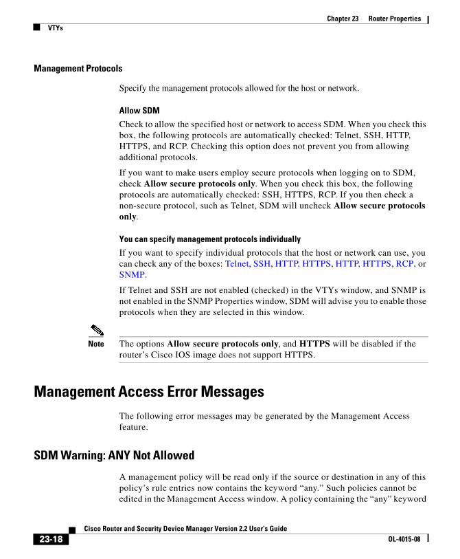
Chapter 23 Router PropertiesVTYs
Management Protocols
Specify the management protocols allowed for the host or network.
Allow SDM
Check to allow the specified host or network to access SDM. When you check this box, the following protocols are automatically checked: Telnet, SSH, HTTP, HTTPS, and RCP. Checking this option does not prevent you from allowing additional protocols.
If you want to make users employ secure protocols when logging on to SDM, check Allow secure protocols only. When you check this box, the following protocols are automatically checked: SSH, HTTPS, RCP. If you then check a non-secure protocol, such as Telnet, SDM will uncheck Allow secure protocols only.
You can specify management protocols individually
If you want to specify individual protocols that the host or network can use, you can check any of the boxes: Telnet, SSH, HTTP, HTTPS, HTTP, HTTPS, RCP, or SNMP.
If Telnet and SSH are not enabled (checked) in the VTYs window, and SNMP is not enabled in the SNMP Properties window, SDM will advise you to enable those protocols when they are selected in this window.
Note The options Allow secure protocols only, and HTTPS will be disabled if the router’s Cisco IOS image does not support HTTPS.
Management Access Error MessagesThe following error messages may be generated by the Management Access feature.
SDM Warning: ANY Not Allowed
A management policy will be read only if the source or destination in any of this policy’s rule entries now contains the keyword “any.” Such policies cannot be edited in the Management Access window. A policy containing the “any” keyword
23-18Cisco Router and Security Device Manager Version 2.2 User’s Guide
OL-4015-08

Chapter 23 Router PropertiesVTYs
can create a security risk because if source is “any” it allows traffic from any network to enter the router, or if destination is “any” it allows access to any node on the network that the local router supports.
You can remove the access entry that caused this message to appear by selecting the rule in the Rules window and clicking Edit. Or, you can disassociate the rule from the interface it is applied to in the Interfaces and Connections window.
SDM Warning: Unsupported Access Control Entry
A management policy will be read only if unsupported access control entries (ACEs) are associated with the interface or vty line to which you applied the management policy. You can use the CLI to remove the unsupported ACEs. Unsupported ACEs are those that contain keywords or syntax that SDM does not support.
SDM Warning: SDM Not Allowed
This message is displayed if you still have not configured a management access policy to allow a host or network to access SDM on this router. It is essential to provide such a policy in order to make SDM on this router accessible.
You cannot navigate to other features or deliver commands to the router until you configure a management access policy to allow access to SDM for a host or network.
SDM Warning: Current Host Not Allowed
This message is displayed if you have not configured a management access policy to allow the current host or network to access SDM on this router. You should create such a policy in order to make SDM on this router accessible from the current host or network. If you don’t, you will lose the connection to the router when you deliver the configuration to the router.
Click Yes to add to a management access policy now for the current host or network.
Click No to proceed without adding a policy for the current host or network. You will lose contact with the router during command delivery, and you will have to log on to SDM using a different host or network.
23-19Cisco Router and Security Device Manager Version 2.2 User’s Guide
OL-4015-08

Chapter 23 Router PropertiesVTYs
SSHThis router implements Secure Shell (SSH) Server, a feature that enables an SSH client to make a secure, encrypted connection to a Cisco router. This connection provides functionality that is similar to that of an inbound Telnet connection, but that provides strong encryption to be used with Cisco IOS software authentication. The SSH server in Cisco IOS software will work with publicly and commercially available SSH clients. This feature is disabled if the router is not using an IPSEC DES or 3DES Cisco IOS software image, and if the SSH branch of the Additional Tasks tree does not appear.
SSH uses an RSA crypto key to encrypt data traveling between the router and the SSH client. Generating the RSA key in this window enables SSH communication between the router and the SSH clients.
Status
Crypto key is not set on this device
This text appears if there is no crypto key configured for the device. If there is no key configured, you can enter a modulus size, and generate a key.
RSA key is set on this router
This text appear if a crypto key has been generate. SSH is enabled on this router.
Key modulus size
This button is visible if no crypto key has been generated. Click this button and enter the modulus size you want to give the key. If you want a modulus value between 512 and 1024 enter an integer value that is a multiple of 64. If you want a value higher than 1024, you can enter 1536 or 2048. If you enter a value greater than 512, key generation may take a minute or longer.
Generate RSA Key
Click this button to generate a crypto key for the router using the modulus size you entered. If the crypto key has already been generated, this button is disabled.
23-20Cisco Router and Security Device Manager Version 2.2 User’s Guide
OL-4015-08
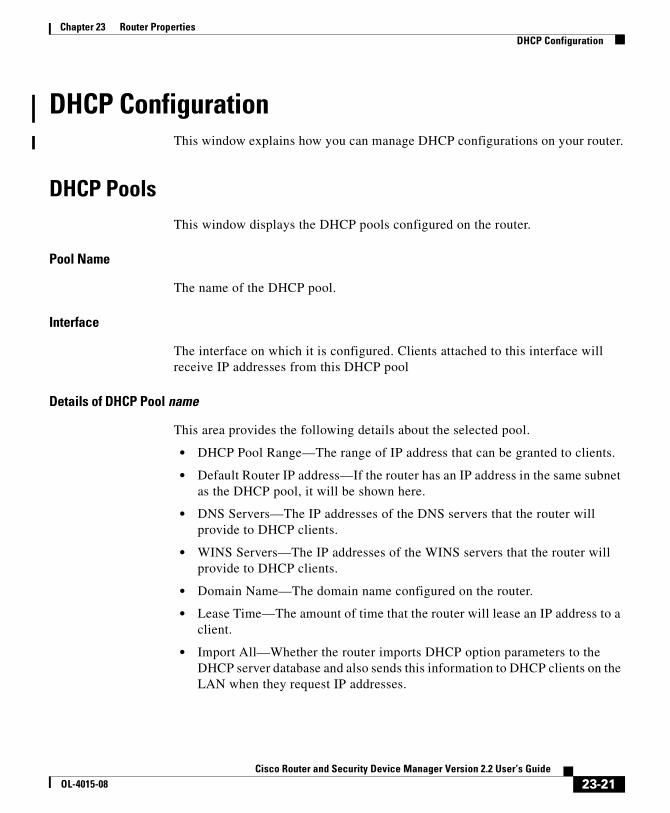
Chapter 23 Router PropertiesDHCP Configuration
DHCP ConfigurationThis window explains how you can manage DHCP configurations on your router.
DHCP PoolsThis window displays the DHCP pools configured on the router.
Pool Name
The name of the DHCP pool.
Interface
The interface on which it is configured. Clients attached to this interface will receive IP addresses from this DHCP pool
Details of DHCP Pool name
This area provides the following details about the selected pool.
• DHCP Pool Range—The range of IP address that can be granted to clients.
• Default Router IP address—If the router has an IP address in the same subnet as the DHCP pool, it will be shown here.
• DNS Servers—The IP addresses of the DNS servers that the router will provide to DHCP clients.
• WINS Servers—The IP addresses of the WINS servers that the router will provide to DHCP clients.
• Domain Name—The domain name configured on the router.
• Lease Time—The amount of time that the router will lease an IP address to a client.
• Import All—Whether the router imports DHCP option parameters to the DHCP server database and also sends this information to DHCP clients on the LAN when they request IP addresses.
23-21Cisco Router and Security Device Manager Version 2.2 User’s Guide
OL-4015-08
Chapter 23 Router PropertiesDHCP Configuration
Add
Select this option to create a new DHCP Pool. User need to specify DHCP Pool name, DHCP Pool network, DHCP pool ip address range and Lease time. Also DNS servers, WINS server, domain name and default router can be configured in the DHCP pool, but these were option fields.
Edit
Select this option to edit an existing DHCP Pool.
Delete
Select this option to delete a DHCP pool.
DHCP Pool Status
Clicking this button shows the IP Addresses leased by the selected pool. If a DHCP pool contains any parameters other than pool network, IP address range, lease time DNS servers, WINS servers, domain name and default router, SDM shows this pool as read-only. Also, if a pool contains a discontinuous range of IP addresses it will be shown as read-only.
Add or Edit DHCP PoolAdd or Edit a DHCP pool in this window. You cannot edit SDM-default pools.
DHCP Pool Name
Provide a name for the DHCP pool in this field.
DHCP Pool Network
Enter the network from which the IP addresses in the pool will be taken. For example, 192.168.233.0. This cannot be the IP address of an individual host.
23-22Cisco Router and Security Device Manager Version 2.2 User’s Guide
OL-4015-08

Chapter 23 Router PropertiesDHCP Configuration
Subnet Mask
Enter the subnet mask. The subnet mask of the example network address could be 255.255.255.0, providing 255 IP addresses.
DHCP Pool
Enter the starting and ending IP addresses in the range. The starting address based on the example network number would be 192.168.233.1. The ending address would be 192.168.233.254.
Lease Length
Enter the amount of time that addresses are to be leased to clients. You can specify that leased addresses never expire, or you can specify the lease time in days, hours, and minutes. You cannot specify more than 365 days, more than 23 hours, or more than 59 minutes.
DHCP Options
Enter information for DNS server, WINS servers, the domain name, and the default router in the DHCP options fields. These values will be sent to the DHCP clients when they request an IP address.
Import all DHCP Options into the DHCP server database
Click this option if you want to import DHCP option parameters to the DHCP server database and also send this information to DHCP clients on the LAN when they request IP addresses.
DHCP BindingsThis window shows existing manual DHCP bindings. A manual DHCP binding allows you to allocate the same IP address to a specific client each time the client requests an IP address from the available DHCP pools.
You can also add new bindings, edit existing bindings, or delete existing bindings.
Binding Name
The name assigned to the DHCP binding.
23-23Cisco Router and Security Device Manager Version 2.2 User’s Guide
OL-4015-08
Chapter 23 Router PropertiesDHCP Configuration
Host/IP Mask
The IP address and mask bound to the client.
MAC Address
The MAC address of the client.
Type
The type of MAC address is one of the following:
• Ethernet
Client has a hardware address.
• IEEE802
Client has a hardware address.
• <None>
Client has a client identifier.
Client Name
An optional name assigned to the client.
Add Button
Click to add a new manual DHCP binding.
Edit Button
Click to edit the specified manual DHCP binding.
Delete Button
Click to delete the specified manual DHCP binding.
Add or Edit DHCP BindingThis window allows you to add or edit existing manual DHCP bindings.
23-24Cisco Router and Security Device Manager Version 2.2 User’s Guide
OL-4015-08

Chapter 23 Router PropertiesDHCP Configuration
Name
Enter the name you want for the DHCP binding. If you are editing the DHCP binding, the name field is read-only.
Host IP
Enter the IP address you want to bind to the client. The address should be from the DHCP pool available to the client. Do not enter an address in use by another DHCP binding.
Mask
Enter the mask used for the host IP address.
Identifier
From the drop-down menu, choose a method for identifying the client with a MAC address.
MAC Address
Enter the MAC address of the client. Do not enter an address in use by another DHCP binding.
Type
If you chose Hardware Address from the Identifier drop-down menu, choose Ethernet or IEEE802 to set the MAC address type of the client.
Client Name (Optional)
Enter a name to identify the client. The name should be a hostname only, not a domain-style name. For example, router is an acceptable name, but router.cisco.com is not.
23-25Cisco Router and Security Device Manager Version 2.2 User’s Guide
OL-4015-08

Chapter 23 Router PropertiesDNS Properties
DNS PropertiesThe Domain Name System (DNS) is a database of Internet host names with their corresponding IP addresses distributed over designated DNS servers. It enables network users to refer to hosts by name, rather than by IP addresses, which are harder to remember. Use this window to enable the use of DNS servers for host name to address translation.
Enable DNS-based hostname to address translation
Check this box to enable the router to use the DNS. Uncheck this box if you do not want to use the DNS.
DNS IP Address
Enter the IP addresses of the DNS servers that you want the router to send DNS requests to.
Click the Add, Edit, and Delete buttons to administer DNS IP address information.
Dynamic DNS MethodsThis window shows a list of dynamic DNS methods.
Each dynamic DNS method shown will send with its update the host name and domain name configured in Configure > Additional Tasks > Router Properties. However, if you create a dynamic DNS method when configuring a WAN interface, you can override the host name and domain name configured in Configure > Additional Tasks > Router Properties. The new host name and domain name will apply only to that dynamic DNS method.
Some dynamic DNS methods are read-only. These were configured in the Cisco IOS software through the CLI, and cannot be edited or deleted. To make these read-only methods editable, use the CLI to change the internal cache or host group options to HTTP or IETF.
Add Button
Click the Add button to create a new dynamic DNS method.
23-26Cisco Router and Security Device Manager Version 2.2 User’s Guide
OL-4015-08

Chapter 23 Router PropertiesDynamic DNS Methods
Edit Button
To edit a dynamic DNS method, choose it from the list of existing dynamic DNS methods and then click the Edit button.
Delete Button
To edit a dynamic DNS method, choose it from the list of existing dynamic DNS methods and then click the Delete button.
Note A warning appears if you attempt to delete a dynamic DNS method that has been associated with one or more interfaces.
Add or Edit Dynamic DNS MethodThis window allows you to add or edit a dynamic DNS method. Set the type of method by choosing HTTP or IETF.
HTTP
HTTP is a dynamic DNS method type that updates a DNS service provider with changes to the associated interface’s IP address.
Server
If using HTTP, choose the domain address of the DNS service provider from the drop-down menu.
Username
If using HTTP, enter a username for accessing the DNS service provider.
Password
If using HTTP, enter a password for accessing the DNS service provider.
23-27Cisco Router and Security Device Manager Version 2.2 User’s Guide
OL-4015-08
Chapter 23 Router PropertiesDynamic DNS Methods
IETF
IETF is a dynamic DNS method type that updates a DNS server with changes to the associated interface’s IP address.
If using IETF, configure a DNS server for the router in Configure > Additional Tasks > DNS.
23-28Cisco Router and Security Device Manager Version 2.2 User’s Guide
OL-4015-08

Cisco Router and Security DeOL-4015-08
C H A P T E R24
ACL EditorRules define how the router will respond to a particular kind of traffic. Using SDM, you can create access rules that cause the router to block certain types of traffic while permitting other types, NAT rules that define the traffic that is to receive address translation, and IPSec rules that specify which traffic is to be encrypted. SDM also provides default rules that are used in guided configurations, and that you can examine and use when you create your own access rules. It also allows you to view rules that were not created using SDM, called external rules, and rules with syntax that SDM does not support, called unsupported rules.
Use the Rules screen to view a summary of the rules in the router’s configuration and to navigate to other windows to create, edit, or delete rules.
Category
A type of rule. One of the following:
Access Rules Rules that govern the traffic that can enter and leave the network. These rules are used by router interfaces, and by VTY lines that let users log on to the router.
NAT Rules Rules that determine how private IP addresses are translated into valid Internet IP addresses.
IPSec Rules Rules that determine which traffic will be encrypted on secure connections.
24-1vice Manager Version 2.2 User’s Guide
Chapter 24 ACL EditorUseful Procedures for Access Rules and Firewalls
No. of Rules
The number of rules of this type.
Description
A description of the rule if one has been entered.
To configure rules:
Click the category of rule in the rule tree to display the window for that type of rule. Create and edit rules from that window.
The help topic for these windows contains general procedures that you may find helpful. Useful Procedures for Access Rules and Firewalls contains step by step procedures for other tasks.
Useful Procedures for Access Rules and FirewallsThis section contains procedures that you may find useful.
• How Do I View Activity on My Firewall?
• How Do I Configure a Firewall on an Unsupported Interface?
• How Do I Configure a Firewall After I Have Configured a VPN?
• How Do I Permit Specific Traffic Through a DMZ Interface?
Unsupported Rules Rules that have not been created using SDM, and that SDM does not support. These rules are read only, and cannot be modified using SDM.
Externally Defined Rules Rules that have not been created using SDM, but that SDM does support. These rules may not be associated with any interface.
SDM Default Rules These rules are predefined rules that are used by SDM wizards and that you can apply in the Additional Tasks>ACL Editor windows.
24-2Cisco Router and Security Device Manager Version 2.2 User’s Guide
OL-4015-08
Chapter 24 ACL EditorRules Windows
• How Do I Modify an Existing Firewall to Permit Traffic from a New Network or Host?
• How Do I Configure NAT Passthrough for a Firewall?
• How Do I Permit Traffic Through a Firewall to My Easy VPN Concentrator?
• How Do I Associate a Rule with an Interface?
• How Do I Disassociate an Access Rule from an Interface
• How Do I Delete a Rule That Is Associated with an Interface?
• How Do I Create an Access Rule for a Java List?
Rules Windows These windows let you examine, create, edit, and delete rules.
• Access Rules window—Access rules most commonly define the traffic that you want to permit or deny entry to your LAN or exit from your LAN, but they can be used for other purposes as well.
• NAT Rules window—NAT rules are used to specify a set of addresses to translate.
• IPSec Rules window—IPSec rules are extended rules used in IPSec policies to specify which traffic will be encrypted for VPN connections.
• Unsupported Rules window—Unsupported rules contain syntax or keywords that SDM does not support. Unsupported rules may affect the way the router operates, but are marked as read-only by SDM.
• Externally Defined Rules window—Externally defined rules are those that SDM was not used to create.
• SDM Default Rules window—SDM default rules are pre-defined access rules. They are used in guided first-time configurations, and you can use them in configurations that you create.
• NAC Rules window. NAC rules are used in the NAC exception policy to specify hosts that are to be exempted from the NAC validation process. They are also used to define the hosts or networks in which posture agents are installed.
24-3Cisco Router and Security Device Manager Version 2.2 User’s Guide
OL-4015-08
Chapter 24 ACL EditorRules Windows
The upper portion of the screen lists the access rules that have been configured on this router. This list does not contain SDM default rules. To view SDM default rules, click the SDM Default Rules branch of the Rules tree.
The lower portion of the window lists the rule entries associated with the selected rule. A rule entry consists of criteria that incoming or outgoing traffic is compared against, and the action to take on traffic matching the criteria. If traffic does not match the criteria of any of the entries in this box, it is dropped.
First column
This column may contain icons that indicate the status of a rule.
Name/Number
The name or the number of the access rule.
The numbers 1 through 99 are used to identify standard access lists. The numbers 100 through 199 are used to identify extended access lists. Names, which can contain alphabetic characters, allow you to extend the range of standard access lists beyond 99, and extended access lists beyond 199.
Used By
The name of the interface or VTY numbers to which this rule has been applied.
Type
The type of rule, either standard or extended.
Standard rules compare a packet’s source IP address against its IP address criteria to determine a match. The rule’s IP address criteria can be a single IP address, or portions of an IP address, defined by a wildcard mask.
Extended rules can examine a greater variety of packet fields to determine a match. Extended rules can examine both the packet’s source and destination IP addresses, the protocol type, the source and destination ports, and other packet fields.
If the rule is read only, the read-only icon will appear in this column.
24-4Cisco Router and Security Device Manager Version 2.2 User’s Guide
OL-4015-08
Chapter 24 ACL EditorRules Windows
Access rules can be either standard rules or extended rules. IPSec rules have to extended rules because they must be able to specify a service type. Externally defined and unsupported rules may be either standard or extended.
Description
A description of the rule, if one has been entered.
First Column (Rule Entry Area)
Action
The action to take when a packet matching the criteria in this entry arrives on the interface. Either Permit or Deny:
• Permit—Allow traffic matching the criteria in this row.
• Deny—Do not allow traffic matching the criteria in this row.
Click Meanings of the Permit and Deny Keywords to learn more about the action of permit and the action of deny in the context of a specific type of rule.
Source
The source IP address criteria that the traffic must match. This column may contain:
• An IP address and wildcard mask. The IP address specifies a network, and the wildcard mask specifies how much of the rule’s IP address the IP address in the packet must match.
• The keyword any. Any indicates that the source IP address can be any IP address
• A host name.
Permit traffic.
Deny traffic.
24-5Cisco Router and Security Device Manager Version 2.2 User’s Guide
OL-4015-08

Chapter 24 ACL EditorRules Windows
Destination
For extended rules, the destination IP address criteria that the traffic must match. The address may be for a network, or a specific host. This column may contain:
• An IP address and wildcard mask. The IP address specifies a network, and the wildcard mask specifies how much of the rule’s IP address the IP address in the packet must match.
• The keyword any. Any indicates that the source IP address can be any IP address
• A host name.
Service
For extended rules, the service specifies the type of traffic that packets matching the rule must contain. This is shown by displaying the service, such as echo-reply, followed by the protocol, such as ICMP. A rule permitting or denying multiple services between the same end points must contain an entry for each service.
Attributes
This field can contain other information about this entry, such as whether logging has been enabled.
Description
A short description of the entry.
What do you want to do?
If you want to: Do this:
Add a rule. Click the Add button and create the rule in the windows displayed.
Edit a rule, or edit a rule entry. Select the access rule and click Edit. Then edit the rule in the Edit rule window displayed.
Associate a rule with an interface. See How Do I Associate a Rule with an Interface?
24-6Cisco Router and Security Device Manager Version 2.2 User’s Guide
OL-4015-08
Chapter 24 ACL EditorRules Windows
Add or Edit a RuleThis window lets you add or edit a rule you have selected in the Rules window. You can rename or renumber the rule, add, change, reorder, or delete rule entries, and add or change the description of the rule.
Name/Number
Add or edit the name or number of the rule.
Standard rules must be numbered in the range 1–99, or 1300–1999.
Extended rules must be numbered in the range 100–199 or 2000–2699.
Names, which can contain alphabetic characters, allow you to associate a meaningful label to the access rule.
Type
Select the type of rule you are adding. Standard rules let you have the router examine the source host or network in the packet. Extended rules let you have the router examine the source host or network, the destination host or network, and the type of traffic that the packet contains.
Description
You can provide a description of the rule in this field. The description must be less than 100 characters long.
Delete a rule that has not been associated with an interface.
Select the Access rule, and click Delete.
Delete a rule that has been associated with an interface
SDM does not permit you to delete a rule that has been associated with an interface. In order to delete the rule, you must first disassociate it from the interface. See How Do I Delete a Rule That Is Associated with an Interface?
What I want to do is not described here. The following link contains procedures that you may want to consult: Useful Procedures for Access Rules and Firewalls.
If you want to: Do this:
24-7Cisco Router and Security Device Manager Version 2.2 User’s Guide
OL-4015-08

Chapter 24 ACL EditorRules Windows
Rule Entry List
This list shows the entries that make up the rule. You can add, edit, and delete entries. You can also reorder them to change the order in which they are evaluated.
Observe the following guidelines when creating rule entries:
• There must be at least one permit statement in the list; otherwise, all traffic will be denied.
• A permit all or deny all entry in the list must be the last entry.
• Standard entries and extended entries cannot be mixed in the same rule.
• No duplicate entries can exist in the same rule.
Clone
Click this button to use the selected entry as a template for a new entry. This feature can save you time, and help reduce errors. For example, if you want to create a number of extended rule entries with the same source and destination, but different protocols or ports, you could create the first one using the Add button. After creating the first entry, you could copy it using Clone, and change the protocol field or port field to create a new entry.
Interface Association
Click the Associate button to apply the rule to an interface.
Note The Associate button is enabled only if you are adding a rule from the Access Rules window.
24-8Cisco Router and Security Device Manager Version 2.2 User’s Guide
OL-4015-08

Chapter 24 ACL EditorRules Windows
What do you want to do?
Associate with an InterfaceYou can use this window to associate a rule you have created from the Access Rules window with an interface and to specify whether it applies to outbound traffic or inbound traffic.
If you want to: Do this:
Add or edit a rule entry. Click Add, and create the entry in the window displayed. Or click Edit, and change the entry in the window displayed.
Add a rule entry using an existing entry as a template.
Select the entry you want to use as a template, and click Clone. Then create the entry in the dialog box displayed.
The dialog box displays the contents of the entry you selected so that you can edit it to create a new entry.
Reorder rule entries to make sure that the router evaluates particular entries.
Select the rule entry, and click the Move Up or the Move Down button to move the entry where you want it.
Associate a rule with an interface.
Click Associate and select the interface and direction in the Associate with an Interface window.
If the Associate button is not enabled, you can associate the rule with an interface by double-clicking the interface in the Interfaces and Connections window and using the Associate tab.
Delete a rule entry. Select the rule entry, and click Delete. Then confirm deletion in the Warning window displayed.
Learn more about rules. Explore the resources on Cisco.com. The following link contains information about IP access lists:
http://www.cisco.com/en/US/products/sw/secursw/ps1018/products_tech_note09186a00800a5b9a.shtml
What I want to do is not described here.
The following link contains procedures that you may want to consult: Useful Procedures for Access Rules and Firewalls
24-9Cisco Router and Security Device Manager Version 2.2 User’s Guide
OL-4015-08

Chapter 24 ACL EditorRules Windows
Select an Interface
Select the interface to which you want this rule to apply.
Specify a Direction
If you want the router to check packets inbound to the interface, click Inbound. The router checks for a match with the rule before routing it; the router accepts or drops the packet based on whether the rule states permit or deny. If you want the router to forward the packet to the outbound interface before comparing it to the entries in the access rule, click Outbound.
If Another Rule is Already Associated with the Interface
If an information box appears that tells that another Access Rule is associated with the interface and direction you specified, you can either cancel the operation, or you can continue, by appending the rule entries to the rule that is already applied to the interface, or by disassociating the rule with the interface and associating the new rule.
24-10Cisco Router and Security Device Manager Version 2.2 User’s Guide
OL-4015-08

Chapter 24 ACL EditorRules Windows
What do you want to do?
Add a Standard Rule EntryA standard rule entry allows you to permit or deny traffic that came from a specified source. The source can be a network or a host within a specific network. You can create a single rule entry in this window, but you can return to this window to create additional entries for a rule if you need to.
If you want to: Do this:
Cancel the operation and preserve the association between the interface and the existing rule.
Click No. The association between the existing rule and the interface is preserved, and the rule that you created in the Add a Rule window is saved.
You can examine the existing rule and the new rule and decide whether you want to replace the existing rule or to merge the entries of the new rule with the existing rule.
Continue, and merge the entries of the rule you created with the entries of the existing rule.
Click Yes. Then, when the window appears that asks whether you want to merge or replace the existing rule, click Merge.
The entries you created for the new rule are appended after the last entry of the existing rule.
Note If the rule you want to merge is not compatible with the existing rule, you will be allowed only to replace the existing rule.
Continue, and replace the rule existing rule with the rule you created.
Click Yes. Then, when the window appears that asks you if you want to merge or replace the existing rule, click Replace.
The rule you are replacing is not erased. It is just disassociated with the interface and direction.
24-11Cisco Router and Security Device Manager Version 2.2 User’s Guide
OL-4015-08
Chapter 24 ACL EditorRules Windows
Note Any traffic that does not match the criteria in one of the rule entries you create is implicitly denied. To ensure that traffic you do not intend to deny is permitted, you must append explicit permit entries to the that rule you are configuring.
Action
Select the action you want the router to take when a packet matches the criteria in the rule entry. The choices are Permit and Deny. What Permit and Deny do depends on the type of rule in which they are used. In SDM, standard rule entries can be used in access rules, NAT rules, and in access lists associated with route maps. Click Meanings of the Permit and Deny Keywords to learn more about the action of Permit and the action of Deny in the context of a specific type of rule.
Source Host/Network
The source IP address criteria that the traffic must match. The fields in this area of the window change, based on the value of the Type field.
Type
Select one of the following:
• A Network. Select if you want the action to apply to all the IP addresses in a network.
• A Host Name or IP Address. Select if you want the action to apply to a specificc host or IP address.
• Any IP address. Select if you want the action to apply to any IP address.
IP Address
If you selected A Network or if you selected A Host Name or IP address, enter the IP address in this field. If the address you enter is a network address, enter a wildcard mask to specify the parts of the network address that must be matched.
24-12Cisco Router and Security Device Manager Version 2.2 User’s Guide
OL-4015-08

Chapter 24 ACL EditorRules Windows
Mask
If you selected A Network or if you selected A Host Name or IP address, either select the wildcard mask from this list, or enter a custom wildcard mask. A binary 0 in a wildcard mask means that the corresponding bit in a packet’s IP address must match exactly. A binary 1 in a wildcard mask means that the corresponding bit in the packet’s IP address need not match.
Hostname/IP
If you selected A Host Name or IP address in the Type field, enter the name oro the IP address of the host. If you enter a hostname, the router must be configured to use a DNS server.
Description
You can enter a short description of the entry in this field. The description must be fewer than 100 characters long.
Log Matches Against This Entry
If you have specified syslog in System Properties, you can check this box; matches will be recorded in the system log.
Add an Extended Rule EntryAn extended rule entry allows you to permit or deny traffic based on its source and destination and on the protocol and service specified in the packet.
Note Any traffic that does not match the criteria in one of the rule entries you create is implicitly denied. To ensure that traffic you do not intend to deny is permitted, you must append explicit permit entries to the rule that you are configuring.
Action
Select the action you want the router to take when a packet matches the criteria in the rule entry. The choices are Permit and Deny. If you are creating an entry for an IPSec rule, the choices are protect the traffic and don’t protect the traffic.
24-13Cisco Router and Security Device Manager Version 2.2 User’s Guide
OL-4015-08

Chapter 24 ACL EditorRules Windows
What Permit and Deny do depends on the type of rule in which they are used. In SDM, extended rule entries can be used in access rules, NAT rules, IPSec rules, and access lists associated with route maps. Click Meanings of the Permit and Deny Keywords to learn more about the action of Permit and the action of Deny in the context of a specific type of rule.
Source Host/Network
The source IP address criteria that the traffic must match. The fields in this area of the window change, based on the value of the Type field.
Type
Select one of the following:
• A specific IP address. This can be a network address, or the address of a specific host.
• A host name.
• Any IP address.
IP Address
If you selected A specific IP address, enter the IP address in this field. If the address you enter is a network address, enter a wildcard mask to specify the parts of the network address that must be matched.
Mask
If you selected A specific IP address, either select the wildcard mask from this list, or enter a custom wildcard mask. A binary 0 in a wildcard mask means that the corresponding bit in the packet’s IP address must match exactly. A binary 1 in a wildcard mask means that the corresponding bit in the packet’s IP address need not match.
Hostname
If you selected A host name in the Type field, enter the name of the host.
Destination Host/Network
The source IP address criteria that the traffic must match. The fields in this area of the window change, based on the value of the Type field.
24-14Cisco Router and Security Device Manager Version 2.2 User’s Guide
OL-4015-08

Chapter 24 ACL EditorRules Windows
Type
Select one of the following:
• A specific IP address. This can be a network address or the address of a specific host.
• A host name.
• Any IP address.
Mask
If you selected A specific IP address, either select the wildcard mask from this list or enter a custom wildcard mask. A binary 0 in a wildcard mask means that the corresponding bit in the packet’s IP address must match exactly. A binary 1 in a wildcard mask means that the corresponding bit in the packet’s IP address need not match.
Hostname
If you selected A host name in the Type field, enter the name of the host.
Description
You can enter a short description of the entry in this field. The description must be fewer than 100 characters long.
Protocol and Service
Select the protocol and service, if applicable, that you want the entry to apply to. The information that you provide differs from protocol to protocol. Click the protocol to see what information you need to provide.
Source Port
Available when either TCP or UDP is selected. Setting this field will cause the router to filter on the source port in a packet. It is rarely necessary to set a source port value for a TCP connection. If you are not sure you need to use this field, leave it set to = any.
Destination Port
Available when either TCP or UDP is selected. Setting this field will cause the router to filter on the destination port in a packet.
24-15Cisco Router and Security Device Manager Version 2.2 User’s Guide
OL-4015-08
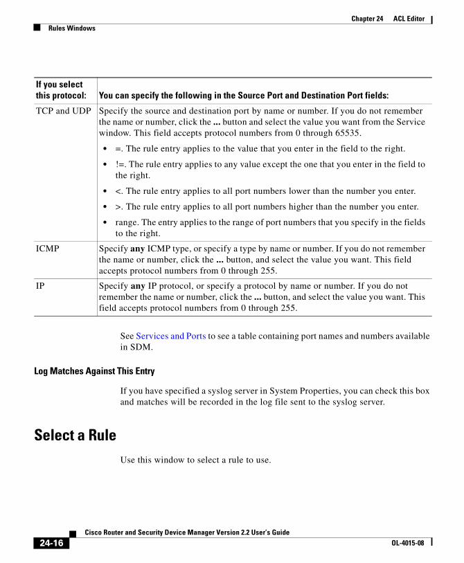
Chapter 24 ACL EditorRules Windows
See Services and Ports to see a table containing port names and numbers available in SDM.
Log Matches Against This Entry
If you have specified a syslog server in System Properties, you can check this box and matches will be recorded in the log file sent to the syslog server.
Select a RuleUse this window to select a rule to use.
If you select this protocol: You can specify the following in the Source Port and Destination Port fields:
TCP and UDP Specify the source and destination port by name or number. If you do not remember the name or number, click the ... button and select the value you want from the Service window. This field accepts protocol numbers from 0 through 65535.
• =. The rule entry applies to the value that you enter in the field to the right.
• !=. The rule entry applies to any value except the one that you enter in the field to the right.
• <. The rule entry applies to all port numbers lower than the number you enter.
• >. The rule entry applies to all port numbers higher than the number you enter.
• range. The entry applies to the range of port numbers that you specify in the fields to the right.
ICMP Specify any ICMP type, or specify a type by name or number. If you do not remember the name or number, click the ... button, and select the value you want. This field accepts protocol numbers from 0 through 255.
IP Specify any IP protocol, or specify a protocol by name or number. If you do not remember the name or number, click the ... button, and select the value you want. This field accepts protocol numbers from 0 through 255.
24-16Cisco Router and Security Device Manager Version 2.2 User’s Guide
OL-4015-08

Chapter 24 ACL EditorRules Windows
Rule Category
Select the rule category that you want to select from. The rules in the category you select will appear in the box below the list. If no rules appear in the box, no rules of that category have been defined.
Name/Number
The name or number of the rule.
Used By
How the rule is being used. For example, if the rule has been associated with an interface, the name of the interface. If the rule is being used in an IPSec policy, the name of the policy. Or, if the rule has been used by NAT, this column contains the value NAT.
Description
A description of the rule.
Preview
This area of the screen displays the entries of the selected rule.
Action
Either Permit or Deny. See Meanings of the Permit and Deny Keywords to learn more about the action of Permit and the action of Deny in the context of a specific type of rule.
Source
The source IP address criteria that the traffic must match. This column may contain the following:
• An IP address and wildcard mask. The IP address specifies a network, and the wildcard mask specifies how much of the rule’s IP address the IP address in the packet must match.
• The keyword any. Any indicates that the source IP address can be any IP address
• A host name.
24-17Cisco Router and Security Device Manager Version 2.2 User’s Guide
OL-4015-08

Chapter 24 ACL EditorRules Windows
Destination
For extended rules, the destination IP address criteria that the traffic must match. The address may be for a network, or a specific host. This column may contain the following:
• An IP address and wildcard mask. The IP address specifies a network, and the wildcard mask specifies how much of the rule’s IP address the IP address in the packet must match.
• The keyword any. Any indicates that the source IP address can be any IP address
• A host name.
Service
For extended rules, the service specifies the type of traffic that packets matching the rule must contain. This is shown by displaying the service, such as echo-reply, followed by the protocol, such as ICMP. A rule permitting or denying multiple services between the same endpoints must contain an entry for each service.
24-18Cisco Router and Security Device Manager Version 2.2 User’s Guide
OL-4015-08
Cisco Router and Security DeOL-4015-08
C H A P T E R25
Port-to-Application MappingPort-to-Application Mapping (PAM) allows you to customize TCP and UDP port numbers for network services and applications. PAM uses this information to support network environments that run services using ports that are different from the registered or well-known ports associated with an application.
The information that PAM maintains enables Context-Based Access Control (CBAC) supported services to run on nonstandard ports. Previously, CBAC was limited to inspecting traffic using only the well-known or registered ports associated with an application. Now, PAM allows network administrators to customize network access control for specific applications and services.
Port-to-Application MappingsThis window displays the port-to-application mappings configured on the router and allows you to add, edit and remove PAM entries. Each row in the window displays a PAM entry, and entries are grouped according to type.
Add, Edit, and Delete Buttons
Use these buttons to create, edit, or remove PAM entries. Clicking the Add button lets you create entries that map nonstandard port numbers to protocol names. Clicking the Edit button lets you make changes to user-defined entries. Entries with the value System Defined in the Protocol Type column cannot be edited or deleted.
25-19vice Manager Version 2.2 User’s Guide
Chapter 25 Port-to-Application MappingPort-to-Application Mappings
Application Protocol Column
This column contains the name of the application protocol, and the names of the protocol types. For example, the FTP and the TFTP entries are found under the File Transfer protocol type.
Port Type Column
This list appears if the router is running a Cisco IOS image that allows you to specify whether this port map entry applies to TCP or to UDP traffic.
Port Column
This column contains the port number. For example the system-defined entry for HTTP would have the port number 80 in this column. A user-defined entry for HTTP might have the port number 8080 or another custom-defined number in this column.
Protocol Type Column
A row in this column displays one of the following values:
• User-Defined—The entry contains a nonstandard mapping between a protocol and protocol number. The entry could be associated with a host IP address identified by the access control list (ACL) whose number is displayed in the Access List column.
• System-Defined—The entry contains a standard, registered mapping between the protocol and protocol number, such as tftp 69, or smtp 25. System-defined entries cannot be edited or deleted. System-defined entries contain no value in the Access List column because they apply to all hosts on the network.
Access List Column
A PAM entry applies to a single host, defined by a standard ACL. This column displays the number of the ACL used to identify the host to which the PAM entry applies. If you want to view the ACL that identifies the host, go to Additional Tasks > ACL Editor > Access Rules. Then click the number of the ACL that you saw in this window.
25-20Cisco Router and Security Device Manager Version 2.2 User’s Guide
OL-4015-08

Chapter 25 Port-to-Application MappingPort-to-Application Mappings
Description Column
If a description of the PAM entry has been created, the description is displayed in this column.
Add or Edit Port Map EntryYou can add and edit port map entries for custom or standard protocols.
Protocol Field
If you are adding an entry, specify the protocol by clicking the list (...) button to the right and choosing a system-defined protocol, or by entering the name of a custom protocol. You cannot enter custom-defined protocol names for which a port mapping already exists.
If you are editing an entry, the protocol field is disabled. If you need to change the protocol, delete the PAM entry and re-create it using the protocol information that you need.
Description Field
This field appears if the router is running a Cisco IOS image that allows you to specify whether this port map entry applies to TCP or to UDP traffic. You can optionally enter a description of the port map entry. Descriptions are helpful when you are adding entries for custom protocols or special applications. For example, if you created an entry for a custom database application named “orville” running on host sf-5, you might enter “orville-sf-5.”
Port Type List
This list appears if the router is running a Cisco IOS image that allows you to specify whether this port map entry applies to TCP or to UDP traffic. Choose either TCP or UDP. The default is TCP.
Port Number Field
Enter the port number that you want to map to the protocol that you specified. If the router is running a Cisco IOS image that allows you to specify whether this port map entry applies to TCP or to UDP traffic, you can enter multiple port
25-21Cisco Router and Security Device Manager Version 2.2 User’s Guide
OL-4015-08

Chapter 25 Port-to-Application MappingPort-to-Application Mappings
numbers separated by commas, or port number ranges indicated with a dash. For example, you might enter three noncontiguous port numbers as 310, 313, 318, or you might enter the range 415–419.
If the router is not running a Cisco IOS image that allows you to specify whether this port map entry applies to TCP or to UDP traffic, you can enter a single port number.
Host of Service Field
Specify the IP address of the host to which this port mapping is to apply. If you need the same mapping for another host, create a separate PAM entry for that host.
25-22Cisco Router and Security Device Manager Version 2.2 User’s Guide
OL-4015-08

Cisco Router and Security DeOL-4015-08
C H A P T E R26
Authentication, Authorization, and AccountingCisco IOS Authentication, Authorization, and Accounting (AAA) is an architectural framework for configuring a set of three independent security functions in a consistent manner. AAA provides a modular way of performing authentication, authorization, and accounting services.
Cisco IOS AAA provides the following benefits:
• Increased flexibility and control
• Scalability
• Standardized authentication methods. SDM enables you to configure the Remote Authentication Dialin User Service (RADIUS), and the Terminal Access Controller Access Control System Plus (TACACS+) authentication methods.
AAA Main WindowThis window provides a summary view of the AAA configuration on the router. To view more detailed information or to edit the AAA configuration, click the appropriate node on the AAA tree.
26-23vice Manager Version 2.2 User’s Guide
Chapter 26 Authentication, Authorization, and AccountingAAA Servers and Groups
Enable/Disable AAA
AAA is enabled by default. If you click Disable, SDM displays a message telling you that it will make configuration changes to ensure that the router can be accessed. Disabling AAA will prevent you from configuring your router as an Easy VPN server, and will prevent you from associating user accounts with command line interface (CLI) views.
AAA Servers and Groups
This read-only field displays a count of the AAA servers and server groups. The router relays authentication, authorization, and accounting requests to AAA servers. AAA servers are organized into groups to provide the router with alternate servers to contact if the first server contacted is not available.
Authentication Policies
This read-only field lists configured authentication policies. Authentication policies define how users are identified. To edit authentication policies, click the Login sub-node under Authentication Policies in the AAA tree.
Authorization Policies
This read-only field lists configured authorization policies. Authorization policies define the methods that are used to permit or deny a user login. To edit authorization policies, click Authorization Policies in the AAA tree.
To edit authorization policies (Exec Authorization and Network Authorization), click the Exec and Network sub-nodes respectively under the Authorization Policies node in the AAA tree.
AAA Servers and GroupsThis window provides a description of AAA servers and AAA server groups.
26-24Cisco Router and Security Device Manager Version 2.2 User’s Guide
OL-4015-08
Chapter 26 Authentication, Authorization, and AccountingAAA Servers and Groups
AAA Servers WindowThis window lets you view a snapshot of the information about the AAA servers that the router is configured to use. The IP address, server type, and other parameters are displayed for each server.
Global Settings
Click this button to make global settings for TACACS+ and RADIUS servers. In the Edit Global Settings window, you can specify how long to attempt contact with an AAA server before going on to the next server, the key to use when contacting TACACS+ or RADIUS servers, and the interface on which TACACS+ or RADIUS packets will be received. These settings will apply to all servers for which server-specific settings have not been made.
Add...
Click this button to add a TACACS+ or a RADIUS server to the list.
Edit...
Click this button to edit the information for the selected AAA server.
Delete...
Click this button to delete the information for theselected AAA server.
Server IP
The IP address of the AAA server.
Type
The type of server, TACACS+ or RADIUS.
Parameters
This column lists the timeout, key, and other parameters for each server.
26-25Cisco Router and Security Device Manager Version 2.2 User’s Guide
OL-4015-08

Chapter 26 Authentication, Authorization, and AccountingAAA Servers and Groups
Add or Edit a TACACS+ Server
Add or edit information for a TACACS+ server in this window.
Server IP or Host
Enter the IP address or the host name of the server. If the router has not been configured to use a Domain Name Service (DNS) server, enter an IP address.
Single Connection to Server
Check this box if you want the router to maintain a single open connection to the TACACS+ server, rather thanopening and closing a TCP connection each time it communicates with the server. A single open connection is more efficient because it allows the TACACS+ server to handle a higher number of TACACS+ operations.
Note This option is supported only if the TACACS+ server is running CiscoSecure version 1.0.1 or later.
Server-specific setup
Check this box if you want to override AAA server global settings, and specify a server-specific timeout value and encryption key.
Timout (seconds)
Enter the number of seconds that the router should attempt to contact this server before going on to the next server in the group list. If you do not enter a value, the router will use the value configured in the AAA Servers Global Settings window.
Configure Key
Optional. Enter the key to use to encrypt traffic between the router and this server. If you do not enter a value, the router will use the value configured in the AAA Servers Global Settings window.
New Key/Confirm Key
Enter the key and reenter it for confirmation.
26-26Cisco Router and Security Device Manager Version 2.2 User’s Guide
OL-4015-08

Chapter 26 Authentication, Authorization, and AccountingAAA Servers and Groups
Add or Edit a RADIUS Server
Add or edit information for a RADIUS server in this window.
Server IP or Host
Enter the IP address or the host name of the server. If the router has not been configured to use a Domain Name Service (DNS) server, enter an IP address.
Authorization Port
Specify the server port to use for authorization requests. The default is 1645.
Accounting Port
Specify the server port to use for accounting requests. The default is 1646.
Timout in seconds
Optional. Enter the number of seconds that the router should attempt to contact this server before going on to the next server in the group list. If you do not enter a value, the router will use the value configured in the AAA Servers Global Settings window.
Configure Key
Optional. Enter the key to use to encrypt traffic between the router and this server. If you do not enter a value, the router will use the value configured in the AAA Servers Global Settings window.
New Key/Confirm Key
Enter the key and reenter it for confirmation.
Edit Global Settings
You can specify communication settings that will apply to all communications between the router and AAA servers in this window. Any communications settings made for a specific router will override settings made in this window.
26-27Cisco Router and Security Device Manager Version 2.2 User’s Guide
OL-4015-08

Chapter 26 Authentication, Authorization, and AccountingAAA Servers and Groups
TACACS+ Server/ RADIUS Server
Click the appropriate button to specify the server type for which you are setting global parameters. If you select TACACS+ Server, the parameters will apply to all communication with TACACS+ servers that do not have server specific parameters set. If you select RADIUS Server, the parameters will apply to all communication with RADIUS servers that do not have server specific parameters set.
Timeout (seconds)
Enter the number of seconds to wait for a response from the RADIUS or TACACS+ server
Key
Enter the encryption key for all communication between the router and the TACACS+ or RADIUS servers.
Select the source interface
Check this box if you want to specify a single interface on which the router is to recieve TACACS+ or RADIUS packets.
Interface
Select the router interface on which the router is to recieve TACACS+ or RADIUS packets.If the Select the source interface box is not checked, this field will be disabled.
AAA Server Groups WindowThis window displays the AAA server groups configured on this router. If no AAA servers have been configured, this window is empty.
Group Name
The name of the server group. Server group names allow you to use a single name to reference multiple servers.
26-28Cisco Router and Security Device Manager Version 2.2 User’s Guide
OL-4015-08

Chapter 26 Authentication, Authorization, and AccountingAAA Servers and Groups
Type
The type of servers in the selected group, either TACACS+, or RADIUS.
Group Members
The IP addresses or host names of the AAA servers in this group.
Authentication and Authorization PoliciesThe Authentication Policies and the Authorization Policies windows summarize the authentication policy information on the router.
Authentication Type
The type of authentication policy.
Number of Policies
The number of policies of this type.
Usage
The usage description for these policies.
Authentication and Authorization Windows
The Login and the Exec and Network authorization windows display the method lists used to authenticate logins, NAC requests and authorize Exec command level and network requests. You can review and manage these method lists from these windows.
Add, Edit, and Delete Buttons
Use these buttons to create, edit, and remove method lists.
26-29Cisco Router and Security Device Manager Version 2.2 User’s Guide
OL-4015-08

Chapter 26 Authentication, Authorization, and AccountingAAA Servers and Groups
List Name
The method list name. A method list is a sequential list describing the authentication methods to be queried in order to authenticate a user.
Method 1
The method that the router will attempt first. If one of the servers in this method authenticates the user (sends a PASS response), authentication is successful. If a server returns a FAIL response, authentication fails. If no servers in the first method respond, then the router uses the next method in the list. Methods can be ordered when you create or edit a method list.
Method 2, 3, and 4
The methods that the router will use if the servers referenced in method 1 do not respond. If there are fewer than four methods, the positions for which no list has been configured are kept empty.
Authentication NAC
The Authentication NAC window displays the EAPoUDP method lists configured on the router. If the NAC wizard has been used to create a NAC configuration on the router, this window contains the following entry:
default group SDM_NAC_Group
You can specify additional method lists in this window if you want the router to attempt the methods that you enter before resorting to the default method list.
Add, Edit, and Delete Buttons
Use these buttons to create, edit, and remove method lists.
List Name Column
The method list name. A method list is a sequential list describing the authentication methods to be queried in order to authenticate a user.
26-30Cisco Router and Security Device Manager Version 2.2 User’s Guide
OL-4015-08

Chapter 26 Authentication, Authorization, and AccountingAAA Servers and Groups
Method 1 Column
The method that the router will attempt first. If one of the servers in this method authenticates the user (sends a PASS response), authentication is successful. If a server returns a FAIL response, authentication fails. If no servers in the first method respond, then the router uses the next method in the list. Methods can be ordered when you create or edit a method list.
Method 2, 3, and 4 Columns
The methods that the router will use if the servers referenced in method 1 do not respond. If there are fewer than four methods, the positions for which no list has been configured are kept empty.
Add or Edit a Method List for Authentication or Authorization
A method list is a sequential list describing the authentication methods to be queried in order to authenticate a user. Method lists enable you to designate one or more security protocols to be used for authentication, thus ensuring a backup system for authentication in case the initial method fails.
Cisco IOS software uses the first listed method to authenticate users. If that method fails to respond, the Cisco IOS software selects the next authentication method listed in the method list. This process continues until there is successful communication with a listed authentication method, or all methods defined in the method list are exhausted.
It is important to note that the Cisco IOS software attempts authentication with the next listed authentication method only when there is no response from the previous method. If authentication fails at any point in this cycle—meaning that the security server or local username database responds by denying the user access—the authentication process stops and no other authentication methods are attempted.
Name/Specify
Select the name Default in the Name list, or select User Defined, and enter a method list name in the Specify field.
26-31Cisco Router and Security Device Manager Version 2.2 User’s Guide
OL-4015-08

Chapter 26 Authentication, Authorization, and AccountingAAA Servers and Groups
Methods
A method is a configured server group. Up to four methods can be specified and placed in the list in the order you want the router to use them. The router will attempt the first method in the list. If the authentication request receives a PASS or a FAIL response, the router does not query further. If the router does not receive a response by using the first method, it uses the next method in the list, and continues to the end of the list until it receives a PASS or a FAIL response.
Add
Click this button to add a method to the list. If there are no configured server groups to add, you can configure a server group in the window displayed.
Delete
Click this button to delete a method from the list.
Move Up/Down
The router attempts the methods in the order they are listed in this window. Click Move Up to move a method up the list. Click Move Down to move a method further down the list.
The method "none" will always be last in the list. No other method in the list can be moved below it. This is an IOS restriction. IOS will not accept any method name after the method name "none" has been added to a Method List.
26-32Cisco Router and Security Device Manager Version 2.2 User’s Guide
OL-4015-08
Cisco Router and Security DeOL-4015-08
C H A P T E R27
Router ProvisioningThis window tells you if SDM has detected a USB token or USB flash device connected to your router. You can click the Router Provisioning button to choose a configuration file from the USB token or USB flash device.
If you choose to provision your router this way, the configuration file from the USB token or USB flash device is merged with your router’s running configuration file to create a new running configuration file.
Router Provisioning from USBThis window allows you to load a configuration file from a USB token or USB flash device connected to your router. The file will be merged with your router’s running configuration file to create a new running configuration file.
To load a configuration file, follow these steps:
Step 1 Choose the device type from the drop-down menu.
Step 2 Enter the configuration file name in Filename, including the full path, or click Browse and choose the file from the File Selection window.
Step 3 If the device type is a USB token, enter the password to log in to the token in Token PIN.
Step 4 If you want to preview the file, click Preview File to display the contents of the file in the details pane.
27-33vice Manager Version 2.2 User’s Guide

Chapter 27 Router ProvisioningRouter Provisioning from USB
Step 5 Click OK to load the chosen file.
27-34Cisco Router and Security Device Manager Version 2.2 User’s Guide
OL-4015-08

Cisco Router and Security DeOL-4015-08
C H A P T E R28
Public Key InfrastructureThe Public Key Infrastructure (PKI) windows enable you to generate enrollment requests and RSA keys, and manage keys and certificates. You can use the Simple Certificate Enrollment Process (SCEP) to create an enrollment request and an RSA key pair and receive certificates online, create an enrollment request that you can submit to a Certificate Authority (CA) server offline, or use Secure Device Provisioning (SDP) to enroll for a certificate.
Certificate WizardsThis window allows you to select the type of enrollment you are performing. It also alerts you to configuration tasks that you must perform before beginning enrollment, or tasks that Cisco recommends you perform before enrolling. Completing these tasks before beginning the enrollment process helps eliminate problems that may occur.
Select the enrollment method SDM uses to generate the enrollment request.
Prerequisite Tasks
If SDM finds that there are configurations that should be performed before you begin the enrollment process, it alerts you to the tasks in this box. A link is provided next to the text so that you can go to that part of SDM and complete the configuration. If SDM does not discover prerequisite tasks, this box does not appear. Possible prerequisite tasks are the following:
• SSH credentials not verified—SDM requires you to provide your SSH credentials before beginning.
28-35vice Manager Version 2.2 User’s Guide

Chapter 28 Public Key InfrastructureCertificate Wizards
• NTP not configured—The router must have accurate time for certificate enrollment to work. Identifying a Network Time Protocol server from which your router can obtain accurate time provides a time source that is not affected if the router needs to be rebooted. If your organization does not have an NTP server, you may want to use a publicly available server, such as the server described at the following URL:
http://www.eecis.udel.edu/~mills/ntp/clock2a.html
• DNS not configured—Specifying DNS servers helps ensure that the router is able to contact the certificate server. DNS configuration is required to contact the CA server and any other server related to certificate enrollment such as OCSP servers or CRL repositories if those servers are entered as names and not as IP addresses.
• Domain and/or Hostname not configured—It is recommended that you configure a domain and hostname before beginning enrollment.
Simple Certificate Enrollment Protocol (SCEP)
Click this button if you can establish a direct connection between your router and a Certificate Authority (CA) server. You must have the server’s enrollment URL in order to do this. The wizard will do the following:
• Gather information from you to configure a trustpoint and deliver it to the router.
• Initiate an enrollment with the CA server you specified in the trustpoint.
• If the CA server is available, display the CA server’s fingerprint for your acceptance.
• If you accept the CA server fingerprint , complete the enrollment.
Cut and Paste/Import from PC
Click this button if your router cannot establish a direct connection to the CA server or if you want to generate an enrollment request and send it to the CA at another time. After generation, the enrollment request can be submitted to a CA at another time. Cut-and-Paste enrollment requires you to invoke the Digital Certificates wizard to generate a request, and then to reinvoke it when you have obtained the certificates for the CA server and for the router.
28-36Cisco Router and Security Device Manager Version 2.2 User’s Guide
OL-4015-08

Chapter 28 Public Key InfrastructureCertificate Wizards
Note SDM supports only base-64-encoded PKCS#10-type cut and paste enrollment. SDM does not support importing PEM and PKCS#12 type certificate enrollments.
SDP
Click this button if you want to use Secure Device Provisioning (SDP) to enroll your router with a CA server. SDM transfers you to the SDP web-browser based application to complete the enrollment process. When the process is complete, SDM displays the Certificates window where you can view the certificates that you have obtained from the CA.
To learn what you need to do to prepare for SDP enrollment, see SDP Troubleshooting Tips.
For more information on SDP, click the following link:
http://www.cisco.com/en/US/products/sw/iosswrel/ps5207/products_feature_guide09186a008028afbd.html#wp1043332
Launch the selected task button
Click to begin the wizard for the type of enrollment that you selected. If SDM has detected a required task that must be performed before enrollment can begin, this button is disabled. Once the task is completed, the button is enabled.
Welcome to the SCEP WizardThis screen indicates that you are using the SCEP wizard. If you do not want to use the Simple Certificate Enrollment Process, click Cancel to leave this wizard.
After the wizard completes and the commands are delivered to the router, SDM attempts to contact the CA server. If the CA server is contacted, SDM displays a message window with the server’s digital certificate.
Certificate Authority (CA) Information Provide information to identify the CA server in this window. Also specify a challenge password that will be sent along with the request.
28-37Cisco Router and Security Device Manager Version 2.2 User’s Guide
OL-4015-08

Chapter 28 Public Key InfrastructureCertificate Wizards
Note The information you enter in this screen is used to generate a trustpoint. The trustpoint is generated with a default revocation check method of CRL. If you are editing an existing trustpoint with the SCEP wizard, and a revocation method different from CRL, such as OCSP, already exists under the trustpoint, SDM will not modify it. If you need to change the revocation method, go to Router Certificates window, select the trustpoint you configured, and click the Check Revocation button.
CA server nickname
The CA server nickname is an identifier for the trustpoint you are configuring. Enter a name that will help you identify one trustpoint from another.
Enrollment URL
If you are completing an SCEP enrollment, you must enter the enrollment URL for the CA server in this field. For example,
http://CAuthority/enrollment
The URL must begin with the characters http://. Be sure there is connectivity between the router and the CA server before beginning the enrollment process.
This field does not appear if you are completing a cut-and-paste enrollment.
Challenge Password and Confirm Challenge Password
A challenge Password can be sent to the CA for you to use if you ever need to revoke the certificate. It is recommended that you do so, as some CA servers do not issue certificates if the challenge Password is blank. If you want to use a challenge Password, enter that password and then reenter it in the confirm field. The challenge Password will be sent along with the enrollment request. For security purposes, the challenge password is encrypted in the router configuration file, so you should record the password and save it in a location you will remember.
This password is also referred to as a challenge password.
28-38Cisco Router and Security Device Manager Version 2.2 User’s Guide
OL-4015-08

Chapter 28 Public Key InfrastructureCertificate Wizards
Advanced Options Button
Advanced options allow you to provide more information to enable the router to contact the CA server.
Advanced Options
Use this window to provide more information to enable the router to contact the CA server.
HTTP Proxy and HTTP Port
If the enrollment request will be sent through a proxy server, enter the proxy server IP address, and the port number to use for proxy requests in these fields.
Certificate Subject Name Attributes Specify the optional information that you want to be included in the certificate. Any information that you specify be included in the certificate request will be placed in the certificate, and be viewable by any party to whom the router sends the certificate.
Include router’s fully qualified Domain Name (FQDN) in the certificate.
It is recommended that the router’s fully qualified domain name be included in the certificate. Check this box if you want SDM to include the router’s fully qualified domain name in the certificate request.
Note If the Cisco IOS image running on the router does not support this feature, this box is disabled.
FQDN
If you enabled this field, enter the routers FQDN in this field. An example of an FQDN is
sjrtr.mycompany.net
28-39Cisco Router and Security Device Manager Version 2.2 User’s Guide
OL-4015-08
Chapter 28 Public Key InfrastructureCertificate Wizards
Include router’s IP Address
Check if you want to include a valid IP address configured on your router in the certificate request. If you check this box, you can manually enter an IP address, or you can select the interface whose IP address you want to be used.
IP Address
Click if you want to enter an IP address, and enter an IP address configured on the router in the field that appears. Enter an IP address that has been configured on the router or an address that has been assigned to the router.
Interface
Select a router interface whose IP address you want to be included in the certificate request.
Include router’s serial number
Check this box if you want the serial number of the router included in the certificate.
Other Subject Attributes
The information you enter in this window will be placed in the enrollment request. CAs use the X.500 standard to store and maintain information for digital certificates. All fields are optional, but it is recommended that you enter as much information as possible.
Common Name (cn)
Enter the common name to be included in this certificate.
Organizational Unit (ou)
Enter the Organizational Unit, or department name to use for this certificate.
Organization (o)
Enter the organization or company name. This is the X.500 organizational name.
28-40Cisco Router and Security Device Manager Version 2.2 User’s Guide
OL-4015-08
Chapter 28 Public Key InfrastructureRSA Keys
State (st)
Enter the state or province in which the router or the organization is located.
Country (c)
Enter the country in which the router or the organization is located.
Email (e)
Enter the email address to be included in the router certificate.
Note If the Cisco IOS image running on the router does not support this attribute, this field is disabled.
RSA Keys You must include an RSA public key in the enrollment request. Once the certificate has been granted, the public key will be included in the certificate so that peers can use it to encrypt data sent to the router. The private key is kept on the router and used to decrypt the data sent by peers, and also used to digitally sign transactions when negotiating with peers.
Generate new key pair(s)
Click this button if you want to generate a new key to use in the certificate. When you generate a key pair, you must specify the modulus to determine the size of the key. This new key appears in the RSA Keys window when the wizard is completed.
Modulus
Enter the key modulus value. If you want a modulus value between 512 and 1024 enter an integer value that is a multiple of 64. If you want a value higher than 1024, you can enter 1536 or 2048. If you enter a value greater than 512, key generation may take a minute or longer.
28-41Cisco Router and Security Device Manager Version 2.2 User’s Guide
OL-4015-08
Chapter 28 Public Key InfrastructureSummary
The modulus determines the size of the key. The larger the modulus, the more secure the key, but keys with large modulus take longer to generate, and encryption/decryption operations take longer with larger keys.
Generate separate key pairs for encryption and signature
By default, SDM creates a general purpose key pair that is used for both encryption and signature. If you want SDM to generate separate key pairs for encrypting and signing documents, check this box. SDM will generate usage keys for encryption and signature.
Use existing RSA key pair
Click this button if you want to use an existing key pair, and select the key from the drop-down list.
Save to USB Token
Check the Save keys and certificates to secure USB token checkbox if you want to save the RSA keys and certificates to a USB token connected to your router. This checkbox appears only if a USB token is connected to your router.
Choose the USB token from the USB token drop-down menu. Enter the PIN needed to log in to the chosen USB token in PIN.
After you choose a USB token and enter its PIN, click Login to log in to the USB token.
Summary This window summarizes the information that you provided. The information that you provided is used to configure a trustpoint on the router and begin the enrollment process. If you enabled Preview commands before delivering to router in the Preferences dialog, you will be able to preview the CLI that is delivered to the router.
If you are performing an SCEP enrollment
After the commands are delivered to the router, SDM attempts to contact the CA server. If the CA server is contacted, SDM displays a message window with the server’s digital certificate.
28-42Cisco Router and Security Device Manager Version 2.2 User’s Guide
OL-4015-08
Chapter 28 Public Key InfrastructureEnrollment Status
If you are performing a cut-and-paste enrollment
After the commands are delivered to the router, SDM generates an enrollment request and displays it in another window. You must save this enrollment request and present it to the CA server administrator in order to obtain the CA server’s certificate, and the certificate for the router. The enrollment request is in Base64 encoded PKCS#10 format.
After you obtain the certificates from the CA server, you must restart the Cut and Paste wizard, and select Continue an unfinished enrollment to import the certificates to your router.
Enrollment Status This window informs you of the status of the enrollment process. If errors are encountered during the process, SDM displays the information it has about the error.
When status has been reported, click Finish.
Cut and Paste Wizard WelcomeThe Cut and Paste wizard lets you generate an enrollment request and save it to your PC so that you can send it to the Certificate Authority offline. Because you cannot complete the enrollment in a single session, this wizard completes when you generate the trustpoint and the enrollment request and save it to your PC.
After you have submitted the enrollment request to the CA server manually, and received the CA server certificate and the certificate for your router, you must start the Cut and Paste wizard again to complete the enrollment and import the certificates to the router.
Enrollment Task Specify whether you are beginning a new enrollment or you are resuming an enrollment with an enrollment request that you saved to the PC.
28-43Cisco Router and Security Device Manager Version 2.2 User’s Guide
OL-4015-08

Chapter 28 Public Key InfrastructureEnrollment Request
Begin New Enrollment
Click Begin new enrollment to generate a trustpoint, an RSA key pair and an enrollment request that you can save to your PC and send to the CA server. The wizard completes after you save the enrollment request. To complete the enrollment after you have receive the CA server certificate and the certificate for your router, re-enter the Cut and Paste wizard and select Continue with an unfinished enrollment.
Continue with an unfinished enrollment
Click this button to resume an enrollment process. You can import certificates you have received from the CA server, and you can generate a new enrollment request for a trustpoint if you need to.
Enrollment Request This window displays the base-64-encoded PKCS#10-type enrollment request that the router has generated. Save the enrollment request to the PC. Then, send it to the CA to obtain your certificate.
Save:
Browse for the directory on the PC that you want to save the enrollment request text file in, enter a name for the file, and click Save.
Continue with Unfinished EnrollmentIf you are continuing with an unfinished enrollment you need to select the trustpoint associated with the unfinished enrollment, and then specify the part of the enrollment process you need to complete. If you are importing a CA server certificate or a router certificate, the certificate must be available on your PC.
Select CA server nickname (trustpoint)
Select the trustpoint associated with the enrollment you are completing.
28-44Cisco Router and Security Device Manager Version 2.2 User’s Guide
OL-4015-08

Chapter 28 Public Key InfrastructureImport CA certificate
Import CA and router certificate(s)
Choose this option if you want to import both the CA server’s certificate and the router’s certificate in the same session. Both certificates must be available on the PC.
This option is disabled if the CA certificate has already been imported.
Import CA certificate
Choose this option to import a CA server certificate that you have saved on your PC. After you import the certificate, SDM will display the certificate’s digital fingerprint. You can then verify the certificate and accept or reject it.
This option is disabled if the CA certificate has already been imported.
Import router certificate(s)
Choose this option to import a certificate for your router saved on your PC. After you import the router certificate, SDM will report on the status of the enrollment process.
Note You must import the CA server’s certificate before you import the router’s certificate.
Generate enrollment request
Choose this option if you need to generate an enrollment request for the selected trustpoint. The router will generate an enrollment request that you can save to the PC and send to the CA.
SDM generates a base-64 encoded PKCS#10 enrollment request.
Import CA certificate If you have the CA server certificate on your hard disk, you can browse for it and import it to your router in this window. You can also copy and paste the certificate text into the text area of this window.
28-45Cisco Router and Security Device Manager Version 2.2 User’s Guide
OL-4015-08

Chapter 28 Public Key InfrastructureImport Router Certificate(s)
Browse Button
Click to locate the certificate file on the PC.
Import Router Certificate(s)If you have one or more certificates for your router granted by the CA on your hard disk, you can browse for it and import it to your router.
Import more certificates
If you generated separate RSA key pairs for encryption and signature, you receive two certificates for the router. Use this button when you have more than one router certificate to import.
Remove certificate
Click the tab for the certificate you need to remove and click Remove certificate.
Browse
Browse to locate the certificate and import it to the router.
Digital CertificatesThis window allows you to view information about the digital certificates configured on the router.
Trustpoints
This area displays summary information for the trustpoints configured on the router and allows you to view details about the trustpoints, edit trustpoints, and determine if a trustpoint has been revoked.
Details Button
The Trustpoints list only displays the name, enrollment URL, and enrollment type for a trustpoint. Click to view all the information for the selected trustpoint.
28-46Cisco Router and Security Device Manager Version 2.2 User’s Guide
OL-4015-08

Chapter 28 Public Key InfrastructureDigital Certificates
Edit Button
A trustpoint can be edited if it is an SCEP trustpoint, and if the CA server’s certificate and the router’s certificate have not both been successfully imported. If the trustpoint is not an SCEP trustpoint, or if both the CA server and router certificate associated with an SCEP trustpoint have been delivered, this button is disabled.
Delete Button
Click to delete the selected trustpoint. Deleting a trustpoint destroys all certificates received from the associated certificate authority.
Check Revocation Button
Click to check whether the selected certificate has been revoked. SDM displays a dialog in which you select the method to use to check for revocation. See Revocation Check and Revocation Check, CRL Only for more information.
Certificate chain for trustpoint name
This area shows details about the certificates associated with the selected trustpoint.
Details Button
Click to view the selected certificate.
Name Trustpoint name.
CA Server The name or IP address of the CA server.
Enrollment Type One of the following:
• SCEP—Simple Certificate Enrollment Protocol. The enrollment was accomplished by connecting directly to the CA server
• Cut and Paste—Enrollment request was imported from PC.
• TFTP—Enrollment request was made using a TFTP server.
• SDP—The enrollment request was made using Secure Device Provisioning.
28-47Cisco Router and Security Device Manager Version 2.2 User’s Guide
OL-4015-08

Chapter 28 Public Key InfrastructureDigital Certificates
Refresh Button
Click to refresh the Certificate chain area when you select a different trustpoint in the Trustpoints list.
Trustpoint InformationThe Trustpoints list in the Router Certificates window displays the key information about each trustpoint on the router. This window displays all the information provided to create the trustpoint.
Certificate DetailsThis window displays trustpoint details that are not displayed in the Certificates window.
Type One of the following:
• RA KeyEncipher Certificate—Rivest Adelman encryption certificate
• RA Signature Certificate—Rivest Adelman signature certificate.
• CA Certificate—The certificate of the CA organization.
• Certificate—The certificate of the router.
Usage One of the following:
• General Purpose—A general purpose certificate that the router uses to authenticate itself to remote peers.
• Signature—CA certificates are signature certificates.
Serial Number The serial number of the certificate
Issuer The name of the CA that issued the certificate.
Status One of the following:
• Available—The certificate is available for use.
• Pending—The certificate has bee applied for, but is not available for use.
Expires (Days) The number of days the certificate can be used before it expires.
Expiry Date The date on which the certificate expires.
28-48Cisco Router and Security Device Manager Version 2.2 User’s Guide
OL-4015-08

Chapter 28 Public Key InfrastructureDigital Certificates
Revocation CheckSpecify how the router is to check whether a certificate has been revoked in this window.
Revocation Check
Configure how the router is to check for revocations, and order them by preference. The router can use multiple methods.
Use/Method/Move Up/Move Down
Check the methods that you want to use, and use the Move Up and Move Down buttons to place the methods in the order you want to use them.
• OCSP—Contact an Online Certificate Status Protocol server to determine the status of a certificate.
• CRL—Certificate revocation is checked using a certificate revocation list.
• None—Do not perform a revocation check.
CRL Query URL
Enabled when CRL is selected. Enter the URL where the certificate revocation list is located. Enter the URL only if the certificate supports X.500 DN.
OCSP URL
Enabled when OCSP is selected. Enter the URL of the OCSP server that you want to contact.
Revocation Check, CRL OnlySpecify how the router is to check whether a certificate has been revoked in this window.
Verification
One of the following:
• None—Check the Certificate Revocation List (CRL) distribution point embedded in the certificate.
28-49Cisco Router and Security Device Manager Version 2.2 User’s Guide
OL-4015-08

Chapter 28 Public Key InfrastructureRSA Keys Window
• Best Effort—Download the CRL from the CRL server if it is available. If it is not available, the certificate will be accepted.
• Optional—Check the CRL only if it has already been downloaded to the cache as a result of manual loading.
CRL Query URL
Enter the URL where the certificate revocation list is located. Enter the URL only if the certificate supports X.500 DN.
RSA Keys WindowRSA keys provide an electronic encryption and authentication system that uses an algorithm developed by Ron Rivest, Adi Shamir, and Leonard Adelman. The RSA system is the most commonly used encryption and authentication algorithm, and is included as a part of Cisco IOS. To use the RSA system, a network host generates a pair of keys. One is called the public key, and the other is called the private key. The Public key is given to anyone who wants to send encrypted data to the host. The Private key is never shared. When a remote hosts wants to send data, it encrypts it with the public key shared by the local host. The local host decrypts sent data using the private key.
RSA keys configured on your router
Name The key name. Key names are automatically assigned by SDM. The key "HTTPS_SS_CERT_KEYPAIR" and "HTTPS_SS_CERT_KEYPAIR.server" will be shown as Read-Only. Similarly, any key that is locked/encrypted on the router will be displayed with icons that indicate their status.
Usage Either General Purpose or Usage. General purpose keys are used to encrypt data, and to sign the certificate. If separate keys are configured to encrypt data and to sign certificates, these keys are labelled Usage keys.
Exportable If this column contains a checkmark the key can be exported to another router if it becomes necessary for that router to assume the role of the local router.
28-50Cisco Router and Security Device Manager Version 2.2 User’s Guide
OL-4015-08

Chapter 28 Public Key InfrastructureRSA Keys Window
Key Data
Click to view a selected RSA key.
Save Key to PC Button
Click to save the data of the selected key to your PC.
Generate RSA Key PairUse this window to generate a new RSA key pair.
Label
Enter the label of the key in this field.
Modulus
Enter the key modulus value. If you want a modulus value between 512 and 1024 enter an integer value that is a multiple of 64. If you want a value higher than 1024, you can enter 1536 or 2048. If you enter a value greater than 512, key generation may take a minute or longer.
The larger the modulus size, the more secure the key is. However keys with larger modulus sizes take longer to generate and longer to process when exchanged.
Type
Select the type of key to generate, General Purpose, or Usage. General purpose keys are used for both encryption and signing of certificates. If you generate Usage keys, one set of keys will be used for encryption, and a separate set will be used for certificate signing.
Key is exportable checkbox
Check if you want the key to be exportable. An exportable key pair can be sent to a remote router if it is necessary for that router to take over the functions of the local router.
28-51Cisco Router and Security Device Manager Version 2.2 User’s Guide
OL-4015-08
Chapter 28 Public Key InfrastructureUSB Tokens
Save to USB Token
Check the Save keys to secure USB token checkbox if you want to save the RSA keys to a USB token connected to your router. This checkbox appears only if a USB token is connected to your router.
Choose the USB token from the USB token drop-down menu. Enter the PIN needed to log in to the chosen USB token in PIN.
After you choose a USB token and enter its PIN, click Login to log in to the USB token.
USB TokensThis window allows you to configure USB token logins. This window also displays a list of configured USB token logins. When a USB token is connected to your Cisco router, SDM uses the matching login to log in to the token.
Add
Click Add to add a new USB token login.
Edit
Click Edit to edit an existing USB token login. Specifiy the login to edit by choosing it in the list.
Delete
Click Delete to delete an existing USB token login. Specifiy the login to delete by choosing it in the list.
Token Name
Displays the name used to log in to the USB token.
User PIN
Displays the PIN used to log in to the USB token.
28-52Cisco Router and Security Device Manager Version 2.2 User’s Guide
OL-4015-08

Chapter 28 Public Key InfrastructureUSB Tokens
Maximum PIN Retries
Displays the maximum number of times SDM will attempt to log in to the USB token with the given PIN. If SDM is unsuccessful after trying for the number specified, it will stop trying to log in to the USB token.
Removal Timeout
Displays the maximum number of seconds that SDM will continue to use Internet Key Exchange (IKE) credentials obtained from the USB token after the token is removed from the router.
If Removal Timeout is empty, the default timeout is used. The default timeout is triggered when a new attempt to access the IKE credentials is made.
Secondary Config File
Displays the configuration file that SDM attempts to find on the USB token. The file extension must .cfg.
Add or Edit USB TokenThis window allows you to add or edit USB token logins.
Token Name
If you are adding a USB token login, enter the USB token name. The name you enter must match the name of the token that you want to log in to.
A token name is set by the manufacturer. For example, USB tokens manufactured by Aladdin Knowledge Systems are named eToken.
You can also use the name “usbtokenx”, where x is the number of the USB port to which the USB token is connected. For example, a USB token connected to USB port 0 is named usbtoken0.
If you are editing a USB token login, the Token Name field cannot be changed.
28-53Cisco Router and Security Device Manager Version 2.2 User’s Guide
OL-4015-08
Chapter 28 Public Key InfrastructureUSB Tokens
Current PIN
If you are adding a USB token login, or if you are editing a USB token login that has no PIN, the Current PIN field displays <None>. If you are editing a USB token login which has a PIN, the Current PIN field displays ******.
Enter New PIN
Enter a new PIN for the USB token. The new PIN must be at least 4 digits long and must match the name of the token you want to log in to. If you are editing a USB token login, the current PIN will be replaced by the new PIN.
Reenter New PIN
Reenter the new PIN to confirm it.
Maximum PIN Retries
Choose the maximum number of times SDM will attempt to log in to the USB token with the given PIN. If SDM is unsuccessful after trying for the number specified, it will stop trying to log in to the USB token.
Removal Timeout
Enter the maximum number of seconds that SDM will continue to use Internet Key Exchange (IKE) credentials obtained from the USB token after the token is removed from the router. The number of seconds must be in the range 0 to 480.
If you do not enter a number, the default timeout is used. The default timeout is triggered when a new attempt to access the IKE credentials is made.
Secondary Config File
Specify a configuration file that exists on the USB token. The file can be a partial or complete configuration file. The file extension must .cfg.
If SDM can log in to the USB token, it will merge the specified configuration file with the router’s running configuration.
28-54Cisco Router and Security Device Manager Version 2.2 User’s Guide
OL-4015-08

Chapter 28 Public Key InfrastructureSDP Troubleshooting Tips
SDP Troubleshooting TipsUse this information before enrolling using Secure Device Provisioning (SDP) to prepare the connection between the router and the certificate server. If you experience problems enrolling, you can review these tasks to determine where the problem is.
Guidelines
• When SDP is launched, you must minimize the browser window displaying this help topic so that you can view the SDP web application.
• If you are planning to configure the router using SDP, you should do so immediately after configuring your WAN connection.
• When you complete the configuration changes in SDP, you must return to SDM and click Refresh on the toolbar to view the status of the trustpoint in the Router Certificates window in the VPN Components tree.
Troubleshoot Tips
These recommendations involve preparations on the local router and on the CA server. You need to communicate these requirements to the administrator of the CA server. Ensure the following:
• The local router and the CA server have IP connectivity between each other. The local router must be able to ping the certificate server successfully, and the certificate server must be able to successfully ping the local router.
• The CA server administrator uses a web browser that supports JavaScript.
• The CA server administrator has enable privileges on the local router.
• The firewall on the local router will permit traffic to and from the certificate server.
• If a firewall is configured on the Petitioner and/or on the Registrar, you must ensure that the Firewall permits HTTP or HTTPS traffic from the PC from which the SDM /SDP application is invoked.
For more information about SDP, refer to the following web page:
http://www.cisco.com/en/US/products/sw/iosswrel/ps5207/products_feature_guide09186a008028afbd.html#wp1043332
28-55Cisco Router and Security Device Manager Version 2.2 User’s Guide
OL-4015-08

Chapter 28 Public Key InfrastructureOpen Firewall
Open FirewallThis screen is displayed when SDM detects firewall(s) on interfaces that would block return traffic that the router needs to receive. Two situations in which it might appear are when a firewall will block DNS traffic or PKI traffic and prevent the router from receiving this traffic from the servers. SDM can modify these firewalls so that the servers can communicate with the router.
Modify Firewall
This area lists the exit interfaces and ACL names, and allows you to select which firewalls that you want SDM to modify. Select the firewalls that you want SDM to modify in the Action column. SDM will modify them to allow SCEP or DNS traffic from the server to the router.
Note the following for SCEP traffic:
• SDM will not modify firewall for CRL/OCSP servers if these are not explicitly configured on the router. To permit communication with CRL/OCSP servers, obtain the correct information from the CA server administrator and modify the firewallsusing the Edit Firewall Policy/ACL window.
• SDM assumes that the traffic sent from the CA server to the router will enter through the same interfaces through which traffic from the router to the CA server was sent. If you think that the return traffic from CA server will enter the router through a different interface than the one SDM lists, you need to open the firewall using the Edit Firewall Policy/ACL window. This may occur if asymmetric routing is used, whereby traffic from the router to the CA server exits the router through one interface and return traffic enters the router through a different interface.
• SDM determines the exit interfaces of the router the moment the passthrough ACE is added. If a dynamic routing protocol is used to learn routes to the CA server and if a route changes—the exit interface changes for SCEP traffic destined for the CA server—you must explicitly add a passthrough ACE for those interfaces using the Edit Firewall Policy/ACL window.
• SDM adds passthrough ACEs for SCEP traffic. It does not add passthrough ACEs for revocation traffic such as CRL traffic and OCSP traffic. You must explicitly add passthrough ACEs for this traffic using the Edit Firewall Policy/ACL window.
28-56Cisco Router and Security Device Manager Version 2.2 User’s Guide
OL-4015-08

Chapter 28 Public Key InfrastructureOpen Firewall
Details Button
Click this button to view the access control entry that SDM would add to the firewall if you allow the modification.
Open Firewall DetailsThis window displays the access control entry (ACE) that SDM would add to a firewall to enable CA traffic to reach the router. This entry is not added unless you check Modify in the Open Firewall window and complete the wizard.
28-57Cisco Router and Security Device Manager Version 2.2 User’s Guide
OL-4015-08

Chapter 28 Public Key InfrastructureOpen Firewall
28-58Cisco Router and Security Device Manager Version 2.2 User’s Guide
OL-4015-08
Cisco Router and Security DeOL-4015-08
C H A P T E R29
Resetting to Factory DefaultsYou can reset the configuration of the router to factory defaults and save the current configuration to a file that can be used later. If you changed the router’s LAN IP address from the factory value 10.10.10.1, you will lose the connection between the router and the PC because that IP address will change back to 10.10.10.1 when you reset.
Note • The Reset to Factory Defaults feature is not supported on Cisco 3620, 3640, 3640A, and 7000 series routers.
• The Reset to Factory Defaults feature is not supported when you are running a copy of SDM installed on the PC.
Before you start, you should understand how to give your PC a static IP address in the 10.10.10.0 subnet so that you will be able to reconnect to the router after you reset it. The factory configuration does not include a DHCP server configuration on the router, and the router will not give an IP address to the PC.
Understanding How to Give the PC a Dynamic or Static IP Address After You Reset
If you want to use SDM after you reset, you have to give your PC a static or dynamic IP address, depending on the type of router that you have. Use the following table to determine the type of address to give the PC.
29-1vice Manager Version 2.2 User’s Guide

Chapter 29 Resetting to Factory Defaults
The process for giving the PC a static or dynamic IP address varies slightly depending on the version of Microsoft Windows the PC is running.
Note Do not reconfigure the PC until after you reset the router.
Microsoft Windows NT
From the Control Panel, double-click the Network icon to display the Network window. Click Protocols, select the first TCP/IP Protocol entry, and click Properties. In the Properties window, select the Ethernet adapter used for this connection. Click Obtain an IP Address Automatically to obtain a dynamic IP address. For a static IP address, click Specify an IP address. Enter the IP address 10.10.10.2 or any other address in the 10.10.10.0 subnet greater than 10.10.10.1. Enter the subnet 255.255.255.248. Click OK.
Microsoft Windows 98 and Microsoft Windows ME
From the Control Panel, double-click the Network icon to display the Network window. Double-click the TCP/IP Protocol entry with the Ethernet adapter being used for this connection to display TCP/IP Properties. In the IP address tab, click Obtain an IP Address Automatically to obtain a dynamic IP address. For a static IP address, click Specify an IP address. Enter the IP address 10.10.10.2 or any other address in the 10.10.10.0 subnet greater than 10.10.10.1. Enter the subnet 255.255.255.248. Click OK.
Microsoft Windows 2000
From the Control Panel, select Network and Dialup Connections/Local Area Connections. Select the Ethernet adapter in the Connect Using field. Select Internet Protocol, and click Properties. Click Obtain an IP Address Automatically to obtain a dynamic IP address. For a static IP address, click
Routers Needing Dynamic Addresses Routers Needing Static Addresses
SB10xCisco 83x, 85x, and 87xCisco 1701, 1710, and 171xCisco 180x and 181x
Cisco 1721, 1751, and 1760Cisco 1841Cisco 2600XM, and 2691Cisco 28xx, 36xx, 37xx, and 38xx
29-2Cisco Router and Security Device Manager Version 2.2 User’s Guide
OL-4015-08

Chapter 29 Resetting to Factory Defaults
Specify an IP address. Enter the IP address 10.10.10.2 or any other address in the 10.10.10.0 subnet greater than 10.10.10.1. Enter the subnet 255.255.255.248. Click OK.
Microsoft Windows XP
Click Start, select Settings, Network Connections, and then select the LAN connection you will use. Click Properties, select Internet Protocol TCP/IP, and click the Properties button. Click Obtain an IP Address Automatically to obtain a dynamic IP address. For a static IP address, click Specify an IP address. Enter the IP address 10.10.10.2 or any other address in the 10.10.10.0 subnet greater than 10.10.10.1. Enter the subnet 255.255.255.248. Click OK.
To Reset the Router to Factory Defaults:
Step 1 Leave Save Running Config to PC checked in Step 1 on screen, and specify a name for the configuration file. SDM provides a default path and name. You don’t have to change it unless you want to.
Step 2 Review the information in the Understand How to Reconnect box in Step 2 on screen so that you will be able to establish a connection to the router after you reset. If necessary, review the information in Understanding How to Give the PC a Dynamic or Static IP Address After You Reset.
Step 3 Click Reset Router.
Step 4 Click Yes to confirm the reset.
Step 5 Follow the procedure in the’ Understand How to Reconnect box in Step 2 to reconnect.
Resetting the router to its factory default configuration changes the router’s inside interface IP address back to 10.10.10.1. The next time you log on to the router with your browser, enter the IP address 10.10.10.1 in the browser’s location field.
29-3Cisco Router and Security Device Manager Version 2.2 User’s Guide
OL-4015-08

Chapter 29 Resetting to Factory DefaultsThis Feature Not Supported
This Feature Not SupportedThis window appears when an SDM feature is not supported. This may be because the router is running a Cisco IOS image that does not support the feature, or because SDM is being run on a PC and cannot support the feature.
29-4Cisco Router and Security Device Manager Version 2.2 User’s Guide
OL-4015-08
Cisco Router and Security DeOL-4015-08
C H A P T E R30
More About....These topics provide more information about subjects that SDM online help discusses.
IP Addresses and Subnet MasksThis topic provides background information about IP addresses and subnet masks, and shows you how to use this information when entering addresses and masks in SDM.
IP version 4 addresses are 32 bits, or 4 bytes, in length. This address "space" is used to designate the following:
• Network number
• Optional subnetwork number
• A host number
Note SDM does not support IP version 6.
SDM requires you to enter IP addresses in dotted-decimal format. This format makes addresses easier for people to read and manipulate, by grouping the 32 bits into 4 octets which are displayed in decimal, separated by periods or "dots," for example, 172.16.122.204. The decimal address 172.16.122.204 represents the binary IP address shown in the following figure.
30-1vice Manager Version 2.2 User’s Guide

Chapter 30 More About....IP Addresses and Subnet Masks
The subnet mask is used to specify how many of the 32 bits are used for the network number and, if subnetting is used, the subnet number. It is a binary mask with a 1 bit in every position used by the network and subnet numbers. Like the IP address, it is a 32-bit value, expressed in decimal format. The following figure shows a subnet mask entered in SDM. SDM shows the subnet mask and the equivalent number of bits in the mask.
These values entered SDM represent the binary mask shown in the following figure:
This subnet mask specifies that the first 24 bits of the IP address represent the network number and subnet mask, and that the last 8 bits represent the host number within that network and subnet. You can enter the mask in the dotted decimal format shown in the Subnet Mask field, or you can select the number of bits in the bits field. When you enter or select a value in one field, SDM automatically adjusts the other.
SDM displays a warning window if you enter a decimal mask that results in binary zeros (0s) in the network/subnet area of the mask. The following subnet mask field contains a decimal value that would result in binary zeros in the network/subnet number portion of the mask. Note that the bits field on the right is empty, indicating that an invalid value has been entered in the Subnet Mask field.
30-2Cisco Router and Security Device Manager Version 2.2 User’s Guide
OL-4015-08

Chapter 30 More About....IP Addresses and Subnet Masks
When a network address is displayed in SDM windows, the IP address and subnet mask for it may be shown in network address/subnet bits format, as in the following example:
172.28.33.0/24
The network address in this example is 172.28.33.0. The number 24 indicates the number of subnet bits used. You can think of it as shorthand for the corresponding subnet mask of 255.255.255.0.
Addresses used on the public Internet must be completely unique for the period of time they are being used. On private networks, addresses may be unique only to the private network or subnetwork.
Addresses may also be translated by using schemes such as NAT and PAT, and they may be temporarily assigned using DHCP. You can use SDM to configure NAT, PAT and DHCP.
Host and Network FieldsThis topic explains how to supply host or network information in windows that allow you to specify a network or host address, or a host name.
Specify the network or the host.
Type
One of the following:
• A Network—If you select this, provide a network address in the IP address field. Note that the wildcard mask enables you to enter a network number that may specify multiple subnets.
• A Host Name or IP Address—If you select this, provide a host IP address or host name in the next field.
• Any IP address—The action you specified is to apply to any host or network.
30-3Cisco Router and Security Device Manager Version 2.2 User’s Guide
OL-4015-08
Chapter 30 More About....Available Interface Configurations
IP Address/Wildcard Mask
Enter a network address, and then the wildcard mask to specify how much of the network address must match exactly.
For example, if you entered a network address of 10.25.29.0 and a wildcard mask of 0.0.0.255, any java applet with a source address containing 10.25.29 would be filtered. If the wildcard mask were 0.0.255.255, any java applet with a source address containing 10.25 would be filtered.
Host Name/IP
This field appears if you selected A Host Name or IP Address as Type. If you enter a host name, ensure that there is a DNS server on the network capable of resolving the host name to an IP address.
Available Interface ConfigurationsThe types of configurations available for each interface type are shown in the following table.
If you have selected: You can add a:
An Ethernet interface • PPPoE connection
• Tunnel interface
• Loopback interface
Any of the following:
• Ethernet with a PPPoE connection
• Dialer Interface associated with an ADSL or G.SHDSL configuration
• Serial interface with a PPP or HDLC configuration
• Serial subinterface with a Frame Relay configuration
• Unsupported WAN interface
• Tunnel interface
• Loopback Interface
30-4Cisco Router and Security Device Manager Version 2.2 User’s Guide
OL-4015-08

Chapter 30 More About....DHCP Address Pools
DHCP Address PoolsThe IP addresses that the DHCP server assigns are drawn from a common pool that you configure by specifying the starting IP address in the range and the ending address in the range.
The address range that you specify should be within the following private address ranges:
• 10.1.1.1 to 10.255.255.255
• 172.16.1.1 to 172.31.255.255
The address range that you specify must also be in the same subnet as the IP address of the LAN interface. The range can represent a maximum of 254 addresses. The following examples are valid ranges:
• 10.1.1.1 to 10.1.1.254 (assuming LAN IP address is in 10.1.1.0 subnet)
• 172.16.1.1 to 172.16.1.254 (assuming LAN IP address is in 172.16.1.0 subnet)
SDM configures the router to automatically exclude the LAN interface IP address in the pool.
An ATM interface without any encapsulation • An ADSL interface
• A G.SHDSL interface
• A tunnel or loopback for either of the above
A serial interface • A Frame Relay connection
• A PPP connection
• A tunnel interface
• A loopback interface
ATM subinterface
An Ethernet subinterface
A dialer interface not associated with an ATM interface
A loopback
A tunnel
• A tunnel interface
• A loopback interface
30-5Cisco Router and Security Device Manager Version 2.2 User’s Guide
OL-4015-08

Chapter 30 More About....Meanings of the Permit and Deny Keywords
Reserved Addresses
You must not use the following addresses in the range of addresses that you specify:
• The network/subnetwork IP address.
• The broadcast address on the network.
Meanings of the Permit and Deny KeywordsRule entries can be used in access rules, NAT rules, IPSec rules, and in access rules associated with route maps. Permit and Deny have various meanings depending on which type of rule is using it.
Services and PortsThis topic lists services you can specify in rules, and their corresponding port numbers. It also provides a short description of each service.
This topic is divided into the following areas:
• TCP Services
• UDP Services
• ICMP Message Types
Rule Type Meaning of Permit Meaning of Deny
Access rule Allow matching traffic in or out of the interface to which the rule has been applied.
Drop matching traffic.
NAT rule Translate the IP address of matching traffic to the specified inside local address or outside local address.
Do not translate the address.
IPSec rule(Extended only)
Encrypt traffic with matching address. Do not encrypt traffic. Allow it to be sent unencrypted.
Access rule used in route map
Protect matching addresses from NAT translation.
Do not protect matching addresses from NAT translation.
30-6Cisco Router and Security Device Manager Version 2.2 User’s Guide
OL-4015-08

Chapter 30 More About....Services and Ports
• IP Services
• Services That Can Be Specified in Inspection Rules
TCP Services
TCP Service Port Number Description
bgp 179 Border Gateway Protocol.BGP exchanges reachability information with other systems that use the BGP protocol
chargen 19 Character generator.
cmd 514 Remote commands. Similar to exec except that cmd has automatic authentication
daytime 13 Daytime
discard 9 Discard
domain 53 Domain Name Service. System used on the Internet for translating names of etwork nodes into addresses.
echo 7 Echo request. Message sent when ping command is issued.
exec 512 Remote process execution
finger 79 Finger. Application that determines whether a person has an account at a particular internet site.
ftp 21 File Transfer Protocol. Application-layer protocol used for transferring files between network nodes.
ftp-data 20 FTP data connections
gopher 70 Gopher. A distributed document delivery system.
hostname 101 NIC hostname server
ident 113 Ident Protocol
irc 194 Internet Relay Chat. A world-wide protocol that allows users to exchange text messages with each other in real time.
klogin 543 Kerberos login. Kerberos is a developing standard for authenticating network users.
kshell 544 Kerberos shell
login 513 Login
30-7Cisco Router and Security Device Manager Version 2.2 User’s Guide
OL-4015-08
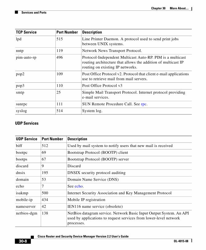
Chapter 30 More About....Services and Ports
UDP Services
lpd 515 Line Printer Daemon. A protocol used to send print jobs between UNIX systems.
nntp 119 Network News Transport Protocol.
pim-auto-rp 496 Protocol-Independent Multicast Auto-RP. PIM is a multicast routing architecture that allows the addition of multicast IP routing on existing IP networks.
pop2 109 Post Office Protocol v2. Protocol that client e-mail applications use to retrieve mail from mail servers.
pop3 110 Post Office Protocol v3
smtp 25 Simple Mail Transport Protocol. Internet protocol providing e-mail services.
sunrpc 111 SUN Remote Procedure Call. See rpc.
syslog 514 System log.
UDP Service Port Number Description
biff 512 Used by mail system to notify users that new mail is received
bootpc 69 Bootstrap Protocol (BOOTP) client
bootps 67 Bootstrap Protocol (BOOTP) server
discard 9 Discard
dnsix 195 DNSIX security protocol auditing
domain 53 Domain Name Service (DNS)
echo 7 See echo.
isakmp 500 Internet Security Association and Key Management Protocol
mobile-ip 434 Mobile IP registration
nameserver 42 IEN116 name service (obsolete)
netbios-dgm 138 NetBios datagram service. Network Basic Input Output System. An API used by applications to request services from lower-level network processes.
TCP Service Port Number Description
30-8Cisco Router and Security Device Manager Version 2.2 User’s Guide
OL-4015-08

Chapter 30 More About....Services and Ports
netbios-ns 137 NetBios name service
netbios-ss 139 NetBios session service
ntp 123 Network Time Protocol. TCP protocol that ensures accurate local timekeeping with reference to radio and atomic clocks located on the Internet.
pim-auto-rp 496 Protocol Independent Multicast, reverse path flooding, dense mode
rip 520 Routing Information Protocol. A protocol used to exchange route information between routers.
snmp 161 Simple Network Management Protocol. A protocol used to monitor and control network devices.
snmptrap 162 SNMP trap. A system management notification of some event that occurred on the remotely managed system.
sunrpc 111 SUN Remote Procedure Call. RPCs are procedure calls that are built or specified by clients and executed on servers, with the results returned over the network to the client.
syslog 514 System log service.
tacacs 49 Terminal Access Controller Access Control System. Authentication protocol that provides remote access authentication and related services, such as logging.
talk 517 Talk. A protocol originally intended for communication between teletype terminals, but now a rendezvous port from which a TCP connection can be established.
tftp 69 Trivial File Transfer Protocol. Simplified version of FTP that allows files to be transferred between network nodes.
time 37 Time.
who 513 Port to databases showing who is logged in to machines on a local net and the load average of the machine
xdmcp 177 X-Display Manager Client Protocol. A protocol used for communications between X-Displays (clients) and X Display Managers.
non500-isakmp
4500 Internet Security Association and Key Management Protocol. This keyword is used when NAT-traversal port floating is required.
UDP Service Port Number Description
30-9Cisco Router and Security Device Manager Version 2.2 User’s Guide
OL-4015-08

Chapter 30 More About....Services and Ports
ICMP Message Types
ICMP Messages Port Number Description
alternate-address 6 Alternate host address.
conversion-error 31 Sent to report a datagram conversion error.
echo 8 Type of message sent when ping command is issued.
echo-reply 0 Response to an echo-request (ping) message.
information-reply 16 Obsolete. Response to message sent by host to discover number of the network it is on. Replaced by DHCP.
information-request 15 Obsolete. Message sent by host to discover number of the network it is on. Replaced by DHCP.
mask-reply 18 Response to message sent by host to discover network mask for the network it is on.
mask-request 17 Obsolete. Message sent by host to discover network mask for the network it is on.
mobile-redirect 32 Mobile host redirect. Sent to inform a mobile host of a better first-hop node on the path to a destination.
parameter-problem 12 Message generated in response to packet with problem in its header.
redirect 5 Sent to inform a host of a better first-hop node on the path to a destination.
router-advertisement 9 Sent out periodically, or in response to a router solicitation.
router-solicitation 10 Messages sent in order to prompt routers to generate router advertisements messages quickly.
source-quench 4 Sent when insufficient buffer space is available to queue packets for transmission to next hop, or by destination router when packets are arriving too quickly to be processed.
time-exceeded 11 Sent to indicate received packet’t time to live field has reached zero.
timestamp-reply 14 Reply to request for timestamp to be used for synchronization between two devices.
30-10Cisco Router and Security Device Manager Version 2.2 User’s Guide
OL-4015-08

Chapter 30 More About....Services and Ports
IP Services
timestamp-request 13 Request for timestamp to be used for synchronization between two devices.
traceroute 30 Message sent in reply to a host that has issued a traceroute request.
unreachable 3 Destination unreachable. Packet cannot be delivered for reasons other than congestion.
IP Services Port Number Description
aahp 51
eigrp 88 Enhanced Interior Gateway Routing Protocol. Advanced version of IGRP developed by Cisco.
esp 50 Extended Services Processor.
icmp 1 Internet Control Message Protocol. Network layer protocol that reports errors and provides other information relevant to IP packet processing.
igmp 2 Internet Group Management Protocol. Used by IP hosts to report their multicast group memberships to adjacent multicast routers.
ip 0 Internet Protocol. Network layer protocol offering connectionless internetwork service.
ipinip 4 IP-in-IP encapsulation.
nos 94 network operating system. A distributed file system protocol.
ospf 89 Open Shortest Path First. A link-state hierarchical routing algorithm.
pcp 108 Payload Compression Protocol
pim 103 Protocol-Independent Multicast. PIM is a multicast routing architecture that allows the addition of multicast IP routing on existing IP networks.
ICMP Messages Port Number Description
30-11Cisco Router and Security Device Manager Version 2.2 User’s Guide
OL-4015-08

Chapter 30 More About....Services and Ports
Services That Can Be Specified in Inspection Rules
tcp 6 Transmission Control Protocol. Connection-oriented transport layer protocol that provides reliable full-duplex data transmission.
udp 17 User Datagram Protocol. Connectionless transport layer protocol in the TCP/IP protocol stack.
Protocol Description
cuseeme Videoconferencing protocol.
fragment Specifies that the rule perform fragment inspection.
ftp See ftp.
h323 See H.323.
http See HTTP, HTTPS.
icmp See icmp.
netshow NetShow. A streaming video protocol.
rcmd Remote Comman d. A protocol used when commands are executed on a remote system by a local system.
realaudio RealAudio. A streaming audio protocol.
rpc Remote Procedure Call. RPCs are procedure calls that are built or specified by clients and executed on servers, with the results returned over the network to the client
rtsp Real-Time Streaming Protocol. An application-level protocol used to control delivery of data with real-time properties.
sip Session Initiation Protocol. Sip is a telephony protocol used to integrate telephony services and data services.
skinny A telephony protocol enabling telephony clients to be H.323 compliant.
smtp See smtp.
sqlnet Protocol for network enabled databases.
streamworks StreamWorks protocol. Streaming video protocol.
IP Services Port Number Description
30-12Cisco Router and Security Device Manager Version 2.2 User’s Guide
OL-4015-08

Chapter 30 More About....More About NAT
More About NATThis section provides scenario information that may help you in completing the NAT Translation Rule windows, and other information that explains why NAT rules created using the CLI may not be editable in SDM.
Static Address Translation ScenariosThe following scenarios show you how you can use the static address translation rules.
Scenario 1
You need to map an IP address for a single host to a public address. The address of the host is 10.12.12.3. The public address is 172.17.4.8.
The following table shows how the fields in the Add Address Translation Rule window would be used.
Result
The source address 10.12.12.3 is translated to the address 172.17.4.8 in packets leaving the router. If this is the only NAT rule for this network, 10.12.12.3 is the only address on the network that gets translated.
tcp See tcp.
tftp See tftp.
udp See udp.
vdolive VDOLive protocol. A streaming video protocol.
Protocol Description
Static/Dynamic
Translate from Interface Fields Translate to Interface Fields
IP Address Net Mask IP Address Redirect Port
Static 10.12.12.3 Leave blank 172.17.4.8 Leave unchecked.
30-13Cisco Router and Security Device Manager Version 2.2 User’s Guide
OL-4015-08

Chapter 30 More About....More About NAT
Scenario 2
You need to map each IP address in a network to a unique public IP address, and you do not want to create a separate rule for each mapping. The source network number is 10.l2.12.0, and the target network is 172.17.4.0. However, in this scenario, it is not necessary to know the source or target network numbers. It is sufficient to enter host addresses and a network mask.
The following table shows how the fields in the Add Address Translation Rule window would be used.
Result
NAT derives the “Translate from” network address from the host IP address and the subnet mask. NAT derives the “Translate to” network address from the the net mask entered in the “Translate from” fields, and the “Translate to” IP address. The source IP address in any packet leaving the original network is translated to an address in the 172.17.4.0 network.
Scenario 3
You want to use the same global IP address for several hosts on the trusted network. Inbound traffic will contain a different port number based on the destination host.
The following table shows how the fields in the Add Address Translation Rule window would be used.
Static/Dynamic
Translate from Interface Fields Translate to Interface Fields
IP Address Net Mask IP Address Redirect Port
Static 10.12.12.35 (host) 255.255.255.0 172.17.4.8 (host) Leave unchecked.
Static/Dynamic
Translate from... fields Translate to... fields
IP Address Net Mask IP Address Redirect Port
Static 10.12.12.3 Leave blank 172.17.4.8 UDP
Original Port 137
Translated Port 139
30-14Cisco Router and Security Device Manager Version 2.2 User’s Guide
OL-4015-08
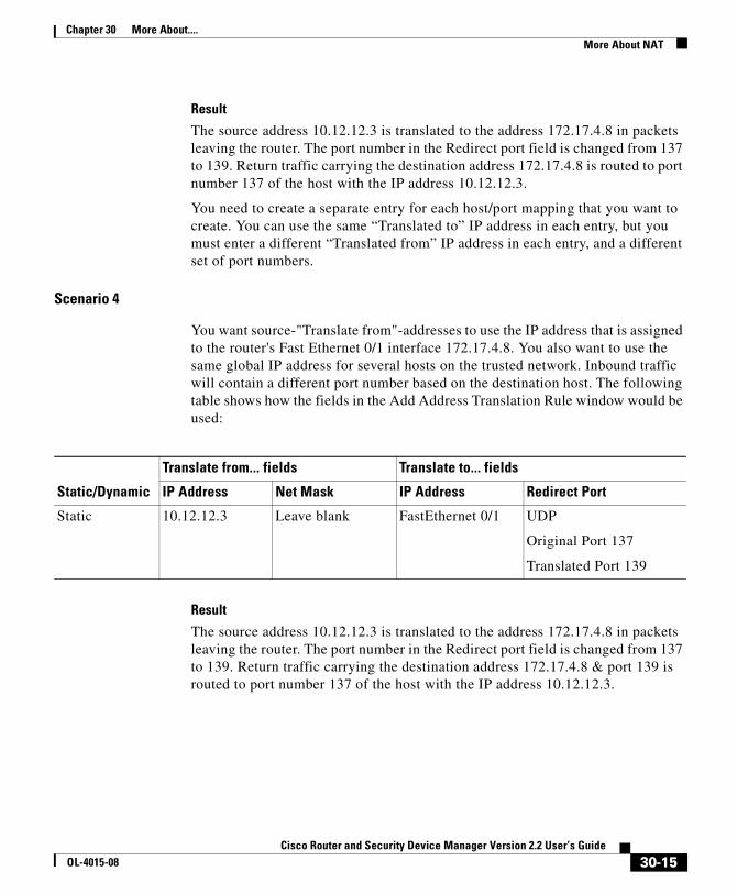
Chapter 30 More About....More About NAT
Result
The source address 10.12.12.3 is translated to the address 172.17.4.8 in packets leaving the router. The port number in the Redirect port field is changed from 137 to 139. Return traffic carrying the destination address 172.17.4.8 is routed to port number 137 of the host with the IP address 10.12.12.3.
You need to create a separate entry for each host/port mapping that you want to create. You can use the same “Translated to” IP address in each entry, but you must enter a different “Translated from” IP address in each entry, and a different set of port numbers.
Scenario 4
You want source-"Translate from"-addresses to use the IP address that is assigned to the router's Fast Ethernet 0/1 interface 172.17.4.8. You also want to use the same global IP address for several hosts on the trusted network. Inbound traffic will contain a different port number based on the destination host. The following table shows how the fields in the Add Address Translation Rule window would be used:
Result
The source address 10.12.12.3 is translated to the address 172.17.4.8 in packets leaving the router. The port number in the Redirect port field is changed from 137 to 139. Return traffic carrying the destination address 172.17.4.8 & port 139 is routed to port number 137 of the host with the IP address 10.12.12.3.
Static/Dynamic
Translate from... fields Translate to... fields
IP Address Net Mask IP Address Redirect Port
Static 10.12.12.3 Leave blank FastEthernet 0/1 UDP
Original Port 137
Translated Port 139
30-15Cisco Router and Security Device Manager Version 2.2 User’s Guide
OL-4015-08
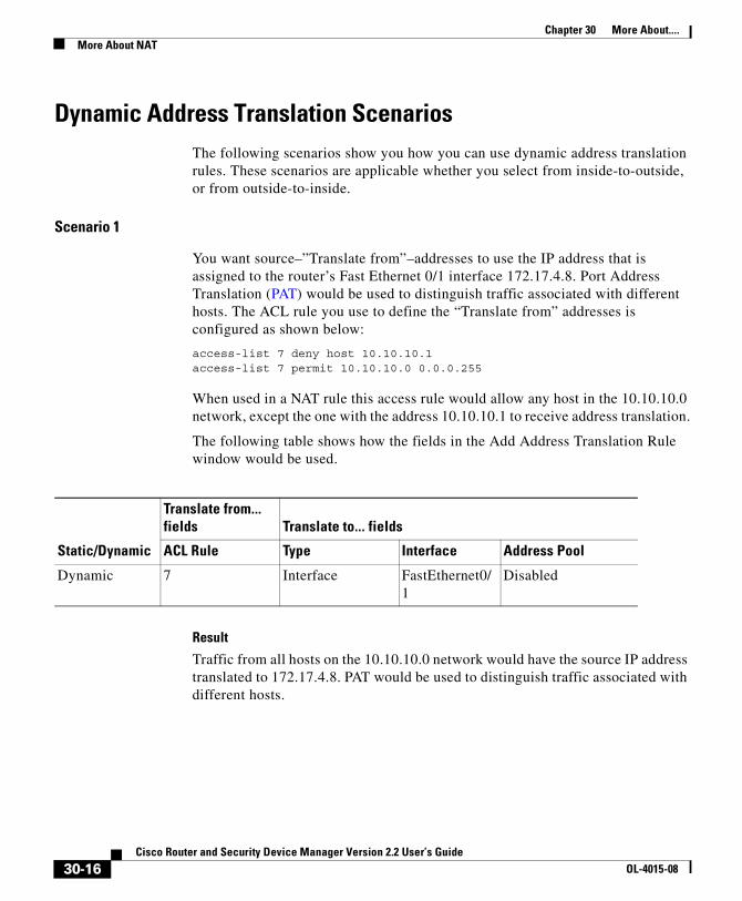
Chapter 30 More About....More About NAT
Dynamic Address Translation ScenariosThe following scenarios show you how you can use dynamic address translation rules. These scenarios are applicable whether you select from inside-to-outside, or from outside-to-inside.
Scenario 1
You want source–”Translate from”–addresses to use the IP address that is assigned to the router’s Fast Ethernet 0/1 interface 172.17.4.8. Port Address Translation (PAT) would be used to distinguish traffic associated with different hosts. The ACL rule you use to define the “Translate from” addresses is configured as shown below:
access-list 7 deny host 10.10.10.1access-list 7 permit 10.10.10.0 0.0.0.255
When used in a NAT rule this access rule would allow any host in the 10.10.10.0 network, except the one with the address 10.10.10.1 to receive address translation.
The following table shows how the fields in the Add Address Translation Rule window would be used.
Result
Traffic from all hosts on the 10.10.10.0 network would have the source IP address translated to 172.17.4.8. PAT would be used to distinguish traffic associated with different hosts.
Static/Dynamic
Translate from... fields Translate to... fields
ACL Rule Type Interface Address Pool
Dynamic 7 Interface FastEthernet0/1
Disabled
30-16Cisco Router and Security Device Manager Version 2.2 User’s Guide
OL-4015-08
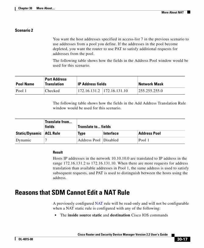
Chapter 30 More About....More About NAT
Scenario 2
You want the host addresses specified in access-list 7 in the previous scenario to use addresses from a pool you define. If the addresses in the pool become depleted, you want the router to use PAT to satisfy additional requests for addresses from the pool.
The following table shows how the fields in the Address Pool window would be used for this scenario.
The following table shows how the fields in the Add Address Translation Rule window would be used for this scenario.
Result
Hosts IP addresses in the network 10.10.10.0 are translated to IP address in the range 172.16.131.2 to 172.16.131.10. When there are more requests for address translation than available addresses in Pool 1, the same address is used to satisfy subsequent requests, and PAT is used to distinguish between the hosts using the address.
Reasons that SDM Cannot Edit a NAT RuleA previously configured NAT rule will be read-only and will not be configurable when a NAT static rule is configured with any of the following:
• The inside source static and destination Cisco IOS commands
Pool NamePort Address Translation IP Address fields Network Mask
Pool 1 Checked 172.16.131.2 172.16.131.10 255.255.255.0
Static/Dynamic
Translate from... fields Translate to... fields
ACL Rule Type Interface Address Pool
Dynamic 7 Address Pool Disabled Pool 1
30-17Cisco Router and Security Device Manager Version 2.2 User’s Guide
OL-4015-08
Chapter 30 More About....More About VPN
• The inside source static network command with one of the keywords “extendable”, “no-alias”, or “no-payload”
• The outside source static network command with one of the keywords “extendable”, “no-alias”, or “no-payload”
• The inside source static tcp command with one of the keywords “no-alias” or “no-payload”
• The inside source static udp command with one of the keywords “no-alias” or “no-payload”
• The outside source static tcp command with one of the keywords “no-alias” or “no-payload”
• The outside source static udp command with one of the keywords “no-alias” or “no-payload”
• The inside source static command with one of the keywords “no-alias”, “no-payload”, “extendable”, “redundancy”, “route-map”, or “vrf”
• The outside source static command with one of the keywords “no-alias”, “no-payload”, “extendable”, or “add-route”
• The inside source static command with the keyword “esp”
• The inside source static command with the interface command
A NAT dynamic rule is configured with the Loopback interface
More About VPNThese topics contain more information about VPN, DMVPN, IPSec and IKE.
Cisco.com ResourcesThe following links provide TAC resources and other information on VPN issues.
• How Virtual Private Networks Work
• Dynamic Multipoint IPSec VPNs
• TAC-authored articles on IPSec
• TAC-authored articles on SDM
30-18Cisco Router and Security Device Manager Version 2.2 User’s Guide
OL-4015-08

Chapter 30 More About....More About VPN
• Security and VPN Devices
• IPSecurity Troubleshooting–Understanding and Using Debug Commands
• Field Notices
More about VPN Connections and IPSec PoliciesA VPN connection is an association between a router interface and an IPSec policy. The building block of an IPSec policy is the crypto map. A crypto map specifies the following: a transform set and other parameters to govern encryption, the identity of one or more peers, and an IPSec rule that specifies which traffic will be encrypted. An IPSec policy can contain multiple crypto maps.
The following diagram shows an interface (ATM 3/1.1) associated with an IPSec policy. The policy has three crypto maps, each specifying a different peer system. The ATM 3/1.1 interface is thus associated with three VPN connections.
A crypto map can specify more than one peer for a connection. This may be done to provide redundancy. The following diagram shows the same interface and policy, but crypto map CM-3 specifies two peers: Topeka and Lawrence.
8843
3ATM3/1.1
Crypto Map 1
Policy 5
Crypto Map 2
Crypto Map 3
Seattle
Chicago
Topeka
30-19Cisco Router and Security Device Manager Version 2.2 User’s Guide
OL-4015-08

Chapter 30 More About....More About VPN
A router interface can be associated with only one IPSec policy. However, an IPSec policy can be associated with multiple router interfaces, and a crypto map can specify more than one peer for a connection. The following diagram shows two router interfaces associated with a policy, and a crypto map specifying two peers.
There are six VPN connections in this configuration, as both Dialer 3 and Serial 1/1 have connections to Seattle, Chicago, Topeka, and Lawrence. SDM would show the links to Topeka and Lawrence as one connection for both interfaces.
8843
4
ATM3/1.1
Crypto Map 1
Policy 5
Crypto Map 2
Crypto Map 3
Seattle
Chicago
Topeka
Lawrence
8843
5
Dialer3Crypto Map 1
Policy 5
Crypto Map 2
Crypto Map 3
Seattle
Chicago
Topeka
Lawrence
Serial1/1
30-20Cisco Router and Security Device Manager Version 2.2 User’s Guide
OL-4015-08
Chapter 30 More About....More About VPN
More About IKEIKE handles the following tasks:
• Authentication
• Session Negotiation
• Key Exchange
• IPSec Tunnel Negotiation and Configuration
Authentication
Authentication is arguably the most important task that IKE accomplishes, and it certainly is the most complicated. Whenever you negotiate something, it is of utmost importance that you know with whom you are negotiating. IKE can use one of several methods to authenticate negotiating parties to each other.
• Pre-shared Key. IKE uses a hashing technique to ensure that only someone who possesses the same key could have sent the IKE packets.
• DSS or RSA digital signatures. IKE uses public-key digital-signature cryptography to verify that each party is whom he or she claims to be.
• RSA encryption. IKE uses one of two methods to encrypt enough of the negotiation to ensure that only a party with the correct private key could continue the negotiation.
Note SDM supports the pre-shared key method of authentication.
Session Negotiation
During session negotiation, IKE allows parties to negotiate how they will conduct authentication and how they will protect any future negotiations (that is, IPSec tunnel negotiation). The following items are negotiated:
• Authentication Method. This is one of the authentication methods listed above.
• Key Exchange Algorithm. This is a mathematical technique for securely exchanging cryptographic keys over a public medium (that is, Diffie-Hellman). The keys are used in the encryption and packet-signature algorithms.
30-21Cisco Router and Security Device Manager Version 2.2 User’s Guide
OL-4015-08

Chapter 30 More About....More About VPN
– Encryption Algorithm: DES, 3DES, or AES
– Packet Signature Algorithm: MD5 or SHA-1
Key Exchange
IKE uses the negotiated key-exchange method (see “Session Negotiation” above) to create enough bits of cryptographic keying material to secure future transactions. This method ensures that each IKE session will be protected with a new, secure set of keys.
Authentication, session negotiation, and key exchange constitute phase 1 of an IKE negotiation.
IPSec Tunnel Negotiation and Configuration
After IKE has finished negotiating a secure method for exchanging information (phase 1), we use IKE to negotiate an IPSec tunnel. This is accomplished in IKE phase 2. In this exchange, IKE creates fresh keying material for the IPSec tunnel to use (either using the IKE phase 1 keys as a base or by performing a new key exchange). The encryption and authentication algorithms for this tunnel are also negotiated.
More About IKE PoliciesWhen the IKE negotiation begins, IKE looks for an IKE policy that is the same on both peers. The peer that initiates the negotiation will send all its policies to the remote peer, and the remote peer will try to find a match. The remote peer looks for a match by comparing its own highest priority policy against the other peer’s received policies. The remote peer checks each of its policies in order of its priority (highest first) until a match is found.
A match is made when both policies from the two peers contain the same encryption, hash, authentication, and Diffie-Hellman parameter values, and when the remote peer’s policy specifies a lifetime less than or equal to the lifetime in the policy being compared. If the lifetimes are not identical, the shorter lifetime-from the remote peer’s policy will be used.
30-22Cisco Router and Security Device Manager Version 2.2 User’s Guide
OL-4015-08

Chapter 30 More About....More About VPN
Allowable Transform CombinationsTo define a transform set, you specify one to three transforms. Each transform represents an IPSec security protocol (AH or ESP) plus the algorithm that you want to use. When the particular transform set is used during negotiations for IPSec security associations, the entire transform set (the combination of protocols, algorithms, and other settings) must match a transform set at the remote peer.
The following table lists the acceptable transform combination selections for the AH and ESP protocols.
The following table describes each of the transforms.
AH Transform(Pick up to one)
ESP Encryption Transform(Pick up to one)
Authentication Transform(Pick up to one)
IP Compression Transform(Pick up to one)
Examples(Total of 3 transforms allowed)
ah-md5-hmac
ah-sha-hmac
esp-des
esp-3des
esp-null
es-aes-128
esp-aes-192
esp-aes-256
esp-seal
esp-md5-hmac
esp-sha-hmac
comp-lzs 1. ah-md5-hmac
2. esp-3des and esp-md5-hmac
3. ah-sha-hmac, esp-des, and esp-sha-hmac
Transform Description
ah-md5-hmac AH with the MD5 (HMAC variant) authentication algorithm.
ah-sha-hmac AH with the SHA (HMAC variant) authentication algorithm.
esp-des ESP with the 56-bit DES encryption algorithm.
esp-3des ESP with the 168-bit DES encryption algorithm (3DES or Triple DES)
esp-null Null encryption algorithm.
esp-seal ESP with the 160-bit encryption key Software Encryption Algorithm (SEAL) encryption algorithm.
30-23Cisco Router and Security Device Manager Version 2.2 User’s Guide
OL-4015-08

Chapter 30 More About....Reasons Why a Serial Interface or Subinterface Configuration May Be Read-Only
Examples
The following are examples of permissible transform combinations:
• ah-md5-hmac
• esp-des
• esp-3des and esp-md5-hmac
• ah-sha-hmac, esp-des, and esp-sha-hmac
• comp-lzs
Reasons Why a Serial Interface or Subinterface Configuration May Be Read-Only
A previously configured Serial interface or subinterface will be read-only and will not be configurable in the following cases:
• The interface is configured with the encapsulation ppp and ppp multilink ... Cisco IOS commands.
• The interface is configured with the encapsulation hdlc and ip address negotiated commands.
• The interface is part of a SERIAL_CSUDSU_56K WIC.
• The interface is part of a Sync/Async WIC configured with the physical-layer async command.
esp-md5-hmac ESP with the MD5 (HMAC variant) authentication algorithm.
es-aes-128 ESP with Advanced Encryption Standard (AES). Encryption with a 128-bit key
esp-aes-192 ESP with AES. Encryption with a 192-bit key.
esp-aes-256 ESP with AES. Encryption with a 256-bit key.
esp-sha-hmac ESP with the SHA (HMAC variant) authentication algorithm.
comp-lzs IP compression with the LZS algorithm.
Transform Description
30-24Cisco Router and Security Device Manager Version 2.2 User’s Guide
OL-4015-08

Chapter 30 More About....Reasons Why an ATM Interface or Subinterface Configuration May Be Read-Only
• The interface is configured with the encapsulation frame-relay command with an IP address on the main interface.
• The interface encapsulation is not “hdlc,” “ppp,” or “frame-relay.”
• The encapsulation frame-relay ... command contains the mfr ... option.
• The interface is configured with the encapsulation ppp command, but the PPP configuration contains unsupported commands.
• The interface is configured with the encapsulation frame-relay and frame-relay map ... commands.
• The main interface is configured with the encapsulation frame-relay and frame-relay interface-dlci ... commands.
• The main interface is configured with the encapsulation frame-relay command and the subinterface is configured with the frame-relay priority-dlci-group ... command.
• The subinterface is configured with the interface-dlci ... command that contains any of the keywords “ppp,” “protocol,” or “switched.”
• The subinterface type is “multipoint,” instead of “point-to-point.”
• The subinterface is configured with any encapsulation other than “frame-relay.”
Reasons Why an ATM Interface or Subinterface Configuration May Be Read-Only
A previously configured ATM interface or subinterface will be read-only and will not be configurable in the following cases:
• It has a PVC with the dialer pool-member command.
• It has a PVC in which the protocol specified in the protocol command is not ip.
• It has a PVC with multiple protocol ip commands.
• The encapsulation on the PVC is neither “aal5mux,” nor “aal5snap.”
• If the encapsulation protocol on aal5mux is not “ip.”
• If the IP Address is not configured on the PVC in the protocol ip command.
30-25Cisco Router and Security Device Manager Version 2.2 User’s Guide
OL-4015-08
Chapter 30 More About....Reasons Why an Ethernet Interface Configuration May Be Read-Only
• If the “dial-on-demand” option is configured on the pppoe-client command.
• If there is more than 1 PVC configured on the interface.
• If the encapsulation on the associated dialer is blank or is not “ppp.”
• If no IP address is configured on the associated dialer.
• If VPDN is required (which is determined dynamically from the Cisco IOS image) but is not configured for this connection.
• If the operating mode is “CO” on an SHDSL interface (ATM main interfaces only).
• If no IP address is configured on the interface and the interface is not configured for PPPoE (ATM subinterfaces only).
• The interface has an IP address but no associated PVC.
• The interface has a PVC but no associated IP address and is not configured for PPPoE.
• The bridge-group command is configured on the interface.
• If the main interface has one or move PVCs as well as one or more subinterfaces.
• If the main interface is not configurable (ATM subinterfaces only).
• It is a multipoint interface (ATM subinterfaces only).
Reasons Why an Ethernet Interface Configuration May Be Read-Only
A previously configured Ethernet LAN or WAN interface or will be read-only and will not be configurable in the following cases:
• If the LAN interface has been configured as a DHCP server, and has been configured with an IP-helper address.
30-26Cisco Router and Security Device Manager Version 2.2 User’s Guide
OL-4015-08

Chapter 30 More About....Reasons Why an ISDN BRI Interface Configuration May Be Read-Only
Reasons Why an ISDN BRI Interface Configuration May Be Read-Only
A previously configured ISDN BRI interface will be read-only and will not be configurable in the following cases:
• An IP address is assigned to the ISDN BRI interface.
• Encapsulation other than ppp is configured on the ISDN BRI interface.
• The dialer-group or dialer string command is configured on the ISDN BRI interface.
• dialer pool-member <x> is configured on the ISDN BRI interface, but the corresponding dialer interface <x> is not present.
• Multiple dialer pool-members are configured on the ISDN BRI interface.
• The dialer map command is configured on the ISDN BRI interface.
• Encapsulation other than ppp is configured on the dialer interface.
• Either dialer-group or dialer-pool is not configured on the dialer interface.
• dialer-group <x> is configured on the dialer interface, but the corresponding dialer -list <x> protocol command is not configured.
• dialer idle-timeout <num> with optional keyword (either/inbound) is configured on the dialer interface.
• dialer string command with optional keyword class is configured on the dialer interface.
• If using the ISDN BRI connection as a backup connection, once the backup configuration is through SDM, if any of the conditions below occur, the backup connection will be shown as read only:
– The default route through the primary interface is removed
– The backup interface default route is not configured
– ip local policy is removed
– track /rtr or both is not configured
– route-map is removed
– Access-list is removed or access-list is modified (for example, tracking ip address is modified)
30-27Cisco Router and Security Device Manager Version 2.2 User’s Guide
OL-4015-08

Chapter 30 More About....Reasons Why an Analog Modem Interface Configuration May Be Read-Only
– The SDM-supported interfaces are configured with unsupported configurations
– The primary interfaces are not supported by SDM
Reasons Why an Analog Modem Interface Configuration May Be Read-Only
A previously configured analog modem interface or will be read-only and will not be configurable in the following cases:
• An IP address is assigned to the asynchronous interface.
• Encapsulation other than ppp is configured on the asynchronous interface.
• The dialer-group or dialer string command is configured on the asynchronous interface.
• Async mode interactive is configured on the asynchronous interface.
• dialer pool-member <x> is configured on the asynchronous interface, but the corresponding dialer interface <x> is not present.
• Multiple dialer pool-members are configured on the asynchronous interface.
• Encapsulation other than ppp is configured on the dialer interface.
• Either dialer-group or dialer-pool is not configured on the dialer interface.
• dialer-group <x> is configured on the dialer interface, but the corresponding dialer -list <x> protocol command is not configured.
• dialer idle-timeout <num> with optional keyword (either/inbound) is configured on the dialer interface.
• In line configuration collection mode, modem inout is not configured.
• In line configuration collection mode, autoselect ppp is not configured.
• If using the analog modem connection as a backup connection, once the backup configuration is through SDM, if any of the conditions below occur, the backup connection will be shown as read only:
– The default route through the primary interface is removed
– The backup interface default route is not configured
– ip local policy is removed
30-28Cisco Router and Security Device Manager Version 2.2 User’s Guide
OL-4015-08

Chapter 30 More About....Firewall Policy Use Case Scenario
– track /rtr or both is not configured
– route-map is removed
– Access-list is removed or access-list is modified (for example, tracking ip address is modified)
– The SDM-supported interfaces are configured with unsupported configurations
– The primary interfaces are not supported by SDM
Firewall Policy Use Case ScenarioIn this scenario, a firewall and DMZ network have been created using the SDM Firewall wizard. The user has added a webserver to the DMZ network, and needs to allow web traffic into the DMZ network.
These are the interfaces used in this scenario:
• Inside interface: Fast Ethernet 0/0
• Outside interface: Serial 1/0
• DMZ interface: Fast Ethernet 1/0
The following sections show how to use the Firewall Policy window to examine the rules applied to router interfaces with the Firewall wizard or Rules windows and how to modify access and inspection rules.
• Examining Originating Traffic: From Interface Fast Ethernet 0/0; To Interface Serial 1/0
• Examining Returning Traffic: From Interface Ethernet 0/0; To Interface Serial 1/0
• Examining Originating Traffic: From: Serial 1/0; To: Ethernet 1/0
• Allowing www Traffic to DMZ Interface.
30-29Cisco Router and Security Device Manager Version 2.2 User’s Guide
OL-4015-08

Chapter 30 More About....Firewall Policy Use Case Scenario
Examining Originating Traffic: From Interface Fast Ethernet 0/0; To Interface Serial 1/0
In this configuration, there is a firewall filtering traffic entering the router on the Serial 1/0 interface bound for the network connected to the Fast Ethernet 0/0 interface. The following traffic diagram shows that an access rule and an inspection rule have been applied to inbound traffic on the Fast Ethernet 0/0 interface, and that an access rule has been applied to inbound traffic on Serial 1/0.
In this diagram, the firewall icon indicates that a firewall is active between Fast Ethernet 0/0 and Serial 1/0. This is based on the presence of the inspection rule applied to Fast Ethernet 0/0, and the access rule applied to inbound traffic on Serial 1/0. Although an access rule has been applied to Fast Ethernet 0/0, it is not necessary for the firewall.
The following illustration shows entries for the inspection rule on Fast Ethernet 0/0.
These entries specify which traffic inbound on Fast Ethernet 0/0 will be inspected as it enters the router. Returning traffic matching the inspection criteria will be allowed into the router if it is associated with a session initiated on Fast Ethernet 0/0’s network.
Examining Returning Traffic: From Interface Ethernet 0/0; To Interface Serial 1/0
Clicking the Returning traffic button displays the access rule for inbound traffic on Serial 1/0.
30-30Cisco Router and Security Device Manager Version 2.2 User’s Guide
OL-4015-08

Chapter 30 More About....Firewall Policy Use Case Scenario
These are the entries that protect the network attached to Fast Ethernet 0/0. The Deny entries filter IP traffic from specific networks. There is an explicit permit all entry for IP traffic, and two Permit entries for ICMP traffic bound for specific hosts.
The Applications area would still display the inspection rule applied to Fast Ethernet 0/0 inbound, even though returning traffic was selected.
Examining Originating Traffic: From: Serial 1/0; To: Ethernet 1/0
In order to view the policy for traffic bound for the DMZ interface, the user can select Swap From and To interfaces from the View Options menu, and select Fast Ethernet 1/0 in the To interface list. Doing so makes Serial 1/0 the From interface and Fast Ethernet 1/0 the To interface.
30-31Cisco Router and Security Device Manager Version 2.2 User’s Guide
OL-4015-08

Chapter 30 More About....DMVPN Configuration Recommendations
The Services area shows that certain types of ICMP traffic have been permitted.
Allowing www Traffic to DMZ Interface
The method shown in this section can also be used when there is no DMZ network, but you want to allow a certain type of traffic onto your trusted network.
In order to allow www traffic to the hosts 10.10.10.1 and 10.10.10.2 in the DMZ network, the user creates 2 entries using the Add button. In the Add an Extended Rule Entry dialog, the destination host IP addresses are specified, the TCP protocol is chosen, the source port any is chosen, and the destination port www is chosen. The two new permit entries are the second and third entries from the last entry.
DMVPN Configuration RecommendationsThis help topic contains recommendations on how you should proceed when configuring routers in a DMVPN.
Configure the Hub First
It is important to configure the hub first because spokes must be configured using information about the hub. If you are configuring a hub, you can use the Spoke Configuration feature available in the Summary window to generate a text file that contains a procedure that you can send to spoke administrators so that they can configure the spokes with the correct hub information. If you are configuring a spoke, you must obtain the correct information about the hub before you begin.
30-32Cisco Router and Security Device Manager Version 2.2 User’s Guide
OL-4015-08

Chapter 30 More About....DMVPN Configuration Recommendations
Assigning Spoke Addresses
All routers in the DMVPN must be in the same subnet. Therefore, the hub administrator must assign addresses in the subnet to the spoke routers so that address conflicts do not occur, and so that everyone is using the same subnet mask.
Recommendations for Configuring Routing Protocols for DMVPN
The following are guidelines that you should note when configuring routing protocols for DMVPN. You can choose to ignore these guidelines, but SDM has not been tested in scenarios outside the guidelines and may not be able to let you edit configurations within SDM after you enter them.
These recommendations are listed in best-choice order:
• If a routing process exists that advertises inside networks, use this process to advertise networks to the DMVPN.
• If a routing process exists that advertises tunnel networks for VPNs, for example GRE over IPSec tunnels, use this process to advertise the DMVPN networks.
• If a routing process exists that advertises networks for the WAN interfaces, then be sure to use an AS number or process ID that the WAN interfaces do not use to advertise networks.
• When you configure DMVPN routing information SDM checks whether the Autonomous System number (EIGRP) or area ID (OSPF) you enter is already used to advertise networks for the router’s physical interface. If the value is already in use, SDM informs you of this and recommends that you either use a new value, or that you select a different routing protocol to advertise networks on the DMVPN.
Using Interfaces with Dialup Configurations
Selecting an interface that uses a dialup connection may cause the connection to be always up. You can examine supported interfaces in Interfaces and Connections to determine if a dialup connection, such as an ISDN or Async connection has been configured for the physical interface you selected.
30-33Cisco Router and Security Device Manager Version 2.2 User’s Guide
OL-4015-08

Chapter 30 More About....SDM White Papers
Ping the Hub Before You Start Spoke Configuration
Before configuring a spoke router, you should test connectivity to the hub by issuing the ping command. If the ping does not succeed, you must configure a route to the hub.
SDM White PapersA number of white papers are available that describe how SDM can be used. These white papers are available at the following link.
http://www.cisco.com/univercd/cc/td/doc/product/software/sdm/appnote/index.htm
30-34Cisco Router and Security Device Manager Version 2.2 User’s Guide
OL-4015-08

Cisco Router and Security DeOL-4015-08
C H A P T E R31
Getting StartedCisco Router and Security Device Manager (SDM) is an easy-to-use Internet browser-based software tool designed for configuring LAN, WAN, and security features on a router. SDM is designed for resellers and network administrators of small- to medium-sized businesses who are proficient in LAN fundamentals and basic network design.
For fast and efficient configuration of Ethernet networks, WAN connectivity, firewalls and Virtual Private Networks (VPNs), SDM prompts you through the setup process with wizards—sequenced screens that break down the configuration steps and provide you with explanatory text. You can then edit the basic configuration you created, for greater control over the router and the network. SDM requires no previous experience with Cisco devices or the Cisco command-line interface (CLI).
When you start SDM, it displays the Home Page, a window with system and configuration overview information that gives you important information about your router hardware and software. You can use this to determine what you want to configure. After you complete a configuration, SDM can help you test and troubleshoot it so that you can ensure that the configuration works.
SDM also features a Monitor mode, which enables you to observe router performance and gather statistics associated with configurations that you have made on the router.
31-1vice Manager Version 2.2 User’s Guide
Chapter 31 Getting StartedWhat’s New in this Release?
What’s New in this Release?To find out the new features SDM supports, go to:
http://www.cisco.com/go/sdm
Click the Technical Documentation link, and then click Release Notes.
Cisco IOS Versions SupportedTo determine which Cisco IOS versions SDM supports, go to the following URL:
http://www.cisco.com/go/sdm
Click the Technical Documentation link, and then click Release Notes.
31-2Cisco Router and Security Device Manager Version 2.2 User’s Guide
OL-4015-08

Cisco Router and Security DeOL-4015-08
C H A P T E R32
Viewing Router InformationThe Cisco Router and Security Device Manager (SDM) Monitor mode lets you view a current snapshot of information about your router, the router interfaces, the firewall, and any active VPN connections. You can also view any messages in the router event log.
Note The Monitor window is not dynamically updated with the latest information. To view any information that has changed since you brought up this window, you must click Update.
Monitor mode works by examining the router log and by viewing the results of Cisco IOS show commands. For Monitor mode functions that are based on log entries, such as firewall statistics, logging must be enabled. Logging is enabled by default by SDM, but you can change that setting using the Additional Tasks>Router Properties>Logging window. In addition, individual rules may need configuration so that they generate log events. For more information, see the help topic How Do I View Activity on My Firewall?
32-1vice Manager Version 2.2 User’s Guide

Chapter 32 Viewing Router InformationOverview
OverviewThe Monitor mode Overview screen displays an overview of your router activity and statistics, and serves as a summary of the information contained on the other Monitor mode screens. It contains the information described in this help topic.
Note If you do not see feature information described in this help topic on the Overview screen, the Cisco IOS image does not support the feature. For example, if the router is running a Cisco IOS image that does not support security features, the Firewall Status, and VPN status sections do not appear on the screen.
Update Button
Retrieves current information from the router, updating statistics displayed by this screen.
If you want to: Do this:
View information about router interfaces.
From the toolbar, click Monitor, and then in the left frame, click Interface Status. From the Select Interface field select the interface for which you want to view information, then in the Available Items group, select the information you want to view. Then click Show Details.
View graphs of CPU or memory usage. From the toolbar, click Monitor. The Overview page includes graphs of CPU usage and memory usage.
View information about the firewall. From the toolbar, click Monitor, and then in the left frame, click Firewall Status.
View information about VPN Connections
From the toolbar, click Monitor, and then in the left frame, click VPN Status. Then select the tab for IPSec Tunnels, DMVPN Tunnels, Easy VPN Servers, or IKE SAs.
View messages in the router event log. From the toolbar, click Monitor, and then in the left frame, click Logging.
32-2Cisco Router and Security Device Manager Version 2.2 User’s Guide
OL-4015-08
Chapter 32 Viewing Router InformationOverview
Resource Status
Shows basic information about your router hardware and contains the following fields:
CPU Usage
Shows the percentage of CPU usage.
Memory Usage
Shows the percent of RAM usage.
Flash Usage
Shows the available flash over the amount of flash installed on the router.
Interface Status
Shows basic information about the interfaces installed on the router and their status.
Note Only interface types supported by SDM are included in these statistics. Unsupported interfaces will not be counted.
Total Interface(s) Up
The total number of enabled (up) interfaces on the router.
Total Interface(s) Down
The total number of disabled (down) interfaces on the router.
Interface
The interface name.
IP
The IP address of the interface.
Status
The status of the interface, either Up, or Down.
32-3Cisco Router and Security Device Manager Version 2.2 User’s Guide
OL-4015-08
Chapter 32 Viewing Router InformationOverview
Bandwidth Usage
The percent of interface bandwidth being used.
Description
Available description for the interface. SDM may add descriptions such as $FW_OUTSIDE$ or $ETH_LAN$.
Firewall Status Group
Shows basic information about the router resources and contains the following fields:
Number of Attempts Denied
Shows the number of log messages generated by connection attempts (by protocols such as Telnet, HTTP, HTTPS, ping, and others) rejected by the firewall. Note that in order for a log entry to be generated by a rejected connection attempt, the access rule that rejected the connection attempt must be configured to create log entries.
Firewall Log
If enabled, shows the number of firewall log entries.
QoS
The number of interfaces with an associated QoS policy.
VPN Status Group
Shows basic information about the router resources and contains the following fields:
Number of Open IKE SAs
Shows the number of IKE Security Associations (SAs) connections currently configured and running.
Number of Open IPSec Tunnels
Shows the number of IPSec Virtual Private Network (VPN) connections currently configured and running.
32-4Cisco Router and Security Device Manager Version 2.2 User’s Guide
OL-4015-08

Chapter 32 Viewing Router InformationOverview
No. of DMVPN Clients
If the router is configured as a DMVPN hub, the number of DMVPN clients.
No. of Active VPN Clients
If the router is configured as an EasyVPN Server, this field shows the number of Easy VPN Remote clients.
NAC Status Group
Shows a basic snapshot of Network Admission Control (NAC) status on the router.
No. of NAC enabled interfaces field
The number of router interfaces on which NAC is enabled.
No. of validated hosts field
The number of hosts with posture agents that have been validated by the admissions control process.
Log Group
Shows basic information about the router resources and contains the following fields:
Total Log Entries
The total number of entries currently stored in the router log.
High Severity
The number of log entries stored that have a severity level of 2 or lower. These messages require immediate attention. Note that this list will be empty if you have no high severity messages.
Warning
The number of log entries stored that have a severity level of 3 or 4. These messages may indicate a problem with your network, but they do not likely require immediate attention.
32-5Cisco Router and Security Device Manager Version 2.2 User’s Guide
OL-4015-08

Chapter 32 Viewing Router InformationInterface Status
Informational
The number of log entries stored that have a severity level of 6 or higher. These information messages signal normal network events.
Interface StatusThe Interface Status screen displays the current status of the various interfaces on the router, and the numbers of packets, bytes, or data errors that have travelled through the selected interface. Statistics shown on this screen are cumulative since the last time the router was rebooted, the counters were reset, or the selected interface reset.
Monitor Interface and Stop Monitoring Button
Click this button to start or stop monitoring the selected interface. The button label changes based on whether SDM is monitoring the interface or not.
Test Connection Button
Click to test the selected connection. A dialog appears that enables you to specify a remote host to ping through this connection. The dialog then reports on the success or failure of the test. If the test fails, information about why the test may have failed is given, along with the steps you need to take to correct the problem.
Interface List
Select the interface for which you want to display statistics from this list. The list contains the name, IP address and subnet mask, the slot and port it is located in, and any SDM or user description entered.
Select Chart Types to Monitor Group
These check boxes are the data items for which SDM can show statistics on the selected interface. These data items are as follows:
• Packet Input—The number of packets received on the interface.
• Packet Output—The number of packets sent by the interface.
32-6Cisco Router and Security Device Manager Version 2.2 User’s Guide
OL-4015-08
Chapter 32 Viewing Router InformationInterface Status
• Bandwidth Usage—The percent of bandwidth used by the interface, shown as a percentage value. Here is how bandwidth percentage is computed:
Bandwidth percentage=(Kbps/bw) * 100,
where
bits per second= ((change in input+change in output) * 8) / poll interval
Kbps= bits per second/1024
bw=bandwidth capacity of the interface
Because the differences in bytes input and bytes output can only be computed after the second view interval, the bandwidth percentage graph shows the correct bandwidthe usage starting with the second view interval. See the View Interval section of this topic for polling intervals and view intervals.
• Bytes Input—The number of bytes received on the interface.
• Bytes Output—The number of bytes sent by the interface.
• Input Errors—The number of errors occurring while receiving data on the interface.
• Output Errors—The number of errors occurring while sending data from the interface.
To view statistics for any of these items:
Step 1 Select the item(s) you want to view by checking the associated check box(es).
Step 2 Click Monitor Interface to see statistics for all selected data items.
Interface Status Area
View Interval
This pull-down field selects both the amount of data shown for each item and the frequency with which the data is updated. It has the following options
Note The polling frequencies listed are approximations and may differ slightly from the listed times.
32-7Cisco Router and Security Device Manager Version 2.2 User’s Guide
OL-4015-08
Chapter 32 Viewing Router InformationVPN Status
• Real-time data every 10 sec. This option will continue polling the router for a maximum of two hours, resulting in approximately 120 data points.
• 10 minutes of data polled every 10 sec.
• 60 minutes of data, polled every 1 minute.
• 12 hours of data, polled every 10 minutes.
Note The last three options will retrieve a maximum of 60 data points. After 60 data points have been retrieved, SDM will continue to poll data, replacing the oldest data points with the newest ones.
Show Table/Hide Table
Click this button to show or hide the performance charts.
Reset button
Click this button to reset the interface statistic counts to zero.
Chart Area
This area shows the charts and simple numerical values for the data specified.
Note The last three options will retrieve a maximum of 30 data points. After 30 data points have been retrieved, SDM will continue to poll data, replacing the oldest data points with the newest ones.
VPN StatusThis screen displays statistics about the VPN connections that are active on the router.
Select a Category
From this pull-down field, select the type of VPN for which you want to see statistics. The statistics corresponding to the selection made in this field will appear in the field below. You can select one of the following VPN categories:
32-8Cisco Router and Security Device Manager Version 2.2 User’s Guide
OL-4015-08

Chapter 32 Viewing Router InformationVPN Status
• IPSec Tunnels
• DMVPN Tunnels
• Easy VPN Servers
• IKE SAs
Test Tunnel.. Button
Click to test a selected VPN tunnel.The results of the test will be shown in another window.
IPSec Tunnels
This group displays statistics about each IPSec VPN that is configured on the router. Each row in the table represents one IPSec VPN. The columns in the table and the information they display are as follows:
• Interface column
The WAN interface on the router on which the IPSec tunnel is active.
• Local IP column
The IP address of the local IPSec interface.
• Remote IP column
The IP address of the remote IPSec interface.
• Peer column
The IP address of the remote peer.
• Tunnel Status
The current status of the IPSec tunnel. Possible values are:
– Up—The tunnel is active
– Down—The tunnel is inactive due to an error or hardware failure.
• Encapsulation Packets column
The number of packets encapsulated over the IPSec VPN connection.
• Decapsulation Packets column
The number of packets decapsulated over the IPSec VPN connection.
• Send Error Packets column
32-9Cisco Router and Security Device Manager Version 2.2 User’s Guide
OL-4015-08
Chapter 32 Viewing Router InformationVPN Status
The number of errors that have occurred while sending packets.
• Receive Error Packets column
The number of errors that have occurred while receiving packets.
• Encrypted Packets column
The number of packets encrypted over the connection.
• Decrypted Packets column
The number of packets decrypted over the connection.
• Update button
Click this button to refresh the IPSec Tunnel table and display the most current data from the router.
• Clear button
Select a row in the table, and click Clear to clear the IPSec tunnel connection.
DMVPN Tunnels
This group displays the following statistics about Dynamic Multi-point VPN (DMVPN) tunnels. Each row reflects one VPN tunnel.
• Remote Subnet column
The network address of the subnet to which the tunnel connects.
• Remote Tunnel IP column
The IP address of the remote tunnel. This is the private IP address given the tunnel by the remote device.
• IP Public Interface of Remote Router column
IP address of the public (outside) interface of the remote router.
• Expiration column
The time and date when the tunnel registration expires and the DMVPN tunnel will be shut down.
• Status column
The status of the DMVPN tunnel.
• Reset button
32-10Cisco Router and Security Device Manager Version 2.2 User’s Guide
OL-4015-08
Chapter 32 Viewing Router InformationVPN Status
Resets statistics counters for the tunnel listed, setting number of packets encapsulated and decaspsulated, number of sent and received errors, and number of packets encrypted and decrypted to zero.
Easy VPN Servers
This group displays the following information about each Easy VPN Server group:
• Total number of server clients (in upper right corner)
• Group Name
• Number of client connections
Group Details Button
Clicking Group Details shows the following information about the selected group.
• Group Name
• Key
• Pool Name
• DNS Servers
• WINS Servers
• Domain Name
• ACL
• Backup Servers
• Firewall-R-U-There
• Include local LAN
• Group lock
• Save password
• Maximum connections allowed for this group
• Maximum logins per user
Client Connections in this Group
This area shows the following information about the selected group.
32-11Cisco Router and Security Device Manager Version 2.2 User’s Guide
OL-4015-08

Chapter 32 Viewing Router InformationVPN Status
• Public IP address
• Assigned IP address
• Encrypted Packets
• Decrypted Packets
• Dropped Outbound Packets
• Dropped Inbound Packets
• Status
Update button
Click this button to display the most current data from the router.
Disconnect button
• Choose a row in the table and click Disconnect to drop the connection with the client.
IKE SAs
This group displays the following statistics about each active IKE security association configured on the router:
• Source IP column
The IP address of the peer originating the IKE SA.
• Destination IP column
The IP address of the remote IKE peer.
• State column
Describes the current state of IKE negotiations. The following states are possible:
– MM_NO_STATE—The Internet Security Association and Key Management Protocol (ISAKMP) SA has been created but nothing else has happened yet.
– MM_SA_SETUP—The peers have agreed on parameters for the ISAKMP SA.
32-12Cisco Router and Security Device Manager Version 2.2 User’s Guide
OL-4015-08

Chapter 32 Viewing Router InformationFirewall Status
– MM_KEY_EXCH—The peers have exchanged Diffie-Hellman public keys and have generated a shared secret. The ISAKMP SA remains unauthenticated.
– MM_KEY_AUTH—The ISAKMP SA has been authenticated. If the router initiated this exchange, this state transitions immediately to QM_IDLE and a Quick mode exchange begins.
– AG_NO_STATE—The ISAKMP SA has been created but nothing else has happened yet.
– AG_INIT_EXCH—The peers have done the first exchange in Aggressive mode but the SA is not authenticated.
– AG_AUTH—The ISAKMP SA has been authenticated. If the router initiated this exchange, this state transitions immediately to QM_IDLE and a Quick mode exchange begins.
– QM_IDLE—The ISAKMP SA is idle. It remains authenticated with its peer and may be used for subsequent Quick mode exchanges.
• Update button—Click this button to refresh the IKE SA table and display the most current data from the router.
• Clear button—Select a row in the table and click Clear to clear the IKE SA connection.
Firewall StatusThis Firewall Status page displays the following statistics about the firewall configured on the router. The statistics and log entries shown in this screen are determined by log messages generated by the firewall. In order for the firewall to generate log entries, you must configure individual access rules to generate log messages when they are invoked. For instructions on configuring access rules to cause log messages, see the help topic How Do I View Activity on My Firewall?
Firewall Log
Whether or not the router is configured to maintain a log of connection attempts allowed and denied by the firewall.
32-13Cisco Router and Security Device Manager Version 2.2 User’s Guide
OL-4015-08

Chapter 32 Viewing Router InformationFirewall Status
Number of Attempts Denied by Firewall
Shows the number of connection attempts rejected by the firewall.
Attempts Denied by Firewall Table
Shows a list of connection attempts denied by the firewall. This table includes the following columns:
• Time column
Shows the time that each denied connection attempt occurred.
• Description column
Contains the following information about the denied attempt: log name, access rule name or number, service, source address, destination address, and number of packets. An example follows:
%SEC-6-IPACCESSLOGDP: list 100 denied icmp 171.71.225.148->10.77.158.140 (0/0), 3 packets
Update Button
Polls the router and updates the information shown on the screen with current information.
Monitoring Firewall with an non-Administrator view user account
Firewall monitoring requires that logging buffered be enabled on the router. If logging buffered is not enabled, login to SDM using an Administrator view account or using a non-view based privilege level 15 user account and configure logging.
To configure logging in SDM, go to Additional Tasks > Router Properties > Logging.
Application Security LogIf logging has been enabled, and you have specified that alarms be generated when the router encounters traffic from applications or protocols that you have specified, those alarms are collected in a log that can be viewed from this window. The following is example log text for instant messenging applications:
32-14Cisco Router and Security Device Manager Version 2.2 User’s Guide
OL-4015-08

Chapter 32 Viewing Router InformationNAC Status
*Jun 27 11:42:01.323: %APPFW-6-IM_MSN_SESSION: im-msn text-chat service session initiator 14.1.0.1:1973 sends 142 bytes to responder 207.46.108.33:1863*Jun 28 11:42:01.323: %APPFW-6-IM_MSN_SESSION: im-msn un-recognized service session initiator 14.1.0.1:2000 sends 1364 bytes to responder 207.46.108.19:1863*Jun 29 11:42:01.323: %APPFW-6-IM_YAHOO_SESSION: im-yahoo text-chat service session initiator 14.1.0.1:2009 sends 100 bytes to responder 216.155.193.184:5050*Jun 20 11:42:01.323: %APPFW-6-IM_YAHOO_SESSION: im-yahoo un-recognized service session initiator 14.1.0.1:2009 sends 100 bytes to responder 216.155.193.184:5050*Jun 21 11:42:01.323: %APPFW-6-IM_AOL_SESSION: im-aol text-chat service session initiator 14.1.0.1:2009 sends 100 bytes to responder 216.155.193.184:5050*Jun 22 11:42:01.323: %APPFW-6-IM_AOL_SESSION: im-aol un-recognized service session initiator 14.1.0.1:2009 sends 100 bytes to responder 216.155.193.184:5050*Jun 23 11:42:01.323: %APPFW-4-HTTP_PORT_MISUSE_IM: Sig:10006 HTTP Instant Messenger detected - Reset - Yahoo Messenger from 10.10.10.2:1332 to 216.155.194.191:80*Jun 24 11:42:06.227: %APPFW-4-HTTP_PORT_MISUSE_IM: Sig:10006 HTTP Instant Messenger detected - Reset - Yahoo Messenger from 10.10.10.2:1333 to 216.155.194.191:80*Jun 25 11:42:10.959: %APPFW-4-HTTP_PORT_MISUSE_IM: Sig:10006 HTTP Instant Messenger detected - Reset - Yahoo Messenger from 10.10.10.2:1334 to 216.155.194.191:80
NAC StatusIf NAC is configured on the router, SDM can display snapshot information about the NAC sessions on the router, the interfaces on which NAC is configured, and NAC statistics for the selected interface.
The top row in the window displays the number of active NAC sessions, the number of NAC sessions being initalized, and a button that allows you to clear all active and initializing NAC sessions
The window lists the router interfaces with associated NAC policies.
FastEthernet0/0 10.10.15.1/255.255.255.0 0
32-15Cisco Router and Security Device Manager Version 2.2 User’s Guide
OL-4015-08

Chapter 32 Viewing Router InformationNAC Status
Clicking on an interface entry displays the information returned by posture agents installed on the hosts in the subnet for that interface. An example of the interface information follows:
10.10.10.5 Remote EAP Policy Infected 12
10.10.10.1 is the host’s IP address. Remote EAP Policy is the type of authentication policy that is in force. The host’s current posture is Infected, and it has been 12 minutes since the host completed the admissions control process.
Note This area of the window contains no data if no posture information is returned by the hosts on the selected subnet.
The authentication types are:
• Local Exception Policy—An exception policy that is configured on the router is used to validate the host.
• Remote EAP Policy—The host returns a posture, and an exception policy assigned by an ACS server is used.
• Remote Generic Access Policy—The host does not have a posture agent installed, and the ACS server assigns an agentless host policy.
The posture agents on the hosts may return the following posture tokens:
• Healthy—The host is free of known viruses, and has the latest virus definition files.
• Checkup—The posture agent is determining if the latest virus definition files have been installed.
• Quarantine—The host does not have the latest virus definition files installed. The user is redirected to the specified remediation site that contains instructions for downloading the latest virus definition files.
• Infected—The host is infected with a known virus. The user is redirected to a remediation site to obtain virus definition file updates.
• Unknown—The host’s posture is unknown.
32-16Cisco Router and Security Device Manager Version 2.2 User’s Guide
OL-4015-08

Chapter 32 Viewing Router InformationLogging
LoggingThe router contains a log of events categorized by severity level, like a UNIX syslog service. This screen displays the router log. Note that it is the router log that is displayed, even if log messages are being forwarded to a syslog server.
Logging Buffer
Shows whether or not the logging buffer and syslog logging are enabled. The text “Enabled” is displayed when both are enabled. The logging buffer reserves a specified amount of memory to retain log messages. The setting in this field is not preserved if your router is rebooted. The default settings for these fields are for the logging buffer to be enabled with 4096 bytes of memory.
Logging Hosts
Shows the IP address of any syslog hosts where log messages are being forwarded. This field is read-only. To configure the IP addresses of syslog hosts, use the Additional Tasks>Router Properties>Logging window.
Logging Level (Buffer)
Shows the logging level configured for the buffer on the router.
Number of Messages in Log
Shows the total number of messages stored in the router log.
Select a Logging Level to View
From this field, select the severity level of the messages that you want to view in the log. Changing the setting in this field causes the list of log messages to be refreshed.
Log
Displays all messages with the severity level specified in the Select a Logging Level to View field. Log events contains the following information:
• Severity Column
32-17Cisco Router and Security Device Manager Version 2.2 User’s Guide
OL-4015-08
Chapter 32 Viewing Router InformationLogging
Shows the severity of the logging event. Severity is shown as a number from 1 through 7, with lower numbers indicating more severe events. The descriptions of each of the severity levels are as follows:
– 0 - emergencies
System unusable
– 1- alerts
Immediate action needed
– 2 - critical
Critical conditions
– 3 - errors
Error conditions
– 4 - warnings
Warning conditions
– 5 - notifications
Normal but significant condition
– 6 - informational
Informational messages only
– 7 - debugging
Debugging messages
• Time Column
Shows the time that the log event occurred.
• Description Column
Shows a description of the log event.
Update
Updates the screen with current information about log details and the most current log entries.
Clear
Erases all messages from the log buffer on the router.
32-18Cisco Router and Security Device Manager Version 2.2 User’s Guide
OL-4015-08

Chapter 32 Viewing Router InformationLogging
32-19Cisco Router and Security Device Manager Version 2.2 User’s Guide
OL-4015-08

Chapter 32 Viewing Router InformationLogging
32-20Cisco Router and Security Device Manager Version 2.2 User’s Guide
OL-4015-08

Cisco Router and Security DeOL-4015-08
C H A P T E R33
File Menu CommandsThe following options are available from the Cisco Router and Security Device Manager (SDM) File menu.
Save Running Config to PCSaves the router’s running configuration file to a text file on the PC.
Deliver Configuration to RouterThis window lets you deliver to the router any configuration changes that you have made using SDM. Note that any changes to the configuration that you made using SDM will not affect the router until you deliver the configuration.
Save Running Config to Router’s Startup Config
Check this check box to cause SDM to save the configuration shown in the window to both the router running configuration file and the startup file. The running configuration file is temporary—it is erased when the router is rebooted. Saving the configuration to the router startup configuration causes the configuration changes to be retained after a reboot.
If SDM is being used to configure a Cisco 7000 router, the check box Save running config. to router's startup config. will be disabled if there are boot network or boot host commands present with service config commands in the running configuration.
33-1vice Manager Version 2.2 User’s Guide

Chapter 33 File Menu CommandsWrite to Startup Config
Cancel
Click this button to discard the configuration change and close the SDM Deliver to Router dialog box.
Save to File
Click this button to save the configuration changes shown in the window to a text file.
Write to Startup ConfigWrites the router’s running configuration file to the router startup configuration.
If SDM is being used to configure a Cisco 7000 router, this menu item will be disabled if there are boot network or boot host commands present with service config commands in the running configuration.
Reset to Factory DefaultsSee Resetting to Factory Defaults.
File ManagementThis window allows you to view and manage the file system on your Cisco router flash memory and on USB flash devices connected to that router. Only DOSFS file systems can be viewed and managed in this window.
The left side of window displays an expandible tree representing the directory system on your Cisco router flash memory and on USB flash devices connected to that router.
The right side of the window displays a list of the names of the files and directories found in the directory that is chosen in the left side of the window. It also shows the size of each file in bytes, and the date and time each file and directory was last modified.
33-2Cisco Router and Security Device Manager Version 2.2 User’s Guide
OL-4015-08

Chapter 33 File Menu CommandsFile Management
You can choose a file or directory in the list on the right side of the window and then choose one of the commands above the list. Directories can be renamed or deleted. Files can be copied, pasted, renamed, or deleted, but files cannot be pasted into the directory from which they were copied. Files with the no-write icon next to their names cannot be copied, pasted, renamed, or deleted.
Refresh Button
Click the Refresh button to fetch a new image of the directories and files from your Cisco router flash memory and from USB flash devices connected to that router.
Format Button
Click the Format button to reformat your Cisco router flash memory or to reformat a USB flash device connected to that router. The Format button is enabled only if an icon representing your Cisco router flash memory or a USB flash device is chosen in the left side of the window.
Caution Reformatting your Cisco router flash memory or a USB flash device connected to that router will erase all of the files in the file system.
New Folder Button
Click the New Folder button to create a new directory in the directory that is chosen in the left side of the window.
Load File From PC Button
Click the Load File From PC button to open a file-selection window on the local PC. Choose a file to save to the chosen directory on your Cisco router flash memory or on a USB flash device connected to that router.
Copy Button
Choose a file from the right side of the window and click the Copy button to copy the file.
33-3Cisco Router and Security Device Manager Version 2.2 User’s Guide
OL-4015-08

Chapter 33 File Menu CommandsFile Management
Paste Button
After you click the Copy button to copy a file, click the Paste button to place the copy of the file in a different directory. Choose a target directory from the left side of the window. You cannot place a copy of the file in the same directory as the original file.
Rename Button
Choose a file or directory from the right side of the window and click the Rename button to change its name.
Delete Button
Choose a file or directory from the right side of the window and click the Delete button to delete it. A file with the no-write icon next to its name cannot be deleted.
Filename
Click Filename to order the files and directories alphabetically based on name. Clicking Filename again will reverse the order.
Size
Click Size to order the files and directories by size. Directories always have a size of zero bytes, even if they are not empty. Clicking Size again will reverse the order.
Time Modified
Click Time Modified to order the files and directories based on modification date and time. Clicking Time Modified again will reverse the order.
RenameThis window allows you to rename a file on your Cisco router flash memory or on USB flash devices connected to that router.
Enter the new filename in the New Name field. The path to the location of the file is displayed above the New Name field.
33-4Cisco Router and Security Device Manager Version 2.2 User’s Guide
OL-4015-08

Chapter 33 File Menu CommandsSave SDF to PC
New FolderThis window allows you to name and create a new folder in the directory system on your Cisco router flash memory and on USB flash devices connected to that router.
Enter the name of the new folder in the Folder Name field. The path to the location of the new folder is displayed above the Folder Name field.
Save SDF to PCIf you are working in IPS, you can save the signature definition file (SDF) that you are working on to your PC. Navigate to the directory in which you want to save the file, and click Save.
ExitExits Cisco Router and Security Device Manager.
Unable to perform ‘squeeze flash’This window appears when your router is unable to perform a squeeze flash operation because an erase flash: operation has never been performed on the router. This help topic explains how to download the files you need before performing the erase flash: operation, how to execute erase flash:, and how to load files back onto the router and reconnect to SDM afterward.
Executing the erase flash: command will remove SDM and the Cisco IOS image from the router's Flash, Flash memory, and you will lose your connection to the router. You should print the contents of this help topic so that you can use the instructions to obtain a Cisco IOS image and SDM.tar from Cisco.com, and install them on the router.
Step 1 Ensure that the router will not lose power. If the router loses power after an erase flash: operation, there will be no Cisco IOS image in memory.
33-5Cisco Router and Security Device Manager Version 2.2 User’s Guide
OL-4015-08
Chapter 33 File Menu CommandsUnable to perform ‘squeeze flash’
Note If the router does lose power after the erase flash operation, you can use the procedure at the following link to recover: http://www.cisco.com/univercd/cc/td/doc/product/access/acs_mod/cis3700/sw_conf/37_swcf/appendc.htm#xtocid11
Step 2 Save the router’s running configuration to a file on the PC by clicking File > Save Running Config to PC, and entering a filename.
Step 3 Prepare a TFTP server to which you can save files and copy them over to the router. You must have write access to the TFTP server. Your PC can be used for this purpose if it has a TFTP server program.
Step 4 Use the tftpcopy command to copy the Cisco IOS image, the SDM.tar file, and the SDM.shtml file from Flash memory to a TFTP server:
copy flash: tftp://tftp-server-address/filename
Example:
copy flash: tftp://10.10.10.3/SDM.tar
Note If you prefer to download a Cisco IOS image, the SDM.tar file, and the SDM.shtml file, follow these instructions to use an Internet connection to download an SDM-supported Cisco IOS image, the SDM.tar file, and the SDM.shtml file. Then place those files on a TFTP server.
a. Click the following link to obtain a Cisco IOS image from the Cisco Software Center:
http://www.cisco.com/kobayashi/sw-center/
b. Obtain an image that supports the features you want on the 12.2(11)T release or later. Save the file to the TFTP server that is accessible from the router.
c. Use the following link to obtain the SDM.tar and SDM.shtml files. Then save SDM.tar and SDM.shtml to the TFTP server.
http://www.cisco.com/go/sdm
Step 5 From the PC, log on to the router using Telnet, and enter Enable mode.
33-6Cisco Router and Security Device Manager Version 2.2 User’s Guide
OL-4015-08
Chapter 33 File Menu CommandsUnable to perform ‘squeeze flash’
Step 6 Enter the command erase flash:, and confirm. The router's IOS image, configuration file, the SDM.tar file, and the SDM.shtml file are removed from non-volatile RAM (NVRAM).
Step 7 Use the tftpcopy command to first copy the IOS image and then SDM.tar from the TFTP server to the router:
copy tftp://tftp-server-address/filename flash:
Example:
copy tftp://10.10.10.3/ios_image_name flash:! Replace ios_image_name with actual name of IOS imagecopy tftp://10.10.10.3/SDM.tar flash:
Step 8 Start your web browser, and reconnect to SDM, using the same IP address you used when you started the SDM session.
Now that an erase flash: has been performed on the router, you will be able to execute the squeeze flash command when necessary.
33-7Cisco Router and Security Device Manager Version 2.2 User’s Guide
OL-4015-08

Chapter 33 File Menu CommandsUnable to perform ‘squeeze flash’
33-8Cisco Router and Security Device Manager Version 2.2 User’s Guide
OL-4015-08

Cisco Router and Security DeOL-4015-08
C H A P T E R34
Edit Menu CommandsThe following options are available from the Cisco Router and Security Device Manager (SDM) Edit menu.
PreferencesThis screen lets you configure the following Cisco Router and Security Device Manager options:
Preview commands before delivering to router
Choose this option if you want SDM to display a list of the Cisco IOS configuration commands generated before the commands are sent to the router.
Save signature file to Flash
Choose this option if you want the signature definition file (SDF) that you are working on to be saved to router flash when you click Apply Changes.
Confirm before exiting SDM
This is SDM default behavior. Select this option if you would like SDM to display a dialog box asking for confirmation when you exit SDM.
34-9vice Manager Version 2.2 User’s Guide

Chapter 34 Edit Menu CommandsPreferences
Continue monitoring interface status when switching mode/task
This is SDM default behavior. SDM begins monitoring interface status when you click Monitor and select Interface status. To have SDM continue monitoring the interface even if you leave Monitor mode and perform other tasks in SDM, select this check box and specify the maximum number of interfaces you want SDM to monitor. The default maximum number of interfaces to monitor is 4.
34-10Cisco Router and Security Device Manager Version 2.2 User’s Guide
OL-4015-08

Cisco Router and Security DeOL-4015-08
C H A P T E R35
View Menu CommandsThe following options are available from the Cisco Router and Security Device Manager (SDM) View menu.
HomeDisplays the SDM Home page which provides information about router hardware, software, and LAN, WAN, Firewall, and VPN configurations.
ConfigureDisplays the SDM Tasks bar, which allows you to perform guided and manual configurations for Interfaces and Connections, Firewalls and ACLs, VPNs Routing, and other tasks.
MonitorDisplays the SDM Monitor window, which lets you view statistics about your router and network.
35-1vice Manager Version 2.2 User’s Guide

Chapter 35 View Menu CommandsRunning Config
Running ConfigDisplays the router’s running configuration.
Show CommandsDisplays the Show Commands dialog box, which lets you issue Cisco IOS show commands to the router and view the output. The Show Commands dialog box can display the output from the following show commands:
• show flash—Shows the contents of the router Flash memory.
• show startup-config—Shows the router startup configuration file.
• show access-lists—Shows all of the Access Control Lists (ACLs) commands currently configured on the router.
• show diag—Shows information about the hardware installed in the router.
• show interfaces—Shows information about the configuration of each interface and about the packets transferred over the interface.
• show protocols—Shows information about the network protocols configured on each interface.
• show version—Shows information about the version of Cisco IOS software running on the router.
SDM Default RulesThe SDM Default Rules screen displays a list of all of the default rules configured by SDM. The screen is organized with a tree on the left side of the screen displaying options for Access Rules, Firewall, VPN - IKE Policy, and VPN - Transform Sets. To view the default rules for these options, click the option in the tree, and the default rules for that option are displayed on the right. For more information about the rules, see the option descriptions that follow.
35-2Cisco Router and Security Device Manager Version 2.2 User’s Guide
OL-4015-08

Chapter 35 View Menu CommandsRefresh
Access Rules
Shows all of the default Access Control List (ACL) rules that permit or deny traffic to the network.
Firewall
Shows a list of protocols and the default options for whether each of them triggers an alert and an audit trail.
VPN - IKE Policy
Shows the default Internet Key Exchange (IKE) policies.
VPN - Transform Sets
Shows the default IP Security (IPSec) transform sets.
RefreshReloads configuration information from the router. If there are any undelivered commands, SDM displays a message window telling you that if you refresh, you will lose undelivered commands. If you want to deliver the commands. click No in this window, and then click Deliver on the SDM toolbar.
35-3Cisco Router and Security Device Manager Version 2.2 User’s Guide
OL-4015-08

Chapter 35 View Menu CommandsRefresh
35-4Cisco Router and Security Device Manager Version 2.2 User’s Guide
OL-4015-08
Cisco Router and Security DeOL-4015-08
C H A P T E R36
Tools Menu CommandsThe following options are available from the Cisco Router and Security Device Manager (SDM) Tools menu.
PingDisplays the Ping dialog box, which lets you send a ping message to another network device. See Generate Mirror... for information on how to use the Ping window.
TelnetDisplays the Windows Telnet dialog box, letting you connect to your router and access the Cisco IOS command-line interface (CLI) using the Telnet protocol.
Security AuditDisplays the SDM Security Audit screen. See Security Audit for more information.
36-1vice Manager Version 2.2 User’s Guide
Chapter 36 Tools Menu CommandsUSB Token PIN Settings
USB Token PIN SettingsThe USB Token PIN Settings dialog box allows you to set PINs for USB tokens connected to your router.
Select a PIN Type
Choose User PIN to set a user PIN, or Admin PIN to set an administrator PIN.
A user PIN is used to log into a router. If you connect a USB token to a router, and the token’s name and user PIN match an entry in Configure > VPN > VPN Components > Public Key Infrastructure > USB Tokens, you are automatically logged into that router.
An administrator PIN is used to manage USB token settings using the manufacturer’s software. SDM allows you to change the administrator PIN for a USB token if you can supply the current administrator PIN.
Token Name
Enter the USB token’s name.
The token’s name is set by the manufacturer. For example, USB tokens manufactured by Aladdin Knowledge Systems are named eToken.
You can also use the name “usbtokenx”, where x is the number of the USB port to which the USB token is connected. For example, a USB token connected to USB port 0 is named usbtoken0.
Current PIN
Enter the existing user or administrator PIN. If you do not know the existing PIN, you must use the USB token manufacturer’s software to find it.
New PIN
Enter a new PIN for the USB token. The existing PIN will be replaced by the new PIN. The new PIN must be at least 4 digits long.
Confirm PIN
Reenter the new PIN to confirm it.
36-2Cisco Router and Security Device Manager Version 2.2 User’s Guide
OL-4015-08

Chapter 36 Tools Menu CommandsUpdate SDM
Save the New PIN to Router
Check the Save the new PIN to router checkbox if you want to save the new PIN as an entry in Configure > VPN > VPN Components > Public Key Infrastructure > USB Tokens. If an entry with the same name already exists in Configure > VPN > VPN Components > Public Key Infrastructure > USB Tokens, it is replaced with the new one.
The Save the new PIN to router checkbox is available only for user PINs.
Update SDMYou can have SDM obtain and install an update automatically.
Update SDM from Cisco.com
You can update SDM directly from Cisco.com. SDM checks Cisco.com for the versions available and informs you if there is a version newer than the one currently running on the router. You can then update SDM using the Update wizard.
To update SDM from Cisco.com:
Step 1 Select Update SDM from Cisco.com from the Tools menu. Selecting this option starts the update wizard.
Step 2 Use the update wizard to obtain the SDM files and copy them to your router.
Update SDM from Local PC
You can update SDM using an SDM.zip file you have downloaded from Cisco.com. SDM provides an update wizard that will copy the necessary files to your router.
To update SDM from the PC you are using to run SDM follow these steps:
Step 1 Download the file sdm-vnn.zip from the following URL:
http://www.cisco.com/cgi-bin/tablebuild.pl/sdm
36-3Cisco Router and Security Device Manager Version 2.2 User’s Guide
OL-4015-08
Chapter 36 Tools Menu CommandsUpdate SDM
If there is more than one SDM .zip file, obtain the copy with the highest version number.
Step 2 Use the update wizard to copy the SDM files from your PC to the router.
36-4Cisco Router and Security Device Manager Version 2.2 User’s Guide
OL-4015-08

Chapter 36 Tools Menu CommandsUpdate SDM
Update SDM from CD
If you have the SDM CD, you can use it to update SDM on your router. To do so, follow these steps:
Step 1 Place the SDM CD in the CD drive on your PC.
Step 2 Select Update SDM from CD, and click Update SDM in the General Instructions window after reading the text.
Step 3 SDM will enable you to locate the file SDM-Updates.xml on the CD. When you locate the file, click Open.
Step 4 Follow the instructions in the installation wizard.
36-5Cisco Router and Security Device Manager Version 2.2 User’s Guide
OL-4015-08

Chapter 36 Tools Menu CommandsUpdate SDM
36-6Cisco Router and Security Device Manager Version 2.2 User’s Guide
OL-4015-08

Cisco Router and Security DeOL-4015-08
C H A P T E R37
Help Menu CommandsThe following options are available from the Cisco Router and Security Device Manager (SDM) Help menu.
Help TopicsDisplays the SDM online help. The SDM online help Table of Contents appears in the left frame of the help.
SDM on CCOOpens up a browser and displays the SDM page on the Cisco.com website.
About this router...Displays hardware and software information about the router on which SDM is running.
About SDMDisplays version information about SDM.
37-1vice Manager Version 2.2 User’s Guide

Chapter 37 Help Menu CommandsAbout SDM
37-2Cisco Router and Security Device Manager Version 2.2 User’s Guide
OL-4015-08

Cisco Router and Security DeviOL-4015-08
G L O S S A R Y
Symbols and Numerics
3DES Triple DES. An encryption algorithm that uses three 56-bit DES encryption keys (effectively 168 bits) in quick succession. An alternative 3DES version uses just two 56-bit DES keys, but uses one of them twice, resulting effectively in a 112-bit key length. Legal for use only in the United States. See DES.
A
AAA authentication, authorization, and accounting. Pronounced “triple-A.”
AAL5-SNAP ATM Adaptation Layer 5 Subnetwork Access Protocol.
AAL5-MUX ATM Adaptation Layer 5 Multiplexing.
access control,
access control rule
information entered into the configuration which allows you to specify what type of traffic to permit or deny into an the interface. By default, traffic that is not explicitly permitted is denied. Access control rules are composed of access control entries (ACEs).
ACE access control entry.
ACL access control list. A mechanism on a device that specifies which entities are permitted to access that device or the networks behind that device.
ACS Cisco Secure Access Control Server. Software running on a RADIUS server used to store policy databases used in a NAC implementation to control access to the network.
GL-1ce Manager Version 2.2 User’s Guide
Glossary
address translation The translation of a network address and/or port to another network address/or port. See also IP address, NAT, PAT, Static PAT.
ADSL asymmetric digital subscriber line.
aggressive mode A mode of establishing ISAKMP SAs that simplifies IKE authentication negotiation (phase 1) between two or more IPSec peers. Aggressive mode is faster than main mode, but is not as secure. See main mode, quick mode.
AH Authentication Header. This is an older IPSec protocol that is less important in most networks than ESP. AH provides authentication services but does not provide encryption services. It is provided to ensure compatibility with IPSec peers that do not support ESP, which provides both authentication and encryption.
AH-MD5-HMAC Authentication Header with the MD5 (HMAC variant) hash algorithm.
AH-SHA-HMAC Authentication Header with the SHA (HMAC variant) hash algorithm.
AHP Authentication Header Protocol. A protocol that provides source host authentication, and data integrity. AHP does not provide secrecy.
algorithm A logical sequence of steps for solving a problem. Security algorithms pertain to either data encryption or authentication.
DES and 3DES are two examples of data encryption algorithms.
Examples of encryption-decryption algorithms include block cipher, CBC, null cipher, and stream cipher.
Authentication algorithms include hashes such as MD5 and SHA.
AMI alternate mark inversion.
ARP Address Resolution Protocol—A low-level TCP/IP protocol that maps a node hardware address (called a MAC address) to its IP address.
ASA Adaptive Security Algorithm. Allows one-way (inside to outside) connections without an explicit configuration for each internal system and application.
GL-2Cisco Router and Security Device Manager Version 2.2 User’s Guide
OL-4015-08
Glossary
asymmetric
encryption
Also called public key systems, this approach allows anyone to obtain access to anyone else's public key and therefore send an encrypted message to that person using the public key.
asymmetric keys A pair of mathematically related cryptographic keys. The public key encrypts information that only the private key can decrypt, and vice versa. Additionally, the private key signs data that only the public key can authenticate.
ATM Asynchronous Transfer Mode. International standard for cell relay in which multiple service types (such as voice, video, and data) are conveyed in fixed-length (53-byte) cells. Fixed-length cells allow cell processing to occur in hardware, thereby reducing transit delays.
authenticate To establish the truth of an identity.
authentication In security, the verification of the identity of a person or process. Authentication establishes the integrity of a data stream, ensuring that it was not tampered with in transit, and providing confirmation of the data stream’s origin.
B
block A fixed-length sequence of bits.
block cipher An encryption algorithm that uses a 64-bit symmetric cipher to operate on data blocks of a fixed size. See cipher.
BOOTP Bootstrap Protocol. The protocol used by a network node to determine the IP address of its Ethernet interfaces to affect network booting.
C
CA certification authority. A trusted third-party entity that issues and/or revokes digital certificates. Sometimes referred to as a notary or a certifying authority. Within a given CA’s domain, each device needs only its own certificate and the CA’s public key to authenticate every other device in that domain.
GL-3Cisco Router and Security Device Manager Version 2.2 User’s Guide
OL-4015-08
Glossary
CA certificate A digital certificate granted to one certification authority (CA) by another certification authority.
cache A temporary repository of information accumulated from previous task executions that can be reused, decreasing the time required to perform the tasks.
CBAC Context-based Access Control. Protocol that provides internal users with secure access control for each application and for all traffic across network perimeters. CBAC scrutinizes both source and destination addresses and tracks each application connection status.
CDP Cisco Discovery Protocol. A media- and protocol-independent device-discovery protocol that runs on all Cisco-manufactured equipment including routers, access servers, bridges, and switches. Using CDP, a device can advertise its existence to other devices and receive information about other devices on the same LAN or on the remote side of a WAN.
CEP Certificate Enrollment Protocol. A certificate management protocol. CEP is an early implementation of Certificate Request Syntax (CRS), a standard proposed to the Internet Engineering Task Force (IETF). CEP specifies how a device communicates with a CA, including how to retrieve the public key of the CA, how to enroll a device with the CA, and how to retrieve a certificate revocation list (CRL). CEP uses PKCS (Public Key Cryptography Standards) 7 and 10 as key component technologies. The public key infrastructure working group (PKIX) of the IETF is working to standardize a protocol for these functions, either CRS or an equivalent. When an IETF standard is stable, Cisco will add support for it. CEP was jointly developed by Cisco Systems and VeriSign, Inc.
certificate See digital certificate.
certificate identity An X.509 certificate contains within it information regarding the identity of whichever device or entity possesses that certificate. The identification information is then examined during each subsequent instance of peer verification and authentication. However, certificate identities can be vulnerable to spoofing attacks.
CET Cisco Encryption Technology. Proprietary network layer encryption introduced in Cisco IOS Release 11.2. CET provides network data encryption at the IP packet level and implements the following standards: DH, DSS, and 40- and 56-bit DES.
GL-4Cisco Router and Security Device Manager Version 2.2 User’s Guide
OL-4015-08
Glossary
CHAP Challenge Handshake Authentication Protocol. Security feature supported on lines using PPP encapsulation that prevents unauthorized access. CHAP does not itself prevent unauthorized access, it merely identifies the remote end. The router or access server then determines whether that user is allowed access. See also PAP.
chargen Character Generation. Via TCP, a service that sends a continual stream of characters until stopped by the client. Via UDP, the server sends a random number of characters each time the client sends a datagram.
checksum Computational method for checking the integrity of transmitted data, computed from a sequence of octets taken through a series of arithmetic operations. The recipient recomputes the value and compares it for verification.
cipher An encryption-decryption algorithm.
ciphertext Encrypted, unreadable data, prior to its decryption.
clear channel A clear channel is one through which non-encrypted traffic can flow. Clear channels place no security restrictions on transmitted data.
cleartext Decrypted text. Also called plaintext.
CLI command-line interface. The primary interface for entering configuration and monitoring commands to the router. Refer to the Configuration Guide for the router you are configuring for information on what commands you can enter from the CLI.
client/server
computing
Term used to describe distributed computing (processing) network systems in which transaction responsibilities are divided into two parts: client (front end) and server (back end). Also called distributed computing. See also RPC.
CNS Cisco Networking Services. A suite of services that support scalable network deployment, configuration, service-assurance monitoring, and service delivery.
comp-lzs An IP compression algorithm.
Configuration,
Config, Config File
The file on the router that holds the settings, preferences, and properties you can administer using SDM.
GL-5Cisco Router and Security Device Manager Version 2.2 User’s Guide
OL-4015-08
Glossary
cookie A cookie is a web browser feature which stores or retrieves information, such as a user's preferences, to persistent storage. In Netscape and Internet Explorer, cookies are implemented by saving a small text file on your local hard drive. The file can be loaded the next time you run a Java applet or visit a website. In this way information unique to you as a user can be saved between sessions. The maximum size of a cookie is approximately 4KB.
CPE customer premises equipment.
CRL certificate revocation list. A list maintained and signed by a certificate authority (CA) of all the unexpired but revoked digital certificates.
cryptography Mathematical and scientific techniques for keeping data private, authentic, unmodified, and non-repudiated.
crypto map In SDM, crypto maps specify which traffic should be protected by IPSec, where IPSec-protected traffic should be sent, and what IPSec transform sets should be applied to this traffic.
D
data confidentiality The result of data encryption that prevents the disclosure of information to unauthorized individuals, entities, or processes. This information can be either data at the application level, or communication parameters. See traffic flow confidentiality or traffic analysis.
data integrity The presumed accuracy of transmitted data — signifying the sender’s authenticity and the absence of data tampering.
data origin
authentication
One function of a non-repudiation service.
decryption Reverse application of an encryption algorithm to encrypted data, thereby restoring that data to its original, unencrypted state.
default gateway The gateway of last resort. The gateway to which a packet is routed when its destination address does not match any entries in the routing table.
GL-6Cisco Router and Security Device Manager Version 2.2 User’s Guide
OL-4015-08

Glossary
DES Data Encryption Standard. Standard cryptographic algorithm developed and standardized by the U.S. National Institute of Standards and Technology (NIST). Uses a secret 56-bit encryption key. The DES algorithm is included in many encryption standards.
DHCP Dynamic Host Configuration Protocol. Provides a mechanism for allocating IP addresses to hosts dynamically, so that addresses can be reused when hosts no longer need them.
DH, Diffie-Hellman A public key cryptography protocol that allows two parties to establish a shared secret over insecure communications channels. Diffie-Hellman is used within Internet Key Exchange (IKE) to establish session keys. Diffie-Hellman is a component of Oakley key exchange.
Diffie-Hellman key
exchange
A public key cryptography protocol that allows two parties to establish a shared secret over insecure communication channels. Diffie-Hellman is used within Internet Key Exchange (IKE) to establish session keys. Diffie-Hellman is a component of Oakley key exchange. Cisco IOS software supports 768-bit and 1024-bit Diffie-Hellman groups.
digest The output of a hash function.
digital certificate A cryptographically signed, digital representation of user or device attributes that binds a key to an identity. A unique certificate attached to a public key provides evidence that the key has not been compromised. A certificate is issued and signed by a trusted certification authority, and binds a public key to its owner. Certificates typically include the owner’s name, the owner’s public key, the certificate’s serial number, and the certificate’s expiration date. Other information might also be present. See X.509.
digital signature An authentication method that permits the easy discovery of data forgery, and prevents repudiation. Additionally, the use of digital signatures allows for verification that a transmission has been received intact. Typically includes a transmission time stamp.
distributed key A shared cryptographic key that is divided into pieces, with each piece provided to a different participant.
DLCI data-link connection identifier. In Frame Relay connections, the identifier for a particular data link connection between two endpoints.
GL-7Cisco Router and Security Device Manager Version 2.2 User’s Guide
OL-4015-08

Glossary
DMVPN Dynamic multipoint virtual private network. A virtual private network in which routers are arranged in a logical hub and spoke topology, and in which the hubs have point-to-point GRE over IPSec connections with the hub. DMVPN uses GRE and NHRP to enable the flow of packets to destinations in the network.
single DMVPN A router with a single DMVPN configuration has a connection to one DMVPN hub, and has one configured GRE tunnel for DMVPN communication.The GRE tunnel addresses for the hub and spokes must be in the same subnet.
DMZ demilitarized zone. A DMZ is a buffer zone between the Internet, and your private networks. It can be a public network typically used for Web, FTP and E-Mail servers that are accessed by external clients on the Internet. Placing these public access servers on a separate isolated network provides an extra measure of security for your internal network.
DN Distinguished Name. A unique identifier for a Certification Authority customer, included in each of that customer’s certificates received from that Certification Authority. The DN typically includes the user’s common name, the name of that user’s company or organization, the user’s two-letter country code, an e-mail address used to contact the user, the user’s telephone number, the user’s department number, and the city in which the user resides.
DNS Domain Name System (or Service). An Internet service that translates domain names, which are composed of letters, into IP addresses, which are composed of numbers.
domain name The familiar, easy-to-remember name of a host on the Internet that corresponds to its IP address.
DRAM dynamic random access memory. RAM that stores information in capacitors that must be periodically refreshed.
DSLAM digital subscriber line access multiplexer.
DSS digital signature standard. Also called digital signature algorithm (DSA), the DSS algorithm is part of many public-key standards for cryptographic signatures.
dynamic routing Routing that adjusts automatically to network topology or traffic changes. Also called adaptive routing.
GL-8Cisco Router and Security Device Manager Version 2.2 User’s Guide
OL-4015-08

Glossary
E
EAPoUDP Extensible Authentication Protocol over User Datagram Protocol. Sometimes shortened to EOU. The protocol used by a client and a NAD to perform posture validation.
Easy VPN A centralized VPN management solution based on the Cisco Unified Client Framework.A Cisco Easy VPN consists of two components: a Cisco Easy VPN Remote client, and a Cisco Easy VPN server.
ECHO See ping, ICMP.
EIGRP Enhanced Interior Gateway Routing Protocol. Advanced version of IGRP developed by Cisco Systems. Provides superior convergence properties and operating efficiency, and combines the advantages of link state protocols with those of distance vector protocols.
encapsulation Wrapping of data in a particular protocol header. For example, Ethernet data is wrapped in a specific Ethernet header before network transit. Also, when bridging dissimilar networks, the entire frame from one network is simply placed in the header used by the data link layer protocol of the other network.
encrypt To crytographically produce ciphertext from plaintext.
encryption Application of a specific algorithm to data so as to alter the appearance of the data, making it incomprehensible to those who are not authorized to see the information.
enrollment proxy
host
The proxy server for a certificate enrollment server.
enrollment URL The enrollment URL is the HTTP path to a certification authority (CA) that your Cisco IOS router should follow when sending certificate requests. The URL includes either a DNS name or an IP address, and may be followed by a full path to the CA scripts.
GL-9Cisco Router and Security Device Manager Version 2.2 User’s Guide
OL-4015-08

Glossary
ESP Encapsulating Security Payload. An IPSec protocol that provides both data integrity and confidentiality. Also known as Encapsulating Security Payload, ESP provides confidentiality, data origin authentication, replay-detection, connectionless integrity, partial sequence integrity, and limited traffic flow confidentiality.
ESP_SEAL ESP with the 160-bit key SEAL (Software Encryption Algorithm) encryption algorithm. This feature was introduced in 12.3(7)T. The router must not have hardware IPSec encryption enabled in order to use this feature.
esp-3des ESP (Encapsulating Security Payload) transform with the 168-bit DES encryption algorithm (3DES or Triple DES).
esp-des ESP (Encapsulating Security Payload) transform with the 56-bit DES encryption algorithm.
ESP-MD5-HMAC ESP (Encapsulating Security Payload) transform using the MD5-variant SHA authentication algorithm.
esp-null ESP (Encapsulating Security Payload) transform that provides no encryption and no confidentiality.
ESP-SHA-HMAC ESP (Encapsulating Security Payload) transform using the HMAC-variant SHA authentication algorithm.
Ethernet A widely used LAN protocol invented by Xerox Corporation, and developed by Xerox, Intel, and Digital Equipment Corporation. Ethernet networks use CSMA/CD, and run over a variety of cable types at 10 Mbps, or at 100 Mbps. Ethernet is similar to the IEEE 802.3 series of standards.
expiration date The expiration date within a certificate or key indicates the end of its limited lifetime. The certificate or key is not trusted after its expiration date passes.
exception list In a NAC implementation, a list of hosts with static addresses that are allowed to bypass the NAC process. These hosts may be placed on the exception list because they do not have posture agents installed, or because they are hosts such as printers or Cisco IP phones.
GL-10Cisco Router and Security Device Manager Version 2.2 User’s Guide
OL-4015-08
Glossary
extended rules A type of Access rule. Extended rules extended rules can examine a greater variety of packet fields to determine a match. Extended rules can examine both the packet’s source and destination IP addresses, the protocol type, the source and destination ports, and other packet fields.
SDP Secure Device Provisioning. SDP uses Trusted Transitive Introduction (TTI) to easily deploy public key infrastructure (PKI) between two end devices, such as a Cisco IOS client and a Cisco IOS certificate server.
F
finger A software tool for determining whether a person has an account at a particular Internet site. Many sites do not allow incoming finger requests.
fingerprint The fingerprint of a CA certificate is the string of alphanumeric characters that results from an MD5 hash of the whole CA certificate. Entities receiving a CA certificate can verify its authenticity by comparing it to its known fingerprint. This authentication is intended to ensure the integrity of communication sessions by preventing “man-in-the-middle” attacks.
firewall A router or access server, or several routers or access servers, designated as a buffer between any connected public networks and a private network. A firewall router uses access lists and other methods to ensure the security of the private network.
Flash, Flash memory A memory chip which retains data without power. Software images can be stored in, booted from, and written to Flash as necessary.
Frame Relay Industry standard, switched data link layer protocol that handles multiple virtual circuits using HDLC encapsulation between connected devices. Frame Relay is more efficient than X.25, the protocol for which it is generally considered a replacement.
FTP File Transfer Protocol. Part of the TCP/IP protocol stack, used for transferring files between hosts.
GL-11Cisco Router and Security Device Manager Version 2.2 User’s Guide
OL-4015-08

Glossary
G
global IKE policy An IKE policy that is global to a device, rather than affecting only a single interface on that device.
GRE generic routing encapsulation. Tunneling protocol developed by Cisco that can encapsulate a wide variety of protocol packet types inside IP tunnels, creating a virtual point-to-point link to Cisco routers at remote points over an IP internetwork. By connecting multiprotocol subnetworks in a single-protocol backbone environment, IP tunneling using GRE allows network expansion across a single-protocol backbone environment.
GRE over IPSec This technology uses IPSec to encrypt GRE packets.
G.SHDSL Also known as G.991.2, G.SHDSL is an international standard for symmetric DSL developed by the International Telecommunications Union. G.SHDSL provides for sending and receiving high-speed symmetrical data streams over a single pair of copper wires at rates between 192 kbps and 2.31 Mbps.
H
H.323 A standard that enables video conferencing over local-area networks (LANs) and other packet-switched networks, as well as video over the Internet.
hash One-way process that converts input of any size into checksum output of a fixed size, called a message digest, or just a digest. This process is not reversible, and it is not feasible to create or modify data to result in a specific digest.
hash algorithm A hash algorithm is used to generate a hash value, also known as a message digest, ensures that message contents are not changed during transmission. The two most widely used types of hash algorithms are Secure Hash Algorithm (SHA) and MD5)
HDLC High-Level Data Link Control. Bit-oriented synchronous data link layer protocol developed by the International Standards Organization (ISO). HDLC specifies a data encapsulation method on synchronous serial links using frame characters and checksums.
GL-12Cisco Router and Security Device Manager Version 2.2 User’s Guide
OL-4015-08

Glossary
headend The upstream, transmit end of a tunnel.
HMAC Hash-based Message Authentication Code. HMAC is a mechanism for message authentication using cryptographic hash functions. HMAC can be used with any iterative cryptographic hash function, e.g., MD5, SHA-1, in combination with a secret shared key. The cryptographic strength of HMAC depends on the properties of the underlying hash function.
HMAC-MD5 Hashed Message Authentication Codes with MD5 (RFC 2104). A keyed version of MD5 that enables two parties to validate transmitted information using a shared secret.
host A computer, such as a PC, or other computing device, such as a server, associated with an individual IP address and optionally a name. The name for any device on a TCP/IP network that has an IP address. Also any network-addressable device on any network. The term node includes devices such as routers and printers which would not normally be called hosts.
HTTP, HTTPS Hypertext Transfer Protocol, Hypertext Transfer Protocol, Secure. The protocol used by Web browsers and Web servers to transfer files, such as text and graphic files.
hub In a DMVPN network, a hub is a router with a point-to-point IPSec connection to all spoke routers in the network. The hub is the logical center of a DMVPN network.
I
ICMP Internet Control Message Protocol. Network layer Internet protocol that reports errors and provides other information relevant to IP packet processing.
IDS Intrusion Detection System. The Cisco IPS performs a real time analysis of network traffic to find anomalies and misuse, using a library of signatures it can compare traffic against. When it finds unauthorized activity or anomalies, it can terminate the condition, block traffic from attacking hosts, and send alerts to the IDM.
GL-13Cisco Router and Security Device Manager Version 2.2 User’s Guide
OL-4015-08

Glossary
IDS Sensor An IDS sensor is hardware on with the Cisco IDS runs. IDS sensors can be stand-alone devices, or network modules installed on routers.
IDM IDS Device Manager. IDM is software used to manage an IDS sensor.
IETF Internet Engineering Task Force.
IGMP Internet Group Management Protocol. IGMP is a protocol used by IPv4 systems to report IP multicast memberships to neighboring multicast routers
IKE Internet Key Exchange. IKE is a key management protocol standard used in conjunction with IPSec and other standards. IPSec can be configured without IKE, but IKE enhances IPSec by providing additional features, flexibility, and ease of configuration for the IPSec standard. IKE provides authentication of the IPSec peers, negotiates IPSec keys, and negotiates IPSec security associations.
Before any IPSec traffic can be passed, each router/firewall/host must be able to verify the identity of its peer. This can be done by manually entering preshared keys into both hosts or by a CA service. IKE is a hybrid protocol that implements the Oakley key exchange and Skeme key exchange inside the Internet Security Association and Key Management Protocol (ISAKMP) framework. (ISAKMP, Oakley, and Skeme are security protocols implemented by IKE.)
IKE negotiation A method for the secure exchange of private keys across non-secured networks.
implicit rule An access rule automatically created by the router based on default rules or as a result of user-defined rules.
inside global The IP address of a host inside a network as it appears to devices outside the network.
inside local The configured IP address assigned to a host inside the network.
inspection rule A CBAC inspection rule allows the router to inspect specified outgoing traffic so that it can allow return traffic of the same type that is associated with a session started on the LAN. If a firewall is in place, incoming traffic that is associated with a session started inside the firewall might be dropped if an inspection rule has not been configured.
GL-14Cisco Router and Security Device Manager Version 2.2 User’s Guide
OL-4015-08

Glossary
interface The physical connection between a particular network and the router. The router’s LAN interface connects to the local network that the router serves. The router has one or more WAN interfaces that connect to the Internet.
Internet The global network which uses IP, Internet protocols. Not a LAN. See also intranet.
intranet Intranetwork. A LAN which uses IP, and Internet protocols, such as SNMP, FTP, and UDP. See also network, Internet.
IOS Cisco IOS software. Cisco system software that provides common functionality, scalability, and security for all products under CiscoFusion architecture. Cisco IOS allows centralized, integrated, and automated installation and management of internetworks, while ensuring support for a wide variety of protocols, media, services and platforms.
IOS IPS
IPS
Cisco IOS Intrusion Prevention System. IOS IPS compares traffic against an extensive database of intrusion signatures, and can drop intruding packets and take other actions based on configuration. Signatures are built in to IOS images supporting this feature, and additional signatures can be stored in local or remote signature files.
IP Internet Protocol. The Internet protocols are the world’s most popular open-system (nonproprietary) protocol suite because they can be used to communicate across any set of interconnected networks and are equally well suited for LAN and WAN communications.
IP address IP version 4 addresses are 32 bits, or 4 bytes, in length. This address “space” is used to designate the network number, the optional subnetwork number, and a host number. The 32 bits are grouped into four octets (8 binary bits), represented by 4 decimal numbers separated by periods or “dots.” The part of the address used to specify the network number, the subnetwork number, and the host number is specified by the subnet mask.
GL-15Cisco Router and Security Device Manager Version 2.2 User’s Guide
OL-4015-08

Glossary
IPSec A framework of open standards that provides data confidentiality, data integrity, and data authentication between participating peers. IPSec provides these security services at the IP layer. IPSec uses IKE to handle negotiation of protocols and algorithms based on local policy and to generate the encryption and authentication keys to be used by IPSec. IPSec can be used to protect one or more data flows between a pair of hosts, between a pair of security gateways, or between a security gateway and a host.
IPSec policy In SDM, an IPSec policy is a named set of crypto map associated with a VPN connection.
IPSec rule A rule used to specify which traffic is protected by IPSec.
IRB Integrated Routing and Bridging. IRB allows you to route a given protocol between routed interfaces and bridge groups within a single switch router.
ISAKMP The Internet Security Association Key Management Protocol is the basis for IKE. ISAKMP authenticates communicating peers, creates and manages security associations, and defines key generation techniques.
K
key A string of bits used to encrypt or decrypt data, or to compute message digests.
key agreement The process whereby two or more parties agree to use the same secret symmetric key.
key escrow A trusted third party who holds the cryptographic keys.
key exchange The method by which two or more parties exchange encryption keys. The IKE protocol provides one such method.
key lifetime An attribute of a key pair that specifies a time span, during which the certificate containing the public component of that key pair is considered valid.
key management The creation, distribution, authentication, and storage of encryption keys.
GL-16Cisco Router and Security Device Manager Version 2.2 User’s Guide
OL-4015-08

Glossary
key pair See public key encryption.
key recovery A trusted method by which encrypted information can be decrypted if the decryption key is lost or destroyed.
L
L2F Protocol Layer 2 Forwarding Protocol. Protocol that supports the creation of secure virtual private dial-up networks over the Internet.
L2TP Layer 2 Tunneling Protocol. An Internet Engineering Task Force (IETF) standards track protocol defined in RFC 2661 that provides tunneling of PPP. Based upon the best features of L2F and PPTP, L2TP provides an industry-wide interoperable method of implementing VPDN. L2TP is proposed as an IPSec alternative, but is used sometimes alongside IPSec to provide authentication services.
LAC L2TP access concentrator. Device terminating calls to remote systems and tunneling PPP sessions between remote systems and the LNS.
LAN Local Area Network. A network residing in one location or belonging to one organization, typically, but not necessarily using IP and other Internet protocols. Not the global Internet. See also intranet, network, Internet.
LAPB Link Access Procedure, Balanced.
LBO Line Build Out.
life cycle See expiration date.
LNS L2TP network server. Device able to terminate L2TP tunnels from a LAC and able to terminate PPP sessions to remote systems through L2TP data sessions.
local subnet Subnetworks are IP networks arbitrarily segmented by a network administrator (by means of a subnet mask) in order to provide a multilevel, hierarchical routing structure while shielding the subnetwork from the addressing complexity of attached networks. The local subnet is the subnet associated with your end of a transmission.
GL-17Cisco Router and Security Device Manager Version 2.2 User’s Guide
OL-4015-08

Glossary
logical interface An interface that has been created solely by configuration, and that is not a physical interface on the router. Dialer interfaces and tunnel interfaces are examples of logical interfaces.
loopback In a loopback test, signals are sent and then redirected back toward their source from some point along the communications path. Loopback tests are often used to determine network interface usability.
M
MAC message authentication code. The cryptographic checksum of the message used to verify message authenticity. See hash.
mask
subnet mask
netmask
network mask
A 32-bit bit mask which specifies how an Internet address is to be divided into network, subnet, and host parts. The net mask has ones (1’s) in the bit positions in the 32-bit address that are to be used for the network and subnet parts, and has zeros (0’s) for the host part. The mask should contain at least the standard network portion (as determined by the address class), and the subnet field should be contiguous with the network portion. The mask is configured using the decimal equivalent of the binary value.
Examples:
Decimal: 255.255.255.0Binary: 11111111 11111111 11111111 00000000The first 24 bits provide the network and subnetwork address, and the last 8 provide the host address.
Decimal: 255.255.255.248Binary: 11111111 11111111 11111111 11111000The first 29 bits provide the network and subnetwork address, and the last 3 provide the host address.
See also IP Address, TCP/IP, host, host/network.
GL-18Cisco Router and Security Device Manager Version 2.2 User’s Guide
OL-4015-08

Glossary
MD5 Message Digest 5. A one-way hashing function that produces a 128-bit hash. Both MD5 and Secure Hashing Algorithm (SHA) are variations on MD4 and are designed to strengthen the security of the MD4 hashing algorithm. Cisco uses hashes for authentication within the IPSec framework. MD5 verifies the integrity and authenticates the origin of a communication.
message digest A string of bits that represents a larger data block. This string defines a data block, based on the processing of its precise content through a 128-bit hash function. Message digests are used in the generation of digital signatures. See hash.
MD5 Message Digest 5. A one-way hashing algorithm that produces a 128-bit hash. Both MD5 and Secure Hash Algorithm (SHA) are variations on MD4 and are designed to strengthen the security of the MD4 hashing algorithm. Cisco uses hashes for authentication within the IPSec framework. Also used for message authentication in SNMP v.2. MD5 verifies the integrity of the communication, authenticates the origin, and checks for timeliness.
mGRE multipoint GRE.
MTU maximum transmission unit. The maximum packet size, in bytes that an interface can transmit or receive.
N
NAC Network Admission Control. A method of controlling access to a network in order to prevent the introduction of computer viruses. Using a variety of protocols and software products, NAC assesses the condition of hosts when they attempt to log onto the network, and handles the request based on the host’s condition, called its posture. Infected hosts can be placed in quarantine; hosts without up-to-date virus protection software can be directed to obtain updates, and uninfected hosts with up-to-date virus protection can be allowed onto the network. See also ACL, posture, and EAPoUDP.
GL-19Cisco Router and Security Device Manager Version 2.2 User’s Guide
OL-4015-08

Glossary
NAD Network Access Device. In a NAC implementation, the device that receives a host’s request to log on to the network. A NAD, usually a router, works with posture agent software running on the host, virus protection software, and ACS and posture/remediation servers on the network to control access to the network in order to prevent infection by computer viruses.
NAS Network Access Server. Platform that interfaces between the Internet and the public switched telephone network (PSTN).
Gateway that connects asynchronous devices to a LAN or WAN through network and terminal emulation software. Performs both synchronous and asynchronous routing of supported protocols.
NAT
Network Address
Translation
Network Address Translation. Mechanism for reducing the need for globally unique IP addresses. NAT allows an organization with addresses that are not globally unique to connect to the Internet by translating those addresses into globally routable address space.
NetFlow A feature of some routers that allows them to categorize incoming packets into flows. Because packets in a flow often can be treated in the same way, this classification can be used to bypass some of the work of the router and accelerate its switching operation.
network A network is a group of computing devices which share part of an IP address space and not a single host. A network consists of multiple “nodes” or devices with IP address, any of which may be referred to as hosts. See also Internet, Intranet, IP, LAN.
network bits In a subnet mask, the number of bits set to binary 1. A subnet mask of 255.255.255.0 has 24 network bits, because 24 bits in the mask are set to 1. A subnet mask of 255.255.248 has 17 network bits.
network module A network interface card that is installed in the router chassis to add functionality to the router. Examples are Ethernet network modules, and IDS network modules.
GL-20Cisco Router and Security Device Manager Version 2.2 User’s Guide
OL-4015-08

Glossary
NHRP Next Hop Resolution protocol. A client and server protocol used in DMVPN networks, in which the hub router is the server and the spokes are the clients. The hub maintains an NHRP database of the public interface addresses of the each spoke. Each spoke registers its real address when it boots and queries the NHRP database for real addresses of the destination spokes in order to build direct tunnels to them.
non-repudiation
service
A third-party security service that stores evidence for later, possible retrieval, regarding the origin and destination of all data included in a communication — without storing the actual data. This evidence can be used to safeguard all participants in that communication against false denials by any participant of having sent information, as well as false denials by any participant of having received information.
NTP Network Time Protocol. A protocol to synchronize the system clocks on network devices. NTP is a UDP protocol.
O
Oakley A protocol for establishing secret keys for use by authenticated parties, based on Diffie-Hellman and designed to be a compatible component of ISAKMP.
OFB output feedback. An IPSec function that feeds encrypted output (generally, but not necessarily, DES-encrypted) back into the original input. Plaintext is encrypted directly with the symmetric key. This produces a pseudo-random number stream.
outside global The IP address assigned to a host on the outside network by the host's owner. The address was allocated from globally routable address or network space.
outside local The IP address of an outside host as it appears to the inside network. Not necessarily a legitimate address, it was allocated from an address space routable on the inside.
OSPF Open Shortest Path First. Link-state, hierarchical IGP routing algorithm proposed as a successor to RIP in the Internet community. OSPF features include least-cost routing, multipath routing, and load balancing.
GL-21Cisco Router and Security Device Manager Version 2.2 User’s Guide
OL-4015-08

Glossary
P
PAD packet assembler/disassembler. Device used to connect simple devices (like character-mode terminals) that do not support the full functionality of a particular protocol to a network. PADs buffer data and assemble and disassemble packets sent to such end devices.
padding In cryptosystems, padding refers to random characters, blanks, zeros, and nulls added to the beginning and ending of messages, to conceal their actual length or to satisfy the data block size requirements of some ciphers. Padding also obscures the location at which cryptographic coding actually starts.
PAM Port to Application Mapping. PAM allows you to customize TCP or UDP port numbers for network services or applications. PAM uses this information to support network environments that run services using ports that are different from the registered or well-known ports associated with an application.
PAP Password Authentication Protocol. An authentication protocol that allows peers to authenticate one another. PAP passes the password and hostname or username in unencrypted form. See also CHAP.
password A protected and secret character string (or other data source) associated with the identity of a specific user or entity.
PAT
Dynamic PAT
Port Address Translation. Dynamic PAT lets multiple outbound sessions appear to originate from a single IP address. With PAT enabled, the router chooses a unique port number from the PAT IP address for each outbound translation slot (xlate). This feature is valuable when an Internet service provider cannot allocate enough unique IP addresses for your outbound connections. The global pool addresses always come first, before a PAT address is used.
peer In IKE, peers are routers acting as proxies for the participants in an IKE tunnel. In IPSec, peers are devices or entities that communicate securely either through the exchange of keys or the exchange of digital certificates.
PFS perfect forward secrecy. A property of some asymmetric key agreement protocols that allows for the use of different keys at different times during a session, to ensure that the compromising of any single key will not compromise the session as a whole.
GL-22Cisco Router and Security Device Manager Version 2.2 User’s Guide
OL-4015-08

Glossary
physical interface A router interface supported by a network module that is installed in the router chassis, or that is part of the router’s basic hardware.
ping An ICMP request sent between hosts to determine whether a host is accessible on the network.
PKCS7 Public Key Cryptography Standard No. 7.
PKI public-key infrastructure. A system of certification authorities (CAs) and registration authorities (RAs) that provides support for the use of asymmetric key cryptography in data communication through such functions as certificate management, archive management, key management, and token management.
Alternatively, any standard for the exchange of asymmetric keys.
This type of exchange allows the recipient of a message to trust the signature in that message, and allows the sender of a message to encrypt it appropriately for the intended recipient. See key management.
plaintext Ordinary, unencrypted data.
posture In a NAC implementation, the condition of a host attempting access to the network. Posture agent software running on the host communicates with the NAD to report on the host’s compliance with the network security policy.
PPP Point-to-Point Protocol. A protocol that provides router-to-router, and host-to-network connections over synchronous and asynchronous circuits. PPP has built in security mechanisms, such as CHAP and PAP.
PPPoA Point-to-Point Protocol over Asynchronous Transfer Mode (ATM). Primarily implemented as part of ADSL, PPPoA relies on RFC1483, operating in either Logical Link Control-Subnetwork Access Protocol (LLC-SNAP) or VC-Mux mode.
PPPoE Point-to-Point Protocol over Ethernet. PPP encapsulated in Ethernet frames. PPPoE enables hosts on an Ethernet network to connect to remote hosts through a broadband modem.
GL-23Cisco Router and Security Device Manager Version 2.2 User’s Guide
OL-4015-08

Glossary
PPTP Point-to-Point Tunneling Protocol. Creates client-initiated tunnels by encapsulating packets into IP datagrams for transmission over TCP/IP-based networks. Can be used as an alternative to the L2F and L2TP tunneling protocols. Proprietary Microsoft protocol.
pre-shared key One of three authentication methods offered in IPSec, with the other two methods being RSA encrypted nonces, and RSA signatures. Pre-shared keys allow for one or more clients to use individual shared secrets to authenticate encrypted tunnels to a gateway using IKE. Pre-shared keys are commonly used in small networks of up to 10 clients. With pre-shared keys, there is no need to involve a CA for security.
The Diffie-Hellman key exchange combines public and private keys to create a shared secret to be used for authentication between IPSec peers. The shared secret can be shared between two or more peers. At each participating peer, you would specify a shared secret as part of an IKE policy. Distribution of this pre-shared key usually takes place through a secure out-of-band channel. When using a pre-shared key, if one of the participating peers is not configured with the same pre-shared key, the IKE SA cannot be established. An IKE SA is a prerequisite to an IPSec SA. You must configure the pre-shared key at all peers.
Digital certification and wildcard pre-shared keys (which allow for one or more clients to use a shared secret to authenticate encrypted tunnels to a gateway) are alternatives to pre-shared keys. Both digital certification and wildcard pre-shared keys are more scalable than pre-shared keys.
private key See public key encryption.
pseudo random An ordered sequence of bits that appears superficially similar to a truly random sequence of the same bits. A key generated from a pseudo random number is called a nonce.
GL-24Cisco Router and Security Device Manager Version 2.2 User’s Guide
OL-4015-08

Glossary
public key
encryption
In public key encryption systems, every user has both a public key and a private key. Each private key is maintained by a single user and shared with no one. The private key is used to generate a unique digital signature and to decrypt information encrypted with the public key. In contrast, a user’s public key is available to everyone to encrypt information intended for that user, or to verify that user’s digital signature. Sometimes called public key cryptography.
PVC permanent virtual circuit (or connection). Virtual circuit that is permanently established. PVCs save bandwidth associated with circuit establishment and tear down in situations where certain virtual circuits must exist all the time. In ATM terminology, called a permanent virtual connection.
Q
QoS Quality of Service. A method of guaranteeing bandwidth to specified types of traffic.
quick mode In Oakley, the name of the mechanism used after a security association has been established to negotiate changes in security services, such as new keys.
R
RA registration authority. An entity serving as an optional component in PKI systems to record or verify some of the information that certification authorities (CAs) use when issuing certificates or performing other certificate management functions. The CA itself might perform all RA functions, but they are generally kept separate. RA duties vary considerably, but may include assigning distinguished names, distributing tokens, and performing personal authentication functions.
RADIUS Remote Authentication Dial-In User Service. An access server authentication and accounting protocol that uses UDP as the transport protocol. See also TACACS+
RCP remote copy protocol. Protocol that allows users to copy files to and from a file system residing on a remote host or server on the network. The rcp protocol uses TCP to ensure the reliable delivery of data
GL-25Cisco Router and Security Device Manager Version 2.2 User’s Guide
OL-4015-08

Glossary
remote subnet Subnetworks are IP networks arbitrarily segmented by a network administrator (by means of a subnet mask) in order to provide a multilevel, hierarchical routing structure while shielding the subnetwork from the addressing complexity of attached networks. A “remote subnet” is the subnet that is not associated with your end of a transmission.
replay-detection A standard IPSec security feature that combines sequence numbers with authentication, so the receiver of a communication can reject old or duplicate packets in order to prevent replay attacks.
repudiation In cryptographic systems, repudiation is the denial by one of the entities involved in a communication of having participated in all or part of that communication.
revocation
password
The password that you provide to a CA when you request that it revoke a router’s digital certificate. Sometimes called a challenge password.
RFC 1483 routing RFC1483 describes two different methods for carrying connectionless network interconnect traffic over an ATM network: routed protocol data units (PDUs) and bridged PDUs. SDM supports the configuration of RFC 1483 routing, and enables you to configure two encapsulation types: AAL5MUX, and AAL5SNAP.
AAL5MUX: AAL5 MUX encapsulation supports only a single protocol (IP or IPX) per PVC.
AAL5SNAP: AAL5 Logical Link Control/Subnetwork Access Protocol (LLC/SNAP) encapsulation supports Inverse ARP and incorporates the LLC/SNAP that precedes the protocol datagram. This allows the multiple protocols to transverse the same PVC.
RIP Routing Information Protocol. A routing protocol that uses the number of routers a packet must pass through to reach the destination, as the routing metric.
root CA Ultimate certification authority (CA), which signs the certificates of the subordinate CAs. The root CA has a self-signed certificate that contains its own public key.
route A path through an internetwork.
GL-26Cisco Router and Security Device Manager Version 2.2 User’s Guide
OL-4015-08
Glossary
route map Route maps enable you to control information that is added to the routing table. SDM automatically creates route maps to prevent NAT from translating specific source addresses when doing so would prevent packets from matching criteria in an IPSec rule.
RPC remote procedure call. RPCs are procedure calls that are built or specified by clients and executed on servers, with the results returned over the network to the clients. See also client/server computing.
RSA Rivest, Shamir, and Adelman, the inventors of this cryptographic key exchange technique, which is based on factoring large numbers. RSA is also the name of the technique itself. RSA may be used for encryption and authentication, and is included in many security protocols.
RSA keys An RSA asymmetric key pair is a set of matching public and private keys.
RSA signatures One of three authentication methods offered in IPSec, with the other two methods being RSA encrypted nonces, and pre-shared keys. Also, one of the three Federal Information Processing Standards (FIPS)–approved algorithms for generating and verifying digital signatures. The other approved algorithms are DSA and Elliptic Curve DSA.
SDM Cisco Router and Security Device Manager. Cisco SDM is an Internet browser-based software tool designed to configure LAN, WAN, and security features on a router. See Getting Started for more information.
rule Information added to the configuration to define your security policy in the form of conditional statements that instruct the router how to react to a particular situation.
GL-27Cisco Router and Security Device Manager Version 2.2 User’s Guide
OL-4015-08

Glossary
S
SA security association. A set of security parameters agreed upon by two peers to protect a specific session in a particular tunnel. Both IKE and IPSec use SAs, although SAs are independent of one another.
IPSec SAs are unidirectional and are unique in each security protocol. An IKE SA is used by IKE only, and unlike the IPSec SA, it is bidirectional. IKE negotiates and establishes SAs on behalf of IPSec. A user can also establish IPSec SAs manually.
A set of SAs is needed for a protected data pipe, one per direction per protocol. For example, if you have a pipe that supports Encapsulating Security Protocol (ESP) between peers, one ESP SA is required for each direction. SAs are uniquely identified by destination (IPSec endpoint) address, security protocol (AH or ESP), and security parameter index (SPI).
SAID security association ID. Numeric identifier for the SA of a given link.
salt A string of pseudorandom characters used to enhance cryptographic complexity.
SDEE Security Device Event Exchange. A message protocol that can be used to report on security events, such as alarms generated when a packet matches the characteristics of a signature.
SDF Signature Definition File. A file, usually in XML format, containing signature definitions that can be used to load signatures on a security device.
secret key See symmetric key.
security association
lifetime
The predetermined length of time in which an SA is in effect.
session key A key that is used only once.
SHA Some encryption systems use the Secure Hashing Algorithm to generate digital signatures, as an alternative to MD5.
GL-28Cisco Router and Security Device Manager Version 2.2 User’s Guide
OL-4015-08

Glossary
SHA-1 Secure Hashing Algorithm 1. Algorithm that takes a message of less than 264 bits in length and produces a 160-bit message digest. The large message digest provides security against brute-force collision and inversion attacks. SHA-1 [NIS94c] is a revision to SHA that was published in 1994.
shared key The secret key that all users share in a symmetric key-based communication session.
shared secret A crytographic key.
signature See digital signature.
signing certificate Used to associate your digital signature with your messages or documents, and to ensure that your messages or files are conveyed without changes.
SIP Session Initiation Protocol. Enables call handling sessions, particularly two-party audio conferences, or “calls.” SIP works with Session Description Protocol (SDP) for call signaling. SDP specifies the ports for the media stream. Using SIP, the router can support any SIP Voice over IP (VoIP) gateways and VoIP proxy servers.
site-to-site VPN Typically, a site-to-site VPN is one that connects two networks or subneworks and that meets several other specific criteria, including the use of static IP addresses on both sides of the tunnel, the absence of VPN client software on user end-stations, and the absence of a central VPN hub (as would exist in hub-and-spoke VPN configurations). Site-to-site VPNs are not intended to replace dial-in access by remote or traveling users.
SMTP Simple Mail Transfer Protocol. Internet protocol providing e-mail services.
SNMP Simple Network Management Protocol. Network management protocol used almost exclusively in TCP/IP networks. SNMP provides a means to monitor and control network devices, and to manage configurations, statistics collection, performance, and security.
SPD Selective Packed Discard. SPD provides priority to routing protocol packets and other important traffic control Layer 2 keepalives during periods of queue congestion.
spoke In a DMVPN network, a spoke router is a logical end point in the network, and has a point-to-point IPSec connection with a DMVPN hub router.
GL-29Cisco Router and Security Device Manager Version 2.2 User’s Guide
OL-4015-08

Glossary
spoofing
spoof
The act of a packet illegally claiming to be from an address from which it was not actually sent. Spoofing is designed to foil network security mechanisms such as filters and access lists.
SRB source-route bridging. Method of bridging originated by IBM and popular in Token Ring networks. In an SRB network, the entire route to a destination is predetermined, in real time, prior to the sending of data to the destination.
SSH Secure Shell. An application running on top of a reliable transport layer, such as TCP/IP, that provides strong authentication and encryption capabilities. Up to five SSH clients are allowed simultaneous access to the router console.
SSL Secure Socket Layer. Encryption technology for the Web used to provide secure transactions, such as the transmission of credit card numbers for e-commerce.
standard rule In SDM, a type of access rule or NAT rule. Standard rules compare a packet’s source IP address against its IP address criteria to determine a match.Standard rules use a wildcard mask to determine which portions of the IP address must match.
state, stateful,
stateful Inspection
Network protocols maintain certain data, called state information, at each end of a network connection between two hosts. State information is necessary to implement the features of a protocol, such as guaranteed packet delivery, data sequencing, flow control, and transaction or session IDs. Some of the protocol state information is sent in each packet while each protocol is being used. For example, a web browser connected to a web server uses HTTP and supporting TCP/IP protocols. Each protocol layer maintains state information in the packets it sends and receives. Routers inspect the state information in each packet to verify that it is current and valid for every protocol it contains. This is called stateful inspection and is designed to create a powerful barrier to certain types of computer security threats
Static PAT Static Port Address Translation. A static address maps a local IP address to a global IP address. Static PAT is a static address that also maps a local port to a global port. See also PAT.
static route Route that is explicitly configured and entered into the routing table. Static routes take precedence over routes chosen by dynamic routing protocols.
GL-30Cisco Router and Security Device Manager Version 2.2 User’s Guide
OL-4015-08

Glossary
subnet, subnetwork In IP networks, a network sharing a particular subnet address. Subnetworks are networks arbitrarily segmented by the network administrator in order to provide a multilevel, hierarchical routing structure while shielding the subnetwork from the addressing complexity of attached networks. See also IP address, subnet bits, subnet mask.
subnet bits
subnet mask
32-bit address mask used in IP to indicate the bits of an IP address that are being used for the network and optional subnet address. Subnet masks are expressed in decimal. The mask 255.255.255.0 specifies that the first 24 bits of the address Sometimes referred to simply as mask. See also address mask and IP address.
symmetric key A symmetric key is used to decrypt information that it previously encrypted.
T
T1 A T1 link is a data link capable of transmitting data at a rate of 1.5 MB per second.
TACACS+ Terminal Access Controller Access Control System plus. An access server authentication and accounting protocol that uses TCP as the transport protocol.
tail-end The downstream, receive end of a tunnel.
TCP Transmission Control Protocol. Connection-oriented transport layer protocol that provides reliable full-duplex data transmission.
TCP Syn Flood
AttackA SYN-flooding attack occurs when a hacker floods a server with a barrage of requests for connection. Because these messages have unreachable return addresses, the connections cannot be established. The resulting volume of unresolved open connections eventually overwhelms the server and can cause it to deny service to valid requests, thereby preventing legitimate users from connecting to a website, accessing e-mail, using FTP service, and so on.
Telnet A terminal emulation protocol for TCP/IP networks such as the Internet. Telnet is a common way to control web servers remotely.
TFTP Trivial File Transfer Protocol. TFTP is a simple protocol used to transfer files. It runs on UDP and is explained in depth in Request For Comments (RFC) 1350.
GL-31Cisco Router and Security Device Manager Version 2.2 User’s Guide
OL-4015-08

Glossary
traffic flow
confidentiality or
traffic analysis
Security concept that prevents the unauthorized disclosure of communication parameters. The successful implementation of this concept hides source and destination IP addresses, message length, and frequency of communication from unauthorized parties
transform Description of a security protocol and its corresponding algorithms.
transform set A transform set is an acceptable combination of security protocols, algorithms and other settings to apply to IPSec protected traffic. During the IPSec security association negotiation, the peers agree to use a particular transform set when protecting a particular data flow.
tunnel A virtual channel through a shared medium such as the Internet, used for the exchange of encapsulated data packets.
tunneling The process of piping the stream of one protocol through another protocol.
U
UDP User Datagram Protocol. Connectionless transport layer protocol in the TCP/IP protocol that belongs to the Internet protocol family.
unencrypted Not encrypted.
Unity Client A client of a Unity Easy VPN Server.
URL Universal Resource Locator. A standardized addressing scheme for accessing hypertext documents and other services using a browser, for example, http://www.cisco.com.
V
verification Identity confirmation of a person or process.
VCI virtual channel identifier. A virtual path may carry multiple virtual channels corresponding to individual connections. The VCI identifies the channel being used. The combination of VPI and VCI identifies an ATM connection.
GL-32Cisco Router and Security Device Manager Version 2.2 User’s Guide
OL-4015-08

Glossary
VFR Virtual Fragment Reassembly. VFR enables IOS Firewall to dynamically create ACLs to block IP fragments. IP fragments often do not contain enough information for static ACLs to be able to filter them.
VPI virtual path identifier. Identifies the virtual path used by an ATM connection.
VPDN virtual private dial-up network. A system that permits dial-in networks to exist remotely to home networks, while giving the appearance of being directly connected. VPDNs use L2TP and L2F to terminate the Layer 2 and higher parts of the network connection at the home gateway, instead of the network access server (NAS).
VPN Virtual Private Network. Provides the same network connectivity for users over a public infrastructure as they would have over a private network. VPNs enable IP traffic to travel securely over a public TCP/IP network by encrypting all traffic from one network to another. A VPN uses tunneling to encrypt all information at the IP level.
VPN connection A site-to-site VPN. A site-to-site VPN consists of a set of VPN connections between peers, in which the defining attributes of each connection include the following device configuration information:
- A connection name- Optionally, an IKE policy and pre-shared key- An IPSec peer- A list of one or more remote subnets or hosts that will be protected by the connection - An IPSec rule that defines which traffic is to be encrypted.- A list of transform sets that define how protected traffic is encrypted- A list of the device network interfaces to which the connection is applied
GL-33Cisco Router and Security Device Manager Version 2.2 User’s Guide
OL-4015-08
Glossary
VPN mirror policy A VPN policy on a remote system that contains values that are compatible with a local policy and that enable the remote system to establish a VPN connection to the local system. Some values in a mirror policy must match values in a local policy, and some values, such as the IP address of the peer, must be the reverse of the corresponding values in the local policy.
You can create mirror policies for remote administrators to use when you configure site-to-site VPN connections. For information on generating a mirror policy, refer to Generate Mirror....
vty virtual type terminal. Commonly used as virtual terminal lines.
W
WAN Wide Area Network. A network that serves users across a broad geographical area, and often uses transmission devices provided by common carriers. See also LAN.
wildcard mask A bit mask used in access rules, IPSec rules, and NAT rules to specify which portions of the packet’s IP address must match the IP address in the rule. A wildcard mask contains 32 bits, the same number of bits in an IP address. A wildcard bit value of 0 specifies that the bit in that same position of the packet’s IP address must match the bit in the IP address in the rule. A value of 1 specifies that the corresponding bit in the packet’s IP address can be either 1 or 0, that is, that the rule “doesn’t care” what the value of the bit is. A wildcard mask of 0.0.0.0 specifies that all 32 bits in the packet’s IP address must match the IP address in the rule. A wildcard mask of 0.0.255.0 specifies that the first 16 bits, and the last 8 bits must match, but that the third octet can be any value. If the IP address in a rule is 10.28.15.0, and the mask is 0.0.255.0, the IP address 10.28.88.0 would match the IP address in the rule, and the IP address 10.28.15.55 would not match.
WINS Windows Internet Naming Service. A Windows system that determines the IP address associated with a particular network computer.
GL-34Cisco Router and Security Device Manager Version 2.2 User’s Guide
OL-4015-08
Glossary
X
X.509 A digital certificate standard, specifying certificate structure. Main fields are ID, subject field, validity dates, public key, and CA signature.
X.509 certificate A digital certificate that is structured according to the X.509 guidelines.
X.509 certificate
revocation list (CRL)
A list of certificate numbers that have been revoked. An X.509 CRL is one that meets either of the two CRL formatting definitions in X.509.
XAuth IKE Extended Authentication. Xauth allows all Cisco IOS software AAA authentication methods to perform user authentication in a separate phase after the IKE authentication phase 1 exchange. The AAA configuration list-name must match the Xauth configuration list-name for user authentication to occur.
Xauth is an extension to IKE, and does not replace IKE authentication.
GL-35Cisco Router and Security Device Manager Version 2.2 User’s Guide
OL-4015-08

Glossary
GL-36Cisco Router and Security Device Manager Version 2.2 User’s Guide
OL-4015-08

Cisco Router and Security DevicOL-4015-08
I N D E X
Symbols
$ETH-LAN$ 1
$ETH-WAN$ 4
Numerics
3DES 41
A
About SDM
SDM version 1
access rule
in NAT translation rule 25, 27
Access Rules window 3
address pools 9, 15
ADSL
operating mode 16, 25
ADSL operating mode
ansi-dmt 25
itu-dmt 25
splitterless 25
ADSL over ISDN
default operating mode 16
operating modes 27
AES encryption 41
AH authentication 44
Alert 8
ansi-dmt 25
ATM
subinterface 1
Audit trail 8
authentication
AH 44
digital signatures 21
ESP 44
MD5 42
SHA_1 42
AutoSecure 25
B
banner, configuring 14, 30
BOOTP, disabling 8
C
CBAC, enabling 22
CDP, disabling 9
IN-1e Manager Version 2.2 User’s Guide

Index
CEF, enabling 12
Challenge Handshake Authentication Protocol, see CHAP
CHAP 9
Client Mode 78
clock settings 17, 38, 41
COMP-LZS 44
crypto map 60
dynamic 28
IPSec rule 64
peers in 62
protected traffic 63
security association lifetime 61
sequence number 60
transform set 62
D
default rules, SDM 2
default static route 4
definitions of key terms and acronyms 1
deliver configuration to router 1
DES 41
DHCP 5, 22
D-H Group 42
dialer interface, added with PPPoE 4
Diffie-Hellman group 42
distance metric 4
DLCI 16, 37
DMVPN 1
IN-2Cisco Router and Security Device Manager Version 2
Fully Meshed Network 10
hub 2
Hub and Spoke Network 9
pre-shared key 3
primary hub 3
routing information 7
spoke 2
DMZ network 5
permitting specific traffic through 15
services 6
DMZ service 7
address range 7
DSS digital signature 21
dynamic IP address 5, 22
Dynamic Multipoint VPN 1
dynamic routing protocol
configuring 28
E
Easy VPN 77
auto tunnel control 82, 101
Client Mode 78
configuring a backup 102
Digital certificates 79, 98
editing existing connection 102
group key 91
group name 90, 94, 98
interfaces 80
.2 User’s GuideOL-4015-08

Index
IPSec group key 79
IPSec group name 79
manual tunnel control 81, 101
Network Extension Mode 79
Network Extension Plus 79, 98
number of interfaces supported 81, 100
Preshared key 79, 98
SSH logon ID 82
traffic-based tunnel control 82, 101
Unity Client 89, 92, 96
Xauth logon 83
Edit menu 9
EIGRP route 7
enable secret 15, 30
encapsulation
Frame Relay 15
HDLC 15
IETF 17, 38
PPP 15
PPPoE 14, 26, 29, 34
RFC 1483 Routing 14, 26, 29, 34
encryption
3DES 41
AES 41
DES 41
ESP authentication and encryption 44
extended rules 4
numbering ranges 7
Externally Defined Rules window 3
Cisco Router and SecuOL-4015-08
F
File menu 1
finger service, disabling 6
firewall 1
configuring NAT passthrough 17
configuring on an unsupported interface 13
enabling CBAC 22
permitting specific traffic 15, 16
permitting traffic from specific hosts or networks 16
permitting traffic to a VPN concentrator 17
viewing activity 12, 13
Frame Relay 15
clock settings 38
DLCI 37
IETF encapsulation 38
LMI type 37
Fully Meshed Network 10
G
G.SHDSL
equipment type 30
equipment type, default value 16
line rate, default 16
operating mode 30
operating mode, default value 16
glossary definitions 1
gratuitous ARP requests, disabling 12
IN-3rity Device Manager Version 2.2 User’s Guide
Index
GRE over IPSec tunnel 48
GRE tunnel 48
pre-shared key 50
split tunnelling 54
H
HDLC 15
Help menu 1
HTTP service
configuring an access class 23
Hub-and-Spoke network 9
I
ICMP host unreachable messages, disabling 20, 21
ICMP mask reply messages, disabling 20
ICMP redirect messages, disabling 18
IETF encapsulation 17, 38
IKE 21
authentication 21
authentication algorithms 42
description 45
D-H Group 42
policies 40, 46
policy 37
pre-shared keys 50
shared key 21
IN-4Cisco Router and Security Device Manager Version 2
state 12
viewing activity 8
Inspection rule 7
interfaces
available configurations for each type 4
editing associations 10
statistics 6
unsupported 2
viewing activity 6
Internet Key Exchange 21
IP address
dynamic 5, 22
for ATM or Ethernet with PPPoE 4
for ATM with RFC 1483 routing 5
for Ethernet without PPPoE 6
for Serial with HDLC or Frame Relay 7
for Serial with PPP 6
negotiated 5, 22
next hop 13
unnumbered 5, 22
IP compression 44
IP directed broadcasts, disabling 19
IP Identification service, disabling 9
IPSec 46
description 27
group key 79, 91
group name 90, 94, 98
policy type 28
rule 64
.2 User’s GuideOL-4015-08

Index
statistics 9
tunnel status 9
viewing activity 8
IPSec Rules window 3
IP source routing, disabling 10
L
LMI 16, 37
logging
configuring 31
enabling 14
enabling sequence numbers and time stamps 11
viewing events 17
M
MD5 42
mGRE 4
mirror configuration, VPN 70
Monitor mode 1
Firewall Status 13
Interface Status 6
Logging 17
Overview 2
VPN Status 8
MOP service, disabling 20
Multipoint Generic Routing Encapsulation 4
Cisco Router and SecuOL-4015-08
N
NAT 1
address pools 9, 15
affect on DMZ service configuration 7
and VPN connections 67
configuring on unsupported interface 28, 16
configuring with a VPN 75
designated interfaces 8
DNS timeout 13
dynamic address translation rule, inside to outside 23
dynamic NAT timeout 13
ICMP timeout 13
max number of entries 13
permitting through a firewall 17
PPTP timeout 13
redirect port 20, 23
route map 26
route maps 14
static address translation rule 17
static address translation rule, outside to inside 20
TCP flow timeouts 13
translate from interface,dynamic rule 24, 27
translate from interface,static rule 18, 21
translate to interface,dynamic rule 25, 27
translate to interface,static rule 19, 22
translation direction,static rule 18
translation rules 9
IN-5rity Device Manager Version 2.2 User’s Guide

Index
translation timeouts 9, 12
UDP flow timeouts 13
Wizard 1
NAT Rules window 3
NetFlow, enabling 17
next hop IP address 13
NHRP
authentication string 5
hold time 5
network ID 5
O
One-Step Lockdown 3
OSPF route 5
P
PAD service, disabling 7
PAP 9
passive interface 5, 6, 7
Password Authentication Protocol, see PAP
passwords
enabling encryption 10
setting minimum length 12
PAT
configuring in WAN wizard 13
use in NAT address pools 17
Perfect Forwarding Secrecy 61
IN-6Cisco Router and Security Device Manager Version 2
permanent route 4
ping
sending to VPN peer 65
Point-to-Point-Protocol over Ethernet, see PPPoE
Port Address Translation, see PAT
PPP 15
PPPoE 14, 26, 29, 34
in Ethernet WAN wizard 4
preferences, SDM 9
pre-shared key 39, 50, 3
pre-shared keys 50
preview commands option 9
primary hub 3
proxy ARP, disabling 18
PVC 15
R
redirect port 20, 23
Report Card screen 5
RFC 1483 Routing 14
AAL5 MUX 24, 26, 29, 34
AAL5 SNAP 24, 26, 29, 34
RIP route 5
route map 26
route maps 67, 14
router information
about this router 1
routing
.2 User’s GuideOL-4015-08

Index
distance metric 4
EIGRP route 7
OSPF route 5
passive interface 5, 6, 7
permanent route 4
RIP route 5
routing protocol, dynamic 28
RSA
digital signature 21
encryption 21
rule 46
rule entry
guidelines 8
rules
extended rules 4
NAT, and VPN connections 67
standard rules 4
S
scheduler allocate 16
scheduler interval 16
SDM Default Rules window 3
security association lifetime 61
Security Audit wizard
Configure User Accounts for Telnet 29
Enable Secret and Banner 30
Interface Selection 4
Logging 31
Cisco Router and SecuOL-4015-08
Report Card 5
starting 1
sequence numbers, enabling 11
serial interface
clock settings 17
subinterface 1
SHA_1 42
shared key 21
show commands 2
SNMP, disabling 15
split tunneling 54
squeeze flash, unable to perform
erase flash command 5
SSH 82
enabling 24
standard rules 4
numbering range 7
static address translation rule 17
static route
configuring 10
configuring in WAN wizard 13
default 4
static translation rule
redirect port 20, 23
subinterfaces, for Serial and ATM interfaces 1
syslog
configuring 31
viewing 17
IN-7rity Device Manager Version 2.2 User’s Guide

Index
T
TCP keep-alive message, enabling 11
TCP small servers, disabling 7
TCP synwait time 13
Telnet user accounts 17
Telnet user accounts, configuring 29
terminology, definitions 1
text banner, configuring 14, 30
time stamps, enabling 11
Tools menu 1
transform set 43, 62
transform sets, multiple 73
translation rules 9
translation timeouts 9
U
UDP small servers, disabling 8
unicast RPF, enabling 22
unsupported interface 2
configuring a firewall on 13
configuring as WAN 26
configuring a VPN on 74
configuring NAT on 28, 16
Unsupported Rules window 3
user accounts, Telnet 17
IN-8Cisco Router and Security Device Manager Version 2
V
VCI 15
View menu 1
VPI 15
VPN 33, 55
AH authentication 44
configuring backup peers 73
configuring NAT passthrough 75
configuring on an unsupported interface 74
configuring on peer router 70
deleting tunnel 65
editing existing tunnel 71
ESP authentication 44
IP Compression 44
IPSec rule 46, 64
mirror configuration 70
mirror policy 66
multiple devices 73
multiple sites or tunnels 68
peers 62
pre-shared key 39
protected traffic 39, 45, 63
remote IPSec peer 38
transform set 43, 62
transport mode 44
tunnel mode 44
viewing activity 72, 8
VPN concentrator
.2 User’s GuideOL-4015-08

Index
permitting traffic through a firewall to 17
vty lines
configuring an access class 23
W
WAN connections
creating in wizard 1
deleting 19
WAN interface
unsupported 26
X
Xauth logon 83
Cisco Router and SecuOL-4015-08
IN-9rity Device Manager Version 2.2 User’s Guide

Index
IN-10Cisco Router and Security Device Manager Version 2
.2 User’s GuideOL-4015-08