cisco network (packet tracer) · pdf filestarting cisco packet tracer ... ၅။ template open...
TRANSCRIPT

Cisco Network (Packet Tracer)


Packet Tracer Install ......................................................................................... 1
Introduction to Packet Tracer........................................................................ 1
User Interface ................................................................................................... 8
Starting Cisco Packet Tracer .......................................................................... 12
Step 1: Start Packet Tracer ......................................................................... 13
Step 2: Choosing Devices and Connections .............................................. 13
Step 3: Building the Topology „ Adding Hosts......................................... 13
Step 4: Building the Topology „ Connecting the Hosts to Hubs and
Switches ...................................................................................................... 15
Step 5: Configuring IP Addresses and Subnet Masks on the Hosts .......... 21
Step 6: Connecting Hub0 to Switch0 ......................................................... 25
Step 7: Verifying Connectivity in Realtime Mode .................................... 28
Waiting for Spanning Tree Protocol (STP) ................................................ 31
Step 8: Verifying Connectivity in Simulation Mode ................................. 31
Step 9: Saving the Topology ...................................................................... 34
Preparing Network .......................................................................................... 39
IP Address on Cisco Packet Tracer ................................................................ 43
Connecting Cable ........................................................................................... 48
Testing Connection using Ping Command ..................................................... 53
Connect Switch to Switch............................................................................... 56

Copying Diagram ........................................................................................... 58
Saving Lesson File.......................................................................................... 61
Connect Different Network Using Router ...................................................... 64
Connecting A,B and C Network ..................................................................... 80
Working with the Application Layer: DHCP, DNS, HTTP, HTTPS, Email . 90
Connect A, B Network using Two Routers .................................................. 109
Connect A, B Network using Three Routers ................................................ 116
Connect Two Routers using Serial Cable ..................................................... 118
Connect Three Routers using Serial Cable ................................................... 120
RIP (Routing Information Protocol) ............................................................. 123
RIP version 2 ................................................................................................ 126
IGRP (Interior Gateway Routing Protocol) .................................................. 131
OSPF (Open Shortest Path First) .................................................................. 133
VLAN ........................................................................................................... 135

Cisco Network Page 1
AIT Computer
Chapter 1
Packet Tracer Install
Introduction to Packet Tracer
Packet Tracer Software Cisco System Dennis Frezzo
။ Networking Protocol
Powerful Dynamic Tool ။ Protocol Real
Time Simulation Mode Run ။ Ethernet
PPP Layer 2 Protocol ၊ IP, ICMP(Ping), ARP Layer 3
Protocol ၊ TCP UDP Layer 4 Protocol ။
Routing Protocol Trace ။
Packet Tracer
(Supplemnet) Cisco Device
။ Cisco Device Packet Tracer Network Model
Result ။
Cisco Device
။ ။
Packet Tracer ။
Network
Sharing ။
၁။ Packet Tracer Setup Double Click ။

Cisco Network Page 2
AIT Computer
၂။ Welcome Screen Next ။
၃။ License Term I agree License Agreement Next ။

Cisco Network Page 3
AIT Computer
၄။ Location Next ။
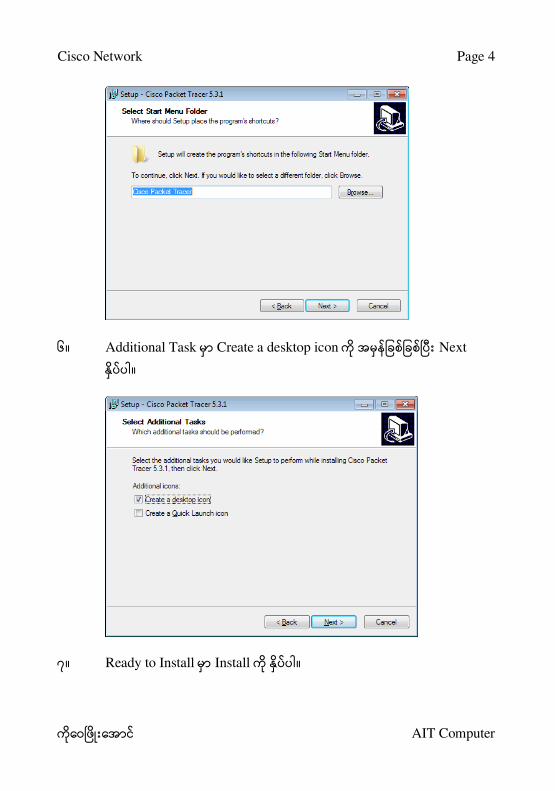
၅။ Start Menu Next ။
Cisco Network Page 4
AIT Computer
၆။ Additional Task Create a desktop icon Next
။
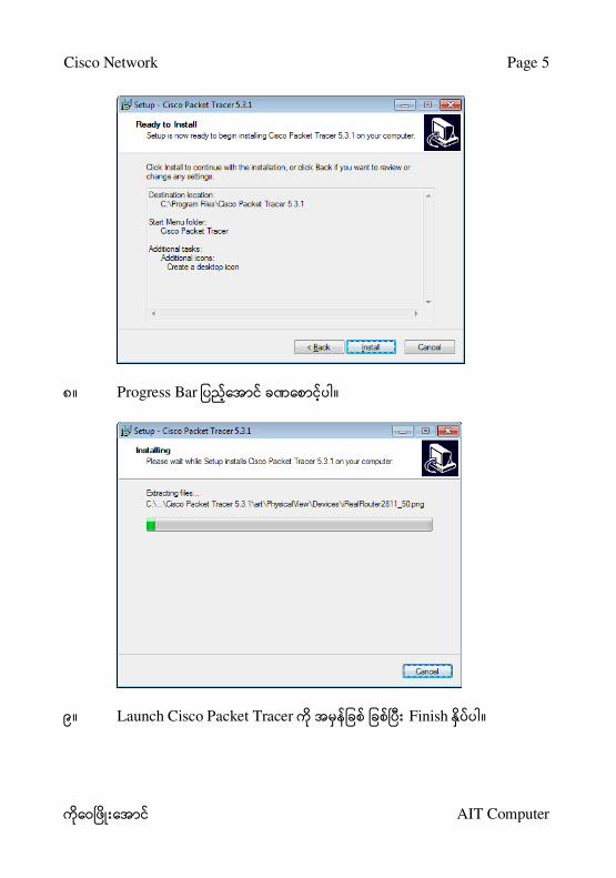
၇။ Ready to Install Install ။
Cisco Network Page 5
AIT Computer
၈။ Progress Bar ။
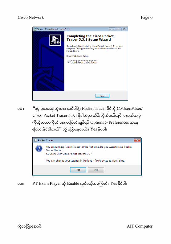
၉။ Launch Cisco Packet Tracer Finish ။
Cisco Network Page 6
AIT Computer
၁၀ ။ “ ၊ Packet Tracer C:/Users/User/
Cisco Packet Tracer 5.3.1 ၊
Options > Preferences
” ။ Yes ။
၁၁။ PT Exam Player Enable Yes ။

Cisco Network Page 7
AIT Computer
၁၂။ PT Updater Enable Yes ။

Cisco Network Page 8
AIT Computer
Chapter 2
User Interface
Packet Tracer User Interface
။ Window Application Title Bar,
Menu Bar, Tool Bar, Application Window, Status Bar
။
၁။ Desktop Cisco Packet Tracer icon Double Click ။
၂။ Splash Screen ။

Cisco Network Page 9
AIT Computer
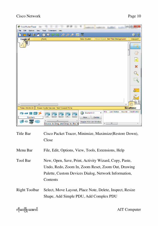
၃။ Software User Interface ။
Cisco Network Page 10
AIT Computer
Title Bar Cisco Packet Tracer, Minimize, Maximize(Restore Down),
Close
Menu Bar File, Edit, Options, View, Tools, Extensions, Help
Tool Bar New, Open, Save, Print, Activity Wizard, Copy, Paste,
Undo, Redo, Zoom In, Zoom Reset, Zoom Out, Drawing
Palette, Custom Devices Dialog, Network Information,
Contents
Right Toolbar Select, Move Layout, Place Note, Delete, Inspect, Resize
Shape, Add Simple PDU, Add Complex PDU
Cisco Network Page 11
AIT Computer
Bottom Toolbar Device, Connection, Animation

Cisco Network Page 12
AIT Computer
Chapter 3
Starting Cisco Packet Tracer
Packte Tracer
။ LAB
Networking Packet
Tracer ။
Step By Step CCNA Exam Ready
။
LAB (၉) ။
Step 1: Start Packet Tracer
Step 2: Choosing Devices and Connections
Step 3: Building the Topology „ Adding Hosts
Step 4: Building the Topology „ Connecting the Hosts to Hubs and Switches
Step 5: Configuring IP Addresses and Subnet Masks on the Hosts
Step 6: Connecting Hub0 to Switch0
Step 7: Verifying Connectivity in Realtime Mode
Step 8: Verifying Connectivity in Simulation Mode
Step 9: Saving the Topology

Cisco Network Page 13
AIT Computer
Step 1: Start Packet Tracer
(၁) Start ။ Packet
Tracer Software ။
Step 2: Choosing Devices and Connections
Network Device Cable
။ Network Topology ။
LAB End Devices, Switches, Hubs Connections ။
။ Group ။
။ Device
။
Step 3: Building the Topology „ Adding Hosts
၁။ End Devices ။
၂။ Generic host ။

Cisco Network Page 14
AIT Computer
၃။ Topology Area Mouse Pointer “+”
။
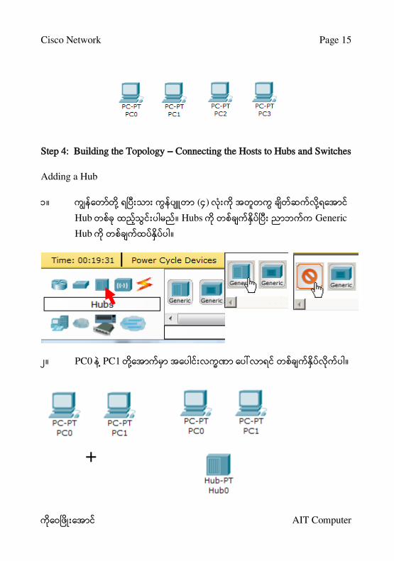
၄။ PC-PT PC0 icon ။
၅။ ။
Cisco Network Page 15
AIT Computer
Step 4: Building the Topology „ Connecting the Hosts to Hubs and Switches
Adding a Hub
၁။ (၄)
Hub ။ Hubs Generic
Hub ။
၂။ PC0 PC1 ။

Cisco Network Page 16
AIT Computer
၃။ PC0 Hub0 Connection ။
Connections ။
၄။ Copper Straight-through ။
၅။ PC0 Hub0 ။
၁။ PC0 ။
၂။ FastEthernet ။
၃။ Cursor Hub0 ။
၄။ Hub0 Port0 ။
၅။ (၂) ။ Active
။

Cisco Network Page 17
AIT Computer
1 2 3 4 5
၆။ Hub0 Port 1 PC1
။
Adding a Switch
၇။ Switch 2950-24 Switch ။

Cisco Network Page 18
AIT Computer
၈။ PC2 PC3 ။
၉။ PC2 Switch0 Connection ။ Connections ။
၁၀ ။ Copper Straight-through ။

Cisco Network Page 19
AIT Computer
၁၁။ PC2 Switch0 Step By Step
။
၁။ PC2 ။
၂။ FastEthernet ။
၃။ Cursor Switch0 ။
၄။ Switch0 FastEthernet0/1 ။
၅။ PC2 Ethernet NIC
။ light Switch0 FastEthernet0/1 port
။ switch port frames
။ Spanning Tree Protocol (STP)
။ STP Process
။ Ready ။
၆။ 30 ။
Forwarding Stage ။
Frames switch port Forward ။

Cisco Network Page 20
AIT Computer
1 2 3 4 5 6
၁၂။ Switch0 Port 3 FastEthernet0/2 PC3
။
၁၃။ Port Number Link Light
။ Fa0/1 ။ Fa FastEthernet
100 Mpbs Ethernet
။

Cisco Network Page 21
AIT Computer
Step 5: Configuring IP Addresses and Subnet Masks on the Hosts
Host IP Address Subnet Mask ။
99-002 Network ။
၁။ PC0 ။ Property Dialog Box
။

Cisco Network Page 22
AIT Computer
၂။ Config Tab Setting ။ Display Name PC0
။ Static Gateway 172.16.1.1 ,
DNS Server 172.16.1.100 ။
။
၃။ Interface FastEthernet ။ IP Configuration
Static IP Address 172.16.1.10 Subnet Mask
255.255.0.0 ။ Subnet Mask
။ IP Address Tab Key Auto
။

Cisco Network Page 23
AIT Computer
၄။ dialog box “X” ။
၅။ Host IP
။ Information ။
Cisco Network Page 24
AIT Computer
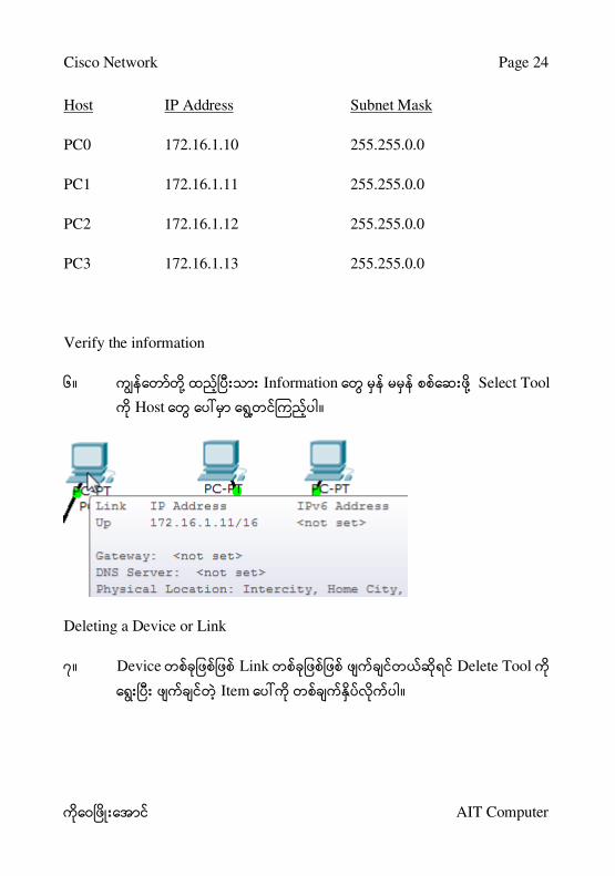
Host IP Address Subnet Mask
PC0 172.16.1.10 255.255.0.0
PC1 172.16.1.11 255.255.0.0
PC2 172.16.1.12 255.255.0.0
PC3 172.16.1.13 255.255.0.0
Verify the information
၆။ Information Select Tool
Host ။
Deleting a Device or Link
၇။ Device Link Delete Tool
Item ။

Cisco Network Page 25
AIT Computer
Step 6: Connecting Hub0 to Switch0
Hub Switch Cross-over Cable
။ Connection Option Copper Cross-Over ။
၂။ Connection Cursor Hub0 ။
၃။ Port 5 ။

Cisco Network Page 26
AIT Computer
၄။ Connection Cursor Switch0 ။
၅။ Switch0 FastEthernet0/4 ။
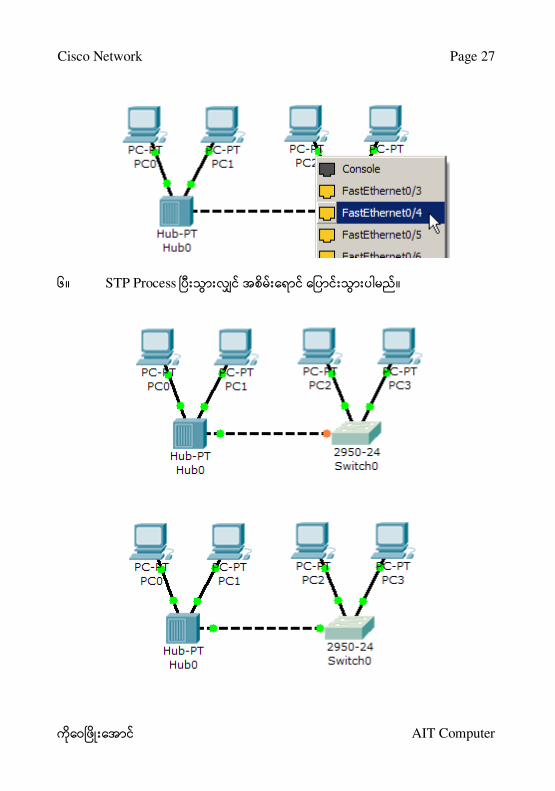
Cisco Network Page 27
AIT Computer
၆။ STP Process ။
Cisco Network Page 28
AIT Computer
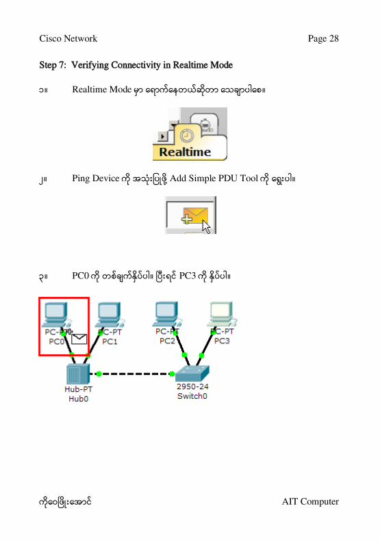
Step 7: Verifying Connectivity in Realtime Mode
၁။ Realtime Mode ။
၂။ Ping Device Add Simple PDU Tool ။
၃။ PC0 ။ PC3 ။

Cisco Network Page 29
AIT Computer
၄။ PDU Last Status Successful ။
၅။ PC3 IP Address 172.16.2.13 ။ PC0
PC3 Ping Result ။
_______________________________________________________
၆။ PC2 IP Address 172.16.2.12 ။ PC0
PC2 Ping Result ။
_______________________________________________________
Cisco Network Page 30
AIT Computer
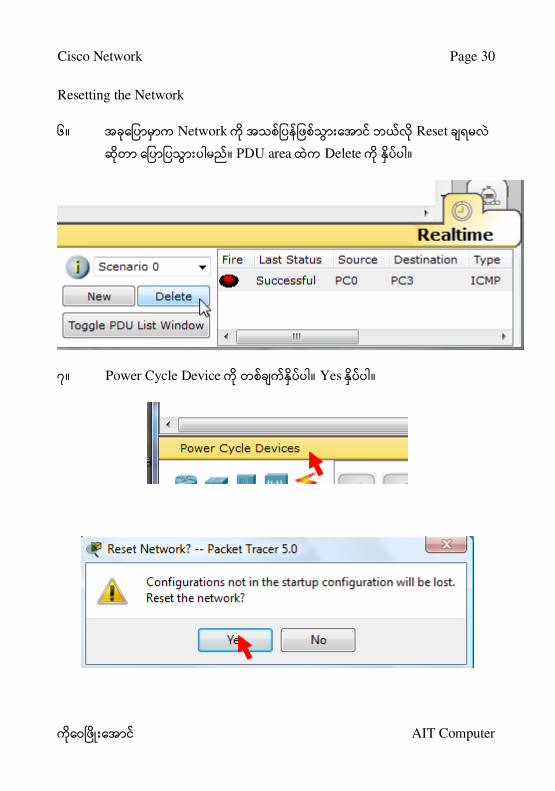
Resetting the Network
၆။ Network Reset
။ PDU area Delete ။
၇။ Power Cycle Device ။ Yes ။

Cisco Network Page 31
AIT Computer
Waiting for Spanning Tree Protocol (STP)
Switch Device Spanning Tree Protocol
။ Ready ။
Ethernet Frame Forward ။
။ ။
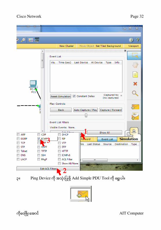
Step 8: Verifying Connectivity in Simulation Mode
၁။ Simulation mode ။
၂။ Edit Filter ။ Filter Deselect
Show All/None ။ ICMP
။
Cisco Network Page 32
AIT Computer
၃။ Ping Device Add Simple PDU Tool ။
1
2
3

Cisco Network Page 33
AIT Computer
၄။ PC0 ၊ PC3 ။
၅။ ICMP ping Capture/Foreard button ။
ICMP Message Host, Hub, Switch
။ PDU Last Status
Successful ။ Buffer Full Clear Event List
။

Cisco Network Page 34
AIT Computer
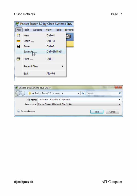
Step 9: Saving the Topology
၁။ Topology ။ .pkt
Extension ။
၂။ File > Save As ။ Save ။
Cisco Network Page 35
AIT Computer

Cisco Network Page 36
AIT Computer
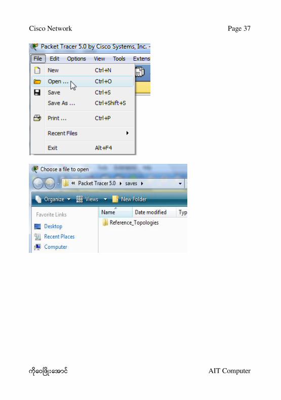
Opening Existing Topologies
၃။ File > Open ။
၄။ Open ။
Opening Existing PT Topologies
၅။ Template Open ။
Cisco Network Page 37
AIT Computer

Cisco Network Page 38
AIT Computer
Lecturer's Signature :
Instructor's Signature :
Date :
Time :

Cisco Network Page 39
AIT Computer
Chapter 4
Preparing Network
Cisco Network Packet Tracer Software
။
။
။
၁။ Device Area End Devices ။ Shortcut Ctrl + Alt + V
။
၂။ Detail Device Area End Device ။
၃။ Generic PC-PT ။ ။
Cisco Network Page 40
AIT Computer
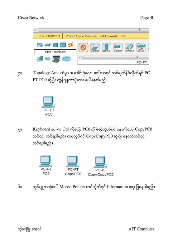
၄။ Topology Area PC-
PT PC0 ။
၅။ Keyboard Ctrl PC0 CopyPC0
။ CopyCopyPC0
။
၆။ Mouse Pointer Information ။

Cisco Network Page 41
AIT Computer
၇။ PC0 Double Click Aung Aung ၊ Enter
။ Mg Mg, Tun Tun
။
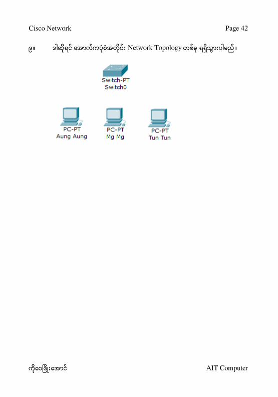
၈။ Switches Generic Switch-PT ။
Cisco Network Page 42
AIT Computer
၉။ Network Topology ။

Cisco Network Page 43
AIT Computer
Chapter 5
IP Address on Cisco Packet Tracer
IP Address ။
။
။
၁။ Aung Aung Double Click ။
၂။ Config Tab ။ Fast Ethernet ။

Cisco Network Page 44
AIT Computer
၃။ IP Configuration Static IP Address: 192.168.1.1, Subnet
Mask: 255.255.255.0 ။

Cisco Network Page 45
AIT Computer
Aung Aung
192.168.1.1
255.255.255.0
Mg Mg
192.168.1.2

Cisco Network Page 46
AIT Computer
Tun Tun
192.168.1.3
IP Address
၁။ Desktop IP Configuration ။
၂။ ။

Cisco Network Page 47
AIT Computer

Cisco Network Page 48
AIT Computer
Chapter 6
Connecting Cable
Packet Tracer Cable ။
Cable Type Description
Console
Console connections can be made between PCs and routers
or switches. Certain conditions must be met for the console
session from the PC to work: the speed on both sides of the
connection must be the same, the data bits must be 7 for
both or 8 for both, the parity must be the same, the stop bits
must be 1 or 2 (but they do not have to be the same), and the
flow control can be anything for either side.
Copper
Straight-
through
This cable type is the standard Ethernet media for
connecting between devices that operate at different OSI
layers (such as hub to router, switch to PC, and router to
hub). It can be connected to the following port types: 10
Mbps Copper (Ethernet), 100 Mbps Copper (Fast Ethernet),
and 1000 Mbps Copper (Gigabit Ethernet).
Copper Cross-
over
This cable type is the Ethernet media for connecting
between devices that operate at the same OSI layer (such as
hub to hub, PC to PC, PC to printer). It can be connected to
the following port types: 10 Mbps Copper (Ethernet), 100
Mbps Copper (Fast Ethernet), and 1000 Mbps Copper
(Gigabit Ethernet).
Fiber
Fiber media is used to make connections between fiber ports
(100 Mbps or 1000 Mbps).

Cisco Network Page 49
AIT Computer
Phone
Phone line connections can only be made between devices
with modem ports. The standard application for modem
connections is an end device (such as a PC) dialing into a
network cloud.
Coaxial
Coaxial media is used to make connections between coaxial
ports such as a cable modem connected to a Packet Tracer
Cloud.
Serial DCE and
DTE
Serial connections, often used for WAN links, must be
connected between serial ports. Note that you must enable
clocking on the DCE side to bring up the line protocol. The
DTE clocking is optional. You can tell which end of the
c onne c tion is the DC E side by the sma ll “c loc k” ic on ne xt
to the port. If you choose the Serial DCE connection type
and then connect two devices, the first device will be the
DCE side and the second device will be automatically set to
the DTE side. The reverse is true if you choose the Serial
DTE connection type.
Cable ။
Straight-through Cross-over ။
၊ Switch Cross-over
Straight-through ။
၁။ Connections Area ။

Cisco Network Page 50
AIT Computer
၂။ Copper Straight-Through ။
၃။ FastEthernet ။

Cisco Network Page 51
AIT Computer
၄။ Switch FastEthernet0/1 ။
၅။ ။

Cisco Network Page 52
AIT Computer
၆။ Mouse Pointer Information
။
Cisco Network Page 53
AIT Computer
Chapter 7
Testing Connection using Ping Command
Network ။
။ ping command ။
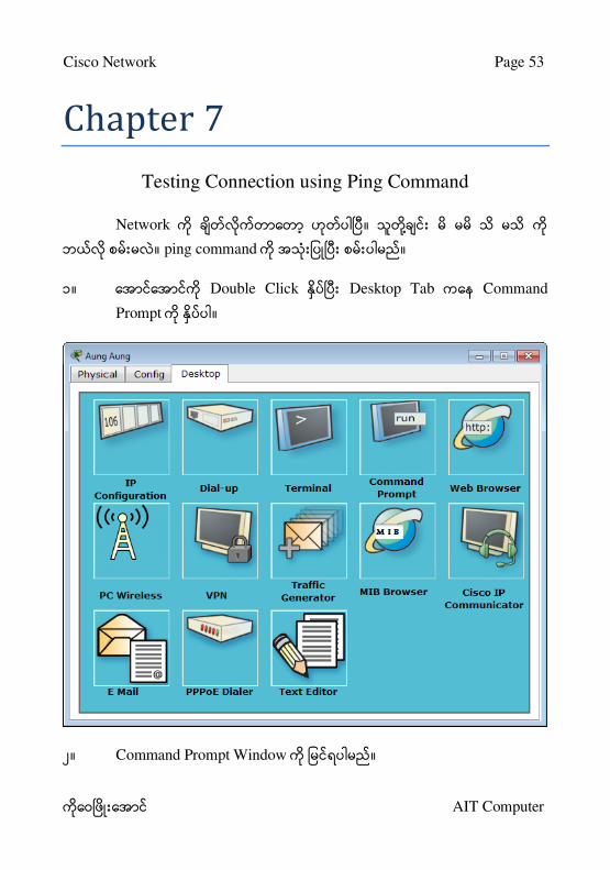
၁။ Double Click Desktop Tab Command
Prompt ။
၂။ Command Prompt Window ။

Cisco Network Page 54
AIT Computer
၃။ ping 192.168.1.3 Enter ။
၄။ Reply from 192.168.1.3 ။
Packet Tracer PC Command Line 1.0
PC>ping 192.168.1.3

Cisco Network Page 55
AIT Computer
Pinging 192.168.1.3 with 32 bytes of data:
Reply from 192.168.1.3: bytes=32 time=17ms TTL=128
Reply from 192.168.1.3: bytes=32 time=8ms TTL=128
Reply from 192.168.1.3: bytes=32 time=8ms TTL=128
Reply from 192.168.1.3: bytes=32 time=7ms TTL=128
Ping statistics for 192.168.1.3:
Packets: Sent = 4, Received = 4, Lost = 0 (0% loss),
Approximate round trip times in milli-seconds:
Minimum = 7ms, Maximum = 17ms, Average = 10ms
PC>

Cisco Network Page 56
AIT Computer
Chapter 8
Connect Switch to Switch
Connection ။ Switch Cross
Over ။ ။
IP ။
Mya Mya
192.168.1.11
Thu Thu
192.168.1.12

Cisco Network Page 57
AIT Computer
Soe Soe
192.168.1.13
Ping ။
PC>ping 192.168.1.13
Pinging 192.168.1.13 with 32 bytes of data:
Reply from 192.168.1.13: bytes=32 time=20ms TTL=128
Reply from 192.168.1.13: bytes=32 time=13ms TTL=128
Reply from 192.168.1.13: bytes=32 time=12ms TTL=128
Reply from 192.168.1.13: bytes=32 time=11ms TTL=128
Ping statistics for 192.168.1.13:
Packets: Sent = 4, Received = 4, Lost = 0 (0% loss),
Approximate round trip times in milli-seconds:
Minimum = 11ms, Maximum = 20ms, Average = 14ms
PC>

Cisco Network Page 58
AIT Computer
Chapter 9
Copying Diagram
၁။ Network
။ Select ။
၂။ ။
၃။ Su Su, Hla Hla, Ma Ma ။

Cisco Network Page 59
AIT Computer
၄။ Switch Marketing, Sales ။
၅။ IP ။
Su Su
192.168.2.1
Hla Hla
192.168.2.2
Ma Ma
192.168.2.3

Cisco Network Page 60
AIT Computer

Cisco Network Page 61
AIT Computer
Chapter 10
Saving Lesson File
၁။ File > Save ။
၂။ New Folder ။

Cisco Network Page 62
AIT Computer
၃။ AIT Cisco ။
၄။ File Name Lesson 1 Save ။

Cisco Network Page 63
AIT Computer

Cisco Network Page 64
AIT Computer
Chapter 11
Connect Different Network Using Router
Network Router
။ Network A 192.168.1.0 Network B
192.168.2.0 ။
Ping ။
1 Network 2 Network ping Request timed out
။

Cisco Network Page 65
AIT Computer
Packet Tracer PC Command Line 1.0
PC>ping 192.168.2.1
Pinging 192.168.2.1 with 32 bytes of data:
Request timed out.
Request timed out.
Request timed out.
Request timed out.
Ping statistics for 192.168.2.1:
Packets: Sent = 4, Received = 0, Lost = 4 (100% loss),
PC>
Note ။
၁။ Place Note ။

Cisco Network Page 66
AIT Computer
၂။ ။

Cisco Network Page 67
AIT Computer
၃။ AIT Computer Network ။
Adding Router
၁။ Router Router ။
၂။ 2811 Router ။

Cisco Network Page 68
AIT Computer
၃။ ။
၄။ Link Down ။
၅။ Router Double Click ။

Cisco Network Page 69
AIT Computer
၆။ Config Tab ။

Cisco Network Page 70
AIT Computer
၇။ FastEthernet0/0 IP Address: 192.168.1.10, Subnet
Mask: 255.255.255.0 ။

Cisco Network Page 71
AIT Computer
၈။ Port Status On ။

Cisco Network Page 72
AIT Computer
၉။ Switch Router ။

Cisco Network Page 73
AIT Computer
၁၀ ။ FastEthernet0/1 Port Status On, IP Address:
192.168.2.10, Subnet Mask: 255.255.255.0 ။

Cisco Network Page 74
AIT Computer
၁၁။ Link Up ။
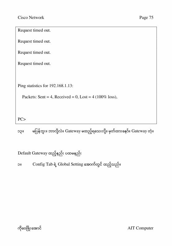
၁၂။ Ping ။ Reply ။
PC>ping 192.168.1.13
Pinging 192.168.1.13 with 32 bytes of data:
Cisco Network Page 75
AIT Computer
Request timed out.
Request timed out.
Request timed out.
Request timed out.
Ping statistics for 192.168.1.13:
Packets: Sent = 4, Received = 0, Lost = 4 (100% loss),
PC>
၁၃။ ။ ။ Gateway ။ ။ Gateway ။
Default Gateway
၁။ Config Tab Global Setting ။

Cisco Network Page 76
AIT Computer
Default Gateway
၁။ Desktop Tab IP Configuration ။

Cisco Network Page 77
AIT Computer
၂။ Default Gateway 192.168.1.10 ။

Cisco Network Page 78
AIT Computer
၃။ Network B Gateway ။
၄။ Network B Gateway 192.168.2.10 ။

Cisco Network Page 79
AIT Computer
၄။ Gateway 192.168.2.10 ။

Cisco Network Page 80
AIT Computer
Chapter 12
Connecting A,B and C Network
LAB Network ။ Network C
။ IP 192.168.3.0 ။
IP Address ။
Manager
IP Address 192.168.3.1
Default Gateway: 192.168.3.10
Accountant
IP Address 192.168.3.2
Default Gateway: 192.168.3.10

Cisco Network Page 81
AIT Computer
Secretary
IP Address 192.168.3.3
Default Gateway: 192.168.3.10
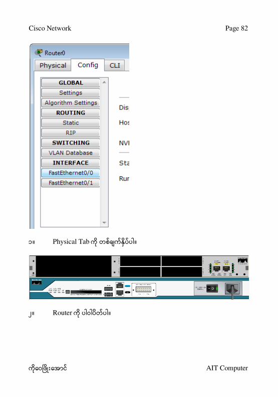
Adding Network Ports to Router
။ Router Port
။ Interface FastEthernet0/0 FastEthernet0/1
။ ။ Port
။
Cisco Network Page 82
AIT Computer
၁။ Physical Tab ။
၂။ Router ။

Cisco Network Page 83
AIT Computer
၃။ NM-2FE2W ။

Cisco Network Page 84
AIT Computer
၄။ ။
၅။ Router ။
၆။ Power ။
၇။ Config Tab Device is still booting
။ ။

Cisco Network Page 85
AIT Computer
၈။ FastEthernet ။

Cisco Network Page 86
AIT Computer
၉။ FastEthernet1/0 Port Status On, IP Address: 192.168.3.10,
Subnet Mask: 255.255.255.0 ။

Cisco Network Page 87
AIT Computer
၁၀ ။ Port Network C ။

Cisco Network Page 88
AIT Computer
၁၁။ Network Ping Ping
Reply ။
Packet Tracer PC Command Line 1.0
PC>ping 192.168.2.3
Pinging 192.168.2.3 with 32 bytes of data:
Reply from 192.168.2.3: bytes=32 time=15ms TTL=127
Reply from 192.168.2.3: bytes=32 time=15ms TTL=127

Cisco Network Page 89
AIT Computer
Reply from 192.168.2.3: bytes=32 time=16ms TTL=127
Reply from 192.168.2.3: bytes=32 time=16ms TTL=127
Ping statistics for 192.168.2.3:
Packets: Sent = 4, Received = 4, Lost = 0 (0% loss),
Approximate round trip times in milli-seconds:
Minimum = 15ms, Maximum = 16ms, Average = 15ms
PC>
Cisco Network Page 90
AIT Computer
Chapter 13
Working with the Application Layer: DHCP, DNS, HTTP,
HTTPS, Email
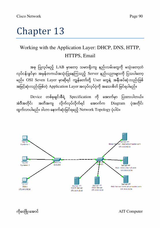
LAB
Server
။ OSI Seven Layer User :
Application Layer ။
Device Specification ။
Diagram
။ Network Topology ။

Cisco Network Page 91
AIT Computer
Instructions:
၁။ Realtime mode Packet Tracer ။
Options -> Preferences
o Ena ble “S how Link Lights”
o Disa ble “Hide De vic e La be l”
၂။ Configuring the DHCP Server
Add a server.
Global Settings:
Display Name “DHCP Server” ။
Gateway 172.16.0.1 ။
FastEthernet:
IP address 172.16.0.10
Subnet Mask 255.255.0.0
HTTP:
HTTP Service HTTPS Service Off
DHCP:

Cisco Network Page 92
AIT Computer
Default Gateway 172.16.0.1
DNS Server 172.16.0.11
Start IP Address 172.16.0.100
DNS:
DNS Service Off
Email:
SMTP Service POP3 Service Off
၃။ Configuring the DNS Server
Add a server.
Global Settings:
Display Name “DNS Server” ။
Gateway 172.16.0.1 ။
FastEthernet:
IP address 72.16.0.11
Subnet Mask 255.255.0.0
HTTP:

Cisco Network Page 93
AIT Computer
HTTP Service HTTPS Service Off
DHCP:
DHCP Service Off
DNS:
www.aitcomputer.com Domain Name
Domain Name www.aitcomputer.com
IP Address 172.16.0.20
Add
Entering the www.internal.com Domain Name
Domain Name www.internal.com
IP Address 172.16.0.30
Add
Email:
SMTP Service POP3 Service Off
၂။ Configuring the www.aitcomputer.com Web Server
Add a server.
Global Settings:
Display Name “Web Server: www.aitcomputer.com”
Gateway 172.16.0.1 ။
FastEthernet:

Cisco Network Page 94
AIT Computer
IP address 172.16.0.20
Subnet Mask 255.255.0.0
DHCP:
DHCP Service Off
DNS:
DNS Service Off
HTTP
HTTP HTTPS Service On
။ “<hr >
Welcome to Cisco Packet Tracer. Opening doors to new
oppor tunitie s. M ind Wide Ope n.” to “<hr > We lc ome to AI T
Computer’s of Tec hnology’s public we b pa ge ! ” You may
add other information as well.
Email:
SMTP Service POP3 Service Off
၄။ Configuring the www.internal.com Web Server
Add a server.
Global Settings:
Display Name “Web Server: www.internal.com”
Gateway 172.16.0.1
FastEthernet:
IP address 172.16.0.30
Cisco Network Page 95
AIT Computer
Subnet Mask 255.255.0.0
DHCP:
DHCP Service Off
DNS:
DNS Service Off
HTTP:
။ “<hr > We lc ome to C isc o Pa c ke t Tr ace r .
Ope ning door s to ne w oppor tunitie s. M ind Wide Ope n.” to
“<hr > This is the c or pora te inte r na l ne twor k! ” You ma y a dd
other information as well.
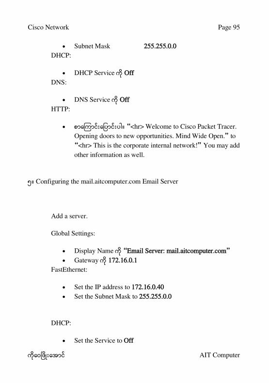
၅။ Configuring the mail.aitcomputer.com Email Server
Add a server.
Global Settings:
Display Name “Email Server: mail.aitcomputer.com”
Gateway 172.16.0.1
FastEthernet:
Set the IP address to 172.16.0.40
Set the Subnet Mask to 255.255.0.0
DHCP:
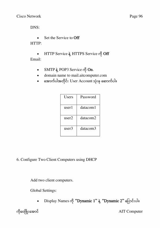
Set the Service to Off
Cisco Network Page 96
AIT Computer
DNS:
Set the Service to Off
HTTP:
HTTP Service HTTPS Service Off
Email:
SMTP POP3 Service On.
domain name to mail.aitcomputer.com
User Account ။
Users Password
user1 datacom1
user2 datacom2
user3 datacom3
6. Configure Two Client Computers using DHCP
Add two client computers.
Global Settings:
Display Names “Dynamic 1” “Dynamic 2” ။

Cisco Network Page 97
AIT Computer
Gateway/DNS DHCP ။
FastEthernet:
IP Configuration DHCP ။
6. Configure One Client Computers using Static IP Addressing
Add two client computers.
Global Settings:
Display Name “Static”
Gateway/DNS Static
Gateway 172.16.0.1
DNS Server 172.16.0.11
FastEthernet:
Static ။
IP address 172.16.0.90
Subnet Mask 255.255.0.0
၇။ Configure Email Configuration for Clients

Cisco Network Page 98
AIT Computer

Cisco Network Page 99
AIT Computer

Cisco Network Page 100
AIT Computer
၈။ Adding switches
Switch ။
servers switch straight-through cable ။
client computers switch straight-through cable
။
switch crossover cable ။

Cisco Network Page 101
AIT Computer
၉။ Verify connectivity
Ping (ICMP)
o client computer Desktop Command prompt
client computer server Ping ။
o Example: Dynamic 1 client C> ping 172.16.0.20
Enter
o Ping Fail ။
Reply ။
ARP Process Ping Timing
Out ။
Web Browser (HTTP)
o client computer Desktop Web Browser Web
Servers URL www.aitcomputer.com
www.internal.com ။
o servers web page ။
Email (SMTP)
o client computer (Dynamic 1) Email ။
client computer (Static)
o Static PC email icon (Desktop tab) Receive button
Mail ။
I nstr uc tor ’s S igna ture :
__________________________________________
Cisco Network Page 102
AIT Computer
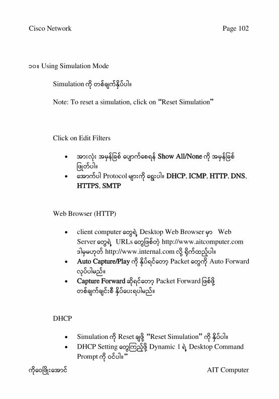
၁၀ ။ Using Simulation Mode
Simulation ။
Note : To re se t a sim ula tion, c lic k on “R e se t S im ula tion”
Click on Edit Filters
Show All/None
။
Protocol ။ DHCP, ICMP, HTTP, DNS,
HTTPS, SMTP
Web Browser (HTTP)
client computer Desktop Web Browser Web
Server URLs http://www.aitcomputer.com
http://www.internal.com ။
Auto Capture/Play Packet Auto Forward
။
Capture Forward Packet Forward
။
DHCP
Simulation Reset “Re se t S im ula tion” ။
DHCP Setting Dynamic 1 Desktop Command
Prompt ။ “

Cisco Network Page 103
AIT Computer
DHCP IP Address ipconfig /all
Enter ။
IP Address C> ipconfig /renew
။
“R e se t S im ula tion” ။
Email Animation Source Client
Computer ၊ Destination Client
Computer
Auto Capture/Play Capture Forward
။
Cisco Network Page 104
AIT Computer
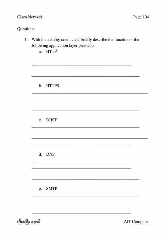
Questions:
1. With the activity conducted, briefly describe the function of the
following application layer protocols:
a. HTTP
_______________________________________________________
_______________________________________________
___________________________________________________
b. HTTPS
_______________________________________________________
_______________________________________________
___________________________________________________
c. DHCP
___________________________________________________
_______________________________________________________
_______________________________________________
d. DNS
_______________________________________________________
_______________________________________________
___________________________________________________
e. SMTP
___________________________________________________
_______________________________________________________
_______________________________________________
Cisco Network Page 105
AIT Computer
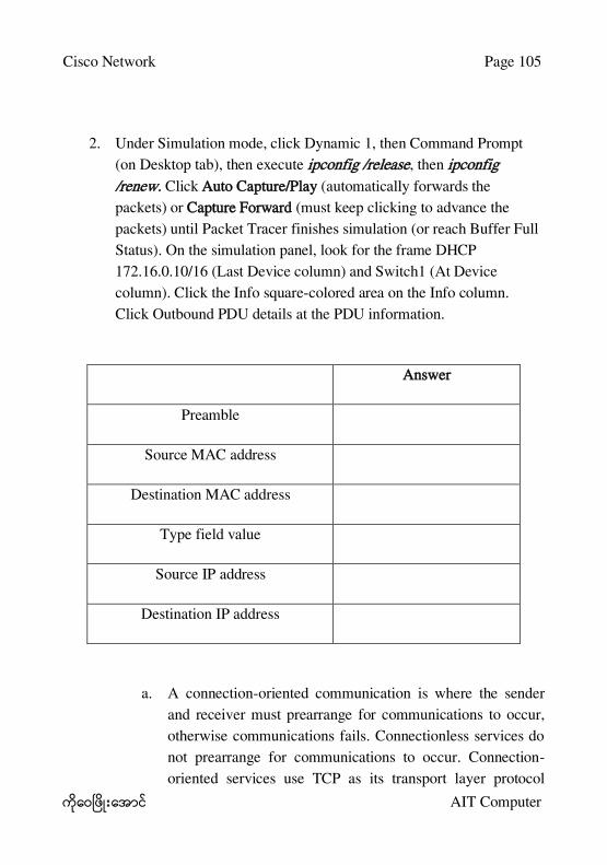
2. Under Simulation mode, click Dynamic 1, then Command Prompt
(on Desktop tab), then execute ipconfig /release, then ipconfig
/renew. Click Auto Capture/Play (automatically forwards the
packets) or Capture Forward (must keep clicking to advance the
packets) until Packet Tracer finishes simulation (or reach Buffer Full
Status). On the simulation panel, look for the frame DHCP
172.16.0.10/16 (Last Device column) and Switch1 (At Device
column). Click the Info square-colored area on the Info column.
Click Outbound PDU details at the PDU information.
Answer
Preamble
Source MAC address
Destination MAC address
Type field value
Source IP address
Destination IP address
a. A connection-oriented communication is where the sender
and receiver must prearrange for communications to occur,
otherwise communications fails. Connectionless services do
not prearrange for communications to occur. Connection-
oriented services use TCP as its transport layer protocol

Cisco Network Page 106
AIT Computer
whereas connectionless services use UDP. Is DHCP a
connection-oriented service or a connectionless service? Is
DHCP running TCP or UDP services? What is the source
port used by DHCP servers?
_________________________________________________
_____________________________________________
_________________________________________________
_____________________________________________
b. From the five application protocols under study, identify the
three protocols using TCP services.
_________________________________________________
_____________________________________________
3. Under Simulation mode, click Dynamic 2, then Command Prompt
(on Desktop tab), then type the URL http://www.internal.com on the
web browser. Similarly, do the same for Static PC, typing in
https://www.internal.com. Click Auto Capture/Play (automatically
forwards the packets) or Capture Forward (must keep clicking to
advance the packets) until Packet Tracer finishes simulation (or reach
Buffer Full Status).
a. Before the interaction of the clients using HTTP and HTTPS,
what protocol was used first?
_________________________________________________
_____________________________________________
b. What is the source port used by HTTP servers? HTTPS
servers?
Cisco Network Page 107
AIT Computer
_________________________________________________
_____________________________________________
c. Look at any PDU information containing an HTTP frame
and another PDU information containing HTTPS frame.
Look at the difference between the data stored via HTTP
with that of HTTPS.
_________________________________________________
_____________________________________________
_________________________________________________
_____________________________________________
4. Under Simulation mode, click Dynamic 1, then send email on one of
the other client computers. Click Auto Capture/Play (automatically
forwards the packets) or Capture Forward (must keep clicking to
advance the packets) until Packet Tracer finishes simulation (or reach
Buffer Full Status).
a. Before the interaction of the clients using SMTP, what
protocol was used first?
_________________________________________________
_____________________________________________
b. What is the source port used by servers running SMTP?
_________________________________________________
_____________________________________________
5. By identifying the protocols serviced by TCP and UDP, identify
three fields present in TCP that are not found in UDP.

Cisco Network Page 108
AIT Computer
_______________________________________________________
_______________________________________________________
___________________________________________
6. Perform a ping from Dynamic 1 to Dynamic 2 under Simulation
mode.
Note: Before doing a ping, type in arp „d at the command prompt of
Dynamic 1 and execute arp „a after. Internet address and Physical
address must be empty after typing arp -a
a. Before the interaction of the clients with ping, what protocol
was used first?
_______________________________________________
b. Execute arp „a after the successful ping. Write down the
internet address and physical address on Dynamic 1.
_________________________________________________
_____________________________________________
c. Analyze the first ICMP frame and complete the table below.
Answer
Source IP Address
Destination IP Address
ICMP Type value
ICMP Code value
Source Ethernet Address
Destination Ethernet Address
Internet Protocol version
Time to Live (TTL) value

Cisco Network Page 109
AIT Computer
Chapter 14
Connect A, B Network using Two Routers
Network A
Host A Router A
IP 192.168.0.2 Fa0/0 192.168.10.1/24
SM 255.255.255.0 Fa0/1 192.168.0.1/24
DG 192.168.0.1
Network B
Host B Router B
IP 192.168.20.2 Fa0/1 192.168.20.1
SM 255.255.255.0 Fa0/0 192.168.10.2

Cisco Network Page 110
AIT Computer
DG 192.168.20.1
Port Label ။
၁။ Options Menu Preferences ။
၂။ Always Show Port Label ။

Cisco Network Page 111
AIT Computer
R oute r A’s R outing Ta ble
၁။ Router A Double Click ။
၂။ Config Tab ။
၃။ Routing Static ။
၄။ Network 192.168.20.0 ။
၅။ Mask 255.255.255.0 ။
၆။ Next Hop 192.168.10.2 ။

Cisco Network Page 112
AIT Computer
IP Route [Destination] [Mask] [Gateway]
192.168.20.0 255.255.255.0 192.168.10.2
Router#show ip route
Codes: C - connected, S - static, I - IGRP, R - RIP, M - mobile, B - BGP
D - EIGRP, EX - EIGRP external, O - OSPF, IA - OSPF inter area
N1 - OSPF NSSA external type 1, N2 - OSPF NSSA external type 2
E1 - OSPF external type 1, E2 - OSPF external type 2, E - EGP
i - IS-IS, L1 - IS-IS level-1, L2 - IS-IS level-2, ia - IS-IS inter area
* - candidate default, U - per-user static route, o - ODR
P - periodic downloaded static route
Gateway of last resort is not set
C 192.168.0.0/24 is directly connected, FastEthernet0/1
C 192.168.10.0/24 is directly connected, FastEthernet0/0
S 192.168.20.0/24 [1/0] via 192.168.10.2
Router#

Cisco Network Page 113
AIT Computer
R oute r’B R outing Ta ble
၁။ Router B Double Click ။
၂။ Config Tab ။
၃။ Routing Static ။
၄။ Network 192.168.0.0 ။
၅။ Mask 255.255.255.0 ။
၆။ Next Hop 192.168.10.1 ။

Cisco Network Page 114
AIT Computer
IP Route [Destination] [Mask] [Gateway]
192.168.0.0 255.255.255.0 192.168.10.1
Router#show ip route
Codes: C - connected, S - static, I - IGRP, R - RIP, M - mobile, B - BGP
D - EIGRP, EX - EIGRP external, O - OSPF, IA - OSPF inter area
N1 - OSPF NSSA external type 1, N2 - OSPF NSSA external type 2
E1 - OSPF external type 1, E2 - OSPF external type 2, E - EGP
i - IS-IS, L1 - IS-IS level-1, L2 - IS-IS level-2, ia - IS-IS inter area
* - candidate default, U - per-user static route, o - ODR
P - periodic downloaded static route
Gateway of last resort is not set
S 192.168.0.0/24 [1/0] via 192.168.10.1
C 192.168.10.0/24 is directly connected, FastEthernet0/0
C 192.168.20.0/24 is directly connected, FastEthernet0/1
Router#
Cisco Network Page 115
AIT Computer
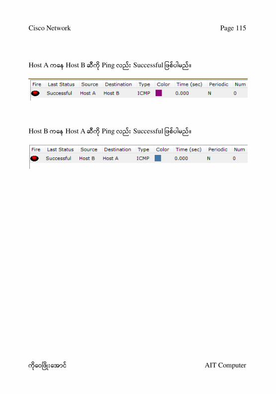
Host A Host B Ping Successful ။
Host B Host A Ping Successful ။

Cisco Network Page 116
AIT Computer
Chapter 15
Connect A, B Network using Three Routers
IP Specification
Host A Host C
IP: 192.168.0.2
Mask: 255.255.255.0
Default Gateway: 192.168.0.1
IP: 192.168.30.2
Mask: 255.255.255.0
Default Gateway: 192.168.30.1
Router A Router C
Fa0/1: 192.168.0.1
Fa0/0: 192.168.10.1
Fa0/0: 192.168.30.1
Fa0/1: 192.168.20.1
Router B
Fa0/0: 192.168.10.2
Fa0/1: 192.168.20.2
Routing Table
Router Network
[Destination] Mask
Next Hop
[Gateway]
A 192.168.20.0 24 192.168.10.2

Cisco Network Page 117
AIT Computer
192.168.30.0 24 192.168.20.1
B 192.168.0.0
192.168.30.0
24
24
192.168.10.1
192.168.20.1
C 192.168.10.0
192.168.0.0
24
24
192.168.20.2
192.168.10.1
Static Route Connection ။
Host A Host C Ping Successful ။
Host C Host A Ping Successful ။

Cisco Network Page 118
AIT Computer
Chapter 16
Connect Two Routers using Serial Cable
Router Ethernet
Cable ။ Serial Cable
။
Serial Cable ။
Serial DCE (DCE Data Communication Equipment)

Cisco Network Page 119
AIT Computer
Serial DTE (DTE Data Terminal Equipment)
IP Specification
Host A Host B
IP: 192.168.0.2
Mask: 255.255.255.0
Default Gateway: 192.168.0.1
IP: 192.168.20.2
Mask: 255.255.255.0
Default Gateway: 192.168.20.1
Router A Router B
Fa0/0: 192.168.0.1
Se1/0: 192.168.10.1 (DCE)
Fa0/0: 192.168.20.1
Se1/0: 192.168.10.2 (DTE)
Routing Table
Router Network
[Destination] Mask
Next Hop
[Gateway]
A 192.168.20.0 24 192.168.10.2
B 192.168.0.0 24 192.168.10.1
Static Route Connection ။
Host A Host C Ping Successful ။
Host C Host A Ping Successful ။

Cisco Network Page 120
AIT Computer
Chapter 17
Connect Three Routers using Serial Cable
IP Specification
Host A Host B
IP: 192.168.0.2
Mask: 255.255.255.0
Default Gateway: 192.168.0.1
IP: 192.168.20.2
Mask: 255.255.255.0
Default Gateway: 192.168.20.1
Router A Router B
Fa0/0: 192.168.0.1
Se1/0: 10.10.10.1 (DTE)
Se1/1: 20.20.20.1 (DCE)
Fa0/0: 192.168.20.1
Se1/0: 10.10.10.2 (DCE)
Se1/1: 30.30.30.1 (DTE)

Cisco Network Page 121
AIT Computer
Host C
IP: 192.168.30.2
Mask: 255.255.255.0
Default Gateway: 192.168.30.1
Router C
Fa0/0: 192.168.30.1
Se1/0: 20.20.20.2 (DTE)
Se1/1: 30.30.30.2 (DCE)
Static Routing Table
Router Network
[Destination] Mask
Next Hop
[Gateway]
A 192.168.10.0
192.168.20.0
24
24
10.10.10.2
20.20.20.2
B 192.168.0.0
192.168.20.0
24
24
10.10.10.1
30.30.30.2
C 192.168.0.0
192.168.10.0
24
24
20.20.20.1
30.30.30.1
Static Route Connection ။
Host A Host B Ping Successful ။
Host A Host C Ping Successful ။
Host B Host A Ping Successful ။
Host B Host C Ping Successful ။

Cisco Network Page 122
AIT Computer
Host C Host A Ping Successful ။
Host C Host B Ping Successful ။

Cisco Network Page 123
AIT Computer
Chapter 18
RIP (Routing Information Protocol)
IP Specification
Host A Host B
IP: 192.168.0.2
Mask: 255.255.255.0
Default Gateway: 192.168.0.1
IP: 192.168.10.2
Mask: 255.255.255.0
Default Gateway: 192.168.10.1
Router A Router B
Fa0/0: 192.168.0.1
Se1/0: 172.0.0.1 (DCE)
Se1/1: 172.20.0.2 (DTE)
Fa0/0: 192.168.10.1
Se1/0: 172.10.0.1 (DCE)
Se1/1: 172.0.0.2 (DTE)

Cisco Network Page 124
AIT Computer
Host C
IP: 192.168.20.2
Mask: 255.255.255.0
Default Gateway: 192.168.20.1
Router C
Fa0/0: 192.168.20.1
Se1/0: 172.20.0.1 (DCE)
Se1/1: 172.10.0.2 (DTE)
Dynamic Routing Table
Router Network
A 192.168.0.0
172.0.0.0
172.20.0.0
B 192.168.10.0
172.0.0.0
172.10.0.0
C 192.168.20.0
172.10.0.0
172.20.0.0

Cisco Network Page 125
AIT Computer
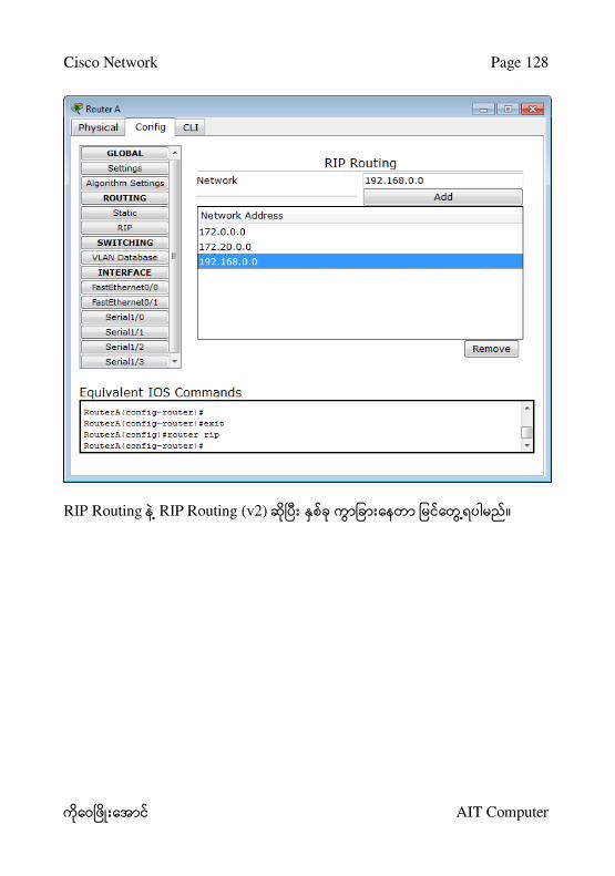
၁။ Routing RIP ။
၂။ Network IP Address Add ။
၃။ Router ။
RIP Route Connection ။

Cisco Network Page 126
AIT Computer
Chapter 19
RIP version 2
IP Specification
Host A Host B
IP: 192.168.0.2
Mask: 255.255.255.0
Default Gateway: 192.168.0.1
IP: 192.168.10.2
Mask: 255.255.255.0
Default Gateway: 192.168.10.1
Router A Router B
Fa0/0: 192.168.0.1
Se1/0: 172.0.0.1 (DCE)
Se1/1: 172.20.0.2 (DTE)
Fa0/0: 192.168.10.1
Se1/0: 172.10.0.1 (DCE)
Se1/1: 172.0.0.2 (DTE)

Cisco Network Page 127
AIT Computer
Host C
IP: 192.168.20.2
Mask: 255.255.255.0
Default Gateway: 192.168.20.1
Router C
Fa0/0: 192.168.20.1
Se1/0: 172.20.0.1 (DCE)
Se1/1: 172.10.0.2 (DTE)
Dynamic Routing Table
Router Network
A 192.168.0.0
172.0.0.0
172.20.0.0
B 192.168.10.0
172.0.0.0
172.10.0.0
C 192.168.20.0
172.10.0.0
172.20.0.0
Cisco Network Page 128
AIT Computer
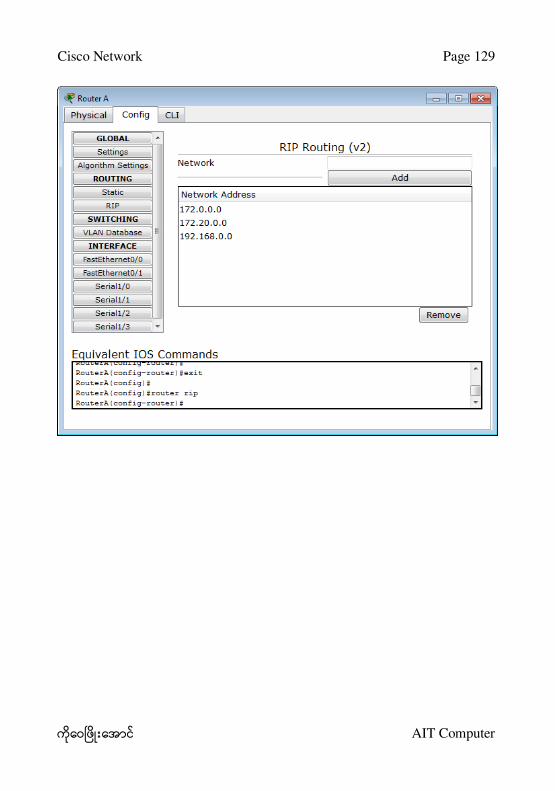
RIP Routing RIP Routing (v2) ။
Cisco Network Page 129
AIT Computer

Cisco Network Page 130
AIT Computer
RIP Route Connection ။
Cisco Network Page 131
AIT Computer
Chapter 20
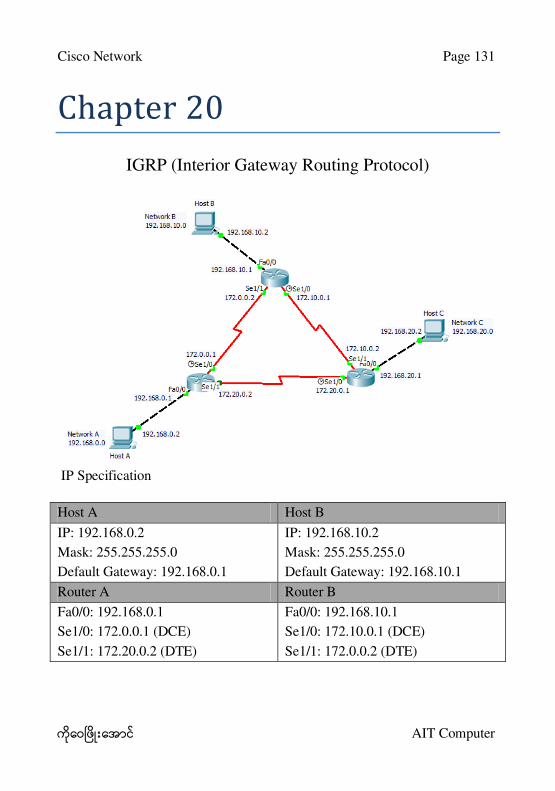
IGRP (Interior Gateway Routing Protocol)
IP Specification
Host A Host B
IP: 192.168.0.2
Mask: 255.255.255.0
Default Gateway: 192.168.0.1
IP: 192.168.10.2
Mask: 255.255.255.0
Default Gateway: 192.168.10.1
Router A Router B
Fa0/0: 192.168.0.1
Se1/0: 172.0.0.1 (DCE)
Se1/1: 172.20.0.2 (DTE)
Fa0/0: 192.168.10.1
Se1/0: 172.10.0.1 (DCE)
Se1/1: 172.0.0.2 (DTE)

Cisco Network Page 132
AIT Computer
Host C
IP: 192.168.20.2
Mask: 255.255.255.0
Default Gateway: 192.168.20.1
Router C
Fa0/0: 192.168.20.1
Se1/0: 172.20.0.1 (DCE)
Se1/1: 172.10.0.2 (DTE)
Route Connection ။

Cisco Network Page 133
AIT Computer
Chapter 21
OSPF (Open Shortest Path First)
IP Specification
Host A Host B
IP: 192.168.0.2
Mask: 255.255.255.0
Default Gateway: 192.168.0.1
IP: 192.168.10.2
Mask: 255.255.255.0
Default Gateway: 192.168.10.1
Router A Router B
Fa0/0: 192.168.0.1
Se1/0: 172.0.0.1 (DCE)
Fa0/0: 192.168.10.1
Se1/0: 172.10.0.1 (DCE)
Se1/1: 172.0.0.2 (DTE)
Host C
IP: 192.168.20.2
Mask: 255.255.255.0
Default Gateway: 192.168.20.1
Router C
Fa0/0: 192.168.20.1
Se1/1: 172.10.0.2 (DTE)

Cisco Network Page 134
AIT Computer
Route Connection ။

Cisco Network Page 135
AIT Computer
Chapter 22
VLAN
IP Address
Computer IP Address Subnet Mask
Aung Aung 192.168.0.1 255.255.255.0
Mg Mg 192.168.0.2 255.255.255.
Hla Hla 172.0.0.1 255.0.0.0
Mya Mya 172.0.0.1 255.0.0.0

Cisco Network Page 136
AIT Computer
၁။ Switch0 ။
၂။ VLAN Database ။
၃။ VLAN Number 10 ။
၄။ VLAN Name MyVan10 ။

Cisco Network Page 137
AIT Computer
၅။ FastEthernet0/1 ။
၆။ VLAN 10 ။
၇။ FastEthernet0/2 10။
၈။ FastEthernet0/3 FastEthernet0/4 20။

Cisco Network Page 138
AIT Computer
VLAN Connection ။
VLAN with Trunk
VLAN Switch Access
Trunk ။
IP Address
Computer IP Address Subnet Mask
Aung Aung 192.168.0.1 255.255.255.0
Mg Mg 192.168.0.2 255.255.255.0
Hla Hla 172.0.0.1 255.0.0.0
Mya Mya 172.0.0.1 255.0.0.0
Tun Tun 192.168.0.3 255.255.255.0
Wai Phyo 192.168.0.4 255.255.255.0
Thu Thu 172.0.0.3 255.0.0.0
Su Su 172.0.0.4 255.0.0.0

Cisco Network Page 139
AIT Computer
Switch Port Trunk ။
VLAN Connection ။