cisco medical-grade network (mgn) 2.0— campus...
TRANSCRIPT

Cisco Medical-Grade Network (MGN) 2.0—Campus ArchitectureLast Updated: September 16, 2010

C O N T E N T SC O N T E N T S
Campus Architecture Overview 8
Protected 9
Interactive 9
Responsive 10
Resilient 10
Healthcare Considerations in the Campus 10
Biomedical Devices 10
Layer-2 Biomedical Device Operation 11
Layer-3 Biomedical Device Operation 12
Hybrid Layer 2/Layer 3 Biomedical Device Operation 12
Clinical Systems and Devices 12
Layer 3 Operation 12
PACS, RIS Systems, and Modalities 13
Layer 3 Operation 13
Regulatory and Security 14
Other Considerations in the Campus 14
Campus Architecture Overview in Healthcare 15
Cisco Campus Architecture Overview 15
Campus Design Options 16
Layer 2 and Layer 3 Designs 17
Designing Highly Available Medical-Grade Campus Networks 18
Overview 18
Campus Architecture Considerations 18
Core Layer 19
Distribution Layer 20
Access Layer 22
Network Redundancy Considerations 24
Chassis-Based Switches 26
Stackable-Based Switches 26
Eliminating Single Points-of-Failure 27
In-the-Box Redundancy (ISSU, NSF and SSO) 28
In-Service Software Upgrades (ISSU) 28
NonStop Forwarding (NSF) and Stateful Switchover (SSO) 29
Best Practices for Optimal Convergence 30
2

C O N T E N T S
IGP/STP Selection 30
IGP (Routing Protocols) 32
STP 35
Achieving Six Sigma Availability 36
Design Option: Virtual Switching System (VSS) 36
Application of VSS 37
Virtual Switching System (VSS) Design 38
Environmental Considerations 42
Power Management 42
PoE 42
Redundant Power 42
Cooling—BTU Management 43
Convergence of Biomedical and General Purpose IT Networks 43
Overview 43
Biomedical Device Dependencies 44
Network Virtualization and Path Isolation 44
GRE Tunneling 46
VRF/VRF-Lite 46
MPLS Campus 46
Overlay Transport Virtualization (OTV) 47
IEC-80001 48
Quality-of-Service (QoS) Considerations 49
What is QoS? 49
QoS Models for Healthcare 50
QoS in Medical-Grade Networks 50
QoS in the Healthcare Campus 51
QoS Model for Medical-Grade Networks 52
Campus QoS Models 52
QoS Classification 52
Medical-Grade Network Applications 55
Voice 57
Video 58
Scavenger Class 58
Guest Traffic 59
3

C O N T E N T S
Biomedical Devices Classification 59
Control Plane Policing 60
AutoQoS 60
Wireless QoS 61
Voice and Collaboration Considerations 62
PoE 63
Cisco UC 8.0 SRND – PoE 64
Cisco Catalyst Switch PoE Support 64
Unified Communications Manager Resiliency 66
Healthcare VoWLAN Considerations 67
Site Surveys 67
Non-802.11 Device Interference 68
VoWLAN QoS 69
Cisco Compatible Extensions 70
Call Admission Control 70
VoWLAN Troubleshooting 70
Multicast 70
Security 71
Unified Secure Voice Messaging 72
Session Manager Edition 73
Unified Communications Endpoints 73
Remote Survivability 74
ISR 74
Voice QoS 75
TelePresence 75
HealthPresence 76
Change Management 76
Management Control Plane 78
Out-of-Band Management Techniques 79
Authentication and Access Control 81
Rapid Fault-Isolation Techniques 83
NTP Sync—PTP 1588 Time Stamping 83
First Failure Analysis—Syslog, SNMP, NetFlow, XML 84
Cisco.com Tools 85
4
C O N T E N T S
Cisco Notification Service 85
TAC Case Collection 85
Output Interpreter 85
Error Message Decoder 85
Bug Toolkit 86
Product Identification Tool 86
Gathering Basic Cisco Call Manager Traces 86
Smart Call Home—Ref 7.7.3 86
Applications 87
OS Tools 87
Embedded Event Manager 87
GOLD 88
Flex Links 89
UDLD 90
Layer 2 Traceroute 90
Smart Install 90
VPC 91
CDP 92
TDR Line Cards 92
Control Plane Policing 92
MLS Rate Limit 93
Management Plane Protection 93
Mini Protocol Analyzer/WireShark 93
SPAN/RSPAN/ERSPAN 94
Enhanced Object Tracking 95
Performance Routing 95
Autostate Messaging (6500) 96
Hardware Components 96
ASIC Thermals 96
Power Management 96
SEA 98
OBFL 99
Core Dump 99
Cisco Advanced Services 99
5

C O N T E N T S
Advanced Services Bug Scrub 99
Code Recommendations 99
Cisco SLA 100
Network Analysis 100
Network Optimization Services (NOS) 101
Cisco Remote Operation Services (CROS) 101
High Touch Technical Services 102
References 102
6

MGN 2.0 Campus Design Architecture
Campus Architecture OverviewThe Cisco Medical-Grade Network (MGN) architecture is based on a set of best practices that apply various foundational network technologies. This document is the third in a series of Cisco MGN 2.0 architecture guides that explores the best practices for campus architectures and technologies that are critical to healthcare environments worldwide. The intent of this document is to present healthcare considerations and design options for architecting a campus healthcare network. The network architect should use Cisco's best practices for campus architectures as a foundation and be aware of the of the many additional considerations for a healthcare environment.
This document is intended for IT and network professionals who are engaged in the design and implementation of healthcare networks in a campus and/or acute care environment. This includes but is not limited to the following:
• Chief Technology Officers (CTOs)
• Chief Information Officers (CIOs)
• Chief Security Officers (CSOs)
• Network and IT directors
• Network integrators
To properly frame the context in which the Cisco MGN 2.0 architecture is based, this document discusses the attributes of a Cisco MGN. An MGN has the following basic characteristics:
• Protected
• Interactive
• Responsive
• Resilient
Corporate Headquarters:
Copyright 2010 Cisco Systems, Inc. All rights re
Cisco Systems, Inc., 170 West Tasman Drive, San Jose, CA 95134-1706 USA

Campus Architecture Overview
ProtectedHealthcare networks world-wide transmit data regarding patients ongoing care, diagnosis, treatment, and financial aspects. From a clinically-focused regulatory perspective, Health Insurance Portability and Accountability Act (HIPAA) is the key legislation in the United States. Globally, other standards exist with much the same intent as HIPAA, but with varying degrees of specificity. These include the Personal Information Protection and Electronic Documents Act (PIPEDA) in Canada and Directive 95/46/EC in the European Union, among others. It is generally accepted that all clinically-focused networks must provide security and protection for sensitive data, both at rest and in transit. Cisco has a variety of security best practices that can be directly applied to help meet the regulatory compliance required by healthcare organizations in all regulatory domains.
Networks can help meet the unique security requirements of healthcare organizations in various ways. Because of this, do not assume that this document, or any of the Cisco MGN architecture guides, dictates the only “approved” method of providing such security measures. This document simply highlights the unique challenges that medical networks face on a global basis, and discusses Cisco best practices to meet these challenges.
Note For more details on Cisco MGN security best practices, refer to the MGN 2.0 Security whitepaper at the following URL: http://www.cisco.com/en/US/docs/solutions/Verticals/Healthcare/MGN_2.0.html
A protected medical network is not simply a set of firewalls at the perimeter of the network, nor does the protection end when the information is written to disk or sent to an offsite vault. An MGN is considered protected when all the industry best practices are applied to the entire healthcare environment.
Security challenges include remote vendor access mechanisms, clinical-workstation host security, and the increasing use of smart phone technology. From a holistic perspective, it is an absolute requirement in all healthcare-focused networks to create a security posture that addresses each of the devices, technologies, and access methods used to transport, store, and access protected health information (ePHI).
Note For more details on the Cisco SAFE architecture, refer to the Cisco SAFE Reference Guide at the following URL: http://www.cisco.com/en/US/docs/solutions/Enterprise/Security/SAFE_RG/SAFE_rg.html
Interactive Care providers interact with patients and clinical staff every minute of the day, in any number of settings. Interactivity in the Cisco MGN provides the ability of the care providers and vendors to interact with the network and its related clinical systems seamlessly. Technologies such as wireless, virtual private network (VPN), and collaborative technologies extend the network into a borderless network.
Examples include a remote clinician who requires immediate access to clinical information, or a remote vendor called in to troubleshoot a medical device that requires specialized diagnostics or corrective action. In these examples, the network provides the fundamental mechanisms and services to provide the level of required interaction, while at the same time providing such access in a highly secure manner, as well as enabling compliancy with local regulatory guidelines and best practices.
8MGN 2.0 Campus Design Architecture
Healthcare Considerations in the Campus
Note Cisco best practices with respect to borderless networks, VPN, remote access, wireless, voice over wireless, video, and so on, are available on the Cisco Design Zone website at the following URL: http://www.cisco.com/en/US/netsol/ns815/networking_solutions_program_home.html
Responsive The term responsive as it relates to the Cisco MGN is often misunderstood as simply a network latency or bandwidth-related concern. Although an MGN must exhibit attributes related to high performance, responsive is not applied in this manner. Instead, it refers to the set of architectural attributes that the network must exhibit to expand and respond to the changing clinical requirements.
To permit the rapid deployment and secure use of various systems, the network must be designed to be elastic from the perspective of security requirements. Otherwise, the adoption of new systems with various unique security policies would be less than optimal.
Resilient For the network engineer, this term typically relates to architectures around that of high availability. Indeed, this is exactly what is required by the industry for any MGN. Such networks are said to be six sigma compliant, or achieve availability of 99.999 percent or better. Achieving such high availability from the perspective of the care provider is sometimes a significant challenge because it means approximately five minutes of downtime per year.
High availability usually results from eliminating a single points-of-failure and networks designed to converge rapidly.
Healthcare Considerations in the CampusHealthcare providers, including acute and ambulatory care facilities, posses a diverse and unique set of endpoints, clinical devices/systems, applications and regulatory requirements that are very different than the standard enterprise facility. These unique requirements influences the design decisions that the healthcare campus architect will be required to make.
Biomedical DevicesBiomedical devices can be classified into different categories or class of devices. There may be a handful of different vendor products and models of devices. Depending on vendor and device model, the campus architecture designs must be tailored to provide the necessary functionality, and to comply with the requirements specified from the medical device vendor.
The following are some examples of typical medical devices used in an acute healthcare setting:
• Patient monitors
• Smart Infusion pumps
• Mobile radiology devices
• Pulse Oximeter Oxygen Saturation Sensors (SPO2)
9MGN 2.0 Campus Design Architecture

Healthcare Considerations in the Campus
Within each distinct device category, there may be a subsystem of servers also used to support the medical devices application. For example, a typical patient monitor system may consist of the following components:
• Bedside monitors
• Patient monitor central station
• Database server
In general, medical devices are embedded systems that are controlled by the device manufacturer. A key design principle for medical devices is to keep them as reliable as possible by reducing the number of unnecessary variables. By implementing only those features that are required by the product, a higher degree of product stability can be achieved. To a certain degree, this has balanced the development cycle of devices, where it is possible that certain Layer-3 routing functions may not be developed on certain medical device platforms.
Due to this approach, some vendors require some network segmentation for their products to work on a campus network. This often manifests itself into special requirements where a particular device platform requires Layer-2 adjacencies to function on the network.
Generally, device life cycles are long (7 to 10 years), and some networked medical device systems include software that was designed to operate on these Layer-2 private networks. However, some patient monitor vendors today support Layer-3 routing and advanced multicast features that make it possible for devices to coexist on a converged IP network.
Some of the main vendors and products in the patient monitoring space include Philips Intellivue, GE Dash, Draeger Infinity, and Welch Allyn Propaq. These vendors support both wireless and wired deployments as part of their overall architecture.
Many medical device vendors also specify latency and jitter requirements on the campus network. In most cases, a reasonable packet latency time and jitter is expected and should be kept to a minimum across the network. For example, some latency times in excess of 25 to 100 ms between any device devices may cause application performance degradation or unpredictable behavior. Generally, jitter should be no greater than 5 percent. Latency and jitter times should be measured on an ongoing basis and under various network load conditions to ensure correct application performance.
In many vendor implementations, the patient monitors must stay in communication with the database servers. If the patient monitors lose communication with the database server for longer than the defined parameter (i.e., 15 to 30 seconds) the central servers may timeout and revert to local monitoring mode, potentially resulting in loss of monitoring at the central stations.
Layer-2 Biomedical Device Operation
Some medical device manufacturers may have strict Layer-2 adjacency requirements. For example, many patient monitors and centralized stations must reside on their own Layer 2 subnet. For these vendors, patient monitors associate to a central station using legacy broadcast methods and do not allow routing between subnets. In some cases, the vendor may require that the network be completely dedicated for the patient monitoring application. This reduces the risk of system performance interruptions caused by other devices residing outside the subnet.
Considerations for Layer-2 adjacency requirement over a converged IT network are scalability, network performance, and path isolation. For more details, refer to the “Convergence of Biomedical and General Purpose IT Networks” section on page 42.
10MGN 2.0 Campus Design Architecture

Healthcare Considerations in the Campus
Layer-3 Biomedical Device Operation
Some medical devices, however, can operate over a Layer-3 routed network. Patient monitor devices vendors that support Layer 3 routing will require that their patient monitor associate to a central station using multicast methods that allows for routing between subnets.
Multicast may be used for IGMP joins and Layer-3 waveform distribution and general topology, and care group association used for “overview” functions. The “overview” session is a window displayed at the bedside that shows the real-time waves, measurements, alerts, etc. for another patient. A user can request an overview session or can permanently configure an overview session.
Unicast traffic can also be used for connection messages for device type, serial numbers, and equipment labeling. Multicast is used for IGMP Layer-3 waveform distribution, general topology, and care group associations generally used for overview sessions.
Hybrid Layer 2/Layer 3 Biomedical Device Operation
A Layer-2/Layer-3 hybrid design is another approach that some medical devices use. Here, devices may operate within a simple routed environment but may have limited multicast functionality or have central stations or database servers that may not be routable. Also, the devices may use a combination of multicast and unicast to operate properly on the network. For example, multicast may be used by the patient monitor to discover the central server, and use unicast to send the wave data to the central station.
In general, medical devices require that the campus network offer an increased level of uptime, a high level of redundancy, minimal level of disruption in the network and in some cases, path isolation to accommodate Layer 2 dependencies. Securing these types of devices on the network and ease of management are also relevant requirements for medical devices.
Clinical Systems and DevicesClinical systems may be comprised of electronic medical records (EMR) systems, backend servers, lab systems, and pharmacy systems. In addition, these clinical systems refer to systems that support clinical workflow and decision support, including EHR and computerized physician order entry (CPOE) systems. Often these systems will include laboratory and pharmacy systems as well as imaging and PACS application.
The EMR system is the clinical repository for the collection of clinical information for the patients under care. Many EHR systems drive the workflows within a healthcare environment, allowing caregivers to streamline patient care with attention to protocol and overall patient care. In many secondary or acute care environments, the EHR system is the focal point of all clinical data that has been collected on the patient.
Layer 3 Operation
Most clinical EHR systems operate over a Layer-3 routed network. These clinical systems often support 802.11 wireless standards as mobile workstation or computers on wheels (CoWs). This allows caregivers to access data at the point of care in many different forms and at various locations. Healthcare professionals can have real-time access to various applications in a clinical information system (CIS).
Some Computerized Physician Order Entry (CPOE) components (for example, from a single vendor) may use a thin client-based delivery system while the medical administration component from the same vendor uses a fat client-based approach.
11MGN 2.0 Campus Design Architecture

Healthcare Considerations in the Campus
EHR systems are comprised of different applications, some developed by different business units within the software vendor, and others acquired through mergers and acquisitions. In general, clinical systems and devices require that the campus network offer an increased level of uptime, especially for their EMR applications. Requirements also include a high level of redundancy, increased throughput, and a minimal level of disruption in the network.
PACS, RIS Systems, and ModalitiesRadiology systems may comprise electronic Picture Archival and Communication (PACS) systems, Radiology Information Systems (RIS), and modalities such as MRI, CT, and ultrasound.
PACS is at the core of medical image management. PACS is comprised of a cluster of an application, database and web servers. The PACS' database is large, and contains the patient image studies. When a modality (MRI, CAT scan, X-ray, ultrasound) acquires an image, it is first viewable on the modality itself, where the radiologist or technologist performing the exam can verify that the image has been properly acquired. The communication of acquired studies is typically transferred over the network using the Digital Imaging and Communications in Medicine (DICOM) protocol.
The RIS is used by radiologists on a daily basis for scheduling the workflow and providing a means for the radiologist to enter a diagnosis into the DICOM study. The RIS function can be built into the diagnostic workstation, which is common with most vendors. Other deployments may separate the DICOM diagnostic workstation/viewer from the RIS.
Layer 3 Operation
Most PACs applications and modalities operate over a Layer-3 routed network. Modalities may often be geographically dispersed away from the PACs servers located in the data center, and connectivity is established over a WAN. Modern imaging requires large amounts of resources because of the size of the images, sometimes in the gigabit range.
The PACS architecture will dictate the quantity and function of the servers, but they all require high availability, typically greater than 99.99%. When more than a single PACS server and/or multiple modalities are present, it is often difficult to provide high availability and fault tolerance. PACS supports centralized image storage for quick image access and retrieval across a distributed storage environment.
The applications of these products are produced through direct consultation with radiology or imaging services providers to address many key concerns as the growth and complexity of imaging services increases exponentially.
PACS, RIS systems, and modalities require that the campus network offer an increased level of uptime, high availability, minimal level of disruption in the network, and increased throughput to handle access to image transfer for storage, archival, and acquisition.
12MGN 2.0 Campus Design Architecture

Healthcare Considerations in the Campus
Regulatory and SecurityWith the dramatic rise in security breaches, theft of patient health data, and the increase in regulatory requirements such as those mandated by the American Recovery and Reinvestment Act of 2009, healthcare organizations and their business partners are now under intense pressure and scrutiny regarding security and privacy. Many regulatory regimes including HIPAA, PCI, and EC 95/46 mandate compliance with specific requirements as part of those regulations. The Cisco MGN security architecture is designed to meet many of these regulatory bodies, not just a singular body1.
With the worldwide focus on electronic health records (EHR), providing meaningful end-to-end security architectures to provide securement to electronic protected health information (ePHI) is crucial for anyone involved in security-related roles within the healthcare enterprise. Security must be considered in the overall design as the dependency on EHR systems increases, as well as the requirement for more efficient workflows that can be implemented without regard to the physical location of the clinician.
Healthcare security business requirements can be boiled down to two main categories: meeting regulatory requirements and protecting patient privacy and safety. Healthcare organizations need to have comprehensive plans around these two areas in order to mitigate security threats. A systems approach to streamline IT risk management for security and compliance is needed.
Local country regulatory compliance and security/privacy require that the campus network offer an increased level of security, access control, authorization, authentication and a high level of visibility/network management.
For more information, refer to the MGN 2.0: Security Architectures whipepaper at the following URL:
http://www.cisco.com/en/US/docs/solutions/Verticals/Healthcare/MGN_2.0.html
Other Considerations in the CampusOther considerations that influence the campus architecture in healthcare are voice and collaboration integration, guest services, and future evolving convergence of biomedical data directly in the EMR system.
Voice and collaboration services use end-to-end Cisco Unified Communication solutions to support unique Cisco solutions such as HMI Collaboration, Nurse Connect, Expert-on-Demand, and HealthPresence. Design considerations should include support for VoWLAN, PoE, QoS, and resiliency. These topics are described in the “Voice and Collaboration Considerations” section on page 61.
Healthcare organizations and ambulatory-based providers are offering guest Internet services to not only their patient community, but students and contractors as well. Providing Internet access to the patient community provides much needed access to the outside world during a time when the individual may need such communication mechanisms. The campus MGN should provide for integration of wireless internet access services. Guest services generally require that the campus network offer an increased level of security, acceptable use policy, posture, and network admission control.
For more information on guest services, refer to the MGN 2.0: Wireless Architectures whipepaper at the following URL.
http://www.cisco.com/en/US/docs/solutions/Verticals/Healthcare/MGN_wireless_adg.html
1. Any specifically applicable regulatory requirements and compliance actions are to be evaluated on an individual basis. Regulatory requirements may vary not only by the specific technology application but also by nation. Cisco Systems makes no representations concerning the extent or nature of regulatory requirements that may be implicated in any given technology application.
13MGN 2.0 Campus Design Architecture

Campus Architecture Overview in Healthcare
Clearly, an emerging trend is the integration of medical device data into clinical systems. Here, medical device data is converted to HL7 or XML format and integrate with any Electronic Medical Record (EMR), Clinical Information Systems (CIS), and/or Alarm and Event Management system to enhance workflow. This would save thousands of nursing hours and improve patient care.
Campus Architecture Overview in HealthcareMultiple technologies are required/combined to create healthcare network infrastructure. These technologies are often deployed independently of one another, which lead to disjointed capabilities, configuration conflicts, and management challenges. Ideally, each of these technologies should integrate into a cohesive network platform capable of delivering network services that are protected, resilient, responsive, and interactive, as discussed above. It is the interconnection and combination of these technologies that provide value and enable clinical and business capabilities in the healthcare environment.
The most basic foundational technologies that enable this interconnection are routing and switching functions. Routing and switching features and protocols are well understood, but the configuration practices and deployment approaches vary from customer to customer based on specific need and design preferences. There are many considerations that factor into routing and switching design and tradeoffs are often required due to the healthcare's unique set of endpoints, clinical applications, and regulatory and privacy requirements.
Unfortunately, in many healthcare environments, legacy application or device support often result in suboptimal designs or redundant overlay networks. As described in the previous section, many of the older biomedical devices had limited networking capabilities and relied on broadcast traffic for communication. This prevents many healthcare organizations from following best practices around the size and scope of Layer 2 networks. Many medical device manufacturers also place support restrictions on their solutions that require dedicated networks for hosting their solutions.
Innovation in biomedical devices and solutions has eliminated some of the legacy networking constraints. This innovation, along with growing customer demand, has forced medical device manufacturers to loosen support restrictions allowing convergence to take place. Multiple biomedical device networks are now converging onto one production network, greatly reducing management overhead, and allowing better use of valuable data which was previously isolated.
This convergence trend does create some new challenges for network designers and support staff. This document discusses some of these challenges and offers some best practice recommendations for designing MGN capable of supporting this convergence.
For more details on biomedical device convergence, refer to the “Convergence of Biomedical and General Purpose IT Networks” section on page 42.
Cisco Campus Architecture Overview
Cisco MGN 2.0 campus architecture is one of the technology modules in the overall Cisco MGN architecture. This section provides an overview of campus design considerations for the campus architecture module within a healthcare environment. Figure 1 illustrates a typical MGN campus architecture. Details about campus access, distribution, and core design considerations are provided in the “Designing Highly Available Medical-Grade Campus Networks” section on page 17.
Design options should be considered when determining the location for shared services (i.e.,Wireless LAN Controllers, NAC Servers, Network Analysis Module (NAM), and IPS). If the campus design calls for a single distribution block, then the services block should connect to the distribution block in a
14MGN 2.0 Campus Design Architecture

Campus Architecture Overview in Healthcare
fully-meshed configuration, to support load balancing and redundancy. For larger networks that require multiple distribution blocks, the service block may be better suited to connect to the core block, rather than the distribution block.
Additionally, if a large distribution block requires increased demand for services, the service modules can be directly integrated into the distribution switches. This option would enable the services to be closer to the edge and users.
Figure 1 Example Campus Architecture for Healthcare
Campus Design OptionsThe use of hierarchical design principles provides the foundation for implementing Medical-Grade campus networks. The hierarchical model can be used to design a modular topology using scalable “building blocks” that allow the network to meet evolving business needs. The modular design makes the network easy to scale, understand, and troubleshoot by promoting deterministic traffic patterns.
Access
Distribution Core
North Access 2
10G
10G
Nx10G
10G
Nx 10G
Nx 10G
Nx 10G
Services Block
NAM
IntrusionPrevention
System
NetworkAnalysisModule
NAC Server
Wireless LANController(s)
IP
South Access 1
South Access 2
North Access 1
PortableUltrasound
SmartInfusion
Pump
ClinicalWorkstation
Cisco7925G
8o2.11nAP
8o2.11nAP
Point ofSale
Device
LWAPP
LWAPP
NursingStation
CT/MR
CoWMedication
Administration Cart
RFIDTag
PatientMonitor
2294
82
TelePresence
15MGN 2.0 Campus Design Architecture
Campus Architecture Overview in Healthcare
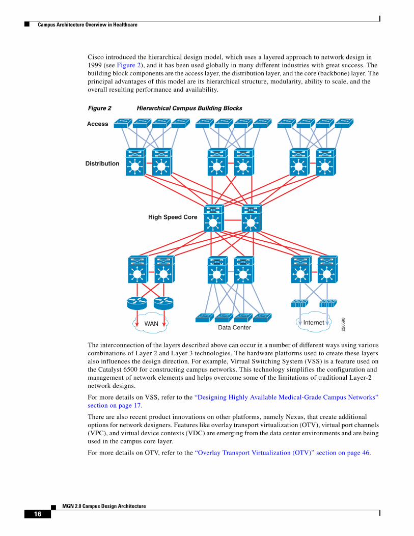
Cisco introduced the hierarchical design model, which uses a layered approach to network design in 1999 (see Figure 2), and it has been used globally in many different industries with great success. The building block components are the access layer, the distribution layer, and the core (backbone) layer. The principal advantages of this model are its hierarchical structure, modularity, ability to scale, and the overall resulting performance and availability.
Figure 2 Hierarchical Campus Building Blocks
The interconnection of the layers described above can occur in a number of different ways using various combinations of Layer 2 and Layer 3 technologies. The hardware platforms used to create these layers also influences the design direction. For example, Virtual Switching System (VSS) is a feature used on the Catalyst 6500 for constructing campus networks. This technology simplifies the configuration and management of network elements and helps overcome some of the limitations of traditional Layer-2 network designs.
For more details on VSS, refer to the “Designing Highly Available Medical-Grade Campus Networks” section on page 17.
There are also recent product innovations on other platforms, namely Nexus, that create additional options for network designers. Features like overlay transport virtualization (OTV), virtual port channels (VPC), and virtual device contexts (VDC) are emerging from the data center environments and are being used in the campus core layer.
For more details on OTV, refer to the “Overlay Transport Virtualization (OTV)” section on page 46.
2205
90
WAN InternetData Center
High Speed Core
Distribution
Access
16MGN 2.0 Campus Design Architecture

Designing Highly Available Medical-Grade Campus Networks
Layer 2 and Layer 3 Designs
As described previously, the interconnection of the layers can occur in a number of different ways using various combinations of Layer 2 and Layer 3 technologies. Biomedical devices, clinical applications, and associated security requirements influence the Layer 2 and Layer 3 designs. An understanding of these unique requirements is necessary to properly design the campus network for the healthcare environment.
Designing Highly Available Medical-Grade Campus Networks
OverviewIn general, high availability of 99.999% and above can only be achieved when hardware redundancy exists in the network and when diagnostics are capable of recognizing a fault condition and failing over to a secondary or load-sharing device. In general, this diagnostic capability is superior at the protocol level with redundant chassis’s, and when the appropriate protocol is properly configured. However, keep in mind that the overall goal is to provide a highly available end-to-end MGN that includes clinical systems and biomedical devices. However, many times, the clinical systems (EHR, EMR, Practice management, Lab, Pharmacy, Radiology, and so on) are not architected to provide 99.999% availability. From the viewpoint of the network infrastructure, however, the following practices are measures of redundancy in a larger network topology:
• No single point-of-failure (redundant chassis', stackable switches) especially towards the core of the network
• Redundant supervisor, fan, and power modules in access layer devices
• Redundant power and fan in core/distribution devices
• Protocols implemented that can quickly detect faults and failover appropriately
• Redundant network services (where access or network capability is limited by a service(e.g., DNS)
Campus Architecture Considerations
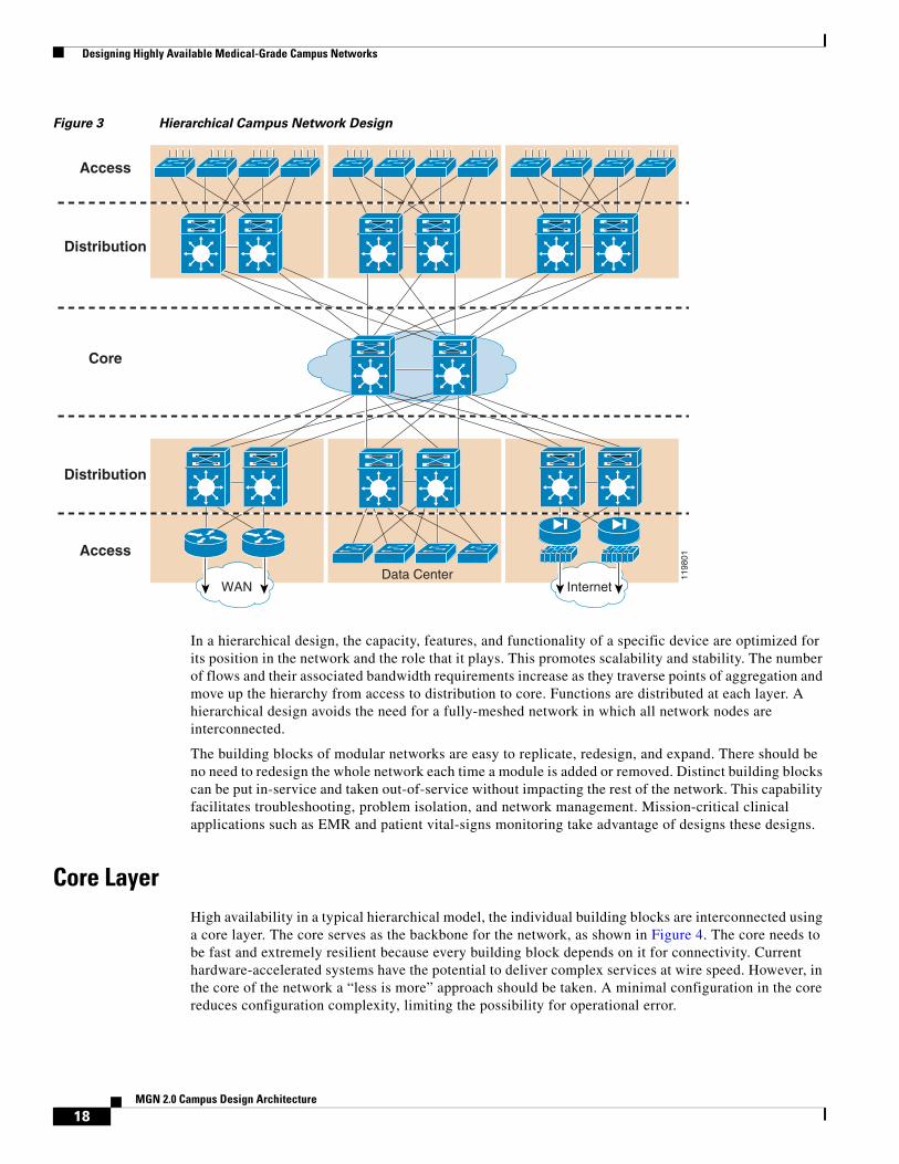
The hierarchical model is used to design a modular topology using scalable “building blocks” that allow the network to meet evolving business needs. The modular design makes the network easy to scale, understand, and troubleshoot by promoting deterministic traffic patterns. Cisco introduced the hierarchical design model, which uses a layered approach to network design in 1999 (see Figure 3), and it has been used globally in many different industries with great success. The building block components are the access layer, the distribution layer, and the core (backbone) layer. The principal advantages of this model are its hierarchical structure, modularity, ability to scale, and the overall resulting performance and availability.
17MGN 2.0 Campus Design Architecture
Designing Highly Available Medical-Grade Campus Networks
Figure 3 Hierarchical Campus Network Design
In a hierarchical design, the capacity, features, and functionality of a specific device are optimized for its position in the network and the role that it plays. This promotes scalability and stability. The number of flows and their associated bandwidth requirements increase as they traverse points of aggregation and move up the hierarchy from access to distribution to core. Functions are distributed at each layer. A hierarchical design avoids the need for a fully-meshed network in which all network nodes are interconnected.
The building blocks of modular networks are easy to replicate, redesign, and expand. There should be no need to redesign the whole network each time a module is added or removed. Distinct building blocks can be put in-service and taken out-of-service without impacting the rest of the network. This capability facilitates troubleshooting, problem isolation, and network management. Mission-critical clinical applications such as EMR and patient vital-signs monitoring take advantage of designs these designs.
Core Layer High availability in a typical hierarchical model, the individual building blocks are interconnected using a core layer. The core serves as the backbone for the network, as shown in Figure 4. The core needs to be fast and extremely resilient because every building block depends on it for connectivity. Current hardware-accelerated systems have the potential to deliver complex services at wire speed. However, in the core of the network a “less is more” approach should be taken. A minimal configuration in the core reduces configuration complexity, limiting the possibility for operational error.
1198
01
WAN InternetData Center
Access
Core
Distribution
Access
Distribution
18MGN 2.0 Campus Design Architecture

Designing Highly Available Medical-Grade Campus Networks
The campus core is the network infrastructure that provides access to network communication services and resources to end users and devices spread over a single geographic location. Its architectural design promotes non-blocking, rapid convergence, and ultra-high nonstop availability. The core is the cornerstone of the entire campus network, providing connectivity between end users including both data center and remote resources.
Figure 4 Core Layer
Although it is possible to achieve redundancy with a fully-meshed or highly-meshed topology, that type of design does not provide consistent convergence if a link or node fails. Also, peering and adjacency issues exist with a fully-meshed design, making routing complex to configure and difficult to scale. In addition, the high port count adds unnecessary cost and increases complexity as the network grows or changes. The following are some of the other key design considerations to in mind.
Design the core layer as a high-speed, Layer-3 switching environment using only hardware-accelerated services. Layer 3 core designs are superior to Layer 2 and other alternatives because they provide the following:
• Faster convergence around a link or node failure.
• Increased scalability because neighbor relationships and meshing are reduced.
• More efficient bandwidth utilization.
• Use redundant point-to-point Layer 3 interconnections in the core (triangles, not squares) wherever possible, because this design yields the fastest and most deterministic convergence results.
• Avoid Layer 2 loops and the complexity of Layer 2 redundancy, such as Spanning Tree Protocol (STP) and indirect failure detection for Layer-3 building block peers.
Distribution Layer The distribution layer acts as a services and control boundary between the access and the core. It layer aggregates nodes from the access layer, protecting the core from high-density peering (see Figure 5).
Additionally, the distribution layer creates a fault boundary providing a logical isolation point in the event of a failure originating in the access layer. Typically deployed as a pair of Layer 3 switches, the distribution layer uses Layer 3 switching for its connectivity to the core of the network and Layer 2 services for its connectivity to the access layer. Load balancing, quality-of-service (QoS), and ease of provisioning are key considerations for the distribution layer.
1198
02
Core
Access
Distribution
19MGN 2.0 Campus Design Architecture

Designing Highly Available Medical-Grade Campus Networks
The distribution layer uses Layer 3 switching for its connectivity to the core of the network and either Layer 2 or Layer 3 services for its connectivity to the access layer. Network services contained within the distribution layer include Wireless LAN controllers, network analysis, network access controllers, and intrusion prevention appliances.
Figure 5 Distribution Layer
High availability in the distribution layer is provided through dual equal-cost paths from the distribution layer to the core and from the access layer to the distribution layer (see Figure 6). This results in fast, deterministic convergence in the event of a link or node failure. When redundant paths are present, failover depends primarily on hardware link failure detection instead of timer-based software failure detection. Convergence based on these functions, which are implemented in hardware, is the most deterministic.
Figure 6 Distribution Layer—High Availability
1198
03
Access
Distribution
1198
01
WAN InternetData Center
Access
Core
Distribution
Access
Distribution
20MGN 2.0 Campus Design Architecture

Designing Highly Available Medical-Grade Campus Networks
Layer 3 equal-cost load sharing allows both uplinks from the core to the distribution layer to be used. The distribution layer provides default gateway redundancy using the Gateway Load Balancing Protocol (GLBP), Hot Standby Router Protocol (HSRP), or Virtual Router Redundancy Protocol (VRRP). This allows for the failure or removal of one of the distribution nodes without affecting endpoint connectivity to the default gateway.
You can achieve load balancing on the uplinks from the access layer to the distribution layer in many ways, but the easiest way is to use GLBP. GLBP provides HSRP-like redundancy and failure protection. It also allows for round-robin distribution of default gateways to access layer devices, so the endpoints can send traffic to one of the two distribution nodes.
Access Layer The access layer is the first point of entry into the network for edge devices such as medical devices, computers on wheels, modalities, end stations, and IP phones (see Figure 7). The switches in the access layer are connected to two separate distribution layer switches for redundancy. If the connection between the distribution layer switches is a Layer 3 connection, then there are no loops and all uplinks actively forward traffic.
The access layer provides the intelligent demarcation between the network infrastructure and the computing devices. It provides a security, QoS, and policy trust boundary and is a key element in enabling multiple services.
Figure 7 Access Layer
A robust access layer provides the following key features:
• High availability (HA) supported by many hardware and software attributes.
• Inline power (PoE) for IP telephony and wireless access points, allowing customers to converge voice onto their data network and providing roaming WLAN access for users.
• Foundation services.
The hardware and software attributes of the access layer that support high availability include the following:
• System-level redundancy using redundant supervisor engines and redundant power supplies. This provides high availability for critical user groups.
• Default gateway redundancy using dual connections to redundant systems (distribution layer switches) that use GLBP, HSRP, or VRRP. This provides fast failover from one switch to the backup switch at the distribution layer.
1198
04Access
Distribution
To Core
21MGN 2.0 Campus Design Architecture
Designing Highly Available Medical-Grade Campus Networks
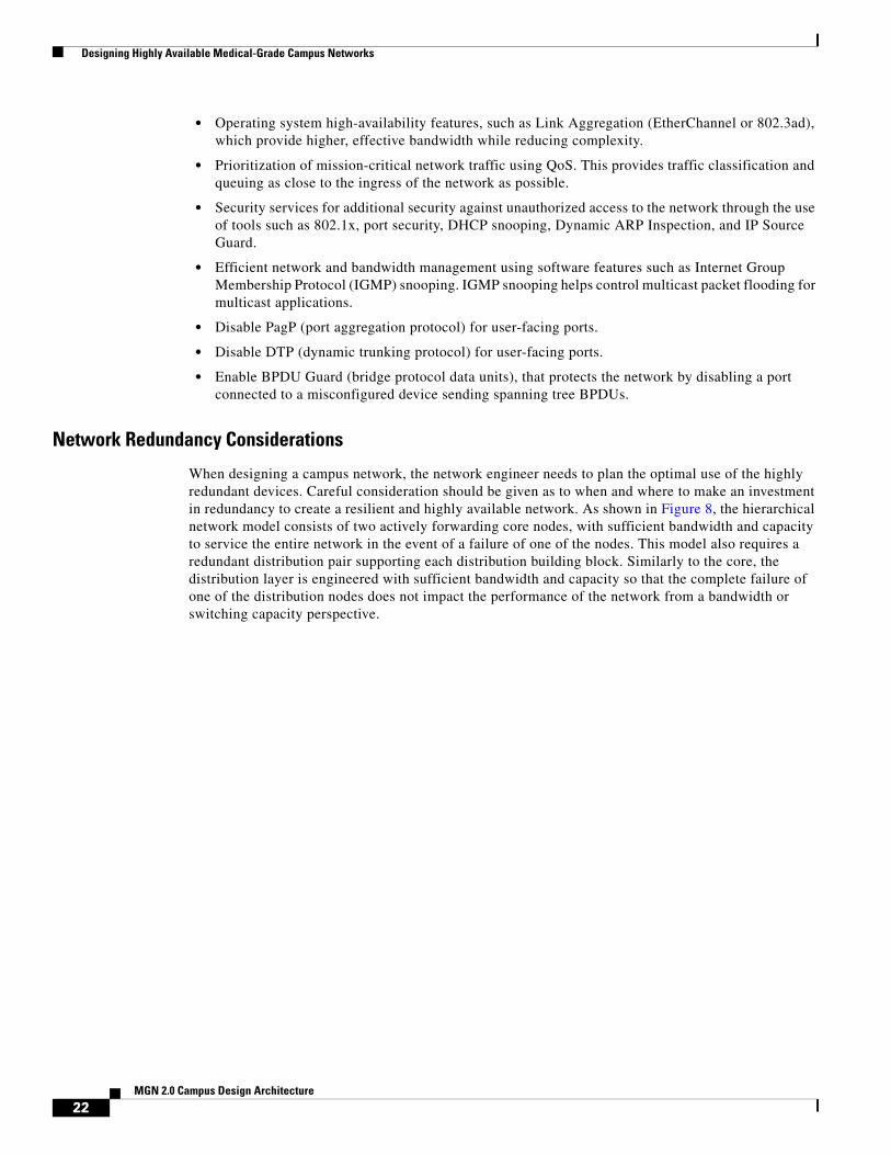
• Operating system high-availability features, such as Link Aggregation (EtherChannel or 802.3ad), which provide higher, effective bandwidth while reducing complexity.
• Prioritization of mission-critical network traffic using QoS. This provides traffic classification and queuing as close to the ingress of the network as possible.
• Security services for additional security against unauthorized access to the network through the use of tools such as 802.1x, port security, DHCP snooping, Dynamic ARP Inspection, and IP Source Guard.
• Efficient network and bandwidth management using software features such as Internet Group Membership Protocol (IGMP) snooping. IGMP snooping helps control multicast packet flooding for multicast applications.
• Disable PagP (port aggregation protocol) for user-facing ports.
• Disable DTP (dynamic trunking protocol) for user-facing ports.
• Enable BPDU Guard (bridge protocol data units), that protects the network by disabling a port connected to a misconfigured device sending spanning tree BPDUs.
Network Redundancy Considerations
When designing a campus network, the network engineer needs to plan the optimal use of the highly redundant devices. Careful consideration should be given as to when and where to make an investment in redundancy to create a resilient and highly available network. As shown in Figure 8, the hierarchical network model consists of two actively forwarding core nodes, with sufficient bandwidth and capacity to service the entire network in the event of a failure of one of the nodes. This model also requires a redundant distribution pair supporting each distribution building block. Similarly to the core, the distribution layer is engineered with sufficient bandwidth and capacity so that the complete failure of one of the distribution nodes does not impact the performance of the network from a bandwidth or switching capacity perspective.
22MGN 2.0 Campus Design Architecture

Designing Highly Available Medical-Grade Campus Networks
Figure 8 Redundant Network Nodes
Campus network devices can currently provide a high level of availability within the individual nodes. The Cisco Catalyst 6500 and 4500 switches can support redundant supervisor engines and provide Layer-2 Stateful Switchover (SSO), which ensures that the standby supervisor engine is synchronized from an Layer 2 perspective and can quickly assume Layer 2 forwarding responsibilities in the event of a supervisor failure.
The Catalyst 6500 also provides Layer-3 Non-Stop Forwarding (NSF), which allows the redundant supervisor to assume Layer-3 forwarding responsibilities without resetting or reestablishing neighbor relationships with the surrounding Layer-3 peers in the event of the failure of the primary supervisor.
When designing a network for optimum high availability, it is tempting to add redundant supervisors to the redundant topology in an attempt to achieve even higher availability. However, adding redundant supervisors to redundant core and distribution layers of the network can increase the convergence time in the event of a supervisor failure.
In the hierarchical model, the core and distribution nodes are connected by point-to-point Layer-3 routed fiber optic links. This means that the primary method of convergence for core or distribution node failure is loss of link. If a supervisor fails on a non-redundant node, the links fail and the network converges around the outage through the second core or distribution node. This allows the network to converge in 60 to 200 milliseconds for EIGRP and OSPF.
When redundant supervisors are introduced, the links are not dropped during an SSO or NSF convergence event if a supervisor fails. Traffic is lost while SSO completes, or indirect detection of the failure occurs. SSO recovers in 1 to 3 seconds, depending on the physical configuration of device in question. Layer 3 recovery using NSF happens after the SSO convergence event, minimizing Layer-3
1199
76
WAN InternetData Center
Access
Core
Distribution
Access
Distribution
RedundantNodes
23MGN 2.0 Campus Design Architecture

Designing Highly Available Medical-Grade Campus Networks
disruption and convergence. For the same events, where 60 to 200 milliseconds of packet loss occurred without redundant supervisors when dual-supervisor nodes were used in the core or distribution, 1.8 seconds of loss was measured.
The access layer of the network is typically a single point-of-failure, as shown in Figure 9.
Figure 9 Potential Single Points-of-Failure
While the access nodes are dual-connected to the distribution layer, it is not typical for endpoints on the network to be dual-connected to redundant access-layer switches (except in the data center). For this reason, SSO provides increased availability when redundant supervisors are used in the access layer and the Layer 2/Layer 3 boundary is in the distribution layer of the network. In this topology, SSO provides for protection against supervisor hardware or software failure with 1 to 3 seconds of packet loss and no network convergence. Without SSO and a single supervisor, devices serviced by this access switch would experience a total network outage until the supervisor was physically replaced or, in the case of a software failure, until the unit is reloaded.
If the Layer 2/Layer 3 boundary is in the access layer of the network, a design in which a routing protocol is running in the access layer, then NSF with SSO provides an increased level of availability. Similarly to the Layer-2/Layer-3 distribution layer topology, NSF with SSO provides 1 to 3 seconds of packet loss without network convergence compared to total outage until a failed supervisor is physically replaced for the routed access topology.
Campus topologies with redundant network paths can converge faster than topologies that depend on redundant supervisors for convergence. NSF/SSO provide the most benefit in environments where single points-of-failure exist. In the campus topology, that is the access layer. If you have a Layer-2 access layer design, redundant supervisors with SSO provide the most benefit. If you have a routed access layer design, redundant supervisors with NSF with SSO provide the most benefit.
1199
77
Access
Core
Distribution
PotentialSingle Points
of Failure
24MGN 2.0 Campus Design Architecture

Designing Highly Available Medical-Grade Campus Networks
Chassis-Based SwitchesCisco chassis-based switches are modular switching platforms that provides the scalability, flexibility, and redundancy required for building large, switched intranets and can be used in both wiring closet and backbone healthcare applications.
Cisco Catalyst switches offer an extremely high level of manageability, security, scalability, and investment protection, resulting in lower total cost-of-ownership (TCO) for wiring closet deployments. With its support for hot-swappable modules, power supplies, and fans, chassis-based switches deliver high availability for healthcare networks. Dual-redundant switching engines, active uplinks, power supplies, and a passive backplane design ensure full system redundancy for mission-critical healthcare environments.
One key advantage with chassis based switches is support for the In-Service Software Updates feature (ISSU) that provides for hitless upgrades. This eliminates downtime associated with software upgrades or version changes by allowing changes while the system remains in service. Dual Supervisor engines also provide Active GbE or 10GbE uplinks which preserves the topology.
Since the switches support discrete line cards, line cards can be replaced (i.e., line card or supervisor) individually and significantly reduce downtime. Also, redundant supervisor engines may be installed to rapidly recover from supervisor failures. Supervisor engines may also be upgraded after purchase, increasing performance and adding new features without losing any investment in the rest of the switch.
Stackable-Based SwitchesCisco Catalyst stackable switches uses Cisco StackWise technology using the capabilities of a stack of switches. Individual switches intelligently join to create a single switching unit with a 32-Gbps switching stack interconnect. Configuration and routing information is shared by every switch in the stack, creating a single switching unit. See Figure 10.
Switches can be added to and deleted from a working stack without affecting performance. These new switches support Cisco EnergyWise technology, which helps companies manage the power consumption of their network infrastructure and network-attached devices, thereby reducing their energy costs and carbon footprints.
http://www.cisco.com/en/US/products/ps5718/Products_Sub_Category_Home.html#~all-prod
Figure 10 Stack-based Switches
The switches are united into a single logical unit using special stack interconnect cables that create a bidirectional closed-loop path. This bidirectional path acts as a switch fabric for all the connected switches. Network topology and routing information is updated continuously through the stack interconnect. All stack members have full access to the stack interconnect bandwidth. The stack is managed as a single unit by a master switch, which is elected from one of the stack member switches.
25MGN 2.0 Campus Design Architecture

Designing Highly Available Medical-Grade Campus Networks
Stackable switches at the access are typically used for small closet areas that serve fewer users and devices. Stackable switches can be easily added to the Stackwise to allow port density growth on an as needed basis. In addition, stackable switches take up less footprint and space and can help resolve some the environmental and power issues that older hospitals face in regards to their access closets.
Eliminating Single Points-of-FailureThe hierarchical network model stresses redundancy at many levels to remove a single point-of-failure wherever the consequences of a failure are serious. At the very least, this model requires redundant core and distribution layer switches with redundant uplinks throughout the design. The hierarchical network model also calls for EtherChannel interconnection for key links where a single link or line card failure can be catastrophic.
When it comes to redundancy, however, you can have too much of a good thing. Take care not to over-duplicate resources. There is a point of diminishing returns when the complexity of configuration and management outweighs any benefit of the added redundancy. See Figure 11.
Figure 11 Over-Duplicated Resources
In Figure 11, the addition of a single switch to a very basic topology adds several orders of magnitude in complexity. This topology raises the following questions:
• Where should the root switch be placed?
• What links should be in a blocking state?
• What are the implications of STP/RSTP convergence?
• When something goes wrong, how do you find the source of the problem?
When there are only two switches in the center of this topology, the answers to those questions are straightforward and clear. In a topology with three switches, the answer depends on many factors.
1198
50
26MGN 2.0 Campus Design Architecture

Designing Highly Available Medical-Grade Campus Networks
However, the other extreme is also a bad thing. You might think that completely removing loops in a topology that requires the spanning of multiple VLANs across access-layer switches might be a good thing. After all, this eliminates the dependence of convergence on STP/RSTP. However, this approach can cause its own set of problems, including the following:
• Traffic is dropped until HSRP becomes active.
• Traffic is dropped until the link transitions to forwarding state, taking as long as 50 seconds.
• Traffic is dropped until the MaxAge timer expires and until the listening and learning states are completed.
In-the-Box Redundancy (ISSU, NSF and SSO)
In-Service Software Upgrades (ISSU)
The ISSU process allows you to perform a Cisco IOS software upgrade or downgrade while the system continues to forward packets. Cisco IOS ISSU eliminates downtime associated with software upgrades or version changes by allowing changes while the system remains in service (see Figure 12). Cisco IOS software high availability features combine to lower the impact that planned maintenance activities have on network service availability, with the results of less downtime and better access to critical systems. It is supported on Cisco 6500 and Cisco 4500 platforms.
SSO mode supports configuration synchronization. When images on the active and standby Route Processors (RPs) are different, this feature allows the two RPs to be kept in synchronization although they may support different sets of commands.
Figure 12 ISSU States During the ISSU Process
1272
57
5Standby
New
ActiveNew
2Standby
New
ActiveOld
Acceptversion
Abortversion
Abortversion
Switchover4
StandbyOld
ActiveNew
3
StandbyOld
ActiveNew
Commitversion Runversion
Loadversion
Commitversion Runversion
Loadversion
1Standby
Old
ActiveOld
27MGN 2.0 Campus Design Architecture

Designing Highly Available Medical-Grade Campus Networks
Prerequisites for Performing ISSU
• Ensure that both the active and the standby RPs are available in the system.
• The new and old Cisco IOS software images must be loaded into the file systems of both the active and standby RPs before you begin the ISSU process.
• Stateful Switchover (SSO) must be configured and working properly. If you do not have SSO enabled, see the Stateful Switchover document for further information on how to enable and configure SSO.
• Nonstop Forwarding (NSF) must be configured and working properly. If you do not have NSF enabled, see the Cisco Nonstop Forwarding document for further information on how to enable and configure SSO.
Use Cisco Feature Navigator to find information about platform support and Cisco IOS software image support. Access Cisco Feature Navigator at http://www.cisco.com/go/fn. You must have an account on Cisco.com. If you do not have an account or have forgotten your username or password, click Cancel at the login dialog box and follow the instructions that appear.
NonStop Forwarding (NSF) and Stateful Switchover (SSO)
The Cisco NonStop Forwarding with Stateful Switchover (SSO) is a supervisor redundancy mechanism in Cisco IOS Software that allows extremely fast supervisor switchover at Layers 2 to 4. Supervisor cards are supported on the Cisco Catalyst 4500 and 6500 product families.
SSO allows the standby RP to take control of the device after a hardware or software fault on the active RP. SSO synchronizes startup configuration, startup variables, and running configuration, and dynamic runtime data. Dynamic runtime data includes Layer-2 protocol states for trunks and ports, hardware Layer 2 and Layer 3 tables (MAC, Forwarding Information Base [FIB], and adjacency tables), access control lists (ACL), and QoS tables. SSO mode supports configuration synchronization. When images on the active and standby RPs are different, this feature allows the two RPs to be kept in synchronization although they may support different sets of commands.
Cisco NSF is a Layer 3 function that works with SSO to minimize the amount of time a network is unavailable to its users following a switchover. The main objective of Cisco NSF is to continue forwarding IP packets following an RP switchover. Cisco NSF is supported by the EIGRP, OSPF, For example, NSF allows the redundant supervisor to assume Layer-3 forwarding responsibilities without resetting or reestablishing neighbor relationships with the surrounding Layer-3 peers in the event of the failure of the primary supervisor A router running System-to-Intermediate System (IS-IS), and Border Gateway Protocol (BGP) protocols can detect an internal switchover and take the necessary actions to continue forwarding network traffic using Cisco Express Forwarding (CEF) while recovering route information from the peer devices. With Cisco NSF, peer networking devices continue to forward packets while route convergence completes and do not experience routing flaps.
28MGN 2.0 Campus Design Architecture

Designing Highly Available Medical-Grade Campus Networks
Best Practices for Optimal Convergence
IGP/STP Selection
The many potential advantages of using a Layer-3 access design include the following:
• Improved convergence
• Simplified multicast configuration
• Dynamic traffic load balancing
• Single control plane
• Single set of troubleshooting tools (for example, ping and traceroute)
Of these, perhaps the most significant is the improvement in network convergence times possible when using a routed access design configured with EIGRP or OSPF as the routing protocol. Comparing the convergence times for an optimal Layer 2 access design (either with a spanning tree loop or without a loop) against that of the Layer 3 access design, you can obtain a four-fold improvement in convergence times, from 800-900msec for the Layer 2 design to less than 200 msec for the Layer 3 access. (See Figure 13.)
Figure 13 Comparison of Layer 2 and Layer 3 Convergence
Although the sub-second recovery times for the Layer-2 access designs are well within the bounds of tolerance for most enterprise networks, the ability to reduce convergence times to a sub-200 msec range is a significant advantage of the Layer-3 routed access design. To achieve the convergence times in the Layer 2 designs shown above, you must use the correct hierarchical design and tune HSRP/GLBP timers in combination with an optimal Layer-2 spanning tree design. This differs from the Layer 3 campus,
1484
21
0
200
400
600
800
1000
1200
1400
1600
1800
2000
Max
imu
m V
oic
e L
oss
(m
sec.
)
OSPF L3 AccessL2 802.1w & OSPF L2 802.1w & EIGRP EIGRP L3 Access
29MGN 2.0 Campus Design Architecture

Designing Highly Available Medical-Grade Campus Networks
where it is necessary to use only the correct hierarchical routing design to achieve sub-200 msec convergence. The routed access design provides for a simplified high availability configuration. The following section discusses the specific implementation required to meet these convergence times for the EIGRP and OSPF routed access design.
Note For additional information on the convergence times, see the High Availability Campus Recovery Analysis design guide, located at the following URL: http://www.cisco.com/en/US/netsol/ns815/networking_solutions_program_home.html.
Only use Layer-2 looped topologies if it cannot be avoided. In general practice, the most deterministic and best-performing networks in terms of convergence, reliability, and manageability are free from Layer-2 loops and do not require STP to resolve convergence events under normal conditions. However, STP should be enabled to protect against unexpected loops on the access or user-facing interfaces.
In the reference hierarchical design, Layer-2 links are deployed between the access and distribution nodes. However, no VLAN exists across multiple access layer switches. Additionally, the distribution-to-distribution link is a Layer-3 routed link. This results in a Layer-2 loop-free topology in which both uplinks from the access layer are forwarding from an Layer-2 perspective and are available for immediate use in the event of a link or node failure (see Figure 14).
Figure 14 Layer 2 Loop-Free Topology
For STP design and deployment and configuration, refer to the Campus Network High Available Design Guide at the following URL:
http://www.cisco.com/en/US/docs/solutions/Enterprise/Campus/HA_campus_DG/hacampusdg.html
IGP (Routing Protocols)
Both small and large enterprise campuses require a highly available, intelligent network infrastructure with securement to support business solutions such as voice, video, wireless, and mission-critical data applications. The use of hierarchical design principles provides the foundation for implementing campus networks that meet these requirements. The hierarchical design uses a building block approach leveraging a high-speed routed core network layer to which multiple independent distribution blocks are attached. The distribution blocks comprise of two layers of switches: the actual distribution nodes that act as aggregators and the wiring closet access switches.
1198
18
Access
Distribution
Layer 3
Layer 2 links
HSRP model
HSRP ActiveVLAN 20,140
Layer 2 links
HSRP ActiveVLAN 40,120
10.1.20.010.1.120.0
VLAN 20 DataVLAN 120 Voice
10.1.40.010.1.140.0
VLAN 40 DataVLAN 140 Voice
30MGN 2.0 Campus Design Architecture

Designing Highly Available Medical-Grade Campus Networks
In larger IP environments, Cisco recommends that most enterprise organizations standardize on OSPF, ISIS, or EIGRP for IP routing. These protocols support variable length subnet mask (VLSM), summarization, and enhanced feature capabilities, including routing protocol safeguards. A lack of routing standardization can result in poor routing hierarchy, poor convergence times, added complexity, and poor manageability.
IP routing protocol hierarchy is an extension of normal device hierarchy that adds resiliency to IP routing.
• Creating routing domains and summarizing contiguous IP blocks towards the core of the network can accomplish IP routing hierarchy.
• OSPF forces hierarchy by requiring well-defined routing areas.
• Larger IP networks may also have an additional core IP layer configured using the BGP protocol to help scale the environment and to help contain routing problems due to link/device instability or device resource limitations.
Summarization is a key aspect of IP routing protocol design that helps reduce required routing resource requirements and reduces or prevents the affect of link flapping on routing protocol cores. Summarization also helps reduce link overhead on WAN links that can be a significant amount of traffic over a WAN connection.
• IP networks with over 1000 subnets should have well defined areas with IP summarization towards the core of the network. This summarization is normally configured at OSPF area boundaries or distribution router interfaces connected to the network core.
• Networks with over 1000 routes should consider stub routing for access sites or routing filters to advertise major network blocks and/or default routes.
• Larger scale IP networks with over 5000 subnets should consider a BGP core to limit routing protocol overhead. The need for a BGP core should be closely examined and weighed against adding summarization and routing protocol safeguards to the existing IGP (interior gateway protocol) routing domain.
• IP Summarization should also be examined for WAN access sites to reduce routing protocol overhead on network devices and network links.
Routing protocol safeguards are configurable, protective mechanisms that prevent routes from being readvertised back into the originating domain. Routing protocol safeguards prevent WAN sites from advertising routes back into the core, and protect against routing protocol configuration mistakes, such as accidentally advertising the default route into the core from a WAN location.
• Route filters should be configured on the appropriate interfaces to protect against bogus routes and non-originating routes.
• In LAN environments another safeguard is to configure passive-interface on access VLANs to prevent core routing across user or server subnets and to generally reduce routing protocol overhead where it is not required.
HSRP is a software feature that permits redundant IP default gateways on server and client subnets. On user or server subnets that require default gateway support, HSRP provides increased resiliency by providing a redundant level-3 IP default gateway. In redundant user and server subnets HSRP should be configured in a manner optimal for the particular environment.
In the typical hierarchical campus design, distribution blocks use a combination of Layer 2, Layer 3, and Layer 4 protocols and services to provide for optimal convergence, scalability, security, and manageability. In the most common distribution block configurations, the access switch is configured as a Layer 2 switch that forwards traffic on high speed trunk ports to the distribution switches. The
31MGN 2.0 Campus Design Architecture

Designing Highly Available Medical-Grade Campus Networks
distribution switches are configured to support both Layer 2 switching on their downstream access switch trunks and Layer 3 switching on their upstream ports towards the core of the network, as shown in Figure 15.
Figure 15 Traditional Campus Design Layer 2 Access with Layer 3 Distribution
The function of the distribution switch in this design is to provide boundary functions between the bridged Layer 2 portion of the campus and the routed Layer 3 portion, including support for the default gateway, Layer-3 policy control, and all the multicast services required.
Note Although access switches forward data and voice packets as Layer 2 switches, in the Cisco campus design they use advanced Layers 3 and 4 features supporting enhanced QoS and edge security services.
An alternative configuration to the traditional distribution block model illustrated above is one in which the access switch acts as a full Layer-3 routing node (providing both Layer 2 and Layer 3 switching), and the access-to-distribution Layer-2 uplink trunks are replaced with Layer 3 point-to-point routed links. This alternative configuration, in which the Layer 2/3 demarcation is moved from the distribution switch to the access switch (as shown in Figure 16) appears to be a major change to the design, but is actually simply an extension of the current best practice design.
Core
Access
Distribution
VLAN 3 VoiceVLAN 103 Data
VLAN 2 VoiceVLAN 102 Data
VLAN n VoiceVLAN 100 + n Data 13
2702
Layer 3
Layer 2
HSRP ActiveRoot Bridge
HSRPStandby
32MGN 2.0 Campus Design Architecture

Designing Highly Available Medical-Grade Campus Networks
Figure 16 Routed Access Campus Design—Layer 3 Access with Layer 3 Distribution
In both the traditional Layer 2 and the Layer 3 routed access design, each access switch is configured with unique voice and data VLANs. In the Layer 3 design, the default gateway and root bridge for these VLANs is simply moved from the distribution switch to the access switch. Addressing for all end stations and for the default gateway remain the same. VLAN and specific port configuration remains unchanged on the access switch. Router interface configuration, access lists, “ip helper”, and any other configuration for each VLAN remain identical, but are now configured on the VLAN Switched Virtual Interface (SVI) defined on the access switch, instead of on the distribution switches. There are several notable configuration changes associated with the move of the Layer 3 interface down to the access switch:
• It is no longer necessary to configure an HSRP or GLBP virtual gateway address as the “router” interfaces for all the VLANs are now local.
• Similar with a single multicast router, for each VLAN it is not necessary to perform any of the traditional multicast tuning such as tuning PIM query intervals or to ensure that the designated router is synchronized with the active HSRP gateway.
For details on Configuraiton Layer 3 access, refer to the following URL:
http://www.cisco.com/en/US/docs/solutions/Enterprise/Campus/HA_campus_DG/hacampusdg.html
STP
Highly available networks require redundant paths to ensure connectivity in the event of a node or link failure. Various versions of Spanning Tree Protocol (STP) are used in environments that include redundant L2 loops. STP lets the network deterministically block interfaces and provide a loop-free topology in a network with redundant links
Figure 17 STP Operation
Core
Access
Distribution
VLAN 3 VoiceVLAN 103 Data
VLAN 2 VoiceVLAN 102 Data
VLAN n VoiceVLAN 00 + n Data 13
2703
Layer 3
Layer 2
1198
17
STOPA
B
33MGN 2.0 Campus Design Architecture

Designing Highly Available Medical-Grade Campus Networks
Network hierarchy and redundancy will not improve availability if the network protocol design does not meet Cisco leading-practices. Cisco supports a generous assortment of protocols and features; however, the two protocols that have the greatest potential impact to overall network availability are the spanning tree protocol for LAN environments at Layer 2, and IP at Layer 3. Other protocols and features that pertain to improved network availability include hot standby routing protocol (HSRP), stateful switchover (SSO), and nonstop forwarding (NSF).
STP at Layer 2 is designed to support failover recovery at the device level due to link or device failures. Spanning tree can be left at a default configuration; however this can often lead to sub-optimal convergence and potential loop conditions. The biggest problem with spanning tree domains is the failure to identify a loop condition, which generally results in a loss of multiple devices within the spanning tree domain until the devices are rebooted and the condition repaired.
The best spanning tree domains with the highest availability tend towards fewer devices with more stringent spanning tree configuration templates. For user access devices with non-redundant access connectivity, simple spanning tree domains of one access device and two redundant distribution links and devices is recommended. For servers with dual NICs a larger spanning tree domain is required with an additional access device. In addition, the following spanning tree configuration steps or features are generally recommended. Keep in mind that a Cisco design review is always recommended to identify leading-practices for any individual design topology.
• Configure the root bridge at the distribution level
• Configure only Layer 3 between distribution switches unless HA servers are required with connections to multiple access switches.
• Configure RPVST+ within loop spanning tree domains.
• Consider the Root Guard feature.
• Disable PagP (port aggregation protocol) for user-facing ports.
• Disable DTP (dynamic trunking protocol) for user-facing ports.
• Enable BPDU Guard (bridge protocol data units), that protects the network by disabling a port connected to a misconfigured device sending spanning tree BPDUs.
Achieving Six Sigma AvailabilityHighly available networks are a combination of well-designed networks, thoughtfully implemented processes and procedures and a robust set of tools for proactively managing the network environment. Table 1 highlights the timescales associated with high availability.
For a service to be “six-sigma”, it can only be unavailable for 31.53 seconds every year. Multiplied by the number of services, number of users, and the number of devices in a given network, managing to sustain a “six-sigma” network is a daunting and resource-intensive task.
Table 1 High Availability Time Scales
Availability Downtime Per Year
99.9% 8.76 hours (31536 seconds)
99.99% 52.56 minutes (3153.6 seconds)
99.999% (five-9s) 5.25 minutes (315.36 seconds)
99.9999% (six-sigma) 31.53 seconds
34MGN 2.0 Campus Design Architecture

Designing Highly Available Medical-Grade Campus Networks
Achieving such high availability from the care provider’s perspective is sometimes a significant challenge as it equates to approximately 5 minutes of downtime per year.
Within data centers that host EMR/EHR systems, such availability at the network layer can indeed be achieved. In some cases, however, the applications used to support the clinical staff are simply not architected to achieve this level of availability and often result in downtimes from the caregiver’s perspective that well exceeding these goals. These outages are mainly due to software upgrades or patches being applied, or in some cases upstream systems such as payers or external testing labs.
Design Option: Virtual Switching System (VSS) Virtual Switching System or VSS enables unprecedented functionality and availability of healthcare campus networks by integrating network and systems redundancy into a single node. The end-to-end healthcare network enabled with VSS capability allows flexibility and availability described in this document.
The single logical node extends the integration of services in a healthcare campus network beyond what has been previously possible, without significant compromise. Integration of wireless, Firewall Services Module (FWSM), Intrusion Prevention System (IPS), and other service blades within the VSS allow for the adoption of an array of service ready for campus design capabilities. For example, VSS implementation allows for the applications of Internet-edge design (symmetric forwarding) and data center interconnection (loop-less disaster recovery). Though this document only discusses the application of VSS in a healthcare campus at the distribution layer, it is up to the network designer to adapt the principles illustrated in this document to create new applications and not limit the use of VSS to the campus environment.
The key underlying capability of VSS is that it allows the clustering of two physical chassis together into a single logical entity. See Figure 18.
Figure 18 Conceptual Diagram of VSS
This virtualization of the two physical chassis into a single logical switch fundamentally alters the design of campus topology. One of the most significant changes is that VSS enables the creation of a loop-free topology. In addition, VSS also incorporates many other Cisco innovations—such as Stateful Switch Over (SSO) and Multi-chassis EtherChannel (MEC)—that enable nonstop communication with increased bandwidth to substantially enhance application response time. Key business benefits of the VSS include the following:
• Reduced risk associated with a looped topology
• Nonstop business communication through the use of a redundant chassis with SSO-enabled supervisors
• Better return on existing investments via increased bandwidth form access layer
Switch 1 + Switch 2
Virtual Switch Domain
VirtualSwitch Link
= VSS–SingleLogical Switch 22
7020
35MGN 2.0 Campus Design Architecture

Designing Highly Available Medical-Grade Campus Networks
• Reduced operational expenses (OPEX) through increased flexibility in deploying and managing new services with a single logical node, such as network virtualization, Network Admission Control (NAC), firewall, and wireless service in the campus network
• Reduced configuration errors and elimination of First Hop Redundancy Protocols (FHRP), such as Hot Standby Routing Protocol (HSRP), GLBP, and VRRP
• Simplified management of a single configuration and fewer operational failure points
In addition, the ability of the VSS to integrate services modules, bring the full realization of the Cisco campus fabric as central to the services-oriented campus architecture.
Application of VSS
Application of VSS in a multilayer design can be used wherever the need of Layer-2 adjacency is necessary, not just for application but for flexibility and practical use of network resources. Some of the use cases are as follows:
• Medical devices and applications requiring Layer-2 adjacency. data VLANs spanning multiple access-layer switches
• Simplifying Layer-2 connectivity by spanning VLANs per building or location
• Network virtualization (patient and guest VLAN supporting transient connectivity, healthcare partner, and payor connectivity)
• Conference, media room and public access VLANs spanning multiple facilities
• Network Admission Control (NAC) VLAN (quarantine, posture, and patching) for patient guest services and visiting physicians/clinicians who use their smart phones and laptop computers
• Partner (payor) resources requiring spanned VLANs
• Wireless VLANs without centralized controller
• Network management and monitoring (SNMP, SPAN)
VSS boosts nonstop communications through:
• Interchassis stateful failover results in no disruption to applications that rely on network state information (for example, forwarding table info, NetFlow, Network Address Translation [NAT], authentication, and authorization). VSS eliminates L2/L3 protocol reconvergence if a virtual switch member fails, resulting in deterministic subsecond virtual switch recovery.
• EtherChannel (802.3ad or Port Aggregation Protocol (PAgP) for deterministic subsecond Layer-2 link recovery, removing the dependency on Spanning Tree Protocol (STP) for link recovery.
On the access side of VSS, downstream devices still connect to both physical chassis, but Multichassis EtherChannel (MEC) presents the virtual switch as one logical device. MEC links can use industry-standard 802.1ad link aggregation or port aggregation protocol. Either way, MEC eliminates the need for spanning tree. All links within a MEC are active until a circuit or switch failure occurs, and then traffic continues to flow over the remaining links in the MEC.
On the core side of VSS, devices also use MEC connections to attach to the virtual switch. This eliminates the need for redundancy protocols such as HSRP or VRRP, and also reduces the number of routes advertised. As on the access side, traffic flows through the MEC in an “active/active” pattern until a failure, after which the MEC continues to operate with fewer elements. For more information refer to the following document:
http://www.cisco.com/en/US/docs/solutions/Enterprise/Campus/VSS30dg/campusVSS_DG.html
36MGN 2.0 Campus Design Architecture

Designing Highly Available Medical-Grade Campus Networks
Virtual Switching System (VSS) Design
To better understand the application of the VSS to the campus network, it is important to adhere to existing Cisco architecture and design alternatives. This section illustrates the scope and framework of Cisco campus design options and describes how these solve the problems of high availability, scalability, resiliency, and flexibly. It also describes the inefficiency inherent in some design models.
The process of designing a healthcare campus architecture is challenged by clinical application, high availability, and security requirements. The need for nonstop communication is becoming a basic starting point for most healthcare networks. The business case and factors influencing these designs are discussed in following design framework:
Enterprise Campus 3.0 Architecture: Overview and Framework http://www.cisco.com/en/US/docs/solutions/Enterprise/Campus/campover.html
VSS at the Distribution Block
The Campus 3.0-design framework covers the functional use of a hierarchy in the network in which the distribution block architecture (also referred as access-distribution block) governs a significant portion of campus design focus and functionality. The access-distribution block comprises two of the three hierarchical tiers within the multi-tier campus architecture: the access and distribution layers. While each of these two layers has specific services and feature requirements, it is the network topology control plane design choices (the routing and spanning tree protocols) that are central to how the distribution block is glued together and how it fits within the overall architecture. There are two basic design options for how to configure the access-distribution block and the associated control plane:
• Multilayer or multi-tier (Layer 2 in the access block)
• Routed access (Layer 3 in the access block)
While these designs use the same basic physical topology and cabling plant, there are differences in where the Layer-2 and Layer-3 boundaries exist, how the network topology redundancy is implemented, and how load balancing works, along with a number of other key differences between each of the design options. Figure 19 depicts the existing design choices available.
Figure 19 Traditional Design Choices
L3 CoreNSF/SSO
L3 Distribution NSF/SSO
Multilayer Design Routed Access Design
L3 Access4500 and 6500
NSF/SSO
L2 Access4500 and 6500
SSO
L2 Access3750/3750EStackwise
L3 Access3750/3750EStackwise
+ NSF
2269
14
37MGN 2.0 Campus Design Architecture

Designing Highly Available Medical-Grade Campus Networks
The multilayer design is the oldest and most prevalent design in customer networks while routed access is relatively new. The most common multilayer design consists of VLANs spanning multiple access-layer switches to provide flexibility for applications requiring Layer-2 adjacency (bridging non-routable protocols) and routing of common protocol, such as IPX and IP. This form of design suffers from a variety of problems, such as instability, inefficient resources usage, slow response time, and difficulty in managing end host behavior. See Figure 20.
Figure 20 Multilayer Design—Looped Topology
In the second type of multilayer design, VLANs do not span multiple closets. In other words VLAN = Subnet = Closet. This design forms the basis of the best-practice multilayer design in which confining VLANs to the closet eliminate any potential spanning tree loops (see Figure 21). However, this design does not allow for the spanning of VLANs. As an indirect consequence, most legacy networks have retained a looped Spanning Tree Protocol (STP)-based topology—unless a network topology adoption was imposed by technology or business events that required more stability, such as implementation of voice over IP (VoIP).
Loop Free TopologyAll VLANs spans All Access-switches 22
6915
VLAN 10 VLAN 10VLAN 10
VLAN 20 VLAN 20VLAN 20
Core
L2
38MGN 2.0 Campus Design Architecture
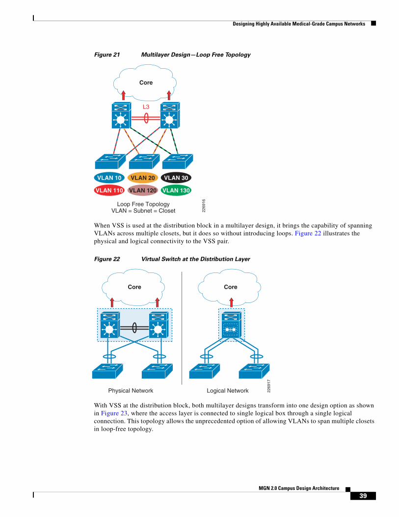
Designing Highly Available Medical-Grade Campus Networks
Figure 21 Multilayer Design—Loop Free Topology
When VSS is used at the distribution block in a multilayer design, it brings the capability of spanning VLANs across multiple closets, but it does so without introducing loops. Figure 22 illustrates the physical and logical connectivity to the VSS pair.
Figure 22 Virtual Switch at the Distribution Layer
With VSS at the distribution block, both multilayer designs transform into one design option as shown in Figure 23, where the access layer is connected to single logical box through a single logical connection. This topology allows the unprecedented option of allowing VLANs to span multiple closets in loop-free topology.
Loop Free TopologyVLAN = Subnet = Closet 22
6916
VLAN 20 VLAN 30VLAN 10
VLAN 120 VLAN 130VLAN 110
Core
L3
Physical Network 2269
17
Logical Network
Core Core
39MGN 2.0 Campus Design Architecture

Designing Highly Available Medical-Grade Campus Networks
Figure 23 VSS-Enabled Loop-Free Topology
The application of VSS is wide ranging. VSS application is possible in all three tiers of the hierarchical campus—core, distribution, and access—as well as the services block in both multilayer and routed-access designs. However, the scope of this document is intended as an application of VSS at the distribution layer in the multilayer design. It also explores the interaction with the core in that capability. Many of the design choices and observations are applicable in using VSS in routed-access design, because it is a Layer-3 end-to-end design. However, the impact of VSS in multilayer is the most significant because VSS enables a loop-free topology along with the simplification of the control plane and high availability.
In summary, VSS provides the following key benefits to healthcare providers:
• Eliminates the need for existing gateway redundancy protocols such as HSRP/VRRP/GLBP.
• Multichassis EtherChannel (MEC) is a Layer-2 multipathing technology that creates simplified loop-free topologies, eliminating the dependency on Spanning Tree Protocol, which may also be activated to protect strictly against any user misconfiguration. VSS uses EtherChannel (802.3ad or Port Aggregation Protocol (PAgP) for deterministic sub second Layer-2 link recovery, removing the dependency on Spanning Tree Protocol for link recovery.
• Enables true server high availability. Servers are connected via a MEC link, with at least 2 Gb of bandwidth. Provides fault tolerance benefits as well. Enables standards-based link aggregation for the server network interface cards (NIC Teaming) across redundant data center switches, maximizing server bandwidth throughput and increasing the number of standards-based components in the data center and eliminates the requirement to configure proprietary NIC vendor availability mechanisms.
• Reduced network management. Less links, fewer peering relationships to manage, and one configuration file to manage. Single point of management, IP address, and routing instance for the VSS switch. Removes the need to configure redundant switches twice with identical policies.
• Enhance fast software upgrades (EFSUs). Allows you to upgrade the code on your core network equipment, with very minimal impact to the users.
VSS Loop Free TopologyVLANs spans Access-switches 22
6918
VLAN 10 VLAN 10VLAN 10
VLAN 20 VLAN 20VLAN 20
Core
40MGN 2.0 Campus Design Architecture

Designing Highly Available Medical-Grade Campus Networks
• Flexible deployment options. The underlying physical switches do not have to be collocated. The two physical switches are connected with standard 10-Gigabit Ethernet interfaces and as such can be located any distance based on the distance limitation of the chosen 10-Gigabit Ethernet optics.
• Interchassis stateful failover results in no disruption to applications that rely on network state information (for example, forwarding table information, NetFlow, Network Address Translation [NAT], authentication, and authorization). VSS eliminates L2/L3 protocol reconvergence if a virtual switch member fails, resulting in deterministic sub-second virtual switch recovery.
• Conserves bandwidth by eliminating unicast flooding caused by asymmetrical routing in traditional campus designs and optimizes the number of hops for intra campus traffic using multichassis EtherChannel enhancements.
• VSS leverages existing multilayer switching architecture. VSS enhances our customers existing multilayer switching architecture by simplifying and maintaining the fundamental architecture, resulting in an easy adoption of the technology.
Environmental ConsiderationsEnvironmental aspects are another network design element that must be considered. As with any highly available network, single points-of-failure should be eliminated if at all possible. Loss of power is a potential point-of-failure and probably one of the most common causes of network outages.
Power ManagementHealthcare environments have some unique requirements due to the nonstop operations of many healthcare facilities and the criticality of the mission at hand. Backup generators are typically deployed in acute care settings, but often in a limited fashion. These generators often do not have the capacity to support the entire facility for a reasonable amount of time, so certain areas are deemed critical and protected while other areas are left unprotected. Understanding these restrictions and protecting the appropriate network equipment to maintain critical network services is very important.
PoE
Power over Ethernet (PoE) is increasingly being used in healthcare environments to support the explosion of wireless access points and IP-based communication systems. Although aggregate power may not change substantially during steady state operation, the distribution points and backup provisions may change substantially. Wiring closets with a high concentration of PoE ports will require more AC circuit capacity and backup provisions then a lightly loaded closet. The number of Uninterruptible Power Supply (UPS) units scattered across a facility may be reduced as more devices shift to PoE and use a more centralized UPS approach within the wiring closets.
Redundant Power
Redundancy can be achieved by leveraging network devices with dual-power supply capabilities and UPS equipment and/or backup generators where feasible.
41MGN 2.0 Campus Design Architecture
Convergence of Biomedical and General Purpose IT Networks
Cooling—BTU Management
Equipment cooling must also be considered. As power distribution shifts to wiring closets the heat generated in the wiring closet increases as well. Many wiring closets were not originally designed to handle the power load and dissipate the heat generated in a PoE environment. Data centers and larger wiring closets (main distribution facilities (MDF)) are often well engineered to handle power and cooling requirements, but smaller closets (intermediate distribution facilities (IDF)) are often overlooked.
Convergence of Biomedical and General Purpose IT Networks
OverviewThere is a growing trend that is focused on the convergence of biomedical and general purpose IT networks. This trend is driven by the need to manage the growing costs of healthcare through leveraging the reliability, high availability, and speed of a well designed IT network.
In the past, all biomedical devices lived on dedicated networks and frequencies. Often these networks did not have connectivity to IT resources and usage of IT networks for biomedical device needs was not a viable option. These biomedical networks often were so specialized and expensive, they often did not require high availability because the bedside was the most important functionality.
Today, vendors have the same cost-cutting concerns and are often in other lines of business where they touch IT networks. Over time, these biomedical devices have adopted IP stack support and are using traditional LAN/WAN network and traditional wireless frequencies.
Medical devices used in healthcare provide a wide variety of function from monitoring, notification, and delivery of medicine. Most of these devices often are under restrictions from regulatory bodies or other such public agencies, which restrict the modification in any way except as governed by a defined regulatory process1. The end result may be very dated and unpatched operating systems running mission critical systems.
This unpatched device, now on an IT network (due to the convergence), creates a hole or path to which a worm, virus, or bot can take hold and being infected is not the end all, but how it affects these critical systems. Most of the systems end up unavailable or unable to report back to central stations.
When building networks that house not only IT or general purpose machines but also healthcare or biomedical devices, there are tools and architectures that lend them to be reliable, highly available with securement.
1. For example, a device classified as falling under US Food and Drug Administration regulation may likely require the device manufacturer's validation testing of safety and effectiveness, and, regulatory body notification / approval prior to a modification being allowed for deployment into the field. Such testing, notification / approval may require a manufacturer's significant investments in time and resources.
42MGN 2.0 Campus Design Architecture

Convergence of Biomedical and General Purpose IT Networks
Biomedical Device DependenciesBiomedical devices such as patient monitoring (PM), ventilators, and infusion pumps are the fastest growing population of network connected devices (wired or wireless) in the provider space. For example, some larger healthcare providers expect to have 150,000 biomedical devices on the converged IP network in the next 3 to 4 years. Medical Device Manufacturer's (MDMs) continue to introduce devices that are IP-enabled and this trend continues to pick up momentum. Hospitals use a variety of these biomedical devices.
Today, however, many biomedical devices require Layer-2 support to communicate back to their associated backend server or central station. In this case, patient monitors and centralized stations must reside on their own dedicated Layer-2 subnet. In some cases, the vendor also requires that the network be completely dedicated for the patient monitoring application. This reduces the risk of system performance interruptions caused by other devices residing outside the subnet. As increasingly number of biomedical devices become IP-enabled, hospitals are looking at ways converge these devices onto to their IT converged network.
Network Virtualization and Path IsolationNetwork virtualization (see Figure 24) and path isolation is critical to building a campus architecture inclusive of biomedical devices that is highly available, reliable, and secure. While trunking Layer 2 VLANs throughout the converged IT network is possible, it is not a viable option when promoting a reliable, scalable network.
Figure 24 Example of the Many-to-One Mapping of Virtual to Physical Networks
2210
35
Virtual Network
Physical Network Infrastructure
Virtual Network Virtual Network
43MGN 2.0 Campus Design Architecture

Convergence of Biomedical and General Purpose IT Networks
Path isolation solutions (see Figure 25) use a mix of Layer 2 and Layer 3 technologies to best address LAN virtualization for typical LAN designs. Cisco offers the following path isolation options:
• Generic routing encapsulation (GRE) tunnels create closed user groups on the hospital LAN. This might be used to provide for L2 connectivity for centralized medical device servers to other remote servers/databases.
• Virtual routing and forwarding (VRF)-Lite, also called Multi-VRF Customer Edge, is a lightweight version of MPLS. VRF-Lite allows network managers to use a single routing device to support multiple virtual routers. They can then use any IP address space for any given VPN, regardless of whether it overlaps or conflicts with other VPNs' address spaces.
• Multiprotocol label switching (MPLS) VPNs also partition a campus network for closed user groups. In the past, MPLS was not widely deployed in enterprise networks because of the lack of support on LAN switches. With the introduction of the Cisco Catalyst 6500 Series, MPLS technology is now affordable for healthcare facilities.
• Overlay Transport Virtualization (OTV) is a feature of the Nexus OS operating system that encapsulates Layer-2 Ethernet traffic within IP packets, allowing Ethernet traffic from a local area network (LAN) to be tunneled over an IP network to create a “logical data center” spanning several data centers in different locations. This is an emerging technology that may have benefits in the future for providing path isolation. For details about OTV, refer to the “Overlay Transport Virtualization (OTV)” section on page 46.
Figure 25 Functional Elements Needed in Virtualized Campus Networks
For further detail about individual technologies, refer to the Network Virtualization—Path Isolation Design Guide at the following URL:
http://www.cisco.com/en/US/docs/solutions/Enterprise/Network_Virtualization/PathIsol.html
2210
36
GRE
VRFs
MPLS
Access Control
Functions
Path Isolation Services Edge
Branch - Campus WAN – MAN - Campus
Authenticate client (user,device, app) attempting togain network access
Authorize client into aPartition (VLAN, ACL)
Deny access to unauthorized clients
Maintain traffic partitioned overLayer 3 infrastructure
Transport traffic over isolated Layer 3 partitions
Map Layer 3 Isolated Path to VLANs in Access and Services Edge
Provide access to services: Shared Dedicated
Apply policy per partition
Isolated application environmentsif necessary
Data Center - Internet Edge -Campus
IP
LWAPP
44MGN 2.0 Campus Design Architecture

Convergence of Biomedical and General Purpose IT Networks
GRE Tunneling
Generic routing encapsulation (GRE) is a tunneling protocol used to transport packets from one network through another network. Some medical device manufacturers have used GRE tunneling in converged networks to allow Layer-2-based medical device applications to communicate with the discrete medical devices, over Layer-3 routed networks.
VRF/VRF-Lite
Virtual Routing and Forwarding (VRF) is a technology that allows multiple instances of a routing table to coexist within the same router at the same time. Because the routing instances are independent, the same or overlapping IP addresses can be used without conflicting with each other.
VRF or VRF-Lite are two methods of virtualizing the network and providing path isolation.
The simplest form of VRF implementation is VRF-Lite. In this implementation, each router within the network participates in the virtual routing environment in a peer-based fashion. While simple to deploy and appropriate for small-to-medium enterprises and shared data centers, VRF-Lite does not scale to the size required by large hospitals, because there is the need to implement each VRF-instance on every router. See Figure 26.
Figure 26 VRF and VRF-Lite
MPLS Campus
Multiprotocol Label Switching (MPLS) VPN is a path isolation option inside the healthcare network to logically isolate traffic between devices belonging to separate groups (i.e., medical devices and patient care devices).
The main advantage of MPLS VPN when compared to other path isolation technologies is the capability of dynamically providing any-to-any connectivity without facing the challenges of managing many point-to-point connections (as for example is the case when using GRE tunnels). MPLS VPN facilitates full mesh of connectivity inside each provided segment (or logical partition) with the speed of provisioning and scalability found in no other protocol. In this way, MPLS VPN allows the consolidation of separate logical partitions into a common network infrastructure.
CampusCore
VRF Blue
VRF Red
VRF Green
VLAN 21 RedVLAN 22 GreenVLAN 23 Blue 22
6031
L3Si Si
Layer 2Trunks
Layer 2Trunks
45MGN 2.0 Campus Design Architecture

Convergence of Biomedical and General Purpose IT Networks
Any Transport over MPLS (AToM) transports datalink layer (Layer 2) packets over the MPLS backbone. AToM enables providers to connect sites with existing Layer 2 networks by using the Cisco MPLS network. Instead of using separate Layer 2 networks, providers can deliver Layer 2 connections over an MPLS backbone. AToM provides a common framework to encapsulate and transport supported Layer-2 traffic types over an MPLS network core. For more details, refer to the following URL:
http://www.cisco.com/en/US/docs/ios/12_0s/feature/guide/fsatom26.html
Overlay Transport Virtualization (OTV)
Overlay transport virtualization or OTV is a Layer-2 extension technology with all the benefits of being Layer 2 adjacency without all the headaches of extending Layer 2 across Layer 3 boundaries.
OTV is an emerging technology that significantly simplifies extending Layer 2 applications across distributed data centers. With OTV you can deploy virtual computing resources and clusters across geographically distributed data centers, delivering transparent workload mobility, business resiliency, and superior computing resource efficiencies. Key OTV features include the following:
• Extends Layer 2 LANs over any network—Uses IP-encapsulated MAC routing, works over any network that supports IP, designed to scale across multiple data centers
• Simplifies configuration and operation—Enables seamless deployment over existing network without redesign, requires minimal configuration commands (as few as four), provides single-touch site configuration for adding new data centers
• Increases resiliency—Preserves existing Layer 3 failure boundaries, provides automated multihoming, and includes built-in loop prevention
• Maximizes available bandwidth—Uses equal-cost multipathing and optimal multicast replication
Note Currently, OTV is only supported on the Nexus 7000 product family.
OTV is simply a MAC in IP technology that is available on the Nexus 7000 platform. This technology uses ISIS behind the scenes and is simple to configure. See Figure 27.
46MGN 2.0 Campus Design Architecture

Convergence of Biomedical and General Purpose IT Networks
Figure 27 OTV Overview
OTV is an emerging technology that may be useful for healthcare where applications are controlled by healthcare vendors or FDA, requiring Layer 2 adjacency. Figure 28 provides a simple example of how OTV works.
Figure 28 How OTV Works
OTV
East Site
OTV
Communication betweenMAC1 (West) and MAC2 (East)
Encapsulate
2294
50
IP BIP AOTV
West Site
Ethernet Frame Ethernet FrameEthernet FrameIP Packet
Dencapsulate
MAC1 Eth1MAC2 IP BMAC3 IP B
MAC100100100
VLAN IFMAC1 IP AMAC2 Eth1MAC3 Eth2
MAC100100100
VLAN IF
East
West
South-East
Core
2294
51
IP A
IP B
OTV update is replicatedby the Core
IP C
MAC1 IP AMAC2 IP AMAC3 IP A
MAC100100100
VLAN IF
MAC1MAC2MAC3
VLAN 100VLAN 100VLAN 100
3 New MACs are learned on VLAN 100
MAC1 IP AMAC2 IP AMAC3 IP A
MAC100100100
VLAN IF
QFP
QFP QFP
QFP
QFP
QFP
OTV
Upd
ate
OTV Update
OTV U
pdate
47MGN 2.0 Campus Design Architecture

Quality-of-Service (QoS) Considerations
Step 1 Three new MAC addresses are learned.
Step 2 OTV update replicated via multicast.
Step 3 OTV update received by other switches.
Step 4 Three new MAC addresses are installed in the table of the other OTV switches and this establishes Layer 2 connectivity across a Layer 3 cloud.
IEC-80001
When biomedical devices are converged onto what is classified as a general purpose IT network, patient safety risks must be considered. The proposed voluntary standard (IEC-80001-1) defines a methodology to identify risks associated with such converged architectures and provides guidance in identifying, tracking and mitigating such risks.
The proposed standard is expected to be ratified in Q4-2010. Three parties are identified with specific roles and responsibilities. These include the following:
• Responsible Organization (RO) (the Healthcare Delivery Organization)—Responsible for the overall risk management process.
• Information Technology Providers (the IT Device Vendor)—Provides the RO with technical descriptions and documentation of the IT device, recommended product configuration, known incompatibilities and restrictions, operating requirements, cyber security notices and known product corrective actions and recalls. Supplementary information may also include test strategies and test acceptance, disclosure of failure modes, reliability statistics, safety cases and performance characteristics.
• Medical device manufacturers (the Medical Device Vendor)—Provides documentation to the RO as to intended use and provides instructions necessary for safe and effective use of their medical devices.
Due to the fact that the network now has a contributing factor in overall patient safety, the IEC-80001-1 proposed standard mandates the use of strict change control policies. By architecting a campus network with high levels of availability and thus minimizing the impacts due to a component or link failure, overall patient care can be improved. These architectural approaches are key to meeting the overall intentions of the IEC-80001-1 proposed standard.
Quality-of-Service (QoS) Considerations
What is QoS?QoS is the measure of transmission quality and service availability of a network (or internetworks). Traffic on IP networks competing for constrained transmission bandwidth and equipment processing time may experience packet loss, packet delay, and variance in packet delay referred to as jitter. Packet loss, delay, and jitter will have a negative, if not debilitating, affect on applications. They may interrupt or stop realtime communications such as voice or video and slow down or break data applications.
Routers and switches provide a set of QoS tools to provide a consistent application experience throughout a range of traffic conditions. The QoS toolset cannot ensure that all applications will work on any network regardless of traffic demands. Network architects and operators must engineer the
48MGN 2.0 Campus Design Architecture

Quality-of-Service (QoS) Considerations
network to meet the bandwidth and delay requirements of the applications and continue to monitor utilization to ensure that the network grows to meet increasing business demands. Provided the network has sufficient capacity to meet those demands, QoS tools will ensure that applications work as designed during the variable bursts of application traffic.
The three primary QoS tools are classification, queuing, and rate limiting. Classification identifies traffic and marks packets (typically using Differentiate Services Code Point (DSCP)) to provide a common identification method and to ensure consistent treatment throughout the network. Queuing controls how much of each type of traffic is transmitted by each node and which traffic is prioritized. Rate limiting uses traffic policing or traffic shaping to enforce how much of each type of traffic may be transmitted.
For a more detailed explanation of these QoS fundamentals and terms, refer to the “Quality-of-Service Design Overview” chapter of the Enterprise QoS Solution Reference Network Design Guide, Version 3.3 at the following URL:
http://www.cisco.com/en/US/docs/solutions/Enterprise/WAN_and_MAN/QoS_SRND/QoS-SRND-Book.html
QoS Models for Healthcare
QoS in Medical-Grade Networks
As the healthcare industry continues to spend millions of dollars to converge medical systems onto a common network with ubiquitous access to information, the potential for network congestion and application failures rises. There are different types of traffic that are simultaneously delivered over the converged Medical-Grade network. This may include the following:
• Clinical Applications
– Patient Electronic Medical Records
• Medical Devices
– Vital signs waveforms (patient monitors)
– Telemetry, measurement data, and alerts
– Specialized vitals applications
– Formulary updates (smart infusion pumps)
• PACS
– Radiology images
– DICOM
• Voice
– IP Telephony (wired and wireless)
• Video and Collaboration
– Telepresence
– Healthpresence
– Webex and Collaboration Tools
– Collaborative care video
– Digital Media Systems (DMS)
– Patient bedside services and entertainment
49MGN 2.0 Campus Design Architecture
Quality-of-Service (QoS) Considerations
– IP Surveillance
• Network Control Protocols
– Routing Protocols
• Device Control Protocols
– DICOM
– HL7
– IP Call Setup
• Guest Services
– Internet Access
– Visiting Physician/Clinician access
• Standard IT Traffic
– FTP, HTTP, DNS, etc.
QoS is critically important to maintaining good application performance and user experience for applications relying on the network.
QoS in the Healthcare Campus
Since network performance issues arise from bottlenecks in the network caused either by low bandwidth links or underpowered network devices, most enterprise QoS deployments focus on the WAN. There are several reasons that Cisco recommends a network-wide QoS strategy for the healthcare campus Medical-Grade network.
• New biomedical, video, and other data-intensive applications are increasing bandwidth demands and creating a higher potential for congestion in the LAN.
• Classification at the access port is more accurate, provides a consistent policy treatment throughout the network and provides greater insight into network performance.
• Multilayer switching devices perform QoS tasks in hardware and remove this processing task from many WAN edge devices that perform these tasks in software.
• Access layer QoS can police unwanted traffic at the source rather than allowing it to traverse the network.
• Campus QoS enables Control Plane Policing (CoPP) features to protect network devices from security and rogue traffic risks.
Cisco is continuing to improve a wide set of QoS tools to simplify the design, deployment, and operation of QoS in both the LAN and WAN. For a more detailed explanation of QoS in the campus, refer to the Medianet Campus QoS Design 4.0 at the following URL:
http://www.cisco.com/en/US/docs/solutions/Enterprise/WAN_and_MAN/QoS_SRND_40/QoSCampus_40.html
Wireless network access is a logical extension of the wired campus network and should be included in the QoS strategy. Wireless networking presents unique the following challenges for QoS:
• Wireless devices are accessing the network through a shared medium, the radio frequency spectrum.
• Wireless access is significantly slower than wired access and is a more likely bottleneck.
• Radio frequency interference can come from a variety of outside sources and further restrict network access.
50MGN 2.0 Campus Design Architecture
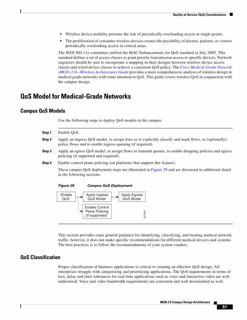
Quality-of-Service (QoS) Considerations
• Wireless device mobility presents the risk of periodically overloading access at single points.
• The proliferation of consumer wireless devices creates the possibility of doctors, patients, or visitors periodically overloading access in critical areas.
The IEEE 802.11e committee ratified the MAC Enhancements for QoS standard in July 2005. This standard defines a set of access classes to grant priority transmission access to specific devices. Network engineers should be sure to incorporate a mapping in their designs between wireless device access classes and wired device classes to achieve a consistent QoS policy. The Cisco Medical-Grade Network (MGN) 2.0—Wireless Architectures Guide provides a more comprehensive analysis of wireless design in medical grade networks with some attention to QoS. This guide covers wireless QoS in conjunction with the campus design.
QoS Model for Medical-Grade Networks
Campus QoS Models
Use the following steps to deploy QoS models in the campus:
Step 1 Enable QoS.
Step 2 Apply an ingress QoS model, to assign trust or to explicitly classify and mark flows, to (optionally) police flows and to enable ingress queuing (if required).
Step 3 Apply an egress QoS model, to assign flows to transmit queues, to enable dropping policies and egress policing (if supported and required).
Step 4 Enable control plane policing (on platforms that support this feature).
These campus QoS deployment steps are illustrated in Figure 29 and are discussed in additional detail in the following sections.
Figure 29 Campus QoS Deployment
This section provides some general guidance for identifying, classifying, and treating medical network traffic; however, it does not make specific recommendations for different medical devices and systems. The best practices is to follow the recommendations of your system vendors.
QoS Classification
Proper classification of business applications is critical to creating an effective QoS design. All enterprises struggle with categorizing and prioritizing applications. The QoS requirements in terms of loss, delay and jitter tolerances for real-time applications such as voice and interactive video are well understood. Voice and video bandwidth requirements are consistent and well documented as well.
EnableQoS
Apply IngressQoS Model
Enable ControlPlane Policing(if supported)
Apply EgressQoS Model
2270
53
51MGN 2.0 Campus Design Architecture

Quality-of-Service (QoS) Considerations
Data applications can be less easy to characterize. It would be easy to say that most every application in a medical facility holds some information that could affect the life or welfare of a patient; however, the reality is that if every application is top priority, then none is. It is important to recognize that while some applications are very important to the business, they are often less sensitive to delay than others. E-mail is a good example. Users rarely know if an E-mail is delayed by 20 seconds because of a burst of traffic generated by a higher priority application.
Enterprise and service provider network QoS design follows the IP Differentiated Services (DiffServ) QoS model which is a class based model for managing traffic. Traffic is categorized using the DSCP field of the IP header and each piece of networking equipment treats that traffic with a policy called a Per Hop Behavior (PHB). To help define a consistent experience across diverse networks, Cisco co-authored RFC 4595 (Configuration Guidelines for DiffServ Service Classes), which is the generally accepted standard for traffic classification and PHB.
Figure 30 depicts the RFC 4595 application categories, their DSCP classified PHB, common enterprise applications in each PHB, whether that application will typically be seen at the access layer of the network and whether that application’s self-classification can be trusted.
Figure 30 Campus Ingress Edge Marking and Trust Categories
Figure 31 summarizes the trust, marking, policing and queuing boundaries for each port type in the campus network. Once the correct trust and marking is done at the access edge, interswitch links in the campus network simply trust the DSCP markings and do policing and queuing where appropriate.
2294
54
Application Class
Transactional Data AF2
Realtime Interactive CS4
VoIP Telephony EF
Ops/Admin/Mgmt (OAM) CS2
Bulk Data AF1
Scavenger CS1
Network Control CS6
Multimedia Streaming AF3
Best Effort DF
Multimedia Conferencing AF4
Broadcast Video CS5
Call-Signaling CS3
(Optional) PQ
BW Queue + DSCP WRED
BW Queue
BW Queue
BW Queue
BW Queue + DSCP WRED
(Optional) PQ
Priority Queue (PQ)
Queuing and Dropping
Min BW Queue (Deferential)
Required
Required
Required
Required
Recommended
AdmissionControl
Per-HopBehavior
BW Queue + DSCP WRED
BW Queue + DSCP WRED
Default Queue + RED
Cisco TelePresence™
Cisco Digital Media System (VoDs)
EIGRP, OSPF, BGP, HSRP, IKE
SCCP, SIP, H.323
SNMP, SSH, Syslog
Cisco Unified Personal Communicator
Cisco IP Video Surveillance/Cisco Enterprise TV
Cisco IP Phones (G.711, G.729)
Application Examples
YouTube, iTunes, BitTorrent, Xbox Live
Cisco WebEx®™/MeetingPlace®/ERP Apps
E-mail, FTP, Backup Apps, Content Distribution
Default Class
52MGN 2.0 Campus Design Architecture

Quality-of-Service (QoS) Considerations
Figure 31 Campus QoS Port Roles
CoreAccess
Trusted Endpoints
Distribution
ConditionallyTrusted Endpoints
Untrusted Endpoints
IP
229455
Conditionally-Trusted Endpoint Port QoS:• Conditional-Trust with
Trust-DSCP• [Optional Ingress Marking/
Policing]• 1P3QyT Queuing
Switch-to-Switch/Router Port QoS:• Trust DSCP• 1P3QyT or 1P7QyT Queuing
Untrusted Endpoint Port QoS:• No Trust• [Optional Ingress Marking/
Policing]• 1P3QyT Queuing
Trusted Endpoint Port QoS:• Trust-DSCP• [Optional Ingress Marking/
Policing]• 1P3QyT Queuing
IP
53MGN 2.0 Campus Design Architecture

Quality-of-Service (QoS) Considerations
Medical-Grade Network ApplicationsThe transition from a dedicated medical device network to a converged hospital network has introduced a wide variety of biomedical and clinical hosts onto the network. Network administrators need to understand the application requirements for each of these devices and applications to correctly categorize them.
Ultimately, a proper risk analysis will help uncover the criticality of the system. A full risk analysis requires an understanding of the system's network requirements. Once that is clear, the risk analysis should focus on the system's normal operation, its behavior under degraded network performance conditions (either caused by network congestion or partial failure) and its behavior under network failure conditions. Understanding these modes of operation and their impact on medical operations will help appropriately classify the application on the network. Consider a couple of example applications.
Patient monitoring such as ventilators or ECG tools now provide waveform feeds or other data streams to nurse stations. Many of these data feeds can require relatively low bandwidth, constant bit-rate streams similar to voice traffic. Interruptions in the data feed may not directly impact patients' health, but they could lead to false alarms, extra work for the medical staff, distrust of the system displays and potentially affect the desired level of patient care. The low bandwidth, constant bit-rate traffic is something potentially suitable to priority queuing. The considerations for priority queuing are discussed below. In general, AF3 (specifically AF31) is most appropriate for biomedical telemetry streaming.
Consider medical imaging as another example. Image studies are increasing in volume and complexity, overburdening existing infrastructure and archive resources. For example, Computed Tomography (CT) scans are now hundreds of megabytes compared to 20 megabytes just a few years ago, consuming more application, network, and storage services. In addition, today's broadly distributed imaging services can be a multi-vendor PACS with an environment of silos of image data. Imaging modalities and infrastructures often reside in multiple disparate systems that are not integrated and do not provide a patient centric view of imaging. This makes it very challenging for any clinician or technologist to easily access all of the studies for patients in a timely fashion. Unlike real-time video applications, PACS images are not degraded delay, jitter, and packet loss. Degraded network performance does impact the timely transmission and display of these images among different locations in the medical campus. It is important to understand the extent of this delay and its impact to medical operations. Severe network congestion delaying an image one minute to a doctor who is preparing for rounds the next morning is reasonably understood to have a different impact as compared to a delay in delivering information that is needed for urgent patient care.
We recommend working closely with the device or application vendor to understand the nature of the system’s network traffic and its behavior under congested (delay, jitter, and packet loss) conditions. Figure 32 depicts a sample proposed classification strategy for medical applications.
54MGN 2.0 Campus Design Architecture

Quality-of-Service (QoS) Considerations
Figure 32 Sample Medical Application Classification
Note that only constant bit-rate traffic can be placed in the priority queue. Note the following key points about priority queuing:
• There is only one priority queue. You can create several queues to feed into it for administrative purposes, but all priority traffic goes to one forwarder.
• Giving the priority queue unlimited bandwidth can starve and break other non-priority applications. Because of this, in some cases, the priority queue is automatically rate-limited to the configured bandwidth.
Because of these conditions, it is recommended that only constant bit-rate traffic be placed in the priority queue. Bursty traffic placed in the priority queue could either break other applications or get dropped when the priority queue is rate-limited.
As long as access to the higher priority multimedia queues is appropriately controlled, applications classified in the transactional and bulk data queues will receive appropriate priority over best effort traffic. It is recommended that you determine which applications need to be prioritized in these queues. Biomedical telemetry streaming applications are more latency sensitive and could be marked as AF31 in the multimedia streaming queue. Additionally, it is recommended to spend the time on determining what applications should have restricted access to the network and should be placed in the savenger class. For details about the scavenger class, refer to the “Scavenger Class” section on page 57.
Note The classifications above are based on general campus QoS guidelines, Refer to the individual vendor's endpoint/device classification recommendations when designing an end-to-end QoS strategy.
One potential concern with the chart in Figure 32 above is the use of Weighted Random Early Drop (WRED) in classes that are carrying medical data. This implies that medical traffic may get dropped, but it is important to understand how and why this happens. WRED is a congestion avoidance protocol. It attempts to avoid network congestion by selectively dropping packets from TCP flows at certain queue
2294
56
Application Class
Transactional Data AF2
Realtime Interactive CS4
Ops/Admin/Mgmt (OAM) CS2
Bulk Data AF1
Scavenger CS1
Network Control CS6
Multimedia Streaming AF3
Best Effort DF
Multimedia Conferencing AF4
Broadcast Video CS5
Call-Signaling CS3
(Optional) PQ
BW Queue + DSCP WRED
BW Queue
BW Queue
BW Queue
BW Queue + DSCP WRED
(Optional) PQ
Queuing and Dropping
Min BW Queue (Deferential)
Per-HopBehavior
BW Queue + DSCP WRED
BW Queue + DSCP WRED
Default Queue + RED
*Biomedical Telemetry Streaming
VoIP Telephony EF Priority Queue (PQ) Constant Bit Rate Biomed Feeds
Medical Applications
Guest Traffic
*Biomedical Devices, Critical Apps, Webex
PACS, Large File Apps
Back Office, Archiving, Patient Records
Cisco Unified Personal Communicator
Cisco Healthpresence, TelePresence
55MGN 2.0 Campus Design Architecture

Quality-of-Service (QoS) Considerations
thresholds as opposed to dropping all arriving traffic indiscriminately when congestion occurs. Dropping a TCP packet during a high traffic period causes that sender to automatically slow down and reduce the potential for congestion. Weighting in WRED means that the network node is more likely to drop a lower priority packet.
WRED works on a per queue basis, so the weighting is significant only if there are multiple DSCP values present in the queue. For example, if your network uses all 12 classifications shown in Figure 32 above, certain network hardware (such as switch line cards with four hardware queues) needs to place multiple classes in the same queue. The 12-to-4 queue mapping model places AF2 through AF4 in the same queue. Since there are only four queues, WRED is the mechanism that gives multimedia traffic preferential treatment over transactional data in the case of network congestion. In a queue servicing only a single traffic class, WRED drops a few packets from selected flows, at a specific threshold, to avoid being forced to drop several packets from many flows after the queue is full. This action minimizes the impact of congestion and permits the remaining flows to transmit at full rate to optimize network utilization.
Voice
IP Telephony deployments are commonplace in medical facilities. All new telephony installations are IP based and many installed TDM systems have been replaced or are scheduled to be replaced soon. The QoS requirements for voice are well understood. The QoS requirements for voice are summarized below. For more detailed information, refer to the VoIP section of the “Quality of Service Design Overview” chapter of the Enterprise QoS Solution Reference Network Design Guide Version 3.3 at the following URL:
http://www.cisco.com/en/US/docs/solutions/Enterprise/WAN_and_MAN/QoS_SRND/QoS-SRND-Book.html
There are two components to VoIP traffic: the bearer stream (actual audio traffic) and call-signaling. The bearer stream carries the actual audio files among the participants in a call. The call-signaling traffic controls calls, call features, button presses, end device software, etc. Since the bearer traffic is for a realtime two way conversation, that must arrive with very little delay, packet loss, or jitter. The call-signaling traffic is less sensitive to delay or packet loss, but excessive loss will cause end devices to behave abnormally or calls to fail.
The three primary QoS considerations for IP telephony are marking, queuing, and call admission control (CAC). Since marking should be done at the ingress to the network, it is the most critical QoS component for campus design. Queuing should be addressed as well. CAC is rarely implemented in campus networks.
Voice bearer traffic should be marked EF and signaling traffic should be marked CS3. There are several methods to ensure these markings are applied correctly at ingress and maintained throughout the network. One method is trust. Many telephony endpoints and servers mark their traffic appropriately. Cisco switches can trust and propagate the markings on these packets. This method does not work well for hosts sending mixed traffic such as a laptop running a softphone. Trusting the host introduces the risk that another application on the laptop could mark its traffic with high priority and break the QoS design. A second method involves using Access Control Lists (ACLs) to identify traffic and explicitly mark it. The risk with is that basic ACLs may catch traffic that is not actually IP telephony related. Using a Trusted Relay Point to anchor softphone traffic to a gateway which then sets the appropriate DSCP is a more reliable method. Finally, the Cisco switch SmartPorts feature is useful for identifying non-Cisco endpoints (such as video conferencing stations by OUI) and applying the correct DSCP policies.
Bearer stream traffic should be given explicit priority service through the network. Call-signaling traffic should get guaranteed bandwidth. The queuing mechanisms implemented in Cisco switch hardware have evolved over time; consequently, they are configured slightly differently in different switches. The details are discussed in the Medianet Campus QoS Design 4.0. The Cisco switch AutoQoS feature
56MGN 2.0 Campus Design Architecture

Quality-of-Service (QoS) Considerations
provides a method to implement a consistent policy without learning the details of each switch type. AutoQoS is discussed in more detail later in this section. Note that AutoQoS enables Catalyst strict priority queuing for voice (CoS 5/DSCP EF) and preferential queuing for call-signaling traffic (CoS 3/DSCP CS3).
Call admission control (CAC) should limit the number of calls across the network to a predetermined quantity consistent with the amount of bandwidth allocated to transport the calls. CAC is not typically enforced in LAN environments for two reasons. CAC mechanisms do not scale technically or operationally to address LAN topologies, and sufficient LAN bandwidth is typically available for voice traffic. When LAN bandwidth is restrictive, in most cases, the cost of adding more bandwidth is more reasonable than the complexity of enforcing CAC on a complex LAN topology. As video endpoints become more pervasive in enterprises, bandwidth challenges will become more common. More dynamic methods of bandwidth control are under development to address these future needs. The renewed expansion of Resource Reservation Protocol (RSVP) technologies illustrates this point.
Video
Video is becoming increasingly relevant in clinical applications both for passing medical information such as imaging as well as for doctor and patient interactions. Medical video solutions include Cisco HealthPresence and the Collaborative Care for Language Interpretive Services. Both of these solutions area aimed at connecting patients with licensed care providers who may be remote from the patient's location. For example, physicians may have a medical specialization or a language specialization and video allows them to participate more effectively in a collaborative patient or family experience remotely.
Video falls into two major categories: real-time interactive video and broadcast video. Like audio, both video types have strict jitter and packet-loss requirements. Interactive video (a conversation among two or more parties) also has strict end to end delay requirements between the endpoints. Broadcast video can withstand greater network delay, but is still very sensitive to packet loss. Users will immediately notice any video degradation caused by packet loss or delay.
The other distinguishing characteristic of video is its high-bandwidth requirements. A Cisco HealthPresence screen takes up to 5 Mbps. Lower resolution screens will use significantly less bandwidth, but are limited to applications that do not require detailed images.
Scavenger Class
So far, these QoS guidelines have focused on protecting critical medical application network access by identifying these applications and configuring QoS mechanisms for them. One of the most effective ways to protect bandwidth for critical medical applications is to deny bandwidth to unwanted or malicious applications. Referred to as the scavenger class based on an Internet-II draft, this class is intended to provide deferential services, or “less-than-best-effort” services, to certain applications. To address such needs, a lower effort per-domain behavior is described in RFC 3662 to provide a less than best effort service to undesired traffic. RFC 3662 is in the “informational” category of RFCs (not the standards track) and as such is not necessary to implemented in order to be DiffServ standard-compliant. Applications assigned to this class have little or no contribution to the organizational objectives of the enterprise and are typically entertainment-oriented. These include peer-to-peer (P2P) media-sharing applications (such as KaZaa, Morpheus, Grokster, Napster, iMesh, and so on), gaming applications (Doom, Quake, Unreal Tournament, and so on), and any entertainment video applications.
Assigning a minimal bandwidth queue to scavenger traffic forces it to be squelched to virtually nothing during periods of congestion, but allows it to be available if bandwidth is not being used for business purposes, such as might occur during off-peak hours. This allows for a flexible, non-stringent policy control of non-business applications.
57MGN 2.0 Campus Design Architecture

Quality-of-Service (QoS) Considerations
When provisioning for scavenger traffic, Cisco recommends the following guidelines:
• Scavenger traffic should be marked to DSCP CS1.
• Scavenger traffic should be assigned the lowest configurable queuing service; for example, in Cisco IOS this would mean assigning a CBWFQ of 1 percent to scavenger.
The scavenger class is a critical component to the DoS/worm mitigation strategy.
Guest Traffic
Accommodating guests in medical networks is becoming a multifaceted design challenge. Hospitals are increasingly relying on wireless coverage for a variety of applications. There are numerous reasons to open this network up to guests. Visiting doctors are becoming increasingly reliant on mobile devices. Cell phone coverage in hospitals is often poor. Patients and visitors are bringing more network-enabled devices into hospitals.
Security controls on this access is a primary concern and most facilities are installing solutions to quarantine these devices to zones typically restricted solely to Internet access. A second concern is that the growth of guest consumer devices and their traffic will congest the network and interfere with critical business applications. QoS enforcement mechanisms can help prevent that from happening.
Network administrators need to carefully consider how to treat guest traffic on their networks. QoS constraints can have the unwanted affect of denying access to valid business users such as visiting doctors or other business guest users. Unless there are specific access methods in place for these users, it will be difficult or impossible to distinguish their traffic from casual guest users.
Either marking or rate limiting could be used to limit the impact of guest users on the network. Marking alone will not limit traffic; however, guest traffic could be marked as scavenger class. This would give it “less than best effort” treatment through the network. The proper scavenger class queuing, dropping and rate-limiting mechanisms would prevent guest traffic from interfering with mission critical traffic.
Another approach would be to rate limit guest traffic at the source. In the Cisco wireless architecture, this would be done at either the wireless LAN controller (WLC) or at the anchor controller for guest services depending on how guest services are being delivered. Guest anchor controllers are often used to provide better security for guest access since they allow network administrators to direct all guest traffic outside the organization’s firewall or into a specific DMZ on the firewall. This design also provides an ideal location to enforce rate-limiting policies. Without the anchor controller in the design, guest traffic should be separated from business traffic at each individual WLC and rate-limited by the first switch.
Finally, administrators should consider how guest traffic is going to impact the wireless network itself. Access points have the lowest bandwidth of any device in the campus, and can create a potential bottleneck. For more information, refer to “Wireless QoS” section on page 60. Consider separating guest traffic from visiting physician's traffic and elevating physician's classification into the overall QoS strategy.
Biomedical Devices ClassificationHospitals continue to spend millions of dollars on upgrading their network infrastructure and/or building new wings to their existing acute care or ambulatory care environments. Many hospitals have or are moving towards a converged IP network and as such they are looking at ways to integrate biomedical devices onto the converged network. Network designers should refer to classification recommendations from their associated medical devices vendors
58MGN 2.0 Campus Design Architecture
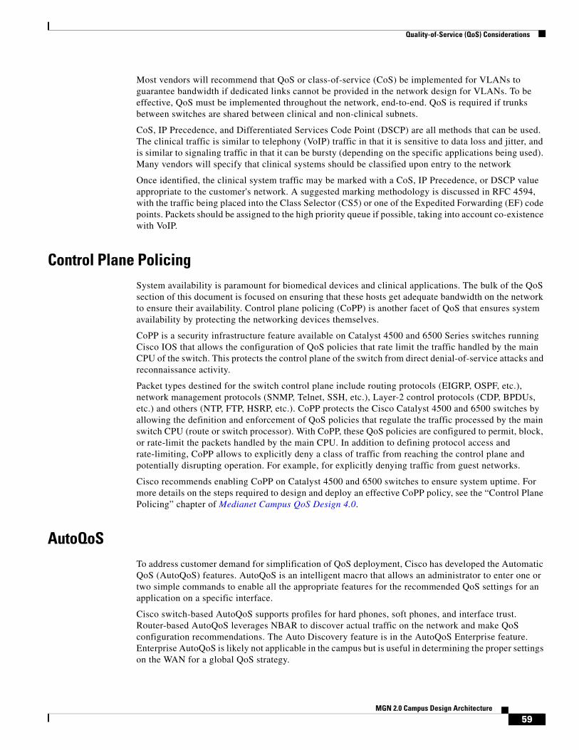
Quality-of-Service (QoS) Considerations
Most vendors will recommend that QoS or class-of-service (CoS) be implemented for VLANs to guarantee bandwidth if dedicated links cannot be provided in the network design for VLANs. To be effective, QoS must be implemented throughout the network, end-to-end. QoS is required if trunks between switches are shared between clinical and non-clinical subnets.
CoS, IP Precedence, and Differentiated Services Code Point (DSCP) are all methods that can be used. The clinical traffic is similar to telephony (VoIP) traffic in that it is sensitive to data loss and jitter, and is similar to signaling traffic in that it can be bursty (depending on the specific applications being used). Many vendors will specify that clinical systems should be classified upon entry to the network
Once identified, the clinical system traffic may be marked with a CoS, IP Precedence, or DSCP value appropriate to the customer's network. A suggested marking methodology is discussed in RFC 4594, with the traffic being placed into the Class Selector (CS5) or one of the Expedited Forwarding (EF) code points. Packets should be assigned to the high priority queue if possible, taking into account co-existence with VoIP.
Control Plane PolicingSystem availability is paramount for biomedical devices and clinical applications. The bulk of the QoS section of this document is focused on ensuring that these hosts get adequate bandwidth on the network to ensure their availability. Control plane policing (CoPP) is another facet of QoS that ensures system availability by protecting the networking devices themselves.
CoPP is a security infrastructure feature available on Catalyst 4500 and 6500 Series switches running Cisco IOS that allows the configuration of QoS policies that rate limit the traffic handled by the main CPU of the switch. This protects the control plane of the switch from direct denial-of-service attacks and reconnaissance activity.
Packet types destined for the switch control plane include routing protocols (EIGRP, OSPF, etc.), network management protocols (SNMP, Telnet, SSH, etc.), Layer-2 control protocols (CDP, BPDUs, etc.) and others (NTP, FTP, HSRP, etc.). CoPP protects the Cisco Catalyst 4500 and 6500 switches by allowing the definition and enforcement of QoS policies that regulate the traffic processed by the main switch CPU (route or switch processor). With CoPP, these QoS policies are configured to permit, block, or rate-limit the packets handled by the main CPU. In addition to defining protocol access and rate-limiting, CoPP allows to explicitly deny a class of traffic from reaching the control plane and potentially disrupting operation. For example, for explicitly denying traffic from guest networks.
Cisco recommends enabling CoPP on Catalyst 4500 and 6500 switches to ensure system uptime. For more details on the steps required to design and deploy an effective CoPP policy, see the “Control Plane Policing” chapter of Medianet Campus QoS Design 4.0.
AutoQoSTo address customer demand for simplification of QoS deployment, Cisco has developed the Automatic QoS (AutoQoS) features. AutoQoS is an intelligent macro that allows an administrator to enter one or two simple commands to enable all the appropriate features for the recommended QoS settings for an application on a specific interface.
Cisco switch-based AutoQoS supports profiles for hard phones, soft phones, and interface trust. Router-based AutoQoS leverages NBAR to discover actual traffic on the network and make QoS configuration recommendations. The Auto Discovery feature is in the AutoQoS Enterprise feature. Enterprise AutoQoS is likely not applicable in the campus but is useful in determining the proper settings on the WAN for a global QoS strategy.
59MGN 2.0 Campus Design Architecture

Quality-of-Service (QoS) Considerations
AutoQoS may be appropriate for the simplest QoS design that involves simply protecting VOIP traffic. To protect medical applications, additional configuration is needed. The AutoQoS templates can serve as a good starting point.
Wireless QoSWireless is a logical extension of the campus network and should be included in the overall campus QoS design. Wireless is becoming increasingly critical to medical facilities as more medical and clinical applications are delivered to the highly mobile staff. Patients, visitor and visiting physicians are bringing more consumer wireless devices into hospitals. While this is the fastest growing area of the network, wireless speeds still lag far behind wired speeds and present the greatest potential bottleneck in the campus.
Wireless presents a unique challenge for QoS enforcement. Unlike wired connections on switches and routers, the radio frequency spectrum is a shared media access where collisions and interference can impact both high priority traffic and low priority traffic. To create a QoS enforcement mechanism, the 802.11e standard committee ratified MAC Enhancements for Quality of Service in July 2005. This mechanism requires clients to properly identify their priority to control access to the transmission channel. Adoption uptake has been slow but some clients have the appropriate controls in place.
The 802.11e standard defines Enhanced Distributed Channel Access (EDCA) to control how clients can transmit traffic at different priorities. The levels of priority in EDCA are called access categories (ACs). Table 2 shows how ACs map directly from Ethernet-level class-of-service (CoS) priority levels. Note how priorities 1 and 2 map into the lowest access category creating a less than best-effort class for wireless.
802.11 wireless uses the Distributed Coordination Function (DCF) to provide Media Access Control (MAC). EDCA provides different levels of priority access by controlling MAC timing. Refer to Table 3 and detects that another client is already transmitting, the Arbitrated Interframe Spacing (AIFS) defines how long it must wait before attempting to transmit again. When multiple clients try to transmit at the same time, they will each select a random amount of time between 0 and their defined contention window to pause before attempting to retransmit. The contention window grows between CWmin and CWmax if there are repeated collisions. Note that high-priority traffic will generally be allowed to transmit sooner than lower priority traffic.
Table 2 Ethernet CoS to Wireless Access Category Mapping
Priority 802.1Q Priority 802.1Q Designation Access Category
Lowest 1 Background (BK) Background (AC_BK)
2 Spare (-) Background (AC_BK)
0 Best Effort (BE) Best Effort (AC_BE)
3 Excellent Effort (EE) Best Effort (AC_BE)
4 Critical Applications (CL) Video (AC_VI)
5 Video (VI) Video (AC_VI)
6 Voice (VO) Voice (AC_VO)
Highest 7 Network Control (NC) Voice (AC_VO)
60MGN 2.0 Campus Design Architecture

Voice and Collaboration Considerations
The Transmit Opportunity (TXOP) parameter shows a second option for MAC. Rather than using the contention-based EDCF, clients can request controlled access. The access point can then grant the client a TXOP window. Few clients are able to do this. For more details on wireless QoS, refer to the following design guides.
• Enterprise Mobility Design Guide, QoS chapter http://www.cisco.com/en/US/docs/solutions/Enterprise/Mobility/emob41dg/ch5_QoS.html
• Voice over Wireless Design Guide http://www.cisco.com/en/US/docs/solutions/Enterprise/Mobility/vowlan/41dg/vowlan41dg-book.html
Voice and Collaboration ConsiderationsWith the growing pressures on healthcare providers to increase efficiency, from the government, insurance companies, and more informed patients, there is a need to transform their environments. Unified communications is a large component to any business transformation by providing more efficient and prompt care of the patients, increasing workflow efficiency, and improving employee satisfaction. There are unique fundamental aspects of an end-to-end UC solution that needs to be addressed when designing an MGN. See Figure 33.
Table 3 Enhanced Distributed Channel Access Parameters
Access Category CWmin CWmax AIFSMax 802.11a/g TXOP
Max 802.11b TXOP
Background (AC_BK) 31 1023 7 0 0
Best Effort (AC_BE) 31 1023 3 0 0
Video (AC_VI) 15 31 2 3.008 ms 6.016 ms
Voice (AC_VO) 7 15 2 1.504 ms 3.264 ms
Legacy DCF 15 1023 2 0 0
61MGN 2.0 Campus Design Architecture

Voice and Collaboration Considerations
Figure 33 Example of Collaboration in Healthcare
PoEThe most fundamental and obvious requirement of UC endpoints is power. With any IPT solution, a clear-cut benefit is the ability for the end devices to receive their power from the access layer switches and simultaneously provide a switched port for computer access. However, this requires the proper access switches, PoE blades, power supplies, power lines (proper magnitude of current and voltage), cooling, etc. From a switching infrastructure perspective, the modular nature of the Cisco 3750, 4500, and 6500 allows a customer to retrofit its environment for the proper PoE support. However, the environmentals may be more complex and costly.
ConnectedHospital
ConnectedHealth
InformationExchanges
ConnectedHealth
Authorities
ConnectedPatient
ConnectedClinician
ConnectedLife Sciencesand Research
ConnectedPublicHealth
ConnectedFunder
or Payer
2294
83
62MGN 2.0 Campus Design Architecture

Voice and Collaboration Considerations
Figure 34 Switching Portfolio
The first step in evaluating the demands of access closets requires determining the number of PoE devices that will be powered during the life of the switch as well as their corresponding class. Healthcare providers are being asked to power more and more devices outside of just class 1, 2, and 3 IP phones. Some examples are 802.11n WLAN APs, physical security devices, and PoE powered thin clients. With the introduction of PoE + (up to 30W per port), the number of PoE devices and overall power draw will continue to increase.
Figure 35 Device Type
A good rule of thumb is to plan to power all needed IPT devices and WLAN APs day one. If there are TDM phones today, plan to power the same number of devices per floor. This is a safe assumption because with the emergence of seamless mobility UC technologies (such as Cisco Mobility 8.0 for the iPhone, MVS 5.0 for the Blackberry, Vocera Badges, and the Cisco 7925), it can safely be assumed that the total number of wired UC devices will decrease over time; however, as stated earlier, new devices like thin client workstations and medical devices will be added, which require PoE. This is simply a rule of thumb. If a large number of PoE powered thin clients are being introduced into the environment alongside color screened Cisco phones and physical security cameras, the maximum draw could be considerably more.
Cisco UC 8.0 SRND – PoE
http://www.cisco.com/en/US/docs/solutions/Verticals/Healthcare/MGN_2.0.html#wp1148277
Cisco Catalyst Switch PoE Support
Once the approximate number of PoE devices that require support for the foreseeable future have been determined, the platform that will be used throughout the environment may be selected. The Cisco 6500 provides the highest PoE device capacity; however, it is very possible that the Cisco 4500 and 3750-x/3560-x will fit the facility’s needs from a power perspective. The platform selection will most likely be made based on MGN needs in regards to resiliency and responsiveness (see“Responsive”
63MGN 2.0 Campus Design Architecture

Voice and Collaboration Considerations
section on page 9 and “Resilient” section on page 9). Refer to the following links for power supply specification that is specific to each platform that might be needed in determining the proper switch for your environment.
• 6500 Relevant Power Documentation
– 6500 Hardware Installation Guide—Power Supply Specs
– Cisco Catalyst 6500 Series Mixed Media Gigabit Ethernet Modules
– Cisco 6500 and 7600 Series 6000W DC Power Supply
– 8700 Watt Enhanced AC Power Supply for Cisco Catalyst 6500 Series Switches
– 6000-WATT AC Power Supply for the Cisco Catalyst 6500 Series Chassis
• 4500 Relevant Power Documentation
– 4500 Hardware Installation Guide—Power Supply Specs
– Cisco Catalyst 4500 Series Power-over-Ethernet Capabilities and Power Supplies
– Cisco Catalyst 4500 Series Line Cards
• 3750-x/3560-x Relevant Power Documentation
– Cisco Catalyst 3750-X and 3560-X Series Switches Data Sheet
Cisco Power Calculator
The Cisco power calculator is an invaluable tool for all information needed on introducing or increasing PoE support on any PoE-capable Cisco Catalyst switch. The main information you will gain from leveraging this tool is understanding how many devices your current switch will support, what you would need in order to increase support, and the corresponding heat dissipation (British thermal unit [Btu] per hour) for environmental considerations. Start with the following informative FAQ (http://tools.cisco.com/cpc/help.jsp) in order to get the most out of the tool.
64MGN 2.0 Campus Design Architecture
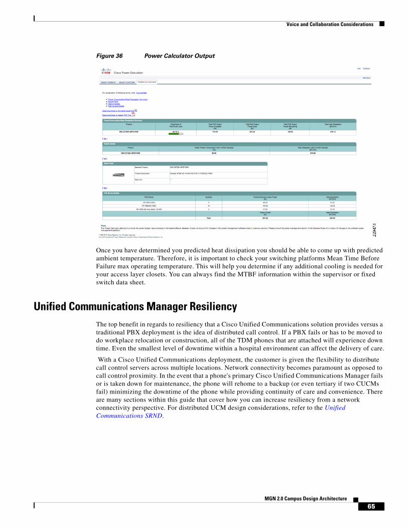
Voice and Collaboration Considerations
Figure 36 Power Calculator Output
Once you have determined you predicted heat dissipation you should be able to come up with predicted ambient temperature. Therefore, it is important to check your switching platforms Mean Time Before Failure max operating temperature. This will help you determine if any additional cooling is needed for your access layer closets. You can always find the MTBF information within the supervisor or fixed switch data sheet.
Unified Communications Manager ResiliencyThe top benefit in regards to resiliency that a Cisco Unified Communications solution provides versus a traditional PBX deployment is the idea of distributed call control. If a PBX fails or has to be moved to do workplace relocation or construction, all of the TDM phones that are attached will experience down time. Even the smallest level of downtime within a hospital environment can affect the delivery of care.
With a Cisco Unified Communications deployment, the customer is given the flexibility to distribute call control servers across multiple locations. Network connectivity becomes paramount as opposed to call control proximity. In the event that a phone's primary Cisco Unified Communications Manager fails or is taken down for maintenance, the phone will rehome to a backup (or even tertiary if two CUCMs fail) minimizing the downtime of the phone while providing continuity of care and convenience. There are many sections within this guide that cover how you can increase resiliency from a network connectivity perspective. For distributed UCM design considerations, refer to the Unified Communications SRND.
65MGN 2.0 Campus Design Architecture

Voice and Collaboration Considerations
Healthcare VoWLAN ConsiderationsHealthcare by its nature is both collaborative and mobile, with caregivers moving from patient-to-patient and room-to-room. Voice over Wireless LAN communications devices can dramatically improve caregivers’ productivity by making them instantly available for consultation. This productivity can be further enhanced by integrating applications like Nurse Call. With Nurse Call integration, when a patient pushes the Nurse Call button, a message is sent to the VoWLAN device associated with the nurse responsible for the room where the button was pushed. With the push of a single softkey, the nurse can establish a call with the patient, and determine the nature of the request rather than having to drop what he or she is doing to go to the patient’s room to determine what the patient needs. Since this and other applications improve caregiver productivity and patient safety, they become critical tools in patient care; therefore, consideration should be taken to ensure their availability and reliability.
Since WLAN leverages a shared, half duplex medium, certain precautions need to be taken. This is especially true when dealing with voice given that it is based on UDP and, in turn, extremely sensitive to packet loss. For example, while surfing the web, if you pick up your open laptop, walk down the hallway and start surfing again from another access point, you really would not notice if you happened to lose a couple of packets due to roaming issues. However, if you take the same walk while continuing to view a youtube video, you will notice lost frames or audio if roaming is not handled correctly. Within Healthcare, if a nurse was to walk from one patient room to another while continuing a Vocera voice call with a doctor, packet drops could mean the interruption of a conversation that may be important for high quality patient care. Below are some considerations that should be made when designing and configuring a Medical Grade WLAN that will support VoWLAN applications.
Site Surveys
While site surveys are important in any WLAN deployment, in the healthcare environment with different building types, shielded rooms, and large, dense pieces of equipment that may be mobile, along with the critical nature of the facility, site surveys are critical. Before any type of site survey, equipment procurement or configuration can take place, you first need to determine the devices that your WLAN will support. This will be important in determining the spectrums you can leverage (2.4Ghz r 5Ghz) and the max power your APs will be able support. Within healthcare, one of the most popular VoWLAN devices is the Vocera B1000 and B2000 badges. However, it is also one of the more difficult devices to support within a healthcare environment, given its weak radio and lack of support for CCX v4 and 802.11a support. This combination of shortcomings can lead to a large amount of packet loss which will make them virtually unusable within a hospital environment. For details on how you can limit these issues within your environment, refer to the Cisco Vocera Deployment Guide.
66MGN 2.0 Campus Design Architecture

Voice and Collaboration Considerations
Figure 37 Vocera B100 Picture
When designing the wireless network, take into account the radio capabilities of asset scanners and WiFi-capable cellular devices. Given the mobile nature of doctors within hospital environments as well as between different care facilities, there has been a large amount of interest in the iPhone Cisco Mobile 8.0 and Black Berry MVS 5.0 products. These solutions allow end users to attach to the Unified Communications Manager over the WLAN, cutting costly cellular minutes and providing a seamless end user experience with desktop IPT. The number of these devices using the wireless network will grow dramatically over the next few years.
Once you have determined the types of devices that will be leveraged for VoWLAN within your environment, refer to the Cisco VoWLAN Design Guide for recommendations about the site survey.
Non-802.11 Device Interference
Hospital environments have been found to be one of the noisiest environments when it comes to non-802.11 device interference. Sources of this interference can be anything from microwaves to 2.4 Ghz headsets and even physical security cameras. Couple this large amount of interference with the sensitivity of the VoWLAN traffic and you quickly understand the need for a spectrum analyses tool to help you identify and mitigate sources of interference.
With the release of Wireless LAN Controller 7.0, Cisco announced the 3500 AP that has integrated support for spectrum analysis. This means that you have a constant view into the quality of the air within your environment without deploying separate probes. Not to mention, the Cisco Unified WLAN Solution will be able to dynamically adjust transmit power and channel for each AP’s given more visibility into the spectrum. For more information, refer to 3500 landing page on Cisco.com.
67MGN 2.0 Campus Design Architecture

Voice and Collaboration Considerations
Figure 38 Clean Air Diagram
VoWLAN QoSAny traffic that is critical to patient care and sensitive to delay needs to be prioritized in order to limit any possible affects of congestion. An end-to-end QoS policy is paramount for not only WLAN, but also your LAN, WAN, and DC. In order to confirm that you are leveraging all QoS mechanisms within your WLAN solution to match your corporate QoS policy, consult the Cisco End-to-End WLAN QoS Guide.
Figure 39 End-to-End Diagram
For more information on WMM or over the air prioritization, refer to the WMM Configuration Guide at the following URL:
http://www.cisco.com/en/US/docs/wireless/controller/5.2/configuration/guide/c52wlan.html#wp1314167
Detect and Classify Locate Mitigate
Understand where inyour facility interferenceis an issue
CleanAir Radio ASIC –Hardware based visibility
Avoid interference with network intelligence
2294
75CH 1
Maintain Air Quality
Poor Good
CH 11
Voice Client(Platinum QoS Profile)
Voice Client
FTP Server
Video Client
Video Client(Gold QoS Profile)
FTP Client(Bronze QoS Profile)
WLC
Router 2Router 1
Voice, Video and FTP packetsclassified and marked at F3/0
WRED Implemented onS2/0 and S0/0
F0/0S0/0
S2/0F3/0
LAP
2294
76
IP
LWAPP
68MGN 2.0 Campus Design Architecture
Voice and Collaboration Considerations
Cisco Compatible Extensions
In the next couple of sections, are features that are only supported by endpoints that are compliant with a certain level of Cisco Compatible Extensions (CCX). The CCX program ensures the widespread availability of client devices that are interoperable with a Cisco WLAN infrastructure and take advantage of Cisco innovations for enhanced security, mobility, quality of service, and network management. Cisco Compatible client devices are sold and supported by their manufacturers, not Cisco. For details on Cisco Compatible products, refer to the product list. For a complete list of versions and supported features, see the following link.
Figure 40 CCX Logo
Call Admission Control
If the end client supports CCX v4 or later, they may be able to leverage the Dynamic Call Admission Control feature with the Cisco Unified WLAN solution. This feature allows a VoWLAN endpoint to make an informed decision on which AP to associate to in order to avoid predictable quality issues. For additional details, refer to page 24 of the Cisco Unified Wireless IP Phone 7925G Deployment Guide.
VoWLAN TroubleshootingOne of the main causes of quality issues for endpoints within a healthcare environment is the lack of education of the end user on where they may or may not be able to use the device. When a nurse or doctor gets a new device they may assume that they can use it wherever a cell phone may be used. For example, the cafeteria, court yard, home, across the street at Starbucks, etc. Not only will this lack of education guarantee their dissatisfaction with the quality of the application, but it will also make it virtually impossible to troubleshoot issues. If you cannot pin point which APs the user was associated to during the issues, it will be very difficult to fix.
One feature that allows more visibility into the quality of voice conversations per AP is the traffic stream metrics feature. Since packet latency and packet loss is reported per AP and device, an administrator can easily isolate poor voice quality issues. For more information, refer to the following URL:
http://www.cisco.com/en/US/docs/wireless/controller/5.2/configuration/guide/c52ccfg.html#wp1095515
MulticastThere are many different UC applications that require multicast on your network and WLAN. The most popular within healthcare is the Vocera one to many broadcast feature. In order to support this feature, multicast must be enabled on the WLAN infrastructure. There are two options for multicast on Cisco Unified WLAN solution: unicast/multicast and multicast. Unicast/multicast does not require that multicast be enabled between the controller and APs. However, this protocol does not scale as well as
2294
77
69MGN 2.0 Campus Design Architecture

Voice and Collaboration Considerations
the multicast option. With the multicast option, multicast packets are dropped outside of LWAPP onto the LAN for delivery. Make sure to take this into consideration when deploying multicast on your infrastructure.
• Campus Design Guide—Multicast
http://www.cisco.com/en/US/docs/solutions/Enterprise/Campus/campover.html
• Vocera or VoWLAN Design Guide—Multicast
http://www.cisco.com/en/US/docs/solutions/Enterprise/Mobility/vowlan/41dg/vowlan41dg-book.html
Figure 41 Unicast Multicast vs Multicast/Multicast Diagram
SecurityIn general, voice and patient-critical traffics are only as reliable as they are secure. Targeted denial-of-service attacks on voice subnets can greatly affect overall quality and availability. MGN security as a whole was covered in the MGN 2.0 Security whitepaper. For the section covering communication devices, refer to the following URL:
http://www.cisco.com/en/US/docs/solutions/Verticals/Healthcare/MGN_2.0.html#wp1148277
2294
78
LWAPP
LWAPP
LWAPPLWAPP Tunnels
Unicast Mechanism
Three LWAPP unicastpackets out
One multicast packet in
LWAPP
LWAPP
LWAPP
LWAPPMulticast Group
Multicast Mechanism
One LWAPP multicastpacket out
Network replicatespacket as needed
One multicast packet in
70MGN 2.0 Campus Design Architecture

Voice and Collaboration Considerations
Figure 42 Voice Security Overview
Unified Secure Voice MessagingHealthcare environments maintain strict security policies due to the heavily enforced requirements set by PCI and HIPPA in order to protect patient information. Some providers find it important to encrypt voice messages within a unified E-mail and voicemail configuration. This feature can protect against malicious or accidental delivery of sensitive patient information to the wrong destinations. Cisco Unity unified messaging can encrypt messages as they are taken. You can then listen to the messages either through the telephone user interface (TUI) or from Microsoft Outlook, and the messages will be properly decrypted. With Secure Messaging, if a message is then forwarded outside the organization, the recipient of the forward will be unable to decrypt that message. Secure Messaging may be used to prevent messages from leaving the organization.
Additionally, messages may be marked as private, in which case the encryption mechanism limits playback to only the original intended recipient. Encryption keys may be configured to expire after a set period of time, so messages will become unplayable records after the end of the expiry period even if copied to a computer hard drive. With Secure Messaging security and compliance policies will be strictly adhered to while still allowing users the benefits of unified messaging. For more information, refer to the following URL:
http://www.cisco.com/en/US/partner/prod/collateral/voicesw/ps6789/ps5745/ps2237/data_sheet_c78-582651.html
With all security features it is always a give a take between security and the effects on end user experience. Although there is a road map for Unity Connection OWA and MAC secure messaging support, it is not currently supported on Unity Connection 8.0. If you have users within your environment
SiSi
IntranetInternet
IP IP IP IP
M
M
LWAPPLWAPP
Applications• Multilevel administration• Toll fraud protection• Secure Management• Hardended Platforms
Call Management• Hardened Windows OS• Digital certificates• Signed softward images• Integrated Host Intrusion
Prevention• H323 MGCP SCCP SIP
Infrastructure• VLAN segmentation• Layer 2 protection• Firewall• Intrusion detection• QoS and thresholds• Secure VPN• Wireless security
Endpoints• Digital certificates• Authenticated phones• GARP protection• TLS protected signaling• SRTP media encryption• Centralized management
2287
06
71MGN 2.0 Campus Design Architecture

Voice and Collaboration Considerations
that access E-mail through OWA or a MAC client, they must be educated to use the TUI in order to listen to voice mails they see within their inbox. Also, with Connection 8.0, you can configure Unified Messaging only for your Microsoft outlook users.
For additional information about Unity Connection security and overall reliability, see the UCM 8.0 SRND at the following URL:
http://www.cisco.com/en/US/docs/voice_ip_comm/cucm/srnd/8x/vmessage.html
For secure messaging configuration, refer to the following URL:
http://www.cisco.com/en/US/partner/docs/voice_ip_comm/connection/8x/roadmap/8xcucdg.html
For CxN Data Sheet, refer to the following URL:
http://www.cisco.com/en/US/partner/prod/collateral/voicesw/ps6789/ps5745/ps2237/data_sheet_c78-582651.html
Session Manager Edition
The adoption of IPT has been slower within HC due to previous HA concerns. Now due to the realization of the resiliency and agility benefits of a distributed IPT solution over a fixed TDM, an increasing number of healthcare providers are starting to switch to Cisco UC taking advantage of the healthcare application integration advantages. Although this migration creates important business relevant solutions for the hospital, it creates two unique considerations for IT: supporting multiple UCM clusters due to third-party integration code dependencies and PBX integration and migration. Common third-party integrations are Nurse Connect and Emergin secondary alarm notification.
Cisco Unified Communications Manager Session Management Edition is a version of Cisco Unified Communications Manager that provides centralized trunking, application, and policy control. It reduces communication tolls, cuts administrative overhead, and supports easier migration to a full IP telephony environment. In the situation where there is a need to support multiple UCM clusters and multiple PBXs, the session manager edition can increase resiliency and simplify management by housing a unified dial plan. The Session Manager Edition can handle multiple PBX integration protocols such as QSIG and SIP, simultaneously in case your PBXs have different capabilities.
Unified Communications EndpointsWithin the healthcare environment, there is never one size fits all endpoint solution. Depending on the type of user and even individual department requirements, there may be a need for several different types of endpoints within the environment. A few potential use cases are as follows:
• Public Area Telephone—Wall-mounted phones in heavily trafficked areas.
• Exam Room Telephone—Phones with two-way speaker capabilities for use within diagnostic areas.
• Nurse Station Telephone—Supports all features need for central nurse stations that will support all third-party HC integrations.
• Administrative Telephone—Phones featuring a large number of additional lines used by administrators, secretaries and receptionists.
• Executive or Physician Telephone—Phones that meet the requirements of physicians and executives.
• Audio Conferencing Unit for Medium and Large Conference Rooms
• Wireless 802.11 Phone
72MGN 2.0 Campus Design Architecture

Voice and Collaboration Considerations
Once you have determined the requirements according to end user or area, you can use the “Unified Communications End Points” section of the Cisco UC 8.0 SRND to determine which phones will meet the specific needs. For details, refer to the following URL:
http://www.cisco.com/en/US/docs/voice_ip_comm/cucm/srnd/8x/endpnts.html
Figure 43 Cisco Endpoint Portfolio
Remote SurvivabilityWhen determining the features needed according to end user or area of the hospital, make sure to take note of which features are required for patient care and safety. This will help determine which remote survivability solution to use in case that connectivity to a UCM subscriber is lost. There are two options: SRST and CME. CME supports more features during outages because it is built off of Communications Manager Express; however, SRST is less processor intensive and scales better for larger sites that do not house a subscriber.
For additional details on SRST vs CME, refer to the SRST Fallback section within the Cisco UC 8.0 Administration Guide at the following URL:.
http://www.cisco.com/en/US/docs/voice_ip_comm/cucme/admin/configuration/guide/cmesrst.html#wp1023679
ISROne of the advantages of Cisco solutions is their ability to scale across technologies. The ISR G2s are no exception, especially when it comes to voice services, due to their support for QoS, QSIG, and SIP integration (between PBX’s and UCM and Unity), CUBE support for SIP Trunking, SRST and PSTN/encoding support.
73MGN 2.0 Campus Design Architecture
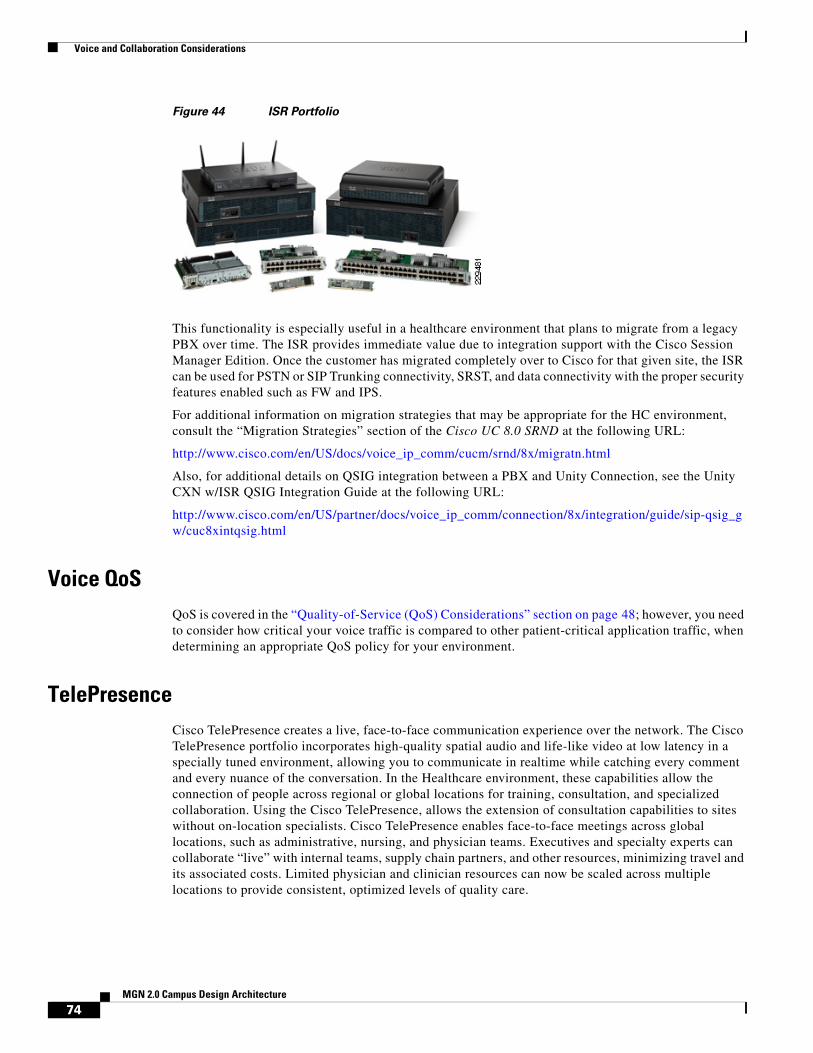
Voice and Collaboration Considerations
Figure 44 ISR Portfolio
This functionality is especially useful in a healthcare environment that plans to migrate from a legacy PBX over time. The ISR provides immediate value due to integration support with the Cisco Session Manager Edition. Once the customer has migrated completely over to Cisco for that given site, the ISR can be used for PSTN or SIP Trunking connectivity, SRST, and data connectivity with the proper security features enabled such as FW and IPS.
For additional information on migration strategies that may be appropriate for the HC environment, consult the “Migration Strategies” section of the Cisco UC 8.0 SRND at the following URL:
http://www.cisco.com/en/US/docs/voice_ip_comm/cucm/srnd/8x/migratn.html
Also, for additional details on QSIG integration between a PBX and Unity Connection, see the Unity CXN w/ISR QSIG Integration Guide at the following URL:
http://www.cisco.com/en/US/partner/docs/voice_ip_comm/connection/8x/integration/guide/sip-qsig_gw/cuc8xintqsig.html
Voice QoSQoS is covered in the “Quality-of-Service (QoS) Considerations” section on page 48; however, you need to consider how critical your voice traffic is compared to other patient-critical application traffic, when determining an appropriate QoS policy for your environment.
TelePresenceCisco TelePresence creates a live, face-to-face communication experience over the network. The Cisco TelePresence portfolio incorporates high-quality spatial audio and life-like video at low latency in a specially tuned environment, allowing you to communicate in realtime while catching every comment and every nuance of the conversation. In the Healthcare environment, these capabilities allow the connection of people across regional or global locations for training, consultation, and specialized collaboration. Using the Cisco TelePresence, allows the extension of consultation capabilities to sites without on-location specialists. Cisco TelePresence enables face-to-face meetings across global locations, such as administrative, nursing, and physician teams. Executives and specialty experts can collaborate “live” with internal teams, supply chain partners, and other resources, minimizing travel and its associated costs. Limited physician and clinician resources can now be scaled across multiple locations to provide consistent, optimized levels of quality care.
74MGN 2.0 Campus Design Architecture

Change Management
Within the campus environment, the primary TelePresence concerns are sufficient bandwidth and QoS (see “Quality-of-Service (QoS) Considerations” section on page 48). Details of TelePresence in Healthcare will be covered in future MGN modules. For information on deploying TelePresence over a converged network infrastructure, refer to the Cisco TelePresence Network Systems 2.0 Design Guide at the following URL:
http://www.cisco.com/en/US/docs/solutions/Enterprise/Video/TP-Book.html
HealthPresenceThe Cisco HealthPresence solution combines Cisco TelePresence, Cisco® Vitals Software, Cisco Session Management Application, and medical devices from third-party vendors that gather and transmit physiological data.
• Cisco TelePresence enables a realistic face-to-face experience, leading the local and remote participants to feel as if they are there in-person.
• Cisco Vitals Software is used for session management data, transmission of medical data, and to help view electronic healthcare information. It manages the session between the patient and the doctor, allowing the data, video, and audio from the medical devices to be intelligently routed across the network. Healthcare providers can see the data immediately and can view a patient's history in tandem with instrument readings.
• Cisco Session Management Application provides interoperability with Cisco Unified Communications, with intelligent routing and management. The system supports one-touch dialing and, because it uses Microsoft Outlook calendar for scheduling, is easy for most people to operate.
• The integrated medical devices include a high-resolution general-examination camera, a telephonic stethoscope, an ear/nose/throat (ENT) scope, and a vital signs monitor for blood pressure, temperature, pulse rate, and pulse oximetry. Together, these devices generate data that help the healthcare provider examine the patient.
While the on-time delivery of video for TelePresence is important, the addition of a high-resolution examination camera, and especially the telemetry from the other medical devices, make QoS and the on-time, loss-free delivery of data highly critical. Lost or delayed data could potentially affect the quality of a patient consultation. QoS is discussed in “Quality-of-Service (QoS) Considerations” section on page 48. Details of HealthPresence in Healthcare will be covered in future MGN modules.
Change ManagementOne constant that exists in a healthcare network is change1. The MGN 2.0 Campus Architecture is an interconnected set of subsystems that rely on each other to function. Clinicians, patients, administrators, suppliers, and IT professional all rely on this system to function and require well documented, planned, and systematic processes when changes are required. A good change management program decreases risk, improves availability, and delivers metrics for the business to continually improve. The section discusses some definitions, best practices, tools and requirements for effectively managing changes in a MGN Campus network.
First, we need a to understand that all of the networked technologies we have discussed up to this point in this document are designed to support business applications and the end users that provide input or receive output from these systems. The network and all the communication services that it interconnects,
1. As previously mentioned, changes involving regulated medical devices may involve regulatory considerations. When planning changes where such implications may be involved, the applicable regulatory obligations, if any, should be understood and acted upon before deploying any such change.
75MGN 2.0 Campus Design Architecture

Change Management
are components of the infrastructure supporting the healthcare provider’s business. To communicate change to the business, the concepts of Services Transition, Service Operation, Release Management and Change Management are key best practices based on the Information Technology Infrastructure Library (ITIL) framework. ITIL's Service Management Lifecycle illustrates the circular relationship between strategy, design, transition, operations and continuous-improvement. These services are key areas to understand when designing a change management system:
• Service Transition focuses on planning for implementation, implementing, documenting, testing, and measuring the effectiveness of the implementation. Change and Release management are processes within this area of the lifecycle.
• Service Operation focuses on what is required to run the system on a daily basis. This includes the operation procedures and processes, incident and problem management techniques, and escalation levels when things cease normal operation.
Change Management creates a structured framework for changes to be made in a consistent, less risky manner. For each change, steps should be taken to identify what is involved, document the “as-is” and “to-be” states, assess the impact with considerations for blackout plans, determine who should authorize the change, create an execution plan, and create an evaluation plan so that everyone knows what a successful change is and when it is complete. Change Management considers each change separately and runs through the series of steps listed above to product consistent results.
Release Management is the orchestrator of changes across the infrastructure. Release Management focuses on the strategic relationship between systems involved, the timing and order of the changes, and tries to deliver a harmonious plan so that downtime is decreased, and consumers of the network services are impacted less by the change.
A successful Change Management system has a solid, prioritized list of both business and technical requirements. It understands the complexities when balancing development and operational requirements. Some always want more bandwidth, faster servers, higher quality video, or faster response time, while others want nonstop production and zero downtime. Nearly every change within the IT department follows a standard Change Lifecycle system similar to the model shown in Figure 45.
Figure 45 Change Lifecycle
Remember that changes are often subcomponents of larger release packages that consist of managed changes. An example of this might be moving to a new version of Cisco Access Control System (CS-ACS). Nearly every device in the MGN relies on the centralized authentication and access control services of CS-ACS. In addition, many software clients, directory servers, and other applications might rely on the central access control policies that CS-ACS enforces across the campus. The same could be said when making changes to a Cisco Unified Communication Management cluster, a Wireless Controller or other key elements in the infrastructure. This is where release management, and the concept of a release package are critical. A release package consists of the following:
• Upper layer components associated with the overall release:
– The release policy
– The release (package) plan
– Portfolio management considerations
2295
17
Request aChange
DocumentRequest for
Change (RFC)
Evaluate
RFC
Change Life Cycle
ScheduleChange
ImplementChange
ReviewChange
76MGN 2.0 Campus Design Architecture

Change Management
• Lower layer components associated with each release:
– Plan
– Define
– Build
– Test
– Deploy
Release management provides the linkage between infrastructure change requests and business application requirements.
Many books and white papers have been written that document best practices in these areas. For Cisco's Change Management best practices, refer to the Change Management Whitepaper at the following URL:
http://www.cisco.com/en/US/partner/technologies/collateral/tk869/tk769/white_paper_c11-458050.html
Now that we have a high-level understanding of what change management is and why it is critical to the success of a Medical Grade Network, we next discuss elements of the MGN Campus Architecture that are used to manage and monitor the infrastructure. The following sections are split into the following functional areas:
• Management Control Plane
• Out-of-Band Management Techniques
• Authentication and Access Control
• Rapid Fault-Isolation Techniques
This section evaluates the consistent process of successfully managing change; the process of planning for, coordinating and validating changes of varying risk levels. The intent is not to perform an exhaustive evaluation of the change management process but to determine if a change management process is in place and if it is adhered to by the organization. In addition, an evaluation will be made based off of the interviews to determine if change is a leading contributor to outages in the organization.
Change management procedure is recommended for all network changes. This requires change procedure documentation and organization wide acceptance. Management must continually reinforce the importance of these change management procedures to all individuals involved with network change.
Overall, change planning and validation is more successful if change management procedures are followed and the organization increases planning and validation requirements based on initial risk assessment. If your organization does not have a change management practice in place, you may want to refer to the following as a guideline:
http://www.cisco.com/en/US/technologies/collateral/tk869/tk769/white_paper_c11-458050.html
Management Control PlaneEach system in the MGN has a management control plane and a data plane. The management control plane is used to manage and monitor devices, access configuration data, collect operational statistics, and perform software updates. The data plane is the part of the infrastructure device where actual data travels across access media (i.e., cables, WLAN airwaves) into the port and through the interior packet pathways. The devices in the MGN architecture have both an in-band management interface (e.g. loopback addresses, virtual terminal ports) and out-of-band management interfaces (dedicated console ports, dedicated Cisco IOS physical, or logical interfaces that process management traffic only).
77MGN 2.0 Campus Design Architecture

Change Management
Because of the critical services running on an MGN, extra care must be designed into the system to ensure that the management plane is not compromised. Regulatory compliance requirements, including HIPAA and PCI compliance, require that the management plane is secured with strong passwords, role-based centralized access control, and encrypted protocols for remote management of in-scope infrastructure equipment.
Out-of-Band Management TechniquesBecause the defense of the management plane is of critical importance to the MGN, out-of-band management is commonly used to create a more secure separation between private healthcare or payment related traffic and the operational traffic used to manage and monitor the infrastructure. By contrast, in-band management is the use of regular data channels to manage devices (i.e. through the Ethernet interface). A significant limitation of the in-band management is its vulnerability to problems from the very devices that are being managed.
Different techniques have been used over the years to remotely manage the infrastructure in the event that data plane was compromised. Figure 46 illustrates a remote administrator using a combination of 3G cellular interfaces to create an out-of-band, SSH terminal access connection to console into a Cisco router acting as a remote terminal server with physical console port cable access to the remote equipment.
Figure 46 Out-of-Band Management
The Cisco SAFE Reference Guide uses the model in Figure 47 to illustrate the differences between in-band and out-of-band management systems and recommended a dedicated management module for improved secure access control to the management systems.
2295
18
3- SSH on 22008
2- DYN-ACL
C-2509
1- SSH on 22008
C-1841 (HWIC-3G-GSM)
78MGN 2.0 Campus Design Architecture

Change Management
Figure 47 In-Band vs Out-of-Band Management Systems
For details, refer to the Cisco SAFE Reference Guide at the following URL:
http://www.cisco.com/en/US/docs/solutions/Enterprise/Security/SAFE_RG/chap9.html
Out-of-band management is also commonly used for remote or centralized server management. Legacy servers may still have a modem connected to an analog phone line or remote access server for remote dial-in administration. Newer servers have built-in remote access systems (ILOM, DRAC, HILO, IPMT) and remote keyboard, video and mouse (KVM) interfaces. Avocent, (now part of Emerson Corporation), which was formed by the merger of the two largest KVM manufacturers, Apex and Cybex, offers the largest selection of out-of-band management products.
Careful planning is important when designing the management of the MGN Campus infrastructure. This should take into consideration local IT staffing levels, service level agreements (SLAs) with clinical and administrative stakeholders, power backup capabilities, service provider network infrastructure and SLAs, and overall network management capabilities.
WAN
CoreSwitches
2267
03
Out-of-Band Management
In-Band Management
WANEdge
Routers
WANDistributionSwitches
Firewalls
Branch
CampusDevices
Data CenterDevices
AdminVPN
M
ConsoleServer
ConsoleConnectors
NTPServer
CS-MARSCS-ACS
ConsoleServer
ConsoleConnectors
CSM NACManager
AdminHost
79MGN 2.0 Campus Design Architecture

Change Management
Authentication and Access ControlWho, when, where and how a group of individual is allowed to use the services on the MGN Campus are another set of important considerations in designing a MGN Campus. Cisco's Network Access Control and the BioMedical Network Access Control solutions were discussed earlier in this document, and offer important components in a comprehensive access control design.
At the network infrastructure level, Authentication, Authorization and Authorization (AAA) protocol, is widely used by network infrastructure equipment as part of the access control system. Role-based access control, which has been the norm for many years is evolving into identity-based access control. As more services in the network converge, modern healthcare companies design multiple layers of authentication and access control that goes beyond the network protocols.
In many cases, physical access control systems are integrated with the network linking IP video surveillance, door lock controllers, badge or biomedical readers, and alarm controllers into a Smart+Connected access control system. Figure 48 and Figure 49 depict these intelligent physical security and network access control systems.
80MGN 2.0 Campus Design Architecture

Change Management
Figure 48 Example of Physical Security System
Rugged/OutdoorMobile
2292
00
Analog andIP Cameras
Rugged ISR
IP Phone
OM ClientOM Client VHF
IP
Analog andIP Cameras
Cisco IPCameras
StorageSystem
IP
IP IP
Analog Cameras
Rugged ISR, VMSS
OutdoorMesh
Branch
Incident Response
Access ControlVideo Surveillance
Hybrid
Campus
ISR, MS,AVG,VMSS
IP
CiscoRouters
IPGateway
CiscoRouters
CiscoRouters
ISR
OM ClientPhysicalAccess
Gateway
PhysicalAccess
Manager
PhysicalAccessClient
IPICS Client
SM Client
CCTV Monitorsand Joysticks
IP
IPICS Server
VirtualMatrixSwitching
Back Office
Media Server, OperationsManager, Virtual Matrix
IP Network
Encoder
Video Wall
Custom Interface
Video Analytics
81MGN 2.0 Campus Design Architecture

Rapid Fault-Isolation Techniques
Figure 49 Example of Network Access Control System
Rapid Fault-Isolation TechniquesIn the healthcare environment, the network delivers critical tools to caregivers that may affect the delivery of care, so it is essential that the network is always available and any faults are isolated in the minimum possible time. This section discusses some tools and techniques used to minimize network down time.
NTP Sync—PTP 1588 Time StampingInternet Protocol (IP)-based networks have evolved from the traditional best effort delivery model to a model where performance and reliability need to be quantified and, in many cases, guaranteed with Service Level Agreements (SLAs). The need for greater insight into network characteristics has led to significant research efforts being targeted at defining metrics and measurement capabilities to characterize network behavior. The foundation of many metric methodologies is the measurement of time.
In the healthcare environment, compliance is a big issue. Several regulations that apply to healthcare (including HIPAA and PCI) require the ability to accurately time stamp data and transactions. HIPAA explicitly calls out accurate time stamps as a contributing factor for appropriate access controls. The best way to insure accurate time stamps is NTP.
Network time synchronization is a critical component of IP networks. Depending on the business models, and the services being provided, the characterization of network performance can be considered an important competitive service differentiator. In many cases, great expense may be incurred deploying network management systems and directing engineering resources towards analyzing the collected performance data. However, if proper attention is not given to the often-overlooked principle of time synchronization, those efforts may be rendered useless.
Video and DeviceCapture
Video Surveillance, Access Controland Incident Management
Response
2276
77
IP SurveillanceCameras
Radios, Mobile Phones,IP Phones
Digital Signage
Desktop
Cisco VideoSurveillanceOperations
Manager (VSOM)
Safety andSecurity
Third PartyAnalog and IP
Cameras
IP
Physical AccessManager Multiservices
Platform
Physical AccessGateway
IP
IPICSMultiservices
Platform
ISR - Video MediaManagement and
Storage
Open API - ThirdParty Systems
IP
82MGN 2.0 Campus Design Architecture

Rapid Fault-Isolation Techniques
Network Time Protocol (NTP) synchronizes timekeeping among a set of distributed time servers and clients. This synchronization allows events to be correlated when system logs are created and other time-specific events occur.
Precision Timing Protocol (PTP) provides for accurate time synchronization over packet-switched networks. PTP is designed for systems requiring very high accuracies beyond those attainable using NTP (typically in the sub-microsecond range).
First Failure Analysis—Syslog, SNMP, NetFlow, XMLThe following features are valuable monitoring tools that, when implemented properly, can proactively capture persistent issues affecting a network. There are instances where one or more of these features may display events that the others do not see. It is for this reason that it is recommended to implement them in a layered approach.
Syslog is a method to collect messages from devices to a server running a syslog daemon. Logging to a central syslog server helps in aggregation of logs and alerts. A syslog service simply accepts messages, and stores them in files or prints them according to a simple configuration file. This form of logging is the best available for Cisco devices because it can provide protected long-term storage for logs. This is useful both in routine troubleshooting and in incident handling. Syslog is used by healthcare information systems. For example, access to identifiable patient information must be logged. Technical frameworks to insure HIT system interoperability are defined by the Integrating the Healthcare Enterprise (IHE).
http://www.ihe.net/
The method recommended in the Audit Trail and Node Authentication (ATNA) integration profile in IHE is syslog.
Simple Network Management Protocol (SNMP) is a UDP-based network protocol. It is used mostly in network management systems to monitor network-attached devices for conditions that warrant administrative attention. It consists of a set of standards for network management, including an application layer protocol, a database schema, and a set of data objects. SNMP exposes management data in the form of variables on the managed systems, which describe the system configuration. These variables can then be queried (and sometimes set) by managing applications.
Cisco IOS NetFlow and IOS Flexible NetFlow efficiently provides a key set of services for IP applications, including network traffic accounting, usage-based network billing, network planning, security, denial-of-service monitoring capabilities, and network monitoring. NetFlow provides valuable information about network users and applications, peak usage times, and traffic routing. The basic output of NetFlow is a flow record. Several different formats for flow records have evolved as NetFlow has matured. The most recent evolution of the NetFlow flow-record format is known as NetFlow version 9. The distinguishing feature of the NetFlow Version 9 format, which is the basis for an IETF standard, is that it is template-based. Templates provide an extensible design to the record format, a feature that should allow future enhancements to NetFlow services without requiring concurrent changes to the basic flow-record format. In addition, Cisco IOS Flexible NetFlow is the next-generation in flow technology allowing optimization of the network infrastructure, reducing operation costs, improving capacity planning and security incident detection with increased flexibility and scalability. Using templates provides several key benefits:
• New features can be added to NetFlow more quickly, without breaking current implementations.
– NetFlow is “future-proofed” against new or developing protocols, because the NetFlow version 9 format can be adapted to provide support for them.
83MGN 2.0 Campus Design Architecture

Rapid Fault-Isolation Techniques
– NetFlow version 9 is the IETF standard mechanism for information export.
Third-party business partners who produce applications that provide collector or display services for NetFlow will not be required to recompile their applications each time a new NetFlow feature is added; instead, they may be able to use an external data file that documents the known template formats. For more information about NetFlow, refer to the following URLs:
http://www.cisco.com/en/US/products/ps6601/products_ios_protocol_group_home.html
http://www.cisco.com/go/fnf
• XML management interface can be used to configure devices. The interface uses the XML-based Network Configuration Protocol (NETCONF) that allows you to manage devices and communicate over the interface with an XML management tool or a program. NETCONF is implemented with an XML Schema (XSD) that allows you to enclose device configuration elements within a remote procedure call (RPC) message. From within an RPC message, you select one of the NETCONF operations that match the type of command that you want the device to execute. You can configure the entire set of CLI commands on the device with NETCONF.
Cisco.com ToolsThe following tools can be located on Cisco.com under support then tools and resources.
Cisco Notification Service
The Cisco Notification Service allows you to create customized flexible notification alerts that can be sent via E-mail or RSS feed, on critical product support subjects: Security Advisories, Field Notices, End of Sale/Support statements, Software Updates, and Known Bugs. The Cisco Notification Service offers the ability to set up one or more profiles that will enable you to receive notifications on the Topic-Subtopic you choose, and allows you to group Cisco information into common notifications.
TAC Case Collection
The TAC Case Collection helps you interactively identify and troubleshoot common problems involving hardware, configuration, and performance issues. These solutions, provided directly by TAC engineers, have resolved actual networking problems.
Output Interpreter
The Output Interpreter is a troubleshooting tool that reports potential problems by analyzing supported show command output. The Output Interpreter supports various show command output from Cisco routers, switches, PIX/ASA firewalls, IOS wireless access points, or Meeting Place Platforms. The Output Interpreter continues to support new features. Some of the new features include support for GOLD diagnostics and other outputs:
• Cisco 12000 IOS XR firmware, hardware, and software readiness assessment (up to version 3.8)
• Wireless LAN Controller—show and debug commands
• GOLD diagnostics—show diagnostic result command
• ASA Commands—show tech-support and show running-config commands
84MGN 2.0 Campus Design Architecture
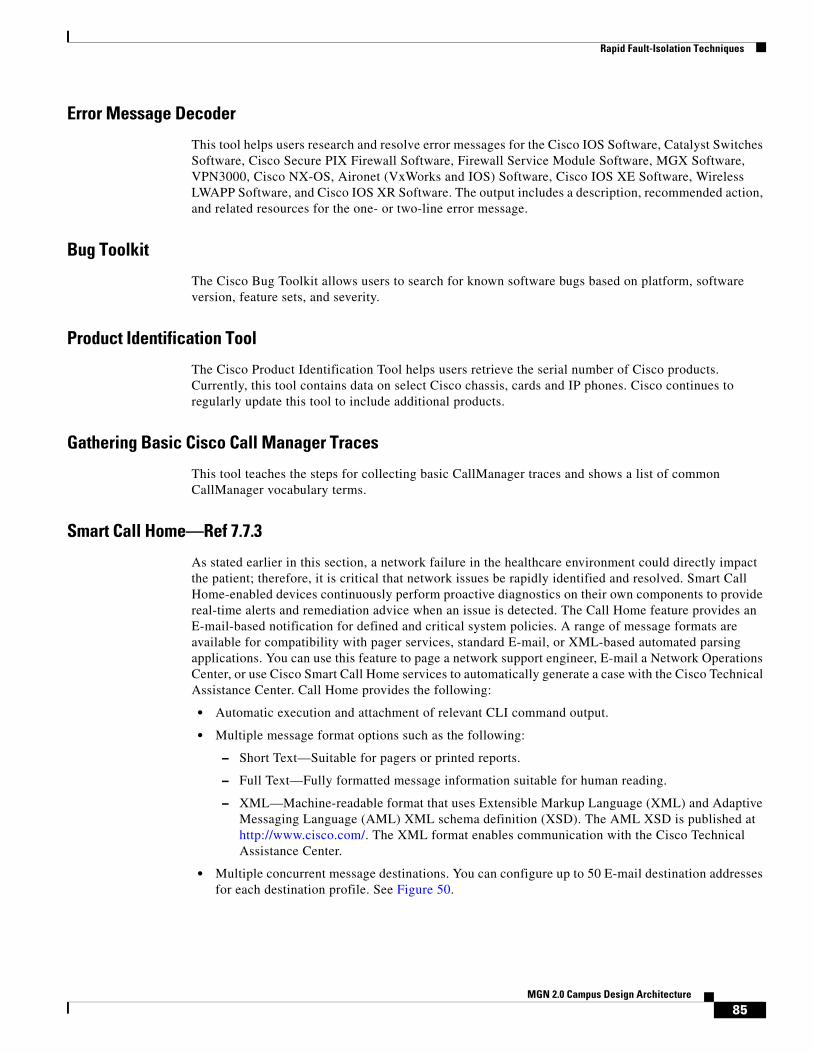
Rapid Fault-Isolation Techniques
Error Message Decoder
This tool helps users research and resolve error messages for the Cisco IOS Software, Catalyst Switches Software, Cisco Secure PIX Firewall Software, Firewall Service Module Software, MGX Software, VPN3000, Cisco NX-OS, Aironet (VxWorks and IOS) Software, Cisco IOS XE Software, Wireless LWAPP Software, and Cisco IOS XR Software. The output includes a description, recommended action, and related resources for the one- or two-line error message.
Bug Toolkit
The Cisco Bug Toolkit allows users to search for known software bugs based on platform, software version, feature sets, and severity.
Product Identification Tool
The Cisco Product Identification Tool helps users retrieve the serial number of Cisco products. Currently, this tool contains data on select Cisco chassis, cards and IP phones. Cisco continues to regularly update this tool to include additional products.
Gathering Basic Cisco Call Manager Traces
This tool teaches the steps for collecting basic CallManager traces and shows a list of common CallManager vocabulary terms.
Smart Call Home—Ref 7.7.3
As stated earlier in this section, a network failure in the healthcare environment could directly impact the patient; therefore, it is critical that network issues be rapidly identified and resolved. Smart Call Home-enabled devices continuously perform proactive diagnostics on their own components to provide real-time alerts and remediation advice when an issue is detected. The Call Home feature provides an E-mail-based notification for defined and critical system policies. A range of message formats are available for compatibility with pager services, standard E-mail, or XML-based automated parsing applications. You can use this feature to page a network support engineer, E-mail a Network Operations Center, or use Cisco Smart Call Home services to automatically generate a case with the Cisco Technical Assistance Center. Call Home provides the following:
• Automatic execution and attachment of relevant CLI command output.
• Multiple message format options such as the following:
– Short Text—Suitable for pagers or printed reports.
– Full Text—Fully formatted message information suitable for human reading.
– XML—Machine-readable format that uses Extensible Markup Language (XML) and Adaptive Messaging Language (AML) XML schema definition (XSD). The AML XSD is published at http://www.cisco.com/. The XML format enables communication with the Cisco Technical Assistance Center.
• Multiple concurrent message destinations. You can configure up to 50 E-mail destination addresses for each destination profile. See Figure 50.
85MGN 2.0 Campus Design Architecture
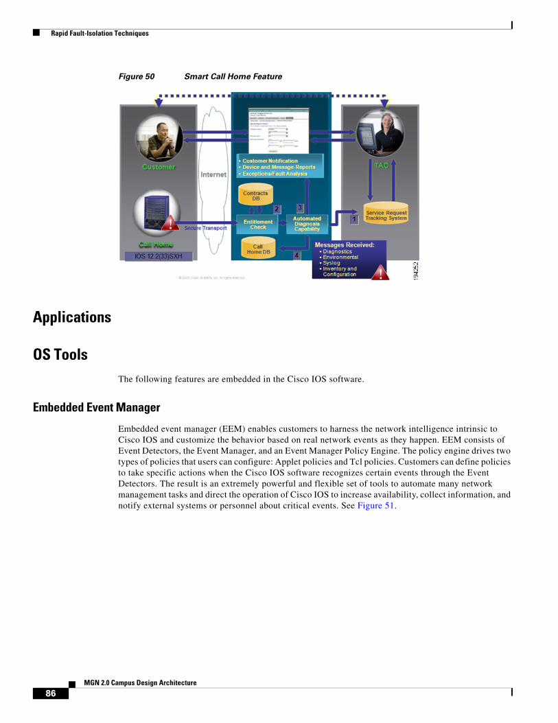
Rapid Fault-Isolation Techniques
Figure 50 Smart Call Home Feature
Applications
OS ToolsThe following features are embedded in the Cisco IOS software.
Embedded Event Manager
Embedded event manager (EEM) enables customers to harness the network intelligence intrinsic to Cisco IOS and customize the behavior based on real network events as they happen. EEM consists of Event Detectors, the Event Manager, and an Event Manager Policy Engine. The policy engine drives two types of policies that users can configure: Applet policies and Tcl policies. Customers can define policies to take specific actions when the Cisco IOS software recognizes certain events through the Event Detectors. The result is an extremely powerful and flexible set of tools to automate many network management tasks and direct the operation of Cisco IOS to increase availability, collect information, and notify external systems or personnel about critical events. See Figure 51.
86MGN 2.0 Campus Design Architecture

Rapid Fault-Isolation Techniques
Figure 51 EEM Architecture
GOLD
Generic Online Diagnostics (GOLD) defines a common framework for diagnostics operations across Cisco platforms running Cisco IOS Software. The GOLD framework specifies the platform-independent fault-detection architecture for centralized and distributed systems. This includes the common diagnostics CLI and the platform-independent fault-detection procedures for boot-up and runtime diagnostics. The platform-specific diagnostics provide hardware-specific fault-detection tests and take appropriate corrective action in response to diagnostics test results. GOLD should also be used to test new hardware when possible. This will help ensure that a faulty component is not inserted into a production environment. See Figure 52.
2294
58
Embedded EventManager Server
TCL Shell
EEM TCL Policy Cisco IOS SubsystemEEM Applet(CLI-based) Policy
ApplicationEvent Detector
“None”Event Detector
CLI
Interface Gold Identity IP SLAResourceThreshold
NeighborDiscovery
SNMPNotification
SNMPObject
IOSWatchdog
MACAddress
ObjectTracking
Syslog
Cisco IOS Infrastructure and Network Subsystems
NetFlow
Routing
XML-RPC RF SNMP
Timer Counter OIR
EventDetectors
87MGN 2.0 Campus Design Architecture

Rapid Fault-Isolation Techniques
Figure 52 GOLD Framework
UDLD
Highly available networks require unidirectional link detection (UDLD) to protect against one-way communication or partially failed links and the effect that they could have on protocols like STP and RSTP. UDLD is typically deployed on any fiber optic interconnection where patch panel errors could cause link up/up with miss matched transmit/receive pairs. It is recommended to use UDLD aggressive mode for best protection. The best practice is to turn on in global configuration to avoid operational error/“misses”. Each switch port configured for UDLD will send UDLD protocol packets (at L2) containing the port's own device/port ID, and the neighbor’s device/port IDs seen by UDLD on that port. Neighboring ports should see their own device/port ID (echo) in the packets received from the other side. If the port does not see its own device/port ID in the incoming UDLD packets for a specific duration of time, the link is considered unidirectional and is shutdown. See Figure 53.
Figure 53 Unidirectional Link
2294
59Hardware Layer
NMS Layer
OnlineDiagnosticsLayer
Gold Subsystem Framework
Platform Specific Diagnostics
Hardware
Remote GUI
Runtime DiagnosticsBoot-UpDiagnostics
Distruptive and NondisruptiveOnline Diagnostics
Nondisruptive HealthMonitoring
On-Demand
MIB/SNMP Trap
NMS Applications
Scheculed Health-Monitoring
Provide GenericDiagnostics and HealthMonitoring Framework
Detect BadHardware
TX
TX
RX
RX
Switch A
Switch B
2286
70
88MGN 2.0 Campus Design Architecture
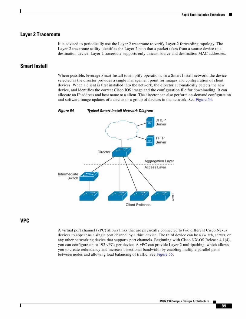
Rapid Fault-Isolation Techniques
Layer 2 Traceroute
It is advised to periodically use the Layer 2 traceroute to verify Layer-2 forwarding topology. The Layer-2 traceroute utility identifies the Layer 2 path that a packet takes from a source device to a destination device. Layer 2 traceroute supports only unicast source and destination MAC addresses.
Smart Install
Where possible, leverage Smart Install to simplify operations. In a Smart Install network, the device selected as the director provides a single management point for images and configuration of client devices. When a client is first installed into the network, the director automatically detects the new device, and identifies the correct Cisco IOS image and the configuration file for downloading. It can allocate an IP address and host name to a client. The director can also perform on-demand configuration and software image updates of a device or a group of devices in the network. See Figure 54.
Figure 54 Typical Smart Install Network Diagram
VPC
A virtual port channel (vPC) allows links that are physically connected to two different Cisco Nexus devices to appear as a single port channel by a third device. The third device can be a switch, server, or any other networking device that supports port channels. Beginning with Cisco NX-OS Release 4.1(4), you can configure up to 192 vPCs per device. A vPC can provide Layer 2 multipathing, which allows you to create redundancy and increase bisectional bandwidth by enabling multiple parallel paths between nodes and allowing load balancing of traffic. See Figure 55.
Aggregation Layer
TFTPServer
Access Layer
IntermediateSwitch
Client Switches
2294
61
DHCPServer
Director
89MGN 2.0 Campus Design Architecture
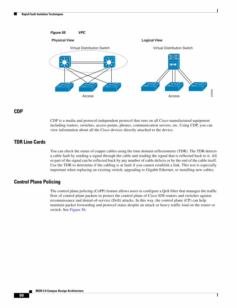
Rapid Fault-Isolation Techniques
Figure 55 VPC
CDP
CDP is a media and protocol-independent protocol that runs on all Cisco manufactured equipment including routers, switches, access points, phones, communication servers, etc. Using CDP, you can view information about all the Cisco devices directly attached to the device.
TDR Line Cards
You can check the status of copper cables using the time domain reflectometer (TDR). The TDR detects a cable fault by sending a signal through the cable and reading the signal that is reflected back to it. All or part of the signal can be reflected back by any number of cable defects or by the end of the cable itself. Use the TDR to determine if the cabling is at fault if you cannot establish a link. This test is especially important when replacing an existing switch, upgrading to Gigabit Ethernet, or installing new cables.
Control Plane Policing
The control plane policing (CoPP) feature allows users to configure a QoS filter that manages the traffic flow of control plane packets to protect the control plane of Cisco IOS routers and switches against reconnaissance and denial-of-service (DoS) attacks. In this way, the control plane (CP) can help maintain packet forwarding and protocol states despite an attack or heavy traffic load on the router or switch. See Figure 56.
2294
62
Virtual Distribution Switch Virtual Distribution Switch
Access Access
Physical View Logical View
90MGN 2.0 Campus Design Architecture

Rapid Fault-Isolation Techniques
Figure 56 Control Plane Policing
MLS Rate Limit
The Catalyst 6500 Sup32 and Sup720 support platform-specific, hardware-based rate limiters for special networking scenarios resembling DoS attacks. These hardware CPU rate limiters are called “special-case” rate limiters because they cover a specific predefined set of IPv4, IPv6, unicast, and multicast DoS scenarios. See Figure 57.
Figure 57 Rate Limit
Line Card
DFC3
Control-PlanePolicing
Special-CasesRate Limiter
RoutingUpdates
2294
63
PFC3
Supervisor Engine
MSFC
Line Card
DFC3
Control-PlanePolicing
Special-CasesRate Limiter
Line Card
SwitchProcessor
RouteProcessor
Layer 2Protocol Data Unit
Layer 2 Protocol TunnelingProtocol Data Unit
... ... PuntTraffic
Management SNMP,Telnet, SSH
... ...
Control-PlanePolicing
Switch Fabric/Bus
Traffic to CPU
Control-PlanePolicing
Special-CasesRate Limiter
2294
64
PFC3/DFC3
Special-CaseTraffic
CPU
SpecialCases
Traffic to CPU
MatchesPolicy
HardwareSpecial-CasesRate Limiter
HardwareControl-Plane
Policing
SoftwareControl-Plane
Policing
91MGN 2.0 Campus Design Architecture

Rapid Fault-Isolation Techniques
Management Plane Protection
The management plane protection (MPP) feature allows a network operator to designate one or more router interfaces as management interfaces. Device management traffic is permitted to enter a device only through these management interfaces. After MPP is enabled, no interfaces except designated management interfaces will accept network management traffic destined to the device.
Mini Protocol Analyzer/WireShark
The Mini Protocol Analyzer captures network traffic from a SPAN session and stores the captured packets in a local memory buffer. Using the provided filtering options, you can limit the captured packets to:
• Packets from selected VLANs, ACLs, or MAC addresses.
• Packets of a specific EtherType.
• Packets of a specified packet size.
You can start and stop the capture using immediate commands, or you can schedule the capture to begin at a specified date and time. The captured data can be displayed on the console, stored to a local file system, or exported to an external server using normal file transfer protocols. The format of the captured file is libpcap, which is supported by many packet analysis and sniffer program.
SPAN/RSPAN/ERSPAN
Use SPAN, RSPAN, and ERSPAN to help diagnose problems. A local SPAN session is an association of source ports and source VLANs with one or more destinations. You configure a local SPAN session on a single switch. Local SPAN does not have separate source and destination sessions. RSPAN supports source ports, source VLANs, and destinations on different switches, which provides remote monitoring of multiple switches across your network. RSPAN uses a Layer 2 VLAN to carry SPAN traffic between switches. ERSPAN supports source ports, source VLANs, and destinations on different switches, which provides remote monitoring of multiple switches across your network. ERSPAN uses a GRE tunnel to carry traffic between switches. See Figure 58, Figure 59, and Figure 60.
Figure 58 Example SPAN Configuration
Port 5 Traffic Mirroredon Port 101
E1E2
E3E4
E5E6 E7
E8E9
E10
E11E12
Network Analyzer
2 3 4 5 6 7 8 9 10 11 12
2294
65
92MGN 2.0 Campus Design Architecture

Rapid Fault-Isolation Techniques
Figure 59 RSPAN Configuration
Figure 60 ERSPAN Configuration
Enhanced Object Tracking
The Enhanced Object Tracking feature provides complete separation between the objects to be tracked and the action to be taken by a client when a tracked object changes. Thus, several clients such as HSRP, VRRP, or GLPB can register their interest with the tracking process, track the same object, and each take different action when the object changes. Each tracked object is identified by a unique number that is specified on the tracking command-line interface (CLI). Client processes use this number to track a specific object. The tracking process periodically polls the tracked objects and notes any change of value. The changes in the tracked object are communicated to interested client processes, either immediately or after a specified delay. The object values are reported as either up or down. The tracking capabilities have been enhanced to enable the configuration of a combination of tracked objects in a list, and a flexible method of combining objects using Boolean logic. The enhancements introduced the following capabilities:
D1 D2
C1 C2
C3
A1 A2
A3
B1 B2
B4
B3
Switch A
Switch C
Switch D
Switch B
Probe
Destination Switch(Data Center)
Intermediate Switch(Distribution)
Source Switch(es)(Access)
2294
66
Layer 2 Trunk Layer 2 Trunk
Layer 2 Trunk
D1 D2
A1 A2
A3
B1 B2
B4
B3
Switch A
Switch D
Switch B
Probe
Destination Switch(Data Center)
Source Switch(es)(Access)
2294
67
RoutedGRE-encapsulatedTraffic
RoutedGRE-encapsulatedTraffic
RoutedGRE-encapsulatedTraffic
RoutedNetwork
93MGN 2.0 Campus Design Architecture

Rapid Fault-Isolation Techniques
• Threshold—The tracked list can be configured to use a weight or percentage threshold to measure the state of the list. Each object in a tracked list can be assigned a threshold weight. The state of the tracked list is determined by whether or not the threshold has been met.
• Boolean “and” function—When a tracked list has been assigned a Boolean “and” function, it means that each object defined within a subset must be in an up state so that the tracked object can become up.
• Boolean “or” function—When the tracked list has been assigned a Boolean “or” function, it means that at least one object defined within a subset must be in an up state so that the tracked object can become up.
Performance Routing
Performance Routing (PfR) complements traditional routing technologies by using the intelligence of a Cisco IOS infrastructure to improve application performance and availability. This technology can select the best path for each application based upon advanced criteria such as, reachability, delay, loss, jitter, and Mean Opinion Score (MOS). Performance Routing can also improve application availability by dynamically routing around network problems like blackholes and brownouts that traditional IP routing may not detect. The intelligent load balancing capability of Performance Routing can optimize path selection based upon link utilization and/or circuit pricing.
Autostate Messaging (6500)
The autostate messaging for rapid link failure detection enables additional communication between the 6500 and service modules to ensure higher availability. The supervisor engine can send autostate messages to the service module about the status of physical interfaces associated with service module VLANs. For example, when all physical interfaces associated with a VLAN go down, the autostate message tells the service module that the VLAN is down. This information lets the service module declare the VLAN as down, bypassing the interface monitoring tests normally required for determining which side suffered a link failure. Autostate messaging provides a dramatic improvement in the time the service module takes to detect a link failure (a few milliseconds as compared to up to 45 seconds without autostate support).
Hardware Components
Power Management
Power Classification
Standards-based Cisco PoE equipment conforms to the IEEE standards for five power classifications for powered devices. When the switch detects a powered device and grants a power request, the switch can adjust the power budget (available power) according to the powered-device IEEE classification. PoE classes describe a range of power used by a specific powered device. Some powered devices require more power than others, and power classes allow switches to manage a power budget or available power. When a powered device is detected and its class is identified, the switch allocates (reserves) the appropriate power range. The switch can determine the IEEE power class of the powered device by applying approximately 20 VDC to the line and measuring the resulting current flow. IEEE-compliant powered devices will produce a very specific current flow in response to the 20 VDC applied by the switch. Table 4 shows the IEEE standard power classes.
94MGN 2.0 Campus Design Architecture

Rapid Fault-Isolation Techniques
Intelligent Power Load Shed
The intelligent load shed is a mechanism used by Cisco StackPower to decide what devices must power down when the available power drops below the allocated power levels. A priority scheme is used to set different levels which become useful when:
• Load shedding in case the power budget falls below the allocated power levels.
• Initial allocation of power to boot up into Cisco IOS Software.
Priorities for powered devices and switches can be changed to values other than the pre-configured default values.
EnergyWise
Cisco EnergyWise allows your Cisco network to act as a platform that can measure, monitor, and manage the way your devices consume energy. From the Cisco EnergyWise perspective, your network has three kinds of devices:
• Endpoints—These are the power consumers. They are typically Power-over-Ethernet (PoE) and non-PoE devices that connect to the network. Increasingly, this category includes nontraditional network devices such as facility controllers, lighting, heating ventilation and air conditioning (HVAC), and so on.
• Domain members—These are the switches, routers, and network controllers that make up the data network proper. They are like endpoints in that they draw power, but they also have the special ability to act together to propagate messages across the network, to form a Cisco EnergyWise domain with other domain members and endpoints. A Cisco EnergyWise domain is much like a community in network management, except that the Cisco EnergyWise domain forms a unit of power management.
• Managers—These are the control applications and devices that use Cisco EnergyWise features to measure, monitor, and manage power consumption. Management solutions can use Cisco EnergyWise queries to act as the point of control for one or more Cisco EnergyWise domains.
Table 4 IEEE Standard Power Classes
IEEE 802.3af Power ClassPower Delivered by Switch Port (in Watts)
Maximum Power Used by Powered Device (in Watts)
Class Signature Current (Typical and Maximum)
0 15.4 12.95 0-4 mA, 6 mA maximum
1 4 3.84 9-12 mA, 14.5 mA maximum
2 7 6.4 17-20 mA, 23 mA maximum
3 15.4 12.95 26-30 mA, 33 mA maximum
4 - - 36-44 mA, 48 mA maximum
95MGN 2.0 Campus Design Architecture

Rapid Fault-Isolation Techniques
Figure 61 EnergyWise
SEA
Make sure that system event archive (SEA) is enabled. The primary method of discovering the cause of system failure is system messages. When system messages do not provide the information needed to determine the cause of a failure, you can enable debug traces and attempt to recreate the failure. However, there are several situations in which neither of the above methods is ideal:
• Reviewing a large number of system messages can be an inefficient method of determining the cause of a failure.
• Debug trace is usually not configured by default.
• You cannot recreate the failure while using debug trace.
• Using debug trace is not an option if the switch on which the failure has occurred is part of your critical network.
SEA enables each of the CPUs on a switch to report events to the management processor using an out-of-band interface. Each event is logged in nonvolatile memory with a time stamp. You can retrieve the event log by accessing the bootflash on the device, or you can copy the log to another location such as a removable storage device. The SEA is a file of up to 32 MB that stores the most recent messages recorded to the log.
Respond
TCP/APIUDPProxy ResponderTCP*
QueryPropagateRespond
Query
Capability
Endpoints
DomainMembers
NetworkManagement
Station
Type
2294
68
IP
96MGN 2.0 Campus Design Architecture

Rapid Fault-Isolation Techniques
OBFL
The OBFL feature gathers boot, environmental, and critical hardware failure data for field-replaceable units (FRUs), and stores the information in the nonvolatile memory of the FRU. This information is used for troubleshooting, testing, and diagnosis if a failure or other error occurs.
Because OBFL is on by default, data is collected and stored as soon as the card is installed. If a problem occurs, the data can provide information about historical environmental conditions, uptime, downtime, errors, and other operating conditions.
Core Dump
A core dump is a binary file that a router creates when it detects an unrecoverable error and needs to reload itself. It is a full copy of the memory image of the router. You need to configure routers in order to create core dumps. However, not all crash types produce core dumps. These are generally useful to Technical Support Representatives and help to identify the cause of the crash.
Cisco Advanced Services
Advanced Services Bug Scrub
A bug scrub is an exercise involving the review of known defects against any software component versions to see if a deployment may be vulnerable to these defects. Cisco Advanced Services can provide further insight into the development process and collaboration between a large number of industry experts in many different vertical-market environments. Typically, the best bug scrubs or candidate management capabilities exist within Cisco Advanced Services, due to the level of expertise and visibility into production software versions running at other organizations.
Code Recommendations
The creation of the periodic Software Infrastructure Analysis Report is a standard deliverable of the Advanced Services Network Optimization Service (NOS). This defined methodology requires that the NCE and the customer work together closely to achieve the full benefit of this deliverable.
A formal approach to periodic Software Infrastructure Analysis helps the customer to understand and appropriately plan for software-related network changes.
This aids a customer proactively in several ways:
• The customer has increased awareness of how software is deployed in their environment and as a result can improve availability by upgrading non-compliant software versions within individual tracks.
• The customer has increased awareness of software risk on a per-track basis and as a result can improve availability and reliability by planning software upgrades before potentially software-impacting events occur.
• The customer can easily understand and visualize Cisco software strategy and thus improve availability and lower operational costs by consolidating software versions or migrating to general deployment software.
97MGN 2.0 Campus Design Architecture

Rapid Fault-Isolation Techniques
Cisco SLA
As customers place more critical applications on their IP Networks, they are demanding that equipment and application vendors stand behind the reliability and availability of their products. Most major new network deals, and a large majority of significant expansions, come with the expectation of Service Level Agreements (SLAs) from equipment vendors. In order to compete effectively for this business and to drive further services revenue, Cisco has been writing customized SLAs for Service Providers, with a current focus on Network Availability SLAs.
The Advanced Services SLA Delivery Solution (SLADS) process goal is to assist the customer in achieving the highest possible level of availability. To achieve this goal, SLADS provides a referenceable, successful Availability SLA implementation and management methodology across accounts. This methodology has been proven in U.S. customer accounts, and should be repeatable for other theatres and customers.
To address this growing need, SLADS provides a standard repeatable process for SLA initiation and management. The processes provide the basis for successful SLA setup, monitoring, and management. See Figure 62.
Figure 62 SLA
Network Analysis
The High Performance Network Analysis is a unique service offering from Cisco Advanced Services leveraging proven methodology and internal engineering tools to perform availability modeling, configuration analysis, and failure impact analysis. Using System Hardware Availability Reliability Calculation (SHARC) and Network Availability Reliability Calculation (NARC) tools, Cisco will perform system-level and network-level availability calculations to provide the availability level of the current IP infrastructure.
Pre-salesQualification
Pre-sales and qualificationdetermined by GAM, SAM,Availability Contract Team
SLA negotiation performed byAvailability Contract Team
Activation dependent on Contract termsin addition to Action register completion
Ongoing SLAManagementActivities
SLA agreedand Signed
Gap Analysisand ActionRegister
(Chapter 3)
AvailabilityManagement(Chapter 5)
SLAManagement(Chapter 6)
HighAvailabilityOperations(Chapter 6)
Pre-assessment(Chapter 2)
SLA ActivationAction RegisterCompletion
Implementing theAvailability Metric
(Chapter 4)
Start
2294
69
98MGN 2.0 Campus Design Architecture

Rapid Fault-Isolation Techniques
The analysis of current configuration files against leading practices leveraging Cisco Network Collector (CNC) helps ensure that optimal configuration parameters are in place to support mission critical IP-based applications and network services. Using OPNET SP Guru Network Planner, modeling and simulation techniques will be used to analyze the resiliency of the IP network and compare network performance measures over a set of user-defined failure scenarios. A set of critical network delivery processes and operations management will be analyzed as well to ensure alignment of support capabilities with network/operations goals.
Network Optimization Services (NOS)
As the platform for enabling business innovation, competitive advantage, and efficiency, your core routing and switching network must be prepared to support new business processes, applications, and technologies. At the same time, the expertise of your team must continue to grow along with it. To help you meet these goals, the Cisco Network Optimization Service combines Network Assessment, Network Support, and Network Learning in a tightly integrated, comprehensive subscription package. This service focuses on optimizing your core routing and switching network to meet future needs and helping your team succeed with new technologies. See Figure 63.
Figure 63 NOS
Cisco Remote Operation Services (CROS)
Cisco Remote Management Services are simple, proactive management solutions for converged networks. Cisco RMS takes full advantage of Cisco’s technology expertise, processes, and tools to help accelerate the business benefits that are possible from Cisco solutions. It simplifies the adoption of advanced and emerging technologies as they are introduced to the complexity of a network and integrates security as a fundamental operating principle.
99MGN 2.0 Campus Design Architecture

References
Cisco RMS services are delivered by experienced teams of engineers who monitor and manage your network 24 hours a day, 365 days a year. The services are based on ITIL processes, which include incident identification, problem management, change management, configuration management, and reporting. The Cisco RMS team employs the unique Cisco Lifecycle approach to services by defining the requisite activities at each phase of the network lifecycle to help reach service excellence.
High Touch Technical Services
The Cisco High-Touch Technical Support Service is a premium service that provides customers with priority access to a designated team of Cisco support engineers 24 hours a day, seven days a week. This team is exceptionally skilled at responding to the critical business needs of high-profile organizations and is available only to Cisco High-Touch Technical Support Service customers. The Cisco High-Touch Technical Support team strives to cultivate a close working relationship with you. This relationship helps the team better understand your network’s operational procedures, past problems, and present concerns. The team has instant access to your business operations information, which is stored in a customer information database. This information aids your support engineers in resolving your network issues more quickly and more efficiently than other technical assistance support can. The high-touch technical support engineer often works with the same customer on a regular basis and becomes very knowledgeable about your network and business environment, providing a more personalized and consistent support (see Table 5). The end results are faster resolution of network issues, improved availability of your essential business systems, and increased overall productivity.
References• Enterprise QoS Solution Reference Network Design Guide Version 3.3
http://www.cisco.com/en/US/docs/solutions/Enterprise/WAN_and_MAN/QoS_SRND/QoS-SRND-Book.html
• Medianet Campus QoS Design 4.0 http://www.cisco.com/en/US/docs/solutions/Enterprise/WAN_and_MAN/QoS_SRND_40/QoSCampus_40.html
• RFC 4594 - Configuration Guidelines for DiffServ Service Classes (Status: Informational)
• Enterprise Mobility 4.1 Design Guide http://www.cisco.com/en/US/solutions/ns340/ns414/ns742/ns820/landing_ent_mob_design.html
Table 5 Activities, Deliverables, and Benefits of Cisco High-Touch Technical Support Service
Activities and Deliverables Benefits
24-hour Access to team and specialized engineers who know your network; local language support available in some regions during business hours; English after hours.
Troubleshooting by experts who are familiar with your network for faster issue-resolution
Network-level support rather than service-based on devices More consistent and personalized support
Possibility of working with the same engineer(s) on a recurrent-basis
A more holistic approach to network maintenance, expanding focus on network infrastructure
Special telephone number for reporting technical issues Expedited access to Cisco experts—calls are routed directly to a special team of Cisco engineers, as applicable
Collection and analysis of information about the customer business operation
Network issues are solved quickly and efficiently, and you can ficus on the day-by-day operations
100MGN 2.0 Campus Design Architecture

References
• Cisco Medical-Grade Network (MGN) 2.0—Wireless Architectures http://www.cisco.com/en/US/docs/solutions/Verticals/Healthcare/MGN_wireless_adg.html
• Wireless and Network Security Integration Solution Design Guide http://www.cisco.com/en/US/docs/solutions/Enterprise/Mobility/secwlandg20/sw2dg.html
• Biomedical Network Admission Control (BNAC) Application Deployment Guide http://www.cisco.com/en/US/docs/solutions/Verticals/Healthcare/bnac_adg.html
101MGN 2.0 Campus Design Architecture

References
102MGN 2.0 Campus Design Architecture