cisco ir800 integrated services router software ... · cisco ir800 integrated services router...
TRANSCRIPT
Cisco IR800 Integrated Services Router Software Configuration GuideDecember 2016
Americas HeadquartersCisco Systems, Inc.170 West Tasman DriveSan Jose, CA 95134-1706 USAhttp://www.cisco.comTel: 408 526-4000
800 553-NETS (6387)Fax: 408 527-0883
Text Part Number:

THE SPECIFICATIONS AND INFORMATION REGARDING THE PRODUCTS IN THIS MANUAL ARE SUBJECT TO CHANGE WITHOUT NOTICE. ALL STATEMENTS, INFORMATION, AND RECOMMENDATIONS IN THIS MANUAL ARE BELIEVED TO BE ACCURATE BUT ARE PRESENTED WITHOUT WARRANTY OF ANY KIND, EXPRESS OR IMPLIED. USERS MUST TAKE FULL RESPONSIBILITY FOR THEIR APPLICATION OF ANY PRODUCTS.
THE SOFTWARE LICENSE AND LIMITED WARRANTY FOR THE ACCOMPANYING PRODUCT ARE SET FORTH IN THE INFORMATION PACKET THAT SHIPPED WITH THE PRODUCT AND ARE INCORPORATED HEREIN BY THIS REFERENCE. IF YOU ARE UNABLE TO LOCATE THE SOFTWARE LICENSE OR LIMITED WARRANTY, CONTACT YOUR CISCO REPRESENTATIVE FOR A COPY.
The following information is for FCC compliance of Class A devices: This equipment has been tested and found to comply with the limits for a Class A digital device, pursuant to part 15 of the FCC rules. These limits are designed to provide reasonable protection against harmful interference when the equipment is operated in a commercial environment. This equipment generates, uses, and can radiate radio-frequency energy and, if not installed and used in accordance with the instruction manual, may cause harmful interference to radio communications. Operation of this equipment in a residential area is likely to cause harmful interference, in which case users will be required to correct the interference at their own expense.
The following information is for FCC compliance of Class B devices: This equipment has been tested and found to comply with the limits for a Class B digital device, pursuant to part 15 of the FCC rules. These limits are designed to provide reasonable protection against harmful interference in a residential installation. This equipment generates, uses and can radiate radio frequency energy and, if not installed and used in accordance with the instructions, may cause harmful interference to radio communications. However, there is no guarantee that interference will not occur in a particular installation. If the equipment causes interference to radio or television reception, which can be determined by turning the equipment off and on, users are encouraged to try to correct the interference by using one or more of the following measures:
• Reorient or relocate the receiving antenna.
• Increase the separation between the equipment and receiver.
• Connect the equipment into an outlet on a circuit different from that to which the receiver is connected.
• Consult the dealer or an experienced radio/TV technician for help.
Modifications to this product not authorized by Cisco could void the FCC approval and negate your authority to operate the product.
The Cisco implementation of TCP header compression is an adaptation of a program developed by the University of California, Berkeley (UCB) as part of UCB’s public domain version of the UNIX operating system. All rights reserved. Copyright © 1981, Regents of the University of California.
NOTWITHSTANDING ANY OTHER WARRANTY HEREIN, ALL DOCUMENT FILES AND SOFTWARE OF THESE SUPPLIERS ARE PROVIDED “AS IS” WITH ALL FAULTS. CISCO AND THE ABOVE-NAMED SUPPLIERS DISCLAIM ALL WARRANTIES, EXPRESSED OR IMPLIED, INCLUDING, WITHOUT LIMITATION, THOSE OF MERCHANTABILITY, FITNESS FOR A PARTICULAR PURPOSE AND NONINFRINGEMENT OR ARISING FROM A COURSE OF DEALING, USAGE, OR TRADE PRACTICE.
IN NO EVENT SHALL CISCO OR ITS SUPPLIERS BE LIABLE FOR ANY INDIRECT, SPECIAL, CONSEQUENTIAL, OR INCIDENTAL DAMAGES, INCLUDING, WITHOUT LIMITATION, LOST PROFITS OR LOSS OR DAMAGE TO DATA ARISING OUT OF THE USE OR INABILITY TO USE THIS MANUAL, EVEN IF CISCO OR ITS SUPPLIERS HAVE BEEN ADVISED OF THE POSSIBILITY OF SUCH DAMAGES.
Cisco and the Cisco logo are trademarks or registered trademarks of Cisco and/or its affiliates in the U.S. and other countries. To view a list of Cisco trademarks, go to this URL: www.cisco.com/go/trademarks. Third-party trademarks mentioned are the property of their respective owners. The use of the word partner does not imply a partnership relationship between Cisco and any other company. (1110R)
Any Internet Protocol (IP) addresses and phone numbers used in this document are not intended to be actual addresses and phone numbers. Any examples, command display output, network topology diagrams, and other figures included in the document are shown for illustrative purposes only. Any use of actual IP addresses or phone numbers in illustrative content is unintentional and coincidental.
Cisco IR800 Integrated Services Router Software Configuration Guide© 2016 Cisco Systems, Inc. All rights reserved.

Contents
C H A P T E R 2 Product Overview 2-3
General Description 2-3
Hardware Overview 2-4
IR829 Product Overview 2-4
IR809 Product Overview 2-8
Reset Button 2-11
Booting a Default IOS Image and Default Configuration 2-12
Software Overview 2-13
Hardware Differences Between IR809, IR829, and the C819HG 2-14
Hardware Comparison 2-15
Antenna Recommendations 2-16
Features Supported in Different IOS Releases 2-16
Related Documentation 2-17
C H A P T E R 3 Initial Configuration 3-18
IR800 Bootstrap Sequence and Troubleshooting 3-18
Sequence 1 3-19
Sequence 2 3-21
Setup Command Facility 3-22
Verifying the Initial Configuration 3-25
LEDs 3-25
Single Modem 3-25
Dual Modem 3-26
Software Bundle Installation 3-29
Power Over Ethernet (PoE) 3-30
Where To Go From Here 3-31
C H A P T E R 4 Cellular Interface Modules 4-32
Cellular Interface 4-33
4G LTE Dual SIMs 4-33
Dual Radio Configuration and Single Radio Configuration 4-34
Verizon Profile 4-38
AT&T Profile 4-38
Creating a Cellular Profile for Verizon. 4-39
Creating a Cellular Profile for AT&T 4-40
Other Useful Commands 4-42
Accessing 4G Modem AT Commands 4-43
Checking 4G Modem Firmware through AT Commands 4-44
1Cisco IR800 Integrated Services Router Software Configuration Guide
Contents
IR800 Cellular Technology Selection 4-44
GPS 4-47
Troubleshooting the Cellular Interface 4-48
C H A P T E R 5 IR829 AP803 Access Point Module 5-52
Hardware Overview 5-52
Software Overview 5-52
IOS Internal Interfaces 5-53
IR829 IOS – AP803 Console Access 5-54
IR829 Service Module 5-55
AP803 Embedded Web Manager 5-55
Upgrading the Firmware on the AP803 5-56
C H A P T E R 6 Configuring Virtual-LPWA 6-58
Configuring VLPWA Interface on the IR800 Series 6-59
Configuring Ethernet Interface and Creating VLPWA Interface 6-59
Configuring IR809 for One Cisco LoRaWAN Interface Module 6-59
Configuring IR809 for Multiple Cisco LoRaWAN Interface Modules 6-60
Configuring IR829 6-60
Configuring DHCP Pool for the Cisco LoRaWAN Interface Module 6-61
Configuring SNMP TRAP for Modem Notifications 6-63
Configuring VLPWA Interface and Associated Cisco LoRaWAN Interface Module 6-64
Configuring IR809 for One Cisco LoRaWAN Interface Module 6-64
Configuring Cisco LoRaWAN Interface Module Password 6-65
Configuring Console Access 6-65
Configuring Clock for the Cisco LoRaWAN Interface Module 6-65
Configuring NTP Server for the Cisco LoRaWAN Interface Module 6-66
Configuring GPS as the Clock Source 6-66
Configuring Cisco LoRaWAN Interface Module Timezone 6-67
Configuring IPSec on the Cisco LoRaWAN Interface Module 6-67
Configuring SCEP on the Cisco LoRaWAN Interface Module 6-68
Configuring Security Protection 6-69
Managing the Cisco LoRaWAN Interface Module 6-69
LoRaWAN Modem Firmware Upgrade 6-70
Installing U-boot 6-71
LoRaWAN Modem FPGA Upgrade 6-71
Uploading a File to the LoRaWAN Modem 6-72
2Cisco IR800 Integrated Services Router Software Configuration Guide

Contents
Monitoring the LoRaWAN Modem 6-73
Monitoring LED Status 6-76
Checking Connectivity 6-76
Debugging the LoRaWAN Modem 6-77
C H A P T E R 7 Alarms 7-78
Finding Feature Information 7-78
Information About Alarms 7-78
Alarm Port 7-78
Alarm Conditions 7-79
Configuration Commands 7-79
Configuration Examples 7-80
Enabling SNMP Traps 7-81
MIBs 7-81
C H A P T E R 8 Guest Operating System (Guest OS) Installation and Configuration 8-82
Guest Operating System Overview 8-82
Prerequisites 8-83
Guidelines and Limitations 8-83
Default Settings 8-84
Installation and Upgrade 8-84
Configuring Cisco IOS 8-85
Configuring the IR800 Ethernet Interface 8-85
IPv6 Gigabit Ethernet 8-85
Enabling IPv4 Gigabit Ethernet 8-86
Configuring DHCP Pool 8-86
Configuring Guest OS GigabitEthernet on Cisco IOS 8-87
VDS Configuration 8-87
Enabling Virtual Guest OS Console 8-88
Configuring Guest OS 8-88
Starting Guest OS 8-88
Accessing Virtual Guest OS Console 8-89
Setting the Root Password 8-89
Enabling Remote SSH Access 8-89
Configuring Network Address Translation (NAT) 8-90
IR800 Guest-OS USB Access from IOS 8-91
IR800 IOS SCP From/To Guest-OS USB Storage 8-92
New for IOS 15.6(1)T 8-92
3Cisco IR800 Integrated Services Router Software Configuration Guide

Contents
New for IOS 15.6(3)M 8-93
USB Support 8-93
Serial Device Configuration 8-93
Serial Relay Configuration 8-93
Memory Allocation Optimization 8-94
Troubleshooting 8-94
Checking Connectivity 8-95
Related Documentation 8-95
C H A P T E R 9 WAN Monitoring 9-97
Information About WANMon 9-97
Built-in Recovery Actions 9-98
Prerequisites 9-98
Guidelines and Limitations 9-99
Configuring WANMon 9-99
Verifying WANMon Configuration 9-101
Configuration Examples 9-101
WANMon Cellular Interface Configuration Example 9-101
Multiple WAN Link Monitoring Example 9-101
Related Documentation 9-102
C H A P T E R 10 Ignition Power Management 10-103
Features of Ignition Power Management 10-103
Command Line Interface (CLI) 10-104
Configuration CLI 10-104
Status CLI 10-104
Troubleshooting CLI 10-104
Command Examples 10-106
Default Values 10-106
C H A P T E R 11 Licensing and Security 11-108
Licensing 11-108
Licensing CLI 11-109
Hardware Crypto Support 11-109
C H A P T E R 12 Network Management Solutions 12-111
Cisco IoT Field Network Director (formerly referred to as CG-NMS) 12-111
4Cisco IR800 Integrated Services Router Software Configuration Guide

Contents
Cisco Prime Infrastructure 12-112
Davra RuBAN 12-113
Cisco IoT Fog Director 12-113
About Cisco IOx 12-113
About Cisco Fog Director 12-113
OID and Inventory 12-114
5Cisco IR800 Integrated Services Router Software Configuration Guide
Preface
This preface describes the objectives, audience, organization, and conventions of this guide and describes related documents that have additional information. It contains the following sections:
• Objective, page 1
• Audience, page 1
• Conventions, page 1
• Searching Cisco Documents, page 2
• Obtaining Documentation and Submitting a Service Request, page 2
ObjectiveThis guide provides an overview of the software features and explains how to perform the configuration steps for the Cisco IR800 Integrated Services Routers.
AudienceThis guide is intended for people who have a high level of technical ability, although they may not have experience with Cisco software.
ConventionsThis section describes the conventions used in this guide.
Note Means reader take note. Notes contain helpful suggestions or references to additional information and material.
Caution This symbol means reader be careful. In this situation, you might do something that could result in equipment damage or loss of data.
1Cisco IR800 Integrated Services Router Software Configuration Guide
Preface
Tip Means the following information will help you solve a problem. The tip information might not be troubleshooting or even an action, but could be useful information.
Searching Cisco DocumentsTo search an HTML document using a web browser, press Ctrl-F (Windows) or Cmd-F (Apple). In most browsers, the option to search whole words only, invoke case sensitivity, or search forward and backward is also available.
To search a PDF document in Adobe Reader, use the basic Find toolbar (Ctrl-F) or the Full Reader Search window (Shift-Ctrl-F). Use the Find toolbar to find words or phrases within a specific document. Use the Full Reader Search window to search multiple PDF files simultaneously and to change case sensitivity and other options. Adobe Reader’s online help has more information about how to search PDF documents.
Obtaining Documentation and Submitting a Service RequestFor information on obtaining documentation, submitting a service request, and gathering additional information, see the monthly What’s New in Cisco Product Documentation, which also lists all new and revised Cisco technical documentation, at:
http://www.cisco.com/en/US/docs/general/whatsnew/whatsnew.html
Subscribe to the What’s New in Cisco Product Documentation as a Really Simple Syndication (RSS) feed and set content to be delivered directly to your desktop using a reader application. The RSS feeds are a free service and Cisco currently supports RSS Version 2.0.
2Cisco IR800 Integrated Services Router Software Configuration Guide

Cisco IR800 Integr
C H A P T E R 2
Product OverviewThis chapter provides an overview of the features available for the Cisco IR800 Integrated Services Routers (ISRs) and contains the following sections:
• General Description, page 2-3
• Hardware Overview, page 2-4
– IR829 Product Overview, page 2-4
– IR809 Product Overview, page 2-8
– Reset Button, page 2-11
• Software Overview, page 2-13
• Hardware Differences Between IR809, IR829, and the C819HG, page 2-14
• Antenna Recommendations, page 2-16
• Features Supported in Different IOS Releases, page 2-16
• Related Documentation, page 2-17
General DescriptionThe 800 Series Industrial Integrated Services Routers are compact, ruggedized, Cisco IOS Software routers. They offer support for integrated 4G LTE wireless WAN (both 809 and 829 models) and wireless LAN capabilities (829 model only). The IR829 offers an Internal WLAN Access Point which runs on-board the router. The AP803 runs its own IOS software independently from the IR829 IOS, and requires configuring. The AP803 works as a standalone access point or with a wireless controller.
They offer:
• Easily and rapidly deployable
• Highly available, highly secure, and reliable
• Designed for machine-to-machine (M2M) communication and for mobile vehicle communication in harsh environmental conditions
• Designed to withstand hostile environments, tolerating a wide temperature range
These industrialized routers deliver enterprise-class features, including highly secure data, voice, and video communications to stationary and mobile network nodes across wired and wireless links. They can deliver enterprise-grade, wireline-like functionality.
2-3ated Services Router Software Configuration Guide

Chapter 2 Product Overview Hardware Overview
The routers also support Cisco IOx Software, providing an open, extensible environment for hosting additional operating systems and applications directly at the network edge. They can enhance other Cisco IoT System products across multiple industries, including transportation, manufacturing, electrical utilities, and others.
For a complete listing of the routers capabilities, see the Cisco 829 Industrial Integrated Services Routers Product Information.
Hardware OverviewThis section covers the overview of the IR809 and IR829.
IR829 Product OverviewFigure 2-1 shows the IR829.
Figure 2-1 Cisco IR829 Integrated Services Router
Figure 2-2 shows the front panel details of the Cisco IR829 Single Modem.
Figure 2-2 Cisco IR829 Front Panel Single Modem
2-4Cisco IR800 Integrated Services Router Software Configuration Guide
Chapter 2 Product Overview Hardware Overview
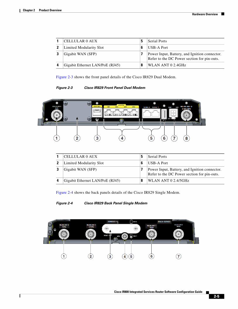
Figure 2-3 shows the front panel details of the Cisco IR829 Dual Modem.
Figure 2-3 Cisco IR829 Front Panel Duel Modem
Figure 2-4 shows the back panels details of the Cisco IR829 Single Modem.
Figure 2-4 Cisco IR829 Back Panel Single Modem
1 CELLULAR 0 AUX 5 Serial Ports
2 Limited Modularity Slot 6 USB-A Port
3 Gigabit WAN (SFP) 7 Power Input, Battery, and Ignition connector. Refer to the DC Power section for pin-outs.
4 Gigabit Ethernet LAN/PoE (RJ45) 8 WLAN ANT 0 2.4GHz
1 CELLULAR 0 AUX 5 Serial Ports
2 Limited Modularity Slot 6 USB-A Port
3 Gigabit WAN (SFP) 7 Power Input, Battery, and Ignition connector. Refer to the DC Power section for pin-outs.
4 Gigabit Ethernet LAN/PoE (RJ45) 8 WLAN ANT 0 2.4/5GHz
2-5Cisco IR800 Integrated Services Router Software Configuration Guide

Chapter 2 Product Overview Hardware Overview
Figure 2-5 shows the back panels details of the Cisco IR829 Dual Modem.
Figure 2-5 Cisco IR829 Back Panel Dual Modem
Note Behind the SIM Door Assembly, there is a reset switch (1), Mini USB console port (2), and Dual SIM slots (3). See Figure 2-6 for details
1 WLAN ANT 0 5GHz 5 Denotes SIM card order, SIM0 on top and SIM1 on bottom.
2 WLAN ANT 1 2.4GHz 6 WLAN ANT 1 5GHz
3 Cover over SIM cards, reset button and console port cover, see Figure 2-6
7 CELLULAR 0 MAIN
4 GPS SMA
1 Cellular 1 Main 5 Denotes SIM card order, SIM0 on top and SIM1 on bottom.
2 WLAN ANT 1 2.4/5GHz 6 Cellular 1 AUX
3 Cover over SIM cards, reset button and console port cover, see Figure 2-6
7 CELLULAR 0 MAIN
4 GPS SMA
2-6Cisco IR800 Integrated Services Router Software Configuration Guide
Chapter 2 Product Overview Hardware Overview
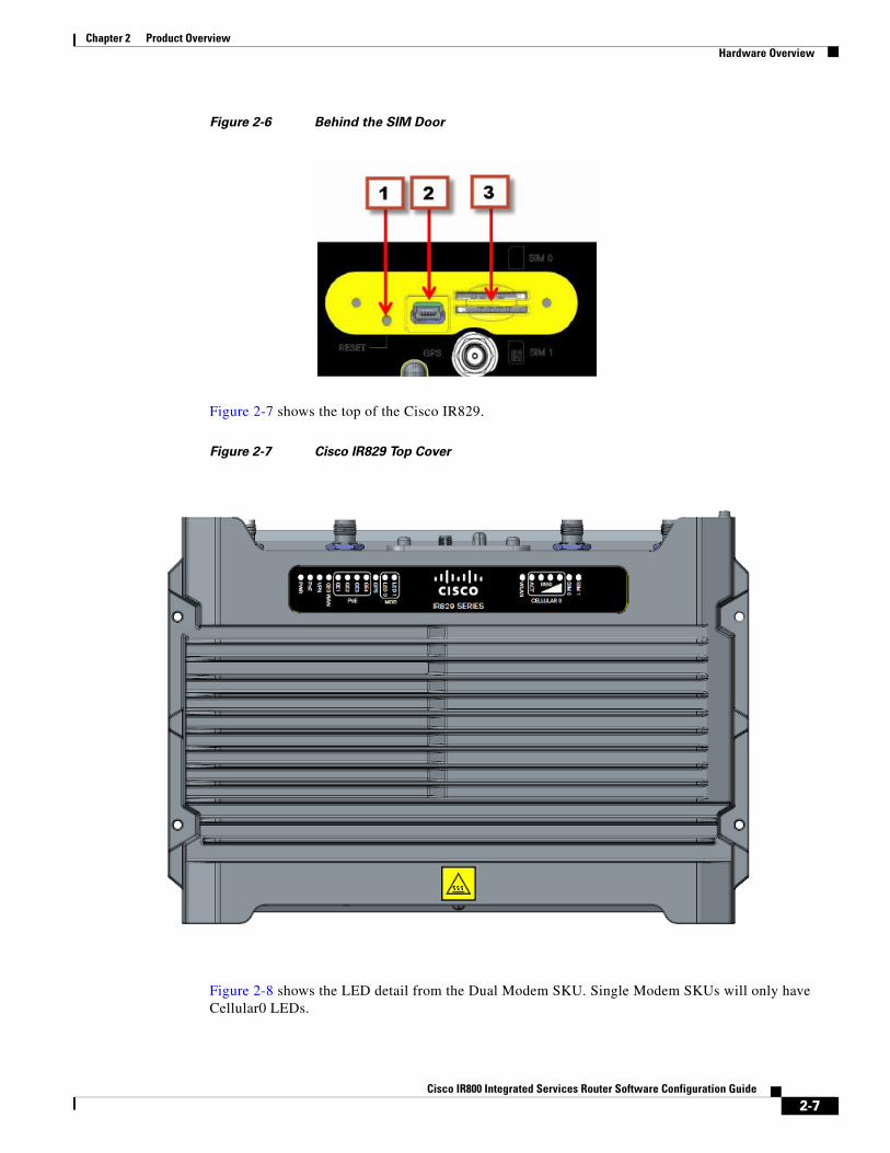
Figure 2-6 Behind the SIM Door
Figure 2-7 shows the top of the Cisco IR829.
Figure 2-7 Cisco IR829 Top Cover
Figure 2-8 shows the LED detail from the Dual Modem SKU. Single Modem SKUs will only have Cellular0 LEDs.
2-7Cisco IR800 Integrated Services Router Software Configuration Guide
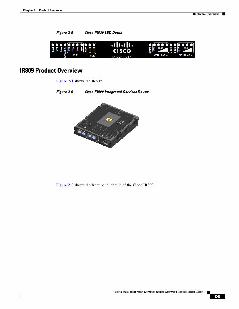
Chapter 2 Product Overview Hardware Overview
Figure 2-8 Cisco IR829 LED Detail
IR809 Product OverviewFigure 2-1 shows the IR809.
Figure 2-9 Cisco IR809 Integrated Services Router
Figure 2-2 shows the front panel details of the Cisco IR809.
2-8Cisco IR800 Integrated Services Router Software Configuration Guide
Chapter 2 Product Overview Hardware Overview
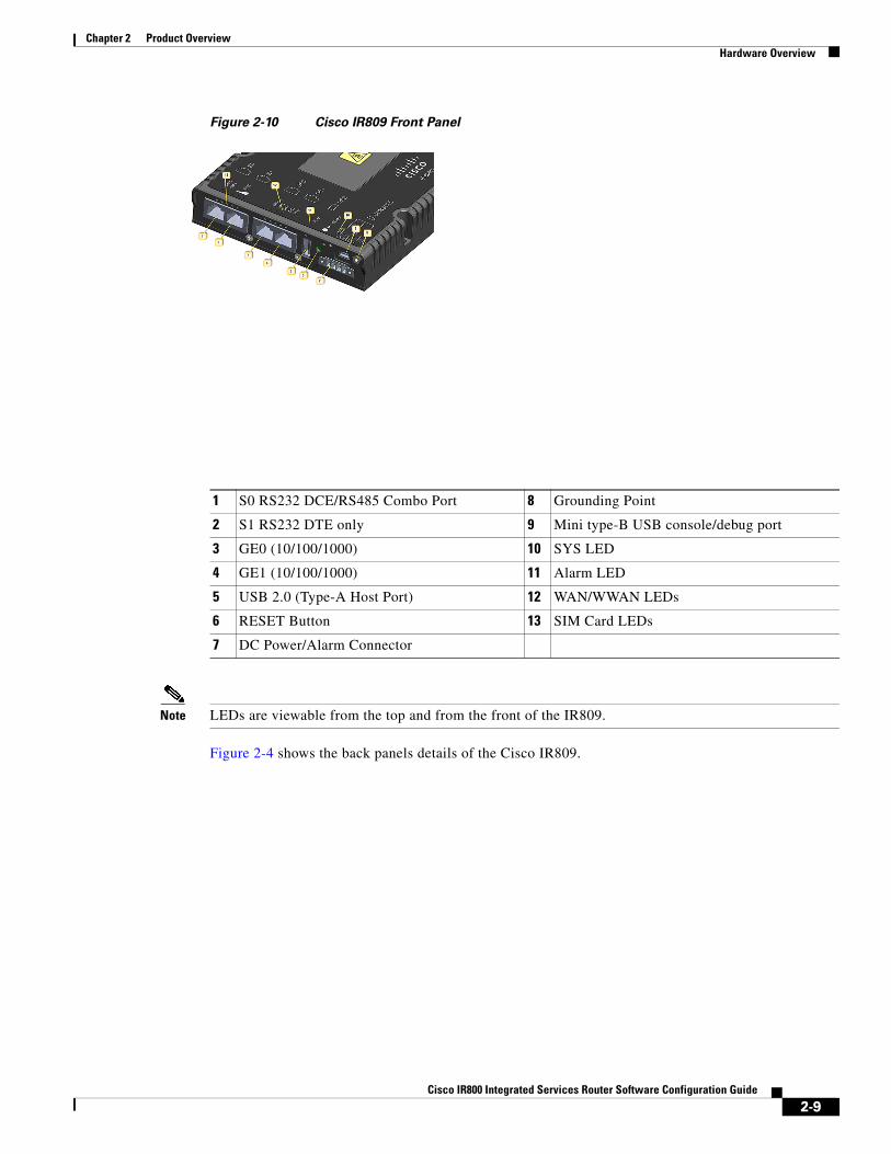
Figure 2-10 Cisco IR809 Front Panel
Note LEDs are viewable from the top and from the front of the IR809.
Figure 2-4 shows the back panels details of the Cisco IR809.
1 S0 RS232 DCE/RS485 Combo Port 8 Grounding Point
2 S1 RS232 DTE only 9 Mini type-B USB console/debug port
3 GE0 (10/100/1000) 10 SYS LED
4 GE1 (10/100/1000) 11 Alarm LED
5 USB 2.0 (Type-A Host Port) 12 WAN/WWAN LEDs
6 RESET Button 13 SIM Card LEDs
7 DC Power/Alarm Connector
2-9Cisco IR800 Integrated Services Router Software Configuration Guide
Chapter 2 Product Overview Hardware Overview
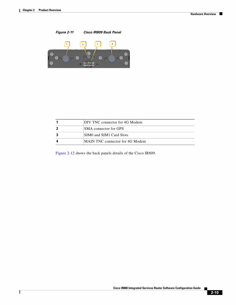
Figure 2-11 Cisco IR809 Back Panel
Figure 2-12 shows the back panels details of the Cisco IR809.
1 DIV TNC connector for 4G Modem
2 SMA connector for GPS
3 SIM0 and SIM1 Card Slots
4 MAIN TNC connector for 4G Modem
2-10Cisco IR800 Integrated Services Router Software Configuration Guide

Chapter 2 Product Overview Hardware Overview
Figure 2-12 Cisco IR809 Top Cover
Note See the respective Hardware Installation Guides for detailed description of the LEDs.
Reset ButtonThe reset button resets the router configuration to the default configuration set by the factory. To restore the router configuration to the default configuration set by the factory, use a standard size #1 paper clip with wire gauge 0.033 inch or smaller and simultaneously press the reset button while applying power to the router.
Note On the IR829, the rear cover must be removed to expose the reset switch.
Starting with release 15.6(1)T, the IR809 and IR829 have changed the way the reset button works. The IR800 series platforms now perform in the same manner as the C819. The high level description of the functionality works like this:
• Press and hold the reset button while powering up the router
• During warm reboot this button has no impact on performance
• Simply pressing the button at any time does not reset the router
• The router will not react to the reset button if it is pressed after power-up because the button needs to be pushed before turning ON/inserting power – to make sure that the condition is detected.
• The push-button cannot be used to boot a IOS image from network. The golden image has to be on flash: only
2-11Cisco IR800 Integrated Services Router Software Configuration Guide

Chapter 2 Product Overview Hardware Overview
Note For the location of the reset button see the appropriate IR809 or IR829 Hardware Installation Guide.
Perform the following steps to use this feature:
Step 1 Unplug power.
Step 2 Press the reset button on the router.
Step 3 Power up the system while holding down the reset button.
The system LED blinks four times indicating that the router has accepted the button push.
Tip The IR800 series of routers do not support password recovery. If needed, use the above procedure to bring the router to its initial configuration, or to a previously set backup configuration.
Booting a Default IOS Image and Default Configuration
The IR800 differs from traditional IOS routers when booting a default IOS image and a default configuration. These steps apply on a device running 15.6(1)T or later.
Method 1:
Step 1 Save a copy of your IR800 IOS image with the .default extension on flash. For example: ios-image.default.
Step 2 Save a copy of your IR800 Hypervisor image with the .default extension on bootstrap. For example: hypervisor-image.default.
Step 3 Save your desired default configuration file with the .cfg extension on flash. For example: config.cfg.
Step 4 Reset your IR800 router by powering it down, then press and hold the RESET button while powering up the device.
The IR800 router will automatically boot hypervisor-image.default, then ios-image.default, and load the config.cfg.
Step 5 Make sure there exists only one IOS image with a .default extension, only one configuration file with the .cfg extension on the flash, and only one hypervisor image with the .default extension on bootstrap.
If you do not have a config.cfg on flash, it will boot with the Cisco default configuration (aka: empty) startup-config.
Method 2:
Step 1 Check the “boot system” setting configuration in the default configuration file (prior to saving it to startup-config), and verify that it points to an existing IOS image on the flash: partition.
2-12Cisco IR800 Integrated Services Router Software Configuration Guide

Chapter 2 Product Overview Software Overview
Note If that particular IOS image is not present, the device will drop in rommon-2 mode and you will need to manually boot an IOS image from there.
Step 2 Copy your desired default config file to the startup-config.
Step 3 Reload the router. Do NOT enter Yes if prompted whether you want to save the running-config to startup-config.
Note To simplify the boot process, the IR800 routers do not support the ROMMON configuration register and the associated CLI commands. The IR800 either boots the pre-configured images, or stops at the ROMMON prompt for user intervention. In the event of a boot failure, see Chapter 3, “IR800 Bootstrap Sequence and Troubleshooting” for additional information.
An example of the log activity after a reboot follows:
IR800# show log *Nov 30 19:31:04.925: %LINEPROTO-5-UPDOWN: Line protocol on Interface GigabitEthernet0, changed state to down*Nov 30 19:31:10.651: %PLATFORM-5-RESET_BUTTON: Reset Button pressed during boot up.*Nov 30 19:31:11.527: %LINK-3-UPDOWN: Interface Async0, changed state to up*Nov 30 19:31:11.595: %SYS-5-RESTART: System restarted --Cisco IOS Software, ir800 Software (ir800-UNIVERSALK9-M), Version 15.6(1)T, RELEASE SOFTWARE (fc1)
Software OverviewThe IR800 series offers a rich IOS feature set. This section provides a brief overview of these features.
Note Features may be dependent of platform and releases
Feature Description
Cellular Connectivity • 4G LTE, 3.7G, 3.5G, or 3G Cellular WAN link
• External, dual 4G antennas with main and receive diversity for maximum signal strength connectivity
• Dual subscriber identity module (SIM) capability
Wi-Fi (829 only) • Dual radio 802.11n concurrent 2.4 GHz and 5.0 GHz with embedded 2X3 MIMO
• Up to 300 Mbps data rate per radio
Cisco IOx Application Support Provides an open, extensible environment for hosting OS and applications at the network edge; expansion module slot to enable additional future communication technologies.
2-13Cisco IR800 Integrated Services Router Software Configuration Guide

Chapter 2 Product Overview Hardware Differences Between IR809, IR829, and the C819HG
Hardware Differences Between IR809, IR829, and the C819HGThe IR809 is a very compact cellular (3G and 4G/LTE) industrial routers for remote deployment in various industries. They enable reliable and secure cellular connectivity for remote asset monitoring and machine-to-machine (M2M) solutions such as distribution automation, pipeline monitoring, and roadside infrastructure monitoring.
Security Advanced security features that support:
• Access control
• Data confidentiality and data privacy
• Threat detection and mitigation
• Device and platform integrity
Cisco IOT Field Network Director
Available as the optional Cisco Industrial Operations Kit. This is a software platform that manages a multiservice network and security infrastructure for IoT applications such as transportation, smart grid, services, distribution automation and substation automation.
Cisco IOS Mobile IP Features • Mobile IP offers transparent roaming for mobile networks, establishing a transparent Internet connection regardless of location or movement. This enables mission-critical applications to stay connected even when roaming between networks.
• Assigned IP addresses to the home network are maintained in private or public networks.
Cisco IOS Mobile Network Features
Allows an entire subnet or mobile network to maintain connectivity to the home network while roaming.
QoS Features • Provides traffic precedence to delay-sensitive or prioritized applications.
• Facilitates low-latency routing of delay-sensitive industrial applications.
Management and Manageability
• Network managers can remotely manage and monitor networks with SNMP, Telnet, or HTTP/HTTPS/SSH, and locally through a console port.
• Support for extensive 3G and 4G LTE-based MIBs allows for centralized management of remote devices and gives network managers visibility into and control over the network configuration at the remote site.
• Network managers can reset to a predesignated golden image, as well as configure an 829 through Cisco IOS Software or through an external reset button.
• Network managers can upgrade 3G, 3.5G, 3.7G, and 4G LTE firmware and router configurations remotely.
The tight integration with Cisco IOS Software enables router to self-monitor the LTE WAN link and automatically recover from a radio link failure.
Cisco IOS Software Requirement
• Cisco IOS Software feature set: Universal Cisco IOS Software
• Cisco IOS Software Release - 15.5(3)M, or later, and modem firmware - 5.5.58, or later
Feature Description
2-14Cisco IR800 Integrated Services Router Software Configuration Guide

Chapter 2 Product Overview Hardware Differences Between IR809, IR829, and the C819HG
The IR829 is a highly ruggedized compact cellular (3G and 4G LTE with GPS and dual SIM) and WLAN (2.4/5GHz) industrial routers supporting for scalable, reliable, and secure management of fleet vehicles and mass transit applications.
The 819HG-LTE-MNA-K9: Multimode Cisco LTE 2.0 for carriers that operate LTE 700 MHz (band 17), 1900 MHz (band 2 PCS), 850 MHz (band 5), 700 MHz (band 13), 1900 MHz (band 25 extended PCS) networks; or 1700/2100 MHz (band 4 AWS) networks; backward-compatible with UMTS and HSPA+: 850 MHz (band 5), 900 MHz (band 8), 1900 MHz (band 2 PCS), and 1700/2100 MHz (band 4 AWS), with EVDO Rev A/CDMA 1x BC0, BC1, BC10.
Hardware Comparison
Feature IR809 IR829 C819HG
OIR of SIM Yes Yes Yes
Guest OS Support Yes Yes Yes
2G/3G/4G Support Yes, dual SIM support, SKUs available per region
See the Chapter 4, “Cellular Interface”for additional information.
819(H)G-4G supports dual-SIM Different SKU’s per region.
SW MC 7750,7700,7710
USB Flash Yes Yes No
USB type A Interface Yes Yes No
Console Port Mini USB Mini USB RJ-45
Alarm Port One Alarm input on IR809 No No
IEEE 802.11a/b/g/n WiFi No Yes, depending on the platform type.
No
Power Requirements Nominal voltage: 12-48V DC
Min/max voltage: 9.6 – 60V DC input
Max, Min current: 3A, 0.5A
Nominal voltage: 12V, 24V DC
Min/max voltage: 9-32V DC input
Max/Min current: 7.8 A, 2.8 A
Maximum power consumption: 40 W (no PoE) and 70W (PoE)
Nominal voltage: 12V, 24V DC
Min/max voltage: 10-36V DC
Maximum power consumption: 26W
Ethernet Ports 2 x RJ45 10/100/1000Mbs 4 x RJ45 10/100/1000Mbs
1 x SFP 1000Mbs
4 x RJ45 10/100 Mbs
1 x GE 10/100/1000Mbs
Serial Ports 2 x RJ45 (1xRS-232 and 1xRS232/RS-485 12 in 1 Smart Serial
Antenna: Main, Diversity and GPS
Yes Yes 819(H)G-4G has Active GPS SMA Connector and option for 2 4G antennas
2-15Cisco IR800 Integrated Services Router Software Configuration Guide

Chapter 2 Product Overview Antenna Recommendations
Antenna RecommendationsNeither the IR809 or IR829 are shipped with antennas. They must be ordered separately. The IR829 must be installed with 2 antennas (Main & Aux) to guarantee the best performance level. Using a single antenna may impact the downlink performance by a minimum 3dB, and can be much greater (10-20dB) due to multipath fading (destructive interference between direct and reflected radio waves).
In case of 3G UMTS, a solo antenna would not be able to switch to the diversity port.
With the IR829, it must be guaranteed >15dB isolation between the WiFi and LTE antennas at all frequencies of 4G LTE and WiFi operation, for minimum impact to performance. This is ideally 20-25dB.
The Sierra Wireless MC73xx modem series supports MIMO on LTE. WCDMA UMTS HSPA DC-HSPA+ is diversity only, without MIMO.
Note Poorly installed MIMO antennas, such that the two (or more in case of 3x3, 4x4 MIMO) antennas have a strong correlation coefficient. This may cause the two streams to interfere with each other (otherwise known as lack of diversity), since the system has trouble separating the two. The multi-element antennas (5-in-1, 3-in-1, 2-in-1) have good diversity
For detailed information about Cisco Antennas, please refer to the following guides:
Cisco Industrial Routers Antenna Guide:
http://www.cisco.com/c/en/us/td/docs/routers/connectedgrid/antennas/installing-combined/industrial-routers-antenna-guide.html
Connected Grid Antennas Installation Guide:
http://www.cisco.com/c/en/us/td/docs/routers/connectedgrid/antennas/installing/cg_antenna_install_guide.html
Cisco Aironet Antennas and Accessories Reference Guide
http://www.cisco.com/c/en/us/products/collateral/wireless/aironet-antennas-accessories/product_data_sheet09186a008008883b.html
Features Supported in Different IOS ReleasesThe IR800 series was originally released with IOS software version 15.5(3)M. The following lists the software releases with the features added.
15.5(3)M (initial release)
• Software based Crypto
15.5(3)Mx
• Hardware based Crypto
15.6(1)T
• IR809 Input alarm port, including SNMP Trap support
• SLIP & PPP serial encapsulation on serial interfaces
• Reset button behavior changed to match other 800 series
2-16Cisco IR800 Integrated Services Router Software Configuration Guide
Chapter 2 Product Overview Related Documentation
• IOX phase 2 CAF, 64 bits Linux, IR800-IOXVM image
• Guest OS Serial port access
15.6(2)T
• Ignition power management on the IR829
• Performance improvements on IR800s
15.6(3)M
• Boot time reduction
• Copper SFP support on the IR829
• Serial Baud Rate configuration support
• USB EHCI emulation to GOS Support
• Memory allocation optimization between VDS, IOS and GOS
15.6(3)M0a
• Support added for the Sierra Wireless MC7430 series modems on the IR829.
15.6(3)M1
• 4G LTE IPv6 Support
• Accelerometer and Gyroscope Support
• IOXVM Storage Partition Enhancement
• IOXVM Graceful Shutdown
• Sierra Wireless MC7430 modem support on the IR809.
Related DocumentationThe following documentation is available:
• Cross-Platform Release Notes for Cisco IOS Release 15.6M&T:
http://www.cisco.com/c/en/us/td/docs/ios/15_6m_and_t/release/notes/15_6m_and_t.html
• All of the Cisco IR800 Industrial Integrated Services Router documentation can be found here:
http://www.cisco.com/c/en/us/support/routers/800-series-industrial-routers/tsd-products-support-series-home.html
2-17Cisco IR800 Integrated Services Router Software Configuration Guide

Cisco IR800 Integr
C H A P T E R 3
Initial ConfigurationThis chapter provides instructions for initial configuration of the Cisco IR800 series Integrated Services Routers (ISRs). To create the initial configuration, the setup command facility prompts you for basic information about your router and network.
This chapter contains the following sections:
• IR800 Bootstrap Sequence and Troubleshooting, page 3-18
• Setup Command Facility, page 3-22
• Verifying the Initial Configuration, page 3-25
– LEDs, page 3-25
– Software Bundle Installation, page 3-29
– Power Over Ethernet (PoE), page 3-30
• Where To Go From Here, page 3-31
IR800 Bootstrap Sequence and TroubleshootingThe typical power up sequence on the IR800 is as follows:
3-18ated Services Router Software Configuration Guide

Chapter 3 Initial Configuration IR800 Bootstrap Sequence and Troubleshooting
These next sections describe actions that can be taken during the bootup.
Sequence 1
ROMMON 1 has a networking capability, so you can perform a tftp copy. You may also copy a file from USB to flash or bootstrap while in ROMMON 1.
Example from a tftp server:
rommon-1>rommon-1> set ip 33.33.33.218 255.255.255.0rommon-1> set gw 33.33.33.1rommon-1> set
-------------------------- TABLE -------------------CONSOLE_SPEED=9600MAC_ADDRESS=00:00:00:00:00:00LICENSE_SERIAL_NUMBER=FGL192423V4LICENSE_PRODUCT_ID=IR829GW-LTE-LA-EK9LICENSE_SUITE=BOOT=LICENSE_BOOT_LEVEL=securityk9,securityk9:ir800;datak9,datak9:ir800;BOOT_STRING_IOS=ir800-uk9.br.subBOOT_IOS_SEQUENCE=0BSI=0RANDOM_NUM=877834120RET_2_RTS=17:30:02 UTC Mon Jul 18 2016RET_2_RCALTS=1468863103SB_CORE_VER=F01047X15.01ada48ab2015-04-03
3-19Cisco IR800 Integrated Services Router Software Configuration Guide

Chapter 3 Initial Configuration IR800 Bootstrap Sequence and Troubleshooting
SB_ML_VER=MA0061R06.0404022015SB_BOOT_SRC=upgradeIP_ADDRESS=33.33.33.218IP_MASK=255.255.255.0IP_GW=33.33.33.1-------------------------- END TABLE -------------------rommon-1> ping 33.33.33.1PING 33.33.33.1 (33.33.33.1): 56 data bytes64 bytes from 33.33.33.1: seq=0 ttl=64 time=0.242 ms64 bytes from 33.33.33.1: seq=1 ttl=64 time=0.276 ms64 bytes from 33.33.33.1: seq=2 ttl=64 time=0.293 ms64 bytes from 33.33.33.1: seq=3 ttl=64 time=0.279 ms64 bytes from 33.33.33.1: seq=4 ttl=64 time=0.280 ms
--- 33.33.33.1 ping statistics ---5 packets transmitted, 5 packets received, 0% packet lossround-trip min/avg/max = 0.242/0.274/0.293 msrommon-1>rommon-1> copy tftp://33.33.33.1/<directory>/ir800-universalk9-bundle.SSA.ipv6 flash:Copying image ... p://33.33.33.1/<directory>/ir800-universalk9-bundle.SSA.ipv6 flash:rommon-1>
Example from USB to IOS flash:
rommon-1> dir
flash:
30616 May 24 21:54 CyUSBSerialTestUtility 16384 Jul 1 22:03 ORPHAN1 16384 Jul 1 22:44 ORPHAN2 16384 Jul 1 22:57 ORPHAN3 7700480 Jun 24 00:20 apimage.tar 16384 Jun 12 2015 eem 67713096 Jun 29 2015 gemboa.V5.2.2.efi.SSA 24448133 Jul 9 00:29 ir800-hv.srp.SPA.0.37.ipv6.a 25140565 Apr 11 23:54 ir800-hv.srp.SPA.1.1.4 25246549 May 24 21:43 ir800-hv.srp.SPA.1.1.7.gyro 62404334 Jul 14 05:07 ir800-uk9.br.sub 62399648 May 24 21:44 ir800-uk9.video1 166676220 Jul 9 05:16 ir800-universalk9-bundle.SSA.ipv6 62419759 Jun 23 22:47 ir800-universalk9-mz.SSA.156-2.10.13.GB 62346125 Jul 9 05:49 ir800-universalk9-mz.SSA.156-20160709_012039 9424 Jul 2 00:24 ir800_gyro_accel_ctrld 3211 Jul 1 18:54 lll-1.6.11-ciscoms_config.cpkg 16384 Jun 12 2015 managed 2968 Jun 2 00:54 no_usb_emul
bootstrap:
23750485 Oct 9 2015 ir800-hv.srp.SPA.0.29
usb:
24448133 Jul 8 17:17 ir800-hv.srp.SPA.0.37.ipv6.a 24447317 Jul 8 19:41 ir800-hv.srp.SPA.CCO.PI30 62321081 Jul 8 19:42 ir800-uk9.CCO.PI30 62346125 Jul 8 18:23 ir800-universalk9-mz.SSA
rommon-1> copy usb:ir800-universalk9-mz.SSA flash:
3-20Cisco IR800 Integrated Services Router Software Configuration Guide

Chapter 3 Initial Configuration IR800 Bootstrap Sequence and Troubleshooting
rommon-1> dir
flash:
30616 May 24 21:54 CyUSBSerialTestUtility 16384 Jul 1 22:03 ORPHAN1 16384 Jul 1 22:44 ORPHAN2 16384 Jul 1 22:57 ORPHAN3 7700480 Jun 24 00:20 apimage.tar 16384 Jun 12 2015 eem 67713096 Jun 29 2015 gemboa.V5.2.2.efi.SSA 24448133 Jul 9 00:29 ir800-hv.srp.SPA.0.37.ipv6.a 25140565 Apr 11 23:54 ir800-hv.srp.SPA.1.1.4 25246549 May 24 21:43 ir800-hv.srp.SPA.1.1.7.gyro 62404334 Jul 14 05:07 ir800-uk9.br.sub 62399648 May 24 21:44 ir800-uk9.video1 166676220 Jul 9 05:16 ir800-universalk9-bundle.SSA.ipv6 62346125 Jul 18 17:34 ir800-universalk9-mz.SSA 62419759 Jun 23 22:47 ir800-universalk9-mz.SSA.156-2.10.13.GB 62346125 Jul 9 05:49 ir800-universalk9-mz.SSA.156-20160709_012039 9424 Jul 2 00:24 ir800_gyro_accel_ctrld 3211 Jul 1 18:54 lll-1.6.11-ciscoms_config.cpkg 16384 Jun 12 2015 managed 2968 Jun 2 00:54 no_usb_emul
bootstrap:
23750485 Oct 9 2015 ir800-hv.srp.SPA.0.29
usb:
24448133 Jul 8 17:17 ir800-hv.srp.SPA.0.37.ipv6.a 24447317 Jul 8 19:41 ir800-hv.srp.SPA.CCO.PI30 62321081 Jul 8 19:42 ir800-uk9.CCO.PI30 62346125 Jul 8 18:23 ir800-universalk9-mz.SSA
rommon-1>
Problems that may occur during ROMMON-1 are:
• Hypervisor was uninstalled, but not re-installed
• BOOT_HV variable missing
Resolution would be to boot ir800-hv.srp.SPA.<version>
Note USB memory stick or PEN drive can be used as storage at ROMMON-1, i.e. copying HPV and IOS files
Sequence 2
Problems that may occur during ROMMON-2 are:
• IOS bundle was installed but “write mem” was not performed.
• BOOT or BOOT_STRING_IOS variables missing
Resolution would be to boot flash:ir800-universalk9-mz.SPA.<version>
3-21Cisco IR800 Integrated Services Router Software Configuration Guide

Chapter 3 Initial Configuration Setup Command Facility
Note USB can not be used as storage at ROMMON-2
Show the NVRAM status:IR829# show platform nvram….---------------------------------------------LICENSE_SERIAL_NUMBER=FGL194520W0LICENSE_PRODUCT_ID=IR829GW-LTE-GA-EK9BOOT_HV=bootstrap:ir800-hv.srp.SPA.0.37BOOT=flash:ir800-universalk9-mz.SPA.156-2.T,12;EULA_ACCEPTED=TRUERET_2_RTS=18:47:19 PST Wed Feb 24 2016RANDOM_NUM=1610696746LICENSE_SUITE=LICENSE_BOOT_LEVEL=BSI=0RET_2_RCALTS=BOOT_IOS_SEQUENCE=4BOOT_STRING_IOS=flash:ir800-universalk9-mz.SPA.156-2.TSB_CORE_VER=F01047X15.01ada48ab2015-04-03SB_ML_VER=MA0061R06.0404022015SB_BOOT_SRC=upgrade
Setup Command FacilityThe setup command facility guides you through the configuration process by prompting you for the specific information that is needed to configure your system. Use the setup command facility to configure a hostname for the router, to set passwords, and to configure an interface for communication with the management network.
To use the setup command facility, you must set up a console connection with the router and enter the privileged EXEC mode.
To configure the initial router settings by using the setup command facility, follow these steps:
Step 1 Set up a console connection to your router, and enter privileged EXEC mode.
Step 2 In privileged EXEC mode, at the prompt, enter setup.
IR800# setup
The following message is displayed:
--- System Configuration Dialog ---
Would you like to enter the initial configuration dialog? [yes/no]:
You are now in the setup command facility.
The prompts in the setup command facility vary, depending on your router model, on the installed interface modules, and on the software image. The following steps and the user entries (in bold) are shown as examples only.
3-22Cisco IR800 Integrated Services Router Software Configuration Guide
Chapter 3 Initial Configuration Setup Command Facility
Note If you make a mistake while using the setup command facility, you can exit and run the setup command facility again. Press Ctrl-C and enter the setup command at the privileged EXEC mode prompt (Router#). To proceed using the setup command facility, enter yes.
Would you like to enter the initial configuration dialog? yes
Step 3 When the following messages appear, enter yes to enter basic management setup.
At any point you may enter a question mark '?' for help.Use ctrl-c to abort configuration dialog at any prompt.
Default settings are in square brackets '[]'.
Basic management setup configures only enough connectivityfor management of the system, extended setup will ask youto configure each interface on the system
Would you like to enter basic management setup? [yes/no]: yes
Step 4 Enter a hostname for the router (this example uses Router).
Configuring global parameters:Enter host name [Router]: Router
Step 5 Enter an enable secret password. This password is encrypted (more secure) and cannot be seen when viewing the configuration.
The enable secret is a password used to protect access toprivileged EXEC and configuration modes. This password, afterentered, becomes encrypted in the configuration.Enter enable secret: xxxxxx
Step 6 Enter an enable password that is different from the enable secret password. This password is not encrypted (less secure) and can be seen when viewing the configuration.
The enable password is used when you do not specify anenable secret password, with some older software versions, andsome boot images.Enter enable password: xxxxxx
Step 7 Enter the virtual terminal password, which prevents unauthenticated access to the router through ports other than the console port.
The virtual terminal password is used to protectaccess to the router over a network interface.Enter virtual terminal password: xxxxxx
Step 8 Respond to the following prompts as appropriate for your network:
Configure SNMP Network Management? [yes]: Community string [public]:
A summary of the available interfaces is displayed. The following is an example summary and may not reflect your configuration:
Current interface summary
Any interface listed with OK? value "NO" does not have a valid configuration
Interface IP-Address OK? Method Status ProtocolGigabitEthernet0 20.1.0.165 YES DHCP up up GigabitEthernet1 unassigned NO unset up up
3-23Cisco IR800 Integrated Services Router Software Configuration Guide
Chapter 3 Initial Configuration Setup Command Facility
Async0 unassigned YES unset up down Async1 unassigned YES unset up down GigabitEthernet2 unassigned NO unset up up Cellular0 unassigned NO unset down down Cellular1 unassigned NO unset down down
Step 9 Choose one of the available interfaces for connecting the router to the management network.
Enter interface name used to connect to themanagement network from the above interface summary: GigabitEthernet0
Step 10 Respond to the following prompts as appropriate for your network:
Configuring interface GigabitEthernet0:Configure IP on this interface? [yes]: yes
Use the 100 Base-TX (RJ-45) connector? [yes]: yesOperate in full-duplex mode? [no]: yesConfigure IP on this interface? [yes]: yes IP address for this interface: 172.1.2.3 Subnet mask for this interface [255.255.0.0] : 255.255.0.0 Class B network is 172.1.0.0, 26 subnet bits; mask is /16
The configuration is displayed:
The following configuration command script was created:
hostname Routerenable secret 5 $1$D5P6$PYx41/lQIASK.HcSbfO5q1enable password xxxxxxline vty 0 4password xxxxxxsnmp-server community public!no ip routing!interface GigabitEthernet0no shutdownspeed 100duplex autoip address 172.16.2.3 255.255.0.0!
Step 11 Respond to the following prompts. Enter 2 to save the initial configuration.
[0] Go to the IOS command prompt without saving this config.[1] Return back to the setup without saving this config.[2] Save this configuration to nvram and exit.
Enter your selection [2]: 2Building configuration...Use the enabled mode 'configure' command to modify this configuration.
Press RETURN to get started! RETURN
The user prompt is displayed.Router>
Step 12 Verify the initial configuration. See the “Verifying the Initial Configuration”section on page 3-25 for verification procedures.
3-24Cisco IR800 Integrated Services Router Software Configuration Guide
Chapter 3 Initial Configuration Verifying the Initial Configuration
After the initial configuration file is created, you can use the Cisco IOS CLI to perform additional configuration.
Verifying the Initial ConfigurationTo verify that the new interfaces are operating correctly, perform the following tests:
• To verify that the interfaces and line protocol are in the correct state—up or down—enter the show interfaces command.
• To display a summary status of the interfaces configured for IP, enter the show ip interface brief command.
• To verify that you configured the correct hostname and password, enter the show configuration command.
After you complete and verify the initial configuration, you can configure your Cisco router for specific functions.
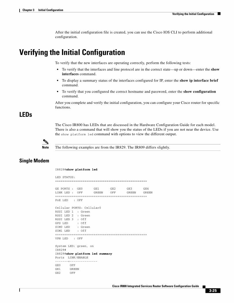
LEDsThe Cisco IR800 has LEDs that are discussed in the Hardware Configuration Guide for each model. There is also a command that will show you the status of the LEDs if you are not near the device. Use the show platform led command with options to view the different output.
Note The following examples are from the IR829. The IR809 differs slightly.
Single Modem
IR829#show platform led
LED STATUS:==================================================
GE PORTS : GE0 GE1 GE2 GE3 GE4LINK LED : OFF GREEN OFF GREEN GREEN==================================================PoE LED : OFF
Cellular PORTS: Cellular0RSSI LED 1 : GreenRSSI LED 2 : GreenRSSI LED 3 : OffGPS LED : OffSIM0 LED : GreenSIM1 LED : Off==================================================VPN LED : OFF
System LED: green, onIR829#IR829#show platform led summaryPorts LINK/ENABLE-------+---------------GE0 OFFGE1 GREENGE2 OFF
3-25Cisco IR800 Integrated Services Router Software Configuration Guide

Chapter 3 Initial Configuration Verifying the Initial Configuration
GE3 GREENGE4 GREEN-------+---------------PoE LED : OFF
RSSI 1 RSSI 2 RSSI 3 GPS-----+------------+------------+------------+-------------Ce0 Green Green Off Off
-----+------------+------------+------------+-------------
Cellular SIM0 SIM1--------+-------+-------Ce0 Green Off--------+-------+-------VPN LED : OFF
System LED: green, onIR829#IR829#show platform led systemSystem LED: green, onSummary of the LED status providers: Client Type Status------------------------------ -------- --------GigabitEthernet0 critical OKGigabitEthernet1 critical OKGigabitEthernet3 critical OKGigabitEthernet4 critical OKCellular0 critical OK--------------------------------------------------
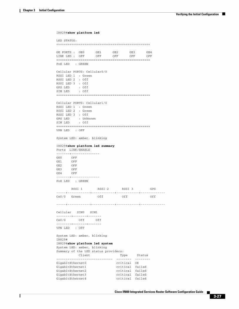
Dual Modem
IR829#show platform led
LED STATUS:==================================================
GE PORTS : GE0 GE1 GE2 GE3 GE4LINK LED : OFF OFF OFF OFF OFF==================================================PoE LED : GREEN
Cellular PORTS: Cellular0/0RSSI LED 1 : GreenRSSI LED 2 : OffRSSI LED 3 : OffGPS LED : OffSIM LED : Off==================================================
Cellular PORTS: Cellular1/0RSSI LED 1 : GreenRSSI LED 2 : GreenRSSI LED 3 : OffGPS LED : UnknownSIM LED : Off==================================================VPN LED : OFF
System LED: amber, blinking
3-26Cisco IR800 Integrated Services Router Software Configuration Guide
Chapter 3 Initial Configuration Verifying the Initial Configuration
IR829#show platform led
LED STATUS:==================================================
GE PORTS : GE0 GE1 GE2 GE3 GE4LINK LED : OFF OFF OFF OFF OFF==================================================PoE LED : GREEN
Cellular PORTS: Cellular0/0RSSI LED 1 : GreenRSSI LED 2 : OffRSSI LED 3 : OffGPS LED : OffSIM LED : Off==================================================
Cellular PORTS: Cellular1/0RSSI LED 1 : GreenRSSI LED 2 : GreenRSSI LED 3 : OffGPS LED : UnknownSIM LED : Off==================================================VPN LED : OFF
System LED: amber, blinking
IR829#show platform led summaryPorts LINK/ENABLE-------+---------------GE0 OFFGE1 OFFGE2 OFFGE3 OFFGE4 OFF-------+---------------PoE LED : GREEN
RSSI 1 RSSI 2 RSSI 3 GPS-----+------------+------------+------------+-------------Ce0/0 Green Off Off Off
-----+------------+------------+------------+-------------
Cellular SIM0 SIM1--------+-------+-------Ce0/0 Off Off--------+-------+-------VPN LED : OFF
System LED: amber, blinkingIR829#IR829#show platform led systemSystem LED: amber, blinkingSummary of the LED status providers: Client Type Status------------------------------ -------- --------GigabitEthernet0 critical OKGigabitEthernet1 critical failedGigabitEthernet2 critical failedGigabitEthernet3 critical failedGigabitEthernet4 critical failed
3-27Cisco IR800 Integrated Services Router Software Configuration Guide
Chapter 3 Initial Configuration Verifying the Initial Configuration
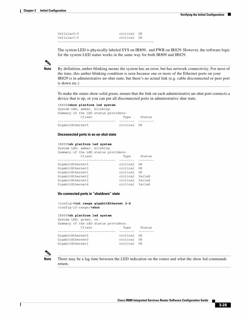
Cellular0/0 critical OKCellular1/0 critical OK--------------------------------------------------
The system LED is physically labeled SYS on IR809, and PWR on IR829. However, the software logic for the system LED status works in the same way for both IR809 and IR829.
Note By definition, amber blinking means the system has an error, but has network connectivity. For most of the time, this amber blinking condition is seen because one or more of the Ethernet ports on your IR829 is in administrative un-shut state, but there’s no actual link (e.g. cable disconnected or peer port is down etc.)
To make the status show solid green, ensure that the link on each administrative un-shut port connects a device that is up, or you can put all disconnected ports in administrative shut state.
IR800#show platform led system System LED: amber, blinkingSummary of the LED status providers: Client Type Status------------------------------ -------- --------GigabitEthernet5 critical OK
Unconnected ports in an un-shut state
IR800#sh platform led system System LED: amber, blinkingSummary of the LED status providers: Client Type Status------------------------------ -------- --------GigabitEthernet5 critical OK GigabitEthernet0 critical OK GigabitEthernet1 critical OK GigabitEthernet2 critical failed GigabitEthernet3 critical failed GigabitEthernet4 critical failed
Un-connected ports in “shutdown” state
(config)#int range gigabitEthernet 2-4(config-if-range)#shut
IR800#sh platform led system System LED: green, onSummary of the LED status providers: Client Type Status------------------------------ -------- --------GigabitEthernet5 critical OK GigabitEthernet0 critical OK GigabitEthernet1 critical OK
Note There may be a lag time between the LED indication on the router and what the show led commands return.
3-28Cisco IR800 Integrated Services Router Software Configuration Guide
Chapter 3 Initial Configuration Verifying the Initial Configuration
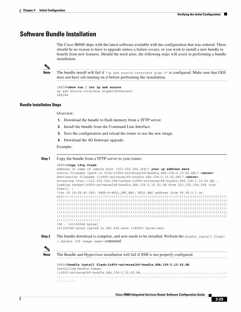
Software Bundle InstallationThe Cisco IR800 ships with the latest software available with the configuration that was ordered. There should be no reason to have to upgrade unless a failure occurs, or you wish to install a new bundle to benefit from new features. Should the need arise, the following steps will assist in performing a bundle installation.
Note The bundle install will fail if “ip ssh source-interface gige 0” is configured. Make sure that GE0 does not have ssh running on it before performing the installation.
IR829#show run | inc ip ssh sourceip ssh source-interface GigabitEthernet0IR829#
Bundle Installation Steps
Overview:
1. Download the bundle to flash memory from a TFTP server.
2. Install the bundle from the Command Line Interface
3. Save the configuration and reload the router to use the new image.
4. Download the 4G firmware upgrade.
Example:
Step 1 Copy the bundle from a TFTP server to your router.
IR800#copy tftp flash Address or name of remote host [223.255.254.254]? your ip address hereSource filename [path to file/ir800-universalk9-bundle.SSA.156-2.10.62.GB]? <enter>Destination filename [ir800-universalk9-bundle.SSA.156-2.10.62.GB]? <enter>Accessing tftp://223.255.254.254/tachen/ir800-universalk9-bundle.SSA.156-2.10.62.GB...Loading tachen/ir800-universalk9-bundle.SSA.156-2.10.62.GB from 223.255.254.254 (via Vlan1): !*Jun 25 18:28:45.685: %ARP-4-NULL_SRC_MAC: NULL MAC address from 99.99.0.1 on wl0!!!!!!!!!!!!!!!!!!!!!!!!!!!!!!!!!!!!!!!!!!!!!!!!!!!!!!!!!!!!!!!!!!!!!!!!!!!!!!!!!!!!!!!!!!!!!!!!!!!!!!!!!!!!!!!!!!!!!!!!!!!!!!!!!!!!!!!!!!!!!!!!!!!!!!!!!!!!!!!!!!!!!!!!!!!!!!!!!!!!!!!!!!!!!!!!!!!!!!!!!!!!!!!!!!!!!!!!!!!!!!!!!!!!!!!!!!!!!!!!!!!!!!!!!!!!!!!!!!!!!!!!!!!!!!!!!!!!!!!!!!!!!!!!!!!!!!!!!!!!!!!!!!!!!!!!!!!!!!!!!!!!!!!!!!!!!!!!!!!!!!!!!!!!!!!!!!!!!!!!!!!!!!!!!!!!!!!!!!!!!!!!!!!!!!!!!!!!!!!!!!!!!!!!!!!!!!!!!!!!!!!!!!!!!!!!!!!!!!!!!!!!!!!!!!!!!!!!!!!!!!!!!!!!!!!!!!!!!!!!!!!!!!!!!!!!!!!!!!!!!!!!!!!!!!!!!!!!!!!!!!!!!!!!!!!!!!!!!!!!!!!!!!!!!!!!!!!!!!!![OK - 161162048 bytes]161162048 bytes copied in 466.054 secs (345801 bytes/sec)
Step 2 The bundle download is complete, and now needs to be installed. Perform the bundle install flash: < bundle iOS image name> command.
Note The Bundle and Hypervisor installation will fail if SSH is not properly configured.
IR800#bundle install flash:ir800-universalk9-bundle.SSA.156-2.10.62.GBInstalling bundle image: /ir800-universalk9-bundle.SSA.156-2.10.62.GB..................................................................................................................................................
3-29Cisco IR800 Integrated Services Router Software Configuration Guide

Chapter 3 Initial Configuration Verifying the Initial Configuration
updating Hypervisor image...Sending file modes: C0444 25160429 ir800-hv.srp.SPA.2.6.9
SRP md5 verification passed!
updating IOS image...Sending file modes: C0644 63827874 ir800-universalk9-mz.SSA.156-2.10.62.GB
IOS md5 verification passed!Done!
IR800#*Nov 16 18:54:39.456: %SYS-5-CONFIG_I: Configured from console by bundle install command*Nov 16 18:54:39.456: %IR800_INSTALL-6-SUCCESS_BUNDLE_INSTALL: Successfully installed bundle image.
Step 3 (Optional) View which version of hypervisor you are running.
IR800# show platform hypervisorversion: 2.5.5.2
Step 4 Verify the boot system parameter before reloading the router.
Step 5 Save the configuration and reload the router.
IR800#reload
Do you want to reload the internal AP ? [yes/no]: yes
System configuration has been modified. Save? [yes/no]: yesBuilding configuration...
[OK]Proceed with reload? [confirm] <enter>
*Jun 25 19:03:13.685: %SYS-5-RELOAD: Reload requested by console. Reload Reason: Reload Command.
Step 6 Download the 4G firmware or AP image. Instructions for uploading firmware are located here:
http://www.cisco.com/c/en/us/td/docs/routers/access/interfaces/software/feature/guide/EHWIC-4G-LTESW.html
Search for “Upgrading the Modem Firmware”.
Power Over Ethernet (PoE)The IR829 has an optional PoE accessory (IR800-IL-POE). When installed, it supplies a maximum of 30.8W shared between the 4 GE LAN ports (GI1-GI4). The Power can be distributed among the ports in the following manner:
• If one port supports PoE+ (30W), then the other ports have no PoE.
• If 2 ports support PoE (15.4 W), then the other ports have no PoE
• All 4 ports can support 7.7 W per port
Note The router can not be upgraded for PoE in the field.
3-30Cisco IR800 Integrated Services Router Software Configuration Guide
Chapter 3 Initial Configuration Where To Go From Here
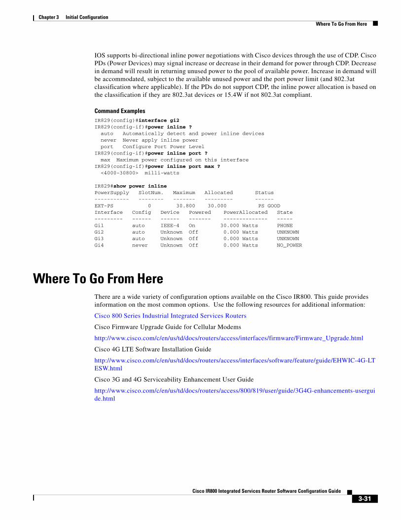
IOS supports bi-directional inline power negotiations with Cisco devices through the use of CDP. Cisco PDs (Power Devices) may signal increase or decrease in their demand for power through CDP. Decrease in demand will result in returning unused power to the pool of available power. Increase in demand will be accommodated, subject to the available unused power and the port power limit (and 802.3at classification where applicable). If the PDs do not support CDP, the inline power allocation is based on the classification if they are 802.3at devices or 15.4W if not 802.3at compliant.
Command ExamplesIR829(config)#interface gi2IR829(config-if)#power inline ? auto Automatically detect and power inline devices never Never apply inline power port Configure Port Power LevelIR829(config-if)#power inline port ? max Maximum power configured on this interfaceIR829(config-if)#power inline port max ? <4000-30800> milli-watts
IR829#show power inline PowerSupply SlotNum. Maximum Allocated Status----------- -------- ------- --------- ------EXT-PS 0 30.800 30.000 PS GOODInterface Config Device Powered PowerAllocated State --------- ------ ------ ------- -------------- ----- Gi1 auto IEEE-4 On 30.000 Watts PHONE Gi2 auto Unknown Off 0.000 Watts UNKNOWN Gi3 auto Unknown Off 0.000 Watts UNKNOWN Gi4 never Unknown Off 0.000 Watts NO_POWER
Where To Go From HereThere are a wide variety of configuration options available on the Cisco IR800. This guide provides information on the most common options. Use the following resources for additional information:
Cisco 800 Series Industrial Integrated Services Routers
Cisco Firmware Upgrade Guide for Cellular Modems
http://www.cisco.com/c/en/us/td/docs/routers/access/interfaces/firmware/Firmware_Upgrade.html
Cisco 4G LTE Software Installation Guide
http://www.cisco.com/c/en/us/td/docs/routers/access/interfaces/software/feature/guide/EHWIC-4G-LTESW.html
Cisco 3G and 4G Serviceability Enhancement User Guide
http://www.cisco.com/c/en/us/td/docs/routers/access/800/819/user/guide/3G4G-enhancements-userguide.html
3-31Cisco IR800 Integrated Services Router Software Configuration Guide

Cisco IR800 Integr
C H A P T E R 4
Cellular Interface ModulesThis chapter provides configuration details for the cellular interface modules used in the IR800 series routers.
This chapter contains the following sections:
• Cellular Interface, page 4-33
– 4G LTE Dual SIMs, page 4-33
– Dual Radio Configuration and Single Radio Configuration, page 4-34
– Other Useful Commands, page 4-42
• IR800 Cellular Technology Selection, page 4-44
• GPS, page 4-47
• Troubleshooting the Cellular Interface, page 4-48
It is important to understand the architecture of the IR800 series and the relationship between Modems, SIMs, Interface and Controller. The following table helps to illustrate these relationships.
Note * As of Release 15.5(3)M2, the only dual-modem scenario supported is two MC7455 modems.
With the introduction of the next generation SKUs, some functionality has changed. Refer to the following table for details.
Router Controller SIM Modem Slot PDN Interface Line
IR829 0 0|1 0 Cellular 0 3
IR829 0 0|1 0 Cellular 1 8
IR829 (dual modem) * 0 0 0 Cellular 0/0 3
IR829 (dual modem) * 0 0 0 Cellular 0/1 8
IR829 (dual modem) * 1 1 1 Cellular 1/0 9
IR829 (dual modem) * 1 1 1 Cellular 1/1 15
IR809 0 0|1 0 Cellular 0 3
IR809 0 0|1 0 Cellular 1 8
4-32ated Services Router Software Configuration Guide

Chapter 4 Cellular Interface Modules Cellular Interface
Cellular InterfaceThe Cisco IR800 series Industrial routers use the Sierra Wireless MC73XX and MC74XX series modems supporting MIMO on LTE. WCDMA UMTS HSPA DC-HSPA+ is diversity only, without MIMO.
Installation of the SIM card(s) and antennas is covered in the respective Hardware Installation Guides under the Cisco 800 Series Industrial Integrated Services Routers page:
http://www.cisco.com/c/en/us/support/routers/800-series-industrial-routers/tsd-products-support-series-home.html
The software download page can be found here:
https://software.cisco.com/download/navigator.html?mdfid=286288566&flowid=76082
The Firmware Upgrade Guide for Cellular Modems can be found here:
http://www.cisco.com/c/en/us/td/docs/routers/access/interfaces/firmware/Firmware_Upgrade.html
Cisco 4G LTE Software Installation Guide
http://www.cisco.com/c/en/us/td/docs/routers/access/interfaces/software/feature/guide/EHWIC-4G-LTESW.html
After installing the SIM card(s) and antennas, check the cellular hardware, radio, network and SIM (Unlock SIM card if necessary).
4G LTE Dual SIMsThe Dual SIMs feature provides the following:
Description IR829GW-[LA/GA/NA/VZ]-*K9 IR829-2LTE-EA-*K9
North American Yes Yes
APJC Yes No
EMER Yes Yes
EMEA Yes Yes
2G Support Yes No
3G Support Yes Yes
LTE Support Yes Yes
GPS Yes Yes
Wi-Fi (2.4/5 GHZ) 2.4 GHz and 5GHz use separate antenna connector
2.4 GHz + 5GHz coexist on the same antenna connector
Dual SIM Yes No
Band 30 No No
LTE category supported cat4 cat4
4-33Cisco IR800 Integrated Services Router Software Configuration Guide
Chapter 4 Cellular Interface Modules Cellular Interface
• A fail over mechanism in the event the primary SIM looses connectivity to one of the Mobile Service Provider networks. There is no automatic fall-back to the primary SIM, since a change only occurs when there is no signal from the carrier in use. A script is needed to reverse back to the primary. Both mobile provider networks must be supported by the given IR829 SKU, and it must be in an applicable region.
– By default, SIM slot 0 is the primary, and SIM slot1 is the backup. Behavior may be changed using the lte sim primary command.
– Profiles for each SIM are assigned by using the lte sim profile command. Each SIM has an associated Internet profile and an IMS profile in the CLI.
– Dual-SIM behavior is managed under Cellular 0 CLI configuration.
– The fail-overs happen when there is no signal from the current carrier, and generally happen depending on the fail-over timer value that is set. The default value is 2 minutes. The range is from 0-7 minutes.
• Dual active LTE radios providing Multi-carrier support for active and backup use cases. Newer cellular modems have been added (MC74xx) with FDD/TDD LTE on LA and EA 829 models.
– New WiFi domains for APAC and LATAM
Note The 7455 modems do not support dual simm capabilities.
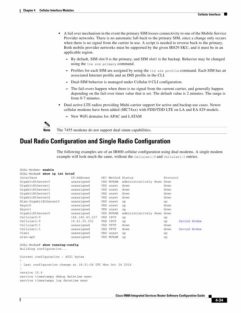
Dual Radio Configuration and Single Radio ConfigurationThe following examples are of an IR800 cellular configuration using dual modems. A single modem example will look much the same, without the Cellular1/0 and Cellular1/1 entries.
DUAL-Modem> enableDUAL-Modem# show ip int briefInterface IP-Address OK? Method Status ProtocolGigabitEthernet0 unassigned YES NVRAM administratively down down GigabitEthernet1 unassigned YES unset down down GigabitEthernet2 unassigned YES unset down down GigabitEthernet3 unassigned YES unset down down GigabitEthernet4 unassigned YES unset down down Wlan-GigabitEthernet0 unassigned YES unset up up Async0 unassigned YES unset up down Async1 unassigned YES unset up down GigabitEthernet5 unassigned YES NVRAM administratively down down Cellular0/0 166.140.43.237 YES IPCP up up Cellular1/0 10.61.25.231 YES IPCP up up Second ModemCellular0/1 unassigned YES TFTP down down Cellular1/1 unassigned YES TFTP down down Second ModemVlan1 unassigned YES unset up up wlan-ap0 unassigned YES NVRAM up up
DUAL-Modem# show running-config Building configuration...
Current configuration : 4021 bytes!! Last configuration change at 18:31:06 UTC Mon Oct 24 2016!version 15.6service timestamps debug datetime msecservice timestamps log datetime msec
4-34Cisco IR800 Integrated Services Router Software Configuration Guide
Chapter 4 Cellular Interface Modules Cellular Interface
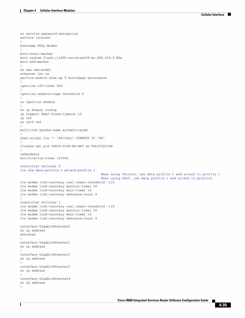
no service password-encryptionservice internal!hostname DUAL-Modem!boot-start-markerboot system flash:/ir800-universalk9-mz.SPA.156-3.M0aboot-end-marker!no aaa new-modelethernet lmi ceservice-module wlan-ap 0 bootimage autonomous!ignition off-timer 900!ignition undervoltage threshold 9!no ignition enable!no ip domain lookupip inspect WAAS flush-timeout 10ip cefno ipv6 cef!multilink bundle-name authenticated!chat-script lte "" "AT!CALL" TIMEOUT 20 "OK"!license udi pid IR829-2LTE-EA-BK9 sn FGL2032219N!redundancynotification-timer 120000
controller Cellular 0lte sim data-profile 3 attach-profile 1 When using Verizon, use data profile 3 and attach to profile 1 When using AT&T, use data profile 1 and attach to profile1lte modem link-recovery rssi onset-threshold -110lte modem link-recovery monitor-timer 20lte modem link-recovery wait-timer 10lte modem link-recovery debounce-count 6!controller Cellular 1lte modem link-recovery rssi onset-threshold -110lte modem link-recovery monitor-timer 20lte modem link-recovery wait-timer 10lte modem link-recovery debounce-count 6
interface GigabitEthernet0no ip addressshutdown!interface GigabitEthernet1no ip address!interface GigabitEthernet2no ip address!interface GigabitEthernet3no ip address!interface GigabitEthernet4no ip address!
4-35Cisco IR800 Integrated Services Router Software Configuration Guide

Chapter 4 Cellular Interface Modules Cellular Interface
interface Wlan-GigabitEthernet0no ip address!interface GigabitEthernet5no ip addressshutdownduplex autospeed auto!interface Cellular0/0 Both interfaces need to be configured in the IOS softwareip address negotiatedip virtual-reassembly inencapsulation slipload-interval 30dialer in-banddialer string ltedialer-group 1no peer default ip addressasync mode interactiverouting dynamic!interface Cellular1/0 Both interfaces need to be configured in the IOS softwareip address negotiatedip virtual-reassembly inencapsulation slipload-interval 30dialer in-banddialer string ltedialer-group 1no peer default ip addressasync mode interactiverouting dynamic!interface Cellular0/1no ip addressencapsulation slip!interface Cellular1/1no ip addressencapsulation slip!interface wlan-ap0no ip address!interface Vlan1no ip address!interface Async0no ip addressencapsulation scada!interface Async1no ip addressencapsulation scada!!ip forward-protocol nd!no ip http serverno ip http secure-server!ip route 0.0.0.0 0.0.0.0 Cellular1/0ip route 8.8.8.8 255.255.255.255 Cellular0/0 Route values added!
4-36Cisco IR800 Integrated Services Router Software Configuration Guide

Chapter 4 Cellular Interface Modules Cellular Interface
dialer-list 1 protocol ip permitipv6 ioam timestamp!access-list 1 permit any!control-plane!!line con 0stopbits 1line 1 2stopbits 1line 3script dialer lteno exectransport preferred lat pad telnet rlogin lapb-ta mop udptn v120 sshtransport output lat pad telnet rlogin lapb-ta mop udptn v120 sshrxspeed 150000000txspeed 50000000line 4no activation-characterno exectransport preferred nonetransport input alltransport output lat pad telnet rlogin lapb-ta mop udptn v120 sshline 8script dialer lteno exectransport preferred lat pad telnet rlogin lapb-ta mop udptn v120 sshtransport output lat pad telnet rlogin lapb-ta mop udptn v120 sshrxspeed 150000000txspeed 50000000line 9script dialer lteno exectransport preferred lat pad telnet rlogin lapb-ta mop udptn v120 sshtransport input alltransport output lat pad telnet rlogin lapb-ta mop udptn v120 sshrxspeed 236800txspeed 118000line 15no exectransport preferred lat pad telnet rlogin lapb-ta mop udptn v120 sshtransport output lat pad telnet rlogin lapb-ta mop udptn v120 sshrxspeed 236800txspeed 118000line 1/3 1/6transport preferred nonetransport output nonestopbits 1line vty 0 4logintransport input none!no scheduler max-task-time!!End
Test the modem configuration with a ping command:
DUAL-Modem# ping 8.8.8.8Type escape sequence to abort.Sending 5, 100-byte ICMP Echos to 8.8.8.8, timeout is 2 seconds:!!!!!
4-37Cisco IR800 Integrated Services Router Software Configuration Guide

Chapter 4 Cellular Interface Modules Cellular Interface
Success rate is 100 percent (5/5), round-trip min/avg/max = 30/88/292 msDUAL-Modem#
The following two examples show a Verizon profile followed by an AT&T profile.
Verizon Profile
DUAL-Modem# show cellular 0/0 profile
Profile 1 = INACTIVE **--------PDP Type = IPv4v6Access Point Name (APN) = vzwimsAuthentication = None
Profile 2 = INACTIVE--------PDP Type = IPv4v6Access Point Name (APN) = vzwadminAuthentication = None
Profile 3 = ACTIVE* Profile 3 is used for Verizon--------PDP Type = IPv4v6PDP address = 166.140.43.237Access Point Name (APN) = we01.VZWSTATICAuthentication = None Primary DNS address = 198.224.173.135 Secondary DNS address = 198.224.174.135
Profile 4 = INACTIVE-------- PDP Type = IPv4v6Access Point Name (APN) = vzwappAuthentication = None
Profile 5 = INACTIVE--------PDP Type = IPv4v6Access Point Name (APN) = vzw800Authentication = None
Profile 6 = INACTIVE--------PDP Type = IPv4v6Access Point Name (APN) = vzwenterpriseAuthentication = None
* - Default profile ** - LTE attach profile
AT&T Profile
DUAL-Modem# show cellular 1/0 profile
Profile 1 = ACTIVE* ** Profile 1 is used for AT&T--------PDP Type = IPv4PDP address = 10.61.25.231Access Point Name (APN) = m2m.com.attz
4-38Cisco IR800 Integrated Services Router Software Configuration Guide

Chapter 4 Cellular Interface Modules Cellular Interface
Authentication = None Primary DNS address = 8.8.8.8 Secondary DNS address = 8.8.4.4
* - Default profile ** - LTE attach profile
DUAL-Modem# show cellular 0/0 hardware Modem Firmware Version = SWI9X30C_02.20.03.00Modem Firmware built = 2016/06/30 10:54:05Hardware Version = 1.0Device Model ID: MC7455MOBILEInternational Mobile Subscriber Identity (IMSI) = 311480166946902International Mobile Equipment Identity (IMEI) = 352009080050110Integrated Circuit Card ID (ICCID) = 89148000001653263375Mobile Subscriber Integrated ServicesDigital Network-Number (MSISDN) = 6692200807Modem Status = OnlineCurrent Modem Temperature = 34 deg CPRI SKU ID = 1103084, PRI version = 002.024, Carrier = Verizon Carrier identified as VerizonOEM PRI version = 000.001
Creating a Cellular Profile for Verizon.
DUAL-Modem# cellular 0/0 lte profile create 3 we01.VZWSTATICWarning: You are attempting to modify a currently ACTIVE data profile. This is not recommended and may affect the connection state
PDP Type = IPv4v6Access Point Name (APN) = we01.VZWSTATICAuthentication = NONE
Profile 3 already exists with above parameters. Do you want to overwrite? [confirm] <return>
Profile 3 will be overwritten with the following values:
PDP type = IPv4APN = we01.VZWSTATICAuthentication = NONE
Are you sure? [confirm] <return>Profile 3 written to modem
DUAL-Modem#
Enter configuration commands, one per line. End with CNTL/Z.DUAL-Modem(config)# controller cellular 0DUAL-Modem(config-controller)# lte sim data-profile 3 attach-profile 1DUAL-Modem(config-controller)#
DUAL-Modem# conf tEnter configuration commands, one per line. End with CNTL/Z.DUAL-Modem(config)# controller cellular 0DUAL-Modem(config-controller)# lte sim data-profile 3 attach-profile 1
DUAL-Modem(config-controller)# end
4-39Cisco IR800 Integrated Services Router Software Configuration Guide
Chapter 4 Cellular Interface Modules Cellular Interface
DUAL-Modem#
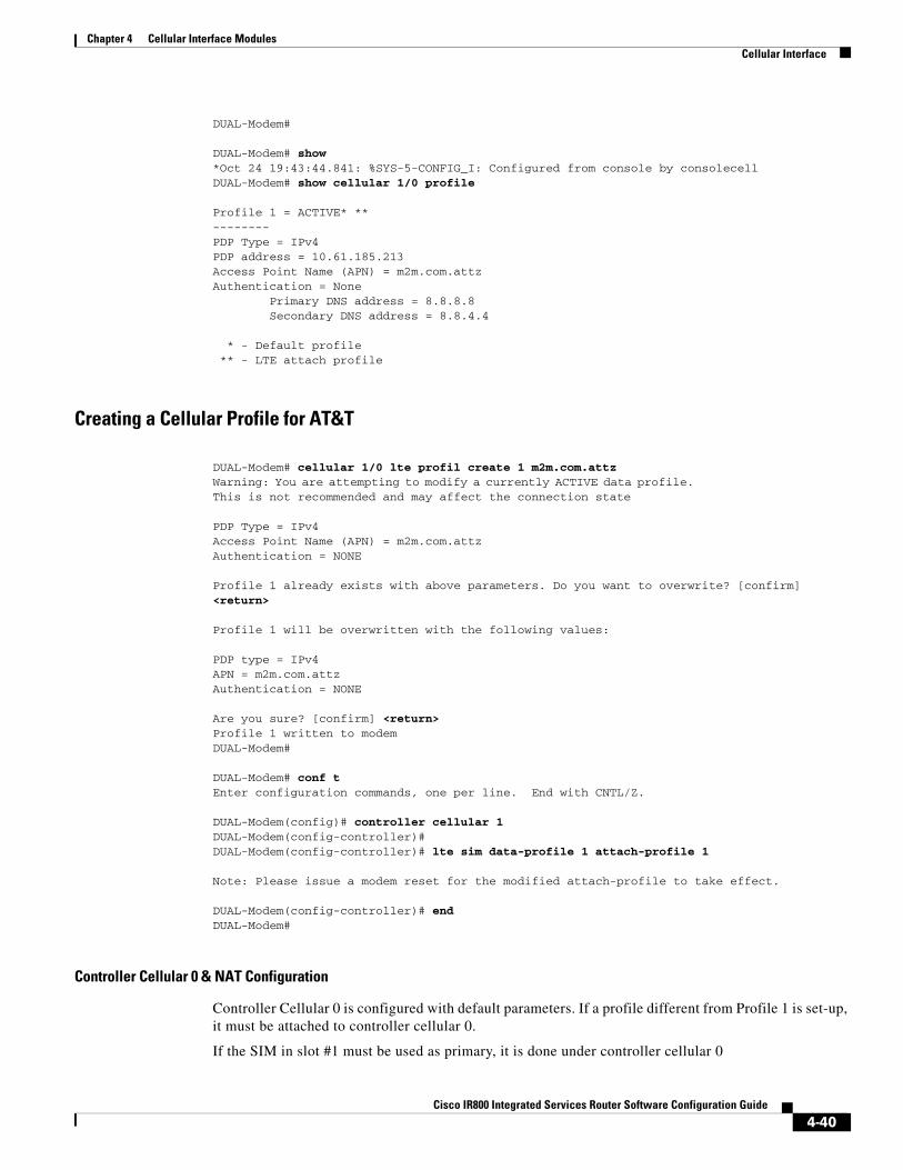
DUAL-Modem# show *Oct 24 19:43:44.841: %SYS-5-CONFIG_I: Configured from console by consolecellDUAL-Modem# show cellular 1/0 profile
Profile 1 = ACTIVE* **--------PDP Type = IPv4PDP address = 10.61.185.213Access Point Name (APN) = m2m.com.attzAuthentication = None Primary DNS address = 8.8.8.8 Secondary DNS address = 8.8.4.4
* - Default profile ** - LTE attach profile
Creating a Cellular Profile for AT&T
DUAL-Modem# cellular 1/0 lte profil create 1 m2m.com.attzWarning: You are attempting to modify a currently ACTIVE data profile. This is not recommended and may affect the connection state
PDP Type = IPv4Access Point Name (APN) = m2m.com.attzAuthentication = NONE
Profile 1 already exists with above parameters. Do you want to overwrite? [confirm] <return>
Profile 1 will be overwritten with the following values:
PDP type = IPv4APN = m2m.com.attzAuthentication = NONE
Are you sure? [confirm] <return>Profile 1 written to modemDUAL-Modem#
DUAL-Modem# conf tEnter configuration commands, one per line. End with CNTL/Z.
DUAL-Modem(config)# controller cellular 1DUAL-Modem(config-controller)#DUAL-Modem(config-controller)# lte sim data-profile 1 attach-profile 1
Note: Please issue a modem reset for the modified attach-profile to take effect.
DUAL-Modem(config-controller)# endDUAL-Modem#
Controller Cellular 0 & NAT Configuration
Controller Cellular 0 is configured with default parameters. If a profile different from Profile 1 is set-up, it must be attached to controller cellular 0.
If the SIM in slot #1 must be used as primary, it is done under controller cellular 0
4-40Cisco IR800 Integrated Services Router Software Configuration Guide

Chapter 4 Cellular Interface Modules Cellular Interface
Step 1 Show the controller cellular 0
IR800#show run | begin controllercontroller Cellular 0 lte sim data-profile 1 attach-profile 1 slot 0! Value set-up for configuration example lte sim max-retry 0 lte failovertimer 0 lte modem link-recovery rssi onset-threshold -110 lte modem link-recovery monitor-timer 20 lte modem link-recovery wait-timer 10 lte modem link-recovery debounce-count 6!
Step 2 If the cellular interface obtains an IPv4 private address, NAT should be configured.
IR800#conf termEnter configuration commands, one per line. End with CNTL/Z.IR800(config)#inter cellular 0IR800(config-if)#ip nat outsideIR800(config)#inter vlan 4IR800(config-if)#ip nat insideIR800(config)#access-list 10 permit 10.20.20.0 0.0.0.255! IPv4 subnet to be NATedIR800(config)# ip nat inside source list 10 interface Cellular0 overload!NAT interface association
Step 3 Once the Cellular configuration is done, ping a well-known IP address to test the connectivity.
IR800#ping 8.8.8.8 Type escape sequence to abort.Sending 5, 100-byte ICMP Echos to 8.8.8.8, timeout is 2 seconds:!!!!!Success rate is 100 percent (5/5), round-trip min/avg/max = 340/472/740 msIR800#
Step 4 Attached Cellular 0 profile must become “active” and “connection” shows IP address and traffic.
IR800#show cellular 0 profile Profile 1 = ACTIVE* **--------PDP Type = IPv4PDP address = 10.60.159.255Access Point Name (APN) = LTEAuthentication = None
Primary DNS address = 212.27.40.240Secondary DNS address = 212.27.40.241
* - Default profile ** - LTE attach profileConfigured default profile for active SIM 0 is profile 1.
IR800#show cellular 0 connection Profile 1, Packet Session Status = ACTIVE
Cellular0:Data Transmitted = 700 bytes, Received = 600 bytesIP address = 10.60.159.255Primary DNS address = 212.27.40.240Secondary DNS address = 212.27.40.241
Profile 2, Packet Session Status = INACTIVE
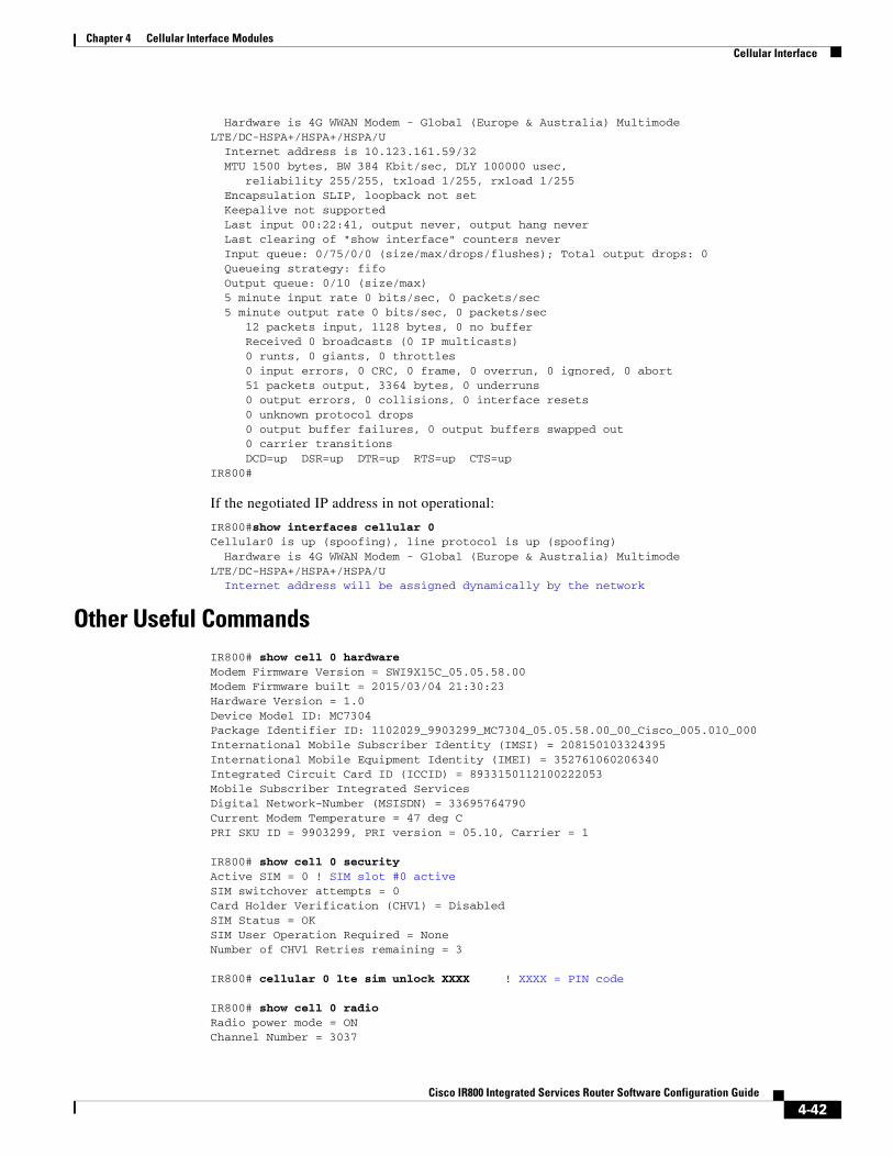
Use the show interface cellular 0 command to display the negotiated IP address if operational.
IR800#show interfaces cellular 0Cellular0 is up, line protocol is up
4-41Cisco IR800 Integrated Services Router Software Configuration Guide
Chapter 4 Cellular Interface Modules Cellular Interface
Hardware is 4G WWAN Modem - Global (Europe & Australia) Multimode LTE/DC-HSPA+/HSPA+/HSPA/U Internet address is 10.123.161.59/32 MTU 1500 bytes, BW 384 Kbit/sec, DLY 100000 usec, reliability 255/255, txload 1/255, rxload 1/255 Encapsulation SLIP, loopback not set Keepalive not supported Last input 00:22:41, output never, output hang never Last clearing of "show interface" counters never Input queue: 0/75/0/0 (size/max/drops/flushes); Total output drops: 0 Queueing strategy: fifo Output queue: 0/10 (size/max) 5 minute input rate 0 bits/sec, 0 packets/sec 5 minute output rate 0 bits/sec, 0 packets/sec 12 packets input, 1128 bytes, 0 no buffer Received 0 broadcasts (0 IP multicasts) 0 runts, 0 giants, 0 throttles 0 input errors, 0 CRC, 0 frame, 0 overrun, 0 ignored, 0 abort 51 packets output, 3364 bytes, 0 underruns 0 output errors, 0 collisions, 0 interface resets 0 unknown protocol drops 0 output buffer failures, 0 output buffers swapped out 0 carrier transitions DCD=up DSR=up DTR=up RTS=up CTS=upIR800#
If the negotiated IP address in not operational:
IR800#show interfaces cellular 0Cellular0 is up (spoofing), line protocol is up (spoofing) Hardware is 4G WWAN Modem - Global (Europe & Australia) Multimode LTE/DC-HSPA+/HSPA+/HSPA/U Internet address will be assigned dynamically by the network
Other Useful CommandsIR800# show cell 0 hardware Modem Firmware Version = SWI9X15C_05.05.58.00Modem Firmware built = 2015/03/04 21:30:23Hardware Version = 1.0Device Model ID: MC7304Package Identifier ID: 1102029_9903299_MC7304_05.05.58.00_00_Cisco_005.010_000International Mobile Subscriber Identity (IMSI) = 208150103324395International Mobile Equipment Identity (IMEI) = 352761060206340Integrated Circuit Card ID (ICCID) = 8933150112100222053Mobile Subscriber Integrated ServicesDigital Network-Number (MSISDN) = 33695764790Current Modem Temperature = 47 deg CPRI SKU ID = 9903299, PRI version = 05.10, Carrier = 1
IR800# show cell 0 security Active SIM = 0 ! SIM slot #0 activeSIM switchover attempts = 0Card Holder Verification (CHV1) = DisabledSIM Status = OKSIM User Operation Required = NoneNumber of CHV1 Retries remaining = 3
IR800# cellular 0 lte sim unlock XXXX ! XXXX = PIN code
IR800# show cell 0 radio Radio power mode = ONChannel Number = 3037
4-42Cisco IR800 Integrated Services Router Software Configuration Guide

Chapter 4 Cellular Interface Modules Cellular Interface
Current Band = UnknownCurrent RSSI(RSCP) = -99 dBmCurrent ECIO = -10 dBmRadio Access Technology(RAT) Preference = AUTORadio Access Technology(RAT) Selected = UMTS ( UMTS/WCDMA )
IR800# show cell 0 network Current System Time = Sat Oct 10 9:12:59 2015Current Service Status = NormalCurrent Service = Packet switchedCurrent Roaming Status = HomeNetwork Selection Mode = AutomaticNetwork = LTEMobile Country Code (MCC) = 208Mobile Network Code (MNC) = 15Packet switch domain(PS) state = AttachedLocation Area Code (LAC) = 3910Cell ID = 222094374
IR800# show cell 0 all
Note The output to the show cell 0 all command is extensive, and omitted from this guide for brevity.
Accessing 4G Modem AT Commands
Note A password must be added to the line configuration for security.
Get the line number associated to Cellular 0:
IR800#show line Tty Line Typ Tx/Rx A Modem Roty AccO AccI Uses Noise Overruns In I 3 3 TTY - - - - - 1 0 4/0 Ce0
Use one of the IR800 IP address along with 2000 + line number (2003)
IR800#10.15.15.1 2003Trying 10.15.15.1, 2003 ... Open
Execute the 4G modem AT commands, for example AT!GSTATUS?:
AT!GSTATUS?!GSTATUS: Current Time: 213353Temperature: 38Bootup Time: 0Mode: ONLINE System mode: WCDMA PS state: Attached WCDMA band: WCDMA 900 WCDMA channel: 3037GMM (PS) state:REGISTERED NORMAL SERVICE MM (CS) state: IDLE NORMAL SERVICE WCDMA L1 state:L1M_PCH_SLEEP LAC: 0F46 (3910)RRC state: DISCONNECTED Cell ID: 0D3CE428 (222094376)RxM RSSI C0: -90RxD RSSI C0: -106RxM RSSI C1: -106RxD RSSI C1: -106
Disconnect using “SHIFT+CONTROL+6+x”, then confirm:
IR800#discClosing connection to 1.2.2.2 [confirm]enterIR800#
4-43Cisco IR800 Integrated Services Router Software Configuration Guide

Chapter 4 Cellular Interface Modules IR800 Cellular Technology Selection
Checking 4G Modem Firmware through AT CommandsTo check the IR800 4G modem firmware, execute the 4G modem AT commands after connecting to the modem. The following example is for an IR809G-LTE-GA-K9 loaded with FW-MC7304-LTE-GB Global firmware.
Note On the IR809, the PRI SKU ID= 9903299 is not representative of the GB firmware
at!priid?PRI Part Number: 9903299Revision: 05.10Carrier PRI: 9999999_9902674_SWI9X15C_05.05.58.00_00_GENEU-4G_005.026_000OK
at!package?1102029_9903299_MC7304_05.05.58.00_00_Cisco_005.010_000
at!gobiimpref?!GOBIIMPREF: preferred fw version: 05.05.58.00 preferred carrier name: GENEU-4G preferred config name: GENEU-4G_005.026_000 current fw version: 05.05.58.00 current carrier name: GENEU-4G current config name: GENEU-4G_005.026_000
IR800 Cellular Technology SelectionThe cellular interface supports a seamless hand off between LTE and 3G networks when the LTE cell becomes weak in certain spots and vice versa. But it may also be disable to lock the cellular interface in a given technology, for example. LTE.
The Cellular interface supports 3G & 2.5G technologies. The IOS CLI can be used to select a particular technology that is most desirable in your local zone.
Use the cellular 0 lte technology command:
IR829# cellular 0 lte technology ? ! Blue values available on Global SKU auto Automatic LTE Technology Selection cdma-1xrtt CDMA 1xRTT cdma-evdo CDMA EVDO Rev A cdma-hybrid HYBRID CDMA gsm GSM lte LTE umts UMTS
Note The default technology type selection is auto and it is recommended to be used at all times. Although gsm & umts as part of the selection, the modem firmware does not support them on gsm/umts network. They will be used as lte selection on Verizon network.
Show the completed configuration: (output edited for brevity)IR800#show runBuilding configuration...
4-44Cisco IR800 Integrated Services Router Software Configuration Guide
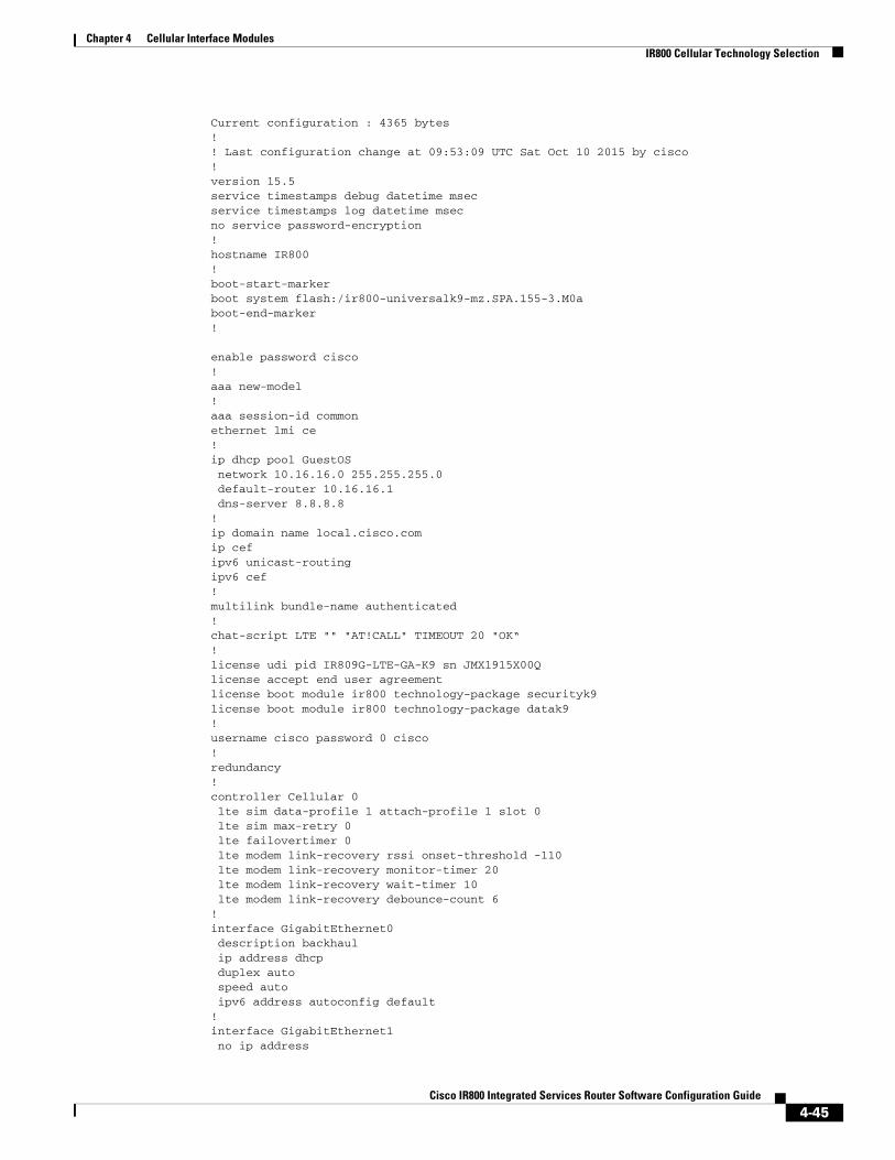
Chapter 4 Cellular Interface Modules IR800 Cellular Technology Selection
Current configuration : 4365 bytes!! Last configuration change at 09:53:09 UTC Sat Oct 10 2015 by cisco!version 15.5service timestamps debug datetime msecservice timestamps log datetime msecno service password-encryption!hostname IR800!boot-start-markerboot system flash:/ir800-universalk9-mz.SPA.155-3.M0aboot-end-marker!
enable password cisco!aaa new-model!aaa session-id commonethernet lmi ce!ip dhcp pool GuestOS network 10.16.16.0 255.255.255.0 default-router 10.16.16.1 dns-server 8.8.8.8 !ip domain name local.cisco.comip cefipv6 unicast-routingipv6 cef!multilink bundle-name authenticated!chat-script LTE "" "AT!CALL" TIMEOUT 20 "OK“!license udi pid IR809G-LTE-GA-K9 sn JMX1915X00Qlicense accept end user agreementlicense boot module ir800 technology-package securityk9license boot module ir800 technology-package datak9!username cisco password 0 cisco!redundancy!controller Cellular 0 lte sim data-profile 1 attach-profile 1 slot 0 lte sim max-retry 0 lte failovertimer 0 lte modem link-recovery rssi onset-threshold -110 lte modem link-recovery monitor-timer 20 lte modem link-recovery wait-timer 10 lte modem link-recovery debounce-count 6!interface GigabitEthernet0 description backhaul ip address dhcp duplex auto speed auto ipv6 address autoconfig default!interface GigabitEthernet1 no ip address
4-45Cisco IR800 Integrated Services Router Software Configuration Guide
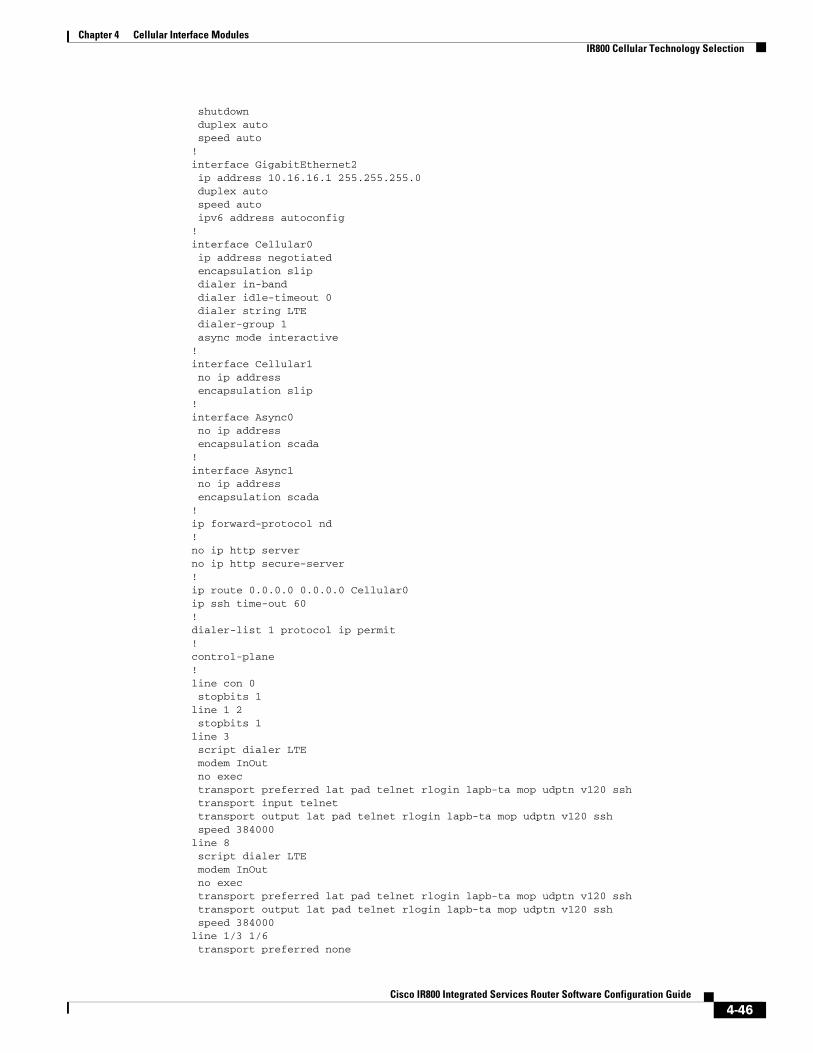
Chapter 4 Cellular Interface Modules IR800 Cellular Technology Selection
shutdown duplex auto speed auto!interface GigabitEthernet2 ip address 10.16.16.1 255.255.255.0 duplex auto speed auto ipv6 address autoconfig!interface Cellular0 ip address negotiated encapsulation slip dialer in-band dialer idle-timeout 0 dialer string LTE dialer-group 1 async mode interactive!interface Cellular1 no ip address encapsulation slip!interface Async0 no ip address encapsulation scada!interface Async1 no ip address encapsulation scada!ip forward-protocol nd!no ip http serverno ip http secure-server!ip route 0.0.0.0 0.0.0.0 Cellular0ip ssh time-out 60!dialer-list 1 protocol ip permit!control-plane!line con 0 stopbits 1line 1 2 stopbits 1line 3 script dialer LTE modem InOut no exec transport preferred lat pad telnet rlogin lapb-ta mop udptn v120 ssh transport input telnet transport output lat pad telnet rlogin lapb-ta mop udptn v120 ssh speed 384000line 8 script dialer LTE modem InOut no exec transport preferred lat pad telnet rlogin lapb-ta mop udptn v120 ssh transport output lat pad telnet rlogin lapb-ta mop udptn v120 ssh speed 384000line 1/3 1/6 transport preferred none
4-46Cisco IR800 Integrated Services Router Software Configuration Guide

Chapter 4 Cellular Interface Modules GPS
transport output none stopbits 1line vty 0 4 password cisco transport input telnet ssh!no scheduler max-task-time!end
IR800#
GPSThe IR800 series can be configured to enable real-time location tracking of remote assets and geo-fence when used with IOT Field Network Director. Field Network Director receives GPS data directly from IOS, not NMEA.
Key Points:
• GPS must be configured under controller cellular 0
• GPS can be assigned to Cellular AUX antenna
• GPS data can be seen locally or data stream can be forwarded to applications, i.e. RUBAN.
Note When installing dual modems, you can only configure GPS on modem 1. Not modem 2.
For information about the GPS LED indications and locations of the GPS connectors, see IR829 Product Overview and IR809 Product Overview.
To configure GPS on the IR800 series, refer to the following examples.
IR829# conf termIR829(config)#controller cellular 0IR829(config-controller)#lte gps ? enable enable GPS feature mode select GPS mode nmea enable NMEA data
IR829(config-controller)#lte gps mode standalone IR829(config-controller)#lte gps nmea ip
IR829#show cellular 0 gps
GPS Info-------------GPS Feature: enabledGPS Port Selected: Dedicated GPS portGPS State: GPS enabledGPS Mode Configured: standaloneLatitude: 48 Deg 38 Min 31.2114 Sec NorthLongitude: 2 Deg 13 Min 47.3992 Sec EastTimestamp (GMT): Wed Jul 22 08:05:28 2015
Fix type index: 0, Height: 94 mSatellite Info----------------
4-47Cisco IR800 Integrated Services Router Software Configuration Guide
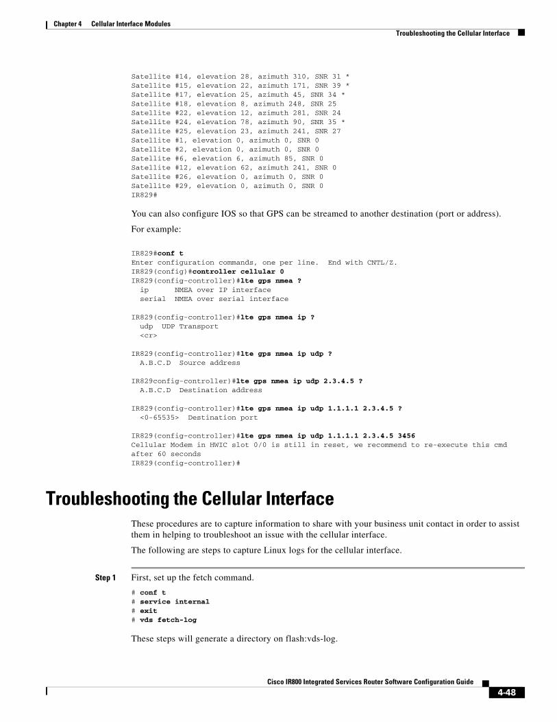
Chapter 4 Cellular Interface Modules Troubleshooting the Cellular Interface
Satellite #14, elevation 28, azimuth 310, SNR 31 *Satellite #15, elevation 22, azimuth 171, SNR 39 *Satellite #17, elevation 25, azimuth 45, SNR 34 *Satellite #18, elevation 8, azimuth 248, SNR 25 Satellite #22, elevation 12, azimuth 281, SNR 24 Satellite #24, elevation 78, azimuth 90, SNR 35 *Satellite #25, elevation 23, azimuth 241, SNR 27 Satellite #1, elevation 0, azimuth 0, SNR 0 Satellite #2, elevation 0, azimuth 0, SNR 0 Satellite #6, elevation 6, azimuth 85, SNR 0 Satellite #12, elevation 62, azimuth 241, SNR 0 Satellite #26, elevation 0, azimuth 0, SNR 0 Satellite #29, elevation 0, azimuth 0, SNR 0 IR829#
You can also configure IOS so that GPS can be streamed to another destination (port or address).
For example:
IR829#conf tEnter configuration commands, one per line. End with CNTL/Z.IR829(config)#controller cellular 0IR829(config-controller)#lte gps nmea ? ip NMEA over IP interface serial NMEA over serial interface
IR829(config-controller)#lte gps nmea ip ? udp UDP Transport <cr>
IR829(config-controller)#lte gps nmea ip udp ? A.B.C.D Source address
IR829config-controller)#lte gps nmea ip udp 2.3.4.5 ? A.B.C.D Destination address
IR829(config-controller)#lte gps nmea ip udp 1.1.1.1 2.3.4.5 ? <0-65535> Destination port
IR829(config-controller)#lte gps nmea ip udp 1.1.1.1 2.3.4.5 3456Cellular Modem in HWIC slot 0/0 is still in reset, we recommend to re-execute this cmd after 60 secondsIR829(config-controller)#
Troubleshooting the Cellular InterfaceThese procedures are to capture information to share with your business unit contact in order to assist them in helping to troubleshoot an issue with the cellular interface.
The following are steps to capture Linux logs for the cellular interface.
Step 1 First, set up the fetch command.
# conf t# service internal# exit# vds fetch-log
These steps will generate a directory on flash:vds-log.
4-48Cisco IR800 Integrated Services Router Software Configuration Guide

Chapter 4 Cellular Interface Modules Troubleshooting the Cellular Interface
Step 2 Next, capture the logs.
IR800# vds fetch-logfetch: 4gmodem.log Sending file modes: C0644 510 4gmodem.log
fetch: auth.log Sending file modes: C0640 162330 auth.log
fetch: auth.log.1 Sending file modes: C0640 262215 auth.log.1
fetch: auth.log.2.gz Sending file modes: C0640 11297 auth.log.2.gz
fetch: auth.log.3.gz Sending file modes: C0640 11296 auth.log.3.gz
fetch: cwan_modem0.log Sending file modes: C0644 3875716 cwan_modem0.log
fetch: cwan_modem1.log Sending file modes: C0644 791629 cwan_modem1.log
fetch: daemon.log Sending file modes: C0640 1404 daemon.log
fetch: dmesg Sending file modes: C0644 13740 dmesg
fetch: dmesg.0 Sending file modes: C0644 0 dmesg.0
fetch: ios_cs_verify.log Sending file modes: C0644 1091 ios_cs_verify.log
fetch: ios_vds_com.log Sending file modes: C0644 219169 ios_vds_com.log
fetch: ios_vds_com.log.1 Sending file modes: C0644 262207 ios_vds_com.log.1
fetch: ios_vds_com.log.2.gz Sending file modes: C0644 7859 ios_vds_com.log.2.gz
fetch: ios_vds_com.log.3.gz Sending file modes: C0644 7894 ios_vds_com.log.3.gz
fetch: kern.log Sending file modes: C0640 38608 kern.log
fetch: messages Sending file modes: C0640 174064 messages
fetch: messages.1 Sending file modes: C0640 262364 messages.1
fetch: messages.2.gzetch: messages.2.gz Sending file modes: C0640 18434 messages.2.gz
fetch: messages.3.gz Sending file modes: C0640 25027 messages.3.gz
4-49Cisco IR800 Integrated Services Router Software Configuration Guide
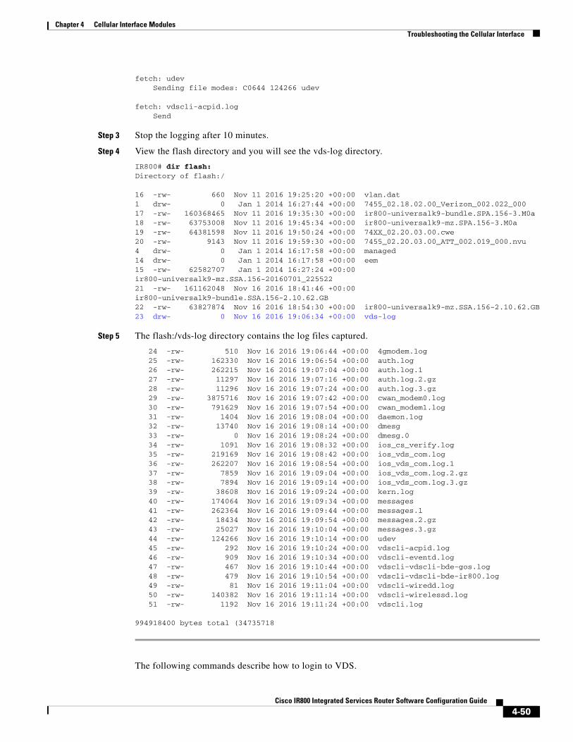
Chapter 4 Cellular Interface Modules Troubleshooting the Cellular Interface
fetch: udev Sending file modes: C0644 124266 udev
fetch: vdscli-acpid.log Send
Step 3 Stop the logging after 10 minutes.
Step 4 View the flash directory and you will see the vds-log directory.
IR800# dir flash:Directory of flash:/
16 -rw- 660 Nov 11 2016 19:25:20 +00:00 vlan.dat1 drw- 0 Jan 1 2014 16:27:44 +00:00 7455_02.18.02.00_Verizon_002.022_00017 -rw- 160368465 Nov 11 2016 19:35:30 +00:00 ir800-universalk9-bundle.SPA.156-3.M0a18 -rw- 63753008 Nov 11 2016 19:45:34 +00:00 ir800-universalk9-mz.SPA.156-3.M0a19 -rw- 64381598 Nov 11 2016 19:50:24 +00:00 74XX_02.20.03.00.cwe20 -rw- 9143 Nov 11 2016 19:59:30 +00:00 7455_02.20.03.00_ATT_002.019_000.nvu4 drw- 0 Jan 1 2014 16:17:58 +00:00 managed14 drw- 0 Jan 1 2014 16:17:58 +00:00 eem15 -rw- 62582707 Jan 1 2014 16:27:24 +00:00 ir800-universalk9-mz.SSA.156-20160701_22552221 -rw- 161162048 Nov 16 2016 18:41:46 +00:00 ir800-universalk9-bundle.SSA.156-2.10.62.GB22 -rw- 63827874 Nov 16 2016 18:54:30 +00:00 ir800-universalk9-mz.SSA.156-2.10.62.GB23 drw- 0 Nov 16 2016 19:06:34 +00:00 vds-log
Step 5 The flash:/vds-log directory contains the log files captured.
24 -rw- 510 Nov 16 2016 19:06:44 +00:00 4gmodem.log 25 -rw- 162330 Nov 16 2016 19:06:54 +00:00 auth.log 26 -rw- 262215 Nov 16 2016 19:07:04 +00:00 auth.log.1 27 -rw- 11297 Nov 16 2016 19:07:16 +00:00 auth.log.2.gz 28 -rw- 11296 Nov 16 2016 19:07:24 +00:00 auth.log.3.gz 29 -rw- 3875716 Nov 16 2016 19:07:42 +00:00 cwan_modem0.log 30 -rw- 791629 Nov 16 2016 19:07:54 +00:00 cwan_modem1.log 31 -rw- 1404 Nov 16 2016 19:08:04 +00:00 daemon.log 32 -rw- 13740 Nov 16 2016 19:08:14 +00:00 dmesg 33 -rw- 0 Nov 16 2016 19:08:24 +00:00 dmesg.0 34 -rw- 1091 Nov 16 2016 19:08:32 +00:00 ios_cs_verify.log 35 -rw- 219169 Nov 16 2016 19:08:42 +00:00 ios_vds_com.log 36 -rw- 262207 Nov 16 2016 19:08:54 +00:00 ios_vds_com.log.1 37 -rw- 7859 Nov 16 2016 19:09:04 +00:00 ios_vds_com.log.2.gz 38 -rw- 7894 Nov 16 2016 19:09:14 +00:00 ios_vds_com.log.3.gz 39 -rw- 38608 Nov 16 2016 19:09:24 +00:00 kern.log 40 -rw- 174064 Nov 16 2016 19:09:34 +00:00 messages 41 -rw- 262364 Nov 16 2016 19:09:44 +00:00 messages.1 42 -rw- 18434 Nov 16 2016 19:09:54 +00:00 messages.2.gz 43 -rw- 25027 Nov 16 2016 19:10:04 +00:00 messages.3.gz 44 -rw- 124266 Nov 16 2016 19:10:14 +00:00 udev 45 -rw- 292 Nov 16 2016 19:10:24 +00:00 vdscli-acpid.log 46 -rw- 909 Nov 16 2016 19:10:34 +00:00 vdscli-eventd.log 47 -rw- 467 Nov 16 2016 19:10:44 +00:00 vdscli-vdscli-bde-gos.log 48 -rw- 479 Nov 16 2016 19:10:54 +00:00 vdscli-vdscli-bde-ir800.log 49 -rw- 81 Nov 16 2016 19:11:04 +00:00 vdscli-wiredd.log 50 -rw- 140382 Nov 16 2016 19:11:14 +00:00 vdscli-wirelessd.log 51 -rw- 1192 Nov 16 2016 19:11:24 +00:00 vdscli.log
994918400 bytes total (34735718
The following commands describe how to login to VDS.
4-50Cisco IR800 Integrated Services Router Software Configuration Guide
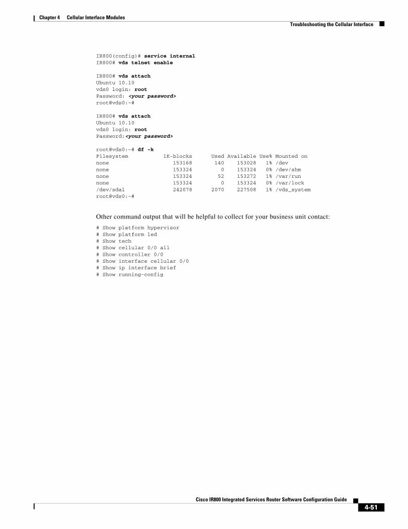
Chapter 4 Cellular Interface Modules Troubleshooting the Cellular Interface
IR800(config)# service internalIR800# vds telnet enable
IR800# vds attachUbuntu 10.10vds0 login: rootPassword: <your password>root@vds0:~#
IR800# vds attachUbuntu 10.10vds0 login: rootPassword:<your password>
root@vds0:~# df -kFilesystem 1K-blocks Used Available Use% Mounted onnone 153168 140 153028 1% /devnone 153324 0 153324 0% /dev/shmnone 153324 52 153272 1% /var/runnone 153324 0 153324 0% /var/lock/dev/sda1 242078 2070 227508 1% /vds_systemroot@vds0:~#
Other command output that will be helpful to collect for your business unit contact:
# Show platform hypervisor# Show platform led# Show tech# Show cellular 0/0 all# Show controller 0/0# Show interface cellular 0/0# Show ip interface brief # Show running-config
4-51Cisco IR800 Integrated Services Router Software Configuration Guide

Cisco IR800 Integr
C H A P T E R 5
IR829 AP803 Access Point ModuleThis chapter provides background on the Internal WLAN Access Point which runs on-board the IR829 router. The AP803 runs its own IOS software independently from the IR829 IOS, and requires configuring. The AP803 works as a standalone access point or with a wireless controller.
Hardware OverviewHighlights of the access point are:
• Atheros QCA9550 SoC + AR9592 radio
• 256MB DDR2 RAM + 128MB NAND Flash + 1MB Boot flash and configuration/calibration storage
• Dual simultaneous 2.4GHz and 5Ghz 802.11 radios
– Supports 2 x 2 802.11a/n MIMO and 2 x 2 802.11b/g/n MIMO
– Packet aggregation: A-MPDU (Tx/Rx), A-MSDU (Tx/Rx)
– 802.11 dynamic frequency selection (DFS)
– Cyclic shift diversity (CSD) support
– 20- and 40-MHz channels
– 802.11 dynamic frequency selection (DFS) – is applicable to IR829 AP803 and is available in IOS release 8.1MR2
Software OverviewThis Embedded AP supports a default Autonomous mode and a Unified mode. Both the Autonomous and Unified images are pre-loaded from Cisco on the access point’s flash memory.
The image name describes what each image is for. w7 is Autonomous Image, while w8 is the Unified mode (LWAP) Image. For example:
• Autonomous image – ap1g3-k9w7-tar.153-3.JBB1.tar
• Unified mode (LWAP) image – ap1g3-k9w8-tar.153-3.JBB1.tar
• To select the Autonomous or Unified image use the IOS CLI:
IR829(config)#service-module wlan-ap 0 bootimage autonomousIR829(config)#service-module wlan-ap 0 bootimage unified
5-52ated Services Router Software Configuration Guide
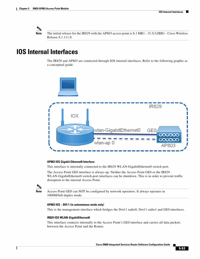
Chapter 5 IR829 AP803 Access Point Module IOS Internal Interfaces
Note The initial release for the IR829 with the AP803 access point is 8.1 MR1 - 15.3(3)JBB1 - Cisco Wireless Release 8.1.111.0.
IOS Internal InterfacesThe IR829 and AP803 are connected through IOS internal interfaces. Refer to the following graphic as a conceptual guide.
AP803 IOS Gigabit Ethernet0 Interface
This interface is internally connected to the IR829 WLAN-GigabitEthernet0 switch-port.
The Access Point GE0 interface is always up. Neither the Access Point GE0 or the IR829 WLAN-GigabitEthernet0 switch-port interfaces can be shutdown. This is in order to prevent traffic disruption to the internal Access Point.
Note Access Point GE0 can NOT be configured by network operators. It always operates in 1000M/full-duplex mode.
AP803 IOS – BVI 1 (in autonomous mode only)
This is the management interface which bridges the Dot11 radio0, Dot11 radio1 and GE0 interfaces.
IR829 IOS WLAN-GigabitEthernet0
This interface connects internally to the Access Point’s GE0 interface and carries all data packets between the Access Point and the Router.
5-53Cisco IR800 Integrated Services Router Software Configuration Guide
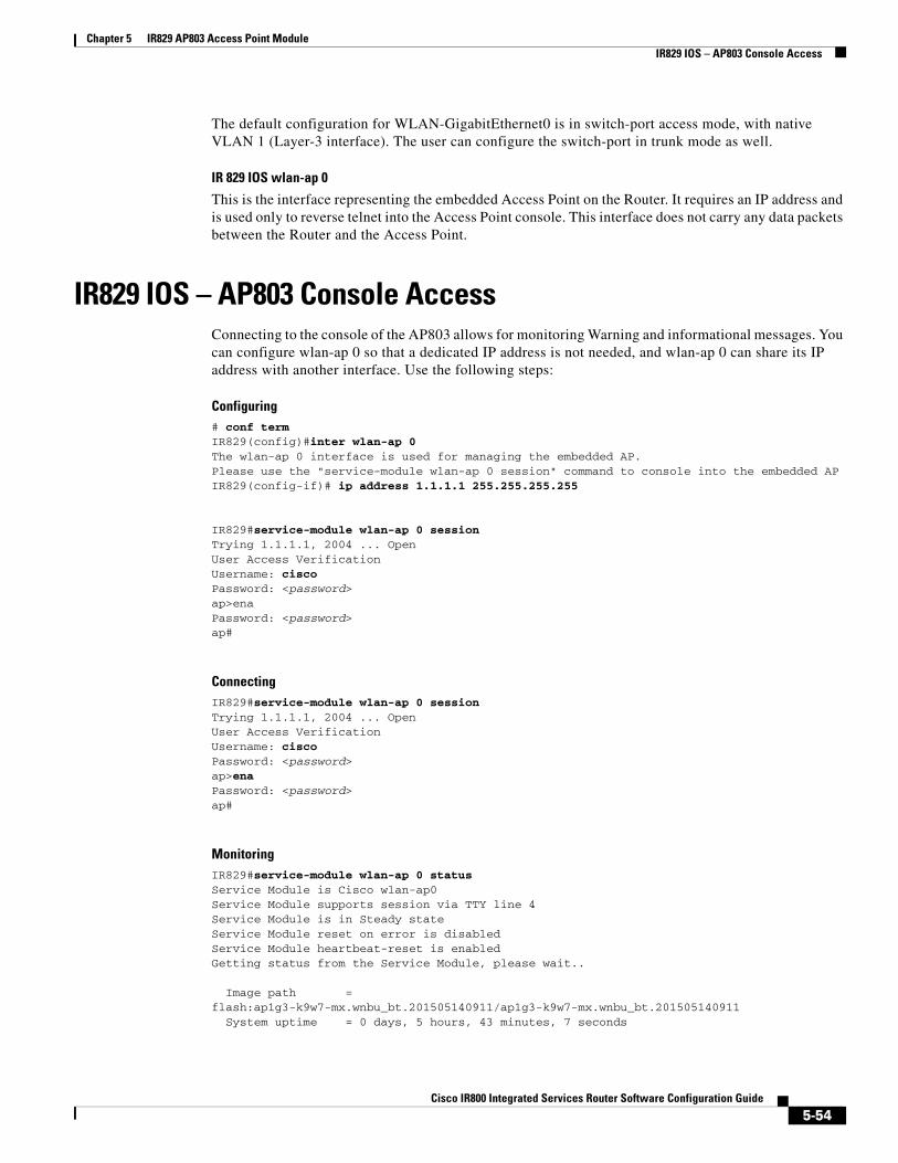
Chapter 5 IR829 AP803 Access Point Module IR829 IOS – AP803 Console Access
The default configuration for WLAN-GigabitEthernet0 is in switch-port access mode, with native VLAN 1 (Layer-3 interface). The user can configure the switch-port in trunk mode as well.
IR 829 IOS wlan-ap 0
This is the interface representing the embedded Access Point on the Router. It requires an IP address and is used only to reverse telnet into the Access Point console. This interface does not carry any data packets between the Router and the Access Point.
IR829 IOS – AP803 Console AccessConnecting to the console of the AP803 allows for monitoring Warning and informational messages. You can configure wlan-ap 0 so that a dedicated IP address is not needed, and wlan-ap 0 can share its IP address with another interface. Use the following steps:
Configuring# conf termIR829(config)#inter wlan-ap 0The wlan-ap 0 interface is used for managing the embedded AP.Please use the "service-module wlan-ap 0 session" command to console into the embedded APIR829(config-if)# ip address 1.1.1.1 255.255.255.255
IR829#service-module wlan-ap 0 sessionTrying 1.1.1.1, 2004 ... OpenUser Access VerificationUsername: ciscoPassword: <password>ap>enaPassword: <password>ap#
ConnectingIR829#service-module wlan-ap 0 sessionTrying 1.1.1.1, 2004 ... OpenUser Access VerificationUsername: ciscoPassword: <password>ap>enaPassword: <password>ap#
MonitoringIR829#service-module wlan-ap 0 status Service Module is Cisco wlan-ap0Service Module supports session via TTY line 4Service Module is in Steady stateService Module reset on error is disabledService Module heartbeat-reset is enabledGetting status from the Service Module, please wait..
Image path = flash:ap1g3-k9w7-mx.wnbu_bt.201505140911/ap1g3-k9w7-mx.wnbu_bt.201505140911 System uptime = 0 days, 5 hours, 43 minutes, 7 seconds
5-54Cisco IR800 Integrated Services Router Software Configuration Guide
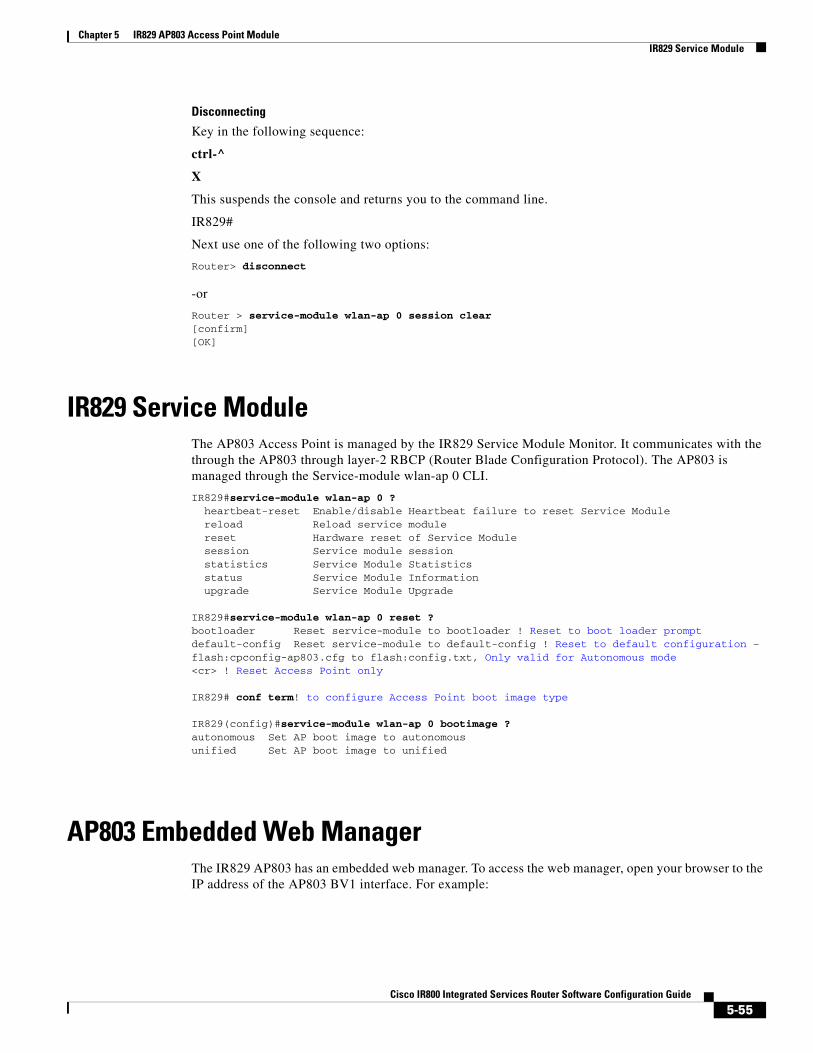
Chapter 5 IR829 AP803 Access Point Module IR829 Service Module
Disconnecting
Key in the following sequence:
ctrl-^
X
This suspends the console and returns you to the command line.
IR829#
Next use one of the following two options:
Router> disconnect
-or
Router > service-module wlan-ap 0 session clear[confirm][OK]
IR829 Service ModuleThe AP803 Access Point is managed by the IR829 Service Module Monitor. It communicates with the through the AP803 through layer-2 RBCP (Router Blade Configuration Protocol). The AP803 is managed through the Service-module wlan-ap 0 CLI.
IR829#service-module wlan-ap 0 ? heartbeat-reset Enable/disable Heartbeat failure to reset Service Module reload Reload service module reset Hardware reset of Service Module session Service module session statistics Service Module Statistics status Service Module Information upgrade Service Module Upgrade
IR829#service-module wlan-ap 0 reset ?bootloader Reset service-module to bootloader ! Reset to boot loader prompt default-config Reset service-module to default-config ! Reset to default configuration – flash:cpconfig-ap803.cfg to flash:config.txt, Only valid for Autonomous mode<cr> ! Reset Access Point only
IR829# conf term! to configure Access Point boot image type
IR829(config)#service-module wlan-ap 0 bootimage ?autonomous Set AP boot image to autonomousunified Set AP boot image to unified
AP803 Embedded Web ManagerThe IR829 AP803 has an embedded web manager. To access the web manager, open your browser to the IP address of the AP803 BV1 interface. For example:
5-55Cisco IR800 Integrated Services Router Software Configuration Guide

Chapter 5 IR829 AP803 Access Point Module Upgrading the Firmware on the AP803
The feature set for the AP803 is aligned with the Cisco Aironet 1532. More information can be found at:
Cisco Aironet 1530 Series
Upgrading the Firmware on the AP803The AP803 image is not included in the IR829 IOS bundle. The AP803 image must be installed separately after obtaining the new AP803 release from Cisco.com.
1. Log onto the AP803.
2. Install the new AP802 image using the archive command. Alternately, this can be accomplished through the embedded web interface.
• archive download-sw ! Software download.
• /overwrite ! Overwrites the software image in Flash with the downloaded image.
• /reload ! Reloads the system after downloading the image unless the configuration has been changed and not saved.
The ftp protocol to download the image is:
ftp://username:password@ipaddress/directory/file
For example:
IR829#service-module wlan-ap 0 session Trying 1.1.1.1, 2004 ... Open
ap#archive download-sw /over /reload ftp://username:[email protected]/Temp/ap1g3-k9w7-tar.153-3.JBB1.tar examining image...extracting info (285 bytes)!Image info: Version Suffix: k9w7-.153-3.JBB1 Image Name: ap1g3-k9w7-mx.153-3.JBB1
5-56Cisco IR800 Integrated Services Router Software Configuration Guide
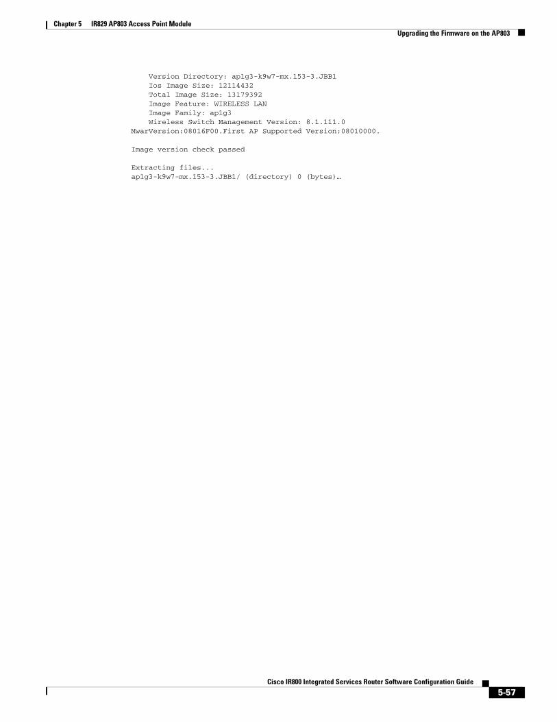
Chapter 5 IR829 AP803 Access Point Module Upgrading the Firmware on the AP803
Version Directory: ap1g3-k9w7-mx.153-3.JBB1 Ios Image Size: 12114432 Total Image Size: 13179392 Image Feature: WIRELESS LAN Image Family: ap1g3 Wireless Switch Management Version: 8.1.111.0MwarVersion:08016F00.First AP Supported Version:08010000.
Image version check passed
Extracting files...ap1g3-k9w7-mx.153-3.JBB1/ (directory) 0 (bytes)…
5-57Cisco IR800 Integrated Services Router Software Configuration Guide

Cisco IR800 Integr
C H A P T E R 6
Configuring Virtual-LPWAThis chapter describes the details of configuring virtual-LPWA (VLPWA) interface on the IR800 series for the configuration of the Cisco LoRaWAN Interface Module.
The Cisco LoRaWAN Interface Module is connected to IR800 series via an Ethernet cable with PoE+ to work as a LoRaWAN gateway. By creating a VLPWA interface on the IR800 series, you can:
• Manage hardware and software of the Cisco LoRaWAN Interface Module.
• Send and receive VLPWA protocol modem message to monitor the status of the Cisco LoRaWAN Interface Module.
• Send SNMP traps to the IoT Field Network Director (IoT FND).
Note Cisco IOS Release 15.6(3)M or later is required for the IR800 series to manage the Cisco LoRaWAN Interface Modules.
Note You need to install the Actility Thingpark LRR software as the LoRa forwarder firmware, which is loaded through the Cisco IOS software, for the Cisco LoRaWAN Interface Module to work.
You can find other documentation for the Cisco LoRaWAN Interface Module at:http://www.cisco.com/c/en/us/support/routers/interface-module-lorawan/tsd-products-support-series-home.html
Note Refer to the LoRa Alliance LoRaWAN 1.0 specifications for more information.
This chapter contains the following sections:
• Configuring VLPWA Interface on the IR800 Series, page 6-59
• Configuring SNMP TRAP for Modem Notifications, page 6-63
• Configuring VLPWA Interface and Associated Cisco LoRaWAN Interface Module, page 6-64
• Configuring Cisco LoRaWAN Interface Module Password, page 6-65
• Configuring Console Access, page 6-65
• Configuring Clock for the Cisco LoRaWAN Interface Module, page 6-65
• Configuring Cisco LoRaWAN Interface Module Timezone, page 6-67
• Configuring IPSec on the Cisco LoRaWAN Interface Module, page 6-67
6-58ated Services Router Software Configuration Guide
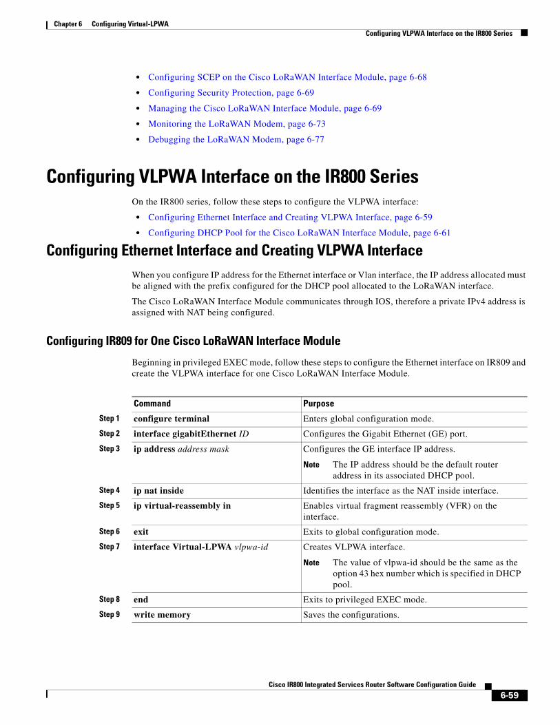
Chapter 6 Configuring Virtual-LPWA Configuring VLPWA Interface on the IR800 Series
• Configuring SCEP on the Cisco LoRaWAN Interface Module, page 6-68
• Configuring Security Protection, page 6-69
• Managing the Cisco LoRaWAN Interface Module, page 6-69
• Monitoring the LoRaWAN Modem, page 6-73
• Debugging the LoRaWAN Modem, page 6-77
Configuring VLPWA Interface on the IR800 SeriesOn the IR800 series, follow these steps to configure the VLPWA interface:
• Configuring Ethernet Interface and Creating VLPWA Interface, page 6-59
• Configuring DHCP Pool for the Cisco LoRaWAN Interface Module, page 6-61
Configuring Ethernet Interface and Creating VLPWA InterfaceWhen you configure IP address for the Ethernet interface or Vlan interface, the IP address allocated must be aligned with the prefix configured for the DHCP pool allocated to the LoRaWAN interface.
The Cisco LoRaWAN Interface Module communicates through IOS, therefore a private IPv4 address is assigned with NAT being configured.
Configuring IR809 for One Cisco LoRaWAN Interface Module
Beginning in privileged EXEC mode, follow these steps to configure the Ethernet interface on IR809 and create the VLPWA interface for one Cisco LoRaWAN Interface Module.
Command Purpose
Step 1 configure terminal Enters global configuration mode.
Step 2 interface gigabitEthernet ID Configures the Gigabit Ethernet (GE) port.
Step 3 ip address address mask Configures the GE interface IP address.
Note The IP address should be the default router address in its associated DHCP pool.
Step 4 ip nat inside Identifies the interface as the NAT inside interface.
Step 5 ip virtual-reassembly in Enables virtual fragment reassembly (VFR) on the interface.
Step 6 exit Exits to global configuration mode.
Step 7 interface Virtual-LPWA vlpwa-id Creates VLPWA interface.
Note The value of vlpwa-id should be the same as the option 43 hex number which is specified in DHCP pool.
Step 8 end Exits to privileged EXEC mode.
Step 9 write memory Saves the configurations.
6-59Cisco IR800 Integrated Services Router Software Configuration Guide

Chapter 6 Configuring Virtual-LPWA Configuring VLPWA Interface on the IR800 Series
Configuring IR809 for Multiple Cisco LoRaWAN Interface Modules
Beginning in privileged EXEC mode, follow these steps to configure the Ethernet interface on IR809 and create the VLPWA interface for multiple Cisco LoRaWAN Interface Modules.
Configuring IR829
Beginning in privileged EXEC mode, follow these steps to configure the Ethernet interface on IR829 and create the VLPWA interface.
Command Purpose
Step 1 configure terminal Enters global configuration mode.
Step 2 interface gigabitEthernet ID Configures the Gigabit Ethernet (GE) port.
Step 3 no shutdown Enables the interface.
Step 4 exit Exits to privileged EXEC mode.
Step 5 interface gigabitEthernet ID.subID Configures sub-interface on the GE port.
Step 6 encapsulation dot1Q vlpwa-id native Configures IEEE802.1Q encapsulation of traffic on a interface.
Step 7 ip address address mask Configures the GE interface IP address.
Note The IP address should be the default router address in its associated DHCP pool.
Step 8 ip nat inside Identifies the interface as the NAT inside interface.
Step 9 ip virtual-reassembly in Enables virtual fragment reassembly (VFR) on the interface.
Step 10 exit Exits to global configuration mode.
Step 11 interface Virtual-LPWA vlpwa-id Creates VLPWA interface.
Note The value of vlpwa-id should be the same as the option 43 hex number which is specified in DHCP pool.
Step 12 end Exits to privileged EXEC mode.
Step 13 write memory Saves the configurations.
Command Purpose
Step 1 configure terminal Enters global configuration mode.
Step 2 interface vlan vlan-id Configures the vlan interface.
Note The vlan-id should be assigned according to the hex value in option 43 in dhcp pool.
Step 3 ip address address mask Configures the vlan interface IP address.
Note IP address should be default router address in its associated DHCP pool.
Step 4 exit Exits to global configuration mode.
Step 5 interface gigabitEthernet ID Configures the Gigabit Ethernet port.
6-60Cisco IR800 Integrated Services Router Software Configuration Guide
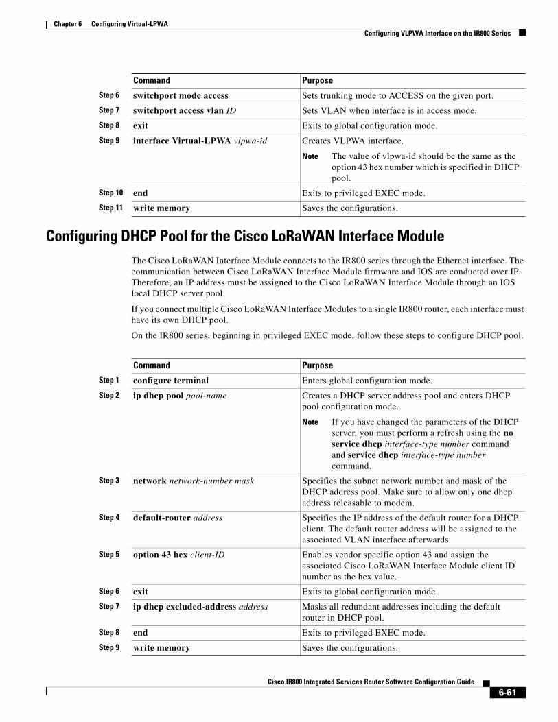
Chapter 6 Configuring Virtual-LPWA Configuring VLPWA Interface on the IR800 Series
Configuring DHCP Pool for the Cisco LoRaWAN Interface ModuleThe Cisco LoRaWAN Interface Module connects to the IR800 series through the Ethernet interface. The communication between Cisco LoRaWAN Interface Module firmware and IOS are conducted over IP. Therefore, an IP address must be assigned to the Cisco LoRaWAN Interface Module through an IOS local DHCP server pool.
If you connect multiple Cisco LoRaWAN Interface Modules to a single IR800 router, each interface must have its own DHCP pool.
On the IR800 series, beginning in privileged EXEC mode, follow these steps to configure DHCP pool.
Step 6 switchport mode access Sets trunking mode to ACCESS on the given port.
Step 7 switchport access vlan ID Sets VLAN when interface is in access mode.
Step 8 exit Exits to global configuration mode.
Step 9 interface Virtual-LPWA vlpwa-id Creates VLPWA interface.
Note The value of vlpwa-id should be the same as the option 43 hex number which is specified in DHCP pool.
Step 10 end Exits to privileged EXEC mode.
Step 11 write memory Saves the configurations.
Command Purpose
Command Purpose
Step 1 configure terminal Enters global configuration mode.
Step 2 ip dhcp pool pool-name Creates a DHCP server address pool and enters DHCP pool configuration mode.
Note If you have changed the parameters of the DHCP server, you must perform a refresh using the no service dhcp interface-type number command and service dhcp interface-type number command.
Step 3 network network-number mask Specifies the subnet network number and mask of the DHCP address pool. Make sure to allow only one dhcp address releasable to modem.
Step 4 default-router address Specifies the IP address of the default router for a DHCP client. The default router address will be assigned to the associated VLAN interface afterwards.
Step 5 option 43 hex client-ID Enables vendor specific option 43 and assign the associated Cisco LoRaWAN Interface Module client ID number as the hex value.
Step 6 exit Exits to global configuration mode.
Step 7 ip dhcp excluded-address address Masks all redundant addresses including the default router in DHCP pool.
Step 8 end Exits to privileged EXEC mode.
Step 9 write memory Saves the configurations.
6-61Cisco IR800 Integrated Services Router Software Configuration Guide

Chapter 6 Configuring Virtual-LPWA Configuring VLPWA Interface on the IR800 Series
Examples
The following is an example of configuring DHCP pool on IR809:
IR809#configure terminalIR809(config)#ip dhcp pool modempoolIR809(dhcp-config)#network 192.168.1.0 255.255.255.248IR809(dhcp-config)#default-router 192.168.1.1IR809(dhcp-config)#option 43 hex 01IR809(dhcp-config)#dns-server 192.168.1.1IR809(dhcp-config)#exitIR809(config)#IR809(config)#ip dhcp excluded-address 192.168.1.1IR809(config)#ip dhcp excluded-address 192.168.1.3 192.168.1.6IR809(config)#exitIR809#
The following is an example on IR809 using the sub-interface method:
ip dhcp excluded-address 192.168.1.1ip dhcp excluded-address 192.168.1.3 192.168.1.6!ip dhcp pool modempool1 network 192.168.1.0 255.255.255.248 default-router 192.168.1.1 option 43 hex 01!interface Virtual-LPWA1!interface GigabitEthernet1.101 encapsulation dot1Q 101 native ip address 192.168.1.1 255.255.255.248 ip nat inside ip virtual-reassembly in!end
The following is an example on IR829 using the VLAN method:
ip dhcp excluded-address 192.168.1.1ip dhcp excluded-address 192.168.1.3 192.168.1.6!ip dhcp pool modempool1 network 192.168.1.0 255.255.255.248 default-router 192.168.1.1 option 43 hex 01!interface Virtual-LPWA1!interface GigabitEthernet1 switchport access vlan 101!interface Vlan101 ip address 192.168.1.1 255.255.255.248!end
6-62Cisco IR800 Integrated Services Router Software Configuration Guide
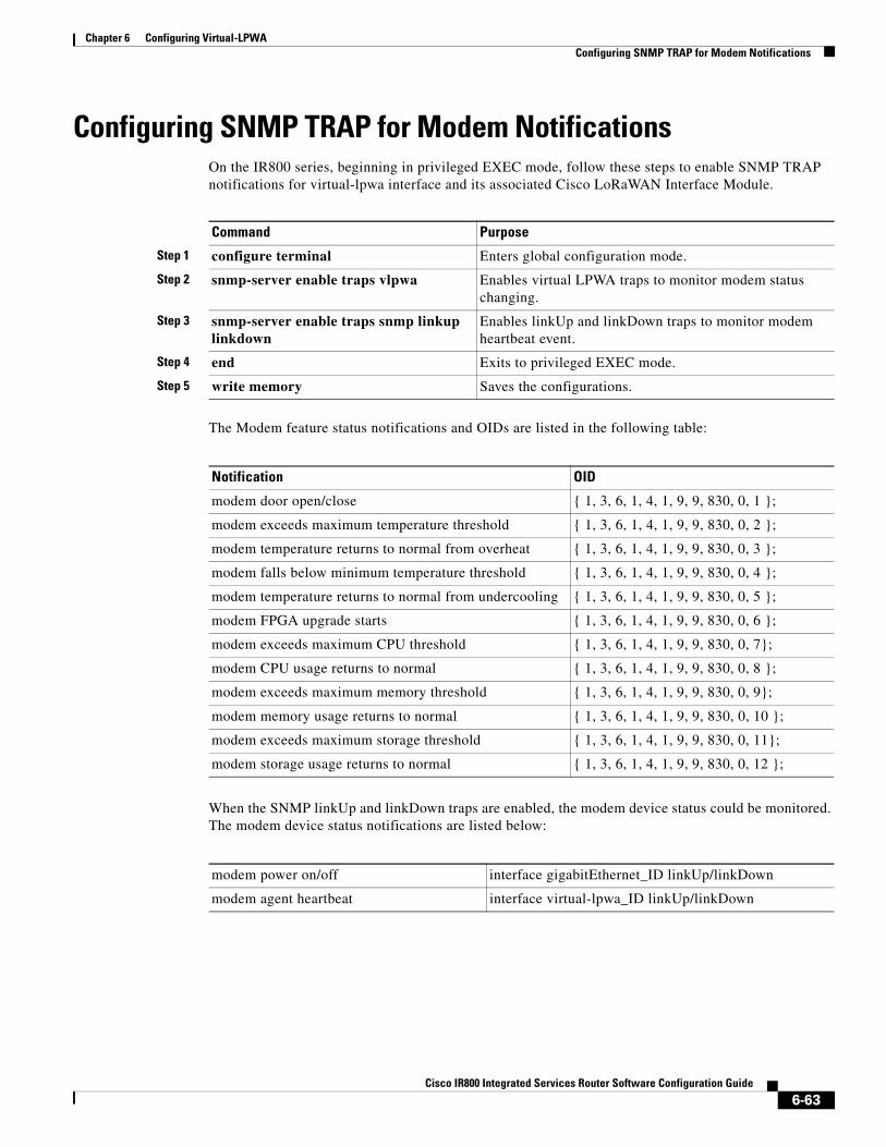
Chapter 6 Configuring Virtual-LPWA Configuring SNMP TRAP for Modem Notifications
Configuring SNMP TRAP for Modem NotificationsOn the IR800 series, beginning in privileged EXEC mode, follow these steps to enable SNMP TRAP notifications for virtual-lpwa interface and its associated Cisco LoRaWAN Interface Module.
The Modem feature status notifications and OIDs are listed in the following table:
When the SNMP linkUp and linkDown traps are enabled, the modem device status could be monitored. The modem device status notifications are listed below:
Command Purpose
Step 1 configure terminal Enters global configuration mode.
Step 2 snmp-server enable traps vlpwa Enables virtual LPWA traps to monitor modem status changing.
Step 3 snmp-server enable traps snmp linkup linkdown
Enables linkUp and linkDown traps to monitor modem heartbeat event.
Step 4 end Exits to privileged EXEC mode.
Step 5 write memory Saves the configurations.
Notification OID
modem door open/close { 1, 3, 6, 1, 4, 1, 9, 9, 830, 0, 1 };
modem exceeds maximum temperature threshold { 1, 3, 6, 1, 4, 1, 9, 9, 830, 0, 2 };
modem temperature returns to normal from overheat { 1, 3, 6, 1, 4, 1, 9, 9, 830, 0, 3 };
modem falls below minimum temperature threshold { 1, 3, 6, 1, 4, 1, 9, 9, 830, 0, 4 };
modem temperature returns to normal from undercooling { 1, 3, 6, 1, 4, 1, 9, 9, 830, 0, 5 };
modem FPGA upgrade starts { 1, 3, 6, 1, 4, 1, 9, 9, 830, 0, 6 };
modem exceeds maximum CPU threshold { 1, 3, 6, 1, 4, 1, 9, 9, 830, 0, 7};
modem CPU usage returns to normal { 1, 3, 6, 1, 4, 1, 9, 9, 830, 0, 8 };
modem exceeds maximum memory threshold { 1, 3, 6, 1, 4, 1, 9, 9, 830, 0, 9};
modem memory usage returns to normal { 1, 3, 6, 1, 4, 1, 9, 9, 830, 0, 10 };
modem exceeds maximum storage threshold { 1, 3, 6, 1, 4, 1, 9, 9, 830, 0, 11};
modem storage usage returns to normal { 1, 3, 6, 1, 4, 1, 9, 9, 830, 0, 12 };
modem power on/off interface gigabitEthernet_ID linkUp/linkDown
modem agent heartbeat interface virtual-lpwa_ID linkUp/linkDown
6-63Cisco IR800 Integrated Services Router Software Configuration Guide
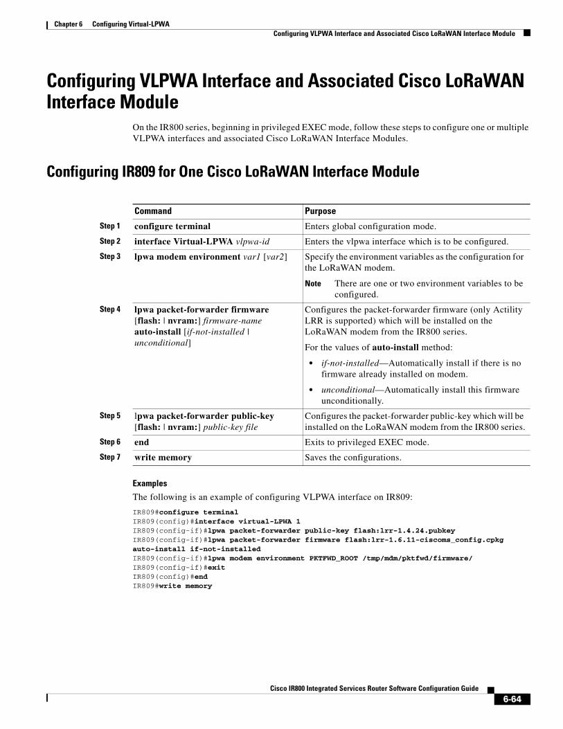
Chapter 6 Configuring Virtual-LPWA Configuring VLPWA Interface and Associated Cisco LoRaWAN Interface Module
Configuring VLPWA Interface and Associated Cisco LoRaWAN Interface Module
On the IR800 series, beginning in privileged EXEC mode, follow these steps to configure one or multiple VLPWA interfaces and associated Cisco LoRaWAN Interface Modules.
Configuring IR809 for One Cisco LoRaWAN Interface Module
Examples
The following is an example of configuring VLPWA interface on IR809:
IR809#configure terminalIR809(config)#interface virtual-LPWA 1IR809(config-if)#lpwa packet-forwarder public-key flash:lrr-1.4.24.pubkeyIR809(config-if)#lpwa packet-forwarder firmware flash:lrr-1.6.11-ciscoms_config.cpkg auto-install if-not-installedIR809(config-if)#lpwa modem environment PKTFWD_ROOT /tmp/mdm/pktfwd/firmware/IR809(config-if)#exitIR809(config)#endIR809#write memory
Command Purpose
Step 1 configure terminal Enters global configuration mode.
Step 2 interface Virtual-LPWA vlpwa-id Enters the vlpwa interface which is to be configured.
Step 3 lpwa modem environment var1 [var2] Specify the environment variables as the configuration for the LoRaWAN modem.
Note There are one or two environment variables to be configured.
Step 4 lpwa packet-forwarder firmware [flash: | nvram:] firmware-name auto-install [if-not-installed | unconditional]
Configures the packet-forwarder firmware (only Actility LRR is supported) which will be installed on the LoRaWAN modem from the IR800 series.
For the values of auto-install method:
• if-not-installed—Automatically install if there is no firmware already installed on modem.
• unconditional—Automatically install this firmware unconditionally.
Step 5 lpwa packet-forwarder public-key[flash: | nvram:] public-key file
Configures the packet-forwarder public-key which will be installed on the LoRaWAN modem from the IR800 series.
Step 6 end Exits to privileged EXEC mode.
Step 7 write memory Saves the configurations.
6-64Cisco IR800 Integrated Services Router Software Configuration Guide
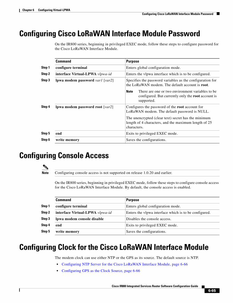
Chapter 6 Configuring Virtual-LPWA Configuring Cisco LoRaWAN Interface Module Password
Configuring Cisco LoRaWAN Interface Module PasswordOn the IR800 series, beginning in privileged EXEC mode, follow these steps to configure password for the Cisco LoRaWAN Interface Module.
Configuring Console Access
Note Configuring console access is not supported on release 1.0.20 and earlier.
On the IR800 series, beginning in privileged EXEC mode, follow these steps to configure console access for the Cisco LoRaWAN Interface Module. By default, the console access is enabled.
Configuring Clock for the Cisco LoRaWAN Interface ModuleThe modem clock can use either NTP or the GPS as its source. The default source is NTP.
• Configuring NTP Server for the Cisco LoRaWAN Interface Module, page 6-66
• Configuring GPS as the Clock Source, page 6-66
Command Purpose
Step 1 configure terminal Enters global configuration mode.
Step 2 interface Virtual-LPWA vlpwa-id Enters the vlpwa interface which is to be configured.
Step 3 lpwa modem password var1 [var2] Specifies the password variables as the configuration for the LoRaWAN modem. The default account is root.
Note There are one or two environment variables to be configured. But currently only the root account is supported.
Step 4 lpwa modem password root [var2] Configures the password of the root account for LoRaWAN modem. The default password is NULL.
The unencrypted (clear text) secret has the minimum length of 4 characters, and the maximum length of 25 characters.
Step 5 end Exits to privileged EXEC mode.
Step 6 write memory Saves the configurations.
Command Purpose
Step 1 configure terminal Enters global configuration mode.
Step 2 interface Virtual-LPWA vlpwa-id Enters the vlpwa interface which is to be configured.
Step 3 lpwa modem console disable Disables the console access.
Step 4 end Exits to privileged EXEC mode.
Step 5 write memory Saves the configurations.
6-65Cisco IR800 Integrated Services Router Software Configuration Guide
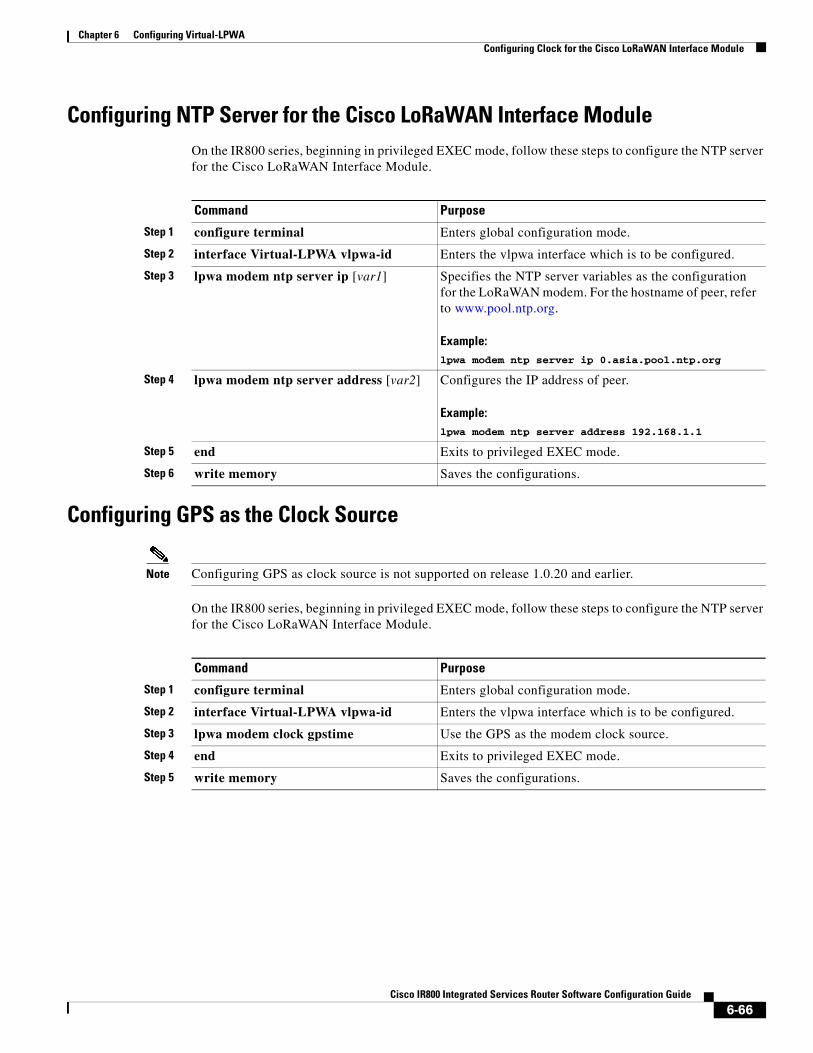
Chapter 6 Configuring Virtual-LPWA Configuring Clock for the Cisco LoRaWAN Interface Module
Configuring NTP Server for the Cisco LoRaWAN Interface ModuleOn the IR800 series, beginning in privileged EXEC mode, follow these steps to configure the NTP server for the Cisco LoRaWAN Interface Module.
Configuring GPS as the Clock Source
Note Configuring GPS as clock source is not supported on release 1.0.20 and earlier.
On the IR800 series, beginning in privileged EXEC mode, follow these steps to configure the NTP server for the Cisco LoRaWAN Interface Module.
Command Purpose
Step 1 configure terminal Enters global configuration mode.
Step 2 interface Virtual-LPWA vlpwa-id Enters the vlpwa interface which is to be configured.
Step 3 lpwa modem ntp server ip [var1] Specifies the NTP server variables as the configuration for the LoRaWAN modem. For the hostname of peer, refer to www.pool.ntp.org.
Example:lpwa modem ntp server ip 0.asia.pool.ntp.org
Step 4 lpwa modem ntp server address [var2] Configures the IP address of peer.
Example:lpwa modem ntp server address 192.168.1.1
Step 5 end Exits to privileged EXEC mode.
Step 6 write memory Saves the configurations.
Command Purpose
Step 1 configure terminal Enters global configuration mode.
Step 2 interface Virtual-LPWA vlpwa-id Enters the vlpwa interface which is to be configured.
Step 3 lpwa modem clock gpstime Use the GPS as the modem clock source.
Step 4 end Exits to privileged EXEC mode.
Step 5 write memory Saves the configurations.
6-66Cisco IR800 Integrated Services Router Software Configuration Guide

Chapter 6 Configuring Virtual-LPWA Configuring Cisco LoRaWAN Interface Module Timezone
Configuring Cisco LoRaWAN Interface Module TimezoneOn the IR800 series, beginning in privileged EXEC mode, follow these steps to configure timezone for the Cisco LoRaWAN Interface Module.
Configuring IPSec on the Cisco LoRaWAN Interface ModuleOn the IR800 series, beginning in privileged EXEC mode, follow these steps to configure IPSec for the Cisco LoRaWAN Interface Module.
Note Only PSK (IKEv1) and RSA (IKEv2) are supported.
Command Purpose
Step 1 configure terminal Enters global configuration mode.
Step 2 interface Virtual-LPWA vlpwa-id Enters the vlpwa interface which is to be configured.
Step 3 lpwa modem timezone [timezone] Specifies the timezone variables as the configuration for the LoRaWAN modem. The value is based on the IANA Timezone database. Please check the /usr/share/zoneinfo/ folder in your PC host.
timezone—Name of time zone, for example, Asia/Shanghai.
Example:lpwa modem timezone Asia/Shanghai
Step 4 end Exits to privileged EXEC mode.
Step 5 write memory Saves the configurations.
Command Purpose
Step 1 configure terminal Enters global configuration mode.
Step 2 interface Virtual-LPWA vlpwa-id Enters the vlpwa interface which is to be configured.
Step 3 lpwa modem ipsec enable Enables IPSec. By default, IPSec is disabled.
Step 4 lpwa modem isakmp <xauth-user> <xauth-pw> <peer-ip> group <name> <psk-key> <lifetime>
Specifies the XAUTH credential’s username, password, and the IP address of the right participant’s interface. Matches this information to the IKEID group with group name, pre-shared key for remote peer, and lifetime in seconds.
Step 5 end Exits to privileged EXEC mode.
Step 6 write memory Saves the configurations.
6-67Cisco IR800 Integrated Services Router Software Configuration Guide
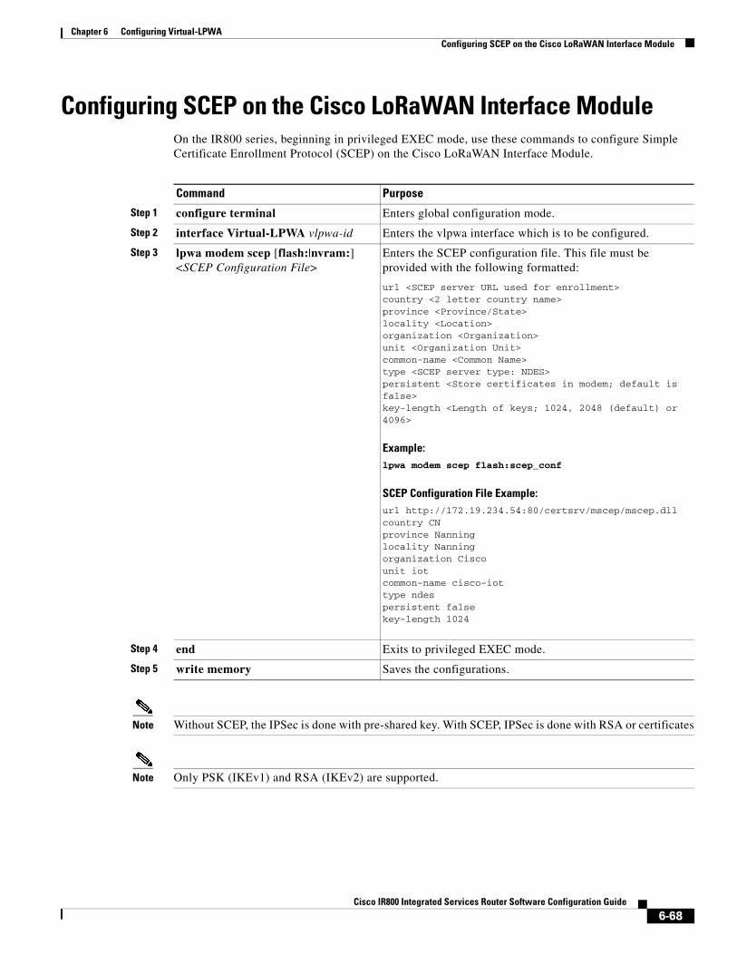
Chapter 6 Configuring Virtual-LPWA Configuring SCEP on the Cisco LoRaWAN Interface Module
Configuring SCEP on the Cisco LoRaWAN Interface ModuleOn the IR800 series, beginning in privileged EXEC mode, use these commands to configure Simple Certificate Enrollment Protocol (SCEP) on the Cisco LoRaWAN Interface Module.
Note Without SCEP, the IPSec is done with pre-shared key. With SCEP, IPSec is done with RSA or certificates
Note Only PSK (IKEv1) and RSA (IKEv2) are supported.
Command Purpose
Step 1 configure terminal Enters global configuration mode.
Step 2 interface Virtual-LPWA vlpwa-id Enters the vlpwa interface which is to be configured.
Step 3 lpwa modem scep [flash:|nvram:] <SCEP Configuration File>
Enters the SCEP configuration file. This file must be provided with the following formatted:
url <SCEP server URL used for enrollment>country <2 letter country name>province <Province/State>locality <Location>organization <Organization>unit <Organization Unit>common-name <Common Name>type <SCEP server type: NDES>persistent <Store certificates in modem; default is false>key-length <Length of keys; 1024, 2048 (default) or 4096>
Example:lpwa modem scep flash:scep_conf
SCEP Configuration File Example:url http://172.19.234.54:80/certsrv/mscep/mscep.dllcountry CNprovince Nanninglocality Nanningorganization Ciscounit iotcommon-name cisco-iottype ndespersistent falsekey-length 1024
Step 4 end Exits to privileged EXEC mode.
Step 5 write memory Saves the configurations.
6-68Cisco IR800 Integrated Services Router Software Configuration Guide
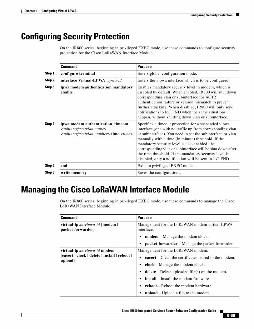
Chapter 6 Configuring Virtual-LPWA Configuring Security Protection
Configuring Security ProtectionOn the IR800 series, beginning in privileged EXEC mode, use these commands to configure security protection for the Cisco LoRaWAN Interface Module.
Managing the Cisco LoRaWAN Interface ModuleOn the IR800 series, beginning in privileged EXEC mode, use these commands to manage the Cisco LoRaWAN Interface Module.
Command Purpose
Step 1 configure terminal Enters global configuration mode.
Step 2 interface Virtual-LPWA vlpwa-id Enters the vlpwa interface which is to be configured.
Step 3 lpwa modem authentication mandatory enable
Enables mandatory security level in modem, which is disabled by default. When enabled, IR800 will shut down corresponding vlan or subinterface for ACT2 authentication failure or version mismatch to prevent further attacking. When disabled, IR800 will only send notifications to IoT FND when the same situations happen, without shutting down vlan or subinterface.
Step 4 lpwa modem authentication timeout <subinterface/vlan name> <subinterface/vlan number> time <time>
Specifies a timeout protection for a suspended vlpwa interface (one with no traffic up from corresponding vlan or subinterface). You need to set the subinterface or vlan manually with a time (in minute) threshold. If the mandatory security level is also enabled, the corresponding vlan or subinterface will be shut down after the time threshold. If the mandatory security level is disabled, only a notification will be sent to IoT FND.
Step 5 end Exits to privileged EXEC mode.
Step 6 write memory Saves the configurations.
Command Purpose
virtual-lpwa vlpwa-id [modem | packet-forwarder]
Management for the LoRaWAN modem virtual-LPWA interface:
• modem—Manage the modem clock.
• packet-forwarder—Manage the packet forwarder.
virtual-lpwa vlpwa-id modem[cacert | clock | delete | install | reboot | upload]
Management for the LoRaWAN modem:
• cacert—Clean the certificates stored in the modem.
• clock—Manage the modem clock.
• delete—Delete uploaded file(s) on the modem.
• install—Install the modem firmware.
• reboot—Reboot the modem hardware.
• upload—Upload a file to the modem.
6-69Cisco IR800 Integrated Services Router Software Configuration Guide

Chapter 6 Configuring Virtual-LPWA Managing the Cisco LoRaWAN Interface Module
Examples
The following is an example of setting the clock for the Cisco LoRaWAN Interface Module:
IR829#virtual-lpwa 10 modem clock set 12:02:40 15 Apr 2016Name: Virtual-LPWA 10
The following is an example of rebooting the Cisco LoRaWAN Interface Module:
IR829#virtual-lpwa 10 modem rebootName: Virtual-LPWA 10 Modem reboot initiated.
The following is an example of restarting packet-forwarder:
IR829#virtual-lpwa 10 packet-forwarder restartName: Virtual-LPWA 10 Restarted
LoRaWAN Modem Firmware UpgradeThere are three methods to upgrade the LoRaWAN modem firmware image:
• Normal—It takes over 5 minutes to install the image.
• TFTP server—It takes over 3 minutes to install the image.
• External TFTP server—It takes more time than the other two methods, considering the unexpected network accessibility of a user-customized TFTP server.
Use the virtual-lpwa 1 modem install firmware command to upgrade the Cisco LoRaWAN Interface Module firmware. The following upgrade options are available:
• external-tftp-factory—Install the firmware from external tftp and wipe user data on the LoRaWAN modem.
• external-tftp-normal—Install the firmware from external tftp and keep user data on the LoRaWAN modem.
• factory—Install the firmware and wipe the user data on the LoRaWAN modem.
virtual-lpwa vlpwa-id packet-forwarder[install | restart | start | stop | uninstall]
Management for the LoRaWAN modem packet-forwarder:
• install—Install firmware or public key.
• restart—Restart packet-forwarder.
• start—Start packet-forwarder.
• stop—Stop packet-forwarder.
• uninstall—Uninstall firmware or public key.
virtual-lpwa vlpwa-id modem clock set hh:mm:ss {dd Mon yyyy}
Management the clock for the LoRaWAN modem:
hh:mm:ss:—Current time.
dd Mon yyyy—Day, month, and year.
Example:virtual-lpwa vlpwa-id modem clock set 20:30:30 31 Mar 2016
Command Purpose
6-70Cisco IR800 Integrated Services Router Software Configuration Guide
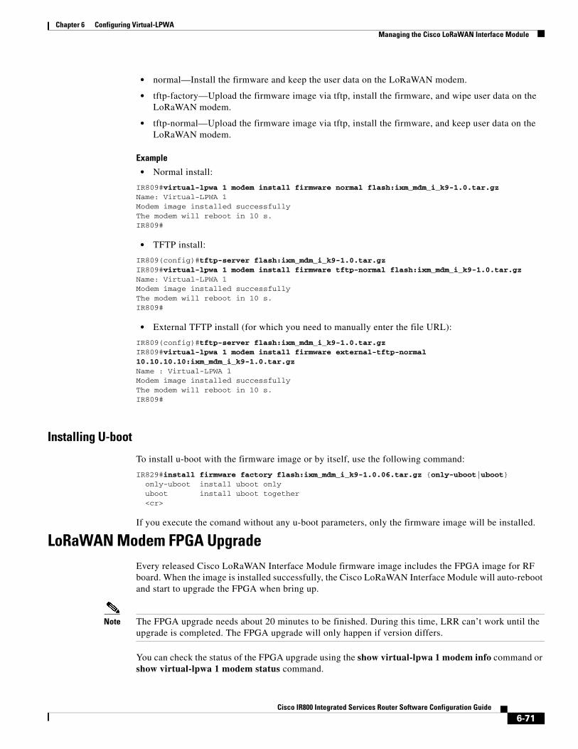
Chapter 6 Configuring Virtual-LPWA Managing the Cisco LoRaWAN Interface Module
• normal—Install the firmware and keep the user data on the LoRaWAN modem.
• tftp-factory—Upload the firmware image via tftp, install the firmware, and wipe user data on the LoRaWAN modem.
• tftp-normal—Upload the firmware image via tftp, install the firmware, and keep user data on the LoRaWAN modem.
Example
• Normal install:
IR809#virtual-lpwa 1 modem install firmware normal flash:ixm_mdm_i_k9-1.0.tar.gzName: Virtual-LPWA 1Modem image installed successfullyThe modem will reboot in 10 s. IR809#
• TFTP install:
IR809(config)#tftp-server flash:ixm_mdm_i_k9-1.0.tar.gzIR809#virtual-lpwa 1 modem install firmware tftp-normal flash:ixm_mdm_i_k9-1.0.tar.gzName: Virtual-LPWA 1Modem image installed successfullyThe modem will reboot in 10 s. IR809#
• External TFTP install (for which you need to manually enter the file URL):
IR809(config)#tftp-server flash:ixm_mdm_i_k9-1.0.tar.gzIR809#virtual-lpwa 1 modem install firmware external-tftp-normal 10.10.10.10:ixm_mdm_i_k9-1.0.tar.gzName : Virtual-LPWA 1Modem image installed successfullyThe modem will reboot in 10 s. IR809#
Installing U-boot
To install u-boot with the firmware image or by itself, use the following command:
IR829#install firmware factory flash:ixm_mdm_i_k9-1.0.06.tar.gz {only-uboot|uboot} only-uboot install uboot only uboot install uboot together <cr>
If you execute the comand without any u-boot parameters, only the firmware image will be installed.
LoRaWAN Modem FPGA UpgradeEvery released Cisco LoRaWAN Interface Module firmware image includes the FPGA image for RF board. When the image is installed successfully, the Cisco LoRaWAN Interface Module will auto-reboot and start to upgrade the FPGA when bring up.
Note The FPGA upgrade needs about 20 minutes to be finished. During this time, LRR can’t work until the upgrade is completed. The FPGA upgrade will only happen if version differs.
You can check the status of the FPGA upgrade using the show virtual-lpwa 1 modem info command or show virtual-lpwa 1 modem status command.
6-71Cisco IR800 Integrated Services Router Software Configuration Guide
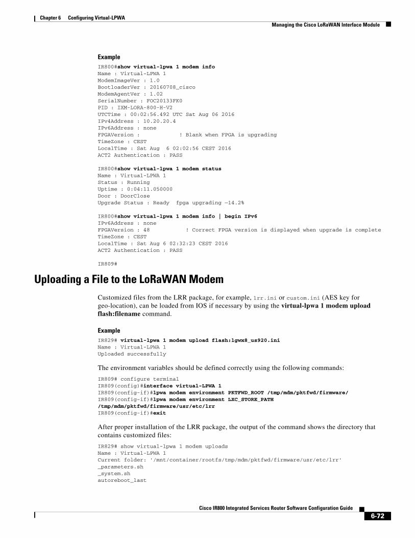
Chapter 6 Configuring Virtual-LPWA Managing the Cisco LoRaWAN Interface Module
ExampleIR800#show virtual-lpwa 1 modem infoName : Virtual-LPWA 1 ModemImageVer : 1.0BootloaderVer : 20160708_ciscoModemAgentVer : 1.02SerialNumber : FOC20133FK0PID : IXM-LORA-800-H-V2UTCTime : 00:02:56.492 UTC Sat Aug 06 2016IPv4Address : 10.20.20.4IPv6Address : noneFPGAVersion : ! Blank when FPGA is upgradingTimeZone : CESTLocalTime : Sat Aug 6 02:02:56 CEST 2016ACT2 Authentication : PASS
IR800#show virtual-lpwa 1 modem statusName : Virtual-LPWA 1 Status : RunningUptime : 0:04:11.050000Door : DoorCloseUpgrade Status : Ready fpga upgrading —14.2%
IR800#show virtual-lpwa 1 modem info | begin IPv6IPv6Address : noneFPGAVersion : 48 ! Correct FPGA version is displayed when upgrade is completeTimeZone : CESTLocalTime : Sat Aug 6 02:32:23 CEST 2016ACT2 Authentication : PASS
IR809#
Uploading a File to the LoRaWAN ModemCustomized files from the LRR package, for example, lrr.ini or custom.ini (AES key for geo-location), can be loaded from IOS if necessary by using the virtual-lpwa 1 modem upload flash:filename command.
ExampleIR829# virtual-lpwa 1 modem upload flash:lgwx8_us920.iniName : Virtual-LPWA 1 Uploaded successfully
The environment variables should be defined correctly using the following commands:
IR809# configure terminalIR809(config)#interface virtual-LPWA 1IR809(config-if)#lpwa modem environment PKTFWD_ROOT /tmp/mdm/pktfwd/firmware/IR809(config-if)#lpwa modem environment LXC_STORE_PATH /tmp/mdm/pktfwd/firmware/usr/etc/lrrIR809(config-if)#exit
After proper installation of the LRR package, the output of the command shows the directory that contains customized files:
IR829# show virtual-lpwa 1 modem uploadsName : Virtual-LPWA 1 Current folder: '/mnt/container/rootfs/tmp/mdm/pktfwd/firmware/usr/etc/lrr'_parameters.sh_system.shautoreboot_last
6-72Cisco IR800 Integrated Services Router Software Configuration Guide
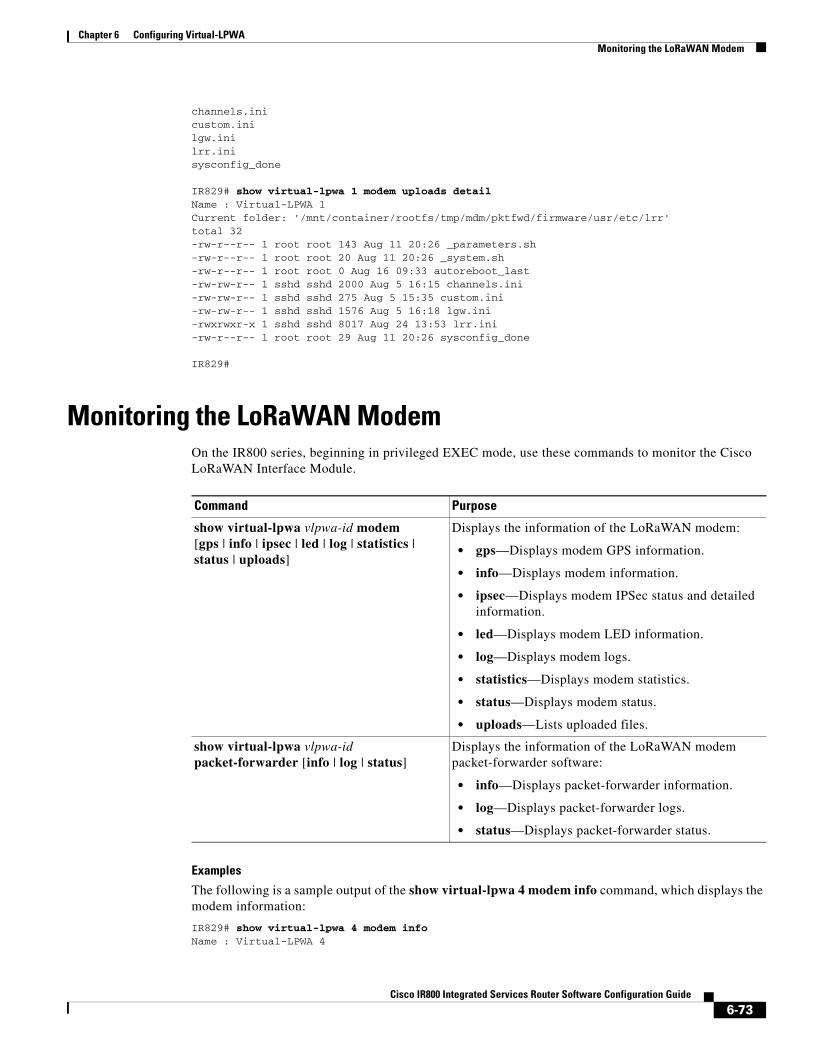
Chapter 6 Configuring Virtual-LPWA Monitoring the LoRaWAN Modem
channels.inicustom.inilgw.inilrr.inisysconfig_done
IR829# show virtual-lpwa 1 modem uploads detailName : Virtual-LPWA 1 Current folder: '/mnt/container/rootfs/tmp/mdm/pktfwd/firmware/usr/etc/lrr'total 32-rw-r--r-- 1 root root 143 Aug 11 20:26 _parameters.sh-rw-r--r-- 1 root root 20 Aug 11 20:26 _system.sh-rw-r--r-- 1 root root 0 Aug 16 09:33 autoreboot_last-rw-rw-r-- 1 sshd sshd 2000 Aug 5 16:15 channels.ini-rw-rw-r-- 1 sshd sshd 275 Aug 5 15:35 custom.ini-rw-rw-r-- 1 sshd sshd 1576 Aug 5 16:18 lgw.ini-rwxrwxr-x 1 sshd sshd 8017 Aug 24 13:53 lrr.ini-rw-r--r-- 1 root root 29 Aug 11 20:26 sysconfig_done
IR829#
Monitoring the LoRaWAN ModemOn the IR800 series, beginning in privileged EXEC mode, use these commands to monitor the Cisco LoRaWAN Interface Module.
Examples
The following is a sample output of the show virtual-lpwa 4 modem info command, which displays the modem information:
IR829# show virtual-lpwa 4 modem infoName : Virtual-LPWA 4
Command Purpose
show virtual-lpwa vlpwa-id modem[gps | info | ipsec | led | log | statistics | status | uploads]
Displays the information of the LoRaWAN modem:
• gps—Displays modem GPS information.
• info—Displays modem information.
• ipsec—Displays modem IPSec status and detailed information.
• led—Displays modem LED information.
• log—Displays modem logs.
• statistics—Displays modem statistics.
• status—Displays modem status.
• uploads—Lists uploaded files.
show virtual-lpwa vlpwa-id packet-forwarder [info | log | status]
Displays the information of the LoRaWAN modem packet-forwarder software:
• info—Displays packet-forwarder information.
• log—Displays packet-forwarder logs.
• status—Displays packet-forwarder status.
6-73Cisco IR800 Integrated Services Router Software Configuration Guide
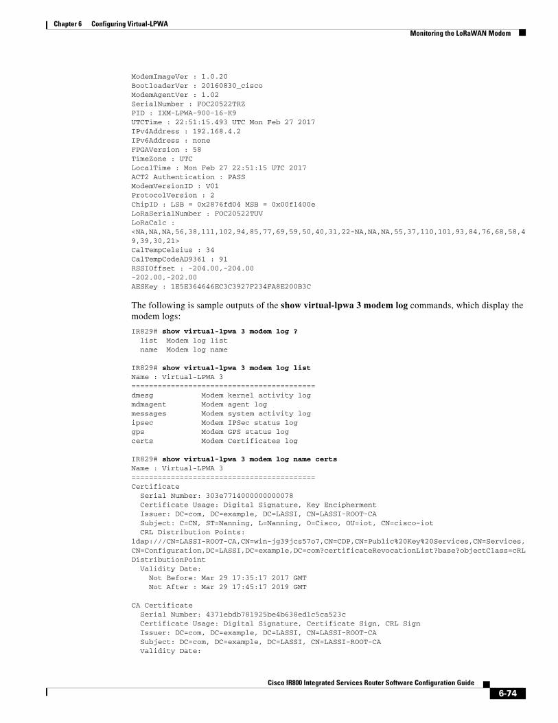
Chapter 6 Configuring Virtual-LPWA Monitoring the LoRaWAN Modem
ModemImageVer : 1.0.20BootloaderVer : 20160830_ciscoModemAgentVer : 1.02SerialNumber : FOC20522TRZPID : IXM-LPWA-900-16-K9UTCTime : 22:51:15.493 UTC Mon Feb 27 2017IPv4Address : 192.168.4.2IPv6Address : noneFPGAVersion : 58TimeZone : UTCLocalTime : Mon Feb 27 22:51:15 UTC 2017ACT2 Authentication : PASSModemVersionID : V01ProtocolVersion : 2ChipID : LSB = 0x2876fd04 MSB = 0x00f1400eLoRaSerialNumber : FOC20522TUVLoRaCalc : <NA,NA,NA,56,38,111,102,94,85,77,69,59,50,40,31,22-NA,NA,NA,55,37,110,101,93,84,76,68,58,49,39,30,21>CalTempCelsius : 34CalTempCodeAD9361 : 91RSSIOffset : -204.00,-204.00-202.00,-202.00AESKey : 1E5E364646EC3C3927F234FA8E200B3C
The following is sample outputs of the show virtual-lpwa 3 modem log commands, which display the modem logs:
IR829# show virtual-lpwa 3 modem log ? list Modem log list name Modem log name
IR829# show virtual-lpwa 3 modem log listName : Virtual-LPWA 3 ==========================================dmesg Modem kernel activity logmdmagent Modem agent logmessages Modem system activity logipsec Modem IPSec status loggps Modem GPS status logcerts Modem Certificates log
IR829# show virtual-lpwa 3 modem log name certsName : Virtual-LPWA 3 ==========================================Certificate Serial Number: 303e7714000000000078 Certificate Usage: Digital Signature, Key Encipherment Issuer: DC=com, DC=example, DC=LASSI, CN=LASSI-ROOT-CA Subject: C=CN, ST=Nanning, L=Nanning, O=Cisco, OU=iot, CN=cisco-iot CRL Distribution Points:ldap:///CN=LASSI-ROOT-CA,CN=win-jg39jcs57o7,CN=CDP,CN=Public%20Key%20Services,CN=Services,CN=Configuration,DC=LASSI,DC=example,DC=com?certificateRevocationList?base?objectClass=cRLDistributionPoint Validity Date: Not Before: Mar 29 17:35:17 2017 GMT Not After : Mar 29 17:45:17 2019 GMT
CA Certificate Serial Number: 4371ebdb781925be4b638ed1c5ca523c Certificate Usage: Digital Signature, Certificate Sign, CRL Sign Issuer: DC=com, DC=example, DC=LASSI, CN=LASSI-ROOT-CA Subject: DC=com, DC=example, DC=LASSI, CN=LASSI-ROOT-CA Validity Date:
6-74Cisco IR800 Integrated Services Router Software Configuration Guide

Chapter 6 Configuring Virtual-LPWA Monitoring the LoRaWAN Modem
Not Before: Dec 2 21:34:38 2016 GMT Not After : Dec 2 21:44:38 2021 GMT
IR829#show virtual-lpwa 10 modem log name dmesgName: Virtual-LPWA 10==========================================2016-06-03T07:21:23+08:00 lorawan kernel: ttyS1: 1 input overrun(s)2016-06-03T07:32:26+08:00 lorawan kernel: ttyS1: 1 input overrun(s)2016-06-03T07:43:29+08:00 lorawan kernel: ttyS1: 1 input overrun(s)2016-06-03T07:54:32+08:00 lorawan kernel: ttyS1: 1 input overrun(s)2016-06-03T08:05:35+08:00 lorawan kernel: ttyS1: 1 input overrun(s)2016-06-03T08:16:38+08:00 lorawan kernel: ttyS1: 1 input overrun(s)2016-06-03T08:27:41+08:00 lorawan kernel: ttyS1: 1 input overrun(s)2016-06-03T08:38:44+08:00 lorawan kernel: ttyS1: 1 input overrun(s)2016-06-03T08:49:47+08:00 lorawan kernel: ttyS1: 1 input overrun(s)2016-06-03T09:00:50+08:00 lorawan kernel: ttyS1: 1 input overrun(s)
The following is a sample output of the show virtual-lpwa 10 modem statistics command, which displays the modem statistics information:
IR829#show virtual-lpwa 10 modem statisticsName: Virtual-LPWA 10 Load Average: 0.00 0.04 0.05Memory Usage: 0.22Flash Usage: sys:0.03 app:0.04Temperature: 44.5 C
The following is a sample output of the show virtual-lpwa 10 modem status command, which displays the modem status information:
IR829#show virtual-lpwa 10 modem statusName: Virtual-LPWA 10 Status: RunningUptime: 13:40:37.500000Door: DoorCloseUpgrade Status: Ready
The following is a sample output of the show virtual-lpwa 1 packet-forwarder info command, which displays the packet-forwarder information, and the LRRID which is required when registering a LoRaWAN interface on Actility Thingpark LoRaWAN network server:
IR829#show virtual-lpwa 1 packet-forwarder infoName : Virtual-LPWA 1 PublicKeyStatus : InstalledFirmwareStatus : InstalledPacketFwdVersion : 1.8.15LRRID : 68ba477ePartnerID : 0001
The following is a sample output of the show virtual-lpwa 10 packet-forwarder status command, which displays the packet-forwarder status:
IR829#show virtual-lpwa 10 packet-forwarder statusName: Virtual-LPWA 10 Status: Running
The following is a sample output of the show virtual-lpwa 10 packet-forwarder log list command, which displays the packet-forwarder log list:
IR829#show virtual-lpwa 10 packet-forwarder log listName: Virtual-LPWA 10 ==========================================lrr.ini lrr.ini informationconfig Get the detail config
6-75Cisco IR800 Integrated Services Router Software Configuration Guide
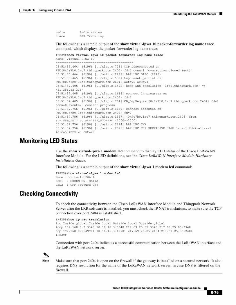
Chapter 6 Configuring Virtual-LPWA Monitoring the LoRaWAN Modem
radio Radio statustrace LRR Trace log
The following is a sample output of the show virtual-lpwa 10 packet-forwarder log name trace command, which displays the packet-forwarder log name trace:
IR829#show virtual-lpwa 10 packet-forwarder log name traceName: Virtual-LPWA 10 ==========================================05:51:35.464 (6196) [../xlap.c:726] TCP Disconnected on RTU(0x7e7b0,lrc7.thingpark.com,2404) fd=7 conn=1 'connection closed (eot)'05:51:35.464 (6196) [../main.c:2299] LAP LRC DISC (2648)05:51:35.465 (6196) [../xlap.c:553] Lap reset partial on RTU(0x7e7b0,lrc7.thingpark.com,2404) outq=0 ackq=305:51:37.405 (6196) [../xlap.c:1492] keep DNS resolution 'lrc7.thingpark.com' => '51.255.52.229'05:51:37.405 (6196) [../xlap.c:1614] connect in progress on RTU(0x7e7b0,lrc7.thingpark.com,2404) fd=705:51:37.405 (6196) [../xlap.c:784] CB_LapRequest(0x7e7b0,lrc7.thingpark.com,2404) fd=7 conn=0 events=0 connect progress05:51:37.756 (6196) [../xlap.c:1139] connect accepted on RTU(0x7e7b0,lrc7.thingpark.com,2404) fd=705:51:37.756 (6196) [../xlap.c:1397] (0x7e7b0,lrc7.thingpark.com,2404) from st='SSP_INIT'to st='SSP_STOPPED'(1000->2000)05:51:37.756 (6196) [../main.c:2294] LAP LRC CNX05:51:37.756 (6196) [../main.c:2075] LAP LRC TCP KEEPALIVE HIGH lrc=-1 fd=7 alive=1 idle=5 intvl=5 cnt=20
Monitoring LED StatusUse the show virtual-lpwa 1 modem led command to display LED status of the Cisco LoRaWAN Interface Module. For the LED definitions, see the Cisco LoRaWAN Interface Module Hardware Installation Guide.
The following is a sample output of the show virtual-lpwa 1 modem led command:
IR829#show virtual-lpwa 1 modem ledName : Virtual-LPWA 1 LED1 : GREEN ON, SolidLED2 : OFF !Future use
Checking ConnectivityTo check the connectivity between the Cisco LoRaWAN Interface Module and Thingpark Network Server after the LRR software is installed, you must check the IP NAT translations, to make sure the TCP connection over port 2404 is established.
IR829#show ip nat translationPro Inside global Inside local Outside local Outside globalicmp 192.168.0.2:3348 10.16.16.3:3348 217.69.25.85:3348 217.69.25.85:3348tcp 192.168.0.2:49901 10.16.16.3:49901 217.69.25.85:2404 217.69.25.85:2404IR829#
Connection with port 2404 indicates a successful communication between the LoRaWAN interface and the LoRaWAN network server.
Note Make sure that port 2404 is open on the firewall if the gateway is installed on a secured network. It also requires DNS resolution for the name of the LoRaWAN network server, in case DNS is filtered on the firewall.
6-76Cisco IR800 Integrated Services Router Software Configuration Guide

Chapter 6 Configuring Virtual-LPWA Debugging the LoRaWAN Modem
Debugging the LoRaWAN ModemOn the IR800 series, beginning in privileged EXEC mode, use these commands to debug the Cisco LoRaWAN Interface Module.
Command Purpose
debug vlpwa all Enables all vlpwa debug messages.
undebug vlpwa all Disables all vlpwa debug messages.
debug vlpwa [decode | detail | errors | memory | raw | registry | session | timers | trace]
Enables the following vlpwa debug messages:
• decode—Decoded packet information.
• detail—Detailed trace information.
• errors—Errors.
• memory—Memory information.
• raw—Raw packet information.
• registry—Registry information.
• session—Session information.
• timers—Timers information.
• trace—Trace information.
6-77Cisco IR800 Integrated Services Router Software Configuration Guide
Cisco IR800 Integr
C H A P T E R 7
AlarmsFinding Feature InformationYour software release may not support all the features documented in this chapter. For the latest feature information and caveats, see the release notes for your platform and software release.
Use Cisco Feature Navigator to find information about platform support and Cisco software image support. To access Cisco Feature Navigator, go to:
http://www.cisco.com/go/cfn.
An account on Cisco.com is not required.
Note This chapter provides instructions for configuring the alarms on the IR809. The IR829 does not have an alarm port.
Information About Alarms If the conditions present on the IR809 do not match the set parameters, the IR809 software triggers an alarm or a system message. By default, the IR809 software sends the system messages to a system message logging facility, or a syslog facility. You can also configure the IR809 to send Simple Network Management Protocol (SNMP) traps to an SNMP server.
Alarm PortThe Cisco IR800 has alarm ports as shown in Cisco IR809 Front Panel. Additional details and instructions about connecting the alarm ports are found in the IR809 Hardware Configuration Guide and the Getting Started and Product Document of Compliance for the Cisco IR809 Integrated Services Router.
7-78ated Services Router Software Configuration Guide

Chapter 7 Alarms Alarm Conditions
Alarm ConditionsThere are two conditions that generate an alarm:
• If the alarm is connected to a door switch or an enclosure and detects a door opening.
– This is an external alarm and requires wiring. See the IR809 Hardware Installation Guide.
• When the internal temperature is too high.
– This is an internal alarm, no wiring required.
Note Prior to IOS 15.6(1)T, the default thresholds were set too low: minor alarm if exceeding 60°C, or major alarm if exceeding 75°C or too low of a cold temperature threshold, less than -25°C. After OS 15.6(1)T, the default values were changed to 84C (Minor) and 93C (Major) .
When either condition is met, the alarm LED turns red, and a syslog message and SNMP trap is triggered if configured.
SNMP Traps
SNMP is an application-layer protocol that provides a message format for communication between managers and agents. The SNMP system consists of an SNMP manager, an SNMP agent, and a management information base (MIB).
The snmp-server enable traps command can be changed so that the user can send alarm traps to an SNMP server. You can use alarm profiles to set environmental or port status alarm conditions to send SNMP alarm traps.
Syslog Messages
You can use alarm profiles to send system messages to a syslog server.
Configuration CommandsYou can set the alarm severity to critical, major, minor, or none. The severity is included in the alarm message when the alarm is triggered.
To configure and show alarms on the IR809, use the Command Line Interface (CLI).
Command Purpose
configure terminal Enters global configuration mode.
alarm contact contact-number description string (Optional) Configures a description for the alarm contact number.
• The contact-number value is from 1 to 4.
• The description string is up to 80 alphanumeric characters in length and is included in any generated system messages.
7-79Cisco IR800 Integrated Services Router Software Configuration Guide
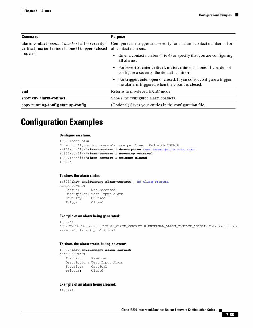
Chapter 7 Alarms Configuration Examples
Configuration ExamplesConfigure an alarm.IR809#conf termEnter configuration commands, one per line. End with CNTL/Z.IR809(config)#alarm-contact 1 description Your Descriptive Text HereIR809(config)#alarm-contact 1 severity critical IR809(config)#alarm-contact 1 trigger closed IR809#
To show the alarm status:IR809#show environment alarm-contact ! No Alarm PresentALARM CONTACT Status: Not Asserted Description: Test Input Alarm Severity: Critical Trigger: Closed
Example of an alarm being generated:IR809#! *Nov 27 14:54:52.573: %IR800_ALARM_CONTACT-0-EXTERNAL_ALARM_CONTACT_ASSERT: External alarm asserted, Severity: Critical
To show the alarm status during an event:IR809#show environment alarm-contactALARM CONTACT Status: Asserted Description: Test Input Alarm Severity: Critical Trigger: Closed
Example of an alarm being cleared:IR809#!
alarm contact {contact-number | all} {severity { critical | major | minor | none} | trigger {closed | open}}
Configures the trigger and severity for an alarm contact number or for all contact numbers.
• Enter a contact number (1 to 4) or specify that you are configuring all alarms.
• For severity, enter critical, major, minor or none. If you do not configure a severity, the default is minor.
• For trigger, enter open or closed. If you do not configure a trigger, the alarm is triggered when the circuit is closed.
end Returns to privileged EXEC mode.
show env alarm-contact Shows the configured alarm contacts.
copy running-config startup-config (Optional) Saves your entries in the configuration file.
Command Purpose
7-80Cisco IR800 Integrated Services Router Software Configuration Guide
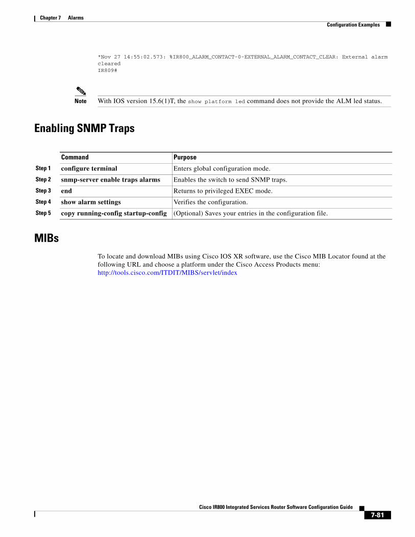
Chapter 7 Alarms Configuration Examples
*Nov 27 14:55:02.573: %IR800_ALARM_CONTACT-0-EXTERNAL_ALARM_CONTACT_CLEAR: External alarm clearedIR809#
Note With IOS version 15.6(1)T, the show platform led command does not provide the ALM led status.
Enabling SNMP Traps
MIBsTo locate and download MIBs using Cisco IOS XR software, use the Cisco MIB Locator found at the following URL and choose a platform under the Cisco Access Products menu: http://tools.cisco.com/ITDIT/MIBS/servlet/index
Command Purpose
Step 1 configure terminal Enters global configuration mode.
Step 2 snmp-server enable traps alarms Enables the switch to send SNMP traps.
Step 3 end Returns to privileged EXEC mode.
Step 4 show alarm settings Verifies the configuration.
Step 5 copy running-config startup-config (Optional) Saves your entries in the configuration file.
7-81Cisco IR800 Integrated Services Router Software Configuration Guide
Cisco IR800 Integr
C H A P T E R 8
Guest Operating System (Guest OS) Installation and ConfigurationThis chapter details Guest Operating System (Guest OS) installation for the Cisco IR800.
This chapter contains the following sections:
• Guest Operating System Overview, page 8-82
• Prerequisites, page 8-83
• Guidelines and Limitations, page 8-83
• Installation and Upgrade, page 8-84
• Configuring Cisco IOS, page 8-85
• Configuring Guest OS, page 8-88
• Configuring Network Address Translation (NAT), page 8-90
• Troubleshooting, page 8-94
• Related Documentation, page 8-95
Guest Operating System OverviewThe IR800 supports a Hypervisor architecture to support user-specified operating systems within an independent Virtual Machine (VM).
When you install the IR800 IOS software bundle (image) on the router, the image automatically installs the supported Guest OS (Cisco IOS and Linux OS) instance(s). You can use the Linux Guest OS running on a VM on the IR800 to run applications.
The following example shows connectivity of Guest OS and Cisco IOS. A virtual interface managed by Cisco IOS provides network connectivity to Guest OS. Cisco IOS forwards traffic from Guest OS through regular IP forwarding mechanisms.
8-82ated Services Router Software Configuration Guide

Chapter 8 Guest Operating System (Guest OS) Installation and Configuration Prerequisites
Figure 8-1 Connectivity Between Cisco IOS and Guest OS
In this example, number 1 is the interface being used on the router and number 2 is the interface on the Linux OS.
For the Cisco IR809, 1 is Gigabit Ethernet 2 and 2 is Eth 0.
For the Cisco IR829, 1 is Gigabit Ethernet 5 and 2 is Eth 0
Additionally, the Virtual Machine Linux has a virtual console, and two virtual serial ports.
Prerequisites• Router must be running Cisco IOS 15.6(2)T or higher.
Note The IOXVM image delivered in the IOS bundle may not be the most recent. Check Cisco.com for the latest version at:http://software.cisco.com/download/cart.html?imageGuId=F51FECDC2E4FE5814715000B44317E5500EB47C5&i=rs
Guidelines and Limitations• The bundled Guest OS delivered with 15.6(2)T is based on Yocto Linux Project 1.8 Reference
Distro, with basic services enabled:
– IPv4/IPv6
– DHCP
– NTP
– AAA (Radius)
– Python 2.7
– Basic debugging tools (tcpdump, top, etc)
– bash
• Serial relay for Guest OS control of the Serial Interface
– Async 0 and Async 1 respectively reserve line 1/5 and 1/6 to relay serial data to the corresponding Guest OS /dev/ttyS1 and /dev/ttyS2
8-83Cisco IR800 Integrated Services Router Software Configuration Guide
Chapter 8 Guest Operating System (Guest OS) Installation and Configuration Default Settings
Note Prior to 15.6(3)M, Serial Interface parameters needed to be set through IOS. 15.6(3)M allows setting the parameters directly from the Guest OS, through standard Linux commands.
• You must configure Cisco IOS to provide Guest OS Connectivity.
Note There is an IOXVM image more recent than IOS bundle, (IOXVM 1.0.4) available on Cisco.com
Default Settings The bundled Linux Guest OS:
• Uses DHCP to acquire the IPv4 address.
• Does not have a default root password.
• Use IPv6 stateless auto-configuration to get an IPv6 address
Note Without an IPv6 address set on both GXX and ETH0, the Guest OS will never get displayed as registered under show iox host list detail. GXX is defined as GI5 on the IR829 and GI2 on the IR809.
Installation and UpgradeBy default, IR800s ship with a software bundle that includes the latest versions of all of the required images such as Cisco IOS, Guest OS, and Hypervisor.
Note Before performing a bundle installation, shutdown the Guest OS. Performing a bundle installation on a device with an active Guest OS may result in it not functioning upon reboot.
Use the following procedure to upgrade your router to the latest software bundle. It can take several minutes for the router to upgrade and install all of the images (Hypervisor, Cisco IOS, and Guest OS).
DETAILED STEPS
Step 1 Copy the bundle image to the IR800 IOS flash partition using scp or sftp.
Example bundle name: ir800-universalk9-bundle.SPA.<VERSION>
Step 2 Enter the following commands at the IR800 prompt:
8-84Cisco IR800 Integrated Services Router Software Configuration Guide
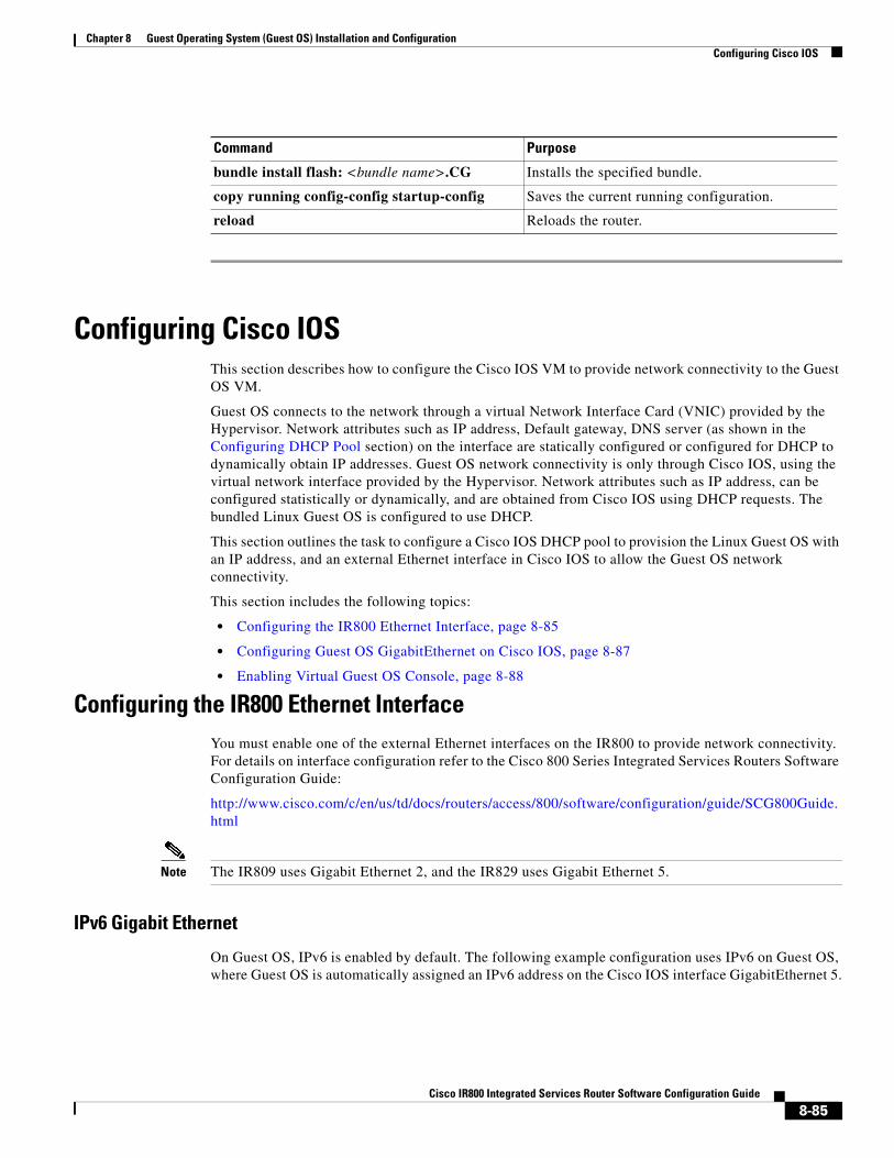
Chapter 8 Guest Operating System (Guest OS) Installation and Configuration Configuring Cisco IOS
Configuring Cisco IOSThis section describes how to configure the Cisco IOS VM to provide network connectivity to the Guest OS VM.
Guest OS connects to the network through a virtual Network Interface Card (VNIC) provided by the Hypervisor. Network attributes such as IP address, Default gateway, DNS server (as shown in the Configuring DHCP Pool section) on the interface are statically configured or configured for DHCP to dynamically obtain IP addresses. Guest OS network connectivity is only through Cisco IOS, using the virtual network interface provided by the Hypervisor. Network attributes such as IP address, can be configured statistically or dynamically, and are obtained from Cisco IOS using DHCP requests. The bundled Linux Guest OS is configured to use DHCP.
This section outlines the task to configure a Cisco IOS DHCP pool to provision the Linux Guest OS with an IP address, and an external Ethernet interface in Cisco IOS to allow the Guest OS network connectivity.
This section includes the following topics:
• Configuring the IR800 Ethernet Interface, page 8-85
• Configuring Guest OS GigabitEthernet on Cisco IOS, page 8-87
• Enabling Virtual Guest OS Console, page 8-88
Configuring the IR800 Ethernet InterfaceYou must enable one of the external Ethernet interfaces on the IR800 to provide network connectivity. For details on interface configuration refer to the Cisco 800 Series Integrated Services Routers Software Configuration Guide:
http://www.cisco.com/c/en/us/td/docs/routers/access/800/software/configuration/guide/SCG800Guide.html
Note The IR809 uses Gigabit Ethernet 2, and the IR829 uses Gigabit Ethernet 5.
IPv6 Gigabit Ethernet
On Guest OS, IPv6 is enabled by default. The following example configuration uses IPv6 on Guest OS, where Guest OS is automatically assigned an IPv6 address on the Cisco IOS interface GigabitEthernet 5.
Command Purpose
bundle install flash: <bundle name>.CG Installs the specified bundle.
copy running config-config startup-config Saves the current running configuration.
reload Reloads the router.
8-85Cisco IR800 Integrated Services Router Software Configuration Guide

Chapter 8 Guest Operating System (Guest OS) Installation and Configuration Configuring Cisco IOS
Enabling IPv4 Gigabit Ethernet
Note Configuring an IPv4 address on a Gigabit port is not a required part of configuring the Guest OS. However, IOS interfaces must be set to enable external devices to communicate with the Guest-OS through IOS.
To enable an external Gigabit Ethernet IPv4 interface on the IR800 to provide network connectivity, enter the following commands:
Configuring DHCP Pool
To configure a local DHCP pool, enter the following commands, one per line:
Note The subnet used for the local DHCP pool must be reachable externally. If you cannot allocate the whole subnet to Guest OS, use a NAT-based configuration. See Configuring Network Address Translation (NAT).
Command Purpose
ipv6 unicast-routing Enables unicast routing.
ipv6 cef Enables cef.
interface GigabitEthernet 5 Set the internal virtual interface that connects to the Linux Guest OS.
ipv6 address autoconfig Sets the IPv6 address.
ipv6 enable Enables IPv6.
Command Purpose
config terminal Enters global configuration mode.
interface gig 0 Configures an IPv4 address on Gigabit Ethernet interface 0, and enters interface configuration mode.
ip address 9.1.2.1 255.255.255.0 Sets the IP address and subnet mask for Gigabit Ethernet interface 0.
no shutdown Enables the Gigabit Ethernet interface.
Command Purpose
config terminal Enters global configuration mode.
ip dhcp pool gospool Names the local DHCP pool.
network 9.1.2.0 255.255.255.0 Sets the network address.
default-router 9.1.2.1 Sets the router address.
8-86Cisco IR800 Integrated Services Router Software Configuration Guide
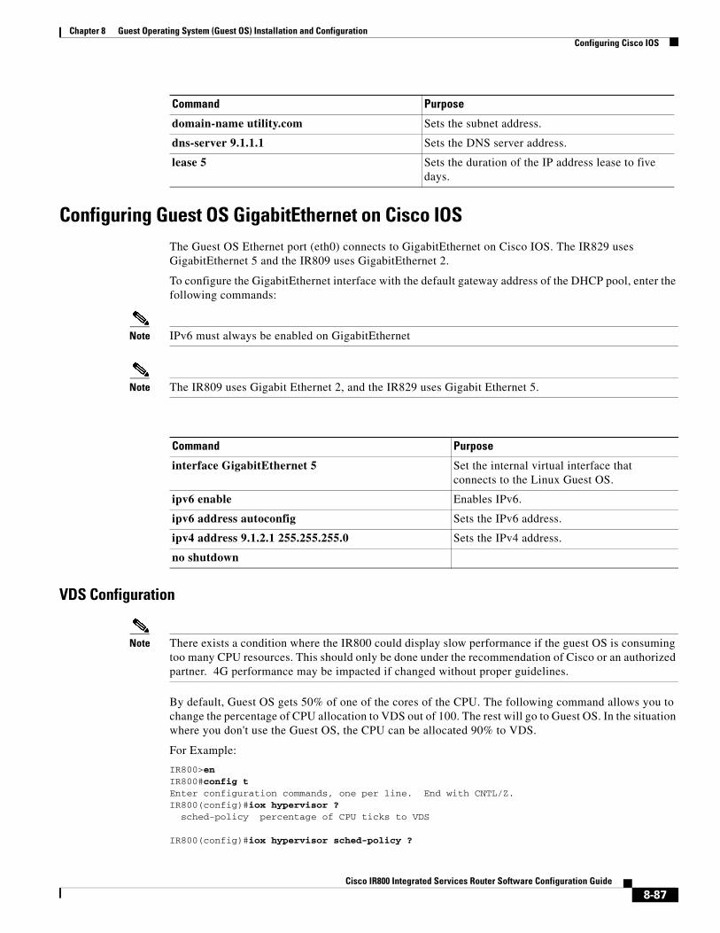
Chapter 8 Guest Operating System (Guest OS) Installation and Configuration Configuring Cisco IOS
Configuring Guest OS GigabitEthernet on Cisco IOSThe Guest OS Ethernet port (eth0) connects to GigabitEthernet on Cisco IOS. The IR829 uses GigabitEthernet 5 and the IR809 uses GigabitEthernet 2.
To configure the GigabitEthernet interface with the default gateway address of the DHCP pool, enter the following commands:
Note IPv6 must always be enabled on GigabitEthernet
Note The IR809 uses Gigabit Ethernet 2, and the IR829 uses Gigabit Ethernet 5.
VDS Configuration
Note There exists a condition where the IR800 could display slow performance if the guest OS is consuming too many CPU resources. This should only be done under the recommendation of Cisco or an authorized partner. 4G performance may be impacted if changed without proper guidelines.
By default, Guest OS gets 50% of one of the cores of the CPU. The following command allows you to change the percentage of CPU allocation to VDS out of 100. The rest will go to Guest OS. In the situation where you don't use the Guest OS, the CPU can be allocated 90% to VDS.
For Example:
IR800>enIR800#config tEnter configuration commands, one per line. End with CNTL/Z.IR800(config)#iox hypervisor ? sched-policy percentage of CPU ticks to VDS
IR800(config)#iox hypervisor sched-policy ?
domain-name utility.com Sets the subnet address.
dns-server 9.1.1.1 Sets the DNS server address.
lease 5 Sets the duration of the IP address lease to five days.
Command Purpose
Command Purpose
interface GigabitEthernet 5 Set the internal virtual interface that connects to the Linux Guest OS.
ipv6 enable Enables IPv6.
ipv6 address autoconfig Sets the IPv6 address.
ipv4 address 9.1.2.1 255.255.255.0 Sets the IPv4 address.
no shutdown
8-87Cisco IR800 Integrated Services Router Software Configuration Guide

Chapter 8 Guest Operating System (Guest OS) Installation and Configuration Configuring Guest OS
10 VDS 10% Guest OS 90% 20 VDS 20% Guest OS 80% 30 VDS 30% Guest OS 70% 40 VDS 40% Guest OS 60% 50 VDS 50% Guest OS 50% 60 VDS 60% Guest OS 40% 70 VDS 70% Guest OS 30% 80 VDS 80% Guest OS 20% 90 VDS 90% Guest OS 10%
IR800(config)#iox hypervisor sched-policy 90
Enabling Virtual Guest OS Console For heightened security, Guest OS console is disabled by default. To enable Guest OS console, enter the following commands:
Configuring Guest OSThis section describes how to set the root password for Guest OS and enable SSH access. By default, SSH is disabled in Guest OS, this section describes the steps to reverse-Telnet into Guest OS, and enable SSH access.
Starting Guest OS
By default, Guest OS starts after installation. To manually start the Guest OS, enter the following commands:
During start up, Guest OS sends a DHCP request and is assigned an IP address from the local DHCP pool and an IPv6 address through IPv6 stateless auto-configuration. Guest OS is then configured with a hostname and sync time from IOS.
Note It can take a few minutes for the Guest OS to start.
Command Purpose
config terminal Enters global configuration mode.
line 1/4 Specifies line 1/4 for configuration and enters line configuration collection mode.
transport input all Defines which protocols to use to connect to a specific line of the router.
Command Purpose
show iox host list detail Displays OS: RUNNING if Guest OS is already running. If it is, go to Accessing Virtual Guest OS Console.
guest-os 1 start Starts Guest OS.
8-88Cisco IR800 Integrated Services Router Software Configuration Guide
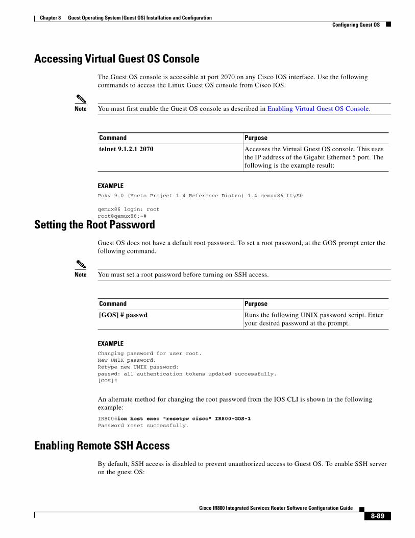
Chapter 8 Guest Operating System (Guest OS) Installation and Configuration Configuring Guest OS
Accessing Virtual Guest OS Console The Guest OS console is accessible at port 2070 on any Cisco IOS interface. Use the following commands to access the Linux Guest OS console from Cisco IOS.
Note You must first enable the Guest OS console as described in Enabling Virtual Guest OS Console.
EXAMPLEPoky 9.0 (Yocto Project 1.4 Reference Distro) 1.4 qemux86 ttyS0
qemux86 login: rootroot@qemux86:~#
Setting the Root PasswordGuest OS does not have a default root password. To set a root password, at the GOS prompt enter the following command.
Note You must set a root password before turning on SSH access.
EXAMPLEChanging password for user root.New UNIX password:Retype new UNIX password:passwd: all authentication tokens updated successfully.[GOS]#
An alternate method for changing the root password from the IOS CLI is shown in the following example:
IR800#iox host exec "resetpw cisco" IR800-GOS-1 Password reset successfully.
Enabling Remote SSH AccessBy default, SSH access is disabled to prevent unauthorized access to Guest OS. To enable SSH server on the guest OS:
Command Purpose
telnet 9.1.2.1 2070 Accesses the Virtual Guest OS console. This uses the IP address of the Gigabit Ethernet 5 port. The following is the example result:
Command Purpose
[GOS] # passwd Runs the following UNIX password script. Enter your desired password at the prompt.
8-89Cisco IR800 Integrated Services Router Software Configuration Guide
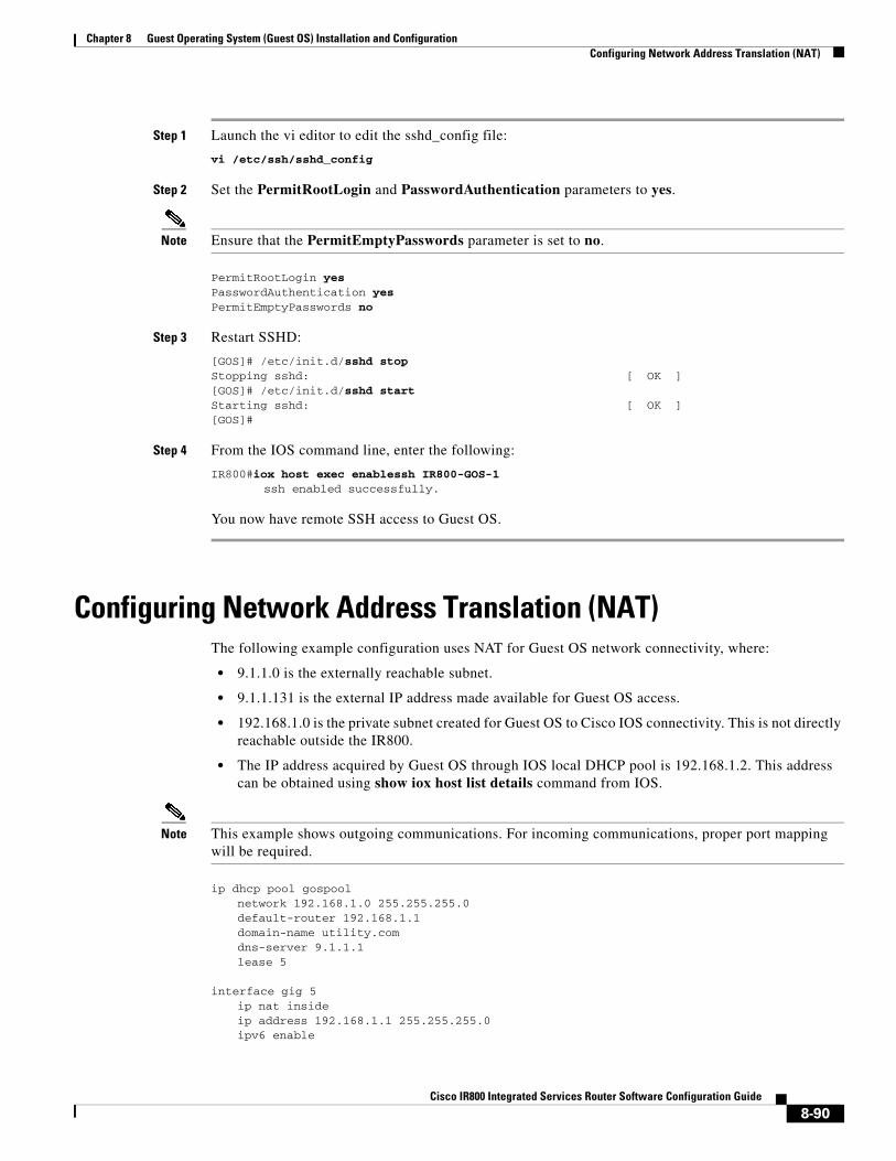
Chapter 8 Guest Operating System (Guest OS) Installation and Configuration Configuring Network Address Translation (NAT)
Step 1 Launch the vi editor to edit the sshd_config file:
vi /etc/ssh/sshd_config
Step 2 Set the PermitRootLogin and PasswordAuthentication parameters to yes.
Note Ensure that the PermitEmptyPasswords parameter is set to no.
PermitRootLogin yes PasswordAuthentication yes PermitEmptyPasswords no
Step 3 Restart SSHD:
[GOS]# /etc/init.d/sshd stopStopping sshd: [ OK ][GOS]# /etc/init.d/sshd startStarting sshd: [ OK ][GOS]#
Step 4 From the IOS command line, enter the following:
IR800#iox host exec enablessh IR800-GOS-1 ssh enabled successfully.
You now have remote SSH access to Guest OS.
Configuring Network Address Translation (NAT)The following example configuration uses NAT for Guest OS network connectivity, where:
• 9.1.1.0 is the externally reachable subnet.
• 9.1.1.131 is the external IP address made available for Guest OS access.
• 192.168.1.0 is the private subnet created for Guest OS to Cisco IOS connectivity. This is not directly reachable outside the IR800.
• The IP address acquired by Guest OS through IOS local DHCP pool is 192.168.1.2. This address can be obtained using show iox host list details command from IOS.
Note This example shows outgoing communications. For incoming communications, proper port mapping will be required.
ip dhcp pool gospoolnetwork 192.168.1.0 255.255.255.0default-router 192.168.1.1domain-name utility.comdns-server 9.1.1.1lease 5
interface gig 5ip nat insideip address 192.168.1.1 255.255.255.0ipv6 enable
8-90Cisco IR800 Integrated Services Router Software Configuration Guide

Chapter 8 Guest Operating System (Guest OS) Installation and Configuration Configuring Network Address Translation (NAT)
no shutdown interface gig 0
ip nat outsideip address 9.1.1.5 255.255.255.0no shutdown
ip nat inside source static 192.168.1.2 9.1.1.131
! End of configuration
IR800#sh ip nat transPro Inside global Inside local Outside local Outside globaltcp 9.1.1.131:22 192.168.1.2:22 9.1.1.3:53649 9.1.1.3:53649tcp 9.1.1.131:60100 192.168.1.2:60100 9.1.1.3:22 9.1.1.3:22--- 9.1.1.131 192.168.1.2 --- ---
For more information about NAT, please see the Configuring Network Address Translation: Getting Started Guide.
http://www.cisco.com/c/en/us/support/docs/ip/network-address-translation-nat/13772-12.html
IR800 Guest-OS USB Access from IOSIR800 IOS releases don’t support an external USB storage directly accessible from IOS. However, it is possible to mount an external USB storage on the IR800 Guest-OS, then use it from IOS through SCP
Plug an external USB storage, wait for its recognition.
Edit “/etc/fstab” to add the new sdc1 drive, then mount it.
root@IR800-GOS-1:# vi /etc/fstabRootfs / auto defaults 1 1Proc /proc proc defaults 0 0devpts /dev/pts devpts mode=0620,gid=5 0 0usbdevfs /proc/bus/usb usbdevfs noauto 0 0tmpfs /var/volatile tmpfs defaults 0 0tmpfs /media/ram tmpfs defaults 0 0/dev/sdc1 /mnt/sdc1 auto defaults 0 0
Example of no USB storage recognizedroot@IR800-GOS-1:~# ls /dev/sd*/dev/sda /dev/sda1 /dev/sdb
Example of USB storage recognizedroot@IR800-GOS-1:~# ls /dev/sd*/dev/sda /dev/sda1 /dev/sdb /dev/sdc /dev/sdc1
root@IR800-GOS-1:/etc# fdisk -l /dev/sdc
Disk /dev/sdc: 1993 MB, 1993342976 bytes, 3893248 sectorsUnits = sectors of 1 * 512 = 512 bytesSector size (logical/physical): 512 bytes / 512 bytesI/O size (minimum/optimal): 512 bytes / 512 bytesDisk identifier: 0x00000000
Device Boot Start End Blocks Id System/dev/sdc1 2 3893247 1946623 b W95 FAT32
8-91Cisco IR800 Integrated Services Router Software Configuration Guide
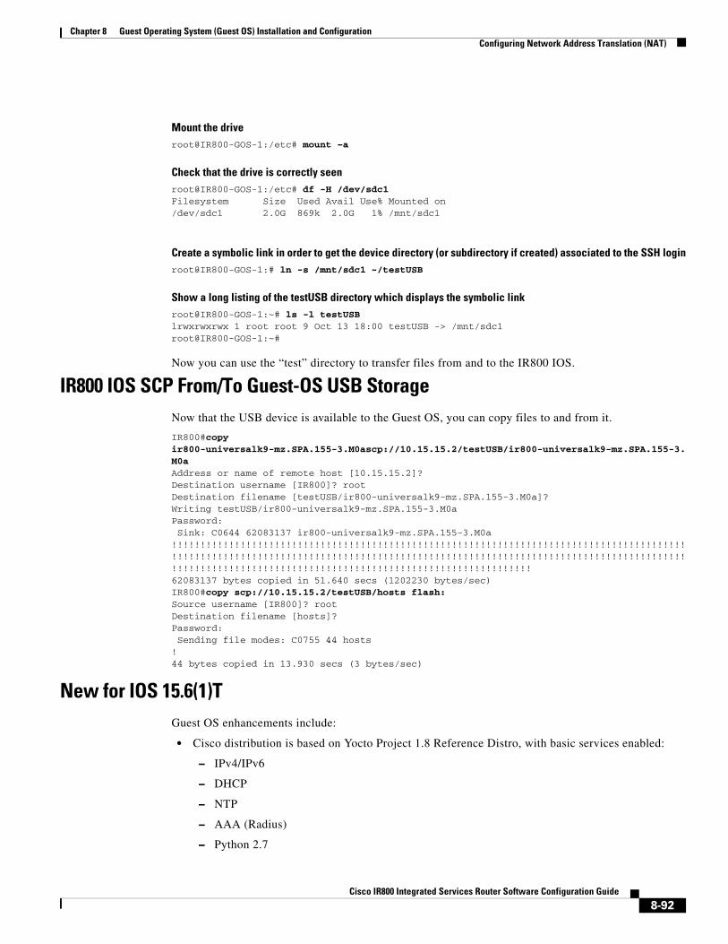
Chapter 8 Guest Operating System (Guest OS) Installation and Configuration Configuring Network Address Translation (NAT)
Mount the driveroot@IR800-GOS-1:/etc# mount –a
Check that the drive is correctly seenroot@IR800-GOS-1:/etc# df -H /dev/sdc1Filesystem Size Used Avail Use% Mounted on/dev/sdc1 2.0G 869k 2.0G 1% /mnt/sdc1
Create a symbolic link in order to get the device directory (or subdirectory if created) associated to the SSH loginroot@IR800-GOS-1:# ln -s /mnt/sdc1 ~/testUSB
Show a long listing of the testUSB directory which displays the symbolic linkroot@IR800-GOS-1:~# ls -l testUSBlrwxrwxrwx 1 root root 9 Oct 13 18:00 testUSB -> /mnt/sdc1root@IR800-GOS-1:~#
Now you can use the “test” directory to transfer files from and to the IR800 IOS.
IR800 IOS SCP From/To Guest-OS USB StorageNow that the USB device is available to the Guest OS, you can copy files to and from it.
IR800#copy ir800-universalk9-mz.SPA.155-3.M0ascp://10.15.15.2/testUSB/ir800-universalk9-mz.SPA.155-3.M0aAddress or name of remote host [10.15.15.2]? Destination username [IR800]? rootDestination filename [testUSB/ir800-universalk9-mz.SPA.155-3.M0a]? Writing testUSB/ir800-universalk9-mz.SPA.155-3.M0a Password: Sink: C0644 62083137 ir800-universalk9-mz.SPA.155-3.M0a!!!!!!!!!!!!!!!!!!!!!!!!!!!!!!!!!!!!!!!!!!!!!!!!!!!!!!!!!!!!!!!!!!!!!!!!!!!!!!!!!!!!!!!!!!!!!!!!!!!!!!!!!!!!!!!!!!!!!!!!!!!!!!!!!!!!!!!!!!!!!!!!!!!!!!!!!!!!!!!!!!!!!!!!!!!!!!!!!!!!!!!!!!!!!!!!!!!!!!!!!!!!!!!!!!!!!!!!!!!!!!!!!!!!!!!!!!!!!!!!!!!62083137 bytes copied in 51.640 secs (1202230 bytes/sec)IR800#copy scp://10.15.15.2/testUSB/hosts flash:Source username [IR800]? rootDestination filename [hosts]? Password: Sending file modes: C0755 44 hosts!44 bytes copied in 13.930 secs (3 bytes/sec)
New for IOS 15.6(1)TGuest OS enhancements include:
• Cisco distribution is based on Yocto Project 1.8 Reference Distro, with basic services enabled:
– IPv4/IPv6
– DHCP
– NTP
– AAA (Radius)
– Python 2.7
8-92Cisco IR800 Integrated Services Router Software Configuration Guide

Chapter 8 Guest Operating System (Guest OS) Installation and Configuration Configuring Network Address Translation (NAT)
– Basic debugging tools (tcpdump, top, etc)
– bash
• Serial relay for Guest OS control of the Serial Interface
– Async 0 and Async 1 respectively reserve line 1/5 and 1/6 to relay serial data to the corresponding Guest OS /dev/ttyS1 and /dev/ttyS2
New for IOS 15.6(3)M
USB Support
Previous to 15.6(3)M, the USB devices, which are connected to external USB port could be emulated on the Guest OS through OHCI mode only. With this feature hypervisor will be enhanced to support EHCI emulation to Guest OS.
Serial Device Configuration
Previously, the Guest OS could not configure the physical serial port on the device. The serial port configuration (e.g. baud rate change) of the serial port needed to be done in IOS.
With 15.6(3)M, hypervisor and IOS are enhanced so that if the Guest OS changes the virtual serial port configuration, it notifies IOS, and IOS applies the configuration to the physical serial port.
Command line changes consist of the following:
A new option is appended to allow the baudrate, databits, stopbits and parity propagation from Guest OS. If "propagation" is present, the control parameters will be passed from Guest OS to IOS physical port. Otherwise it functions as before.
The serial port control parameters included in the propagation are: baudrate, databits, stopbits and parity.
relay line <linex> <liney> [propagation]
Serial Relay Configuration
IR800#conf termEnter configuration commands, one per line. End with CNTL/Z.IR800(config)#inter asyn 0IR800(config-if)# encap relay-lineIR800(config-if)# end
IR800(config)# line 1IR800(config-line)# transport input allIR800(config-line)#IR800(config)# relay line 1 1/5 propagation
IR800# show line 1/5
Guest OS output for /dev/tty
GOS is installed through the IOX bundle install process and can be started/stopped and upgraded from IOS CLI
Verification for digitally-signed GOS image distributed via Cisco DevNet must be installed using the guest-os image install command only.
8-93Cisco IR800 Integrated Services Router Software Configuration Guide

Chapter 8 Guest Operating System (Guest OS) Installation and Configuration Troubleshooting
Memory Allocation Optimization
Improvements have been made in the memory allocation optimization between VDS, IOS and GOS on the IR800. Previously, the 2GB RAM was allocated as follows:
• VDS: 512MB
• IOS: 512MB
• Guest OS: 725MB
• Remainder: used by hypervisor (e.g. device share memory)
Now with optimization, the VDS memory was reduced to give at least 1GB to the Guest OS.
TroubleshootingTo determine common causes of configuration failure, enter the following commands:
Command Purpose
Guest OS Commands:
ifconfig eth0 Checks if Guest OS is assigned an IP address. The following is example output:
eth0 Link encap:Ethernet HWaddr 02:00:03:f1:cd:05inet addr:9.1.2.2 Bcast:0.0.0.0 Mask:255.255.255.248UP BROADCAST RUNNING MULTICAST MTU:1500 Metric:1RX packets:2 errors:0 dropped:0 overruns:0 frame:0TX packets:5 errors:0 dropped:0 overruns:0 carrier:0collisions:0 txqueuelen:1000RX bytes:684 (684.0 B) TX bytes:894 (894.0 B)
[GOS]#
netstat -r Displays the Guest OS route table. The following is example output:
Kernel IP routing tableDestination Gateway Genmask Flags MSS Window irtt Ifacedefault 9.1.2.1 0.0.0.0 UG 0 0 0 eth09.1.2.0 * 255.255.255.0 U 0 0 0 eth0[GOS]#
IOS Commands:
show ip arp Verifies that Cisco IOS learned Guest OS ARP mapping.The following is example output:
Protocol Address Age (min) Hardware Addr Type InterfaceInternet 9.1.1.1 - 0022.bdef.c562 ARPA GigabitEthernet0Internet 9.1.2.1 - 0022.bdef.c569 ARPA GigabitEthernet2Internet 9.1.2.2 112 0022.bdef.c56d ARPA GigabitEthernet2IR800#
show ipv6 neighbor Verifies that Cisco IOS learned Guest OS IPv6 neighbor address.The following is example output:
IPv6 Address Age Link-layer Addr State InterfaceFE80::1FF:FE90:8B05 0 0200.0190.8b05 REACH Gi2
show platform guest-os Guest-OS started
8-94Cisco IR800 Integrated Services Router Software Configuration Guide

Chapter 8 Guest Operating System (Guest OS) Installation and Configuration Related Documentation
Checking ConnectivityUse standard Linux tools (for example, ping and traceroute) to check Guest OS connectivity.
Related Documentation
Note While some of these references do not apply directly to the Cisco IR800 series of Industrial Routers, they may serve as a source of addition information.
For information on supporting systems referenced in this guide, see the following documentation on Cisco.com:
Guest OS status:Installation: Cisco-GOS,version-1.28State: RUNNINGIR800#
show iox host list detail Guest-OS started, normal operation
IOX Server is running. Process ID: 319Count of hosts registered: 1
Host registered:=============== IOX Server Address: FE80::76A2:E6FF:FEFD:6A6C; Port: 22222
Link Local Address of Host: FE80::1FF:FE90:8B05 IPV4 Address of Host: 10.15.15.2 IPV6 Address of Host: fe80::1ff:fe90:8b05 Client Version: 0.1 Session ID: 1 OS Nodename: IR809-GOS-1 Host Hardware Vendor: Cisco Systems, Inc. Host Hardware Version: 1.0 Host Card Type: not implemented Host OS Version: 1.28 OS status: RUNNING
Interface Hardware Vendor: None Interface Hardware Version: None Interface Card Type: None
Applications Registered: =======================
Count of applications registered by this host: 0IR800#
show iox host list detail Guest-OS started but no IPv6 address set-up on the GI2 interface
IOX Server is running. Process ID: 319Count of hosts registered: 0 IOX Server Address: 0.0.0.0; Port: 22222
IR800#
Command Purpose
8-95Cisco IR800 Integrated Services Router Software Configuration Guide
Chapter 8 Guest Operating System (Guest OS) Installation and Configuration Related Documentation
DevNet documentation on IOx. Provides an overview as well as details on the IR800 series by scrolling down the left hand side:
https://developer.cisco.com/site/iox/documents/developer-guide/?ref=overview
Cisco Fog Director Reference Guide:
http://www.cisco.com/c/en/us/support/cloud-systems-management/fog-director/products-technical-reference-list.html
IOx Reference Guide:
http://www.cisco.com/c/en/us/support/cloud-systems-management/iox/products-technical-reference-list.html
Release Notes:
http://www.cisco.com/c/en/us/support/cloud-systems-management/fog-director/products-release-notes-list.html
http://www.cisco.com/c/en/us/support/cloud-systems-management/iox/products-release-notes-list.html
Other Sources:
Cisco IOS IP Application Services Command Reference
IPv6 configuration manual
8-96Cisco IR800 Integrated Services Router Software Configuration Guide
Cisco IR800 Integr
C H A P T E R 9
WAN MonitoringThis chapter describes the WAN Monitoring software, WANMon, as implemented in Cisco IOS deployments. WANMon monitors the backhaul and initiates recovery actions on link failure.
This guide includes the following sections:
• Information About WANMon, page 9-97
• Prerequisites, page 9-98
• Guidelines and Limitations, page 9-99
• Configuring WANMon, page 9-99
• Verifying WANMon Configuration, page 9-101
• Configuration Examples, page 9-101
• Related Documentation, page 9-102
Information About WANMonWANMon is a flexible solution to address the WAN link recovery requirements for the following products and interfaces:
• Physical networks: 4G LTE
• Virtual links: Non-crypto map based IPSec tunnels (either legacy or FlexVPN); that is, any IPSec tunnel you configure as an interface.
You enable WANMon to monitor your WAN links and initiate link recovery actions on receipt of link failure triggers.
9-97ated Services Router Software Configuration Guide

Chapter 9 WAN Monitoring Prerequisites
Built-in Recovery ActionsThe following are the three levels of built-in recovery processes specific to the link type:
Each level has two time-based thresholds based on which built-in recovery actions are taken. The following are the default settings for each level:
• threshold is the wait time in minutes after receipt of a link failure trigger to initiate the recovery action as set in the specified level.
• mintime is the frequency to perform the recovery action if the link remains down.
The built-in values are:
Note If threshold values are specified as 0, no recovery actions are taken for that level. You can use this to avoid system reload (the built-in Level 2 recovery action) on receipt of a link failure trigger where other WAN links may be operational.
Prerequisites Ensure that the WANMon module is available. The WANMon module is included in the IOS image as the tm_wanmon.tcl policy file.
Link Type
Recovery Actions
Level 0 (Immediate) Level 1 (Active) Level 2 (Last-Resort)
4G LTE Clear interface, and then shut/no-shut Module reload System reload
Ethernet Clear interface, and then shut/no-shut No action taken System reload
Tunnel Shut/no-shut No action taken System reload
Level threshold mintime Description
Level 0 10 min 10 min Triggers Level 0 actions 10 minutes after the link went down. Repeat no more than every 10 minutes.
Level 1 60 min 60 min Triggers Level 1 actions 10 minutes after the link went down. Repeat no more than every 60 minutes.
Level 2 480 min 60 min Triggers Level 2 actions 480 minutes after the link went down. Repeat no more than every 60 minutes.
9-98Cisco IR800 Integrated Services Router Software Configuration Guide
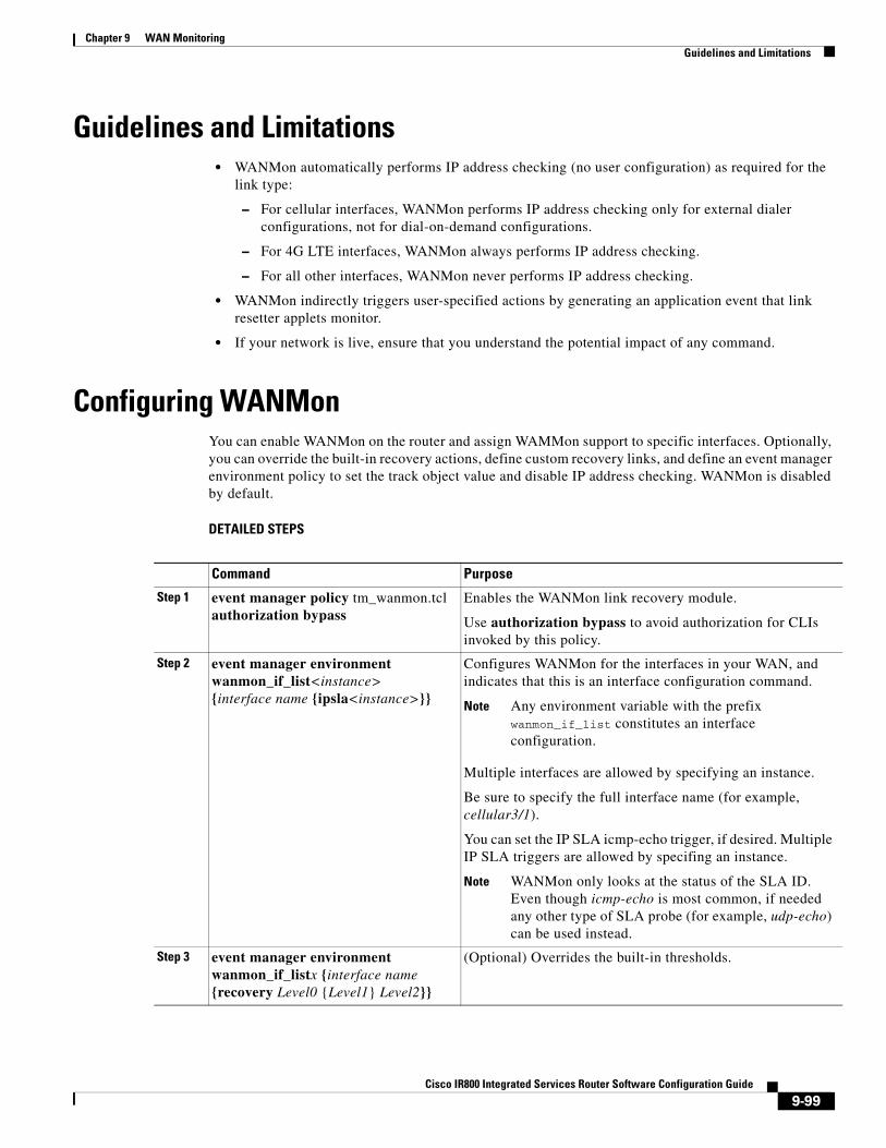
Chapter 9 WAN Monitoring Guidelines and Limitations
Guidelines and Limitations• WANMon automatically performs IP address checking (no user configuration) as required for the
link type:
– For cellular interfaces, WANMon performs IP address checking only for external dialer configurations, not for dial-on-demand configurations.
– For 4G LTE interfaces, WANMon always performs IP address checking.
– For all other interfaces, WANMon never performs IP address checking.
• WANMon indirectly triggers user-specified actions by generating an application event that link resetter applets monitor.
• If your network is live, ensure that you understand the potential impact of any command.
Configuring WANMonYou can enable WANMon on the router and assign WAMMon support to specific interfaces. Optionally, you can override the built-in recovery actions, define custom recovery links, and define an event manager environment policy to set the track object value and disable IP address checking. WANMon is disabled by default.
DETAILED STEPS
Command Purpose
Step 1 event manager policy tm_wanmon.tcl authorization bypass
Enables the WANMon link recovery module.
Use authorization bypass to avoid authorization for CLIs invoked by this policy.
Step 2 event manager environment wanmon_if_list<instance> {interface name {ipsla<instance>}}
Configures WANMon for the interfaces in your WAN, and indicates that this is an interface configuration command.
Note Any environment variable with the prefix wanmon_if_list constitutes an interface configuration.
Multiple interfaces are allowed by specifying an instance.
Be sure to specify the full interface name (for example, cellular3/1).
You can set the IP SLA icmp-echo trigger, if desired. Multiple IP SLA triggers are allowed by specifing an instance.
Note WANMon only looks at the status of the SLA ID. Even though icmp-echo is most common, if needed any other type of SLA probe (for example, udp-echo) can be used instead.
Step 3 event manager environment wanmon_if_listx {interface name {recovery Level0 {Level1} Level2}}
(Optional) Overrides the built-in thresholds.
9-99Cisco IR800 Integrated Services Router Software Configuration Guide

Chapter 9 WAN Monitoring Configuring WANMon
EXAMPLESevent manager policy tm_wanmon.tcl authorization bypass
The following examples are Event Manager commands to configure cellular and Ethernet interfaces:
event manager environment wanmon_if_list1 {cellular3/1 {ipsla 1}}
event manager environment wanmon_if_list2 {eth2/2 {ipsla 2}}
This example sets custom recovery thresholds:
event manager environment wanmon_if_list {cellular3/1 {recovery 20 {90 75} 600}}
where:
• The Level 0 threshold is set to 20 minutes after the link failure trigger. Level 0 recovery actions are performed for the cellular interface. Repeats indefinitely, no more than every 10 minutes (default).
• Level 1 threshold is set to 90 minutes. Level 1 recovery actions are performed for the cellular interface. Repeats no more frequently than every 75 minutes.
• The Level 2 threshold is set to 600 minutes (10 hours).
The following sets the track-stub-object value to 21:
conf ttrack 21 stub-objectevent manager environment wanmon_if_list {cellular3/1 {ipsla 1} {stub 21}}
Step 4 publish-event sub-system 798 type 2000 arg1 <interface name> arg2 <level>
(Optional) Configures custom recovery actions using link resetter applets.
<interface> is the full interface name (for example, cellular3/1).
<level> is 0, 1, or 2 to match the desired link recovery action.
Step 5 {stub <track-stub-id>} (Optional) Allows an event manager environment policy to set the track object value. WANMon can set a track-stub-object value to reflect the link state so that an external applet can track the stub object.
Step 6 event manager environment wanmon_if_listx {<interface name> {checkip <instance>}}
(Optional) Disables IP address checking.
Command Purpose
9-100Cisco IR800 Integrated Services Router Software Configuration Guide
Chapter 9 WAN Monitoring Verifying WANMon Configuration
Verifying WANMon ConfigurationUse the following steps to verify your WANMon configuraion.
DETAILED STEPS
EXAMPLEshow event manager policy registered1 script system multiple Off Thu Jan 16 18:44:29 2014 tm_wanmon.tclshow event manager environment1 wanmon_if_list {cell3/1 {ipsla 1}}
Configuration ExamplesThe following examples are provided:
• WANMon Cellular Interface Configuration Example, page 9-101
• Multiple WAN Link Monitoring Example, page 9-101
WANMon Cellular Interface Configuration Exampletrack 1 ip sla 1ip sla 1 icmp-echo 172.27.166.250 timeout 6000 frequency 300ip sla schedule 1 life forever start-time now
event manager environment wanmon_if_list {cellular3/1 {ipsla 1}}event manager policy tm_wanmon.tcl authorization bypass
Multiple WAN Link Monitoring Exampletrack 1 ip sla 1track 21 stub-objectip sla 1 icmp-echo 172.27.166.250 timeout 6000 frequency 300ip sla schedule 1 life forever start-time now
track 2 ip sla 2track 22 stub-objectip sla 2 icmp-echo 10.27.16.25 timeout 6000 frequency 300ip sla schedule 2 life forever start-time now
Command Purpose
Step 1 show event manager policy registered Displays the WAN monitoring policy.
Step 2 show event manager environment Displays the interface environment variables set during interface configuration.
9-101Cisco IR800 Integrated Services Router Software Configuration Guide

Chapter 9 WAN Monitoring Related Documentation
event manager environment wanmon_if_list1 {cellular3/1 {ipsla 1} {stub 21}}event manager policy tm_wanmon.tcl authorization bypass
Related DocumentationConfiguring WAN Backhaul Redundancy
9-102Cisco IR800 Integrated Services Router Software Configuration Guide
Cisco IR800 Integr
C H A P T E R 10
Ignition Power ManagementThis chapter provides a description and instructions for configuration of the Ignition Power Management feature of the IR829 router. It also keeps the IR829 up and running while the vehicle is stopped. Therefore, users won't have to wait for routers reload each time the vehicle was stopped. Ignition Power Management prevents the router from draining the charge of the battery on automotive applications.
When the engine is running it generates energy and recharges the battery. When the ignition is turned off, the IR829 can remain operational for a pre-determined period of time. This time period is programmable between 60 to 7200 seconds (2Hours) using the IOS ignition off-timer command.
Features of Ignition Power ManagementThe system software (IOS) tries to prevent the discharge of the battery with the following:
• Turning the router off if the vehicle has the ignition off for a period of time (programmable).
• Turning the router off if the battery voltage drops to a certain level (programmable).
• Attempts to protect the router by turning the router off if the battery voltage rises above a certain level (fixed amount of time).
The system software (IOS) logs the following events to the system log:
• When the user turns on or off the ignition management feature with CLI
• When the ignition is turned on or off
• When the ignition-off timer expires and the system goes off
• When the user enables or disables the feature through the CLI
• Tentatively logs the under-voltage and over-voltage events
10-103ated Services Router Software Configuration Guide

Chapter 10 Ignition Power Management Command Line Interface (CLI)
Command Line Interface (CLI)The Ignition Power Management feature of the IR800 series uses a command line interface.
Configuration CLIThe following commands are used to configure the feature.
Enable or Disable ignition power management:
ignition enable[no] ignition enable
Ignition off timer value. After the ignition is turned off the router will stay operational for this amount of time, then it shuts down if the ignition is still off:
ignition off-timer <value>
Over-voltage threshold. If the input voltage drops to levels below this threshold, it will cause the router to shut down
ignition undervoltage threshold <value>
Status CLIThe following command is used to show the status of the feature.
show ignition
The following is the expected output:
IR800#show ignition Status: Ignition management: Enabled Input voltage: 11.8 V Ignition status: Power on Shut down timer: 0.0 s to offThresholds: Undervoltage: 9.0 V Overvoltage: 32.0 V Undervoltage timer: 60.0 s Overvoltage timer: 0.5 s Ignition-Off timer: 900.0 s
Note While the default value for the IR829 is set to 9 volts, 12.2 volts is a much better value to set in order to provide better battery life to the vehicle
Troubleshooting CLIA set of CLIs are available for debugging purposes.
Note To turn the debug off, prepend a no prefix to the CLI command.
The commands are:
Enable debugging error conditions in the ignition management:
10-104Cisco IR800 Integrated Services Router Software Configuration Guide
Chapter 10 Ignition Power Management Command Line Interface (CLI)
debug ignition errors
Enable debugging operating events in the ignition management
debug ignition events
Enable debugging state transitions in the ignition management software:
debug ignition states IR800#debug ignition states IR800#*Mar 11 18:59:20.001: %IGNITION-5-IGN_DEBUG_SET: Ignition Management debugging states is turned on
*Mar 11 18:59:37.217: %IGNITION: Ignition mgmt FSM: IGNITION_MGMT_STATE_IGN_OFF*Mar 11 18:59:39.679: %IGNITION-5-IGN_TURNED_ON_OFF: The ignition is turned OFF*Mar 11 18:59:47.065: %IGNITION: Ignition mgmt FSM: IGNITION_MGMT_STATE_PWR_ON*Mar 11 18:59:49.527: %IGNITION-5-IGN_TURNED_ON_OFF: The ignition is turned ON
Enable all debugging conditions at once:
debug ignition all
IR800#debug ignition allIR800#conf t*Mar 11 19:01:06.737: %IGNITION-5-IGN_DEBUG_SET: Ignition Management debugging all is turned onEnter configuration commands, one per line. End with CNTL/Z.IR800(config)#igniIR800(config)#ignition timIR800(config)#ignition of IR800(config)#ignition off-timer 800IR800(config)#*Mar 11 19:01:20.357: %IGNITION: handling off-time CLI*Mar 11 19:01:23.115: %IGNITION: event set off timerdo show ignitionStatus: Ignition management: Enabled Input voltage: 12.2 V Ignition status: Power on Shutdown timer: 0.0 s to offThresholds: Undervoltage: 9.0 V Overvoltage: 32.0 V Undervoltage timer: 60.0 s Overvoltage timer: 0.5 s Ignition-Off timer: 800.0 s
Turn off debugging:
IR800(config)#no iginiIR800(config)#no igni IR800(config)#no ignition ofIR800(config)#no ignition off-timer ? <cr>
Note All debugging commands are cleared through a reboot of the device.
10-105Cisco IR800 Integrated Services Router Software Configuration Guide

Chapter 10 Ignition Power Management Command Examples
Command ExamplesThe following examples illustrate the CLI commands and the associated output expected.
Default ValuesThe following default settings apply to Ignition Power Management:
Command Examples Expected Output
Out of box configuration with no ignition management configured.
IR800#show ignition Status: Ignition management: Disabled Input voltage: 11.8 V Ignition status: Power on Shutdown timer: 0.0 s to offThresholds: Undervoltage: 9.0 V Overvoltage: 32.0 V Undervoltage timer: 60.0 s Overvoltage timer: 0.5 s Ignition-Off timer: 900.0 s
Configure the device for ignition off timer of 60, and ignition under-voltage threshold of 12.2.
1. Turn vehicle ignition switch off.
2. ignition off-timer 60
3. ignition undervoltage threshold 12.2
4. ignition enable
IR800#show ignition Status: Ignition management: Enabled Input voltage: 11.8 V Ignition status: Timing ignition off shut down Shut down timer: 53.0 s to offThresholds: Undervoltage: 12.2.0 V Overvoltage: 32.0 V Undervoltage timer: 60.0 s Overvoltage timer: 0.5 s Ignition-Off timer: 60.0 s
More?
Setting Value User Modifiable?
Ignition Power Management Feature Disabled Yes
Ignition off timer 15 minutes Yes
Under-Voltage threshold
Note While the default value is set to 9 volts, 12.2 volts is a much better value in order to provide better battery life to the vehicle.
9 Volts Yes
Under-Voltage timer 60 seconds No
10-106Cisco IR800 Integrated Services Router Software Configuration Guide

Chapter 10 Ignition Power Management Default Values
Over-Voltage threshold 32 Volts No
Over-Voltage timer 500 milliseconds No
Setting Value User Modifiable?
10-107Cisco IR800 Integrated Services Router Software Configuration Guide
Cisco IR800 Integr
C H A P T E R 11
Licensing and SecurityThis chapter provides details on the security licensing for the IR800 series.
The IOS feature set is aligned with the IOT 15.x M/T release strategy. They are:
• S800IUK9-15503M – Cisco IR800 Series UNIVERSAL
• S800INPEK9-15503M – Cisco IR800 Series UNIVERSAL – NO PAYLOAD ENCRYPTION
The Software License PIDs are shown in Table 11-1
Table 11-1 Software License PIDs
LicensingLicenses are installed at manufacturing. If the securityk9 technology-package is not installed, the crypto related functions will not work. See additional information under Hardware Crypto Support, page 11-109
To enable the RightToUse license, perform the following:
1. Accept the EULA
2. Enable the technology-package
3. Reload the IR800
Software PID Name Description
SL-IR800-IPB-K9
Cisco 800 Series Industrial Routers IP Base License
Routing (BGP, OSPF, RIP, EIGRP, ISIS,), PBR, IGMP/MLD, Multicast, QoS, AAA, Raw Sockets, Manageability
SL-IR800-SEC-K9
Cisco 800 Series Industrial Routers Security License
SSL, VPN, IPSec, DMVPN, FlexVPN, IOS Firewall
SL-IR800-SNPE-K9
Cisco 800 Series Industrial Routers No Payload Encryption License
SL-IR800-DATA-K9
Cisco 800 Series Industrial Routers Data License
L2TPv3, IP SLA, BFD, MPLS (subset)
SWAP1530-81-A1-K9
Cisco 1530 Series Unified & Autonomous 8.1 SW
IR829 AP803 WI-FI
11-108ated Services Router Software Configuration Guide

Chapter 11 Licensing and Security
Licensing CLI
IR800# show versionLicense Info:License UDI:-------------------------------------------------Device# PID SN-------------------------------------------------*1 IR829GW-LTE-GA-EK9 FGL194520VZ
Suite License Information for Module:'ir800’ --------------------------------------------------------------------------------Suite Suite Current Type Suite Next reboot --------------------------------------------------------------------------------
Technology Package License Information for Module:'ir800’ ------------------------------------------------------------------------Technology Technology-package Technology-package Current Type Next reboot ------------------------------------------------------------------------ipbase ipbasek9 Permanent ipbasek9security securityk9 Permanent securityk9data datak9 Permanent datak9
IR800# conf termlicense udi pid IR829GW-LTE-GA-EK9 sn FGL190726G8license accept end user agreementlicense boot module ir800 technology-package securityk9license boot module ir800 technology-package datak9
IR829#show license feature Feature name Enforcement Evaluation Subscription Enabled RightToUse ipbasek9 no no no yes no securityk9 yes yes no yes yes datak9 yes yes no yes yes
Hardware Crypto SupportThe initial IOS software release, 15.5(3)M, provided only software based crypto support. With the introduction of IOS software release 15.5(3)M, hardware based crypto support was added. A security license must be installed to enable hardware based crypto support.
To see which version of crypto support is being used:
IR800#show crypto engine configuration
crypto engine name: Virtual Private Network (VPN) Module crypto engine type: hardware State: Enabled Location: onboard 0 Product Name: Onboard-VPN HW Version: 1.0 Compression: No DES: Yes 3 DES: Yes AES CBC: Yes (128,192,256) AES CNTR: No Maximum buffer length: 4096 Maximum DH index: 0000 Maximum SA index: 0000
11-109Cisco IR800 Integrated Services Router Software Configuration Guide

Chapter 11 Licensing and Security
Maximum Flow index: 0256 Maximum RSA key size: 0000
crypto lib version: 22.0.0
crypto engine in slot: 0 platform: VPN hardware accelerator crypto lib version: 22.0.0
11-110Cisco IR800 Integrated Services Router Software Configuration Guide
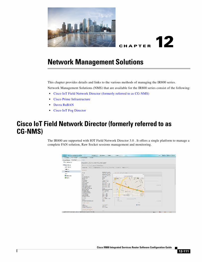
Cisco IR800 Integr
C H A P T E R 12
Network Management SolutionsThis chapter provides details and links to the various methods of managing the IR800 series.
Network Management Solutions (NMS) that are available for the IR800 series consist of the following:
• Cisco IoT Field Network Director (formerly referred to as CG-NMS)
• Cisco Prime Infrastructure
• Davra RuBAN
• Cisco IoT Fog Director
Cisco IoT Field Network Director (formerly referred to as CG-NMS)
The IR800 are supported with IOT Field Network Director 3.0 . It offers a single platform to manage a complete FAN solution, Raw Socket sessions management and monitoring.
12-111ated Services Router Software Configuration Guide
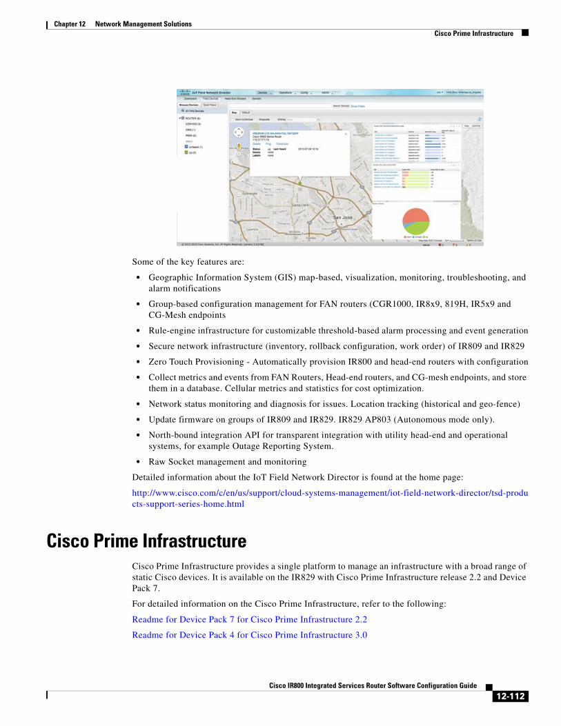
Chapter 12 Network Management Solutions Cisco Prime Infrastructure
Some of the key features are:
• Geographic Information System (GIS) map-based, visualization, monitoring, troubleshooting, and alarm notifications
• Group-based configuration management for FAN routers (CGR1000, IR8x9, 819H, IR5x9 and CG-Mesh endpoints
• Rule-engine infrastructure for customizable threshold-based alarm processing and event generation
• Secure network infrastructure (inventory, rollback configuration, work order) of IR809 and IR829
• Zero Touch Provisioning - Automatically provision IR800 and head-end routers with configuration
• Collect metrics and events from FAN Routers, Head-end routers, and CG-mesh endpoints, and store them in a database. Cellular metrics and statistics for cost optimization.
• Network status monitoring and diagnosis for issues. Location tracking (historical and geo-fence)
• Update firmware on groups of IR809 and IR829. IR829 AP803 (Autonomous mode only).
• North-bound integration API for transparent integration with utility head-end and operational systems, for example Outage Reporting System.
• Raw Socket management and monitoring
Detailed information about the IoT Field Network Director is found at the home page:
http://www.cisco.com/c/en/us/support/cloud-systems-management/iot-field-network-director/tsd-products-support-series-home.html
Cisco Prime InfrastructureCisco Prime Infrastructure provides a single platform to manage an infrastructure with a broad range of static Cisco devices. It is available on the IR829 with Cisco Prime Infrastructure release 2.2 and Device Pack 7.
For detailed information on the Cisco Prime Infrastructure, refer to the following:
Readme for Device Pack 7 for Cisco Prime Infrastructure 2.2
Readme for Device Pack 4 for Cisco Prime Infrastructure 3.0
12-112Cisco IR800 Integrated Services Router Software Configuration Guide

Chapter 12 Network Management Solutions Davra RuBAN
Note Only Inventory and Configuration Archive are Supported for the IR829.
Davra RuBANSingle platform for telematics and network management. See the following for more information:
Cisco Connected Fleet
Digital Solutions for Cisco Connected Mass Transit
Cisco Connected Roadways Drives Safety, Efficiency, Mobility, and Sustainability
Quickstart guide to setting up the RuBAN Bus
Cisco IoT Fog DirectorThe Cisco IoT Fog Director brings together the IOx Application Management Module, the ability to Understand your IOx resources, and IOx Application Rollout.
About Cisco IOxCisco IOx is an application enablement platform that provides uniform and consistent hosting capabilities for various types of applications, or applications, across various Cisco platforms. This platform brings together Cisco IOS, the industry-leading networking operating system, and Linux, the leading open source platform. Linux-based applications can run on Cisco devices in the Cisco IOx framework, so using this platform, you can bring custom applications and interfaces to the network.
With Cisco IOx, developers can create a wide variety of IoT applications, such as data aggregation system and control systems.
About Cisco Fog DirectorCisco Fog Director allows administrators to manage, administer, monitor, and troubleshoot Cisco IOx applications and devices. It provides a web-based user interface from which you can perform activities that include the following:
• Install and uninstall applications
• Start and stop applications
• Upgrade applications
• View the status of applications
• Backup and restore applications data
• Monitor applications and devices and collect statistics
• Create and obtain debug logs for troubleshooting
Detailed information about the Cisco Fog Director is found at the home page:
http://www.cisco.com/c/en/us/support/cloud-systems-management/fog-director/tsd-products-support-series-home.html
12-113Cisco IR800 Integrated Services Router Software Configuration Guide

Chapter 12 Network Management Solutions Cisco IoT Fog Director
OID and InventoryTo find out information about your model, use the show inventory oid command:
IR829IR829#show inventory oidNAME: "IR829GW-LTE-GA-EK9", DESCR: "IR829GW-LTE-GA-EK9 chassis, Hw Serial#: FGL194520VZ, Hw Revision: 2.0"PID: IR829GW-LTE-GA-EK9, VID: V01 , SN: FGL194520VZOID: 1.3.6.1.4.1.9.12.3.1.3.1582
NAME: "Modem 0 on Cellular0", DESCR: "Sierra Wireless MC7304 4G-GA"PID: MC7304 , VID: 1.0, SN: 352761060426997OID: 1.3.6.1.4.1.9.12.3.1.9.15.88
IR809
IR809#show inventory oidNAME: "IR809G-LTE-GA-K9", DESCR: "IR809G-LTE-GA-K9 chassis, Hw Serial#: JMX1915X00Q, Hw Revision: 1.0"PID: IR809G-LTE-GA-K9 , VID: V00, SN: JMX1915X00QOID: 1.3.6.1.4.1.9.12.3.1.3.1581
NAME: "Modem 0 on Cellular0", DESCR: "Sierra Wireless MC7304 4G-GA"PID: MC7304 , VID: 1.0, SN: 352761060206340OID: 1.3.6.1.4.1.9.12.3.1.9.15.88
12-114Cisco IR800 Integrated Services Router Software Configuration Guide