cisco ios xr multicast configuration guide for the … · cisco ios xr multicast configuration...
TRANSCRIPT

Cisco IOS XR Multicast Configuration Guide for the Cisco CRS Router,Release 5.2.xFirst Published: 2014-07-01
Last Modified: 2014-10-01
Americas HeadquartersCisco Systems, Inc.170 West Tasman DriveSan Jose, CA 95134-1706USAhttp://www.cisco.comTel: 408 526-4000 800 553-NETS (6387)Fax: 408 527-0883

THE SPECIFICATIONS AND INFORMATION REGARDING THE PRODUCTS IN THIS MANUAL ARE SUBJECT TO CHANGE WITHOUT NOTICE. ALL STATEMENTS,INFORMATION, AND RECOMMENDATIONS IN THIS MANUAL ARE BELIEVED TO BE ACCURATE BUT ARE PRESENTED WITHOUT WARRANTY OF ANY KIND,EXPRESS OR IMPLIED. USERS MUST TAKE FULL RESPONSIBILITY FOR THEIR APPLICATION OF ANY PRODUCTS.
THE SOFTWARE LICENSE AND LIMITEDWARRANTY FOR THE ACCOMPANYING PRODUCT ARE SET FORTH IN THE INFORMATION PACKET THAT SHIPPED WITHTHE PRODUCT AND ARE INCORPORATED HEREIN BY THIS REFERENCE. IF YOU ARE UNABLE TO LOCATE THE SOFTWARE LICENSE OR LIMITED WARRANTY,CONTACT YOUR CISCO REPRESENTATIVE FOR A COPY.
The Cisco implementation of TCP header compression is an adaptation of a program developed by the University of California, Berkeley (UCB) as part of UCB's public domain versionof the UNIX operating system. All rights reserved. Copyright © 1981, Regents of the University of California.
NOTWITHSTANDINGANYOTHERWARRANTYHEREIN, ALL DOCUMENT FILES AND SOFTWARE OF THESE SUPPLIERS ARE PROVIDED “AS IS"WITH ALL FAULTS.CISCO AND THE ABOVE-NAMED SUPPLIERS DISCLAIM ALL WARRANTIES, EXPRESSED OR IMPLIED, INCLUDING, WITHOUT LIMITATION, THOSE OFMERCHANTABILITY, FITNESS FORA PARTICULAR PURPOSEANDNONINFRINGEMENTORARISING FROMACOURSEOFDEALING, USAGE, OR TRADE PRACTICE.
IN NO EVENT SHALL CISCO OR ITS SUPPLIERS BE LIABLE FOR ANY INDIRECT, SPECIAL, CONSEQUENTIAL, OR INCIDENTAL DAMAGES, INCLUDING, WITHOUTLIMITATION, LOST PROFITS OR LOSS OR DAMAGE TO DATA ARISING OUT OF THE USE OR INABILITY TO USE THIS MANUAL, EVEN IF CISCO OR ITS SUPPLIERSHAVE BEEN ADVISED OF THE POSSIBILITY OF SUCH DAMAGES.
Any Internet Protocol (IP) addresses and phone numbers used in this document are not intended to be actual addresses and phone numbers. Any examples, command display output, networktopology diagrams, and other figures included in the document are shown for illustrative purposes only. Any use of actual IP addresses or phone numbers in illustrative content is unintentionaland coincidental.
Cisco and the Cisco logo are trademarks or registered trademarks of Cisco and/or its affiliates in the U.S. and other countries. To view a list of Cisco trademarks, go to this URL: http://www.cisco.com/go/trademarks. Third-party trademarks mentioned are the property of their respective owners. The use of the word partner does not imply a partnershiprelationship between Cisco and any other company. (1110R)
© 2016 Cisco Systems, Inc. All rights reserved.

C O N T E N T S
P r e f a c e Preface ix
Changes to This Document ix
Obtaining Documentation and Submitting a Service Request ix
C H A P T E R 1 New and Changed Multicast Features 1
New and Changed Multicast Features 1
C H A P T E R 2 Implementing Multicast Routing on Cisco IOS XR Software 3
Prerequisites for Implementing Multicast Routing 4
Information About Implementing Multicast Routing 5
Key Protocols and Features Supported in the Cisco IOS XR Software Multicast Routing
Implementation 5
Multicast Routing Functional Overview 6
Multicast Routing Implementation 6
PIM-SM, PIM-SSM, and PIM-BIDIR 7
PIM-SM Operations 7
PIM-SSM Operations 8
PIM-Bidirectional Operations 8
Restrictions for PIM-SM and PIM-SSM, and PIM BIDIR 8
Internet Group Management Protocol and Multicast Listener Discovery 9
IGMP and MLD Versions 9
IGMP Routing Example 10
Protocol Independent Multicast 11
PIM-Sparse Mode 11
PIM-Source Specific Multicast 12
PIM-Bidirectional Mode 12
PIM Shared Tree and Source Tree (Shortest Path Tree) 13
Cisco IOS XR Multicast Configuration Guide for the Cisco CRS Router, Release 5.2.x iii

Multicast-Intact 14
Designated Routers 15
Rendezvous Points 16
Auto-RP 17
PIM Bootstrap Router 18
Reverse-Path Forwarding 18
Multicast Non-Stop Routing 18
Failure Scenarios in NSR 19
Multicast VPN 19
Multicast VPN Routing and Forwarding 20
Multicast Distribution Tree Tunnels 20
InterAS Support on Multicast VPN 21
BGP Requirements 22
Multitopology Routing 22
Multicast VPN Extranet Routing 23
Information About Extranets 23
Information About the Extranet MVPN Routing Topology 24
RPF Policies in an Extranet 26
MVPN Bidirectional Overview 26
Multicast VPN Hub and Spoke Topology 27
Realizing the Hub and Spoke Topology 27
Label Switched Multicast (LSM) Multicast Label Distribution Protocol (mLDP) based
Multicast VPN (mVPN) Support 28
Benefits of LSM MLDP based MVPN 28
Configuring MLDP MVPN 29
P2MP and MP2MP Label Switched Paths 29
Packet Flow in mLDP-based Multicast VPN 30
Realizing a mLDP-based Multicast VPN 30
Characteristics of mLDP Profiles 30
Configuration rules for profiles 37
MLDP inband signaling 37
Summary of Supported MVPN Profiles 38
Configuration Process for MLDP MVPN (Intranet) 39
Multipoint Label Distribution Protocol Route Policy Map 41
Configuring mLDP User Interface (Opaque Types) Using the Routing Policy 42
Cisco IOS XR Multicast Configuration Guide for the Cisco CRS Router, Release 5.2.xiv
Contents

Configuring the mLDP User Interface for LDP Opaque Global ID Using the Routing
Policy 43
Configuring the mLDP User Interface for LDP Opaque IPv4 Using the Routing
Policy 44
Configuring the mLDP User Interface for LDP Opaque IPv6 Using the Routing
Policy 45
Configuring the mLDP User Interface for LDP Opaque MDT Using the Routing
Policy 46
Configuring the mLDP User Interface for LDP Opaque Static ID Using the Routing
Policy 47
Configuring the mLDP User Interface for LDP Opaque Recursive Using the Routing
Policy 48
Configuring the mLDP User Interface for LDP Opaque Recursive-RD Using the
Routing Policy 49
Configuring the mLDP User Interface for LDP Opaque VPNv4 Using the Routing
Policy 50
Configuring the mLDP User Interface for LDP Opaque VPNv6 Using the Routing
Policy 51
Configuring mLDP FEC at the Root Node 52
Configuring the mLDP FEC at the Root Node Using the Route Policy 52
Configuring the mLDP User Interface to Filter Label Mappings 53
Configuring the mLDP User Interface to Filter Label Mappings 54
Configuring the mLDP User Interface for Feature Filtering 55
Configuring the mLDP User Interface for Feature Filtering - MoFRR 55
Configuring the mLDP User Interface for Feature Filtering - Make-before-break 56
Configuring the mLDP User Interface for Feature Filtering - Recursive FEC 58
Limitations of Route Policy Map 59
Next-Generation Multicast VPN 60
Supported Features 60
PE-PE Ingress Replication 63
Multicast IRB 63
Supported bridge port types 64
Restrictions 64
Multicast IRB 64
Multicast Source Discovery Protocol 64
Cisco IOS XR Multicast Configuration Guide for the Cisco CRS Router, Release 5.2.x v
Contents

VRF-aware MSDP 65
Multicast Nonstop Forwarding 65
Multicast Configuration Submodes 65
Multicast-Routing Configuration Submode 66
PIM Configuration Submode 66
IGMP Configuration Submode 66
MLD Configuration Submode 66
MSDP Configuration Submode 66
Understanding Interface Configuration Inheritance 66
Understanding Interface Configuration Inheritance Disablement 67
Understanding Enabling and Disabling Interfaces 68
Multicast Routing Information Base 68
Multicast Forwarding Information Base 68
MSDP MD5 Password Authentication 69
How to Implement Multicast Routing 69
Configuring PIM-SM and PIM-SSM 69
Configuring Native PIM BIDIR 71
Configuring MVPN GRE BIDIR 74
Configuring MVPN MLDP BIDIR 83
Configuring a Static RP and Allowing Backward Compatibility 90
Configuring Auto-RP to Automate Group-to-RP Mappings 92
Configuring the Bootstrap Router 94
Calculating Rates per Route 96
Configuring Multicast Nonstop Forwarding 98
Configuring Multicast VPN 100
Prerequisites for Multicast VPN 101
Restrictions for Multicast VPN for Multicast Routing 101
Enabling a VPN for Multicast Routing 101
Specifying the PIM VRF Instance 104
Specifying the IGMP VRF Instance 105
Configuring the MDT Source per VRF 105
Configuring Label Switched Multicast 108
Verification of LSM mLDP based MVPN Configuration 113
Configuring Multitopology Routing 116
Restrictions for Configuring Multitopology Routing 116
Cisco IOS XR Multicast Configuration Guide for the Cisco CRS Router, Release 5.2.xvi
Contents

Information About Multitopology Routing 117
Configuring an RPF Topology in PIM 117
Configuring MVPN Extranet Routing 119
Prerequisites for MVPN Extranet Routing 119
Restrictions for MVPN Extranet Routing 119
Configuring VPN Route Targets 120
Interconnecting PIM-SM Domains with MSDP 121
Controlling Source Information on MSDP Peer Routers 124
Configuring MSDP MD5 Password Authentication 126
Configuring VRF for MSDP 127
Multicast only fast reroute (MoFRR) 128
Operating Modes of MoFRR 128
Configuring MoFRR 129
RIB-based MoFRR 129
Configuring Route Policy for Static RPF 130
Point-to-Multipoint Traffic Engineering Label-Switched Multicast 131
Point to Multipoint LSP(P2MP) 131
Multicast Routing Protocol support for P2MP 132
Enabling Multicast Forwarding Over Tunnel Interface (at Ingress Node) 132
P2MP configurations at egress node and bud node 133
Configuring Static Reverse Path Forwarding (RPF) 133
Configuring Core Tree Protocol 134
Configuration Examples for Implementing Multicast Routing on Software 135
MSDP Anycast RP Configuration on Cisco IOS XR Software: Example 135
Bidir-PIM Configuration on Software: Example 136
Calculating Rates per Route: Example 137
Preventing Auto-RP Messages from Being Forwarded on Software: Example 138
Inheritance in MSDP on Software: Example 138
MSDP-VRF: Example 139
Configuring Route Policy for Static RPF: Example 139
Configuring IPv4 Multicast VPN: Example 139
Configuring MVPN to Advertise Routes Between the CE and the PE Using OSPF:
Example 140
Configuring MVPN to Advertise Routes Between the CE and the PE Using BGP:
Example 144
Cisco IOS XR Multicast Configuration Guide for the Cisco CRS Router, Release 5.2.x vii
Contents

Configuration Examples for MVPN Profiles 148
Configuration Examples for Inband mLDP profiles 148
Configuration Examples for P2MP-TE profiles 149
Configuration examples for Partitioned mLDP profiles 152
Configuration Examples for Rosen-mGRE profiles 154
Configuration Examples for Rosen mLDP profiles 156
Configuring Multitopology Routing: Example 159
Configuring MVPN Extranet Routing: Example 160
Configuring the Source MVRF on the Receiver PE Router: Example 160
Configuring the Receiver MVRF on the Source PE Router: Example 162
Configuring Multicast Hub and Spoke Topology: Example 165
Hub and Spoke Non-Turnaround Configuration: Example 165
Hub and Spoke with Turnaround: Example 174
Configuring LSM based MLDP: Examples 180
Additional References 190
C H A P T E R 3 Implementing Automatic Multicast Routing: 193
Automatic Multicast Tunneling 193
Advantages of AMT 193
Prerequisites for configuring AMT 194
Restrictions for AMT 194
Implementing AMT 195
AMT Message Exchanges 195
AMT Tunnel and Traffic Types 196
Out of Resource mode 196
Enabling AMT 196
Configuring AMT 197
Configuration Examples for Implementing AMT 198
Enabling AMT: Example 199
AMT Maximum Gateway Configuration: Example 199
AMT MTU Configuration: Example 199
AMT TOS Configuration: Example 199
Cisco IOS XR Multicast Configuration Guide for the Cisco CRS Router, Release 5.2.xviii
Contents

Preface
The preface contains these sections:
• Changes to This Document, page ix
• Obtaining Documentation and Submitting a Service Request, page ix
Changes to This DocumentThis table lists the technical changes made to this document since it was first printed.
SummaryDate
Initial release of this documentJuly 2014
Updates to this document for Release 5.2.2.October 2014
Obtaining Documentation and Submitting a Service RequestFor information on obtaining documentation, using the Cisco Bug Search Tool (BST), submitting a servicerequest, and gathering additional information, see What's New in Cisco Product Documentation.
To receive new and revised Cisco technical content directly to your desktop, you can subscribe to the What'sNew in Cisco Product Documentation RSS feed. RSS feeds are a free service.
Cisco IOS XR Multicast Configuration Guide for the Cisco CRS Router, Release 5.2.x ix

Cisco IOS XR Multicast Configuration Guide for the Cisco CRS Router, Release 5.2.xx
PrefaceObtaining Documentation and Submitting a Service Request
C H A P T E R 1New and Changed Multicast Features
This chapter lists all the features that have been added or modified in this guide. The table also containsreferences to these feature documentation sections.
• New and Changed Multicast Features, page 1
New and Changed Multicast FeaturesThis table summarizes the new and changed information for Multicast Configuration Guide and provideinformation on where they are documented.
Table 1: New and Changed Multicast Feature Information
Where DocumentedChanged in ReleaseDescriptionFeature
Multipoint Label DistributionProtocol Route PolicyMap, onpage 41
Release 5.2.0This feature was introduced.MVPN-mLDP Filtering in theCore
Multicast Non-Stop Routing,on page 18
Release 5.2.2This feature was introduced.Multicast NSR
Supported Features, on page60
Release 5.2.2This feature was enhanced toinclude the supported featureson Next Generation MVPN.
Next Generation MVPN
Cisco IOS XR Multicast Configuration Guide for the Cisco CRS Router, Release 5.2.x 1

Cisco IOS XR Multicast Configuration Guide for the Cisco CRS Router, Release 5.2.x2
New and Changed Multicast FeaturesNew and Changed Multicast Features

C H A P T E R 2Implementing Multicast Routing on Cisco IOS XRSoftware
Multicast routing is a bandwidth-conserving technology that reduces traffic by simultaneously deliveringa single stream of information to potentially thousands of corporate recipients and homes. Applications thattake advantage of multicast routing include video conferencing, corporate communications, distance learning,and distribution of software, stock quotes, and news.
This document assumes that you are familiar with IPv4 and IPv6 multicast routing configuration tasks andconcepts for Cisco IOS XR Software .
Multicast routing allows a host to send packets to a subset of all hosts as a group transmission rather than toa single host, as in unicast transmission, or to all hosts, as in broadcast transmission. The subset of hosts isknown as groupmembers and are identified by a single multicast group address that falls under the IP ClassD address range from 224.0.0.0 through 239.255.255.255.
For detailed conceptual information about multicast routing and complete descriptions of the multicast routingcommands listed in this module, you can refer to the Related Documents, on page 190.
Feature History for Configuring Multicast Routing on the Cisco CRS Routers
ModificationRelease
This feature was introduced.Release 2.0
Support was added for the for IPv6 routing protocol and for thebootstrap router (BSR) feature.
Release 3.2
Multicast VPNv4 was supported.Release 3.5.0
The following new features or functionality were added:
• Support was added for multitopology routing within adefault VRF table.
• A new configuration procedure was added for calculatingrate per route.
Release 3.7.0
Cisco IOS XR Multicast Configuration Guide for the Cisco CRS Router, Release 5.2.x 3

ModificationRelease
Support was added for these features:
• Multicast-only fast reroutes (MoFRR).
• Point-to-multipointMPLS label-switchedmulticast routing.
Release 3.9.0
Support for Auto-RP Lite and MVPN Hub and Spoke Topologywere added.
Release 4.0.0
Support for Label Switched Multicast (LSM) Multicast LabelDistribution Protocol (mLDP) based Multicast VPN (mVPN)was added.
Release 4.1.1
Support was added for these features:
• IPv4 Multicast over v4GRE
• MVPN v4 over v4GRE
• InterAS Support on Multicast VPN.
Release 4.2.1
MVPN IPv6 over IPv4 GRE feature was introduced.Release 6.1.2
• Prerequisites for Implementing Multicast Routing, page 4
• Information About Implementing Multicast Routing, page 5
• How to Implement Multicast Routing, page 69
• Multicast only fast reroute (MoFRR), page 128
• Configuring Route Policy for Static RPF, page 130
• Point-to-Multipoint Traffic Engineering Label-Switched Multicast, page 131
• Configuration Examples for Implementing Multicast Routing on Software, page 135
• Additional References, page 190
Prerequisites for Implementing Multicast Routing• You must install and activate the multicast pie.
• For detailed information about optional PIE installation, see Cisco IOS XR Getting Started Guide forthe Cisco CRS Router
• For MLDP, an MPLS PIE has to be installed.
• Youmust be in a user group associated with a task group that includes the proper task IDs. The commandreference guides include the task IDs required for each command. If you suspect user group assignmentis preventing you from using a command, contact your AAA administrator for assistance.
Cisco IOS XR Multicast Configuration Guide for the Cisco CRS Router, Release 5.2.x4
Implementing Multicast Routing on Cisco IOS XR SoftwarePrerequisites for Implementing Multicast Routing

• You must be familiar with IPv4 and IPv6 multicast routing configuration tasks and concepts.
• Unicast routing must be operational.
• To enable multicast VPN, you must configure a VPN routing and forwarding (VRF) instance.
Information About Implementing Multicast Routing
Key Protocols and Features Supported in the Cisco IOS XR Software MulticastRouting Implementation
Table 2: Supported Features for IPv4 and IPv6 on Cisco CRS Routers
IPv6 SupportIPv4 SupportFeature
Yes (MLD v1/2)Yes (IGMP v1/2/3)Dynamic host registration
Yes (MLD v2)Yes (IGMP v3)Explicit tracking of hosts, groups,and channels
YesYesPIM-SM1
YesYesPIM-SSM2
YesYesPIM-Bidir3
NoYesAuto-RP
Yes4YesMulticast VPN
YesYesBSR5
NoYesMSDP6
YesYesBGP7
YesYesMulticast NSF8
NoYesOOR handling9
1 Protocol Independent Multicast in sparse mode2 Protocol Independent Multicast in Source-Specific Multicast3 Protocol Independent Multicast Bidirectional4 IPv6 support on Cisco XR 12000 Series Router only5 PIM bootstrap router6 Multicast Source Discovery Protocol
Cisco IOS XR Multicast Configuration Guide for the Cisco CRS Router, Release 5.2.x 5
Implementing Multicast Routing on Cisco IOS XR SoftwareInformation About Implementing Multicast Routing

7 Multiprotocol Border Gateway Protocol8 Nonstop forwarding9 Out of resource
Multicast Routing Functional OverviewTraditional IP communication allows a host to send packets to a single host (unicast transmission) or to allhosts (broadcast transmission). Multicast provides a third scheme, allowing a host to send a single data streamto a subset of all hosts (group transmission) at about the same time. IP hosts are known as group members.
Packets delivered to group members are identified by a single multicast group address. Multicast packets aredelivered to a group using best-effort reliability, just like IP unicast packets.
The multicast environment consists of senders and receivers. Any host, regardless of whether it is a memberof a group, can send to a group. However, only the members of a group receive the message.
A multicast address is chosen for the receivers in a multicast group. Senders use that group address as thedestination address of a datagram to reach all members of the group.
Membership in a multicast group is dynamic; hosts can join and leave at any time. There is no restriction onthe location or number of members in a multicast group. A host can be a member of more than one multicastgroup at a time.
How active a multicast group is and what members it has can vary from group to group and from time to time.A multicast group can be active for a long time, or it may be very short-lived. Membership in a group canchange constantly. A group that has members may have no activity.
Routers use the Internet GroupManagement Protocol (IGMP) (IPv4) andMulticast Listener Discovery (MLD)(IPv6) to learn whether members of a group are present on their directly attached subnets. Hosts join multicastgroups by sending IGMP or MLD report messages.
Many multimedia applications involve multiple participants. Multicast is naturally suitable for thiscommunication paradigm.
Multicast Routing ImplementationCisco IOS XR Software supports the following protocols to implement multicast routing:
• IGMP and MLD are used (depending on the IP protocol) between hosts on a LAN and the routers onthat LAN to track the multicast groups of which hosts are members.
• Protocol Independent Multicast in sparse mode (PIM-SM) is used between routers so that they can trackwhich multicast packets to forward to each other and to their directly connected LANs.
• Protocol Independent Multicast in Source-Specific Multicast (PIM-SSM) is similar to PIM-SMwith theadditional ability to report interest in receiving packets from specific source addresses (or from all butthe specific source addresses), to an IP multicast address.
• PIM-SSM is made possible by IGMPv3 andMLDv2. Hosts can now indicate interest in specific sourcesusing IGMPv3 and MLDv2. SSM does not require a rendezvous point (RP) to operate.
• PIM Bidirectional is a variant of the Protocol Independent Multicast suit of routing protocols for IPmulticast. PIM-BIDIR is designed to be used for many-to-many applications within individual PIMdomains.
Cisco IOS XR Multicast Configuration Guide for the Cisco CRS Router, Release 5.2.x6
Implementing Multicast Routing on Cisco IOS XR SoftwareMulticast Routing Functional Overview
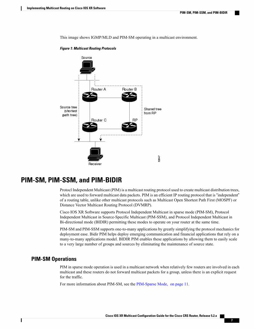
This image shows IGMP/MLD and PIM-SM operating in a multicast environment.
Figure 1: Multicast Routing Protocols
PIM-SM, PIM-SSM, and PIM-BIDIRProtocl Independent Multicast (PIM) is a multicast routing protocol used to create multicast distribution trees,which are used to forward multicast data packets. PIM is an efficient IP routing protocol that is “independent”of a routing table, unlike other multicast protocols such as Multicast Open Shortest Path First (MOSPF) orDistance Vector Multicast Routing Protocol (DVMRP).
Cisco IOS XR Software supports Protocol Independent Multicast in sparse mode (PIM-SM), ProtocolIndependent Multicast in Source-Specific Multicast (PIM-SSM), and Protocol Independent Multicast inBi-directional mode (BIDIR) permitting these modes to operate on your router at the same time.
PIM-SM and PIM-SSM supports one-to-many applications by greatly simplifying the protocol mechanics fordeployment ease. Bidir PIM helps deploy emerging communication and financial applications that rely on amany-to-many applications model. BIDIR PIM enables these applications by allowing them to easily scaleto a very large number of groups and sources by eliminating the maintenance of source state.
PIM-SM OperationsPIM in sparse mode operation is used in a multicast network when relatively few routers are involved in eachmulticast and these routers do not forward multicast packets for a group, unless there is an explicit requestfor the traffic.
For more information about PIM-SM, see the PIM-Sparse Mode, on page 11.
Cisco IOS XR Multicast Configuration Guide for the Cisco CRS Router, Release 5.2.x 7
Implementing Multicast Routing on Cisco IOS XR SoftwarePIM-SM, PIM-SSM, and PIM-BIDIR

PIM-SSM OperationsPIM in Source-Specific Multicast operation uses information found on source addresses for a multicast groupprovided by receivers and performs source filtering on traffic.
• By default, PIM-SSM operates in the 232.0.0.0/8 multicast group range for IPv4 and ff3x::/32 (wherex is any valid scope) in IPv6. To configure these values, use the ssm range command.
• If SSM is deployed in a network already configured for PIM-SM, only the last-hop routers must beupgraded with Cisco IOS XR Software that supports the SSM feature.
• No MSDP SA messages within the SSM range are accepted, generated, or forwarded.
PIM-Bidirectional OperationsPIM Bidirectional (BIDIR) has one shared tree from sources to RP and from RP to receivers. This is unlikethe PIM-SM, which is unidirectional by nature with multiple source trees - one per (S,G) or a shared tree fromreceiver to RP and multiple SG trees from RP to sources.
Benefits of PIM BIDIR are as follows:
• As many sources for the same group use one and only state (*, G), only minimal states are required ineach router.
• No data triggered events.
• Rendezvous Point (RP) router not required. The RP address only needs to be a routable address andneed not exist on a physical device.
Restrictions for PIM-SM and PIM-SSM, and PIM BIDIR
Interoperability with SSM
PIM-SM operations within the SSM range of addresses change to PIM-SSM. In this mode, only PIM (S,G)join and prune messages are generated by the router, and no (S,G) RP shared tree or (*,G) shared tree messagesare generated.
IGMP Version
To report multicast memberships to neighboring multicast routers, hosts use IGMP, and all routers on thesubnet must be configured with the same version of IGMP.
A router running Cisco IOS XR Software does not automatically detect Version 1 systems. You must use theversion command in router IGMP configuration submode to configure the IGMP version.
MLD Version
To report multicast memberships to neighboring multicast routers, routers use MLD, and all routers on thesubnet must be configured with the same version of MLD.
PIM-BIDIR Restrictions
• PIM SSM is not supported in the core for BIDIR traffic in the MVRF.
Cisco IOS XR Multicast Configuration Guide for the Cisco CRS Router, Release 5.2.x8
Implementing Multicast Routing on Cisco IOS XR SoftwarePIM-SM, PIM-SSM, and PIM-BIDIR

• Anycast RP is not supported for BIDIR in the MVRF and in native.
• Data MDT is not supported for BIDIR in the MVRF.
• Extranet is not supported for BIDIR traffic.
• MVPN BIDIR in the core is not supported.
• The SM scale is about 350 VRFs per system and the maximum BIDIR scale is expected to be around10% of SM scale. Thus, the BIDIR scale is about 35 VRFs.
E3 Linecard Limitations
• Only 1k BIDIR routes (without qos) are supported on E3.
• If multicast QoS is applied, then we recommend having only <= 1k routes.
• Only 10 egress interfaces are supported.
• If Multicast QoS is enabled on E3, then policy can have a maximum of 5 queuing classes, (includingclass default), assuming 1k scale.
It is recommended to have less BIDIR scale on E3 Linecard, as it requires lot of resources to supportBIDIR support such as MGID usage, TLU memory, and CPU utilization.
Note
Internet Group Management Protocol and Multicast Listener DiscoveryCisco IOS XR Software provides support for Internet Group Management Protocol (IGMP) over IPv4 andMulticast Listener Discovery (MLD) over IPv6.
IGMP (and MLD) provide a means for hosts to indicate which multicast traffic they are interested in and forrouters to control and limit the flow of multicast traffic throughout the network. Routers build state by meansof IGMP and MLD messages; that is, router queries and host reports.
A set of queries and hosts that receive multicast data streams from the same source is called amulticast group.Hosts use IGMP and MLD messages to join and leave multicast groups.
IGMPmessages use group addresses, which are Class D IP addresses. The high-order four bits of a Class Daddress are 1110. Host group addresses can be in the range 224.0.0.0 to 239.255.255.255. The address224.0.0.0 is guaranteed not to be assigned to any group. The address 224.0.0.1 is assigned to all systemson a subnet. The address 224.0.0.2 is assigned to all routers on a subnet.
Note
IGMP and MLD VersionsThe following points describe IGMP versions 1, 2, and 3:
• IGMP Version 1 provides for the basic query-response mechanism that allows the multicast router todetermine which multicast groups are active and for other processes that enable hosts to join and leavea multicast group.
Cisco IOS XR Multicast Configuration Guide for the Cisco CRS Router, Release 5.2.x 9
Implementing Multicast Routing on Cisco IOS XR SoftwareInternet Group Management Protocol and Multicast Listener Discovery

• IGMP Version 2 extends IGMP allowing such features as the IGMP query timeout and the maximumquery-response time. See RFC 2236.
MLDv1 provides the same functionality (under IPv6) as IGMP Version 2.Note
• IGMP Version 3 permits joins and leaves for certain source and group pairs instead of requesting trafficfrom all sources in the multicast group.
MLDv2 provides the same functionality (under IPv6) as IGMP Version 3.Note
IGMP Routing ExampleFigure 2: IGMPv3 Signaling, on page 10 illustrates two sources, 10.0.0.1 and 10.0.1.1, that are multicastingto group 239.1.1.1. The receiver wants to receive traffic addressed to group 239.1.1.1 from source 10.0.0.1but not from source 10.0.1.1. The host must send an IGMPv3 message containing a list of sources and groups(S, G) that it wants to join and a list of sources and groups (S, G) that it wants to leave. Router C can now usethis information to prune traffic from Source 10.0.1.1 so that only Source 10.0.0.1 traffic is being deliveredto
Router C.
Figure 2: IGMPv3 Signaling
Cisco IOS XR Multicast Configuration Guide for the Cisco CRS Router, Release 5.2.x10
Implementing Multicast Routing on Cisco IOS XR SoftwareInternet Group Management Protocol and Multicast Listener Discovery

When configuring IGMP, ensure that all systems on the subnet support the same IGMP version. The routerdoes not automatically detect Version 1 systems. Configure the router for Version 2 if your hosts do notsupport Version 3.
Note
Protocol Independent MulticastProtocol Independent Multicast (PIM) is a routing protocol designed to send and receive multicast routingupdates. Proper operation of multicast depends on knowing the unicast paths towards a source or an RP. PIMrelies on unicast routing protocols to derive this reverse-path forwarding (RPF) information. As the namePIM implies, it functions independently of the unicast protocols being used. PIM relies on the RoutingInformation Base (RIB) for RPF information.
If the multicast subsequent address family identifier (SAFI) is configured for Border Gateway Protocol (BGP),or if multicast intact is configured, a separate multicast unicast RIB is created and populated with the BGPmulticast SAFI routes, the intact information, and any IGP information in the unicast RIB. Otherwise, PIMgets information directly from the unicast SAFI RIB. Both multicast unicast and unicast databases are outsideof the scope of PIM.
The Cisco IOS XR implementation of PIM is based on RFC 4601 Protocol Independent Multicast - SparseMode (PIM-SM): Protocol Specification. For more information, see RFC 4601 and the Protocol IndependentMulticast (PIM): Motivation and Architecture Internet Engineering Task Force (IETF) Internet draft.
Cisco IOS XR Software supports PIM-SM, PIM-SSM, PIMBidir, and PIMVersion 2 only. PIMVersion 1hello messages that arrive from neighbors are rejected.
Note
PIM-Sparse ModeTypically, PIM in sparse mode (PIM-SM) operation is used in a multicast network when relatively few routersare involved in each multicast. Routers do not forward multicast packets for a group, unless there is an explicitrequest for traffic. Requests are accomplished using PIM join messages, which are sent hop by hop towardthe root node of the tree. The root node of a tree in PIM-SM is the rendezvous point (RP) in the case of ashared tree or the first-hop router that is directly connected to the multicast source in the case of a shortestpath tree (SPT). The RP keeps track of multicast groups, and the sources that send multicast packets areregistered with the RP by the first-hop router of the source.
As a PIM join travels up the tree, routers along the path set up the multicast forwarding state so that therequested multicast traffic is forwarded back down the tree. When multicast traffic is no longer needed, arouter sends a PIM prune message up the tree toward the root node to prune (or remove) the unnecessarytraffic. As this PIM prune travels hop by hop up the tree, each router updates its forwarding state appropriately.Ultimately, the forwarding state associated with a multicast group or source is removed. Additionally, if prunesare not explicitly sent, the PIM state will timeout and be removed in the absence of any further join messages.
PIM-SM is the best choice for multicast networks that have potential members at the end of WAN links.
Cisco IOS XR Multicast Configuration Guide for the Cisco CRS Router, Release 5.2.x 11
Implementing Multicast Routing on Cisco IOS XR SoftwareProtocol Independent Multicast
PIM-Source Specific MulticastIn many multicast deployments where the source is known, protocol-independent multicast-source-specificmulticast (PIM-SSM)mapping is the obvious multicast routing protocol choice to use because of its simplicity.Typical multicast deployments that benefit from PIM-SSM consist of entertainment-type solutions like theETTH space, or financial deployments that completely rely on static forwarding.
PIM-SSM is derived from PIM-SM. However, whereas PIM-SM allows for the data transmission of all sourcessending to a particular group in response to PIM join messages, the SSM feature forwards traffic to receiversonly from those sources that the receivers have explicitly joined. Because PIM joins and prunes are sentdirectly towards the source sending traffic, an RP and shared trees are unnecessary and are disallowed. SSMis used to optimize bandwidth utilization and deny unwanted Internet broadcast traffic. The source is providedby interested receivers through IGMPv3 membership reports.
In SSM, delivery of datagrams is based on (S,G) channels. Traffic for one (S,G) channel consists of datagramswith an IP unicast source address S and the multicast group address G as the IP destination address. Systemsreceive traffic by becoming members of the (S,G) channel. Signaling is not required, but receivers mustsubscribe or unsubscribe to (S,G) channels to receive or not receive traffic from specific sources. Channelsubscription signaling uses IGMP to include mode membership reports, which are supported only in Version3 of IGMP (IGMPv3).
To run SSM with IGMPv3, SSM must be supported on the multicast router, the host where the application isrunning, and the application itself. Cisco IOS XR Software allows SSM configuration for an arbitrary subsetof the IP multicast address range 224.0.0.0 through 239.255.255.255.When an SSM range is defined, existingIP multicast receiver applications do not receive any traffic when they try to use addresses in the SSM range,unless the application is modified to use explicit (S,G) channel subscription.
PIM-Bidirectional ModePIMBIDIR is a variant of the Protocol IndependentMulticast (PIM) suite of routing protocols for IP multicast.In PIM, packet traffic for a multicast group is routed according to the rules of the mode configured for thatmulticast group. In bidirectional mode, traffic is only routed along a bidirectional shared tree that is rooted atthe rendezvous point (RP) for the group. In PIM-BIDIR, the IP address of the RP acts as the key to havingall routers establish a loop-free spanning tree topology rooted in that IP address. This IP address does notneed to be a router, but can be any unassigned IP address on a network that is reachable throughout the PIMdomain. Using this technique is the preferred configuration for establishing a redundant RP configuration forPIM-BIDIR.
In Cisco IOS XR Release 4.2.1, Anycast RP is not supported on PIM Bidirectional mode.Note
PIM-BIDIR is designed to be used for many-to-many applications within individual PIM domains. Multicastgroups in bidirectional mode can scale to an arbitrary number of sources without incurring overhead due tothe number of sources. PIM-BIDIR is derived from the mechanisms of PIM-sparse mode (PIM-SM) andshares many SPT operations. PIM-BIDIR also has unconditional forwarding of source traffic toward the RPupstream on the shared tree, but no registering process for sources as in PIM-SM. These modifications arenecessary and sufficient to allow forwarding of traffic in all routers solely based on the (*, G) multicast routingentries. This feature eliminates any source-specific state and allows scaling capability to an arbitrary numberof sources.
The traditional PIM protocols (dense-mode and sparse-mode) provided two models for forwarding multicastpackets, source trees and shared trees. Source trees are rooted at the source of the traffic while shared trees
Cisco IOS XR Multicast Configuration Guide for the Cisco CRS Router, Release 5.2.x12
Implementing Multicast Routing on Cisco IOS XR SoftwareProtocol Independent Multicast

are rooted at the rendezvous point. Source trees achieve the optimum path between each receiver and thesource at the expense of additional routing information: an (S,G) routing entry per source in the multicastrouting table. The shared tree provides a single distribution tree for all of the active sources. This means thattraffic from different sources traverse the same distribution tree to reach the interested receivers, thereforereducing the amount of routing state in the network. This shared tree needs to be rooted somewhere, and thelocation of this root is the rendezvous point. PIMBIDIR uses shared trees as their main forwardingmechanism.
The algorithm to elect the designated forwarder is straightforward, all the PIM neighbors in a subnet advertisetheir unicast route to the rendezvous point and the router with the best route is elected. This effectively buildsa shortest path between every subnet and the rendezvous point without consuming any multicast routing state(no (S,G) entries are generated). The designated forwarder electionmechanism expects all of the PIM neighborsto be BIDIR enabled. In the case where one of more of the neighbors is not a BIDIR capable router, the electionfails and BIDIR is disabled in that subnet.
PIM Shared Tree and Source Tree (Shortest Path Tree)In PIM-SM, the rendezvous point (RP) is used to bridge sources sending data to a particular group withreceivers sending joins for that group. In the initial setup of state, interested receivers receive data from sendersto the group across a single data distribution tree rooted at the RP. This type of distribution tree is called ashared tree or rendezvous point tree (RPT) as illustrated in Figure 3: Shared Tree and Source Tree (ShortestPath Tree), on page 13 . Data from senders is delivered to the RP for distribution to group members joinedto the shared tree.
Figure 3: Shared Tree and Source Tree (Shortest Path Tree)
Unless the spt-threshold infinity command is configured, this initial state gives way as soon as traffic isreceived on the leaf routers (designated router closest to the host receivers). When the leaf router receives
Cisco IOS XR Multicast Configuration Guide for the Cisco CRS Router, Release 5.2.x 13
Implementing Multicast Routing on Cisco IOS XR SoftwarePIM Shared Tree and Source Tree (Shortest Path Tree)

traffic from the RP on the RPT, the router initiates a switch to a data distribution tree rooted at the sourcesending traffic. This type of distribution tree is called a shortest path tree or source tree. By default, theCisco IOS XR Software switches to a source tree when it receives the first data packet from a source.
The following process describes the move from shared tree to source tree in more detail:
1 Receiver joins a group; leaf Router C sends a join message toward RP.
2 RP puts link to Router C in its outgoing interface list.
3 Source sends data; Router A encapsulates data in Register and sends it to RP.
4 RP forwards data down the shared tree to Router C and sends a join message toward Source. At this point,data may arrive twice at the RP, once encapsulated and once natively.
5 When data arrives natively (unencapsulated) at RP, RP sends a register-stop message to Router A.
6 By default, receipt of the first data packet prompts Router C to send a join message toward Source.
7 When Router C receives data on (S,G), it sends a prune message for Source up the shared tree.
8 RP deletes the link to Router C from outgoing interface of (S,G). RP triggers a prune message towardSource.
Join and prune messages are sent for sources and RPs. They are sent hop by hop and are processed by eachPIM router along the path to the source or RP. Register and register-stop messages are not sent hop by hop.They are exchanged using direct unicast communication between the designated router that is directly connectedto a source and the RP for the group.
The spt-threshold infinity command lets you configure the router so that it never switches to the shortestpath tree (SPT).
Tip
Multicast-IntactThemulticast-intact feature provides the ability to run multicast routing (PIM) when Interior Gateway Protocol(IGP) shortcuts are configured and active on the router. Both Open Shortest Path First, version 2 (OSPFv2),and Intermediate System-to-Intermediate System (IS-IS) support the multicast-intact feature. MultiprotocolLabel Switching Traffic Engineering (MPLS-TE) and IP multicast coexistence is supported in Cisco IOS XRSoftware by using thempls traffic-eng multicast-intact IS-IS or OSPF router command. See Cisco IOS XRRouting Configuration Guide for the Cisco CRS Router for information on configuring multicast intact usingIS-IS and OSPF commands.
You can enable multicast-intact in the IGP when multicast routing protocols (PIM) are configured and IGPshortcuts are configured on the router. IGP shortcuts are MPLS tunnels that are exposed to IGP. The IGPsroute the IP traffic over these tunnels to destinations that are downstream from the egress router of the tunnel(from an SPF perspective). PIM cannot use IGP shortcuts for propagating PIM joins because reverse pathforwarding (RPF) cannot work across a unidirectional tunnel.
When you enable multicast-intact on an IGP, the IGP publishes a parallel or alternate set of equal-cost next-hopsfor use by PIM. These next-hops are calledmcast-intact next-hops. The mcast-intact next-hops have thefollowing attributes:
• They are guaranteed not to contain any IGP shortcuts.
Cisco IOS XR Multicast Configuration Guide for the Cisco CRS Router, Release 5.2.x14
Implementing Multicast Routing on Cisco IOS XR SoftwareMulticast-Intact

• They are not used for unicast routing but are used only by PIM to look up an IPv4 next hop to a PIMsource.
• They are not published to the Forwarding Information Base (FIB).
•When multicast-intact is enabled on an IGP, all IPv4 destinations that were learned through link-stateadvertisements are published with a set equal-cost mcast-intact next-hops to the RIB. This attributeapplies even when the native next-hops have no IGP shortcuts.
• In IS-IS, the max-paths limit is applied by counting both the native and mcast-intact next-hops together.(In OSPFv2, the behavior is slightly different.)
Designated RoutersCisco routers use PIM-SM to forward multicast traffic and follow an election process to select a designatedrouter (DR) when there is more than one router on a LAN segment.
The designated router is responsible for sending PIM register and PIM join and prune messages toward theRP to inform it about host group membership.
If there are multiple PIM-SM routers on a LAN, a designated router must be elected to avoid duplicatingmulticast traffic for connected hosts. The PIM router with the highest IP address becomes the DR for the LANunless you choose to force the DR election by use of the dr-priority command. The DR priority option allowsyou to specify the DR priority of each router on the LAN segment (default priority = 1) so that the router withthe highest priority is elected as the DR. If all routers on the LAN segment have the same priority, the highestIP address is again used as the tiebreaker.
Figure 4: Designated Router Election on a Multiaccess Segment, on page 16 illustrates what happens on amultiaccess segment. Router A (10.0.0.253) and Router B (10.0.0.251) are connected to a commonmultiaccessEthernet segment with Host A (10.0.0.1) as an active receiver for Group A. As the Explicit Join model is used,only Router A, operating as the DR, sends joins to the RP to construct the shared tree for Group A. If RouterB were also permitted to send (*, G) joins to the RP, parallel paths would be created and Host A would receiveduplicate multicast traffic. When Host A begins to source multicast traffic to the group, the DR’s responsibilityis to send register messages to the RP. Again, if both routers were assigned the responsibility, the RP wouldreceive duplicate multicast packets.
If the DR fails, the PIM-SM provides a way to detect the failure of Router A and to elect a failover DR. If theDR (Router A) were to become inoperable, Router B would detect this situation when its neighbor adjacencywith Router A timed out. Because Router B has been hearing IGMP membership reports from Host A, italready has IGMP state for Group A on this interface and immediately sends a join to the RP when it becomesthe new DR. This step reestablishes traffic flow down a new branch of the shared tree using Router B.Additionally, if Host A were sourcing traffic, Router B would initiate a new register process immediatelyafter receiving the next multicast packet from Host A. This action would trigger the RP to join the SPT toHost A, using a new branch through Router B.
Cisco IOS XR Multicast Configuration Guide for the Cisco CRS Router, Release 5.2.x 15
Implementing Multicast Routing on Cisco IOS XR SoftwareDesignated Routers

Two PIM routers are neighbors if there is a direct connection between them. To display your PIM neighbors,use the show pim neighbor command in EXEC mode.
Tip
Figure 4: Designated Router Election on a Multiaccess Segment
DR election process is required only on multiaccess LANs. The last-hop router directly connected to thehost is the DR.
Note
Rendezvous PointsWhen PIM is configured in sparse mode, you must choose one or more routers to operate as a rendezvouspoint (RP). A rendezvous point is a single common root placed at a chosen point of a shared distribution tree,as illustrated in Figure 3: Shared Tree and Source Tree (Shortest Path Tree), on page 13. A rendezvous pointcan be either configured statically in each box or learned through a dynamic mechanism.
PIM DRs forward data from directly connected multicast sources to the rendezvous point for distributiondown the shared tree. Data is forwarded to the rendezvous point in one of two ways:
• Encapsulated in register packets and unicast directly to the rendezvous point by the first-hop routeroperating as the DR.
• Multicast forwarded by the RPF forwarding algorithm, described in the Reverse-Path Forwarding, onpage 18, if the rendezvous point has itself joined the source tree.
Cisco IOS XR Multicast Configuration Guide for the Cisco CRS Router, Release 5.2.x16
Implementing Multicast Routing on Cisco IOS XR SoftwareRendezvous Points

The rendezvous point address is used by first-hop routers to send PIM register messages on behalf of a hostsending a packet to the group. The rendezvous point address is also used by last-hop routers to send PIM joinand prune messages to the rendezvous point to inform it about group membership. You must configure therendezvous point address on all routers (including the rendezvous point router).
A PIM router can be a rendezvous point for more than one group. Only one rendezvous point address can beused at a time within a PIM domain. The conditions specified by the access list determine for which groupsthe router is a rendezvous point.
You can either manually configure a PIM router to function as a rendezvous point or allow the rendezvouspoint to learn group-to-RP mappings automatically by configuring Auto-RP or BSR. (For more information,see the Auto-RP, on page 17 section that follows and PIM Bootstrap Router, on page 18.)
Auto-RPAutomatic route processing (Auto-RP) is a feature that automates the distribution of group-to-RP mappingsin a PIM network. This feature has these benefits:
• It is easy to use multiple RPs within a network to serve different group ranges.
• It allows load splitting among different RPs.
• It facilitates the arrangement of RPs according to the location of group participants.
• It avoids inconsistent, manual RP configurations that might cause connectivity problems.
Multiple RPs can be used to serve different group ranges or to serve as hot backups for each other. To ensurethat Auto-RP functions, configure routers as candidate RPs so that they can announce their interest in operatingas an RP for certain group ranges. Additionally, a router must be designated as an RP-mapping agent thatreceives the RP-announcement messages from the candidate RPs, and arbitrates conflicts. The RP-mappingagent sends the consistent group-to-RP mappings to all remaining routers. Thus, all routers automaticallydetermine which RP to use for the groups they support.
By default, if a given group address is covered by group-to-RPmappings from both static RP configuration,and is discovered using Auto-RP or PIM BSR, the Auto-RP or PIM BSR range is preferred. To overridethe default, and use only the RP mapping, use the rp-address override keyword.
Tip
If you configure PIM in sparse mode and do not configure Auto-RP, you must statically configure an RPas described in the Configuring a Static RP and Allowing Backward Compatibility, on page 90. Whenrouter interfaces are configured in sparse mode, Auto-RP can still be used if all routers are configuredwith a static RP address for the Auto-RP groups.
Note
Auto-RP is not supported on VRF interfaces. Auto-RP Lite allows you to configure auto-RP on the CErouter. It allows the PE router that has the VRF interface to relay auto-RP discovery, and announcemessages across the core and eventually to the remote CE. Auto-RP is supported in only the IPv4 addressfamily.
Note
Cisco IOS XR Multicast Configuration Guide for the Cisco CRS Router, Release 5.2.x 17
Implementing Multicast Routing on Cisco IOS XR SoftwareAuto-RP

PIM Bootstrap RouterThe PIM bootstrap router (BSR) provides a fault-tolerant, automated RP discovery and distributionmechanismthat simplifies the Auto-RP process. This feature is enabled by default allowing routers to dynamically learnthe group-to-RP mappings.
PIM uses the BSR to discover and announce RP-set information for each group prefix to all the routers in aPIM domain. This is the same function accomplished by Auto-RP, but the BSR is part of the PIM Version 2specification. The BSR mechanism interoperates with Auto-RP on Cisco routers.
To avoid a single point of failure, you can configure several candidate BSRs in a PIM domain. A BSR iselected among the candidate BSRs automatically. Candidates use bootstrap messages to discover which BSRhas the highest priority. The candidate with the highest priority sends an announcement to all PIM routers inthe PIM domain that it is the BSR.
Routers that are configured as candidate RPs unicast to the BSR the group range for which they are responsible.The BSR includes this information in its bootstrap messages and disseminates it to all PIM routers in thedomain. Based on this information, all routers are able to map multicast groups to specific RPs. As long as arouter is receiving the bootstrap message, it has a current RP map.
Reverse-Path ForwardingReverse-path forwarding (RPF) is an algorithm used for forwarding multicast datagrams. It functions asfollows:
• If a router receives a datagram on an interface it uses to send unicast packets to the source, the packethas arrived on the RPF interface.
• If the packet arrives on the RPF interface, a router forwards the packet out the interfaces present in theoutgoing interface list of a multicast routing table entry.
• If the packet does not arrive on the RPF interface, the packet is silently discarded to prevent loops.
PIM uses both source trees and RP-rooted shared trees to forward datagrams; the RPF check is performeddifferently for each, as follows:
• If a PIM router has an (S,G) entry present in the multicast routing table (a source-tree state), the routerperforms the RPF check against the IP address of the source for the multicast packet.
• If a PIM router has no explicit source-tree state, this is considered a shared-tree state. The router performsthe RPF check on the address of the RP, which is known when members join the group.
Sparse-mode PIM uses the RPF lookup function to determine where it needs to send joins and prunes. (S,G)joins (which are source-tree states) are sent toward the source. (*,G) joins (which are shared-tree states) aresent toward the RP.
Multicast Non-Stop RoutingMulticast Non-Stop Routing (NSR) enables the router to synchronize the multicast routing tables on both theactive and standby RSPs so that during an HA scenario like an RSP failover there is no loss of multicast data.Multicast NSR is enabled through the multicast processes being hot standby. Multicast NSR supports both
Cisco IOS XR Multicast Configuration Guide for the Cisco CRS Router, Release 5.2.x18
Implementing Multicast Routing on Cisco IOS XR SoftwarePIM Bootstrap Router

Zero Packet Loss (ZPL) and Zero Topology Loss (ZTL). With Multicast NSR, there is less CPU churn andno multicast session flaps during a failover event.
Multicast NSR is enabled by default, however, if any unsupported features like BNG or Snooping areconfigured, Multicast performs Non-Stop Forwarding (NSF) functionality during failover events. WhenMulticast NSR is enabled, multicast routing state is synchronized between the active and standby RSPs. Oncethe synchronization occurs, each of the multicast processes signal the NSR readiness to the system. For themulticast processes to support NSR, the processes must be hot standby compliant. That is, the processes onactive and standby RSPs both have to be in synchronization at all times. The active RSP receives packetsfrom the network and makes local decisions while the standby receives packet from the network andsynchronizes it with the active RSPs for all the local decisions. Once the state is determined, a check isperformed to verify if the states are synchronized. If the states are synchronized, a signal in the formNSR_READY is conveyed to the NSR system.
With NSR, in the case of a failover event, routing changes are updated to the forwarding plane immediately.With NSF, there is an NSF hold time delay before routing changes can be updated.
Non-Supported Features
The following features are unsupported on NG NSR:
• IGMP and MLD Snooping
• BNG
Failure Scenarios in NSRIf a switchover occurs before all multicast processes issue an NSR_READY signal, the proceedings revertback to the existing NSF behavior. Also, on receiving the GO_ACTIVE signal from the multicast processes,the following events occur in processes that have not signaled NSR_READY:
1 IGMP starts the NSF timer for one minute.
2 PIM starts the NSF timer for two minutes.
3 MSDP resets all peer sessions that are not synchronized.
Multicast VPNMulticast VPN (MVPN) provides the ability to dynamically provide multicast support over MPLS networks.MVPN introduces an additional set of protocols and procedures that help enable a provider to support multicasttraffic in a VPN.
PIM-Bidir is not supported on MVPN.Note
There are two ways MCAST VPN traffic can be transported over the core network:
• Rosen GRE (native): MVPN uses GRE with unique multicast distribution tree (MDT) forwarding toenable scalability of native IP Multicast in the core network. MVPN introduces multicast routinginformation to the VPN routing and forwarding table (VRF), creating a Multicast VRF. In Rosen GRE,theMCAST customer packets (c-packets) are encapsulated into the providerMCAST packets (p-packets),
Cisco IOS XR Multicast Configuration Guide for the Cisco CRS Router, Release 5.2.x 19
Implementing Multicast Routing on Cisco IOS XR SoftwareMulticast VPN

so that the PIM protocol is enabled in the provider core, and mrib/mfib is used for forwarding p-packetsin the core.
• MLDP ones (Rosen, partition): MVPN allows a service provider to configure and support multicasttraffic in an MPLS VPN environment. This type supports routing and forwarding of multicast packetsfor each individual VPN routing and forwarding (VRF) instance, and it also provides a mechanism totransport VPN multicast packets across the service provider backbone. In the MLDP case, the regularlabel switch path forwarding is used, so core does not need to run PIM protocol. In this scenario, thec-packets are encapsulated in the MPLS labels and forwarding is based on the MPLS Label SwitchedPaths (LSPs) ,similar to the unicast case.
In both the above types, theMVPN service allows you to build a Protocol IndependentMulticast (PIM) domainthat has sources and receivers located in different sites.
To provide Layer 3 multicast services to customers with multiple distributed sites, service providers look fora secure and scalable mechanism to transmit customer multicast traffic across the provider network. MulticastVPN (MVPN) provides such services over a shared service provider backbone, using native multicasttechnology similar to BGP/MPLS VPN.
MVPN emulates MPLS VPN technology in its adoption of the multicast domain (MD) concept, in whichprovider edge (PE) routers establish virtual PIM neighbor connections with other PE routers that are connectedto the same customer VPN. These PE routers thereby form a secure, virtual multicast domain over the providernetwork. Multicast traffic is then transmitted across the core network from one site to another, as if the trafficwere going through a dedicated provider network.
Multi-instance BGP is supported on multicast and MVPN. Multicast-related SAFIs can be configured onmultiple BGP instances.
Multicast VPN Routing and ForwardingDedicated multicast routing and forwarding tables are created for each VPN to separate traffic in one VPNfrom traffic in another.
The VPN-specific multicast routing and forwarding database is referred to asMVRF. On a PE router, anMVRF is created when multicast is enabled for a VRF. Protocol Independent Multicast (PIM), and InternetGroup Management Protocol (IGMP) protocols run in the context of MVRF, and all routes created by anMVRF protocol instance are associated with the corresponding MVRF. In addition to VRFs, which holdVPN-specific protocol states, a PE router always has a global VRF instance, containing all routing andforwarding information for the provider network.
Multicast Distribution Tree TunnelsThe multicast distribution tree (MDT) can span multiple customer sites through provider networks, allowingtraffic to flow from one source to multiple receivers. For MLDP, the MDT tunnel trees are called as LabeledMDT (LMDT).
Secure data transmission of multicast packets sent from the customer edge (CE) router at the ingress PE routeris achieved by encapsulating the packets in a provider header and transmitting the packets across the core. Atthe egress PE router, the encapsulated packets are decapsulated and then sent to the CE receiving routers.
Multicast distribution tree (MDT) tunnels are point-to-multipoint. AMDT tunnel interface is an interface thatMVRF uses to access the multicast domain. It can be deemed as a passage that connects an MVRF and theglobal MVRF. Packets sent to an MDT tunnel interface are received by multiple receiving routers. Packets
Cisco IOS XR Multicast Configuration Guide for the Cisco CRS Router, Release 5.2.x20
Implementing Multicast Routing on Cisco IOS XR SoftwareMulticast VPN

sent to an MDT tunnel interface are encapsulated, and packets received from a MDT tunnel interface aredecapsulated.
Figure 5: Virtual PIM Peer Connection over an MDT Tunnel Interface
Encapsulating multicast packets in a provider header allows PE routers to be kept unaware of the packets’origin—all VPN packets passing through the provider network are viewed as native multicast packets andare routed based on the routing information in the core network. To support MVPN, PE routers only need tosupport native multicast routing.
MVPN also supports optimized VPN traffic forwarding for high-bandwidth applications that have sparselydistributed receivers. A dedicated multicast group can be used to encapsulate packets from a specific source,and an optimized MDT can be created to send traffic only to PE routers connected to interested receivers.This is referred to as data MDT.
InterAS Support on Multicast VPNThe Multicast VPN Inter-AS Support feature enables service providers to provide multicast connectivity toVPN sites that span across multiple autonomous systems. This feature was added toMLDP profile that enablesMulticast Distribution Trees (MDTs), used for Multicast VPNs (MVPNs), to span multiple autonomoussystems.
There are two types of MVPN inter-AS deployment scenarios:
• Single-Provider Inter-AS—A service provider whose internal network consists of multiple autonomoussystems.
• Intra-Provider Inter-AS—Multiple service providers that need to coordinate their networks to provideinter-AS support.
To establish aMulticast VPN between two autonomous systems, aMDT-default tunnel must be setup betweenthe two PE routers. The PE routers accomplish this by joining the configured MDT-default group. ThisMDT-default group is configured on the PE router and is unique for each VPN. The PIM sends the join basedon the mode of the groups, which can be PIM SSM, bidir, or sparse mode.
PIM-Bidir is not supported on MVPN.Note
Cisco IOS XR Multicast Configuration Guide for the Cisco CRS Router, Release 5.2.x 21
Implementing Multicast Routing on Cisco IOS XR SoftwareMulticast VPN

Benefits of MVPN Inter-AS Support
The MVPN Inter-AS Support feature provides these benefits to service providers:
• Increased multicast coverage to customers that require multicast to span multiple services providers inan MPLS Layer 3 VPN service.
• The ability to consolidate an existing MVPN service with another MVPN service, as in the case of acompany merger or acquisition.
InterAS Option A
InterAS Option A is the basic Multicast VPN configuration option. In this option, the PE router partially playsthe Autonomous System Border Router (ASBR) role in each Autonomous System (AS). Such a PE router ineach AS is directly connected through multiple VRF bearing subinterfaces. MPLS label distribution protocolneed not run between these InterAS peering PE routers. However, an IGP or BGP protocol can be used forroute distribution under the VRF.
The Option A model assumes direct connectivity between PE routers of different autonomous systems. ThePE routers are attached by multiple physical or logical interfaces, each of which is associated with a givenVPN (through a VRF instance). Each PE router, therefore, treats the adjacent PE router like a customer edge(CE) router. The standard Layer 3 MPLS VPN mechanisms are used for route redistribution with eachautonomous system; that is, the PEs use exterior BGP (eBGP) to distribute unlabeled IPv4 addresses to eachother.
Option A allows service providers to isolate each autonomous system from the other. This provides bettercontrol over routing exchanges and security between the two networks. However, Option A is consideredthe least scalable of all the inter-AS connectivity options.
Note
BGP RequirementsPE routers are the only routers that need to be MVPN-aware and able to signal remote PEs with informationregarding the MVPN. It is fundamental that all PE routers have a BGP relationship with each other, eitherdirectly or through a route reflector, because the PE routers use the BGP peering address information to derivethe RPF PE peer within a given VRF.
PIM-SSM MDT tunnels cannot be set up without a configured BGP MDT address-family, because youestablish the tunnels, using the BGP connector attribute.
See the Implementing BGP on Cisco IOS XR Software module of the Cisco IOS XR Routing ConfigurationGuide for the Cisco CRS Router for information on BGP support for Multicast VPN.
Multitopology RoutingMultitopology routing allows you to manipulate network traffic flowwhen desirable (for example, to broadcastduplicate video streams) to flow over non-overlapping paths.
At the core of multitopology routing technology is router space infrastructure (RSI). RSI manages the globalconfiguration of routing tables. These tables are hierarchically organized into VRF tables under logical routers.By default, RSI creates tables for unicast and multicast for both IPv4 and IPv6 under the default VRF. Usingmultitopology routing, you can configure named topologies for the default VRF.
Cisco IOS XR Multicast Configuration Guide for the Cisco CRS Router, Release 5.2.x22
Implementing Multicast Routing on Cisco IOS XR SoftwareMultitopology Routing

PIM uses a routing policy that supports matching on source or group address to select the topology in whichto look up the reverse-path forwarding (RPF) path to the source. If you do not configure a policy, the existingbehavior (to select a default table) remains in force.
Currently, IS-IS and PIM routing protocols alone support multitopology-enabled network.
For information on how to configure multitopology routing, see ConfiguringMultitopology Routing, on page116.
Multicast VPN Extranet RoutingMulticast VPN (MVPN) extranet routing lets service providers distribute IP multicast content from oneenterprise site to another across a multicast VRF. In other words, this feature provides capability to seamlesslyhop VRF boundaries to distribute multicast content end to end.
Unicast extranet can be achieved simply by configuring matching route targets across VRFs. However,multicast extranet requires such configuration to resolve route lookups across VRFs in addition to the following:
• Maintain multicast topology maps across VRFs.
• Maintain multicast distribution trees to forward traffic across VRFs.
Information About ExtranetsAn extranet can be viewed as part of an enterprise intranet that is extended to users outside the enterprise. AVPN is used as a way to do business with other enterprises and with customers, such as selling products andmaintaining strong business partnerships. An extranet is a VPN that connects to one or more corporate sitesto external business partners or suppliers to securely share a designated part of the enterprise’s businessinformation or operations.
MVPN extranet routing can be used to solve such business problems as:
• Inefficient content distribution between enterprises.
• Inefficient content distribution from service providers or content providers to their enterprise VPNcustomers.
MVPN extranet routing provides support for IPv4 and IPv6 address family.
An extranet network requires the PE routers to pass traffic across VRFs (labeled “P” in Figure 6: Componentsof an Extranet MVPN, on page 24). Extranet networks can run either IPv4 or IPv6, but the core networkalways runs only IPv4 active multicast.
Multicast extranet routing is not supported on BVI interfaces.Note
Cisco IOS XR Multicast Configuration Guide for the Cisco CRS Router, Release 5.2.x 23
Implementing Multicast Routing on Cisco IOS XR SoftwareMulticast VPN Extranet Routing

Extranet Components
Figure 6: Components of an Extranet MVPN
MVRF—Multicast VPN routing and forwarding (VRF) instance. An MVRF is a multicast-enabled VRF. AVRF consists of an IP routing table, a derived forwarding table, a set of interfaces that use the forwardingtable, and a set of rules and routing protocols that determine what goes into the forwarding table. In general,a VRF includes the routing information that defines a customer VPN site that is attached to a provider edge(PE) router.
SourceMVRF—AnMVRF that can reach the source through a directly connected customer edge (CE) router.
Receiver MVRF—An MVRF to which receivers are connected through one or more CE devices.
Source PE—A PE router that has a multicast source behind a directly connected CE router.
Receiver PE—A PE router that has one or more interested receivers behind a directly connected CE router.
Information About the Extranet MVPN Routing TopologyIn unicast routing of peer-to-peer VPNs, BGP routing protocol is used to advertise VPN IPv4 and IPv6customer routes between provider edge (PE) routers. However, in an MVPN extranet peer-to-peer network,PIM RPF is used to determine whether the RPF next hop is in the same or a different VRF and whether thatsource VRF is local or remote to the PE.
Source MVRF on a Receiver PE Router
To provide extranetMVPN services to enterprise VPN customers by configuring a sourceMVRF on a receiverPE router, you would complete the following procedure:
• On a receiver PE router that has one or more interested receivers in an extranet site behind a directlyconnected CE router, configure an MVRF that has the same default MDT group as the site connectedto the multicast source.
• On the receiver PE router, configure the same unicast routing policy to import routes from the sourceMVRF to the receiver MVRF.
Cisco IOS XR Multicast Configuration Guide for the Cisco CRS Router, Release 5.2.x24
Implementing Multicast Routing on Cisco IOS XR SoftwareMulticast VPN Extranet Routing

If the originating MVRF of the RPF next hop is local (source MVRF at receiver PE router), the join state ofthe receiver VRFs propagates over the core by using the default multicast distribution tree (MDT) of thesource VRF. Figure 7: Source MVRF at the Receiver PE Router, on page 25 illustrates the flow of multicasttraffic in an extranet MVPN topology where the source MVRF is configured on a receiver PE router (sourceat receiver MVRF topology). An MVRF is configured for VPN-A and VPN-B on PE2, a receiver PE router.A multicast source behind PE1, the source PE router, is sending out a multicast stream to the MVRF forVPN-A, and there are interested receivers behind PE2, the receiver PE router for VPN-B, and also behindPE3, the receiver PE router for VPN-A. After PE1 receives the packets from the source in the MVRF forVPN-A, it replicates and forwards the packets to PE2 and PE3. The packets received at PE2 in VPN-A aredecapsulated and replicated to receivers in VPN-B.
Figure 7: Source MVRF at the Receiver PE Router
Receiver MVRF on the Source PE Router
To provide extranet MVPN services to enterprise VPN customers by configuring the receiver MVRF on thesource PE router, complete the following procedure:
• For each extranet site, you would configure an additional MVRF on the source PE router, which has thesame default MDT group as the receiver MVRF, if the MVRF is not already configured on the sourcePE.
• In the receiver MVRF configuration, you would configure the same unicast routing policy on the sourceand receiver PE routers to import routes from the source MVRF to the receiver MVRF.
If the originating MVRF of the RPF next-hop is remote (receiver MVRF on the source PE router), then thejoin state of receiver VRFs propagates over the core through the MDT of each receiver.
Figure 8: Receiver MVRF at the Source PE Router Receiver, on page 26 illustrates the flow of multicasttraffic in an extranet MVPN topology where a receiver MVRF is configured on the source PE router. AnMVRF is configured for VPN-A and VPN-B on PE1, the source PE router. A multicast source behind PE1is sending out a multicast stream to the MVRF for VPN-A, and there are interested receivers behind PE2 andPE3, the receiver PE routers for VPN-B and VPN-A, respectively. After PE1 receives the packets from thesource in the MVRF for VPN-A, it independently replicates and encapsulates the packets in the MVRF for
Cisco IOS XR Multicast Configuration Guide for the Cisco CRS Router, Release 5.2.x 25
Implementing Multicast Routing on Cisco IOS XR SoftwareMulticast VPN Extranet Routing

VPN-A and VPN-B and forwards the packets. After receiving the packets from this source, PE2 and PE3decapsulate and forward the packets to the respective MVRFs.
Figure 8: Receiver MVRF at the Source PE Router Receiver
For more information, see also Configuring MVPN Extranet Routing, on page 119 and Configuring MVPNExtranet Routing: Example, on page 160.
RPF Policies in an ExtranetRPF policies can be configured in receiver VRFs to bypass RPF lookup in receiver VRFs and staticallypropagate join states to specified source VRF. Such policies can be configured to pick a source VRF basedon either multicast group range, multicast source range, or RP address.
For more information about configuration of RFP policies in extranets, see Configuring RPL Policies inReceiver VRFs to Propagate Joins to a Source VRF: Example, on page 162 and Configuring RPL Policies inReceiver VRFs on Source PE Routers to Propagate Joins to a Source VRF: Example, on page 164.
MVPN Bidirectional OverviewMVPNBidirectional (BIDIR) uses GRE orMLDPMS-PMSI (PartitionedMDT) to support BIDIR inMVPN.This functionality allows each RP-PE to announce a BGP AD route with a unique core group that is used bythe RP-PE for its partitioned MDT traffic. The core group is also configured and each PE that has the RPmapping for the RP joins this group. All BIDIR sources are sending traffic to a group G along with encapsulatedsource traffic as its own address. The group G of the partitioned-MDT corresponds to the correct RP-PE (thePE via which the RP is reachable). Since there may be more than one partitioned-MDTs carrying traffic forgroup G, receiver-PEs need to implement a strict RPF check based on the core group address G of thepartitioned-MDT.
The root of the partitioned-MDT (RP-PE) acts as the Designated Forwarders (DF) on its tree. BIDIR uses theconcept of Designated Forwarders (DF) for forwarding. A single DF for a particular PIM-BIDIR group existson every link within a PIM domain. DF is the router on the link with the best Unicast route to the RP.
Cisco IOS XR Multicast Configuration Guide for the Cisco CRS Router, Release 5.2.x26
Implementing Multicast Routing on Cisco IOS XR SoftwareMVPN Bidirectional Overview

The partitioned-MDT picks up the traffic from the partitioned-tree to forward to the RP. No DF election isneeded on the MDT in this scheme. Routers that do not understand the new BIDIR AD route do not join theBIDIR partitioned-MDT.
There are no interoperability issues even if there are PE routers in the network that do not support BIDIR.Note
Multicast VPN Hub and Spoke TopologyHub and spoke topology is an interconnection of two categories of sites— Hub sites and Spoke sites. Theroutes advertised across sites are such that they achieve connectivity in a restricted hub and spoke fashion. Aspoke can interact only with its hub because the rest of the network (that is, other hubs and spokes) appearshidden behind the hub.
The hub and spoke topology can be adopted for these reasons:
• Spoke sites of a VPN customer receives all their traffic from a central (or Hub) site hosting servicessuch as server farms.
• Spoke sites of a VPN customer requires all the connectivity between its spoke sites through a centralsite. This means that the hub site becomes a transit point for interspoke connectivity.
• Spoke sites of a VPN customer do not need any connectivity between spoke sites. Hubs can send andreceive traffic from all sites but spoke sites can send or receive traffic only to or from Hub sites.
Both Cisco CRS and Cisco XR 12000 Series routers support MVPN v4 Hub-and-spoke implementation.But MVPNv6 Hub-and-spoke is not supported on Cisco CRS Router.
Note
Realizing the Hub and Spoke TopologyHub and Spoke implementation leverages the infrastructure built for MVPN Extranet. The regular MVPNfollows the model in which packets can flow from any site to the other sites. But Hub and Spoke MVPN willrestrict traffic flows based on their subscription.
A site can be considered to be a geographic location with a group of CE routers and other devices, such asserver farms, connected to PE routers by PE-CE links for VPN access. Either every site can be placed in aseparate VRF, or multiple sites can be combined in one VRF on the PE router.
By provisioning every site in a separate VRF, you can simplify the unicast and multicast Hub and Spokeimplementation. Such a configuration brings natural protection from traffic leakage - from one spoke site toanother. Cisco IOS XR Software implementation of hub and spoke follows the one- site-to-one VRF model.Any site can be designated as either a hub or spoke site, based on how the import or export of routes is setup.Multiple hub and spoke sites can be collated on a given PE router.
Unicast Hub and Spoke connectivity is achieved by the spoke sites importing routes from only Hub sites, andHub sites importing routes from all sites. As the spoke sites do not exchange routes, spoke to spoke site trafficcannot flow. If interspoke connectivity is required, hubs can choose to re-inject routes learned from one spokesite into other spoke site.
Cisco IOS XR Multicast Configuration Guide for the Cisco CRS Router, Release 5.2.x 27
Implementing Multicast Routing on Cisco IOS XR SoftwareMulticast VPN Hub and Spoke Topology

MVPN Hub and Spoke is achieved by separating core tunnels, for traffic sourced from hub sites, and spokesites. MDT hub is the tunnel carrying traffic sourced from all Hub sites, andMDT spoke carries traffic sourcedfrom all spoke sites. Such tunnel end-points are configured on all PEs participating in hub and spoke topology.If spoke sites do not host any multicast sources or RPs, provisioning ofMDT Spoke can be completely avoidedat all such routers.
Once these tunnels are provisioned, multicast traffic path will be policy routed in this manner:
1 Hub sites will send traffic to only MDT Hub.
2 Spoke sites will send traffic to only MDT Spoke.
3 Hub sites will receive traffic from both tunnels.
4 Spoke sites will receive traffic from only MDT Hub.
These rules ensure that hubs and spokes can send and receive traffic to or from each other, but direct spoketo spoke communication does not exist. If required, interspoke multicast can flow by turning around the trafficat Hub sites.
These enhancements are made to the Multicast Hub and Spoke topology in Cisco IOS XR Software Release4.0:
• Auto-RP and BSR are supported across VRFs that are connected through extranet. It is no longer restrictedto using static RP only.
• MP-BGP can publish matching import route-targets while passing prefix nexthop information to RIB.
• Route policies can use extended community route targets instead of IP address ranges.
• Support for extranet v4 data mdt was included so that data mdt in hub and spoke can be implemented.
Label Switched Multicast (LSM) Multicast Label Distribution Protocol (mLDP)based Multicast VPN (mVPN) Support
Label SwitchMulticast (LSM) isMPLS technology extensions to support multicast using label encapsulation.Next-generation MVPN is based on Multicast Label Distribution Protocol (mLDP), which can be used tobuild P2MP and MP2MP LSPs through a MPLS network. These LSPs can be used for transporting both IPv4and IPv6 multicast packets, either in the global table or VPN context.
Benefits of LSM MLDP based MVPNLSM provides these benefits when compared to GRE core tunnels that are currently used to transport customertraffic in the core:
• It leverages the MPLS infrastructure for transporting IP multicast packets, providing a common dataplane for unicast and multicast.
• It applies the benefits of MPLS to IP multicast such as Fast ReRoute (FRR) and
• It eliminates the complexity associated PIM.
Cisco IOS XR Multicast Configuration Guide for the Cisco CRS Router, Release 5.2.x28
Implementing Multicast Routing on Cisco IOS XR SoftwareLabel Switched Multicast (LSM) Multicast Label Distribution Protocol (mLDP) based Multicast VPN (mVPN) Support

Configuring MLDP MVPNThe MLDP MVPN configuration enables IPv4 multicast packet delivery using MPLS. This configurationuses MPLS labels to construct default and data Multicast Distribution Trees (MDTs). The MPLS replicationis used as a forwarding mechanism in the core network. For MLDPMVPN configuration to work, ensure thatthe global MPLSMLDP configuration is enabled. To configure MVPN extranet support, configure the sourcemulticast VPN Routing and Forwarding (mVRF) on the receiver Provider Edge (PE) router or configure thereceiver mVRF on the source PE. MLDP MVPN is supported for both intranet and extranet.
Figure 9: MLDP based MPLS Network
P2MP and MP2MP Label Switched PathsmLDP is an application that sets up Multipoint Label Switched Paths (MP LSPs) in MPLS networks withoutrequiring multicast routing protocols in theMPLS core. mLDP constructs the P2MP orMP2MP LSPs withoutinteracting with or relying upon any other multicast tree construction protocol. Using LDP extensions for MPLSPs and Unicast IP routing, mLDP can setup MP LSPs. The two types of MP LSPs that can be setup arePoint-to-Multipoint (P2MP) and Multipoint-to-Multipoint (MP2MP) type LSPs.
A P2MP LSP allows traffic from a single root (ingress node) to be delivered to a number of leaves (egressnodes), where each P2MP tree is uniquely identified with a 2-tuple (root node address, P2MP LSP identifier).A P2MP LSP consists of a single root node, zero or more transit nodes, and one or more leaf nodes, wheretypically root and leaf nodes are PEs and transit nodes are P routers. A P2MP LSP setup is receiver-drivenand is signaled usingmLDP P2MP FEC, where LSP identifier is represented by theMPOpaque Value element.MPOpaque Value carries information that is known to ingress LSRs and Leaf LSRs, but need not be interpretedby transit LSRs. There can be several MP LSPs rooted at a given ingress node, each with its own identifier.
A MP2MP LSP allows traffic from multiple ingress nodes to be delivered to multiple egress nodes, where aMP2MP tree is uniquely identified with a 2-tuple (root node address, MP2MP LSP identifier). For a MP2MPLSP, all egress nodes, except the sending node, receive a packet sent from an ingress node.
Cisco IOS XR Multicast Configuration Guide for the Cisco CRS Router, Release 5.2.x 29
Implementing Multicast Routing on Cisco IOS XR SoftwareLabel Switched Multicast (LSM) Multicast Label Distribution Protocol (mLDP) based Multicast VPN (mVPN) Support

A MP2MP LSP is similar to a P2MP LSP, but each leaf node acts as both an ingress and egress node. Tobuild an MP2MP LSP, you can setup a downstream path and an upstream path so that:
• Downstream path is setup just like a normal P2MP LSP
• Upstream path is setup like a P2P LSP towards the upstream router, but inherits the downstream labelsfrom the downstream P2MP LSP.
Packet Flow in mLDP-based Multicast VPNFor each packet coming in, MPLS creates multiple out-labels. Packets from the source network are replicatedalong the path to the receiver network. The CE1 router sends out the native IP multicast traffic. The PE1 routerimposes a label on the incoming multicast packet and replicates the labeled packet towards the MPLS corenetwork. When the packet reaches the core router (P), the packet is replicated with the appropriate labels forthe MP2MP default MDT or the P2MP data MDT and transported to all the egress PEs. Once the packetreaches the egress PE, the label is removed and the IP multicast packet is replicated onto the VRF interface.
Realizing a mLDP-based Multicast VPNThere are different ways a Label Switched Path (LSP) built bymLDP can be used depending on the requirementand nature of application such as:
• P2MP LSPs for global table transit Multicast using in-band signaling.
• P2MP/MP2MP LSPs for MVPN based on MI-PMSI or Multidirectional Inclusive Provider MulticastService Instance (Rosen Draft).
• P2MP/MP2MP LSPs for MVPN based on MS-PMSI or Multidirectional Selective Provider MulticastService Instance (Partitioned E-LAN).
The Cisco CRS Router performs the following important functions for the implementation of MLDP:
1 Encapsulating VRF multicast IP packet with GRE/Label and replicating to core interfaces (impositionnode).
2 Replicating multicast label packets to different interfaces with different labels (Mid node).
3 Decapsulate and replicate label packets into VRF interfaces (Disposition node).
Characteristics of mLDP ProfilesThe characteristics of various mLDP profiles are listed in this section.
Profile 1:Rosen-mLDP (with no BGP-AD)
These are the characteristics of this profile:
• MP2MP mLDP trees are used in the core.
• VPN-ID is used as the VRF distinguisher.
• Configuration based on Default MDTs.
• Same Default-MDT core-tree used for IPv4 and IPv6 traffic.
Cisco IOS XR Multicast Configuration Guide for the Cisco CRS Router, Release 5.2.x30
Implementing Multicast Routing on Cisco IOS XR SoftwareLabel Switched Multicast (LSM) Multicast Label Distribution Protocol (mLDP) based Multicast VPN (mVPN) Support

• Data-MDT announcements sent by PIM (over Default-MDT).
• The multicast traffic can either be SM or SSM.
• Inter-AS Options A, B, and C are supported. Connector Attribute is announced in VPN-IP routes.
Profile 2:MS-PMSI-mLDP-MP2MP (No BGP-AD)
These are the characteristics of this profile:
• MP2MP mLDP trees are used in the core.
• Different MS-PMSI core-trees for IPv4 and IPv6 traffic.
• The multicast traffic can be SM or SSM.
• Extranet, Hub and Spoke are supported.
• Inter-AS Options A, B, and C are supported. Connector Attribute is announced in VPN-IP routes.
Profile 3:Rosen-GRE with BGP-AD
These are the characteristics of this profile:
• PIM-trees are used in the core. The data encapsulation method used is GRE.
• SM, SSM , or Bidir used in the core.
• Configuration is based on Default-MDTs.
• The multicast traffic can be SM or SSM.
• MoFRR in the core is supported.
• Extranet, Hub and Spoke, CsC, Customer-RP-discovery (Embedded-RP, AutoRP and BSR) are supported.
• Inter-AS Options A, B, and C are supported. VRF-Route-Import EC is announced in VPN-IP routes.
Profile 4: MS-PMSI-mLDP-MP2MP with BGP-AD
These are the characteristics of this profile:
• MP2MP mLDP trees are used in the core.
• The multicast traffic can be SM or SSM.
• Extranet, Hub and Spoke, CsC, Customer-RP-discovery (Embedded-RP, AutoRP, and BSR) are supported.
• Inter-AS Options A, B, and C are supported. VRF-Route-Import EC is announced in VPN-IP routes.
Profile 5: MS-PMSI-mLDP-P2MP with BGP-AD
These are the characteristics of this profile:
• P2MP mLDP trees are used in the core.
• The multicast traffic can be SM or SSM.
• Extranet, Hub and Spoke, CsC, Customer-RP-discovery (Embedded-RP, AutoRP and BSR) are supported.
• Inter-AS Options A, B, and C are supported. . VRF-Route-Import EC is announced in VPN-IP routes.
Cisco IOS XR Multicast Configuration Guide for the Cisco CRS Router, Release 5.2.x 31
Implementing Multicast Routing on Cisco IOS XR SoftwareLabel Switched Multicast (LSM) Multicast Label Distribution Protocol (mLDP) based Multicast VPN (mVPN) Support

Profile 6: VRF In-band Signaling (No BGP-AD)
These are the characteristics of this profile:
• P2MP mLDP trees are used in the core.
• MoFRR in the core is supported.
• There is one core tree built per VRF-S,G route. There can be no ( *,G) routes in VRF, with RPFreachability over the core.
• The multicast traffic can be SM S,G or SSM.
Profile 7: Global Inband Signalling
These are the characteristics of this profile:
• P2MP mLDP inband tree in the core; no C-multicast Routing.
• Customer traffic can be SM S,G or SSM.
• Support for global table S,Gs on PEs.
For more information on MLDP implementation and OAM concepts, see the Cisco IOS XR MPLSConfiguration Guide for the Cisco CRS Router
Profile 8: Global P2MP-TE
These are the characteristics of this profile:
• P2MP-TE tree, with static Destination list, in the core; no C-multicast Routing.
• Static config of (S,G) required on Head-end PE.
• Only C-SSM support on PEs.
• Support for global table S,Gs on PEs.
Profile 9: Rosen-mLDP with BGP-AD
These are the characteristics of this profile:
• Single MP2MP mLDP core-tree as the Default-MDT, with PIM C-multicast Routing.
• All UMH options supported.
• Default and Data MDT supported.
• Customer traffic can be SM, SSM , or Bidir (separate-partitioned-mdt).
• RIB-Extranet, RPL-Extranet, Hub & Spoke supported.
• Customer-RP-discovery (Embedded-RP, AutoRP & BSR) is supported.
Profile 10 : VRF Static-P2MP-TE with BGP AD
These are the characteristics of this profile:
• P2MP-TE tree, with static Destination list, in the core; no C-multicast Routing.
Cisco IOS XR Multicast Configuration Guide for the Cisco CRS Router, Release 5.2.x32
Implementing Multicast Routing on Cisco IOS XR SoftwareLabel Switched Multicast (LSM) Multicast Label Distribution Protocol (mLDP) based Multicast VPN (mVPN) Support

• Static config of (S,G) required on Head-end PE.
• Only C-SSM support on PEs.
• Support for IPv4 MVPN S,Gs on PEs. No support for IPv6 MVPN routes.
Profile 11 : Rosen-PIM/GRE with BGP C-multicast Routing
These are the characteristics of this profile:
• PIM-trees in the core, data encapsulation is GRE, BGP C-multicast Routing.
• Static config of (S,G) required on Head-end PE.
• For PIM-SSM core-tree and PIM-SM core-tree with no spt-infinity, all UMH options are supported.
• For PIM-SM core-tree with spt-infinity case, only SFS (Highest PE or Hash-of-BGP-paths) is supported.Hash of installed-paths method is not supported.
• Default and Data MDTs supported.
• Customer traffic can be SM, SSM , or Bidir (separate-partitioned-mdt).
• Inter-AS Option A supported. Options B and C not supported.
• All PEs must have a unique BGP Route Distinguisher (RD) value. To configure BGP RD value, referCisco IOS XR Routing Configuration Guide for the Cisco CRS Router .
Profile 12 : Rosen-mLDP-P2MP with BGP C-multicast Routing
These are the characteristics of this profile:
• Full mesh of P2MP mLDP core-tree as the Default-MDT, with BGP C-multicast Routing.
• All UMH options supported.
• Default and Data MDT supported.
• Customer traffic can be SM, SSM , or Bidir (separate-partitioned-mdt).
• RPL-Tail-end-Extranet supported.
• Inter-AS Option A, B and C supported.
• All PEs must have a unique BGP Route Distinguisher (RD) value. To configure BGP RD value, referCisco IOS XR Routing Configuration Guide for the Cisco CRS Router .
Profile 13 : Rosen-mLDP-MP2MP with BGP C-multicast Routing
These are the characteristics of this profile:
• Single MP2MP mLDP core-tree as the Default-MDT, with BGP C-multicast Routing.
• Only SFS (Highest PE or Hash-of-BGP-paths) is supported. Hash of Installed-paths method is notsupported.
• Default and Data MDT supported.
• Customer traffic can be SM, SSM , or Bidir (separate-partitioned-mdt).
• RIB-Tail-end-Extranet, RPL-Tail-end-Extranet supported.
Cisco IOS XR Multicast Configuration Guide for the Cisco CRS Router, Release 5.2.x 33
Implementing Multicast Routing on Cisco IOS XR SoftwareLabel Switched Multicast (LSM) Multicast Label Distribution Protocol (mLDP) based Multicast VPN (mVPN) Support

• Customer-RP-discovery (Embedded-RP, AutoRP & BSR) is supported.
• Inter-AS Option A, B and C supported. For Options B and C, Root has to be on a PE or the roor-addressreachability has to be leaked across all autonomous systems.
• All PEs must have a unique BGP Route Distinguisher (RD) value. To configure BGP RD value, referCisco IOS XR Routing Configuration Guide for the Cisco CRS Router .
Profile 14 : MP2MP-mLDP-P2MP with BGP C-multicast Routing
These are the characteristics of this profile:
• Full mesh of P2MP mLDP core-tree as the Default-MDT, with BGP C-multicast Routing.
• All UMH options supported.
• Default and Data MDT supported.
• Customer traffic can be SM, SSM , or Bidir (separate-partitioned-mdt).
• RPL-Tail-end-Extranet supported.
• Customer-RP-discovery (Embedded-RP, AutoRP & BSR) is supported.
• Inter-AS Option A, B and C supported.
• All PEs must have a unique BGP Route Distinguisher (RD) value. To configure BGP RD value, referCisco IOS XR Routing Configuration Guide for the Cisco CRS Router .
Profile 15 : MP2MP-mLDP-MP2MP with BGP C-multicast Routing
These are the characteristics of this profile:
• Full mesh of MP2MP mLDP core-tree as the Default-MDT, with BGP C-multicast Routing.
• All UMH options supported.
• Default and Data MDT supported.
• Customer traffic can be SM, SSM , or Bidir (separate-partitioned-mdt).
• RPL-Tail-end-Extranet supported.
• Customer-RP-discovery (Embedded-RP, AutoRP & BSR) is supported.
• Inter-AS Option A, B and C supported.
• All PEs must have a unique BGP Route Distinguisher (RD) value. To configure BGP RD value, referCisco IOS XR Routing Configuration Guide for the Cisco CRS Router .
Profile 16 : Rosen-Static-P2MP-TE with BGP C-multicast Routing
These are the characteristics of this profile:
• Full mesh of Static-P2MP-TE core-trees, as the Default-MDT, with BGP C-multicast Routing.
• All UMH options supported.
• Support for Data MDT, Default MDT.
• Customer traffic can be SM, SSM .
Cisco IOS XR Multicast Configuration Guide for the Cisco CRS Router, Release 5.2.x34
Implementing Multicast Routing on Cisco IOS XR SoftwareLabel Switched Multicast (LSM) Multicast Label Distribution Protocol (mLDP) based Multicast VPN (mVPN) Support

• RPL-Tail-end-Extranet supported.
• Customer-RP-discovery (Embedded-RP, AutoRP & BSR) is supported.
• Inter-AS Option A supported. Options B and C not supported.
• All PEs must have a unique BGP Route Distinguisher (RD) value. To configure BGP RD value, referCisco IOS XR Routing Configuration Guide for the Cisco CRS Router .
Whenever multicast stream crosses configured threshold on encap PE(Head PE), S-PMSI is announced.Core tunnel is static P2MP-TE tunnel configured under route-policy for the stream. Static P2MP-TE datamdt is implemented in such a way that it can work with dynamic data mdt, dynamic default mdtand defaultstatic P2MP.
Note
Profile 17: Rosen-mLDP-P2MP with BGP AD/PIM C-multicast Routing
These are the characteristics of this profile:
• Full mesh of P2MP mLDP core-tree as the Default-MDT, with PIM C-multicast Routing.
• All UMH options supported.
• Default and Data MDT supported.
• Customer traffic can be SM, SSM , or Bidir (separate-partitioned-mdt).
• RPL-Extranet, Hub & Spoke supported.
• Customer-RP-discovery (Embedded-RP, AutoRP & BSR) is supported.
• Inter-AS Option A, B and C supported.
Profile 18 : Rosen-Static-P2MP-TE with BGP AD/PIM C-multicast Routing
These are the characteristics of this profile:
• Full mesh of Static-P2MP-TE core-trees, as the Default-MDT, with PIM C-multicast Routing.
• All UMH options supported.
• Default MDT supported; Data MDT is not supported.
• Customer traffic can be SM, SSM .
• RPL-Extranet, Hub & Spoke supported.
• Customer-RP-discovery (Embedded-RP, AutoRP & BSR) is supported.
• Inter-AS Option A supported. Options B and C not supported.
Profile 20 : Rosen-P2MP-TE with BGP AD/PIM C-multicast Routing
These are the characteristics of this profile:
• Dynamic P2MP-TE tunnels setup on demand, with PIM C-multicast Routing
• All UMH options supported.
Cisco IOS XR Multicast Configuration Guide for the Cisco CRS Router, Release 5.2.x 35
Implementing Multicast Routing on Cisco IOS XR SoftwareLabel Switched Multicast (LSM) Multicast Label Distribution Protocol (mLDP) based Multicast VPN (mVPN) Support

• Default and Data MDT supported.
• Customer traffic can be SM, SSM .
• RPL-Extranet, Hub & Spoke supported.
• Customer-RP-discovery (Embedded-RP, AutoRP & BSR) is supported.
• Inter-AS Option A and C- supported.
Profile 22 : Rosen-P2MP-TE with BGP C-multicast Routing
These are the characteristics of this profile:
• Dynamic P2MP-TE tunnels with BGP C-multicast Routing
• All UMH options supported.
• Default and Data MDT supported.
• Customer traffic can be SM, SSM , or Bidir.
• RIB-Tail-end-Extranet, RPL-Tail-end-Extranet supported.
• Customer-RP-discovery (Embedded-RP, AutoRP & BSR) is supported.
• Inter-AS Option A and C- supported.
• All PEs must have a unique BGP Route Distinguisher (RD) value. To configure BGP RD value, referCisco IOS XR Routing Configuration Guide for the Cisco CRS Router .
Profile 24: Partitioned-P2MP-TE with BGP AD/PIM C-multicast Routing
These are the characteristics of this profile:
• Dynamic P2MP-TE tunnels setup on demand, with PIM C-multicast Routing
• All UMH options supported.
• Default and Data MDT supported.
• Customer traffic can be SM, SSM , or Bidir.
• RPL-Extranet, Hub & Spoke supported.
• Customer-RP-discovery (Embedded-RP, AutoRP & BSR) is supported.
• Inter-AS Option A and C- supported.
Profile 26 : Partitioned-P2MP-TE with BGP C-multicast Routing
These are the characteristics of this profile:
• Dynamic P2MP-TE tunnels with BGP C-multicast Routing
• All UMH options supported.
• Default and Data MDT supported.
• Customer traffic can be SM, SSM.
• RIB-Tail-end-Extranet, RPL-Tail-end-Extranet supported.
Cisco IOS XR Multicast Configuration Guide for the Cisco CRS Router, Release 5.2.x36
Implementing Multicast Routing on Cisco IOS XR SoftwareLabel Switched Multicast (LSM) Multicast Label Distribution Protocol (mLDP) based Multicast VPN (mVPN) Support

• Customer-RP-discovery (Embedded-RP, AutoRP & BSR) is supported.
• Inter-AS Option A and C- supported.
• All PEs must have a unique BGP Route Distinguisher (RD) value. To configure BGP RD value, referCisco IOS XR Routing Configuration Guide for the Cisco CRS Router .
Configuration rules for profiles
Rules for Rosen-mGRE profiles (profiles- 0, 3, 11)
• All profiles require VPNv4 or v6 unicast reachability.
• By default, encap 1400-byte size c-multicast IP packet is supported. To support decap or encap largerpacket size, mdt mtu command.
• Loopback configuration is required. Use the mdt source loopback0 command. Other loopbacks canbe used for different VRFs, but this is not recommended.
Rules for Rosen-mLDP profiles (profiles- 1, 9, 12, 13, 17)
• mLDP must be globally enabled.
• VPN-id is mandatory for Rosen-mLDP MP2MP profiles.
• Root nodemust be specifiedmanually. Multiple root nodes can be configured for Root Node Redundancy.
• If only profile 1 is configured, MVPN must be enabled under bgp.
• For BGP-AD profiles, the remote PE address is required.
Rules for mLDP profiles (profiles- 2, 4, 5, 14, 15)
• MVPN must be enabled under bgp, if only profile 2 is configured.
• Support only for static RP for customer RP.
Rules for inband mLDP profiles (profiles- 6, 7)
• MVPN must be enabled under bgp for vrf-inband profiles.
• Data MDT is not supported.
• Backbone facing interface (BFI) must be enabled on tail PE.
• Source route of SSM must be advertise to tail PE by iBGP.
MLDP inband signaling
MLDP Inband signaling allows the core to create (S,G) or (*,G) state without using out-of-band signalingsuch as BGP or PIM. It is supported in VRF (and in the global context). Both IPv4 and IPv6 multicast groupsare supported. MLDP inband signaling is supported on CRS-10.
InMLDP Inband signaling, one can configure an ACL range of multicast (S,G). This (S,G) can be transportedin MLDP LSP. Each multicast channel (S,G), is 1 to 1 mapped to each tree in the inband tree. The (S,G) join,through IGMP/MLD/PIM, will be registered in MRIB, which is the client of MLDP.
Cisco IOS XR Multicast Configuration Guide for the Cisco CRS Router, Release 5.2.x 37
Implementing Multicast Routing on Cisco IOS XR SoftwareLabel Switched Multicast (LSM) Multicast Label Distribution Protocol (mLDP) based Multicast VPN (mVPN) Support

MLDP In-band signalling supports transiting PIM (S,G) or (*,G) trees across a MPLS core without the needfor an out-of-band protocol. In-band signaling is only supported for shared-tree-only forwarding (also knownas sparse-mode threshold infinity). PIM Sparse-mode behavior is not supported (switching from (*,G) to(S,G).
The details of the MLDP profiles are discussed in the Cisco IOS XR Multicast Configuration Guide for theCisco CRS Router
Summary of Supported MVPN ProfilesThis tables summarizes the supported MVPN profiles:
Data-MDTBGP-ADOpaque-valueNameProfileNumber
PIM TLVs overdefault MDT
N/AN/ARosen GRE0
PIM TLVs overdefault MDT
N/AType 2 - RootAddress:VPN-ID:0-n
Rosen MLDP1
N/AN/ACisco proprietary -Source- PE:RD:0
MS- PMSI (Partition)MLDP MP2MP
2
PIM or BGP -AD(knob controlled)• Intra-ASMI- PMSI
• S- PMSI forData-MDT
N/ARosen GRE with BGP-AD
3
BGP-AD• I- PMSI withempty PTA
• MS- PMSI forpartition mdt
• S- PMSI fordata-mdt
• S- PMSI custRP-discovery trees
Type 1 - Source-PE:Global -ID
MS- PMSI (Partition)MLDP MP2MP withBGP -AD
4
BGP-AD• I- PMSI withempty PTA
• MS- PMSI forpartition mdt
• S- PMSI fordata-mdt
• S- PMSI custRP-discovery trees
Type 1 - Source-PE:Global -ID
MS- PMSI (Partition)MLDP P2MP withBGP -AD
5
Cisco IOS XR Multicast Configuration Guide for the Cisco CRS Router, Release 5.2.x38
Implementing Multicast Routing on Cisco IOS XR SoftwareLabel Switched Multicast (LSM) Multicast Label Distribution Protocol (mLDP) based Multicast VPN (mVPN) Support

Data-MDTBGP-ADOpaque-valueNameProfileNumber
N/AN/ARD:S,GVRF Inband MLDP6
N/AN/AS,GGlobal Inband7
N/AN/AN/AGlobal P2MP TE8
PIM or BGP-AD(knob controlled)• Intra-ASMI- PMSI
• S- PMSI forData-MDT
Type 2 -RootAddresss:VPN -ID:0 -n
Rosen MLDP withBGP -AD
9
Configuration Process for MLDP MVPN (Intranet)These steps provide a broad outline of the different configuration process of MLDP MVPN for intranet:
For detailed summary of the various MVPN profiles, see the Summary of Supported MVPN Profiles, onpage 38.
Note
• Enabling MPLS MLDP
◦configure
◦mpls ldp mldp
• Configuring a VRF entry
◦configure
◦vrf vrf_name
◦address-family ipv4/ipv6 unicast
◦import route-target route-target-ext-community
◦export route-target route-target-ext-community
• Configuring VPN ID
◦configure
◦vrf vrf_name
◦vpn id vpn_id
The configuring VPN ID procedure is needed for profiles 1 and 9 (Rosen MLDP).
• Configuring MVPN Routing and Forwarding instance
◦configure
Cisco IOS XR Multicast Configuration Guide for the Cisco CRS Router, Release 5.2.x 39
Implementing Multicast Routing on Cisco IOS XR SoftwareLabel Switched Multicast (LSM) Multicast Label Distribution Protocol (mLDP) based Multicast VPN (mVPN) Support

◦multicast-routing vrf vrf_name
◦address-family ipv4
◦mdt default mldp ipv4 root-node
For profile 1 (MLDP Rosen), themdt default mldp ipv4 command and for profile 4/5 (MS- PMSI withBGP-AD), themdt partitioned mldp ipv4 mp2mp/p2mp command are configured.
• Configuring the Route Distinguisher
◦configure
◦router bgp AS Number
◦vrf vrf_name
◦rd rd_value
• Configuring Data MDTs (optional)
◦configure
◦multicast-routing vrf vrf_name
◦address-family ipv4
◦mdt data <1-255>
• Configuring BGP MDT address family
◦configure
◦router bgp AS Number
◦address-family ipv4 mdt
• Configuring BGP vpnv4 address family
◦configure
◦router bgp AS Number
◦address-family vpnv4 unicast
• Configuring BGP IPv4 VRF address family
◦configure
◦router bgp AS Number
◦vrf vrf_name
◦address-family ipv4 unicast
• Configuring PIM SM/SSM Mode for the VRFs
◦configure
◦router pim
Cisco IOS XR Multicast Configuration Guide for the Cisco CRS Router, Release 5.2.x40
Implementing Multicast Routing on Cisco IOS XR SoftwareLabel Switched Multicast (LSM) Multicast Label Distribution Protocol (mLDP) based Multicast VPN (mVPN) Support

◦vrf vrf_name
◦address-family ipv4
◦rpf topology route-policy rosen_mvpn_mldp
For each profile, a different route-policy is configured.
• Configuring route-policy
◦route-policy rosen_mvpn_mldp
◦set core-tree tree-type
◦pass
◦end-policy
For profile 1 (MLDPRosen), themldp-rosen core tree type and for profile 4/5 (MS- PMSIwith BGP-AD),the mldp-partitioned-mp2mp/p2mp core tree type are configured.
The configuration of the above procedures depends on the profile used for each configuration. For detailedexamples of each profile, see Configuring LSM based MLDP: Examples, on page 180.
Note
Multipoint Label Distribution Protocol Route Policy MapMulticast supports Multipoint Label Distribution Protocol Route Policy Map, wherein Multipoint LabelDistribution Protocol uses the route policymaps to filter LabelMappings and selectively apply the configurationfeatures on Cisco IOS-XR operating system.
Route policy map for configuration commands:
The route policy map for the configuration commands provide you the flexibility to selectively enable someof the mLDP features such as Make Before Break (MBB), Multicast only FRR (MoFRR) features, and so on,on the applicable LSPs. Features like Make Before Break (MBB), Multicast only FRR (MoFRR), etc. can beenabled on mLDP on IOS-XR operating system. When each of these features are enabled, they are enabledfor all of themLDPLabeled-Switched Paths (LSPs) irrespective of whether they are applicable for the particularLSP or not. For example, MoFRR is used for IPTV over mLDP in-band signaled P2MP LSPs, but not for thegeneric MVPN using a MP2MP LSPs. Using the route policy map, you can configure mLDP to to selectivelyenable some of the features.
Route policy for label mapping filtering:
The route policy map for the Label Mapping filtering provides a way to prevent the mLDP from crossing overfrom one plane to another in the event of a failure.
Generally, the LSPs based onmLDP are built on unicast routing principle, and the LSPs follow unicast routingas well. However, some networks are built on the concept of dual-plane design, where an mLDP LSP is createdin each of the planes to provide redundancy. In the event of a failure, mLDP crosses over to another plane.To prevent mLDP from crossing over, mLDP Label Mappings are filtered either in an inbound or outbounddirection.
mLDP uses the existing RPL policy infrastructure in IOS-XR. With the existing RPL policy, mLDP FECsare created and compared with the real mLDP FEC for filtering and configuration commands. (To create
Cisco IOS XR Multicast Configuration Guide for the Cisco CRS Router, Release 5.2.x 41
Implementing Multicast Routing on Cisco IOS XR SoftwareMultipoint Label Distribution Protocol Route Policy Map

mLDP FECs for filtering, create a new RPL policy (specific for mLDP FECs) with the necessary show andconfiguration commands.) An mLDP FEC consists of 3 tuples: a tree type, root node address, and the opaqueencoding, which uniquely identifies the mLDP LSP. An opaque encoding has a different TLV encodingassociated with it. For each of the different opaque TLV, a unique RPL policy is to be created since theinformation in the mLDP opaque encoding is different.
The implementation of mLDP FEC based RPL filter is done in both RPL and LDP components.
• mLDP FECThe mLDP FEC Route Policy Filtering is a combination of a root node and opaque types.
◦Root Node:Filtering is allowed only at the root node in combination with opaque types.
◦Opaque Types:The following are the opaque types allowed to create the Route Policies.
◦IPV4 In-band type
◦IPV6 In-band type
◦VPNv4 In-band type
◦VPNv6 In-band type
◦MDT Rosen model (VPN-ID) type
◦Global ID type
◦Static ID type
◦Recursive FEC type
◦VPN Recursive FEC type
• mLDP Label Mapping Filtering:
Label mapping filtering is supported either in inbound or outbound directions, based on the userpreference. All default policies applicable in the neighborhood are supported by LabelMapping Filtering.
• mLDP Feature Filtering:The RPL policy allows selective features to be enabled, applies to the following feature configurationcommands:
◦MoFRR
◦Make Before Break
◦Recursive FEC
Configuring mLDP User Interface (Opaque Types) Using the Routing PolicyPerform this task to configure the LDP user interface using the route policy to filter Label Mappings andselectively apply the configuration features. LDP interface can be configured using the various availablemLDP opaque parameters like the Global ID, IPv4, IPv6, MDT, Recursive, Recursive RD, Static ID, VPNv4,and VPNv6.
Cisco IOS XR Multicast Configuration Guide for the Cisco CRS Router, Release 5.2.x42
Implementing Multicast Routing on Cisco IOS XR SoftwareMultipoint Label Distribution Protocol Route Policy Map

See the Implementing Routing Policy on Cisco ASR 9000 Series Router module of Cisco IOS XR RoutingConfiguration Guide for the Cisco CRS Router for a list of the supported attributes and operations that arevalid for policy filtering.
Configuring the mLDP User Interface for LDP Opaque Global ID Using the Routing Policy
SUMMARY STEPS
1. configure2. route-policy mldp_policy3. if mldp opaque global-id 32-bit decimal number then pass endif4. end-policy5. commit6. Use the show command to verify the configuration: show running-config route-policy mldp_policy
DETAILED STEPS
PurposeCommand or Action
Enters global configuration mode.configure
Example:RP/0/RP0/CPU0:router# configure
Step 1
Enters the Route-policy configurationmode, whereyou can define the route policy.
route-policy mldp_policy
Example:RP/0/RP0/CPU0:router(config)#route-policy mldp_policy
Step 2
Configures the mLDP global id to the specificglobal-id.
if mldp opaque global-id 32-bit decimal number then passendif
Example:RP/0/RP0/CPU0:router(config-rpl)# if mldp opaqueglobal-id then pass endif
Step 3
end-policyStep 4
Example:RP/0/RP0/CPU0:router(config-rpl)# end-policy
commitStep 5
An example output is as shown:
Wed Jun 18 11:41:09.333 IST
Use the show command to verify the configuration: showrunning-config route-policy mldp_policy
Step 6
route-policy mldp_policyif mldp opaque global-id 10 thenpass
endifend-policy!
Cisco IOS XR Multicast Configuration Guide for the Cisco CRS Router, Release 5.2.x 43
Implementing Multicast Routing on Cisco IOS XR SoftwareMultipoint Label Distribution Protocol Route Policy Map

Configuring the mLDP User Interface for LDP Opaque IPv4 Using the Routing Policy
SUMMARY STEPS
1. configure2. route-policy mldp_policy3. if mldp opaque ipv4 [ipv4 address| ipv4 address range] then pass endif4. end-policy5. commit6. Use the show command to verify the configuration: show running-config route-policy mldp_policy
DETAILED STEPS
PurposeCommand or Action
Enters global configuration mode.configure
Example:RP/0/RP0/CPU0:router# configure
Step 1
Enters the Route-policy configuration mode, whereyou can define the route policy.
route-policy mldp_policy
Example:RP/0/RP0/CPU0:router(config)#route-policymldp_policy
Step 2
Configures the mLDP ipv4 address variable to thespecified range of IPv4 IP address.
if mldp opaque ipv4 [ipv4 address| ipv4 address range]then pass endif
Example:RP/0/RP0/CPU0:router(config-rpl)# if mldp opaqueipv4 then pass endif
Step 3
end-policyStep 4
Example:RP/0/RP0/CPU0:router(config-rpl)# end-policy
commitStep 5
An example output is as shown:
Sun Jun 22 20:03:34.308 IST
Use the show command to verify the configuration: showrunning-config route-policy mldp_policy
Step 6
route-policy mldp_policyif mldp opaque ipv4 10.0.0.1 224.1.1.1 then
passendif
end-policy!
Cisco IOS XR Multicast Configuration Guide for the Cisco CRS Router, Release 5.2.x44
Implementing Multicast Routing on Cisco IOS XR SoftwareMultipoint Label Distribution Protocol Route Policy Map

Configuring the mLDP User Interface for LDP Opaque IPv6 Using the Routing Policy
SUMMARY STEPS
1. configure2. route-policy mldp_policy3. if mldp opaque ipv6 [ipv6 address| ipv6 address range] then pass endif4. end-policy5. commit6. Use the show command to verify the configuration: show running-config route-policy mldp_policy
DETAILED STEPS
PurposeCommand or Action
Enters global configuration mode.configure
Example:RP/0/RP0/CPU0:router# configure
Step 1
Enters the Route-policy configuration mode, whereyou can define the route policy.
route-policy mldp_policy
Example:RP/0/RP0/CPU0:router(config)#route-policymldp_policy
Step 2
Configures the mLDP ipv6 variable to the specifiedrange of IPv6 IP address.
if mldp opaque ipv6 [ipv6 address| ipv6 address range] thenpass endif
Example:RP/0/RP0/CPU0:router(config-rpl)# if mldp opaqueipv6 then pass endif
Step 3
end-policyStep 4
Example:RP/0/RP0/CPU0:router(config-rpl)# end-policy
commitStep 5
An example output is as shown:
Sun Jun 22 20:03:34.308 IST
Use the show command to verify the configuration: showrunning-config route-policy mldp_policy
Step 6
route-policy mldp_policyif mldp opaque ipv6 10::1 ff05::1 thenpass
endifend-policy!
Cisco IOS XR Multicast Configuration Guide for the Cisco CRS Router, Release 5.2.x 45
Implementing Multicast Routing on Cisco IOS XR SoftwareMultipoint Label Distribution Protocol Route Policy Map

Configuring the mLDP User Interface for LDP Opaque MDT Using the Routing Policy
SUMMARY STEPS
1. configure2. route-policy mldp_policy3. if mldp opaque mdt [1:1] then pass endif4. end-policy5. commit6. Use the show command to verify the configuration: show running-config route-policy mldp_policy
DETAILED STEPS
PurposeCommand or Action
Enters global configuration mode.configure
Example:RP/0/RP0/CPU0:router# configure
Step 1
Enters the Route-policy configuration mode, where youcan define the route policy.
route-policy mldp_policy
Example:RP/0/RP0/CPU0:router(config)#route-policymldp_policy
Step 2
Configures the mLDP VPNID to the specific MDTnumber.
if mldp opaque mdt [1:1] then pass endif
Example:RP/0/RP0/CPU0:router(config-rpl)# if mldp opaquemdt then pass endif
Step 3
end-policyStep 4
Example:RP/0/RP0/CPU0:router(config-rpl)# end-policy
commitStep 5
Example outputs are as shown:
Sun Jun 22 20:03:34.308 IST
Use the show command to verify the configuration: showrunning-config route-policy mldp_policy
Step 6
route-policy mldp_policyif mldp opaque mdt 1:1 0 thenpass
endifend-policy
route-policy mldp_policyif mldp opaque mdt any 10 thenpass
endifend-policy!
Cisco IOS XR Multicast Configuration Guide for the Cisco CRS Router, Release 5.2.x46
Implementing Multicast Routing on Cisco IOS XR SoftwareMultipoint Label Distribution Protocol Route Policy Map

Configuring the mLDP User Interface for LDP Opaque Static ID Using the Routing Policy
SUMMARY STEPS
1. configure2. route-policy mldp_policy3. if mldp opaque static-id 32-bit decimal number then pass endif4. end-policy5. commit6. Use the show command to verify the configuration: show running-config route-policy mldp_policy
DETAILED STEPS
PurposeCommand or Action
Enters global configuration mode.configure
Example:RP/0/RP0/CPU0:router# configure
Step 1
Enters the Route-policy configuration mode, whereyou can define the route policy.
route-policy mldp_policy
Example:RP/0/RP0/CPU0:router(config)#route-policymldp_policy
Step 2
Configures the mLDP static id to the specific staticid.
if mldp opaque static-id 32-bit decimal number then passendif
Example:RP/0/RP0/CPU0:router(config-rpl)# if mldp opaquestatic-id then pass endif
Step 3
end-policyStep 4
Example:RP/0/RP0/CPU0:router(config-rpl)# end-policy
commitStep 5
An example output is as shown below:
Wed Jun 18 11:41:09.333 IST
Use the show command to verify the configuration: showrunning-config route-policy mldp_policy
Step 6
route-policy mldp_policyif mldp opaque static-id 10 thenpass
endifend-policy!
Cisco IOS XR Multicast Configuration Guide for the Cisco CRS Router, Release 5.2.x 47
Implementing Multicast Routing on Cisco IOS XR SoftwareMultipoint Label Distribution Protocol Route Policy Map

Configuring the mLDP User Interface for LDP Opaque Recursive Using the Routing Policy
SUMMARY STEPS
1. configure2. route-policy mldp_policy3. if mldp opaque recursive then pass endif4. end-policy5. commit6. Use the show command to verify the configuration: show running-config route-policy mldp_policy
DETAILED STEPS
PurposeCommand or Action
Enters global configuration mode.configure
Example:RP/0/RP0/CPU0:router# configure
Step 1
Enters the Route-policy configuration mode, whereyou can define the route policy.
route-policy mldp_policy
Example:RP/0/RP0/CPU0:router(config)#route-policy mldp_policy
Step 2
Configures the mLDP recursive variable.if mldp opaque recursive then pass endif
Example:RP/0/RP0/CPU0:router(config-rpl)# if mldp opaquerecursive then pass endif
Step 3
end-policyStep 4
Example:RP/0/RP0/CPU0:router(config-rpl)# end-policy
commitStep 5
An example output is as shown:
Mon Jun 23 11:46:15.559 IST
Use the show command to verify the configuration: showrunning-config route-policy mldp_policy
Step 6
route-policy mldp_policyif mldp opaque recursive thenpass
endifend-policy!
Cisco IOS XR Multicast Configuration Guide for the Cisco CRS Router, Release 5.2.x48
Implementing Multicast Routing on Cisco IOS XR SoftwareMultipoint Label Distribution Protocol Route Policy Map

Configuring the mLDP User Interface for LDP Opaque Recursive-RD Using the Routing Policy
SUMMARY STEPS
1. configure2. route-policy mldp_policy3. if mldp opaque recursive -rd [2:2] then pass endif4. end-policy5. commit6. Use the show command to verify the configuration: show running-config route-policy mldp_policy
DETAILED STEPS
PurposeCommand or Action
Enters global configuration mode.configure
Example:RP/0/RP0/CPU0:router# configure
Step 1
Enters the Route-policy configuration mode, whereyou can define the route policy.
route-policy mldp_policy
Example:RP/0/RP0/CPU0:router(config)#route-policymldp_policy
Step 2
Configures the mLDP recursive to the specifiedvariable.
if mldp opaque recursive -rd [2:2] then pass endif
Example:RP/0/RP0/CPU0:router(config-rpl)# if mldp opaquerecursive-rd then pass endif
Step 3
end-policyStep 4
Example:RP/0/RP0/CPU0:router(config-rpl)# end-policy
commitStep 5
An example output is as shown:
Mon Jun 23 12:15:37.512 IST
Use the show command to verify the configuration: showrunning-config route-policy mldp_policy
Step 6
route-policy mldp_policyif mldp opaque recursive-rd 2:2 thenpass
endifend-policy!
Cisco IOS XR Multicast Configuration Guide for the Cisco CRS Router, Release 5.2.x 49
Implementing Multicast Routing on Cisco IOS XR SoftwareMultipoint Label Distribution Protocol Route Policy Map

Configuring the mLDP User Interface for LDP Opaque VPNv4 Using the Routing Policy
SUMMARY STEPS
1. configure2. route-policy mldp_policy3. if mldp opaque vpnv4 [2:2] then pass endif4. if mldp opaque vpnv4 [2:2 10.1.1.1 232.1.1.1] then pass endif5. end-policy6. commit7. Use the show command to verify the configuration: show running-config route-policy mldp_policy
DETAILED STEPS
PurposeCommand or Action
Enters global configuration mode.configure
Example:RP/0/RP0/CPU0:router# configure
Step 1
Enters the Route-policy configurationmode, where youcan define the route policy.
route-policy mldp_policy
Example:RP/0/RP0/CPU0:router(config)#route-policymldp_policy
Step 2
Configures the mLDP vpnv4 variable to the specifiedvariable.
if mldp opaque vpnv4 [2:2] then pass endif
Example:RP/0/RP0/CPU0:router(config-rpl)# if mldp opaquevpnv4 then pass endif
Step 3
Configures the mLDP vpnv4 variable to the specifiedrange of variable addresses.
if mldp opaque vpnv4 [2:2 10.1.1.1 232.1.1.1] then passendif
Example:RP/0/RP0/CPU0:router(config-rpl)# if mldp opaquevpnv4 then pass endif
Step 4
end-policyStep 5
Example:RP/0/RP0/CPU0:router(config-rpl)# end-policy
commitStep 6
Example outputs are as shown:
Sun Jun 22 20:03:34.308 IST
Use the show command to verify the configuration: showrunning-config route-policy mldp_policy
Step 7
route-policy mldp_policyif mldp opaque vpnv4 2:2 10.1.1.1 232.1.1.1
thenpass
endif
Cisco IOS XR Multicast Configuration Guide for the Cisco CRS Router, Release 5.2.x50
Implementing Multicast Routing on Cisco IOS XR SoftwareMultipoint Label Distribution Protocol Route Policy Map

PurposeCommand or Actionend-policy
route-policy mldp_policyif mldp opaque vpnv4 any 0.0.0.0 224.1.1.1
thenpass
endifend-policy!
Configuring the mLDP User Interface for LDP Opaque VPNv6 Using the Routing Policy
SUMMARY STEPS
1. configure2. route-policy mldp_policy3. if mldp opaque vpnv6 [2:2] then pass endif4. if mldp opaque vpnv6 [2:2 10::1 FF05::1] then pass endif5. end-policy6. commit7. Use the show command to verify the configuration: show running-config route-policy mldp_policy
DETAILED STEPS
PurposeCommand or Action
Enters global configuration mode.configure
Example:RP/0/RP0/CPU0:router# configure
Step 1
Enters the Route-policy configuration mode, whereyou can define the route policy.
route-policy mldp_policy
Example:RP/0/RP0/CPU0:router(config)#route-policymldp_policy
Step 2
Configures the mLDP vpnv6 variable to the specifiedvariable.
if mldp opaque vpnv6 [2:2] then pass endif
Example:RP/0/RP0/CPU0:router(config-rpl)# if mldp opaquevpnv4 then pass endif
Step 3
Configures the mLDP vpnv6 variable to the specifiedvariable range of addresses.
if mldp opaque vpnv6 [2:2 10::1 FF05::1] then pass endif
Example:RP/0/RP0/CPU0:router(config-rpl)# if mldp opaquevpnv6 then pass endif
Step 4
Cisco IOS XR Multicast Configuration Guide for the Cisco CRS Router, Release 5.2.x 51
Implementing Multicast Routing on Cisco IOS XR SoftwareMultipoint Label Distribution Protocol Route Policy Map

PurposeCommand or Action
end-policyStep 5
Example:RP/0/RP0/CPU0:router(config-rpl)# end-policy
commitStep 6
An example output is as shown:
Sun Jun 22 20:03:34.308 IST
Use the show command to verify the configuration: showrunning-config route-policy mldp_policy
Step 7
route-policy mldp_policyif mldp opaque vpnv6 2:2 10::1 ff05::1 then
passendif
end-policy!
Configuring mLDP FEC at the Root NodePerform this task to configure mLDP FEC at the root node using the route policy to filter Label Mappingsand selectively apply the configuration features. Currently, mLDP FEC is configured to filter at the IPV4 rootnode address along with the mLDP opaque types.
Configuring the mLDP FEC at the Root Node Using the Route Policy
SUMMARY STEPS
1. configure2. route-policy mldp_policy3. if mldp root4. end-policy5. commit6. Use the show command to verify the configuration: show running-config route-policy mldp_policy
DETAILED STEPS
PurposeCommand or Action
Enters global configuration mode.configure
Example:RP/0/RP0/CPU0:router# configure
Step 1
Cisco IOS XR Multicast Configuration Guide for the Cisco CRS Router, Release 5.2.x52
Implementing Multicast Routing on Cisco IOS XR SoftwareMultipoint Label Distribution Protocol Route Policy Map

PurposeCommand or Action
Enters the Route-policy configuration mode, whereyou can define the route policy.
route-policy mldp_policy
Example:RP/0/RP0/CPU0:router(config)#route-policymldp_policy
Step 2
Configures the mLDP root address to the specifiedIPv4 IP address.
if mldp root
Example:RP/0/RP0/CPU0:router(config-rpl)# if mldp root[ipv4address]then pass endif
Step 3
end-policyStep 4
Example:RP/0/RP0/CPU0:router(config-rpl)# end-policy
commitStep 5
The current configuration output is as shown:
route-policy mldp_policy
Use the show command to verify the configuration: showrunning-config route-policy mldp_policy
Step 6
if mldp root 10.0.0.1 thenpass
endifend-policy!
Show configuration output for the mLDP root IPv4 address and mLDP opaque IPv4 address range
Example of an MLDP Route Policy which shows the filtering option of a Root Node IPv4 address and mLDPOpaque IPv4 address
route-policy mldp_policyif mldp root 10.0.0.1 and mldp opaque ipv4 192.168.3.1 232.2.2.2 thenpass
endifend-policy!
Configuring the mLDP User Interface to Filter Label MappingsLabel mapping filtering is supported either in inbound or outbound directions, based on the user preference.All default policies applicable in the neighborhood are supported by Label Mapping Filtering.
Cisco IOS XR Multicast Configuration Guide for the Cisco CRS Router, Release 5.2.x 53
Implementing Multicast Routing on Cisco IOS XR SoftwareMultipoint Label Distribution Protocol Route Policy Map
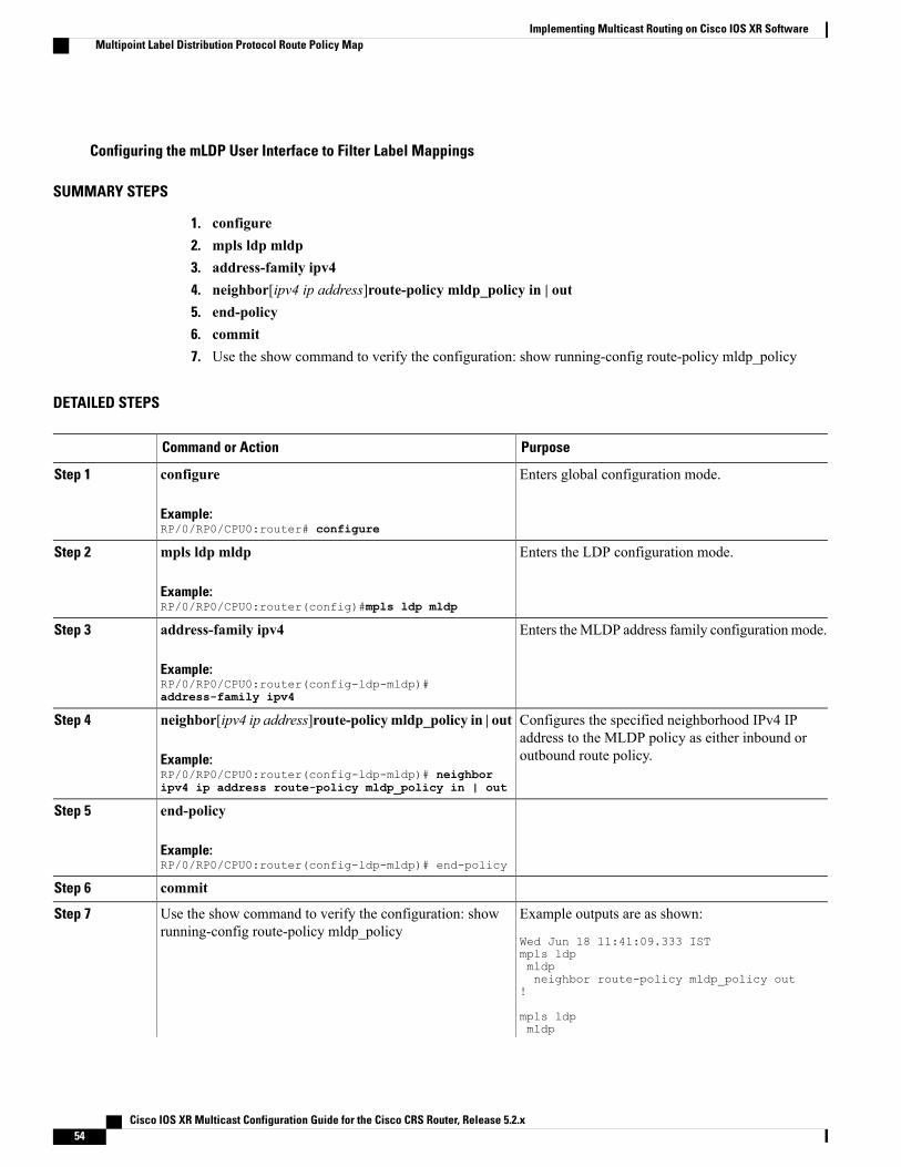
Configuring the mLDP User Interface to Filter Label Mappings
SUMMARY STEPS
1. configure2. mpls ldp mldp3. address-family ipv44. neighbor[ipv4 ip address]route-policy mldp_policy in | out5. end-policy6. commit7. Use the show command to verify the configuration: show running-config route-policy mldp_policy
DETAILED STEPS
PurposeCommand or Action
Enters global configuration mode.configure
Example:RP/0/RP0/CPU0:router# configure
Step 1
Enters the LDP configuration mode.mpls ldp mldp
Example:RP/0/RP0/CPU0:router(config)#mpls ldp mldp
Step 2
Enters theMLDP address family configurationmode.address-family ipv4
Example:RP/0/RP0/CPU0:router(config-ldp-mldp)#address-family ipv4
Step 3
Configures the specified neighborhood IPv4 IPaddress to the MLDP policy as either inbound oroutbound route policy.
neighbor[ipv4 ip address]route-policymldp_policy in | out
Example:RP/0/RP0/CPU0:router(config-ldp-mldp)# neighboripv4 ip address route-policy mldp_policy in | out
Step 4
end-policyStep 5
Example:RP/0/RP0/CPU0:router(config-ldp-mldp)# end-policy
commitStep 6
Example outputs are as shown:
Wed Jun 18 11:41:09.333 IST
Use the show command to verify the configuration: showrunning-config route-policy mldp_policy
Step 7
mpls ldpmldpneighbor route-policy mldp_policy out
!
mpls ldpmldp
Cisco IOS XR Multicast Configuration Guide for the Cisco CRS Router, Release 5.2.x54
Implementing Multicast Routing on Cisco IOS XR SoftwareMultipoint Label Distribution Protocol Route Policy Map

PurposeCommand or Actionneighbor 1.1.1.1 route-policy mldp_policyin!
Configuring the mLDP User Interface for Feature FilteringRPL policy allows the user to selectively enable features for filtering.
Configuring the mLDP User Interface for Feature Filtering - MoFRR
SUMMARY STEPS
1. configure2. mpls ldp mldp3. mofrr route-policy mldp_policy4. end5. commit6. Use the show command to verify the configuration: show running-config mpls ldp mldp
DETAILED STEPS
PurposeCommand or Action
Enters global configuration mode.configure
Example:RP/0/RP0/CPU0:router# configure
Step 1
Enters the LDP configuration mode.mpls ldp mldp
Example:RP/0/RP0/CPU0:router(config)#mpls ldp mldp
Step 2
Configures the specified feature to the MLDP policy to beallowed to be selected for filtering.
mofrr route-policy mldp_policy
Example:RP/0/RP0/CPU0:router(config-ldp-mldp)# mofrrroute-policy mldp_policy
Step 3
endStep 4
Example:RP/0/RP0/CPU0:router(config-ldp-mldp)# end
commitStep 5
Cisco IOS XR Multicast Configuration Guide for the Cisco CRS Router, Release 5.2.x 55
Implementing Multicast Routing on Cisco IOS XR SoftwareMultipoint Label Distribution Protocol Route Policy Map

PurposeCommand or Action
An example output is as shown:
Wed Jun 25 12:46:52.177 IST
Use the show command to verify the configuration:show running-config mpls ldp mldp
Step 6
mpls ldpmldpaddress-family ipv4make-before-break delay 0mofrr route-policy mldp_policyneighbor route-policy mldp_policy outneighbor 1.1.1.1 route-policy mldp_policy inneighbor 1.1.1.1 route-policy mldp_policy outneighbor 2.2.2.2 route-policy mldp_policy outrecursive-fec route-policy mldp_policy!!!
An example output showing the mLDP MoFRR output
RP/0/1/CPU0:GSR3#sh mpls mldp database opaquetype ipv4mLDP databaseLSM-ID: 0x00019 Type: P2MP Uptime: 03:25:15FEC Root : 10.0.0.1Opaque decoded : [ipv4 0.0.0.0 224.1.1.1]Features : MoFRRUpstream neighbor(s) :10.0.0.1:0 [Active] Uptime: 03:25:15Next Hop : 10.0.3.3Interface : GigabitEthernet0/2/1/1Local Label (D) : 16028
Downstream client(s):LDP 10.0.0.2:0 Uptime: 03:25:15Next Hop : 10.0.4.2Interface : GigabitEthernet0/2/1/2Remote label (D) : 16029
Configuring the mLDP User Interface for Feature Filtering - Make-before-break
SUMMARY STEPS
1. configure2. mpls ldp mldp3. address-family ipv44. make-before-break route-policy mldp_policy5. end6. commit7. Use the show command to verify the configuration: show running-config mpls ldp mldp
Cisco IOS XR Multicast Configuration Guide for the Cisco CRS Router, Release 5.2.x56
Implementing Multicast Routing on Cisco IOS XR SoftwareMultipoint Label Distribution Protocol Route Policy Map

DETAILED STEPS
PurposeCommand or Action
Enters global configuration mode.configure
Example:RP/0/RP0/CPU0:router# configure
Step 1
Enters the LDP configuration mode.mpls ldp mldp
Example:RP/0/RP0/CPU0:router(config)#mpls ldp mldp
Step 2
Enters the LDP address family configuration mode.address-family ipv4
Example:RP/0/RP0/CPU0:router(config-ldp-mldp)#address-familyipv4
Step 3
Configures the specified feature to the MLDP policyto be allowed to be selected for filtering.
make-before-break route-policy mldp_policy
Example:RP/0/RP0/CPU0:router(config-ldp-mldp-af)#make-before-break route-policy mldp_policy
Step 4
endStep 5
Example:RP/0/RP0/CPU0:router(config-ldp-mldp-af)# end
commitStep 6
An example output is as shown:
Wed Jun 25 13:05:31.303 IST
Use the show command to verify the configuration: showrunning-config mpls ldp mldp
Step 7
mpls ldpmldpaddress-family ipv4make-before-break delay 0make-before-break route-policy mldp_policy
mofrr route-policy mldp_policyneighbor route-policy mldp_policy outneighbor 1.1.1.1 route-policy mldp_policy
inneighbor 1.1.1.1 route-policy mldp_policy
outneighbor 2.2.2.2 route-policy mldp_policy
out!!!
An example output showing the mLDP make-before-break output
RP/0/1/CPU0:GSR3#sh mpls mldp database opaquetype ipv4mLDP databaseLSM-ID: 0x00019 Type: P2MP Uptime: 03:25:15
Cisco IOS XR Multicast Configuration Guide for the Cisco CRS Router, Release 5.2.x 57
Implementing Multicast Routing on Cisco IOS XR SoftwareMultipoint Label Distribution Protocol Route Policy Map

FEC Root : 10.0.0.1Opaque decoded : [ipv4 0.0.0.0 224.1.1.1]Features : MoFRR MBBUpstream neighbor(s) :10.0.0.1:0 [Active] Uptime: 03:25:15Next Hop : 10.0.3.3Interface : GigabitEthernet0/2/1/1Local Label (D) : 16028
Downstream client(s):LDP 10.0.0.2:0 Uptime: 03:25:15Next Hop : 10.0.4.2Interface : GigabitEthernet0/2/1/2Remote label (D) : 16029
Configuring the mLDP User Interface for Feature Filtering - Recursive FEC
SUMMARY STEPS
1. configure2. mpls ldp mldp3. address-family ipv44. recursive-fec route-policy rfec5. end6. commit7. Use the show command to verify the configuration: show running-config mpls ldp mldp
DETAILED STEPS
PurposeCommand or Action
Enters global configuration mode.configure
Example:RP/0/RP0/CPU0:router# configure
Step 1
Enters the LDP configuration mode.mpls ldp mldp
Example:RP/0/RP0/CPU0:router(config)#mpls ldp mldp
Step 2
Enters the LDP address family configuration mode.address-family ipv4
Example:RP/0/RP0/CPU0:router(config-ldp-mldp)#address-familyipv4
Step 3
Configures the specified feature to the MLDP policyto be allowed to be selected for filtering.
recursive-fec route-policy rfec
Example:RP/0/RP0/CPU0:router(config-ldp-mldp-af)#recursive-fec route-policy rfec
Step 4
endStep 5
Cisco IOS XR Multicast Configuration Guide for the Cisco CRS Router, Release 5.2.x58
Implementing Multicast Routing on Cisco IOS XR SoftwareMultipoint Label Distribution Protocol Route Policy Map

PurposeCommand or Action
Example:RP/0/RP0/CPU0:router(config-ldp-mldp-af)# end
commitStep 6
An example output is as shown:
Wed Jun 25 13:05:31.303 IST
Use the show command to verify the configuration: showrunning-config mpls ldp mldp
Step 7
mpls ldpmldpaddress-family ipv4make-before-break delay 0make-before-break route-policy mldp_policy
mofrr route-policy mldp_policyneighbor route-policy mldp_policy outneighbor 1.1.1.1 route-policy mldp_policy
inneighbor 1.1.1.1 route-policy mldp_policy
outneighbor 2.2.2.2 route-policy mldp_policy
outrecursive-fec route-policy rfec!!!
An example output showing the mLDP make-before-break output
RP/0/1/CPU0:GSR3#sh mpls mldp database opaquetype ipv4mLDP databaseLSM-ID: 0x00019 Type: P2MP Uptime: 03:25:15FEC Root : 10.0.0.1Opaque decoded : [ipv4 0.0.0.0 224.1.1.1]Features : MoFRR MBB RFECUpstream neighbor(s) :10.0.0.1:0 [Active] Uptime: 03:25:15Next Hop : 10.0.3.3Interface : GigabitEthernet0/2/1/1Local Label (D) : 16028
Downstream client(s):LDP 10.0.0.2:0 Uptime: 03:25:15Next Hop : 10.0.4.2Interface : GigabitEthernet0/2/1/2Remote label (D) : 16029
Limitations of Route Policy MapLimitations:
The following are the limitations of the route policy map:
• After changing the Route Policy filter to be more restrictive, the mLDP label bindings that were earlierallowed are not removed. You have to run the clear mpls ldp neighbor command to clear the mLDPdatabase.
Cisco IOS XR Multicast Configuration Guide for the Cisco CRS Router, Release 5.2.x 59
Implementing Multicast Routing on Cisco IOS XR SoftwareMultipoint Label Distribution Protocol Route Policy Map

• If you select a less restrictive filter, mLDP initiates a wildcard label request in order to install the mLDPlabel bindings that were denied earlier.
• Creating an RPL policy that allows filtering based on the recursive FEC content is not supported.
• Applying an RPL policy to configuration commands impacts the performance to a limited extent.
Next-Generation Multicast VPNNext-Generation Multicast VPN (NG-MVPN) offers more scalability for Layer 3 VPN multicast traffic. Itallows point-to-multipoint Label Switched Paths (LSP) to be used to transport the multicast traffic betweenPEs, thus allowing the multicast traffic and the unicast traffic to benefit from the advantages ofMPLS transport,such as traffic engineering and fast re-route. This technology is ideal for video transport as well as offeringmulticast service to customers of the layer 3 VPN service.
NG-MVPN supports:
• VRF Route-Import and Source-AS Extended Communities
• Upstream Multicast Hop (UMH) and Duplicate Avoidance
• Leaf AD (Type-4) and Source-Active (Type-5) BGP AD messages
• Default-MDT with mLDP P2MP trees and with Static P2MP-TE tunnels
• BGP C-multicast Routing
• RIB-based Extranet with BGP AD
• Accepting (*,G) S-PMSI announcements
• Egress-PE functionality for Ingress Replication (IR) core-trees
• Enhancements for PIM C-multicast Routing
• Migration of C-multicast Routing protocol
• PE-PE ingress replication
• Dynamic P2MP-TE tunnels
• Flexible allocation of P2MP-TE attribute-sets
• Data and partitioned MDT knobs
• Multi-instance BGP support
• SAFI-129 and VRF SAFI-2 support
• Anycast-RP using MVPN SAFI
Supported FeaturesThe following are the supported features on next generation Multicast MVPN on IOS-XR:
• GTM using MVPN SAFI
• MVPN enhancements
Cisco IOS XR Multicast Configuration Guide for the Cisco CRS Router, Release 5.2.x60
Implementing Multicast Routing on Cisco IOS XR SoftwareNext-Generation Multicast VPN

GTM Using MVPN SAFI
In a GTM procedure, special RD values are used that are created in BGP. The values used are all 0's RD. Anew knob, global-table-multicast is introduced under BGP to create the contexts for these RDs.
MVPN procedures require addition of VRF Route-Import EC, Source-AS EC, and so on to the VPNv4 routesoriginated by PEs. With GTM, there are no VRFs and no VPNv4 routes. The multicast specific attributeshave to be added to Global table iBGP routes (either SAFI-1 or SAFI-2). These routes are learnt througheBGP (from a CE) or from a different Unicast routing protocol.
• The single forwarder selection is not supported for GTM.
• Route Targets:With GTM, there are no VRFs, hence the export and import RTs configured underVRFs are not reliable. ForMVPNSAFI routes, RT(s) must be attached. Export and import Route Targetsconfiguration under multicast routing is supported. These are the RTs used for Type 1, 3, and 5 routes.MVPN SAFI routes received without any RTs will not be accepted by an XR PE.
• Core-Tree Protocols: mLDP, P2MP-TE (static and dynamic), and IR core-trees are supported.
• C-multicast Routing: PIM and BGP C-multicast routing are supported.
•MDTModels:Default-MDT and Partitioned-MDTmodels are supported. Data-MDT is supported, withits various options (threshold zero, immediate-switch, starg s-pmsi, and so on.)
The configuration is as shown below for Ingress or Egress PEs:
multicast-routingaddress-family [ipv4| ipv6]mdt source Loopback0mdt default <MLDP | P2MP-TE | ingress-replication>mdt partitioned <MLDP | P2MP-TE | ingress-replication>bgp auto-discovery [mldp | p2mp-te | ingress-replication]export-rt <value>import-rt <value>!!!
The mdt default, mdt partitioned, and the bgp auto-discovery configurations, are present under VRFs,however, with GTM Using MVPN SAFI, the configurations are reflected in global table as well.
Note
router bgp 100address-family [ipv4| ipv6] mvpnglobal-table-multicast!!The global-table-multicast configuration enables processing of All-0's RD.
MVPN enhancements
• Anycast RP using MVPN SAFI This procedure uses Type-5 MVPN SAFI routes to convey sourceinformation between RPs. Use this method to support Anycast-RP, instead of usingMSDP. This supportsAnycast-RP for both IPv4 and IPv6. Currently, Anycast-RP is supported for IPv4 (using MSDP). BGPmethod is supported for GTM using MVPN SAFI and MVPNs.
The configuration is as shown below for Ingress or Egress PEs:
multicast-routing
Cisco IOS XR Multicast Configuration Guide for the Cisco CRS Router, Release 5.2.x 61
Implementing Multicast Routing on Cisco IOS XR SoftwareSupported Features

address-family [ipv4| ipv6]bgp auto-discovery [mldp | p2mp-te | ingress-replication]anycast-rp route-policy <anycast-policy>!!vrf <name>address-family [ipv4| ipv6]bgp auto-discovery [mldp | p2mp-te | ingress-replication]anycast-rp route-policy <anycast-policy>
!!!
The route-policy for anycast RP is as defined below.
route-policy anycast-policyif destination in group-set thenpass
endifend-policy!
The group-set command is a XR prefix-set configuration, an example is as shown below:
prefix-set group-set227.1.1.1/32end-setAn alternate way of performing this procedure is using export-rt and import-rt configuration commands.Here, the router announcing the Type-5 route must have the export-rt configured, and the router learningthe source must have the import-rt configured.
multicast-routingvrf oneaddress-family ipv4export-rt 51.52.53.54:0 <<<<<<<interface all enablebgp auto-discovery ingress-replicationinter-asanycast-rp <<<<<<<<<!mdt partitioned ingress-replication!!!
multicast-routingvrf oneaddress-family ipv4import-rt 51.52.53.54:0 <<<<<<<<<<<interface all enablebgp auto-discovery ingress-replicationinter-asanycast-rp <<<<<<<<<<<<<<<!mdt partitioned ingress-replication!!!
• Receiver-only VRFs Supports receiver-only VRFs. In receiver-only VRFs, the I-PMSI or theMS-PMSIroutes do not carry any tunnel information. This reduces the state on the P routers.
The configuration is as shown below:
multicast-routingaddress-family [ipv4| ipv6]bgp auto-discovery [mldp | p2mp-te | ingress-replication]
Cisco IOS XR Multicast Configuration Guide for the Cisco CRS Router, Release 5.2.x62
Implementing Multicast Routing on Cisco IOS XR SoftwareSupported Features

receiver-site!!vrf <name>address-family [ipv4| ipv6]bgp auto-discovery [mldp | p2mp-te | ingress-replication]receiver-site
!!!
• RPF vector insertion inGlobal TableUnifiedMPLS deployments, for example, UMMT or EPNmodelface issues, where some of the PEs do not support the enhancement procedures. In this case, to retainBGP-free core in the Ingress and Egress segments, the PEs send PIM Joins with RPF-proxy vector. Tointeroperate in such scenarios, the XR border acts as a transit node for RPF vector. This can be used inother cases of BGP-free core as well. The RPF-vector support is only for GTM and not for MVPNs(Inter-AS Option B). Support is enabled for the RPF-vector address-family being same as the MulticastJoin address-family.
IOS-XR supports termination of RPF vectors as well as acts as a transit router for RPFvector. The termination of RPF vectors was introduced from release 4.3.1, however, thesupport for acting as a transit router existed in earlier releases as well.
Note
The configuration is as shown below:
router pimaddress-family [ipv4|ipv6]rpf-vector!!
PE-PE Ingress ReplicationThe ingress PE replicates a C-multicast data packet belonging to a particular MVPN and sends a copy to allor a subset of the PEs that belong to theMVPN. A copy of the packet is tunneled to a remote PE over a UnicastTunnel to the remote PE.
IR-MDT represents a tunnel that uses IR as the forwarding method. It is usually, one IR-MDT per VRF, withmultiple labeled switch paths (LSP) under the tunnel.
When PIM learns of Joins over the MDT (using either PIM or BGP C-multicast Routing), it downloads IPS,G routes to the VRF table inMRIB, with IR-MDT forwarding interfaces. Each IR-MDT forwarding interfacehas a LSM-ID allocated by PIM. Currently, LSM-ID is managed by mLDP and can range from 0 to 0xFFFFF(20-bits). For IR, the LSM-ID space is partitioned between mLDP and IR. For IR tunnels, the top (20th) bitis always be set, leading to a range of 0x80000 to 0xFFFFF. mLDP’s limit is 0 to 0x7FFFF.
Multicast IRBMulticast IRB provides the ability to route multicast packets between a bridge group and a routed interfaceusing a bridge-group virtual interface (BVI). It can be enabled with multicast-routing. THE BVI is a virtualinterface within the router that acts like a normal routed interface. For details about BVI, refer Cisco IOS XRInterface and Hardware Component Configuration Guide for the Cisco CRS Router
Cisco IOS XR Multicast Configuration Guide for the Cisco CRS Router, Release 5.2.x 63
Implementing Multicast Routing on Cisco IOS XR SoftwarePE-PE Ingress Replication

BV interfaces are added to the existing VRF routes and integrated with the replication slot mask. After thisintegration, the traffic coming from a VRF BVI is forwarded to the VPN.
Supported bridge port types• Bundles
• Satellites
• EFPs (physical, vlans, etc)
• Pseudowires
Restrictions• Supported only on Ethernet line cards and enhanced ethernet line cards.
• Support only for IPv4
• Supports IGMP snooping
Multicast IRBThe CE-PE is collapsed into 1 router (IRB) and IGMP snooping is enabled on the BVIs.
BVI type is included in a multicast VRF. After the BVI slot mask is included in the VRF route slot mask, thetraffic from the VRF BVI is forwarded to the VPN/ core.
Multicast Source Discovery ProtocolMulticast Source Discovery Protocol (MSDP) is a mechanism to connect multiple PIM sparse-mode domains.MSDP allows multicast sources for a group to be known to all rendezvous points (RPs) in different domains.Each PIM-SM domain uses its own RPs and need not depend on RPs in other domains.
An RP in a PIM-SM domain has MSDP peering relationships with MSDP-enabled routers in other domains.Each peering relationship occurs over a TCP connection, which is maintained by the underlying routingsystem.
MSDP speakers exchange messages called Source Active (SA) messages. When an RP learns about a localactive source, typically through a PIM register message, the MSDP process encapsulates the register in anSAmessage and forwards the information to its peers. Themessage contains the source and group informationfor the multicast flow, as well as any encapsulated data. If a neighboring RP has local joiners for the multicastgroup, the RP installs the S, G route, forwards the encapsulated data contained in the SA message, and sendsPIM joins back towards the source. This process describes how amulticast path can be built between domains.
Although you should configure BGP or Multiprotocol BGP for optimal MSDP interdomain operation,this is not considered necessary in the Cisco IOS XR Software implementation. For information abouthow BGP or Multiprotocol BGPmay be used with MSDP, see the MSDP RPF rules listed in the MulticastSource Discovery Protocol (MSDP), Internet Engineering Task Force (IETF) Internet draft.
Note
Cisco IOS XR Multicast Configuration Guide for the Cisco CRS Router, Release 5.2.x64
Implementing Multicast Routing on Cisco IOS XR SoftwareMulticast Source Discovery Protocol

VRF-aware MSDPVRF (VPN Routing and Forwarding) -aware MSDP enables MSDP to function in the VRF context. This inturn, helps the user to locate the PIM (protocol Independent Multicast) RP on the Provider Edge and useMSDP for anycast-RP.
MSDP needs to be VRF-aware when:
• Anycast-RP is deployed in an MVPN (Multicast MVPN) in such a manner that one or more PIM RPsin the anycast-RP set are located on a PE. In such a deployment, MSDP needs to operate in the VRFcontext on the PE.
• The PIM RP is deployed in an MVPN in such a manner that it is not on a PE and when the customermulticast routing type for theMVPN is BGP and the PEs have suppress-shared-tree-join option configured.In this scenario, there is no PE-shared tree link, so traffic may stop at the RP and it does not flow toother MVPN sites. An MSDP peering between the PIM RP and one or more PEs resolves the issue.
Multicast Nonstop ForwardingThe Cisco IOS XR Software nonstop forwarding (NSF) feature for multicast enhances high availability (HA)of multicast packet forwarding. NSF prevents hardware or software failures on the control plane from disruptingthe forwarding of existing packet flows through the router.
The contents of the Multicast Forwarding Information Base (MFIB) are frozen during a control plane failure.Subsequently, PIM attempts to recover normal protocol processing and state before the neighboring routerstime out the PIM hello neighbor adjacency for the problematic router. This behavior prevents the NSF-capablerouter from being transferred to neighbors that will otherwise detect the failure through the timed-out adjacency.Routes in MFIB are marked as stale after entering NSF, and traffic continues to be forwarded (based on thoseroutes) until NSF completion. On completion, MRIB notifies MFIB and MFIB performs a mark-and-sweepto synchronize MFIB with the current MRIB route information.
Nonstop forwarding is not supported for PIM bidirectional routes. If a PIM or MRIB failure (includingRP failover) happens with multicast-routing NSF enabled, PIM bidirectional routes in the MFIBs arepurged immediately and forwarding on these routes stops. Routes are reinstalled and forwardingrecommences after NSF recovery has ended. This affects only bidirectional routes. PIM-SM and PIM-SSMroutes are forwarded with NSF during the failure. This exception is designed to prevent possible multicastrouting loops from forming when the control plane is not able to participate in the BiDir DesignatedForwarder election.
Note
Multicast Configuration SubmodesCisco IOS XR Software moves control plane CLI configurations to protocol-specific submodes to providemechanisms for enabling, disabling, and configuring multicast features on a large number of interfaces.
Cisco IOSXR Software allows you to issue most commands available under submodes as one single commandstring from the global or XR config mode.
Cisco IOS XR Multicast Configuration Guide for the Cisco CRS Router, Release 5.2.x 65
Implementing Multicast Routing on Cisco IOS XR SoftwareMulticast Nonstop Forwarding

For example, the ssm command could be executed from the multicast-routing configuration submode likethis:
RP/0/RP0/CPU0:router(config)# multicast-routingRP/0/RP0/CPU0:router(config-mcast-ipv4)# ssm range
Alternatively, you could issue the same command from the global or XR config mode like this:
RP/0/RP0/CPU0:router(config)# multicast-routing ssm range
The following multicast protocol-specific submodes are available through these configuration submodes:
Multicast-Routing Configuration SubmodeWhen you issue themulticast-routing ipv4 or multicast-routing ipv6 command, all default multicastcomponents (PIM, IGMP, MLD, MFWD, and MRIB) are automatically started, and the CLI prompt changesto “config-mcast-ipv4” or “config-mcast-ipv6”, indicating that you have enteredmulticast-routing configurationsubmode.
PIM Configuration SubmodeWhen you issue the router pim command, the CLI prompt changes to “config-pim-ipv4,” indicating that youhave entered the default pim address-family configuration submode.
To enter pim address-family configuration submode for IPv6, type the address-family ipv6 keyword togetherwith the router pim command before pressing Enter.
IGMP Configuration SubmodeWhen you issue the router igmp command, the CLI prompt changes to “config-igmp,” indicating that youhave entered IGMP configuration submode.
MLD Configuration SubmodeWhen you issue the router mld command, the CLI prompt changes to “config-mld,” indicating that you haveentered MLD configuration submode.
MSDP Configuration SubmodeWhen you issue the router msdp command, the CLI prompt changes to “config-msdp,” indicating that youhave entered router MSDP configuration submode.
Understanding Interface Configuration InheritanceCisco IOS XR Software allows you to configure commands for a large number of interfaces by applyingcommand configuration within a multicast routing submode that could be inherited by all interfaces. Tooverride the inheritance mechanism, you can enter interface configuration submode and explicitly enter adifferent command parameter.
Cisco IOS XR Multicast Configuration Guide for the Cisco CRS Router, Release 5.2.x66
Implementing Multicast Routing on Cisco IOS XR SoftwareUnderstanding Interface Configuration Inheritance

For example, in the following configuration you could quickly specify (under router PIM configurationmode)that all existing and new PIM interfaces on your router will use the hello interval parameter of 420 seconds.However, Packet-over-SONET/SDH (POS) interface 0/1/0/1 overrides the global interface configuration anduses the hello interval time of 210 seconds.
RP/0/RP0/CPU0:router(config)# router pimRP/0/RP0/CPU0:router(config-pim-default-ipv4)# hello-interval 420RP/0/RP0/CPU0:router(config-pim-default-ipv4)# interface pos 0/1/0/1RP/0/RP0/CPU0:router(config-pim-ipv4-if)# hello-interval 210
The following is a listing of commands (specified under the appropriate router submode) that use the inheritancemechanism:
router pimdr-priorityhello-intervaljoin-prune-interval
multicast-routingversionquery-intervalquery-max-response-timeexplicit-tracking
router mldinterface all disableversionquery-intervalquery-max-response-timeexplicit-tracking
router msdpconnect-sourcesa-filterfilter-sa-request listremote-asttl-threshold
Understanding Interface Configuration Inheritance DisablementAs stated elsewhere, Cisco IOS XR Software allows you to configure multiple interfaces by applyingconfigurations within a multicast routing submode that can be inherited by all interfaces.
To override the inheritance feature on specific interfaces or on all interfaces, you can enter the address-familyIPv4 or IPv6 submode of multicast routing configuration mode, and enter the interface-inheritance disablecommand together with the interface type interface-path-id or interface all command. This causes PIM orIGMP protocols to disallow multicast routing and to allow only multicast forwarding on those interfacesspecified. However, routing can still be explicitly enabled on specified individual interfaces.
The following configuration disables multicast routing interface inheritance under PIM and IGMP generally,although forwarding enablement continues. The example shows interface enablement under IGMP ofGigabitEthernet 0/6/0/3:
RP/0/RP0/CPU0:router# multicast-routing address-family ipv4RP/0/RP0/CPU0:router(config-mcast-default-ipv4)# interface all enableRP/0/RP0/CPU0:router(config-mcast-default-ipv4)# interface-inheritance disable
!
!
Cisco IOS XR Multicast Configuration Guide for the Cisco CRS Router, Release 5.2.x 67
Implementing Multicast Routing on Cisco IOS XR SoftwareUnderstanding Interface Configuration Inheritance Disablement

RP/0/RP0/CPU0:router(config)# router igmpRP/0/RP0/CPU0:router(config-igmp)# vrf defaultRP/0/RP0/CPU0:router(config-igmp)# interface GigabitEthernet0/6/0/0RP/0/RP0/CPU0:router(config-igmp-name-if)# router enable
For related information, see Understanding Enabling and Disabling Interfaces, on page 68
Understanding Enabling and Disabling InterfacesWhen the Cisco IOS XR Software multicast routing feature is configured on your router, by default, nointerfaces are enabled.
To enable multicast routing and protocols on a single interface or multiple interfaces, you must explicitlyenable interfaces using the interface command in multicast routing configuration mode.
To set up multicast routing on all interfaces, enter the interface all command in multicast routing configurationmode. For any interface to be fully enabled for multicast routing, it must be enabled specifically (or be default)in multicast routing configurationmode, and it must not be disabled in the PIM and IGMP/MLD configurationmodes.
For example, in the following configuration, all interfaces are explicitly configured from multicast routingconfiguration submode:
RP/0/RP0/CPU0:router(config)# multicast-routingRP/0/RP0/CPU0:router(config-mcast)# interface all enable
To disable an interface that was globally configured from the multicast routing configuration submode, enterinterface configuration submode, as illustrated in the following example:
RP/0/RP0/CPU0:router(config-mcast)# interface GigabitEthernet0pos 0/1/0/0RP/0/RP0/CPU0:router(config-mcast-default-ipv4-if)# disable
Multicast Routing Information BaseThe Multicast Routing Information Base (MRIB) is a protocol-independent multicast routing table thatdescribes a logical network in which one or more multicast routing protocols are running. The tables containgeneric multicast routes installed by individual multicast routing protocols. There is anMRIB for every logicalnetwork (VPN) in which the router is configured. MRIBs do not redistribute routes among multicast routingprotocols; they select the preferred multicast route from comparable ones, and they notify their clients ofchanges in selected attributes of any multicast route.
Multicast Forwarding Information BaseMulticast Forwarding Information Base (MFIB) is a protocol-independent multicast forwarding system thatcontains unique multicast forwarding entries for each source or group pair known in a given network. Thereis a separate MFIB for every logical network (VPN) in which the router is configured. Each MFIB entryresolves a given source or group pair to an incoming interface (IIF) for reverse forwarding (RPF) checkingand an outgoing interface list (olist) for multicast forwarding.
Cisco IOS XR Multicast Configuration Guide for the Cisco CRS Router, Release 5.2.x68
Implementing Multicast Routing on Cisco IOS XR SoftwareUnderstanding Enabling and Disabling Interfaces

MSDP MD5 Password AuthenticationMSDP MD5 password authentication is an enhancement to support Message Digest 5 (MD5) signatureprotection on a TCP connection between twoMulticast Source Discovery Protocol (MSDP) peers. This featureprovides added security by protecting MSDP against the threat of spoofed TCP segments being introducedinto the TCP connection stream.
MSDPMD5 password authentication verifies each segment sent on the TCP connection betweenMSDP peers.The password clear command is used to enableMD5 authentication for TCP connections between twoMSDPpeers. When MD5 authentication is enabled between two MSDP peers, each segment sent on the TCPconnection between the peers is verified.
MSDP MD5 authentication must be configured with the same password on both MSDP peers to enablethe connection between them. The 'password encrypted' command is used only for applying the storedrunning configuration. Once you configure theMSDPMD5 authentication, you can restore the configurationusing this command.
Note
MSDP MD5 password authentication uses an industry-standard MD5 algorithm for improved reliability andsecurity.
How to Implement Multicast RoutingThis section contains instructions for both building a basic multicast configuration, as well as optional tasksto help you to optimize, debug, and discover the routers in your multicast network.
Configuring PIM-SM and PIM-SSM
SUMMARY STEPS
1. configure2. multicast-routing [address-family {ipv4 | ipv6}]3. interface all enable4. exit5. Use router { igmp} for IPv4 hosts or use router {mld} for IPv66. version {1 | 2 | 3} for IPv4 (IGMP) hosts or version {1 | 2} for IPv6 (MLD) hosts.7. commit8. show pim [ipv4 | ipv6] group-map [ip-address-name] [info-source]9. show pim [vrf vrf-name] [ipv4 | ipv6] topology [source-ip-address [group-ip-address] | entry-flag flag
| interface-flag | summary] [route-count]
Cisco IOS XR Multicast Configuration Guide for the Cisco CRS Router, Release 5.2.x 69
Implementing Multicast Routing on Cisco IOS XR SoftwareMSDP MD5 Password Authentication

DETAILED STEPS
PurposeCommand or Action
configureStep 1
Enters multicast routing configuration mode.multicast-routing [address-family {ipv4 | ipv6}]Step 2
Example:
RP/0/RP0/CPU0:router(config)#
• The following multicast processes are started: MRIB,MFWD, PIM, IGMP, and MLD.
• For IPv4, IGMP version 3 is enabled by default; for IPv6,MLD version 1 is enabled by default.
multicast-routing
Enables multicast routing and forwarding on all new andexisting interfaces.
interface all enable
Example:
RP/0/RP0/CPU0:router(config-mcast-ipv4)#interface all enable
Step 3
Exits multicast routing configuration mode, and returns therouter to the source configuration mode.
exit
Example:
RP/0/RP0/CPU0:router(config-mcast-ipv4)# exit
Step 4
(Optional) Enters router IGMP configuration mode (for IPv4hosts), or enters router MLD configuration mode (for IPv6hosts).
Use router { igmp} for IPv4 hosts or use router {mld} for IPv6
Example:
RP/0/RP0/CPU0:router(config)# router igmp
Step 5
RP/0/RP0/CPU0:router(config)# router mld
(Optional) Selects the IGMP or MLD version that the routerinterface uses.
version {1 | 2 | 3} for IPv4 (IGMP) hosts or version{1 | 2} for IPv6 (MLD) hosts.
Step 6
Example:
RP/0/RP0/CPU0:router(config-igmp)# version 3RP/0/RP0/CPU0:router(config-mld)# version 2
• The version range for IGMP is 1-3; the range for MLD is1-2.
• The default for IGMP is version 3; the default for MLDis version 1.
• Host receivers must support IGMPv3 for PIM-SSMoperation.
• If this command is configured in router IGMP or routerMLD configuration mode, parameters are inherited by allnew and existing interfaces. You can override theseparameters on individual interfaces from interfaceconfiguration mode.
commitStep 7
Cisco IOS XR Multicast Configuration Guide for the Cisco CRS Router, Release 5.2.x70
Implementing Multicast Routing on Cisco IOS XR SoftwareConfiguring PIM-SM and PIM-SSM

PurposeCommand or Action
(Optional) Displays group-to-PIM mode mapping.show pim [ipv4 | ipv6] group-map [ip-address-name][info-source]
Step 8
Example:
RP/0/RP0/CPU0:router# show pim ipv4 group-map
(Optional) Displays PIM topology table information for aspecific group or all groups.
show pim [vrf vrf-name] [ipv4 | ipv6] topology[source-ip-address [group-ip-address] | entry-flagflag | interface-flag | summary] [route-count]
Step 9
Example:
RP/0/RP0/CPU0:router# show pim topology
Configuring Native PIM BIDIRPerform these steps to configure native PIM BIDIR.
SUMMARY STEPS
1. configure2. ipv4 access-list name3. [sequence-number] permit source [source-wildcard]4. interface type interface-path-id5. {ipv4 | ipv6} address address mask6. router ospf 1007. nsf cisco8. area area_id9. interface type interface-path-id10. multicast-routing [address-family {ipv4 | ipv6}]11. nsf12. rate-per-route13. interface all enable14. router pim [address-family {ipv4 | ipv6}]15. rp-address ip-address [group-access-list] [bidir]16. commit
Cisco IOS XR Multicast Configuration Guide for the Cisco CRS Router, Release 5.2.x 71
Implementing Multicast Routing on Cisco IOS XR SoftwareConfiguring Native PIM BIDIR
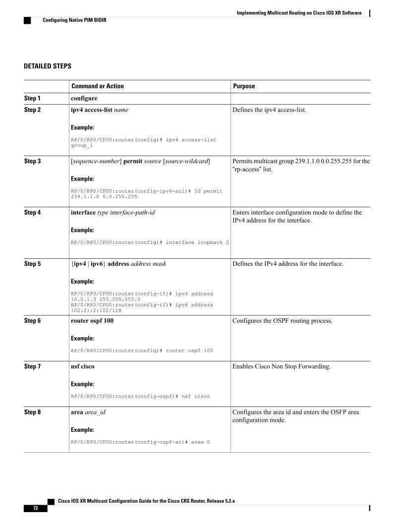
DETAILED STEPS
PurposeCommand or Action
configureStep 1
Defines the ipv4 access-list.ipv4 access-list name
Example:
RP/0/RP0/CPU0:router(config)# ipv4 access-list
Step 2
group_1
Permits multicast group 239.1.1.0 0.0.255.255 for the“rp-access” list.
[sequence-number] permit source [source-wildcard]
Example:
RP/0/RP0/CPU0:router(config-ipv4-acl)# 10 permit
Step 3
239.1.1.0 0.0.255.255
Enters interface configuration mode to define theIPv4 address for the interface.
interface type interface-path-id
Example:
RP/0/RP0/CPU0:router(config)# interface loopback 2
Step 4
Defines the IPv4 address for the interface.{ipv4 | ipv6} address address mask
Example:
RP/0/RP0/CPU0:router(config-if)# ipv4 address
Step 5
10.0.1.3 255.255.255.0RP/0/RP0/CPU0:router(config-if)# ipv6 address102:2::2:102/128
Configures the OSPF routing process.router ospf 100
Example:
RP/0/RP0/CPU0:router(config)# router ospf 100
Step 6
Enables Cisco Non Stop Forwarding.nsf cisco
Example:
RP/0/RP0/CPU0:router(config-ospf)# nsf cisco
Step 7
Configures the area id and enters the OSFP areaconfiguration mode.
area area_id
Example:
RP/0/RP0/CPU0:router(config-ospf-ar)# area 0
Step 8
Cisco IOS XR Multicast Configuration Guide for the Cisco CRS Router, Release 5.2.x72
Implementing Multicast Routing on Cisco IOS XR SoftwareConfiguring Native PIM BIDIR

PurposeCommand or Action
Enters interface configuration mode to define theIPv4 address for the interface.
interface type interface-path-id
Example:
RP/0/RP0/CPU0:router(config-ospf-ar)# interface
Step 9
Similarly, configure multiple interfaces fora multicast configuration.
Note
Bundler-Ether1
Enters multicast routing configuration mode.multicast-routing [address-family {ipv4 | ipv6}]
Example:
RP/0/RP0/CPU0:router(config)# multicast-routing
Step 10
address-family ipv4RP/0/RP0/CPU0:router(config)# multicast-routingaddress-family ipv6
Configures global multicast Cisco Non StopForwarding.
nsf
Example:
RP/0/RP0/CPU0:router(config-mcast-default-ipv4)#
Step 11
nsf
Enables or disabled per (S, G) rate calculation.rate-per-route
Example:
RP/0/RP0/CPU0:router(config-mcast-default-ipv4)#
Step 12
rate-per-route
Enables IP multicast for interfaces.interface all enable
Example:
RP/0/RP0/CPU0:router(config-mcast-default-ipv4)#
Step 13
interface all enable
Enters PIM configuration mode, or PIMaddress-family configuration submode.
router pim [address-family {ipv4 | ipv6}]
Example:
RP/0/RP0/CPU0:router(config)# router pim
Step 14
address-family ipv4
Configures the Rendezvous point and assigns an RPto multicast groups.
rp-address ip-address [group-access-list] [bidir]
Example:
RP/0/RP0/CPU0:router(config-pim-default-ipv4)#
Step 15
The RPmechanism can be static, auto-rp, orBSR.
Note
rp-address 172.16.6.22 group_1 bidir• If you specify a group-access-list-numbervalue, you must configure that access list usingthe ipv4 access-list command.
Cisco IOS XR Multicast Configuration Guide for the Cisco CRS Router, Release 5.2.x 73
Implementing Multicast Routing on Cisco IOS XR SoftwareConfiguring Native PIM BIDIR

PurposeCommand or Action
commitStep 16
Configuring MVPN GRE BIDIRPerform these steps to configure MVPN GRE BIDIR.
Cisco IOS XR Multicast Configuration Guide for the Cisco CRS Router, Release 5.2.x74
Implementing Multicast Routing on Cisco IOS XR SoftwareConfiguring MVPN GRE BIDIR
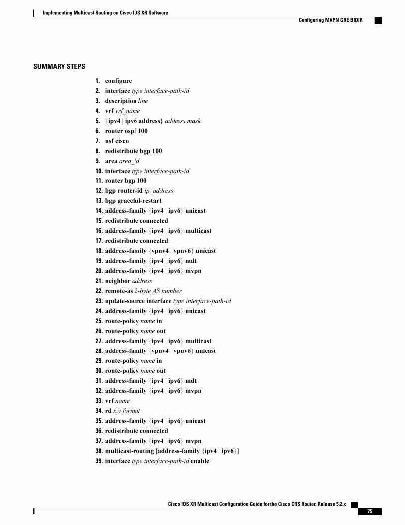
SUMMARY STEPS
1. configure2. interface type interface-path-id3. description line4. vrf vrf_name5. {ipv4 | ipv6 address} address mask6. router ospf 1007. nsf cisco8. redistribute bgp 1009. area area_id10. interface type interface-path-id11. router bgp 10012. bgp router-id ip_address13. bgp graceful-restart14. address-family {ipv4 | ipv6} unicast15. redistribute connected16. address-family {ipv4 | ipv6}multicast17. redistribute connected18. address-family {vpnv4 | vpnv6} unicast19. address-family {ipv4 | ipv6}mdt20. address-family {ipv4 | ipv6}mvpn21. neighbor address22. remote-as 2-byte AS number23. update-source interface type interface-path-id24. address-family {ipv4 | ipv6} unicast25. route-policy name in26. route-policy name out27. address-family {ipv4 | ipv6}multicast28. address-family {vpnv4 | vpnv6} unicast29. route-policy name in30. route-policy name out31. address-family {ipv4 | ipv6}mdt32. address-family {ipv4 | ipv6}mvpn33. vrf name34. rd x.y format35. address-family {ipv4 | ipv6} unicast36. redistribute connected37. address-family {ipv4 | ipv6}mvpn38. multicast-routing [address-family {ipv4 | ipv6}]39. interface type interface-path-id enable
Cisco IOS XR Multicast Configuration Guide for the Cisco CRS Router, Release 5.2.x 75
Implementing Multicast Routing on Cisco IOS XR SoftwareConfiguring MVPN GRE BIDIR

40. nsf41. mdt source interface-path-id42. interface all enable43. vrf name44. address-family {ipv4 | ipv6}45. bgp auto-discovery pim46. mdt default {ipv4 | ipv6} ipaddress partitioned bidir ipaddress47. interface all enable48. router pim [address-family {ipv4 | ipv6}]49. rp-address ip-address50. vrf name51. address-family {ipv4 | ipv6}52. rp-address ip-address [group-access-list] [bidir]53. commit
DETAILED STEPS
PurposeCommand or Action
configureStep 1
Enters interface configuration mode to define theIPv4 address for the interface.
interface type interface-path-id
Example:
RP/0/RP0/CPU0:router(config)# interface loopback 1
Step 2
Enters interface configuration mode to define theIPv4 address for the interface.
description line
Example:
RP/0/RP0/CPU0:router(config-if)# description
Step 3
"loopback interface on PE1"
Sets VRF in which the interface operates.vrf vrf_name
Example:
RP/0/RP0/CPU0:router(config-if)# vrf vrf1
Step 4
Defines the IPv4 address for the interface.{ipv4 | ipv6 address} address mask
Example:
RP/0/RP0/CPU0:router(config-if)# ipv4 address
Step 5
10.0.1.3 255.255.255.0RP/0/RP0/CPU0:router(config-if)# ipv6 address101:101::101:101/128
Cisco IOS XR Multicast Configuration Guide for the Cisco CRS Router, Release 5.2.x76
Implementing Multicast Routing on Cisco IOS XR SoftwareConfiguring MVPN GRE BIDIR

PurposeCommand or Action
Configures the OSPF routing process.router ospf 100
Example:
RP/0/RP0/CPU0:router(config)# router ospf 100
Step 6
Enables Cisco Non Stop Forwarding.nsf cisco
Example:
RP/0/RP0/CPU0:router(config-ospf)# nsf cisco
Step 7
Redistributes information from another routingprotocol such as BGP.
redistribute bgp 100
Example:
RP/0/RP0/CPU0:router(config-ospf)# redistribute bgp
Step 8
100
Configures the area id and enters the OSFP areaconfiguration mode.
area area_id
Example:
RP/0/RP0/CPU0:router(config-ospf-ar)# area 0
Step 9
Enters interface configuration mode to define theIPv4 address for the interface.
interface type interface-path-id
Example:
RP/0/RP0/CPU0:router(config)# interface loopback 1
Step 10
Similarly, configure multiple interfaces fora multicast configuration.
Note
Configures the BGP routing process.router bgp 100
Example:
RP/0/RP0/CPU0:router(config)# router bgp 100
Step 11
Configures the router-id for the BGP protocol.bgp router-id ip_address
Example:
RP/0/RP0/CPU0:router(config-bgp)# bgp router-id
Step 12
12.33.42.34
Enables graceful-restart support for the BGPprotocol.
bgp graceful-restart
Example:
RP/0/RP0/CPU0:router(config-bgp)# bgp
Step 13
graceful-restart
Cisco IOS XR Multicast Configuration Guide for the Cisco CRS Router, Release 5.2.x 77
Implementing Multicast Routing on Cisco IOS XR SoftwareConfiguring MVPN GRE BIDIR
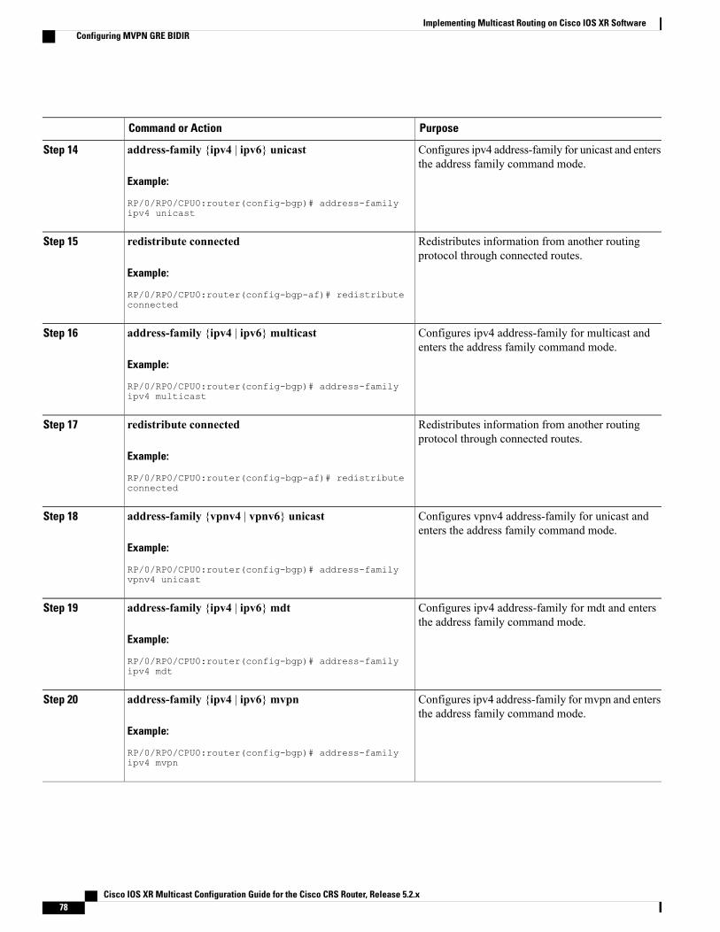
PurposeCommand or Action
Configures ipv4 address-family for unicast and entersthe address family command mode.
address-family {ipv4 | ipv6} unicast
Example:
RP/0/RP0/CPU0:router(config-bgp)# address-family
Step 14
ipv4 unicast
Redistributes information from another routingprotocol through connected routes.
redistribute connected
Example:
RP/0/RP0/CPU0:router(config-bgp-af)# redistribute
Step 15
connected
Configures ipv4 address-family for multicast andenters the address family command mode.
address-family {ipv4 | ipv6}multicast
Example:
RP/0/RP0/CPU0:router(config-bgp)# address-family
Step 16
ipv4 multicast
Redistributes information from another routingprotocol through connected routes.
redistribute connected
Example:
RP/0/RP0/CPU0:router(config-bgp-af)# redistribute
Step 17
connected
Configures vpnv4 address-family for unicast andenters the address family command mode.
address-family {vpnv4 | vpnv6} unicast
Example:
RP/0/RP0/CPU0:router(config-bgp)# address-family
Step 18
vpnv4 unicast
Configures ipv4 address-family for mdt and entersthe address family command mode.
address-family {ipv4 | ipv6}mdt
Example:
RP/0/RP0/CPU0:router(config-bgp)# address-family
Step 19
ipv4 mdt
Configures ipv4 address-family for mvpn and entersthe address family command mode.
address-family {ipv4 | ipv6}mvpn
Example:
RP/0/RP0/CPU0:router(config-bgp)# address-family
Step 20
ipv4 mvpn
Cisco IOS XR Multicast Configuration Guide for the Cisco CRS Router, Release 5.2.x78
Implementing Multicast Routing on Cisco IOS XR SoftwareConfiguring MVPN GRE BIDIR
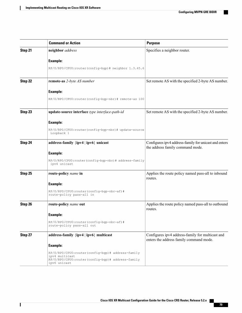
PurposeCommand or Action
Specifies a neighbor router.neighbor address
Example:
RP/0/RP0/CPU0:router(config-bgp)# neighbor 1.3.45.6
Step 21
Set remote AS with the specified 2-byte AS number.remote-as 2-byte AS number
Example:
RP/0/RP0/CPU0:router(config-bgp-nbr)# remote-as 100
Step 22
Set remote AS with the specified 2-byte AS number.update-source interface type interface-path-id
Example:
RP/0/RP0/CPU0:router(config-bgp-nbr)# update-source
Step 23
Loopback 1
Configures ipv4 address-family for unicast and entersthe address family command mode.
address-family {ipv4 | ipv6} unicast
Example:
RP/0/RP0/CPU0:router(config-bgp-nbr)# address-family
Step 24
ipv4 unicast
Applies the route policy named pass-all to inboundroutes.
route-policy name in
Example:
RP/0/RP0/CPU0:router(config-bgp-nbr-af)#
Step 25
route-policy pass-all in
Applies the route policy named pass-all to outboundroutes.
route-policy name out
Example:
RP/0/RP0/CPU0:router(config-bgp-nbr-af)#
Step 26
route-policy pass-all out
Configures ipv4 address-family for multicast andenters the address family command mode.
address-family {ipv4 | ipv6}multicast
Example:
RP/0/RP0/CPU0:router(config-bgp)# address-family
Step 27
ipv4 multicastRP/0/RP0/CPU0:router(config-bgp)# address-familyipv6 unicast
Cisco IOS XR Multicast Configuration Guide for the Cisco CRS Router, Release 5.2.x 79
Implementing Multicast Routing on Cisco IOS XR SoftwareConfiguring MVPN GRE BIDIR

PurposeCommand or Action
Configures vpnv4 address-family for unicast andenters the address family command mode.
address-family {vpnv4 | vpnv6} unicast
Example:
RP/0/RP0/CPU0:router(config-bgp)# address-family
Step 28
vpnv4 unicastRP/0/RP0/CPU0:router(config-bgp)# address-familyvpnv6 unicast
Applies the route policy named pass-all to inboundroutes.
route-policy name in
Example:
RP/0/RP0/CPU0:router(config-bgp-nbr-af)#
Step 29
route-policy pass-all in
Applies the route policy named pass-all to outboundroutes.
route-policy name out
Example:
RP/0/RP0/CPU0:router(config-bgp-nbr-af)#
Step 30
route-policy pass-all out
Configures ipv4 address-family for mdt and entersthe address family command mode.
address-family {ipv4 | ipv6}mdt
Example:
RP/0/RP0/CPU0:router(config-bgp)# address-family
Step 31
ipv4 mdt
Configures ipv4 address-family for mvpn and entersthe address family command mode.
address-family {ipv4 | ipv6}mvpn
Example:
RP/0/RP0/CPU0:router(config-bgp)# address-family
Step 32
ipv4 mvpnRP/0/RP0/CPU0:router(config-bgp)# address-familyipv6 mvpn
Configures the VRF.vrf name
Example:
RP/0/RP0/CPU0:router(config-bgp)# vrf vrf1
Step 33
Configures the route distinguisher.rd x.y format
Example:
RP/0/RP0/CPU0:router(config-bgp-vrf)# rd 1:1
Step 34
Cisco IOS XR Multicast Configuration Guide for the Cisco CRS Router, Release 5.2.x80
Implementing Multicast Routing on Cisco IOS XR SoftwareConfiguring MVPN GRE BIDIR

PurposeCommand or Action
Configures ipv4 address-family for unicast and entersthe address family command mode.
address-family {ipv4 | ipv6} unicast
Example:
RP/0/RP0/CPU0:router(config-bgp-nbr)# address-family
Step 35
ipv4 unicastRP/0/RP0/CPU0:router(config-bgp-nbr)# address-familyipv6 unicast
Redistributes information from another routingprotocol through connected routes.
redistribute connected
Example:
RP/0/RP0/CPU0:router(config-bgp-af)# redistribute
Step 36
connected
Configures ipv4 address-family for mvpn and entersthe address family command mode.
address-family {ipv4 | ipv6}mvpn
Example:
RP/0/RP0/CPU0:router(config-bgp)# address-family
Step 37
ipv4 mvpnRP/0/RP0/CPU0:router(config-bgp)# address-familyipv6 mvpn
Enters multicast routing configuration mode.multicast-routing [address-family {ipv4 | ipv6}]
Example:
RP/0/RP0/CPU0:router(config)# multicast-routing
Step 38
address-family ipv4RP/0/RP0/CPU0:router(config)# multicast-routingaddress-family ipv6
Enables IP multicast for Loopback interface.interface type interface-path-id enable
Example:
RP/0/RP0/CPU0:router(config-mcast-default-ipv4)#
Step 39
interface Loopback 0 enable
Configures global multicast Cisco Non StopForwarding.
nsf
Example:
RP/0/RP0/CPU0:router(config-mcast-default-ipv4)#
Step 40
nsf
Specifies the interface used to set MDT sourceaddress.
mdt source interface-path-id
Example:
RP/0/RP0/CPU0:router(config-mcast-default-ipv4)#
Step 41
mdt source Loopback 0
Cisco IOS XR Multicast Configuration Guide for the Cisco CRS Router, Release 5.2.x 81
Implementing Multicast Routing on Cisco IOS XR SoftwareConfiguring MVPN GRE BIDIR

PurposeCommand or Action
Enables IP multicast for interfaces.interface all enable
Example:
RP/0/RP0/CPU0:router(config-mcast-default-ipv4)#
Step 42
interface all enable
Configures the VRF.vrf name
Example:
RP/0/RP0/CPU0:router(config-bgp)# vrf vrf1
Step 43
Configures ipv4 address-family for mvpn and entersthe address family command mode.
address-family {ipv4 | ipv6}
Example:
RP/0/RP0/CPU0:router(config-bgp)# address-family
Step 44
ipv4
Enables BGP auto-discovery for PIM I-PMSI coretree.
bgp auto-discovery pim
Example:
RP/0/RP0/CPU0:router(config-bgp)# bgp auto-discovery
Step 45
pim
Configures IPv4 MDT default distribution tree.mdt default {ipv4 | ipv6} ipaddress partitioned bidiripaddress
Step 46
The partitioned BIDIR IP address must bea unique mdt group address on the box.Also, it has to be unique per address-familyper VRF per PE.
Note
Example:
RP/0/RP0/CPU0:router(config-bgp)# mdt default ipv4229.1.1.1 partitioned bidir 239.1.3.1
Enables IP multicast for interfaces.interface all enable
Example:
RP/0/RP0/CPU0:router(config-mcast-default-ipv4)#
Step 47
interface all enable
Enters PIM configuration mode, or PIMaddress-family configuration submode.
router pim [address-family {ipv4 | ipv6}]
Example:
RP/0/RP0/CPU0:router(config)# router pim
Step 48
address-family ipv4
Cisco IOS XR Multicast Configuration Guide for the Cisco CRS Router, Release 5.2.x82
Implementing Multicast Routing on Cisco IOS XR SoftwareConfiguring MVPN GRE BIDIR

PurposeCommand or Action
Configures the Rendezvous point and assigns an RPto multicast groups.
rp-address ip-address
Example:
RP/0/RP0/CPU0:router(config-pim-default-ipv4)#
Step 49
The RP mechanism can be static, auto-rp,or BSR.
Note
rp-address 10.10.10.10
Configures the VRF.vrf name
Example:
RP/0/RP0/CPU0:router(config-bgp)# vrf vrf1
Step 50
Configures ipv4 address-family for mvpn and entersthe address family command mode.
address-family {ipv4 | ipv6}
Example:
RP/0/RP0/CPU0:router(config-pim-default-ipv4)#
Step 51
address-family ipv4
Configures the Rendezvous point and assigns an RPto multicast groups.
rp-address ip-address [group-access-list] [bidir]
Example:
RP/0/RP0/CPU0:router(config-pim-default-ipv4)#
Step 52
rp-address 101.101.101.101 group_1 bidir
commitStep 53
Configuring MVPN MLDP BIDIRPerform these steps to configure MVPN MLDP BIDIR.
Cisco IOS XR Multicast Configuration Guide for the Cisco CRS Router, Release 5.2.x 83
Implementing Multicast Routing on Cisco IOS XR SoftwareConfiguring MVPN MLDP BIDIR

SUMMARY STEPS
1. configure2. interface type interface-path-id3. service-policy inputpolicy_name4. vrf vrf_name5. {ipv4 | ipv6} address address mask6. dot1q vlan value7. Repeat steps 6 to 37 of the Configuring MVPN BIDIR.8. mpls ldp9. router-id ipaddress10. mldp11. interface type interface-path-id12. multicast-routing [address-family {ipv4 | ipv6}]13. interface type interface-path-id enable14. nsf15. mdt source interface-path-id16. interface all enable17. vrf vrf_name18. address-family {ipv4 | ipv6}19. interface type interface-path-id20. enable21. interface type interface-path-id22. enable23. bgp auto-discovery mldp24. mdt source interface-path-id25. mdt mtu value26. mdt partitioned mldp {ipv4 | ipv6}mp2mp bidir27. interface all enable28. interface type interface-path-id29. enable30. bgp auto-discovery mldp31. mdt partitioned mldp {ipv4 | ipv6}mp2mp bidir32. interface all enable33. interface type interface-path-id34. description line35. vrf vrf_name36. {ipv4 | ipv6} address address mask37. router pim [address-family {ipv4 | ipv6}]38. rp-address ip-address39. vrf vrf_name
Cisco IOS XR Multicast Configuration Guide for the Cisco CRS Router, Release 5.2.x84
Implementing Multicast Routing on Cisco IOS XR SoftwareConfiguring MVPN MLDP BIDIR

40. address-family {ipv4 | ipv6}41. rpf topology route-policy policy_name42. rp-address ip-address [group-access-list] [bidir]43. commit
DETAILED STEPS
PurposeCommand or Action
configureStep 1
Enters interface configuration mode to define theIPv4 address for the interface.
interface type interface-path-id
Example:
RP/0/RP0/CPU0:router(config)# interface
Step 2
GigabitEthernet0/3/0/1.7
Configures a service-policy in the input direction.service-policy inputpolicy_name
Example:
RP/0/RP0/CPU0:router(config-if)# service-policy input
Step 3
pol_prec7
Sets VRF in which the interface operates.vrf vrf_name
Example:
RP/0/RP0/CPU0:router(config-if)# vrf A1_MSPMSI
Step 4
Defines the IPv4 address for the interface.{ipv4 | ipv6} address address mask
Example:
RP/0/RP0/CPU0:router(config-if)# ipv4 address 10.1.7.4
Step 5
255.255.255.0RP/0/RP0/CPU0:router(config-if)# ipv6 address10:1::7:4/112
Configures the 802.1Q VLAN.dot1q vlan value
Example:
RP/0/RP0/CPU0:router(config-if)# dot1q vlan 7
Step 6
Repeat steps 6 to 37 of the Configuring MVPN BIDIR.Step 7
Enables MPLS MLDP support.mpls ldp
Example:
RP/0/RP0/CPU0:router(config-if)# mpls ldp
Step 8
Cisco IOS XR Multicast Configuration Guide for the Cisco CRS Router, Release 5.2.x 85
Implementing Multicast Routing on Cisco IOS XR SoftwareConfiguring MVPN MLDP BIDIR

PurposeCommand or Action
Configures the router-id.router-id ipaddress
Example:
RP/0/RP0/CPU0:router(config-if)# router-id 1.1.1.1
Step 9
Configures MLDP.mldp
Example:
RP/0/RP0/CPU0:router(config-if)# mldp
Step 10
Enters interface configuration mode to define theIPv4 address for the interface.
interface type interface-path-id
Example:
RP/0/RP0/CPU0:router(config)# interface
Step 11
GigabitEthernet0/3/0/2
Enters multicast routing configuration mode.multicast-routing [address-family {ipv4 | ipv6}]
Example:
RP/0/RP0/CPU0:router(config)# multicast-routing
Step 12
address-family ipv4RP/0/RP0/CPU0:router(config)# multicast-routingaddress-family ipv6
Enables IP multicast for Loopback interface.interface type interface-path-id enable
Example:
RP/0/RP0/CPU0:router(config-mcast-default-ipv4)#
Step 13
interface Loopback 1 enable
Configures global multicast Cisco Non StopForwarding.
nsf
Example:
RP/0/RP0/CPU0:router(config-mcast-default-ipv4)# nsf
Step 14
Specifies the interface used to set MDT sourceaddress.
mdt source interface-path-id
Example:
RP/0/RP0/CPU0:router(config-mcast-default-ipv4)# mdt
Step 15
source Loopback 0
Cisco IOS XR Multicast Configuration Guide for the Cisco CRS Router, Release 5.2.x86
Implementing Multicast Routing on Cisco IOS XR SoftwareConfiguring MVPN MLDP BIDIR

PurposeCommand or Action
Enables IP multicast for interfaces.interface all enable
Example:
RP/0/RP0/CPU0:router(config-mcast-default-ipv4)#
Step 16
interface all enable
Sets VRF in which the interface operates.vrf vrf_name
Example:
RP/0/RP0/CPU0:router(config-if)# vrf A1_MSPMSI
Step 17
Configures ipv4 address-family for mvpn andenters the address family command mode.
address-family {ipv4 | ipv6}
Example:
RP/0/RP0/CPU0:router(config-bgp)# address-family ipv4
Step 18
RP/0/RP0/CPU0:router(config-bgp)# address-family ipv6
Enters interface configuration mode to define theIPv4 address for the interface.
interface type interface-path-id
Example:
RP/0/RP0/CPU0:router(config)# interface loopback 7
Step 19
Enables the interface.enable
Example:
RP/0/RP0/CPU0:router(config)# enable
Step 20
Enters interface configuration mode to define theIPv4 address for the interface.
interface type interface-path-id
Example:
RP/0/RP0/CPU0:router(config)# interface
Step 21
GigabitEthernet0/3/0/1.7
Enables the interface.enable
Example:
RP/0/RP0/CPU0:router(config)# enable
Step 22
Enables BGP auto-discovery for PIM I-PMSIcore tree.
bgp auto-discovery mldp
Example:
RP/0/RP0/CPU0:router(config-bgp)# bgp auto-discovery
Step 23
Cisco IOS XR Multicast Configuration Guide for the Cisco CRS Router, Release 5.2.x 87
Implementing Multicast Routing on Cisco IOS XR SoftwareConfiguring MVPN MLDP BIDIR

PurposeCommand or Action
mldp
Configures the interface used to set the MDTsource address forMVPN, using the default VRF.
mdt source interface-path-id
Example:
RP/0/RP0/CPU0:router(config-bgp)# mdt source Loopback
Step 24
0
Configures the mdt mtu value.mdt mtu value
Example:
RP/0/RP0/CPU0:router(config-bgp)# mdt mtu 1500
Step 25
Configures the mdt partitioned mldp..mdt partitioned mldp {ipv4 | ipv6}mp2mp bidir
Example:
RP/0/RP0/CPU0:router(config-bgp)# mdt partitioned mldp
Step 26
ipv4 mp2mp bidir
Enables IP multicast for interfaces.interface all enable
Example:
RP/0/RP0/CPU0:router(config-mcast-default-ipv4)#
Step 27
interface all enable
Enters interface configuration mode to define theIPv4 address for the interface.
interface type interface-path-id
Example:
RP/0/RP0/CPU0:router(config)# interface
Step 28
GigabitEthernet0/3/0/1.7
Enables the interface.enable
Example:
RP/0/RP0/CPU0:router(config)# enable
Step 29
Enables BGP auto-discovery for PIM I-PMSIcore tree.
bgp auto-discovery mldp
Example:
RP/0/RP0/CPU0:router(config-bgp)# bgp auto-discovery
Step 30
mldp
Cisco IOS XR Multicast Configuration Guide for the Cisco CRS Router, Release 5.2.x88
Implementing Multicast Routing on Cisco IOS XR SoftwareConfiguring MVPN MLDP BIDIR
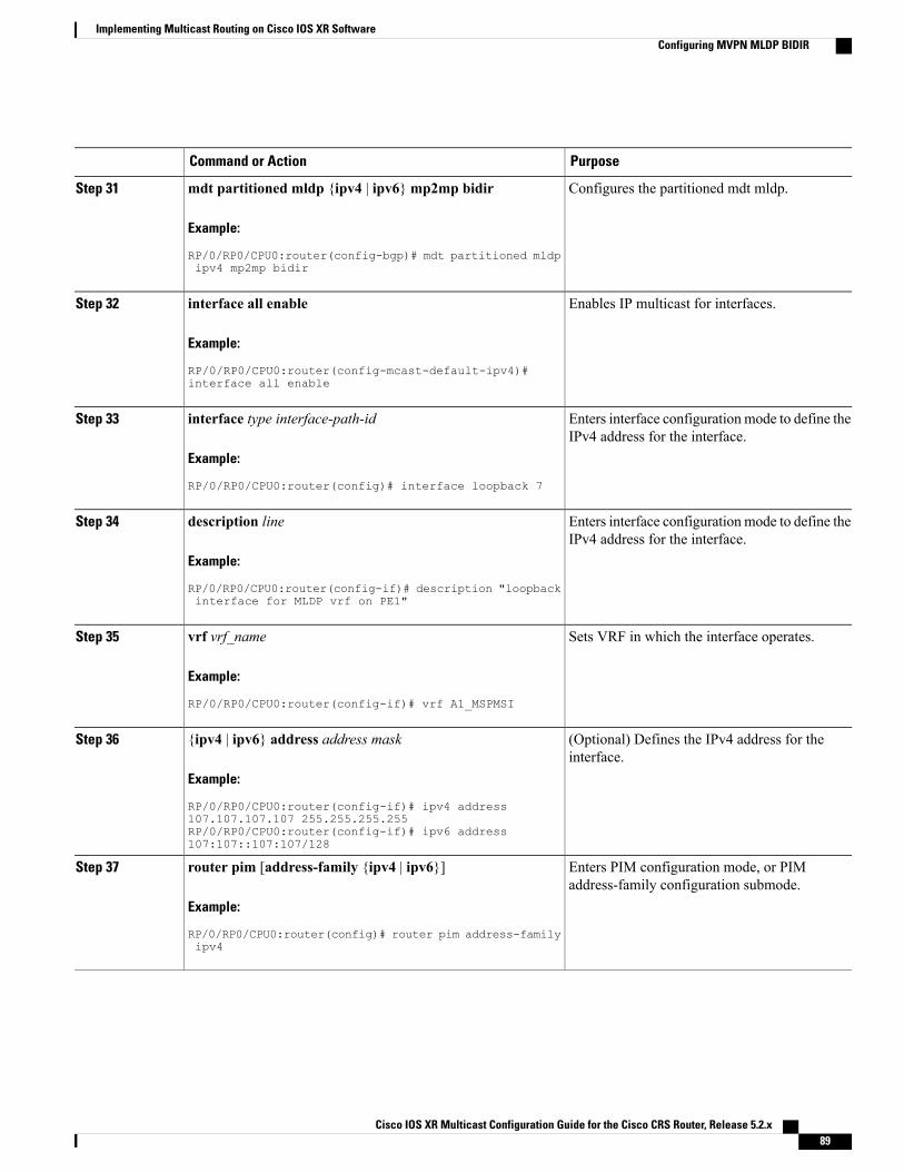
PurposeCommand or Action
Configures the partitioned mdt mldp.mdt partitioned mldp {ipv4 | ipv6}mp2mp bidir
Example:
RP/0/RP0/CPU0:router(config-bgp)# mdt partitioned mldp
Step 31
ipv4 mp2mp bidir
Enables IP multicast for interfaces.interface all enable
Example:
RP/0/RP0/CPU0:router(config-mcast-default-ipv4)#
Step 32
interface all enable
Enters interface configuration mode to define theIPv4 address for the interface.
interface type interface-path-id
Example:
RP/0/RP0/CPU0:router(config)# interface loopback 7
Step 33
Enters interface configuration mode to define theIPv4 address for the interface.
description line
Example:
RP/0/RP0/CPU0:router(config-if)# description "loopback
Step 34
interface for MLDP vrf on PE1"
Sets VRF in which the interface operates.vrf vrf_name
Example:
RP/0/RP0/CPU0:router(config-if)# vrf A1_MSPMSI
Step 35
(Optional) Defines the IPv4 address for theinterface.
{ipv4 | ipv6} address address mask
Example:
RP/0/RP0/CPU0:router(config-if)# ipv4 address
Step 36
107.107.107.107 255.255.255.255RP/0/RP0/CPU0:router(config-if)# ipv6 address107:107::107:107/128
Enters PIM configuration mode, or PIMaddress-family configuration submode.
router pim [address-family {ipv4 | ipv6}]
Example:
RP/0/RP0/CPU0:router(config)# router pim address-family
Step 37
ipv4
Cisco IOS XR Multicast Configuration Guide for the Cisco CRS Router, Release 5.2.x 89
Implementing Multicast Routing on Cisco IOS XR SoftwareConfiguring MVPN MLDP BIDIR

PurposeCommand or Action
Configures the Rendezvous point and assigns anRP to multicast groups.
rp-address ip-address
Example:
RP/0/RP0/CPU0:router(config-pim-default-ipv4)#
Step 38
The RP mechanism can be static,auto-rp, or BSR.
Note
rp-address 10.10.10.10
Sets VRF in which the interface operates.vrf vrf_name
Example:
RP/0/RP0/CPU0:router(config-pim)# vrf A1_MSPMSI
Step 39
Configures ipv4 address-family for mvpn andenters the address family command mode.
address-family {ipv4 | ipv6}
Example:
RP/0/RP0/CPU0:router(config-pim-A1_MSPMSI)#
Step 40
address-family ipv4
Assigns a given routing policy to an RPFtopology table.
rpf topology route-policy policy_name
Example:
RP/0/RP0/CPU0:router(config-pim-A1_MSPMSI-ipv4)# rpf
Step 41
topology route-policy partitioned-mldp-mp2mp
Assigns an RP to multicast groups.rp-address ip-address [group-access-list] [bidir]
Example:
RP/0/RP0/CPU0:router(config-pim-default-ipv4)#
Step 42
rp-address 107:107::107:107 group_2_v6 bidir
commitStep 43
Configuring a Static RP and Allowing Backward CompatibilityWhen PIM is configured in sparse mode, you must choose one or more routers to operate as a rendezvouspoint (RP) for a multicast group. An RP is a single common root placed at a chosen point of a shared distributiontree. An RP can either be configured statically in each router, or learned through Auto-RP or BSR.
This task configures a static RP. For more information about RPs, see the Rendezvous Points, on page 16.For configuration information for Auto-RP, see the Configuring Auto-RP to Automate Group-to-RPMappings,on page 92.
Cisco IOS XR Multicast Configuration Guide for the Cisco CRS Router, Release 5.2.x90
Implementing Multicast Routing on Cisco IOS XR SoftwareConfiguring a Static RP and Allowing Backward Compatibility

SUMMARY STEPS
1. configure2. router pim [address-family {ipv4 | ipv6}]3. rp-address ip-address [group-access-list] [] [override]4. old-register-checksum5. exit6. {ipv4 | ipv6} access-list name7. [sequence-number] permit source [source-wildcard]8. commit
DETAILED STEPS
PurposeCommand or Action
configureStep 1
Enters PIM configuration mode, or PIM address-familyconfiguration submode.
router pim [address-family {ipv4 | ipv6}]
Example:
RP/0/RP0/CPU0:router(config)# router pim
Step 2
Assigns an RP to multicast groups.rp-address ip-address [group-access-list] [] [override]Step 3
Example:
RP/0/RP0/CPU0:router(config-pim-default-ipv4)#
• If you specify a group-access-list-number value, youmust configure that access list using the ipv4 access-listcommand.
rp-address 172.16.6.22 rp-access
(Optional) Allows backward compatibility on the RP thatuses old register checksum methodology.
old-register-checksum
Example:
RP/0/RP0/CPU0:router(config-pim-ipv4)#
Step 4
old-register-checksum
Exits PIM configuration mode, and returns the router to thesource configuration mode.
exit
Example:
RP/0/RP0/CPU0:router(config-pim-ipv4)# exit
Step 5
(Optional) Enters access list configuration mode andconfigures the RP access list.
{ipv4 | ipv6} access-list name
Example:
RP/0/RP0/CPU0:router(config)# ipv4 access-list
Step 6
• The access list called “rp-access” permits multicast group239.1.1.0 0.0.255.255.
rp-access
Cisco IOS XR Multicast Configuration Guide for the Cisco CRS Router, Release 5.2.x 91
Implementing Multicast Routing on Cisco IOS XR SoftwareConfiguring a Static RP and Allowing Backward Compatibility

PurposeCommand or Action
(Optional) Permits multicast group 239.1.1.0 0.0.255.255 forthe “rp-access” list.
[sequence-number] permit source [source-wildcard]
Example:
RP/0/RP0/CPU0:router(config-ipv4-acl)# permit
Step 7
The commands in Step 6, on page 91 and Step 7, onpage 92 can be combined in one command string likethis: ipv4 access-list rp-access permit 239.1.1.00.0.255.255.
Tip
239.1.1.0 0.0.255.255
commitStep 8
Configuring Auto-RP to Automate Group-to-RP MappingsThis task configures the Auto-RP mechanism to automate the distribution of group-to-RP mappings in yournetwork. In a network running Auto-RP, at least one router must operate as an RP candidate and anotherrouter must operate as an RP mapping agent.
SUMMARY STEPS
1. configure2. router pim [address-family ipv4]3. auto-rp candidate-rp type instance scope ttl-value [group-list access-list-name] [interval seconds] bidir4. auto-rp mapping-agent type number scope ttl-value [interval seconds]5. exit6. ipv4 access-list name7. [sequence-number] permit source [source-wildcard]8. commit
DETAILED STEPS
PurposeCommand or Action
configureStep 1
Enters PIM configuration mode, or PIM address-family configurationsubmode.
router pim [address-family ipv4]
Example:
RP/0/RP0/CPU0:router(config)# router pim
Step 2
Configures an RP candidate that sends messages to theCISCO-RP-ANNOUNCE multicast group (224.0.1.39).
auto-rp candidate-rp type instance scopettl-value [group-list access-list-name] [intervalseconds] bidir
Step 3
• This example sends RP announcements out all PIM-enabledinterfaces for a maximum of 31 hops. The IP address by which
Cisco IOS XR Multicast Configuration Guide for the Cisco CRS Router, Release 5.2.x92
Implementing Multicast Routing on Cisco IOS XR SoftwareConfiguring Auto-RP to Automate Group-to-RP Mappings

PurposeCommand or Action
Example:
RP/0/RP0/CPU0:router(config-pim-ipv4)#
the router wants to be identified as an RP is the IP addressassociated with GigabitEthernet interface 0/1/0/1.
• Access list 2 designates the groups this router serves as RP.auto-rp candidate-rp • If you specify group-list, you must configure the optional
access-list command.GigabitEthernet0/1/0/1 scope 31group-list 2 bidir
Configures the router to be an RP mapping agent on a specifiedinterface.
auto-rp mapping-agent type number scopettl-value [interval seconds]
Step 4
Example:
RP/0/RP0/CPU0:router(config-pim-ipv4)#
• After the router is configured as an RP mapping agent anddetermines the RP-to-group mappings through theCISCO-RP-ANNOUNCE (224.0.1.39) group, the router sendsthe mappings in an Auto-RP discovery message to thewell-known group CISCO-RP-DISCOVERY (224.0.1.40).
auto-rp mapping-agentGigabitEthernet0/1/0/1 scope 20
• A PIM DR listens to this well-known group to determine whichRP to use.
• This example limits Auto-RP discovery messages to 20 hops.
Exits PIM configuration mode and returns the router to the sourceconfiguration mode.
exit
Example:
RP/0/RP0/CPU0:router(config-pim-ipv4)#
Step 5
exit
(Optional) Defines the RP access list.ipv4 access-list name
Example:
RP/0/RP0/CPU0:router(config)# ipv4
Step 6
access-list 2
(Optional) Permits multicast group 239.1.1.1 for the RP access list.[sequence-number] permit source[source-wildcard]
Step 7
The commands in Step 6, on page 93 and Step 7, on page93 can be combined in one command string and entered fromthe global or XR config mode like this: ipv4 access-listrp-access permit 239.1.1.1 0.0.0.0
Tip
Example:
RP/0/RP0/CPU0:router(config-ipv4-acl)#permit 239.1.1.1 0.0.0.0
commitStep 8
Cisco IOS XR Multicast Configuration Guide for the Cisco CRS Router, Release 5.2.x 93
Implementing Multicast Routing on Cisco IOS XR SoftwareConfiguring Auto-RP to Automate Group-to-RP Mappings

Configuring the Bootstrap RouterThis task configures one or more candidate bootstrap routers (BSRs) and a BSR mapping agent. This taskalso connects and locates the candidate BSRs in the backbone portion of the network.
For more information about BSR, see the PIM Bootstrap Router, on page 18.
SUMMARY STEPS
1. configure2. router pim [address-family {ipv4 | ipv6}]3. bsr candidate-bsr ip-address [hash-mask-len length] [priority value]4. bsr candidate-rp ip-address [group-list access-list interval seconds] [priority value] bidir5. interface type interface-path-id6. bsr-border7. exit8. exit9. {ipv4 | ipv6} access-list name10. Do one of the following:
• [sequence-number] permit source [source-wildcard]
• [sequence-number] permit source-prefix dest-prefix
11. commit12. clear pim [vrf vrf-name] [ipv4 | ipv6] bsr13. show pim [vrf vrf-name] [ipv4 | ipv6] bsr candidate-rp14. show pim [vrf vrf-name] [ipv4 | ipv6] bsr election15. show pim [vrf vrf-name][ipv4 | ipv6] bsr rp-cache16. show pim [vrf vrf-name][ipv4 | ipv6] group-map [ip-address-name] [info-source]
DETAILED STEPS
PurposeCommand or Action
configureStep 1
Enters PIM configuration mode, or address-familyconfiguration submode.
router pim [address-family {ipv4 | ipv6}]
Example:
RP/0/RP0/CPU0:router(config)# router pim
Step 2
Configures the router to announce its candidacy as a BSR.bsr candidate-bsr ip-address [hash-mask-len length][priority value]
Step 3
Cisco IOS XR Multicast Configuration Guide for the Cisco CRS Router, Release 5.2.x94
Implementing Multicast Routing on Cisco IOS XR SoftwareConfiguring the Bootstrap Router

PurposeCommand or Action
Example:
RP/0/RP0/CPU0:router(config-pim-default-ipv4)#bsr candidate-bsr 10.0.0.1 hash-mask-len 30
Configures the router to advertise itself as a PIM Version2 candidate RP to the BSR.
bsr candidate-rp ip-address [group-list access-listinterval seconds] [priority value] bidir
Step 4
Example:
RP/0/RP0/CPU0:router(config-pim-default-ipv4)#
• See Step 9, on page 95 for group list 4configuration.
bsr candidate-rp 172.16.0.0 group-list 4 bidir
(Optional) Enters interface configuration mode for thePIM protocol.
interface type interface-path-id
Example:
RP/0/RP0/CPU0:router(config-pim-default-ipv4)#
Step 5
interface GigE 0/1/0/0
(Optional) Stops the forwarding of bootstrap router (BSR)messages on a Protocol Independent Multicast (PIM)router interface.
bsr-border
Example:
RP/0/RP0/CPU0:router(config-pim-ipv4-if)#bsr-border
Step 6
(Optional) Exits PIM interface configuration mode, andreturns the router to PIM configuration mode.
exit
Example:
RP/0/RP0/CPU0:router(config-pim-ipv4-if)# exit
Step 7
Exits PIM configuration mode.exit
Example:
RP/0/RP0/CPU0:router(config-pim-default-ipv4)#
Step 8
exit
(Optional) Defines the candidate group list to the BSR.{ipv4 | ipv6} access-list nameStep 9
Example:
RP/0/RP0/CPU0:router(config)# ipv4 access-list 4
• Access list number 4 specifies the group prefixassociatedwith the candidate RP address 172.16.0.0.(See Step 4, on page 95).
• This RP is responsible for the groups with the prefix239.
Cisco IOS XR Multicast Configuration Guide for the Cisco CRS Router, Release 5.2.x 95
Implementing Multicast Routing on Cisco IOS XR SoftwareConfiguring the Bootstrap Router

PurposeCommand or Action
(Optional) Permits multicast group 239.1.1.1 for thecandidate group list.
Do one of the following:Step 10
• [sequence-number] permit source [source-wildcard]The commands in Step 6, on page 95 and Step 7,on page 95 can be combined in one commandstring and entered from global configuration modelike this: ipv4 access-list rp-access permit239.1.1.1 0.255.255.255
Tip• [sequence-number] permit source-prefix dest-prefix
Example:
RP/0/RP0/CPU0:router(config-ipv4-acl)# permit239.1.1.1 0.255.255.255
commitStep 11
(Optional) Clears BSR entries from the PIM RP groupmapping cache.
clear pim [vrf vrf-name] [ipv4 | ipv6] bsr
Example:
RP/0/RP0/CPU0:router# clear pim bsr
Step 12
(Optional) Displays PIM candidate RP information forthe BSR.
show pim [vrf vrf-name] [ipv4 | ipv6] bsr candidate-rp
Example:
RP/0/RP0/CPU0:router# show pim bsr candidate-rp
Step 13
(Optional) Displays PIM candidate election informationfor the BSR.
show pim [vrf vrf-name] [ipv4 | ipv6] bsr election
Example:
RP/0/RP0/CPU0:router# show pim bsr election
Step 14
(Optional) Displays PIM RP cache information for theBSR.
show pim [vrf vrf-name][ipv4 | ipv6] bsr rp-cache
Example:
RP/0/RP0/CPU0:router# show pim bsr rp-cache
Step 15
(Optional) Displays group-to-PIM mode mapping.show pim [vrf vrf-name][ipv4 | ipv6] group-map[ip-address-name] [info-source]
Step 16
Example:
RP/0/RP0/CPU0:router# show pim ipv4 group-map
Calculating Rates per RouteThis procedure enables multicast hardware forward-rate counters on a per-VRF-family basis.
Cisco IOS XR Multicast Configuration Guide for the Cisco CRS Router, Release 5.2.x96
Implementing Multicast Routing on Cisco IOS XR SoftwareCalculating Rates per Route

SUMMARY STEPS
1. configure2. multicast-routing [vrf vrf-name] [address-family {ipv4 | ipv6}]3. rate-per-route4. interface {type interface-path-id | all} enable5. Do one of the following:
• accounting per-prefix
• accounting per-prefix forward-only
6. commit7. show mfib [vrf vrf-name] [ipv4 | ipv6] route [rate | statistics] [* | source-address] [group-address
[/prefix-length] [detail | old-output] | summary] [location node-id]
DETAILED STEPS
PurposeCommand or Action
configureStep 1
Enters multicast routing configuration mode.multicast-routing [vrf vrf-name] [address-family {ipv4| ipv6}]
Step 2
• The following multicast processes are started: MRIB,MFWD, PIM, IGMP, and MLD.
Example:
RP/0/RP0/CPU0:router(config)# multicast-routing• For IPv4, IGMP version 3 is enabled by default; for IPv6,MLD version 1 is enabled by default.address-family ipv4
Enables a per (S,G) rate calculation for a particular route.rate-per-route
Example:
RP/0/RP0/CPU0:router(config-mcast-default-ipv4)#
Step 3
rate-per-route
Enables multicast routing on all interfaces.interface {type interface-path-id | all} enable
Example:
RP/0/RP0/CPU0:router(config-mcast-default-ipv4)#
Step 4
interface all enable
or
RP/0/RP0/CPU0:router(config-mcast-default-ipv4)#interface FastEthernet0/3/3/1 enable
Do one of the following:Step 5 • Enables per-prefix counters present in hardwareaccounting per-prefix—Enables three counters on ingress• accounting per-prefix (forward, punt and drop, and two on egress (forward and
Cisco IOS XR Multicast Configuration Guide for the Cisco CRS Router, Release 5.2.x 97
Implementing Multicast Routing on Cisco IOS XR SoftwareCalculating Rates per Route

PurposeCommand or Action
punt) on every existing and new (S, G) route. The (*, G)routes are assigned a single counter.
• accounting per-prefix forward-only
Example:
RP/0/RP0/CPU0:router(config-mcast-default-ipv)#
• accounting per-prefix forward-only—Enables one counteron ingress and one on egress in hardware to conservehardware statistics resources. (Recommended forconfiguration of multicast VPN routing or for any linecard that has a route-intensive configuration.)
accounting per-prefix
commitStep 6
Displays route entries in theMulticast Forwarding InformationBase (MFIB) table.
show mfib [vrf vrf-name] [ipv4 | ipv6] route [rate |statistics] [* | source-address] [group-address
Step 7
[/prefix-length] [detail | old-output] | summary] [locationnode-id] •When the rate keyword is used with the source- and
group-address, the command displays the cumulative
Example:
RP/0/RP0/CPU0:router# show mfib vrf 12 route
rates per route for all line cards in the MulticastForwarding Information Base (MFIB) table.
•When the statistics keyword is used, the commanddisplays the rate per route for one line card in theMulticast Forwarding Information Base (MFIB) table.
statistics location 0/1/cpU0
Configuring Multicast Nonstop ForwardingThis task configures the nonstop forwarding (NSF) feature for multicast packet forwarding for the purposeof alleviating network failures, or software upgrades and downgrades.
Although we strongly recommend that you use the NSF lifetime default values, the optional Step 3, on page99 through Step 6, on page 100 allow you tomodify the NSF timeout values for Protocol IndependentMulticast(PIM) and Internet Group Management Protocol (IGMP) or Multicast Listener Discovery (MLD). Use thesecommands when PIM and IGMP (or MLD) are configured with nondefault interval or query intervals for joinand prune operations.
Generally, configure the IGMP NSF and PIM NSF lifetime values to equal or exceed the query or join queryinterval. For example, if you set the IGMP query interval to 120 seconds, set the IGMP NSF lifetime to 120seconds (or greater).
If the Cisco IOS XR Software control plane does not converge and reconnect after NSF is enabled on yourrouter, multicast packet forwarding continues for up to 15 minutes, then packet forwarding stops.
Before You Begin
For NSF to operate in your multicast network, you must also enable NSF for the unicast protocols (such asIS-IS, OSPF, and BGP) that PIM relies on for Reverse Path Forwarding (RPF) information. See the appropriateconfiguration modules to learn how to configure NSF for unicast protocols.
Cisco IOS XR Multicast Configuration Guide for the Cisco CRS Router, Release 5.2.x98
Implementing Multicast Routing on Cisco IOS XR SoftwareConfiguring Multicast Nonstop Forwarding

SUMMARY STEPS
1. configure2. router pim [address-family {ipv4 | ipv6}]3. nsf lifetime seconds4. exit5. router {igmp | }6. nsf lifetime seconds7. commit8. show {igmp |mld} [ old-output] nsf9. show mfib [ipv4 | ipv6] nsf [location node-id]10. show mrib [ipv4 | ipv6] [old-output] nsf11. show pim [ipv4 | ipv6] nsf
DETAILED STEPS
PurposeCommand or Action
configureStep 1
(Optional) Enters PIM address-family configurationsubmode.
router pim [address-family {ipv4 | ipv6}]
Example:
RP/0/RP0/CPU0:router(config)# router pim
Step 2
address-family ipv4
(Optional) Configures the NSF timeout value for multicastforwarding route entries under the PIM process.
nsf lifetime seconds
Example:
RP/0/RP0/CPU0:router(config-pim-default-ipv4)#
Step 3
If you configure the PIM hello interval to anondefault value, configure the PIM NSF lifetimeto a value less than the hello hold time. Typicallythe value of the hold-time field is 3.5 times theinterval time value, or 120 seconds if the PIM hellointerval time is 30 seconds.
Note
nsf lifetime 30
(Optional) Exits PIM configuration mode and returns therouter to the source configuration mode.
exit
Example:
RP/0/RP0/CPU0:router(config-pim-default-ipv4)#
Step 4
exit
(Optional) Enters router IGMP configuration mode.router {igmp | }
Example:
RP/0/RP0/CPU0:router(config)# router igmp
Step 5
Cisco IOS XR Multicast Configuration Guide for the Cisco CRS Router, Release 5.2.x 99
Implementing Multicast Routing on Cisco IOS XR SoftwareConfiguring Multicast Nonstop Forwarding

PurposeCommand or Action
(Optional) Configures the NSF timeout value for multicastforwarding route entries under the IGMP or MLD process.
nsf lifetime seconds
Example:
RP/0/RP0/CPU0:router(config-igmp)# nsf lifetime
Step 6
30
commitStep 7
(Optional) Displays the state of NSF operation in IGMP orMLD.
show {igmp |mld} [ old-output] nsf
Example:
RP/0/RP0/CPU0:router# show igmp nsf
Step 8
(Optional) Displays the state of NSF operation for theMFIBline cards.
show mfib [ipv4 | ipv6] nsf [location node-id]
Example:
RP/0/RP0/CPU0:router# show mfib nsf
Step 9
(Optional) Displays the state of NSF operation in theMRIB.show mrib [ipv4 | ipv6] [old-output] nsf
Example:
RP/0/RP0/CPU0:router# show mrib nsf
Step 10
(Optional) Displays the state of NSF operation for PIM.show pim [ipv4 | ipv6] nsf
Example:
RP/0/RP0/CPU0:router# show pim nsf
Step 11
Configuring Multicast VPN• Enabling a VPN for Multicast Routing, on page 101 (required)
• “Configuring BGP to Advertise VRF Routes for Multicast VPN from PE to PE” (required)See themodule “Implementing BGP on Cisco IOSXRSoftware in Cisco IOS XRRouting ConfigurationGuide for the Cisco CRS Router.
• Configuring an MDT Address Family Session in BGP as a PE-to- PE Protocol (optional for PIM-SMMDT groups; required for PIM-SSM MDT groups)
See the “Configuring an MDT Address Family Session in BGP” section in Cisco IOS XR RoutingConfiguration Guide for the Cisco CRS Router.
• Configuring a provider-edge-to-customer-edge protocol (optional)
Cisco IOS XR Multicast Configuration Guide for the Cisco CRS Router, Release 5.2.x100
Implementing Multicast Routing on Cisco IOS XR SoftwareConfiguring Multicast VPN

See the “Configuring BGP as a PE-CE Protocol,” “Configuring OSPF as a PE-to-CE Protocol,” and“Configuring EIGRP as a PE-to CE Protocol” sections in Cisco IOS XR Routing Configuration Guidefor the Cisco CRS Router.
• Specifying the PIM VRF Instance, on page 104 (optional)
Prerequisites for Multicast VPN• PIM andmulticast forwardingmust be configured on all interfaces used bymulticast traffic. In anMVPN,you must enable PIM and multicast forwarding for the following interfaces:
◦Physical interface on a provider edge (PE) router that is connected to the backbone.
◦Interface used for BGP peering source address.
◦Any interfaces configured as PIM rendezvous points.
PIM and multicast forwarding are enabled in multicast routing configuration mode. Noadditional configuration is required in router pim mode to enable the PIM protocol.
Note
• Interfaces in the VPN intended for use in forwarding multicast traffic must be enabled for PIM andmulticast forwarding.
• BGP should already be configured and operational on all routers that are sending or receiving multicasttraffic.
• To enable MVPN, you must include a VPN IPv4 address-family (AFI) in your BGP configuration. SeeRestrictions forMulticast VPN forMulticast Routing, on page 101. (See also the “Enabling BGPRouting”section in Cisco IOS XR Routing Configuration Guide.)
• All PE routers in the multicast domain must be running a Cisco IOS XR Software image that supportsMVPN.
• Multicast forwarding must be configured for the global IPv4 address family.
• Each multicast SM VRF domain must have an associated PIM rendezvous point (RP) definition. UsingAuto-RP and the bootstrap router (BSR), you may configure RP services in the MVPN on thecustomer-edge (CE) device because the MVPN learns about the RP dynamically. The VRF interfacecan be used as a listener on the PE device.
To enable static RP services, you must configure every device in the domain for this purpose.
Restrictions for Multicast VPN for Multicast Routing• Configuration of the MDT source on a per-VRF basis is only supported on IPv4.
• The MDT group address should be the same for both the address families in the same VRF.
Enabling a VPN for Multicast RoutingThis task enables multicast VPN routing for IPv4.
Cisco IOS XR Multicast Configuration Guide for the Cisco CRS Router, Release 5.2.x 101
Implementing Multicast Routing on Cisco IOS XR SoftwareConfiguring Multicast VPN

The MDT group address is used by provider edge (PE) routers to form a virtual PIM “neighborship” for theMDT. This enables the PEs to communicate with other PEs in the VRF as if they shared a LAN.
When sending customer VRF traffic, PEs encapsulate the traffic in their own (S,G) state, where the G is theMDT group address, and the S is the MDT source for the PE. By joining the (S,G) MDT of its PE neighbors,a PE router is able to receive the encapsulated multicast traffic for that VRF.
Although the VRF itself may have many multicast sources sending to many groups, the provider networkneeds only to install state for one group per VRF, in other words, the MDT group.
SUMMARY STEPS
1. configure2. multicast-routing3. address-family ipv44. nsf5. mdt source type interface-path-id6. interface all enable7. vrf vrf-name8. address-family {ipv4}]9. mdt default mdt-group-address10. mdt data mdt-group-address/prefix-length threshold threshold acl-name11. mdt mtu size12. interface all enable13. commit
DETAILED STEPS
PurposeCommand or Action
configureStep 1
Enters multicast routing configuration mode.multicast-routing
Example:
RP/0/RP0/CPU0:router(config)# multicast-routing
Step 2
Enters ipv4 address-family submode.address-family ipv4
Example:
RP/0/RP0/CPU0:router(config-mcast)#
Step 3
address-family ipv4
Specifies that nonstop forwarding (NSF) maintains theforwarding state in case of a disruption to a multicast process.
nsf
Example:
RP/0/RP0/CPU0:router(config-mcast-default-ipv4)#
Step 4
Cisco IOS XR Multicast Configuration Guide for the Cisco CRS Router, Release 5.2.x102
Implementing Multicast Routing on Cisco IOS XR SoftwareConfiguring Multicast VPN

PurposeCommand or Action
nsf
Specifies the MDT source address.mdt source type interface-path-idStep 5
Example:
RP/0/RP0/CPU0:router(config-mcast-default-ipv4)#
TheMDT source interface name should be the sameas the one used for BGP.
Note
mdt source GigE 0/1/0/0
Enables multicast routing and forwarding on all new andexisting interfaces. You can also enable individual interfaces.
interface all enable
Example:
RP/0/RP0/CPU0:router(config-mcast-default-ipv4)#
Step 6
To avoid any possibility of a reverse-pathforwarding (RPF) failure, you should proactivelyenable any interfaces that might possibly carrymulticast traffic.
Caution
interface all enable
Configures a VPN routing and forwarding (VRF) instanceand enters VRF configuration mode.
vrf vrf-name
Example:
RP/0/RP0/CPU0:router(config-mcast-default-)# vrf
Step 7
vrf_A
Specifies the virtual routing and forwarding instance for theipv4 address family.
address-family {ipv4}]Step 8
Specifies the multicast distribution tree (MDT) default groupaddress.
mdt default mdt-group-address
Example:
RP/0/RP0/CPU0:router(config-mcast-vrf_A-ipv4)#
Step 9
mdt default 239.23.2.1
(IPv4 MVPN configuration only) Specifies the multicastgroup address range to be used for data MDT traffic.
mdt data mdt-group-address/prefix-length thresholdthreshold acl-name
Step 10
Example:
RP/0/RP0/CPU0:router(config-mcast-vrf_A-ipv4)#
This group range should not overlap the MDTdefault group.
Note
This is an optional command. The default threshold beyondwhich traffic is sent using a data MDT group is 1 kbps.However, you may configure a higher threshold, if desired.
mdt data 239.23.3.0/24 threshold 1200 acl-A
You may also, optionally, configure an access list to limitthe number of groups to be tunneled through a data MDTgroup. Traffic from groups not on the access-list continuesto be tunneled using the default MDT group.
This is an optional step.mdt mtu sizeStep 11
Example:
RP/0/RP0/CPU0:router(config-mcast-default-ipv4)#
Specifies the MTU size. It is recommended to configure ahigh value, to accommodate the maximum multicast packetsize.
Cisco IOS XR Multicast Configuration Guide for the Cisco CRS Router, Release 5.2.x 103
Implementing Multicast Routing on Cisco IOS XR SoftwareConfiguring Multicast VPN

PurposeCommand or Action
The default MTU for PIM/GRE MDT is 1376 andthe default value for mLDP/P2MP-TEMDT is 9000for Multicast VPN.
Notemdt mtu 1550
Enables multicast routing and forwarding on all new andexisting interfaces.
interface all enable
Example:
RP/0/RP0/CPU0:router(config-mcast-default-ipv4)#
Step 12
interface all enable
commitStep 13
Specifying the PIM VRF InstanceIf you are configuring Protocol Independent Multicast in sparse mode (PIM-SM) in the MVPN, you may alsoneed to configure a rendezvous point (RP). This task specifies the optional PIM VPN instance.
SUMMARY STEPS
1. configure2. router pim vrf vrf-name address-family {ipv4 | ipv6}3. rp-address ip-address [group-access-list-name] [bidir] [override]4. commit
DETAILED STEPS
PurposeCommand or Action
configureStep 1
Enters PIM address-family configuration submode andconfigures the PIM VRF for either an IPv4 or IPv6 addressfamily.
router pim vrf vrf-name address-family {ipv4 |ipv6}
Example:
RP/0/RP0/CPU0:router(config)# router pim vrf
Step 2
vrf_A address-family ipv4
Configures the PIM rendezvous point (RP) address:rp-address ip-address [group-access-list-name][bidir] [override]
Step 3
• group-access-list-name = Specifies an access list ofgroups to be mapped to a given RP.
Example:
RP/0/RP0/CPU0:router(config-pim-vrf_A-ipv4)#• bidir = Specifies a bidirectional RP.
rp-address 10.0.0.0 • override = Specifies that a static RP configuration shouldoverride auto-RP and the bootstrap router (BSR).
Cisco IOS XR Multicast Configuration Guide for the Cisco CRS Router, Release 5.2.x104
Implementing Multicast Routing on Cisco IOS XR SoftwareConfiguring Multicast VPN

PurposeCommand or Action
commitStep 4
Specifying the IGMP VRF Instance
SUMMARY STEPS
1. configure2. router igmp3. vrf vrf-name4. commit
DETAILED STEPS
PurposeCommand or Action
configureStep 1
Enters IGMP configuration mode.router igmp
Example:
RP/0/RP0/CPU0:router(config)# router igmp
Step 2
Configures a VRF instance.vrf vrf-name
Example:
RP/0/RP0/CPU0:router(config-igmp)# vrf vrf_B
Step 3
commitStep 4
Configuring the MDT Source per VRFThis optional feature lets you change the default routing mechanism in a multicast VPN network topology,which routes all unicast traffic through a BGP peering loopback configured on a default VRF. Instead, youmay configure a loopback that allows you to specify the MDT source using a specific VRF, as opposed to thedefault VRF. This overrides the current behavior and updates BGP as part of aMDT group. BGP then modifiesthe source and connector attributes in the MDT SAFI and VPN IPv4 updates.
For VRFs on which the MDT source is not configured, the MDT source for the default VRF is applied. Also,when the MDT source on a VRF is unconfigured, the configuration of the MDT source default VRF takeseffect.
Cisco IOS XR Multicast Configuration Guide for the Cisco CRS Router, Release 5.2.x 105
Implementing Multicast Routing on Cisco IOS XR SoftwareConfiguring Multicast VPN

In the configuration below, the default VRF does not require explicit reference in Step 5.Note
SUMMARY STEPS
1. configure2. multicast-routing3. address-family [ ipv4 | ipv6 ]4. mdt source loopback 05. exit6. vrf 1017. address-family ipv48. mdt source loopback 19. Repeat the steps 6 to 8, as many times as needed to create other VRFs.10. commit11. show pim vrf all mdt interface
DETAILED STEPS
PurposeCommand or Action
configureStep 1
Enables IP multicast routing and forwarding.multicast-routing
Example:
RP/0/RP0/CPU0:router(config)# multicast-routing
Step 2
RP/0/RP0/CPU0:router(config-mcast)#
Enters ipv4 (or ipv6) address-family submode.address-family [ ipv4 | ipv6 ]
Example:
RP/0/RP0/CPU0:router(config-mcast)# address-family ipv4
Step 3
Configures the interface used to set the MDTsource address for MVPN, using the defaultVRF.
mdt source loopback 0
Example:
RP/0/RP0/CPU0:router(config-mcast-default-ipv4)# mdt
Step 4
source loopback 0
Cisco IOS XR Multicast Configuration Guide for the Cisco CRS Router, Release 5.2.x106
Implementing Multicast Routing on Cisco IOS XR SoftwareConfiguring Multicast VPN

PurposeCommand or Action
Exits from the current mode.exit
Example:
RP/0/RP0/CPU0:router(config-mcast-default-ipv4)# exit
Step 5
vrf 101Step 6
Example:
RP/0/RP0/CPU0:router(config-mcast)# vrf 101
Enters the IPv4 address-family mode.address-family ipv4
Example:
RP/0/RP0/CPU0:router(config-mcast-101)# address-family
Step 7
ipv4
Configures the interface used to set the MDTsource address for MVPN.
mdt source loopback 1
Example:
RP/0/RP0/CPU0:router(config-mcast-101-ipv4)# mdt source
Step 8
loopback 1
—Repeat the steps 6 to 8, as many times as needed to create otherVRFs.
Step 9
Example:
RP/0/RP0/CPU0:router(config-mcast)# vrf 102 mdt sourceloopback 2
commitStep 10
To verify the MDT source per VRFconfiguration, use the show pim vrf all mdtinterface command.
show pim vrf all mdt interface
Example:
RP/0/RP0/CPU0:router# show pim vrf all mdt interface
Step 11
GroupAddress Interface Source Vrf
239.0.0.239 mdtVRF_NAME Loopback1VRF_NAME
Cisco IOS XR Multicast Configuration Guide for the Cisco CRS Router, Release 5.2.x 107
Implementing Multicast Routing on Cisco IOS XR SoftwareConfiguring Multicast VPN

Configuring Label Switched MulticastDeployment of an LSM MLDP-based MVPN involves configuring a default MDT and one or more dataMDTs. A static default MDT is established for each multicast domain. The default MDT defines the pathused by PE routers to send multicast data and control messages to other PE routers in the multicast domain.A default MDT is created in the core network using a single MP2MP LSP.
An LSP MLDP-based MVPN also supports dynamic creation of the data MDTs for high-bandwidthtransmission. For high-rate data sources, a data MDT is created using the P2MP LSPs to off-load the trafficfrom the default MDT to avoid unnecessary waste of bandwidth to PEs that are not part of the stream. Youcan configure MLDP MVPN for both the intranet or extranet. This configuration section covers the rosenbasedMLDP profile. For configuration examples of otherMLDP profiles, see Configuring LSM basedMLDP:Examples, on page 180.
Before configuring MLDP based MVPN, ensure that the MPLS is enabled on the core facing interface.For information in MPLS configuration, see Cisco IOS XRMPLS Configuration Guide. Also, ensure thatBGP and any interior gateway protocol (OSPF or ISIS) is enabled on the core router. For more informationon BGP and route-policy configuration, see Cisco IOS XR Routing Configuration Guide.
Note
Perform this task to configure label switched multicast:
Cisco IOS XR Multicast Configuration Guide for the Cisco CRS Router, Release 5.2.x108
Implementing Multicast Routing on Cisco IOS XR SoftwareConfiguring Multicast VPN

SUMMARY STEPS
1. configure2. mpls ldp mldp3. root4. vrf vrf_name5. vpn id vpn-id6. address-family [ipv4 | ipv6 ] unicast7. import route-target [xx.yy.nn | as-number:nn | ip-address:nn ]8. export route-target [xx.yy.nn | as-number:nn | ip-address:nn ]9. root10. multicast-routing vrf vrf_name11. address-family [ipv4 | ipv6 ]12. mdt default mldp ipv4 root-node13. mdt data mdt-group-address threshold value14. root15. router bgp as-number vrf vrf-name16. rd route-distinguisher17. address-family ipv4 mdt18. address-family vpnv4 unicast19. root20. router pim21. vrf vrf_name22. address-family [ipv4 | ipv6 ]23. rpf topology route-policy route_policy_name24. root25. route-policy route_policy_name26. set core-tree tree_type27. commit
DETAILED STEPS
PurposeCommand or Action
configureStep 1
Enables MPLS MLDP support.mpls ldp mldp
Example:
RP/0/RP0/CPU0:router(config)# mpls ldp mldp
Step 2
Cisco IOS XR Multicast Configuration Guide for the Cisco CRS Router, Release 5.2.x 109
Implementing Multicast Routing on Cisco IOS XR SoftwareConfiguring Multicast VPN

PurposeCommand or Action
Takes the user to the global configuration level.root
Example:
RP/0/RP0/CPU0:router(config-ldp-mldp)# root
Step 3
Configures a VRF instance. The vrf-name argument is thename assigned to a VRF.
vrf vrf_name
Example:
RP/0/RP0/CPU0:router(config)# vrf vrf1
Step 4
Sets or updates a VPN identifier on a VRF.vpn id vpn-id
Example:
RP/0/RP0/CPU0:router(config-vrf)# vpn id 1:1
Step 5
Enters the address-family submode.address-family [ipv4 | ipv6 ] unicast
Example:
RP/0/RP0/CPU0:router(config-vrf)#
Step 6
address-family ipv4 unicast
Imports the selected route target, optionally expressed as oneof the following:
import route-target [xx.yy.nn | as-number:nn |ip-address:nn ]
Example:
RP/0/RP0/CPU0:router(config-vrf-af)# import
Step 7
• 4-byte AS number of the route target in xx.yy:nn format.Range is 0-65535.0-65535:0-65535
• AS number of the route target in nn format. Range is0-65535.
route-target import 1:1
• IP address of the route target in A.B.C.D. format.
Exports the selected route target, optionally expressed as oneof the following:
export route-target [xx.yy.nn | as-number:nn |ip-address:nn ]
Example:
RP/0/RP0/CPU0:router(config-vrf-af)# export
Step 8
• 4-byte AS number of the route target in xx.yy:nn format.Range is 0-65535.0-65535:0-65535
• AS number of the route target in nn format. Range is0-65535.
route-target export 1:1
• IP address of the route target in A.B.C.D. format.
Cisco IOS XR Multicast Configuration Guide for the Cisco CRS Router, Release 5.2.x110
Implementing Multicast Routing on Cisco IOS XR SoftwareConfiguring Multicast VPN

PurposeCommand or Action
Takes the user to the global configuration level.root
Example:
RP/0/RP0/CPU0:router(config-vrf-af)# root
Step 9
Enables multicast routing for the specified VRF.multicast-routing vrf vrf_name
Example:
RP/0/RP0/CPU0:router(config)#
Step 10
multicast-routing vrf vrf1
Enters the address-family submode.address-family [ipv4 | ipv6 ]
Example:
RP/0/RP0/CPU0:router(config-mcast-vrf1)#
Step 11
address-family ipv4
Configures MLDPMDT for a VRF. The root node can be IPaddress of a loopback or physical interface on any router
mdt default mldp ipv4 root-node
Example:
RP/0/RP0/CPU0:router(config-mcast-vrf1-ipv4)#
Step 12
(source PE, receiver PE or core router) in the providernetwork. The root node address should be reachable by allthe routers in the network. The router from where thesignalling occurs functions as the root node.
mdt default mldp ipv4 2.2.2.2
The default MDT must be configured on each PE router toenable the PE routers to receive multicast traffic for thisparticular MVRF.
By default MPLSMLDP is enabled. To disable, usethe no mpls ldp mldp command.
Note
LSPVIF tunnel is created as a result ofmdt defaultmldp root-node command.
Note
Configures the threshold value for data MDT.mdt data mdt-group-address threshold value
Example:
RP/0/RP0/CPU0:router(config-mcast-vrf1-ipv4)#
Step 13
mdt data 239.0.0.0/24 threshold 1000
Takes the user to the global configuration mode.root
Example:
RP/0/RP0/CPU0:router(config-mcast-vrf1-ipv4)#
Step 14
root
Cisco IOS XR Multicast Configuration Guide for the Cisco CRS Router, Release 5.2.x 111
Implementing Multicast Routing on Cisco IOS XR SoftwareConfiguring Multicast VPN

PurposeCommand or Action
Enters the BGP configuration mode.router bgp as-number vrf vrf-name
Example:
RP/0/RP0/CPU0:router(config)# router bgp 1
Step 15
vrf vrf1
Creates routing and forwarding tables. Specify theroute-distinguisher argument to add an 8-byte value to an
rd route-distinguisher
Example:
RP/0/RP0/CPU0:router(config-bgp-vrf)# rd
Step 16
IPv4 prefix to create a VPN IPv4 prefix. You can enter anRD value in either of these formats:
• 16-bit autonomous system number. For example, 101:3.1.1.1.1:1
• 32-bit IP address: your 16-bit number. For example,192.168.122.15:1.
Configures the BGP MDT address family.address-family ipv4 mdt
Example:
RP/0/RP0/CPU0:router(config-bgp-vrf)#
Step 17
address-family ipv4 mdt
Configures the BGP vpnv4 address family.address-family vpnv4 unicast
Example:
RP/0/RP0/CPU0:router(config-bgp-af)#
Step 18
address-family vpnv4 unicast
Takes the user to the global configuration mode.root
Example:
RP/0/RP0/CPU0:router(config-bgp-af)# root
Step 19
Enters the PIM configuration mode.router pim
Example:
RP/0/RP0/CPU0:router(config)# router pim
Step 20
Specifies the VRF instance. .vrf vrf_name
Example:
RP/0/RP0/CPU0:router(config-pim)# vrf vrf1
Step 21
Cisco IOS XR Multicast Configuration Guide for the Cisco CRS Router, Release 5.2.x112
Implementing Multicast Routing on Cisco IOS XR SoftwareConfiguring Multicast VPN

PurposeCommand or Action
Enters the address-family submode.address-family [ipv4 | ipv6 ]
Example:
RP/0/RP0/CPU0:router(config-pim-vrf1)#
Step 22
address-family ipv4
Assigns a given routing policy to an RPF topology table.rpf topology route-policy route_policy_name
Example:
RP/0/RP0/CPU0:router(config-pim-vrf1-af)# rpf
Step 23
topology route-policy FOO
Takes the user to the global configuration mode.root
Example:
RP/0/RP0/CPU0:router(config-pim-vrf1-af)# root
Step 24
Configures the route policy for a profile. For moreinformation about configuring route policy, see Cisco IOSXR Routing Configuration Guide.
route-policy route_policy_name
Example:
RP/0/RP0/CPU0:router(config)# route-policy
Step 25
FOO
Specifies the MDT type for the route policy.set core-tree tree_type
Example:
RP/0/RP0/CPU0:router(config-rpl)# set
Step 26
core-tree mldp-rosen
commitStep 27
Verification of LSM mLDP based MVPN ConfigurationUse these commands to verify the LSM mLDP based MVPN intranet configuration:
• To check the MLDP neighbors, use the show mpls mldp neighbors command:
Router# show mpls mldp neighborsmLDP neighbor databaseMLDP peer ID : 1.0.0.1:0, uptime 15:36:30 Up,Capabilities : GR, Typed Wildcard FEC, P2MP, MP2MP, MBBTarget Adj : NoUpstream count : 0Branch count : 0LDP GR : Enabled
Cisco IOS XR Multicast Configuration Guide for the Cisco CRS Router, Release 5.2.x 113
Implementing Multicast Routing on Cisco IOS XR SoftwareConfiguring Multicast VPN

: Instance: 1Label map timer : neverPolicy filter in : NonePath count : 1Path(s) : 11.11.11.10 GigabitEthernet0/2/0/0 LDPAdj list : 11.11.11.10 GigabitEthernet0/2/0/0Peer addr list : 8.39.21.2
: 1.0.0.1: 1.1.1.1: 1.2.2.1: 1.3.3.1: 1.4.4.1: 1.5.5.1: 1.6.6.1: 1.7.7.1: 1.8.8.1: 1.9.9.1: 1.10.10.1: 1.11.11.1: 1.12.12.1: 1.13.13.1: 1.14.14.1: 1.15.15.1: 1.16.16.1: 1.17.17.1: 1.18.18.1: 1.19.19.1: 1.20.20.1: 1.21.21.1: 1.22.22.1: 1.23.23.1: 1.24.24.1: 1.25.25.1: 1.26.26.1: 1.27.27.1: 1.28.28.1: 1.29.29.1: 1.30.30.1: 11.11.11.10: 111.113.1.5: 111.112.1.1: 8.39.21.222
MLDP peer ID : 3.0.0.1:0, uptime 15:36:31 Up,Capabilities : GR, Typed Wildcard FEC, P2MP, MP2MP, MBBTarget Adj : NoUpstream count : 334Branch count : 328LDP GR : Enabled
: Instance: 1Label map timer : neverPolicy filter in : NonePath count : 1Path(s) : 11.113.1.2 GigabitEthernet0/2/0/3 LDPAdj list : 11.113.1.2 GigabitEthernet0/2/0/3Peer addr list : 8.39.15.2
: 3.0.0.1: 189.189.189.189: 13.13.13.18: 11.113.1.2: 22.113.1.2: 111.113.1.6: 112.113.1.6
• To check the PIM neighbors, use the show pim vrf vrf-name neighbor command:
Router# show pim vrf A1_MIPMSI neighborPIM neighbors in VRF A1_MIPMSI
Neighbor Address Interface Uptime Expires DR pri s
101.2.2.101* Loopback2 15:54:43 00:00:02 1 (DR) BP
Cisco IOS XR Multicast Configuration Guide for the Cisco CRS Router, Release 5.2.x114
Implementing Multicast Routing on Cisco IOS XR SoftwareConfiguring Multicast VPN

101.0.0.101* LmdtA1/MIPMSI 15:54:43 00:00:02 1 B102.0.0.102 LmdtA1/MIPMSI 03:52:08 00:00:02 1 B103.0.0.103 LmdtA1/MIPMSI 15:28:13 00:00:02 1 (DR) B60.3.0.1 Multilink0/2/1/0/3 15:54:39 00:01:21 1 B60.3.0.2* Multilink0/2/1/0/3 15:54:43 00:00:02 1 (DR) BP60.1.0.5 Serial0/2/2/0/1:1.16 15:54:42 00:01:42 1 B60.1.0.6* Serial0/2/2/0/1:1.16 15:54:43 00:00:02 1 (DR) BP60.2.0.1 Serial0/5/0/0/1 15:54:42 00:01:17 1 B60.2.0.2* Serial0/5/0/0/1 15:54:43 00:00:02 1 (DR) BP
• To check the multicast routes for a given VRF, use show mrib vrf vrf_name route command:
Router# show mrib vrf A1_MIPMSI routeIP Multicast Routing Information BaseEntry flags: L - Domain-Local Source, E - External Source to the Domain,
C - Directly-Connected Check, S - Signal, IA - Inherit Accept,IF - Inherit From, D - Drop, MA - MDT Address, ME - MDT Encap,MD - MDT Decap, MT - MDT Threshold Crossed, MH - MDT interface handleCD - Conditional Decap, MPLS - MPLS Decap, MF - MPLS Encap, EX - ExtranetMoFE - MoFRR Enabled, MoFS - MoFRR State
Interface flags: F - Forward, A - Accept, IC - Internal Copy,NS - Negate Signal, DP - Don't Preserve, SP - Signal Present,II - Internal Interest, ID - Internal Disinterest, LI - Local Interest,LD - Local Disinterest, DI - Decapsulation InterfaceEI - Encapsulation Interface, MI - MDT Interface, LVIF - MPLS Encap,EX - Extranet, A2 - Secondary Accept
(*,224.0.0.0/24) Flags: DUp: 15:57:19
(*,224.0.1.39) Flags: SUp: 15:57:19
(*,224.0.1.40) Flags: SUp: 15:57:19
Outgoing Interface ListSerial0/5/0/0/1 Flags: II LI, Up: 15:57:12
(*,225.0.0.0/19) RPF nbr: 101.2.2.101 Flags: L CUp: 15:57:19
Outgoing Interface ListDecapstunnel98 Flags: NS DI, Up: 15:57:10
(*,225.0.32.0/19) RPF nbr: 102.0.0.102 Flags: CUp: 15:57:19
(*,225.0.32.1) RPF nbr: 102.0.0.102 Flags: CUp: 04:08:30
Incoming Interface ListLmdtA1/MIPMSI Flags: A LMI, Up: 04:08:30
Outgoing Interface ListSerial0/2/2/0/1:1.16 Flags: F NS, Up: 04:08:30
(*,225.0.32.2) RPF nbr: 102.0.0.102 Flags: CUp: 04:08:30
Incoming Interface ListLmdtA1/MIPMSI Flags: A LMI, Up: 04:08:30
Outgoing Interface ListSerial0/2/2/0/1:1.16 Flags: F NS, Up: 04:08:30
(*,225.0.32.3) RPF nbr: 102.0.0.102 Flags: CUp: 04:08:30
Incoming Interface ListLmdtA1/MIPMSI Flags: A LMI, Up: 04:08:30
Cisco IOS XR Multicast Configuration Guide for the Cisco CRS Router, Release 5.2.x 115
Implementing Multicast Routing on Cisco IOS XR SoftwareConfiguring Multicast VPN

Outgoing Interface ListSerial0/2/2/0/1:1.16 Flags: F NS, Up: 04:08:30
(*,225.0.32.4) RPF nbr: 102.0.0.102 Flags: CUp: 04:08:30
Incoming Interface ListLmdtA1/MIPMSI Flags: A LMI, Up: 04:08:30
Outgoing Interface ListSerial0/2/2/0/1:1.16 Flags: F NS, Up: 04:08:30
• To check the MPLS forwarding status, use show mpls forwarding command:
Router# show mpls forwardingLocal Outgoing Prefix Outgoing Next Hop BytesLabel Label or ID Interface Switched------ ----------- ------------------ ------------ --------------- ------------16000 16255 MLDP LSM ID: 0x1 Gi0/2/0/3 11.113.1.2 34872724016001 16254 MLDP LSM ID: 0x3 Gi0/2/0/3 11.113.1.2 34872723416002 16253 MLDP LSM ID: 0x5 Gi0/2/0/3 11.113.1.2 34872723416003 16252 MLDP LSM ID: 0x7 Gi0/2/0/3 11.113.1.2 34872723416004 16251 MLDP LSM ID: 0x9 Gi0/2/0/3 11.113.1.2 42187688216005 16250 MLDP LSM ID: 0xb Gi0/2/0/3 11.113.1.2 348726916
Configuring Multitopology RoutingThis set of procedures configures multitopology routing, which is used by PIM for reverse-path forwarding(RPF) path selection.
• “Configuring a Global Topology and Associating It with an Interface” (required)For information, see Cisco IOS XR Routing Configuration Guide for the Cisco CRS Router.
• “Enabling an IS-IS Topology” (required)For information, see Cisco IOS XR Routing Configuration Guide for the Cisco CRS Router.
• “Placing an Interface in a Topology in IS-IS” (required)For information, see Cisco IOS XR Routing Configuration Guide for the Cisco CRS Router.
• “Configuring a Routing Policy” (required)For information, see Cisco IOS XR Routing Configuration Guide for the Cisco CRS Router.
For an example of multitopology routing, see Configuring Multitopology Routing: Example, on page 159.
Restrictions for Configuring Multitopology Routing• Only the default VRF is currently supported in a multitopology solution.
• Only protocol-independent multicast (PIM) and intermediate system-intermediate system (IS-IS) routingprotocols are currently supported.
• Topology selection is restricted solely to (S, G) route sources for both SM and SSM. Static and IS-ISare the only interior gateway protocols (IGPs) that support multitopology deployment.
For non-(S, G) route sources like a rendezvous point or bootstrap router (BSR), or when a route policyis not configured, the current policy default remains in effect. In other words, either a unicast-default ormulticast-default table is selected for all sources based on any of the following configurations:
Cisco IOS XR Multicast Configuration Guide for the Cisco CRS Router, Release 5.2.x116
Implementing Multicast Routing on Cisco IOS XR SoftwareConfiguring Multitopology Routing

◦Open Shortest Path First (OSPF)
◦Intermediate System-to-Intermediate System (IS-IS)
◦Multiprotocol Border Gateway Protocol (MBGP)
Although bothmulticast and unicast keywords are available when using the address-family {ipv4 |ipv6} command in routing policy language (RPL), only topologies under multicast SAFI can be configuredglobally.
Note
Information About Multitopology RoutingConfiguring multitopology networks requires the following tasks:
• “Configuring a Global Topology and Associating It with an Interface” (required)For information, see Cisco IOS XR Routing Configuration Guide for the Cisco CRS Router.
• “Enabling an IS-IS Topology” (required)For information, see Cisco IOS XR Routing Configuration Guide for the Cisco CRS Router.
• “Placing an Interface in a Topology in IS-IS” (required)For information, see Cisco IOS XR Routing Configuration Guide for the Cisco CRS Router.
• “Configuring a Routing Policy” (required)For information, see Cisco IOS XR Routing Configuration Guide for the Cisco CRS Router.
For an example of multitopology routing, see Configuring Multitopology Routing: Example, on page 159.
Configuring an RPF Topology in PIM
SUMMARY STEPS
1. configure2. router pim address-family {ipv4 | ipv6}3. rpf topology route-policy policy-name4. exit5. multicast-routing address-family {ipv4 | ipv6}6. interface all enable7. commit8. show pim [vrf vrf-name] [ipv4 | ipv6] [{unicast | multicast | safi-all} topology {table-name | all}] rpf
[ip-address | hash | summary | route-policy]
Cisco IOS XR Multicast Configuration Guide for the Cisco CRS Router, Release 5.2.x 117
Implementing Multicast Routing on Cisco IOS XR SoftwareConfiguring Multitopology Routing

DETAILED STEPS
PurposeCommand or Action
configureStep 1
Enters PIM address-family configurationsubmode for the IP prefix you select.
router pim address-family {ipv4 | ipv6}
Example:
RP/0/RP0/CPU0:router(config)#
Step 2
RP/0/RP0/CPU0:router(config-pim-default-ipv4)#
Assigns a given routing policy to an RPFtopology table.
rpf topology route-policy policy-name
Example:
RP/0/RP0/CPU0:router(config-pim-default-ipv4)# rpf
Step 3
topology route-policy mtpolicy
Exits pim address-family configurationsubmode.
exit
Example:
RP/0/RP0/CPU0:router(config-pim-default-ipv4)# exit
Step 4
RP/0/RP0/CPU0:router(config)#
Enters multicast address-family configurationsubmode.
multicast-routing address-family {ipv4 | ipv6}
Example:
RP/0/RP0/CPU0:router(config)# multicast-routing
Step 5
address-family ipv44
Enables multicast routing and forwarding onall new and existing interfaces.
interface all enable
Example:
RP/0/RP0/CPU0:router(config-mcast-default- ipv4)4)#
Step 6
interface all enable
commitStep 7
Shows PIMRPF entries for one or more tables.show pim [vrf vrf-name] [ipv4 | ipv6] [{unicast | multicast |safi-all} topology {table-name | all}] rpf [ip-address | hash |summary | route-policy]
Step 8
Example:
RP/0/RP0/CPU0:router# show pim vrf mtt rpf ipv44multicast topology all rpf
Cisco IOS XR Multicast Configuration Guide for the Cisco CRS Router, Release 5.2.x118
Implementing Multicast Routing on Cisco IOS XR SoftwareConfiguring Multitopology Routing

Configuring MVPN Extranet RoutingTo be able to import unicast routes from source VRFs to receiver VRFs, the import route targets of receiverVRFs must match the export route targets of a source VRF. Also, all VRFs on the PEs where the extranetsource-receiver switchover takes place should be added to the BGP router configuration on those PEs.
ConfiguringMVPN extranet routing consists of thesemandatory and optional tasks, which should be performedin the sequence shown:
• “Configuring a Routing Policy” (required only if performing the following task)For information, see Cisco IOS XR Routing Configuration Guide for the Cisco CRS Router.
For examples of an end-to-end configuration of each of the two available MVPN extranet topology solutions,see Configuring MVPN Extranet Routing: Example, on page 160.
Prerequisites for MVPN Extranet Routing• PIM-SM and PIM-SSM are supported. You must configure the multicast group range in the source andreceiver VRFs with a matching PIM mode.
• Because only static RP configuration is currently supported for a given multicast group range, bothsource and receiver MVRFs must be configured with the same RP.
• In the IPv6 Connectivity over MVPN topology model, the data MDT encapsulation range should belarge enough to accommodate extranet streams without any aggregation. This prevents extranet traffic,flowing to multiple VRFs, from being carried into only one data MDT.
• Data MDT configuration is required on only the Source VRF and Source PE Router.
Restrictions for MVPN Extranet Routing• PIM-DM is not supported.
• Cisco IOS XR Software software supports only IPv4 extranet multicast routing over IPv4 core multicastrouting.
• Any PE can be configured as an RP except a PE in the “Receiver VRF on the Source PE Router” modelwhere the extranet switchover occurs, and where the source VRF has no interfaces. This is because thesource VRF must have some physical interface to signal the data packets being received from the firsthop.
• Cisco IOS XR Software currently supports only one encapsulation of VRF traffic on an extranet. Thismeans that only one encapsulation interface (or MDT) is allowed in the outgoing forwarding interfacelist of the multicast route. If, for a given stream, there are multiple receiver VRFs joining the same sourceVRF, only the first receiver VRF receives traffic; other receiver VRF joins are discarded.
This limitation applies only to IPv6 Connectivity over MVPN topology model.Note
Cisco IOS XR Multicast Configuration Guide for the Cisco CRS Router, Release 5.2.x 119
Implementing Multicast Routing on Cisco IOS XR SoftwareConfiguring MVPN Extranet Routing

Configuring VPN Route TargetsThis procedure demonstrates how to configure a VPN route target for each topology.
Route targets should be configured so that the receiver VRF has unicast reachability to prefixes in thesource VRF. These configuration steps can be skipped if prefixes in the source VRF are already importedto the receiver VRF.
Note
SUMMARY STEPS
1. configure2. vrf source-vrf3. address-family [ipv4 | ipv6} unicast4. import route-target [xx.yy:nn | as-number:nn | ip-address:nn]5. export route-target [xx.yy:nn | as-number:nn | ip-address:nn]6. commit7. configure8. vrf receiver-vrf9. Repeat Step 3 through Step 6.
DETAILED STEPS
PurposeCommand or Action
configureStep 1
Configures a VRF instance for the source PE router.vrf source-vrf
Example:
RP/0/RP0/CPU0:router(config)# vrf green
Step 2
RP/0/RP0/CPU0:router(config-vrf)#
Specifies a unicast IPv4 or IPv6 address family and entersaddress family configuration submode.
address-family [ipv4 | ipv6} unicast
Example:
RP/0/RP0/CPU0:router(config-vrf)#
Step 3
Only IPv4 addressing is supported forextranet.
Note
address-family ipv4 unicast
Imports the selected route target, optionally expressed as oneof the following :
import route-target [xx.yy:nn | as-number:nn |ip-address:nn]
Step 4
Example:
RP/0/RP0/CPU0:router(config-vrf-af)# import
• 4-byte AS number of the route target in xx.yy:nn format.Range is 0-65535.0-65535:0-65535
• AS number of the route target in nn format. Range is0-65535.
route-target 234:222RP/0/RP0/CPU0:router(config-vrf-af)# import
Cisco IOS XR Multicast Configuration Guide for the Cisco CRS Router, Release 5.2.x120
Implementing Multicast Routing on Cisco IOS XR SoftwareConfiguring MVPN Extranet Routing

PurposeCommand or Action
route-target 100:100 • IP address of the route target in A.B.C.D. format.
Exports the selected route target, optionally expressed as oneof the following:
export route-target [xx.yy:nn | as-number:nn |ip-address:nn]
Step 5
Example:
RP/0/RP0/CPU0:router(config-vrf-af)# export
• 4-byte AS number of the route target in xx.yy:nn format.Range is 0-65535.0-65535:0-65535
• AS number of the route target in nn format. Range is0-65535.
route-target 100:100
• IP address of the route target in A.B.C.D. format.
commitStep 6
configureStep 7
Configures a VRF instance for the receiver PE router.vrf receiver-vrf
Example:
RP/0/RP0/CPU0:router(config)# vrf red
Step 8
RP/0/RP0/CPU0:router(config-vrf)#
—Repeat Step 3 through Step 6.Step 9
Interconnecting PIM-SM Domains with MSDPTo set up an MSDP peering relationship with MSDP-enabled routers in another domain, you configure anMSDP peer to the local router.
If you do not want to have or cannot have a BGP peer in your domain, you could define a default MSDP peerfrom which to accept all Source-Active (SA) messages.
Finally, you can change the Originator ID when you configure a logical RP on multiple routers in an MSDPmesh group.
Before You Begin
You must configure MSDP default peering, if the addresses of all MSDP peers are not known in BGP ormultiprotocol BGP.
Cisco IOS XR Multicast Configuration Guide for the Cisco CRS Router, Release 5.2.x 121
Implementing Multicast Routing on Cisco IOS XR SoftwareInterconnecting PIM-SM Domains with MSDP

SUMMARY STEPS
1. configure2. interface type interface-path-id3. ipv4 address address mask4. exit5. router msdp6. default-peer ip-address [prefix-list list]7. originator-id type interface-path-id8. peer peer-address9. connect-source type interface-path-id10. mesh-group name11. remote-as as-number12. commit13. show msdp [ipv4] globals14. show msdp [ipv4] peer [peer-address]15. show msdp [ipv4] rpf rpf-address
DETAILED STEPS
PurposeCommand or Action
configureStep 1
(Optional) Enters interface configuration mode to define theIPv4 address for the interface.
interface type interface-path-id
Example:
RP/0/RP0/CPU0:router(config)# interface
Step 2
This step is required if you specify an interface typeand number whose primary address becomes thesource IP address for the TCP connection.
Note
loopback 0
(Optional) Defines the IPv4 address for the interface.ipv4 address address maskStep 3
Example:
RP/0/RP0/CPU0:router(config-if)# ipv4 address
This step is required only if you specify an interfacetype and number whose primary address becomes thesource IP address for the TCP connection. See optionalfor information about configuring the connect-sourcecommand.
Note
10.0.1.3 255.255.255.0
Exits interface configuration mode.exit
Example:
RP/0/RP0/CPU0:router(config-if)# end
Step 4
Cisco IOS XR Multicast Configuration Guide for the Cisco CRS Router, Release 5.2.x122
Implementing Multicast Routing on Cisco IOS XR SoftwareInterconnecting PIM-SM Domains with MSDP

PurposeCommand or Action
Enters MSDP protocol configuration mode.router msdp
Example:
RP/0/RP0/CPU0:router(config)# router msdp
Step 5
(Optional) Defines a default peer from which to accept allMSDP SA messages.
default-peer ip-address [prefix-list list]
Example:
RP/0/RP0/CPU0:router(config-msdp)#
Step 6
default-peer 172.23.16.0
(Optional) Allows an MSDP speaker that originates a(Source-Active) SA message to use the IP address of theinterface as the RP address in the SA message.
originator-id type interface-path-id
Example:
RP/0/RP0/CPU0:router(config-msdp)#
Step 7
originator-id pos 0/1/1/0
Enters MSDP peer configuration mode and configures anMSDP peer.
peer peer-address
Example:
RP/0/RP0/CPU0:router(config-msdp)# peer
Step 8
• Configure the router as a BGP neighbor.
• If you are also BGP peering with this MSDP peer, usethe same IP address for MSDP and BGP. You are not
172.31.1.2
required to run BGP ormultiprotocol BGPwith theMSDPpeer, as long as there is a BGP or multiprotocol BGP pathbetween the MSDP peers.
(Optional) Configures a source address used for an MSDPconnection.
connect-source type interface-path-id
Example:
RP/0/RP0/CPU0:router(config-msdp-peer)#
Step 9
connect-source loopback 0
(Optional) Configures anMSDP peer to be a member of a meshgroup.
mesh-group name
Example:
RP/0/RP0/CPU0:router(config-msdp-peer)#
Step 10
mesh-group internal
(Optional) Configures the remote autonomous system numberof this peer.
remote-as as-number
Example:
RP/0/RP0/CPU0:router(config-msdp-peer)#
Step 11
remote-as 250
Cisco IOS XR Multicast Configuration Guide for the Cisco CRS Router, Release 5.2.x 123
Implementing Multicast Routing on Cisco IOS XR SoftwareInterconnecting PIM-SM Domains with MSDP

PurposeCommand or Action
commitStep 12
Displays the MSDP global variables.show msdp [ipv4] globals
Example:
RP/0/RP0/CPU0:router# show msdp globals
Step 13
Displays information about the MSDP peer.show msdp [ipv4] peer [peer-address]
Example:
RP/0/RP0/CPU0:router# show msdp peer
Step 14
172.31.1.2
Displays the RPF lookup.show msdp [ipv4] rpf rpf-address
Example:
RP/0/RP0/CPU0:router# show msdp rpf
Step 15
172.16.10.13
Controlling Source Information on MSDP Peer RoutersYourMSDP peer router can be customized to control source information that is originated, forwarded, received,cached, and encapsulated.
When originating Source-Active (SA)messages, you can control to whom youwill originate source information,based on the source that is requesting information.
When forwarding SA messages you can do the following:
• Filter all source/group pairs
• Specify an extended access list to pass only certain source/group pairs
• Filter based on match criteria in a route map
When receiving SA messages you can do the following:
• Filter all incoming SA messages from an MSDP peer
• Specify an extended access list to pass certain source/group pairs
• Filter based on match criteria in a route map
In addition, you can use time to live (TTL) to control what data is encapsulated in the first SA message forevery source. For example, you could limit internal traffic to a TTL of eight hops. If you want other groupsto go to external locations, you send those packets with a TTL greater than eight hops.
Cisco IOS XR Multicast Configuration Guide for the Cisco CRS Router, Release 5.2.x124
Implementing Multicast Routing on Cisco IOS XR SoftwareControlling Source Information on MSDP Peer Routers

By default, MSDP automatically sends SA messages to peers when a new member joins a group and wantsto receive multicast traffic. You are no longer required to configure an SA request to a specified MSDP peer.
SUMMARY STEPS
1. configure2. router msdp3. sa-filter {in | out} {ip-address | peer-name} [list access-list-name] [rp-list access-list-name]4. cache-sa-state [list access-list-name] [rp-list access-list-name]5. ttl-threshold ttl-value6. exit7. ipv4 access-list name [sequence-number] permit source [source-wildcard]8. commit
DETAILED STEPS
PurposeCommand or Action
configureStep 1
Enters MSDP protocol configuration mode.router msdp
Example:
RP/0/RP0/CPU0:router(config)# router
Step 2
msdp
Configures an incoming or outgoing filter list for messages receivedfrom the specified MSDP peer.
sa-filter {in | out} {ip-address | peer-name}[list access-list-name] [rp-listaccess-list-name]
Step 3
• If you specify both the list and rp-list keywords, all conditionsmust be true to pass any source, group (S, G) pairs in outgoingSource-Active (SA) messages.Example:
RP/0/RP0/CPU0:router(config-msdp)# • You must configure the ipv4 access-list command in Step 7, onpage 126.
sa-filter out router.cisco.com list 100
• If all match criteria are true, a permit from the route map passesroutes through the filter. A deny filters routes.
• This example allows only (S, G) pairs that pass access list 100 tobe forwarded in an SAmessage to the peer named router.cisco.com.
Creates and caches source/group pairs from received Source-Active (SA)messages and controls pairs through access lists.
cache-sa-state [list access-list-name] [rp-listaccess-list-name]
Example:
RP/0/RP0/CPU0:router(config-msdp)#
Step 4
cache-sa-state 100
Cisco IOS XR Multicast Configuration Guide for the Cisco CRS Router, Release 5.2.x 125
Implementing Multicast Routing on Cisco IOS XR SoftwareControlling Source Information on MSDP Peer Routers

PurposeCommand or Action
(Optional) Limits which multicast data is sent in SA messages to anMSDP peer.
ttl-threshold ttl-value
Example:
RP/0/RP0/CPU0:router(config-msdp)#
Step 5
• Only multicast packets with an IP header TTL greater than or equalto the ttl-value argument are sent to the MSDP peer specified bythe IP address or name.ttl-threshold 8
• Use this command if you want to use TTL to examine yourmulticast data traffic. For example, you could limit internal trafficto a TTL of 8. If you want other groups to go to external locations,send those packets with a TTL greater than 8.
• This example configures a TTL threshold of eight hops.
Exits the current configuration mode.exit
Example:
RP/0/RP0/CPU0:router(config-msdp)# exit
Step 6
Defines an IPv4 access list to be used by SA filtering.ipv4 access-list name [sequence-number]permit source [source-wildcard]
Step 7
• In this example, the access list 100 permits multicast group239.1.1.1.
Example:
RP/0/RP0/CPU0:router(config)# ipv4• The ipv4 access-list command is required if the keyword list isconfigured for SA filtering in Step 3, on page 125.access-list 100 20 permit 239.1.1.1
0.0.0.0
commitStep 8
Configuring MSDP MD5 Password Authentication
SUMMARY STEPS
1. configure2. router msdp3. peer peer-address4. password {clear | encrypted} password5. commit6. showmfib [vrf vrf-name] [ipv4 | ipv6] hardware route {* | source-address | group-address[/prefix-length]}
location node-id
Cisco IOS XR Multicast Configuration Guide for the Cisco CRS Router, Release 5.2.x126
Implementing Multicast Routing on Cisco IOS XR SoftwareConfiguring MSDP MD5 Password Authentication

DETAILED STEPS
PurposeCommand or Action
configureStep 1
Enters MSDP configuration mode.router msdp
Example:
RP/0/RP0/CPU0:router(config)# router msdp
Step 2
Configures the MSDP peer.peer peer-address
Example:
RP/0/RP0/CPU0:router(config-msdp)# peer 10.0.5.4
Step 3
Configures the password.password {clear | encrypted} password
Example:
RP/0/RP0/CPU0:router(config-msdp-peer)# password encrypted
Step 4
a34bi5m
commitStep 5
Displays multicast routes configured withmulticast QoS and the associatedparameters.
show mfib [vrf vrf-name] [ipv4 | ipv6] hardware route {* |source-address | group-address[/prefix-length]} location node-id
Example:
RP/0/RP0/CPU0:router# show mfib hardware route * location
Step 6
0/1/cpu0
Configuring VRF for MSDPUse the vrf keyword in the MSDP configuration mode to enable VRF for MSDP.
SUMMARY STEPS
1. configure2. router msdp3. vrf vrf-name4. peer peer-address5. commit
Cisco IOS XR Multicast Configuration Guide for the Cisco CRS Router, Release 5.2.x 127
Implementing Multicast Routing on Cisco IOS XR SoftwareConfiguring VRF for MSDP

DETAILED STEPS
PurposeCommand or Action
configureStep 1
Enters MSDP configuration mode.router msdp
Example:
RP/0/RP0/CPU0:router(config)# router msdp
Step 2
Enables VRF configuration for MSDP.vrf vrf-name
Example:RP/0/RP0/CPU0:router(config-msdp) # vrf vrf1
Step 3
Configures the VRF MSDP peer .peer peer-address
Example:RP/0/RP0/CPU0:router(config-msdp) # peer 1.1.1.1
Step 4
commitStep 5
Multicast only fast reroute (MoFRR)MoFRR allows fast reroute for multicast traffic on a multicast router. MoFRR minimizes packet loss in anetworkwhen node or link failures occur(at the topologymerge point). It works bymaking simple enhancementsto multicast routing protocols.
MoFRR involves transmitting a multicast join message from a receiver towards a source on a primary pathand transmitting a secondary multicast join message from the receiver towards the source on a backup path.Data packets are received from the primary and secondary paths. The redundant packets are discarded attopology merge points with the help of Reverse Path Forwarding (RPF) checks. When a failure is detectedon the primary path, the repair occurs locally by changing the interface on which packets are accepted to thesecondary interface, thus improving the convergence times in the event of a node or link failure on the primarypath.
MoFRR supports ECMP (Equal Cost Multipath) and non-ECMP topologies as well.
TI (Topology Independent) MoFRR is a multicast feature that performs fast convergence (Fast ReRoute) forspecified routes/flows when failure is detected on one of the paths between the router and the source.
Operating Modes of MoFRR• RIB-based MoFRR— the RIB version is configured at the software level and is based on routingconvergence. RIB events are used as trigger for switchover.
Cisco IOS XR Multicast Configuration Guide for the Cisco CRS Router, Release 5.2.x128
Implementing Multicast Routing on Cisco IOS XR SoftwareMulticast only fast reroute (MoFRR)

Configuring MoFRR
RIB-based MoFRR
SUMMARY STEPS
1. configure2. router pim3. mofrr rib acl-name4. commit
DETAILED STEPS
PurposeCommand or Action
configureStep 1
Enters the PIM configuration mode.router pim
Example:
RP/0/RP0/CPU0:router(config)# router pim
Step 2
Enter the ACL name.mofrr rib acl-name
Example:
RP/0/RP0/CPU0:router(pim)# mofrr rib acl1
Step 3
commitStep 4
Cisco IOS XR Multicast Configuration Guide for the Cisco CRS Router, Release 5.2.x 129
Implementing Multicast Routing on Cisco IOS XR SoftwareConfiguring MoFRR

Configuring Route Policy for Static RPFSUMMARY STEPS
1. configure2. router static3. address-family[ipv4 | ipv6][ multicast |unicast]destination prefix interface-typeinterface-path-id4. exit5. route-policypolicy-name6. set rpf-topology policy-nameaddress-family[ipv4 |ipv6]multicast | unicasttopologyname7. end route-policy8. router pim address-family[ipv4 |ipv6]9. rpf topology route-policypolicy-namepim policy
DETAILED STEPS
PurposeCommand or Action
configureStep 1
Enables a static routing process.router static
Example:RP/0/RP0/CPU0:router(config) # router static
Step 2
Configures the ipv4 multicast address-familytopology with a destination prefix.
address-family[ipv4 | ipv6][multicast |unicast]destination prefixinterface-typeinterface-path-id
Example:RP/0/RP0/CPU0:router(config-static) # address-familyipv4 multicast 202.93.100.4/ 32 202.95.1.1
Step 3
Exits from the address family configurationmode.
exit
Example:RP/0/RP0/CPU0:router(config-ipv4-afi) # exit
Step 4
Configures the route policy to select the RPFtopology.
route-policypolicy-name
Example:RP/0/RP0/CPU0:router(config) # route-policy r1
Step 5
Configures the PIM rpf-topology attributes forthe selected multicast address-family.
set rpf-topology policy-nameaddress-family[ipv4 |ipv6]multicast| unicasttopologyname
Example:RP/0/RP0/CPU0:router(config-rpl) # set rpf-topology p1ipv4 multicast topology t1
Step 6
Cisco IOS XR Multicast Configuration Guide for the Cisco CRS Router, Release 5.2.x130
Implementing Multicast Routing on Cisco IOS XR SoftwareConfiguring Route Policy for Static RPF

PurposeCommand or Action
Ends the route policy.end route-policy
Example:RP/0/RP0/CPU0:router(config-rpl) # end route-policy r1
Step 7
Enters the PIM address-family configurationsub-mode.
router pim address-family[ipv4 |ipv6]
Example:RP/0/RP0/CPU0:router(config) # router pim address-familyipv4
Step 8
Selects the RPF topology for the configuredroute-policy.
rpf topology route-policypolicy-namepim policy
Example:RP/0/RP0/CPU0:router(config) # rpf topology route-policyr1 pim policy
Step 9
Point-to-Multipoint Traffic Engineering Label-SwitchedMulticast
IP multicast was traditionally used for IPTV broadcasting and content delivery services. MPLS-TE (trafficengineering) is fast replacing the IP multicast technique because of the various advantages of MPLS-TE, suchas:
• Fast re-routing and restoration in case of link/ node failure
• Bandwidth guarantee
• Explicit path setting along with off-line computation
MPLS supports point-to-point path. However, in order to use MPLS for multicast service, MPLS has to beextended to handle point-to-multipoint paths. A reliable solution to signal Point-to-Multipoint (P2MP) labelswitched paths(LSP) is the Point-to-Multipoint TE LSP. This solution uses the Resource Reservation Protocol-Traffic Engineering (RSVP-TE) extension as the signaling protocol for establishing P2MP TE LSPs.
Point to Multipoint LSP(P2MP)P2MP LSP is unidirectional. In case of native IP multicast, the multicast forwarding always has to performan acceptance check. This check ensures all multicast packets undergo a RPF check to ensure that the packetshave arrived on the correct interface in the direction of the source. However, the acceptance check withMPLSforwarding may be different in case of an unicast or upstream label.
Depending on the multicast signaling protocol, the labeled packet may require an additional L3 lookup at theP and PE routers in order to forward the multicast packet to the physical interfaces according to multicastrouting. In this case, the incoming P2MP LSP as the incoming interface for the received multicast packet must
Cisco IOS XR Multicast Configuration Guide for the Cisco CRS Router, Release 5.2.x 131
Implementing Multicast Routing on Cisco IOS XR SoftwarePoint-to-Multipoint Traffic Engineering Label-Switched Multicast

also be available to the multicast forwarding plane during the L3 lookup. For more details on RSVP-TE andP2MP LSP, refer the Cisco IOS XR MPLS Configuration Guide for the Cisco CRS Router
Multicast Routing Protocol support for P2MPAll multicast routing protocols support P2MP TE LSP. At ingress node, a multicast protocol must make amapping between the multicast traffic and the P2MP TE LSP with the configuration of static-join. At egressnode, the multicast protocol must conduct a special RPF check for the multicast packet which is received fromMPLS core and forward it to the customer facing interface. The RPF check is based on the configuration ofstatic-rpf. These multicast groups which are forwarded over the P2MP TE LSPs can be specified with thestatic-rpf configuration in case of PIM-SSM.
Enabling Multicast Forwarding Over Tunnel Interface (at Ingress Node)This configuration is used for allowing the forwarding of the multicast packet over the specified interface.
SUMMARY STEPS
1. configure2. multicast-routing3. address-family {ipv4|ipv6}4. interface tunnel-mte range5. enable | disable6. commit
DETAILED STEPS
PurposeCommand or Action
configureStep 1
Enters multicast routing configuration mode.multicast-routing
Example:
RP/0/RP0/CPU0:router(config)# multicast-routing
Step 2
Enters ipv4 or ipv6 address-family submode.address-family {ipv4|ipv6}
Example:
RP/0/RP0/CPU0:router(config-mcast)# address-family
Step 3
ipv4
Specify the range. The range is 0 to 65535.interface tunnel-mte range
Example:
RP/0/RP0/CPU0:router(config-mcast-default-ipv4)#
Step 4
Cisco IOS XR Multicast Configuration Guide for the Cisco CRS Router, Release 5.2.x132
Implementing Multicast Routing on Cisco IOS XR SoftwareMulticast Routing Protocol support for P2MP
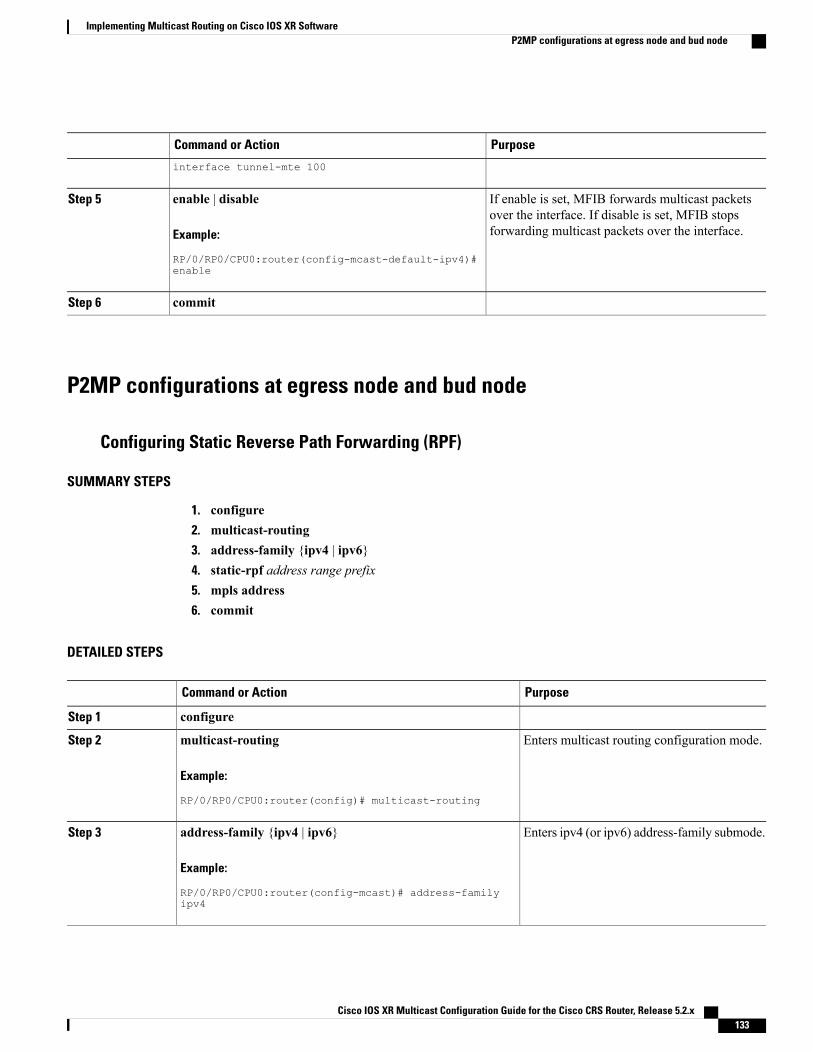
PurposeCommand or Action
interface tunnel-mte 100
If enable is set, MFIB forwards multicast packetsover the interface. If disable is set, MFIB stopsforwarding multicast packets over the interface.
enable | disable
Example:
RP/0/RP0/CPU0:router(config-mcast-default-ipv4)#
Step 5
enable
commitStep 6
P2MP configurations at egress node and bud node
Configuring Static Reverse Path Forwarding (RPF)
SUMMARY STEPS
1. configure2. multicast-routing3. address-family {ipv4 | ipv6}4. static-rpf address range prefix5. mpls address6. commit
DETAILED STEPS
PurposeCommand or Action
configureStep 1
Enters multicast routing configuration mode.multicast-routing
Example:
RP/0/RP0/CPU0:router(config)# multicast-routing
Step 2
Enters ipv4 (or ipv6) address-family submode.address-family {ipv4 | ipv6}
Example:
RP/0/RP0/CPU0:router(config-mcast)# address-family
Step 3
ipv4
Cisco IOS XR Multicast Configuration Guide for the Cisco CRS Router, Release 5.2.x 133
Implementing Multicast Routing on Cisco IOS XR SoftwareP2MP configurations at egress node and bud node

PurposeCommand or Action
Enter the source and prefix length.static-rpf address range prefix
Example:
RP/0/RP0/CPU0:router(config-mcast-default-ipv4)#
Step 4
static-rpf 10.1.1.1 32
Enter the source PE address of the MPLSP2MP tunnel.
mpls address
Example:
RP/0/RP0/CPU0:router(config-mcast-default-ipv4)# mpls
Step 5
10.2.2.2
commitStep 6
Configuring Core Tree Protocol
SUMMARY STEPS
1. configure2. multicast-routing3. address-family {ipv4 | ipv6}4. core-tree-protocol rsvp-te group-list name5. commit
DETAILED STEPS
PurposeCommand or Action
configureStep 1
Enters multicast routing configuration mode.multicast-routing
Example:
RP/0/RP0/CPU0:router(config)# multicast-routing
Step 2
Enters ipv4 (or ipv6)address-family submode.address-family {ipv4 | ipv6}
Example:
RP/0/RP0/CPU0:router(config-mcast)# address-family ipv4
Step 3
Cisco IOS XR Multicast Configuration Guide for the Cisco CRS Router, Release 5.2.x134
Implementing Multicast Routing on Cisco IOS XR SoftwareP2MP configurations at egress node and bud node

PurposeCommand or Action
Enters the core-tree-protocol configurationmode.
core-tree-protocol rsvp-te group-list name
Example:
RP/0/RP0/CPU0:router(config-mcast-default-ipv4)#
Step 4
core-tree-protocol rsvp-te group-list acl1
commitStep 5
Configuration Examples for Implementing Multicast Routing onSoftware
This section provides the following configuration examples:
MSDP Anycast RP Configuration on Cisco IOS XR Software: ExampleAnycast RP allows two or more rendezvous points (RPs) to share the load for source registration and to actas hot backup routers for each other. MSDP is the key protocol that makes Anycast RP possible.
In Anycast RP, two or more RPs are configured with the same IP address on loopback interfaces. Configurethe Anycast RP loopback address with a 32-bit mask, making it a host address. Configure all downstreamrouters to “know” that the Anycast RP loopback address is the IP address of the local RP. IP routingautomatically selects the topologically closest RP for each source and receiver.
As a source may register with one RP and receivers may join to a different RP, a method is needed for theRPs to exchange information about active sources. This information exchange is done with MSDP.
In Anycast RP, all the RPs are configured to be MSDP peers of each other. When a source registers with oneRP, a Source-Active (SA) message is sent to the other RPs, informing them that there is an active source fora particular multicast group. The result is that each RP knows about the active sources in the area of the otherRPs. If any of the RPs fails, IP routing converges and one of the RPs becomes the active RP in more than onearea. New sources register with the backup RP, and receivers join the new RP.
Note that the RP is usually needed only to start new sessions with sources and receivers. The RP facilitatesthe shared tree so that sources and receivers can directly establish a multicast data flow. If a multicast dataflow is already directly established between a source and the receiver, an RP failure does not affect that session.Anycast RP ensures that new sessions with sources and receivers can begin at any time.
The following Anycast RP example configures Router A and Router B as Anycast RPs. The Anycast RP IPaddress assignment is 10.0.0.1.
Router A
interface loopback 0ipv4 address 10.0.0.1/32no shutdowninterface loopback 1
Cisco IOS XR Multicast Configuration Guide for the Cisco CRS Router, Release 5.2.x 135
Implementing Multicast Routing on Cisco IOS XR SoftwareConfiguration Examples for Implementing Multicast Routing on Software

ipv4 address 10.2.0.1/32no shutdownmulticast-routinginterfaces all enablerouter pimrp-address 10.0.0.1router msdpconnect-source loopback 1peer 10.2.0.2
Router B
interface loopback 0ipv4 address 10.0.0.1/32no shutdowninterface loopback 1ipv4 address 10.2.0.2/32no shutdownmulticast-routinginterfaces all enablerouter pimrp-address 10.0.0.1router msdpconnect-source loopback 1peer 10.2.0.1
Apply the following configuration to all network routers:
multicast-routingrouter pimrp-address 10.0.0.1
Bidir-PIM Configuration on Software: ExampleAn access list on the RP can be used to specify a list of groups to be advertised as bidirectional PIM (bidir-PIM).
The following example shows how to configure an RP for both PIM-SM and the bidir-PIMmode groups. Thebidir-PIM groups are configured as 224/8 and 227/8, with the remaining multicast group range (224/4)configured as PIM-SM.
interface loopback 0ipv4 address 10.0.0.1/24no shutdowninterface loopback 1ipv4 address 10.2.0.1/24no shutdownipv4 access-list bidir_acl10 permit 224.0.0.0 0.255.255.255 any20 permit 225.0.0.0 0.255.255.255 anymulticast-routinginterface all enablerouter pimauto-rp mapping-agent loopback 0 scope 15 interval 60auto-rp candidate-rp loopback 0 scope 15 group-list bidir_acl interval 60 bidirauto-rp candidate-rp loopback 1 scope 15 group-list 224/4 interval 60
Issue the show pim group-map command and verify the output to ensure that the configured mappingsare learned correctly.
Tip
Cisco IOS XR Multicast Configuration Guide for the Cisco CRS Router, Release 5.2.x136
Implementing Multicast Routing on Cisco IOS XR SoftwareBidir-PIM Configuration on Software: Example

Calculating Rates per Route: ExampleThe following example illustrates output from hardware counters based on rate per route for a specific sourceand group address location:
RP/0/RP0/CPU0:router# configureRP/0/RP0/CPU0:router(config)# multicast-routing vrf vpn12 address-family ipv4RP/0/RP0/CPU0:router(config-mcast-default-ipv4)# rate-per-routeRP/0/RP0/CPU0:router(config-mcast-default-ipv4)# interface all enableRP/0/RP0/CPU0:router(config-mcast-default-ipv4)# accounting per-prefixRP/0/RP0/CPU0:router(config-mcast-default-ipv4)# commitRP/0/RP0/CPU0:router(config-mcast-default-ipv4)# exitRP/0/RP0/CPU0:router(config-mcast)# exitRP/0/RP0/CPU0:router(config)# exitRP/0/RP0/CPU0:router# show mfib route rate
IP Multicast Forwarding Rates Source Address, Group Address HW Forwarding Rates: bps In/ppsIn/bps Out/pps Out
(*,224.0.0.0/24)bps_in /pps_in /bps_out /pps_outN/A / N/A / N/A / N/A
(*,224.0.1.39)bps_in /pps_in /bps_out /pps_outN/A / N/A / N/A / N/A
(*,224.0.1.40)bps_in /pps_in /bps_out /pps_outN/A / N/A / N/A / N/A
(*,232.0.0.0/8)bps_in /pps_in /bps_out /pps_outN/A / N/A / N/A / N/A(30.0.70.2,225.0.0.0)bps_in /pps_in /bps_out /pps_out22649 / 50 / 22951 / 50
(30.0.70.2,225.0.0.1)bps_in /pps_in /bps_out /pps_out22649 / 50 / 22951 / 50
(30.0.70.2,225.0.0.2)bps_in /pps_in /bps_out /pps_out22649 / 50 / 22951 / 50
(30.0.70.2,225.0.0.3)bps_in /pps_in /bps_out /pps_out22649 / 50 / 22951 / 50
(30.0.70.2,225.0.0.4)bps_in /pps_in /bps_out /pps_out22649 / 50 / 22951 / 50
(30.0.70.2,225.0.0.5)bps_in /pps_in /bps_out /pps_out22649 / 50 / 22951 / 50
(30.0.70.2,225.0.0.6)bps_in /pps_in /bps_out /pps_out
Cisco IOS XR Multicast Configuration Guide for the Cisco CRS Router, Release 5.2.x 137
Implementing Multicast Routing on Cisco IOS XR SoftwareCalculating Rates per Route: Example

Preventing Auto-RP Messages from Being Forwarded on Software: ExampleThis example shows that Auto-RPmessages are prevented from being sent out of the Packet over SONET/SDH(POS) interface 0/3/0/0. It also shows that access list 111 is used by the Auto-RP candidate and access list222 is used by the boundary command to contain traffic on POS interface 0/3/0/0.
ipv4 access-list 11110 permit 224.1.0.0 0.0.255.255 any20 permit 224.2.0.0 0.0.255.255 any!!Access list 111 is used by the Auto-RP candidate.!ipv4 access-list 22210 deny any host 224.0.1.3920 deny any host 224.0.1.40!!Access list 222 is used by the boundary command to contain traffic (on POS0/3/0/0) thatis sent to groups 224.0.1.39 and 224.0.1.40.!router pimauto-rp mapping-agent loopback 2 scope 32 interval 30auto-rp candidate-rp loopback 2 scope 15 group-list 111 interval 30multicast-routinginterface pos 0/3/0/0boundary 222!
Inheritance in MSDP on Software: ExampleThe following MSDP commands can be inherited by all MSDP peers when configured under router MSDPconfiguration mode. In addition, commands can be configured under the peer configuration mode for specificpeers to override the inheritance feature.
• connect-source
• sa-filter
• ttl-threshold
If a command is configured in both the router msdp and peer configuration modes, the peer configurationtakes precedence.
In the following example, MSDP on Router A filters Source-Active (SA) announcements on all peer groupsin the address range 226/8 (except IP address 172.16.0.2); and filters SAs sourced by the originator RP172.16.0.3 to 172.16.0.2.
MSDP peers (172.16.0.1, 172.16.0.2, and 172.17.0.1) use the loopback 0 address of Router A to set up peering.However, peer 192.168.12.2 uses the IPv4 address configured on the Packet-over-SONET/SDH (POS) interfaceto peer with Router A.
Router A
!ipv4 access-list 11110 deny ip host 172.16.0.3 any20 permit any any!
Cisco IOS XR Multicast Configuration Guide for the Cisco CRS Router, Release 5.2.x138
Implementing Multicast Routing on Cisco IOS XR SoftwarePreventing Auto-RP Messages from Being Forwarded on Software: Example

ipv4 access-list 11210 deny any 226.0.0.0 0.255.255.25530 permit any any!router msdpconnect-source loopback 0sa-filter in rp-list 111sa-filter out rp-list 111peer 172.16.0.1!peer 172.16.0.2sa-filter out list 112!peer 172.17.0.1!peer 192.168.12.2connect-source pos 0/2/0/0!
MSDP-VRF: Example
This is an example where, peer 1.1.1.1 is configured in the VRF context for vrf1.configrouter msdpvrf vrf1peer 1.1.1.1
exitend!
•
Configuring Route Policy for Static RPF: Example
router staticaddress-family ipv4 multicast202.93.192.74 /32 202.40.148.11
!route-policy pim-policyset rpf-topology ipv4 multicast topology default
end-policy!router pimaddress-family ipv4rpf topology route-policy pim-policy
Configuring IPv4 Multicast VPN: ExampleCisco CRS Routers support only IPv4 addressing.
Cisco IOS XR Multicast Configuration Guide for the Cisco CRS Router, Release 5.2.x 139
Implementing Multicast Routing on Cisco IOS XR SoftwareMSDP-VRF: Example

This end-to-end configuration example shows how to establish a multicast VPN topology (Figure 10: Topologyin CE4PE1PE2 CE3MVPN Configuration, on page 140), using two different routing protocols (OSPF orBGP) to broadcasting traffic between customer-edge(CE) routers and provider-edge (PE) routers:
Figure 10: Topology in CE4PE1PE2 CE3MVPN Configuration
CE4------------------ PE1 ------------------------------------------------ PE2 ------------------ CE3
For more configuration information, see the ConfiguringMulticast VPN, on page 100 of this module and alsorelated configuration information in Cisco IOS XR Routing Configuration Guide for the Cisco CRS Router .
Configuring MVPN to Advertise Routes Between the CE and the PE Using OSPF: Example
PE1:
!vrf vpn1address-family ipv4 unicastimport route-target1:1!export route-target1:1!!!interface Loopback0ipv4 address 1.1.1.1 255.255.255.255!interface Loopback1vrf vpn1ipv4 address 2.2.2.2 255.255.255.255!interface GigabitEthernet0/5/0/0vrf vpn1ipv4 address 101.1.1.1 255.255.255.0!interface TenGigE0/6/0/0ipv4 address 12.1.1.1 255.255.255.0!mpls ldprouter-id 1.1.1.1interface TenGigE0/6/0/0!!multicast-routingvrf vpn1 address-family ipv4mdt data 233.1.0.0/16 threshold 3mdt default ipv4 232.1.1.1rate-per-routeinterface all enableaccounting per-prefix!address-family ipv4nsfmdt source Loopback0interface all enableaccounting per-prefix!!router bgp 100bgp router-id 1.1.1.1address-family ipv4 unicast!address-family vpnv4 unicast
Cisco IOS XR Multicast Configuration Guide for the Cisco CRS Router, Release 5.2.x140
Implementing Multicast Routing on Cisco IOS XR SoftwareConfiguring IPv4 Multicast VPN: Example

!address-family ipv4 mdt!neighbor 9.9.9.9remote-as 100update-source Loopback0address-family ipv4 unicast!address-family vpnv4 unicast!address-family ipv4 mdt!!vrf vpn1rd 1:1address-family ipv4 unicastredistribute ospf 1!!!router ospf 1vrf vpn1router-id 2.2.2.2redistribute bgp 100area 0interface Loopback1!interface GigabitEthernet0/5/0/0!!!!router ospf 100router-id 1.1.1.1area 0interface Loopback0!interface TenGigE0/6/0/0!!!router pim vrf vpn1 address-family ipv4rp-address 2.2.2.2log neighbor changes!router pim vrf default address-family ipv4rp-address 1.1.1.1!end
PE2:
!vrf vpn1address-family ipv4 unicastimport route-target1:1!export route-target1:1!!!interface Loopback0ipv4 address 9.9.9.9 255.255.255.255!interface Loopback1vrf vpn1ipv4 address 10.10.10.10 255.255.255.255!
Cisco IOS XR Multicast Configuration Guide for the Cisco CRS Router, Release 5.2.x 141
Implementing Multicast Routing on Cisco IOS XR SoftwareConfiguring IPv4 Multicast VPN: Example

interface GigabitEthernet0/2/2/7vrf vpn1ipv4 address 122.1.1.1 255.255.255.0negotiation auto!interface TenGigE0/3/0/0ipv4 address 12.1.1.2 255.255.255.0!mpls ldprouter-id 9.9.9.9interface TenGigE0/3/0/0!!multicast-routingvrf vpn1 address-family ipv4mdt data 233.1.0.0/16 threshold 3mdt default ipv4 232.1.1.1rate-per-routeinterface all enableaccounting per-prefix!address-family ipv4nsfmdt source Loopback0interface all enableaccounting per-prefix!!router bgp 100bgp router-id 9.9.9.9address-family ipv4 unicast!address-family vpnv4 unicast!address-family ipv4 mdt!neighbor 1.1.1.1remote-as 100update-source Loopback0address-family ipv4 unicast!address-family vpnv4 unicast!address-family ipv4 mdt!!vrf vpn1rd 1:1address-family ipv4 unicastredistribute ospf 1!!!router ospf 1vrf vpn1router-id 10.10.10.10redistribute bgp 100area 0interface Loopback1!interface GigabitEthernet0/2/2/7!!!!router ospf 100router-id 9.9.9.9area 0interface Loopback0!interface TenGigE0/3/0/0!!
Cisco IOS XR Multicast Configuration Guide for the Cisco CRS Router, Release 5.2.x142
Implementing Multicast Routing on Cisco IOS XR SoftwareConfiguring IPv4 Multicast VPN: Example

!router pim vrf vpn1 address-family ipv4rp-address 2.2.2.2!router pim vrf default address-family ipv4rp-address 1.1.1.1!end
CE4:
For information about configuring the CE router, using Cisco IOS software, see the appropriate Cisco IOSsoftware configuration documentation.
!interface Loopback0ipv4 address 101.101.101.101 255.255.255.255!interface GigabitEthernet0/0/0/0ipv4 address 101.1.1.2 255.255.255.0!interface GigabitEthernet0/0/0/3ipv4 address 11.1.1.1 255.255.255.0!multicast-routingaddress-family ipv4interface all enable!!router ospf 1router-id 101.101.101.101area 0interface Loopback0!interface GigabitEthernet0/0/0/0!interface GigabitEthernet0/0/0/3!!!router pim vrf default address-family ipv4rp-address 2.2.2.2interface Loopback0!interface GigabitEthernet0/0/0/0!interface GigabitEthernet0/0/0/3!!end
CE3:
For information about configuring the CE router, using Cisco IOS software, see the appropriate Cisco IOSsoftware configuration documentation.
interface Loopback0ipv4 address 122.122.122.122 255.255.255.255!
interface GigabitEthernet0/1/3/0ipv4 address 22.1.1.1 255.255.255.0!
interface GigabitEthernet0/2/3/0ipv4 address 122.1.1.2 255.255.255.0
Cisco IOS XR Multicast Configuration Guide for the Cisco CRS Router, Release 5.2.x 143
Implementing Multicast Routing on Cisco IOS XR SoftwareConfiguring IPv4 Multicast VPN: Example

multicast-routingaddress-family ipv4interface all enable
!router ospf 1router-id 122.122.122.122area 0interface Loopback0!interface GigabitEthernet0/1/3/0!interface GigabitEthernet0/2/3/0!!!router pim vrf default address-family ipv4rp-address 2.2.2.2interface Loopback0!interface GigabitEthernet0/1/3/0!interface GigabitEthernet0/2/3/0!!end
Configuring MVPN to Advertise Routes Between the CE and the PE Using BGP: Example
PE1:
vrf vpn1address-family ipv4 unicastimport route-target1:1!export route-target1:1!!!interface Loopback0ipv4 address 1.1.1.1 255.255.255.255!interface Loopback1vrf vpn1ipv4 address 2.2.2.2 255.255.255.255!interface GigabitEthernet0/5/0/0vrf vpn1ipv4 address 101.1.1.1 255.255.255.0!interface TenGigE0/6/0/0ipv4 address 12.1.1.1 255.255.255.0!mpls ldprouter-id 1.1.1.1interface TenGigE0/6/0/0!!multicast-routingvrf vpn1 address-family ipv4mdt data 233.1.0.0/16 threshold 3mdt default ipv4 232.1.1.1rate-per-routeinterface all enableaccounting per-prefix!address-family ipv4
Cisco IOS XR Multicast Configuration Guide for the Cisco CRS Router, Release 5.2.x144
Implementing Multicast Routing on Cisco IOS XR SoftwareConfiguring IPv4 Multicast VPN: Example

nsfmdt source Loopback0interface all enableaccounting per-prefix!!!route-policy pass-allpass
end-policy!router bgp 100bgp router-id 1.1.1.1address-family ipv4 unicast!address-family vpnv4 unicast!address-family ipv4 mdt!neighbor 9.9.9.9remote-as 100update-source Loopback0address-family ipv4 unicast!address-family vpnv4 unicast!address-family ipv4 mdt!!vrf vpn1rd 1:1address-family ipv4 unicastredistribute connected!neighbor 101.1.1.2remote-as 400address-family ipv4 unicastroute-policy pass-all inroute-policy pass-all out!!!!router ospf 100router-id 1.1.1.1area 0interface Loopback0!interface TenGigE0/6/0/0!!!router pim vrf vpn1 address-family ipv4rp-address 2.2.2.2log neighbor changes!router pim vrf default address-family ipv4rp-address 1.1.1.1!end
PE2:
!vrf vpn1address-family ipv4 unicastimport route-target1:1!export route-target
Cisco IOS XR Multicast Configuration Guide for the Cisco CRS Router, Release 5.2.x 145
Implementing Multicast Routing on Cisco IOS XR SoftwareConfiguring IPv4 Multicast VPN: Example

1:1!!!interface Loopback0ipv4 address 9.9.9.9 255.255.255.255!interface Loopback1vrf vpn1ipv4 address 10.10.10.10 255.255.255.255!interface GigabitEthernet0/2/2/7vrf vpn1ipv4 address 122.1.1.1 255.255.255.0negotiation auto!interface TenGigE0/3/0/0ipv4 address 12.1.1.2 255.255.255.0!mpls ldprouter-id 9.9.9.9interface TenGigE0/3/0/0!!multicast-routingvrf vpn1 address-family ipv4mdt data 233.1.0.0/16 threshold 3mdt default ipv4 232.1.1.1rate-per-routeinterface all enableaccounting per-prefix!address-family ipv4nsfmdt source Loopback0interface all enableaccounting per-prefix!!!route-policy pass-allpass
end-policy!router bgp 100bgp router-id 9.9.9.9address-family ipv4 unicast!address-family vpnv4 unicast!address-family ipv4 mdt!neighbor 1.1.1.1remote-as 100update-source Loopback0address-family ipv4 unicast!address-family vpnv4 unicast!address-family ipv4 mdt!!vrf vpn1rd 1:1address-family ipv4 unicastredistribute connected!neighbor 122.1.1.2remote-as 500address-family ipv4 unicastroute-policy pass-all inroute-policy pass-all out!
Cisco IOS XR Multicast Configuration Guide for the Cisco CRS Router, Release 5.2.x146
Implementing Multicast Routing on Cisco IOS XR SoftwareConfiguring IPv4 Multicast VPN: Example

!!!router ospf 100router-id 9.9.9.9area 0interface Loopback0!interface TenGigE0/3/0/0!!!router pim vrf vpn1 address-family ipv4rp-address 2.2.2.2!router pim vrf default address-family ipv4rp-address 1.1.1.1!end
CE4:
For information about configuring the CE router, using Cisco IOS software, see the appropriate Cisco IOSsoftware configuration documentation.
interface Loopback0ipv4 address 101.101.101.101 255.255.255.255!interface GigabitEthernet0/0/0/0ipv4 address 101.1.1.2 255.255.255.0!interface GigabitEthernet0/0/0/3ipv4 address 11.1.1.1 255.255.255.0!multicast-routingaddress-family ipv4interface all enable!!!route-policy pass-allpass
end-policy!router bgp 400bgp router-id 101.101.101.101address-family ipv4 unicastredistribute connected!neighbor 101.1.1.1remote-as 100address-family ipv4 unicastroute-policy pass-all inroute-policy pass-all out!!!router pim vrf default address-family ipv4rp-address 2.2.2.2interface Loopback0!interface GigabitEthernet0/0/0/0!interface GigabitEthernet0/0/0/3!!end
Cisco IOS XR Multicast Configuration Guide for the Cisco CRS Router, Release 5.2.x 147
Implementing Multicast Routing on Cisco IOS XR SoftwareConfiguring IPv4 Multicast VPN: Example

CE3:
For information about configuring the CE router, using Cisco IOS software, see the appropriate Cisco IOSsoftware configuration documentation.
interface Loopback0ipv4 address 122.122.122.122 255.255.255.255!
interface GigabitEthernet0/1/3/0ipv4 address 22.1.1.1 255.255.255.0!
interface GigabitEthernet0/2/3/0ipv4 address 122.1.1.2 255.255.255.0
multicast-routingaddress-family ipv4interface all enable
!!!route-policy pass-allpass
end-policy!router bgp 500bgp router-id 122.122.122.122address-family ipv4 unicastredistribute connected!neighbor 122.1.1.1remote-as 100address-family ipv4 unicastroute-policy pass-all inroute-policy pass-all out!!!!router pim vrf default address-family ipv4rp-address 2.2.2.2interface Loopback0!interface GigabitEthernet0/1/3/0!interface GigabitEthernet0/2/3/0!!end
Configuration Examples for MVPN ProfilesThe profile-wise configuration examples for the various MVPN profiles.
Configuration Examples for Inband mLDP profilesProfile-6: VRF Inband mLDProuter bgp 100mvpn!multicast-routingmdt source Loopback0vrf v61
Cisco IOS XR Multicast Configuration Guide for the Cisco CRS Router, Release 5.2.x148
Implementing Multicast Routing on Cisco IOS XR SoftwareConfiguration Examples for MVPN Profiles

address-family ipv4mdt mtu 1600mdt mldp in-band-signaling ipv4interface all enable!address-family ipv6mdt mtu 1600mdt mldp in-band-signaling ipv4interface all enable
!!router pimvrf v61address-family ipv4rpf topology route-policy mldp-inband!address-family ipv6rpf topology route-policy mldp-inband!
!route-policy mldp-inbandset core-tree mldp-inband
end-policy!Profile-7: Global Inband mLDPmulticast-routingaddress-family ipv4mdt source Loopback0mdt mldp in-band-signaling ipv4ssm range Global-SSM-Groupinterface all enable
!address-family ipv6mdt source Loopback0mdt mldp in-band-signaling ipv4ssm range Global-SSM-Group-V6interface all enable
!router pimaddress-family ipv4rpf topology route-policy mldp-inband!address-family ipv6rpf topology route-policy mldp-inband
!!route-policy mldp-inbandset core-tree mldp-inband
end-policy!
Configuration Examples for P2MP-TE profilesProfile-8: Global Static P2MP-TEinterface Loopback0ipv4 address 200.200.1.1 255.255.255.255!multicast-routingaddress-family ipv4mdt source Loopback0ssm range Global-SSM-Groupinterface all enable
!address-family ipv6mdt source Loopback0ssm range Global-SSM-Group-V6interface all enable
!router igmp
Cisco IOS XR Multicast Configuration Guide for the Cisco CRS Router, Release 5.2.x 149
Implementing Multicast Routing on Cisco IOS XR SoftwareConfiguration Examples for MVPN Profiles

interface tunnel-mte1static-group 228.1.1.1 2.2.2.1
!router mldinterface tunnel-mte1static-group ff3e:0:228::1 2001:2:2:2::1
Profile-10: VRF static P2MP-TE with BGP-AD
!multicast-routingmdt source Loopback0vrf v101address-family ipv4mdt static p2mp-te tunnel-mte10interface all enablebgp auto-discovery pim!
!router igmpvrf v101interface tunnel-mte10static-group 227.101.1.1 101.7.1.1
!!
Profile-18: Rosen Static P2MP-TE with BGP-AD and PIM signalingmulticast-routingmdt source Loopback0vrf v181address-family ipv4mdt default p2mp-te static tunnel-mte18interface all enablebgp auto-discovery pim!address-family ipv6mdt default p2mp-te static tunnel-mte181interface all enablebgp auto-discovery pim
!!router pimvrf v181address-family ipv4rpf topology route-policy p2mp-te-default!
address-family ipv6rpf topology route-policy p2mp-te-default!
!route-policy p2mp-te-defaultset core-tree p2mp-te-default
end-policy!
Profile-16: Rosen Static P2MP-TE with BGP-Ad and BGP signaling!multicast-routingmdt source Loopback0vrf v161address-family ipv4mdt default p2mp-te static tunnel-mte16interface all enablebgp auto-discovery pim!address-family ipv6mdt default p2mp-te static tunnel-mte161interface all enablebgp auto-discovery pim
!!
Cisco IOS XR Multicast Configuration Guide for the Cisco CRS Router, Release 5.2.x150
Implementing Multicast Routing on Cisco IOS XR SoftwareConfiguration Examples for MVPN Profiles

router pimvrf v161address-family ipv4rpf topology route-policy p2mp-te-defaultmdt c-multicast-routing bgp!address-family ipv6rpf topology route-policy p2mp-te-defaultmdt c-multicast-routing bgp
!!route-policy p2mp-te-defaultset core-tree p2mp-te-default
end-policy!Profile-20: Default MDT - P2MP-TE - BGP-AD - PIM
multicast-routingmdt source Loopback0vrf p20_vrf1address-family ipv4 unicastimport route-target20:1!export route-target20:1!
route-policy rpf-for-p20_vrf1set core-tree p2mp-te-default
end-policy!vrf p20_vrf1rd 20:1address-family ipv4 unicastredistribute connected!address-family ipv4 mvpn!!rsvpinterface Bundle-Ether1bandwidth!!vrf p20_vrf1address-family ipv4mdt source Loopback0rate-per-routeinterface all enableaccounting per-prefixbgp auto-discovery p2mp-te!mdt default p2mp-te!!vrf p20_vrf1address-family ipv4rpf topology route-policy rpf-for-p20_vrf1rp-address 100.1.20.1 static_p20vrf1_v4log neighbor changesinterface GigabitEthernet0/0/0/0.202enable!interface GigabitEthernet0/0/0/0.203enable!interface GigabitEthernet0/0/0/1.202enable!interface GigabitEthernet0/0/0/1.203enable!
Cisco IOS XR Multicast Configuration Guide for the Cisco CRS Router, Release 5.2.x 151
Implementing Multicast Routing on Cisco IOS XR SoftwareConfiguration Examples for MVPN Profiles

Configuration examples for Partitioned mLDP profilesProfile-2: Partitioned mLDP MP2MP without BGP-AD
router bgp 100mvpn
!multicast-routingvrf v21address-family ipv4mdt mtu 1600mdt partitioned mldp ipv4 mp2mpinterface all enable!address-family ipv6mdt mtu 1600mdt partitioned mldp ipv4 mp2mpinterface all enable
!!router pimvrf v21address-family ipv4rpf topology route-policy mldp-partitioned-mp2mp!address-family ipv6rpf topology route-policy mldp-partitioned-mp2mp
!!route-policy mldp-partitioned-mp2mpset core-tree mldp-partitioned-mp2mp
end-policy!Profile-4: Partitioned mLDP MP2MP with BGP-AD and PIM signaling!multicast-routingmdt source Loopback0vrf v41address-family ipv4mdt mtu 1600
mdt partitioned mldp ipv4 mp2mpmdt data 255
interface all enablebgp auto-discovery mldp!address-family ipv6mdt mtu 1600
mdt partitioned mldp ipv4 mp2mpmdt data 255
interface all enablebgp auto-discovery mldp!
!router pimvrf v41address-family ipv4rpf topology route-policy mldp-partitioned-mp2mp!address-family ipv6rpf topology route-policy mldp-partitioned-mp2mp
!!route-policy mldp-partitioned-mp2mpset core-tree mldp-partitioned-mp2mp
end-policy!
Cisco IOS XR Multicast Configuration Guide for the Cisco CRS Router, Release 5.2.x152
Implementing Multicast Routing on Cisco IOS XR SoftwareConfiguration Examples for MVPN Profiles
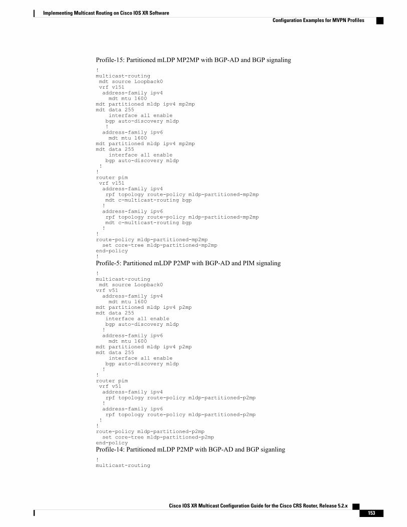
Profile-15: Partitioned mLDP MP2MP with BGP-AD and BGP signaling!multicast-routingmdt source Loopback0vrf v151address-family ipv4mdt mtu 1600
mdt partitioned mldp ipv4 mp2mpmdt data 255
interface all enablebgp auto-discovery mldp!address-family ipv6mdt mtu 1600
mdt partitioned mldp ipv4 mp2mpmdt data 255
interface all enablebgp auto-discovery mldp
!!router pimvrf v151address-family ipv4rpf topology route-policy mldp-partitioned-mp2mpmdt c-multicast-routing bgp!address-family ipv6rpf topology route-policy mldp-partitioned-mp2mpmdt c-multicast-routing bgp!
!route-policy mldp-partitioned-mp2mpset core-tree mldp-partitioned-mp2mp
end-policy!Profile-5: Partitioned mLDP P2MP with BGP-AD and PIM signaling!multicast-routingmdt source Loopback0vrf v51address-family ipv4mdt mtu 1600
mdt partitioned mldp ipv4 p2mpmdt data 255
interface all enablebgp auto-discovery mldp!address-family ipv6mdt mtu 1600
mdt partitioned mldp ipv4 p2mpmdt data 255
interface all enablebgp auto-discovery mldp!
!router pimvrf v51address-family ipv4rpf topology route-policy mldp-partitioned-p2mp!address-family ipv6rpf topology route-policy mldp-partitioned-p2mp
!!route-policy mldp-partitioned-p2mpset core-tree mldp-partitioned-p2mp
end-policyProfile-14: Partitioned mLDP P2MP with BGP-AD and BGP siganling!multicast-routing
Cisco IOS XR Multicast Configuration Guide for the Cisco CRS Router, Release 5.2.x 153
Implementing Multicast Routing on Cisco IOS XR SoftwareConfiguration Examples for MVPN Profiles

mdt source Loopback0vrf v141address-family ipv4mdt mtu 1600mdt partitioned mldp ipv4 p2mpmdt data 255interface all enablebgp auto-discovery mldp!address-family ipv6mdt mtu 1600
mdt partitioned mldp ipv4 p2mpmdt data 255
interface all enablebgp auto-discovery mldp
!!router pimvrf v141address-family ipv4rpf topology route-policy mldp-partitioned-p2mpmdt c-multicast-routing bgp!address-family ipv6rpf topology route-policy mldp-partitioned-p2mpmdt c-multicast-routing bgp
!!route-policy mldp-partitioned-p2mpset core-tree mldp-partitioned-p2mp
end-policy!
Configuration Examples for Rosen-mGRE profiles
Profile-0: Rosen mGRE with MDT SAFIrouter bgp 100address-family ipv4 mdt!neighbor X.X.X.X < -----RR or Remote PE ip addressaddress-family ipv4 mdt!!
multicast-routingaddress-family ipv4mdt source Loopback0interface all enable
!address-family ipv6mdt source Loopback0interface all enable
!vrf v1address-family ipv4mdt mtu 1600mdt data 231.1.1.2/32mdt default ipv4 231.1.1.1interface all enable!address-family ipv6mdt mtu 1600mdt data 231.1.1.2/32mdt default ipv4 231.1.1.1interface all enable
!!
Cisco IOS XR Multicast Configuration Guide for the Cisco CRS Router, Release 5.2.x154
Implementing Multicast Routing on Cisco IOS XR SoftwareConfiguration Examples for MVPN Profiles

Profile-3: Rosen mGRE with BGP-AD and PIM signalingrouter bgp 100!address-family ipv4 mvpn!address-family ipv6 mvpn!neighbor X.X.X.X < -----RR or Remote PE ip addressaddress-family ipv4 mvpn!address-family ipv6 mvpn!!vrf v31rd 100:31address-family ipv4 mvpn!address-family ipv6 mvpn!!!multicast-routingmdt source Loopback0vrf v31address-family ipv4mdt mtu 1600mdt data 232.31.1.2/32mdt default ipv4 232.31.1.1interface all enablebgp auto-discovery pim!address-family ipv6mdt mtu 1600mdt data 232.31.1.2/32mdt default ipv4 232.31.1.1interface all enablebgp auto-discovery pim
!!Profile-11: Rosen mGRE with BGP-AD and BGP signalingrouter bgp 100!address-family ipv4 mvpn!address-family ipv6 mvpn!neighbor X.X.X.X < -----RR or Remote PE ip addressaddress-family ipv4 mvpn!address-family ipv6 mvpn!!vrf v111rd 100:111address-family ipv4 mvpn!address-family ipv6 mvpn!!!multicast-routingmdt source Loopback0vrf v111address-family ipv4mdt mtu 1600mdt data 232.111.1.2/32mdt default ipv4 232.111.1.1interface all enablebgp auto-discovery pim!address-family ipv6
Cisco IOS XR Multicast Configuration Guide for the Cisco CRS Router, Release 5.2.x 155
Implementing Multicast Routing on Cisco IOS XR SoftwareConfiguration Examples for MVPN Profiles

mdt mtu 1600mdt data 232.111.1.2/32mdt default ipv4 232.111.1.1interface all enablebgp auto-discovery pim
!!router pimvrf v111address-family ipv4mdt c-multicast-routing bgp!address-family ipv6mdt c-multicast-routing bgp
!
Configuration Examples for Rosen mLDP profilesProfile-1: Rosen mLDP with M2MP without BGP-ADvrf v11vpn id 100:11!router bgp 100mvpn
!multicast-routingmdt source Loopback0vrf v11address-family ipv4mdt mtu 1600mdt default mldp ipv4 100.100.1.1mdt default mldp ipv4 100.100.1.2mdt data 255interface all enable!address-family ipv6mdt mtu 1600mdt default mldp ipv4 100.100.1.1mdt default mldp ipv4 100.100.1.2mdt data 255interface all enable
!!router pimvrf v11address-family ipv4rpf topology route-policy rosen-mldp!address-family ipv6rpf topology route-policy rosen-mldp
!!route-policy rosen-mldpset core-tree mldp-default
end-policy!Profile-9: Rosen mLDP MP2MP with BGP-AD and PIM signalingvrf v91vpn id 100:91
!!multicast-routingmdt source Loopback0vrf v91address-family ipv4mdt mtu 1600mdt default mldp ipv4 100.100.1.1mdt default mldp ipv4 100.100.1.2
Cisco IOS XR Multicast Configuration Guide for the Cisco CRS Router, Release 5.2.x156
Implementing Multicast Routing on Cisco IOS XR SoftwareConfiguration Examples for MVPN Profiles

mdt data 255interface all enablebgp auto-discovery mldp!address-family ipv6mdt mtu 1600mdt default mldp ipv4 100.100.1.1mdt default mldp ipv4 100.100.1.2mdt data 255interface all enablebgp auto-discovery mldp!
!router pimvrf v91address-family ipv4rpf topology route-policy rosen-mldp!address-family ipv6rpf topology route-policy rosen-mldp!!route-policy rosen-mldpset core-tree mldp-default
end-policy
Profile-13: Rosen mLDP MP2MP with BGP-AD and BGP signalingvrf v131vpn id 100:131!
!multicast-routingmdt source Loopback0vrf v131address-family ipv4mdt mtu 1600mdt default mldp ipv4 100.100.1.1mdt default mldp ipv4 100.100.1.2mdt data 255interface all enablebgp auto-discovery mldp!address-family ipv6mdt mtu 1600mdt default mldp ipv4 100.100.1.1mdt default mldp ipv4 100.100.1.2mdt data 255interface all enablebgp auto-discovery mldp!
!router pimvrf v131address-family ipv4rpf topology route-policy rosen-mldpmdt c-multicast-routing bgp!address-family ipv6rpf topology route-policy rosen-mldpmdt c-multicast-routing bgp!
!route-policy rosen-mldpset core-tree mldp-default
end-policyProfile-17: Rosen mLDP P2MP with BGP-AD and PIM signaling
!multicast-routingmdt source Loopback0
Cisco IOS XR Multicast Configuration Guide for the Cisco CRS Router, Release 5.2.x 157
Implementing Multicast Routing on Cisco IOS XR SoftwareConfiguration Examples for MVPN Profiles

vrf v171address-family ipv4mdt mtu 1600
mdt default mldp p2mpmdt data 255
interface all enablebgp auto-discovery mldp!address-family ipv6mdt mtu 1600
mdt default mldp p2mpmdt data 255
interface all enablebgp auto-discovery mldp
!!router pimvrf v171address-family ipv4rpf topology route-policy rosen-mldp!address-family ipv6rpf topology route-policy rosen-mldp
!!route-policy rosen-mldpset core-tree mldp-default
end-policy!Profile-12: Rosen mLDP P2MP with BGP-AD and BGP signaling!multicast-routingmdt source Loopback0vrf v121address-family ipv4mdt mtu 1600
mdt default mldp p2mpmdt data 255
interface all enablebgp auto-discovery mldp!address-family ipv6mdt mtu 1600
mdt default mldp p2mpmdt data 255
interface all enablebgp auto-discovery mldp
!!router pimvrf v121address-family ipv4rpf topology route-policy rosen-mldpmdt c-multicast-routing bgp!address-family ipv6rpf topology route-policy rosen-mldpmdt c-multicast-routing bgp!!route-policy rosen-mldpset core-tree mldp-default
end-policy!
Cisco IOS XR Multicast Configuration Guide for the Cisco CRS Router, Release 5.2.x158
Implementing Multicast Routing on Cisco IOS XR SoftwareConfiguration Examples for MVPN Profiles

Configuring Multitopology Routing: ExampleThe following example shows the configuration required to enable a dual multicast topology. The two topologiesdefined are named BLUE and GREEN. Each contains one interface. IS-IS is configured so that each interfaceis only in the IS-IS topology, and the interfaces themselves are configured so that their connected and localroutes are placed only within the appropriate routing tables.
The routing policy was configured to select which topology should be used based on the source address ofthe multicast flow.
!interface GigabitEthernet0/1/0/0address-family ipv4 multicast topology BLUE!interface GigabitEthernet0/1/0/1address-family ipv4 multicast topology GREEN!router isis 1net 00.0000.0000.0001.00interface GigabitEthernet0/1/0/0address-family ipv4 multicast topology BLUEinterface GigabitEthernet0/1/0/1address-family ipv4 multicast topology GREEN
!
route-policy mtp1if destination in (230.5.1.2) thenif source in (10.10.10.10) thenset rpf-topology ipv4 multicast topology BLUE
elseset rpf-topology ipv4 multicast topology GREEN
endifendif
end-policy!
router pimaddress-family ipv4rpf topology route-policy mtp1!!
multicast-routingaddress-family ipv4interface all enable!!
Examples 1 and 2 illustrate routing policies that you can use in configuring PIM RPF topologies:
Example 1
route-policy mtp1if destination in (225.0.0.1, 225.0.0.11) thenset rpf-topology ipv4 multicast topology t201
elseif destination in (225.0.0.2, 225.0.0.12) thenset rpf-topology ipv4 multicast topology t202
elseif destination in (225.0.0.3, 225.0.0.13) thenpass
endifend-policy!
Cisco IOS XR Multicast Configuration Guide for the Cisco CRS Router, Release 5.2.x 159
Implementing Multicast Routing on Cisco IOS XR SoftwareConfiguring Multitopology Routing: Example

Example 2
route-policy mtp2if destination in (225.0.0.8) thenset rpf-topology ipv4 multicast topology t208
elseif destination in (225.0.0.9) thenset rpf-topology ipv4 multicast topology t209
elseif destination in (225.0.0.10) thenset rpf-topology ipv4 multicast topology t210
elsedrop
endifend-policy!
Configuring MVPN Extranet Routing: ExampleThese examples describe two ways to configure MVPN extranet routing:
For the full set of configuration tasks, see Configuring MVPN Extranet Routing, on page 119.
Configuring the Source MVRF on the Receiver PE Router: ExampleThe following examples show how to configure MVPN extranet routing by specifying the source MVRF onthe receiver PE router.
You must configure both the source PE router and the receiver PE router.
Configure the Source PE Router Using Route Targets
interface Loopback5ipv4 address 201.5.5.201 255.255.255.255!interface Loopback22vrf provider-vrfipv4 address 201.22.22.201 255.255.255.255!interface GigabitEthernet0/6/0/0vrf provider-vrfipv4 address 10.10.10.1 255.255.0.0!vrf provider-vrfaddress-family ipv4 unicastimport route-target1100:1!export route-target1100:1!!router bgp 1regular BGP MVPN configvrf provider-vrfrd 1100:1address-family ipv4 unicastredistribute connected
!!multicast-routingvrf provider-vrf address-family ipv4mdt data 226.1.4.0/24 threshold 3log-traps
Cisco IOS XR Multicast Configuration Guide for the Cisco CRS Router, Release 5.2.x160
Implementing Multicast Routing on Cisco IOS XR SoftwareConfiguring MVPN Extranet Routing: Example

mdt default ipv4 226.0.0.4rate-per-routeinterface all enableaccounting per-prefix!!address-family ipv4nsfmdt source Loopback5interface all enable!!router pim vrf provider-vrf address-family ipv4rp-address 201.22.22.201!
Configure the Receiver PE Router Using Route Targets
interface Loopback5ipv4 address 202.5.5.202 255.255.255.255!interface GigabitEthernet0/3/0/2vrf receiver-vrfipv4 address 20.20.20.1 255.255.0.0!vrf provider-vrfaddress-family ipv4 unicastimport route-target1100:1!export route-target1100:1!!vrf receiver-vrfaddress-family ipv4 unicastimport route-target1100:11101:1!export route-target1101:1!!multicast-routingvrf provider-vrf address-family ipv4log-trapsmdt default ipv4 226.0.0.4rate-per-routeinterface all enableaccounting per-prefix!
vrf receiver_vrf address-family ipv4log-trapsmdt default ipv4 226.0.0.5rate-per-routeinterface all enableaccounting per-prefix!address-family ipv4nsfmdt source Loopback5interface all enable!router pim vrf provider-vrf address-family ipv4rp-address 201.22.22.201!
router pim vrf receiver_vrf address-family ipv4
Cisco IOS XR Multicast Configuration Guide for the Cisco CRS Router, Release 5.2.x 161
Implementing Multicast Routing on Cisco IOS XR SoftwareConfiguring MVPN Extranet Routing: Example

rp-address 201.22.22.201!router bgp 1regular BGP MVPN configvrf provider-vrfrd 1100:1address-family ipv4 unicastredistribute connected!
vrf receiver_vrfrd 1101:1address-family ipv4 unicastredistribute connected!
Configuring RPL Policies in Receiver VRFs to Propagate Joins to a Source VRF: Example
In addition to configuring route targets, Routing Policy Language (RPL) policies can be configured in receiverVRFs on receiver PE routers to propagate joins to a specified source VRF. However, this configuration isoptional.
The following configuration example shows a policy where the receiver VRF can pick either “provider_vrf_1”or “provider_vrf_2” to propogate PIM joins.
In this example, provider_vrf_1 is used for multicast streams in the range of from 227.0.0.0 to 227.255.255.255,while provider_vrf_2 is being used for streams in the range of from 228.0.0.0 to 228.255.255.255.
route-policy extranet_streams_from_provider_vrfif destination in (227.0.0.0/32 ge 8 le 32) thenset rpf-topology vrf provider_vrf_1elseif destination in (228.0.0.0/32 ge 8 le 32) thenset rpf-topology vrf provider_vrf_2elsepassendifend-policy!router pim vrf receiver_vrf address-family ipv4rpf topology route-policy extranet_streams_from_provider_vrf!
Configuring the Receiver MVRF on the Source PE Router: ExampleThe following examples show how to configure MVPN extranet routing by specifying the receiver MVRFon the source PE router.
You must configure both the source PE router and the receiver PE router.Note
Configure the Source PE Router Using Route Targets
interface Loopback5ipv4 address 202.5.5.202 255.255.255.255!interface GigabitEthernet0/3/0/2vrf provider-vrfipv4 address 20.20.20.1 255.255.0.0!
Cisco IOS XR Multicast Configuration Guide for the Cisco CRS Router, Release 5.2.x162
Implementing Multicast Routing on Cisco IOS XR SoftwareConfiguring MVPN Extranet Routing: Example
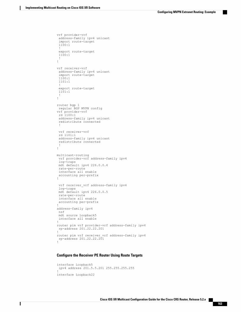
vrf provider-vrfaddress-family ipv4 unicastimport route-target1100:1!export route-target1100:1!!
vrf receiver-vrfaddress-family ipv4 unicastimport route-target1100:11101:1!export route-target1101:1!!
router bgp 1regular BGP MVPN configvrf provider-vrfrd 1100:1address-family ipv4 unicastredistribute connected!
vrf receiver-vrfrd 1101:1address-family ipv4 unicastredistribute connected!!
multicast-routingvrf provider-vrf address-family ipv4log-trapsmdt default ipv4 226.0.0.4rate-per-routeinterface all enableaccounting per-prefix!
vrf receiver_vrf address-family ipv4log-trapsmdt default ipv4 226.0.0.5rate-per-routeinterface all enableaccounting per-prefix!address-family ipv4nsfmdt source Loopback5interface all enable!router pim vrf provider-vrf address-family ipv4rp-address 201.22.22.201!router pim vrf receiver_vrf address-family ipv4rp-address 201.22.22.201!
Configure the Receiver PE Router Using Route Targets
interface Loopback5ipv4 address 201.5.5.201 255.255.255.255!interface Loopback22
Cisco IOS XR Multicast Configuration Guide for the Cisco CRS Router, Release 5.2.x 163
Implementing Multicast Routing on Cisco IOS XR SoftwareConfiguring MVPN Extranet Routing: Example

vrf receiver_vrfipv4 address 201.22.22.201 255.255.255.255!interface GigabitEthernet0/6/0/0vrf receiver_vrfipv4 address 10.10.10.1 255.255.0.0!
vrf receiver_vrfaddress-family ipv4 unicastimport route-target1100:11101:1!export route-target1101:1!!
router bgp 1regular BGP MVPN configvrf receiver_vrfrd 1101:1address-family ipv4 unicastredistribute connected!
multicast-routingvrf receiver_vrf address-family ipv4log-trapsmdt default ipv4 226.0.0.5rate-per-routeinterface all enableaccounting per-prefix!address-family ipv4nsfmdt source Loopback5interface all enable!
router pim vrf receiver_vrf address-family ipv4rp-address 201.22.22.201!
Configuring RPL Policies in Receiver VRFs on Source PE Routers to Propagate Joins to a Source VRF: Example
In addition to configuring route targets , RPL policies can be configured in receiver VRFs on a ource PErouter to propagate joins to a specified source VRF. However, this configuration is optional.
The configuration below shows a policy in which the receiver VRF can select either “provider_vrf_1” or“provider_vrf_2” to propagate PIM joins. Provider_vrf_1 will be selected if the rendezvous point (RP) for amulticast stream is 201.22.22.201, while provider_vrf_2 will be selected if the RP for a multicast stream is202.22.22.201.
As an alternative, you can configure a multicast group-based policy as shown in the Configuring RPL Policiesin Receiver VRFs to Propagate Joins to a Source VRF: Example, on page 162.
route-policy extranet_streams_from_provider_rpif source in (201.22.22.201) thenset rpf-topology vrf provider_vrf_1else if source in (202.22.22.201) thenset rpf-topology vrf provider_vrf_2elsepassendifend-policy!
Cisco IOS XR Multicast Configuration Guide for the Cisco CRS Router, Release 5.2.x164
Implementing Multicast Routing on Cisco IOS XR SoftwareConfiguring MVPN Extranet Routing: Example

router pim vrf receiver_vrf address-family ipv4rpf topology route-policy extranet_streams_from_provider_rprp-address 201.22.22.201 grange_227rp-address 202.22.22.201 grange_228!
Configuring Multicast Hub and Spoke Topology: ExampleThese examples describe two ways to configure Multicast Hub and Spoke:
Figure 11: Example for CE1 PE1PE3 CE3Multicast Hub and Spoke Topology
CE1------------------ PE1 ------------------------------------------------ PE3 ------------------ CE3
CE1, PE1, and PE3 are all on Cisco IOS XR Software, CE3 has Cisco IOS Software in order to configureautorp on VRF interface. For information about configuring the CE router, using Cisco IOS software, see theappropriate Cisco IOS software documentation.
Hub and Spoke Non-Turnaround Configuration: ExampleA1-Hub-1 (bsr RP) A1-Hub-4 (auto-rp RP)
A1-Spoke-3
No turnaround case with bsr and autorp relay
PE1:
vrf A1-Hub-1address-family ipv4 unicastimport route-target
1000:10
1001:10
!
export route-target
1000:10
!
!
vrf A1-Hub-Tunneladdress-family ipv4 unicast
import route-target
1000:10
!
!
!
vrf A1-Spoke-Tunnel
Cisco IOS XR Multicast Configuration Guide for the Cisco CRS Router, Release 5.2.x 165
Implementing Multicast Routing on Cisco IOS XR SoftwareConfiguring Multicast Hub and Spoke Topology: Example

address-family ipv4 unicast
import route-target
1001:10
!
!
!
router pim
vrf A1-Hub-1
address-family ipv4
rpf topology route-policy A1-Hub-Policy
bsr relay vrf A1-Hub-Tunnel
bsr candidate-bsr 201.10.10.201 hash-mask-len 30 priority 4
bsr candidate-rp 201.10.10.201 group-list A1_PE1_RP_grange priority 4 interval 60
auto-rp relay vrf A1-Hub-Tunnel
!
!
!
router pim
vrf A1-Hub-Tunnel
address-family ipv4
!
!
!
multicast-routing
vrf A1-Hub-1
address-family ipv4
log-traps
multipath
rate-per-route
interface all enable
accounting per-prefix
!
!
!multicast-routing
vrf A1-Hub-Tunnel
address-family ipv4
Cisco IOS XR Multicast Configuration Guide for the Cisco CRS Router, Release 5.2.x166
Implementing Multicast Routing on Cisco IOS XR SoftwareConfiguring Multicast Hub and Spoke Topology: Example

mdt data 226.202.1.0/24 threshold 10
log-traps
mdt default ipv4 226.202.0.0
rate-per-route
accounting per-prefix
!
!
!
multicast-routing
vrf A1-Spoke-Tunnel
address-family ipv4
mdt mtu 2000
mdt data 226.202.2.0/24 threshold 5
log-traps
mdt default ipv4 226.202.0.1
rate-per-route
accounting per-prefix
!
!
!
router bgp 1
vrf A1-Hub-1
rd 1000:1
address-family ipv4 unicast
route-target download
redistribute connected
redistribute eigrp 20 match internal external metric 1000
!
!
!router bgp 1
vrf A1-Hub-Tunnel
rd 1002:1
address-family ipv4 unicast
redistribute connected
!
!
Cisco IOS XR Multicast Configuration Guide for the Cisco CRS Router, Release 5.2.x 167
Implementing Multicast Routing on Cisco IOS XR SoftwareConfiguring Multicast Hub and Spoke Topology: Example

!
router bgp 1
vrf A1-Spoke-Tunnel
rd 1002:2
address-family ipv4 unicast
redistribute connected
!
!
!
route-policy A1-Hub-Policy
if extcommunity rt matches-any (1000:10) then
set rpf-topology vrf A1-Hub-Tunnel
elseif extcommunity rt matches-any (1001:10) then
set rpf-topology vrf A1-Spoke-Tunnel
else
pass
endif
end-policy
!
route-policy A1-Spoke-Policy
if extcommunity rt matches-any (1000:10) then
set rpf-topology vrf A1-Hub-Tunnel
else
pass
endifend-policy
!
PE3:
vrf A1-Hub-4address-family ipv4 unicastimport route-target
1000:10
1001:10
!
export route-target
1000:10
!
Cisco IOS XR Multicast Configuration Guide for the Cisco CRS Router, Release 5.2.x168
Implementing Multicast Routing on Cisco IOS XR SoftwareConfiguring Multicast Hub and Spoke Topology: Example

!
!
vrf A1-Spoke-2address-family ipv4 unicastimport route-target
1000:10!
export route-target
1001:10
!
!
!
vrf A1-Hub-Tunneladdress-family ipv4 unicastimport route-target
1000:10
!
!
!
vrf A1-Spoke-Tunneladdress-family ipv4 unicastimport route-target
1001:10
!
!
!
router pim
vrf A1-Hub-4
address-family ipv4
rpf topology route-policy A1-Hub-Policy
bsr relay vrf A1-Hub-Tunnel listen
auto-rp relay vrf A1-Hub-Tunnel
!
!
!
router pim
vrf A1-Spoke-2
address-family ipv4
rpf topology route-policy A1-Spoke-Policy
bsr relay vrf A1-Hub-Tunnel listen
Cisco IOS XR Multicast Configuration Guide for the Cisco CRS Router, Release 5.2.x 169
Implementing Multicast Routing on Cisco IOS XR SoftwareConfiguring Multicast Hub and Spoke Topology: Example

auto-rp relay vrf A1-Hub-4
!
!
!multicast-routing
vrf A1-Hub-4
address-family ipv4
log-traps
rate-per-route
interface all enable
accounting per-prefix
!
!
!
multicast-routing
vrf A1-Spoke-2
address-family ipv4
log-traps
rate-per-route
interface all enable
accounting per-prefix
!
!
!
multicast-routing
vrf A1-Hub-Tunnel
address-family ipv4
mdt data 226.202.1.0/24 threshold 10
log-traps
mdt default ipv4 226.202.0.0
rate-per-route
accounting per-prefix
!
!
!
multicast-routing
vrf A1-Spoke-Tunnel
Cisco IOS XR Multicast Configuration Guide for the Cisco CRS Router, Release 5.2.x170
Implementing Multicast Routing on Cisco IOS XR SoftwareConfiguring Multicast Hub and Spoke Topology: Example

address-family ipv4
mdt data 226.202.2.0/24 threshold 5
log-traps
mdt default ipv4 226.202.0.1
rate-per-route
accounting per-prefix
!
!
!router bgp 1
vrf A1-Hub-4
rd 1000:4
address-family ipv4 unicast
route-target download
redistribute connected
redistribute eigrp 4 match internal external metric 1000
!
!
!router bgp 1
vrf A1-Spoke-2
rd 1001:2
address-family ipv4 unicast
route-target download
redistribute connected
redistribute eigrp 6 match internal external metric 1000
!
!router bgp 1
vrf A1-Hub-Tunnel
rd 1002:1
address-family ipv4 unicast
redistribute connected
!
!
!
router bgp 1
vrf A1-Spoke-Tunnel
Cisco IOS XR Multicast Configuration Guide for the Cisco CRS Router, Release 5.2.x 171
Implementing Multicast Routing on Cisco IOS XR SoftwareConfiguring Multicast Hub and Spoke Topology: Example

rd 1002:2
address-family ipv4 unicast
redistribute connected
!
!
!route-policy A1-Hub-Policy
if extcommunity rt matches-any (1000:10) then
set rpf-topology vrf A1-Hub-Tunnel
elseif extcommunity rt matches-any (1001:10) then
set rpf-topology vrf A1-Spoke-Tunnel
else
pass
endif
end-policy
!
route-policy A1-Spoke-Policy
if extcommunity rt matches-any (1000:10) then
set rpf-topology vrf A1-Hub-Tunnel
else
pass
endif
end-policy
!
CE1:
vrf A1-Hub-1
address-family ipv4 unicast
import route-target
1000:10
1001:10
!
export route-target
1000:10
!
!
!multicast-routing
Cisco IOS XR Multicast Configuration Guide for the Cisco CRS Router, Release 5.2.x172
Implementing Multicast Routing on Cisco IOS XR SoftwareConfiguring Multicast Hub and Spoke Topology: Example

vrf A1-Hub-1
address-family ipv4
log-traps
rate-per-route
interface all enable
accounting per-prefix
!
!
!No router pim configuration required
CE3: Where autorp is configured (this is an Cisco IOS Software example, because auto-rp on vrf interface isnot supported in Cisco IOS XR Software)
ip vrf A1-Hub-4
rd 1000:4
route-target export 1000:10
route-target import 1000:10
route-target import 1001:10
!
ip vrf A1-Spoke-2
rd 1001:2
route-target export 1001:10
route-target import 1000:10
!
ip multicast-routing vrf A1-Hub-4
ip multicast-routing vrf A1-Spoke-2
interface Loopback10
ip vrf forwarding A1-Hub-4
ip address 103.10.10.103 255.255.255.255
ip pim sparse-mode
!
ip pim vrf A1-Hub-4 autorp listener
ip pim vrf A1-Hub-4 send-rp-announce Loopback10 scope 32
ip pim vrf A1-Hub-4 send-rp-discovery Loopback10 scope 32
Cisco IOS XR Multicast Configuration Guide for the Cisco CRS Router, Release 5.2.x 173
Implementing Multicast Routing on Cisco IOS XR SoftwareConfiguring Multicast Hub and Spoke Topology: Example

Hub and Spoke with Turnaround: ExampleMulticast turnaround mandates a 2-interface connection to the hub site
To configure a CE as a turnaround router, it is connected to its respective PE through two interfaces and eachinterface is placed in a separate hub site vrf called hub-x-in vrf and hub-x-out vrf. Hub-x-in vrf carries joinsthat come from the receiver spoke site through the Hub Tunnel and hub-x-out vrf will carry the same joinstowards the source spoke site through the Spoke Tunnel without violating the four basic rules below. Thesource spoke sends traffic to the spoke tunnel to hub-x-out which is turned around to the hub-tunnel on thehub-x-in interface.
1 Hub sites sends traffic only to MDTHub.
2 Spoke sites sends traffic only to MDTspoke.
3 Hub sites receives traffic from both tunnels.
4 Spoke sites receives traffic only from MDTHub.
A2-Spoke-1 A2-Hub-2
A2-Spoke-2 A2-Hub-3in
A2-Hub-2out
A2-Spoke-3 (spoke has auto-rp)
Figure 12: Example for CE1PE1PE2 CE2Multicast Hub and Spoke Topology with Turnaround
CE1------------------ PE1 ------------------------------------------------ PE2 ------------------ CE2
Routes exported by hub sites are imported by hub sites and spoke sites. Routes exported by spoke sites areimported by both hub-x-out and hub-x-in and hub site exports spoke routes back into the core by hub VRFroute targets. This causes routes originated from one spoke site to be learned by all other spoke sites but withthe nexthop of hub-x-out. For example, Spoke2 will see the RPF for Spoke1 reachable with nexthop ofA2-Hub-3in. This is the fundamental difference in leaking of routes which helps in achieving turnaround ofmulticast traffic.
PE1:
vrf A2-Spoke-1
address-family ipv4 unicast
import route-target
4000:1
4000:2
4000:3
4000:4
!
export route-target
4001:1
!
Cisco IOS XR Multicast Configuration Guide for the Cisco CRS Router, Release 5.2.x174
Implementing Multicast Routing on Cisco IOS XR SoftwareConfiguring Multicast Hub and Spoke Topology: Example

!
!
vrf A2-Spoke-2
address-family ipv4 unicast
import route-target
4000:1
4000:2
4000:3
4000:4
!
export route-target
4001:2
!
!
!
PE2:
vrf A2-Hub-2
address-family ipv4 unicast
import route-target
4000:1
4000:2
4000:3
4000:4
4001:1
4001:2
4001:3
4001:4
!
export route-target
4000:2
!
!
!
Cisco IOS XR Multicast Configuration Guide for the Cisco CRS Router, Release 5.2.x 175
Implementing Multicast Routing on Cisco IOS XR SoftwareConfiguring Multicast Hub and Spoke Topology: Example

vrf A2-Hub-3out
address-family ipv4 unicast
import route-target
4000:1
4000:2
4000:3
4000:4
4001:1 --------à exports the spoke routes into CE2 into vrf default
4001:2 --------à exports the spoke routes into CE2 into vrf default
4001:3 --------à exports the spoke routes into CE2 into vrf default
4001:4 --------à exports the spoke routes into CE2 into vrf default
!
export route-target
4000:4
!
!
!vrf A2-Hub-3in
address-family ipv4 unicast
import route-target
4000:1
4000:2
4000:3
4000:4
!
export route-target
4000:3--------à selected spoke routes (in the prefix-set below) can be re-exported withhub route target so other spokes can reach them via A2-Hub-3in
!
!
!
prefix-set A2-Spoke-family
112.31.1.0/24,
112.32.1.0/24,
152.31.1.0/24,
132.30.1.0/24,
102.9.9.102/32,
103.31.31.103/32,
Cisco IOS XR Multicast Configuration Guide for the Cisco CRS Router, Release 5.2.x176
Implementing Multicast Routing on Cisco IOS XR SoftwareConfiguring Multicast Hub and Spoke Topology: Example
183.31.1.0/24,
183.32.1.0/24
end-set
!route-policy A2-Spoke-family
if destination in A2-Spoke-family then
pass
else
drop
endif
end-policy
!
router bgp 1
vrf A2-Hub-3in
rd 4000:3
address-family ipv4 unicast
route-target download
redistribute connected
!
neighbor 113.113.114.9
remote-as 12
address-family ipv4 unicast
route-policy A2-Spoke-family in ------à leaking the selected spoke routes with hub route targets so they canbe imported by the spoke sites with RPF A2-Hub-3in.
route-policy pass-all out
!
!
!
!
router bgp 1
vrf A2-Hub-3out
rd 4000:4
address-family ipv4 unicast
route-target download
redistribute connected
Cisco IOS XR Multicast Configuration Guide for the Cisco CRS Router, Release 5.2.x 177
Implementing Multicast Routing on Cisco IOS XR SoftwareConfiguring Multicast Hub and Spoke Topology: Example

!
!
!router bgp 1
vrf A2-Hub-2
rd 4000:2
address-family ipv4 unicastroute-target download
redistribute connected
redistribute eigrp 20 match internal external metric 1000
!
!
!
multicast-routing
vrf A2-Hub-2
address-family ipv4
log-traps
rate-per-route
interface all enable
accounting per-prefix
!
!
!
multicast-routing
vrf A2-Hub-3in
address-family ipv4
log-traps
rate-per-route
interface all enable
accounting per-prefix
!
!
!
multicast-routing
vrf A2-Hub-3out
address-family ipv4
log-traps
Cisco IOS XR Multicast Configuration Guide for the Cisco CRS Router, Release 5.2.x178
Implementing Multicast Routing on Cisco IOS XR SoftwareConfiguring Multicast Hub and Spoke Topology: Example

rate-per-route
interface all enable
accounting per-prefix
!
!
!router pim
vrf A2-Hub-2
address-family ipv4
rpf topology route-policy A2-Hub-Policy
bsr relay vrf A2-Spoke-3 listen
auto-rp relay vrf A2-Hub-Tunnel
!
!
!router pimvrf A2-Hub-3inaddress-family ipv4rpf topology route-policy A2-Hub-Policy!!!router pimvrf A2-Hub-3outaddress-family ipv4rpf topology route-policy A2-Hub-Policy!!!
route-policy A2-Hub-Policyif extcommunity rt matches-any (4000:1, 4000:2, 4000:3, 4000:4) thenset rpf-topology vrf A2-Hub-Tunnelelseif extcommunity rt matches-any (4001:1, 4001:2, 4001:3, 4001:4) thenset rpf-topology vrf A2-Spoke-Tunnelelsepassendifend-policy
!
Any CE-PE protocol can be used. In this example, A2-Hub-3out exports all the hub and spoke routes to CE2through EIGRP.
A2-Hub-3in uses route policy A2-Spoke-family to re-import selected spoke routes into PE2 through BGP.
router eigrp 20vrf A2-Hub-3outaddress-family ipv4default-metric 1000 1 255 1 1500autonomous-system 20redistribute bgp 1interface GigabitEthernet0/1/0/1.13hold-time 60
Cisco IOS XR Multicast Configuration Guide for the Cisco CRS Router, Release 5.2.x 179
Implementing Multicast Routing on Cisco IOS XR SoftwareConfiguring Multicast Hub and Spoke Topology: Example

!
!
!
!
CE2:
Here A2-Hub-3in and A2-Hub-3out interfaces are in vrf default and not in a hub site vrf.
interface GigabitEthernet0/12/1/0.12description To PE2 or vrf A2-Hub-3inipv4 address 113.113.114.9 255.255.255.252encapsulation dot1q 3001
!interface GigabitEthernet0/12/1/0.13description To PE2 or vrf A2-Hub-3outipv4 address 113.113.114.13 255.255.255.252encapsulation dot1q 3002!router bgp 12nsrbgp graceful-restart
address-family ipv4 unicastredistribute connectedredistribute eigrp 20!neighbor 113.113.114.10 --à this is the A2-Hub-3in neighbor on PE2.remote-as 1address-family ipv4 unicastroute-policy pass-all inroute-policy pass-all out!!!
Configuring LSM based MLDP: ExamplesThese examples describe multiple profiles to configure MLDP based MVPN:
Rosen MLDP without BGP-Advertisement
vrf 1vpn id 1:1address-family ipv4 unicastimport route-target1:1!export route-target1:1!!!interface Loopback0ipv4 address 1.1.1.1 255.255.255.255!route-policy mldp-1set core-tree mldp-default
end-policy
Cisco IOS XR Multicast Configuration Guide for the Cisco CRS Router, Release 5.2.x180
Implementing Multicast Routing on Cisco IOS XR SoftwareConfiguring LSM based MLDP: Examples

!router ospf 1address-family ipv4 unicastarea 0mpls traffic-eng!!router bgp 100 mvpnaddress-family ipv4 unicastredistribute connected!address-family vpnv4 unicast!address-family vpnv6 unicast!address-family ipv4 mdt!neighbor 5.5.5.5remote-as 100update-source Loopback0address-family ipv4 unicast!address-family vpnv4 unicast!address-family vpnv6 unicast!address-family ipv4 mdt!!vrf 1rd 1:1address-family ipv4 unicastredistribute connected!!mpls traffic-enginterface GigabitEthernet0/0/2/0!!mpls ldprouter-id 1.1.1.1graceful-restartmldplogging internal!<all core-facing interfaces>!multicast-routingaddress-family ipv4nsfmdt source Loopback0interface all enableaccounting per-prefix!vrf 1address-family ipv4interface all enablemdt default mldp ipv4 1.1.1.1accounting per-prefix!!router pimvrf 1address-family ipv4rpf topology route-policy mldp-1rp-address 10.1.1.1!!
Cisco IOS XR Multicast Configuration Guide for the Cisco CRS Router, Release 5.2.x 181
Implementing Multicast Routing on Cisco IOS XR SoftwareConfiguring LSM based MLDP: Examples

Rosen MLDP with BGP Advertisement
vrf 101vpn id 101:101address-family ipv4 unicastimport route-target101:101!export route-target101:101!!!interface Loopback0ipv4 address 1.1.1.1 255.255.255.255!interface Loopback101vrf 101ipv4 address 10.1.101.1 255.255.255.255!route-policy mldp-101set core-tree mldp-default
end-policy!router ospf 1address-family ipv4 unicastarea 0mpls traffic-enginterface Loopback0!interface Loopback1!interface GigabitEthernet0/0/2/0!interface GigabitEthernet0/3/2/1!interface GigabitEthernet0/3/2/2!!mpls traffic-eng router-id Loopback0!router bgp 100 mvpnaddress-family ipv4 unicastredistribute connected!address-family vpnv4 unicast!address-family vpnv6 unicast!address-family ipv4 mvpn!neighbor 5.5.5.5remote-as 100update-source Loopback0address-family ipv4 unicast!address-family vpnv4 unicast!address-family vpnv6 unicast!address-family ipv4 mvpn!!vrf 101rd 101:101address-family ipv4 unicastredistribute connected!address-family ipv4 mvpn!!mpls traffic-eng
Cisco IOS XR Multicast Configuration Guide for the Cisco CRS Router, Release 5.2.x182
Implementing Multicast Routing on Cisco IOS XR SoftwareConfiguring LSM based MLDP: Examples

interface GigabitEthernet0/0/2/0!!mpls ldprouter-id 1.1.1.1graceful-restartmldplogging internal!<all core-facing interfaces>!!multicast-routingaddress-family ipv4nsfmdt source Loopback0interface all enableaccounting per-prefix!!router pimvrf 101address-family ipv4rpf topology route-policy mldp-101vpn-id 101rp-address 10.1.101.1!!
VRF In-band Profile
vrf 250address-family ipv4 unicastimport route-target250:250!export route-target250:250!!!interface Loopback0ipv4 address 1.1.1.1 255.255.255.255!interface Loopback250vrf 250ipv4 address 10.1.250.1 255.255.255.255!route-policy mldp-250set core-tree mldp-inband
end-policy!router ospf 1address-family ipv4 unicastarea 0mpls traffic-enginterface Loopback0!interface Loopback1!interface GigabitEthernet0/0/2/0!interface GigabitEthernet0/3/2/1!interface GigabitEthernet0/3/2/2!!mpls traffic-eng router-id Loopback0!router bgp 100address-family ipv4 unicast
Cisco IOS XR Multicast Configuration Guide for the Cisco CRS Router, Release 5.2.x 183
Implementing Multicast Routing on Cisco IOS XR SoftwareConfiguring LSM based MLDP: Examples

redistribute connected!address-family vpnv4 unicast!address-family vpnv6 unicast!neighbor 5.5.5.5remote-as 100update-source Loopback0address-family ipv4 unicast!address-family vpnv4 unicast!address-family vpnv6 unicast!!vrf 250rd 250:250address-family ipv4 unicastredistribute connected!address-family ipv4 mvpn!!mpls traffic-enginterface GigabitEthernet0/0/2/0!!mpls ldprouter-id 1.1.1.1graceful-restartmldplogging internal!<all core-facing interfaces>!!multicast-routingaddress-family ipv4nsfmdt source Loopback0interface all enableaccounting per-prefix!vrf 250address-family ipv4mdt mldp in-band-signalinginterface all enable!!router pimvrf 250address-family ipv4rpf topology route-policy mldp-250rp-address 10.1.250.1!!
Partitioned-MDT MP2MP without BGP-AD
vrf 251address-family ipv4 unicastimport route-target251:251!export route-target251:251!!!interface Loopback0
Cisco IOS XR Multicast Configuration Guide for the Cisco CRS Router, Release 5.2.x184
Implementing Multicast Routing on Cisco IOS XR SoftwareConfiguring LSM based MLDP: Examples

ipv4 address 1.1.1.1 255.255.255.255!interface Loopback251vrf 251ipv4 address 10.11.1.1 255.255.255.255!route-policy mldp-251set core-tree mldp-partitioned-mp2mp
end-policy!router ospf 1address-family ipv4 unicastarea 0mpls traffic-enginterface Loopback0!interface Loopback1!interface GigabitEthernet0/0/2/0!interface GigabitEthernet0/3/2/1!interface GigabitEthernet0/3/2/2!!mpls traffic-eng router-id Loopback0!router bgp 100address-family ipv4 unicastredistribute connected!address-family vpnv4 unicast!address-family vpnv6 unicast!!neighbor 5.5.5.5remote-as 100update-source Loopback0address-family ipv4 unicast!address-family vpnv4 unicast!address-family vpnv6 unicast!!vrf 251rd 251:251address-family ipv4 unicastredistribute connected!!mpls traffic-enginterface GigabitEthernet0/0/2/0!!mpls ldprouter-id 1.1.1.1graceful-restartmldplogging internal!<all core-facing interfaces>!!multicast-routingaddress-family ipv4nsfmdt source Loopback0interface all enableaccounting per-prefix!vrf 251
Cisco IOS XR Multicast Configuration Guide for the Cisco CRS Router, Release 5.2.x 185
Implementing Multicast Routing on Cisco IOS XR SoftwareConfiguring LSM based MLDP: Examples

address-family ipv4mdt partitioned mldp ipv4 mp2mpinterface all enable!!router pimvrf 251address-family ipv4rpf topology route-policy mldp-251rp-address 10.11.1.1!!
Partitioned-MDT MP2MP with BGP-AD
vrf 301address-family ipv4 unicastimport route-target301:301!export route-target301:301!!!interface Loopback0ipv4 address 1.1.1.1 255.255.255.255!interface Loopback301vrf 301ipv4 address 10.11.51.1 255.255.255.255!route-policy mldp-301set core-tree mldp-partitioned-mp2mp
end-policy!router ospf 1address-family ipv4 unicastarea 0mpls traffic-enginterface Loopback0!interface Loopback1!interface GigabitEthernet0/0/2/0!interface GigabitEthernet0/3/2/1!interface GigabitEthernet0/3/2/2!!mpls traffic-eng router-id Loopback0!router bgp 100address-family ipv4 unicastredistribute connected!address-family vpnv4 unicast!address-family vpnv6 unicast!address-family ipv4 mvpn!neighbor 5.5.5.5remote-as 100update-source Loopback0address-family ipv4 unicast!address-family vpnv4 unicast!address-family vpnv6 unicast
Cisco IOS XR Multicast Configuration Guide for the Cisco CRS Router, Release 5.2.x186
Implementing Multicast Routing on Cisco IOS XR SoftwareConfiguring LSM based MLDP: Examples

!address-family ipv4 mvpn!!vrf 301rd 301:301address-family ipv4 unicastredistribute connected!address-family ipv4 mvpn!!mpls traffic-enginterface GigabitEthernet0/0/2/0!!mpls ldprouter-id 1.1.1.1graceful-restartmldplogging internal!<all core-facing interfaces>!!
multicast-routingaddress-family ipv4nsfmdt source Loopback0interface all enableaccounting per-prefix!vrf 301address-family ipv4bgp auto-discovery mldpmdt partitioned mldp ipv4 mp2mpinterface all enable!!router pimvrf 301address-family ipv4rpf topology route-policy mldp-301rp-address 10.11.51.1!!
Multidirectional Selective Provider Multicast Service Instance mLDP-P2MP with BGP-Advertisement
vrf 401address-family ipv4 unicastimport route-target401:401!export route-target401:401!!!interface Loopback0ipv4 address 1.1.1.1 255.255.255.255!interface Loopback401vrf 401ipv4 address 10.11.151.1 255.255.255.255!route-policy mldp-401set core-tree mldp-partitioned-p2mp
end-policy!
Cisco IOS XR Multicast Configuration Guide for the Cisco CRS Router, Release 5.2.x 187
Implementing Multicast Routing on Cisco IOS XR SoftwareConfiguring LSM based MLDP: Examples

router ospf 1address-family ipv4 unicastarea 0mpls traffic-enginterface Loopback0!interface Loopback1!interface GigabitEthernet0/0/2/0!interface GigabitEthernet0/3/2/1!interface GigabitEthernet0/3/2/2!!mpls traffic-eng router-id Loopback0!router bgp 100address-family ipv4 unicastredistribute connected!address-family vpnv4 unicast!address-family vpnv6 unicast!address-family ipv4 mvpn!neighbor 5.5.5.5remote-as 100update-source Loopback0address-family ipv4 unicast!address-family vpnv4 unicast!address-family vpnv6 unicast!address-family ipv4 mvpn!!vrf 401rd 401:401address-family ipv4 unicastredistribute connected!address-family ipv4 mvpn!!mpls traffic-enginterface GigabitEthernet0/0/2/0!!mpls ldprouter-id 1.1.1.1graceful-restartmldplogging internal!<all core-facing interfaces>!!multicast-routingaddress-family ipv4nsfmdt source Loopback0interface all enableaccounting per-prefix!vrf 401address-family ipv4bgp auto-discovery mldpmdt partitioned mldp ipv4 p2mpinterface all enable!
Cisco IOS XR Multicast Configuration Guide for the Cisco CRS Router, Release 5.2.x188
Implementing Multicast Routing on Cisco IOS XR SoftwareConfiguring LSM based MLDP: Examples

!router pimvrf 401address-family ipv4rpf topology route-policy mldp-401rp-address 10.11.151.1!
Rosen-GRE with BGP-Advertisement
vrf 501address-family ipv4 unicastimport route-target501:501!export route-target501:501!!!interface Loopback0ipv4 address 1.1.1.1 255.255.255.255!interface Loopback501vrf 501ipv4 address 10.111.1.1 255.255.255.255!
<no route policy?>
vrf 501rd 501:501address-family ipv4 unicastredistribute connected!address-family ipv4 mvpn!!router ospf 1address-family ipv4 unicastarea 0mpls traffic-enginterface Loopback0!interface Loopback1!interface GigabitEthernet0/0/2/0!interface GigabitEthernet0/3/2/1!interface GigabitEthernet0/3/2/2!!mpls traffic-eng router-id Loopback0!router bgp 100address-family ipv4 unicastredistribute connected!address-family vpnv4 unicast!address-family vpnv6 unicast!address-family ipv4 mvpn!neighbor 5.5.5.5remote-as 100update-source Loopback0address-family ipv4 unicast!address-family vpnv4 unicast
Cisco IOS XR Multicast Configuration Guide for the Cisco CRS Router, Release 5.2.x 189
Implementing Multicast Routing on Cisco IOS XR SoftwareConfiguring LSM based MLDP: Examples

!address-family vpnv6 unicast!address-family ipv4 mvpn!!vrf 501rd 501:501address-family ipv4 unicastredistribute connected!address-family ipv4 mvpn!!mpls traffic-enginterface GigabitEthernet0/0/2/0!!mpls ldprouter-id 1.1.1.1graceful-restartmldplogging internal!<all core-facing interfaces>!!multicast-routingaddress-family ipv4nsfmdt source Loopback0interface all enableaccounting per-prefix!vrf 501address-family ipv4bgp auto-discovery pimmdt default ipv4 232.1.1.1interface all enable!!router pimvrf 501address-family ipv4rp-address 10.111.1.1!!
Additional ReferencesRelated Documents
Document TitleRelated Topic
Cisco IOS XR Multicast Command Reference for theCisco CRS Router
Multicast command reference document
Cisco IOS XR Getting Started Guide for theCisco CRS Router
Getting started material
Cisco IOS XR Aggregation Services Router ModularQuality of Service Command Reference for theCiscoCRS Router
Modular quality of service command referencedocument
Cisco IOS XR Multicast Configuration Guide for the Cisco CRS Router, Release 5.2.x190
Implementing Multicast Routing on Cisco IOS XR SoftwareAdditional References
Document TitleRelated Topic
Cisco IOS XR Routing Command Reference for theCisco CRS Router
Cisco IOS XR Routing Configuration Guide for theCisco CRS Router
Routing command reference and configurationdocuments
Cisco IOS XR System Security Configuration Guidefor the Cisco CRS Router
Information about user groups and task IDs
Standards
TitleStandards
Protocol Independent Multicast - Sparse Mode(PIM-SM): Protocol Specification
draft-ietf-pim-sm-v2-new
BGP/MPLS IP VPNsdraft-ietf-l3vpn-rfc2547bis
MIBs
MIBs LinkMIBs
To locate and download MIBs using Cisco IOS XRsoftware, use the Cisco MIB Locator found at thefollowing URL and choose a platform under theCisco Access Products menu: http://cisco.com/public/sw-center/netmgmt/cmtk/mibs.shtml
—
RFCs
TitleRFCs
Protocol-Independent Multicast-Sparse Mode(PIM-SM): Protocol Specification
RFC 2362
Protection of BGP Sessions via the TCP MD5Signature Option
RFC 2385
BGP/MPLS VPNsRFC 2547
Multicast Listener Discovery (MLD) for IPv6RFC 2710
Internet Group Management Protocol, Version 3RFC 3376
Cisco IOS XR Multicast Configuration Guide for the Cisco CRS Router, Release 5.2.x 191
Implementing Multicast Routing on Cisco IOS XR SoftwareAdditional References

TitleRFCs
Anycast Rendezvous Point (RP) mechanism usingProtocol Independent Multicast (PIM) and MulticastSource Discovery Protocol (MSDP)
RFC 3446
Multicast Source Discovery Protocol (MSDP)RFC 3618
Multicast Listener Discovery Version 2 (MLDv2) forIPv6
RFC 3810
Extensions to Resource Reservation Protocol - TrafficEngineering (RSVP-TE) for Point-to-Multipoint TELabel-Switched Paths (LSPs)
RFC4875
BGP/MPLS IP Virtual Private NetworksRFC 4364
Technical Assistance
LinkDescription
http://www.cisco.com/techsupportThe Cisco Technical Support website containsthousands of pages of searchable technical content,including links to products, technologies, solutions,technical tips, and tools. Registered Cisco.com userscan log in from this page to access evenmore content.
Cisco IOS XR Multicast Configuration Guide for the Cisco CRS Router, Release 5.2.x192
Implementing Multicast Routing on Cisco IOS XR SoftwareAdditional References

C H A P T E R 3Implementing Automatic Multicast Routing:
This module describes how to implement Automatic Multicast Routing (AMT).
Feature History for Implementing AMT:
ModificationRelease
This feature was introduced.Release 4.3.1
• Automatic Multicast Tunneling , page 193
• Implementing AMT, page 195
• Enabling AMT, page 196
• Configuring AMT, page 197
• Configuration Examples for Implementing AMT, page 198
Automatic Multicast TunnelingAutomatic Multicast Tunneling (AMT) provides a method to tunnel multicast data over a unicast network .The tunneling is performed between AMT Relays and AMTGateways, using UDP (User Datagram Protocol)encapsulation. This enables service providers and their customers to participate in delivering multicast trafficeven in the absence of end-to-end multicast connectivity.
Advantages of AMTThe advantages of AMT are:
• Simplicity: Instead of incurring the overhead of manually provisioning, establishing and maintainingGRE tunnels between two locations, the receiving network simply sends AMT advertisements to awell-known any-cast prefix. The rest of the tunnel establishment process is done automatically withoutthe need for additional configuration.
Cisco IOS XR Multicast Configuration Guide for the Cisco CRS Router, Release 5.2.x 193

• Resiliency: Because the relay discovery uses an any-cast address, gateways automatically find the closestrelay. If that relay becomes unavailable or unreachable, the routing table reconverges on the next closestrelay.
• Efficiency: AMT allows transit routers to perform flow-based load balancing for more efficient linkutilization.
Prerequisites for configuring AMTThe required prerequisites are:
• Ensure that the Cisco CRS Router has the CRS-3 line card installed.
• Ensure that you have a Package Installation Envelope (PIE) installed and activated, for running themulticast routing software. For detailed information about optional PIE installation, see Cisco IOS XRGetting Started Guide for the Cisco CRS Router. For running AMT, an mcast PIE must be installed.
• Ensure that you are in a user group associated with a task group that includes the proper task IDs. Thecommand reference guides include the task IDs required for each command. If you suspect user groupassignment is preventing you from using a command, contact your AAA administrator for assistance.
• Ensure that you know how to apply the generalized interface name with the generalized notationrack/slot/module/port.
Restrictions for AMTThese are the restrictions and limitations for AMT:
• Support only for CRS-3 linecards (CRS-MSC-140G and CRS-FP140).
• Support for a maximum of 64000 tunnels.
• Relay scale highly dependent on the bandwidth of the edge-facing interfaces and the rate of the multicaststream.
• Support only for certain features; namely - MTU, QoS, TTL.
• No support for ACLs; filtering capability is achieved by accepting or dropping specific gateway addresses.
• No support for IPv6 tunnels.
Cisco IOS XR Multicast Configuration Guide for the Cisco CRS Router, Release 5.2.x194
Implementing Automatic Multicast Routing:Prerequisites for configuring AMT
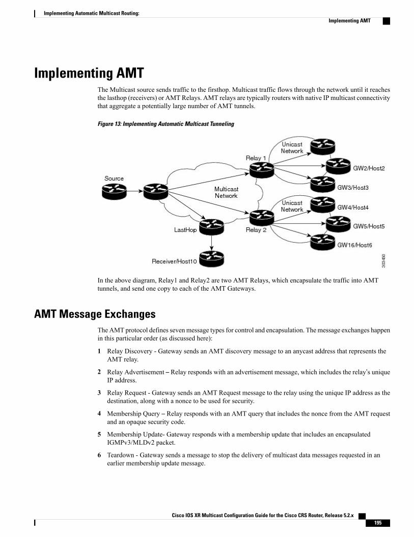
Implementing AMTThe Multicast source sends traffic to the firsthop. Multicast traffic flows through the network until it reachesthe lasthop (receivers) or AMTRelays. AMT relays are typically routers with native IP multicast connectivitythat aggregate a potentially large number of AMT tunnels.
Figure 13: Implementing Automatic Multicast Tunneling
In the above diagram, Relay1 and Relay2 are two AMT Relays, which encapsulate the traffic into AMTtunnels, and send one copy to each of the AMT Gateways.
AMT Message ExchangesThe AMT protocol defines sevenmessage types for control and encapsulation. Themessage exchanges happenin this particular order (as discussed here):
1 Relay Discovery - Gateway sends an AMT discovery message to an anycast address that represents theAMT relay.
2 Relay Advertisement – Relay responds with an advertisement message, which includes the relay’s uniqueIP address.
3 Relay Request - Gateway sends an AMT Request message to the relay using the unique IP address as thedestination, along with a nonce to be used for security.
4 Membership Query – Relay responds with an AMT query that includes the nonce from the AMT requestand an opaque security code.
5 Membership Update- Gateway responds with a membership update that includes an encapsulatedIGMPv3/MLDv2 packet.
6 Teardown - Gateway sends a message to stop the delivery of multicast data messages requested in anearlier membership update message.
Cisco IOS XR Multicast Configuration Guide for the Cisco CRS Router, Release 5.2.x 195
Implementing Automatic Multicast Routing:Implementing AMT
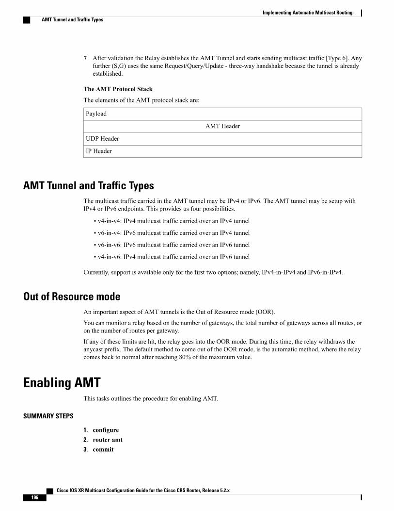
7 After validation the Relay establishes the AMT Tunnel and starts sending multicast traffic [Type 6]. Anyfurther (S,G) uses the same Request/Query/Update - three-way handshake because the tunnel is alreadyestablished.
The AMT Protocol Stack
The elements of the AMT protocol stack are:
Payload
AMT Header
UDP Header
IP Header
AMT Tunnel and Traffic TypesThe multicast traffic carried in the AMT tunnel may be IPv4 or IPv6. The AMT tunnel may be setup withIPv4 or IPv6 endpoints. This provides us four possibilities.
• v4-in-v4: IPv4 multicast traffic carried over an IPv4 tunnel
• v6-in-v4: IPv6 multicast traffic carried over an IPv4 tunnel
• v6-in-v6: IPv6 multicast traffic carried over an IPv6 tunnel
• v4-in-v6: IPv4 multicast traffic carried over an IPv6 tunnel
Currently, support is available only for the first two options; namely, IPv4-in-IPv4 and IPv6-in-IPv4.
Out of Resource modeAn important aspect of AMT tunnels is the Out of Resource mode (OOR).
You can monitor a relay based on the number of gateways, the total number of gateways across all routes, oron the number of routes per gateway.
If any of these limits are hit, the relay goes into the OOR mode. During this time, the relay withdraws theanycast prefix. The default method to come out of the OOR mode, is the automatic method, where the relaycomes back to normal after reaching 80% of the maximum value.
Enabling AMTThis tasks outlines the procedure for enabling AMT.
SUMMARY STEPS
1. configure2. router amt3. commit
Cisco IOS XR Multicast Configuration Guide for the Cisco CRS Router, Release 5.2.x196
Implementing Automatic Multicast Routing:AMT Tunnel and Traffic Types

DETAILED STEPS
PurposeCommand or Action
configureStep 1
Enters the AMT configuration mode.router amtStep 2
Example:RP/0/RP0/CPU0:router(config) # router amt
commitStep 3
Configuring AMTThis procedure describes the steps involved in configuring various AMT parameters.
The AMT commands used in this configuration procedure, are discussed in detail in the Cisco IOS XRMulticast Command Reference for the Cisco CRS Router.
.
SUMMARY STEPS
1. configure2. router amt3. relay ipv44. Use one of these commands:
• advertisement-address relay-address
• gateway gateway-address
• gateway-filter acl-name
• maximum-gateway value
• maximum route value
• mtu mtu-value
• ttl ttl-value
• tos tos-value
• qqic qqic-value
5. exit6. commit
Cisco IOS XR Multicast Configuration Guide for the Cisco CRS Router, Release 5.2.x 197
Implementing Automatic Multicast Routing:Configuring AMT
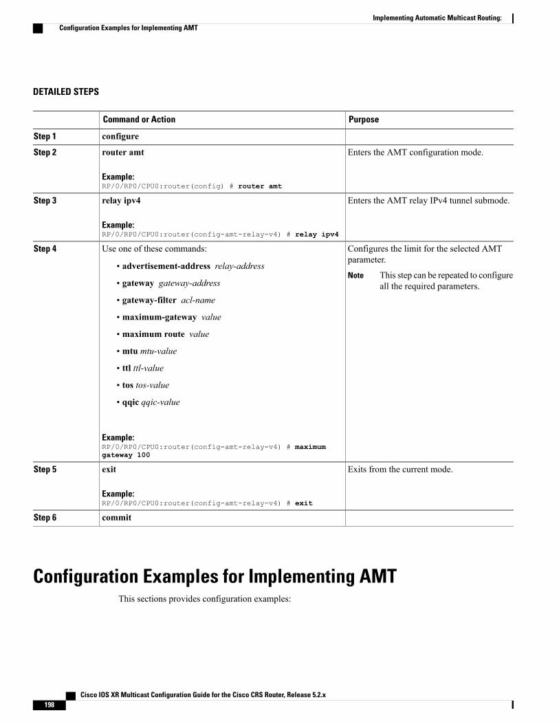
DETAILED STEPS
PurposeCommand or Action
configureStep 1
Enters the AMT configuration mode.router amt
Example:RP/0/RP0/CPU0:router(config) # router amt
Step 2
Enters the AMT relay IPv4 tunnel submode.relay ipv4
Example:RP/0/RP0/CPU0:router(config-amt-relay-v4) # relay ipv4
Step 3
Configures the limit for the selected AMTparameter.
Use one of these commands:Step 4
• advertisement-address relay-addressThis step can be repeated to configureall the required parameters.
Note• gateway gateway-address
• gateway-filter acl-name
• maximum-gateway value
• maximum route value
• mtu mtu-value
• ttl ttl-value
• tos tos-value
• qqic qqic-value
Example:RP/0/RP0/CPU0:router(config-amt-relay-v4) # maximumgateway 100
Exits from the current mode.exit
Example:RP/0/RP0/CPU0:router(config-amt-relay-v4) # exit
Step 5
commitStep 6
Configuration Examples for Implementing AMTThis sections provides configuration examples:
Cisco IOS XR Multicast Configuration Guide for the Cisco CRS Router, Release 5.2.x198
Implementing Automatic Multicast Routing:Configuration Examples for Implementing AMT

Enabling AMT: ExampleThis example shows how to enable AMT on the router.config
router amtend
!
AMT Maximum Gateway Configuration: ExampleThis example shows how to set the maximum gateway value at 100 for the AMT tunnels:configrouter amtrelay ipv4maximum gateway 100end!
AMT MTU Configuration: ExampleThis example shows how to set the MTU value (Maximum Transmission Units) for an AMT relay:configrouter amtrelay ipv4mtu 500end!
AMT TOS Configuration: ExampleThis example shows how to set the TOS value (Type of Service) for an AMT relay:configrouter amtrelay ipv4tos 100end!
Cisco IOS XR Multicast Configuration Guide for the Cisco CRS Router, Release 5.2.x 199
Implementing Automatic Multicast Routing:Enabling AMT: Example

Cisco IOS XR Multicast Configuration Guide for the Cisco CRS Router, Release 5.2.x200
Implementing Automatic Multicast Routing:AMT TOS Configuration: Example