cisco embedded service 2020 series switches hardware … · 5 cisco embedded service 2020 series...
TRANSCRIPT
Cisco Embedded Service 2020 Series Switches Hardware Technical Guide
Models: ESS-2020-CON, ESS-2020-NCP, ESS-2020-16TC-CON, ESS-2020-16TC-NCP
Published March 2018
Revised February 2019This hardware technical guide provides a product description, specifications, and compliance information for the Cisco Embedded Service 2020 Series Switches.
ContentsThis guide is organized into the following sections:
• Overview, page 2
• Audience, page 2
• Main Board Layout and Dimensions, page 3
• Expansion Board Layout and Dimensions, page 7
• Interface Connectors, page 11
• LED Definitions, page 24
• Factory Default Feature, page 29
• Mechanical and Environmental Testing, page 27
• Factory Default Feature, page 29
• Overtemperature Detection, page 29
• Thermal Design Considerations, page 30
• Product Specifications, page 37
• Power Requirements, page 38
• SFP Support, page 40
• Regulatory Compliance and Safety Information, page 43
• Obtaining Documentation and Submitting a Service Request, page 43
Americas Headquarters:Cisco Systems, Inc., 170 West Tasman Drive, San Jose, CA 95134-1706 USA
Overview
OverviewThe Cisco ESS 2020 is an embedded Ethernet switch card family that conforms to the PC104 form factor board size. The compact design simplifies integration and offers system integrators the ability to use the Cisco ESS 2020 in a wide variety of applications. The Cisco ESS 2020 consists of a main board and an optional expansion board. Both the main board and the expansion board are available with Cisco-designed cooling plates, and are also available without the cooling plates for system integrators who want to design their own custom thermal solutions.
Table 1 provides the hardware product IDs and brief descriptions for the boards.
Note Refer to the Cisco ESS 2020 data sheet for a complete list of available product IDs.
Note When using the console connection, it is important to not press the break key too early during boot. You should only press the break key when the image begins to load (you will see pound signs). Failure to wait will not allow the break key to work.
AudienceThis guide is for system integrators who are integrating the Cisco ESS 2020 into a custom end product.
Table 1 Cisco ESS 2020 Models
Model Description Software Image
ESS-2020-CON Embedded Service Switch Main Board (with conduction cooling plate), 2GE (copper or fiber), 8FE, console
LAN Lite
Can upgrade to LAN Base
ESS-2020-NCP Embedded Service Switch Main Board (no cooling plate), 2GE (copper or fiber), 8FE, console
LAN Lite
Can upgrade to LAN Base
ESS-2020-16TC-CON Embedded Service Switch Expansion Board (with conduction cooling plate), 16FE
ESS-2020-16TC-NCP Embedded Service Switch Expansion Board (no cooling plate), 16FE
2Cisco Embedded Service 2020 Series Switches Hardware Technical Guide
OL-28824-01
Main Board Layout and Dimensions
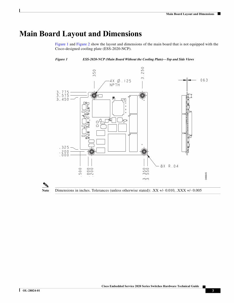
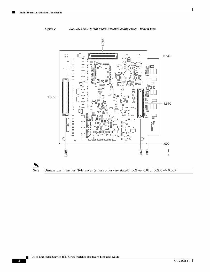
Main Board Layout and DimensionsFigure 1 and Figure 2 show the layout and dimensions of the main board that is not equipped with the Cisco-designed cooling plate (ESS-2020-NCP).
Figure 1 ESS-2020-NCP (Main Board Without the Cooling Plate)—Top and Side Views
Note Dimensions in inches. Tolerances (unless otherwise stated): .XX +/- 0.010, .XXX +/- 0.005
3466
45
3Cisco Embedded Service 2020 Series Switches Hardware Technical Guide
OL-28824-01
Main Board Layout and Dimensions
Figure 2 ESS-2020-NCP (Main Board Without Cooling Plate)—Bottom View
Note Dimensions in inches. Tolerances (unless otherwise stated): .XX +/- 0.010, .XXX +/- 0.005
1.78
5
1.885
3.29
5
.260
.000
3.545
1.630
.000
3475
82
4Cisco Embedded Service 2020 Series Switches Hardware Technical Guide
OL-28824-01
Main Board Layout and Dimensions
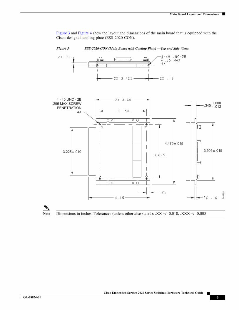
Figure 3 and Figure 4 show the layout and dimensions of the main board that is equipped with the Cisco-designed cooling plate (ESS-2020-CON).
Figure 3 ESS-2020-CON (Main Board with Cooling Plate) —Top and Side Views
Note Dimensions in inches. Tolerances (unless otherwise stated): .XX +/- 0.010, .XXX +/- 0.005
3467
02
4 - 40 UNC - 2B.295 MAX SCREW
PENETRATION4X
3.225 .010
4.475 .015
.345 - .012+.000
3.905 .015
5Cisco Embedded Service 2020 Series Switches Hardware Technical Guide
OL-28824-01
Main Board Layout and Dimensions
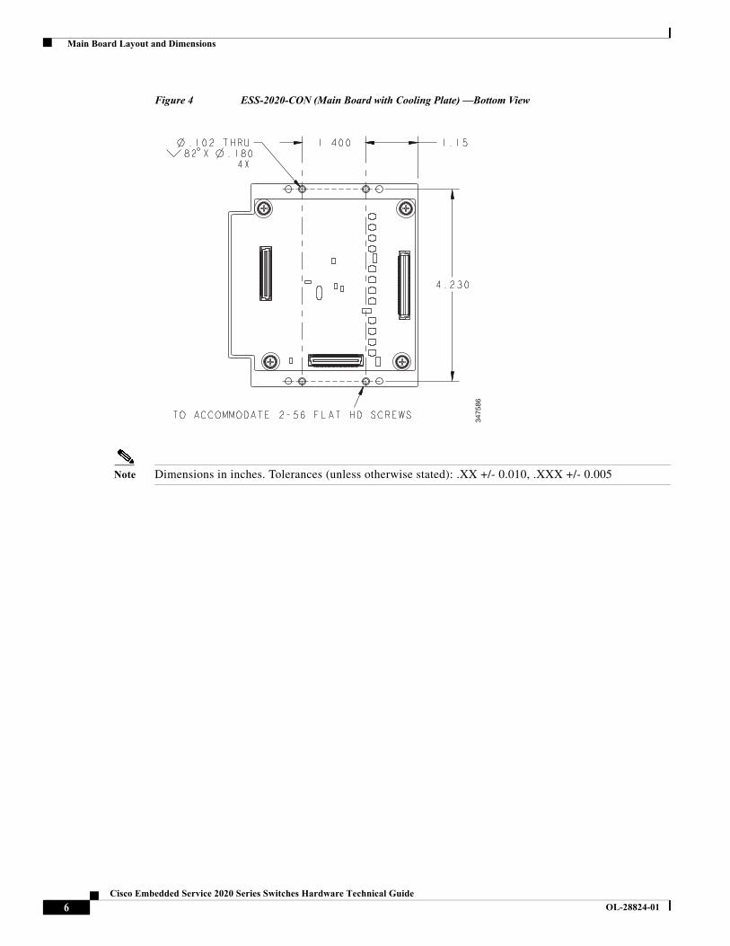
Figure 4 ESS-2020-CON (Main Board with Cooling Plate) —Bottom View
Note Dimensions in inches. Tolerances (unless otherwise stated): .XX +/- 0.010, .XXX +/- 0.00534
7586
6Cisco Embedded Service 2020 Series Switches Hardware Technical Guide
OL-28824-01
Expansion Board Layout and Dimensions
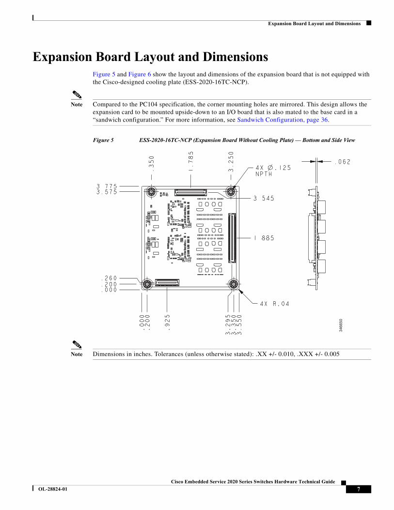
Expansion Board Layout and DimensionsFigure 5 and Figure 6 show the layout and dimensions of the expansion board that is not equipped with the Cisco-designed cooling plate (ESS-2020-16TC-NCP).
Note Compared to the PC104 specification, the corner mounting holes are mirrored. This design allows the expansion card to be mounted upside-down to an I/O board that is also mated to the base card in a “sandwich configuration.” For more information, see Sandwich Configuration, page 36.
Figure 5 ESS-2020-16TC-NCP (Expansion Board Without Cooling Plate) — Bottom and Side View
Note Dimensions in inches. Tolerances (unless otherwise stated): .XX +/- 0.010, .XXX +/- 0.005
3466
50
7Cisco Embedded Service 2020 Series Switches Hardware Technical Guide
OL-28824-01
Expansion Board Layout and Dimensions
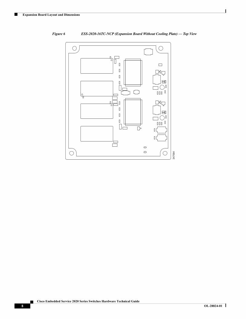
Figure 6 ESS-2020-16TC-NCP (Expansion Board Without Cooling Plate) — Top View
3475
84
8Cisco Embedded Service 2020 Series Switches Hardware Technical Guide
OL-28824-01
Expansion Board Layout and Dimensions
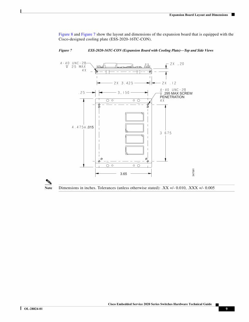
Figure 8 and Figure 7 show the layout and dimensions of the expansion board that is equipped with the Cisco-designed cooling plate (ESS-2020-16TC-CON).
Figure 7 ESS-2020-16TC-CON (Expansion Board with Cooling Plate)—Top and Side Views
Note Dimensions in inches. Tolerances (unless otherwise stated): .XX +/- 0.010, .XXX +/- 0.00534
7581
PENETRATION.295 MAX SCREW
3.65
.015
9Cisco Embedded Service 2020 Series Switches Hardware Technical Guide
OL-28824-01
Expansion Board Layout and Dimensions
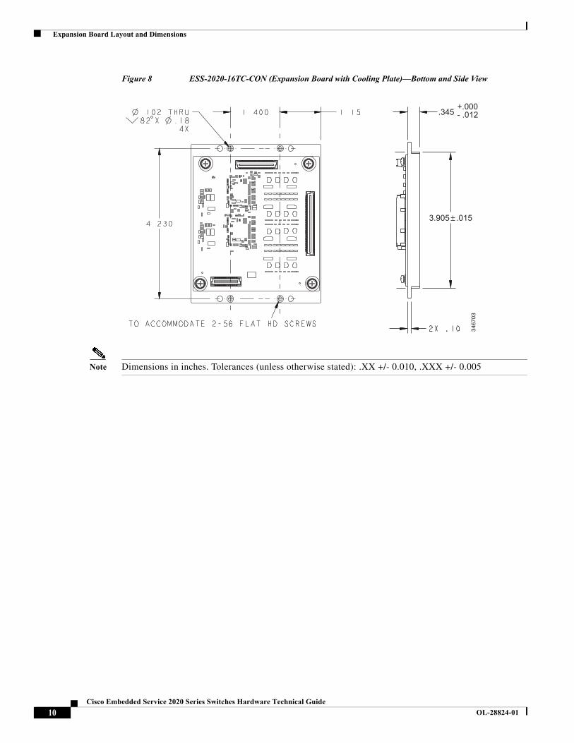
Figure 8 ESS-2020-16TC-CON (Expansion Board with Cooling Plate)—Bottom and Side View
Note Dimensions in inches. Tolerances (unless otherwise stated): .XX +/- 0.010, .XXX +/- 0.005
3467
03
.345 - .012+.000
3.905 .015
10Cisco Embedded Service 2020 Series Switches Hardware Technical Guide
OL-28824-01
Interface Connectors
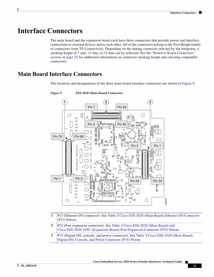
Interface ConnectorsThe main board and the expansion board each have three connectors that provide power and interface connections to external devices and to each other. All of the connectors belong to the Free Height family of connectors from TE Connectivity. Depending on the mating connector selected by the integrator, a stacking height of 7 mm, 11 mm, or 15 mm can be achieved. See the “Board to Board Connectors” section on page 23 for additional information on connector stacking height and selecting compatible connectors.
Main Board Interface Connectors
The locations and designations of the three main board interface connectors are shown in Figure 9.
Figure 9 ESS-2020 (Main Board) Connectors
1 P13 (Ethernet I/O connector). See Table 2 Cisco ESS-2020 (Main Board) Ethernet I/O Connector (P13) Pinout.
2 P22 (Port expansion connector). See Table 4 Cisco ESS-2020 (Main Board) and Cisco ESS-2020-16TC (Expansion Board) Port Expansion Connector (P22) Pinout.
3 P15 (Digital I/O, console, and power connector). See Table 3 Cisco ESS-2020 (Main Board) Digital I/O, Console, and Power Connector (P15) Pinout.
2 31
3466
48
Pin 1 Pin 59
Pin 2 Pin 60
Pin 2 Pin 1
Pin 60 Pin 59
Pin 79 Pin 80
Pin 1 Pin 2
11Cisco Embedded Service 2020 Series Switches Hardware Technical Guide
OL-28824-01
Interface Connectors
ESS-2020 (Main Board) Ethernet I/O Connector (P13)
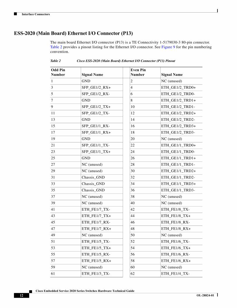
The main board Ethernet I/O connector (P13) is a TE Connectivity 1-5179030-3 80-pin connector. Table 2 provides a pinout listing for the Ethernet I/O connector. See Figure 9 for the pin numbering convention.
Table 2 Cisco ESS-2020 (Main Board) Ethernet I/O Connector (P13) Pinout
Odd Pin Number Signal Name
Even Pin Number Signal Name
1 GND 2 NC (unused)
3 SFP_GE1/2_RX+ 4 ETH_GE1/2_TRD0+
5 SFP_GE1/2_RX- 6 ETH_GE1/2_TRD0-
7 GND 8 ETH_GE1/2_TRD1+
9 SFP_GE1/2_TX+ 10 ETH_GE1/2_TRD1-
11 SFP_GE1/2_TX- 12 ETH_GE1/2_TRD2+
13 GND 14 ETH_GE1/2_TRD2-
15 SFP_GE1/1_RX- 16 ETH_GE1/2_TRD3+
17 SFP_GE1/1_RX+ 18 ETH_GE1/2_TRD3-
19 GND 20 NC (unused)
21 SFP_GE1/1_TX- 22 ETH_GE1/1_TRD0+
23 SFP_GE1/1_TX+ 24 ETH_GE1/1_TRD0-
25 GND 26 ETH_GE1/1_TRD1+
27 NC (unused) 28 ETH_GE1/1_TRD1-
29 NC (unused) 30 ETH_GE1/1_TRD2+
31 Chassis_GND 32 ETH_GE1/1_TRD2-
33 Chassis_GND 34 ETH_GE1/1_TRD3+
35 Chassis_GND 36 ETH_GE1/1_TRD3-
37 NC (unused) 38 NC (unused)
39 NC (unused) 40 NC (unused)
41 ETH_FE1/7_TX- 42 ETH_FE1/8_TX-
43 ETH_FE1/7_TX+ 44 ETH_FE1/8_TX+
45 ETH_FE1/7_RX- 46 ETH_FE1/8_RX-
47 ETH_FE1/7_RX+ 48 ETH_FE1/8_RX+
49 NC (unused) 50 NC (unused)
51 ETH_FE1/5_TX- 52 ETH_FE1/6_TX-
53 ETH_FE1/5_TX+ 54 ETH_FE1/6_TX+
55 ETH_FE1/5_RX- 56 ETH_FE1/6_RX-
57 ETH_FE1/5_RX+ 58 ETH_FE1/6_RX+
59 NC (unused) 60 NC (unused)
61 ETH_FE1/3_TX- 62 ETH_FE1/4_TX-
12Cisco Embedded Service 2020 Series Switches Hardware Technical Guide
OL-28824-01
Interface Connectors
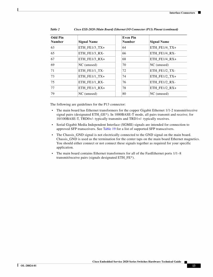
The following are guidelines for the P13 connector:
• The main board has Ethernet transformers for the copper Gigabit Ethernet 1/1-2 transmit/receive signal pairs (designated ETH_GE*). In 1000BASE-T mode, all pairs transmit and receive; for 10/100BASE-T, TRD0+/- typically transmits and TRD1+/- typically receives.
• Serial Gigabit Media Independent Interface (SGMII) signals are intended for connection to approved SFP transceivers. See Table 19 for a list of supported SFP transceivers.
• The Chassis_GND signal is not electrically connected to the GND signal on the main board. Chassis_GND is used as the termination for the center taps on the main board Ethernet magnetics. You should either connect or not connect these signals together as required for your specific application.
• The main board contains Ethernet transformers for all of the FastEthernet ports 1/1–8 transmit/receive pairs (signals designated ETH_FE*).
63 ETH_FE1/3_TX+ 64 ETH_FE1/4_TX+
65 ETH_FE1/3_RX- 66 ETH_FE1/4_RX-
67 ETH_FE1/3_RX+ 68 ETH_FE1/4_RX+
69 NC (unused) 70 NC (unused)
71 ETH_FE1/1_TX- 72 ETH_FE1/2_TX-
73 ETH_FE1/1_TX+ 74 ETH_FE1/2_TX+
75 ETH_FE1/1_RX- 76 ETH_FE1/2_RX-
77 ETH_FE1/1_RX+ 78 ETH_FE1/2_RX+
79 NC (unused) 80 NC (unused)
Table 2 Cisco ESS-2020 (Main Board) Ethernet I/O Connector (P13) Pinout (continued)
Odd Pin Number Signal Name
Even Pin Number Signal Name
13Cisco Embedded Service 2020 Series Switches Hardware Technical Guide
OL-28824-01
Interface Connectors
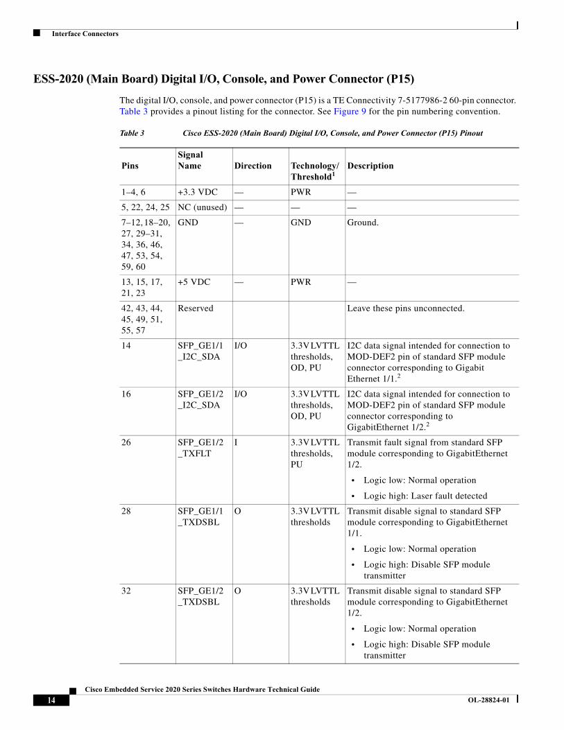
ESS-2020 (Main Board) Digital I/O, Console, and Power Connector (P15)
The digital I/O, console, and power connector (P15) is a TE Connectivity 7-5177986-2 60-pin connector. Table 3 provides a pinout listing for the connector. See Figure 9 for the pin numbering convention.
Table 3 Cisco ESS-2020 (Main Board) Digital I/O, Console, and Power Connector (P15) Pinout
PinsSignal Name Direction Technology/
Threshold1Description
1–4, 6 +3.3 VDC — PWR —
5, 22, 24, 25 NC (unused) — — —
7–12, 18–20, 27, 29–31, 34, 36, 46, 47, 53, 54, 59, 60
GND — GND Ground.
13, 15, 17, 21, 23
+5 VDC — PWR —
42, 43, 44, 45, 49, 51, 55, 57
Reserved Leave these pins unconnected.
14 SFP_GE1/1_I2C_SDA
I/O 3.3V LVTTL thresholds, OD, PU
I2C data signal intended for connection to MOD-DEF2 pin of standard SFP module connector corresponding to Gigabit Ethernet 1/1.2
16 SFP_GE1/2_I2C_SDA
I/O 3.3V LVTTL thresholds, OD, PU
I2C data signal intended for connection to MOD-DEF2 pin of standard SFP module connector corresponding to GigabitEthernet 1/2.2
26 SFP_GE1/2_TXFLT
I 3.3V LVTTL thresholds, PU
Transmit fault signal from standard SFP module corresponding to GigabitEthernet 1/2.
• Logic low: Normal operation
• Logic high: Laser fault detected
28 SFP_GE1/1_TXDSBL
O 3.3V LVTTL thresholds
Transmit disable signal to standard SFP module corresponding to GigabitEthernet 1/1.
• Logic low: Normal operation
• Logic high: Disable SFP module transmitter
32 SFP_GE1/2_TXDSBL
O 3.3V LVTTL thresholds
Transmit disable signal to standard SFP module corresponding to GigabitEthernet 1/2.
• Logic low: Normal operation
• Logic high: Disable SFP module transmitter
14Cisco Embedded Service 2020 Series Switches Hardware Technical Guide
OL-28824-01
Interface Connectors
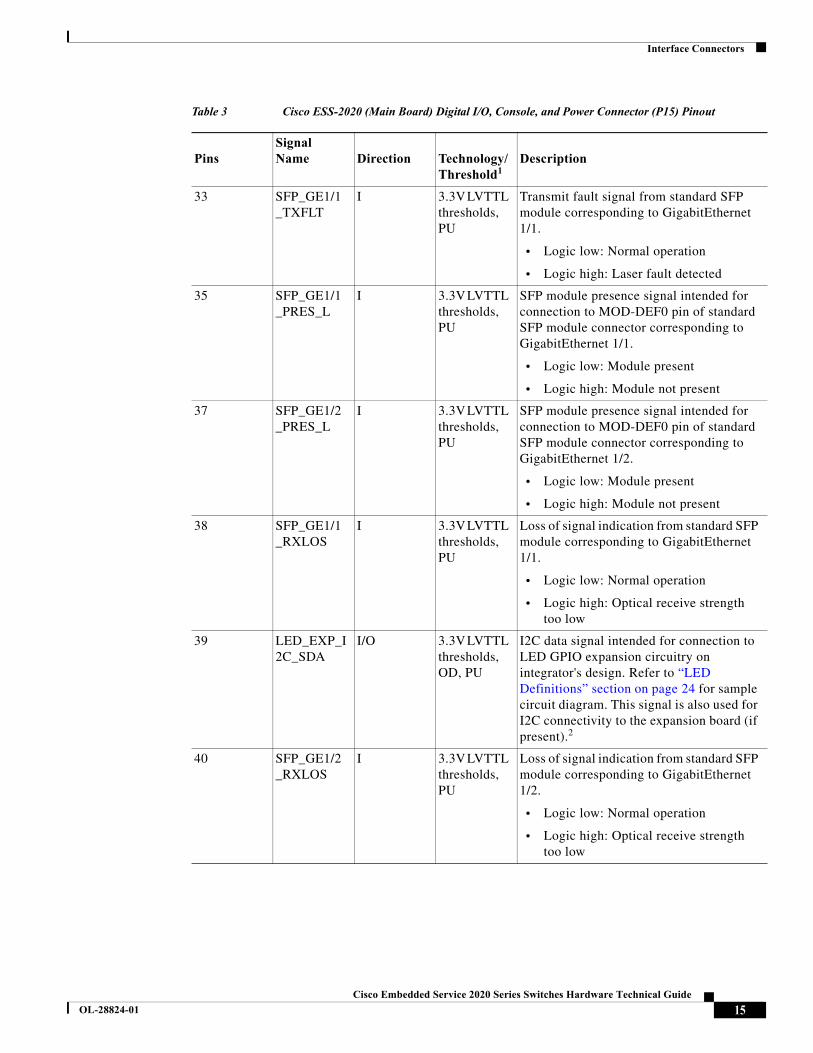
33 SFP_GE1/1_TXFLT
I 3.3V LVTTL thresholds, PU
Transmit fault signal from standard SFP module corresponding to GigabitEthernet 1/1.
• Logic low: Normal operation
• Logic high: Laser fault detected
35 SFP_GE1/1_PRES_L
I 3.3V LVTTL thresholds, PU
SFP module presence signal intended for connection to MOD-DEF0 pin of standard SFP module connector corresponding to GigabitEthernet 1/1.
• Logic low: Module present
• Logic high: Module not present
37 SFP_GE1/2_PRES_L
I 3.3V LVTTL thresholds, PU
SFP module presence signal intended for connection to MOD-DEF0 pin of standard SFP module connector corresponding to GigabitEthernet 1/2.
• Logic low: Module present
• Logic high: Module not present
38 SFP_GE1/1_RXLOS
I 3.3V LVTTL thresholds, PU
Loss of signal indication from standard SFP module corresponding to GigabitEthernet 1/1.
• Logic low: Normal operation
• Logic high: Optical receive strength too low
39 LED_EXP_I2C_SDA
I/O 3.3V LVTTL thresholds, OD, PU
I2C data signal intended for connection to LED GPIO expansion circuitry on integrator's design. Refer to “LED Definitions” section on page 24 for sample circuit diagram. This signal is also used for I2C connectivity to the expansion board (if present).2
40 SFP_GE1/2_RXLOS
I 3.3V LVTTL thresholds, PU
Loss of signal indication from standard SFP module corresponding to GigabitEthernet 1/2.
• Logic low: Normal operation
• Logic high: Optical receive strength too low
Table 3 Cisco ESS-2020 (Main Board) Digital I/O, Console, and Power Connector (P15) Pinout
PinsSignal Name Direction Technology/
Threshold1Description
15Cisco Embedded Service 2020 Series Switches Hardware Technical Guide
OL-28824-01
Interface Connectors
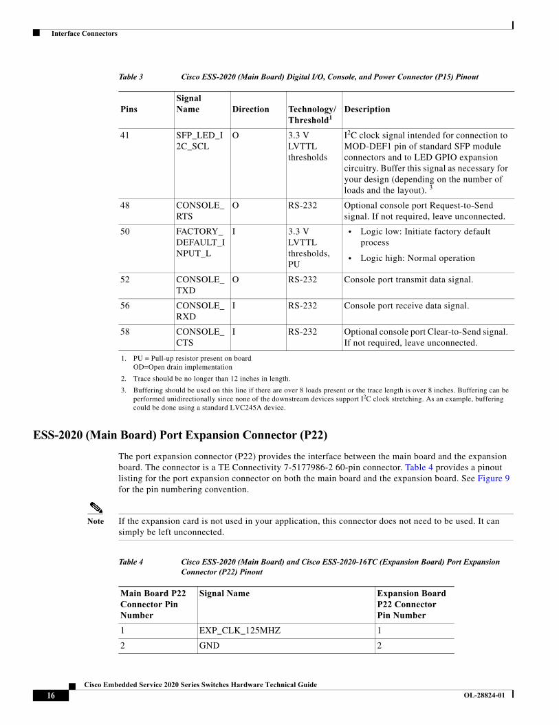
ESS-2020 (Main Board) Port Expansion Connector (P22)
The port expansion connector (P22) provides the interface between the main board and the expansion board. The connector is a TE Connectivity 7-5177986-2 60-pin connector. Table 4 provides a pinout listing for the port expansion connector on both the main board and the expansion board. See Figure 9 for the pin numbering convention.
Note If the expansion card is not used in your application, this connector does not need to be used. It can simply be left unconnected.
41 SFP_LED_I2C_SCL
O 3.3 V LVTTL thresholds
I2C clock signal intended for connection to MOD-DEF1 pin of standard SFP module connectors and to LED GPIO expansion circuitry. Buffer this signal as necessary for your design (depending on the number of loads and the layout). 3
48 CONSOLE_RTS
O RS-232 Optional console port Request-to-Send signal. If not required, leave unconnected.
50 FACTORY_DEFAULT_INPUT_L
I 3.3 V LVTTL thresholds, PU
• Logic low: Initiate factory default process
• Logic high: Normal operation
52 CONSOLE_TXD
O RS-232 Console port transmit data signal.
56 CONSOLE_RXD
I RS-232 Console port receive data signal.
58 CONSOLE_CTS
I RS-232 Optional console port Clear-to-Send signal. If not required, leave unconnected.
1. PU = Pull-up resistor present on boardOD=Open drain implementation
2. Trace should be no longer than 12 inches in length.
3. Buffering should be used on this line if there are over 8 loads present or the trace length is over 8 inches. Buffering can be performed unidirectionally since none of the downstream devices support I2C clock stretching. As an example, buffering could be done using a standard LVC245A device.
Table 3 Cisco ESS-2020 (Main Board) Digital I/O, Console, and Power Connector (P15) Pinout
PinsSignal Name Direction Technology/
Threshold1Description
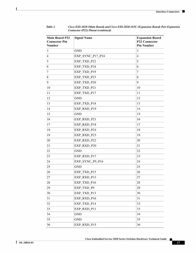
Table 4 Cisco ESS-2020 (Main Board) and Cisco ESS-2020-16TC (Expansion Board) Port Expansion Connector (P22) Pinout
Main Board P22 Connector Pin Number
Signal Name Expansion Board P22 Connector Pin Number
1 EXP_CLK_125MHZ 1
2 GND 2
16Cisco Embedded Service 2020 Series Switches Hardware Technical Guide
OL-28824-01
Interface Connectors
3 GND 3
4 EXP_SYNC_P17_P24 4
5 EXP_TXD_P22 5
6 EXP_TXD_P24 6
7 EXP_TXD_P19 7
8 EXP_TXD_P23 8
9 EXP_TXD_P20 9
10 EXP_TXD_P21 10
11 EXP_TXD_P17 11
12 GND 12
13 EXP_TXD_P18 13
14 EXP_RXD_P19 14
15 GND 15
16 EXP_RXD_P21 16
17 EXP_RXD_P18 17
18 EXP_RXD_P24 18
19 EXP_RXD_P23 19
20 EXP_RXD_P22 20
21 EXP_RXD_P20 21
22 GND 22
23 EXP_RXD_P17 23
24 EXP_SYNC_P9_P16 24
25 GND 25
26 EXP_TXD_P15 26
27 EXP_RXD_P13 27
28 EXP_TXD_P16 28
29 EXP_TXD_P9 29
30 EXP_TXD_P13 30
31 EXP_RXD_P16 31
32 EXP_TXD_P14 32
33 EXP_RXD_P11 33
34 GND 34
35 GND 35
36 EXP_RXD_P15 36
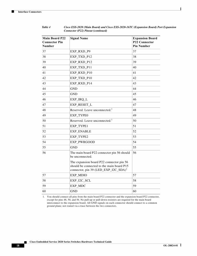
Table 4 Cisco ESS-2020 (Main Board) and Cisco ESS-2020-16TC (Expansion Board) Port Expansion Connector (P22) Pinout (continued)
Main Board P22 Connector Pin Number
Signal Name Expansion Board P22 Connector Pin Number
17Cisco Embedded Service 2020 Series Switches Hardware Technical Guide
OL-28824-01
Interface Connectors
37 EXP_RXD_P9 37
38 EXP_TXD_P12 38
39 EXP_RXD_P12 39
40 EXP_TXD_P11 40
41 EXP_RXD_P10 41
42 EXP_TXD_P10 42
43 EXP_RXD_P14 43
44 GND 44
45 GND 45
46 EXP_IRQ_L 46
47 EXP_RESET_L 47
48 Reserved. Leave unconnected.1 48
49 EXP_TYPE0 49
50 Reserved. Leave unconnected.1 50
51 EXP_TYPE1 51
52 EXP_ENABLE 52
53 EXP_TYPE2 53
54 EXP_PWRGOOD 54
55 GND 55
56 The main board P22 connector pin 56 should be unconnected.
The expansion board P22 connector pin 56 should be connected to the main board P15 connector, pin 39 (LED_EXP_I2C_SDA)1
56
57 EXP_MDIO 57
58 EXP_I2C_SCL 58
59 EXP_MDC 59
60 GND 60
1. You should connect all pins from the main board P22 connector and the expansion board P22 connector, except for pins 48, 50, and 56. No pull-up or pull-down resistors are required for the main board interconnect to the expansion board. All GND signals on each connector should connect to a common ground plane; not routed via a trace between the two connectors.
Table 4 Cisco ESS-2020 (Main Board) and Cisco ESS-2020-16TC (Expansion Board) Port Expansion Connector (P22) Pinout (continued)
Main Board P22 Connector Pin Number
Signal Name Expansion Board P22 Connector Pin Number
18Cisco Embedded Service 2020 Series Switches Hardware Technical Guide
OL-28824-01
Interface Connectors
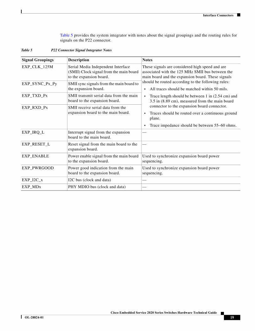
Table 5 provides the system integrator with notes about the signal groupings and the routing rules for signals on the P22 connector.
Table 5 P22 Connector Signal Integrator Notes
Signal Groupings Description Notes
EXP_CLK_125M Serial Media Independent Interface (SMII) Clock signal from the main board to the expansion board.
These signals are considered high speed and are associated with the 125 MHz SMII bus between the main board and the expansion board. These signals should be routed according to the following rules:
• All traces should be matched within 50 mils.
• Trace length should be between 1 in (2.54 cm) and 3.5 in (8.89 cm), measured from the main board connector to the expansion board connector.
• Traces should be routed over a continuous ground plane.
• Trace impedance should be between 55–60 ohms.
EXP_SYNC_Px_Py SMII sync signals from the main board to the expansion board.
EXP_TXD_Px SMII transmit serial data from the main board to the expansion board.
EXP_RXD_Px SMII receive serial data from the expansion board to the main board.
EXP_IRQ_L Interrupt signal from the expansion board to the main board.
—
EXP_RESET_L Reset signal from the main board to the expansion board.
—
EXP_ENABLE Power enable signal from the main board to the expansion board.
Used to synchronize expansion board power sequencing.
EXP_PWRGOOD Power good indication from the main board to the expansion board.
Used to synchronize expansion board power sequencing.
EXP_I2C_x I2C bus (clock and data) —
EXP_MDx PHY MDIO bus (clock and data) —
19Cisco Embedded Service 2020 Series Switches Hardware Technical Guide
OL-28824-01
Interface Connectors
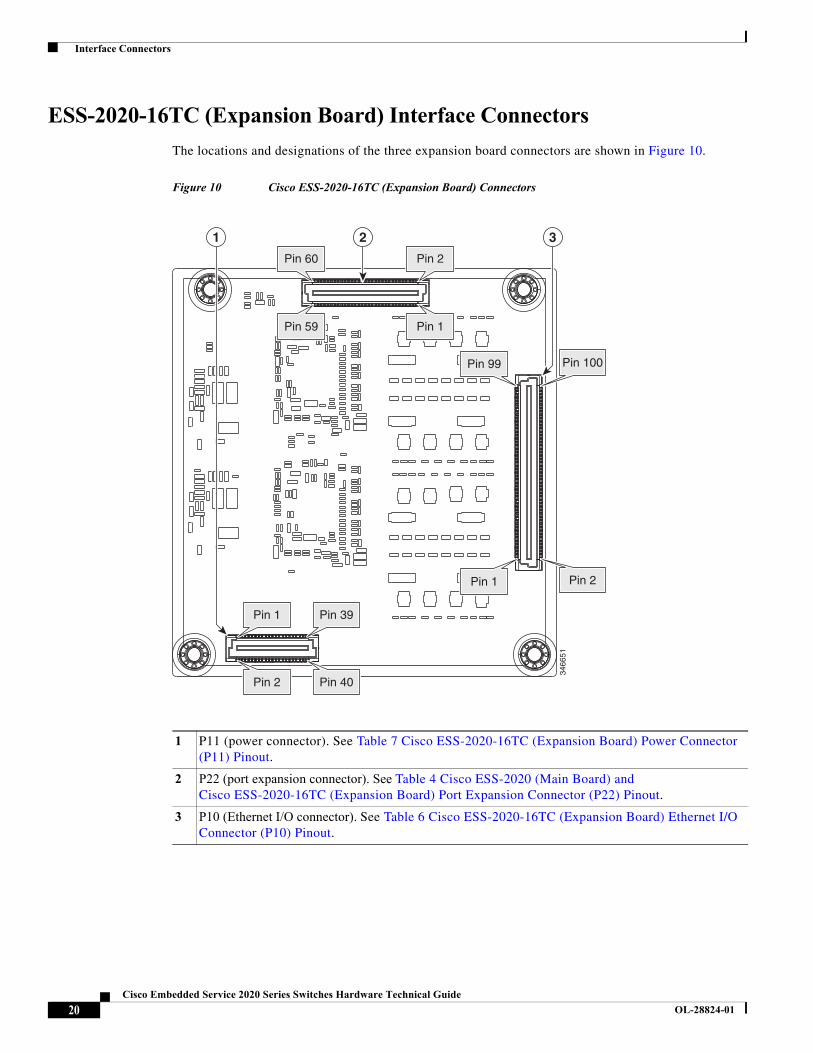
ESS-2020-16TC (Expansion Board) Interface Connectors
The locations and designations of the three expansion board connectors are shown in Figure 10.
Figure 10 Cisco ESS-2020-16TC (Expansion Board) Connectors
1 P11 (power connector). See Table 7 Cisco ESS-2020-16TC (Expansion Board) Power Connector (P11) Pinout.
2 P22 (port expansion connector). See Table 4 Cisco ESS-2020 (Main Board) and Cisco ESS-2020-16TC (Expansion Board) Port Expansion Connector (P22) Pinout.
3 P10 (Ethernet I/O connector). See Table 6 Cisco ESS-2020-16TC (Expansion Board) Ethernet I/O Connector (P10) Pinout.
2 31
3466
51
Pin 60 Pin 2
Pin 59 Pin 1
Pin 99 Pin 100
Pin 1 Pin 2
Pin 39
Pin 40
Pin 1
Pin 2
20Cisco Embedded Service 2020 Series Switches Hardware Technical Guide
OL-28824-01
Interface Connectors
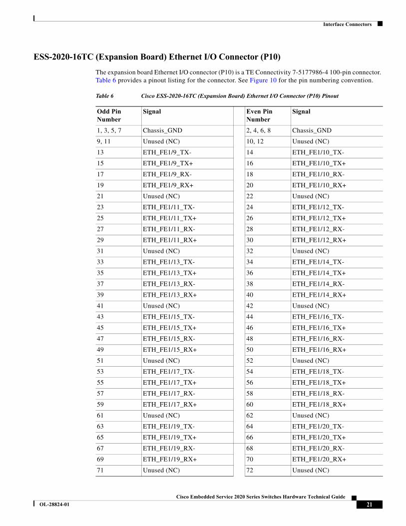
ESS-2020-16TC (Expansion Board) Ethernet I/O Connector (P10)
The expansion board Ethernet I/O connector (P10) is a TE Connectivity 7-5177986-4 100-pin connector. Table 6 provides a pinout listing for the connector. See Figure 10 for the pin numbering convention.
Table 6 Cisco ESS-2020-16TC (Expansion Board) Ethernet I/O Connector (P10) Pinout
Odd Pin Number
Signal Even Pin Number
Signal
1, 3, 5, 7 Chassis_GND 2, 4, 6, 8 Chassis_GND
9, 11 Unused (NC) 10, 12 Unused (NC)
13 ETH_FE1/9_TX- 14 ETH_FE1/10_TX-
15 ETH_FE1/9_TX+ 16 ETH_FE1/10_TX+
17 ETH_FE1/9_RX- 18 ETH_FE1/10_RX-
19 ETH_FE1/9_RX+ 20 ETH_FE1/10_RX+
21 Unused (NC) 22 Unused (NC)
23 ETH_FE1/11_TX- 24 ETH_FE1/12_TX-
25 ETH_FE1/11_TX+ 26 ETH_FE1/12_TX+
27 ETH_FE1/11_RX- 28 ETH_FE1/12_RX-
29 ETH_FE1/11_RX+ 30 ETH_FE1/12_RX+
31 Unused (NC) 32 Unused (NC)
33 ETH_FE1/13_TX- 34 ETH_FE1/14_TX-
35 ETH_FE1/13_TX+ 36 ETH_FE1/14_TX+
37 ETH_FE1/13_RX- 38 ETH_FE1/14_RX-
39 ETH_FE1/13_RX+ 40 ETH_FE1/14_RX+
41 Unused (NC) 42 Unused (NC)
43 ETH_FE1/15_TX- 44 ETH_FE1/16_TX-
45 ETH_FE1/15_TX+ 46 ETH_FE1/16_TX+
47 ETH_FE1/15_RX- 48 ETH_FE1/16_RX-
49 ETH_FE1/15_RX+ 50 ETH_FE1/16_RX+
51 Unused (NC) 52 Unused (NC)
53 ETH_FE1/17_TX- 54 ETH_FE1/18_TX-
55 ETH_FE1/17_TX+ 56 ETH_FE1/18_TX+
57 ETH_FE1/17_RX- 58 ETH_FE1/18_RX-
59 ETH_FE1/17_RX+ 60 ETH_FE1/18_RX+
61 Unused (NC) 62 Unused (NC)
63 ETH_FE1/19_TX- 64 ETH_FE1/20_TX-
65 ETH_FE1/19_TX+ 66 ETH_FE1/20_TX+
67 ETH_FE1/19_RX- 68 ETH_FE1/20_RX-
69 ETH_FE1/19_RX+ 70 ETH_FE1/20_RX+
71 Unused (NC) 72 Unused (NC)
21Cisco Embedded Service 2020 Series Switches Hardware Technical Guide
OL-28824-01
Interface Connectors
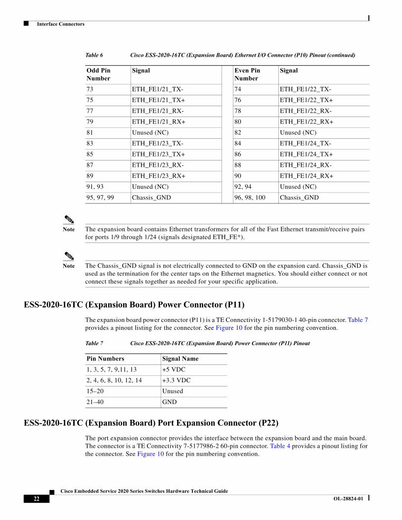
Note The expansion board contains Ethernet transformers for all of the Fast Ethernet transmit/receive pairs for ports 1/9 through 1/24 (signals designated ETH_FE*).
Note The Chassis_GND signal is not electrically connected to GND on the expansion card. Chassis_GND is used as the termination for the center taps on the Ethernet magnetics. You should either connect or not connect these signals together as needed for your specific application.
ESS-2020-16TC (Expansion Board) Power Connector (P11)
The expansion board power connector (P11) is a TE Connectivity 1-5179030-1 40-pin connector. Table 7 provides a pinout listing for the connector. See Figure 10 for the pin numbering convention.
ESS-2020-16TC (Expansion Board) Port Expansion Connector (P22)
The port expansion connector provides the interface between the expansion board and the main board. The connector is a TE Connectivity 7-5177986-2 60-pin connector. Table 4 provides a pinout listing for the connector. See Figure 10 for the pin numbering convention.
73 ETH_FE1/21_TX- 74 ETH_FE1/22_TX-
75 ETH_FE1/21_TX+ 76 ETH_FE1/22_TX+
77 ETH_FE1/21_RX- 78 ETH_FE1/22_RX-
79 ETH_FE1/21_RX+ 80 ETH_FE1/22_RX+
81 Unused (NC) 82 Unused (NC)
83 ETH_FE1/23_TX- 84 ETH_FE1/24_TX-
85 ETH_FE1/23_TX+ 86 ETH_FE1/24_TX+
87 ETH_FE1/23_RX- 88 ETH_FE1/24_RX-
89 ETH_FE1/23_RX+ 90 ETH_FE1/24_RX+
91, 93 Unused (NC) 92, 94 Unused (NC)
95, 97, 99 Chassis_GND 96, 98, 100 Chassis_GND
Table 6 Cisco ESS-2020-16TC (Expansion Board) Ethernet I/O Connector (P10) Pinout (continued)
Odd Pin Number
Signal Even Pin Number
Signal
Table 7 Cisco ESS-2020-16TC (Expansion Board) Power Connector (P11) Pinout
Pin Numbers Signal Name
1, 3, 5, 7, 9,11, 13 +5 VDC
2, 4, 6, 8, 10, 12, 14 +3.3 VDC
15–20 Unused
21–40 GND
22Cisco Embedded Service 2020 Series Switches Hardware Technical Guide
OL-28824-01
Interface Connectors
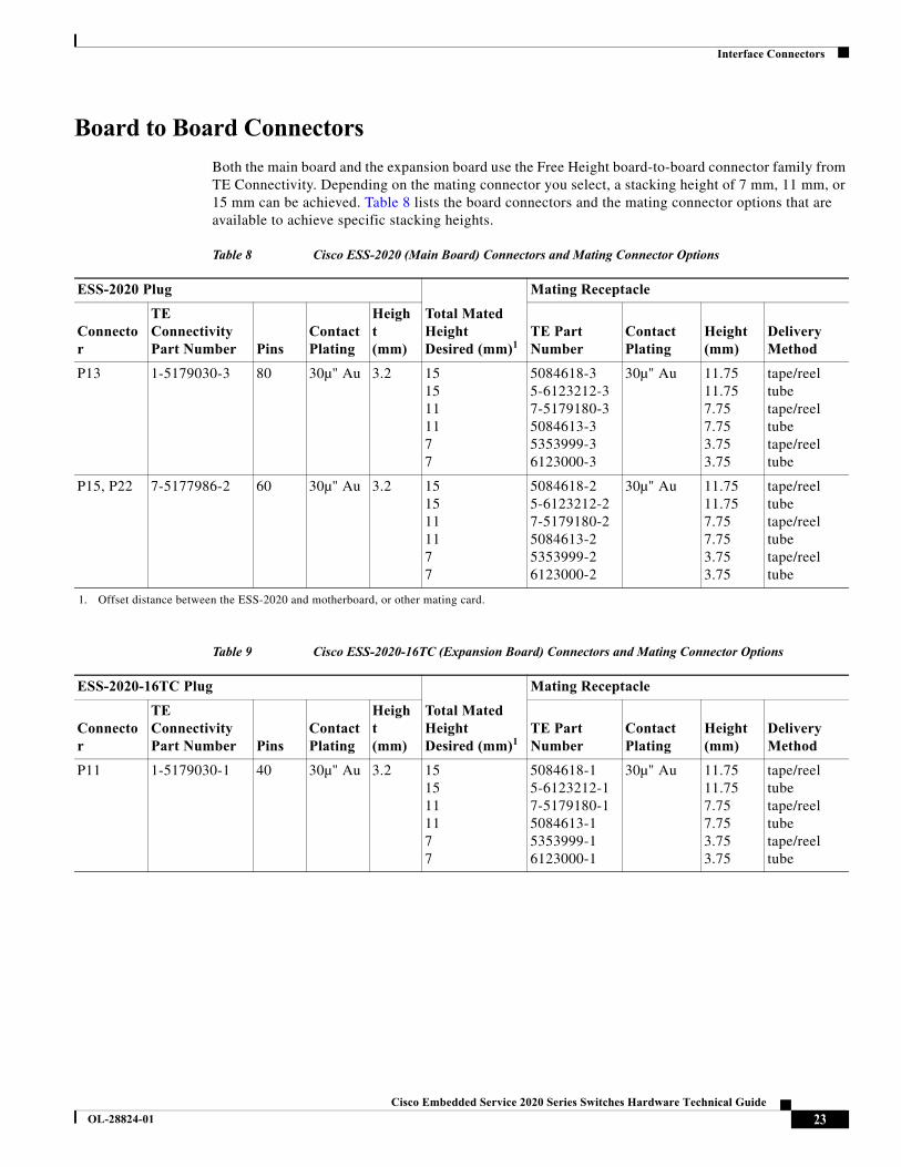
Board to Board Connectors
Both the main board and the expansion board use the Free Height board-to-board connector family from TE Connectivity. Depending on the mating connector you select, a stacking height of 7 mm, 11 mm, or 15 mm can be achieved. Table 8 lists the board connectors and the mating connector options that are available to achieve specific stacking heights.
Table 8 Cisco ESS-2020 (Main Board) Connectors and Mating Connector Options
ESS-2020 Plug
Total Mated Height Desired (mm)1
1. Offset distance between the ESS-2020 and motherboard, or other mating card.
Mating Receptacle
Connector
TE Connectivity Part Number Pins
Contact Plating
Height(mm)
TE Part Number
Contact Plating
Height(mm)
Delivery Method
P13 1-5179030-3 80 30µ" Au 3.2 1515111177
5084618-35-6123212-37-5179180-35084613-35353999-36123000-3
30µ" Au 11.7511.757.757.753.753.75
tape/reeltubetape/reeltubetape/reeltube
P15, P22 7-5177986-2 60 30µ" Au 3.2 1515111177
5084618-25-6123212-27-5179180-25084613-25353999-26123000-2
30µ" Au 11.7511.757.757.753.753.75
tape/reeltubetape/reeltubetape/reeltube
Table 9 Cisco ESS-2020-16TC (Expansion Board) Connectors and Mating Connector Options
ESS-2020-16TC Plug
Total Mated Height Desired (mm)1
Mating Receptacle
Connector
TE Connectivity Part Number Pins
Contact Plating
Height(mm)
TE Part Number
Contact Plating
Height(mm)
Delivery Method
P11 1-5179030-1 40 30µ" Au 3.2 1515111177
5084618-15-6123212-17-5179180-15084613-15353999-16123000-1
30µ" Au 11.7511.757.757.753.753.75
tape/reeltubetape/reeltubetape/reeltube
23Cisco Embedded Service 2020 Series Switches Hardware Technical Guide
OL-28824-01
LED Definitions
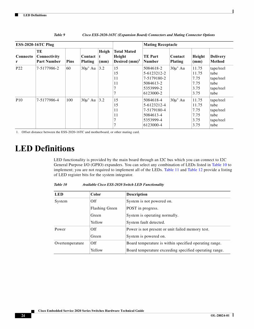
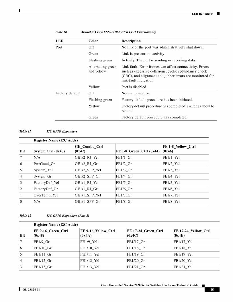
LED DefinitionsLED functionality is provided by the main board through an I2C bus which you can connect to I2C General Purpose I/O (GPIO) expanders. You can select any combination of LEDs listed in Table 10 to implement; you are not required to implement all of the LEDs. Table 11 and Table 12 provide a listing of LED register bits for the system integrator.
P22 7-5177986-2 60 30µ" Au 3.2 1515111177
5084618-25-6123212-27-5179180-25084613-25353999-26123000-2
30µ" Au 11.7511.757.757.753.753.75
tape/reeltubetape/reeltubetape/reeltube
P10 7-5177986-4 100 30µ" Au 3.2 1515111177
5084618-45-6123212-47-5179180-45084613-45353999-46123000-4
30µ" Au 11.7511.757.757.753.753.75
tape/reeltubetape/reeltubetape/reeltube
1. Offset distance between the ESS-2020-16TC and motherboard, or other mating card.
Table 9 Cisco ESS-2020-16TC (Expansion Board) Connectors and Mating Connector Options
ESS-2020-16TC Plug
Total Mated Height Desired (mm)1
Mating Receptacle
Connector
TE Connectivity Part Number Pins
Contact Plating
Height(mm)
TE Part Number
Contact Plating
Height(mm)
Delivery Method
Table 10 Available Cisco ESS-2020 Switch LED Functionality
LED Color Description
System Off
Flashing Green
Green
Yellow
System is not powered on.
POST in progress.
System is operating normally.
System fault detected.
Power Off
Green
Power is not present or unit failed memory test.
System is powered on.
Overtemperature Off
Yellow
Board temperature is within specified operating range.
Board temperature exceeding specified operating range.
24Cisco Embedded Service 2020 Series Switches Hardware Technical Guide
OL-28824-01
LED Definitions
Port Off
Green
Flashing green
Alternating green and yellow
Yellow
No link or the port was administratively shut down.
Link is present; no activity
Activity. The port is sending or receiving data.
Link fault. Error frames can affect connectivity. Errors such as excessive collisions, cyclic redundancy check (CRC), and alignment and jabber errors are monitored for link-fault indication.
Port is disabled
Factory default Off
Flashing green
Yellow
Green
Normal operation.
Factory default procedure has been initiated.
Factory default procedure has completed; switch is about to reboot.
Factory default procedure has completed.
Table 11 I2C GPIO Expanders
Register Name (I2C Addr)
Bit System Ctrl (0x40)GE_Combo_Ctrl (0x42) FE 1-8_Green_Ctrl (0x44)
FE 1-8_Yellow_Ctrl (0x46)
7 N/A GE1/2_RJ_Yel FE1/1_Gr FE1/1_Yel
6 PwrGood_Gr GE1/2_RJ_Gr FE1/2_Gr FE1/2_Yel
5 System_Yel GE1/2_SFP_Yel FE1/3_Gr FE1/3_Yel
4 System_Gr GE1/2_SFP_Gr FE1/4_Gr FE1/4_Yel
3 FactoryDef_Yel GE1/1_RJ_Yel FE1/5_Gr FE1/5_Yel
2 FactoryDef_Gr GE1/1_RJ_Gr1 FE1/6_Gr FE1/6_Yel
1 OverTemp_Yel GE1/1_SFP_Yel FE1/7_Gr FE1/7_Yel
0 N/A GE1/1_SFP_Gr FE1/8_Gr FE1/8_Yel
Table 12 I2C GPIO Expanders (Part 2)
Register Name (I2C Addr)
BitFE 9-16_Green_Ctrl (0x48)
FE 9-16_Yellow_Ctrl (0x4A)
FE 17-24_Green_Ctrl (0x4C)
FE 17-24_Yellow_Ctrl (0x4E)
7 FE1/9_Gr FE1/9_Yel FE1/17_Gr FE1/17_Yel
6 FE1/10_Gr FE1/10_Yel FE1/18_Gr FE1/18_Yel
5 FE1/11_Gr FE1/11_Yel FE1/19_Gr FE1/19_Yel
4 FE1/12_Gr FE1/12_Yel FE1/20_Gr FE1/20_Yel
3 FE1/13_Gr FE1/13_Yel FE1/21_Gr FE1/21_Yel
Table 10 Available Cisco ESS-2020 Switch LED Functionality
LED Color Description
25Cisco Embedded Service 2020 Series Switches Hardware Technical Guide
OL-28824-01
LED Definitions
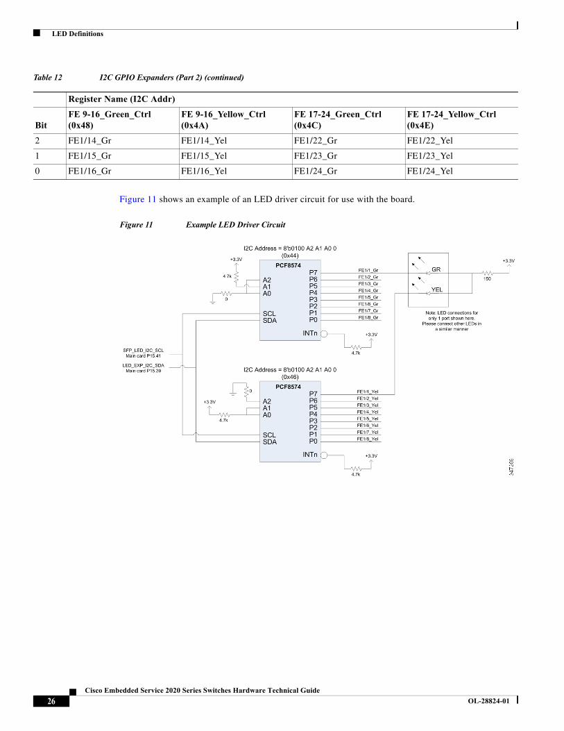
Figure 11 shows an example of an LED driver circuit for use with the board.
Figure 11 Example LED Driver Circuit
2 FE1/14_Gr FE1/14_Yel FE1/22_Gr FE1/22_Yel
1 FE1/15_Gr FE1/15_Yel FE1/23_Gr FE1/23_Yel
0 FE1/16_Gr FE1/16_Yel FE1/24_Gr FE1/24_Yel
Table 12 I2C GPIO Expanders (Part 2) (continued)
Register Name (I2C Addr)
BitFE 9-16_Green_Ctrl (0x48)
FE 9-16_Yellow_Ctrl (0x4A)
FE 17-24_Green_Ctrl (0x4C)
FE 17-24_Yellow_Ctrl (0x4E)
26Cisco Embedded Service 2020 Series Switches Hardware Technical Guide
OL-28824-01
Mechanical and Environmental Testing
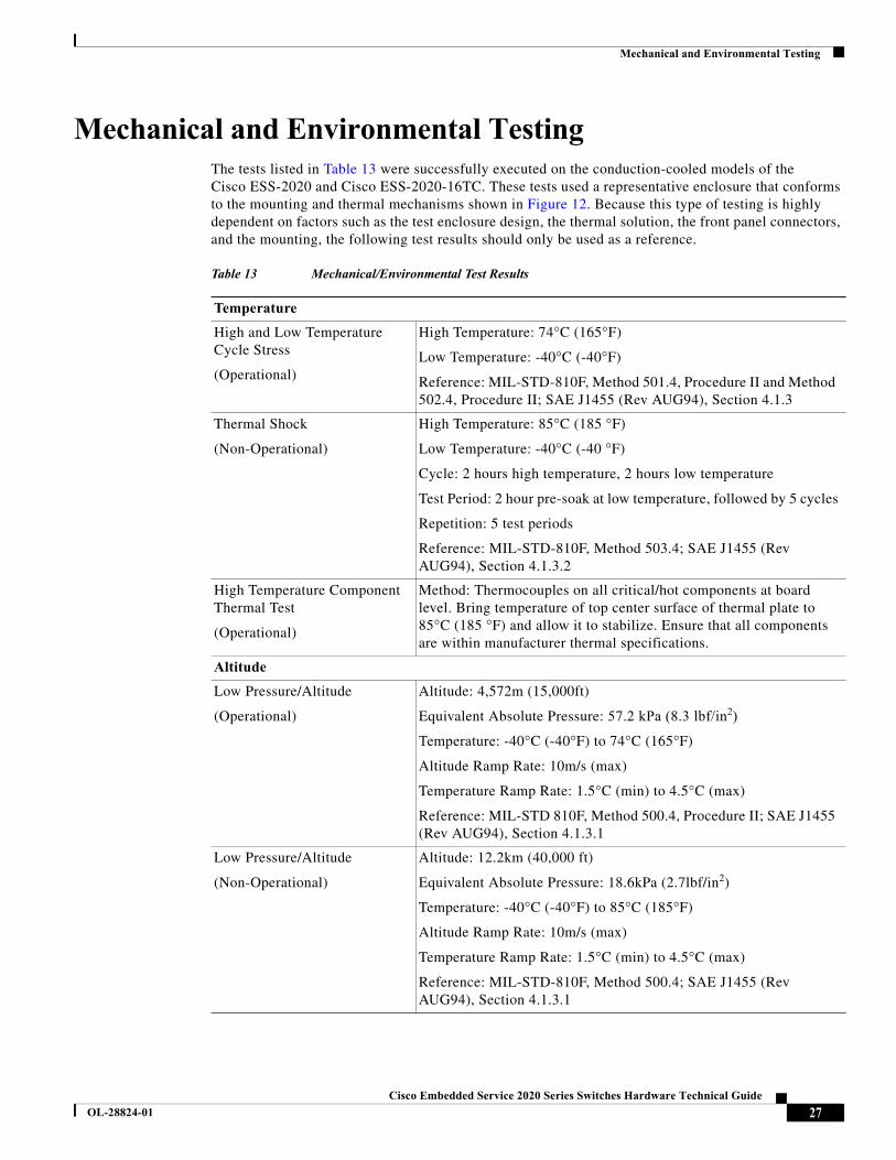
Mechanical and Environmental TestingThe tests listed in Table 13 were successfully executed on the conduction-cooled models of the Cisco ESS-2020 and Cisco ESS-2020-16TC. These tests used a representative enclosure that conforms to the mounting and thermal mechanisms shown in Figure 12. Because this type of testing is highly dependent on factors such as the test enclosure design, the thermal solution, the front panel connectors, and the mounting, the following test results should only be used as a reference.
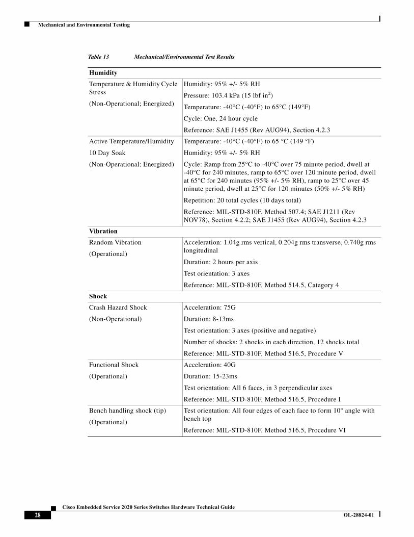
Table 13 Mechanical/Environmental Test Results
Temperature
High and Low Temperature Cycle Stress
(Operational)
High Temperature: 74°C (165°F)
Low Temperature: -40°C (-40°F)
Reference: MIL-STD-810F, Method 501.4, Procedure II and Method 502.4, Procedure II; SAE J1455 (Rev AUG94), Section 4.1.3
Thermal Shock
(Non-Operational)
High Temperature: 85°C (185 °F)
Low Temperature: -40°C (-40 °F)
Cycle: 2 hours high temperature, 2 hours low temperature
Test Period: 2 hour pre-soak at low temperature, followed by 5 cycles
Repetition: 5 test periods
Reference: MIL-STD-810F, Method 503.4; SAE J1455 (Rev AUG94), Section 4.1.3.2
High Temperature Component Thermal Test
(Operational)
Method: Thermocouples on all critical/hot components at board level. Bring temperature of top center surface of thermal plate to 85°C (185 °F) and allow it to stabilize. Ensure that all components are within manufacturer thermal specifications.
Altitude
Low Pressure/Altitude
(Operational)
Altitude: 4,572m (15,000ft)
Equivalent Absolute Pressure: 57.2 kPa (8.3 lbf/in2)
Temperature: -40°C (-40°F) to 74°C (165°F)
Altitude Ramp Rate: 10m/s (max)
Temperature Ramp Rate: 1.5°C (min) to 4.5°C (max)
Reference: MIL-STD 810F, Method 500.4, Procedure II; SAE J1455 (Rev AUG94), Section 4.1.3.1
Low Pressure/Altitude
(Non-Operational)
Altitude: 12.2km (40,000 ft)
Equivalent Absolute Pressure: 18.6kPa (2.7lbf/in2)
Temperature: -40°C (-40°F) to 85°C (185°F)
Altitude Ramp Rate: 10m/s (max)
Temperature Ramp Rate: 1.5°C (min) to 4.5°C (max)
Reference: MIL-STD-810F, Method 500.4; SAE J1455 (Rev AUG94), Section 4.1.3.1
27Cisco Embedded Service 2020 Series Switches Hardware Technical Guide
OL-28824-01
Mechanical and Environmental Testing
Humidity
Temperature & Humidity Cycle Stress
(Non-Operational; Energized)
Humidity: 95% +/- 5% RH
Pressure: 103.4 kPa (15 lbf in2)
Temperature: -40°C (-40°F) to 65°C (149°F)
Cycle: One, 24 hour cycle
Reference: SAE J1455 (Rev AUG94), Section 4.2.3
Active Temperature/Humidity
10 Day Soak
(Non-Operational; Energized)
Temperature: -40°C (-40°F) to 65 °C (149 °F)
Humidity: 95% +/- 5% RH
Cycle: Ramp from 25°C to -40°C over 75 minute period, dwell at -40°C for 240 minutes, ramp to 65°C over 120 minute period, dwell at 65°C for 240 minutes (95% +/- 5% RH), ramp to 25°C over 45 minute period, dwell at 25°C for 120 minutes (50% +/- 5% RH)
Repetition: 20 total cycles (10 days total)
Reference: MIL-STD-810F, Method 507.4; SAE J1211 (Rev NOV78), Section 4.2.2; SAE J1455 (Rev AUG94), Section 4.2.3
Vibration
Random Vibration
(Operational)
Acceleration: 1.04g rms vertical, 0.204g rms transverse, 0.740g rms longitudinal
Duration: 2 hours per axis
Test orientation: 3 axes
Reference: MIL-STD-810F, Method 514.5, Category 4
Shock
Crash Hazard Shock
(Non-Operational)
Acceleration: 75G
Duration: 8-13ms
Test orientation: 3 axes (positive and negative)
Number of shocks: 2 shocks in each direction, 12 shocks total
Reference: MIL-STD-810F, Method 516.5, Procedure V
Functional Shock
(Operational)
Acceleration: 40G
Duration: 15-23ms
Test orientation: All 6 faces, in 3 perpendicular axes
Reference: MIL-STD-810F, Method 516.5, Procedure I
Bench handling shock (tip)
(Operational)
Test orientation: All four edges of each face to form 10° angle with bench top
Reference: MIL-STD-810F, Method 516.5, Procedure VI
Table 13 Mechanical/Environmental Test Results
28Cisco Embedded Service 2020 Series Switches Hardware Technical Guide
OL-28824-01
Factory Default Feature
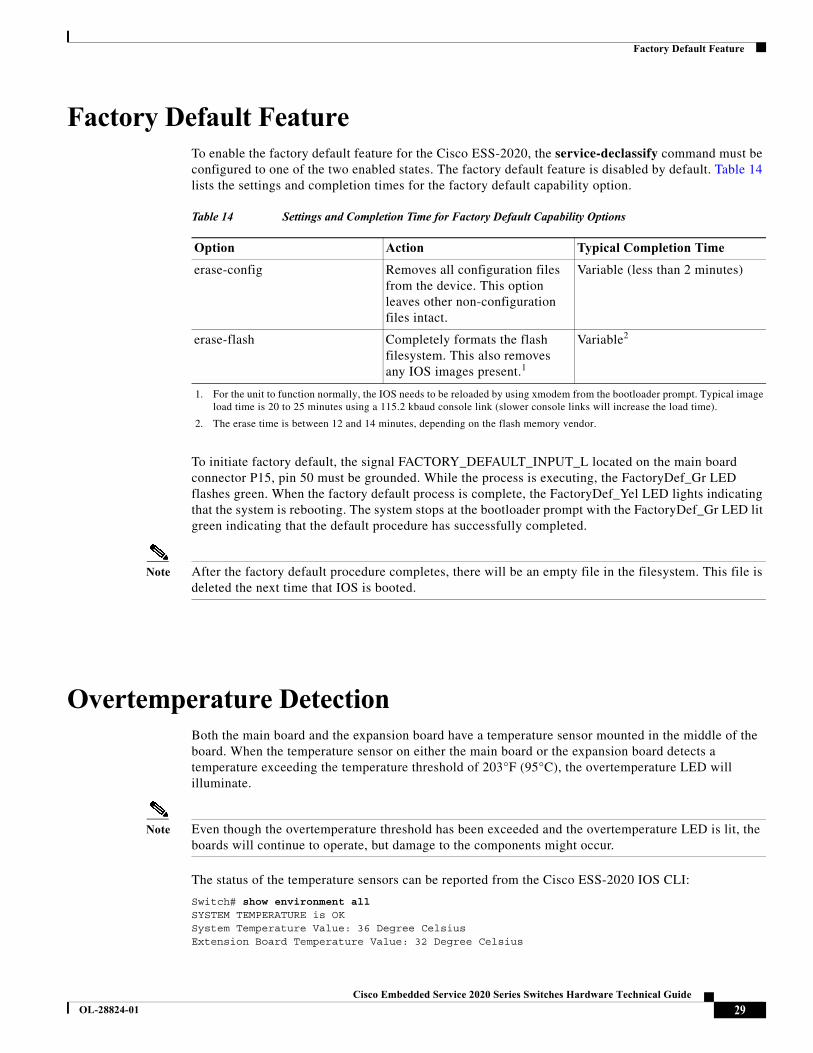
Factory Default FeatureTo enable the factory default feature for the Cisco ESS-2020, the service-declassify command must be configured to one of the two enabled states. The factory default feature is disabled by default. Table 14 lists the settings and completion times for the factory default capability option.
To initiate factory default, the signal FACTORY_DEFAULT_INPUT_L located on the main board connector P15, pin 50 must be grounded. While the process is executing, the FactoryDef_Gr LED flashes green. When the factory default process is complete, the FactoryDef_Yel LED lights indicating that the system is rebooting. The system stops at the bootloader prompt with the FactoryDef_Gr LED lit green indicating that the default procedure has successfully completed.
Note After the factory default procedure completes, there will be an empty file in the filesystem. This file is deleted the next time that IOS is booted.
Overtemperature DetectionBoth the main board and the expansion board have a temperature sensor mounted in the middle of the board. When the temperature sensor on either the main board or the expansion board detects a temperature exceeding the temperature threshold of 203°F (95°C), the overtemperature LED will illuminate.
Note Even though the overtemperature threshold has been exceeded and the overtemperature LED is lit, the boards will continue to operate, but damage to the components might occur.
The status of the temperature sensors can be reported from the Cisco ESS-2020 IOS CLI:
Switch# show environment allSYSTEM TEMPERATURE is OKSystem Temperature Value: 36 Degree CelsiusExtension Board Temperature Value: 32 Degree Celsius
Table 14 Settings and Completion Time for Factory Default Capability Options
Option Action Typical Completion Time
erase-config Removes all configuration files from the device. This option leaves other non-configuration files intact.
Variable (less than 2 minutes)
erase-flash Completely formats the flash filesystem. This also removes any IOS images present.1
1. For the unit to function normally, the IOS needs to be reloaded by using xmodem from the bootloader prompt. Typical image load time is 20 to 25 minutes using a 115.2 kbaud console link (slower console links will increase the load time).
Variable2
2. The erase time is between 12 and 14 minutes, depending on the flash memory vendor.
29Cisco Embedded Service 2020 Series Switches Hardware Technical Guide
OL-28824-01
Thermal Design Considerations
Thermal Design ConsiderationsThe following sections outline the methods for dealing with thermal issues and the mounting options involving the Cisco-designed conduction cooling plate.
Models with Thermal Plate
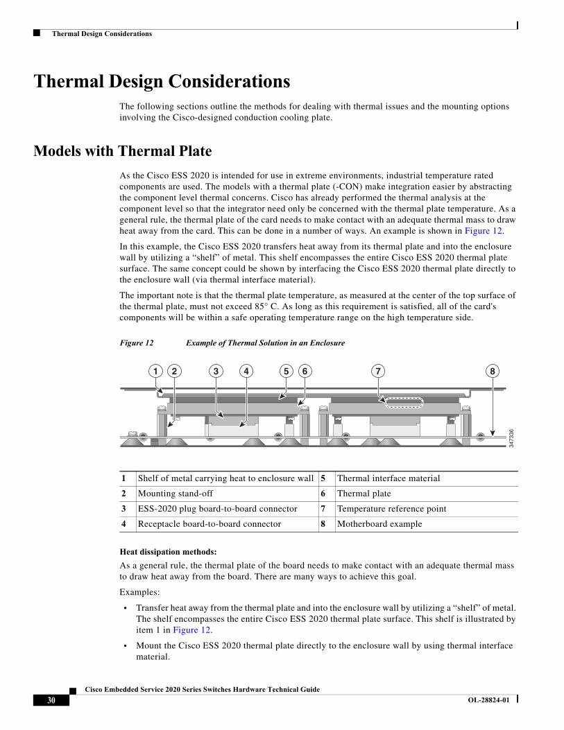
As the Cisco ESS 2020 is intended for use in extreme environments, industrial temperature rated components are used. The models with a thermal plate (-CON) make integration easier by abstracting the component level thermal concerns. Cisco has already performed the thermal analysis at the component level so that the integrator need only be concerned with the thermal plate temperature. As a general rule, the thermal plate of the card needs to make contact with an adequate thermal mass to draw heat away from the card. This can be done in a number of ways. An example is shown in Figure 12.
In this example, the Cisco ESS 2020 transfers heat away from its thermal plate and into the enclosure wall by utilizing a “shelf” of metal. This shelf encompasses the entire Cisco ESS 2020 thermal plate surface. The same concept could be shown by interfacing the Cisco ESS 2020 thermal plate directly to the enclosure wall (via thermal interface material).
The important note is that the thermal plate temperature, as measured at the center of the top surface of the thermal plate, must not exceed 85° C. As long as this requirement is satisfied, all of the card's components will be within a safe operating temperature range on the high temperature side.
Figure 12 Example of Thermal Solution in an Enclosure
Heat dissipation methods:
As a general rule, the thermal plate of the board needs to make contact with an adequate thermal mass to draw heat away from the board. There are many ways to achieve this goal.
Examples:
• Transfer heat away from the thermal plate and into the enclosure wall by utilizing a “shelf” of metal. The shelf encompasses the entire Cisco ESS 2020 thermal plate surface. This shelf is illustrated by item 1 in Figure 12.
• Mount the Cisco ESS 2020 thermal plate directly to the enclosure wall by using thermal interface material.
1 Shelf of metal carrying heat to enclosure wall 5 Thermal interface material
2 Mounting stand-off 6 Thermal plate
3 ESS-2020 plug board-to-board connector 7 Temperature reference point
4 Receptacle board-to-board connector 8 Motherboard example
3473
36
85 6421 3 7
30Cisco Embedded Service 2020 Series Switches Hardware Technical Guide
OL-28824-01
Thermal Design Considerations
• Attach card retainers to the extended edges of the thermal plate. The board retainers would then make contact with a thermal mass or the enclosure where the heat from the Cisco ESS 2020 will be conducted. For more information, see Mounting Options for the Cisco-Designed Thermal Plate.
Models Without Thermal Plate
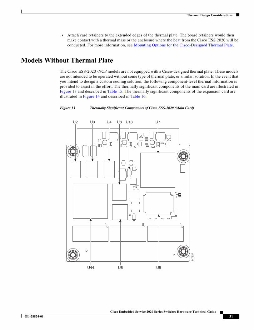
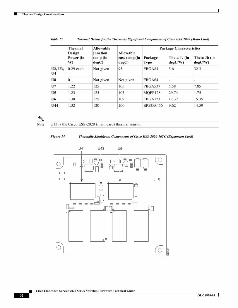
The Cisco ESS-2020 -NCP models are not equipped with a Cisco-designed thermal plate. These models are not intended to be operated without some type of thermal plate, or similar, solution. In the event that you intend to design a custom cooling solution, the following component-level thermal information is provided to assist in the effort. The thermally significant components of the main card are illustrated in Figure 13 and described in Table 15. The thermally significant components of the expansion card are illustrated in Figure 14 and described in Table 16.
Figure 13 Thermally Significant Components of Cisco ESS-2020 (Main Card)
3473
37
U2 U3 U4 U8 U13 U7
U44 U6 U5
31Cisco Embedded Service 2020 Series Switches Hardware Technical Guide
OL-28824-01
Thermal Design Considerations
Note U13 is the Cisco ESS-2020 (main card) thermal sensor.
Figure 14 Thermally Significant Components of Cisco ESS-2020-16TC (Expansion Card)
Table 15 Thermal Details for the Thermally Significant Components of Cisco ESS 2020 (Main Card)
Thermal Design Power (in W)
Allowable junction temp (in degC)
Allowable case temp (in degC)
Package Characteristics
Package Type
Theta Jc (in degC/W)
Theta Jb (in degC/W)
U2, U3, U4
0.29 each Not given 95 FBGA84 5.6 32.3
U8 0.1 Not given Not given FBGA64 - -
U7 1.22 125 105 PBGA537 5.58 7.85
U5 1.23 125 105 MQFP128 29.74 1.75
U6 1.38 125 109 FBGA121 12.32 15.35
U44 1.32 120 100 EPBGA456 9.62 14.59
3473
38
U5U43U41
32Cisco Embedded Service 2020 Series Switches Hardware Technical Guide
OL-28824-01
Thermal Design Considerations
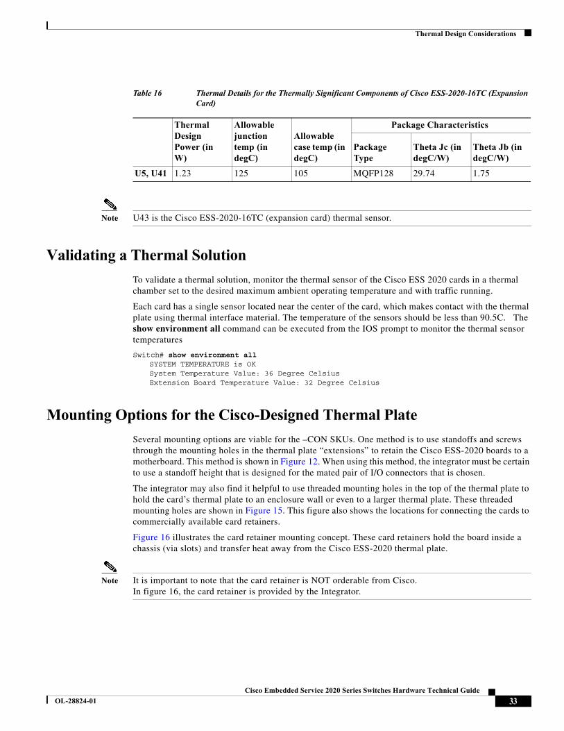
Note U43 is the Cisco ESS-2020-16TC (expansion card) thermal sensor.
Validating a Thermal Solution
To validate a thermal solution, monitor the thermal sensor of the Cisco ESS 2020 cards in a thermal chamber set to the desired maximum ambient operating temperature and with traffic running.
Each card has a single sensor located near the center of the card, which makes contact with the thermal plate using thermal interface material. The temperature of the sensors should be less than 90.5C. The show environment all command can be executed from the IOS prompt to monitor the thermal sensor temperatures
Switch# show environment allSYSTEM TEMPERATURE is OKSystem Temperature Value: 36 Degree CelsiusExtension Board Temperature Value: 32 Degree Celsius
Mounting Options for the Cisco-Designed Thermal Plate
Several mounting options are viable for the –CON SKUs. One method is to use standoffs and screws through the mounting holes in the thermal plate “extensions” to retain the Cisco ESS-2020 boards to a motherboard. This method is shown in Figure 12. When using this method, the integrator must be certain to use a standoff height that is designed for the mated pair of I/O connectors that is chosen.
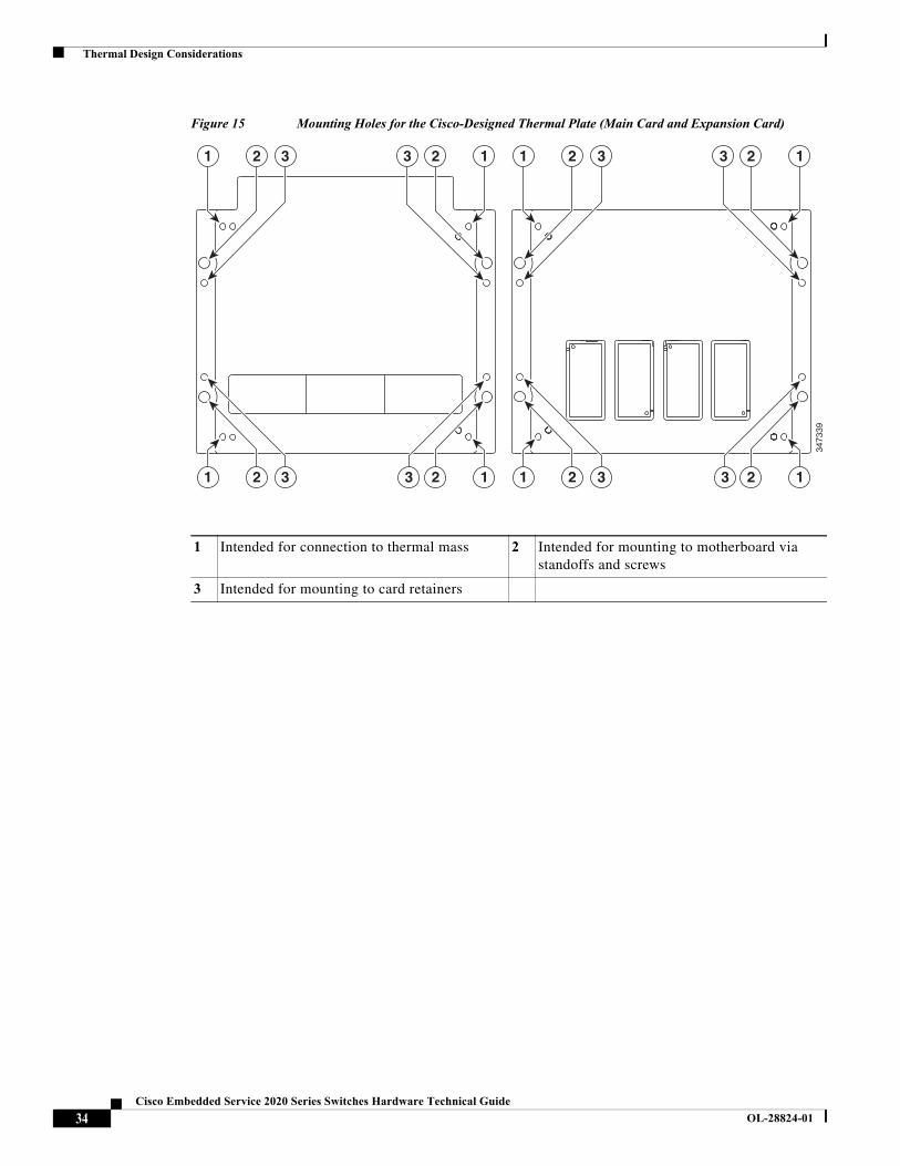
The integrator may also find it helpful to use threaded mounting holes in the top of the thermal plate to hold the card’s thermal plate to an enclosure wall or even to a larger thermal plate. These threaded mounting holes are shown in Figure 15. This figure also shows the locations for connecting the cards to commercially available card retainers.
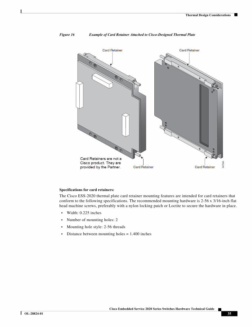
Figure 16 illustrates the card retainer mounting concept. These card retainers hold the board inside a chassis (via slots) and transfer heat away from the Cisco ESS-2020 thermal plate.
Note It is important to note that the card retainer is NOT orderable from Cisco. In figure 16, the card retainer is provided by the Integrator.
Table 16 Thermal Details for the Thermally Significant Components of Cisco ESS-2020-16TC (Expansion Card)
Thermal Design Power (in W)
Allowable junction temp (in degC)
Allowable case temp (in degC)
Package Characteristics
Package Type
Theta Jc (in degC/W)
Theta Jb (in degC/W)
U5, U41 1.23 125 105 MQFP128 29.74 1.75
33Cisco Embedded Service 2020 Series Switches Hardware Technical Guide
OL-28824-01
Thermal Design Considerations
Figure 15 Mounting Holes for the Cisco-Designed Thermal Plate (Main Card and Expansion Card)
3473
39
21
2
3
31
123
123
3
3
3
3
21
21
12
12
1 Intended for connection to thermal mass 2 Intended for mounting to motherboard via standoffs and screws
3 Intended for mounting to card retainers
34Cisco Embedded Service 2020 Series Switches Hardware Technical Guide
OL-28824-01
Thermal Design Considerations
Figure 16 Example of Card Retainer Attached to Cisco-Designed Thermal Plate
Specifications for card retainers:
The Cisco ESS-2020 thermal plate card retainer mounting features are intended for card retainers that conform to the following specifications. The recommended mounting hardware is 2-56 x 3/16-inch flat head machine screws, preferably with a nylon locking patch or Loctite to secure the hardware in place.
• Width: 0.225 inches
• Number of mounting holes: 2
• Mounting hole style: 2-56 threads
• Distance between mounting holes = 1.400 inches
35Cisco Embedded Service 2020 Series Switches Hardware Technical Guide
OL-28824-01
Thermal Design Considerations
Sandwich Configuration
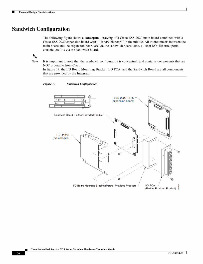
The following figure shows a conceptual drawing of a Cisco ESS 2020 main board combined with a Cisco ESS 2020 expansion board with a “sandwich board” in the middle. All interconnects between the main board and the expansion board are via the sandwich board; also, all user I/O (Ethernet ports, console, etc.) is via the sandwich board.
Note It is important to note that the sandwich configuration is conceptual, and contains components that are NOT orderable from Cisco. In figure 17, the I/O Board Mounting Bracket, I/O PCA, and the Sandwich Board are all components that are provided by the Integrator.
Figure 17 Sandwich Configuration
36Cisco Embedded Service 2020 Series Switches Hardware Technical Guide
OL-28824-01
Product Specifications
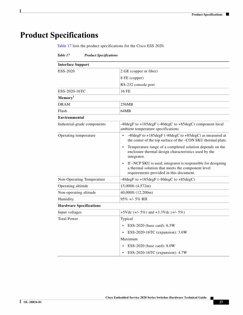
Product SpecificationsTable 17 lists the product specifications for the Cisco ESS 2020.
Table 17 Product Specifications
Interface Support
ESS-2020 2 GE (copper or fiber)
8 FE (copper)
RS-232 console port
ESS-2020-16TC 16 FE
Memory1
DRAM 256MB
Flash 64MB
Environmental
Industrial-grade components -40degF to +185degF (-40degC to +85degC) component local ambient temperature specifications
Operating temperature • -40degF to +185degF (-40degC to +85degC) as measured at the center of the top surface of the –CON SKU thermal plate.
• Temperature range of a completed solution depends on the enclosure thermal design characteristics used by the integrator.
• If –NCP SKU is used, integrator is responsible for designing a thermal solution that meets the component level requirements provided in this document.
Non-Operating Temperature -40degF to +185degF (-40degC to +85degC)
Operating altitude 15,000ft (4,572m)
Non-operating altitude 40,000ft (12,200m)
Humidity 95% +/- 5% RH
Hardware Specifications
Input voltages +5Vdc (+/- 5%) and +3.3Vdc (+/- 5%)
Total Power Typical
• ESS-2020 (base card): 6.5W
• ESS-2020-16TC (expansion): 3.6W
Maximum
• ESS-2020 (base card): 8.0W
• ESS-2020-16TC (expansion): 4.7W
37Cisco Embedded Service 2020 Series Switches Hardware Technical Guide
OL-28824-01
Power Requirements
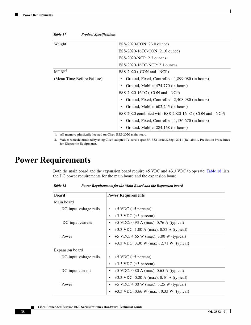
Power RequirementsBoth the main board and the expansion board require +5 VDC and +3.3 VDC to operate. Table 18 lists the DC power requirements for the main board and the expansion board.
Weight ESS-2020-CON: 23.0 ounces
ESS-2020-16TC-CON: 21.6 ounces
ESS-2020-NCP: 2.3 ounces
ESS-2020-16TC-NCP: 2.1 ounces
MTBF2
(Mean Time Before Failure)
ESS-2020 (-CON and –NCP)
• Ground, Fixed, Controlled: 1,899,080 (in hours)
• Ground, Mobile: 474,770 (in hours)
ESS-2020-16TC (-CON and –NCP)
• Ground, Fixed, Controlled: 2,408,980 (in hours)
• Ground, Mobile: 602,245 (in hours)
ESS-2020 combined with ESS-2020-16TC (-CON and –NCP)
• Ground, Fixed, Controlled: 1,136,670 (in hours)
• Ground, Mobile: 284,168 (in hours)
1. All memory physically located on Cisco ESS-2020 main board.
2. Values were determined by using Cisco-adopted Telcordia spec SR-332 Issue 3, Sept. 2011 (Reliability Prediction Procedures for Electronic Equipment).
Table 17 Product Specifications
Table 18 Power Requirements for the Main Board and the Expansion board
Board Power Requirements
Main board
DC-input voltage rails • +5 VDC (±5 percent)
• +3.3 VDC (±5 percent)
DC-input current • +5 VDC: 0.93 A (max), 0.76 A (typical)
• +3.3 VDC: 1.00 A (max), 0.82 A (typical)
Power • +5 VDC: 4.65 W (max), 3.80 W (typical)
• +3.3 VDC: 3.30 W (max), 2.71 W (typical)
Expansion board
DC-input voltage rails • +5 VDC (±5 percent)
• +3.3 VDC (±5 percent)
DC-input current • +5 VDC: 0.80 A (max), 0.65 A (typical)
• +3.3 VDC: 0.20 A (max), 0.10 A (typical)
Power • +5 VDC: 4.00 W (max), 3.25 W (typical)
• +3.3 VDC: 0.66 W (max), 0.33 W (typical)
38Cisco Embedded Service 2020 Series Switches Hardware Technical Guide
OL-28824-01

Power Requirements
Note There are no voltage rail-sequencing requirements. Power supply voltage rails can power-up or power-down in any order. Both +3.3 VDC and 5 VDC rails are required by the ESS-2020.
39Cisco Embedded Service 2020 Series Switches Hardware Technical Guide
OL-28824-01
SFP Support
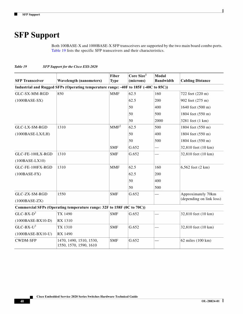
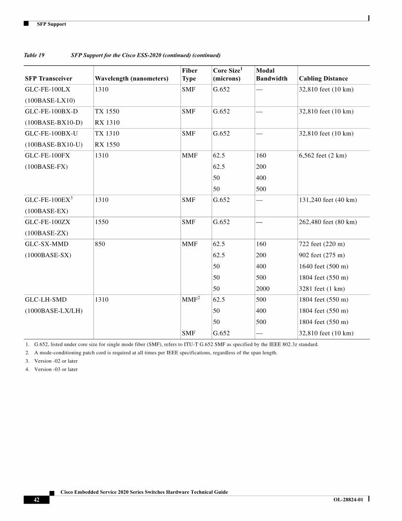
SFP SupportBoth 100BASE-X and 1000BASE-X SFP transceivers are supported by the two main board combo ports. Table 19 lists the specific SFP transceivers and their characteristics.
Table 19 SFP Support for the Cisco ESS-2020
SFP Transceiver Wavelength (nanometers)Fiber Type
Core Size1 (microns)
Modal Bandwidth Cabling Distance
Industrial and Rugged SFPs (Operating temperature range: -40F to 185F (-40C to 85C))
GLC-SX-MM-RGD
(1000BASE-SX)
850 MMF 62.5
62.5
50
50
50
160
200
400
500
2000
722 feet (220 m)
902 feet (275 m)
1640 feet (500 m)
1804 feet (550 m)
3281 feet (1 km)
GLC-LX-SM-RGD
(1000BASE-LX/LH)
1310 MMF2
SMF
62.5
50
50
G.652
500
400
500
—
1804 feet (550 m)
1804 feet (550 m)
1804 feet (550 m)
32,810 feet (10 km)
GLC-FE-100LX-RGD
(100BASE-LX10)
1310 SMF G.652 — 32,810 feet (10 km)
GLC-FE-100FX-RGD
(100BASE-FX)
1310 MMF 62.5
62.5
50
50
160
200
400
500
6,562 feet (2 km)
GLC-ZX-SM-RGD
(1000BASE-ZX)
1550 SMF G.652 — Approximately 70km (depending on link loss)
Commercial SFPs (Operating temperature range: 32F to 158F (0C to 70C))
GLC-BX-D3
(1000BASE-BX10-D)
TX 1490
RX 1310
SMF G.652 — 32,810 feet (10 km)
GLC-BX-U3
(1000BASE-BX10-U)
TX 1310
RX 1490
SMF G.652 — 32,810 feet (10 km)
CWDM-SFP 1470, 1490, 1510, 1530, 1550, 1570, 1590, 1610
SMF G.652 — 62 miles (100 km)
40Cisco Embedded Service 2020 Series Switches Hardware Technical Guide
OL-28824-01
SFP Support
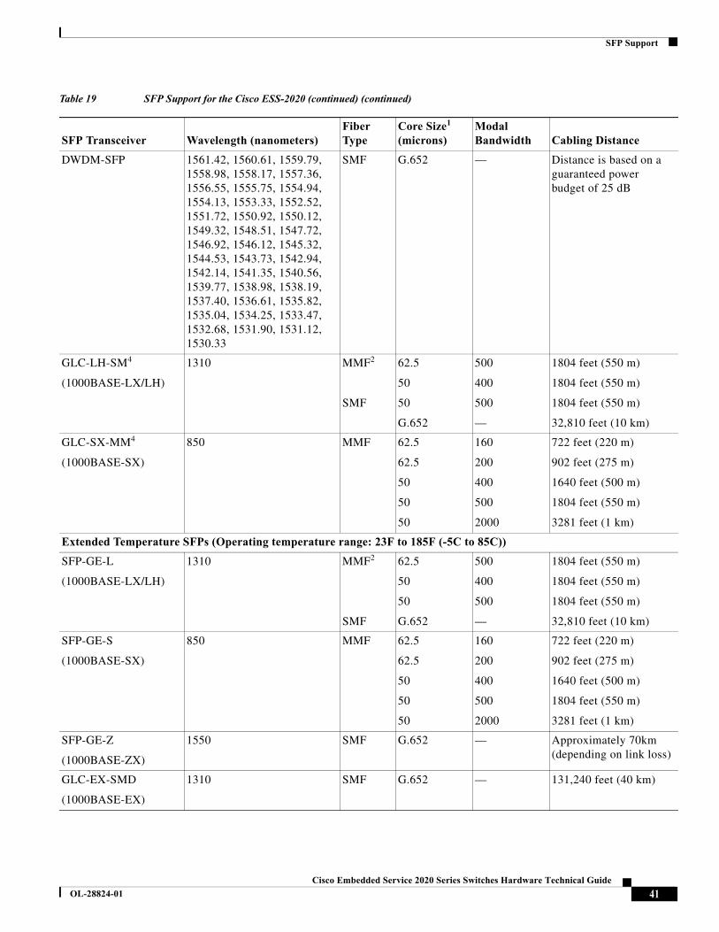
DWDM-SFP 1561.42, 1560.61, 1559.79, 1558.98, 1558.17, 1557.36, 1556.55, 1555.75, 1554.94, 1554.13, 1553.33, 1552.52, 1551.72, 1550.92, 1550.12, 1549.32, 1548.51, 1547.72, 1546.92, 1546.12, 1545.32, 1544.53, 1543.73, 1542.94, 1542.14, 1541.35, 1540.56, 1539.77, 1538.98, 1538.19, 1537.40, 1536.61, 1535.82, 1535.04, 1534.25, 1533.47, 1532.68, 1531.90, 1531.12, 1530.33
SMF G.652 — Distance is based on a guaranteed power budget of 25 dB
GLC-LH-SM4
(1000BASE-LX/LH)
1310 MMF2
SMF
62.5
50
50
G.652
500
400
500
—
1804 feet (550 m)
1804 feet (550 m)
1804 feet (550 m)
32,810 feet (10 km)
GLC-SX-MM4
(1000BASE-SX)
850 MMF 62.5
62.5
50
50
50
160
200
400
500
2000
722 feet (220 m)
902 feet (275 m)
1640 feet (500 m)
1804 feet (550 m)
3281 feet (1 km)
Extended Temperature SFPs (Operating temperature range: 23F to 185F (-5C to 85C))
SFP-GE-L
(1000BASE-LX/LH)
1310 MMF2
SMF
62.5
50
50
G.652
500
400
500
—
1804 feet (550 m)
1804 feet (550 m)
1804 feet (550 m)
32,810 feet (10 km)
SFP-GE-S
(1000BASE-SX)
850 MMF 62.5
62.5
50
50
50
160
200
400
500
2000
722 feet (220 m)
902 feet (275 m)
1640 feet (500 m)
1804 feet (550 m)
3281 feet (1 km)
SFP-GE-Z
(1000BASE-ZX)
1550 SMF G.652 — Approximately 70km (depending on link loss)
GLC-EX-SMD
(1000BASE-EX)
1310 SMF G.652 — 131,240 feet (40 km)
Table 19 SFP Support for the Cisco ESS-2020 (continued) (continued)
SFP Transceiver Wavelength (nanometers)Fiber Type
Core Size1 (microns)
Modal Bandwidth Cabling Distance
41Cisco Embedded Service 2020 Series Switches Hardware Technical Guide
OL-28824-01
SFP Support
GLC-FE-100LX
(100BASE-LX10)
1310 SMF G.652 — 32,810 feet (10 km)
GLC-FE-100BX-D
(100BASE-BX10-D)
TX 1550
RX 1310
SMF G.652 — 32,810 feet (10 km)
GLC-FE-100BX-U
(100BASE-BX10-U)
TX 1310
RX 1550
SMF G.652 — 32,810 feet (10 km)
GLC-FE-100FX
(100BASE-FX)
1310 MMF 62.5
62.5
50
50
160
200
400
500
6,562 feet (2 km)
GLC-FE-100EX3
(100BASE-EX)
1310 SMF G.652 — 131,240 feet (40 km)
GLC-FE-100ZX
(100BASE-ZX)
1550 SMF G.652 — 262,480 feet (80 km)
GLC-SX-MMD
(1000BASE-SX)
850 MMF 62.5
62.5
50
50
50
160
200
400
500
2000
722 feet (220 m)
902 feet (275 m)
1640 feet (500 m)
1804 feet (550 m)
3281 feet (1 km)
GLC-LH-SMD
(1000BASE-LX/LH)
1310 MMF2
SMF
62.5
50
50
G.652
500
400
500
—
1804 feet (550 m)
1804 feet (550 m)
1804 feet (550 m)
32,810 feet (10 km)
1. G.652, listed under core size for single mode fiber (SMF), refers to ITU-T G.652 SMF as specified by the IEEE 802.3z standard.
2. A mode-conditioning patch cord is required at all times per IEEE specifications, regardless of the span length.
3. Version -02 or later
4. Version -03 or later
Table 19 SFP Support for the Cisco ESS-2020 (continued) (continued)
SFP Transceiver Wavelength (nanometers)Fiber Type
Core Size1 (microns)
Modal Bandwidth Cabling Distance
42Cisco Embedded Service 2020 Series Switches Hardware Technical Guide
OL-28824-01
Regulatory Compliance and Safety Information
Regulatory Compliance and Safety Information
Statement 8000—Standards Compliance
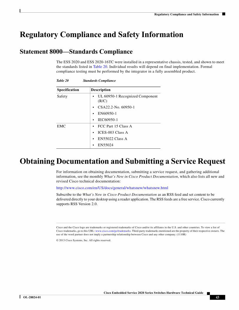
The ESS 2020 and ESS 2020-16TC were installed in a representative chassis, tested, and shown to meet the standards listed in Table 20. Individual results will depend on final implementation. Formal compliance testing must be performed by the integrator in a fully assembled product.
Obtaining Documentation and Submitting a Service RequestFor information on obtaining documentation, submitting a service request, and gathering additional information, see the monthly What’s New in Cisco Product Documentation, which also lists all new and revised Cisco technical documentation:
http://www.cisco.com/en/US/docs/general/whatsnew/whatsnew.html
Subscribe to the What’s New in Cisco Product Documentation as an RSS feed and set content to be delivered directly to your desktop using a reader application. The RSS feeds are a free service. Cisco currently supports RSS Version 2.0.
Cisco and the Cisco logo are trademarks or registered trademarks of Cisco and/or its affiliates in the U.S. and other countries. To view a list of Cisco trademarks, go to this URL: www.cisco.com/go/trademarks. Third-party trademarks mentioned are the property of their respective owners. The use of the word partner does not imply a partnership relationship between Cisco and any other company. (1110R)
© 2013 Cisco Systems, Inc. All rights reserved.
Table 20 Standards Compliance
Specification Description
Safety • UL 60950-1 Recognized Component (R/C)
• CSA22.2-No. 60950-1
• EN60950-1
• IEC60950-1
EMC • FCC Part 15 Class A
• ICES-003 Class A
• EN55022 Class A
• EN55024
43Cisco Embedded Service 2020 Series Switches Hardware Technical Guide
OL-28824-01

Obtaining Documentation and Submitting a Service Request
44Cisco Embedded Service 2020 Series Switches Hardware Technical Guide
OL-28824-01