cisco aironet 5-ghz mimo wall-mounted … · 2 cisco aironet 5-ghz mimo wall-mounted...
TRANSCRIPT

Americas Headquarters:
© 2010 Cisco Systems, Inc. All rights reserved.
Cisco Systems, Inc., 170 West Tasman Drive, San Jose, CA 95134-1706 USA
Cisco Aironet 5-GHz MIMO Wall-Mounted Omnidirectional Antenna (AIR-ANT5140NV-R)
This document outlines the specifications for the Cisco Aironet 5-GHz MIMO Wall-Mounted Omnidirectional Antenna (AIR-ANT5140NV-R) and provides instructions for mounting it. The antenna operates in the 5-GHz frequency range and is designed for indoor or outdoor use.
The following information is provided in this document.
• Technical Specifications, page 2
• System Requirements, page 5
• Safety Precautions, page 6
• Installation Notes, page 7
• Suggested Cable, page 14
• Obtaining Documentation and Submitting a Service Request, page 14

2Cisco Aironet 5-GHz MIMO Wall-Mounted Omnidirectional Antenna (AIR-ANT5140NV-R)
78-19615-01
Technical Specifications
Technical Specifications
Antenna type 3-element MIMO omnidirectional
Operating frequency range
5150 – 5850 MHz
VSWR 2:1 or less
Peak gain 4 dBi
Polarization Linear, vertical
Azimuth plane (3 dB beamwidth)
Ominidirectional
Elevation plane (3 dB beamwidth
36°
Length 8.6 in (21.8 cm)
Diameter 6.3 in (16 cm)
Weight Antenna: 1.33 lb (623.6 g);
Antenna and packaging: 3.39 lb (1.54 kg)
Cable 3-ft. (91.4 cm) plenum rated with blue ID markers
Connector RP-TNC
Environment Indoor/outdoor
Temperature range -22° F to 158° F(-30° C to 70° C)
2083
60
3Cisco Aironet 5-GHz MIMO Wall-Mounted Omnidirectional Antenna (AIR-ANT5140NV-R)
78-19615-01
Technical Specifications
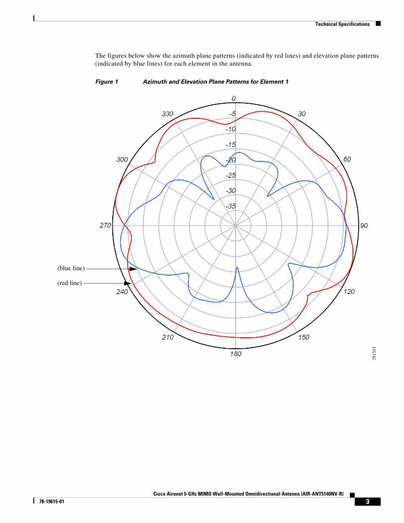
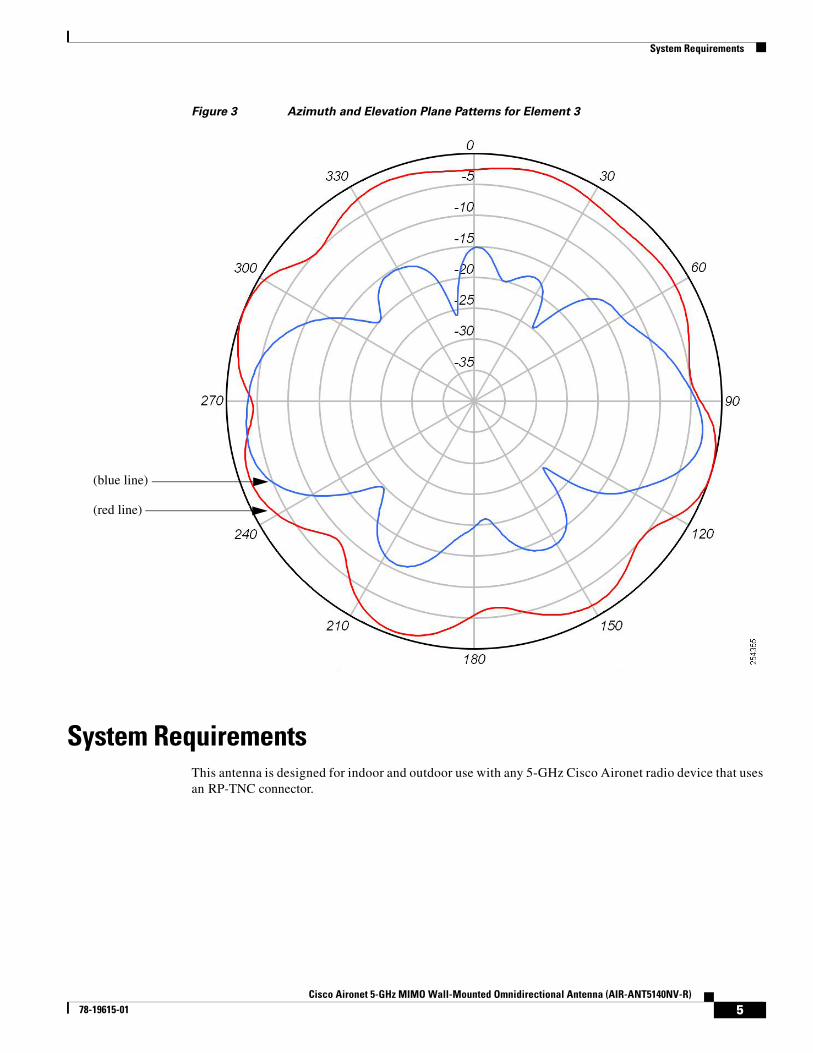
The figures below show the azimuth plane patterns (indicated by red lines) and elevation plane patterns (indicated by blue lines) for each element in the antenna.
Figure 1 Azimuth and Elevation Plane Patterns for Element 1
(blue line)
(red line)

4Cisco Aironet 5-GHz MIMO Wall-Mounted Omnidirectional Antenna (AIR-ANT5140NV-R)
78-19615-01
Technical Specifications
Figure 2 Azimuth and Elevation Plane Patterns for Element 2
(blue line)
(red line)
5Cisco Aironet 5-GHz MIMO Wall-Mounted Omnidirectional Antenna (AIR-ANT5140NV-R)
78-19615-01
System Requirements
Figure 3 Azimuth and Elevation Plane Patterns for Element 3
System RequirementsThis antenna is designed for indoor and outdoor use with any 5-GHz Cisco Aironet radio device that uses an RP-TNC connector.
(blue line)
(red line)

6Cisco Aironet 5-GHz MIMO Wall-Mounted Omnidirectional Antenna (AIR-ANT5140NV-R)
78-19615-01
Safety Precautions
Safety Precautions
Warning Do not locate the antenna near overhead power lines or other electric light or power circuits, or where it can come into contact with such circuits. When installing the antenna, take extreme care not to come into contact with such circuits, as they may cause serious injury or death. For proper installation and grounding of the antenna, please refer to national and local codes (e.g. U.S.: NFPA 70, National Electrical Code, Article 810, Canada: Canadian Electrical Code, Section 54). Statement 280
For your safety, read and follow these safety precautions.
1. Before you install an antenna, contact your Cisco account representative to explain which mounting method to use for the size and type of antenna that you are about to install.
2. Find someone to help you—installing an antenna is often a two-person job.
3. Select your installation site with safety, as well as performance, in mind. Remember that electric power lines and phone lines look alike. For your safety, assume that any overhead line can kill you.
4. Contact your electric power company. Tell them your plans and ask them to come look at your proposed installation.
5. Plan your installation carefully and completely before you begin. Each person involved in an installation should be assigned to a specific task, and should know what to do and when to do it. One person should be in charge of the operation to issue instructions and watch for signs of trouble.
6. When installing your antenna, follow these guidelines:
a. Do not use a metal ladder.
b. Do not work on a wet or windy day.
c. Do dress properly—wear shoes with rubber soles and heels, rubber gloves, and a long-sleeved shirt or jacket.
7. If the assembly starts to drop, move away from it and let it fall. Because the antenna, mast, cable, and metal guy wires are all excellent conductors of electrical current, even the slightest touch of any of these parts to a power line completes an electrical path through the antenna and the installer.
8. If any part of the antenna system should come in contact with a power line, do not touch it or try to remove it yourself. Call your local power company to have it removed safely.
9. If an accident should occur with the power lines, call for qualified emergency help immediately.
7Cisco Aironet 5-GHz MIMO Wall-Mounted Omnidirectional Antenna (AIR-ANT5140NV-R)
78-19615-01
Installation Notes
Installation NotesAntennas transmit and receive radio signals which are susceptible to RF obstructions and common sources of interference that can reduce throughput and range of the device to which they are connected. Follow these guidelines to ensure the best possible performance:
• Install the antenna vertically and mount it with the cables pointing towards the ground.
• Keep the antenna away from metal obstructions such as heating and air-conditioning ducts, large ceiling trusses, building superstructures, and major power cabling runs. If necessary, use a rigid conduit to lower the antenna away from these obstructions.
• The density of the materials used in a building’s construction determines the number of walls the signal can pass through and still maintain adequate signal strength. Consider the following before choosing the location for your antenna:
– Signals penetrate paper and vinyl walls with little change to signal strength.
– Signals penetrate only one or two solid and pre-cast concrete walls without degrading signal strength.
– Signals penetrate three or four concrete and wood block walls without degrading signal strength.
– Signals penetrate five or six walls constructed of drywall or wood without degrading signal strength.
– Signals will likely reflect off a thick metal wall and may not penetrate it at all.
– Signals will likely reflect off a chain link fence or wire mesh spaced between 1 and 1 1/2 in. (2.5 and 3.8 cm). The fence acts as a harmonic reflector that blocks the signal.
• Install the antenna away from microwave ovens and 2-GHz cordless phones. These products can cause signal interference because they operate in the same frequency range as the device to which your antenna is connected.
Choosing a Mounting LocationThe antenna should be mounted clear of any obstructions to the sides of the radiating elements. Generally, the higher an antenna is above the floor, the better it performs. If possible, find a mounting place directly above your wireless device to ensure the lead-in cable can be as short as possible.

8Cisco Aironet 5-GHz MIMO Wall-Mounted Omnidirectional Antenna (AIR-ANT5140NV-R)
78-19615-01
Installing the Antenna
Installing the AntennaYou can install the antenna on any flat vertical surface, on a pole, or on a ceiling. All hardware for mounting the antenna on a wall or ceiling is provided. If you intend to install your antenna on another surface, you must provide the appropriate hardware.
Tools and Equipment RequiredA mounting installation kit is included with the antenna and consists of the following hardware:
• Mount interface bracket
• Mount base
• Wall bracket
• One 1/4–20 x ½-in. cap screw
• One 1/4–20 wing screw
• Two #10 x ¾-in. screws
• Two #10 x ½-in. screws
• One screen mesh washer
• One spherical washer
• 3/16 allen wrench
• Rubber gasket
• Jam nut
You may need the following tools and equipment, which are not provided.
• A #2 Phillips screwdriver
• A drill and drill bit
• A pencil
• Two hose clamps
9Cisco Aironet 5-GHz MIMO Wall-Mounted Omnidirectional Antenna (AIR-ANT5140NV-R)
78-19615-01
Installing the Antenna
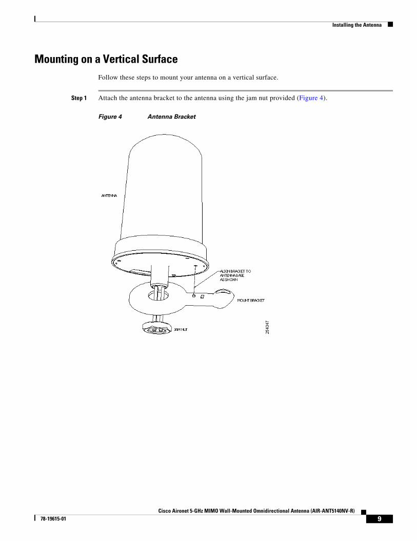
Mounting on a Vertical SurfaceFollow these steps to mount your antenna on a vertical surface.
Step 1 Attach the antenna bracket to the antenna using the jam nut provided (Figure 4).
Figure 4 Antenna Bracket
10Cisco Aironet 5-GHz MIMO Wall-Mounted Omnidirectional Antenna (AIR-ANT5140NV-R)
78-19615-01
Installing the Antenna
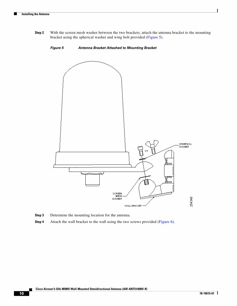
Step 2 With the screen mesh washer between the two brackets, attach the antenna bracket to the mounting bracket using the spherical washer and wing bolt provided (Figure 5).
Figure 5 Antenna Bracket Attached to Mounting Bracket
Step 3 Determine the mounting location for the antenna.
Step 4 Attach the wall bracket to the wall using the two screws provided (Figure 6).

11Cisco Aironet 5-GHz MIMO Wall-Mounted Omnidirectional Antenna (AIR-ANT5140NV-R)
78-19615-01
Installing the Antenna
Figure 6 Wall Mounting
Step 5 Slide the mounting bracket onto the wall bracket and secure it in place (optional) with the two screws provided (Figure 7).
Figure 7 Attaching Mounting Bracket to Wall Bracket
Once the antenna is secured on the wall, you can adjust the azimuth and elevation.
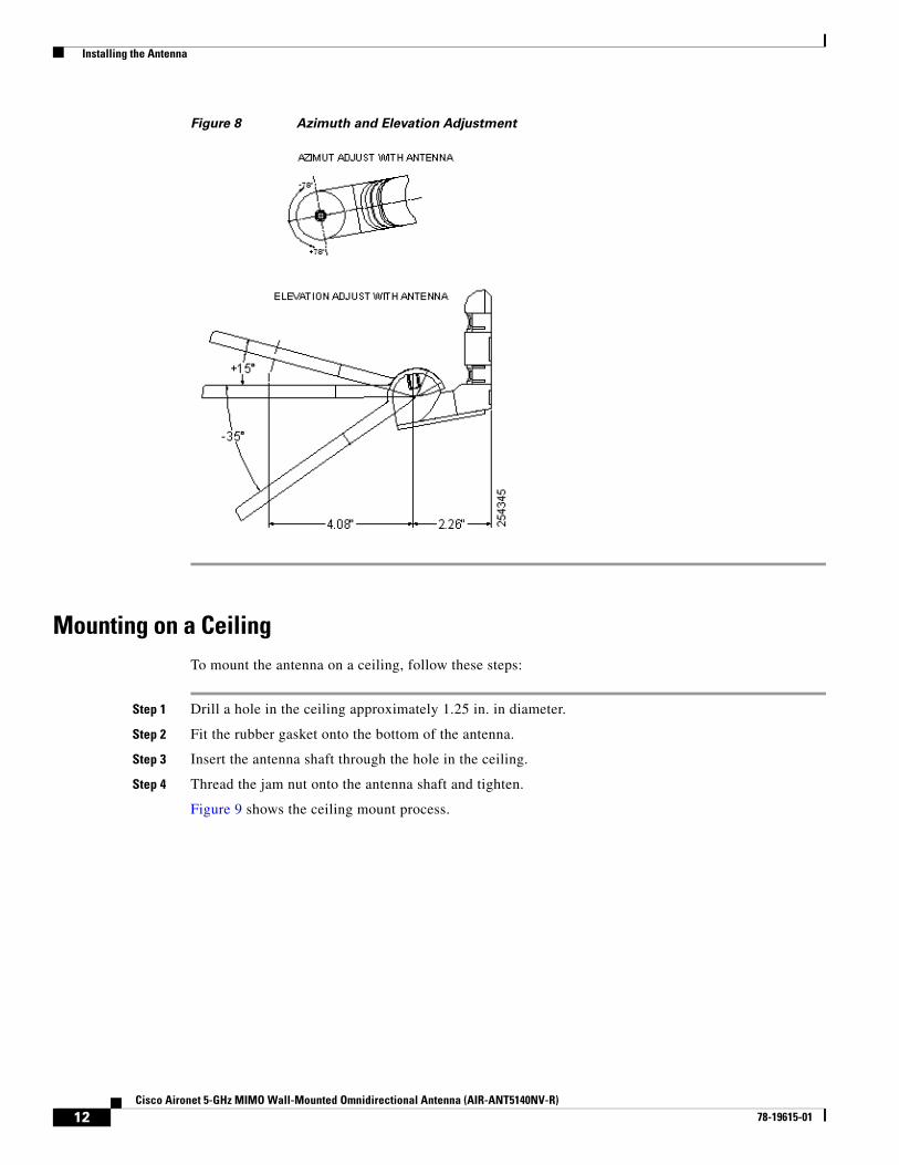
Step 6 To adjust the azimuth and elevation, loosen the bolt that attaches the antenna bracket to the mounting bracket (Figure 8). Azimuth can be adjusted ±90 degrees. Elevation can be adjusted +15 degrees and -35 degrees.
12Cisco Aironet 5-GHz MIMO Wall-Mounted Omnidirectional Antenna (AIR-ANT5140NV-R)
78-19615-01
Installing the Antenna
Figure 8 Azimuth and Elevation Adjustment
Mounting on a CeilingTo mount the antenna on a ceiling, follow these steps:
Step 1 Drill a hole in the ceiling approximately 1.25 in. in diameter.
Step 2 Fit the rubber gasket onto the bottom of the antenna.
Step 3 Insert the antenna shaft through the hole in the ceiling.
Step 4 Thread the jam nut onto the antenna shaft and tighten.
Figure 9 shows the ceiling mount process.

13Cisco Aironet 5-GHz MIMO Wall-Mounted Omnidirectional Antenna (AIR-ANT5140NV-R)
78-19615-01
Installing the Antenna
Figure 9 Mounting on a Ceiling
Mounting on a MastThe antenna can be mounted on a mast rather than on a wall using two 1/2 inch-wide hose clamps (not provided).
To mount the antenna on a mast, follow these steps:
Step 1 Follow Steps 1 and Step 2 from the “Mounting on a Vertical Surface” section on page 9.
Step 2 Position the antenna, mounting bracket, and hose clamps on the mast.
Step 3 Tighten the hose clamps until the antenna is secure on the mast.
Once the antenna is secured on the mast, you can adjust the azimuth and elevation.
14Cisco Aironet 5-GHz MIMO Wall-Mounted Omnidirectional Antenna (AIR-ANT5140NV-R)
78-19615-01
Obtaining Documentation and Submitting a Service Request
Step 4 To adjust the azimuth and elevation, loosen the bolt that attaches the antenna bracket to the mounting bracket (Figure 8). Azimuth can be adjusted ±90 degrees. Elevation can be adjusted +15 degrees and -35 degrees.
Suggested CableCisco recommends a high-quality, low-loss cable for use with the antenna.
Note Coaxial cable loses efficiency as the frequency increases, resulting in signal loss. The cable should be kept as short as possible because cable length also determines the amount of signal loss (the longer the run, the greater the loss).
Obtaining Documentation and Submitting a Service RequestFor information on obtaining documentation, submitting a service request, and gathering additional information, see the monthly What’s New in Cisco Product Documentation, which also lists all new and revised Cisco technical documentation, at:
http://www.cisco.com/en/US/docs/general/whatsnew/whatsnew.html
Subscribe to the What’s New in Cisco Product Documentation as a Really Simple Syndication (RSS) feed and set content to be delivered directly to your desktop using a reader application. The RSS feeds are a free service and Cisco currently supports RSS Version 2.0
Cisco and the Cisco Logo are trademarks of Cisco Systems, Inc. and/or its affiliates in the U.S. and other countries. A listing of Cisco's trademarks can be found at www.cisco.com/go/trademarks. Third party trademarks mentioned are the property of their respective owners. The use of the word partner does not imply a partnership relationship between Cisco and any other company. (1005R)