cisco adaptive security appliance (asa) virtual operational environment 1 7 cryptographic key...
TRANSCRIPT
Cisco Adaptive Security Appliance (ASA) Virtual
FIPS 140-2 Non Proprietary Security Policy Level 1 Validation
Version 0.3
June 2, 2016
Table of Contents
1 INTRODUCTION.................................................................................................................... 3
1.1 PURPOSE ............................................................................................................................. 3 1.2 MODULE VALIDATION LEVEL ............................................................................................ 3 1.3 REFERENCES ....................................................................................................................... 3 1.4 TERMINOLOGY ................................................................................................................... 4 1.5 DOCUMENT ORGANIZATION ............................................................................................... 4
2 CISCO ADAPTIVE SECURITY APPLIANCE (ASA) VIRTUAL .................................. 5
2.1 CISCO SERVERS .................................................................................................................. 5 2.2 CRYPTOGRAPHIC BOUNDARY ............................................................................................. 5
2.3 MODULE INTERFACES ......................................................................................................... 6 2.4 ROLES AND SERVICES ......................................................................................................... 7
User Services ....................................................................................................................................................................... 7 Crypto Officer Services ....................................................................................................................................................... 8
2.5 NON-FIPS MODE SERVICES ................................................................................................ 9 2.6 UNAUTHENTICATED SERVICES ......................................................................................... 10
2.7 CRYPTOGRAPHIC KEY/CSP MANAGEMENT ...................................................................... 10 2.8 CRYPTOGRAPHIC ALGORITHMS ........................................................................................ 15
Approved Cryptographic Algorithms ................................................................................................................................ 15 Non-FIPS Approved Algorithms Allowed in FIPS Mode ................................................................................................. 16 Non-Approved Cryptographic Algorithms ........................................................................................................................ 16
2.9 SELF-TESTS ...................................................................................................................... 17
3 SECURE OPERATION ...................................................................................................... 18
3.1 CRYPTO OFFICER GUIDANCE - SYSTEM INITIALIZATION .................................................. 18 3.2 CRYPTO OFFICER GUIDANCE - SYSTEM CONFIGURATION................................................. 19
3.3 IDENTIFYING MODULE OPERATION IN AN APPROVED MODE ............................................ 20
1 Introduction
1.1 Purpose
This is a non-proprietary Cryptographic Module Security Policy for the Cisco Adaptive Security
Appliance (ASA) Virtual running software version 9.4; referred to in this document as ASAv.
This security policy describes how the module meets the security requirements of FIPS 140-2
Level 1 and how to run the module in a FIPS 140-2 mode of operation and may be freely
distributed.
FIPS 140-2 (Federal Information Processing Standards Publication 140-2 — Security
Requirements for Cryptographic Modules) details the U.S. Government requirements for
cryptographic modules. More information about the FIPS 140-2 standard and validation program
is available on the NIST website at http://csrc.nist.gov/groups/STM/index.html.
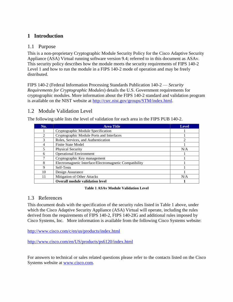
1.2 Module Validation Level
The following table lists the level of validation for each area in the FIPS PUB 140-2.
No. Area Title Level
1 Cryptographic Module Specification 1
2 Cryptographic Module Ports and Interfaces 1
3 Roles, Services, and Authentication 2
4 Finite State Model 1
5 Physical Security N/A
6 Operational Environment 1
7 Cryptographic Key management 1
8 Electromagnetic Interface/Electromagnetic Compatibility 1
9 Self-Tests 1
10 Design Assurance 1
11 Mitigation of Other Attacks N/A
Overall module validation level 1
Table 1 ASAv Module Validation Level
1.3 References
This document deals with the specification of the security rules listed in Table 1 above, under
which the Cisco Adaptive Security Appliance (ASA) Virtual will operate, including the rules
derived from the requirements of FIPS 140-2, FIPS 140-2IG and additional rules imposed by
Cisco Systems, Inc. More information is available from the following Cisco Systems website:
http://www.cisco.com/c/en/us/products/index.html
http://www.cisco.com/en/US/products/ps6120/index.html
For answers to technical or sales related questions please refer to the contacts listed on the Cisco
Systems website at www.cisco.com.
© Copyright 2016 Cisco Systems, Inc. 4 This document may be freely reproduced and distributed whole and intact including this Copyright Notice.
The NIST Validated Modules website (http://csrc.nist.gov/groups/STM/cmvp/validation.html)
contains contact information for answers to technical or sales-related questions for the module.
1.4 Terminology
In this document, the Cisco Adaptive Security Appliance (ASA) Virtual model identified is
referred to as ASA virtual, ASAv, virtual, module or the system.
1.5 Document Organization
The Security Policy document is part of the FIPS 140-2 Submission Package. In addition to this
document, the Submission Package contains:
Vendor Evidence document
Finite State Machine
Other supporting documentation as additional references
This document provides an overview of the Cisco Adaptive Security Appliance (ASA) Virtual
identified in section 1.2 above and explains the secure configuration and operation of the
module. This introduction section is followed by Section 2, which details the general features
and functionality of the module. Section 3 specifically addresses the required configuration for
the FIPS-mode of operation.
With the exception of this Non-Proprietary Security Policy, the FIPS 140-2 Validation
Submission Documentation is Cisco-proprietary and is releasable only under appropriate non-
disclosure agreements. For access to these documents, please contact Cisco Systems.
© Copyright 2016 Cisco Systems, Inc. 5 This document may be freely reproduced and distributed whole and intact including this Copyright Notice.
2 Cisco Adaptive Security Appliance (ASA) Virtual
Cisco® Adaptive Security Appliance (ASA) Virtual Series Next-Generation Firewalls provides
balanced security effectiveness with productivity. This solution offers the combination of the
industry's most deployed stateful firewall with a comprehensive range of next-generation
network security services, intrusion prevention system (IPS), content security, secure unified
communications, TLSv1, SSHv2, IKEv2, Remote Access VPN [With TLSv1/ DTLSv1 and
IKEv2/ ESPv3] and Suite B, all running in a virtual environment.
The Cisco ASAv delivers enterprise-class security for business-to-enterprise networks in a
virtual environment.
2.1 Cisco Servers
Cisco Adaptive Security Appliance (ASA) Virtual runs on many different UCS servers with the
VMware vSphere ESXi hypervisor version 5.1 (vendor affirmed) and version 5.5, providing pass
through data between the host platform and the module.
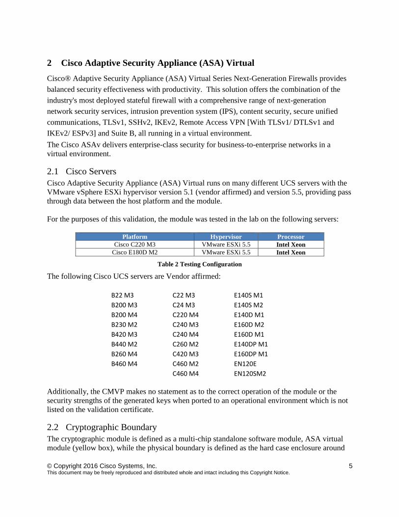
For the purposes of this validation, the module was tested in the lab on the following servers:
Platform Hypervisor Processor
Cisco C220 M3 VMware ESXi 5.5 Intel Xeon
Cisco E180D M2 VMware ESXi 5.5 Intel Xeon
Table 2 Testing Configuration
The following Cisco UCS servers are Vendor affirmed:
B22 M3 C22 M3 E140S M1
B200 M3 C24 M3 E140S M2
B200 M4 C220 M4 E140D M1
B230 M2 C240 M3 E160D M2
B420 M3 C240 M4 E160D M1
B440 M2 C260 M2 E140DP M1
B260 M4 C420 M3 E160DP M1
B460 M4 C460 M2 EN120E
C460 M4 EN120SM2
Additionally, the CMVP makes no statement as to the correct operation of the module or the
security strengths of the generated keys when ported to an operational environment which is not
listed on the validation certificate.
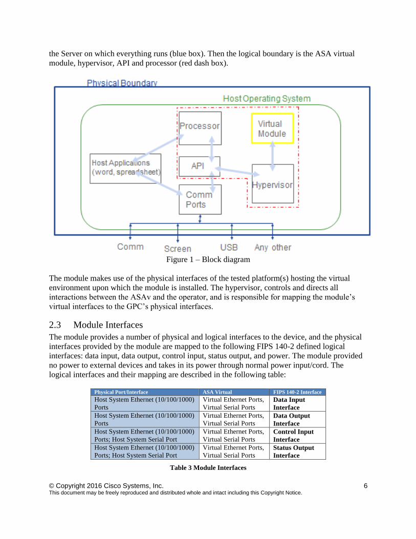
2.2 Cryptographic Boundary
The cryptographic module is defined as a multi-chip standalone software module, ASA virtual
module (yellow box), while the physical boundary is defined as the hard case enclosure around
© Copyright 2016 Cisco Systems, Inc. 6 This document may be freely reproduced and distributed whole and intact including this Copyright Notice.
the Server on which everything runs (blue box). Then the logical boundary is the ASA virtual
module, hypervisor, API and processor (red dash box).
Figure 1 – Block diagram
The module makes use of the physical interfaces of the tested platform(s) hosting the virtual
environment upon which the module is installed. The hypervisor, controls and directs all
interactions between the ASAv and the operator, and is responsible for mapping the module’s
virtual interfaces to the GPC’s physical interfaces.
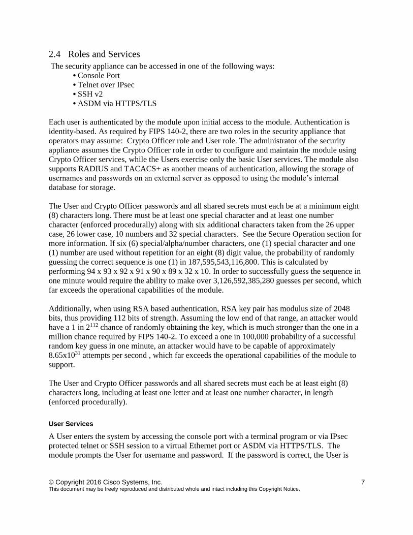
2.3 Module Interfaces
The module provides a number of physical and logical interfaces to the device, and the physical
interfaces provided by the module are mapped to the following FIPS 140-2 defined logical
interfaces: data input, data output, control input, status output, and power. The module provided
no power to external devices and takes in its power through normal power input/cord. The
logical interfaces and their mapping are described in the following table:
Physical Port/Interface ASA Virtual FIPS 140-2 Interface
Host System Ethernet (10/100/1000)
Ports
Virtual Ethernet Ports,
Virtual Serial Ports Data Input
Interface
Host System Ethernet (10/100/1000)
Ports
Virtual Ethernet Ports,
Virtual Serial Ports Data Output
Interface
Host System Ethernet (10/100/1000)
Ports; Host System Serial Port
Virtual Ethernet Ports,
Virtual Serial Ports Control Input
Interface
Host System Ethernet (10/100/1000)
Ports; Host System Serial Port
Virtual Ethernet Ports,
Virtual Serial Ports Status Output
Interface
Table 3 Module Interfaces
© Copyright 2016 Cisco Systems, Inc. 7 This document may be freely reproduced and distributed whole and intact including this Copyright Notice.
2.4 Roles and Services
The security appliance can be accessed in one of the following ways:
• Console Port
• Telnet over IPsec
• SSH v2
• ASDM via HTTPS/TLS
Each user is authenticated by the module upon initial access to the module. Authentication is
identity-based. As required by FIPS 140-2, there are two roles in the security appliance that
operators may assume: Crypto Officer role and User role. The administrator of the security
appliance assumes the Crypto Officer role in order to configure and maintain the module using
Crypto Officer services, while the Users exercise only the basic User services. The module also
supports RADIUS and TACACS+ as another means of authentication, allowing the storage of
usernames and passwords on an external server as opposed to using the module’s internal
database for storage.
The User and Crypto Officer passwords and all shared secrets must each be at a minimum eight
(8) characters long. There must be at least one special character and at least one number
character (enforced procedurally) along with six additional characters taken from the 26 upper
case, 26 lower case, 10 numbers and 32 special characters. See the Secure Operation section for
more information. If six (6) special/alpha/number characters, one (1) special character and one
(1) number are used without repetition for an eight (8) digit value, the probability of randomly
guessing the correct sequence is one (1) in 187,595,543,116,800. This is calculated by
performing 94 x 93 x 92 x 91 x 90 x 89 x 32 x 10. In order to successfully guess the sequence in
one minute would require the ability to make over 3,126,592,385,280 guesses per second, which
far exceeds the operational capabilities of the module.
Additionally, when using RSA based authentication, RSA key pair has modulus size of 2048
bits, thus providing 112 bits of strength. Assuming the low end of that range, an attacker would
have a 1 in 2112 chance of randomly obtaining the key, which is much stronger than the one in a
million chance required by FIPS 140-2. To exceed a one in 100,000 probability of a successful
random key guess in one minute, an attacker would have to be capable of approximately
8.65x1031 attempts per second , which far exceeds the operational capabilities of the module to
support.
The User and Crypto Officer passwords and all shared secrets must each be at least eight (8)
characters long, including at least one letter and at least one number character, in length
(enforced procedurally).
User Services
A User enters the system by accessing the console port with a terminal program or via IPsec
protected telnet or SSH session to a virtual Ethernet port or ASDM via HTTPS/TLS. The
module prompts the User for username and password. If the password is correct, the User is
© Copyright 2016 Cisco Systems, Inc. 8 This document may be freely reproduced and distributed whole and intact including this Copyright Notice.
allowed entry to the module management functionality. The other means of accessing the
console is via an IPsec session. This session is authenticated either using a shared secret or RSA
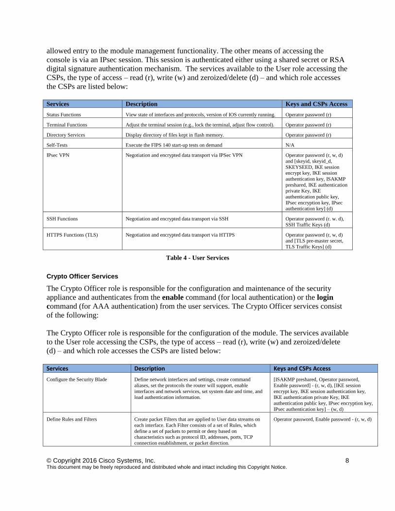
digital signature authentication mechanism. The services available to the User role accessing the
CSPs, the type of access – read (r), write (w) and zeroized/delete (d) – and which role accesses
the CSPs are listed below:
Services Description Keys and CSPs Access
Status Functions View state of interfaces and protocols, version of IOS currently running. Operator password (r)
Terminal Functions Adjust the terminal session (e.g., lock the terminal, adjust flow control). Operator password (r)
Directory Services Display directory of files kept in flash memory. Operator password (r)
Self-Tests Execute the FIPS 140 start-up tests on demand N/A
IPsec VPN Negotiation and encrypted data transport via IPSec VPN Operator password (r, w, d)
and [skeyid, skeyid_d,
SKEYSEED, IKE session encrypt key, IKE session
authentication key, ISAKMP
preshared, IKE authentication private Key, IKE
authentication public key,
IPsec encryption key, IPsec authentication key] (d)
SSH Functions Negotiation and encrypted data transport via SSH Operator password (r. w. d),
SSH Traffic Keys (d)
HTTPS Functions (TLS) Negotiation and encrypted data transport via HTTPS Operator password (r, w, d) and [TLS pre-master secret,
TLS Traffic Keys] (d)
Table 4 - User Services
Crypto Officer Services
The Crypto Officer role is responsible for the configuration and maintenance of the security
appliance and authenticates from the enable command (for local authentication) or the login
command (for AAA authentication) from the user services. The Crypto Officer services consist
of the following:
The Crypto Officer role is responsible for the configuration of the module. The services available
to the User role accessing the CSPs, the type of access – read (r), write (w) and zeroized/delete
(d) – and which role accesses the CSPs are listed below:
Services Description Keys and CSPs Access
Configure the Security Blade Define network interfaces and settings, create command
aliases, set the protocols the router will support, enable
interfaces and network services, set system date and time, and load authentication information.
[ISAKMP preshared, Operator password,
Enable password] - (r, w, d), [IKE session
encrypt key, IKE session authentication key, IKE authentication private Key, IKE
authentication public key, IPsec encryption key,
IPsec authentication key] – (w, d)
Define Rules and Filters Create packet Filters that are applied to User data streams on
each interface. Each Filter consists of a set of Rules, which
define a set of packets to permit or deny based on characteristics such as protocol ID, addresses, ports, TCP
connection establishment, or packet direction.
Operator password, Enable password - (r, w, d)
© Copyright 2016 Cisco Systems, Inc. 9 This document may be freely reproduced and distributed whole and intact including this Copyright Notice.
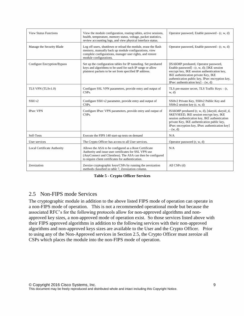
View Status Functions View the module configuration, routing tables, active sessions,
health, temperature, memory status, voltage, packet statistics, review accounting logs, and view physical interface status.
Operator password, Enable password - (r, w, d)
Manage the Security Blade Log off users, shutdown or reload the module, erase the flash
memory, manually back up module configurations, view
complete configurations, manager user rights, and restore module configurations.
Operator password, Enable password - (r, w, d)
Configure Encryption/Bypass Set up the configuration tables for IP tunneling. Set preshared
keys and algorithms to be used for each IP range or allow plaintext packets to be set from specified IP address.
[ISAKMP preshared, Operator password,
Enable password] - (r, w, d); [IKE session encrypt key, IKE session authentication key,
IKE authentication private Key, IKE
authentication public key, IPsec encryption key, IPsec authentication key] – (w, d)
TLS VPN (TLSv1.0)
Configure SSL VPN parameters, provide entry and output of
CSPs.
TLS pre-master secret, TLS Traffic Keys – (r,
w, d)
SSH v2 Configure SSH v2 parameter, provide entry and output of CSPs.
SSHv2 Private Key, SSHv2 Public Key and SSHv2 session key (r, w, d)
IPsec VPN Configure IPsec VPN parameters, provide entry and output of
CSPs.
ISAKMP preshared (r, w, d), [skeyid, skeyid_d,
SKEYSEED, IKE session encrypt key, IKE
session authentication key, IKE authentication private Key, IKE authentication public key,
IPsec encryption key, IPsec authentication key]
– (w, d)
Self-Tests Execute the FIPS 140 start-up tests on demand N/A
User services The Crypto Officer has access to all User services. Operator password (r, w, d)
Local Certificate Authority
Allows the ASA to be configured as a Root Certificate
Authority and issue user certificates for SSL VPN use (AnyConnect and Clientless). The ASA can then be configured
to require client certificates for authentication.
N/A
Zeroization Zeroize cryptographic keys/CSPs by running the zeroization
methods classified in table 7, Zeroization column.
All CSPs (d)
Table 5 - Crypto Officer Services
2.5 Non-FIPS mode Services
The cryptographic module in addition to the above listed FIPS mode of operation can operate in
a non-FIPS mode of operation. This is not a recommended operational mode but because the
associated RFC’s for the following protocols allow for non-approved algorithms and non-
approved key sizes, a non-approved mode of operation exist. So those services listed above with
their FIPS approved algorithms in addition to the following services with their non-approved
algorithms and non-approved keys sizes are available to the User and the Crypto Officer. Prior
to using any of the Non-Approved services in Section 2.5, the Crypto Officer must zeroize all
CSPs which places the module into the non-FIPS mode of operation.
© Copyright 2016 Cisco Systems, Inc. 10 This document may be freely reproduced and distributed whole and intact including this Copyright Notice.
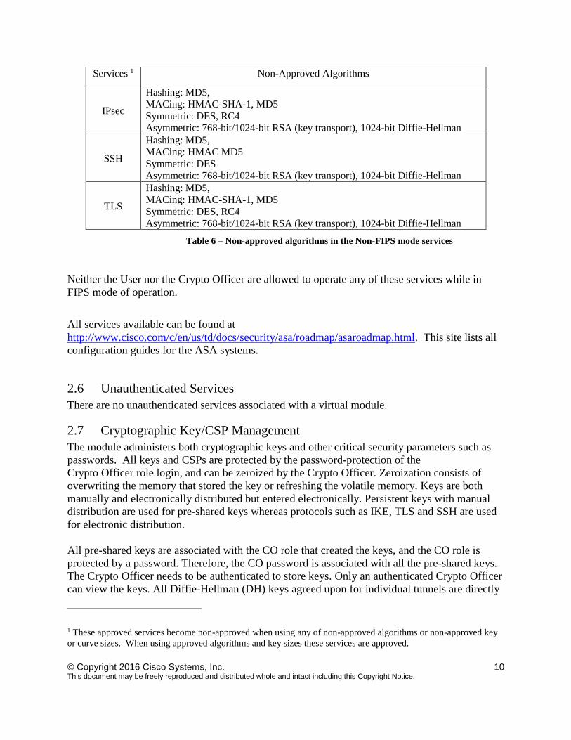
Services 1 Non-Approved Algorithms
IPsec
Hashing: MD5,
MACing: HMAC-SHA-1, MD5
Symmetric: DES, RC4
Asymmetric: 768-bit/1024-bit RSA (key transport), 1024-bit Diffie-Hellman
SSH
Hashing: MD5,
MACing: HMAC MD5
Symmetric: DES
Asymmetric: 768-bit/1024-bit RSA (key transport), 1024-bit Diffie-Hellman
TLS
Hashing: MD5,
MACing: HMAC-SHA-1, MD5
Symmetric: DES, RC4
Asymmetric: 768-bit/1024-bit RSA (key transport), 1024-bit Diffie-Hellman
Table 6 – Non-approved algorithms in the Non-FIPS mode services
Neither the User nor the Crypto Officer are allowed to operate any of these services while in
FIPS mode of operation.
All services available can be found at
http://www.cisco.com/c/en/us/td/docs/security/asa/roadmap/asaroadmap.html. This site lists all
configuration guides for the ASA systems.
2.6 Unauthenticated Services
There are no unauthenticated services associated with a virtual module.
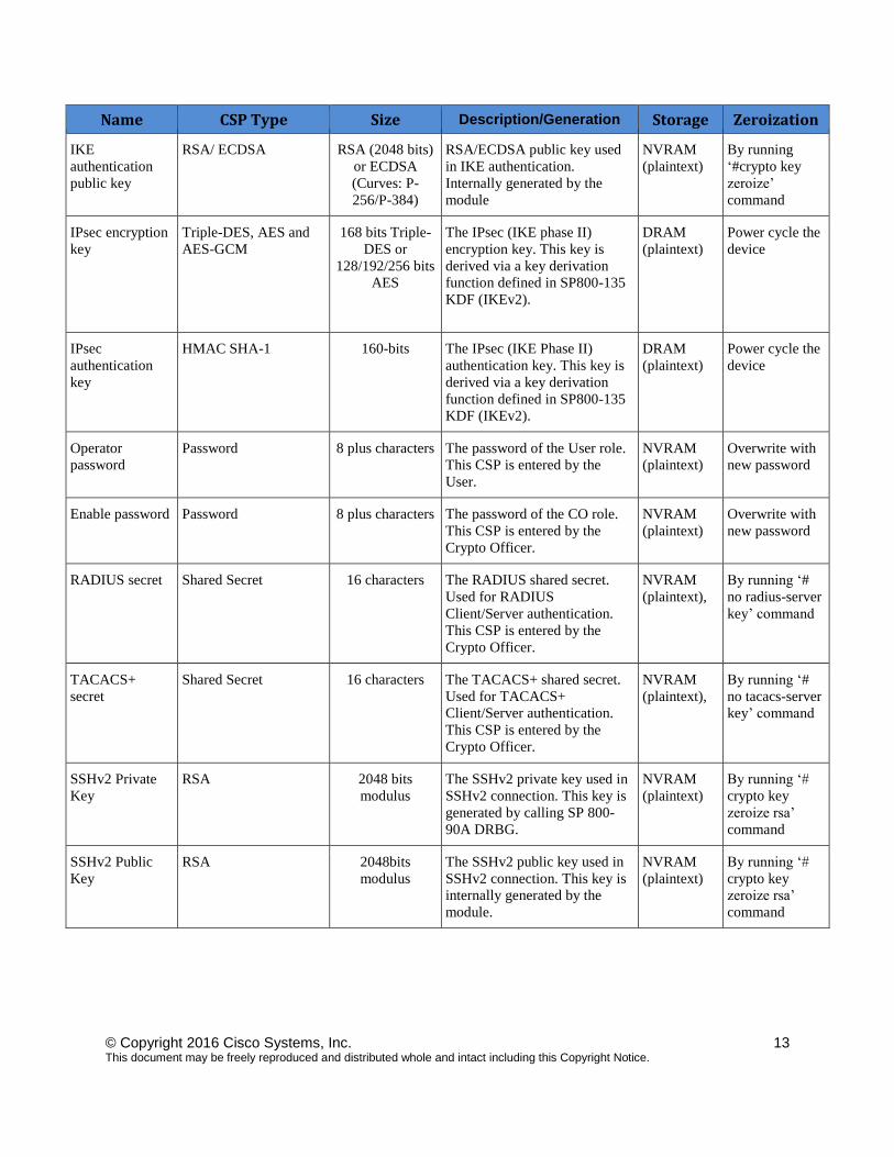
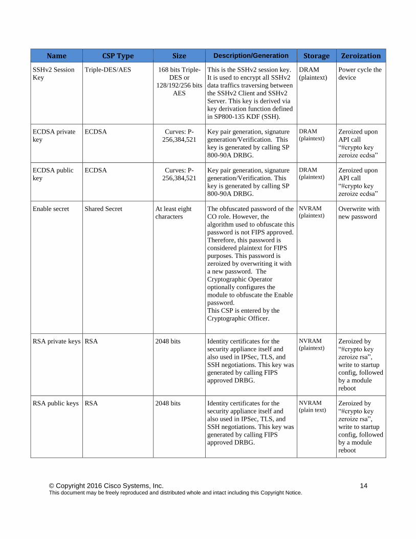
2.7 Cryptographic Key/CSP Management
The module administers both cryptographic keys and other critical security parameters such as
passwords. All keys and CSPs are protected by the password-protection of the
Crypto Officer role login, and can be zeroized by the Crypto Officer. Zeroization consists of
overwriting the memory that stored the key or refreshing the volatile memory. Keys are both
manually and electronically distributed but entered electronically. Persistent keys with manual
distribution are used for pre-shared keys whereas protocols such as IKE, TLS and SSH are used
for electronic distribution.
All pre-shared keys are associated with the CO role that created the keys, and the CO role is
protected by a password. Therefore, the CO password is associated with all the pre-shared keys.
The Crypto Officer needs to be authenticated to store keys. Only an authenticated Crypto Officer
can view the keys. All Diffie-Hellman (DH) keys agreed upon for individual tunnels are directly
1 These approved services become non-approved when using any of non-approved algorithms or non-approved key
or curve sizes. When using approved algorithms and key sizes these services are approved.
© Copyright 2016 Cisco Systems, Inc. 11 This document may be freely reproduced and distributed whole and intact including this Copyright Notice.
associated with that specific tunnel only via the IKE protocol. RSA Public keys are entered into
the module using digital certificates which contain relevant data such as the name of the public
key's owner, which associates the key with the correct entity. All other keys are associated with
the User role that entered them.
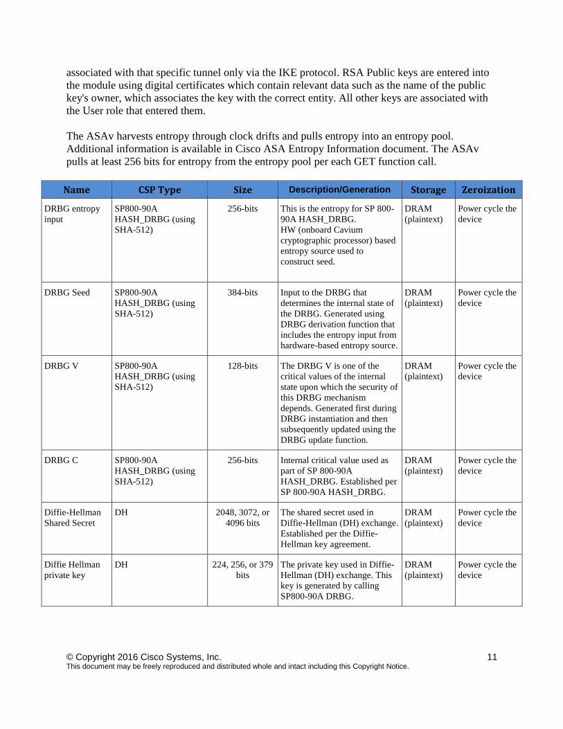
The ASAv harvests entropy through clock drifts and pulls entropy into an entropy pool.
Additional information is available in Cisco ASA Entropy Information document. The ASAv
pulls at least 256 bits for entropy from the entropy pool per each GET function call.
Name CSP Type Size Description/Generation Storage Zeroization
DRBG entropy
input
SP800-90A
HASH_DRBG (using
SHA-512)
256-bits This is the entropy for SP 800-
90A HASH_DRBG.
HW (onboard Cavium
cryptographic processor) based
entropy source used to
construct seed.
DRAM
(plaintext)
Power cycle the
device
DRBG Seed SP800-90A
HASH_DRBG (using
SHA-512)
384-bits Input to the DRBG that
determines the internal state of
the DRBG. Generated using
DRBG derivation function that
includes the entropy input from
hardware-based entropy source.
DRAM
(plaintext)
Power cycle the
device
DRBG V SP800-90A
HASH_DRBG (using
SHA-512)
128-bits The DRBG V is one of the
critical values of the internal
state upon which the security of
this DRBG mechanism
depends. Generated first during
DRBG instantiation and then
subsequently updated using the
DRBG update function.
DRAM
(plaintext)
Power cycle the
device
DRBG C SP800-90A
HASH_DRBG (using
SHA-512)
256-bits Internal critical value used as
part of SP 800-90A
HASH_DRBG. Established per
SP 800-90A HASH_DRBG.
DRAM
(plaintext)
Power cycle the
device
Diffie-Hellman
Shared Secret
DH
2048, 3072, or
4096 bits
The shared secret used in
Diffie-Hellman (DH) exchange.
Established per the Diffie-
Hellman key agreement.
DRAM
(plaintext)
Power cycle the
device
Diffie Hellman
private key
DH
224, 256, or 379
bits
The private key used in Diffie-
Hellman (DH) exchange. This
key is generated by calling
SP800-90A DRBG.
DRAM
(plaintext)
Power cycle the
device
© Copyright 2016 Cisco Systems, Inc. 12 This document may be freely reproduced and distributed whole and intact including this Copyright Notice.
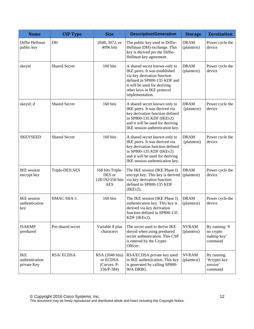
Name CSP Type Size Description/Generation Storage Zeroization
Diffie Hellman
public key
DH
2048, 3072, or
4096 bits
The public key used in Diffie-
Hellman (DH) exchange. This
key is derived per the Diffie-
Hellman key agreement.
DRAM
(plaintext)
Power cycle the
device
skeyid Shared Secret 160 bits A shared secret known only to
IKE peers. It was established
via key derivation function
defined in SP800-135 KDF and
it will be used for deriving
other keys in IKE protocol
implementation.
DRAM
(plaintext)
Power cycle the
device
skeyid_d Shared Secret 160 bits A shared secret known only to
IKE peers. It was derived via
key derivation function defined
in SP800-135 KDF (IKEv2)
and it will be used for deriving
IKE session authentication key.
DRAM
(plaintext)
Power cycle the
device
SKEYSEED Shared Secret 160 bits A shared secret known only to
IKE peers. It was derived via
key derivation function defined
in SP800-135 KDF (IKEv2)
and it will be used for deriving
IKE session authentication key.
DRAM
(plaintext)
Power cycle the
device
IKE session
encrypt key
Triple-DES/AES 168 bits Triple-
DES or
128/192/256 bits
AES
The IKE session (IKE Phase I)
encrypt key. This key is derived
via key derivation function
defined in SP800-135 KDF
(IKEv2).
DRAM
(plaintext)
Power cycle the
device
IKE session
authentication
key
HMAC SHA-1
160 bits The IKE session (IKE Phase I)
authentication key. This key is
derived via key derivation
function defined in SP800-135
KDF (IKEv2).
DRAM
(plaintext)
Power cycle the
device
ISAKMP
preshared
Pre-shared secret Variable 8 plus
characters
The secret used to derive IKE
skeyid when using preshared
secret authentication. This CSP
is entered by the Crypto
Officer.
NVRAM
(plaintext)
By running ‘#
no crypto
isakmp key’
command
IKE
authentication
private Key
RSA/ ECDSA
RSA (2048 bits)
or ECDSA
(Curves: P-
256/P-384)
RSA/ECDSA private key used
in IKE authentication. This key
is generated by calling SP800-
90A DRBG.
NVRAM
(plaintext)
By running
‘#crypto key
zeroize’
command
© Copyright 2016 Cisco Systems, Inc. 13 This document may be freely reproduced and distributed whole and intact including this Copyright Notice.
Name CSP Type Size Description/Generation Storage Zeroization
IKE
authentication
public key
RSA/ ECDSA
RSA (2048 bits)
or ECDSA
(Curves: P-
256/P-384)
RSA/ECDSA public key used
in IKE authentication.
Internally generated by the
module
NVRAM
(plaintext)
By running
‘#crypto key
zeroize’
command
IPsec encryption
key
Triple-DES, AES and
AES-GCM
168 bits Triple-
DES or
128/192/256 bits
AES
The IPsec (IKE phase II)
encryption key. This key is
derived via a key derivation
function defined in SP800-135
KDF (IKEv2).
DRAM
(plaintext)
Power cycle the
device
IPsec
authentication
key
HMAC SHA-1
160-bits The IPsec (IKE Phase II)
authentication key. This key is
derived via a key derivation
function defined in SP800-135
KDF (IKEv2).
DRAM
(plaintext)
Power cycle the
device
Operator
password
Password 8 plus characters The password of the User role.
This CSP is entered by the
User.
NVRAM
(plaintext)
Overwrite with
new password
Enable password Password 8 plus characters The password of the CO role.
This CSP is entered by the
Crypto Officer.
NVRAM
(plaintext)
Overwrite with
new password
RADIUS secret Shared Secret
16 characters The RADIUS shared secret.
Used for RADIUS
Client/Server authentication.
This CSP is entered by the
Crypto Officer.
NVRAM
(plaintext),
By running ‘#
no radius-server
key’ command
TACACS+
secret
Shared Secret
16 characters The TACACS+ shared secret.
Used for TACACS+
Client/Server authentication.
This CSP is entered by the
Crypto Officer.
NVRAM
(plaintext),
By running ‘#
no tacacs-server
key’ command
SSHv2 Private
Key
RSA
2048 bits
modulus
The SSHv2 private key used in
SSHv2 connection. This key is
generated by calling SP 800-
90A DRBG.
NVRAM
(plaintext)
By running ‘#
crypto key
zeroize rsa’
command
SSHv2 Public
Key
RSA
2048bits
modulus
The SSHv2 public key used in
SSHv2 connection. This key is
internally generated by the
module.
NVRAM
(plaintext)
By running ‘#
crypto key
zeroize rsa’
command
© Copyright 2016 Cisco Systems, Inc. 14 This document may be freely reproduced and distributed whole and intact including this Copyright Notice.
Name CSP Type Size Description/Generation Storage Zeroization
SSHv2 Session
Key
Triple-DES/AES 168 bits Triple-
DES or
128/192/256 bits
AES
This is the SSHv2 session key.
It is used to encrypt all SSHv2
data traffics traversing between
the SSHv2 Client and SSHv2
Server. This key is derived via
key derivation function defined
in SP800-135 KDF (SSH).
DRAM
(plaintext)
Power cycle the
device
ECDSA private
key
ECDSA
Curves: P-
256,384,521
Key pair generation, signature
generation/Verification. This
key is generated by calling SP
800-90A DRBG.
DRAM
(plaintext) Zeroized upon
API call
“#crypto key
zeroize ecdsa”
ECDSA public
key
ECDSA
Curves: P-
256,384,521
Key pair generation, signature
generation/Verification. This
key is generated by calling SP
800-90A DRBG.
DRAM
(plaintext) Zeroized upon
API call
“#crypto key
zeroize ecdsa”
Enable secret Shared Secret At least eight
characters
The obfuscated password of the
CO role. However, the
algorithm used to obfuscate this
password is not FIPS approved.
Therefore, this password is
considered plaintext for FIPS
purposes. This password is
zeroized by overwriting it with
a new password. The
Cryptographic Operator
optionally configures the
module to obfuscate the Enable
password.
This CSP is entered by the
Cryptographic Officer.
NVRAM
(plaintext) Overwrite with
new password
RSA private keys RSA 2048 bits Identity certificates for the
security appliance itself and
also used in IPSec, TLS, and
SSH negotiations. This key was
generated by calling FIPS
approved DRBG.
NVRAM
(plaintext) Zeroized by
“#crypto key
zeroize rsa”,
write to startup
config, followed
by a module
reboot
RSA public keys RSA 2048 bits Identity certificates for the
security appliance itself and
also used in IPSec, TLS, and
SSH negotiations. This key was
generated by calling FIPS
approved DRBG.
NVRAM
(plain text) Zeroized by
“#crypto key
zeroize rsa”,
write to startup
config, followed
by a module
reboot
© Copyright 2016 Cisco Systems, Inc. 15 This document may be freely reproduced and distributed whole and intact including this Copyright Notice.
Name CSP Type Size Description/Generation Storage Zeroization
TLS pre-master
secret
Shared Secret At least eight
characters
Shared secret created/derived
using asymmetric cryptography
from which new HTTPS
session keys can be created.
This key entered into the
module in cipher text form,
encrypted by RSA public key.
DRAM
(plaintext)
Automatically
when TLS
session is
terminated.
TLS traffic keys Triple-DES/AES
128/192/256
HMAC-
SHA1/256/384/512
168 bits Triple-
DES or
128/192/256 bits
AES
Used in HTTPS connections.
Generated using TLS protocol.
This key was derived in the
module.
DRAM
(plain text)
Automatically
when TLS
session is
terminated
Integrity test key RSA-2048 Public key 2048 bits A hard coded key used for
software power-up/load
integrity verification.
Hard coded
for Software
integrity
testing
Zeroized by
“#erase flash:”
command (or
replacing), write
to startup config,
followed by a
module reboot
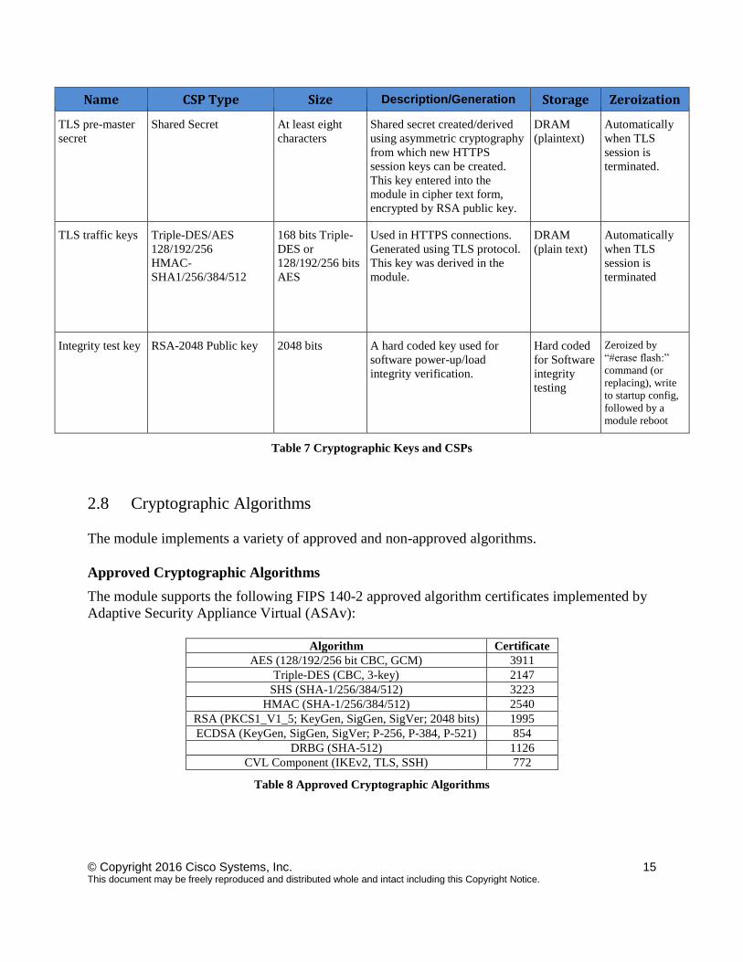
Table 7 Cryptographic Keys and CSPs
2.8 Cryptographic Algorithms
The module implements a variety of approved and non-approved algorithms.
Approved Cryptographic Algorithms
The module supports the following FIPS 140-2 approved algorithm certificates implemented by
Adaptive Security Appliance Virtual (ASAv):
Algorithm Certificate
AES (128/192/256 bit CBC, GCM) 3911
Triple-DES (CBC, 3-key) 2147
SHS (SHA-1/256/384/512) 3223
HMAC (SHA-1/256/384/512) 2540
RSA (PKCS1_V1_5; KeyGen, SigGen, SigVer; 2048 bits) 1995
ECDSA (KeyGen, SigGen, SigVer; P-256, P-384, P-521) 854
DRBG (SHA-512) 1126
CVL Component (IKEv2, TLS, SSH) 772
Table 8 Approved Cryptographic Algorithms
© Copyright 2016 Cisco Systems, Inc. 16 This document may be freely reproduced and distributed whole and intact including this Copyright Notice.
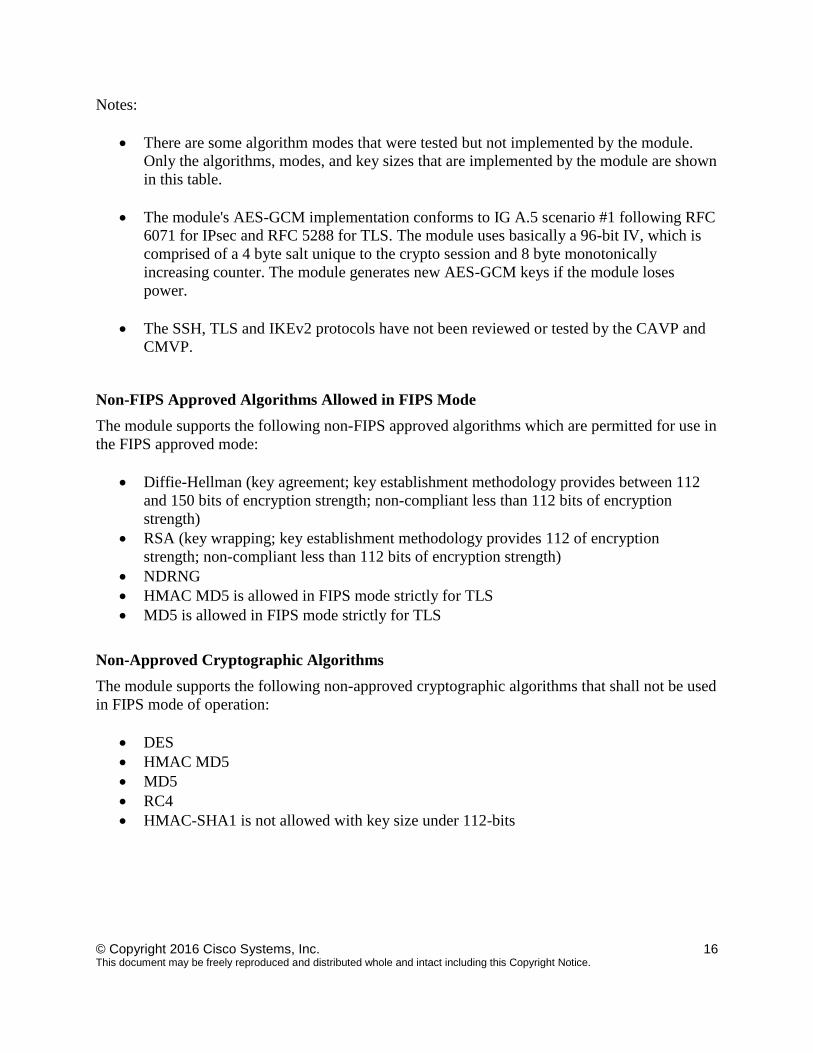
Notes:
There are some algorithm modes that were tested but not implemented by the module.
Only the algorithms, modes, and key sizes that are implemented by the module are shown
in this table.
The module's AES-GCM implementation conforms to IG A.5 scenario #1 following RFC
6071 for IPsec and RFC 5288 for TLS. The module uses basically a 96-bit IV, which is
comprised of a 4 byte salt unique to the crypto session and 8 byte monotonically
increasing counter. The module generates new AES-GCM keys if the module loses
power.
The SSH, TLS and IKEv2 protocols have not been reviewed or tested by the CAVP and
CMVP.
Non-FIPS Approved Algorithms Allowed in FIPS Mode
The module supports the following non-FIPS approved algorithms which are permitted for use in
the FIPS approved mode:
Diffie-Hellman (key agreement; key establishment methodology provides between 112
and 150 bits of encryption strength; non-compliant less than 112 bits of encryption
strength)
RSA (key wrapping; key establishment methodology provides 112 of encryption
strength; non-compliant less than 112 bits of encryption strength)
NDRNG
HMAC MD5 is allowed in FIPS mode strictly for TLS
MD5 is allowed in FIPS mode strictly for TLS
Non-Approved Cryptographic Algorithms
The module supports the following non-approved cryptographic algorithms that shall not be used
in FIPS mode of operation:
DES
HMAC MD5
MD5
RC4
HMAC-SHA1 is not allowed with key size under 112-bits
© Copyright 2016 Cisco Systems, Inc. 17 This document may be freely reproduced and distributed whole and intact including this Copyright Notice.
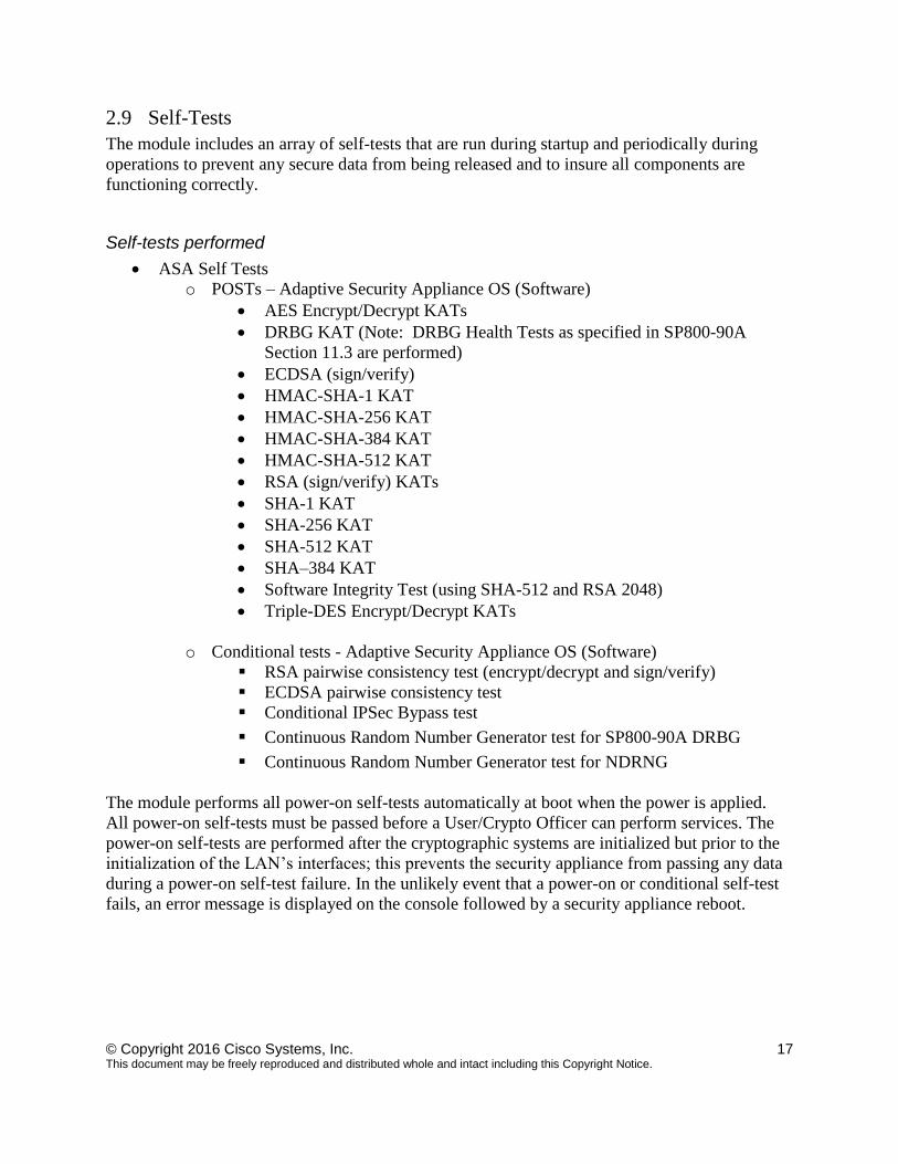
2.9 Self-Tests
The module includes an array of self-tests that are run during startup and periodically during
operations to prevent any secure data from being released and to insure all components are
functioning correctly.
Self-tests performed
ASA Self Tests
o POSTs – Adaptive Security Appliance OS (Software)
AES Encrypt/Decrypt KATs
DRBG KAT (Note: DRBG Health Tests as specified in SP800-90A
Section 11.3 are performed)
ECDSA (sign/verify)
HMAC-SHA-1 KAT
HMAC-SHA-256 KAT
HMAC-SHA-384 KAT
HMAC-SHA-512 KAT
RSA (sign/verify) KATs
SHA-1 KAT
SHA-256 KAT
SHA-512 KAT
SHA–384 KAT
Software Integrity Test (using SHA-512 and RSA 2048)
Triple-DES Encrypt/Decrypt KATs
o Conditional tests - Adaptive Security Appliance OS (Software)
RSA pairwise consistency test (encrypt/decrypt and sign/verify)
ECDSA pairwise consistency test
Conditional IPSec Bypass test
Continuous Random Number Generator test for SP800-90A DRBG
Continuous Random Number Generator test for NDRNG
The module performs all power-on self-tests automatically at boot when the power is applied.
All power-on self-tests must be passed before a User/Crypto Officer can perform services. The
power-on self-tests are performed after the cryptographic systems are initialized but prior to the
initialization of the LAN’s interfaces; this prevents the security appliance from passing any data
during a power-on self-test failure. In the unlikely event that a power-on or conditional self-test
fails, an error message is displayed on the console followed by a security appliance reboot.
© Copyright 2016 Cisco Systems, Inc. 18 This document may be freely reproduced and distributed whole and intact including this Copyright Notice.
3 Secure Operation
Initial install of the ASAv can be obtained in
http://www.cisco.com/c/en/us/td/docs/security/asa/asa94/asav/quick-start/asav-quick.pdf. The
module meets all the Level 1 requirements for FIPS 140-2. The module is shipped only to
authorized operators by the vendor, and the module is shipped in Cisco boxes with Cisco
adhesive. Follow the installation instructions found in the link above and the instructions
provided below to place the module in FIPS-approved mode. Operating this module without
maintaining the following settings will remove the module from the FIPS approved mode of
operation.
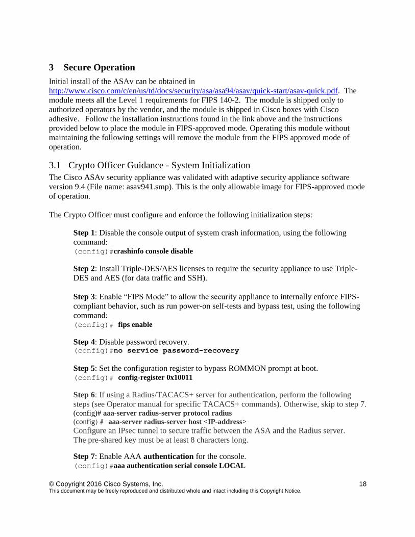
3.1 Crypto Officer Guidance - System Initialization
The Cisco ASAv security appliance was validated with adaptive security appliance software
version 9.4 (File name: asav941.smp). This is the only allowable image for FIPS-approved mode
of operation.
The Crypto Officer must configure and enforce the following initialization steps:
Step 1: Disable the console output of system crash information, using the following
command: (config)#crashinfo console disable
Step 2: Install Triple-DES/AES licenses to require the security appliance to use Triple-
DES and AES (for data traffic and SSH). Step 3: Enable “FIPS Mode” to allow the security appliance to internally enforce FIPS-
compliant behavior, such as run power-on self-tests and bypass test, using the following
command:
(config)# fips enable
Step 4: Disable password recovery. (config)#no service password-recovery
Step 5: Set the configuration register to bypass ROMMON prompt at boot. (config)# config-register 0x10011
Step 6: If using a Radius/TACACS+ server for authentication, perform the following
steps (see Operator manual for specific TACACS+ commands). Otherwise, skip to step 7. (config)# aaa-server radius-server protocol radius (config)# aaa-server radius-server host <IP-address>
Configure an IPsec tunnel to secure traffic between the ASA and the Radius server.
The pre-shared key must be at least 8 characters long.
Step 7: Enable AAA authentication for the console.
(config)#aaa authentication serial console LOCAL
© Copyright 2016 Cisco Systems, Inc. 19 This document may be freely reproduced and distributed whole and intact including this Copyright Notice.
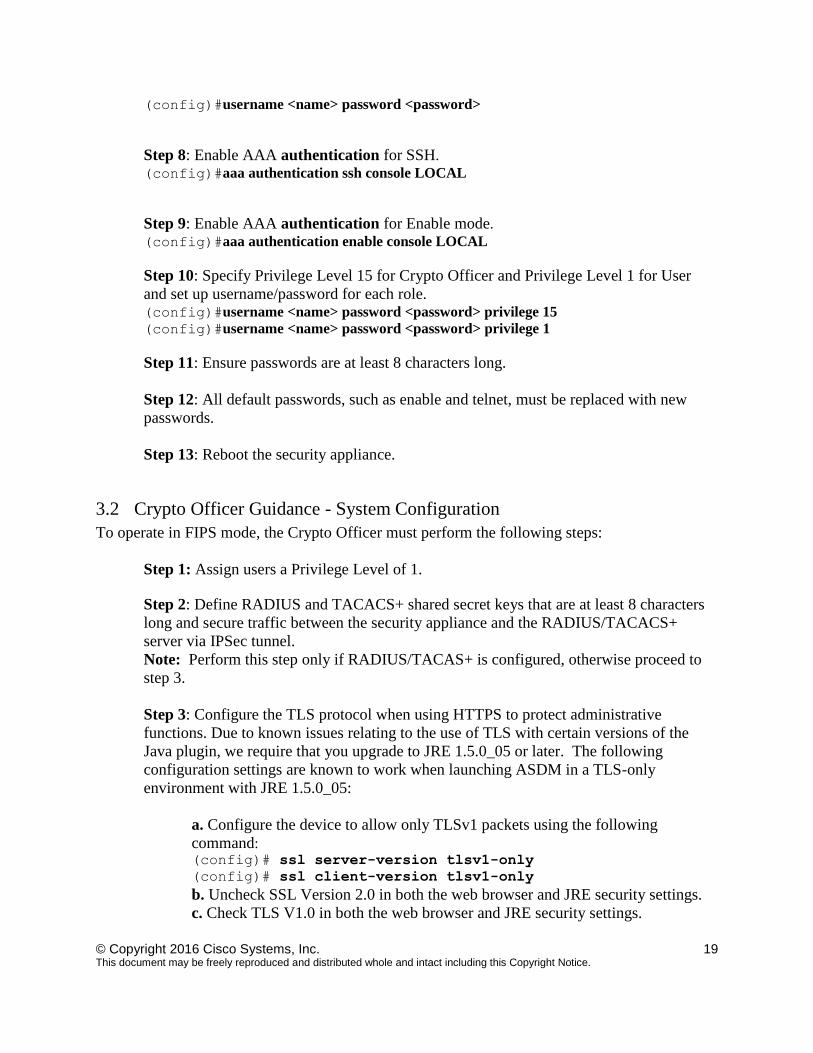
(config)#username <name> password <password>
Step 8: Enable AAA authentication for SSH.
(config)#aaa authentication ssh console LOCAL
Step 9: Enable AAA authentication for Enable mode.
(config)#aaa authentication enable console LOCAL
Step 10: Specify Privilege Level 15 for Crypto Officer and Privilege Level 1 for User
and set up username/password for each role. (config)#username <name> password <password> privilege 15
(config)#username <name> password <password> privilege 1
Step 11: Ensure passwords are at least 8 characters long.
Step 12: All default passwords, such as enable and telnet, must be replaced with new
passwords.
Step 13: Reboot the security appliance.
3.2 Crypto Officer Guidance - System Configuration
To operate in FIPS mode, the Crypto Officer must perform the following steps:
Step 1: Assign users a Privilege Level of 1.
Step 2: Define RADIUS and TACACS+ shared secret keys that are at least 8 characters
long and secure traffic between the security appliance and the RADIUS/TACACS+
server via IPSec tunnel. Note: Perform this step only if RADIUS/TACAS+ is configured, otherwise proceed to
step 3.
Step 3: Configure the TLS protocol when using HTTPS to protect administrative
functions. Due to known issues relating to the use of TLS with certain versions of the
Java plugin, we require that you upgrade to JRE 1.5.0_05 or later. The following
configuration settings are known to work when launching ASDM in a TLS-only
environment with JRE 1.5.0_05:
a. Configure the device to allow only TLSv1 packets using the following
command: (config)# ssl server-version tlsv1-only
(config)# ssl client-version tlsv1-only
b. Uncheck SSL Version 2.0 in both the web browser and JRE security settings.
c. Check TLS V1.0 in both the web browser and JRE security settings.
© Copyright 2016 Cisco Systems, Inc. 20 This document may be freely reproduced and distributed whole and intact including this Copyright Notice.
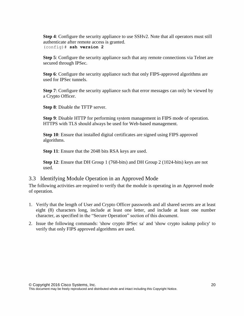
Step 4: Configure the security appliance to use SSHv2. Note that all operators must still
authenticate after remote access is granted. (config)# ssh version 2
Step 5: Configure the security appliance such that any remote connections via Telnet are
secured through IPSec.
Step 6: Configure the security appliance such that only FIPS-approved algorithms are
used for IPSec tunnels.
Step 7: Configure the security appliance such that error messages can only be viewed by
a Crypto Officer.
Step 8: Disable the TFTP server.
Step 9: Disable HTTP for performing system management in FIPS mode of operation.
HTTPS with TLS should always be used for Web-based management.
Step 10: Ensure that installed digital certificates are signed using FIPS approved
algorithms.
Step 11: Ensure that the 2048 bits RSA keys are used.
Step 12: Ensure that DH Group 1 (768-bits) and DH Group 2 (1024-bits) keys are not
used.
3.3 Identifying Module Operation in an Approved Mode
The following activities are required to verify that the module is operating in an Approved mode
of operation.
1. Verify that the length of User and Crypto Officer passwords and all shared secrets are at least
eight (8) characters long, include at least one letter, and include at least one number
character, as specified in the “Secure Operation” section of this document.
2. Issue the following commands: 'show crypto IPSec sa' and 'show crypto isakmp policy' to
verify that only FIPS approved algorithms are used.