cisco aci virtualization guide, release 1.1(1j) · cisco aci virtualization guide, release 1.1(1j)...
TRANSCRIPT
Cisco ACI Virtualization Guide, Release 1.1(1j)First Published: June 14, 2015
Last Modified: September 06, 2016
Americas HeadquartersCisco Systems, Inc.170 West Tasman DriveSan Jose, CA 95134-1706USAhttp://www.cisco.comTel: 408 526-4000 800 553-NETS (6387)Fax: 408 527-0883

THE SPECIFICATIONS AND INFORMATION REGARDING THE PRODUCTS IN THIS MANUAL ARE SUBJECT TO CHANGE WITHOUT NOTICE. ALL STATEMENTS,INFORMATION, AND RECOMMENDATIONS IN THIS MANUAL ARE BELIEVED TO BE ACCURATE BUT ARE PRESENTED WITHOUT WARRANTY OF ANY KIND,EXPRESS OR IMPLIED. USERS MUST TAKE FULL RESPONSIBILITY FOR THEIR APPLICATION OF ANY PRODUCTS.
THE SOFTWARE LICENSE AND LIMITEDWARRANTY FOR THE ACCOMPANYING PRODUCT ARE SET FORTH IN THE INFORMATION PACKET THAT SHIPPED WITHTHE PRODUCT AND ARE INCORPORATED HEREIN BY THIS REFERENCE. IF YOU ARE UNABLE TO LOCATE THE SOFTWARE LICENSE OR LIMITED WARRANTY,CONTACT YOUR CISCO REPRESENTATIVE FOR A COPY.
The Cisco implementation of TCP header compression is an adaptation of a program developed by the University of California, Berkeley (UCB) as part of UCB's public domain versionof the UNIX operating system. All rights reserved. Copyright © 1981, Regents of the University of California.
NOTWITHSTANDINGANYOTHERWARRANTYHEREIN, ALL DOCUMENT FILES AND SOFTWARE OF THESE SUPPLIERS ARE PROVIDED “AS IS"WITH ALL FAULTS.CISCO AND THE ABOVE-NAMED SUPPLIERS DISCLAIM ALL WARRANTIES, EXPRESSED OR IMPLIED, INCLUDING, WITHOUT LIMITATION, THOSE OFMERCHANTABILITY, FITNESS FORA PARTICULAR PURPOSEANDNONINFRINGEMENTORARISING FROMACOURSEOFDEALING, USAGE, OR TRADE PRACTICE.
IN NO EVENT SHALL CISCO OR ITS SUPPLIERS BE LIABLE FOR ANY INDIRECT, SPECIAL, CONSEQUENTIAL, OR INCIDENTAL DAMAGES, INCLUDING, WITHOUTLIMITATION, LOST PROFITS OR LOSS OR DAMAGE TO DATA ARISING OUT OF THE USE OR INABILITY TO USE THIS MANUAL, EVEN IF CISCO OR ITS SUPPLIERSHAVE BEEN ADVISED OF THE POSSIBILITY OF SUCH DAMAGES.
Any Internet Protocol (IP) addresses and phone numbers used in this document are not intended to be actual addresses and phone numbers. Any examples, command display output, networktopology diagrams, and other figures included in the document are shown for illustrative purposes only. Any use of actual IP addresses or phone numbers in illustrative content is unintentionaland coincidental.
Cisco and the Cisco logo are trademarks or registered trademarks of Cisco and/or its affiliates in the U.S. and other countries. To view a list of Cisco trademarks, go to this URL: http://www.cisco.com/go/trademarks. Third-party trademarks mentioned are the property of their respective owners. The use of the word partner does not imply a partnershiprelationship between Cisco and any other company. (1110R)
© 2015-2016 Cisco Systems, Inc. All rights reserved.
C O N T E N T S
P r e f a c e Preface xi
Audience xi
Document Conventions xi
Related Documentation xiii
Documentation Feedback xv
Obtaining Documentation and Submitting a Service Request xv
C H A P T E R 1 Cisco ACI Virtual Machine Networking 1
Cisco ACI VM Networking Supports Multiple Vendors' Virtual Machine Managers 1
Virtual Machine Manager Domain Main Components 2
Virtual Machine Manager Domains 3
VMM Domain VLAN Pool Association 4
VMM Domain EPG Association 5
Attachable Entity Profile 7
EPG Policy Resolution and Deployment Immediacy 8
Guidelines for Deleting VMM Domains 9
C H A P T E R 2 Cisco ACI with VMware VDS and VMware vShield Integration 11
Configuring Virtual Machine Networking Policies 11
APIC Supported VMware VDS Versions 11
Mapping ACI and VMware Constructs 12
VMware VDS Parameters Managed By APIC 12
VDS Parameters Managed by APIC 12
VDS Port Group Parameters Managed by APIC 13
vShield Manager Parameters Managed by APIC 13
Creating a VMM Domain Profile 14
GUI Tasks 14
Cisco ACI Virtualization Guide, Release 1.1(1j) iii
Prerequisites for Creating a VMM Domain Profile 14
vCenter Domain Operational Workflow 15
Creating a vCenter Domain Profile Using the GUI 16
vCenter and vShield Domain Operational Workflow 18
Creating a vCenter and vShield Domain Profile Using the GUI 20
Creating VDS Uplink Port Groups 22
Working with Blade Servers 22
Guidelines for Cisco UCS B-Series Servers 22
Setting up an Access Policy for a Blade Server Using the GUI 23
Troubleshooting the Cisco ACI and VMware VMM System Integration 25
Additional Reference Sections 25
Custom User Account with Minimum VMware vCenter Privileges 25
Quarantine Port Groups 25
On-Demand VMM Inventory Refresh 26
Guidelines for Migrating a vCenter Hypervisor VMK0 to an ACI Inband VLAN 26
Create the Necessary Management EPG Policies in APIC 26
Migrate the VMK0 to the Inband ACI VLAN 27
REST API Tasks 27
Creating a vCenter Domain Profile Using the REST API 27
Creating a vCenter and a vShield Domain Profile Using the REST API 29
Setting Up an Access Policy for a Blade Server Using the REST API 31
CLI Tasks 32
Creating a vCenter Domain Profile Using the CLI 32
Creating a vCenter and a vShield Domain Profile Using the CLI 35
C H A P T E R 3 Cisco ACI and Cisco AVS 41
Cisco AVS Overview 41
About the Cisco AVS and the VMware vCenter 43
Required Software 44
Cisco AVS Documentation 45
Installing the Cisco AVS 45
Prerequisites for Installing the Cisco AVS 45
Workflow for Installing the Cisco AVS 46
Creating Interface, Switch, and Center Domain Profiles 46
Interface and Switch Profile Guidelines and Prerequisites 47
Cisco ACI Virtualization Guide, Release 1.1(1j)iv
Contents
vCenter Domain Profile Guidelines and Prerequisites 48
Creating Interface and Switch Profiles and a vCenter Domain Profile Using the GUI 48
Completion of the Cisco AVS Installation in the VSUM 51
Prerequisites for Installing Cisco AVS 52
Installing Cisco AVS Using VSUM 52
Verifying the Cisco AVS Installation 53
Verifying the Virtual Switch Status 53
Verifying the vNIC Status 54
Key Post-Installation Configuration Tasks for the Cisco AVS 54
Prerequisites for Configuring the Cisco AVS 54
Workflow for Key Post-Installation Configuration Tasks for the Cisco AVS 54
Deploying an Application Profile for the Cisco AVS 56
Creating a Tenant, Private Network, and Bridge Domain Using the GUI 56
Creating an Application Profile Using the GUI 57
Creating EPGs Using the GUI 57
Assigning Port Groups to the VM in vCenter 58
Creating a Filter Using the GUI 58
Creating a Contract Using the GUI 59
Verifying the Application Profile 59
Verifying the Application Profile and EPGs in Cisco APIC 59
Verifying the EPGs in vCenter 60
Verifying that VMs can Communicate 60
Guidelines for Using VMotion with Cisco AVS 60
Distributed Firewall 61
Benefits of Distributed Firewall 62
Configuring Distributed Firewall 63
Workflow for Configuring Distributed Firewall 64
Creating a Distributed Firewall Policy or Changing its Mode Using the GUI 64
Configuring a Stateful Policy for Distributed Firewall 65
Enabling Distributed Firewall After Installation or Upgrade 66
Microsegmentation with Cisco AVS 67
Benefits of Microsegmentation with Cisco AVS 67
How Microsegmentation Using Cisco AVS Works 68
Attributes for Microsegmentation with Cisco AVS 69
Precedence of Attributes 70
Cisco ACI Virtualization Guide, Release 1.1(1j) v
Contents
Configuring Microsegmentation with Cisco AVS 72
Workflow for Configuring Microsegmentation with Cisco AVS 72
Configuring Microsegmentation with Cisco AVS to Isolate VMs Within an EPG 72
Configuring Microsegmentation with Cisco AVS in Different Base EPGs 75
REST API Tasks for Cisco AVS 78
Creating the Tenant, Private Network, and Bridge Domain Using the REST API 78
Deploying an Application Policy Using the REST API 79
Changing the Distributed Firewall Mode Using the REST API 81
Configuring a Stateful Policy for Distributed Firewall Using the REST API 81
CLI Tasks for Cisco AVS 82
Creating a Tenant, Private Network, and Bridge Domain Using the CLI 82
Deploying an Application Policy Using the CLI 83
C H A P T E R 4 Cisco ACI with Microsoft SCVMM 89
About Cisco ACI with Microsoft SCVMM 89
Cisco ACI with Microsoft SCVMM Solution Overview 89
Physical and Logical Topology of SCVMM 90
About the Mapping of ACI Constructs in SCVMM 90
Getting Started with Cisco ACI with Microsoft SCVMM 91
Prerequisites for Getting Started with Cisco ACI with Microsoft SCVMM 92
Installing, Setting Up, and Verifying the Cisco ACI with Microsoft SCVMM
Components 92
Installing the APIC SCVMM Agent on SCVMM 93
Configuring APIC IP Settings with APIC Credentials on the SCVMM Agent 94
Generating APIC Hyper-V Agent OpFlex Certificate 95
Adding the OpFlex Certificate Policy to APIC 96
Installing the APIC Hyper-V Agent on the Hyper-V Server 97
Verifying the Installation of Cisco ACI with Microsoft SCVMM 100
Verifying the APIC SCVMM Agent Installation on SCVMM 100
Verifying the APIC Hyper-V Agent Installation on the Hyper-V Server 100
Setting up ACI Policies 101
Creating SCVMM Domain Profiles 101
Creating a SCVMM Domain Profile Using the GUI 101
Verifying the SCVMM VMM Domain and SCVMM VMM 103
Deploying the Logical Switch to the Host on SCVMM 103
Cisco ACI Virtualization Guide, Release 1.1(1j)vi
Contents
Deploying Tenant Policies 104
Deployment Tenant Policies Prerequisites 104
Creating a Tenant 105
Creating an EPG 105
Associating the Microsoft VMM Domain 105
Verifying the EPG is Associated with the VMM Domain on APIC 106
Verifying the EPG is Associated with the VMM Domain on SCVMM 106
Connecting and Powering on the Virtual Machine 107
Verifying the Association on APIC 107
Viewing EPGs on APIC 108
Troubleshooting the Cisco ACI with Microsoft SCVMM 108
Troubleshooting APIC to SCVMM Connectivity 108
Troubleshooting APIC to Hyper-V Host Connectivity 108
Troubleshooting the EPG Configuration Issue 109
REST API References 109
Creating a SCVMM Domain Profile Using the REST API 109
Displaying the Certificate Information to be Used on APIC Using the REST API 112
Command-Line Interface References 113
Installing the APIC Agent on SCVMM Using the Windows Command Prompt 113
Installing the APIC Hyper-V Agent on the Hyper-V Server Using the Windows Command
Prompt 114
Creating a SCVMM Domain Profile Using the CLI 115
Programmability References 118
ACI SCVMM PowerShell Cmdlets 118
Uninstalling the Cisco ACI with Microsoft SCVMM Components 118
Uninstalling the APIC SCVMM Agent 119
Uninstalling the APIC Hyper-V Agent 119
Downgrading the APIC Controller and the Switch Software with Cisco ACI with Microsoft
SCVMM Components 120
C H A P T E R 5 Cisco ACI with Microsoft Windows Azure Pack 121
About Cisco ACI with Microsoft Windows Azure Pack 121
Cisco ACI with Microsoft Windows Azure Pack Solution Overview 122
Physical and Logical Topology 123
About the Mapping of ACI Constructs in Microsoft Windows Azure Pack 124
Cisco ACI Virtualization Guide, Release 1.1(1j) vii
Contents
Getting Started with Cisco ACI with Microsoft Windows Azure Pack 125
Prerequisites for Getting Started with Cisco ACI and Microsoft Windows Azure Pack 125
Installing, Setting Up, and Verifying the Cisco ACI with Microsoft Windows Azure Pack
Components 126
Installing APIC Windows Azure Pack Resource Provider 127
Setting Up VLAN Blocks 127
Generating APIC Hyper-V Agent OpFlex Certificate 127
Adding the OpFlex Certificate Policy to APIC 129
Setting Up ACI 130
Verifying the Windows Azure Pack Resource Provider 131
Deploying the Logical Switch to the Host on SCVMM 131
Installing the APIC Hyper-V Agent on the Hyper-V Server 133
Verifying the APIC Hyper-V Agent 135
Verifying the Hypervisor on APIC 136
Associating AEP with Microsoft VMM Domain 136
Use Case Scenarios for the Administrator and Tenant Experience 136
Administering Experiences 139
About Plan Types 139
Creating a Plan 139
Creating a Tenant 140
Allowing Tenants to Provide Shared Services 141
Allowing Tenants to Consume Shared Service 141
Viewing the Shared Service Providers and Consumers 142
Managing Shared Services 142
Deprecating a Shared Service from New Tenants 142
Revoking a Tenant from a Shared Service 143
About Load Balancing 143
Importing the Device Package on APIC 144
Configuring the Load Balancer Device on APIC using XML POST 144
Creating a Load Balancer to a Plan 150
Tenant Experiences 151
Shared or Virtual Private Cloud Plan Experience 151
Creating Networks in a Shared Plan 151
Verifying the Network you Created on Microsoft Windows Azure Pack on
APIC 151
Cisco ACI Virtualization Guide, Release 1.1(1j)viii
Contents
Creating a Bridge Domain in a VPC Plan 152
Creating a Network and Associating to a Bridge Domain in a VPC Plan 152
Creating a Firewall Within the Same Subscription 152
Creating the Network in VPC Plan 153
Creating VMs and Attaching to Networks 153
Providing a Shared Service 154
Setting up the Shared Service to be Consumed 155
Configuring the Load Balancer 155
Adding Access Control Lists 156
Deleting Access Control Lists 157
Troubleshooting Cisco ACI with Microsoft Windows Azure Pack 157
Troubleshooting as an Admin 157
Troubleshooting as a Tenant 157
Troubleshooting the EPG Configuration Issue 157
REST API References 158
Displaying the Certificate Information to be Used on APIC Using the REST API 158
Programmability 158
ACI Windows Azure Pack PowerShell Cmdlets 158
Uninstalling the Cisco ACI with Microsoft Windows Azure Pack Components 160
Uninstalling the APIC Windows Azure Pack Resource Provider 160
Uninstalling the APIC Hyper-V Agent 161
Downgrading the APIC Controller and the Switch Software with Cisco ACI with Microsoft
Windows Azure Pack Components 161
Cisco ACI Virtualization Guide, Release 1.1(1j) ix
Contents

Cisco ACI Virtualization Guide, Release 1.1(1j)x
Contents
Preface
This preface includes the following sections:
• Audience, page xi
• Document Conventions, page xi
• Related Documentation, page xiii
• Documentation Feedback, page xv
• Obtaining Documentation and Submitting a Service Request, page xv
AudienceThis guide is intended primarily for data center administrators with responsibilities and expertise in one ormore of the following:
• Virtual machine installation and administration
• Server administration
• Switch and network administration
Document ConventionsCommand descriptions use the following conventions:
DescriptionConvention
Bold text indicates the commands and keywords that you enter literallyas shown.
bold
Italic text indicates arguments for which the user supplies the values.Italic
Square brackets enclose an optional element (keyword or argument).[x]
Cisco ACI Virtualization Guide, Release 1.1(1j) xi
DescriptionConvention
Square brackets enclosing keywords or arguments separated by a verticalbar indicate an optional choice.
[x | y]
Braces enclosing keywords or arguments separated by a vertical barindicate a required choice.
{x | y}
Nested set of square brackets or braces indicate optional or requiredchoices within optional or required elements. Braces and a vertical barwithin square brackets indicate a required choice within an optionalelement.
[x {y | z}]
Indicates a variable for which you supply values, in context where italicscannot be used.
variable
A nonquoted set of characters. Do not use quotation marks around thestring or the string will include the quotation marks.
string
Examples use the following conventions:
DescriptionConvention
Terminal sessions and information the switch displays are in screen font.screen font
Information you must enter is in boldface screen font.boldface screen font
Arguments for which you supply values are in italic screen font.italic screen font
Nonprinting characters, such as passwords, are in angle brackets.< >
Default responses to system prompts are in square brackets.[ ]
An exclamation point (!) or a pound sign (#) at the beginning of a lineof code indicates a comment line.
!, #
This document uses the following conventions:
Means reader take note. Notes contain helpful suggestions or references to material not covered in themanual.
Note
Means reader be careful. In this situation, you might do something that could result in equipment damageor loss of data.
Caution
Cisco ACI Virtualization Guide, Release 1.1(1j)xii
PrefaceDocument Conventions
IMPORTANT SAFETY INSTRUCTIONS
This warning symbol means danger. You are in a situation that could cause bodily injury. Before youwork on any equipment, be aware of the hazards involved with electrical circuitry and be familiar withstandard practices for preventing accidents. Use the statement number provided at the end of each warningto locate its translation in the translated safety warnings that accompanied this device.
SAVE THESE INSTRUCTIONS
Warning
Related DocumentationThe Application Centric Infrastructure documentation set includes the following documents that are availableon Cisco.com at the following URL: http://www.cisco.com/c/en/us/support/cloud-systems-management/application-policy-infrastructure-controller-apic/tsd-products-support-series-home.html.
Web-Based Documentation
• Cisco APIC Management Information Model Reference
• Cisco APIC Online Help Reference
• Cisco APIC Python SDK Reference
• Cisco ACI Compatibility Tool
• Cisco ACI MIB Support List
Downloadable Documentation
• Knowledge Base Articles (KB Articles) are available at the following URL: http://www.cisco.com/c/en/us/support/cloud-systems-management/application-policy-infrastructure-controller-apic/products-configuration-examples-list.html
• Cisco Application Centric Infrastructure Controller Release Notes
• Cisco Application Centric Infrastructure Fundamentals Guide
• Cisco APIC Getting Started Guide
• Cisco ACI Virtualization Guide
• Cisco APIC REST API User Guide
• Cisco APIC Command Line Interface User Guide
• Cisco APIC Faults, Events, and System Messages Management Guide
• Cisco ACI System Messages Reference Guide
• Cisco APIC Layer 4 to Layer 7 Services Deployment Guide
• Cisco APIC Layer 4 to Layer 7 Device Package Development Guide
• Cisco APIC Layer 4 to Layer 7 Device Package Test Guide
• Cisco ACI Firmware Management Guide
Cisco ACI Virtualization Guide, Release 1.1(1j) xiii
PrefaceRelated Documentation
• Cisco ACI Troubleshooting Guide
• Cisco ACI Switch Command Reference, NX-OS Release 11.0
• Verified Scalability Guide for Cisco ACI
• Cisco ACI MIB Quick Reference
• Cisco Nexus CLI to Cisco APIC Mapping Guide
• Application Centric Infrastructure Fabric Hardware Installation Guide
• Cisco NX-OS Release Notes for Cisco Nexus 9000 Series ACI-Mode Switches
• Nexus 9000 Series ACI Mode Licensing Guide
• Cisco Nexus 9332PQ ACI-Mode Switch Hardware Installation Guide
• Cisco Nexus 9336PQ ACI-Mode Switch Hardware Installation Guide
• Cisco Nexus 9372PX ACI-Mode Switch Hardware Installation Guide
• Cisco Nexus 9372TX ACI-Mode Switch Hardware Installation Guide
• Cisco Nexus 9396PX ACI-Mode Switch Hardware Installation Guide
• Cisco Nexus 9396TX ACI-Mode Switch Hardware Installation Guide
• Cisco Nexus 93128TX ACI-Mode Switch Hardware Installation Guide
• Cisco Nexus 9504 ACI-Mode Switch Hardware Installation Guide
• Cisco Nexus 9508 ACI-Mode Switch Hardware Installation Guide
• Cisco Nexus 9516 ACI-Mode Switch Hardware Installation Guide
Cisco Application Centric Infrastructure (ACI) Simulator Documentation
The following Cisco ACI Simulator documentation is available at http://www.cisco.com/c/en/us/support/cloud-systems-management/application-centric-infrastructure-simulator/tsd-products-support-series-home.html.
• Cisco ACI Simulator Release Notes
• Cisco ACI Simulator Installation Guide
• Cisco ACI Simulator Getting Started Guide
Cisco Nexus 9000 Series Switches Documentation
The Cisco Nexus 9000 Series Switches documentation is available at http://www.cisco.com/c/en/us/support/switches/nexus-9000-series-switches/tsd-products-support-series-home.html.
Cisco Application Virtual Switch Documentation
The Cisco Application Virtual Switch (AVS) documentation is available at http://www.cisco.com/c/en/us/support/switches/application-virtual-switch/tsd-products-support-series-home.html.
Cisco ACI Virtualization Guide, Release 1.1(1j)xiv
PrefaceRelated Documentation
Documentation FeedbackTo provide technical feedback on this document, or to report an error or omission, please send your commentsto [email protected]. We appreciate your feedback.
Obtaining Documentation and Submitting a Service RequestFor information on obtaining documentation, using the Cisco Bug Search Tool (BST), submitting a servicerequest, and gathering additional information, seeWhat's New in Cisco Product Documentation at: http://www.cisco.com/c/en/us/td/docs/general/whatsnew/whatsnew.html
Subscribe toWhat’s New in Cisco Product Documentation, which lists all new and revised Cisco technicaldocumentation as an RSS feed and delivers content directly to your desktop using a reader application. TheRSS feeds are a free service.
Cisco ACI Virtualization Guide, Release 1.1(1j) xv
PrefaceDocumentation Feedback

Cisco ACI Virtualization Guide, Release 1.1(1j)xvi
PrefaceObtaining Documentation and Submitting a Service Request
C H A P T E R 1Cisco ACI Virtual Machine Networking
This chapter contains the following sections:
• Cisco ACI VM Networking Supports Multiple Vendors' Virtual Machine Managers, page 1
• Virtual Machine Manager Domain Main Components , page 2
• Virtual Machine Manager Domains, page 3
• VMM Domain VLAN Pool Association, page 4
• VMM Domain EPG Association, page 5
• Attachable Entity Profile, page 7
• EPG Policy Resolution and Deployment Immediacy, page 8
• Guidelines for Deleting VMM Domains, page 9
Cisco ACI VM Networking Supports Multiple Vendors' VirtualMachine Managers
Cisco ACI virtual machine networking provides hypervisors from multiple vendors programmable andautomated access to high performance scalable virtualized datacenter infrastructure. (See the VirtualizationCompatibility List Solution Overview for the most current list of verified interoperable products.)Programmability and automation are critical features of scalable datacenter virtualization infrastructure. TheACI open REST API enables virtual machine (VM) integration with and orchestration of the policy-modelbased ACI fabric. ACI VM networking enables consistent enforcement of policies across both virtual andphysical workloads managed by hypervisors from multiple vendors. Attachable entity profiles easily enableVM mobility and placement of workloads anywhere in the ACI fabric. The ACI APIC controller providescentralized troubleshooting, application health score, and virtualizationmonitoring. By reducing or eliminatingmanual configuration andmanual errors, ACI multi-hypervisor VM automation enables virtualized datacentersto support very large numbers of VMs reliably and cost effectively.
Cisco ACI Virtualization Guide, Release 1.1(1j) 1
Virtual Machine Manager Domain Main ComponentsACI fabric virtual maching manager (VMM) domains enable an administrator to configure connectivitypolicies for virtual machine controllers. The essential components of an ACI VMM domain policy includethe following:
• Virtual Machine Manager Domain Profile—Groups VM controllers with similar networking policyrequirements. For example, VM controllers can share VLAN pools and application endpoint groups(EPGs). The APIC communicates with the controller to publish network configurations such as portgroups that are then applied to the virtual workloads. The VMM domain profile includes the followingessential components:
◦Credential—Associates a valid VM controller user credential with an APIC VMM domain.
◦Controller—Specifes how to connect to a VM controller that is part of a policy enforcementdomain. For example, the controller specifies the connection to a VMware vCenter that is part aVMM domain.
A single VMM domain can contain multiple instances of VM controllers, but they mustbe from the same vendor (for example, from VMware or from Microsoft.
Note
• EPG Association—Endpoint groups regulate connectivity and visibility among the endpoints withinthe scope of the VMM domain policy. VMM domain EPGs behave as follows:
◦The APIC pushes these EPGs as port groups into the VM controller.
◦An EPG can span multiple VMM domains, and a VMM domain can contain multiple EPGs.
• Attachable Entity Profile Association—Associates a VMM domain with the physical networkinfrastructure. An attachable entity profile (AEP) is a network interface template that enables deployingVM controller policies on a large set of leaf switch ports. An AEP specifies which switches and portsare available, and how they are configured.
• VLANPoolAssociation—AVLANpool specifies theVLAN IDs or ranges used for VLANencapsulationthat the VMM domain consumes.
Cisco ACI Virtualization Guide, Release 1.1(1j)2
Cisco ACI Virtual Machine NetworkingVirtual Machine Manager Domain Main Components
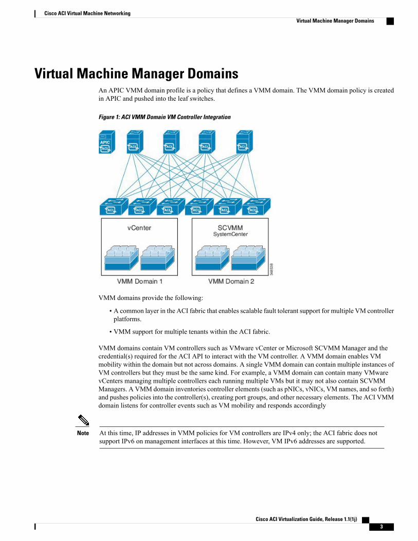
Virtual Machine Manager DomainsAn APIC VMM domain profile is a policy that defines a VMM domain. The VMM domain policy is createdin APIC and pushed into the leaf switches.
Figure 1: ACI VMM Domain VM Controller Integration
VMM domains provide the following:
• A common layer in the ACI fabric that enables scalable fault tolerant support for multiple VM controllerplatforms.
• VMM support for multiple tenants within the ACI fabric.
VMM domains contain VM controllers such as VMware vCenter or Microsoft SCVMMManager and thecredential(s) required for the ACI API to interact with the VM controller. A VMM domain enables VMmobility within the domain but not across domains. A single VMM domain can contain multiple instances ofVM controllers but they must be the same kind. For example, a VMM domain can contain many VMwarevCenters managing multiple controllers each running multiple VMs but it may not also contain SCVMMManagers. A VMM domain inventories controller elements (such as pNICs, vNICs, VM names, and so forth)and pushes policies into the controller(s), creating port groups, and other necessary elements. The ACI VMMdomain listens for controller events such as VM mobility and responds accordingly
At this time, IP addresses in VMM policies for VM controllers are IPv4 only; the ACI fabric does notsupport IPv6 on management interfaces at this time. However, VM IPv6 addresses are supported.
Note
Cisco ACI Virtualization Guide, Release 1.1(1j) 3
Cisco ACI Virtual Machine NetworkingVirtual Machine Manager Domains
VMM Domain VLAN Pool AssociationVLAN pools represent blocks of traffic VLAN identifiers. A VLAN pool is a shared resource and can beconsumed by multiple domains such as VMM domains and Layer 4 to Layer 7 services.
Each pool has an allocation type (static or dynamic), defined at the time of its creation. The allocation typedetermines whether the identifiers contained in it will be used for automatic assignment by the APIC (dynamic)or set explicitly by the administrator (static). By default, all blocks contained within a VLAN pool have thesame allocation type as the pool but users can change the allocation type for encapsulation blocks containedin dynamic pools to static. Doing so excludes them from dynamic allocation.
A VMM domain can associate with only one dynamic VLAN pool. By default, the assignment of VLANidentifiers to EPGs that are associated with VMM domains is done dynamically by the APIC. While dynamicallocation is the default and preferred configuration, an administrator can statically assign a VLAN identifierto an EPG instead. In that case, the identifiers used must be selected from encapsulation blocks in the VLANpool associated with the VMM domain, and their allocation type must be changed to static.
The APIC provisions VMM domain VLAN on leaf ports based on EPG events, either statically binding onleaf ports or based on VM events from controllers such as VMware vCenter or Microsoft SCVMM.
Cisco ACI Virtualization Guide, Release 1.1(1j)4
Cisco ACI Virtual Machine NetworkingVMM Domain VLAN Pool Association

VMM Domain EPG AssociationThe ACI fabric associates tenant application profile EPGs to VMM domains, either automatically by anorchestration component such as Microsoft Azure, or by an APIC administrator creating such configurations.An EPG can span multiple VMM domains and a VMM domain can contain multiple EPGs.
Figure 2: VMM Domain EPG Association
In the illustration above, end points (EP) of the same color are part of the same end point group. For example,all the green EPs are in the same EPG even though they are in two different VMM domains.
Cisco ACI Virtualization Guide, Release 1.1(1j) 5
Cisco ACI Virtual Machine NetworkingVMM Domain EPG Association

Each VMM domain can contain four thousand EPGs (one VLAN can have 4k VLAN IDs). The fabric cansupport up to 16 million virtual networks.
Figure 3: VMM Domain EPG VLAN Consumption
Multiple VMM domains can connect to the same leaf switch if they do not have overlapping VLAN poolson the same port. Similarly, the same VLAN pools can be used across different domains if they do notuse the same port of a leaf switch.
Note
EPGs can use multiple VMM domains in the following ways:
• An EPG within a VMM domain is identified by using an encapsulation identifier that is eitherautomatically managed by the APIC, or statically selected by the administrator. An example is a VLAN,a Virtual Network ID (VNID).
• An EPG can be mapped to multiple physical (for baremetal servers) or virtual domains. It can usedifferent VLAN or VNID encapsulations in each domain.
Cisco ACI Virtualization Guide, Release 1.1(1j)6
Cisco ACI Virtual Machine NetworkingVMM Domain EPG Association
By default, the APIC dynamically manages allocating a VLAN for an EPG. VMware DVS administratorshave the option to configure a specific VLAN for an EPG. In that case, the VLAN is chosen from a staticallocation block within the pool associated with the VMM domain.
Note
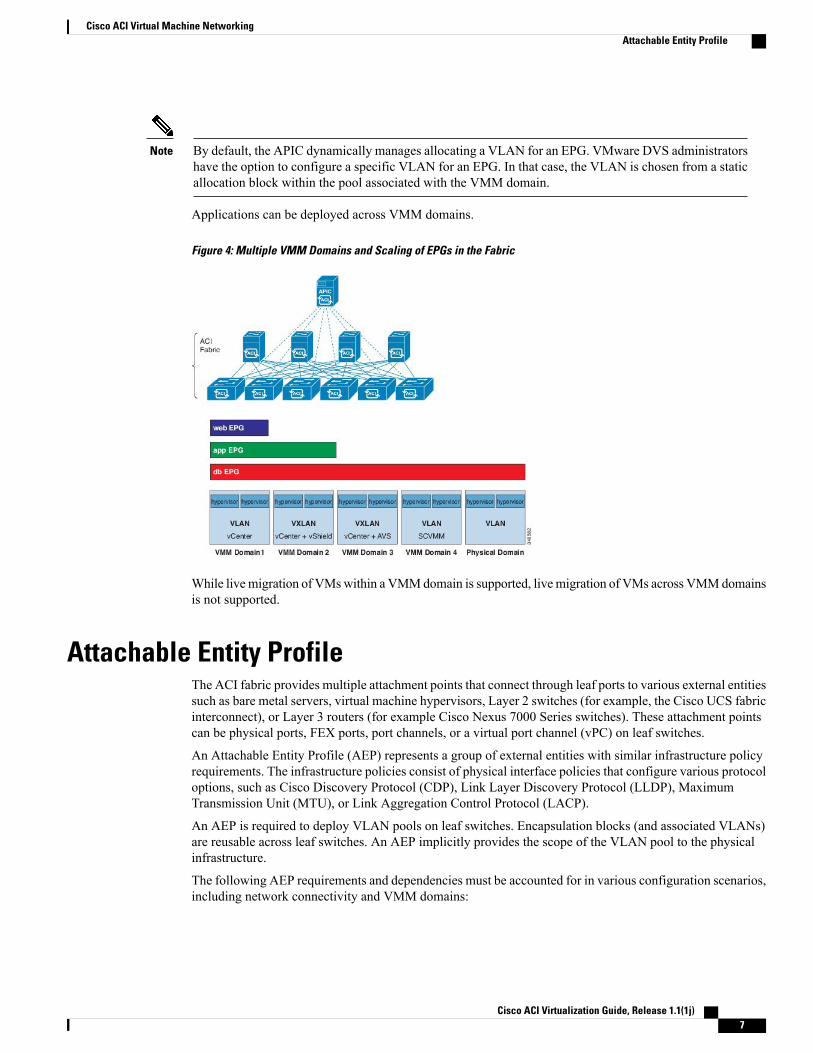
Applications can be deployed across VMM domains.
Figure 4: Multiple VMM Domains and Scaling of EPGs in the Fabric
While livemigration of VMswithin a VMMdomain is supported, livemigration of VMs across VMMdomainsis not supported.
Attachable Entity ProfileThe ACI fabric provides multiple attachment points that connect through leaf ports to various external entitiessuch as bare metal servers, virtual machine hypervisors, Layer 2 switches (for example, the Cisco UCS fabricinterconnect), or Layer 3 routers (for example Cisco Nexus 7000 Series switches). These attachment pointscan be physical ports, FEX ports, port channels, or a virtual port channel (vPC) on leaf switches.
An Attachable Entity Profile (AEP) represents a group of external entities with similar infrastructure policyrequirements. The infrastructure policies consist of physical interface policies that configure various protocoloptions, such as Cisco Discovery Protocol (CDP), Link Layer Discovery Protocol (LLDP), MaximumTransmission Unit (MTU), or Link Aggregation Control Protocol (LACP).
An AEP is required to deploy VLAN pools on leaf switches. Encapsulation blocks (and associated VLANs)are reusable across leaf switches. An AEP implicitly provides the scope of the VLAN pool to the physicalinfrastructure.
The following AEP requirements and dependencies must be accounted for in various configuration scenarios,including network connectivity and VMM domains:
Cisco ACI Virtualization Guide, Release 1.1(1j) 7
Cisco ACI Virtual Machine NetworkingAttachable Entity Profile
• The AEP defines the range of allowed VLANS but it does not provision them. No traffic flows unlessan EPG is deployed on the port. Without defining a VLAN pool in an AEP, a VLAN is not enabled onthe leaf port even if an EPG is provisioned.
• A particular VLAN is provisioned or enabled on the leaf port that is based on EPG events either staticallybinding on a leaf port or based on VM events from external controllers such as VMware vCenter orMicrosoft Azure SCVMM.
A virtual machine manager (VMM) domain automatically derives physical interface policies from the interfacepolicy groups of an AEP.
An override policy at the AEP can be used to specify a different physical interface policy for a VMM domain.This policy is useful in scenarios where a VM controller is connected to the leaf switch through an intermediateLayer 2 node, and a different policy is desired at the leaf switch and VM controller physical ports. For example,you can configure LACP between a leaf switch and a Layer 2 node. At the same time, you can disable LACPbetween the VM controller and the Layer 2 switch by disabling LACP under the AEP override policy.
EPG Policy Resolution and Deployment ImmediacyWhenever an EPG associates to a VMM domain, the administrator can choose the resolution and deploymentpreferences to specify when a policy should be pushed into leaf switches.
Resolution Immediacy
• Pre-provision—Specifies that a policy (for example, VLAN, VXLAN binding, contracts, or filters) isdownloaded to a leaf switch even before a VM controller is attached to the virtual switch (for example,VMware VDS) thereby pre-provisioning the configuration on the switch.
This helps the situation where management traffic for hypervisors/VM controllers are also using thevirtual switch associated to APIC VMM domain (VMM switch).
Deploying a VMM policy such as VLAN on ACI leaf switch requires APIC to collect CDP/LLDPinformation from both hypervisors via VM controller and ACI leaf switch. However if VM Controlleris supposed to use the same VMM policy (VMM switch) to communicate with its hypervisors or evenAPIC, the CDP/LLDP information for hypervisors can never be collected because the policy requiredfor VM controller/hypervisor management traffic is not deployed yet.
When using pre-provision immediacy, policy is downloaded to ACI leaf switch regardless of CDP/LLDPneighborship. Even without a hypervisor host connected to the VMM switch.
• Immediate—Specifies that EPG policies (including contracts and filters) are downloaded to the associatedleaf switch software upon VM controller attachment to a virtual switch. LLDP or OpFlex permissionsare used to resolve the VM controller to leaf node attachments.
The policy will be downloaded to leaf when you add host to the VMM switch. CDP/LLDP neighborshipfrom host to leaf is required.
• On Demand—Specifies that a policy (for example, VLAN, VXLAN bindings, contracts, or filters) ispushed to the leaf node only when a VM controller is attached to a virtual switch and a VM is placed inthe port group (EPG).
The policy will be downloaded to leaf when host is added to VMM switch and virtual machine needsto be placed into port group (EPG). CDP/LLDP neighborship from host to leaf is required.
With both immediate and on demand, if host and leaf lose LLDP/CDP neighborship the policies areremoved.
Cisco ACI Virtualization Guide, Release 1.1(1j)8
Cisco ACI Virtual Machine NetworkingEPG Policy Resolution and Deployment Immediacy
Deployment Immediacy
Once the policies are downloaded to the leaf software, deployment immediacy can specify when the policyis pushed into the hardware policy CAM.
• Immediate—Specifies that the policy is programmed in the hardware policy CAM as soon as the policyis downloaded in the leaf software.
• On Demand—Specifies that the policy is programmed in the hardware policy CAM only when the firstpacket is received through the data path. This process helps to optimize the hardware space.
Guidelines for Deleting VMM DomainsFollow the sequence below to assure that the APIC request to delete a VMM domain automatically triggersthe associated VM controller (for example VMware vCenter or Microsoft SCVMM) to complete the processnormally, and that no orphan EPGs are stranded in the ACI fabric.
1 The VM administrator must detach all the VMs from the port groups (in the case of VMware vCenter) orVM networks (in the case of SCVMM) , created by the APIC.
In the case of Cisco AVS, the VM admin also needs to delete vmk interfaces associated with the CiscoAVS.
2 The ACI administrator deletes the VMM domain in the APIC. The APIC triggers deletion of VMwareVDS or Cisco AVS or SCVMM logical switch and associated objects.
The VM administrator should not delete the virtual switch or associated objects (such as port groups orVM networks); allow the APIC to trigger the virtual switch deletion upon completion of step 2 above.EPGs could be orphaned in the APIC if the VM administrator deletes the virtual switch from the VMcontroller before the VMM domain is deleted in the APIC.
Note
If this sequence is not followed, the VM controller does delete the virtual switch associated with the APICVMM domain. In this scenario, the VM administrator must manually remove the VM and vtep associationsfrom the VM controller, then delete the virtual switch(es) previously associated with the APIC VMMdomain.
Cisco ACI Virtualization Guide, Release 1.1(1j) 9
Cisco ACI Virtual Machine NetworkingGuidelines for Deleting VMM Domains

Cisco ACI Virtualization Guide, Release 1.1(1j)10
Cisco ACI Virtual Machine NetworkingGuidelines for Deleting VMM Domains
C H A P T E R 2Cisco ACI with VMware VDS and VMwarevShield Integration
This chapter contains the following sections:
• Configuring Virtual Machine Networking Policies, page 11
• Creating a VMM Domain Profile, page 14
• Creating VDS Uplink Port Groups, page 22
• Working with Blade Servers, page 22
• Troubleshooting the Cisco ACI and VMware VMM System Integration, page 25
• Additional Reference Sections, page 25
Configuring Virtual Machine Networking PoliciesThe APIC integrates with third-party VM manager (VMM) (for example, VMware vCenter) to extend thebenefits of ACI to the virtualized infrastructure. The APIC enables the ACI policies inside the VMM systemto be used by its administrator.
The following modes of Cisco ACI and VMware VMM integration are supported:
• Vmware VDS—When integrated with Cisco ACI, the VMware vSphere Distributed Switch (VDS)enables you to configure VM networking in the ACI fabric.
• Cisco Application Virtual Switch (AVS)—For information about how to install and configure the CiscoAVS with the Cisco ACI, see details in Cisco ACI and Cisco AVS, on page 41.
APIC Supported VMware VDS VersionsRelease 5.5Release 5.1VMware VDS
SupportedSupportedVMware vCenter
Cisco ACI Virtualization Guide, Release 1.1(1j) 11

Release 5.5Release 5.1VMware VDS
SupportedSupportedVmware vShield
When adding additional VMware ESXi hosts to the VMM domain with VMware vSphere DistributedSwitch (VDS), ensure that the version of ESXi host is compatible with the Distributed Virtual Switch(DVS) version already deployed in the vCenter. For more information about VMware VDS compatibilityrequirements for ESXi hosts, see the VMware documentation.
If the ESXi host version is not compatible with the existing DVS version, vCenter will not be able to addthe ESXi host to the DVS, and an incompatibility error will occur. Modification of the existing DVSVersion setting from the Cisco APIC is not possible. To lower the DVS Version in the vCenter, you needto remove and reapply the VMM domain configuration with a lower setting.
Note
Mapping ACI and VMware ConstructsTable 1: Mapping of ACI and VMware Constructs
VMware TermsCisco APIC Terms
vCenter (Datacenter) or vShieldVM controller
vSphere Distributed Switch (VDS)Virtual Machine Manager (VMM) Domain
Port groupEndpoint group (EPG)
VMware VDS Parameters Managed By APIC
VDS Parameters Managed by APIC
Configurable using APIC PolicyDefault ValueVMware VDS
Yes (Derived from Domain)VMM domain nameName
No"APIC Virtual Switch"Description
Yes (Derived from Domain)VMM domain nameFolder Name
YesHighest supported by vCenterVersion
YesLLDPDiscovery Protocol
Cisco ACI Virtualization Guide, Release 1.1(1j)12
Cisco ACI with VMware VDS and VMware vShield IntegrationMapping ACI and VMware Constructs

Configurable using APIC PolicyDefault ValueVMware VDS
No8Uplink Ports and Uplink Names
NouplinkUplink Name Prefix
Yes9000Maximum MTU
YesdisabledLACP policy
Yes0 sessionsPort mirroring
No2 alarms added at the folder levelAlarms
VDS Port Group Parameters Managed by APIC
Configurable using APIC PolicyDefault ValueVMware VDS Port Group
Yes (Derived from EPG)Tenant Name | Application ProfileName | EPG Name
Name
NoStatic bindingPort binding
YesPicked from VLAN poolVLAN
YesDerived based on port-channelpolicy on APIC
Load balancing algorithm
NoDisabledPromiscuous mode
NoDisabledForged transmit
NoDisabledMac change
NoFalseBlock all ports
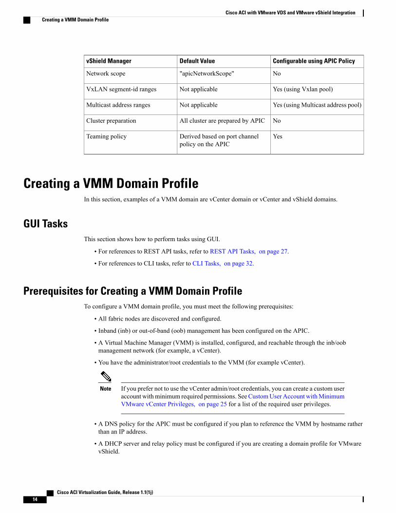
vShield Manager Parameters Managed by APIC
Configurable using APIC PolicyDefault ValuevShield Manager
Yes (Derived from EPG)Tenant Name | Application ProfileName | EPG Name
virtualwire - Name
Nodescvirtualwire - Description
Nopicked fromVxlan pool by vShieldvirtualwire - segment id
Cisco ACI Virtualization Guide, Release 1.1(1j) 13
Cisco ACI with VMware VDS and VMware vShield IntegrationVMware VDS Parameters Managed By APIC
Configurable using APIC PolicyDefault ValuevShield Manager
No"apicNetworkScope"Network scope
Yes (using Vxlan pool)Not applicableVxLAN segment-id ranges
Yes (using Multicast address pool)Not applicableMulticast address ranges
NoAll cluster are prepared by APICCluster preparation
YesDerived based on port channelpolicy on the APIC
Teaming policy
Creating a VMM Domain ProfileIn this section, examples of a VMM domain are vCenter domain or vCenter and vShield domains.
GUI TasksThis section shows how to perform tasks using GUI.
• For references to REST API tasks, refer to REST API Tasks, on page 27.
• For references to CLI tasks, refer to CLI Tasks, on page 32.
Prerequisites for Creating a VMM Domain ProfileTo configure a VMM domain profile, you must meet the following prerequisites:
• All fabric nodes are discovered and configured.
• Inband (inb) or out-of-band (oob) management has been configured on the APIC.
• A Virtual Machine Manager (VMM) is installed, configured, and reachable through the inb/oobmanagement network (for example, a vCenter).
• You have the administrator/root credentials to the VMM (for example vCenter).
If you prefer not to use the vCenter admin/root credentials, you can create a custom useraccount withminimum required permissions. See CustomUser Account withMinimumVMware vCenter Privileges, on page 25 for a list of the required user privileges.
Note
• A DNS policy for the APIC must be configured if you plan to reference the VMM by hostname ratherthan an IP address.
• A DHCP server and relay policy must be configured if you are creating a domain profile for VMwarevShield.
Cisco ACI Virtualization Guide, Release 1.1(1j)14
Cisco ACI with VMware VDS and VMware vShield IntegrationCreating a VMM Domain Profile
vCenter Domain Operational Workflow
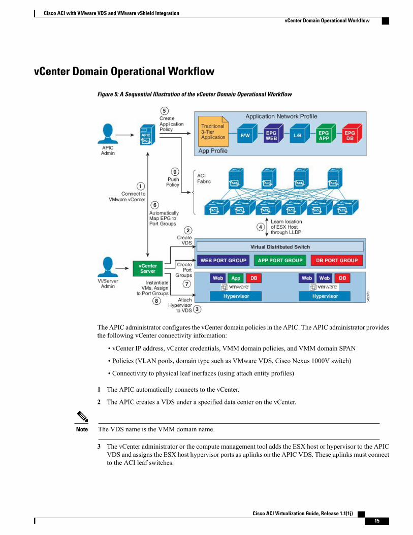
Figure 5: A Sequential Illustration of the vCenter Domain Operational Workflow
The APIC administrator configures the vCenter domain policies in the APIC. The APIC administrator providesthe following vCenter connectivity information:
• vCenter IP address, vCenter credentials, VMM domain policies, and VMM domain SPAN
• Policies (VLAN pools, domain type such as VMware VDS, Cisco Nexus 1000V switch)
• Connectivity to physical leaf inerfaces (using attach entity profiles)
1 The APIC automatically connects to the vCenter.
2 The APIC creates a VDS under a specified data center on the vCenter.
The VDS name is the VMM domain name.Note
3 The vCenter administrator or the compute management tool adds the ESX host or hypervisor to the APICVDS and assigns the ESX host hypervisor ports as uplinks on the APIC VDS. These uplinks must connectto the ACI leaf switches.
Cisco ACI Virtualization Guide, Release 1.1(1j) 15
Cisco ACI with VMware VDS and VMware vShield IntegrationvCenter Domain Operational Workflow
4 TheAPIC learns the location of the hypervisor host to the leaf connectivity using LLDP or CDP informationof the hypervisors.
5 The APIC administrator creates and associates application EPG policies.
6 The APIC administrator associates EPG policies to VMM domains.
7 TheAPIC automatically creates port groups in the VMware vCenter under the VDS. This process provisionsthe network policy in the VMware vCenter.
Note • The port group name is a concatenation of the tenant name, the application profile name, and theEPG name.
• The port group is created under the VDS, and it was created earlier by the APIC.
8 The vCenter administrator or the compute management tool instantiates and assigns VMs to the portgroups.
9 The APIC learns about the VM placements based on the vCenter events. The APIC automatically pushesthe application EPG and its associated policy (for example, contracts and filters) to the ACI fabric.
Creating a vCenter Domain Profile Using the GUIAn overview of the tasks performed in the creation of a vCenter Domain are as follows (details are in thesteps that follow):
• Create/select a switch profile
• Create/select an interface profile
• Create/select an interface policy group
• Create/select VLAN pool
• Create vCenter domain
• Create vCenter credentials
Cisco ACI Virtualization Guide, Release 1.1(1j)16
Cisco ACI with VMware VDS and VMware vShield IntegrationvCenter Domain Operational Workflow
Procedure
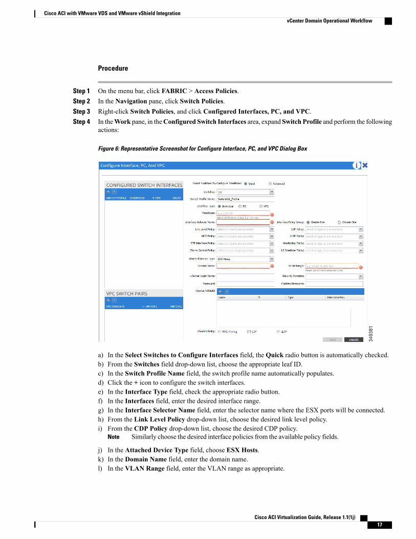
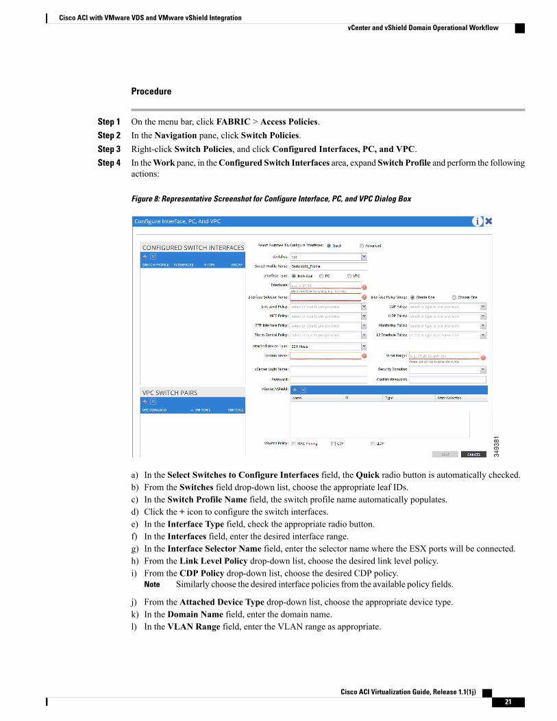
Step 1 On the menu bar, click FABRIC > Access Policies.Step 2 In the Navigation pane, click Switch Policies.Step 3 Right-click Switch Policies, and click Configured Interfaces, PC, and VPC.Step 4 In theWork pane, in theConfigured Switch Interfaces area, expand Switch Profile and perform the following
actions:
Figure 6: Representative Screenshot for Configure Interface, PC, and VPC Dialog Box
a) In the Select Switches to Configure Interfaces field, the Quick radio button is automatically checked.b) From the Switches field drop-down list, choose the appropriate leaf ID.c) In the Switch Profile Name field, the switch profile name automatically populates.d) Click the + icon to configure the switch interfaces.e) In the Interface Type field, check the appropriate radio button.f) In the Interfaces field, enter the desired interface range.g) In the Interface Selector Name field, enter the selector name where the ESX ports will be connected.h) From the Link Level Policy drop-down list, choose the desired link level policy.i) From the CDP Policy drop-down list, choose the desired CDP policy.
Similarly choose the desired interface policies from the available policy fields.Note
j) In the Attached Device Type field, choose ESX Hosts.k) In the Domain Name field, enter the domain name.l) In the VLAN Range field, enter the VLAN range as appropriate.
Cisco ACI Virtualization Guide, Release 1.1(1j) 17
Cisco ACI with VMware VDS and VMware vShield IntegrationvCenter Domain Operational Workflow
We recommend a range of at least 200 VLAN numbers. Do not define a range that includes thereserved VLAN ID for infrastructure network, because that VLAN is for internal use.
Note
m) In the vCenter Login Name field, enter the login name.n) (Optional) From the Security Domains drop-down list, choose the appropriate security domain.o) In the Password field, enter a password.p) In the Confirm Password field, reenter the password.q) Expand vCenter/vShield.
Step 5 In the Create vCenter/vShield Controller dialog box, enter the appropriate information, and click Save.Step 6 In the Configure Interface, PC, And VPC dialog box, in the vSwitch Policy field, check the desired check
box to enable CDP or LLDP. Click Save, and click Submit.Step 7 Verify the new domain and profiles, by performing the following actions:
a) On the menu bar, choose VM Networking > Inventory.b) In the Navigation pane, expand VMware > Domain_name > vCenter_name.In theWork pane, under Properties, view the VMM domain name to verify that the controller is online. IntheWork pane, the vCenter properties are displayed including the operational status. The displayed informationconfirms that connection from the APIC controller to the vCenter server is established, and the inventory isavailable.
vCenter and vShield Domain Operational WorkflowThis workflow shows how the APIC integrates with the vShield Manager to use the hypervisor VXLANfunctionality provided by VMware.
The APIC controls and automates the entire VXLAN preparation and deployment on the vShieldManagerso that users are not required to perform any actions on the vShield Manager.
Note
Prerequisites
• The fabric infrastructure VLAN must be extended to the hypervisor ports. The fabric infrastructureVLAN is used as the outer VLAN in the Ethernet header of the VXLAN data packet. The APICautomatically pushes the fabric infrastructure VLAN to the vShield Manager when preparing the APICVDS for the VXLAN. This is accomplished by checkingEnable Infrastructure VLAN in the attachableentity profile used by this domain profile, as well as by manually enabling and allowing the infrastructureVLAN ID on any intermediate Layer 2 switches between the fabric and hypervisors.
Cisco ACI Virtualization Guide, Release 1.1(1j)18
Cisco ACI with VMware VDS and VMware vShield IntegrationvCenter and vShield Domain Operational Workflow
Operational Workflow
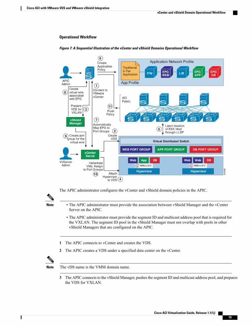
Figure 7: A Sequential Illustration of the vCenter and vShield Domains Operational Workflow
The APIC administrator configures the vCenter and vShield domain policies in the APIC.
Note • The APIC administrator must provide the association between vShield Manager and the vCenterServer on the APIC.
• The APIC administrator must provide the segment ID and multicast address pool that is required forthe VXLAN. The segment ID pool in the vShield Manager must not overlap with pools in othervShield Managers that are configured on the APIC.
1 The APIC connects to vCenter and creates the VDS.
2 The APIC creates a VDS under a specified data center on the vCenter.
The vDS name is the VMM domain name.Note
3 TheAPIC connects to the vShieldManager, pushes the segment ID andmulticast address pool, and preparesthe VDS for VXLAN.
Cisco ACI Virtualization Guide, Release 1.1(1j) 19
Cisco ACI with VMware VDS and VMware vShield IntegrationvCenter and vShield Domain Operational Workflow
4 The vCenter administrator or the compute management tool attaches the hypervisors to the VDS. Allhypervisors in the cluster must be attached to the VDS. Only after that will vShield start VDS preparation.
5 TheAPIC learns the location of the hypervisor host to the leaf connectivity using LLDP or CDP informationfrom the hypervisors.
6 The APIC administrator creates application profiles and EPGs.
7 The APIC administrator associates them to VMM domains.
8 The APIC automatically creates virtual wires in the vShield Manager under the VDS. The APIC reads thesegment ID and the multicast address from the VXLAN virtual wire sent from the vShield Manager.
9 The vShield Manager creates virtual wire port groups in the vCenter server under the VDS.
The virtual wire name is a concatenation of the tenant name, the application profile name, and the EPGname.
Note
10 The vCenter administrator or compute management tool instantiates and assigns VMs to the virtual wireport groups.
11 The APIC automatically pushes the policy to the ACI fabric.
Creating a vCenter and vShield Domain Profile Using the GUIAn overview of the tasks performed in the creation of a vCenter and vShield domains are as follows (detailsare in the steps that follow):
• Create/select a switch profile
• Create/select an interface profile
• Create/select an interface policy group
• Create/select VLAN pool
• Create vCenter and vShield domains
• Create vCenter and vShield credentials
Cisco ACI Virtualization Guide, Release 1.1(1j)20
Cisco ACI with VMware VDS and VMware vShield IntegrationvCenter and vShield Domain Operational Workflow
Procedure
Step 1 On the menu bar, click FABRIC > Access Policies.Step 2 In the Navigation pane, click Switch Policies.Step 3 Right-click Switch Policies, and click Configured Interfaces, PC, and VPC.Step 4 In theWork pane, in theConfigured Switch Interfaces area, expand Switch Profile and perform the following
actions:
Figure 8: Representative Screenshot for Configure Interface, PC, and VPC Dialog Box
a) In the Select Switches to Configure Interfaces field, the Quick radio button is automatically checked.b) From the Switches field drop-down list, choose the appropriate leaf IDs.c) In the Switch Profile Name field, the switch profile name automatically populates.d) Click the + icon to configure the switch interfaces.e) In the Interface Type field, check the appropriate radio button.f) In the Interfaces field, enter the desired interface range.g) In the Interface Selector Name field, enter the selector name where the ESX ports will be connected.h) From the Link Level Policy drop-down list, choose the desired link level policy.i) From the CDP Policy drop-down list, choose the desired CDP policy.
Similarly choose the desired interface policies from the available policy fields.Note
j) From the Attached Device Type drop-down list, choose the appropriate device type.k) In the Domain Name field, enter the domain name.l) In the VLAN Range field, enter the VLAN range as appropriate.
Cisco ACI Virtualization Guide, Release 1.1(1j) 21
Cisco ACI with VMware VDS and VMware vShield IntegrationvCenter and vShield Domain Operational Workflow
We recommend a range of at least 200 VLAN numbers. Do not define a range that includes thereserved VLAN ID for infrastructure network, because that VLAN is for internal use.
Note
m) In the vCenter Login Name field, enter the login name.n) In the Password field, enter a password.o) In the Confirm Password field, reenter the password.p) Expand vCenter/vShield.
Step 5 In the Create vCenter/vShield Controller dialog box, enter the appropriate information.Step 6 In the vSwitch Policy field, check the check boxes for the desired vSwitch policies. Click Save.Step 7 In the Configure Interface, PC, and vPC dialog box, in the vSwitch Policy field, check the desired check
box to enable CDP or LLDP. Click Save, and click Submit.Step 8 Verify the new domain and profiles, by performing the following actions:
a) On the menu bar, choose VM Networking > Inventory.b) In the Navigation pane, expand , and click VMware > Domain_name > vCenter_name.In theWork pane, under Properties, view the VMM domain name to verify that the controller is online. IntheWork pane, the vCenter properties are displayed including the operational status. The displayed informationconfirms that connection from the APIC controller to the vCenter server is established, and the inventory isavailable.
Creating VDS Uplink Port GroupsEach VMM domain appears in the vCenter as a vSphere Distributed Switch (VDS). The virtualizationadministrator associates hosts to the VDS created by the APIC and selects which vmnics to use for the specificVDS. The configuration of the VDS uplinks are performed from the APIC controller by changing the vSwitchconfiguration from the Attach Entity Profile (AEP) that is associated with the VMM domain. You can findthe AEP in the APIC GUI in the Fabric Access Policies configuration area.
When working with ACI and vSphere VMM integration, Link Aggregation Groups (LAGs) are not asupported method of creating interface teams on distributed switches created by the APIC. The APICpushes the necessary interface teaming configuration based on the settings in the Interface Policy Groupand/or AEP vSwitch policy. It is not supported or required to manually create interface teams in vCenter.
Note
Working with Blade Servers
Guidelines for Cisco UCS B-Series ServersWhen integrating blade server systems into Cisco ACI for purposes of VMM integration (for example,integrating Cisco UCS blade servers or other non-Cisco blade servers) you must consider the followingguidelines:
Cisco ACI Virtualization Guide, Release 1.1(1j)22
Cisco ACI with VMware VDS and VMware vShield IntegrationCreating VDS Uplink Port Groups
This example shows how to configure a port channel access policy for integrating Cisco UCS blade servers.You can use similar steps to set up a virtual port channel or individual link access policies depending uponhow your Cisco UCS blade server uplinks are connected to the fabric. If no port channel is explicitlyconfigured on the APIC for the UCS blade server uplinks, the default behavior will be mac-pinning.
Note
• The VM endpoint learning relies on either the CDP or LLDP protocol. If supported, CDPmust be enabledall the way from the leaf switch port through any blade switches and to the blade adapters.
• The APIC does not manage fabric interconnects and the blade server, so any UCS specific policies suchas CDP or port channel policies must be configured from the UCS Manager.
• VLANs defined in the VLAN pool used by the attachable access entity profile on the APIC, must alsobe manually created on the UCS and allowed on the appropriate uplinks connecting to the fabric. Thismust include the infrastructure VLAN if applicable. For details, see the Cisco UCS Manager GUIConfiguration Guide.
•When you are working with the Cisco UCS B-series server and using an APIC policy, Link LayerDiscovery Protocol (LLDP) is not supported.
• Cisco Discovery Prototol (CDP) is disabled by default in Cisco UCS Manager. In Cisco UCS Manager,you must enable CDP by creating a Network Control Policy.
• Do not enable fabric failover on the adapters in the UCS server service profiles. Cisco recommends thatyou allow the hypervisor to handle failover at the virtual switch layer so that load balancing of trafficis appropriately performed.
Symptom: The change of management IP of the unmanaged node such as blade switch or fabric interconnectgets updated in the VMware vCenter, but the VMware vCenter does not send any events to APIC.
Condition: This causes the APIC to be out of sync with VMware vCenter.
Workaround: You need to trigger an inventory pull for the VMware vCenter controller that manages ESXservers behind the unmanaged node.
Note
Setting up an Access Policy for a Blade Server Using the GUI
Before You Begin
To operate with the Cisco APIC, the Cisco UCS Fabric Interconnect must be at least a version 2.2(1c). Allcomponents, such as the BIOS, CIMC, and the adapter must be a version 2.2(1c) or later. For further details,see the Cisco UCS Manager CLI Configuration Guide.
Cisco ACI Virtualization Guide, Release 1.1(1j) 23
Cisco ACI with VMware VDS and VMware vShield IntegrationSetting up an Access Policy for a Blade Server Using the GUI
Procedure
Step 1 On the menu bar, choose FABRIC > Access Policies.Step 2 In theWork pane, click Configure Interface, PC, and vPC.Step 3 In the Configure Interface, PC, and vPC dialog box, click the + icon to select switches.Step 4 In the Switches field, from the drop-down list, choose the desired switch IDs.Step 5 Click the + icon to configure the switch interfaces.Step 6 In the Interface Type field, click the VPC radio button.Step 7 In the Interfaces field, enter the appropriate interface or interface range that is connected to the blade server.Step 8 In the Interface Selector Name field, enter a name.Step 9 From the CDP Policy drop-down list, choose default
The default CDP policy is set to disabled. (Between the leaf switch and the blade server, CDPmust be disabled.)
Step 10 From the LLDP Policy drop-down list, choose default.The default LLDP policy is set to enabled for the receive and transmit states. (Between the leaf switch andthe blade server, LLDP must be enabled.)
Step 11 From the LACP Policy drop-down list, choose Create LACP Policy.Between the leaf switch and the blade server, the LACP policy must be set to active.
Step 12 In the Create LACP Policy dialog box, perform the following actions:a) In the Name field, enter a name for the policy.b) In theMode field, the Active radio button is checked.c) Keep the remaining default values and click Submit.
Step 13 From the Attached Device Type field drop-down list, choose ESX Hosts.Step 14 In the Domain Name field, enter a name as appropriate.Step 15 In the VLAN Range field, enter the range.Step 16 In the vCenter Login Name field, enter the login name.Step 17 In the Password field, and the Confirm Password field, enter the password.Step 18 Expand the vCenter/vShield field, and in the Create vCenter/vShield Controller dialog box, enter the
desired content and click OK.Step 19 In the vSwitch Policy field, perform the following actions:
Between the blade server and the ESX hypervisor, CDP must be enabled, LLDP must be disabled, and LACPmust be disabled so Mac Pinning must be set.
a) Check theMAC Pinning check box.b) Check the CDP check box.c) Leave the LLDP check box unchecked because LLDP must remain disabled.
Step 20 Click Save, and click Save again. Click Submit.The access policy is set.
Cisco ACI Virtualization Guide, Release 1.1(1j)24
Cisco ACI with VMware VDS and VMware vShield IntegrationSetting up an Access Policy for a Blade Server Using the GUI
Troubleshooting the Cisco ACI and VMware VMM SystemIntegration
For troubleshooting information, see the following links:
• Cisco APIC Troubleshooting Guide
• ACI Troubleshooting Book
Additional Reference Sections
Custom User Account with Minimum VMware vCenter PrivilegesTo configure the vCenter from Cisco APIC, your credentials must allow the following minimum set ofprivileges within the vCenter:
• Alarms
• Distributed Switch
• dvPort Group
• Folder
• Host
◦Host.Configuration.Advanced settings
◦Host.Local operations.Reconfigure virtual machine
◦Host.Configuration.Network configuration
• Network
• Virtual machine
◦Virtual machine.Configuration.Modify device settings
◦Virtual machine.Configuration.Settings
This allows the APIC to send vmware API commands to vCenter to allow the creation of the DVS/AVS,creation of the VMK interface (AVS), publish port groups and relay all necessary alerts.
Quarantine Port GroupsThe quarantine port group feature provides a method to clear port group assignments under certaincircumstances. In the VMware vCenter, when a VMware vSphere Distributed Switch (VDS) is created, aquarantine port group is created in the VDS by default. The quarantine port group default policy is to blockall ports.
Cisco ACI Virtualization Guide, Release 1.1(1j) 25
Cisco ACI with VMware VDS and VMware vShield IntegrationTroubleshooting the Cisco ACI and VMware VMM System Integration
As part of integration with Layer 4 to Layer 7 virtual service appliances, such as a load balancer or firewall,the Application Policy Infrastructure Controller (APIC) creates service port groups in vCenter for servicestitching and orchestrates placement of virtual appliances, such as service virtual machines (VMs), in theseservice port groups as part of the service graph rendering mechanism. When the service graph is deleted, theservice VMs are automatically moved to the quarantine port group. This auto-move to a quarantine port groupon delete is only done for service VMs, which are orchestrated by the APIC.
You can take further action with the port in quarantine port group as desired. For example, you can migrateall of the ports from the quarantine port group to another port group, such as a VM network.
The quarantine port group mechanism is not applicable to regular tenant endpoint groups (EPGs) and theirassociated port groups and tenant VMs. Therefore, if the tenant EPG is deleted, any tenant VMs present inthe associated port group remains intact and they will not be moved to the quarantine port group. The placementof tenant VMs into the tenant port group is outside the realm of the APIC.
On-Demand VMM Inventory RefreshTriggered Inventory provides a manual trigger option to pull and resynchronize inventory between a virtualmachine manager (VMM) controller and the APIC. Triggered inventory provides instant recovery fromout-of-sync scenarios. Triggered inventory is applicable to vCenter VMM controllers only. It is not requiredin normal scenarios and should be used with discretion since inventory sync is a burdensome operation forthe VMM controllers.
The APIC initiates vCenter inventory pull. Hosts, VMs, DVS, uplink port groups, NICs, and so on are retrievedas part of the initial VMM Controller creation. Further changes in vCenter are learned through the eventsubscription mechanism. This enables the APIC VMM manager to send endpoint attach/detach updates tothe APIC policy manager which downloads updated policies to leaf switches accordingly.
When there is a process restart, leadership change, or background periodic 24 hour inventory audit, the APICdoes inventory pull to keep VMM inventory synchronized between VMM controllers and the APIC. Whenheavily loaded, the vCenter fails to provide the APIC an appropriate inventory event notification. In this case,triggered inventory helps to keep the APIC in synchronization with the vCenter.
Guidelines for Migrating a vCenter Hypervisor VMK0 to an ACI Inband VLANFollow the guidelines below to migrate the default vCenter hypervisor VMK0 out of bound connectivity toACI inband ports. AnACI fabric infrastructure administrator configures the APICwith the necessary policies,then the vCenter administrator migrates the VMK0 to the appropriate ACI port group.
Create the Necessary Management EPG Policies in APICAs an ACI fabric infrastructure administrator, use the following guidelines when creating the managementtenant and VMM domain policies:
• Choose a VLAN to use for ESX management.
• Add the VLAN chosen for ESX management to a range (or Encap Block) in the VLAN pool associatedwith the target VMM domain. The range where this VLAN is added must have allocation mode set tostatic allocation.
• Create a management EPG in the ACI management tenant (mgmt).
Cisco ACI Virtualization Guide, Release 1.1(1j)26
Cisco ACI with VMware VDS and VMware vShield IntegrationOn-Demand VMM Inventory Refresh
• Verify that the bridge domain associated with the management EPG is also associated with the privatenetwork (inb).
• Associate the management EPG with the target VMM domain as follows:
◦Use resolution immediacy as pre-provision.
◦Specify the management VLAN in the Port Encap field of the VM domain profile association.
As a result, APIC creates the port group under vCenter with VLAN specified by the user. APIC alsoautomatically pushes the policies on the leaf switches associated with the VMM domain and AttachEntity Profile (AEP).
Migrate the VMK0 to the Inband ACI VLANBy default vCenter configures the default VMK0 on the hypervisor management interface. The ACI policescreated above enable the vCenter administrator to migrate the default VMK0 to the port group that is createdby APIC. Doing so frees up the hypervisor management port.
REST API TasksThis section shows how to perform tasks using REST API.
• For references to GUI tasks, refer to sections, Creating a VMMDomain Profile, on page 14 and Settingup an Access Policy for a Blade Server Using the GUI, on page 23.
• For references to CLI tasks, refer to CLI Tasks, on page 32.
Creating a vCenter Domain Profile Using the REST API
Procedure
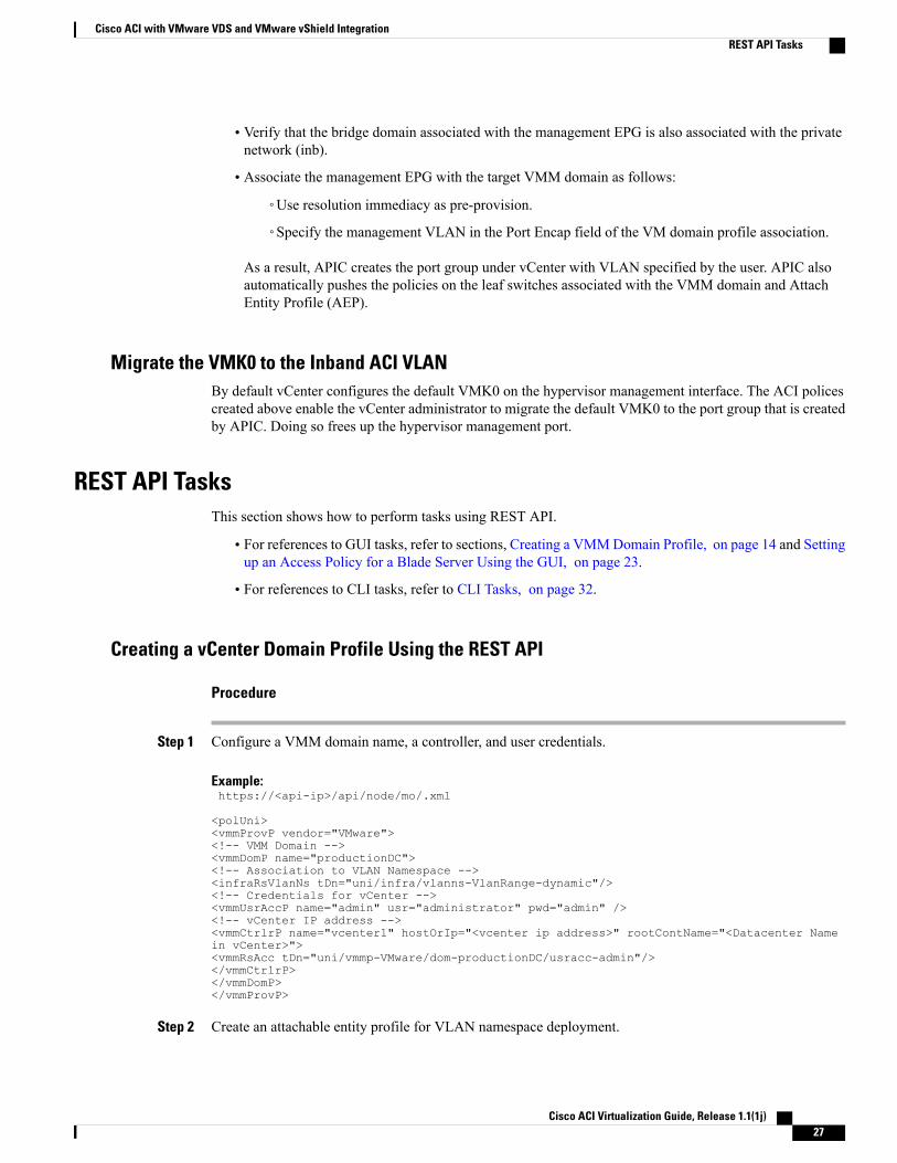
Step 1 Configure a VMM domain name, a controller, and user credentials.
Example:https://<api-ip>/api/node/mo/.xml
<polUni><vmmProvP vendor="VMware"><!-- VMM Domain --><vmmDomP name="productionDC"><!-- Association to VLAN Namespace --><infraRsVlanNs tDn="uni/infra/vlanns-VlanRange-dynamic"/><!-- Credentials for vCenter --><vmmUsrAccP name="admin" usr="administrator" pwd="admin" /><!-- vCenter IP address --><vmmCtrlrP name="vcenter1" hostOrIp="<vcenter ip address>" rootContName="<Datacenter Namein vCenter>"><vmmRsAcc tDn="uni/vmmp-VMware/dom-productionDC/usracc-admin"/></vmmCtrlrP></vmmDomP></vmmProvP>
Step 2 Create an attachable entity profile for VLAN namespace deployment.
Cisco ACI Virtualization Guide, Release 1.1(1j) 27
Cisco ACI with VMware VDS and VMware vShield IntegrationREST API Tasks
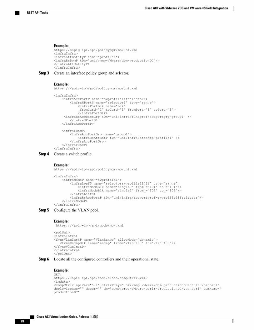
Example:https://<apic-ip>/api/policymgr/mo/uni.xml<infraInfra><infraAttEntityP name="profile1"><infraRsDomP tDn="uni/vmmp-VMware/dom-productionDC"/></infraAttEntityP></infraInfra>
Step 3 Create an interface policy group and selector.
Example:https://<apic-ip>/api/policymgr/mo/uni.xml
<infraInfra><infraAccPortP name="swprofile1ifselector">
<infraHPortS name="selector1" type="range"><infraPortBlk name="blk"fromCard="1" toCard="1" fromPort="1" toPort="3"></infraPortBlk>
<infraRsAccBaseGrp tDn="uni/infra/funcprof/accportgrp-group1" /></infraHPortS>
</infraAccPortP>
<infraFuncP><infraAccPortGrp name="group1">
<infraRsAttEntP tDn="uni/infra/attentp-profile1" /></infraAccPortGrp>
</infraFuncP></infraInfra>
Step 4 Create a switch profile.
Example:https://<apic-ip>/api/policymgr/mo/uni.xml
<infraInfra><infraNodeP name="swprofile1">
<infraLeafS name="selectorswprofile11718" type="range"><infraNodeBlk name="single0" from_="101" to_="101"/><infraNodeBlk name="single1" from_="102" to_="102"/>
</infraLeafS><infraRsAccPortP tDn="uni/infra/accportprof-swprofile1ifselector"/>
</infraNodeP></infraInfra>
Step 5 Configure the VLAN pool.
Example:https://<apic-ip>/api/node/mo/.xml
<polUni><infraInfra><fvnsVlanInstP name="VlanRange" allocMode="dynamic">
<fvnsEncapBlk name="encap" from="vlan-100" to="vlan-400"/></fvnsVlanInstP></infraInfra></polUni>
Step 6 Locate all the configured controllers and their operational state.
Example:GET:https://<apic-ip>/api/node/class/compCtrlr.xml?<imdata><compCtrlr apiVer="5.1" ctrlrPKey="uni/vmmp-VMware/dom-productionDC/ctrlr-vcenter1"deployIssues="" descr="" dn="comp/prov-VMware/ctrlr-productionDC-vcenter1" domName="productionDC"
Cisco ACI Virtualization Guide, Release 1.1(1j)28
Cisco ACI with VMware VDS and VMware vShield IntegrationREST API Tasks
hostOrIp="esx1" mode="default" model="VMware vCenter Server 5.1.0 build-756313"name="vcenter1" operSt="online" port="0" pwd="" remoteOperIssues="" scope="vm"usr="administrator" vendor="VMware, Inc." ... /></imdata>
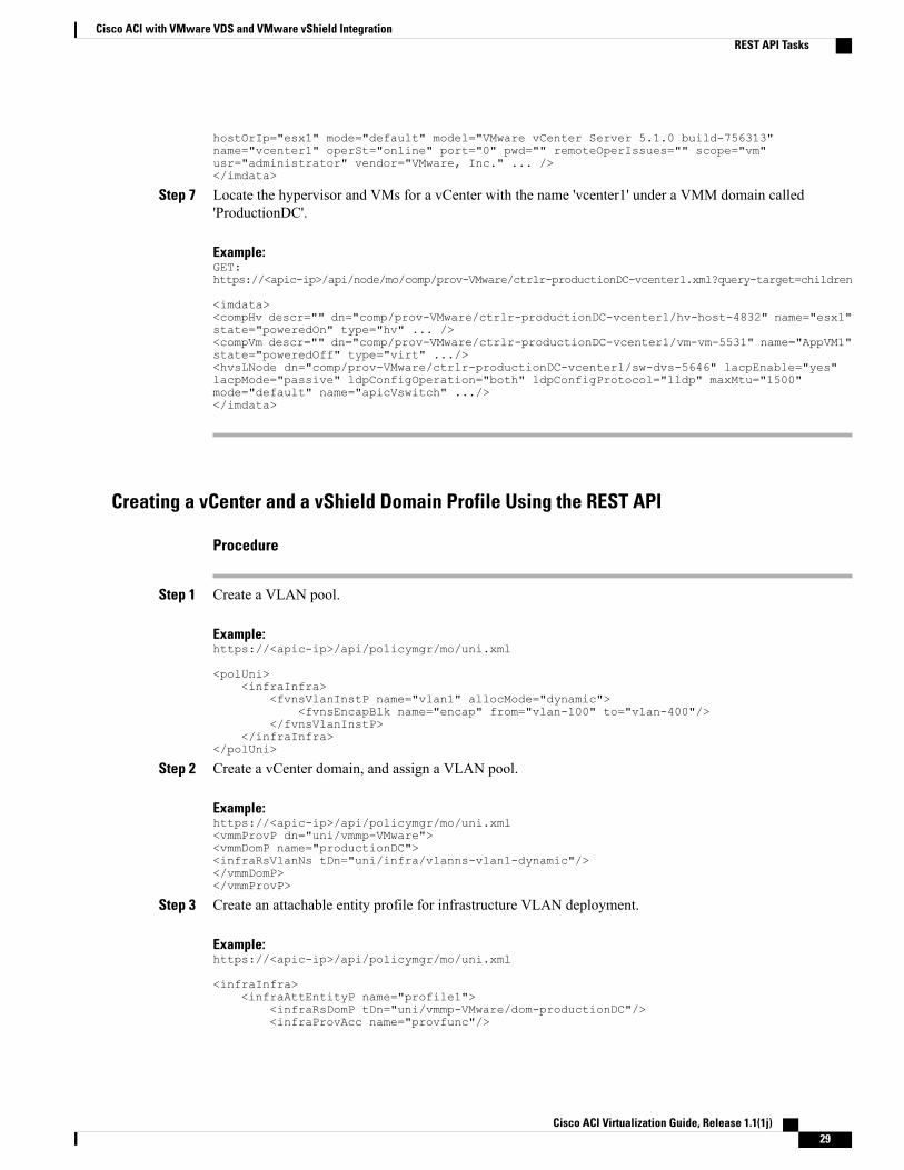
Step 7 Locate the hypervisor and VMs for a vCenter with the name 'vcenter1' under a VMM domain called'ProductionDC'.
Example:GET:https://<apic-ip>/api/node/mo/comp/prov-VMware/ctrlr-productionDC-vcenter1.xml?query-target=children
<imdata><compHv descr="" dn="comp/prov-VMware/ctrlr-productionDC-vcenter1/hv-host-4832" name="esx1"state="poweredOn" type="hv" ... /><compVm descr="" dn="comp/prov-VMware/ctrlr-productionDC-vcenter1/vm-vm-5531" name="AppVM1"state="poweredOff" type="virt" .../><hvsLNode dn="comp/prov-VMware/ctrlr-productionDC-vcenter1/sw-dvs-5646" lacpEnable="yes"lacpMode="passive" ldpConfigOperation="both" ldpConfigProtocol="lldp" maxMtu="1500"mode="default" name="apicVswitch" .../></imdata>
Creating a vCenter and a vShield Domain Profile Using the REST API
Procedure
Step 1 Create a VLAN pool.
Example:https://<apic-ip>/api/policymgr/mo/uni.xml
<polUni><infraInfra>
<fvnsVlanInstP name="vlan1" allocMode="dynamic"><fvnsEncapBlk name="encap" from="vlan-100" to="vlan-400"/>
</fvnsVlanInstP></infraInfra>
</polUni>
Step 2 Create a vCenter domain, and assign a VLAN pool.
Example:https://<apic-ip>/api/policymgr/mo/uni.xml<vmmProvP dn="uni/vmmp-VMware"><vmmDomP name="productionDC"><infraRsVlanNs tDn="uni/infra/vlanns-vlan1-dynamic"/></vmmDomP></vmmProvP>
Step 3 Create an attachable entity profile for infrastructure VLAN deployment.
Example:https://<apic-ip>/api/policymgr/mo/uni.xml
<infraInfra><infraAttEntityP name="profile1">
<infraRsDomP tDn="uni/vmmp-VMware/dom-productionDC"/><infraProvAcc name="provfunc"/>
Cisco ACI Virtualization Guide, Release 1.1(1j) 29
Cisco ACI with VMware VDS and VMware vShield IntegrationREST API Tasks
</infraAttEntityP></infraInfra>
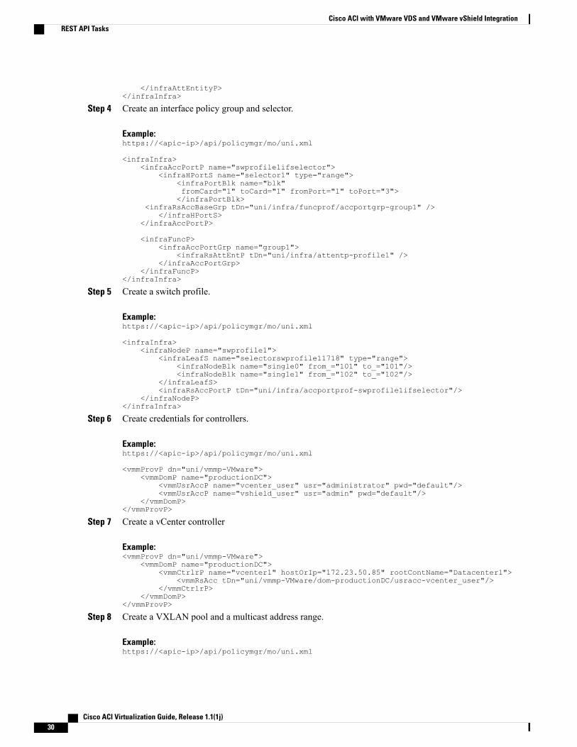
Step 4 Create an interface policy group and selector.
Example:https://<apic-ip>/api/policymgr/mo/uni.xml
<infraInfra><infraAccPortP name="swprofile1ifselector">
<infraHPortS name="selector1" type="range"><infraPortBlk name="blk"fromCard="1" toCard="1" fromPort="1" toPort="3"></infraPortBlk>
<infraRsAccBaseGrp tDn="uni/infra/funcprof/accportgrp-group1" /></infraHPortS>
</infraAccPortP>
<infraFuncP><infraAccPortGrp name="group1">
<infraRsAttEntP tDn="uni/infra/attentp-profile1" /></infraAccPortGrp>
</infraFuncP></infraInfra>
Step 5 Create a switch profile.
Example:https://<apic-ip>/api/policymgr/mo/uni.xml
<infraInfra><infraNodeP name="swprofile1">
<infraLeafS name="selectorswprofile11718" type="range"><infraNodeBlk name="single0" from_="101" to_="101"/><infraNodeBlk name="single1" from_="102" to_="102"/>
</infraLeafS><infraRsAccPortP tDn="uni/infra/accportprof-swprofile1ifselector"/>
</infraNodeP></infraInfra>
Step 6 Create credentials for controllers.
Example:https://<apic-ip>/api/policymgr/mo/uni.xml
<vmmProvP dn="uni/vmmp-VMware"><vmmDomP name="productionDC">
<vmmUsrAccP name="vcenter_user" usr="administrator" pwd="default"/><vmmUsrAccP name="vshield_user" usr="admin" pwd="default"/>
</vmmDomP></vmmProvP>
Step 7 Create a vCenter controller
Example:<vmmProvP dn="uni/vmmp-VMware">
<vmmDomP name="productionDC"><vmmCtrlrP name="vcenter1" hostOrIp="172.23.50.85" rootContName="Datacenter1">
<vmmRsAcc tDn="uni/vmmp-VMware/dom-productionDC/usracc-vcenter_user"/></vmmCtrlrP>
</vmmDomP></vmmProvP>
Step 8 Create a VXLAN pool and a multicast address range.
Example:https://<apic-ip>/api/policymgr/mo/uni.xml
Cisco ACI Virtualization Guide, Release 1.1(1j)30
Cisco ACI with VMware VDS and VMware vShield IntegrationREST API Tasks
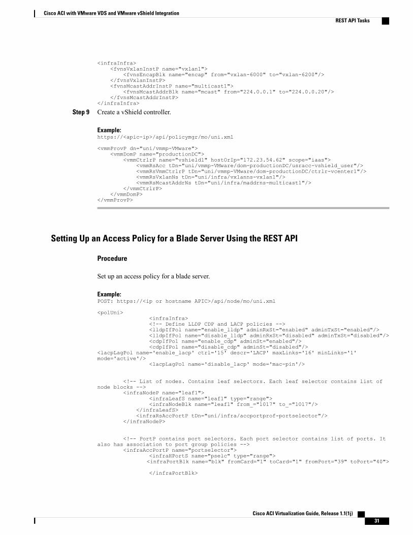
<infraInfra><fvnsVxlanInstP name="vxlan1">
<fvnsEncapBlk name="encap" from="vxlan-6000" to="vxlan-6200"/></fvnsVxlanInstP><fvnsMcastAddrInstP name="multicast1">
<fvnsMcastAddrBlk name="mcast" from="224.0.0.1" to="224.0.0.20"/></fvnsMcastAddrInstP>
</infraInfra>
Step 9 Create a vShield controller.
Example:https://<apic-ip>/api/policymgr/mo/uni.xml
<vmmProvP dn="uni/vmmp-VMware"><vmmDomP name="productionDC">
<vmmCtrlrP name="vshield1" hostOrIp="172.23.54.62" scope="iaas"><vmmRsAcc tDn="uni/vmmp-VMware/dom-productionDC/usracc-vshield_user"/><vmmRsVmmCtrlrP tDn="uni/vmmp-VMware/dom-productionDC/ctrlr-vcenter1"/><vmmRsVxlanNs tDn="uni/infra/vxlanns-vxlan1"/><vmmRsMcastAddrNs tDn="uni/infra/maddrns-multicast1"/>
</vmmCtrlrP></vmmDomP>
</vmmProvP>
Setting Up an Access Policy for a Blade Server Using the REST API
Procedure
Set up an access policy for a blade server.
Example:POST: https://<ip or hostname APIC>/api/node/mo/uni.xml
<polUni><infraInfra><!-- Define LLDP CDP and LACP policies --><lldpIfPol name="enable_lldp" adminRxSt="enabled" adminTxSt="enabled"/><lldpIfPol name="disable_lldp" adminRxSt="disabled" adminTxSt="disabled"/><cdpIfPol name="enable_cdp" adminSt="enabled"/><cdpIfPol name="disable_cdp" adminSt="disabled"/>
<lacpLagPol name='enable_lacp' ctrl='15' descr='LACP' maxLinks='16' minLinks='1'mode='active'/>
<lacpLagPol name='disable_lacp' mode='mac-pin'/>
<!-- List of nodes. Contains leaf selectors. Each leaf selector contains list ofnode blocks -->
<infraNodeP name="leaf1"><infraLeafS name="leaf1" type="range"><infraNodeBlk name="leaf1" from_="1017" to_="1017"/>
</infraLeafS><infraRsAccPortP tDn="uni/infra/accportprof-portselector"/>
</infraNodeP>
<!-- PortP contains port selectors. Each port selector contains list of ports. Italso has association to port group policies -->
<infraAccPortP name="portselector"><infraHPortS name="pselc" type="range"><infraPortBlk name="blk" fromCard="1" toCard="1" fromPort="39" toPort="40">
</infraPortBlk>
Cisco ACI Virtualization Guide, Release 1.1(1j) 31
Cisco ACI with VMware VDS and VMware vShield IntegrationREST API Tasks
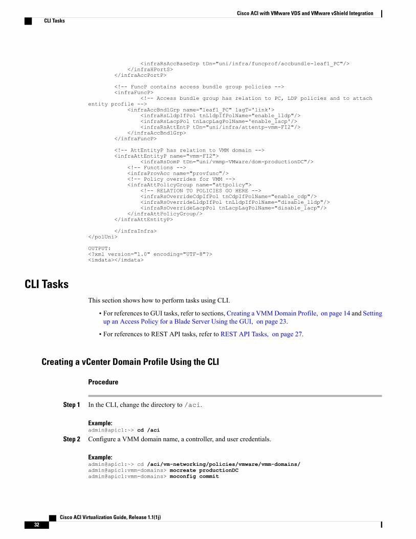
<infraRsAccBaseGrp tDn="uni/infra/funcprof/accbundle-leaf1_PC"/></infraHPortS>
</infraAccPortP>
<!-- FuncP contains access bundle group policies --><infraFuncP>
<!-- Access bundle group has relation to PC, LDP policies and to attachentity profile -->
<infraAccBndlGrp name="leaf1_PC" lagT='link'><infraRsLldpIfPol tnLldpIfPolName="enable_lldp"/><infraRsLacpPol tnLacpLagPolName='enable_lacp'/><infraRsAttEntP tDn="uni/infra/attentp-vmm-FI2"/>
</infraAccBndlGrp></infraFuncP>
<!-- AttEntityP has relation to VMM domain --><infraAttEntityP name="vmm-FI2">
<infraRsDomP tDn="uni/vmmp-VMware/dom-productionDC"/><!-- Functions --><infraProvAcc name="provfunc"/><!-- Policy overrides for VMM --><infraAttPolicyGroup name="attpolicy">
<!-- RELATION TO POLICIES GO HERE --><infraRsOverrideCdpIfPol tnCdpIfPolName="enable_cdp"/><infraRsOverrideLldpIfPol tnLldpIfPolName="disable_lldp"/><infraRsOverrideLacpPol tnLacpLagPolName="disable_lacp"/>
</infraAttPolicyGroup/></infraAttEntityP>
</infraInfra></polUni>
OUTPUT:<?xml version="1.0" encoding="UTF-8"?><imdata></imdata>
CLI TasksThis section shows how to perform tasks using CLI.
• For references to GUI tasks, refer to sections, Creating a VMMDomain Profile, on page 14 and Settingup an Access Policy for a Blade Server Using the GUI, on page 23.
• For references to REST API tasks, refer to REST API Tasks, on page 27.
Creating a vCenter Domain Profile Using the CLI
Procedure
Step 1 In the CLI, change the directory to /aci.
Example:admin@apic1:~> cd /aci
Step 2 Configure a VMM domain name, a controller, and user credentials.
Example:admin@apic1:~> cd /aci/vm-networking/policies/vmware/vmm-domains/admin@apic1:vmm-domains> mocreate productionDCadmin@apic1:vmm-domains> moconfig commit
Cisco ACI Virtualization Guide, Release 1.1(1j)32
Cisco ACI with VMware VDS and VMware vShield IntegrationCLI Tasks
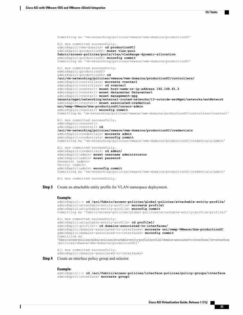
Committing mo 'vm-networking/policies/vmware/vmm-domains/productionDC'
All mos committed successfully.admin@apic1:vmm-domains> cd productionDC/admin@apic1:productionDC> moset vlan-poolfabric/access-policies/pools/vlan/vlanRange-dynamic-allocationadmin@apic1:productionDC> moconfig commitCommitting mo 'vm-networking/policies/vmware/vmm-domains/productionDC'
All mos committed successfully.admin@apic1:productionDC>admin@apic1:productionDC> cd/aci/vm-networking/policies/vmware/vmm-domains/productionDC/controllers/admin@apic1:controllers> mocreate vcenter1admin@apic1:controllers> cd vcenter1admin@apic1:vcenter1> moset host-name-or-ip-address 192.168.81.2admin@apic1:vcenter1> moset datacenter Datacenter1admin@apic1:vcenter1> moset management-epgtenants/mgmt/networking/external-routed-networks/l3-outside-extMgmt/networks/extNetworkadmin@apic1:vcenter1> moset associated-credentialuni/vmmp-VMware/dom-productionDC/usracc-adminadmin@apic1:vcenter1> moconfig commitCommitting mo 'vm-networking/policies/vmware/vmm-domains/productionDC/controllers/vcenter1'
All mos committed successfully.admin@apic1:vcenter1>admin@apic1:vcenter1> cd/aci/vm-networking/policies/vmware/vmm-domains/productionDC/credentialsadmin@apic1:credentials> mocreate adminadmin@apic1:credentials> moconfig commitCommitting mo 'vm-networking/policies/vmware/vmm-domains/productionDC/credentials/admin'
All mos committed successfully.admin@apic1:credentials> cd admin/admin@apic1:admin> moset username administratoradmin@apic1:admin> moset passwordPassword: <admin>Verify: <admin>admin@apic1:admin> moconfig commitCommitting mo 'vm-networking/policies/vmware/vmm-domains/productionDC/credentials/admin'
All mos committed successfully.
Step 3 Create an attachable entity profile for VLAN namespace deployment.
Example:admin@apic1:~> cd /aci/fabric/access-policies/global-policies/attachable-entity-profile/admin@apic1:attachable-entity-profile> mocreate profile1admin@apic1:attachable-entity-profile> moconfig commitCommitting mo 'fabric/access-policies/global-policies/attachable-entity-profile/profile1'
All mos committed successfully.admin@apic1:attachable-entity-profile> cd profile1/admin@apic1:profile1> cd domains-associated-to-interfaces/admin@apic1:domains-associated-to-interfaces> mocreate uni/vmmp-VMware/dom-productionDCadmin@apic1:domains-associated-to-interfaces> moconfig commitCommitting mo'fabric/access-policies/global-policies/attachable-entity-profile/profile1/domains-associated-to-interfaces/[vm-networking/policies/vmware/vmm-domains/productionDC]'
All mos committed successfully.admin@apic1:domains-associated-to-interfaces>
Step 4 Create an interface policy group and selector.
Example:admin@apic1:~> cd /aci/fabric/access-policies/interface-policies/policy-groups/interfaceadmin@apic1:interface> mocreate group1
Cisco ACI Virtualization Guide, Release 1.1(1j) 33
Cisco ACI with VMware VDS and VMware vShield IntegrationCLI Tasks
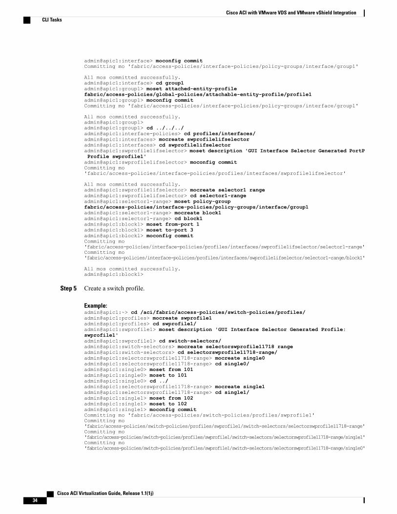
admin@apic1:interface> moconfig commitCommitting mo 'fabric/access-policies/interface-policies/policy-groups/interface/group1'
All mos committed successfully.admin@apic1:interface> cd group1admin@apic1:group1> moset attached-entity-profilefabric/access-policies/global-policies/attachable-entity-profile/profile1admin@apic1:group1> moconfig commitCommitting mo 'fabric/access-policies/interface-policies/policy-groups/interface/group1'
All mos committed successfully.admin@apic1:group1>admin@apic1:group1> cd ../../../admin@apic1:interface-policies> cd profiles/interfaces/admin@apic1:interfaces> mocreate swprofile1ifselectoradmin@apic1:interfaces> cd swprofile1ifselectoradmin@apic1:swprofile1ifselector> moset description 'GUI Interface Selector Generated PortPProfile swprofile1'admin@apic1:swprofile1ifselector> moconfig commitCommitting mo'fabric/access-policies/interface-policies/profiles/interfaces/swprofile1ifselector'
All mos committed successfully.admin@apic1:swprofile1ifselector> mocreate selector1 rangeadmin@apic1:swprofile1ifselector> cd selector1-rangeadmin@apic1:selector1-range> moset policy-groupfabric/access-policies/interface-policies/policy-groups/interface/group1admin@apic1:selector1-range> mocreate block1admin@apic1:selector1-range> cd block1admin@apic1:block1> moset from-port 1admin@apic1:block1> moset to-port 3admin@apic1:block1> moconfig commitCommitting mo'fabric/access-policies/interface-policies/profiles/interfaces/swprofile1ifselector/selector1-range'Committing mo'fabric/access-policies/interface-policies/profiles/interfaces/swprofile1ifselector/selector1-range/block1'
All mos committed successfully.admin@apic1:block1>
Step 5 Create a switch profile.
Example:admin@apic1:~> cd /aci/fabric/access-policies/switch-policies/profiles/admin@apic1:profiles> mocreate swprofile1admin@apic1:profiles> cd swprofile1/admin@apic1:swprofile1> moset description 'GUI Interface Selector Generated Profile:swprofile1'admin@apic1:swprofile1> cd switch-selectors/admin@apic1:switch-selectors> mocreate selectorswprofile11718 rangeadmin@apic1:switch-selectors> cd selectorswprofile11718-range/admin@apic1:selectorswprofile11718-range> mocreate single0admin@apic1:selectorswprofile11718-range> cd single0/admin@apic1:single0> moset from 101admin@apic1:single0> moset to 101admin@apic1:single0> cd ../admin@apic1:selectorswprofile11718-range> mocreate single1admin@apic1:selectorswprofile11718-range> cd single1/admin@apic1:single1> moset from 102admin@apic1:single1> moset to 102admin@apic1:single1> moconfig commitCommitting mo 'fabric/access-policies/switch-policies/profiles/swprofile1'Committing mo'fabric/access-policies/switch-policies/profiles/swprofile1/switch-selectors/selectorswprofile11718-range'Committing mo'fabric/access-policies/switch-policies/profiles/swprofile1/switch-selectors/selectorswprofile11718-range/single1'Committing mo'fabric/access-policies/switch-policies/profiles/swprofile1/switch-selectors/selectorswprofile11718-range/single0'
Cisco ACI Virtualization Guide, Release 1.1(1j)34
Cisco ACI with VMware VDS and VMware vShield IntegrationCLI Tasks
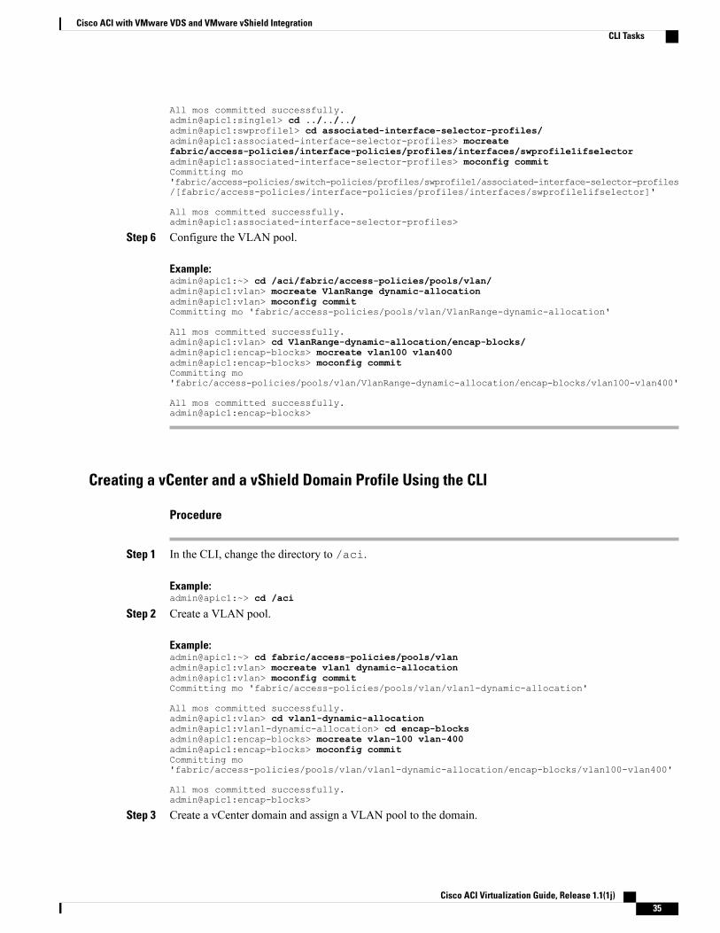
All mos committed successfully.admin@apic1:single1> cd ../../../admin@apic1:swprofile1> cd associated-interface-selector-profiles/admin@apic1:associated-interface-selector-profiles> mocreatefabric/access-policies/interface-policies/profiles/interfaces/swprofile1ifselectoradmin@apic1:associated-interface-selector-profiles> moconfig commitCommitting mo'fabric/access-policies/switch-policies/profiles/swprofile1/associated-interface-selector-profiles/[fabric/access-policies/interface-policies/profiles/interfaces/swprofile1ifselector]'
All mos committed successfully.admin@apic1:associated-interface-selector-profiles>
Step 6 Configure the VLAN pool.
Example:admin@apic1:~> cd /aci/fabric/access-policies/pools/vlan/admin@apic1:vlan> mocreate VlanRange dynamic-allocationadmin@apic1:vlan> moconfig commitCommitting mo 'fabric/access-policies/pools/vlan/VlanRange-dynamic-allocation'
All mos committed successfully.admin@apic1:vlan> cd VlanRange-dynamic-allocation/encap-blocks/admin@apic1:encap-blocks> mocreate vlan100 vlan400admin@apic1:encap-blocks> moconfig commitCommitting mo'fabric/access-policies/pools/vlan/VlanRange-dynamic-allocation/encap-blocks/vlan100-vlan400'
All mos committed successfully.admin@apic1:encap-blocks>
Creating a vCenter and a vShield Domain Profile Using the CLI
Procedure
Step 1 In the CLI, change the directory to /aci.
Example:admin@apic1:~> cd /aci
Step 2 Create a VLAN pool.
Example:admin@apic1:~> cd fabric/access-policies/pools/vlanadmin@apic1:vlan> mocreate vlan1 dynamic-allocationadmin@apic1:vlan> moconfig commitCommitting mo 'fabric/access-policies/pools/vlan/vlan1-dynamic-allocation'
All mos committed successfully.admin@apic1:vlan> cd vlan1-dynamic-allocationadmin@apic1:vlan1-dynamic-allocation> cd encap-blocksadmin@apic1:encap-blocks> mocreate vlan-100 vlan-400admin@apic1:encap-blocks> moconfig commitCommitting mo'fabric/access-policies/pools/vlan/vlan1-dynamic-allocation/encap-blocks/vlan100-vlan400'
All mos committed successfully.admin@apic1:encap-blocks>
Step 3 Create a vCenter domain and assign a VLAN pool to the domain.
Cisco ACI Virtualization Guide, Release 1.1(1j) 35
Cisco ACI with VMware VDS and VMware vShield IntegrationCLI Tasks
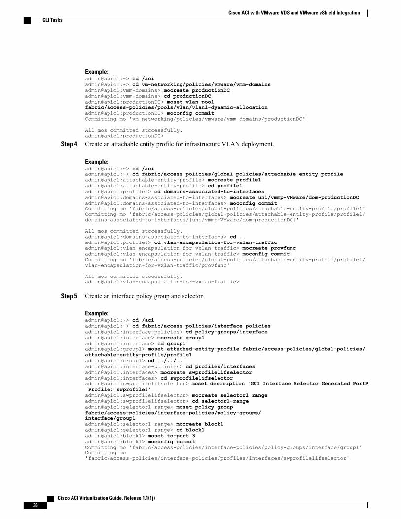
Example:admin@apic1:~> cd /aciadmin@apic1:~> cd vm-networking/policies/vmware/vmm-domainsadmin@apic1:vmm-domains> mocreate productionDCadmin@apic1:vmm-domains> cd productionDCadmin@apic1:productionDC> moset vlan-poolfabric/access-policies/pools/vlan/vlan1-dynamic-allocationadmin@apic1:productionDC> moconfig commitCommitting mo 'vm-networking/policies/vmware/vmm-domains/productionDC'
All mos committed successfully.admin@apic1:productionDC>
Step 4 Create an attachable entity profile for infrastructure VLAN deployment.
Example:admin@apic1:~> cd /aciadmin@apic1:~> cd fabric/access-policies/global-policies/attachable-entity-profileadmin@apic1:attachable-entity-profile> mocreate profile1admin@apic1:attachable-entity-profile> cd profile1admin@apic1:profile1> cd domains-associated-to-interfacesadmin@apic1:domains-associated-to-interfaces> mocreate uni/vmmp-VMware/dom-productionDCadmin@apic1:domains-associated-to-interfaces> moconfig commitCommitting mo 'fabric/access-policies/global-policies/attachable-entity-profile/profile1'Committing mo 'fabric/access-policies/global-policies/attachable-entity-profile/profile1/domains-associated-to-interfaces/[uni/vmmp-VMware/dom-productionDC]'
All mos committed successfully.admin@apic1:domains-associated-to-interfaces> cd ..admin@apic1:profile1> cd vlan-encapsulation-for-vxlan-trafficadmin@apic1:vlan-encapsulation-for-vxlan-traffic> mocreate provfuncadmin@apic1:vlan-encapsulation-for-vxlan-traffic> moconfig commitCommitting mo 'fabric/access-policies/global-policies/attachable-entity-profile/profile1/vlan-encapsulation-for-vxlan-traffic/provfunc'
All mos committed successfully.admin@apic1:vlan-encapsulation-for-vxlan-traffic>
Step 5 Create an interface policy group and selector.
Example:admin@apic1:~> cd /aciadmin@apic1:~> cd fabric/access-policies/interface-policiesadmin@apic1:interface-policies> cd policy-groups/interfaceadmin@apic1:interface> mocreate group1admin@apic1:interface> cd group1admin@apic1:group1> moset attached-entity-profile fabric/access-policies/global-policies/attachable-entity-profile/profile1admin@apic1:group1> cd ../../..admin@apic1:interface-policies> cd profiles/interfacesadmin@apic1:interfaces> mocreate swprofile1ifselectoradmin@apic1:interfaces> cd swprofile1ifselectoradmin@apic1:swprofile1ifselector> moset description 'GUI Interface Selector Generated PortPProfile: swprofile1'admin@apic1:swprofile1ifselector> mocreate selector1 rangeadmin@apic1:swprofile1ifselector> cd selector1-rangeadmin@apic1:selector1-range> moset policy-groupfabric/access-policies/interface-policies/policy-groups/interface/group1admin@apic1:selector1-range> mocreate block1admin@apic1:selector1-range> cd block1admin@apic1:block1> moset to-port 3admin@apic1:block1> moconfig commitCommitting mo 'fabric/access-policies/interface-policies/policy-groups/interface/group1'Committing mo'fabric/access-policies/interface-policies/profiles/interfaces/swprofile1ifselector'
Cisco ACI Virtualization Guide, Release 1.1(1j)36
Cisco ACI with VMware VDS and VMware vShield IntegrationCLI Tasks
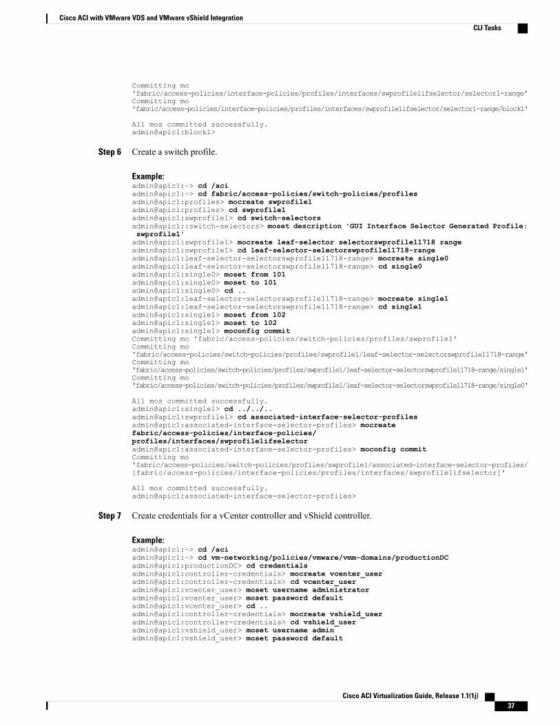
Committing mo'fabric/access-policies/interface-policies/profiles/interfaces/swprofile1ifselector/selector1-range'Committing mo'fabric/access-policies/interface-policies/profiles/interfaces/swprofile1ifselector/selector1-range/block1'
All mos committed successfully.admin@apic1:block1>
Step 6 Create a switch profile.
Example:admin@apic1:~> cd /aciadmin@apic1:~> cd fabric/access-policies/switch-policies/profilesadmin@apic1:profiles> mocreate swprofile1admin@apic1:profiles> cd swprofile1admin@apic1:swprofile1> cd switch-selectorsadmin@apic1::switch-selectors> moset description 'GUI Interface Selector Generated Profile:swprofile1'admin@apic1:swprofile1> mocreate leaf-selector selectorswprofile11718 rangeadmin@apic1:swprofile1> cd leaf-selector-selectorswprofile11718-rangeadmin@apic1:leaf-selector-selectorswprofile11718-range> mocreate single0admin@apic1:leaf-selector-selectorswprofile11718-range> cd single0admin@apic1:single0> moset from 101admin@apic1:single0> moset to 101admin@apic1:single0> cd ..admin@apic1:leaf-selector-selectorswprofile11718-range> mocreate single1admin@apic1:leaf-selector-selectorswprofile11718-range> cd single1admin@apic1:single1> moset from 102admin@apic1:single1> moset to 102admin@apic1:single1> moconfig commitCommitting mo 'fabric/access-policies/switch-policies/profiles/swprofile1'Committing mo'fabric/access-policies/switch-policies/profiles/swprofile1/leaf-selector-selectorswprofile11718-range'Committing mo'fabric/access-policies/switch-policies/profiles/swprofile1/leaf-selector-selectorswprofile11718-range/single1'Committing mo'fabric/access-policies/switch-policies/profiles/swprofile1/leaf-selector-selectorswprofile11718-range/single0'
All mos committed successfully.admin@apic1:single1> cd ../../..admin@apic1:swprofile1> cd associated-interface-selector-profilesadmin@apic1:associated-interface-selector-profiles> mocreatefabric/access-policies/interface-policies/profiles/interfaces/swprofile1ifselectoradmin@apic1:associated-interface-selector-profiles> moconfig commitCommitting mo'fabric/access-policies/switch-policies/profiles/swprofile1/associated-interface-selector-profiles/[fabric/access-policies/interface-policies/profiles/interfaces/swprofile1ifselector]'
All mos committed successfully.admin@apic1:associated-interface-selector-profiles>
Step 7 Create credentials for a vCenter controller and vShield controller.
Example:admin@apic1:~> cd /aciadmin@apic1:~> cd vm-networking/policies/vmware/vmm-domains/productionDCadmin@apic1:productionDC> cd credentialsadmin@apic1:controller-credentials> mocreate vcenter_useradmin@apic1:controller-credentials> cd vcenter_useradmin@apic1:vcenter_user> moset username administratoradmin@apic1:vcenter_user> moset password defaultadmin@apic1:vcenter_user> cd ..admin@apic1:controller-credentials> mocreate vshield_useradmin@apic1:controller-credentials> cd vshield_useradmin@apic1:vshield_user> moset username adminadmin@apic1:vshield_user> moset password default
Cisco ACI Virtualization Guide, Release 1.1(1j) 37
Cisco ACI with VMware VDS and VMware vShield IntegrationCLI Tasks
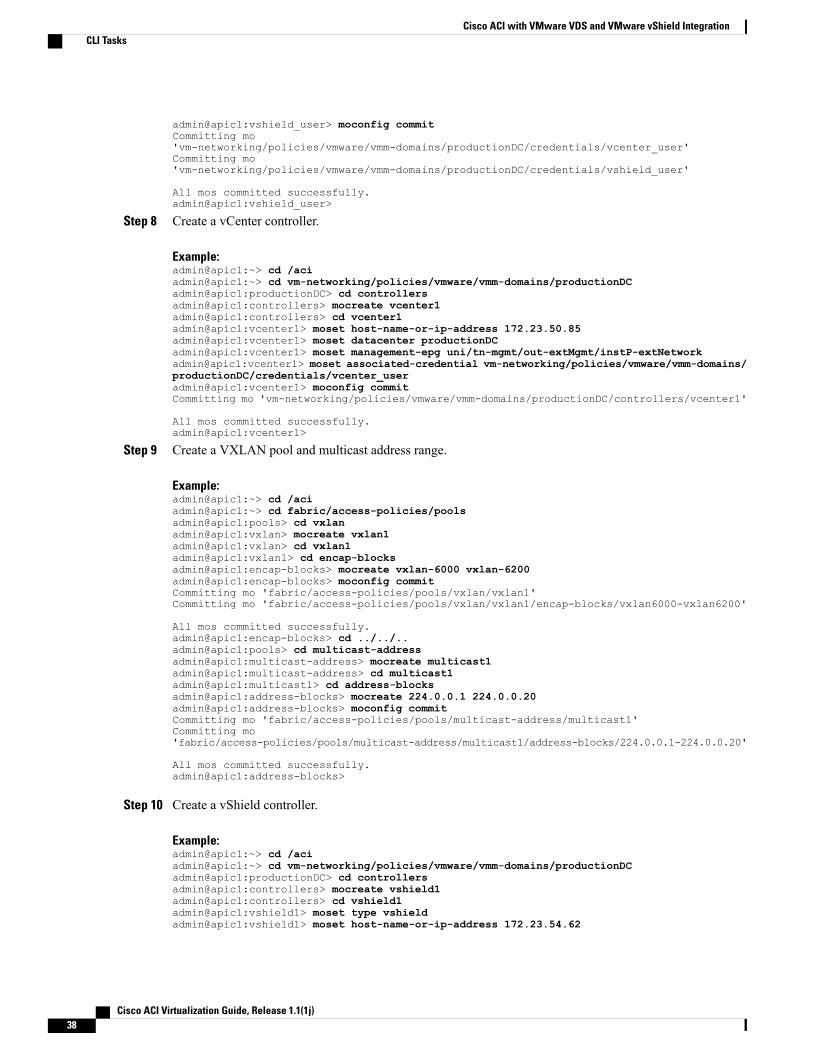
admin@apic1:vshield_user> moconfig commitCommitting mo'vm-networking/policies/vmware/vmm-domains/productionDC/credentials/vcenter_user'Committing mo'vm-networking/policies/vmware/vmm-domains/productionDC/credentials/vshield_user'
All mos committed successfully.admin@apic1:vshield_user>
Step 8 Create a vCenter controller.
Example:admin@apic1:~> cd /aciadmin@apic1:~> cd vm-networking/policies/vmware/vmm-domains/productionDCadmin@apic1:productionDC> cd controllersadmin@apic1:controllers> mocreate vcenter1admin@apic1:controllers> cd vcenter1admin@apic1:vcenter1> moset host-name-or-ip-address 172.23.50.85admin@apic1:vcenter1> moset datacenter productionDCadmin@apic1:vcenter1> moset management-epg uni/tn-mgmt/out-extMgmt/instP-extNetworkadmin@apic1:vcenter1> moset associated-credential vm-networking/policies/vmware/vmm-domains/productionDC/credentials/vcenter_useradmin@apic1:vcenter1> moconfig commitCommitting mo 'vm-networking/policies/vmware/vmm-domains/productionDC/controllers/vcenter1'
All mos committed successfully.admin@apic1:vcenter1>
Step 9 Create a VXLAN pool and multicast address range.
Example:admin@apic1:~> cd /aciadmin@apic1:~> cd fabric/access-policies/poolsadmin@apic1:pools> cd vxlanadmin@apic1:vxlan> mocreate vxlan1admin@apic1:vxlan> cd vxlan1admin@apic1:vxlan1> cd encap-blocksadmin@apic1:encap-blocks> mocreate vxlan-6000 vxlan-6200admin@apic1:encap-blocks> moconfig commitCommitting mo 'fabric/access-policies/pools/vxlan/vxlan1'Committing mo 'fabric/access-policies/pools/vxlan/vxlan1/encap-blocks/vxlan6000-vxlan6200'
All mos committed successfully.admin@apic1:encap-blocks> cd ../../..admin@apic1:pools> cd multicast-addressadmin@apic1:multicast-address> mocreate multicast1admin@apic1:multicast-address> cd multicast1admin@apic1:multicast1> cd address-blocksadmin@apic1:address-blocks> mocreate 224.0.0.1 224.0.0.20admin@apic1:address-blocks> moconfig commitCommitting mo 'fabric/access-policies/pools/multicast-address/multicast1'Committing mo'fabric/access-policies/pools/multicast-address/multicast1/address-blocks/224.0.0.1-224.0.0.20'
All mos committed successfully.admin@apic1:address-blocks>
Step 10 Create a vShield controller.
Example:admin@apic1:~> cd /aciadmin@apic1:~> cd vm-networking/policies/vmware/vmm-domains/productionDCadmin@apic1:productionDC> cd controllersadmin@apic1:controllers> mocreate vshield1admin@apic1:controllers> cd vshield1admin@apic1:vshield1> moset type vshieldadmin@apic1:vshield1> moset host-name-or-ip-address 172.23.54.62
Cisco ACI Virtualization Guide, Release 1.1(1j)38
Cisco ACI with VMware VDS and VMware vShield IntegrationCLI Tasks
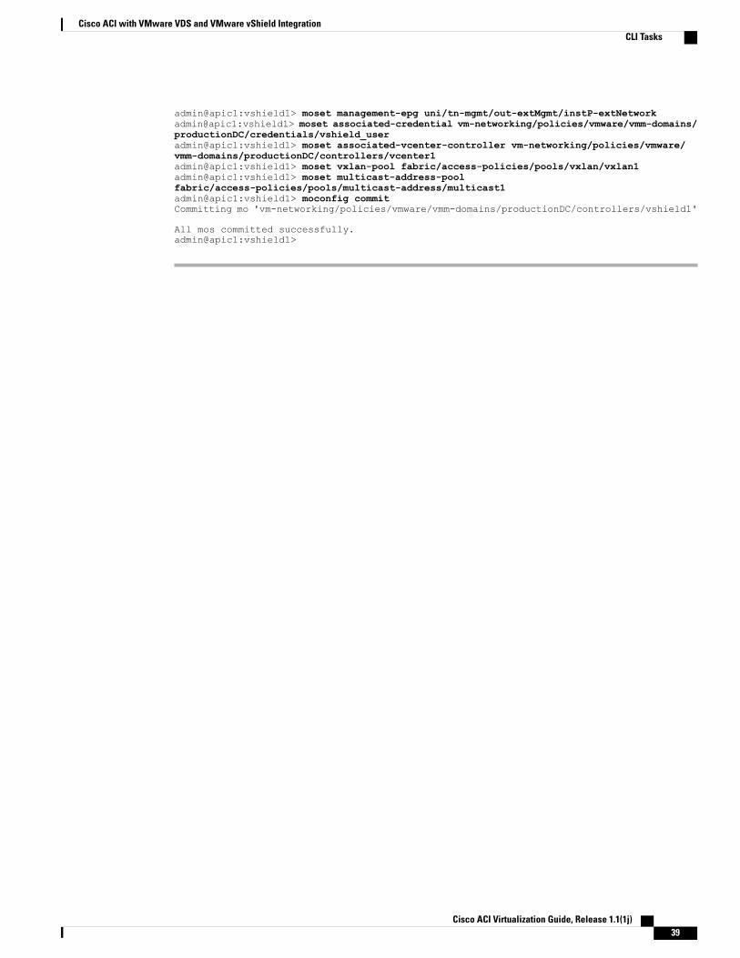
admin@apic1:vshield1> moset management-epg uni/tn-mgmt/out-extMgmt/instP-extNetworkadmin@apic1:vshield1> moset associated-credential vm-networking/policies/vmware/vmm-domains/productionDC/credentials/vshield_useradmin@apic1:vshield1> moset associated-vcenter-controller vm-networking/policies/vmware/vmm-domains/productionDC/controllers/vcenter1admin@apic1:vshield1> moset vxlan-pool fabric/access-policies/pools/vxlan/vxlan1admin@apic1:vshield1> moset multicast-address-poolfabric/access-policies/pools/multicast-address/multicast1admin@apic1:vshield1> moconfig commitCommitting mo 'vm-networking/policies/vmware/vmm-domains/productionDC/controllers/vshield1'
All mos committed successfully.admin@apic1:vshield1>
Cisco ACI Virtualization Guide, Release 1.1(1j) 39
Cisco ACI with VMware VDS and VMware vShield IntegrationCLI Tasks

Cisco ACI Virtualization Guide, Release 1.1(1j)40
Cisco ACI with VMware VDS and VMware vShield IntegrationCLI Tasks
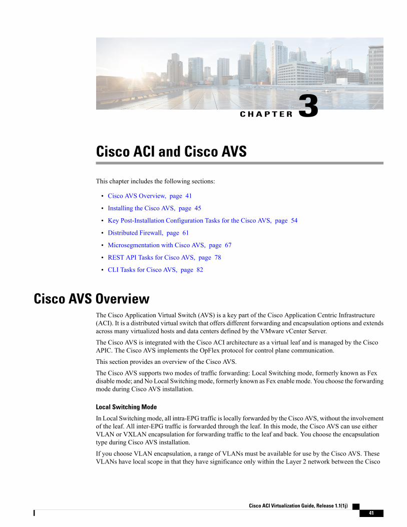
C H A P T E R 3Cisco ACI and Cisco AVS
This chapter includes the following sections:
• Cisco AVS Overview, page 41
• Installing the Cisco AVS, page 45
• Key Post-Installation Configuration Tasks for the Cisco AVS, page 54
• Distributed Firewall, page 61
• Microsegmentation with Cisco AVS, page 67
• REST API Tasks for Cisco AVS, page 78
• CLI Tasks for Cisco AVS, page 82
Cisco AVS OverviewThe Cisco Application Virtual Switch (AVS) is a key part of the Cisco Application Centric Infrastructure(ACI). It is a distributed virtual switch that offers different forwarding and encapsulation options and extendsacross many virtualized hosts and data centers defined by the VMware vCenter Server.
The Cisco AVS is integrated with the Cisco ACI architecture as a virtual leaf and is managed by the CiscoAPIC. The Cisco AVS implements the OpFlex protocol for control plane communication.
This section provides an overview of the Cisco AVS.
The Cisco AVS supports two modes of traffic forwarding: Local Switching mode, formerly known as Fexdisable mode; and No Local Switchingmode, formerly known as Fex enable mode. You choose the forwardingmode during Cisco AVS installation.
Local Switching Mode
In Local Switching mode, all intra-EPG traffic is locally forwarded by the Cisco AVS, without the involvementof the leaf. All inter-EPG traffic is forwarded through the leaf. In this mode, the Cisco AVS can use eitherVLAN or VXLAN encapsulation for forwarding traffic to the leaf and back. You choose the encapsulationtype during Cisco AVS installation.
If you choose VLAN encapsulation, a range of VLANs must be available for use by the Cisco AVS. TheseVLANs have local scope in that they have significance only within the Layer 2 network between the Cisco
Cisco ACI Virtualization Guide, Release 1.1(1j) 41
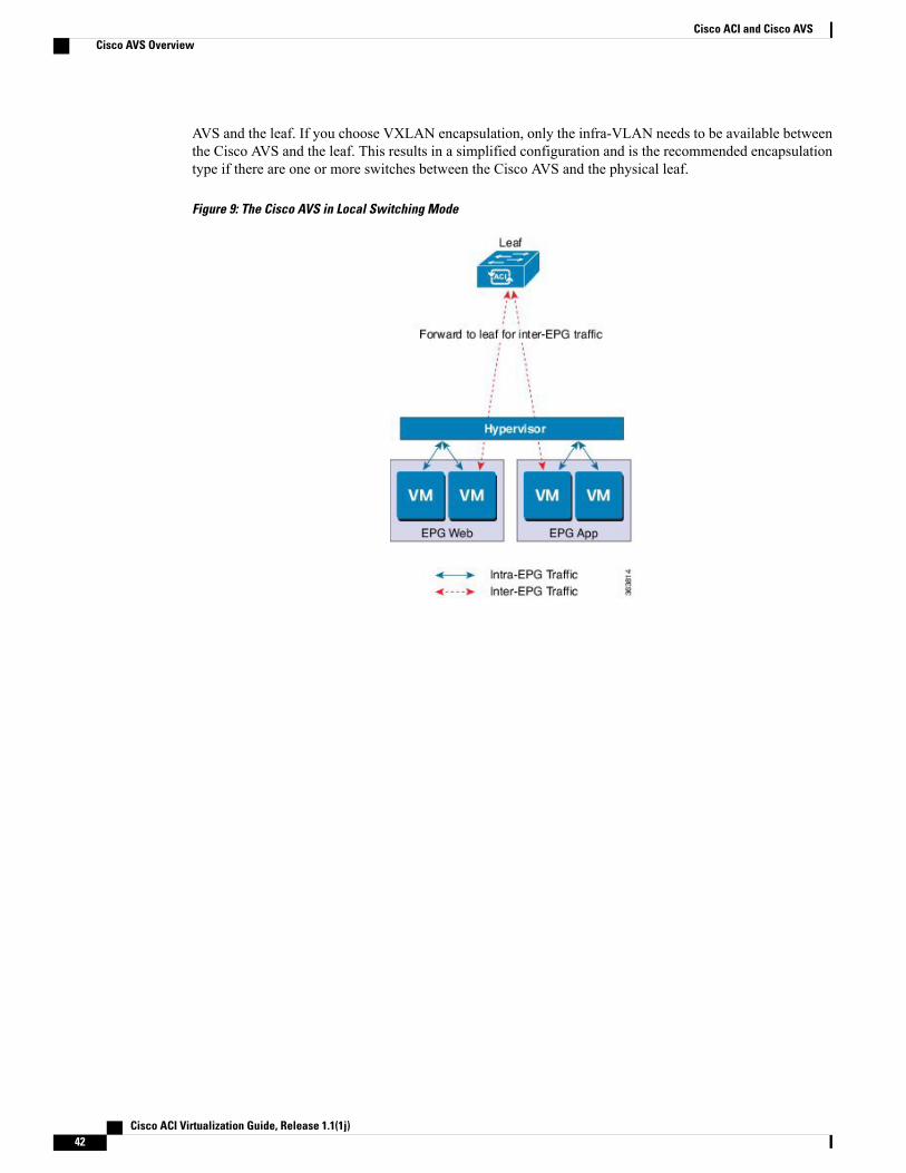
AVS and the leaf. If you choose VXLAN encapsulation, only the infra-VLAN needs to be available betweenthe Cisco AVS and the leaf. This results in a simplified configuration and is the recommended encapsulationtype if there are one or more switches between the Cisco AVS and the physical leaf.
Figure 9: The Cisco AVS in Local Switching Mode
Cisco ACI Virtualization Guide, Release 1.1(1j)42
Cisco ACI and Cisco AVSCisco AVS Overview
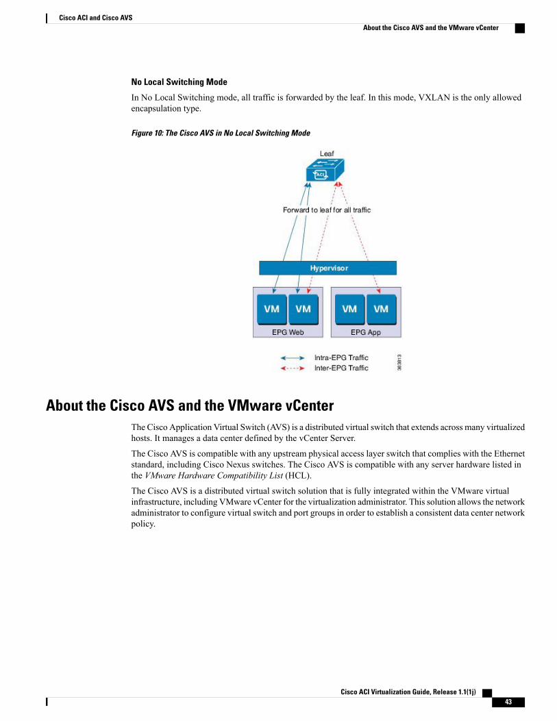
No Local Switching Mode
In No Local Switching mode, all traffic is forwarded by the leaf. In this mode, VXLAN is the only allowedencapsulation type.
Figure 10: The Cisco AVS in No Local Switching Mode
About the Cisco AVS and the VMware vCenterThe Cisco Application Virtual Switch (AVS) is a distributed virtual switch that extends across many virtualizedhosts. It manages a data center defined by the vCenter Server.
The Cisco AVS is compatible with any upstream physical access layer switch that complies with the Ethernetstandard, including Cisco Nexus switches. The Cisco AVS is compatible with any server hardware listed inthe VMware Hardware Compatibility List (HCL).
The Cisco AVS is a distributed virtual switch solution that is fully integrated within the VMware virtualinfrastructure, including VMware vCenter for the virtualization administrator. This solution allows the networkadministrator to configure virtual switch and port groups in order to establish a consistent data center networkpolicy.
Cisco ACI Virtualization Guide, Release 1.1(1j) 43
Cisco ACI and Cisco AVSAbout the Cisco AVS and the VMware vCenter
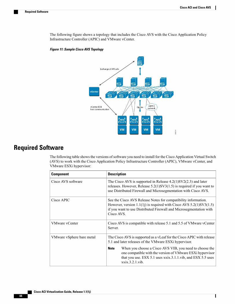
The following figure shows a topology that includes the Cisco AVS with the Cisco Application PolicyInfrastructure Controller (APIC) and VMware vCenter.
Figure 11: Sample Cisco AVS Topology
Required SoftwareThe following table shows the versions of software you need to install for the Cisco Application Virtual Switch(AVS) to work with the Cisco Application Policy Infrastructure Controller (APIC), VMware vCenter, andVMware ESXi hypervisor:
DescriptionComponent
The Cisco AVS is supported in Release 4.2(1)SV2(2.3) and laterreleases. However, Release 5.2(1)SV3(1.5) is required if you want touse Distributed Firewall and Microsegmentation with Cisco AVS.
Cisco AVS software
See the Cisco AVS Release Notes for compatibility information.However, version 1.1(1j) is required with Cisco AVS 5.2(1)SV3(1.5)if you want to use Distributed Firewall and Microsegmentation withCisco AVS.
Cisco APIC
Cisco AVS is compatible with release 5.1 and 5.5 of VMware vCenterServer.
VMware vCenter
The Cisco AVS is supported as a vLeaf for the Cisco APICwith release5.1 and later releases of the VMware ESXi hypervisor.
When you choose a Cisco AVS VIB, you need to choose theone compatible with the version of VMware ESXi hypervisorthat you use. ESX 5.1 uses xxix.3.1.1.vib, and ESX 5.5 usesxxix.3.2.1.vib.
Note
VMware vSphere bare metal
Cisco ACI Virtualization Guide, Release 1.1(1j)44
Cisco ACI and Cisco AVSRequired Software
DescriptionComponent
The Cisco AVS is supported in VSUM Release 1.0 and later releases.Cisco Virtual Switch UpdateManager (VSUM)
Cisco AVS DocumentationYou can find documentation on the Cisco Application Virtual Switch page on Cisco.com.
Documentation for Cisco Application Virtual Switch (AVS) includes:
• Cisco Application Virtual Switch Release Notes
• Cisco Application Virtual Switch Documentation Overview
• Cisco Application Virtual Switch Installation Guide
• Cisco Application Virtual Switch Download Instructions for VMware ESXi Deployments
• Cisco Application Virtual Switch Configuration Guide
• Cisco Application Virtual Switch Verified Scalability Guide
• Cisco Application Virtual Switch Solution Guide
• Cisco Application Virtual Switch Troubleshooting Guide
• Cisco Virtual Switch Update Manager Getting Started Guide
• Cisco Virtual Switch Update Manager Release Notes
• Cisco Virtual Switch Update Manager Troubleshooting Guide
Installing the Cisco AVSInstalling the Cisco Application Virtual Switch (AVS) consists of two separate sets of tasks: configuring theCisco Application Policy Infrastructure Controller (APIC) and then using the Cisco Virtual Switch UpdateManager (VSUM) to install Cisco AVS onto the ESXi host and add the ESXi host to the Cisco AVS. Youalso must verify the installation.
This section provides the instructions for each set of tasks that you need to perform to install the Cisco AVSto use within the Cisco Application Centric Infrastructure (ACI) fabric.
Prerequisites for Installing the Cisco AVSYou need to perform the following tasks before installing the Cisco Application Virtual Switch (AVS).
• You must set up the Cisco Application Policy Infrastructure Controller (APIC) before you can set upthe Cisco AVS. See the Cisco APIC Getting Started Guide for instructions on how to configure theCisco APIC for the first time.
Cisco ACI Virtualization Guide, Release 1.1(1j) 45
Cisco ACI and Cisco AVSCisco AVS Documentation
• Youmust make sure that all switches are registered and that the Cisco Application Centric Infrastructure(ACI) fabric is up to date. See Cisco Application Centric Infrastructure Fundamentals and the CiscoAPIC Getting Started Guide.
• You must install the Cisco Virtual Switch Update Manager (VSUM). See the Cisco Virtual SwitchUpdate Manager Getting Started Guide.
Workflow for Installing the Cisco AVSThis section provides a high-level description of the tasks that you need to perform in order to install the CiscoApplication Virtual Switch (AVS).
1 Create interface and switch policies and a VMware vCenter domain profile for the Cisco AVS in theunified configuration wizard in the Cisco Application Policy Infrastructure Controller (APIC) GUI.
An interface policy configures the type of interface—port channel (PC) or virtual PC (VPC)—for thevSphere hosts and a link aggregation control protocol (LACP), or MAC pinning. See the appendix"Recommended Topologies" in the Cisco Application Virtual Switch Installation Guide for supportedtopologies.
A switch policy configures the connection between the Cisco AVS (the vLeaf) and the ESXi hypervisorby specifying a physical port on the leaf switch and by specifying Cisco AVS trunk settings. These includeVLANs or VXLANs.
A VMware vCenter domain groups virtual machine (VM) controllers with similar networking policyrequirements. For example, VM controllers can share VLAN or Virtual Extensible Local Area Network(VXLAN) space and application endpoint groups (EPGs). The CiscoAPIC communicateswith the controllerto publish network configurations such as port groups that are then applied to the virtual workloads.
See the section Creating Interface and Switch Profiles and a vCenter Domain Profile Using the GUI inthis guide for instructions.
2 Install the Cisco AVS and add the ESXi host to the Cisco AVS using the Cisco Virtual Switch UpdateManager (VSUM).
Using Cisco VSUM is the recommended method for installing the Cisco AVS. Using Cisco VSUMvalidates the version and compatibility for the ESXi host, and in one procedure enables you to install theCisco AVS onto the ESXi host and add the ESXi host to the Cisco AVS distributed virtual switch (DVS).
See the section Completion of the Cisco AVS Installation in the VSUM in this guide for instructions forinstalling the Cisco AVS using VSUM.
3 Verify the Cisco AVS Installation.
You need to verify that the Cisco AVS has been installed on the VMware ESXi hypervisor by verifyingthe virtual switch status and the virtual NIC status. You also need to verify that the vmknic is created, thatOpFlex is online, and that the ports are in a forwarding state.
See the section Verifying the Cisco AVS Installation in this guide for instructions.
Creating Interface, Switch, and Center Domain ProfilesBefore you can install the Cisco Application Virtual Switch (AVS), you need to create interface, switch, andvCenter domain profiles. As of Cisco Application Policy Infrastructure Controller (APIC) 1.1.x, we recommend
Cisco ACI Virtualization Guide, Release 1.1(1j)46
Cisco ACI and Cisco AVSWorkflow for Installing the Cisco AVS
that you perform these tasks in the united configuration wizard in the Cisco APIC. This is the procedureCreating Interface and Switch Profiles and a vCenter Domain Profile Using the GUI in this guide.
You should understand and follow the guidelines in this section before proceeding with the tasks.
Alternate Procedures
If you need to configure a FEX profile or detailed interface, switch, or vCenter domain profiles, you can findinstructions in Appendix C, "Procedures for Creating Interface, Switch, and vCenter Domain Profiles" in theCisco Application Virtual Switch Installation Guide.
Firewall Considerations
If you use the recommended united configuration wizard, the Cisco APIC automatically creates a firewallpolicy, which can be modified later. If you instead use the alternate procedures to create interface, switch, orvCenter domain profiles, you will need to create a firewall policy manually. Follow the instructions in theDistributed Firewall section of this guide.
Interface and Switch Profile Guidelines and PrerequisitesFollow these guidelines and fulfil the prerequisites when creating interface and switch profiles for your CiscoApplication Virtual Switch (AVS).
Guidelines for Creating Interface and Switch Profiles
The Cisco AVS supports PC, VPC, MAC Pinning, and FEX interface policies. It does not support individualinterface policies. See the Cisco Application Virtual Switch Installation Guide for information about FEXpolicies.
• If there is a Layer 2 network between the leaf switch and the Cisco AVS vSphere host, configure theinterface policy on the interfaces that are connected to the Layer 2 network.
• The number of links and leafs that you use determine whether you need to configure a PC or a virtualport channel (VPC) policy for the Cisco AVS:
◦If you are using a single link between a leaf and an ESXi host, you need to configure a PC policy.
◦If you are using multiple links between one leaf and an ESXi host, you must configure a PC policy.
◦If you are using multiple links between multiple leafs and an ESXi host, you must configure aVPC policy.
• Follow these guidelines for choosing a link aggregation control protocol (LACP) policy:
◦Choose LACP (Active/Passive) if the uplinks from the Cisco AVS (vSphere host) are directlyconnected to the leaf switches and you want to use or turn on the LACP channeling protocol.
◦Choose LACP (Off) if the uplinks form the Cisco AVS are directly connected to the leaf switchesbut you do not want to use the LACP channeling protocol, for example, static port channel.
◦Choose MAC pinning if the uplinks from the Cisco AVS should not be channeled together andwill operate as separate links.
Cisco ACI Virtualization Guide, Release 1.1(1j) 47
Cisco ACI and Cisco AVSCreating Interface, Switch, and Center Domain Profiles
Prerequisites for Creating Interface and Switch Profiles
You should verify that the leaf switch interfaces are physically connected to the ESXi hypervisor or, if youare using a Layer 2 device, verify that the leaf is physically connected to the Layer 2 device.
vCenter Domain Profile Guidelines and PrerequisitesYou must create a new vCenter domain profile; you cannot convert an existing one. For information aboutdeleting an existing VMware vCenter domain profile, see the section "Guidelines for Deleting VMMDomains"in Cisco Application Centric Infrastructure Fundamentals.
Guidelines for Creating a VMware vCenter Domain Profile
You can create multiple data centers and Distributed Virtual Switch (DVS) entries under a single domain.However, you can have only one Cisco Application Virtual Switch (AVS) assigned to each data center.
If you choose VXLAN encapsulation and MAC pinning link aggregation, we recommend that you enableVXLAN load balancing. See the section “Enabling VXLAN load balancing” in the Cisco Application VirtualSwitch Configuration Guide.
If VXLAN load balancing is enabled in the VMware vCenter domain profile, Microsegmentation withCisco AVS cannot be enabled on the domain.
Note
Prerequisites for Creating a VMware vCenter Domain Profile
Make sure that the multicast IP address pool has enough multicast IP addresses to accommodate the numberof EPGs that will be published to the VMware vCenter domain. You can add more IP addresses to a multicastaddress pool that is already associated with a VMware vCenter domain at any time.
Make sure that you have a sufficient number of VLAN IDs. If you do not, ports on endpoint groups (EPGs)might report that no encapsulation is available.
If you want to change the switch mode on a Cisco AVS, you first must remove the existing DVS and thenadd the VMware vCenter domain with the desired switching mode. For instructions on removing the existingDVS, see Cisco Application Virtual Switch Configuration Guide.
vCenter must be installed, configured, and reachable through the in-band/out-of-band management network.
You must have the administrator/root credentials to the vCenter.
If you prefer not to use the vCenter administrator/root credentials, you can create a custom user accountwith minimum required permissions. See Custom User Account with Minimum VMware vCenterPrivileges, on page 25 for a list of the required user privileges.
Note
Creating Interface and Switch Profiles and a vCenter Domain Profile Using the GUI
Before You Begin
Before you create a vCenter domain profile, you must establish connectivity to external network using in-bandmanagement network on the Cisco Application Policy Infrastructure Controller (APIC).
Cisco ACI Virtualization Guide, Release 1.1(1j)48
Cisco ACI and Cisco AVSCreating Interface, Switch, and Center Domain Profiles
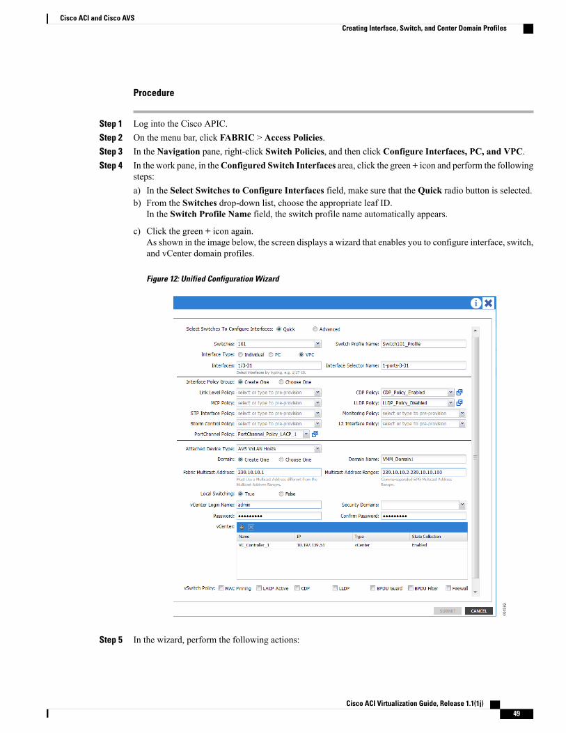
Procedure
Step 1 Log into the Cisco APIC.Step 2 On the menu bar, click FABRIC > Access Policies.Step 3 In the Navigation pane, right-click Switch Policies, and then click Configure Interfaces, PC, and VPC.Step 4 In the work pane, in theConfigured Switch Interfaces area, click the green + icon and perform the following
steps:a) In the Select Switches to Configure Interfaces field, make sure that the Quick radio button is selected.b) From the Switches drop-down list, choose the appropriate leaf ID.
In the Switch Profile Name field, the switch profile name automatically appears.
c) Click the green + icon again.As shown in the image below, the screen displays a wizard that enables you to configure interface, switch,and vCenter domain profiles.
Figure 12: Unified Configuration Wizard
Step 5 In the wizard, perform the following actions:
Cisco ACI Virtualization Guide, Release 1.1(1j) 49
Cisco ACI and Cisco AVSCreating Interface, Switch, and Center Domain Profiles
a) In the Interface Type field, choose the appropriate radio button.PC or VPC are the only valid options for Cisco AVS deployment. See the section Interface and SwitchProfile Guidelines and Prerequisites in this guide.
b) In the Interfaces field, enter the interface or interface range for your vSphere hosts.Once you enter the interface or interface range, the wizard enters a name in the Interface Selector Namefield.
c) In the Interface Policy Group Field, choose the Create One radio button.This procedure assumes that you are creating interface and switch policies and creating a vCenterdomain from scratch. If you choose the Choose One radio button, you will not be able to do soin the wizard.
Note
d) From the CDP Policy or the LLDP Policy drop-down list, create a policy.If you use a Cisco Unified Computing System (UCS) server, create a policy to enable a CiscoDiscovery Protocol (CDP) policy and a policy to disable Link Layer Discovery Protocol (LLDP).
Note
e) From the Link Level Policy drop-down list, choose the desired link level policy or create one.The link level policy specifies the speed of the physical interface. If you do not choose a link level policy,the speed will default to 10 Gbps.
f) In the Port Channel Policy drop-down list, choose Create Port Channel Policy.You need to choose the same policy that is on the ESXi server. For example, if the server does not supportLACP, you can choose Static Channel - Mode On orMAC Pinning.
g) In the Attached Device Type field, choose AVS VLAN Hosts or AVS VXLAN Hosts.h) Make sure that the Create One radio button is chosen. This option is used when creating a new VMM
domain for an interface or switch profile, as you do in this procedure.The Choose One button is used when creating an interface or switch profile for a new host that you wantto make part of an existing VMM domain.
i) In the Domain Name field, enter the domain name.j) If you chose AVS VLAN Hosts in Step 5 g, in the VLAN Range field, enter the VLAN range as
appropriate.Do not define a range that includes the reserved VLAN ID for infrastructure network becausethat VLAN is for internal use.
Note
k) If you chose AVS VXLAN Hosts in Step 5 g, in theMulticast Address field, enter an address, such as225.1.1.1.
l) If you chose AVS VXLANHosts in Step 5 g, in theMulticast Address Ranges field, enter a range, suchas 225.0.0.50-225.0.0.100.
The multicast address configured in Step 5 k must not overlap with the ranges configured in Step5 l.
Note
m) If you chose AVS VXLAN Hosts in Step 5 g, in the Local Switching area, choose True or False.With local switching, traffic within an endpoint group (EPG) does not go to the leaf, so if you choose localswitching, you might not see some traffic counters. If you want to see all intra-EPG traffic, you shouldchoose False. See the section Cisco AVS Overview at the start of this chapter for additional informationabout Local Switching and No Local Switching modes.
n) (Optional) From the Security Domains drop-down list, choose or create a security domain.o) In the vCenter Login Name field, enter the vCenter Administrator/root username.p) In the Password field, enter the vCenter Administrator/root password.q) In the Confirm Password field, reenter the password.
Step 6 Click the + icon to expand vCenter, and in the Create vCenter/vShield Controller dialog box, perform thefollowing actions:
Cisco ACI Virtualization Guide, Release 1.1(1j)50
Cisco ACI and Cisco AVSCreating Interface, Switch, and Center Domain Profiles
a) In the Name field, enter a name to refer to the vCenter domain.The name does not need to be the same as the vCenter domain name; you can use the vCenter's host name.
b) In the Host Name (or IP Address) field, enter the host name or IP address.If you use the host name, you must already have configured a DNS policy on Cisco APIC. If you do nothave a DNS policy configured, enter the IP address of the vCenter server.
c) From the DVS Version drop-down list, choose DVS Version 5.1.d) In the Stats Collection field, choose the Enabled radio button.e) In the Datacenter field, enter the data center name.
The name that you enter for Datacenter must match exactly the name in vCenter. The name iscase sensitive.
Note
f) (Optional) From theManagement EPG drop-down list, choose a management EPG or create one andthen click OK.If no management EPGs is specified, the default out-of-band management policy will be used.
g) Click OK.h) In the vSwitch Policy area, check the appropriate check boxes, and then click Save.
If you do not specify a policy in the vSwitch policy area, the same interface policy that youconfigured earlier in the wizard will take effect for the vSwitch.
Note
In the vSwitch Policy area, check theMAC Pinning check box if you have a Unified ComputingSystem (UCS) Fabric Interconnect (FI) between the top-of-rack switch and the Cisco AVS.
Note
If you leave the Firewall checkbox unchecked, Distributed Firewall is configured in Enabledmode. If you check the Firewall check box, Distributed Firewall is configured in Learning mode.Distributed Firewall should be in Learning mode only before Cisco AVS is upgraded; otherwiseDistributed Firewall should be in Enabled mode.
You can change the Distributed Firewall mode later. See the section Creating a Distributed FirewallPolicy or Changing its Mode Using the GUI in this guide for instructions.
Note
Step 7 In the Configure Interface, PC, And VPC dialog box, click SAVE, click SAVE again, and then clickSUBMIT.
Step 8 Verify the new domain and profiles, by performing the following actions:a) On the menu bar, choose VM Networking > Inventory.b) In the navigation pane, expand VMware > Domain_name > Controllers, and then choose the vCenter.In the work pane, under Properties, view the virtual machine manager (VMM) domain name to verify thatthe controller is online. In the work pane, the vCenter properties are displayed including the operational status.The displayed information confirms that connection from the APIC controller to the vCenter server isestablished, and the inventory is available.
Completion of the Cisco AVS Installation in the VSUMOnce you have finished configuring the Cisco Application Virtual Switch (AVS) in the Cisco ApplicationPolicy Infrastructure Controller (APIC), you complete the installation of the Cisco AVS in the Cisco VirtualSwitch Update Manager (VSUM). You do so by installing the Cisco AVS and adding the ESXi host to theCisco AVS.
Cisco ACI Virtualization Guide, Release 1.1(1j) 51
Cisco ACI and Cisco AVSCompletion of the Cisco AVS Installation in the VSUM
Prerequisites for Installing Cisco AVSInstalling the Cisco Application Virtual Switch (AVS) using the Cisco Virtual Switch Update Manager(VSUM) has the following prerequisites:
• The Cisco AVS configuration in the Cisco Application Policy Infrastructure Controller (APIC) must becompleted manually. See the section Creating Interface, Switch, and Center Domain Profiles in thisguide or theCisco Application Virtual Switch InstallationGuide for detailed information about configuringthe Cisco APIC before Cisco AVS installation.
• You must have created a tenant configuration that contains the required bridge domain, applicationprofile, endpoint groups, and contracts. See theCisco APICGetting Started Guide for more information.
• The host must have one or more unclaimed physical NICs.
• You must have administrative privileges for vCenter Server.
Installing Cisco AVS Using VSUMThe following procedure—using the feature labeledAddHost-AVS in VSUM—puts the hosts intomaintenancemode, installs the Cisco AVS, and adds an ESXi host or multiple hosts to the Cisco AVS.
Before You Begin
You need to obtain the following information for the Cisco AVS:
• vCenter IP address
• vCenter user ID
• vCenter password
Procedure
Step 1 Log in to the VMware vSphere Web Client.Step 2 Choose Home > Cisco Virtual Switch Update Manager > AVS > Configure.Step 3 Choose a data center and the Cisco AVS and then clickManage.Step 4 In the switch pane, choose Cisco AVS > Add Host-AVS.Step 5 From the Target Version drop-down list, choose the target VIB version to be installed on the host.Step 6 Click Show Host.Step 7 In the Host Selection area, choose the hosts to be added.
The hosts are represented in the following categories:
• Cluster—Hosts that are part of clusters.
• Standalone Hosts—Hosts that are not part of clusters. You can add hosts that are standalone mode.
Hosts are further organized within the Cluster and Standalone categories:
• Supported—Hosts that are supported by the Cisco AVS. You can add these hosts.
• Unsupported—Hosts that are not supported by the Cisco AVS.
Cisco ACI Virtualization Guide, Release 1.1(1j)52
Cisco ACI and Cisco AVSCompletion of the Cisco AVS Installation in the VSUM
• Unreachable—Hosts that are in a not responding state or are in a disconnected state.
• Already in DVS—Hosts that are already associated with the DVS. You cannot add a host that is alreadyassociated with a DVS.
• No free PNIC—Hosts that do not have a free PNIC. You cannot add a host that does not have a freePNIC.
Step 8 Expand Cluster or Standalone, depending on your setup.Step 9 Choose one or more available hosts and then click Suggest.
The PNIC Selection area displays the available uplinks for each host.Step 10 In the PNIC Selection area, choose the PNIC or PNICS to be added to the Cisco AVS.Step 11 Click Finish to add the host or hosts to the Cisco AVS.Step 12 Check the status of adding the host by completing the following steps:
a) In the Recent Tasks pane to the right of the work pane, clickMore Tasks.The Task Console appears in the work pane, displaying a list of tasks with the most recent task at the top.
b) Find the task in the Task Name column and then view the status in the Status column.The Status column shows whether the task is complete or is in progress. You can click the refresh iconto display new tasks and learn how much of the task is complete in terms of percentage.
Several tasks might appear above the primary task you just performed. They might be associatedwith your primary task.
Note
The host addition is confirmed when the primary task Add hosts to Cisco DVS has the statusCompleted.
If you close the browser and later want to view the task's history, log in to the web client, click Tasks in thenavigation pane to display the lists of tasks in the work pane.
What to Do Next
You need to verify the Cisco AVS installation. See Verifying the Cisco AVS Installation in this guide forinstructions.
Verifying the Cisco AVS InstallationThe following sections describe how to verify that the Cisco Application Virtual Switch (AVS) has beeninstalled on the VMware ESXi hypervisor.
Verifying the Virtual Switch Status
Procedure
Step 1 Log in to the VMware vSphere Client.Step 2 Choose Networking.Step 3 Open the folder for the data center and click the virtual switch.Step 4 Click the Hosts tab.
Cisco ACI Virtualization Guide, Release 1.1(1j) 53
Cisco ACI and Cisco AVSCompletion of the Cisco AVS Installation in the VSUM

The VDS Status and Status fields display the virtual switch status. The VDS status should be Up to indicatethat OpFlex communication has been established.
Verifying the vNIC Status
Procedure
Step 1 In VMware vSphere Client, click the Home tab.Step 2 Choose Hosts and Clusters.Step 3 Click the host.Step 4 Click the Configuration tab.Step 5 In the Hardware panel, choose Networking.Step 6 In the View field, click the vSphere Distributed Switch button.Step 7 ClickManage Virtual Adapters. The vmk1 displays as a virtual adapter and lists an IP address.Step 8 Click the newly created vmk interface to display the vmknic status.
Allow approximately 20 seconds for the vNIC to receive an IP address through DHCP.Note
Key Post-Installation Configuration Tasks for the Cisco AVSAfter you install the Cisco Application Virtual Switch (AVS), you need to perform some configuration tasksin the Cisco Application Policy Infrastructure Controller (APIC).
Prerequisites for Configuring the Cisco AVSBefore you configure the Cisco Application Virtual Switch (AVS), you need to perform the following tasks:
1 Install the Cisco AVS as described in the previous sections of this guide.
2 Understand the concepts presented in the ACI Fundamentals Guide and the APIC Getting Started Guide.
Workflow for Key Post-Installation Configuration Tasks for the Cisco AVSThis section provides a high-level description of the tasks that you need to perform in the correct sequencein order to configure Cisco Application Virtual Switch (AVS).
1 Deploy an application profile.
a Create a tenant.
Cisco ACI Virtualization Guide, Release 1.1(1j)54
Cisco ACI and Cisco AVSKey Post-Installation Configuration Tasks for the Cisco AVS
A tenant is a logical container for application policies that enable an administrator to exercisedomain-based access control. Tenants can represent a customer in a service provider setting, anorganization or domain in an enterprise setting, or just a convenient grouping of policies.
The fabric can contain multiple tenants. Tenants can be isolated from one another or can share resources.The primary elements that the tenant contains are filters, contracts, outside networks, bridge domains,contexts, and application profiles that contain endpoint groups (EPGs). Entities in the tenant inheritits policies.
You must configure a tenant before you can deploy any Layer 4 to Layer 7 services.
See the section Creating a Tenant, Private Network, and Bridge Domain Using the GUI in this guidefor instructions for creating tenants.
b Create an application profile.
An application profile models application requirements. An application profile is a convenient logicalcontainer for grouping EPGs.
Modern applications contain multiple components. For example, an e-commerce application couldrequire a web server, a database server, data located in a storage area network, and access to outsideresources that enable financial transactions. The application profile contains as many (or as few) EPGsas necessary that are logically related to providing the capabilities of an application.
See the section Creating an Application Profile Using the GUI in this guide for instructions for creatingan application profile.
c Create an endpoint group (EPG)
Endpoints are devices that are connected to the network directly or indirectly. They have an address(identity), a location, attributes (such as version or patch level), and can be physical or virtual. Endpointexamples include servers, virtual machines, network-attached storage, or clients on the Internet.
An EPG is a named logical entity that contains a collection of endpoints that have common policyrequirements such as security, virtual machine mobility, QoS, or Layer 4 to Layer 7 services. EPGsenable you to manage endpoints as a group rather than having to configure and manage themindividually; endpoints in an EPG have the same configuration and changes to EPG configuration arepropagated automatically to all the endpoints assigned to it. In vCenter Server, an EPG is representedas a port group.
See the section Creating EPGs Using the GUI in this guide for instructions for creating EPGs.
d Assign port groups to virtual machines (VMs) in vCenter.
In vCenter Server, an EPG is represented as a port group. The virtual Ethernet (vEth) interfaces areassigned in vCenter Server to an EPG in order to do the following:
• Define the port configuration by the policy.
• Apply a single policy across a large number of ports.
EPGs that are configured as uplinks can be assigned by the server administrator to physical ports (whichcan be vmnics or PNICs). EPGs that are not configured as uplinks can be assigned to a VM virtualport.
See the section Assigning Port Groups to the VM in vCenter in this guide for instructions.
e Create filters.
Cisco ACI Virtualization Guide, Release 1.1(1j) 55
Cisco ACI and Cisco AVSWorkflow for Key Post-Installation Configuration Tasks for the Cisco AVS
A filter is a managed object that helps enable mixing and matching among EPGs and contracts so asto satisfy various applications or service delivery requirements. It specifies the data protocols to beallowed or denied by a contract—rules for communications between EPGs—that contains the filter.
See the section Creating a Filter Using the GUI in this guide for instructions.
f Create contracts.
Contracts are policies that enable communications between EPGs. An administrator uses a contract toselect the type(s) of traffic that can pass between EPGs, including the protocols and ports allowed. Ifthere is no contract, inter-EPG communication is disabled by default. No contract is required forcommunication within an EPG; communication within an EPG is always implicitly allowed.
Contracts govern the communication between EPGs that are labeled providers, consumers, or both.An EPG can both provide and consume the same contract. An EPG can also provide and consumemultiple contracts simultaneously.
See the section Creating a Contract Using the GUI in this guide for instructions.
2 Verify the application profile.
You need to perform the following tasks to verify that the application profile has been created.
a Verify the application profile on the Cisco APIC.
b Verify that the EPGs appear in the vCenter.
c Ensure that the VMs can communicate.
See the section Verifying the Application Profile and EPGs in Cisco APIC in this guide for instructions.
3 (Optional but recommended) Enable Distributed Firewall.
After you install or upgrade to Cisco AVS Release 5.2(1)SV3(1.5), you need to enable Distributed Firewallif you want to use the feature. Distributed Firewall is in Learning mode by default. Follow the instructionsin Creating a Distributed Firewall Policy or Changing its Mode Using the GUI in this guide to enableDistributed Firewall.
Deploying an Application Profile for the Cisco AVS
Creating a Tenant, Private Network, and Bridge Domain Using the GUI• To watch an example video of this task, see Videos Webpage.
• If you have a public subnet when you configure the routed outside, youmust associate the bridge domainwith the outside configuration.
Procedure
Step 1 On the menu bar, choose TENANTS, and perform the following actions:a) Click Add Tenant.
The Create Tenant dialog box opens.
Cisco ACI Virtualization Guide, Release 1.1(1j)56
Cisco ACI and Cisco AVSDeploying an Application Profile for the Cisco AVS
b) In the Name field, add the tenant name (ExampleCorp).
Step 2 Create a security domain so that it allows only users in that security domain to have access.Note
Click the + sign next to Security Domains to open the Create Security Domain dialog box, and performthe following actions:a) In the Name field, specify the security domain name. (ExampleCorp)b) Click Submit. In the Create Tenant dialog box, check the check box for the security domain that you
created, and click Next.
Step 3 In the Network window, perform the following actions:a) Click the + sign to add the network.b) In the Create New Network area, specify the private tenant network name (pvn1), and click Next.
You are prompted to specify a bridge domain in the network.
Step 4 In the Specify Bridge Domain for the Network area, perform the following actions:a) In the Name field, enter a name (bd1).b) Expand Subnets, and in the Create Subnet dialog box, in the Gateway IP field, enter the IP address.
Click OK.The Gateway Address can be an IPv4 or an IPv6 address. For more about details IPv6 gatewayaddress, see the related KB article, KB: Creating a Tenant, Private Network, and Bridge Domainwith IPv6 Neighbor Discovery .
Note
Step 5 Click OK, and perform the following actions:a) Confirm that the private network (pvn1) is created and is associated with the bridge domain (bd1).b) In the Network area, click Finish.
Step 6 To validate that the tenant has a private network and bridge domain, in the submenu bar under the Tenantstab, click the new tenant name that you created. In the Navigation pane, expand the tenant name.Under Networking > Bridge Domains, the new bridge domain is displayed. Under Private Networks, thenew network is displayed.
Creating an Application Profile Using the GUI
Procedure
Step 1 On the menu bar, choose TENANTS. In the Navigation pane, expand the tenant, right-click ApplicationProfiles, and click Create Application Profile.
Step 2 In theCreate Application Profile dialog box, in theName field, add the application profile name (OnlineStore).
Creating EPGs Using the GUIThe port the EPG uses must belong to one of the VMManagers (VMM) or physical domains associated withthe EPG.
Cisco ACI Virtualization Guide, Release 1.1(1j) 57
Cisco ACI and Cisco AVSDeploying an Application Profile for the Cisco AVS
Procedure
Step 1 Expand EPGs. In the Create Application EPG dialog box, perform the following actions:a) In the Name field, add the EPG name (db).b) In the Bridge Domain field, choose the bridge domain from the drop-down list (bd1).c) Check the Associate to VM Domain Profiles check box. Click Next.d) In the Step 2 for Specify the VM Domains area, expand Associate VM Domain Profiles and from the
drop-down list, choose the desired VMM domain. Click Update and click OK.
Step 2 In theCreate Application Profile dialog box, create two more EPGs. The three EPGs should be db, app, andweb in the same bridge domain and data center.
Assigning Port Groups to the VM in vCenter
Procedure
Step 1 Log in to the vCenter.Step 2 Navigate to the virtual machine (VM) in the navigation pane.Step 3 Right-click the VM in the navigation pane.Step 4 In the Edit Settings dialog box for the VM, complete the following actions:
a) From the Network Adapter 1 drop-down menu, choose the appropriate combined value for tenant,application profile, and endpoint group (EPG).For example, you might see an option similar to T2|ap4|EPG1 followed by the values that were configuredin Cisco APIC.
b) Repeat Step 4 a for any other network adapters you have and want to configure.You must configure one network adapter; configuring others is optional.
c) Click OK.
Creating a Filter Using the GUICreate a filter using the following steps. This task shows how to create an HTTP filter.
Before You Begin
Verify that the tenant, network, and bridge domain have been created.
Procedure
Step 1 On the menu bar, choose TENANTS. In the Navigation pane, expand the tenant > Security Policies,right-click Filters, and click Create Filter.
Cisco ACI Virtualization Guide, Release 1.1(1j)58
Cisco ACI and Cisco AVSDeploying an Application Profile for the Cisco AVS

In theNavigation pane, you expand the tenant where you want to add filters.Note
Step 2 In the Create Filter dialog box, perform the following actions:a) In the Name field, enter the filter name (http).b) Expand Entries, and in the Name field, enter the name (Dport-80).c) From the EtherType drop-down list, choose the EtherType (IP).d) From the IP Protocol drop-down list, choose the protocol (tcp).e) From the Destination Port/Range drop-down lists, choose http in the From and To fields. (http)f) Click Update, and click Submit.
The newly added filter appears in the Navigation pane and in theWork pane.
Step 3 Expand Entries in the Name field. Follow the same process to add another entry with HTTPS as theDestination port, and click Update.This new filter rule is added.
Creating a Contract Using the GUICreate a contract using the following steps.
Procedure
Step 1 On the menu bar, choose TENANTS and the tenant name on which you want to operate. In the Navigationpane, expand the tenant > Security Policies.
Step 2 Right-click Contracts > Create Contract.Step 3 In the Create Contract dialog box, perform the following tasks:
a) In the Name field, enter the contract name (web).b) Click the + sign next to Subjects to add a new subject.c) In the Create Contract Subject dialog box, enter a subject name in the Name field. (web)d) This step associates the filters created that were earlier with the contract subject.Note
In the Filter Chain area, click the + sign next to Filters.e) In the dialog box, from the drop-down menu, choose the filter name (http), and click Update.
Step 4 In the Create Contract Subject dialog box, click OK.
Verifying the Application Profile
Verifying the Application Profile and EPGs in Cisco APICAfter you create an application profile and endpoint groups (EPGs), you should verify that they appear in theCisco Application Policy Infrastructure Controller (APIC).
Cisco ACI Virtualization Guide, Release 1.1(1j) 59
Cisco ACI and Cisco AVSVerifying the Application Profile
Procedure
Step 1 Log in to the Cisco APIC.Step 2 On the menu bar, choose TENANTS and the tenant in which you created the application profile and EPGs.Step 3 In the navigation pane, expand the tenant folder and then expand the Application Profiles folder.Step 4 Verify that the application profile that you created appears.Step 5 Open the application profile folder and then click the Application EPGs folder.Step 6 In the work pane, verify that the EPGs that you created appear and then click each EPG to view its properties.
Verifying the EPGs in vCenterYou need to verify that the endpoint groups (EPGs) that you created have been propagated to the vCenter.
Procedure
Step 1 Log in to the vCenter.Step 2 Navigate to the Cisco Application Virtual Switch (AVS).Step 3 Verify that the EPGs that you created appear among the port groups for the Cisco AVS.
Verifying that VMs can CommunicateYou need to verify that VMs can communicate with each other.
Procedure
Step 1 Log in to the vCenter.Step 2 Navigate to one of the virtual machines (VMs) that you want to test.Step 3 Click the console tab for the VM.Step 4 Log in to the VM.Step 5 Access the command prompt and enter the following command:ping Second IP addressStep 6 View the results to ensure that the two VMs can communicate.Step 7 Repeat Step 2 through Step 6 as needed.
Guidelines for Using VMotion with Cisco AVSFollow the guidelines in this section for using VMotion with Cisco AVS.
Cisco ACI Virtualization Guide, Release 1.1(1j)60
Cisco ACI and Cisco AVSGuidelines for Using VMotion with Cisco AVS
VMotion Configuration
•We recommend that you configure vMotion on a separate VMkernel NIC with a separate EPG. Do notconfigure vMotion on the VMkernel NIC created for the OpFlex channel.
•We recommend that you do not delete or change any parameters for the VMkernel NIC created for theOpFlex channel.
•
If you delete the VMkernel NIC created for the OpFlex channel by mistake, recreate itwith the attach port-group vtep, and configure it with a dynamic IP address. You shouldnever configure a static IP address for an OpFlex VMkernel NIC.
Note
VMotion with Cisco AVS when Using VXLAN Encapsulation
When using Vmotion with Cisco AVS and using virtual extensible LAN (VXLAN) encapsulation, you musttake into account the following when setting the maximum transmission unit (MTU).
• Using the default value of 1500 MTU will cause a timeout during VMotion migration to Cisco AVS.So we recommend an MTU greater than or equal to 1600. However, in order to optimize performance,the MTU should be set to the maximum allowed value of 8950.
• Cisco AVS will enforce the physical NIC (PNIC) MTU by fragmenting or segmenting the inner packet.Any switch in the path, such as Fabric Interconnect, must have an MTU value greater than or equal tothe Cisco AVS PNIC MTU.
• The path MTU between the Virtual Tunnel Endpoint (VTEP) and the fabric must be greater than CiscoAVS PNIC MTU because reassembly of VXLAN packets is not supported.
• Total overhead when using VXLAN is at least 50 bytes:
• Outer Ethernet—14 bytes
• IP Header—20 bytes
• UDP header—8 bytes
• VXLAN Header—8 bytes
Distributed FirewallTheDistributed Firewall is a hardware-assisted firewall that supplements—but does not replace—other securityfeatures in the Cisco Application Centric Infrastructure (ACI) fabric such as Cisco Adaptive Security VirtualAppliance (ASAv) or secure zones created by Microsegmentation with the Cisco Application Virtual Switch(AVS). Distributed Firewall is a new feature in Cisco AVS in Release 5.2(1)SV3(1.5).
Part of Cisco AVS, the Distributed Firewall resides in the ESXi (hypervisor) kernel and is in learning modeby default. No additional software is required for the Distributed Firewall to work. However, you mustconfigure policies in the Cisco Application Policy Infrastructure Controller (APIC) to work with the DistributedFirewall.
The Distributed Firewall is supported on all Virtual Ethernet (vEth) ports but is disabled for all system ports(Virtual Extensible LAN(VXLAN] tunnel endpoint [VTEP]) and all vmkernel ports) and for all uplink ports.
Cisco ACI Virtualization Guide, Release 1.1(1j) 61
Cisco ACI and Cisco AVSDistributed Firewall
Key Features of the Distributed Firewall
DescriptionFeature
Tracks the state of TCP and FTP connections andblocks packets unless they match a known activeconnection. Traffic from the Internet and internalnetwork is filtered based on policies that youconfigure in the APIC GUI.
Provides dynamic packet filtering (also known asstateful inspection)
Tracks connections even if virtual machines (VMs)are relocated by vMotion to other servers.
Is distributed
When the provider VM initiates SYN-ACK packets,the Distributed Firewall on the provider Cisco AVSdrops these packets because no corresponding flow(connection) is created.
Prevents SYN-ACK attacks
Connections in ESTABLISHED state are maintainedfor 2 hours unless the per-port limit reaches the 75%threshold. Once that threshold is reached, any newconnection can potentially replace the old connection(which has been inactive for at least 5 minutes).
Connections in non-ESTABLISHED TCP state areretained for 5 minutes of idle/inactive time.
Supports TCP flow aging
Enables a flow between VMs over the TCPconnection, eliminating the need to establish a TCP/IPconnection for each packet.
Is implemented at the flow level
Works with either Local Switching and No LocalSwitchingmodes andwith eitherVLANandVXLAN.
Not dependant on any particular topology orconfiguration
In the ACI fabric, Cisco Nexus 9000 leaf switchesstore the policies, avoiding impact on performance.
Is hardware-assisted
Uses the source and destination IP addresses, thesource and destination ports, and the protocol inimplementing policies.
Bases implementation on 5-tuple values
Facilitates upgrades; Distributed Firewall must be inlearning mode when you upgrade from an earlierrelease of Cisco AVS to Release 5.2(1)SV3(1.5).
Is in learning mode by default
Benefits of Distributed FirewallThis section provides examples of how Distributed Firewall works with hardware in the Cisco ApplicationCentric Infrastructure (ACI) fabric to provide security.
Cisco ACI Virtualization Guide, Release 1.1(1j)62
Cisco ACI and Cisco AVSBenefits of Distributed Firewall
Enhanced Security For Reflexive ACLs
An administrator creates a contract using subjects and filters in the Cisco Application Policy InfrastructureController (APIC) between consumer and provider endpoint groups (EPGs) to allow web traffic. Theadministrator creates a policy in Cisco APIC to allow traffic from any source port to destination port 80.
As soon as the policy is configured in Cisco APIC, a reflexive access control list (ACL) entry from the providerto the consumer is automatically programmed in the ACI hardware. This reflexive ACL is created to allowthe reverse traffic for the time when a connection remains established. This reflexive ACL entry is necessaryto allow the reverse traffic to flow.
Because of the automatic reflexive ACL creation, the leaf switch allows the provider to connect to any clientport when the connection is in the established state. But this might not be desirable for some data centers.That is because an endpoint in a provider EPG might initiate a SYN attack or a port-scan to the endpoints inthe consumer EPGs using its source port 80.
However, The distributed firewall, with the help of the physical hardware, will not allow such attack. Thephysical leaf hardware evaluates the packet it receives from the hypervisor against the policy ternary contentaddressable memory (TCAM) entry.
Protecting Data when VMs are Moved with vMotion
Distributed Firewall is present in the hypervisor kernel. Every packet sent or received follows the flow-basedentry in the Cisco Application Virtual Switch (AVS) Distributed Firewall in the hypervisor kernel as well asin the physical leaf. Since the flows are directly attached to a virtual machine (VM) virtual Ethernet (vEth)interface, even when VMs are moved by vMotion to a different hypervisor host, the flows and table entriesmove with it to the new hypervisor.
This movement also is reported back to physical leaf. The physical leaf allows the legitimate flow to continueand will prevent attacks if they occur. So even when the VM is moved to the new hosts, VM is stillcommunicating without losing protection.
Seamless FTP Traffic Handling
The behavior and interworking of the FTP protocol is different than other TCP-based protocols. For thisreason, it requires special treatment in the Distributed Firewall. FTP Server (Provider) listens on the Controlport (TCP port 21) and a Data port (TCP port 20).When communication begins between FTP client (Consumer)and server (Provider), the control connection is set up initially between the FTP client and server. The dataconnection is set up on demand (only when there is data to be exchanged) and torn down immediately afterthe data transfer.
Distributed Firewall supports only Active-FTP mode handling. The data connections are not tracked for thePassive-FTP mode.
Distributed Firewall will allow the FTP data connection only if it matches the FTP Client IP and Portinformation that was received during the control connection handshake. Distributed Firewall will block theFTP data connections if there is no corresponding control connection; this is what prevents FTP attacks.
Configuring Distributed FirewallYou configure Distributed Firewall by setting it to one of its three modes:
• Enabled—Enforces the Distributed Firewall.
Cisco ACI Virtualization Guide, Release 1.1(1j) 63
Cisco ACI and Cisco AVSConfiguring Distributed Firewall
• Disabled—Does not enforce Distributed Firewall. This mode should be used only if you do not want touse the Distributed Firewall. Disabling Distributed Firewall removes all flow information on the CiscoApplication Virtual Switch (AVS).
• Learning—This is the default mode in Cisco AVS Release 5.2(1)SV3(1.5). Learning mode is the defaultin order to make sure that traffic is not disrupted during Cisco AVS upgrades. Learning mode allowsthe flow of traffic on the Cisco AVS and creates connections in the established state.
However, you need to create policies in Cisco Application Policy Infrastructure Controller (APIC) to workwith Distributed Firewall.
We recommend that you use vmxnet3 adapters for the Virtual Machines (VMs) when using DistributedFirewall.We also recommend that you use vmxnet3 adapters in scale setups to increase the DVSLargeHeapsize to its maximum (64 on 5.1 hosts and 128 on 5.5 hosts). You need to reboot the host for the changeto take effect. For more information about using vmxnet3 adapters for scale setups, see the related VMwareknowledge base article, Error message is displayed when a large number of dvPorts are in use in VMwareESXi 5.1.x (2034073).
Note
Workflow for Configuring Distributed FirewallThis section provides a high-level description of the tasks that you need to perform in order to change theDistributed Firewall mode and create policies.
1 Create an interface policy group to enable the firewall policy in the Cisco Application Policy InfrastructureController (APIC), or, if you already have an interface policy group, make sure that it contains a firewallpolicy.Follow instructions in the Cisco APIC Getting Started Guide.
2 Change the Distributed Firewall mode if necessary.
Distributed Firewall is in learningmode by default. If you have not previously enabled Distributed Firewall,follow the instructions in the section Creating a Distributed Firewall Policy or Changing its Mode Usingthe GUI to make sure that the feature is enabled.
3 Configure a stateful policy for Distributed Firewall.
Follow instructions in the section Configuring a Stateful Policy for Distributed Firewall.
Creating a Distributed Firewall Policy or Changing its Mode Using the GUIIf you used the unified configuration wizard in the section Creating Interface and Switch Profiles and a vCenterDomain Profile Using the GUI, the Cisco Application Policy Infrastructure Controller (APIC) automaticallycreates a firewall policy. However, if you did not use the united configuration wizard, you need to explicitlycreate a policy. Or, if you are upgrading the Cisco Application Virtual Switch (AVS), you need to change theDistributed Firewall mode to enabled in order to use the feature.
You can create a Distributed Firewall policy or change its mode in the Cisco APIC GUI. However, you alsocan perform the procedure with the RESTAPI. See the section Changing the Distributed FirewallMode Usingthe REST API in this guide for instructions.
Cisco ACI Virtualization Guide, Release 1.1(1j)64
Cisco ACI and Cisco AVSConfiguring Distributed Firewall
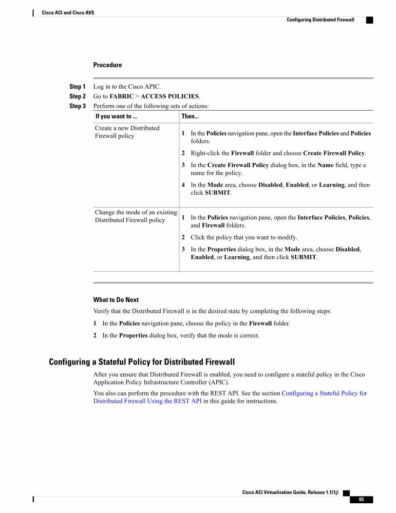
Procedure
Step 1 Log in to the Cisco APIC.Step 2 Go to FABRIC > ACCESS POLICIES.Step 3 Perform one of the following sets of actions:
Then...If you want to ...
1 In thePolicies navigation pane, open the Interface Policies andPoliciesfolders.
2 Right-click the Firewall folder and choose Create Firewall Policy.
3 In the Create Firewall Policy dialog box, in the Name field, type aname for the policy.
4 In theMode area, choose Disabled, Enabled, or Learning, and thenclick SUBMIT.
Create a new DistributedFirewall policy
1 In the Policies navigation pane, open the Interface Policies, Policies,and Firewall folders.
2 Click the policy that you want to modify.
3 In the Properties dialog box, in theMode area, choose Disabled,Enabled, or Learning, and then click SUBMIT.
Change the mode of an existingDistributed Firewall policy
What to Do Next
Verify that the Distributed Firewall is in the desired state by completing the following steps:
1 In the Policies navigation pane, choose the policy in the Firewall folder.
2 In the Properties dialog box, verify that the mode is correct.
Configuring a Stateful Policy for Distributed FirewallAfter you ensure that Distributed Firewall is enabled, you need to configure a stateful policy in the CiscoApplication Policy Infrastructure Controller (APIC).
You also can perform the procedure with the REST API. See the section Configuring a Stateful Policy forDistributed Firewall Using the REST API in this guide for instructions.
Cisco ACI Virtualization Guide, Release 1.1(1j) 65
Cisco ACI and Cisco AVSConfiguring Distributed Firewall

Procedure
Step 1 In the Cisco APIC, choose TENANTS.Step 2 In the navigation pane, expand the folder for the tenant for which you want to configure the policy and then
expand the Security Policies folder.Step 3 Right-click the Contracts folder and then choose Create Contract.Step 4 In the Create Contract dialog box, in the Name field, type a name for the contract.Step 5 In the Subjects area, click the + icon.Step 6 In the Create Contract Subject dialog box, in the Name field, type a name for the subject.Step 7 In the Filters area, click the + icon next to FILTERS.Step 8 Click the down arrow to display the Name drop-down filter list, and then click the + icon at the top of the
Name list.Step 9 In the Create Filter dialog box, complete the following actions:
a) In the Name field, type a name for the filter.b) In the Entries area, click the + icon to display additional fields below.c) In the Name field, type a name to further describe the filter, if necessary.d) From the Ether Type drop-down menu, choose IP.e) From the IP Protocol field, choose tcp.f) Check the Stateful check box.g) (Optional) In the Source Port / Range field, from the To and the From drop-down menus, choose
Unspecified, the default.h) In the Destination Port / Range field, from the To and the From drop-down menus, choose http.i) Click UPDATE and then click SUBMIT.
Step 10 In the Create Contract Subject dialog box, in the Filters area, click UPDATE and then click OK.Step 11 In the Create Contract dialog box, click SUBMIT.
Enabling Distributed Firewall After Installation or UpgradeWhen you install or upgrade to Cisco Application Virtual Switch (AVS) Release 5.2(1)SV3(1.5), DistributedFirewall is in learning mode by default. After you install or upgrade to Release 5.2(1)SV3(1.5), you must putDistributed Firewall into enabled mode if you want to use the feature.
Distributed Firewall is in learning mode by default in Release 5.2(1)SV3(1.5) to facilitate upgrades fromprevious versions of Cisco AVS. Learning mode allows the flow of traffic on the Cisco AVS and createsconnections in the established state.
If Distributed Firewall is enabled before the upgrade, post-upgrade traffic will be affected. After the upgrade,Distributed Firewall will drop all the packets—for connections that were running before the upgrade—becauseit does not have any active connections created.
See the section Distributed Firewall in this guide for more information.
Use the following procedure to enable Distributed Firewall after you install or upgrade to Cisco AVS Release5.2(1)SV3(1.5)
Cisco ACI Virtualization Guide, Release 1.1(1j)66
Cisco ACI and Cisco AVSConfiguring Distributed Firewall
Procedure
Step 1 Log into the Cisco APIC.Step 2 Go to FABRIC > ACCESS POLICIES.Step 3 In the left navigation pane, open the Interface Policies, Policies, and Firewall folders.Step 4 Click the policy that you want to modify.Step 5 In the Properties dialog box in the work pane, in theMode area, choose the Enabled radio button.
Microsegmentation with Cisco AVSMicrosegmentation with the Cisco Application Virtual Switch (AVS) provides the ability to automaticallyassign endpoints to logical security zones called endpoint groups (EPGs) based on various attributes.Microsegmentation with Cisco AVS is a new feature in Cisco AVS Release 5.2(1)SV3(1.5).
This feature is available in the Cisco Application Centric Infrastructure (ACI) for Cisco AVS only; it is notavailable with VMware DVS.
Microsegmentation polices used by the Cisco AVS are centrally managed by the Cisco Application PolicyInfrastructure Controller (APIC) and enforced by the fabric. This section assumes that you are familiar withEPGs, tenants, contracts, and other key concepts regarding ACI policies. For more information, see CiscoApplication Centric Infrastructure Fundamentals.
Benefits of Microsegmentation with Cisco AVSEndpoint groups (EPGs) are used to group virtual machines (VMs) within a tenant and apply filtering andforwarding policies to them.Microsegmentation with Cisco Application Virtual Switch (AVS) adds the abilityto associate EPGs with network or VM-based attributes, enabling you to filter with those attributes and applymore dynamic policies.Microsegmentationwith Cisco AVS also allows you to apply policies to any endpointswithin the tenant.
Example: Microsegmentation with Cisco AVS Within a Single EPG or Multiple EPGs in the Same Tenant
You might assign web servers to an EPG so that you can apply the similar policies. By default, all endpointswithin an EPG can freely communicate with each other. However, if this web EPG contains a mix of productionand development web servers, you might not want to allow communication between these different types ofweb servers. Microsegmentation with Cisco AVS allows you to create a new EPG and autoassign endpointsbased on their VM name attribute, such as "Prod-xxxx" or "Dev-xxx".
Example: Microsegmentation for Endpoint Quarantine
You might have separate EPGs for web servers and database servers, and each one contains both Windowsand Linux VMs. If a virus affecting only Windows threatens your network, you can isolate Windows VMsacross all EPGs by creating a newEPG called, for example, "Windows-Quarantine" and applying the VM-basedoperating systems attribute to filter out all Windows-based endpoints. This quarantined EPG could have morerestrictive communication policies, such as limiting allowed protocols or preventing communication to anyother EPGs.
Cisco ACI Virtualization Guide, Release 1.1(1j) 67
Cisco ACI and Cisco AVSMicrosegmentation with Cisco AVS
How Microsegmentation Using Cisco AVS WorksMicrosegmentation using Cisco Application Virtual Switch (AVS) involves the Cisco Application PolicyInfrastructure Controller (APIC), vCenter and leaf switches. This section describes the workflow forMicrosegmentation using the Cisco AVS.
Cisco APIC
1 The user configures the Cisco AVS in the Cisco APIC.2 The Cisco APIC connects to vCenter and does the following:
a Creates an instance of the Cisco AVS.
b Pulls virtual machine (VM) and hypervisor inventory and information about the VM attributes as soonas the Cisco AVS hypervisor is attached to the Cisco AVS-distributed virtual switch (DVS) instancein vCenter.
c Starts a listener for new events from vCenter.
3 The user creates a base endpoint group (EPG) and associates it with a Cisco AVS vCenter domain. In eachvCenter domain, a new encapsulation is allocated for this base EPG. The base EPG does not have anyattributes.
The vCenter administrator assigns virtual endpoints to this base EPG—not to any attribute-based EPGs.It is the base EPG that appears in vCenter as a port group.
Note
4 The user creates an attribute-based EPG
The attribute-based EPG does not appear in vCenter as a port group; it has a special function: Theattribute-based EPG has VM-based attributes to match filter criteria. If a match occurs between theattribute-based EPG VM attributes and VMs, the Cisco APIC dynamically assigns the VMs to theattribute-based EPG.
The endpoints are transferred from the base EPG to the attribute-based EPG. If the attribute-based EPGis deleted, the endpoints are assigned back to the base EPG.
The attribute-based EPG must be assigned to a virtual machine manager (VMM) domain in order for it totake effect on the Cisco AVS. When you associate an attribute-based EPG to a VMM domain, its criteriawill be applied for that VMM domain only.
Leaf Switch and Cisco AVS
1 The physical leaf switch pulls the attribute policies from the Cisco APIC.
2 The Cisco AVS sends a VM attach message to the physical leaf switch using the OpFlex protocol whena VM attaches to the Cisco AVS.
3 The physical leaf switch matches the VM against the configured attribute policies for the tenant.
4 If the VM matches the configured VM attributes, the physical leaf switch pushes the attribute-basedEPG—along with the corresponding encapsulation— to the Cisco AVS.
Note that this action does not change the original port-group assignment for the VM in vCenter.
Cisco ACI Virtualization Guide, Release 1.1(1j)68
Cisco ACI and Cisco AVSHow Microsegmentation Using Cisco AVS Works
Packet Forwarding
1 When the VM sends data packets, the Cisco AVS tags the packets with the attribute-based EPG andcorresponding encapsulation (VLAN/VXLAN) information.
This is the same information that the Cisco AVS received that was derived from the attribute-based EPGinstead of the base EPG assigned to the port group.
2 The physical leaf hardware sees an attribute-based encapsulated VM packet and matches it with theconfigured policy.
The VM is dynamically assigned to an attribute-based EPG, and the packet is forwarded based on thepolicy defined for that particular attribute-based EPG.
Attributes for Microsegmentation with Cisco AVSApplying attributes to endpoint groups (EPGs) enables you to apply forwarding and security policies withgreater granularity than you can to EPGs without attributes. Attributes are unique within the tenant.
There are two types of attributes that you can apply to EPGs: network-based attributes and virtual machine(VM)-based attributes. You apply the attributes in Cisco Application Policy Infrastructure Controller (APIC)when you configure the EPG.
The APIC GUI, when you configure an attribute-based EPG, initially uses the term VM attributes to referto all attributes—network-based and VM-based. However, when you choose the option for creatingattributes, the GUI then specifies the type of attribute.
Note
Network-Based Attributes
The network-based attributes areMACAddress Filter and IP Address Filter. You can apply one or moreMACor IP addresses to an EPG.
For IP addresses, you simply specify the address or the subnet; for MAC addresses, you simply specify theaddress. You do not specify an operator or any other information relating to the attribute.
VM-Based Attributes
You can applymultiple VM-based attributes to an EPG. The VM-based attributes are VMMDomain, OperatingSystem, Hypervisor Identifier, Datacenter, VM Identifier, VM Name, VNic Dn, and Custom Attribute.
Custom Attribute allows you to define an attribute based on criteria not used in other attributes. For example,you might want to define a CustomAttribute called "Security Zone" in vCenter and then associate this attributeto one or more VMs with such values as "DMZ" or "Edge." The APIC administrator can then create anattribute-based EPG based on that VM custom attribute.
Cisco ACI Virtualization Guide, Release 1.1(1j) 69
Cisco ACI and Cisco AVSAttributes for Microsegmentation with Cisco AVS
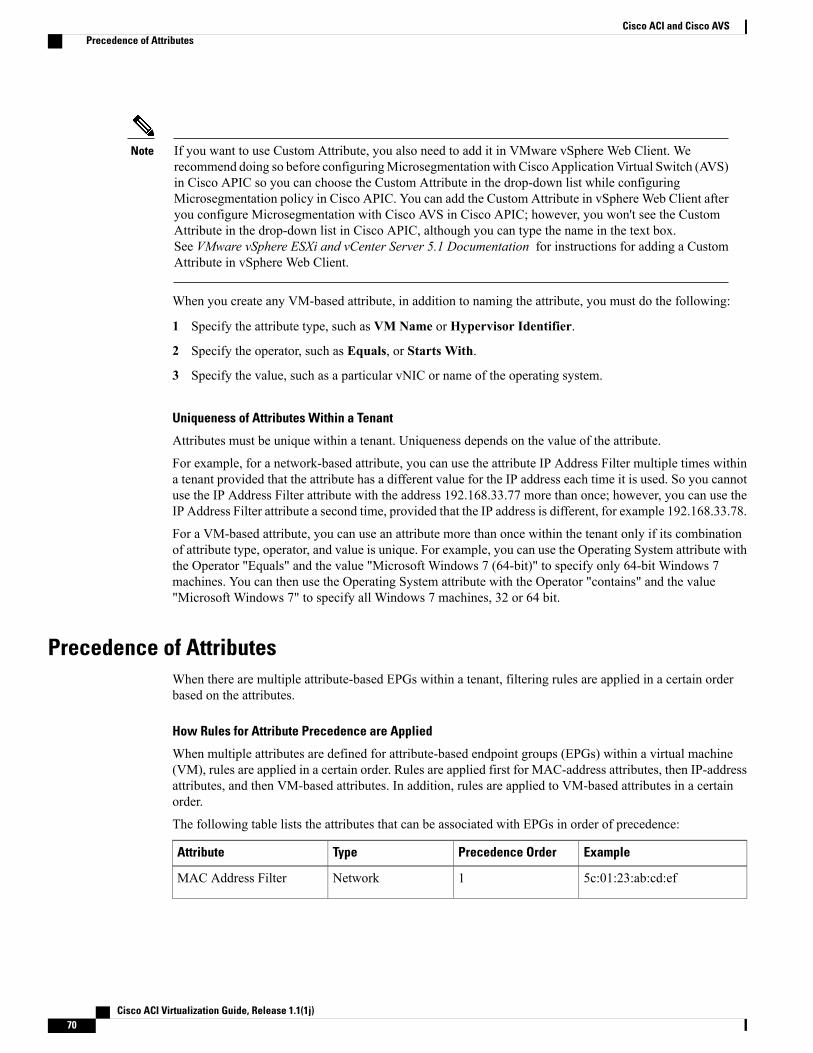
If you want to use Custom Attribute, you also need to add it in VMware vSphere Web Client. Werecommend doing so before configuringMicrosegmentationwith Cisco ApplicationVirtual Switch (AVS)in Cisco APIC so you can choose the Custom Attribute in the drop-down list while configuringMicrosegmentation policy in Cisco APIC. You can add the Custom Attribute in vSphere Web Client afteryou configure Microsegmentation with Cisco AVS in Cisco APIC; however, you won't see the CustomAttribute in the drop-down list in Cisco APIC, although you can type the name in the text box.See VMware vSphere ESXi and vCenter Server 5.1 Documentation for instructions for adding a CustomAttribute in vSphere Web Client.
Note
When you create any VM-based attribute, in addition to naming the attribute, you must do the following:
1 Specify the attribute type, such as VM Name or Hypervisor Identifier.
2 Specify the operator, such as Equals, or Starts With.
3 Specify the value, such as a particular vNIC or name of the operating system.
Uniqueness of Attributes Within a Tenant
Attributes must be unique within a tenant. Uniqueness depends on the value of the attribute.
For example, for a network-based attribute, you can use the attribute IP Address Filter multiple times withina tenant provided that the attribute has a different value for the IP address each time it is used. So you cannotuse the IP Address Filter attribute with the address 192.168.33.77 more than once; however, you can use theIP Address Filter attribute a second time, provided that the IP address is different, for example 192.168.33.78.
For a VM-based attribute, you can use an attribute more than once within the tenant only if its combinationof attribute type, operator, and value is unique. For example, you can use the Operating System attribute withthe Operator "Equals" and the value "Microsoft Windows 7 (64-bit)" to specify only 64-bit Windows 7machines. You can then use the Operating System attribute with the Operator "contains" and the value"Microsoft Windows 7" to specify all Windows 7 machines, 32 or 64 bit.
Precedence of AttributesWhen there are multiple attribute-based EPGs within a tenant, filtering rules are applied in a certain orderbased on the attributes.
How Rules for Attribute Precedence are Applied
When multiple attributes are defined for attribute-based endpoint groups (EPGs) within a virtual machine(VM), rules are applied in a certain order. Rules are applied first for MAC-address attributes, then IP-addressattributes, and then VM-based attributes. In addition, rules are applied to VM-based attributes in a certainorder.
The following table lists the attributes that can be associated with EPGs in order of precedence:
ExamplePrecedence OrderTypeAttribute
5c:01:23:ab:cd:ef1NetworkMAC Address Filter
Cisco ACI Virtualization Guide, Release 1.1(1j)70
Cisco ACI and Cisco AVSPrecedence of Attributes
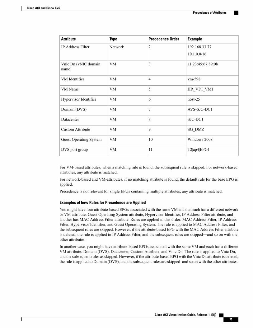
ExamplePrecedence OrderTypeAttribute
192.168.33.77
10.1.0.0/16
2NetworkIP Address Filter
a1:23:45:67:89:0b3VMVnic Dn (vNIC domainname)
vm-5984VMVM Identifier
HR_VDI_VM15VMVM Name
host-256VMHypervisor Identifier
AVS-SJC-DC17VMDomain (DVS)
SJC-DC18VMDatacenter
SG_DMZ9VMCustom Attribute
Windows 200810VMGuest Operating System
T2|ap4|EPG111VMDVS port group
For VM-based attributes, when a matching rule is found, the subsequent rule is skipped. For network-basedattributes, any attribute is matched.
For network-based and VM-attributes, if no matching attribute is found, the default rule for the base EPG isapplied.
Precedence is not relevant for single EPGs containing multiple attributes; any attribute is matched.
Examples of how Rules for Precedence are Applied
You might have four attribute-based EPGs associated with the same VM and that each has a different networkor VM attribute: Guest Operating System attribute, Hypervisor Identifier, IP Address Filter attribute, andanother has MAC Address Filter attribute. Rules are applied in this order: MAC Address Filter, IP AddressFilter, Hypervisor Identifier, and Guest Operating System. The rule is applied to MAC Address Filter, andthe subsequent rules are skipped. However, if the attribute-based EPG with the MAC Address Filter attributeis deleted, the rule is applied to IP Address Filter, and the subsequent rules are skipped—and so on with theother attributes.
In another case, you might have attribute-based EPGs associated with the same VM and each has a differentVM attribute: Domain (DVS), Datacenter, Custom Attribute, and Vnic Dn. The rule is applied to Vnic Dn,and the subsequent rules as skipped. However, if the attribute-based EPGwith the Vnic Dn attribute is deleted,the rule is applied to Domain (DVS), and the subsequent rules are skipped–and so on with the other attributes.
Cisco ACI Virtualization Guide, Release 1.1(1j) 71
Cisco ACI and Cisco AVSPrecedence of Attributes
Configuring Microsegmentation with Cisco AVSThe following sections contain instructions for configuringMicrosegmentation with Cisco Application VirtualSwitch (AVS) using the Cisco Application Policy Infrastructure Controller (APIC) GUI for two different usecases. You can adapt the procedures for your network's specific needs.
If VXLAN load balancing is enabled in the VMware vCenter domain profile, Microsegmentation withCisco AVS cannot be enabled on the domain.
Note
Before You Begin
• You need to create a base endpoint group (EPG) for the virtual machine (VM) before you can create adynamic EPG with one or more attributes.
• You need to create a contract before creating a dynamic EPG with one or more attributes if you want toassociate the EPG with a contract.
Workflow for Configuring Microsegmentation with Cisco AVSThis section provides a high-level description of the tasks that you need to perform in order to configureMicrosegmentation with Cisco AVS.
1 Gather information through the CLI about the endpoints that you want to put into a new attribute-basedendpoint group (EPG).
2 In Cisco APIC, specify a name and bridge domain for the new attribute-based EPG, associate it with avirtual machine (VM) domain profile, and then choose the EPG's resolution immediacy.
3 Choose a network-based or VM-based attribute for the EPG.
4 Verify that the attribute-based EPG was created correctly.
Follow the instructions for these steps in the sections Configuring Microsegmentation with Cisco AVS toIsolate VMs Within an EPG and Configuring Microsegmentation with Cisco AVS in Different Base EPGs.
Configuring Microsegmentation with Cisco AVS to Isolate VMs Within an EPGYou can use Microsegmentation with Cisco Application Virtual Switch (AVS) to create a new, attribute-basedendpoint group (EPG) to contain virtual machines (VMs) from a single base EPG. By default, VMs within abase EPG can communicate with each other; however, you might want to prevent communication betweensome VMs within the EPG. This section provides an example of such a circumstance and the steps you needto take to configure Microsegmentation with Cisco AVS.
Example: Isolating VMs from the Same Base EPGYour company deploys a virtual desktop infrastructure (VDI) for its Human Resources, Finance, and Operationsdepartments. The VDI virtual desktop VMs are part of a single base EPG called EPG_VDI with identicalaccess requirements to the rest of the base EPGs.
Cisco ACI Virtualization Guide, Release 1.1(1j)72
Cisco ACI and Cisco AVSConfiguring Microsegmentation with Cisco AVS
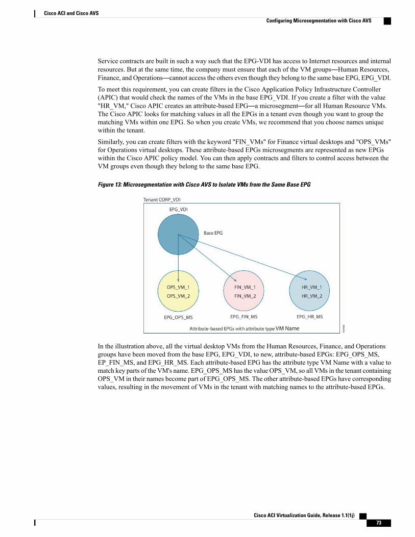
Service contracts are built in such a way such that the EPG-VDI has access to Internet resources and internalresources. But at the same time, the company must ensure that each of the VM groups—Human Resources,Finance, and Operations—cannot access the others even though they belong to the same base EPG, EPG_VDI.
To meet this requirement, you can create filters in the Cisco Application Policy Infrastructure Controller(APIC) that would check the names of the VMs in the base EPG_VDI. If you create a filter with the value"HR_VM," Cisco APIC creates an attribute-based EPG—a microsegment—for all Human Resource VMs.The Cisco APIC looks for matching values in all the EPGs in a tenant even though you want to group thematching VMs within one EPG. So when you create VMs, we recommend that you choose names uniquewithin the tenant.
Similarly, you can create filters with the keyword "FIN_VMs" for Finance virtual desktops and "OPS_VMs"for Operations virtual desktops. These attribute-based EPGs microsegments are represented as new EPGswithin the Cisco APIC policy model. You can then apply contracts and filters to control access between theVM groups even though they belong to the same base EPG.
Figure 13: Microsegmentation with Cisco AVS to Isolate VMs from the Same Base EPG
In the illustration above, all the virtual desktop VMs from the Human Resources, Finance, and Operationsgroups have been moved from the base EPG, EPG_VDI, to new, attribute-based EPGs: EPG_OPS_MS,EP_FIN_MS, and EPG_HR_MS. Each attribute-based EPG has the attribute type VM Name with a value tomatch key parts of the VM's name. EPG_OPS_MS has the value OPS_VM, so all VMs in the tenant containingOPS_VM in their names become part of EPG_OPS_MS. The other attribute-based EPGs have correspondingvalues, resulting in the movement of VMs in the tenant with matching names to the attribute-based EPGs.
Cisco ACI Virtualization Guide, Release 1.1(1j) 73
Cisco ACI and Cisco AVSConfiguring Microsegmentation with Cisco AVS
The following steps:Note
• Assume that you already have VMs with names that can be used with the filters that you will usewhen creating the attribute-based EPGs. However, if you do not have VMs with names that can beused, you can go ahead and create the attribute-based EPGs and then change the VM names that canbe used with the filters. The Cisco APIC will automatically make the VMs part of the newattribute-based EPGs.
• Assume that if you follow the steps for your own case, you will already have a base EPG.
• Use an attribute, names, and other values based on the preceding example; you need to choose yourown attributes, names, and values.
You cannot add VM attributes to an existing base EPG if endpoints have been assigned to it. You canexplicitly delete the EPG-to-domain association and then configure attributes. You can add attributes toan existing attribute-based EPG even if it associated with a domain.
Important
Procedure
Step 1 Log in to the Cisco APIC.Step 2 Choose TENANTS and then choose the tenant within which you want to create a microsegment.Step 3 In the tenant navigation pane, expand the tenant folder, theApplication Profiles folder, and the profile folder,
and then click the Application EPGs folder.Step 4 In the work pane, click the table view icon to display the EPGs for the tenant.Step 5 In the work pane, double-click the EPG EPG_VDI.
The EPG EPG_VDI folder opens in the tenant navigation pane, and properties for EPG_VDI appear in thework pane.
Step 6 In the work pane, click the OPERATIONAL tab at the right top of the screen.The work pane displays all the VMs that belong to EPG_VDI.
Step 7 Note the VLAN or VXLAN encapsulation ID for the VMs that you want to put into an attribute-based EPG.Step 8 In the Cisco APIC tenant navigation pane, right-click the Application EPGs folder and then choose Create
Application EPG.Step 9 Complete the following steps to create an attribute-based EPG for one of the groups of VMs:
a) In the Create Application EPG STEP 1> IDENTITY dialog box, in the Name field, enter a name.We recommend that you choose a name that indicates that the new attribute-based EPG is a microsegment.For example, in the case described in this section, you might want to use the name HR_VM_MS for theattribute-based EPG, or microsegment, for Human Resource VMs.
b) In the Bridge Domain area, choose a bridge domain from the drop-down list.c) Check the Associate to VM Domain Profiles check box.d) Click NEXT.e) In the Create Application EPG STEP 2 > DOMAINS dialog box, in the Associated VM Domain
Profiles area, click the + icon to display the list of domain profiles, and then choose a domain profile.f) In the Resolution Immediacy area, choose Immediate from the drop-down list.
Cisco ACI Virtualization Guide, Release 1.1(1j)74
Cisco ACI and Cisco AVSConfiguring Microsegmentation with Cisco AVS
By default, resolution immediacy is On Demand. However, you must set resolution immediacyto Immediate for any attribute-based EPG.
Note
g) Click UPDATE.h) In the Associated VM Attributes area, choose VM Attributes Filter from the drop-down list.i) In the Create VM Attribute dialog box, in the Name field, enter a name.
We recommend that you choose a name that reflects the filter's function. For example, in the case describedin this section, you might want to use the name hrvmcontains for the filter for the Human Resource EPG.
j) In the Type area, choose VM Name from the drop-down list.k) In the Operator area, choose Contains from the drop-down list.l) In the Value area, enter a value for VM Name.
For example, in the case described in this section, you might want to enter HR_VM.
m) Click OK.n) In the Create Application EPG STEP 2 > DOMAINS dialog box, click FINISH.
Step 10 Repeat Step 9 and Step 10 for the other attribute-based EPGs that you want to create with VMs within thesame base EPG.
What to Do Next
Verify that the attribute-based EPG was created correctly.
1 In the Cisco APIC navigation pane, click the Application EPGs folder to display the list of EPGs andclick the new attribute-based EPG.
2 In the work plane, click theOPERATIONAL tab and verify that the VMs that you wanted to move fromthe base EPG appear as endpoints for the new attribute-based EPG. Also verify that they have a VLANpool different from the one that you noted in Step 7.
3 In the navigation pane, click the base EPG of the VMs that you moved to the new, attribute-based EPG.
4 In the work plane, click the OPERATIONAL tab and verify that the VMs that you moved to the new,attribute-based EPG no longer appear as endpoints for the base EPG.
Configuring Microsegmentation with Cisco AVS in Different Base EPGsYou can configure Microsegmentation with Cisco Application Virtual Switch (AVS) to put virtual machines(VMs) that belong to different base endpoint groups (EPGs) into a new attribute-based EPG. You might wantto do this to apply policy to VMs that share a certain characteristic although they belong to different baseEPGs. This section provides and example of such a circumstance and the steps you need to take to configureMicrosegmentation with Cisco AVS.
Example: Putting VMs in Different Base EPGs into a New Attribute-Based EPGYour company deploys a three-tier web application. The application is built on virtual machines (VMs) thatrun different operating systems and different versions of the same operating system. For example, the VMsmight run Linux, Windows 2008, and Windows 2008 R2. The application is distributed; the company hasdivided the VMs into three different EPGs: EPG_Web, EPG_App, and EPG_DB.
Because of a recent vulnerability in the Windows 2008 operating system, your company's security teamdecided to quarantine VMs running Windows 2008 in case those VMs are compromised. The security teamalso decided to upgrade allWindows 2008 VMs toWindows 2012. It also wants to microsegment all productionVMs across all EPGs and restrict external connectivity to those VMs.
Cisco ACI Virtualization Guide, Release 1.1(1j) 75
Cisco ACI and Cisco AVSConfiguring Microsegmentation with Cisco AVS
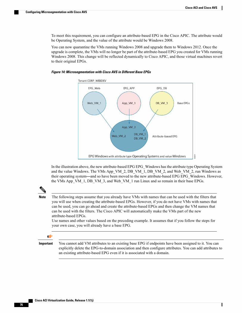
To meet this requirement, you can configure an attribute-based EPG in the Cisco APIC. The attribute wouldbe Operating System, and the value of the attribute would be Windows 2008.
You can now quarantine the VMs running Windows 2008 and upgrade them to Windows 2012. Once theupgrade is complete, the VMs will no longer be part of the attribute-based EPG you created for VMs runningWindows 2008. This change will be reflected dynamically to Cisco APIC, and those virtual machines revertto their original EPGs.
Figure 14: Microsegmentation with Cisco AVS in Different Base EPGs
In the illustration above, the new attribute-based EPG EPG_Windows has the attribute type Operating Systemand the value Windows. The VMs App_VM_2, DB_VM_1, DB_VM_2, and Web_VM_2, run Windows astheir operating system—and so have been moved to the new attribute-based EPG EPG_Windows. However,the VMs App_VM_1, DB_VM_3, and Web_VM_1 run Linux and so remain in their base EPGs.
The following steps assume that you already have VMs with names that can be used with the filters thatyou will use when creating the attribute-based EPGs. However, if you do not have VMs with names thatcan be used, you can go ahead and create the attribute-based EPGs and then change the VM names thatcan be used with the filters. The Cisco APIC will automatically make the VMs part of the newattribute-based EPGs.Use names and other values based on the preceding example. It assumes that if you follow the steps foryour own case, you will already have a base EPG.
Note
You cannot add VM attributes to an existing base EPG if endpoints have been assigned to it. You canexplicitly delete the EPG-to-domain association and then configure attributes. You can add attributes toan existing attribute-based EPG even if it is associated with a domain.
Important
Cisco ACI Virtualization Guide, Release 1.1(1j)76
Cisco ACI and Cisco AVSConfiguring Microsegmentation with Cisco AVS
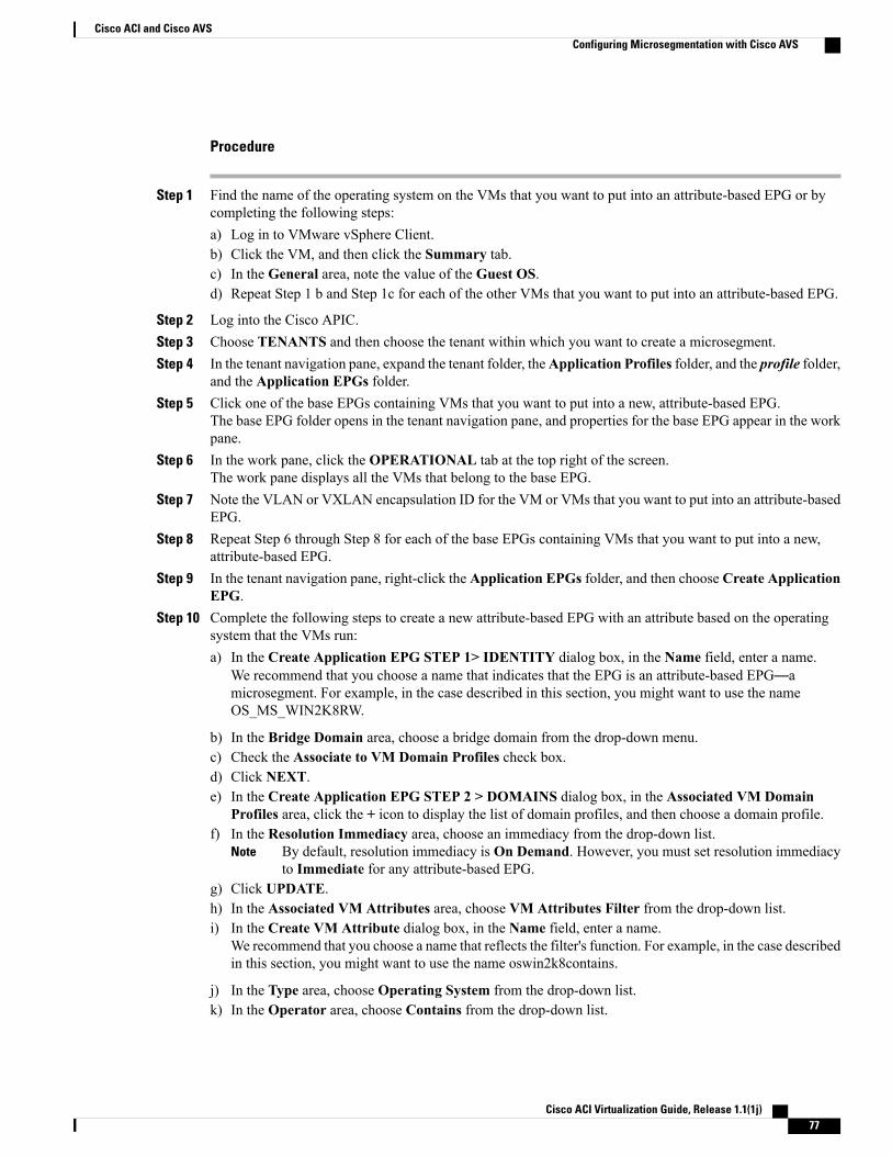
Procedure
Step 1 Find the name of the operating system on the VMs that you want to put into an attribute-based EPG or bycompleting the following steps:a) Log in to VMware vSphere Client.b) Click the VM, and then click the Summary tab.c) In the General area, note the value of the Guest OS.d) Repeat Step 1 b and Step 1c for each of the other VMs that you want to put into an attribute-based EPG.
Step 2 Log into the Cisco APIC.Step 3 Choose TENANTS and then choose the tenant within which you want to create a microsegment.Step 4 In the tenant navigation pane, expand the tenant folder, theApplication Profiles folder, and the profile folder,
and the Application EPGs folder.Step 5 Click one of the base EPGs containing VMs that you want to put into a new, attribute-based EPG.
The base EPG folder opens in the tenant navigation pane, and properties for the base EPG appear in the workpane.
Step 6 In the work pane, click the OPERATIONAL tab at the top right of the screen.The work pane displays all the VMs that belong to the base EPG.
Step 7 Note the VLAN or VXLAN encapsulation ID for the VM or VMs that you want to put into an attribute-basedEPG.
Step 8 Repeat Step 6 through Step 8 for each of the base EPGs containing VMs that you want to put into a new,attribute-based EPG.
Step 9 In the tenant navigation pane, right-click the Application EPGs folder, and then choose Create ApplicationEPG.
Step 10 Complete the following steps to create a new attribute-based EPG with an attribute based on the operatingsystem that the VMs run:a) In the Create Application EPG STEP 1> IDENTITY dialog box, in the Name field, enter a name.
We recommend that you choose a name that indicates that the EPG is an attribute-based EPG—amicrosegment. For example, in the case described in this section, you might want to use the nameOS_MS_WIN2K8RW.
b) In the Bridge Domain area, choose a bridge domain from the drop-down menu.c) Check the Associate to VM Domain Profiles check box.d) Click NEXT.e) In the Create Application EPG STEP 2 > DOMAINS dialog box, in the Associated VM Domain
Profiles area, click the + icon to display the list of domain profiles, and then choose a domain profile.f) In the Resolution Immediacy area, choose an immediacy from the drop-down list.
By default, resolution immediacy is On Demand. However, you must set resolution immediacyto Immediate for any attribute-based EPG.
Note
g) Click UPDATE.h) In the Associated VM Attributes area, choose VM Attributes Filter from the drop-down list.i) In the Create VM Attribute dialog box, in the Name field, enter a name.
We recommend that you choose a name that reflects the filter's function. For example, in the case describedin this section, you might want to use the name oswin2k8contains.
j) In the Type area, choose Operating System from the drop-down list.k) In the Operator area, choose Contains from the drop-down list.
Cisco ACI Virtualization Guide, Release 1.1(1j) 77
Cisco ACI and Cisco AVSConfiguring Microsegmentation with Cisco AVS
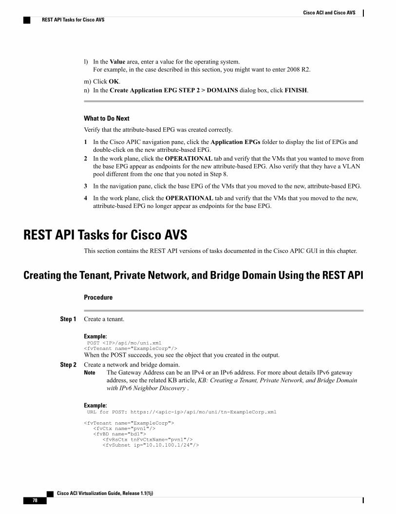
l) In the Value area, enter a value for the operating system.For example, in the case described in this section, you might want to enter 2008 R2.
m) Click OK.n) In the Create Application EPG STEP 2 > DOMAINS dialog box, click FINISH.
What to Do Next
Verify that the attribute-based EPG was created correctly.
1 In the Cisco APIC navigation pane, click the Application EPGs folder to display the list of EPGs anddouble-click on the new attribute-based EPG.
2 In the work plane, click theOPERATIONAL tab and verify that the VMs that you wanted to move fromthe base EPG appear as endpoints for the new attribute-based EPG. Also verify that they have a VLANpool different from the one that you noted in Step 8.
3 In the navigation pane, click the base EPG of the VMs that you moved to the new, attribute-based EPG.
4 In the work plane, click the OPERATIONAL tab and verify that the VMs that you moved to the new,attribute-based EPG no longer appear as endpoints for the base EPG.
REST API Tasks for Cisco AVSThis section contains the REST API versions of tasks documented in the Cisco APIC GUI in this chapter.
Creating the Tenant, Private Network, and Bridge Domain Using the REST API
Procedure
Step 1 Create a tenant.
Example:POST <IP>/api/mo/uni.xml<fvTenant name="ExampleCorp"/>When the POST succeeds, you see the object that you created in the output.
Step 2 Create a network and bridge domain.The Gateway Address can be an IPv4 or an IPv6 address. For more about details IPv6 gatewayaddress, see the related KB article, KB: Creating a Tenant, Private Network, and Bridge Domainwith IPv6 Neighbor Discovery .
Note
Example:URL for POST: https://<apic-ip>/api/mo/uni/tn-ExampleCorp.xml
<fvTenant name="ExampleCorp"><fvCtx name="pvn1"/><fvBD name="bd1">
<fvRsCtx tnFvCtxName="pvn1"/><fvSubnet ip="10.10.100.1/24"/>
Cisco ACI Virtualization Guide, Release 1.1(1j)78
Cisco ACI and Cisco AVSREST API Tasks for Cisco AVS
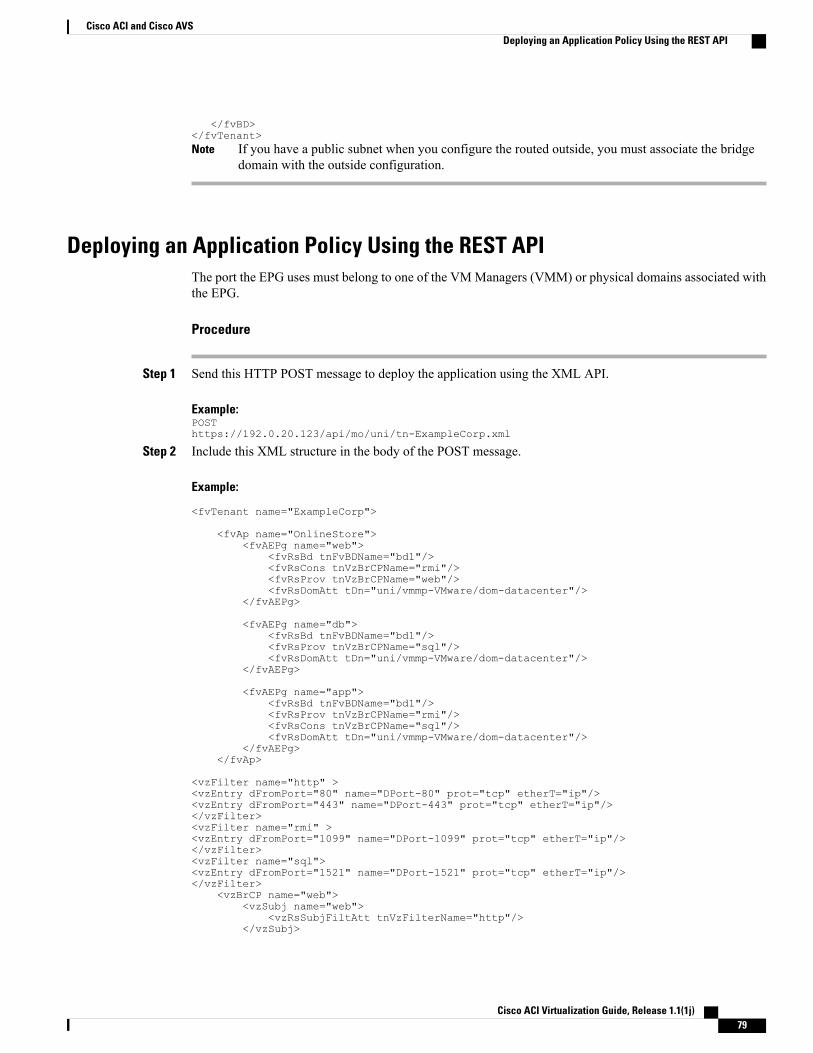
</fvBD></fvTenant>
If you have a public subnet when you configure the routed outside, you must associate the bridgedomain with the outside configuration.
Note
Deploying an Application Policy Using the REST APIThe port the EPG uses must belong to one of the VMManagers (VMM) or physical domains associated withthe EPG.
Procedure
Step 1 Send this HTTP POST message to deploy the application using the XML API.
Example:POSThttps://192.0.20.123/api/mo/uni/tn-ExampleCorp.xml
Step 2 Include this XML structure in the body of the POST message.
Example:
<fvTenant name="ExampleCorp">
<fvAp name="OnlineStore"><fvAEPg name="web">
<fvRsBd tnFvBDName="bd1"/><fvRsCons tnVzBrCPName="rmi"/><fvRsProv tnVzBrCPName="web"/><fvRsDomAtt tDn="uni/vmmp-VMware/dom-datacenter"/>
</fvAEPg>
<fvAEPg name="db"><fvRsBd tnFvBDName="bd1"/><fvRsProv tnVzBrCPName="sql"/><fvRsDomAtt tDn="uni/vmmp-VMware/dom-datacenter"/>
</fvAEPg>
<fvAEPg name="app"><fvRsBd tnFvBDName="bd1"/><fvRsProv tnVzBrCPName="rmi"/><fvRsCons tnVzBrCPName="sql"/><fvRsDomAtt tDn="uni/vmmp-VMware/dom-datacenter"/>
</fvAEPg></fvAp>
<vzFilter name="http" ><vzEntry dFromPort="80" name="DPort-80" prot="tcp" etherT="ip"/><vzEntry dFromPort="443" name="DPort-443" prot="tcp" etherT="ip"/></vzFilter><vzFilter name="rmi" ><vzEntry dFromPort="1099" name="DPort-1099" prot="tcp" etherT="ip"/></vzFilter><vzFilter name="sql"><vzEntry dFromPort="1521" name="DPort-1521" prot="tcp" etherT="ip"/></vzFilter>
<vzBrCP name="web"><vzSubj name="web">
<vzRsSubjFiltAtt tnVzFilterName="http"/></vzSubj>
Cisco ACI Virtualization Guide, Release 1.1(1j) 79
Cisco ACI and Cisco AVSDeploying an Application Policy Using the REST API
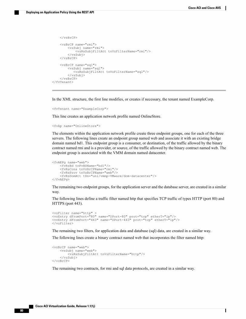
</vzBrCP>
<vzBrCP name="rmi"><vzSubj name="rmi">
<vzRsSubjFiltAtt tnVzFilterName="rmi"/></vzSubj>
</vzBrCP>
<vzBrCP name="sql"><vzSubj name="sql">
<vzRsSubjFiltAtt tnVzFilterName="sql"/></vzSubj>
</vzBrCP></fvTenant>
In the XML structure, the first line modifies, or creates if necessary, the tenant named ExampleCorp.
<fvTenant name="ExampleCorp">
This line creates an application network profile named OnlineStore.
<fvAp name="OnlineStore">
The elements within the application network profile create three endpoint groups, one for each of the threeservers. The following lines create an endpoint group named web and associate it with an existing bridgedomain named bd1. This endpoint group is a consumer, or destination, of the traffic allowed by the binarycontract named rmi and is a provider, or source, of the traffic allowed by the binary contract named web. Theendpoint group is associated with the VMM domain named datacenter.
<fvAEPg name="web"><fvRsBd tnFvBDName="bd1"/><fvRsCons tnVzBrCPName="rmi"/><fvRsProv tnVzBrCPName="web"/><fvRsDomAtt tDn="uni/vmmp-VMware/dom-datacenter"/>
</fvAEPg>
The remaining two endpoint groups, for the application server and the database server, are created in a similarway.
The following lines define a traffic filter named http that specifies TCP traffic of types HTTP (port 80) andHTTPS (port 443).
<vzFilter name="http" ><vzEntry dFromPort="80" name="DPort-80" prot="tcp" etherT="ip"/><vzEntry dFromPort="443" name="DPort-443" prot="tcp" etherT="ip"/></vzFilter>
The remaining two filters, for application data and database (sql) data, are created in a similar way.
The following lines create a binary contract named web that incorporates the filter named http:
<vzBrCP name="web"><vzSubj name="web">
<vzRsSubjFiltAtt tnVzFilterName="http"/></vzSubj>
</vzBrCP>
The remaining two contracts, for rmi and sql data protocols, are created in a similar way.
Cisco ACI Virtualization Guide, Release 1.1(1j)80
Cisco ACI and Cisco AVSDeploying an Application Policy Using the REST API
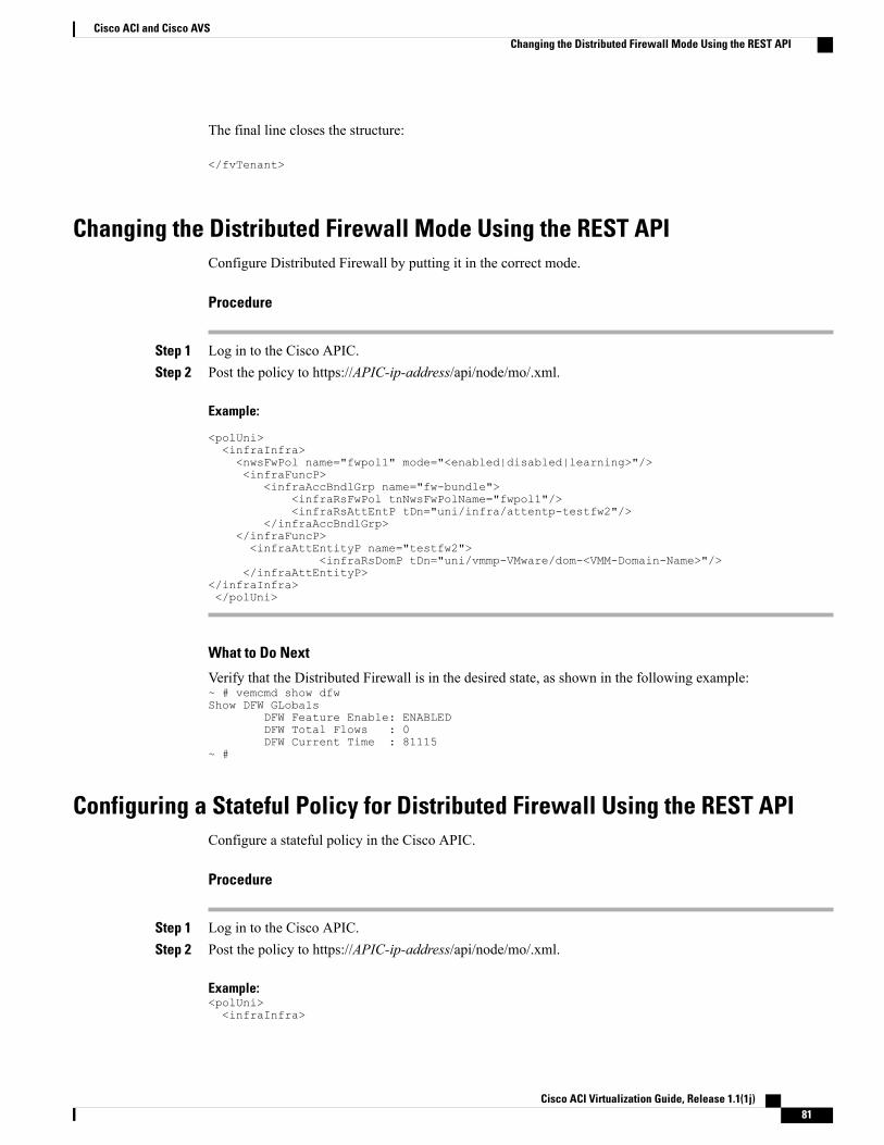
The final line closes the structure:
</fvTenant>
Changing the Distributed Firewall Mode Using the REST APIConfigure Distributed Firewall by putting it in the correct mode.
Procedure
Step 1 Log in to the Cisco APIC.Step 2 Post the policy to https://APIC-ip-address/api/node/mo/.xml.
Example:
<polUni><infraInfra><nwsFwPol name="fwpol1" mode="<enabled|disabled|learning>"/><infraFuncP>
<infraAccBndlGrp name="fw-bundle"><infraRsFwPol tnNwsFwPolName="fwpol1"/><infraRsAttEntP tDn="uni/infra/attentp-testfw2"/>
</infraAccBndlGrp></infraFuncP><infraAttEntityP name="testfw2">
<infraRsDomP tDn="uni/vmmp-VMware/dom-<VMM-Domain-Name>"/></infraAttEntityP>
</infraInfra></polUni>
What to Do Next
Verify that the Distributed Firewall is in the desired state, as shown in the following example:~ # vemcmd show dfwShow DFW GLobals
DFW Feature Enable: ENABLEDDFW Total Flows : 0DFW Current Time : 81115
~ #
Configuring a Stateful Policy for Distributed Firewall Using the REST APIConfigure a stateful policy in the Cisco APIC.
Procedure
Step 1 Log in to the Cisco APIC.Step 2 Post the policy to https://APIC-ip-address/api/node/mo/.xml.
Example:<polUni><infraInfra>
Cisco ACI Virtualization Guide, Release 1.1(1j) 81
Cisco ACI and Cisco AVSChanging the Distributed Firewall Mode Using the REST API
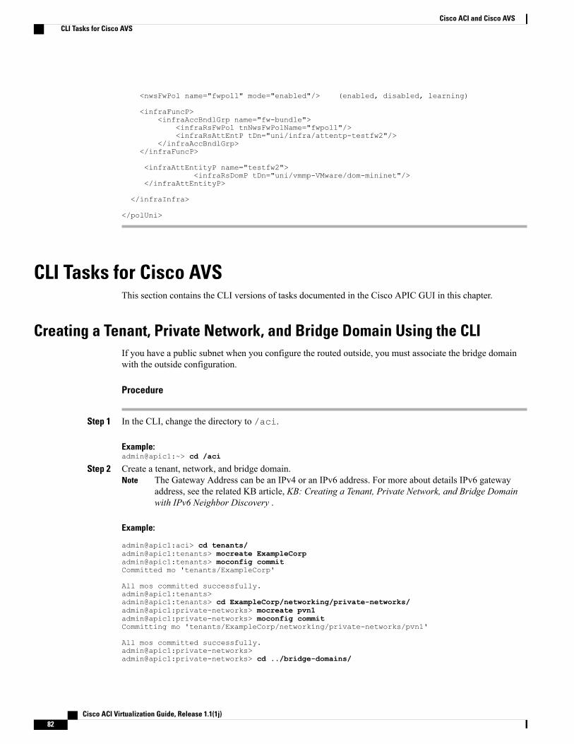
<nwsFwPol name="fwpol1" mode="enabled"/> (enabled, disabled, learning)
<infraFuncP><infraAccBndlGrp name="fw-bundle">
<infraRsFwPol tnNwsFwPolName="fwpol1"/><infraRsAttEntP tDn="uni/infra/attentp-testfw2"/>
</infraAccBndlGrp></infraFuncP>
<infraAttEntityP name="testfw2"><infraRsDomP tDn="uni/vmmp-VMware/dom-mininet"/>
</infraAttEntityP>
</infraInfra>
</polUni>
CLI Tasks for Cisco AVSThis section contains the CLI versions of tasks documented in the Cisco APIC GUI in this chapter.
Creating a Tenant, Private Network, and Bridge Domain Using the CLIIf you have a public subnet when you configure the routed outside, you must associate the bridge domainwith the outside configuration.
Procedure
Step 1 In the CLI, change the directory to /aci.
Example:admin@apic1:~> cd /aci
Step 2 Create a tenant, network, and bridge domain.The Gateway Address can be an IPv4 or an IPv6 address. For more about details IPv6 gatewayaddress, see the related KB article, KB: Creating a Tenant, Private Network, and Bridge Domainwith IPv6 Neighbor Discovery .
Note
Example:
admin@apic1:aci> cd tenants/admin@apic1:tenants> mocreate ExampleCorpadmin@apic1:tenants> moconfig commitCommitted mo 'tenants/ExampleCorp'
All mos committed successfully.admin@apic1:tenants>admin@apic1:tenants> cd ExampleCorp/networking/private-networks/admin@apic1:private-networks> mocreate pvn1admin@apic1:private-networks> moconfig commitCommitting mo 'tenants/ExampleCorp/networking/private-networks/pvn1'
All mos committed successfully.admin@apic1:private-networks>admin@apic1:private-networks> cd ../bridge-domains/
Cisco ACI Virtualization Guide, Release 1.1(1j)82
Cisco ACI and Cisco AVSCLI Tasks for Cisco AVS
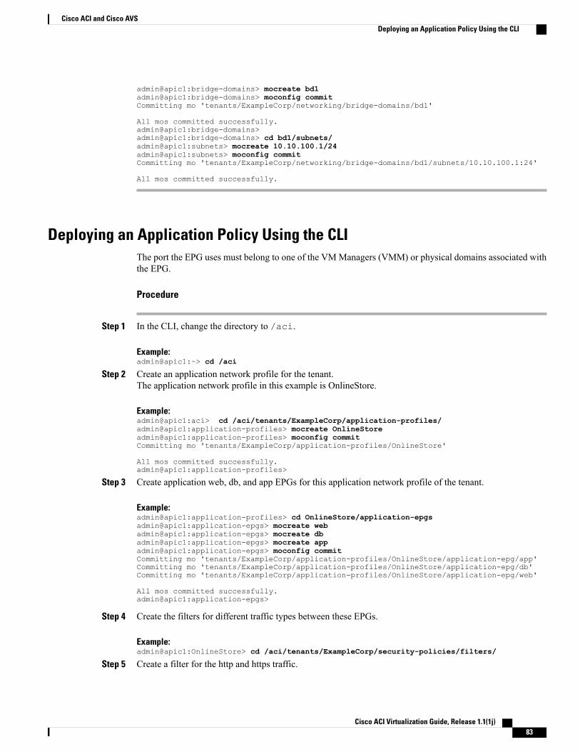
admin@apic1:bridge-domains> mocreate bd1admin@apic1:bridge-domains> moconfig commitCommitting mo 'tenants/ExampleCorp/networking/bridge-domains/bd1'
All mos committed successfully.admin@apic1:bridge-domains>admin@apic1:bridge-domains> cd bd1/subnets/admin@apic1:subnets> mocreate 10.10.100.1/24admin@apic1:subnets> moconfig commitCommitting mo 'tenants/ExampleCorp/networking/bridge-domains/bd1/subnets/10.10.100.1:24'
All mos committed successfully.
Deploying an Application Policy Using the CLIThe port the EPG uses must belong to one of the VMManagers (VMM) or physical domains associated withthe EPG.
Procedure
Step 1 In the CLI, change the directory to /aci.
Example:admin@apic1:~> cd /aci
Step 2 Create an application network profile for the tenant.The application network profile in this example is OnlineStore.
Example:admin@apic1:aci> cd /aci/tenants/ExampleCorp/application-profiles/admin@apic1:application-profiles> mocreate OnlineStoreadmin@apic1:application-profiles> moconfig commitCommitting mo 'tenants/ExampleCorp/application-profiles/OnlineStore'
All mos committed successfully.admin@apic1:application-profiles>
Step 3 Create application web, db, and app EPGs for this application network profile of the tenant.
Example:admin@apic1:application-profiles> cd OnlineStore/application-epgsadmin@apic1:application-epgs> mocreate webadmin@apic1:application-epgs> mocreate dbadmin@apic1:application-epgs> mocreate appadmin@apic1:application-epgs> moconfig commitCommitting mo 'tenants/ExampleCorp/application-profiles/OnlineStore/application-epg/app'Committing mo 'tenants/ExampleCorp/application-profiles/OnlineStore/application-epg/db'Committing mo 'tenants/ExampleCorp/application-profiles/OnlineStore/application-epg/web'
All mos committed successfully.admin@apic1:application-epgs>
Step 4 Create the filters for different traffic types between these EPGs.
Example:admin@apic1:OnlineStore> cd /aci/tenants/ExampleCorp/security-policies/filters/
Step 5 Create a filter for the http and https traffic.
Cisco ACI Virtualization Guide, Release 1.1(1j) 83
Cisco ACI and Cisco AVSDeploying an Application Policy Using the CLI
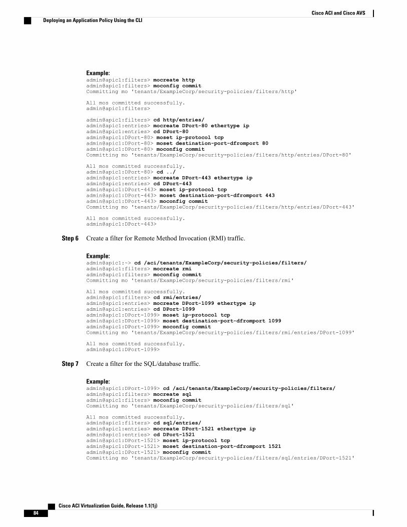
Example:admin@apic1:filters> mocreate httpadmin@apic1:filters> moconfig commitCommitting mo 'tenants/ExampleCorp/security-policies/filters/http'
All mos committed successfully.admin@apic1:filters>
admin@apic1:filters> cd http/entries/admin@apic1:entries> mocreate DPort-80 ethertype ipadmin@apic1:entries> cd DPort-80admin@apic1:DPort-80> moset ip-protocol tcpadmin@apic1:DPort-80> moset destination-port-dfromport 80admin@apic1:DPort-80> moconfig commitCommitting mo 'tenants/ExampleCorp/security-policies/filters/http/entries/DPort-80'
All mos committed successfully.admin@apic1:DPort-80> cd ../admin@apic1:entries> mocreate DPort-443 ethertype ipadmin@apic1:entries> cd DPort-443admin@apic1:DPort-443> moset ip-protocol tcpadmin@apic1:DPort-443> moset destination-port-dfromport 443admin@apic1:DPort-443> moconfig commitCommitting mo 'tenants/ExampleCorp/security-policies/filters/http/entries/DPort-443'
All mos committed successfully.admin@apic1:DPort-443>
Step 6 Create a filter for Remote Method Invocation (RMI) traffic.
Example:admin@apic1:~> cd /aci/tenants/ExampleCorp/security-policies/filters/admin@apic1:filters> mocreate rmiadmin@apic1:filters> moconfig commitCommitting mo 'tenants/ExampleCorp/security-policies/filters/rmi'
All mos committed successfully.admin@apic1:filters> cd rmi/entries/admin@apic1:entries> mocreate DPort-1099 ethertype ipadmin@apic1:entries> cd DPort-1099admin@apic1:DPort-1099> moset ip-protocol tcpadmin@apic1:DPort-1099> moset destination-port-dfromport 1099admin@apic1:DPort-1099> moconfig commitCommitting mo 'tenants/ExampleCorp/security-policies/filters/rmi/entries/DPort-1099'
All mos committed successfully.admin@apic1:DPort-1099>
Step 7 Create a filter for the SQL/database traffic.
Example:admin@apic1:DPort-1099> cd /aci/tenants/ExampleCorp/security-policies/filters/admin@apic1:filters> mocreate sqladmin@apic1:filters> moconfig commitCommitting mo 'tenants/ExampleCorp/security-policies/filters/sql'
All mos committed successfully.admin@apic1:filters> cd sql/entries/admin@apic1:entries> mocreate DPort-1521 ethertype ipadmin@apic1:entries> cd DPort-1521admin@apic1:DPort-1521> moset ip-protocol tcpadmin@apic1:DPort-1521> moset destination-port-dfromport 1521admin@apic1:DPort-1521> moconfig commitCommitting mo 'tenants/ExampleCorp/security-policies/filters/sql/entries/DPort-1521'
Cisco ACI Virtualization Guide, Release 1.1(1j)84
Cisco ACI and Cisco AVSDeploying an Application Policy Using the CLI

All mos committed successfully.admin@apic1:DPort-1521>
Step 8 Create the contracts and assign filters for RMI traffic between EPGs.
Example:admin@apic1:DPort-1521>admin@apic1:DPort-1521> cd /aci/tenants/ExampleCorp/security-policies/contracts/admin@apic1:contracts> mocreate rmiadmin@apic1:contracts> moconfig commitCommitting mo 'tenants/ExampleCorp/security-policies/contracts/rmi'
All mos committed successfully.admin@apic1:contracts> cd rmi/subjects/admin@apic1:subjects> mocreate rmiadmin@apic1:subjects> moconfig commitCommitting mo 'tenants/ExampleCorp/security-policies/contracts/rmi/subjects/rmi'
All mos committed successfully.admin@apic1:subjects> cd rmi/filters/admin@apic1:filters> mocreate rmiadmin@apic1:filters> moconfig commitCommitting mo 'tenants/ExampleCorp/security-policies/contracts/rmi/subjects/rmi/filters/rmi'
All mos committed successfully.admin@apic1:filters>
Step 9 Create the contracts and assign filters for web traffic between EPGs.
Example:admin@apic1:filters> cd /aci/tenants/ExampleCorp/security-policies/contracts/admin@apic1:contracts> mocreate webadmin@apic1:contracts> moconfig commitCommitting mo 'tenants/ExampleCorp/security-policies/contracts/web'
All mos committed successfully.admin@apic1:contracts> cd web/subjects/admin@apic1:subjects> mocreate webadmin@apic1:subjects> moconfig commitCommitting mo 'tenants/ExampleCorp/security-policies/contracts/web/subjects/web'
All mos committed successfully.admin@apic1:subjects> cd web/filters/admin@apic1:filters> mocreate httpadmin@apic1:filters> moconfig commitCommitting mo 'tenants/ExampleCorp/security-policies/contracts/web/subjects/web/filters/http'
All mos committed successfully.admin@apic1:filters>
Step 10 Create the contracts and assign filters for SQL traffic between EPGs.
Example:admin@apic1:filters> cd /aci/tenants/ExampleCorp/security-policies/contracts/admin@apic1:contracts> mocreate sqladmin@apic1:contracts> moconfig commitCommitting mo 'tenants/ExampleCorp/security-policies/contracts/sql'
All mos committed successfully.admin@apic1:contracts> cd sql/subjects/admin@apic1:subjects> mocreate sqladmin@apic1:subjects> moconfig commitCommitting mo 'tenants/ExampleCorp/security-policies/contracts/sql/subjects/sql'
All mos committed successfully.admin@apic1:subjects> cd sql/filters/
Cisco ACI Virtualization Guide, Release 1.1(1j) 85
Cisco ACI and Cisco AVSDeploying an Application Policy Using the CLI
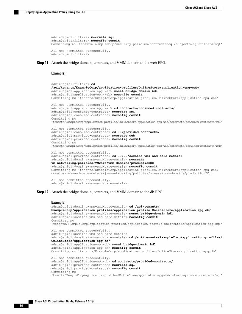
admin@apic1:filters> mocreate sqladmin@apic1:filters> moconfig commitCommitting mo 'tenants/ExampleCorp/security-policies/contracts/sql/subjects/sql/filters/sql'
All mos committed successfully.admin@apic1:filters>
Step 11 Attach the bridge domain, contracts, and VMM domain to the web EPG.
Example:
admin@apic1:filters> cd/aci/tenants/ExampleCorp/application-profiles/OnlineStore/application-epg-web/admin@apic1:application-epg-web> moset bridge-domain bd1admin@apic1:application-epg-web> moconfig commitCommitting mo 'tenants/ExampleCorp/application-profiles/OnlineStore/application-epg-web'
All mos committed successfully.admin@apic1:application-epg-web> cd contracts/consumed-contracts/admin@apic1:consumed-contracts> mocreate rmiadmin@apic1:consumed-contracts> moconfig commitCommitting mo'tenants/ExampleCorp/application-profiles/OnlineStore/application-epg-web/contracts/consumed-contracts/rmi'
All mos committed successfully.admin@apic1:consumed-contracts> cd ../provided-contracts/admin@apic1:provided-contracts> mocreate webadmin@apic1:provided-contracts> moconfig commitCommitting mo'tenants/ExampleCorp/application-profiles/OnlineStore/application-epg-web/contracts/provided-contracts/web'
All mos committed successfully.admin@apic1:provided-contracts> cd ../../domains-vms-and-bare-metals/admin@apic1:domains-vms-and-bare-metals> mocreatevm-networking/policies/VMware/vmm-domains/productionDCadmin@apic1:domains-vms-and-bare-metals> moconfig commitCommitting mo 'tenants/ExampleCorp/application-profiles/OnlineStore/application-epg-web/domains-vms-and-bare-metals/[vm-networking/policies/vmware/vmm-domains/productionDC]'
All mos committed successfully.admin@apic1:domains-vms-and-bare-metals>
Step 12 Attach the bridge domain, contracts, and VMM domain to the db EPG.
Example:admin@apic1:domains-vms-and-bare-metals> cd /aci/tenants/ExampleCorp/application-profiles/application-profile-OnlineStore/application-epg-db/admin@apic1:domains-vms-and-bare-metals> moset bridge-domain bd1admin@apic1:domains-vms-and-bare-metals> moconfig commitCommitted mo'tenants/ExampleCorp/application-profiles/application-profile-OnlineStore/application-epg-sql'
All mos committed successfully.admin@apic1:domains-vms-and-bare-metals>admin@apic1:domains-vms-and-bare-metals> cd /aci/tenants/ExampleCorp/application-profiles/OnlineStore/application-epg-db/admin@apic1:application-epg-db> moset bridge-domain bd1admin@apic1:application-epg-db> moconfig commitCommitting mo 'tenants/ExampleCorp/application-profiles/OnlineStore/application-epg-db'
All mos committed successfully.admin@apic1:application-epg-db> cd contracts/provided-contracts/admin@apic1:provided-contracts> mocreate sqladmin@apic1:provided-contracts> moconfig commitCommitting mo'tenants/ExampleCorp/application-profiles/OnlineStore/application-epg-db/contracts/provided-contracts/sql'
Cisco ACI Virtualization Guide, Release 1.1(1j)86
Cisco ACI and Cisco AVSDeploying an Application Policy Using the CLI
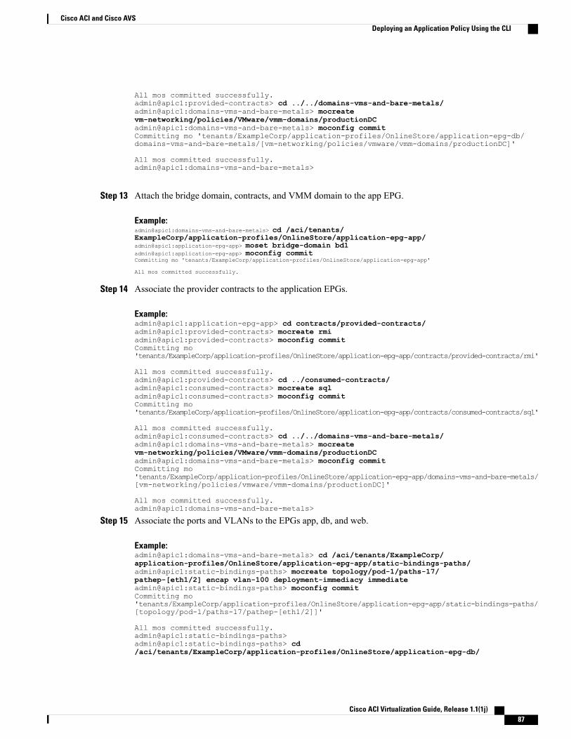
All mos committed successfully.admin@apic1:provided-contracts> cd ../../domains-vms-and-bare-metals/admin@apic1:domains-vms-and-bare-metals> mocreatevm-networking/policies/VMware/vmm-domains/productionDCadmin@apic1:domains-vms-and-bare-metals> moconfig commitCommitting mo 'tenants/ExampleCorp/application-profiles/OnlineStore/application-epg-db/domains-vms-and-bare-metals/[vm-networking/policies/vmware/vmm-domains/productionDC]'
All mos committed successfully.admin@apic1:domains-vms-and-bare-metals>
Step 13 Attach the bridge domain, contracts, and VMM domain to the app EPG.
Example:admin@apic1:domains-vms-and-bare-metals> cd /aci/tenants/ExampleCorp/application-profiles/OnlineStore/application-epg-app/admin@apic1:application-epg-app> moset bridge-domain bd1admin@apic1:application-epg-app> moconfig commitCommitting mo 'tenants/ExampleCorp/application-profiles/OnlineStore/application-epg-app'
All mos committed successfully.
Step 14 Associate the provider contracts to the application EPGs.
Example:admin@apic1:application-epg-app> cd contracts/provided-contracts/admin@apic1:provided-contracts> mocreate rmiadmin@apic1:provided-contracts> moconfig commitCommitting mo'tenants/ExampleCorp/application-profiles/OnlineStore/application-epg-app/contracts/provided-contracts/rmi'
All mos committed successfully.admin@apic1:provided-contracts> cd ../consumed-contracts/admin@apic1:consumed-contracts> mocreate sqladmin@apic1:consumed-contracts> moconfig commitCommitting mo'tenants/ExampleCorp/application-profiles/OnlineStore/application-epg-app/contracts/consumed-contracts/sql'
All mos committed successfully.admin@apic1:consumed-contracts> cd ../../domains-vms-and-bare-metals/admin@apic1:domains-vms-and-bare-metals> mocreatevm-networking/policies/VMware/vmm-domains/productionDCadmin@apic1:domains-vms-and-bare-metals> moconfig commitCommitting mo'tenants/ExampleCorp/application-profiles/OnlineStore/application-epg-app/domains-vms-and-bare-metals/[vm-networking/policies/vmware/vmm-domains/productionDC]'
All mos committed successfully.admin@apic1:domains-vms-and-bare-metals>
Step 15 Associate the ports and VLANs to the EPGs app, db, and web.
Example:admin@apic1:domains-vms-and-bare-metals> cd /aci/tenants/ExampleCorp/application-profiles/OnlineStore/application-epg-app/static-bindings-paths/admin@apic1:static-bindings-paths> mocreate topology/pod-1/paths-17/pathep-[eth1/2] encap vlan-100 deployment-immediacy immediateadmin@apic1:static-bindings-paths> moconfig commitCommitting mo'tenants/ExampleCorp/application-profiles/OnlineStore/application-epg-app/static-bindings-paths/[topology/pod-1/paths-17/pathep-[eth1/2]]'
All mos committed successfully.admin@apic1:static-bindings-paths>admin@apic1:static-bindings-paths> cd/aci/tenants/ExampleCorp/application-profiles/OnlineStore/application-epg-db/
Cisco ACI Virtualization Guide, Release 1.1(1j) 87
Cisco ACI and Cisco AVSDeploying an Application Policy Using the CLI
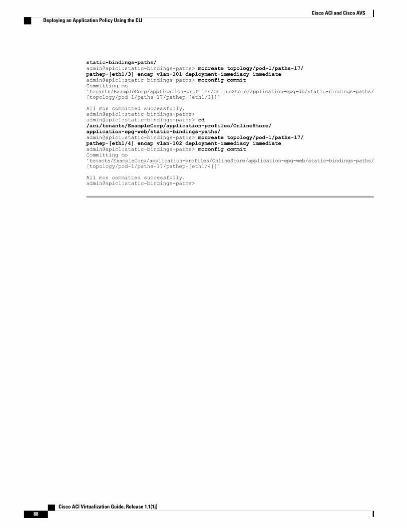
static-bindings-paths/admin@apic1:static-bindings-paths> mocreate topology/pod-1/paths-17/pathep-[eth1/3] encap vlan-101 deployment-immediacy immediateadmin@apic1:static-bindings-paths> moconfig commitCommitting mo'tenants/ExampleCorp/application-profiles/OnlineStore/application-epg-db/static-bindings-paths/[topology/pod-1/paths-17/pathep-[eth1/3]]'
All mos committed successfully.admin@apic1:static-bindings-paths>admin@apic1:static-bindings-paths> cd/aci/tenants/ExampleCorp/application-profiles/OnlineStore/application-epg-web/static-bindings-paths/admin@apic1:static-bindings-paths> mocreate topology/pod-1/paths-17/pathep-[eth1/4] encap vlan-102 deployment-immediacy immediateadmin@apic1:static-bindings-paths> moconfig commitCommitting mo'tenants/ExampleCorp/application-profiles/OnlineStore/application-epg-web/static-bindings-paths/[topology/pod-1/paths-17/pathep-[eth1/4]]'
All mos committed successfully.admin@apic1:static-bindings-paths>
Cisco ACI Virtualization Guide, Release 1.1(1j)88
Cisco ACI and Cisco AVSDeploying an Application Policy Using the CLI
C H A P T E R 4Cisco ACI with Microsoft SCVMM
This chapter contains the following sections:
• About Cisco ACI with Microsoft SCVMM, page 89
• Getting Started with Cisco ACI with Microsoft SCVMM, page 91
• Deploying Tenant Policies, page 104
• Troubleshooting the Cisco ACI with Microsoft SCVMM, page 108
• REST API References, page 109
• Command-Line Interface References, page 113
• Programmability References, page 118
• Uninstalling the Cisco ACI with Microsoft SCVMM Components, page 118
• Downgrading the APIC Controller and the Switch Software with Cisco ACI with Microsoft SCVMMComponents, page 120
About Cisco ACI with Microsoft SCVMMThe Application Policy Infrastructure Controller (APIC) integrates with Microsoft VMmanagement systemsand enhances the networkmanagement capabilities of the platform. The CiscoApplication Centric Infrastructure(ACI) integrates in one of two modes and you can choose either one based on your deployments:
• Cisco ACI with Microsoft System Center Virtual Machine Manager (SCVMM)—When integrated withCisco ACI, SCVMM enables communication between ACI and SCVMM for network management.
• Cisco ACI and Microsoft Windows Azure Pack—For information about how to set up Cisco ACI andMicrosoftWindowsAzure Pack, see CiscoACIwithMicrosoftWindowsAzure Pack SolutionOverview,on page 122.
Cisco ACI with Microsoft SCVMM Solution OverviewIn this mode the Application Policy Infrastructure Controller (APIC) and Microsoft System Center VirtualMachineManager (SCVMM) communicate with each other for networkmanagement. Endpoint groups (EPGs)
Cisco ACI Virtualization Guide, Release 1.1(1j) 89
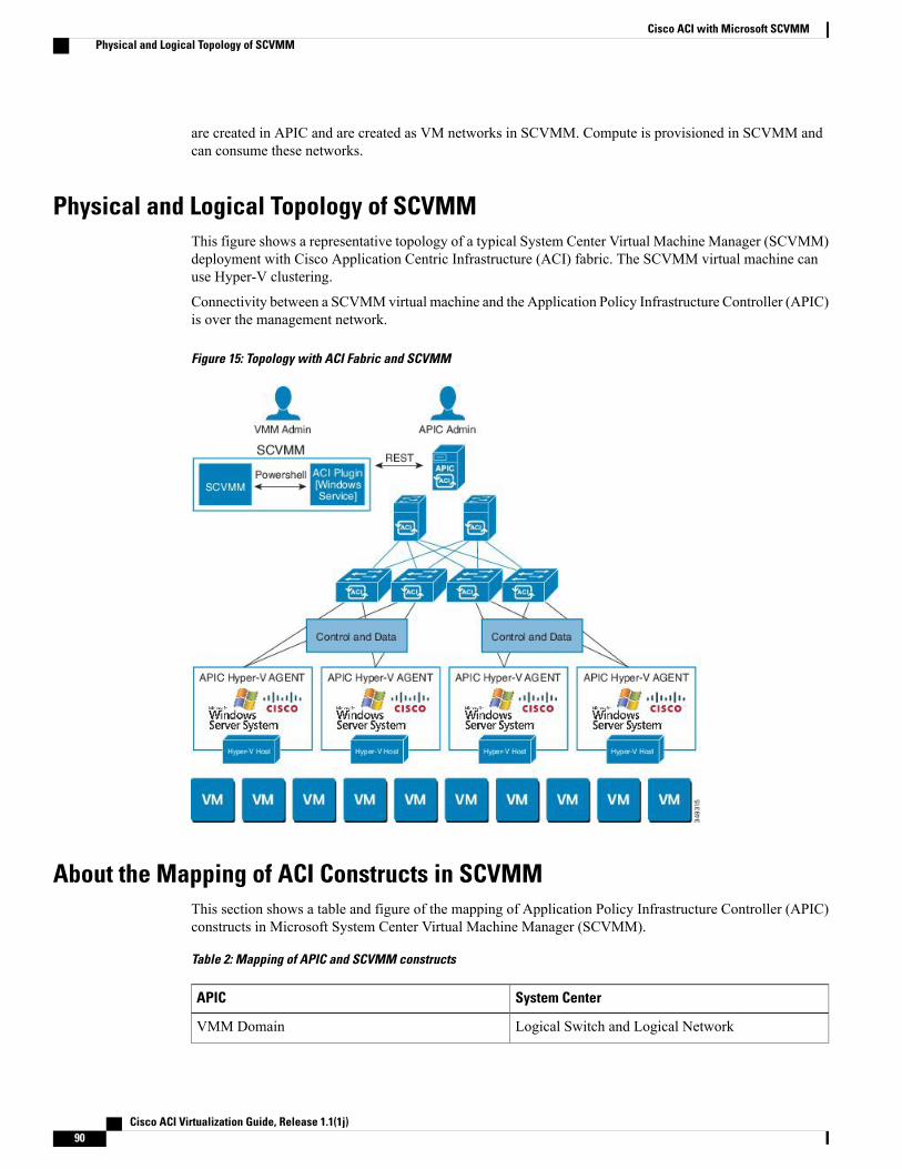
are created in APIC and are created as VM networks in SCVMM. Compute is provisioned in SCVMM andcan consume these networks.
Physical and Logical Topology of SCVMMThis figure shows a representative topology of a typical System Center Virtual Machine Manager (SCVMM)deployment with Cisco Application Centric Infrastructure (ACI) fabric. The SCVMM virtual machine canuse Hyper-V clustering.
Connectivity between a SCVMMvirtual machine and the Application Policy Infrastructure Controller (APIC)is over the management network.
Figure 15: Topology with ACI Fabric and SCVMM
About the Mapping of ACI Constructs in SCVMMThis section shows a table and figure of the mapping of Application Policy Infrastructure Controller (APIC)constructs in Microsoft System Center Virtual Machine Manager (SCVMM).
Table 2: Mapping of APIC and SCVMM constructs
System CenterAPIC
Logical Switch and Logical NetworkVMM Domain
Cisco ACI Virtualization Guide, Release 1.1(1j)90
Cisco ACI with Microsoft SCVMMPhysical and Logical Topology of SCVMM
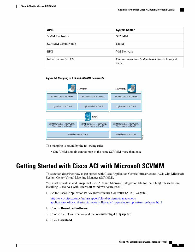
System CenterAPIC
SCVMMVMM Controller
CloudSCVMM Cloud Name
VM NetworkEPG
One infrastructure VM network for each logicalswitch
Infrastructure VLAN
Figure 16: Mapping of ACI and SCVMM constructs
The mapping is bound by the following rule:
• One VMM domain cannot map to the same SCVMM more than once.
Getting Started with Cisco ACI with Microsoft SCVMMThis section describes how to get started with Cisco Application Centric Infrastructure (ACI) with MicrosoftSystem Center Virtual Machine Manager (SCVMM).
You must download and unzip the Cisco ACI and Microsoft Integration file for the 1.1(1j) release beforeinstalling Cisco ACI with Microsoft Windows Azure Pack.
1 Go to Cisco's Application Policy Infrastructure Controller (APIC) Website:
http://www.cisco.com/c/en/us/support/cloud-systems-management/application-policy-infrastructure-controller-apic/tsd-products-support-series-home.html
2 Choose Download Software.
3 Choose the release version and the aci-msft-pkg-1.1.1j.zip file.
4 Click Download.
Cisco ACI Virtualization Guide, Release 1.1(1j) 91
Cisco ACI with Microsoft SCVMMGetting Started with Cisco ACI with Microsoft SCVMM
5 Unzip the aci-msft-pkg-1.1.1j.zip file.
Cisco ACI with Microsoft System Center Virtual Machine Manager (SCVMM) only supports ASCIIcharacters. Non-ASCII characters are not supported.
Note
Prerequisites for Getting Started with Cisco ACI with Microsoft SCVMMBefore you get started, ensure that you have verified that your computing environment meets the followingprerequisites:
• Ensure Microsoft System Center 2012 R2 - Virtual Machine Manager (SCVMM) with Update Rollup5 is installed.
See Microsoft's documentation.
• Ensure Windows Server 2012 R2 is installed on the Hyper-V server with the Hyper-V role enabled.
See Microsoft's documentation.
• Ensure the cloud is configured in SCVMM and appropriate hosts added to that cloud.
See Microsoft's documentation.
• Ensure "default" AEP exists with infrastructure VLAN enabled.
• Ensure you have the Cisco MSI files for APIC SCVMM and the Host Agent.
See Getting Started with Cisco ACI with Microsoft SCVMM, on page 91.
Installing, Setting Up, and Verifying the Cisco ACI with Microsoft SCVMMComponents
This section describes how to install, set up, and verify the Cisco Application Centric Infrastructure (ACI)with Microsoft System Center Virtual Machine Manager (SCVMM) components.
TaskComponent
See Installing theAPIC SCVMMAgent on SCVMM,on page 93.
For the Windows Command Prompt method, seeInstalling the APIC Agent on SCVMM Using theWindows Command Prompt, on page 113.
Install the APIC SCVMM Agent on SCVMM
See Configuring APIC IP Settings with APICCredentials on the SCVMM Agent, on page 94.
Configure APIC IP Settings with APIC credentialson the SCVMM Agent
See Generating APIC Hyper-V Agent OpFlexCertificate, on page 95.
Generate the APICHyper-VAgent OpFlex certificate
Cisco ACI Virtualization Guide, Release 1.1(1j)92
Cisco ACI with Microsoft SCVMMPrerequisites for Getting Started with Cisco ACI with Microsoft SCVMM
TaskComponent
See Adding the OpFlex Certificate Policy to APIC,on page 96.
Add the OpFlex certificate policy to APIC
See Installing the APIC Hyper-V Agent on theHyper-V Server, on page 97.
For the Windows Command Prompt method, seeInstalling the APIC Hyper-V Agent on the Hyper-VServer Using the Windows Command Prompt, onpage 114.
Install the APIC Hyper-V Agent on the Hyper-Vserver
See Verifying the APIC SCVMM Agent Installationon SCVMM, on page 100.
Verify the APIC SCVMM Agent installation onSCVMM
See Verifying the APIC Hyper-V Agent Installationon the Hyper-V Server, on page 100.
Verify the APIC Hyper-V Agent installation on theHyper-V server
See Creating SCVMMDomain Profiles, on page 101and Creating a SCVMM Domain Profile Using theGUI, on page 101.
For the CLImethod, see Creating a SCVMMDomainProfile Using the CLI, on page 115.
For the REST API method, see Creating a SCVMMDomain Profile Using the REST API, on page 109.
Create SCVMM Domain Profiles
See Verifying the SCVMM VMM Domain andSCVMM VMM, on page 103.
Verify the SCVMM VMM Domain and SCVMMVMM
See Deploying the Logical Switch to the Host onSCVMM, on page 103.
Deploy the logical switch to the host on SCVMM
Installing the APIC SCVMM Agent on SCVMMThis section describes how to install the Application Policy Infrastructure Controller (APIC) SCVMM agenton System Center Virtual Machine Manager (SCVMM).
Procedure
Step 1 Log in to the SCVMM server with SCVMM administrator credentials.Step 2 On the SCVMM server in Explorer, locate the APIC SCVMM Agent.msi file.Step 3 Right-click APIC SCVMM Agent.msi file and select Install.Step 4 In the Cisco APIC SCVMM Agent Setup dialog box, perform the following actions:
a) Click Next.b) Check the I accept the terms in the License Agreement check box and click Next.
Cisco ACI Virtualization Guide, Release 1.1(1j) 93
Cisco ACI with Microsoft SCVMMInstalling, Setting Up, and Verifying the Cisco ACI with Microsoft SCVMM Components
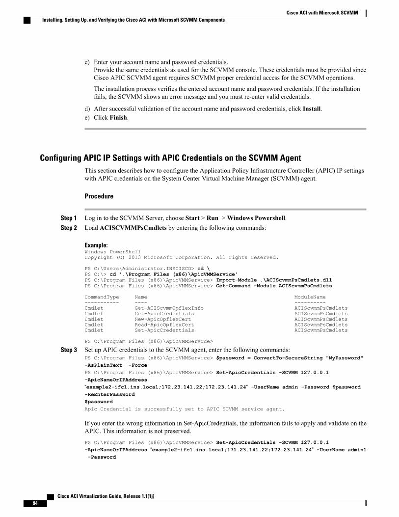
c) Enter your account name and password credentials.Provide the same credentials as used for the SCVMM console. These credentials must be provided sinceCisco APIC SCVMM agent requires SCVMM proper credential access for the SCVMM operations.
The installation process verifies the entered account name and password credentials. If the installationfails, the SCVMM shows an error message and you must re-enter valid credentials.
d) After successful validation of the account name and password credentials, click Install.e) Click Finish.
Configuring APIC IP Settings with APIC Credentials on the SCVMM AgentThis section describes how to configure the Application Policy Infrastructure Controller (APIC) IP settingswith APIC credentials on the System Center Virtual Machine Manager (SCVMM) agent.
Procedure
Step 1 Log in to the SCVMM Server, choose Start > Run >Windows Powershell.Step 2 Load ACISCVMMPsCmdlets by entering the following commands:
Example:Windows PowerShellCopyright (C) 2013 Microsoft Corporation. All rights reserved.
PS C:\Users\Administrator.INSCISCO> cd \PS C:\> cd '.\Program Files (x86)\ApicVMMService'PS C:\Program Files (x86)\ApicVMMService> Import-Module .\ACIScvmmPsCmdlets.dllPS C:\Program Files (x86)\ApicVMMService> Get-Command -Module ACIScvmmPsCmdlets
CommandType Name ModuleName----------- ---- ----------Cmdlet Get-ACIScvmmOpflexInfo ACIScvmmPsCmdletsCmdlet Get-ApicCredentials ACIScvmmPsCmdletsCmdlet New-ApicOpflexCert ACIScvmmPsCmdletsCmdlet Read-ApicOpflexCert ACIScvmmPsCmdletsCmdlet Set-ApicCredentials ACIScvmmPsCmdlets
PS C:\Program Files (x86)\ApicVMMService>
Step 3 Set up APIC credentials to the SCVMM agent, enter the following commands:PS C:\Program Files (x86)\ApicVMMService> $password = ConvertTo-SecureString "MyPassword"-AsPlainText -ForcePS C:\Program Files (x86)\ApicVMMService> Set-ApicCredentials -SCVMM 127.0.0.1-ApicNameOrIPAddress“example2-ifc1.ins.local;172.23.141.22;172.23.141.24” -UserName admin -Password $password-ReEnterPassword$passwordApic Credential is successfully set to APIC SCVMM service agent.
If you enter the wrong information in Set-ApicCredentials, the information fails to apply and validate on theAPIC. This information is not preserved.
PS C:\Program Files (x86)\ApicVMMService> Set-ApicCredentials -SCVMM 127.0.0.1-ApicNameOrIPAddress “example2-ifc1.ins.local;171.23.141.22;172.23.141.24” -UserName admin1-Password
Cisco ACI Virtualization Guide, Release 1.1(1j)94
Cisco ACI with Microsoft SCVMMInstalling, Setting Up, and Verifying the Cisco ACI with Microsoft SCVMM Components
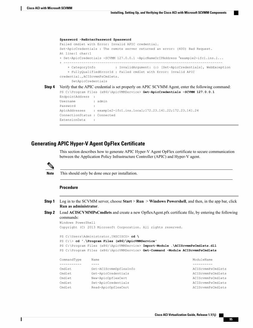
$password -ReEnterPassword $passwordFailed cmdlet with Error: Invalid APIC credential.Set-ApicCredentials : The remote server returned an error: (400) Bad Request.At line:1 char:1+ Set-ApicCredentials -SCVMM 127.0.0.1 -ApicNameOrIPAddress “example2-ifc1.ins.l...+ ~~~~~~~~~~~~~~~~~~~~~~~~~~~~~~~~~~~~~~~~~~~~~~~~~~~~~~~~~~~~~~~~~~~~~~~~~~~~~~~~
+ CategoryInfo : InvalidArgument: (:) [Set-ApicCredentials], WebException+ FullyQualifiedErrorId : Failed cmdlet with Error: Invalid APIC
credential.,ACIScvmmPsCmdlets.SetApicCredentials
Step 4 Verify that the APIC credential is set properly on APIC SCVMM Agent, enter the following command:PS C:\Program Files (x86)\ApicVMMService> Get-ApicCredentials -SCVMM 127.0.0.1EndpointAddress :Username : adminPassword :ApicAddresses : example2-ifc1.ins.local;172.23.141.22;172.23.141.24ConnectionStatus : ConnectedExtensionData :
Generating APIC Hyper-V Agent OpFlex CertificateThis section describes how to generate APIC Hyper-V Agent OpFlex certificate to secure communicationbetween the Application Policy Infrastructure Controller (APIC) and Hyper-V agent.
This should only be done once per installation.Note
Procedure
Step 1 Log in to the SCVMM server, choose Start > Run >Windows Powershell, and then, in the app bar, clickRun as administrator.
Step 2 Load ACISCVMMPsCmdlets and create a new OpflexAgent.pfx certificate file, by entering the followingcommands:Windows PowerShellCopyright (C) 2013 Microsoft Corporation. All rights reserved.
PS C:\Users\Administrator.INSCISCO> cd \PS C:\> cd '.\Program Files (x86)\ApicVMMService'PS C:\Program Files (x86)\ApicVMMService> Import-Module .\ACIScvmmPsCmdlets.dllPS C:\Program Files (x86)\ApicVMMService> Get-Command -Module ACIScvmmPsCmdlets
CommandType Name ModuleName----------- ---- ----------Cmdlet Get-ACIScvmmOpflexInfo ACIScvmmPsCmdletsCmdlet Get-ApicCredentials ACIScvmmPsCmdletsCmdlet New-ApicOpflexCert ACIScvmmPsCmdletsCmdlet Set-ApicCredentials ACIScvmmPsCmdletsCmdlet Read-ApicOpflexCert ACIScvmmPsCmdlets
Cisco ACI Virtualization Guide, Release 1.1(1j) 95
Cisco ACI with Microsoft SCVMMInstalling, Setting Up, and Verifying the Cisco ACI with Microsoft SCVMM Components
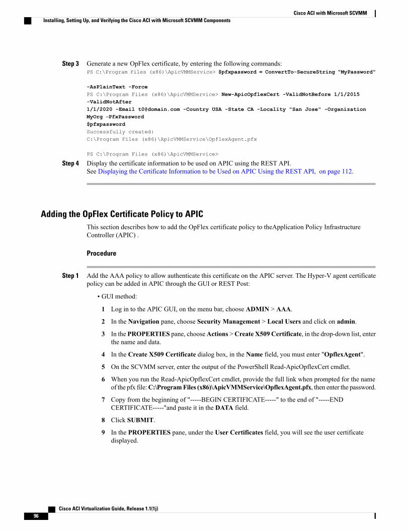
Step 3 Generate a new OpFlex certificate, by entering the following commands:PS C:\Program Files (x86)\ApicVMMService> $pfxpassword = ConvertTo-SecureString "MyPassword"
-AsPlainText -ForcePS C:\Program Files (x86)\ApicVMMService> New-ApicOpflexCert -ValidNotBefore 1/1/2015-ValidNotAfter1/1/2020 -Email [email protected] -Country USA -State CA -Locality "San Jose" -OrganizationMyOrg –PfxPassword$pfxpasswordSuccessfully created:C:\Program Files (x86)\ApicVMMService\OpflexAgent.pfx
PS C:\Program Files (x86)\ApicVMMService>
Step 4 Display the certificate information to be used on APIC using the REST API.See Displaying the Certificate Information to be Used on APIC Using the REST API, on page 112.
Adding the OpFlex Certificate Policy to APICThis section describes how to add the OpFlex certificate policy to theApplication Policy InfrastructureController (APIC) .
Procedure
Step 1 Add the AAA policy to allow authenticate this certificate on the APIC server. The Hyper-V agent certificatepolicy can be added in APIC through the GUI or REST Post:
• GUI method:
1 Log in to the APIC GUI, on the menu bar, choose ADMIN > AAA.
2 In the Navigation pane, choose Security Management > Local Users and click on admin.
3 In the PROPERTIES pane, chooseActions >Create X509 Certificate, in the drop-down list, enterthe name and data.
4 In the Create X509 Certificate dialog box, in the Name field, you must enter "OpflexAgent".
5 On the SCVMM server, enter the output of the PowerShell Read-ApicOpflexCert cmdlet.
6 When you run the Read-ApicOpflexCert cmdlet, provide the full link when prompted for the nameof the pfx file:C:\ProgramFiles (x86)\ApicVMMService\OpflexAgent.pfx, then enter the password.
7 Copy from the beginning of "-----BEGIN CERTIFICATE-----" to the end of "-----ENDCERTIFICATE-----"and paste it in the DATA field.
8 Click SUBMIT.
9 In the PROPERTIES pane, under the User Certificates field, you will see the user certificatedisplayed.
Cisco ACI Virtualization Guide, Release 1.1(1j)96
Cisco ACI with Microsoft SCVMMInstalling, Setting Up, and Verifying the Cisco ACI with Microsoft SCVMM Components
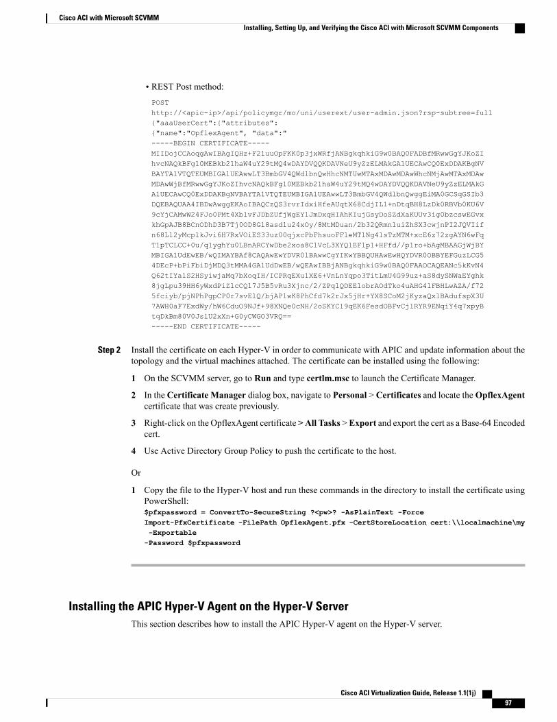
• REST Post method:
POSThttp://<apic-ip>/api/policymgr/mo/uni/userext/user-admin.json?rsp-subtree=full{"aaaUserCert":{"attributes":{"name":"OpflexAgent", "data":"-----BEGIN CERTIFICATE-----MIIDojCCAoqgAwIBAgIQHz+F2luuOpFKK0p3jxWRfjANBgkqhkiG9w0BAQ0FADBfMRwwGgYJKoZIhvcNAQkBFg10MEBkb21haW4uY29tMQ4wDAYDVQQKDAVNeU9yZzELMAkGA1UECAwCQ0ExDDAKBgNVBAYTA1VTQTEUMBIGA1UEAwwLT3BmbGV4QWdlbnQwHhcNMTUwMTAxMDAwMDAwWhcNMjAwMTAxMDAwMDAwWjBfMRwwGgYJKoZIhvcNAQkBFg10MEBkb21haW4uY29tMQ4wDAYDVQQKDAVNeU9yZzELMAkGA1UECAwCQ0ExDDAKBgNVBAYTA1VTQTEUMBIGA1UEAwwLT3BmbGV4QWdlbnQwggEiMA0GCSqGSIb3DQEBAQUAA4IBDwAwggEKAoIBAQCzQS3rvrIdxiHfeAUqtX68CdjIL1+nDtqBH8LzDk0RBVb0KU6V9cYjCAMwW24FJo0PMt4XblvFJDbZUfjWgEY1JmDxqHIAhKIujGsyDoSZdXaKUUv3ig0bzcswEGvxkhGpAJB8BCnODhD3B7Tj0OD8Gl8asd1u24xOy/8MtMDuan/2b32QRmn1uiZhSX3cwjnPI2JQVIifn68L12yMcp1kJvi6H7RxVOiES33uz00qjxcPbFhsuoFF1eMT1Ng41sTzMTM+xcE6z72zgAYN6wFqT1pTCLCC+0u/q1yghYu0LBnARCYwDbe2xoa8ClVcL3XYQlEFlp1+HFfd//p1ro+bAgMBAAGjWjBYMBIGA1UdEwEB/wQIMAYBAf8CAQAwEwYDVR0lBAwwCgYIKwYBBQUHAwEwHQYDVR0OBBYEFGuzLCG54DEcP+bPiFbiDjMDQ3tMMA4GA1UdDwEB/wQEAwIBBjANBgkqhkiG9w0BAQ0FAAOCAQEANc5kKvN4Q62tIYa1S2HSyiwjaMq7bXoqIH/ICPRqEXu1XE6+VnLnYqpo3TitLmU4G99uz+aS8dySNWaEYghk8jgLpu39HH6yWxdPiZlcCQ17J5B5vRu3Xjnc/2/ZPqlQDEElobrAOdTko4uAHG4lFBHLwAZA/f725fciyb/pjNPhPgpCP0r7svElQ/bjAP1wK8PhCfd7k2rJx5jHr+YX8SCoM2jKyzaQx1BAdufspX3U7AWH0aF7ExdWy/hW6CduO9NJf+98XNQe0cNH/2oSKYCl9qEK6FesdOBFvCjlRYR9ENqiY4q7xpyBtqDkBm80V0JslU2xXn+G0yCWGO3VRQ==-----END CERTIFICATE-----
Step 2 Install the certificate on each Hyper-V in order to communicate with APIC and update information about thetopology and the virtual machines attached. The certificate can be installed using the following:
1 On the SCVMM server, go to Run and type certlm.msc to launch the Certificate Manager.
2 In the Certificate Manager dialog box, navigate to Personal > Certificates and locate theOpflexAgentcertificate that was create previously.
3 Right-click on the OpflexAgent certificate >All Tasks >Export and export the cert as a Base-64 Encodedcert.
4 Use Active Directory Group Policy to push the certificate to the host.
Or
1 Copy the file to the Hyper-V host and run these commands in the directory to install the certificate usingPowerShell:$pfxpassword = ConvertTo-SecureString ?<pw>? -AsPlainText -ForceImport-PfxCertificate -FilePath OpflexAgent.pfx -CertStoreLocation cert:\\localmachine\my-Exportable-Password $pfxpassword
Installing the APIC Hyper-V Agent on the Hyper-V ServerThis section describes how to install the APIC Hyper-V agent on the Hyper-V server.
Cisco ACI Virtualization Guide, Release 1.1(1j) 97
Cisco ACI with Microsoft SCVMMInstalling, Setting Up, and Verifying the Cisco ACI with Microsoft SCVMM Components
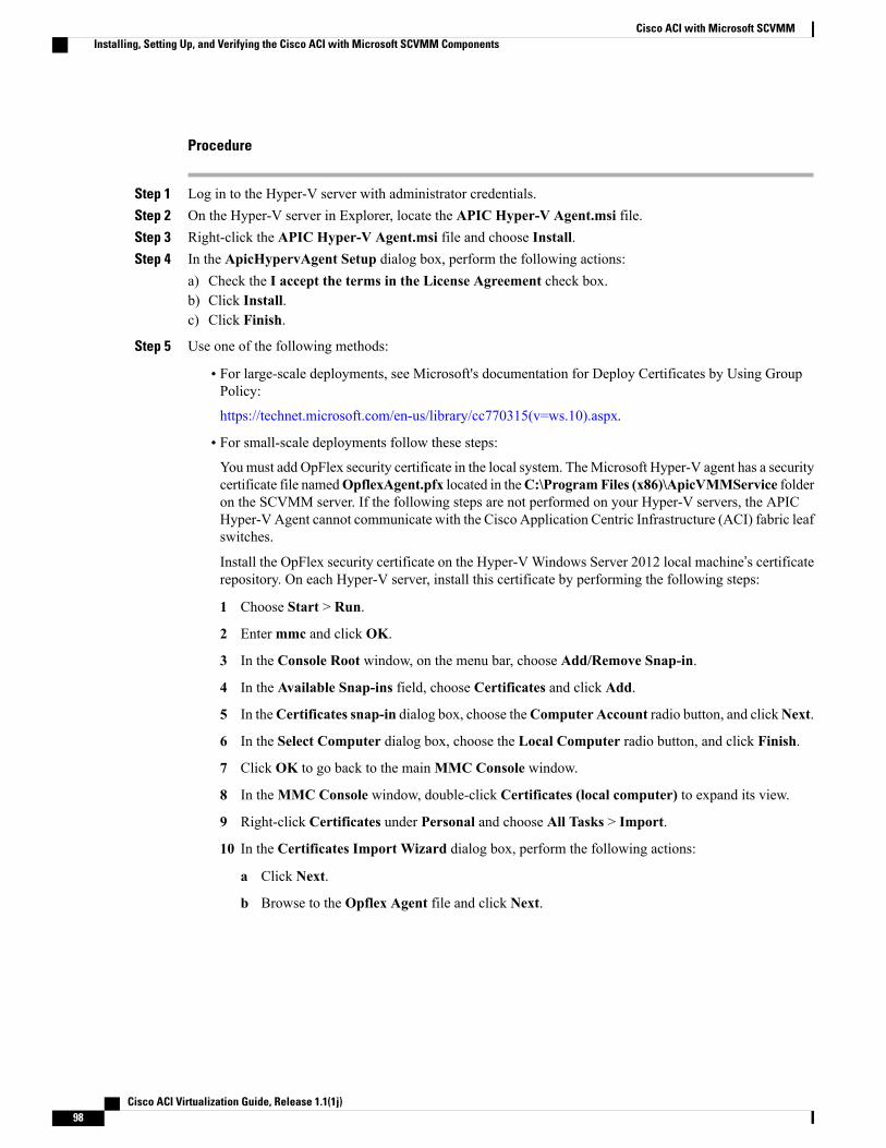
Procedure
Step 1 Log in to the Hyper-V server with administrator credentials.Step 2 On the Hyper-V server in Explorer, locate the APIC Hyper-V Agent.msi file.Step 3 Right-click the APIC Hyper-V Agent.msi file and choose Install.Step 4 In the ApicHypervAgent Setup dialog box, perform the following actions:
a) Check the I accept the terms in the License Agreement check box.b) Click Install.c) Click Finish.
Step 5 Use one of the following methods:
• For large-scale deployments, see Microsoft's documentation for Deploy Certificates by Using GroupPolicy:
https://technet.microsoft.com/en-us/library/cc770315(v=ws.10).aspx.
• For small-scale deployments follow these steps:
Youmust add OpFlex security certificate in the local system. TheMicrosoft Hyper-V agent has a securitycertificate file namedOpflexAgent.pfx located in theC:\ProgramFiles (x86)\ApicVMMService folderon the SCVMM server. If the following steps are not performed on your Hyper-V servers, the APICHyper-V Agent cannot communicate with the Cisco Application Centric Infrastructure (ACI) fabric leafswitches.
Install the OpFlex security certificate on the Hyper-V Windows Server 2012 local machine’s certificaterepository. On each Hyper-V server, install this certificate by performing the following steps:
1 Choose Start > Run.
2 Entermmc and click OK.
3 In the Console Root window, on the menu bar, choose Add/Remove Snap-in.
4 In the Available Snap-ins field, choose Certificates and click Add.
5 In theCertificates snap-in dialog box, choose theComputer Account radio button, and clickNext.
6 In the Select Computer dialog box, choose the Local Computer radio button, and click Finish.
7 Click OK to go back to the mainMMC Console window.
8 In theMMC Console window, double-click Certificates (local computer) to expand its view.
9 Right-click Certificates under Personal and choose All Tasks > Import.
10 In the Certificates Import Wizard dialog box, perform the following actions:
a Click Next.
b Browse to the Opflex Agent file and click Next.
Cisco ACI Virtualization Guide, Release 1.1(1j)98
Cisco ACI with Microsoft SCVMMInstalling, Setting Up, and Verifying the Cisco ACI with Microsoft SCVMM Components
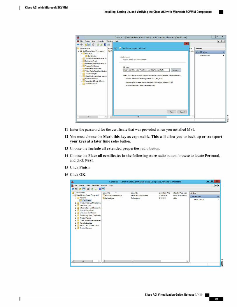
11 Enter the password for the certificate that was provided when you installed MSI.
12 You must choose theMark this key as exportable. This will allow you to back up or transportyour keys at a later time radio button.
13 Choose the Include all extended properties radio button.
14 Choose the Place all certificates in the following store radio button, browse to locate Personal,and click Next.
15 Click Finish.
16 Click OK.
Cisco ACI Virtualization Guide, Release 1.1(1j) 99
Cisco ACI with Microsoft SCVMMInstalling, Setting Up, and Verifying the Cisco ACI with Microsoft SCVMM Components
Step 6 Repeat steps 1 through 5 for each Hyper-V server.
Verifying the Installation of Cisco ACI with Microsoft SCVMM
Verifying the APIC SCVMM Agent Installation on SCVMM
This section describes how to verify the APIC SCVMM agent installation on System Center Virtual MachineManager (SCVMM).
Procedure
Step 1 Choose Start > Control Panel.Step 2 In the Control Panel window, enter Control Panel\Programs\Programs and Features in the address bar.Step 3 LocateCisco APIC SCVMMAgent. IfCisco APIC SCVMMAgent is present, then the product is installed.
If Cisco APIC SCVMM Agent is not present, then the product is not installed. See the Installing the APICSCVMM Agent on SCVMM, on page 93 or Installing the APIC Agent on SCVMM Using the WindowsCommand Prompt, on page 113 section.
Step 4 Verify the ApicVMMService is in RUNNING state through the GUI or CLI:
• GUI method: Choose Start > Run and enter services.msc. In the Service pane, locate theApicVMMService and verify the state is RUNNING.
• CLI method: From the command prompt, enter the sc.exe query ApicHypervAgent command andverify the state is RUNNING:sc query ApicVMMService
SERVICE_NAME: ApicVMMServiceTYPE : 10 WIN32_OWN_PROCESSSTATE : 4 RUNNING(STOPPABLE, NOT_PAUSABLE, ACCEPTS_SHUTDOWN)WIN32_EXIT_CODE : 0 (0x0)SERVICE_EXIT_CODE : 0 (0x0)CHECKPOINT : 0x0WAIT_HINT : 0x0
Verifying the APIC Hyper-V Agent Installation on the Hyper-V Server
This section describes how to verify the APIC Hyper-V agent installation on the Hyper-V server.
Cisco ACI Virtualization Guide, Release 1.1(1j)100
Cisco ACI with Microsoft SCVMMInstalling, Setting Up, and Verifying the Cisco ACI with Microsoft SCVMM Components
Procedure
Step 1 Choose Start > Control Panel.Step 2 In the Control Panel window, enter Control Panel\Programs\Programs and Features in the address bar.Step 3 Locate Cisco APIC Hyperv Agent. If Cisco APIC Hyperv Agent is present, then the product is installed.
If Cisco APIC Hyperv Agent is not present, then the product is not installed. See the Installing the APICHyper-V Agent on the Hyper-V Server, on page 97 or Installing the APIC Hyper-V Agent on the Hyper-VServer Using the Windows Command Prompt, on page 114 section.
Step 4 Verify the ApicHypervAgent is in RUNNING state through the GUI or CLI:
• GUI method: Choose Start > Run and enter services.msc. In the Service pane, locate theApicHypervAgent and verify the state is RUNNING.
• CLI method: From the command prompt, enter the sc.exe query ApicHypervAgent command andverify the state is RUNNING:sc.exe query ApicHypervAgent
SERVICE_NAME: ApicHypervAgentTYPE : 10 WIN32_OWN_PROCESSSTATE : 4 RUNNING(STOPPABLE, NOT_PAUSABLE, ACCEPTS_SHUTDOWN)WIN32_EXIT_CODE : 0 (0x0)SERVICE_EXIT_CODE : 0 (0x0)CHECKPOINT : 0x0WAIT_HINT : 0x0
Setting up ACI Policies
Creating SCVMM Domain Profiles
In this section, the examples of a VMM domain are System Center Virtual Machine Manager (SCVMM)domains. The example tasks are as follows:
• Configuring the VMM domain name and SCVMM controller.
• Creating an attach entity profile and associating it to the VMM domain.
• Configuring a pool.
• Verifying all configured controllers and their operational states.
Creating a SCVMM Domain Profile Using the GUI
Before You Begin
Before you create a VMM domain profile, you must establish connectivity to an external network usingin-band or out-of-band management network on the Application Policy Infrastructure Controller (APIC).
Cisco ACI Virtualization Guide, Release 1.1(1j) 101
Cisco ACI with Microsoft SCVMMInstalling, Setting Up, and Verifying the Cisco ACI with Microsoft SCVMM Components
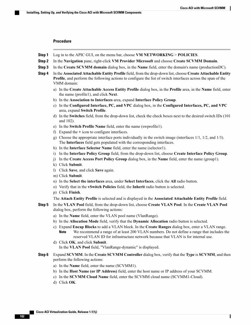
Procedure
Step 1 Log in to the APIC GUI, on the menu bar, choose VM NETWORKING > POLICIES.Step 2 In the Navigation pane, right-click VM Provider Microsoft and choose Create SCVMM Domain.Step 3 In the Create SCVMM domain dialog box, in the Name field, enter the domain's name (productionDC).Step 4 In theAssociated Attachable Entity Profile field, from the drop-down list, chooseCreate Attachable Entity
Profile, and perform the following actions to configure the list of switch interfaces across the span of theVMM domain:a) In the Create Attachable Access Entity Profile dialog box, in the Profile area, in the Name field, enter
the name (profile1), and click Next.b) In the Association to Interfaces area, expand Interface Policy Group.c) In the Configured Interface, PC, and VPC dialog box, in the Configured Interfaces, PC, and VPC
area, expand Switch Profile.d) In the Switches field, from the drop-down list, check the check boxes next to the desired switch IDs (101
and 102).e) In the Switch Profile Name field, enter the name (swprofile1).f) Expand the + icon to configure interfaces.g) Choose the appropriate interface ports individually in the switch image (interfaces 1/1, 1/2, and 1/3).
The Interfaces field gets populated with the corresponding interfaces.h) In the Interface Selector Name field, enter the name (selector1).i) In the Interface Policy Group field, from the drop-down list, choose Create Interface Policy Group.j) In the Create Access Port Policy Group dialog box, in the Name field, enter the name (group1).k) Click Submit.l) Click Save, and click Save again.m) Click Submit.n) In the Select the interfaces area, under Select Interfaces, click the All radio button.o) Verify that in the vSwitch Policies field, the Inherit radio button is selected.p) Click Finish.The Attach Entity Profile is selected and is displayed in the Associated Attachable Entity Profile field.
Step 5 In the VLAN Pool field, from the drop-down list, choose Create VLAN Pool. In the Create VLAN Pooldialog box, perform the following actions:a) In the Name field, enter the VLAN pool name (VlanRange).b) In the Allocation Mode field, verify that the Dynamic Allocation radio button is selected.c) Expand Encap Blocks to add a VLAN block. In the Create Ranges dialog box, enter a VLAN range.
We recommend a range of at least 200 VLAN numbers. Do not define a range that includes thereserved VLAN ID for infrastructure network because that VLAN is for internal use.
Note
d) Click OK, and click Submit.In the VLAN Pool field, "VlanRange-dynamic" is displayed.
Step 6 Expand SCVMM. In theCreate SCVMMController dialog box, verify that the Type is SCVMM, and thenperform the following actions:a) In the Name field, enter the name (SCVMM1).b) In the Host Name (or IP Address) field, enter the host name or IP address of your SCVMM.c) In the SCVMM Cloud Name field, enter the SCVMM cloud name (SCVMM1-Cloud).d) Click OK.
Cisco ACI Virtualization Guide, Release 1.1(1j)102
Cisco ACI with Microsoft SCVMMInstalling, Setting Up, and Verifying the Cisco ACI with Microsoft SCVMM Components
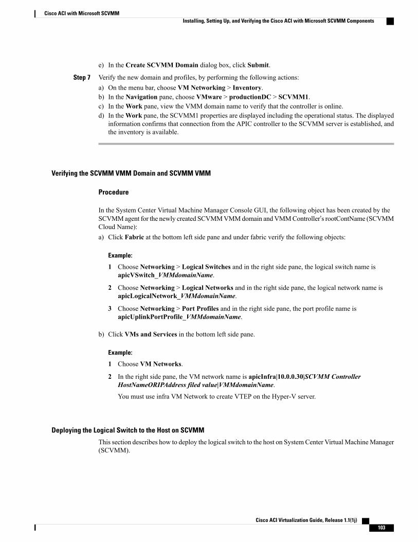
e) In the Create SCVMM Domain dialog box, click Submit.
Step 7 Verify the new domain and profiles, by performing the following actions:a) On the menu bar, choose VM Networking > Inventory.b) In the Navigation pane, choose VMware > productionDC > SCVMM1.c) In theWork pane, view the VMM domain name to verify that the controller is online.d) In theWork pane, the SCVMM1 properties are displayed including the operational status. The displayed
information confirms that connection from the APIC controller to the SCVMM server is established, andthe inventory is available.
Verifying the SCVMM VMM Domain and SCVMM VMM
Procedure
In the System Center Virtual Machine Manager Console GUI, the following object has been created by theSCVMMagent for the newly created SCVMMVMMdomain andVMMController’s rootContName (SCVMMCloud Name):a) Click Fabric at the bottom left side pane and under fabric verify the following objects:
Example:
1 Choose Networking > Logical Switches and in the right side pane, the logical switch name isapicVSwitch_VMMdomainName.
2 Choose Networking > Logical Networks and in the right side pane, the logical network name isapicLogicalNetwork_VMMdomainName.
3 Choose Networking > Port Profiles and in the right side pane, the port profile name isapicUplinkPortProfile_VMMdomainName.
b) Click VMs and Services in the bottom left side pane.
Example:
1 Choose VM Networks.
2 In the right side pane, the VM network name is apicInfra|10.0.0.30|SCVMM ControllerHostNameORIPAddress filed value|VMMdomainName.
You must use infra VM Network to create VTEP on the Hyper-V server.
Deploying the Logical Switch to the Host on SCVMM
This section describes how to deploy the logical switch to the host on System Center Virtual MachineManager(SCVMM).
Cisco ACI Virtualization Guide, Release 1.1(1j) 103
Cisco ACI with Microsoft SCVMMInstalling, Setting Up, and Verifying the Cisco ACI with Microsoft SCVMM Components
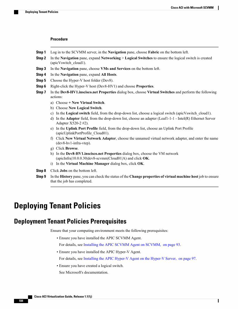
Procedure
Step 1 Log in to the SCVMM server, in the Navigation pane, choose Fabric on the bottom left.Step 2 In the Navigation pane, expand Networking > Logical Switches to ensure the logical switch is created
(apicVswitch_cloud1).Step 3 In the Navigation pane, choose VMs and Services on the bottom left.Step 4 In the Navigation pane, expand All Hosts.Step 5 Choose the Hyper-V host folder (Dev8).Step 6 Right-click the Hyper-V host (Dev8-HV1) and choose Properties.Step 7 In the Dev8-HV1.inscisco.net Properties dialog box, choose Virtual Switches and perform the following
actions:a) Choose + New Virtual Switch.b) Choose New Logical Switch.c) In the Logical switch field, from the drop-down list, choose a logical switch (apicVswitch_cloud1).d) In the Adapter field, from the drop-down list, choose an adapter (Leaf1-1-1 - Intel(R) Ethernet Server
Adapter X520-2 #2).e) In the Uplink Port Profile field, from the drop-down list, choose an Uplink Port Profile
(apicUplinkPortProfile_Cloud01).f) Click New Virtual Network Adapter, choose the unnamed virtual network adapter, and enter the name
(dev8-hv1-infra-vtep).g) Click Browse.h) In the Dev8-HV1.inscisco.net Properties dialog box, choose the VM network
(apicInfra|10.0.0.30|dev8-scvmm|Cloud01|A) and click OK.i) In the Virtual Machine Manager dialog box, click OK.
Step 8 Click Jobs on the bottom left.Step 9 In theHistory pane, you can check the status of theChange properties of virtual machine host job to ensure
that the job has completed.
Deploying Tenant Policies
Deployment Tenant Policies PrerequisitesEnsure that your computing environment meets the following prerequisites:
• Ensure you have installed the APIC SCVMM Agent.
For details, see Installing the APIC SCVMM Agent on SCVMM, on page 93.
• Ensure you have installed the APIC Hyper-V Agent.
For details, see Installing the APIC Hyper-V Agent on the Hyper-V Server, on page 97.
• Ensure you have created a logical switch.See Microsoft's documentation.
Cisco ACI Virtualization Guide, Release 1.1(1j)104
Cisco ACI with Microsoft SCVMMDeploying Tenant Policies
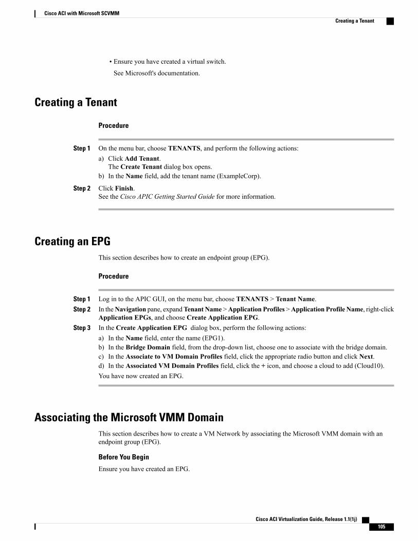
• Ensure you have created a virtual switch.See Microsoft's documentation.
Creating a Tenant
Procedure
Step 1 On the menu bar, choose TENANTS, and perform the following actions:a) Click Add Tenant.
The Create Tenant dialog box opens.b) In the Name field, add the tenant name (ExampleCorp).
Step 2 Click Finish.See the Cisco APIC Getting Started Guide for more information.
Creating an EPGThis section describes how to create an endpoint group (EPG).
Procedure
Step 1 Log in to the APIC GUI, on the menu bar, choose TENANTS > Tenant Name.Step 2 In theNavigation pane, expandTenant Name >Application Profiles >Application Profile Name, right-click
Application EPGs, and choose Create Application EPG.Step 3 In the Create Application EPG dialog box, perform the following actions:
a) In the Name field, enter the name (EPG1).b) In the Bridge Domain field, from the drop-down list, choose one to associate with the bridge domain.c) In the Associate to VM Domain Profiles field, click the appropriate radio button and click Next.d) In the Associated VM Domain Profiles field, click the + icon, and choose a cloud to add (Cloud10).You have now created an EPG.
Associating the Microsoft VMM DomainThis section describes how to create a VM Network by associating the Microsoft VMM domain with anendpoint group (EPG).
Before You Begin
Ensure you have created an EPG.
Cisco ACI Virtualization Guide, Release 1.1(1j) 105
Cisco ACI with Microsoft SCVMMCreating a Tenant
Procedure
Step 1 Log in to the APIC GUI, on the menu bar, choose TENANTS > Tenant Name.Step 2 In the Navigation pane, expand Tenant Name > Application Profiles > Application Profile Name >
Application EPGs and select an existing EPG.Step 3 In the Navigation pane, choose Domains (VMs and Bare-Metals).Step 4 In the Domains (VM and Bare-Metals) pane, click on the ACTIONS and choose Add VMM Domain
Association.Step 5 In theAdd VMMDomain Association dialog box, click theDeploy Immediacy field radio button for either
Immediate or On Demand.See EPG Policy Resolution and Deployment Immediacy, on page 8 for more information.
Step 6 In the Add VMM Domain Association dialog box, click the Resolution Immediacy field radio button foreither On Demand, or Pre-Provision.
“Resolution == Immediate” is not supported in this release.Note
See EPG Policy Resolution and Deployment Immediacy, on page 8 for more information.
You have now created a VM Network.
Verifying the EPG is Associated with the VMM Domain on APICThis section describes how to verify the endpoint group association with the VMM domain on ApplicationPolicy Infrastructure Controller (APIC).
Procedure
Step 1 Log in to the APIC GUI, on the menu bar, choose VM NETWORKING > INVENTORY.Step 2 In the Navigation pane, expandMicrosoft > Cloud10 > Controller > Controller1 > Distributed Virtual
Switch > SCVMM|Tenant|SCVMM|EPG1|Cloud1.The name of the new VM Network is in the following format: Tenant Name|Application ProfileName|Application EPG Name|Microsoft VMM Domain.
Step 3 In the PROPERTIES pane, verify the EPG associated with the VMM domain, the VM Network, and thedetails such as NIC NAME, VM NAME, IP, MAC, and STATE.
Verifying the EPG is Associated with the VMM Domain on SCVMMThis section describes how to verify the endpoint group (EPG) associated with the VMM domain on SystemCenter Virtual Machine Manager (SCVMM).
Cisco ACI Virtualization Guide, Release 1.1(1j)106
Cisco ACI with Microsoft SCVMMVerifying the EPG is Associated with the VMM Domain on APIC
Procedure
Step 1 Open the Virual Machine Manager Console icon on your desktop.Step 2 In the bottom left pane, click on VMs and Services or press Ctrl+M.Step 3 In theVMs and Services pane, click onVMNetworks and verify the EPG associated with the VMMdomain.
The EPG associated with the VMM domain is in the following format: Tenant Name|Application ProfileName|Application EPG Name|Microsoft VMM Domain.
Connecting and Powering on the Virtual MachineThis section describes how to connect and power on the virtual machine.
Procedure
Step 1 Log in to the SCVMM server, choose VMs and Services > All Hosts, and choose one of the hosts.Step 2 In the VMs pane, right-click on the VM host that you want to associate to the VM Network and choose
Properties.Step 3 In the Properties dialog box, choose Hardware Configuration, and choose a network adapter (Network
Adapter 1).Step 4 In the Network Adapter 1 pane, perform the following actions to connect to a VM network:
a) Click the Connect to a VM network radio button.b) Click the Browse button.c) Verify the list of VM networks, which lists all of the VM networks to which the hypervisor is associated.
Step 5 Power on the virtual machine.
Verifying the Association on APICThis section describes how to verify the association on Application Policy Infrastructure Controller (APIC).
Procedure
Step 1 Log in to the APIC GUI, on the menu bar, choose VM NETWORKING > INVENTORY.Step 2 In the Navigation pane, expandMicrosoft > Cloud10 > Controller > Controller1 > Hypervisors >
Hypervisor1 > Virtual Machines to verify the association.
Cisco ACI Virtualization Guide, Release 1.1(1j) 107
Cisco ACI with Microsoft SCVMMConnecting and Powering on the Virtual Machine
Viewing EPGs on APICThis section describes how to view endpoint groups (EPGs) on the Application Policy Infrastructure Controller(APIC).
Procedure
Step 1 Log in to the APIC GUI, on the menu bar, choose TENANTS > Tenant Name.Step 2 In the Navigation pane, expand Tenant Name > Application Profiles > VMM > Application EPGs >
EPG1.Step 3 In the Application EPG - EPG1 pane, click the OPERATIONAL button, and verify if the endpoint group
is present.
Troubleshooting the Cisco ACI with Microsoft SCVMM
Troubleshooting APIC to SCVMM ConnectivityUse the ApicVMMService logs to debug the System Center Virtual Machine Manager (SCVMM) server.
Procedure
Step 1 Log in to the SCVMM server, go to the ApicVMMService logs. Located at C:\Program Files(X86)\ApicVMMService\Logs.
Step 2 Check the ApicVMMService logs to debug.If you are unable to debug, on the SCVMM server copy all the ApicVMMService logs from C:\ProgramFiles (X86)\ApicVMMService\Logs and send them to Cisco Tech Support.
Troubleshooting APIC to Hyper-V Host ConnectivityUse the ApicHypervAgent logs to debug the Hyper-V servers.
Procedure
Step 1 Log in to the Hyper-V servers, go to the ApicHypervAgent logs. Located at C:\Program Files(x86)\ApicHypervAgent\Logs.
Step 2 Check the ApicHypervAgent logs to debug.If you are unable to debug, on the Hyper-V servers copy all the ApicHypervAgent logs from C:\ProgramFiles (x86)\ApicHypervAgent\Logs and send them to Cisco Tech Support.
Cisco ACI Virtualization Guide, Release 1.1(1j)108
Cisco ACI with Microsoft SCVMMViewing EPGs on APIC
Troubleshooting the EPG Configuration IssueIf during the lifetime of the endpoint group (EPG), the VLAN ID of the EPG changes on the APIC, thenSCVMM needs to update the VLAN configuration on all virtual machines for the new setting to take effect.
Procedure
To perform this operation run the following PowerShell commands on the SCVMM server:
Example:$VMs = Get-SCVirtualMachine$VMs | Read-SCVirtualMachine$NonCompliantAdapters=Get-SCVirtualNetworkAdapter -All | Where-Object{$_.VirtualNetworkAdapterComplianceStatus -eq "NonCompliant"}$NonCompliantAdapters | Repair-SCVirtualNetworkAdapter
REST API References
Creating a SCVMM Domain Profile Using the REST APIThis section describes how to create a SCVMM domain profile using the REST API.
Procedure
Step 1 Configure a VMM domain name and System Center Virtual Machine Manager (SCVMM) Controller.
Example:https://<apic-ip>/api/node/mo/.xml
<polUni><vmmProvP vendor="Microsoft"><!-- VMM Domain --><vmmDomP name="productionDC"><!-- Association to VLAN Namespace --><infraRsVlanNs tDn="uni/infra/vlanns-VlanRange-dynamic"/><!-- SCVMM IP address information<vmmCtrlrP name="SCVMM1" hostOrIp="172.21.120.21" rootContName="rootCont01"> --></vmmCtrlrP></vmmDomP></vmmProvP>
Step 2 Create an attachable entity profile for VLAN namespace deployment.
Example:https://<apic-ip>/api/policymgr/mo/uni.xml<infraInfra><infraAttEntityP name="profile1"><infraRsDomP tDn="uni/vmmp-Microsoft/dom-productionDC"/>
Cisco ACI Virtualization Guide, Release 1.1(1j) 109
Cisco ACI with Microsoft SCVMMTroubleshooting the EPG Configuration Issue
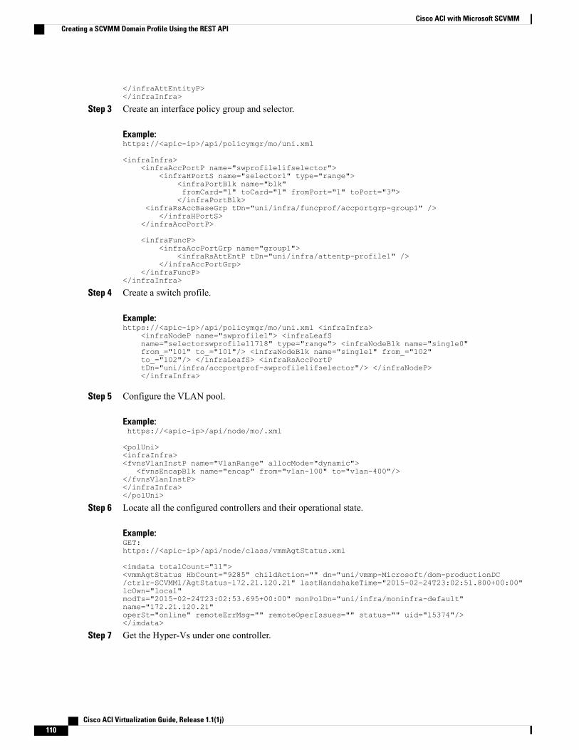
</infraAttEntityP></infraInfra>
Step 3 Create an interface policy group and selector.
Example:https://<apic-ip>/api/policymgr/mo/uni.xml
<infraInfra><infraAccPortP name="swprofile1ifselector">
<infraHPortS name="selector1" type="range"><infraPortBlk name="blk"fromCard="1" toCard="1" fromPort="1" toPort="3"></infraPortBlk>
<infraRsAccBaseGrp tDn="uni/infra/funcprof/accportgrp-group1" /></infraHPortS>
</infraAccPortP>
<infraFuncP><infraAccPortGrp name="group1">
<infraRsAttEntP tDn="uni/infra/attentp-profile1" /></infraAccPortGrp>
</infraFuncP></infraInfra>
Step 4 Create a switch profile.
Example:https://<apic-ip>/api/policymgr/mo/uni.xml <infraInfra>
<infraNodeP name="swprofile1"> <infraLeafSname="selectorswprofile11718" type="range"> <infraNodeBlk name="single0"from_="101" to_="101"/> <infraNodeBlk name="single1" from_="102"to_="102"/> </infraLeafS> <infraRsAccPortPtDn="uni/infra/accportprof-swprofile1ifselector"/> </infraNodeP></infraInfra>
Step 5 Configure the VLAN pool.
Example:https://<apic-ip>/api/node/mo/.xml
<polUni><infraInfra><fvnsVlanInstP name="VlanRange" allocMode="dynamic">
<fvnsEncapBlk name="encap" from="vlan-100" to="vlan-400"/></fvnsVlanInstP></infraInfra></polUni>
Step 6 Locate all the configured controllers and their operational state.
Example:GET:https://<apic-ip>/api/node/class/vmmAgtStatus.xml
<imdata totalCount="11"><vmmAgtStatus HbCount="9285" childAction="" dn="uni/vmmp-Microsoft/dom-productionDC/ctrlr-SCVMM1/AgtStatus-172.21.120.21" lastHandshakeTime="2015-02-24T23:02:51.800+00:00"lcOwn="local"modTs="2015-02-24T23:02:53.695+00:00" monPolDn="uni/infra/moninfra-default"name="172.21.120.21"operSt="online" remoteErrMsg="" remoteOperIssues="" status="" uid="15374"/></imdata>
Step 7 Get the Hyper-Vs under one controller.
Cisco ACI Virtualization Guide, Release 1.1(1j)110
Cisco ACI with Microsoft SCVMMCreating a SCVMM Domain Profile Using the REST API

Example:
https://<apic-ip>/api/node/class/opflexODev.json?query-target-filter=and(eq(opflexODev.ctrlrName,'Scale-Scvmm1.inscisco.net'),eq(opflexODev.domName,'Domain1'),ne(opflexODev.isSecondary,'true'))
{"totalCount":"8","subscriptionId":"72057718609018900","imdata":[{"opflexODev":{"attributes":{"childAction":"","ctrlrName":"Scale-Scvmm1.inscisco.net","devId":"167807069","devOperIssues":"","devType":"hyperv","dn":"topology/pod-1/node-191/sys/br-[eth1/43]/odev-167807069","domName":"Domain1","encap":"unknown","features":"0","hbStatus":"valid-dvs","hostName":"Scale-Hv2.inscisco.net","id":"0","ip":"0.0.0.0","ipAddr":"10.0.136.93","isSecondary":"false","lNodeDn":"","lastHandshakeTime":"2015-04-15T17:10:25.684-07:00","lastNumHB":"19772","lcOwn":"local","mac":"00:00:00:00:00:00","maxMissHb":"0","modTs":"2015-04-15T17:12:09.485-07:00","monPolDn":"uni/fabric/monfab-default","name":"","numHB":"19772","operSt":"identified","pcIfId":"1","portId":"0","state":"connected","status":"","transitionStatus":"attached","uid":"15374","updateTs":"0","uuid":"","version":""}}},{"opflexODev":{"attributes":{"childAction":"","ctrlrName":"Scale-Scvmm1.inscisco.net","devId":"167831641","devOperIssues":"","devType":"hyperv","dn":"topology/pod-1/node-191/sys/br-[eth1/43]/odev-167831641","domName":"Domain1","encap":"unknown","features":"0","hbStatus":"valid-dvs","hostName":"Scale-Hv6.inscisco.net","id":"0","ip":"0.0.0.0","ipAddr":"10.0.232.89","isSecondary":"false","lNodeDn":"","lastHandshakeTime":"2015-04-15T17:10:26.492-07:00","lastNumHB":"15544","lcOwn":"local","mac":"00:00:00:00:00:00","maxMissHb":"0","modTs":"2015-04-15T17:12:10.292-07:00","monPolDn":"uni/fabric/monfab-default","name":"","numHB":"15544","operSt":"identified","pcIfId":"1","portId":"0","state":"connected","status":"","transitionStatus":"attached","uid":"15374","updateTs":"0","uuid":"","version":""}}},{"opflexODev":{"attributes":{"childAction":"","ctrlrName":"Scale-Scvmm1.inscisco.net","devId":"167831643","devOperIssues":"","devType":"hyperv","dn":"topology/pod-1/node-191/sys/br-[eth1/43]/odev-167831643","domName":"Domain1","encap":"unknown","features":"0","hbStatus":"valid-dvs","hostName":"Scale-Hv3.inscisco.net","id":"0","ip":"0.0.0.0","ipAddr":"10.0.232.91","isSecondary":"false","lNodeDn":"","lastHandshakeTime":"2015-04-15T17:10:23.268-07:00","lastNumHB":"15982","lcOwn":"local","mac":"00:00:00:00:00:00","maxMissHb":"0","modTs":"2015-04-15T17:12:07.068-07:00","monPolDn":"uni/fabric/monfab-default","name":"","numHB":"15982","operSt":"identified","pcIfId":"1","portId":"0","state":"connected","status":"","transitionStatus":"attached","uid":"15374","updateTs":"0","uuid":"","version":""}}},{"opflexODev":{"attributes":{"childAction":"","ctrlrName":"Scale-Scvmm1.inscisco.net","devId":"167807070","devOperIssues":"","devType":"hyperv","dn":"topology/pod-1/node-191/sys/br-[eth1/43]/odev-167807070","domName":"Domain1","encap":"unknown","features":"0","hbStatus":"valid-dvs","hostName":"Scale-Hv8.inscisco.net","id":"0","ip":"0.0.0.0","ipAddr":"10.0.136.94","isSecondary":"false","lNodeDn":"","lastHandshakeTime":"2015-04-15T17:10:26.563-07:00","lastNumHB":"14219","lcOwn":"local","mac":"00:00:00:00:00:00","maxMissHb":"0","modTs":"2015-04-15T17:12:10.364-07:00","monPolDn":"uni/fabric/monfab-default","name":"","numHB":"14219","operSt":"identified","pcIfId":"1","portId":"0","state":"connected","status":"","transitionStatus":"attached","uid":"15374","updateTs":"0","uuid":"","version":""}}},{"opflexODev":{"attributes":{"childAction":"","ctrlrName":"Scale-Scvmm1.inscisco.net","devId":"167831642","devOperIssues":"","devType":"hyperv","dn":"topology/pod-1/node-191/sys/br-[eth1/43]/odev-167831642","domName":"Domain1","encap":"unknown","features":"0","hbStatus":"valid-dvs","hostName":"Scale-Hv4.inscisco.net","id":"0","ip":"0.0.0.0","ipAddr":"10.0.232.90","isSecondary":"false","lNodeDn":"","lastHandshakeTime":"2015-04-15T17:10:24.978-07:00","lastNumHB":"13947","lcOwn":"local","mac":"00:00:00:00:00:00","maxMissHb":"0","modTs":"2015-04-15T17:12:08.778-07:00","monPolDn":"uni/fabric/monfab-default","name":"","numHB":"13947","operSt":"identified","pcIfId":"1","portId":"0","state":"connected","status":"","transitionStatus":"attached","uid":"15374","updateTs":"0","uuid":"","version":""}}},{"opflexODev":{"attributes":{"childAction":"","ctrlrName":"Scale-Scvmm1.inscisco.net","devId":"167807071","devOperIssues":"","devType":"hyperv","dn":"topology/pod-1/node-190/sys/br-[eth1/43]/odev-167807071","domName":"Domain1","encap":"unknown","features":"0","hbStatus":"valid-dvs","hostName":"Scale-Hv7.inscisco.net","id":"0","ip":"0.0.0.0","ipAddr":"10.0.136.95","isSecondary":"false","lNodeDn":"","lastHandshakeTime":"2015-04-15T17:12:10.057-07:00","lastNumHB":"5708","lcOwn":"local","mac":"00:00:00:00:00:00","maxMissHb":"0","modTs":"2015-04-15T17:12:09.659-07:00","monPolDn":"uni/fabric/monfab-default","name":"","numHB":"5708","operSt":"identified","pcIfId":"1","portId":"0","state":"connected","status":"","transitionStatus":"attached","uid":"15374","updateTs":"0","uuid":"","version":""}}},{"opflexODev":{"attributes":{"childAction":"","ctrlrName":"Scale-Scvmm1.inscisco.net","devId":"167807067","devOperIssues":"","devType":"hyperv","dn":"topology/pod-1/node-190/sys/br-[eth1/43]/odev-167807067","domName":"Domain1","encap":"unknown","features":"0","hbStatus":"valid-dvs","hostName":"Scale-Hv1.inscisco.net","id":"0","ip":"0.0.0.0","ipAddr":"10.0.136.91","isSecondary":"false","lNodeDn":"","lastHandshakeTime":"2015-04-15T17:12:08.637-07:00","lastNumHB":"17659","lcOwn":"local","mac":"00:00:00:00:00:00","maxMissHb":"0","modTs":"2015-04-15T17:12:08.240-07:00","monPolDn":"uni/fabric/monfab-default","name":"","numHB":"17659","operSt":"identified","pcIfId":"1","portId":"0","state":"connected","status":"","transitionStatus":"attached","uid":"15374","updateTs":"0","uuid":"","version":""}}},{"opflexODev":{"attributes":{"childAction":"","ctrlrName":"Scale-Scvmm1.inscisco.net","devId":"167831644","devOperIssues":"","devType":"hyperv","dn":"topology/pod-1/node-190/sys/br-[eth1/43]/odev-167831644","domName":"Domain1","encap":"unknown","features":"0","hbStatus":"valid-dvs","hostName":"Scale-Hv5.inscisco.net","id":"0","ip":"0.0.0.0","ipAddr":"10.0.232.92","isSecondary":"false","lNodeDn":"","lastHandshakeTime":"2015-04-15T17:12:09.093-07:00","lastNumHB":"15433","lcOwn":"local","mac":"00:00:00:00:00:00","maxMissHb":"0","modTs":"2015-04-15T17:12:08.695-07:00","monPolDn":"uni/fabric/monfab-default","name":"","numHB":"15433","operSt":"identified","pcIfId":"1","portId":"0","state":"connected","status":"","transitionStatus":"attached","uid":"15374","updateTs":"0","uuid":"","version":""}}}]}
Step 8 Get the VMs under one Hyper-V.
Cisco ACI Virtualization Guide, Release 1.1(1j) 111
Cisco ACI with Microsoft SCVMMCreating a SCVMM Domain Profile Using the REST API

Example:
https://<apic-ip>/api/node/mo/topology/pod-1/node-190/sys/br-[eth1/43]/odev-167807067.json?query-target=children&target-subtree-class=opflexOVm&subscription=yes
{"totalCount":"1","subscriptionId":"72057718609018947","imdata":[{"opflexOVm":{"attributes":{"childAction":"","ctrlrName":"Scale-Scvmm1.inscisco.net","dn":"topology/pod-1/node-190/sys/br-[eth1/43]/odev-167807067/ovm-ExtConn_1002_EPG17_003","domName":"Domain1","id":"0","lcOwn":"local","modTs":"2015-04-14T17:36:51.512-07:00","name":"ExtConn_1002_EPG17_003","state":"Powered On","status":"","uid":"15374"}}}]}
Step 9 Get VNICs under one VM.
Example:
https://<apic-ip>/api/node/class/opflexIDEp.json?query-target-filter=eq(opflexIDEp.containerName,'ExtConn_1002_EPG17_003')
{"totalCount":"4","subscriptionId":"72057718609018983","imdata":[{"opflexIDEp":{"attributes":{"brIfId":"eth1/43","childAction":"","compHvDn":"","compVmDn":"","containerName":"ExtConn_1002_EPG17_003","ctrlrName":"Scale-Scvmm1.inscisco.net","dn":"topology/pod-1/node-190/sys/br-[eth1/43]/idep-00:15:5D:D2:14:84-encap-[vlan-1398]","domName":"Domain1","domPDn":"","dpAttr":"0","encap":"vlan-1398","epHostAddr":"http://10.0.136.91:17000/Vleaf/policies/setpolicies","epPolDownloadHint":"all","epgID":"","eppDownloadHint":"always","eppdn":"uni/epp/fv-[uni/tn-ExtConn_1002/ap-SCVMM/epg-EPG17]","gtag":"0","handle":"0","hypervisorName":"Scale-Hv1.inscisco.net","id":"0","instType":"unknown","ip":"0.0.0.0","lcC":"","lcOwn":"local","mac":"00:15:5D:D2:14:84","mcastAddr":"0.0.0.0","modTs":"2015-04-14T17:36:50.838-07:00","monPolDn":"uni/fabric/monfab-default","name":"00155DD21484","pcIfId":"1","portId":"0","scopeId":"0","state":"up","status":"","transitionStatus":"attached","uuid":"","vendorId":"Microsoft","vmAttr":"vm-name","vmAttrDn":"","vmAttrOp":"equals","vmAttrOverride":"0","vmmSrc":"msft"}}},{"opflexIDEp":{"attributes":{"brIfId":"eth1/43","childAction":"","compHvDn":"","compVmDn":"","containerName":"ExtConn_1002_EPG17_003","ctrlrName":"Scale-Scvmm1.inscisco.net","dn":"topology/pod-1/node-190/sys/br-[eth1/43]/idep-00:15:5D:D2:14:85-encap-[vlan-1438]","domName":"Domain1","domPDn":"","dpAttr":"0","encap":"vlan-1438","epHostAddr":"http://10.0.136.91:17000/Vleaf/policies/setpolicies","epPolDownloadHint":"all","epgID":"","eppDownloadHint":"always","eppdn":"uni/epp/fv-[uni/tn-ExtConn_1002/ap-SCVMM-Domain1/epg-EPG1]","gtag":"0","handle":"0","hypervisorName":"Scale-Hv1.inscisco.net","id":"0","instType":"unknown","ip":"0.0.0.0","lcC":"","lcOwn":"local","mac":"00:15:5D:D2:14:85","mcastAddr":"0.0.0.0","modTs":"2015-04-14T17:36:51.025-07:00","monPolDn":"uni/fabric/monfab-default","name":"00155DD21485","pcIfId":"1","portId":"0","scopeId":"0","state":"up","status":"","transitionStatus":"attached","uuid":"","vendorId":"Microsoft","vmAttr":"vm-name","vmAttrDn":"","vmAttrOp":"equals","vmAttrOverride":"0","vmmSrc":"msft"}}},{"opflexIDEp":{"attributes":{"brIfId":"eth1/43","childAction":"","compHvDn":"","compVmDn":"","containerName":"ExtConn_1002_EPG17_003","ctrlrName":"Scale-Scvmm1.inscisco.net","dn":"topology/pod-1/node-191/sys/br-[eth1/43]/idep-00:15:5D:D2:14:84-encap-[vlan-1398]","domName":"Domain1","domPDn":"","dpAttr":"0","encap":"vlan-1398","epHostAddr":"http://10.0.136.91:17000/Vleaf/policies/setpolicies","epPolDownloadHint":"all","epgID":"","eppDownloadHint":"always","eppdn":"uni/epp/fv-[uni/tn-ExtConn_1002/ap-SCVMM/epg-EPG17]","gtag":"0","handle":"0","hypervisorName":"Scale-Hv1.inscisco.net","id":"0","instType":"unknown","ip":"0.0.0.0","lcC":"","lcOwn":"local","mac":"00:15:5D:D2:14:84","mcastAddr":"0.0.0.0","modTs":"2015-04-14T17:36:50.731-07:00","monPolDn":"uni/fabric/monfab-default","name":"00155DD21484","pcIfId":"1","portId":"0","scopeId":"0","state":"up","status":"","transitionStatus":"attached","uuid":"","vendorId":"Microsoft","vmAttr":"vm-name","vmAttrDn":"","vmAttrOp":"equals","vmAttrOverride":"0","vmmSrc":"msft"}}},{"opflexIDEp":{"attributes":{"brIfId":"eth1/43","childAction":"","compHvDn":"","compVmDn":"","containerName":"ExtConn_1002_EPG17_003","ctrlrName":"Scale-Scvmm1.inscisco.net","dn":"topology/pod-1/node-191/sys/br-[eth1/43]/idep-00:15:5D:D2:14:85-encap-[vlan-1438]","domName":"Domain1","domPDn":"","dpAttr":"0","encap":"vlan-1438","epHostAddr":"http://10.0.136.91:17000/Vleaf/policies/setpolicies","epPolDownloadHint":"all","epgID":"","eppDownloadHint":"always","eppdn":"uni/epp/fv-[uni/tn-ExtConn_1002/ap-SCVMM-Domain1/epg-EPG1]","gtag":"0","handle":"0","hypervisorName":"Scale-Hv1.inscisco.net","id":"0","instType":"unknown","ip":"0.0.0.0","lcC":"","lcOwn":"local","mac":"00:15:5D:D2:14:85","mcastAddr":"0.0.0.0","modTs":"2015-04-14T17:36:50.932-07:00","monPolDn":"uni/fabric/monfab-default","name":"00155DD21485","pcIfId":"1","portId":"0","scopeId":"0","state":"up","status":"","transitionStatus":"attached","uuid":"","vendorId":"Microsoft","vmAttr":"vm-name","vmAttrDn":"","vmAttrOp":"equals","vmAttrOverride":"0","vmmSrc":"msft"}}}]}
Displaying the Certificate Information to be Used on APIC Using the REST APIThis section describes how to display the certificate information to be used on APIC using the REST API.
Cisco ACI Virtualization Guide, Release 1.1(1j)112
Cisco ACI with Microsoft SCVMMDisplaying the Certificate Information to be Used on APIC Using the REST API
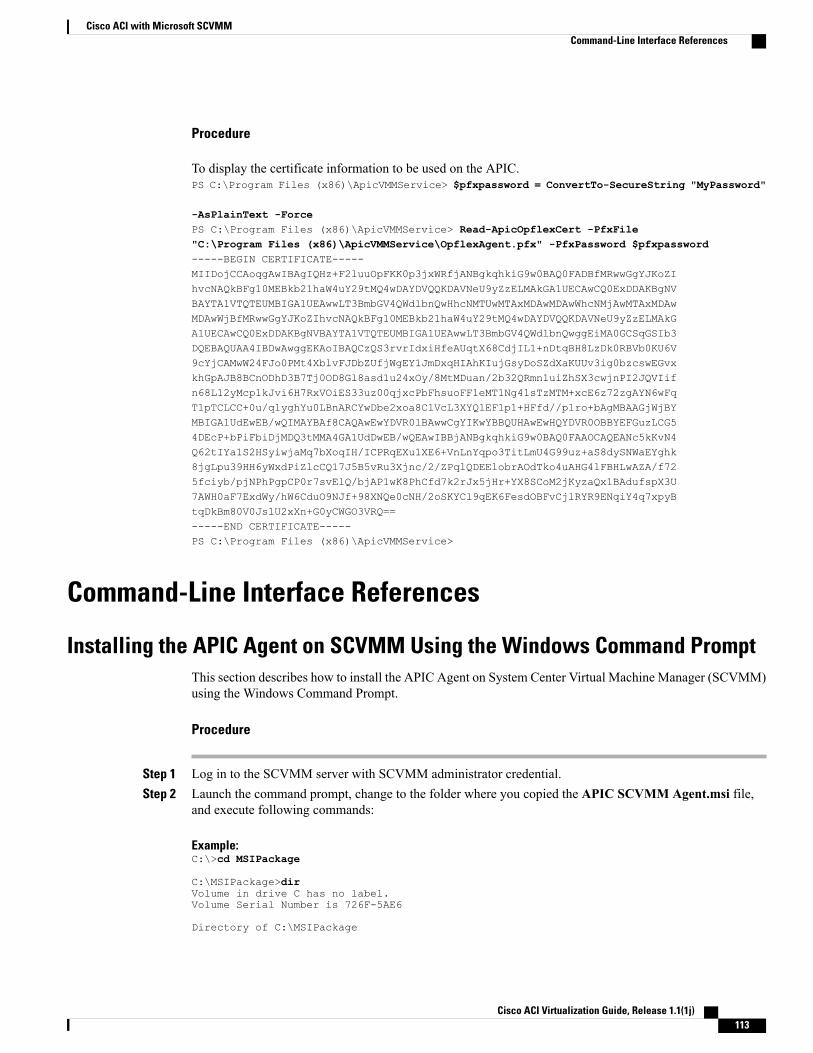
Procedure
To display the certificate information to be used on the APIC.PS C:\Program Files (x86)\ApicVMMService> $pfxpassword = ConvertTo-SecureString "MyPassword"
-AsPlainText -ForcePS C:\Program Files (x86)\ApicVMMService> Read-ApicOpflexCert -PfxFile"C:\Program Files (x86)\ApicVMMService\OpflexAgent.pfx" -PfxPassword $pfxpassword-----BEGIN CERTIFICATE-----MIIDojCCAoqgAwIBAgIQHz+F2luuOpFKK0p3jxWRfjANBgkqhkiG9w0BAQ0FADBfMRwwGgYJKoZIhvcNAQkBFg10MEBkb21haW4uY29tMQ4wDAYDVQQKDAVNeU9yZzELMAkGA1UECAwCQ0ExDDAKBgNVBAYTA1VTQTEUMBIGA1UEAwwLT3BmbGV4QWdlbnQwHhcNMTUwMTAxMDAwMDAwWhcNMjAwMTAxMDAwMDAwWjBfMRwwGgYJKoZIhvcNAQkBFg10MEBkb21haW4uY29tMQ4wDAYDVQQKDAVNeU9yZzELMAkGA1UECAwCQ0ExDDAKBgNVBAYTA1VTQTEUMBIGA1UEAwwLT3BmbGV4QWdlbnQwggEiMA0GCSqGSIb3DQEBAQUAA4IBDwAwggEKAoIBAQCzQS3rvrIdxiHfeAUqtX68CdjIL1+nDtqBH8LzDk0RBVb0KU6V9cYjCAMwW24FJo0PMt4XblvFJDbZUfjWgEY1JmDxqHIAhKIujGsyDoSZdXaKUUv3ig0bzcswEGvxkhGpAJB8BCnODhD3B7Tj0OD8Gl8asd1u24xOy/8MtMDuan/2b32QRmn1uiZhSX3cwjnPI2JQVIifn68L12yMcp1kJvi6H7RxVOiES33uz00qjxcPbFhsuoFF1eMT1Ng41sTzMTM+xcE6z72zgAYN6wFqT1pTCLCC+0u/q1yghYu0LBnARCYwDbe2xoa8ClVcL3XYQlEFlp1+HFfd//p1ro+bAgMBAAGjWjBYMBIGA1UdEwEB/wQIMAYBAf8CAQAwEwYDVR0lBAwwCgYIKwYBBQUHAwEwHQYDVR0OBBYEFGuzLCG54DEcP+bPiFbiDjMDQ3tMMA4GA1UdDwEB/wQEAwIBBjANBgkqhkiG9w0BAQ0FAAOCAQEANc5kKvN4Q62tIYa1S2HSyiwjaMq7bXoqIH/ICPRqEXu1XE6+VnLnYqpo3TitLmU4G99uz+aS8dySNWaEYghk8jgLpu39HH6yWxdPiZlcCQ17J5B5vRu3Xjnc/2/ZPqlQDEElobrAOdTko4uAHG4lFBHLwAZA/f725fciyb/pjNPhPgpCP0r7svElQ/bjAP1wK8PhCfd7k2rJx5jHr+YX8SCoM2jKyzaQx1BAdufspX3U7AWH0aF7ExdWy/hW6CduO9NJf+98XNQe0cNH/2oSKYCl9qEK6FesdOBFvCjlRYR9ENqiY4q7xpyBtqDkBm80V0JslU2xXn+G0yCWGO3VRQ==-----END CERTIFICATE-----PS C:\Program Files (x86)\ApicVMMService>
Command-Line Interface References
Installing the APIC Agent on SCVMM Using the Windows Command PromptThis section describes how to install the APIC Agent on System Center Virtual Machine Manager (SCVMM)using the Windows Command Prompt.
Procedure
Step 1 Log in to the SCVMM server with SCVMM administrator credential.Step 2 Launch the command prompt, change to the folder where you copied the APIC SCVMM Agent.msi file,
and execute following commands:
Example:C:\>cd MSIPackage
C:\MSIPackage>dirVolume in drive C has no label.Volume Serial Number is 726F-5AE6
Directory of C:\MSIPackage
Cisco ACI Virtualization Guide, Release 1.1(1j) 113
Cisco ACI with Microsoft SCVMMCommand-Line Interface References
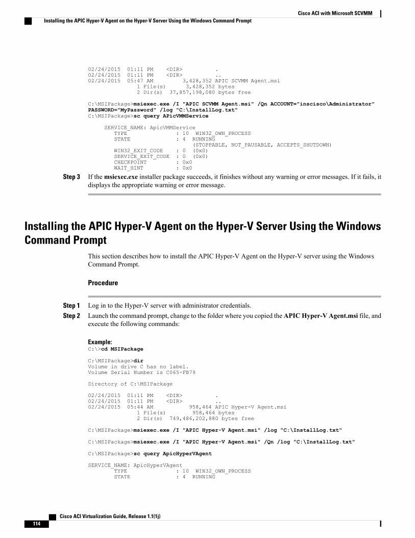
02/24/2015 01:11 PM <DIR> .02/24/2015 01:11 PM <DIR> ..02/24/2015 05:47 AM 3,428,352 APIC SCVMM Agent.msi
1 File(s) 3,428,352 bytes2 Dir(s) 37,857,198,080 bytes free
C:\MSIPackage>msiexec.exe /I "APIC SCVMM Agent.msi" /Qn ACCOUNT="inscisco\Administrator"PASSWORD="MyPassword" /log "C:\InstallLog.txt"C:\MSIPackage>sc query APicVMMService
SERVICE_NAME: ApicVMMServiceTYPE : 10 WIN32_OWN_PROCESSSTATE : 4 RUNNING
(STOPPABLE, NOT_PAUSABLE, ACCEPTS_SHUTDOWN)WIN32_EXIT_CODE : 0 (0x0)SERVICE_EXIT_CODE : 0 (0x0)CHECKPOINT : 0x0WAIT_HINT : 0x0
Step 3 If themsiexec.exe installer package succeeds, it finishes without any warning or error messages. If it fails, itdisplays the appropriate warning or error message.
Installing the APIC Hyper-V Agent on the Hyper-V Server Using the WindowsCommand Prompt
This section describes how to install the APIC Hyper-V Agent on the Hyper-V server using the WindowsCommand Prompt.
Procedure
Step 1 Log in to the Hyper-V server with administrator credentials.Step 2 Launch the command prompt, change to the folder where you copied theAPICHyper-V Agent.msi file, and
execute the following commands:
Example:C:\>cd MSIPackage
C:\MSIPackage>dirVolume in drive C has no label.Volume Serial Number is C065-FB79
Directory of C:\MSIPackage
02/24/2015 01:11 PM <DIR> .02/24/2015 01:11 PM <DIR> ..02/24/2015 05:44 AM 958,464 APIC Hyper-V Agent.msi
1 File(s) 958,464 bytes2 Dir(s) 749,486,202,880 bytes free
C:\MSIPackage>msiexec.exe /I "APIC Hyper-V Agent.msi" /log "C:\InstallLog.txt"
C:\MSIPackage>msiexec.exe /I "APIC Hyper-V Agent.msi" /Qn /log "C:\InstallLog.txt"
C:\MSIPackage>sc query ApicHyperVAgent
SERVICE_NAME: ApicHyperVAgentTYPE : 10 WIN32_OWN_PROCESSSTATE : 4 RUNNING
Cisco ACI Virtualization Guide, Release 1.1(1j)114
Cisco ACI with Microsoft SCVMMInstalling the APIC Hyper-V Agent on the Hyper-V Server Using the Windows Command Prompt
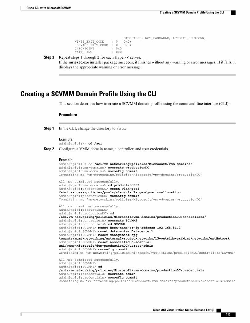
(STOPPABLE, NOT_PAUSABLE, ACCEPTS_SHUTDOWN)WIN32_EXIT_CODE : 0 (0x0)SERVICE_EXIT_CODE : 0 (0x0)CHECKPOINT : 0x0WAIT_HINT : 0x0
Step 3 Repeat steps 1 through 2 for each Hyper-V server.If themsiexec.exe installer package succeeds, it finishes without any warning or error messages. If it fails, itdisplays the appropriate warning or error message.
Creating a SCVMM Domain Profile Using the CLIThis section describes how to create a SCVMM domain profile using the command-line interface (CLI).
Procedure
Step 1 In the CLI, change the directory to /aci.
Example:admin@apic1:~> cd /aci
Step 2 Configure a VMM domain name, a controller, and user credentials.
Example:admin@apic1:~> cd /aci/vm-networking/policies/Microsoft/vmm-domains/admin@apic1:vmm-domains> mocreate productionDCadmin@apic1:vmm-domains> moconfig commitCommitting mo 'vm-networking/policies/Microsoft/vmm-domains/productionDC'
All mos committed successfully.admin@apic1:vmm-domains> cd productionDC/admin@apic1:productionDC> moset vlan-poolfabric/access-policies/pools/vlan/vlanRange-dynamic-allocationadmin@apic1:productionDC> moconfig commitCommitting mo 'vm-networking/policies/Microsoft/vmm-domains/productionDC'
All mos committed successfully.admin@apic1:productionDC>admin@apic1:productionDC> cd/aci/vm-networking/policies/Microsoft/vmm-domains/productionDC/controllers/admin@apic1:controllers> mocreate SCVMM1admin@apic1:controllers> cd SCVMM1admin@apic1:SCVMM1> moset host-name-or-ip-address 192.168.81.2admin@apic1:SCVMM1> moset datacenter Datacenter1admin@apic1:SCVMM1> moset management-epgtenants/mgmt/networking/external-routed-networks/l3-outside-extMgmt/networks/extNetworkadmin@apic1:SCVMM1> moset associated-credentialuni/vmmp-Microsoft/dom-productionDC/usracc-adminadmin@apic1:SCVMM1> moconfig commitCommitting mo 'vm-networking/policies/Microsoft/vmm-domains/productionDC/controllers/SCVMM1'
All mos committed successfully.admin@apic1:SCVMM1>admin@apic1:SCVMM1> cd/aci/vm-networking/policies/Microsoft/vmm-domains/productionDC/credentialsadmin@apic1:credentials> mocreate adminadmin@apic1:credentials> moconfig commitCommitting mo 'vm-networking/policies/Microsoft/vmm-domains/productionDC/credentials/admin'
Cisco ACI Virtualization Guide, Release 1.1(1j) 115
Cisco ACI with Microsoft SCVMMCreating a SCVMM Domain Profile Using the CLI
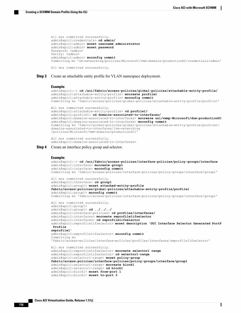
All mos committed successfully.admin@apic1:credentials> cd admin/admin@apic1:admin> moset username administratoradmin@apic1:admin> moset passwordPassword: <admin>Verify: <admin>admin@apic1:admin> moconfig commitCommitting mo 'vm-networking/policies/Microsoft/vmm-domains/productionDC/credentials/admin'
All mos committed successfully.
Step 3 Create an attachable entity profile for VLAN namespace deployment.
Example:admin@apic1:~> cd /aci/fabric/access-policies/global-policies/attachable-entity-profile/admin@apic1:attachable-entity-profile> mocreate profile1admin@apic1:attachable-entity-profile> moconfig commitCommitting mo 'fabric/access-policies/global-policies/attachable-entity-profile/profile1'
All mos committed successfully.admin@apic1:attachable-entity-profile> cd profile1/admin@apic1:profile1> cd domains-associated-to-interfaces/admin@apic1:domains-associated-to-interfaces> mocreate uni/vmmp-Microsoft/dom-productionDCadmin@apic1:domains-associated-to-interfaces> moconfig commitCommitting mo 'fabric/access-policies/global-policies/attachable-entity-profile/profile1/domains-associated-to-interfaces/[vm-networking/policies/Microsoft/vmm-domains/productionDC]'
All mos committed successfully.admin@apic1:domains-associated-to-interfaces>
Step 4 Create an interface policy group and selector.
Example:admin@apic1:~> cd /aci/fabric/access-policies/interface-policies/policy-groups/interfaceadmin@apic1:interface> mocreate group1admin@apic1:interface> moconfig commitCommitting mo 'fabric/access-policies/interface-policies/policy-groups/interface/group1'
All mos committed successfully.admin@apic1:interface> cd group1admin@apic1:group1> moset attached-entity-profilefabric/access-policies/global-policies/attachable-entity-profile/profile1admin@apic1:group1> moconfig commitCommitting mo 'fabric/access-policies/interface-policies/policy-groups/interface/group1'
All mos committed successfully.admin@apic1:group1>admin@apic1:group1> cd ../../../admin@apic1:interface-policies> cd profiles/interfaces/admin@apic1:interfaces> mocreate swprofile1ifselectoradmin@apic1:interfaces> cd swprofile1ifselectoradmin@apic1:swprofile1ifselector> moset description 'GUI Interface Selector Generated PortPProfileswprofile1'admin@apic1:swprofile1ifselector> moconfig commitCommitting mo'fabric/access-policies/interface-policies/profiles/interfaces/swprofile1ifselector'
All mos committed successfully.admin@apic1:swprofile1ifselector> mocreate selector1 rangeadmin@apic1:swprofile1ifselector> cd selector1-rangeadmin@apic1:selector1-range> moset policy-groupfabric/access-policies/interface-policies/policy-groups/interface/group1admin@apic1:selector1-range> mocreate block1admin@apic1:selector1-range> cd block1admin@apic1:block1> moset from-port 1admin@apic1:block1> moset to-port 3
Cisco ACI Virtualization Guide, Release 1.1(1j)116
Cisco ACI with Microsoft SCVMMCreating a SCVMM Domain Profile Using the CLI
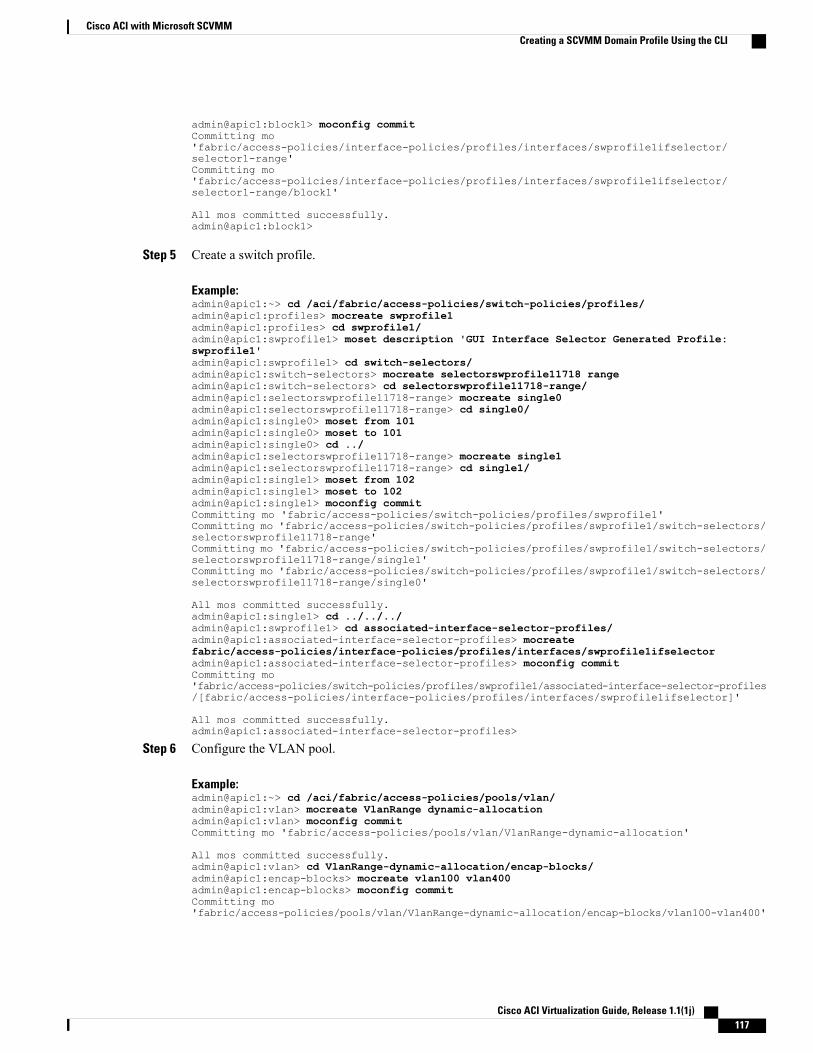
admin@apic1:block1> moconfig commitCommitting mo'fabric/access-policies/interface-policies/profiles/interfaces/swprofile1ifselector/selector1-range'Committing mo'fabric/access-policies/interface-policies/profiles/interfaces/swprofile1ifselector/selector1-range/block1'
All mos committed successfully.admin@apic1:block1>
Step 5 Create a switch profile.
Example:admin@apic1:~> cd /aci/fabric/access-policies/switch-policies/profiles/admin@apic1:profiles> mocreate swprofile1admin@apic1:profiles> cd swprofile1/admin@apic1:swprofile1> moset description 'GUI Interface Selector Generated Profile:swprofile1'admin@apic1:swprofile1> cd switch-selectors/admin@apic1:switch-selectors> mocreate selectorswprofile11718 rangeadmin@apic1:switch-selectors> cd selectorswprofile11718-range/admin@apic1:selectorswprofile11718-range> mocreate single0admin@apic1:selectorswprofile11718-range> cd single0/admin@apic1:single0> moset from 101admin@apic1:single0> moset to 101admin@apic1:single0> cd ../admin@apic1:selectorswprofile11718-range> mocreate single1admin@apic1:selectorswprofile11718-range> cd single1/admin@apic1:single1> moset from 102admin@apic1:single1> moset to 102admin@apic1:single1> moconfig commitCommitting mo 'fabric/access-policies/switch-policies/profiles/swprofile1'Committing mo 'fabric/access-policies/switch-policies/profiles/swprofile1/switch-selectors/selectorswprofile11718-range'Committing mo 'fabric/access-policies/switch-policies/profiles/swprofile1/switch-selectors/selectorswprofile11718-range/single1'Committing mo 'fabric/access-policies/switch-policies/profiles/swprofile1/switch-selectors/selectorswprofile11718-range/single0'
All mos committed successfully.admin@apic1:single1> cd ../../../admin@apic1:swprofile1> cd associated-interface-selector-profiles/admin@apic1:associated-interface-selector-profiles> mocreatefabric/access-policies/interface-policies/profiles/interfaces/swprofile1ifselectoradmin@apic1:associated-interface-selector-profiles> moconfig commitCommitting mo'fabric/access-policies/switch-policies/profiles/swprofile1/associated-interface-selector-profiles/[fabric/access-policies/interface-policies/profiles/interfaces/swprofile1ifselector]'
All mos committed successfully.admin@apic1:associated-interface-selector-profiles>
Step 6 Configure the VLAN pool.
Example:admin@apic1:~> cd /aci/fabric/access-policies/pools/vlan/admin@apic1:vlan> mocreate VlanRange dynamic-allocationadmin@apic1:vlan> moconfig commitCommitting mo 'fabric/access-policies/pools/vlan/VlanRange-dynamic-allocation'
All mos committed successfully.admin@apic1:vlan> cd VlanRange-dynamic-allocation/encap-blocks/admin@apic1:encap-blocks> mocreate vlan100 vlan400admin@apic1:encap-blocks> moconfig commitCommitting mo'fabric/access-policies/pools/vlan/VlanRange-dynamic-allocation/encap-blocks/vlan100-vlan400'
Cisco ACI Virtualization Guide, Release 1.1(1j) 117
Cisco ACI with Microsoft SCVMMCreating a SCVMM Domain Profile Using the CLI
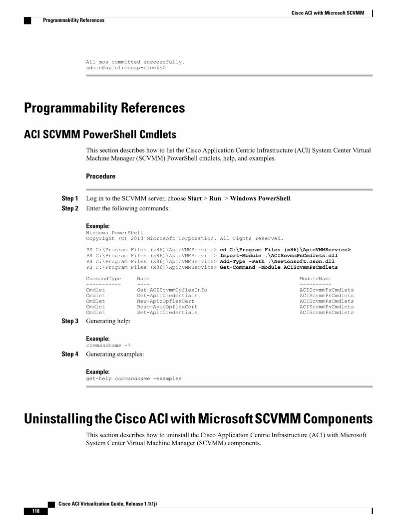
All mos committed successfully.admin@apic1:encap-blocks>
Programmability References
ACI SCVMM PowerShell CmdletsThis section describes how to list the Cisco Application Centric Infrastructure (ACI) System Center VirtualMachine Manager (SCVMM) PowerShell cmdlets, help, and examples.
Procedure
Step 1 Log in to the SCVMM server, choose Start > Run >Windows PowerShell.Step 2 Enter the following commands:
Example:Windows PowerShellCopyright (C) 2013 Microsoft Corporation. All rights reserved.
PS C:\Program Files (x86)\ApicVMMService> cd C:\Program Files (x86)\ApicVMMService>PS C:\Program Files (x86)\ApicVMMService> Import-Module .\ACIScvmmPsCmdlets.dllPS C:\Program Files (x86)\ApicVMMService> Add-Type -Path .\Newtonsoft.Json.dllPS C:\Program Files (x86)\ApicVMMService> Get-Command -Module ACIScvmmPsCmdlets
CommandType Name ModuleName----------- ---- ----------Cmdlet Get-ACIScvmmOpflexInfo ACIScvmmPsCmdletsCmdlet Get-ApicCredentials ACIScvmmPsCmdletsCmdlet New-ApicOpflexCert ACIScvmmPsCmdletsCmdlet Read-ApicOpflexCert ACIScvmmPsCmdletsCmdlet Set-ApicCredentials ACIScvmmPsCmdlets
Step 3 Generating help:
Example:commandname -?
Step 4 Generating examples:
Example:get-help commandname -examples
Uninstalling the Cisco ACI with Microsoft SCVMM ComponentsThis section describes how to uninstall the Cisco Application Centric Infrastructure (ACI) with MicrosoftSystem Center Virtual Machine Manager (SCVMM) components.
Cisco ACI Virtualization Guide, Release 1.1(1j)118
Cisco ACI with Microsoft SCVMMProgrammability References
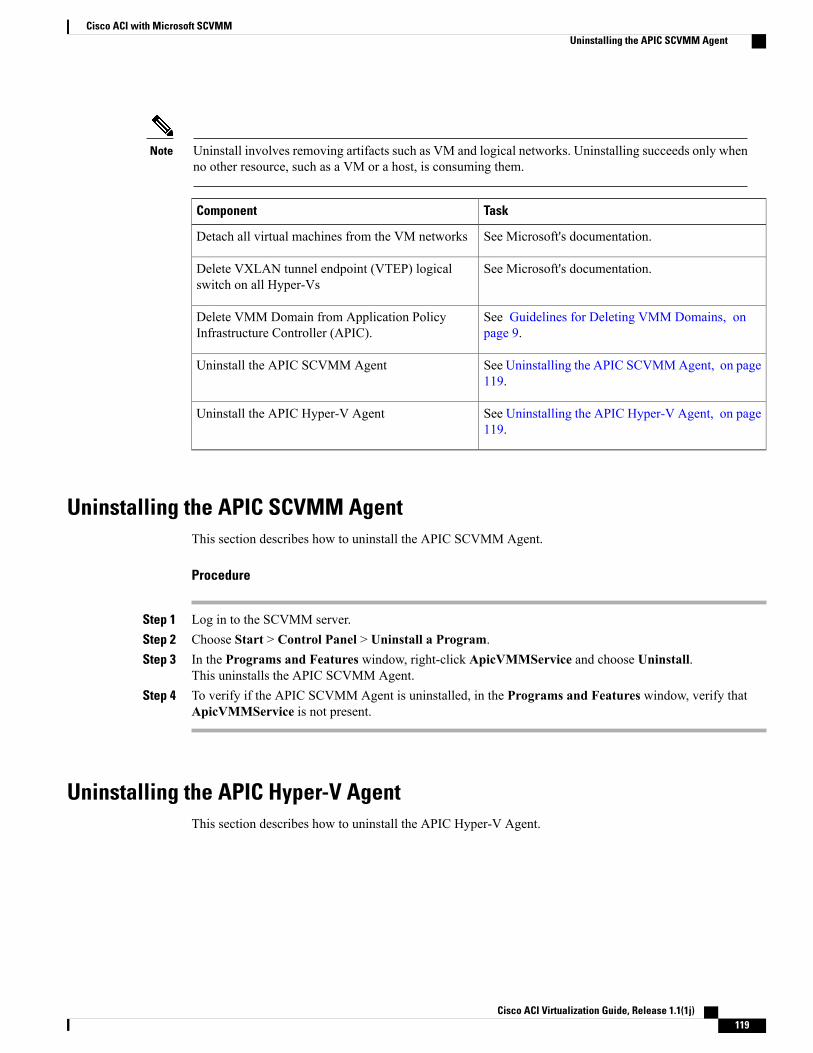
Uninstall involves removing artifacts such as VM and logical networks. Uninstalling succeeds only whenno other resource, such as a VM or a host, is consuming them.
Note
TaskComponent
See Microsoft's documentation.Detach all virtual machines from the VM networks
See Microsoft's documentation.Delete VXLAN tunnel endpoint (VTEP) logicalswitch on all Hyper-Vs
See Guidelines for Deleting VMM Domains, onpage 9.
Delete VMM Domain from Application PolicyInfrastructure Controller (APIC).
See Uninstalling the APIC SCVMMAgent, on page119.
Uninstall the APIC SCVMM Agent
See Uninstalling the APIC Hyper-V Agent, on page119.
Uninstall the APIC Hyper-V Agent
Uninstalling the APIC SCVMM AgentThis section describes how to uninstall the APIC SCVMM Agent.
Procedure
Step 1 Log in to the SCVMM server.Step 2 Choose Start > Control Panel > Uninstall a Program.Step 3 In the Programs and Features window, right-click ApicVMMService and choose Uninstall.
This uninstalls the APIC SCVMM Agent.Step 4 To verify if the APIC SCVMM Agent is uninstalled, in the Programs and Features window, verify that
ApicVMMService is not present.
Uninstalling the APIC Hyper-V AgentThis section describes how to uninstall the APIC Hyper-V Agent.
Cisco ACI Virtualization Guide, Release 1.1(1j) 119
Cisco ACI with Microsoft SCVMMUninstalling the APIC SCVMM Agent
Procedure
Step 1 Log in to the Hyper-V server.Step 2 Choose Start > Control Panel > Uninstall a Program.Step 3 In the Programs and Features window, right-click Cisco APIC Hyper-V Agent and choose Uninstall.
This uninstalls the APIC Hyper-V Agent from the Hyper-V server.Step 4 To verify if the APIC Hyper-V Agent is uninstalled, perform the following actions:
a) Choose Start > Control Panel > Uninstall a Program.b) In the Programs and Features window, verify that Cisco APIC Hyper-V Agent is not present.
Step 5 Repeat steps 1-4 for each Hyper-V server.
Downgrading the APIC Controller and the Switch Software withCisco ACI with Microsoft SCVMM Components
This section describes how to downgrade the APIC controller and the switch software with Cisco ACI withMicrosoft System Center Virtual Machine Manager (SCVMM) Components.
Procedure
Step 1 Uninstall Cisco ACI with Microsoft SCVMM components.See Uninstalling the Cisco ACI with Microsoft SCVMM Components, on page 118.
Step 2 Downgrade the APIC controller and the switch software.See the Cisco APIC Firmware Management Guide.
Cisco ACI Virtualization Guide, Release 1.1(1j)120
Cisco ACI with Microsoft SCVMMDowngrading the APIC Controller and the Switch Software with Cisco ACI with Microsoft SCVMM Components
C H A P T E R 5Cisco ACI with Microsoft Windows Azure Pack
This chapter contains the following sections:
• About Cisco ACI with Microsoft Windows Azure Pack, page 121
• Getting Started with Cisco ACI with Microsoft Windows Azure Pack, page 125
• Use Case Scenarios for the Administrator and Tenant Experience, page 136
• Troubleshooting Cisco ACI with Microsoft Windows Azure Pack, page 157
• REST API References, page 158
• Programmability, page 158
• Uninstalling the Cisco ACI with Microsoft Windows Azure Pack Components, page 160
• Downgrading the APIC Controller and the Switch Software with Cisco ACI with Microsoft WindowsAzure Pack Components, page 161
About Cisco ACI with Microsoft Windows Azure PackCisco Application Centric Infrastructure (ACI) integrates in Microsoft Windows Azure Pack to provide aself-service experience for the tenant.
ACI enhances the network management capabilities of the platform. ACI integrates in one of the two modes:
• Cisco ACI with Microsoft Windows Azure Pack—Microsoft Windows Azure Pack for Windows Serveris a collection of Microsoft Azure technologies that include the following capabilities:
◦Management portal for tenants
◦Management portal for administrators
◦Service management API
• Cisco ACI with Microsoft System Center Virtual Machine Manager—For information about how toset up Cisco ACI with Microsoft System Center Virtual Machine Manager (SCVMM), see details inCisco ACI with Microsoft SCVMM Solution Overview, on page 89.
Cisco ACI Virtualization Guide, Release 1.1(1j) 121
Cisco ACI with Microsoft Windows Azure Pack Solution OverviewIn this mode Cisco Application Centric Infrastructure (ACI) integrates in Microsoft Windows Azure Pack toprovide a self-service experience for tenants. ACI resource provider in Windows Azure Pack drives theApplication Policy Infrastructure Controller (APIC) for network management. Networks are created in SystemCenter Virtual MachineManager (SCVMM) and are available inWindows Azure Pack for respective tenants.ACI Layer 4 to Layer 7 capabilities for F5 and Citrix load balancers and stateless firewall are provided fortenants. For details, see the About Load Balancing, on page 143.
Windows Azure Pack for Windows Server is a collection of Microsoft Azure technologies, available toMicrosoft customers at no additional cost for installation into your data center. It runs on top of WindowsServer 2012 R2 and System Center 2012 R2 and, through the use of theWindows Azure technologies, enablesyou to offer a rich, self-service, multi-tenant cloud, consistent with the public Windows Azure experience.
Windows Azure Pack includes the following capabilities:
• Management portal for tenants—a customizable self-service portal for provisioning, monitoring, andmanaging services such as networks, bridge domains, VMs, firewalls, load balancers, and shared services.See the User Portal GUI.
• Management portal for administrators—a portal for administrators to configure and manage resourceclouds, user accounts, and tenant offers, quotas, pricing, Web Site Clouds, Virtual Machine Clouds, andService Bus Clouds.
• Service management API—a REST API that helps enable a range of integration scenarios includingcustom portal and billing systems.
See Use Case Scenarios for the Administrator and Tenant Experience, on page 136 for details.
Cisco ACI Virtualization Guide, Release 1.1(1j)122
Cisco ACI with Microsoft Windows Azure PackCisco ACI with Microsoft Windows Azure Pack Solution Overview
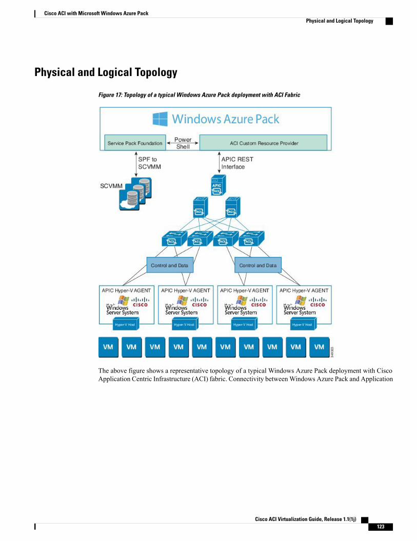
Physical and Logical Topology
Figure 17: Topology of a typical Windows Azure Pack deployment with ACI Fabric
The above figure shows a representative topology of a typical Windows Azure Pack deployment with CiscoApplication Centric Infrastructure (ACI) fabric. Connectivity betweenWindows Azure Pack and Application
Cisco ACI Virtualization Guide, Release 1.1(1j) 123
Cisco ACI with Microsoft Windows Azure PackPhysical and Logical Topology
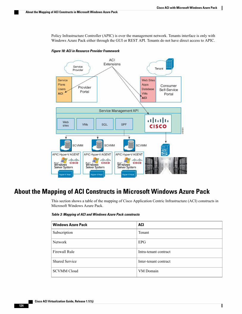
Policy Infrastructure Controller (APIC) is over the management network. Tenants interface is only withWindows Azure Pack either through the GUI or REST API. Tenants do not have direct access to APIC.
Figure 18: ACI in Resource Provider Framework
About the Mapping of ACI Constructs in Microsoft Windows Azure PackThis section shows a table of the mapping of Cisco Application Centric Infrastructure (ACI) constructs inMicrosoft Windows Azure Pack.
Table 3: Mapping of ACI and Windows Azure Pack constructs
ACIWindows Azure Pack
TenantSubscription
EPGNetwork
Intra-tenant contractFirewall Rule
Inter-tenant contractShared Service
VM DomainSCVMM Cloud
Cisco ACI Virtualization Guide, Release 1.1(1j)124
Cisco ACI with Microsoft Windows Azure PackAbout the Mapping of ACI Constructs in Microsoft Windows Azure Pack
Getting Started with Cisco ACI with Microsoft Windows AzurePack
This section describes how to get started with Cisco ACI with Microsoft Windows Azure Pack.
You must download and unzip the Cisco ACI and Microsoft Integration file for the 1.1(1j) release beforeinstalling Cisco ACI with Microsoft Windows Azure Pack.
1 Go to Cisco's Application Policy Infrastructure Controller (APIC) Website:
http://www.cisco.com/c/en/us/support/cloud-systems-management/application-policy-infrastructure-controller-apic/tsd-products-support-series-home.html
2 Choose Download Software.
3 Choose the release version and the aci-msft-pkg-1.1.1j.zip file.
4 Click Download.
5 Unzip the aci-msft-pkg-1.1.1j.zip file.
Cisco ACI with Microsoft Windows Azure Pack only supports ASCII characters. Non-ASCII charactersare not supported.
Note
Prerequisites for Getting Started with Cisco ACI and Microsoft Windows AzurePack
Before you get started, ensure that you have verified that your computing environment meets the followingprerequisites:
• Ensure Microsoft Windows Azure Pack Update Rollup 5 is installed.
See Microsoft's documentation.
• Ensure Microsoft System Center 2012 R2 - Virtual Machine Manager (SCVMM) is installed.
See Microsoft's documentation.
• Ensure Hyper-V Host is installed.
See Microsoft's documentation.
• Ensure a cloud is configured on SCVMM.
See Microsoft's documentation.
• Ensure a VM cloud is configured on Windows Azure Pack.
See Microsoft's documentation.
• Ensure "default" AEP exists with infrastructure VLAN enabled.
Cisco ACI Virtualization Guide, Release 1.1(1j) 125
Cisco ACI with Microsoft Windows Azure PackGetting Started with Cisco ACI with Microsoft Windows Azure Pack
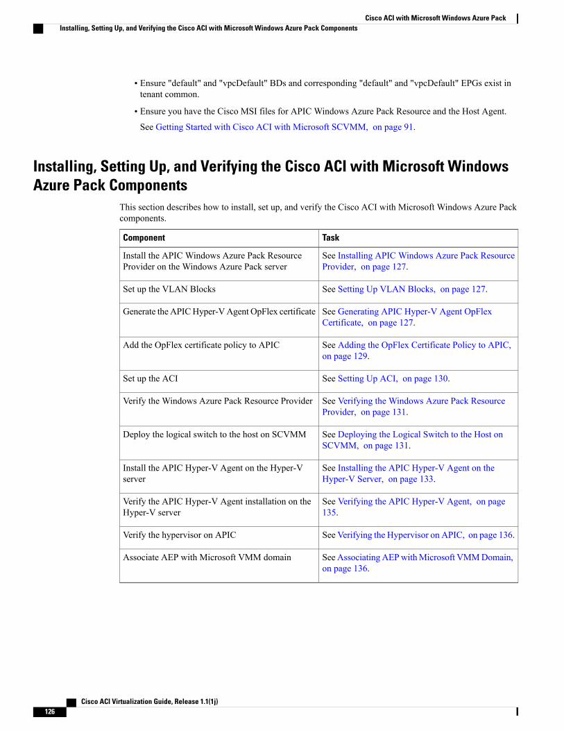
• Ensure "default" and "vpcDefault" BDs and corresponding "default" and "vpcDefault" EPGs exist intenant common.
• Ensure you have the Cisco MSI files for APIC Windows Azure Pack Resource and the Host Agent.
See Getting Started with Cisco ACI with Microsoft SCVMM, on page 91.
Installing, Setting Up, and Verifying the Cisco ACI with Microsoft WindowsAzure Pack Components
This section describes how to install, set up, and verify the Cisco ACI with Microsoft Windows Azure Packcomponents.
TaskComponent
See Installing APIC Windows Azure Pack ResourceProvider, on page 127.
Install the APIC Windows Azure Pack ResourceProvider on the Windows Azure Pack server
See Setting Up VLAN Blocks, on page 127.Set up the VLAN Blocks
See Generating APIC Hyper-V Agent OpFlexCertificate, on page 127.
Generate the APICHyper-VAgent OpFlex certificate
See Adding the OpFlex Certificate Policy to APIC,on page 129.
Add the OpFlex certificate policy to APIC
See Setting Up ACI, on page 130.Set up the ACI
See Verifying the Windows Azure Pack ResourceProvider, on page 131.
Verify the Windows Azure Pack Resource Provider
See Deploying the Logical Switch to the Host onSCVMM, on page 131.
Deploy the logical switch to the host on SCVMM
See Installing the APIC Hyper-V Agent on theHyper-V Server, on page 133.
Install the APIC Hyper-V Agent on the Hyper-Vserver
See Verifying the APIC Hyper-V Agent, on page135.
Verify the APIC Hyper-V Agent installation on theHyper-V server
See Verifying the Hypervisor on APIC, on page 136.Verify the hypervisor on APIC
See Associating AEPwithMicrosoft VMMDomain,on page 136.
Associate AEP with Microsoft VMM domain
Cisco ACI Virtualization Guide, Release 1.1(1j)126
Cisco ACI with Microsoft Windows Azure PackInstalling, Setting Up, and Verifying the Cisco ACI with Microsoft Windows Azure Pack Components

Installing APIC Windows Azure Pack Resource ProviderThis section describes how to install APIC Windows Azure Pack Resource Provider on the Windows AzurePack server.
Procedure
Step 1 Log in to theWindows Azure Pack server and locate theAPICWindows Azure PackResource Provider.msifile.
Step 2 Double-click the APIC Windows Azure Pack Resource Provider.msi file.Step 3 In theWindows Azure Pack: Sample Setup dialog box, perform the following actions to install APIC
Windows Azure Pack Resource Provider:a) Check the I accept the terms in the License Agreement check box.b) Click Next.c) Enter your account name and password credentials for Windows Azure Pack and click Next.d) Click Next.e) Click Install.f) Click Finish.
Setting Up VLAN BlocksThis section describes how to setup VLAN blocks.
Procedure
Step 1 Log in to the Service Management Portal, choose ACI > VLAN BLOCKS.Step 2 Click ADD at the bottom.Step 3 In the ADD dialog box, perform the following actions:
a) In the START VLAN field, enter VLAN ID (100).b) In the END VLAN field, enter VLAN ID (200).c) In the SCVMM STAMP field, from the drop-down list, choose the SCVMM stamp (dev8-scvmm).d) In the CLOUD NAME field, from the drop-down list, choose the cloud name (Cloud01).e) Click the checkmark.
Generating APIC Hyper-V Agent OpFlex CertificateThis section describes how to generate APIC Hyper-V Agent OpFlex certificate to secure communicationbetween the Application Policy Infrastructure Controller (APIC) and Hyper-V agent.
Cisco ACI Virtualization Guide, Release 1.1(1j) 127
Cisco ACI with Microsoft Windows Azure PackInstalling, Setting Up, and Verifying the Cisco ACI with Microsoft Windows Azure Pack Components

This should only be done once per installation.Note
Procedure
Step 1 On the Windows Azure Pack Server, choose Start > Run >Windows PowerShell, and then, in the app bar,click Run as administrator.
Step 2 Load ACIWapPsCmdlets and create a new OpflexAgent.pfx certificate file, by entering the followingcommands:Windows PowerShellCopyright (C) 2013 Microsoft Corporation. All rights reserved.
PS C:\Users\Administrator.INSCISCO> cd \PS C:\> cd C:\inetpub\Mgmt-ACI\binPS C:\inetpub\Mgmt-ACI\bin> Import-Module .\ACIWapPsCmdlets.dllPS C:\inetpub\Mgmt-ACI\bin> Get-Command -Module ACIWapPsCmdlets
CommandType Name ModuleName----------- ---- ----------Cmdlet Add-ACIWAPEndpointGroup ACIWapPsCmdletsCmdlet Get-ACIWAPAdminObjects ACIWapPsCmdletsCmdlet Get-ACIWAPAllEndpointGroups ACIWapPsCmdletsCmdlet Get-ACIWAPBDSubnets ACIWapPsCmdletsCmdlet Get-ACIWAPConsumersForSharedService ACIWapPsCmdletsCmdlet Get-ACIWAPEndpointGroups ACIWapPsCmdletsCmdlet Get-ACIWAPEndpoints ACIWapPsCmdletsCmdlet Get-ACIWAPLBConfiguration ACIWapPsCmdletsCmdlet Get-ACIWAPOpflexInfo ACIWapPsCmdletsCmdlet Get-ACIWAPPlans ACIWapPsCmdletsCmdlet Get-ACIWAPStatelessFirewall ACIWapPsCmdletsCmdlet Get-ACIWAPSubscriptions ACIWapPsCmdletsCmdlet Get-ACIWAPTenantPlan ACIWapPsCmdletsCmdlet Get-ACIWAPTenantSharedService ACIWapPsCmdletsCmdlet Get-ACIWAPVlanNamespace ACIWapPsCmdletsCmdlet New-ApicOpflexCert ACIWapPsCmdletsCmdlet Read-ApicOpflexCert ACIWapPsCmdletsCmdlet Remove-ACIWAPEndpointGroup ACIWapPsCmdletsCmdlet Remove-ACIWAPPlan ACIWapPsCmdletsCmdlet Set-ACIWAPAdminLogin ACIWapPsCmdletsCmdlet Set-ACIWAPBDSubnets ACIWapPsCmdletsCmdlet Set-ACIWAPLBConfiguration ACIWapPsCmdletsCmdlet Set-ACIWAPLogin ACIWapPsCmdletsCmdlet Set-ACIWAPOpflexOperation ACIWapPsCmdletsCmdlet Set-ACIWAPPlan ACIWapPsCmdletsCmdlet Set-ACIWAPStatelessFirewall ACIWapPsCmdletsCmdlet Set-ACIWAPTenantSharedService ACIWapPsCmdletsCmdlet Set-ACIWAPUpdateShareServiceConsumption ACIWapPsCmdletsCmdlet Set-ACIWAPVlanNamespace ACIWapPsCmdlets
PS C:\inetpub\MgmtSvc-ACI\bin>
Cisco ACI Virtualization Guide, Release 1.1(1j)128
Cisco ACI with Microsoft Windows Azure PackInstalling, Setting Up, and Verifying the Cisco ACI with Microsoft Windows Azure Pack Components
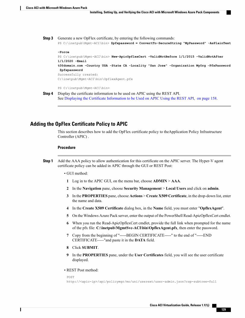
Step 3 Generate a new OpFlex certificate, by entering the following commands:PS C:\inetpub\Mgmt-ACI\bin> $pfxpassword = ConvertTo-SecureString "MyPassword" -AsPlainText
-ForcePS C:\inetpub\Mgmt-ACI\bin> New-ApicOpflexCert -ValidNotBefore 1/1/2015 -ValidNotAfter1/1/2020 [email protected] -Country USA -State CA -Locality "San Jose" -Organization MyOrg –PfxPassword$pfxpasswordSuccessfully created:C:\inetpub\Mgmt-ACI\bin\OpflexAgent.pfx
PS C:\inetpub\Mgmt-ACI\bin>
Step 4 Display the certificate information to be used on APIC using the REST API.See Displaying the Certificate Information to be Used on APIC Using the REST API, on page 158.
Adding the OpFlex Certificate Policy to APICThis section describes how to add the OpFlex certificate policy to theApplication Policy InfrastructureController (APIC) .
Procedure
Step 1 Add the AAA policy to allow authentication for this certificate on the APIC server. The Hyper-V agentcertificate policy can be added in APIC through the GUI or REST Post:
• GUI method:
1 Log in to the APIC GUI, on the menu bar, choose ADMIN > AAA.
2 In the Navigation pane, choose Security Management > Local Users and click on admin.
3 In the PROPERTIES pane, chooseActions >Create X509 Certificate, in the drop-down list, enterthe name and data.
4 In the Create X509 Certificate dialog box, in the Name field, you must enter "OpflexAgent".
5 On theWindows Azure Pack server, enter the output of the PowerShell Read-ApicOpflexCert cmdlet.
6 When you run the Read-ApicOpflexCert cmdlet, provide the full link when prompted for the nameof the pfx file: C:\inetpub\MgmtSvc-ACI\bin\OpflexAgent.pfx, then enter the password.
7 Copy from the beginning of "-----BEGIN CERTIFICATE-----" to the end of "-----ENDCERTIFICATE-----"and paste it in the DATA field.
8 Click SUBMIT.
9 In the PROPERTIES pane, under the User Certificates field, you will see the user certificatedisplayed.
• REST Post method:
POSThttp://<apic-ip>/api/policymgr/mo/uni/userext/user-admin.json?rsp-subtree=full
Cisco ACI Virtualization Guide, Release 1.1(1j) 129
Cisco ACI with Microsoft Windows Azure PackInstalling, Setting Up, and Verifying the Cisco ACI with Microsoft Windows Azure Pack Components
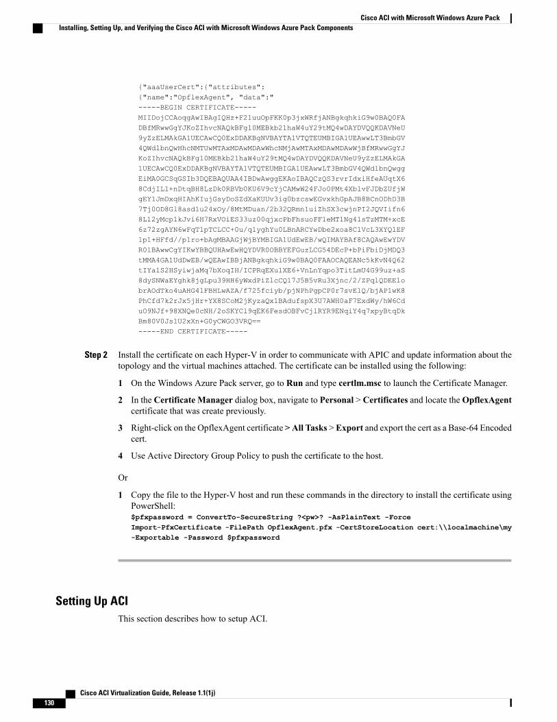
{"aaaUserCert":{"attributes":{"name":"OpflexAgent", "data":"-----BEGIN CERTIFICATE-----MIIDojCCAoqgAwIBAgIQHz+F2luuOpFKK0p3jxWRfjANBgkqhkiG9w0BAQ0FADBfMRwwGgYJKoZIhvcNAQkBFg10MEBkb21haW4uY29tMQ4wDAYDVQQKDAVNeU9yZzELMAkGA1UECAwCQ0ExDDAKBgNVBAYTA1VTQTEUMBIGA1UEAwwLT3BmbGV4QWdlbnQwHhcNMTUwMTAxMDAwMDAwWhcNMjAwMTAxMDAwMDAwWjBfMRwwGgYJKoZIhvcNAQkBFg10MEBkb21haW4uY29tMQ4wDAYDVQQKDAVNeU9yZzELMAkGA1UECAwCQ0ExDDAKBgNVBAYTA1VTQTEUMBIGA1UEAwwLT3BmbGV4QWdlbnQwggEiMA0GCSqGSIb3DQEBAQUAA4IBDwAwggEKAoIBAQCzQS3rvrIdxiHfeAUqtX68CdjIL1+nDtqBH8LzDk0RBVb0KU6V9cYjCAMwW24FJo0PMt4XblvFJDbZUfjWgEY1JmDxqHIAhKIujGsyDoSZdXaKUUv3ig0bzcswEGvxkhGpAJB8BCnODhD3B7Tj0OD8Gl8asd1u24xOy/8MtMDuan/2b32QRmn1uiZhSX3cwjnPI2JQVIifn68L12yMcp1kJvi6H7RxVOiES33uz00qjxcPbFhsuoFF1eMT1Ng41sTzMTM+xcE6z72zgAYN6wFqT1pTCLCC+0u/q1yghYu0LBnARCYwDbe2xoa8ClVcL3XYQlEFlp1+HFfd//p1ro+bAgMBAAGjWjBYMBIGA1UdEwEB/wQIMAYBAf8CAQAwEwYDVR0lBAwwCgYIKwYBBQUHAwEwHQYDVR0OBBYEFGuzLCG54DEcP+bPiFbiDjMDQ3tMMA4GA1UdDwEB/wQEAwIBBjANBgkqhkiG9w0BAQ0FAAOCAQEANc5kKvN4Q62tIYa1S2HSyiwjaMq7bXoqIH/ICPRqEXu1XE6+VnLnYqpo3TitLmU4G99uz+aS8dySNWaEYghk8jgLpu39HH6yWxdPiZlcCQ17J5B5vRu3Xjnc/2/ZPqlQDEElobrAOdTko4uAHG4lFBHLwAZA/f725fciyb/pjNPhPgpCP0r7svElQ/bjAP1wK8PhCfd7k2rJx5jHr+YX8SCoM2jKyzaQx1BAdufspX3U7AWH0aF7ExdWy/hW6CduO9NJf+98XNQe0cNH/2oSKYCl9qEK6FesdOBFvCjlRYR9ENqiY4q7xpyBtqDkBm80V0JslU2xXn+G0yCWGO3VRQ==-----END CERTIFICATE-----
Step 2 Install the certificate on each Hyper-V in order to communicate with APIC and update information about thetopology and the virtual machines attached. The certificate can be installed using the following:
1 On the Windows Azure Pack server, go to Run and type certlm.msc to launch the Certificate Manager.
2 In the Certificate Manager dialog box, navigate to Personal > Certificates and locate theOpflexAgentcertificate that was create previously.
3 Right-click on the OpflexAgent certificate >All Tasks >Export and export the cert as a Base-64 Encodedcert.
4 Use Active Directory Group Policy to push the certificate to the host.
Or
1 Copy the file to the Hyper-V host and run these commands in the directory to install the certificate usingPowerShell:$pfxpassword = ConvertTo-SecureString ?<pw>? -AsPlainText -ForceImport-PfxCertificate -FilePath OpflexAgent.pfx -CertStoreLocation cert:\\localmachine\my-Exportable -Password $pfxpassword
Setting Up ACIThis section describes how to setup ACI.
Cisco ACI Virtualization Guide, Release 1.1(1j)130
Cisco ACI with Microsoft Windows Azure PackInstalling, Setting Up, and Verifying the Cisco ACI with Microsoft Windows Azure Pack Components
Procedure
Step 1 Log in to the Service Management Portal.Step 2 In the navigation pane, choose ACI.
If you do not see ACI, click Refresh.
Step 3 In the ACI Setup pane, perform the following actions in order:a) In the ENDPOINT URL field, enter the address:port (127.0.0.1:50030).b) In the APIC ADDRESS field, enter the APIC IP address (172.23.138.149).c) In the USERSNAME field, enter the user name (admin).d) In the PASSWORD field, enter the password.When the ACI setup is completed, the ACI pane displays ACI set up is now complete.
Verifying the Windows Azure Pack Resource ProviderThis section describes how to verify the Windows Azure Pack Resource Provider.
Procedure
Step 1 Log in to the Service Management Portal (Admin Portal).Step 2 In the navigation pane, choose ACI.Step 3 In the aci pane, choose SETUP.
Ensure you can see the APIC version. This confirms communication between Windows Azure Pack Agentand APIC.
Step 4 In the aci pane, choose VLAN BLOCKS.Ensure you see the cloud name with their SCVMM.
Deploying the Logical Switch to the Host on SCVMMThis section describes how to deploy the logical switch to the host on System Center Virtual MachineManager(SCVMM).
Procedure
Step 1 (Optional) To configure logical switch uplink profile:The default configuration is Switch Independent and Hyper-V Port.
Supported values:
Cisco ACI Virtualization Guide, Release 1.1(1j) 131
Cisco ACI with Microsoft Windows Azure PackInstalling, Setting Up, and Verifying the Cisco ACI with Microsoft Windows Azure Pack Components
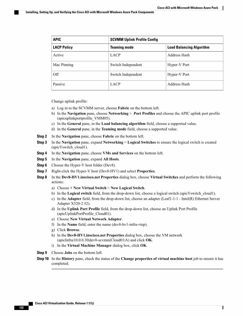
SCVMM Uplink Profile ConfigAPIC
Load Balancing AlgorithmTeaming modeLACP Policy
Address HashLACPActive
Hyper-V PortSwitch IndependentMac Pinning
Hyper-V PortSwitch IndependentOff
Address HashLACPPassive
Change uplink profile:
a) Log in to the SCVMM server, choose Fabric on the bottom left.b) In the Navigation pane, choose Networking > Port Profiles and choose the APIC uplink port profile
(apicuplinkportprofile_VMM05).c) In the General pane, in the Load balancing algorithm field, choose a supported value.d) In the General pane, in the Teaming mode field, choose a supported value.
Step 2 In the Navigation pane, choose Fabric on the bottom left.Step 3 In the Navigation pane, expand Networking > Logical Switches to ensure the logical switch is created
(apicVswitch_cloud1).Step 4 In the Navigation pane, choose VMs and Services on the bottom left.Step 5 In the Navigation pane, expand All Hosts.Step 6 Choose the Hyper-V host folder (Dev8).Step 7 Right-click the Hyper-V host (Dev8-HV1) and select Properties.Step 8 In the Dev8-HV1.inscisco.net Properties dialog box, choose Virtual Switches and perform the following
actions:a) Choose + New Virtual Switch > New Logical Switch.b) In the Logical switch field, from the drop-down list, choose a logical switch (apicVswitch_cloud1).c) In the Adapter field, from the drop-down list, choose an adapter (Leaf1-1-1 - Intel(R) Ethernet Server
Adapter X520-2 #2).d) In the Uplink Port Profile field, from the drop-down list, choose an Uplink Port Profile
(apicUplinkPortProfile_Cloud01).e) Choose New Virtual Network Adapter.f) In the Name field, enter the name (dev8-hv1-infra-vtep).g) Click Browse.h) In the Dev8-HV1.inscisco.net Properties dialog box, choose the VM network
(apicInfra|10.0.0.30|dev8-scvmm|Cloud01|A) and click OK.i) In the Virtual Machine Manager dialog box, click OK.
Step 9 Choose Jobs on the bottom left.Step 10 In the History pane, check the status of the Change properties of virtual machine host job to ensure it has
completed.
Cisco ACI Virtualization Guide, Release 1.1(1j)132
Cisco ACI with Microsoft Windows Azure PackInstalling, Setting Up, and Verifying the Cisco ACI with Microsoft Windows Azure Pack Components
Installing the APIC Hyper-V Agent on the Hyper-V ServerThis section describes how to install the APIC Hyper-V Agent on the Hyper-V server.
Option 1 is by logging into the Windows Azure Pack AdminSite Portal and navigating toACI >Hypervisor.
For option 2 follow these steps:
Procedure
Step 1 Log in to the Hyper-V server with administrator credentials.Step 2 On the Hyper-V server in explorer, locate the APIC Hyper-V Agent.msi file.Step 3 Right-click the APIC Hyper-V Agent.msi file and choose Install.Step 4 In the Cisco APIC Hyper-V Agent Setup dialog box, perform the following actions:
a) Check the I accept the terms in the License Agreement check box.b) Click Install.c) Click Finish.
Step 5 Use one of the following methods:
• For large scale deployments, see Microsoft's documentation for Deploy Certificates by Using GroupPolicy:
https://technet.microsoft.com/en-us/library/cc770315(v=ws.10).aspx.
• For small scale deployments follow these steps:
Youmust add OpFlex security certificate in the local system. TheMicrosoft Hyper-V agent has a securitycertificate file namedOpflexAgent.pfx located in theC:\inetpub\Mgmt-ACI\bin folder on theWindowsAzure Pack server. If the following steps are not performed on your Hyper-V servers then the APICHyper-V Agent cannot communicate with the Cisco Application Centric Infrastructure (ACI) fabric leafswitches.
Install the OpFlex security certificate on the Hyper-V Windows Server 2012 local machine’s certificaterepository. On each Hyper-V server, install this certificate by performing the following steps:
1 Choose Start > Run.
2 Entermmc and click OK.
3 In the Console Root window, on the menu bar, choose Add/Remove Snap-in.
4 In the Available Snap-ins field, choose Certificates and click Add.
5 In theCertificates snap-in dialog box, choose theComputer Account radio button, and clickNext.
6 In the Select Computer dialog box, choose the Local Computer radio button, and click Finish.
7 Click OK to go back to mainMMC Console window.
8 In theMMC Console window, double-click Certificates (local computer) to expand its view.
9 Right-click Certificates under Personal and choose All Tasks > Import.
10 In the Certificates Import Wizard dialog box, perform the following actions:
a Click Next.
Cisco ACI Virtualization Guide, Release 1.1(1j) 133
Cisco ACI with Microsoft Windows Azure PackInstalling, Setting Up, and Verifying the Cisco ACI with Microsoft Windows Azure Pack Components
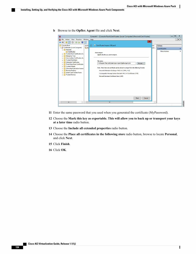
b Browse to the Opflex Agent file and click Next.
11 Enter the same password that you used when you generated the certificate (MyPassword).
12 Choose theMark this key as exportable. This will allow you to back up or transport your keysat a later time radio button.
13 Choose the Include all extended properties radio button.
14 Choose the Place all certificates in the following store radio button, browse to locate Personal,and click Next.
15 Click Finish.
16 Click OK.
Cisco ACI Virtualization Guide, Release 1.1(1j)134
Cisco ACI with Microsoft Windows Azure PackInstalling, Setting Up, and Verifying the Cisco ACI with Microsoft Windows Azure Pack Components
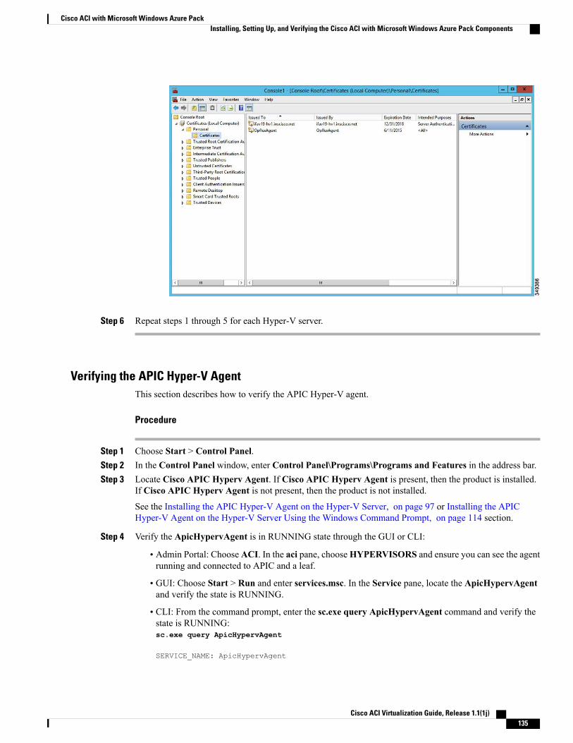
Step 6 Repeat steps 1 through 5 for each Hyper-V server.
Verifying the APIC Hyper-V AgentThis section describes how to verify the APIC Hyper-V agent.
Procedure
Step 1 Choose Start > Control Panel.Step 2 In the Control Panel window, enter Control Panel\Programs\Programs and Features in the address bar.Step 3 Locate Cisco APIC Hyperv Agent. If Cisco APIC Hyperv Agent is present, then the product is installed.
If Cisco APIC Hyperv Agent is not present, then the product is not installed.
See the Installing the APIC Hyper-V Agent on the Hyper-V Server, on page 97 or Installing the APICHyper-V Agent on the Hyper-V Server Using the Windows Command Prompt, on page 114 section.
Step 4 Verify the ApicHypervAgent is in RUNNING state through the GUI or CLI:
• Admin Portal: Choose ACI. In the aci pane, chooseHYPERVISORS and ensure you can see the agentrunning and connected to APIC and a leaf.
• GUI: Choose Start > Run and enter services.msc. In the Service pane, locate the ApicHypervAgentand verify the state is RUNNING.
• CLI: From the command prompt, enter the sc.exe query ApicHypervAgent command and verify thestate is RUNNING:sc.exe query ApicHypervAgent
SERVICE_NAME: ApicHypervAgent
Cisco ACI Virtualization Guide, Release 1.1(1j) 135
Cisco ACI with Microsoft Windows Azure PackInstalling, Setting Up, and Verifying the Cisco ACI with Microsoft Windows Azure Pack Components
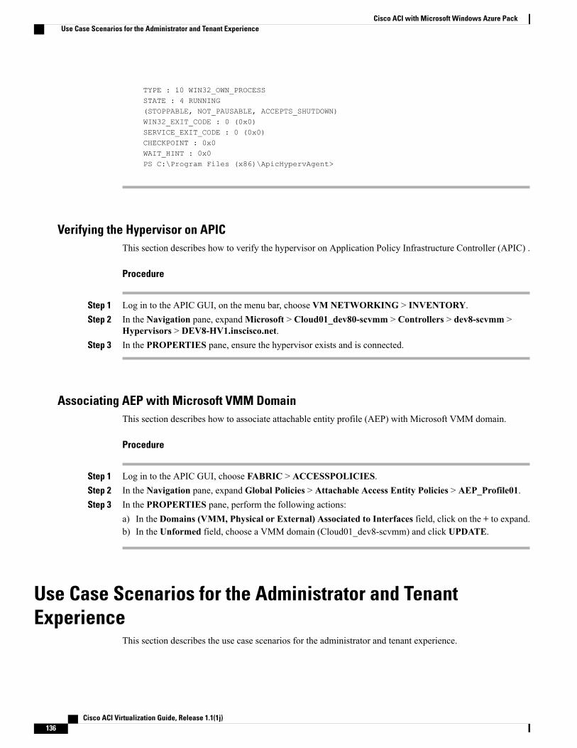
TYPE : 10 WIN32_OWN_PROCESSSTATE : 4 RUNNING(STOPPABLE, NOT_PAUSABLE, ACCEPTS_SHUTDOWN)WIN32_EXIT_CODE : 0 (0x0)SERVICE_EXIT_CODE : 0 (0x0)CHECKPOINT : 0x0WAIT_HINT : 0x0PS C:\Program Files (x86)\ApicHypervAgent>
Verifying the Hypervisor on APICThis section describes how to verify the hypervisor on Application Policy Infrastructure Controller (APIC) .
Procedure
Step 1 Log in to the APIC GUI, on the menu bar, choose VM NETWORKING > INVENTORY.Step 2 In the Navigation pane, expandMicrosoft > Cloud01_dev80-scvmm > Controllers > dev8-scvmm >
Hypervisors > DEV8-HV1.inscisco.net.Step 3 In the PROPERTIES pane, ensure the hypervisor exists and is connected.
Associating AEP with Microsoft VMM DomainThis section describes how to associate attachable entity profile (AEP) with Microsoft VMM domain.
Procedure
Step 1 Log in to the APIC GUI, choose FABRIC > ACCESSPOLICIES.Step 2 In the Navigation pane, expand Global Policies > Attachable Access Entity Policies > AEP_Profile01.Step 3 In the PROPERTIES pane, perform the following actions:
a) In the Domains (VMM, Physical or External) Associated to Interfaces field, click on the + to expand.b) In the Unformed field, choose a VMM domain (Cloud01_dev8-scvmm) and click UPDATE.
Use Case Scenarios for the Administrator and TenantExperience
This section describes the use case scenarios for the administrator and tenant experience.
Cisco ACI Virtualization Guide, Release 1.1(1j)136
Cisco ACI with Microsoft Windows Azure PackUse Case Scenarios for the Administrator and Tenant Experience
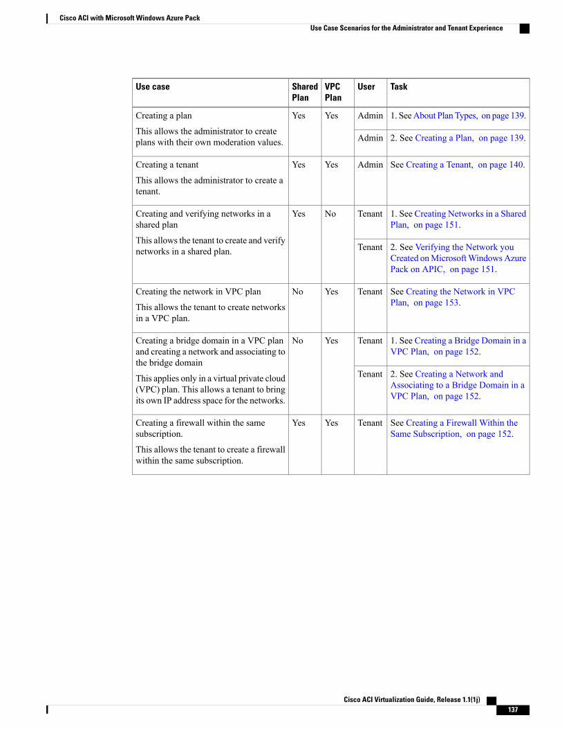
TaskUserVPCPlan
SharedPlan
Use case
1. SeeAbout Plan Types, on page 139.AdminYesYesCreating a plan
This allows the administrator to createplans with their own moderation values. 2. See Creating a Plan, on page 139.Admin
See Creating a Tenant, on page 140.AdminYesYesCreating a tenant
This allows the administrator to create atenant.
1. See Creating Networks in a SharedPlan, on page 151.
TenantNoYesCreating and verifying networks in ashared plan
This allows the tenant to create and verifynetworks in a shared plan. 2. See Verifying the Network you
Created onMicrosoftWindowsAzurePack on APIC, on page 151.
Tenant
See Creating the Network in VPCPlan, on page 153.
TenantYesNoCreating the network in VPC plan
This allows the tenant to create networksin a VPC plan.
1. See Creating a Bridge Domain in aVPC Plan, on page 152.
TenantYesNoCreating a bridge domain in a VPC planand creating a network and associating tothe bridge domain
This applies only in a virtual private cloud(VPC) plan. This allows a tenant to bringits own IP address space for the networks.
2. See Creating a Network andAssociating to a Bridge Domain in aVPC Plan, on page 152.
Tenant
See Creating a Firewall Within theSame Subscription, on page 152.
TenantYesYesCreating a firewall within the samesubscription.
This allows the tenant to create a firewallwithin the same subscription.
Cisco ACI Virtualization Guide, Release 1.1(1j) 137
Cisco ACI with Microsoft Windows Azure PackUse Case Scenarios for the Administrator and Tenant Experience
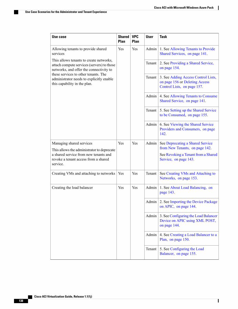
TaskUserVPCPlan
SharedPlan
Use case
1. See Allowing Tenants to ProvideShared Services, on page 141.
AdminYesYesAllowing tenants to provide sharedservices
This allows tenants to create networks,attach compute services (servers) to thosenetworks, and offer the connectivity tothese services to other tenants. Theadministrator needs to explicitly enablethis capability in the plan.
2. See Providing a Shared Service,on page 154.
Tenant
3. See Adding Access Control Lists,on page 156 or Deleting AccessControl Lists, on page 157.
Tenant
4. See Allowing Tenants to ConsumeShared Service, on page 141.
Admin
5. See Setting up the Shared Serviceto be Consumed, on page 155.
Tenant
6. See Viewing the Shared ServiceProviders and Consumers, on page142.
Admin
See Deprecating a Shared Servicefrom New Tenants, on page 142.
See Revoking a Tenant from a SharedService, on page 143.
AdminYesYesManaging shared services
This allows the administrator to deprecatea shared service from new tenants andrevoke a tenant access from a sharedservice.
See Creating VMs and Attaching toNetworks, on page 153.
TenantYesYesCreating VMs and attaching to networks
1. See About Load Balancing, onpage 143.
AdminYesYesCreating the load balancer
2. See Importing the Device Packageon APIC, on page 144.
Admin
3. See Configuring the Load BalancerDevice on APIC using XML POST,on page 144.
Admin
4. See Creating a Load Balancer to aPlan, on page 150.
Admin
5. See Configuring the LoadBalancer, on page 155.
Tenant
Cisco ACI Virtualization Guide, Release 1.1(1j)138
Cisco ACI with Microsoft Windows Azure PackUse Case Scenarios for the Administrator and Tenant Experience
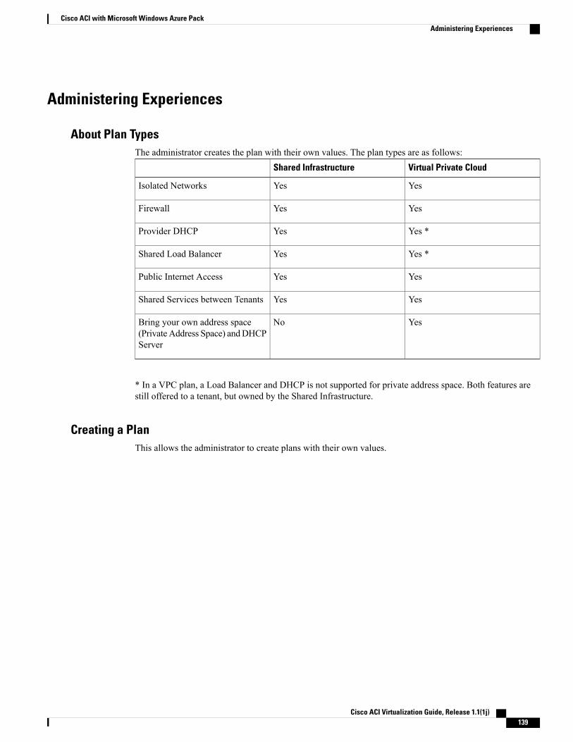
Administering Experiences
About Plan TypesThe administrator creates the plan with their own values. The plan types are as follows:
Virtual Private CloudShared Infrastructure
YesYesIsolated Networks
YesYesFirewall
Yes *YesProvider DHCP
Yes *YesShared Load Balancer
YesYesPublic Internet Access
YesYesShared Services between Tenants
YesNoBring your own address space(PrivateAddress Space) andDHCPServer
* In a VPC plan, a Load Balancer and DHCP is not supported for private address space. Both features arestill offered to a tenant, but owned by the Shared Infrastructure.
Creating a PlanThis allows the administrator to create plans with their own values.
Cisco ACI Virtualization Guide, Release 1.1(1j) 139
Cisco ACI with Microsoft Windows Azure PackAdministering Experiences
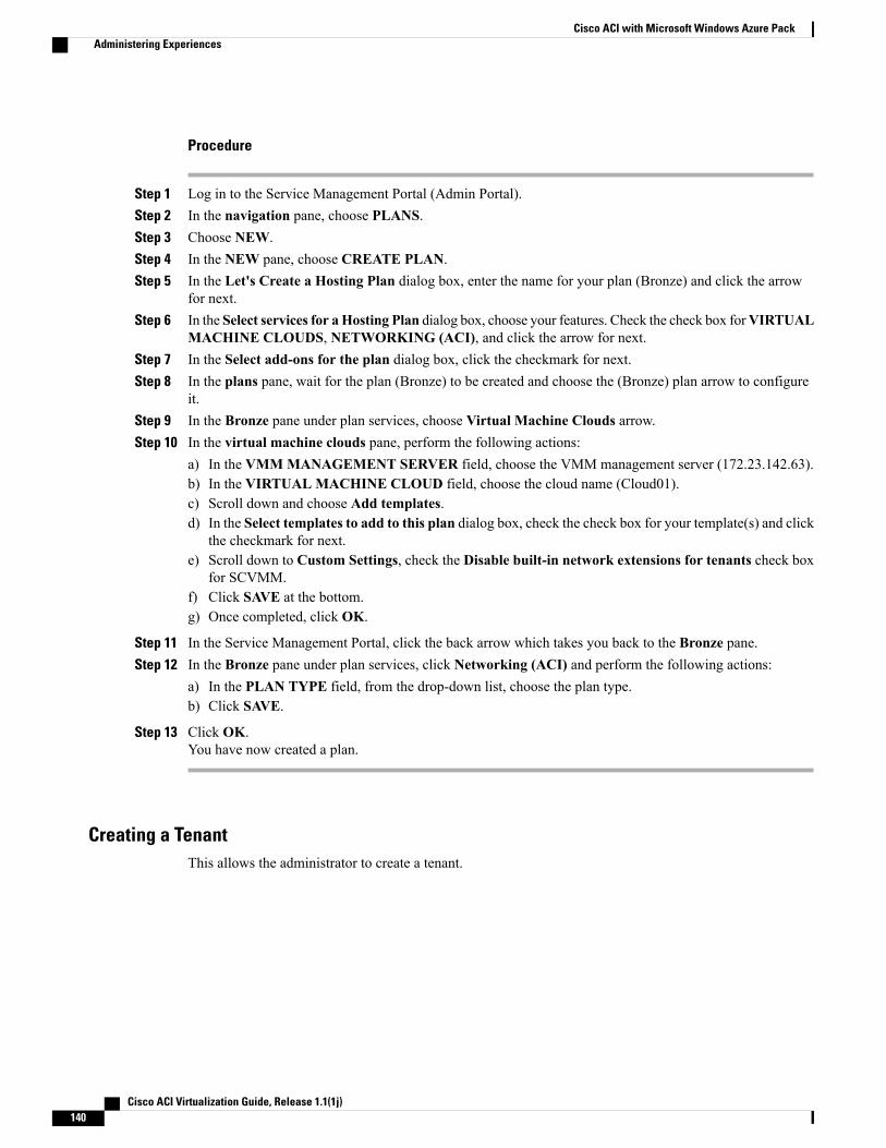
Procedure
Step 1 Log in to the Service Management Portal (Admin Portal).Step 2 In the navigation pane, choose PLANS.Step 3 Choose NEW.Step 4 In the NEW pane, choose CREATE PLAN.Step 5 In the Let's Create a Hosting Plan dialog box, enter the name for your plan (Bronze) and click the arrow
for next.Step 6 In the Select services for aHosting Plan dialog box, choose your features. Check the check box forVIRTUAL
MACHINE CLOUDS, NETWORKING (ACI), and click the arrow for next.Step 7 In the Select add-ons for the plan dialog box, click the checkmark for next.Step 8 In the plans pane, wait for the plan (Bronze) to be created and choose the (Bronze) plan arrow to configure
it.Step 9 In the Bronze pane under plan services, choose Virtual Machine Clouds arrow.Step 10 In the virtual machine clouds pane, perform the following actions:
a) In the VMMMANAGEMENT SERVER field, choose the VMM management server (172.23.142.63).b) In the VIRTUAL MACHINE CLOUD field, choose the cloud name (Cloud01).c) Scroll down and choose Add templates.d) In the Select templates to add to this plan dialog box, check the check box for your template(s) and click
the checkmark for next.e) Scroll down to Custom Settings, check the Disable built-in network extensions for tenants check box
for SCVMM.f) Click SAVE at the bottom.g) Once completed, click OK.
Step 11 In the Service Management Portal, click the back arrow which takes you back to the Bronze pane.Step 12 In the Bronze pane under plan services, click Networking (ACI) and perform the following actions:
a) In the PLAN TYPE field, from the drop-down list, choose the plan type.b) Click SAVE.
Step 13 Click OK.You have now created a plan.
Creating a TenantThis allows the administrator to create a tenant.
Cisco ACI Virtualization Guide, Release 1.1(1j)140
Cisco ACI with Microsoft Windows Azure PackAdministering Experiences
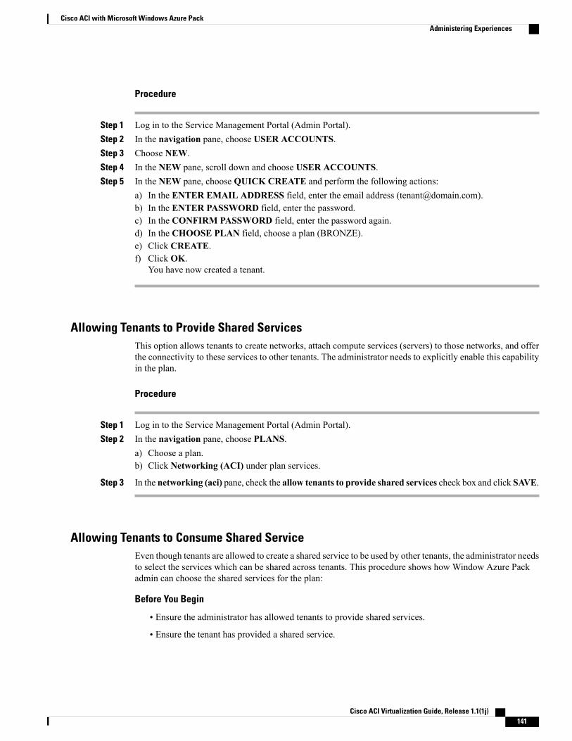
Procedure
Step 1 Log in to the Service Management Portal (Admin Portal).Step 2 In the navigation pane, choose USER ACCOUNTS.Step 3 Choose NEW.Step 4 In the NEW pane, scroll down and choose USER ACCOUNTS.Step 5 In the NEW pane, choose QUICK CREATE and perform the following actions:
a) In the ENTER EMAIL ADDRESS field, enter the email address ([email protected]).b) In the ENTER PASSWORD field, enter the password.c) In the CONFIRM PASSWORD field, enter the password again.d) In the CHOOSE PLAN field, choose a plan (BRONZE).e) Click CREATE.f) Click OK.
You have now created a tenant.
Allowing Tenants to Provide Shared ServicesThis option allows tenants to create networks, attach compute services (servers) to those networks, and offerthe connectivity to these services to other tenants. The administrator needs to explicitly enable this capabilityin the plan.
Procedure
Step 1 Log in to the Service Management Portal (Admin Portal).Step 2 In the navigation pane, choose PLANS.
a) Choose a plan.b) Click Networking (ACI) under plan services.
Step 3 In the networking (aci) pane, check the allow tenants to provide shared services check box and click SAVE.
Allowing Tenants to Consume Shared ServiceEven though tenants are allowed to create a shared service to be used by other tenants, the administrator needsto select the services which can be shared across tenants. This procedure shows how Window Azure Packadmin can choose the shared services for the plan:
Before You Begin
• Ensure the administrator has allowed tenants to provide shared services.
• Ensure the tenant has provided a shared service.
Cisco ACI Virtualization Guide, Release 1.1(1j) 141
Cisco ACI with Microsoft Windows Azure PackAdministering Experiences
Procedure
Step 1 Log in to the Service Management Portal (Admin Portal).Step 2 In the navigation pane, choose PLANS.Step 3 In the plans pane, choose PLANS.
a) Click on the plan (Gold).
Step 4 In the Gold pane, choose Networking (ACI).Step 5 In the networking (aci) pane, check the shared service check box you want to give access to (DBSrv).Step 6 Click SAVE.
Viewing the Shared Service Providers and ConsumersThis allows the administrator to view the shared service providers and consumers.
Before You Begin
• Ensure the administrator has allowed tenants to provide shared services.
• Ensure the tenant has provided a shared service.
• Ensure the administrator has enabled the shared service on a plan.
• Ensure the tenant has set up the shared service to be consumed.
Procedure
Step 1 Log in to the Service Management Portal (Admin Portal).Step 2 In the navigation pane, choose ACI.Step 3 In the ACI pane, choose SHARED SERVICES to view the shared service providers.Step 4 Click on the provider.Step 5 Click INFO to display all the users that are consuming this shared service.
Managing Shared Services
Deprecating a Shared Service from New Tenants
This allows the administrator to deprecate a shared service from new tenants.
Cisco ACI Virtualization Guide, Release 1.1(1j)142
Cisco ACI with Microsoft Windows Azure PackAdministering Experiences
Procedure
Step 1 Log in to the Service Management Portal (Admin Portal).Step 2 In the navigation pane, choose PLANS.Step 3 In the plans pane, choose the plan (Gold).Step 4 In the gold pane, choose Networking (ACI).Step 5 In the networking (aci) pane, uncheck the service from the plan and click SAVE.
You have deprecated the shared service from tenants.
Revoking a Tenant from a Shared Service
This allows the administrator to revoke a tenant from a shared service.
Procedure
Step 1 Log in to the Service Management Portal (Admin Portal).Step 2 In the navigation pane, choose ACI.Step 3 In the aci pane, choose the shared service (DBSrv).Step 4 Click INFO to ensure that the user you want to revoke is present in that shared service.Step 5 In the navigation pane, choose PLANS.Step 6 In the plans pane, choose the plan (Gold).Step 7 In the gold pane, choose Networking (ACI).Step 8 In the networking (aci) pane, uncheck the service from the plan and click SAVE.Step 9 In the navigation pane, choose ACI.Step 10 In the aci pane, choose SHARED SERVICES.Step 11 In the aci pane, choose the shared service (DBSrv) and click INFO.Step 12 In the Revoke Consumers of DBSrv dialog box, check the check box of the user you want to revoke.Step 13 Click the checkmark.
About Load BalancingVLAN and virtual routing and forwarding (VRF) stitching is supported by traditional service insertion models,the Application Policy Infrastructure Controller (APIC) can automate service insertion while acting as a centralpoint of policy control. The APIC policies manage both the network fabric and services appliances. The APICcan configure the network automatically so that traffic flows through the services. The APIC can alsoautomatically configure the service according to the application's requirements, which allows organizationsto automate service insertion and eliminate the challenge of managing the complex techniques of traditionalservice insertion.
See the Cisco APIC Layer 4 to Layer 7 Services Deployment Guide for more information.
Cisco ACI Virtualization Guide, Release 1.1(1j) 143
Cisco ACI with Microsoft Windows Azure PackAdministering Experiences
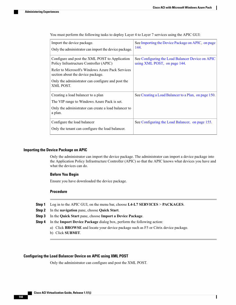
You must perform the following tasks to deploy Layer 4 to Layer 7 services using the APIC GUI:
See Importing the Device Package on APIC, on page144.
Import the device package.
Only the administrator can import the device package.
See Configuring the Load Balancer Device on APICusing XML POST, on page 144.
Configure and post the XML POST to ApplicationPolicy Infrastructure Controller (APIC)
Refer to Microsoft's Windows Azure Pack Servicessection about the device package.
Only the administrator can configure and post theXML POST.
See Creating a Load Balancer to a Plan, on page 150.Creating a load balancer to a plan
The VIP range to Windows Azure Pack is set.
Only the administrator can create a load balancer toa plan.
See Configuring the Load Balancer, on page 155.Configure the load balancer
Only the tenant can configure the load balancer.
Importing the Device Package on APIC
Only the administrator can import the device package. The administrator can import a device package intothe Application Policy Infrastructure Controller (APIC) so that the APIC knows what devices you have andwhat the devices can do.
Before You Begin
Ensure you have downloaded the device package.
Procedure
Step 1 Log in to the APIC GUI, on the menu bar, choose L4-L7 SERVICES > PACKAGES.Step 2 In the navigation pane, choose Quick Start.Step 3 In the Quick Start pane, choose Import a Device Package.Step 4 In the Import Device Package dialog box, perform the following action:
a) Click BROWSE and locate your device package such as F5 or Citrix device package.b) Click SUBMIT.
Configuring the Load Balancer Device on APIC using XML POST
Only the administrator can configure and post the XML POST.
Cisco ACI Virtualization Guide, Release 1.1(1j)144
Cisco ACI with Microsoft Windows Azure PackAdministering Experiences
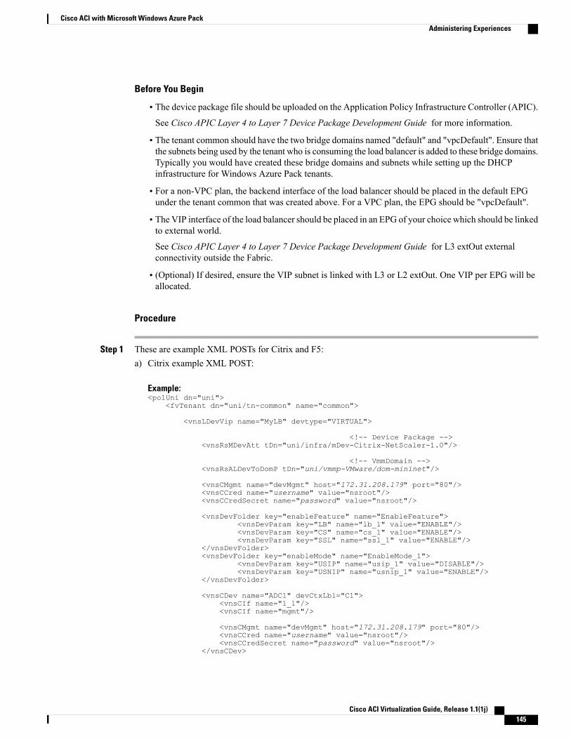
Before You Begin
• The device package file should be uploaded on the Application Policy Infrastructure Controller (APIC).See Cisco APIC Layer 4 to Layer 7 Device Package Development Guide for more information.
• The tenant common should have the two bridge domains named "default" and "vpcDefault". Ensure thatthe subnets being used by the tenant who is consuming the load balancer is added to these bridge domains.Typically you would have created these bridge domains and subnets while setting up the DHCPinfrastructure for Windows Azure Pack tenants.
• For a non-VPC plan, the backend interface of the load balancer should be placed in the default EPGunder the tenant common that was created above. For a VPC plan, the EPG should be "vpcDefault".
• The VIP interface of the load balancer should be placed in an EPG of your choice which should be linkedto external world.
See Cisco APIC Layer 4 to Layer 7 Device Package Development Guide for L3 extOut externalconnectivity outside the Fabric.
• (Optional) If desired, ensure the VIP subnet is linked with L3 or L2 extOut. One VIP per EPG will beallocated.
Procedure
Step 1 These are example XML POSTs for Citrix and F5:a) Citrix example XML POST:
Example:<polUni dn="uni">
<fvTenant dn="uni/tn-common" name="common">
<vnsLDevVip name="MyLB" devtype="VIRTUAL">
<!-- Device Package --><vnsRsMDevAtt tDn="uni/infra/mDev-Citrix-NetScaler-1.0"/>
<!-- VmmDomain --><vnsRsALDevToDomP tDn="uni/vmmp-VMware/dom-mininet"/>
<vnsCMgmt name="devMgmt" host="172.31.208.179" port="80"/><vnsCCred name="username" value="nsroot"/><vnsCCredSecret name="password" value="nsroot"/>
<vnsDevFolder key="enableFeature" name="EnableFeature"><vnsDevParam key="LB" name="lb_1" value="ENABLE"/><vnsDevParam key="CS" name="cs_1" value="ENABLE"/><vnsDevParam key="SSL" name="ssl_1" value="ENABLE"/>
</vnsDevFolder><vnsDevFolder key="enableMode" name="EnableMode_1">
<vnsDevParam key="USIP" name="usip_1" value="DISABLE"/><vnsDevParam key="USNIP" name="usnip_1" value="ENABLE"/>
</vnsDevFolder>
<vnsCDev name="ADC1" devCtxLbl="C1"><vnsCIf name="1_1"/><vnsCIf name="mgmt"/>
<vnsCMgmt name="devMgmt" host="172.31.208.179" port="80"/><vnsCCred name="username" value="nsroot"/><vnsCCredSecret name="password" value="nsroot"/>
</vnsCDev>
Cisco ACI Virtualization Guide, Release 1.1(1j) 145
Cisco ACI with Microsoft Windows Azure PackAdministering Experiences
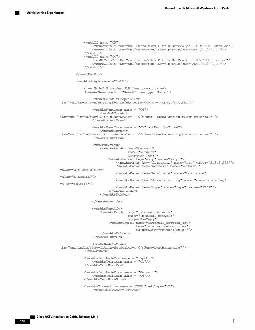
<vnsLIf name="C5"><vnsRsMetaIf tDn="uni/infra/mDev-Citrix-NetScaler-1.0/mIfLbl-outside"/><vnsRsCIfAtt tDn="uni/tn-common/lDevVip-MyLB/cDev-ADC1/cIf-[1_1]"/>
</vnsLIf><vnsLIf name="C4">
<vnsRsMetaIf tDn="uni/infra/mDev-Citrix-NetScaler-1.0/mIfLbl-inside"/><vnsRsCIfAtt tDn="uni/tn-common/lDevVip-MyLB/cDev-ADC1/cIf-[1_1]"/>
</vnsLIf>
</vnsLDevVip>
<vnsAbsGraph name ="MyLB">
<!-- Node2 Provides SLB functionality --><vnsAbsNode name = "Node2" funcType="GoTo" >
<vnsRsDefaultScopeToTermtDn="uni/tn-common/AbsGraph-MyLB/AbsTermNodeProv-Output1/outtmnl"/>
<vnsAbsFuncConn name = "C4"><vnsRsMConnAtt
tDn="uni/infra/mDev-Citrix-NetScaler-1.0/mFunc-LoadBalancing/mConn-external" /></vnsAbsFuncConn>
<vnsAbsFuncConn name = "C5" attNotify="true"><vnsRsMConnAtt
tDn="uni/infra/mDev-Citrix-NetScaler-1.0/mFunc-LoadBalancing/mConn-internal" /></vnsAbsFuncConn>
<vnsAbsDevCfg><vnsAbsFolder key="Network"
name="network"scopedBy="epg">
<vnsAbsFolder key="nsip" name="snip1"><vnsAbsParam key="ipaddress" name="ip1" value="5.5.5.251"/><vnsAbsParam key="netmask" name="netmask1"
value="255.255.255.0"/><vnsAbsParam key="hostroute" name="hostroute"
value="DISABLED"/><vnsAbsParam key="dynamicrouting" name="dynamicrouting"
value="ENABLED"/><vnsAbsParam key="type" name="type" value="SNIP"/>
</vnsAbsFolder></vnsAbsFolder>
</vnsAbsDevCfg>
<vnsAbsFuncCfg><vnsAbsFolder key="internal_network"
name="internal_network"scopedBy="epg">
<vnsAbsCfgRel name="internal_network_key"key="internal_network_key"targetName="network/snip1"/>
</vnsAbsFolder></vnsAbsFuncCfg>
<vnsRsNodeToMFunctDn="uni/infra/mDev-Citrix-NetScaler-1.0/mFunc-LoadBalancing"/>
</vnsAbsNode>
<vnsAbsTermNodeCon name = "Input1"><vnsAbsTermConn name = "C1"/>
</vnsAbsTermNodeCon>
<vnsAbsTermNodeProv name = "Output1"><vnsAbsTermConn name = "C6"/>
</vnsAbsTermNodeProv>
<vnsAbsConnection name = "CON1" adjType="L2"><vnsRsAbsConnectionConns
Cisco ACI Virtualization Guide, Release 1.1(1j)146
Cisco ACI with Microsoft Windows Azure PackAdministering Experiences
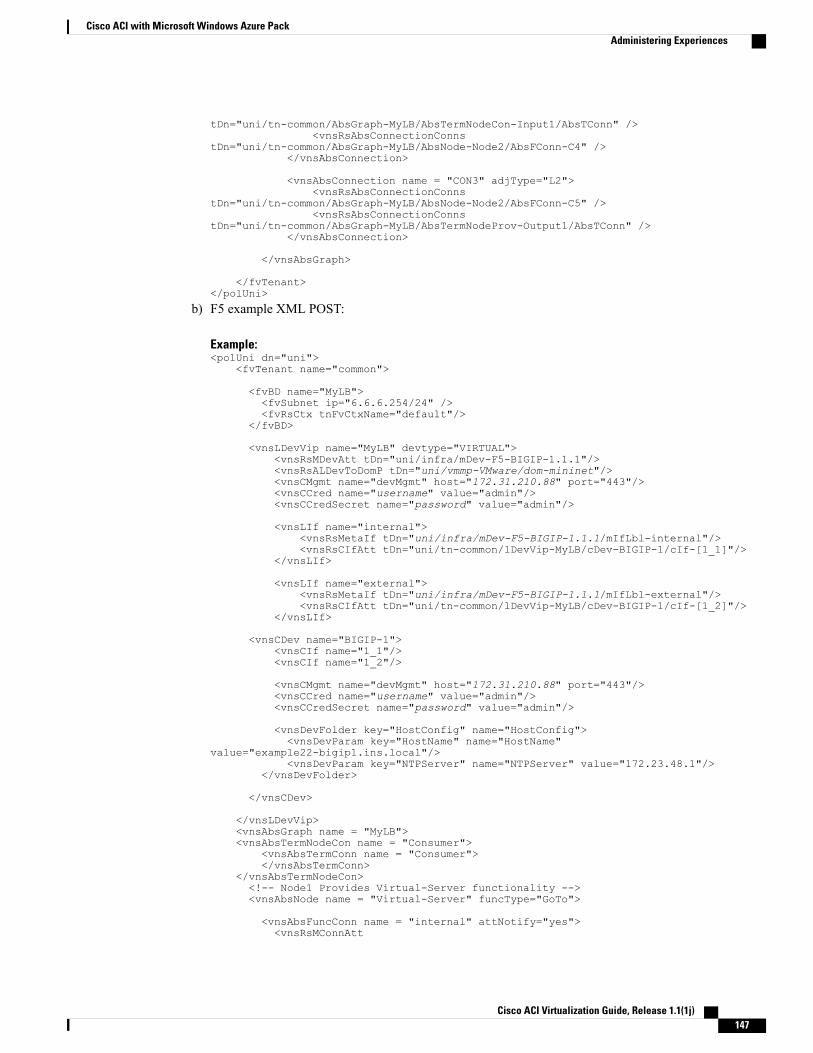
tDn="uni/tn-common/AbsGraph-MyLB/AbsTermNodeCon-Input1/AbsTConn" /><vnsRsAbsConnectionConns
tDn="uni/tn-common/AbsGraph-MyLB/AbsNode-Node2/AbsFConn-C4" /></vnsAbsConnection>
<vnsAbsConnection name = "CON3" adjType="L2"><vnsRsAbsConnectionConns
tDn="uni/tn-common/AbsGraph-MyLB/AbsNode-Node2/AbsFConn-C5" /><vnsRsAbsConnectionConns
tDn="uni/tn-common/AbsGraph-MyLB/AbsTermNodeProv-Output1/AbsTConn" /></vnsAbsConnection>
</vnsAbsGraph>
</fvTenant></polUni>
b) F5 example XML POST:
Example:<polUni dn="uni">
<fvTenant name="common">
<fvBD name="MyLB"><fvSubnet ip="6.6.6.254/24" /><fvRsCtx tnFvCtxName="default"/>
</fvBD>
<vnsLDevVip name="MyLB" devtype="VIRTUAL"><vnsRsMDevAtt tDn="uni/infra/mDev-F5-BIGIP-1.1.1"/><vnsRsALDevToDomP tDn="uni/vmmp-VMware/dom-mininet"/><vnsCMgmt name="devMgmt" host="172.31.210.88" port="443"/><vnsCCred name="username" value="admin"/><vnsCCredSecret name="password" value="admin"/>
<vnsLIf name="internal"><vnsRsMetaIf tDn="uni/infra/mDev-F5-BIGIP-1.1.1/mIfLbl-internal"/><vnsRsCIfAtt tDn="uni/tn-common/lDevVip-MyLB/cDev-BIGIP-1/cIf-[1_1]"/>
</vnsLIf>
<vnsLIf name="external"><vnsRsMetaIf tDn="uni/infra/mDev-F5-BIGIP-1.1.1/mIfLbl-external"/><vnsRsCIfAtt tDn="uni/tn-common/lDevVip-MyLB/cDev-BIGIP-1/cIf-[1_2]"/>
</vnsLIf>
<vnsCDev name="BIGIP-1"><vnsCIf name="1_1"/><vnsCIf name="1_2"/>
<vnsCMgmt name="devMgmt" host="172.31.210.88" port="443"/><vnsCCred name="username" value="admin"/><vnsCCredSecret name="password" value="admin"/>
<vnsDevFolder key="HostConfig" name="HostConfig"><vnsDevParam key="HostName" name="HostName"
value="example22-bigip1.ins.local"/><vnsDevParam key="NTPServer" name="NTPServer" value="172.23.48.1"/>
</vnsDevFolder>
</vnsCDev>
</vnsLDevVip><vnsAbsGraph name = "MyLB"><vnsAbsTermNodeCon name = "Consumer">
<vnsAbsTermConn name = "Consumer"></vnsAbsTermConn>
</vnsAbsTermNodeCon><!-- Node1 Provides Virtual-Server functionality --><vnsAbsNode name = "Virtual-Server" funcType="GoTo">
<vnsAbsFuncConn name = "internal" attNotify="yes"><vnsRsMConnAtt
Cisco ACI Virtualization Guide, Release 1.1(1j) 147
Cisco ACI with Microsoft Windows Azure PackAdministering Experiences
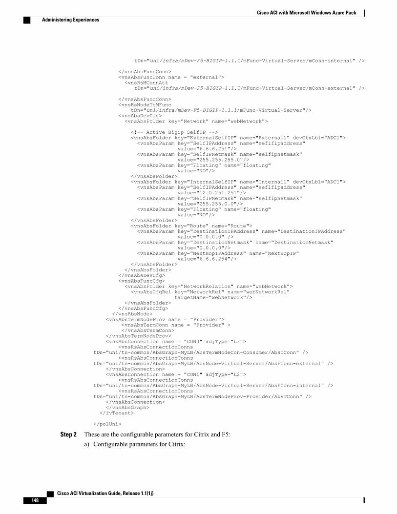
tDn="uni/infra/mDev-F5-BIGIP-1.1.1/mFunc-Virtual-Server/mConn-internal" />
</vnsAbsFuncConn><vnsAbsFuncConn name = "external"><vnsRsMConnAtt
tDn="uni/infra/mDev-F5-BIGIP-1.1.1/mFunc-Virtual-Server/mConn-external" />
</vnsAbsFuncConn><vnsRsNodeToMFunc
tDn="uni/infra/mDev-F5-BIGIP-1.1.1/mFunc-Virtual-Server"/><vnsAbsDevCfg><vnsAbsFolder key="Network" name="webNetwork">
<!-- Active Bigip SelfIP --><vnsAbsFolder key="ExternalSelfIP" name="External1" devCtxLbl="ADC1"><vnsAbsParam key="SelfIPAddress" name="seflfipaddress"
value="6.6.6.251"/><vnsAbsParam key="SelfIPNetmask" name="selfipnetmask"
value="255.255.255.0"/><vnsAbsParam key="Floating" name="floating"
value="NO"/></vnsAbsFolder><vnsAbsFolder key="InternalSelfIP" name="Internal1" devCtxLbl="ADC1"><vnsAbsParam key="SelfIPAddress" name="seflfipaddress"
value="12.0.251.251"/><vnsAbsParam key="SelfIPNetmask" name="selfipnetmask"
value="255.255.0.0"/><vnsAbsParam key="Floating" name="floating"
value="NO"/></vnsAbsFolder><vnsAbsFolder key="Route" name="Route"><vnsAbsParam key="DestinationIPAddress" name="DestinationIPAddress"
value="0.0.0.0" /><vnsAbsParam key="DestinationNetmask" name="DestinationNetmask"
value="0.0.0.0"/><vnsAbsParam key="NextHopIPAddress" name="NextHopIP"
value="6.6.6.254"/></vnsAbsFolder>
</vnsAbsFolder></vnsAbsDevCfg><vnsAbsFuncCfg><vnsAbsFolder key="NetworkRelation" name="webNetwork"><vnsAbsCfgRel key="NetworkRel" name="webNetworkRel"
targetName="webNetwork"/></vnsAbsFolder>
</vnsAbsFuncCfg></vnsAbsNode>
<vnsAbsTermNodeProv name = "Provider"><vnsAbsTermConn name = "Provider" ></vnsAbsTermConn>
</vnsAbsTermNodeProv><vnsAbsConnection name = "CON3" adjType="L3">
<vnsRsAbsConnectionConnstDn="uni/tn-common/AbsGraph-MyLB/AbsTermNodeCon-Consumer/AbsTConn" />
<vnsRsAbsConnectionConnstDn="uni/tn-common/AbsGraph-MyLB/AbsNode-Virtual-Server/AbsFConn-external" />
</vnsAbsConnection><vnsAbsConnection name = "CON1" adjType="L2">
<vnsRsAbsConnectionConnstDn="uni/tn-common/AbsGraph-MyLB/AbsNode-Virtual-Server/AbsFConn-internal" />
<vnsRsAbsConnectionConnstDn="uni/tn-common/AbsGraph-MyLB/AbsTermNodeProv-Provider/AbsTConn" />
</vnsAbsConnection></vnsAbsGraph>
</fvTenant>
</polUni>
Step 2 These are the configurable parameters for Citrix and F5:a) Configurable parameters for Citrix:
Cisco ACI Virtualization Guide, Release 1.1(1j)148
Cisco ACI with Microsoft Windows Azure PackAdministering Experiences
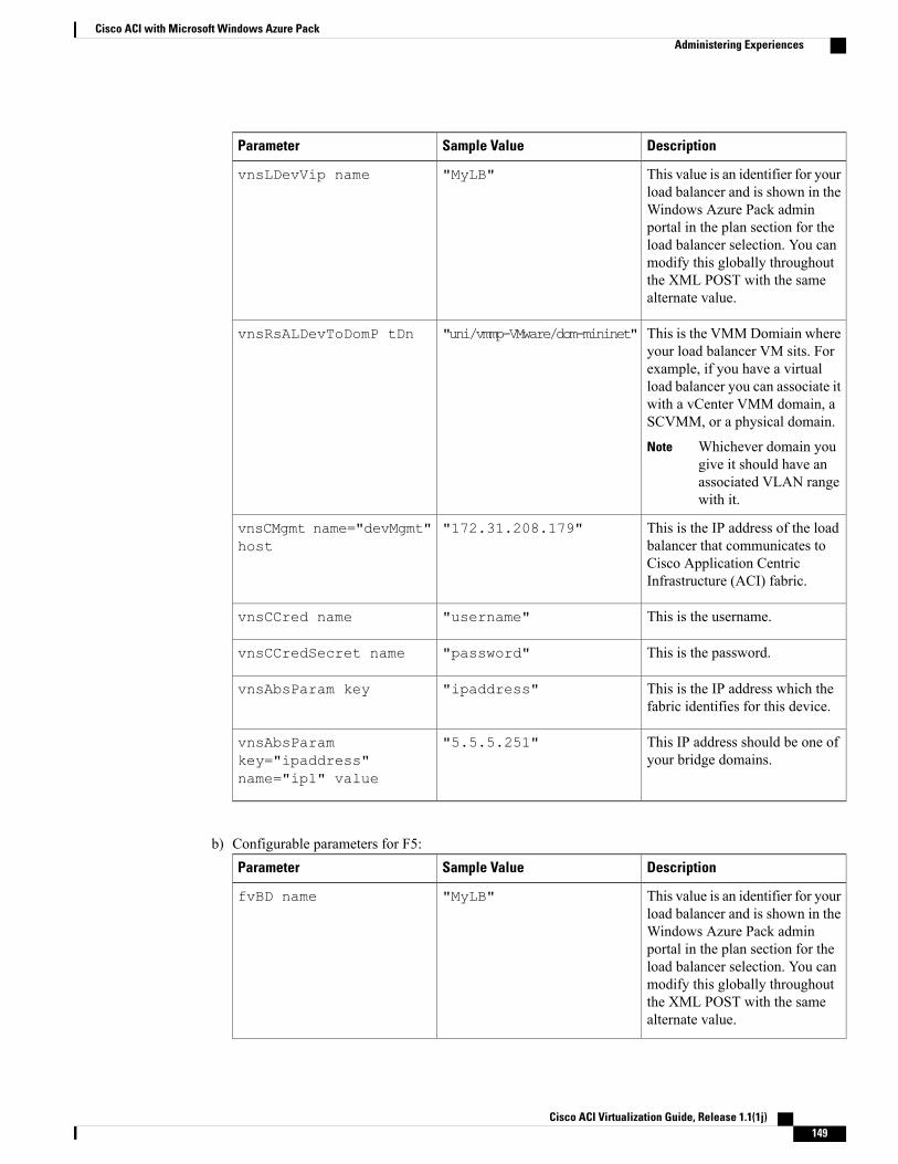
DescriptionSample ValueParameter
This value is an identifier for yourload balancer and is shown in theWindows Azure Pack adminportal in the plan section for theload balancer selection. You canmodify this globally throughoutthe XML POST with the samealternate value.
"MyLB"vnsLDevVip name
This is the VMMDomiain whereyour load balancer VM sits. Forexample, if you have a virtualload balancer you can associate itwith a vCenter VMM domain, aSCVMM, or a physical domain.
Whichever domain yougive it should have anassociated VLAN rangewith it.
Note
"uni/vmmp-VMware/dom-mininet"vnsRsALDevToDomP tDn
This is the IP address of the loadbalancer that communicates toCisco Application CentricInfrastructure (ACI) fabric.
"172.31.208.179"vnsCMgmt name="devMgmt"host
This is the username."username"vnsCCred name
This is the password."password"vnsCCredSecret name
This is the IP address which thefabric identifies for this device.
"ipaddress"vnsAbsParam key
This IP address should be one ofyour bridge domains.
"5.5.5.251"vnsAbsParamkey="ipaddress"name="ip1" value
b) Configurable parameters for F5:DescriptionSample ValueParameter
This value is an identifier for yourload balancer and is shown in theWindows Azure Pack adminportal in the plan section for theload balancer selection. You canmodify this globally throughoutthe XML POST with the samealternate value.
"MyLB"fvBD name
Cisco ACI Virtualization Guide, Release 1.1(1j) 149
Cisco ACI with Microsoft Windows Azure PackAdministering Experiences
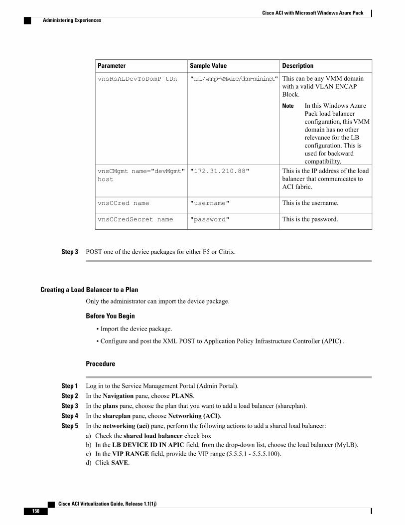
DescriptionSample ValueParameter
This can be any VMM domainwith a valid VLAN ENCAPBlock.
In this Windows AzurePack load balancerconfiguration, this VMMdomain has no otherrelevance for the LBconfiguration. This isused for backwardcompatibility.
Note
"uni/vmmp-VMware/dom-mininet"vnsRsALDevToDomP tDn
This is the IP address of the loadbalancer that communicates toACI fabric.
"172.31.210.88"vnsCMgmt name="devMgmt"host
This is the username."username"vnsCCred name
This is the password."password"vnsCCredSecret name
Step 3 POST one of the device packages for either F5 or Citrix.
Creating a Load Balancer to a Plan
Only the administrator can import the device package.
Before You Begin
• Import the device package.
• Configure and post the XML POST to Application Policy Infrastructure Controller (APIC) .
Procedure
Step 1 Log in to the Service Management Portal (Admin Portal).Step 2 In the Navigation pane, choose PLANS.Step 3 In the plans pane, choose the plan that you want to add a load balancer (shareplan).Step 4 In the shareplan pane, choose Networking (ACI).Step 5 In the networking (aci) pane, perform the following actions to add a shared load balancer:
a) Check the shared load balancer check boxb) In the LB DEVICE ID IN APIC field, from the drop-down list, choose the load balancer (MyLB).c) In the VIP RANGE field, provide the VIP range (5.5.5.1 - 5.5.5.100).d) Click SAVE.
Cisco ACI Virtualization Guide, Release 1.1(1j)150
Cisco ACI with Microsoft Windows Azure PackAdministering Experiences
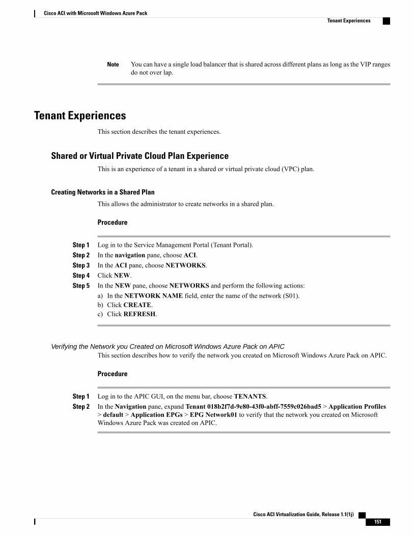
You can have a single load balancer that is shared across different plans as long as the VIP rangesdo not over lap.
Note
Tenant ExperiencesThis section describes the tenant experiences.
Shared or Virtual Private Cloud Plan ExperienceThis is an experience of a tenant in a shared or virtual private cloud (VPC) plan.
Creating Networks in a Shared Plan
This allows the administrator to create networks in a shared plan.
Procedure
Step 1 Log in to the Service Management Portal (Tenant Portal).Step 2 In the navigation pane, choose ACI.Step 3 In the ACI pane, choose NETWORKS.Step 4 Click NEW.Step 5 In the NEW pane, choose NETWORKS and perform the following actions:
a) In the NETWORK NAME field, enter the name of the network (S01).b) Click CREATE.c) Click REFRESH.
Verifying the Network you Created on Microsoft Windows Azure Pack on APICThis section describes how to verify the network you created on Microsoft Windows Azure Pack on APIC.
Procedure
Step 1 Log in to the APIC GUI, on the menu bar, choose TENANTS.Step 2 In the Navigation pane, expand Tenant 018b2f7d-9e80-43f0-abff-7559c026bad5 > Application Profiles
> default > Application EPGs > EPG Network01 to verify that the network you created on MicrosoftWindows Azure Pack was created on APIC.
Cisco ACI Virtualization Guide, Release 1.1(1j) 151
Cisco ACI with Microsoft Windows Azure PackTenant Experiences
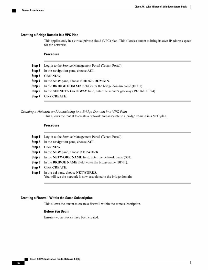
Creating a Bridge Domain in a VPC Plan
This applies only in a virtual private cloud (VPC) plan. This allows a tenant to bring its own IP address spacefor the networks.
Procedure
Step 1 Log in to the Service Management Portal (Tenant Portal).Step 2 In the navigation pane, choose ACI.Step 3 Click NEW.Step 4 In the NEW pane, choose BRIDGE DOMAIN.Step 5 In the BRIDGE DOMAIN field, enter the bridge domain name (BD01).Step 6 In the SUBNET'S GATEWAY field, enter the subnet's gateway (192.168.1.1/24).Step 7 Click CREATE.
Creating a Network and Associating to a Bridge Domain in a VPC PlanThis allows the tenant to create a network and associate to a bridge domain in a VPC plan.
Procedure
Step 1 Log in to the Service Management Portal (Tenant Portal).Step 2 In the navigation pane, choose ACI.Step 3 Click NEW.Step 4 In the NEW pane, choose NETWORK.Step 5 In the NETWORK NAME field, enter the network name (S01).Step 6 In the BRIDGE NAME field, enter the bridge name (BD01).Step 7 Click CREATE.Step 8 In the aci pane, choose NETWORKS.
You will see the network is now associated to the bridge domain.
Creating a Firewall Within the Same Subscription
This allows the tenant to create a firewall within the same subscription.
Before You Begin
Ensure two networks have been created.
Cisco ACI Virtualization Guide, Release 1.1(1j)152
Cisco ACI with Microsoft Windows Azure PackTenant Experiences
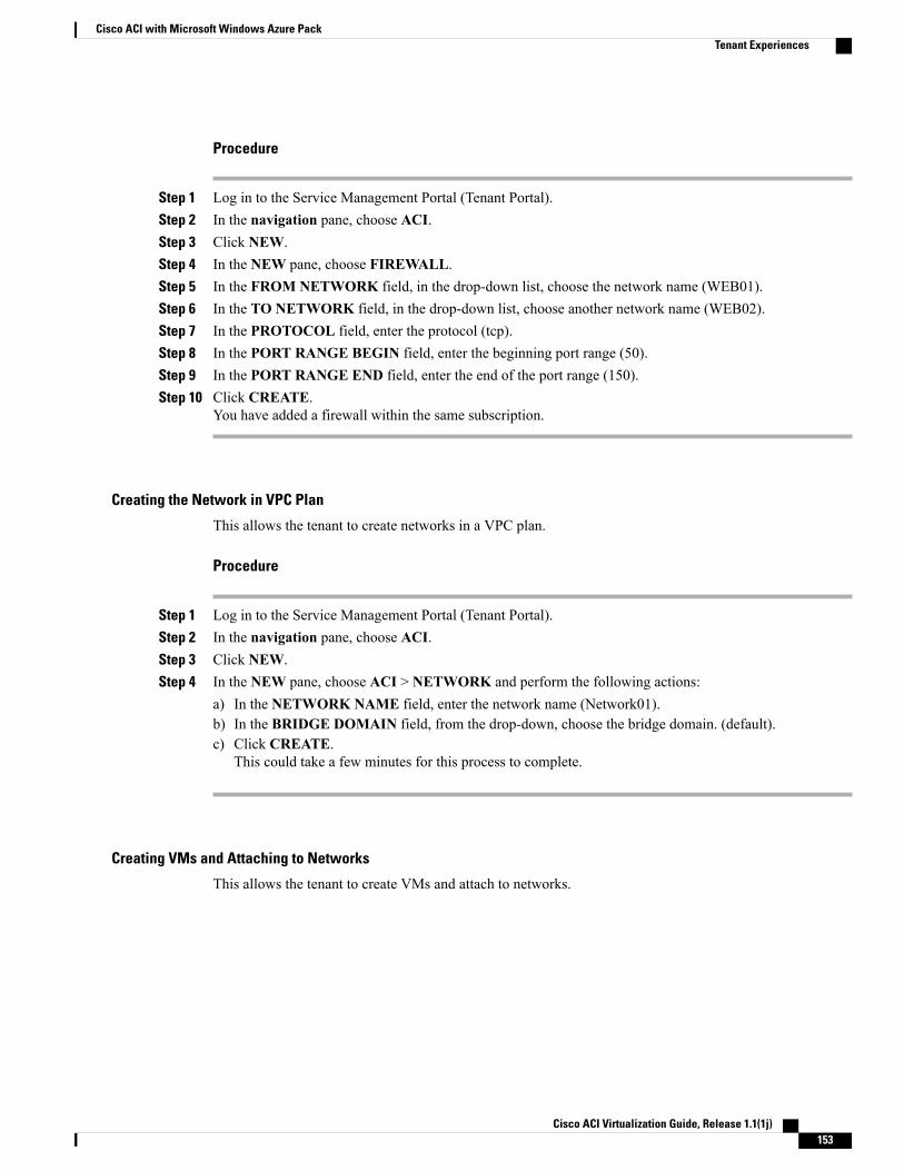
Procedure
Step 1 Log in to the Service Management Portal (Tenant Portal).Step 2 In the navigation pane, choose ACI.Step 3 Click NEW.Step 4 In the NEW pane, choose FIREWALL.Step 5 In the FROM NETWORK field, in the drop-down list, choose the network name (WEB01).Step 6 In the TO NETWORK field, in the drop-down list, choose another network name (WEB02).Step 7 In the PROTOCOL field, enter the protocol (tcp).Step 8 In the PORT RANGE BEGIN field, enter the beginning port range (50).Step 9 In the PORT RANGE END field, enter the end of the port range (150).Step 10 Click CREATE.
You have added a firewall within the same subscription.
Creating the Network in VPC Plan
This allows the tenant to create networks in a VPC plan.
Procedure
Step 1 Log in to the Service Management Portal (Tenant Portal).Step 2 In the navigation pane, choose ACI.Step 3 Click NEW.Step 4 In the NEW pane, choose ACI > NETWORK and perform the following actions:
a) In the NETWORK NAME field, enter the network name (Network01).b) In the BRIDGE DOMAIN field, from the drop-down, choose the bridge domain. (default).c) Click CREATE.
This could take a few minutes for this process to complete.
Creating VMs and Attaching to Networks
This allows the tenant to create VMs and attach to networks.
Cisco ACI Virtualization Guide, Release 1.1(1j) 153
Cisco ACI with Microsoft Windows Azure PackTenant Experiences
Procedure
Step 1 Log in to the Service Management Portal (Tenant Portal).Step 2 In the navigation pane, choose ACI.Step 3 Click NEW.Step 4 In the NEW pane, choose STANDALONE VIRTUAL MACHINE > FROM GALLERY.Step 5 In the Virtual Machine Configuration dialog box, choose your configuration (LinuxCentOS).Step 6 Click the arrow for next.Step 7 In the Portal Virtual Machine Settings dialog box, perform the following actions:
a) In the NAME field, enter the VM name (SVM01).b) In the ADMINISTRATOR ACCOUNT field, root displays.c) In the NEW PASSWORD field, enter a new password.d) In the CONFIRM field, re-enter the password to confirm.e) Click the arrow for next.
Step 8 In the Provide Virtual Machine Hardware Information dialog box, perform the following actions:a) In the NETWORKADAPTER 1 field, from the drop-down list, choose the network adapter to associate
and compute (6C6DB302-aObb-4d49-a22c-151f2fbad0e9|default|S01).b) Click the checkmark.
Step 9 In the navigation pane, choose Virtual Machines to check the status of the VM (SVM01).
Providing a Shared Service
This allows the tenant to provide a shared service.
Before You Begin
Ensure the administrator has allowed tenants to provide shared services.
Procedure
Step 1 Log in to the Service Management Portal (Tenant Portal).Step 2 In the navigation pane, choose ACI.Step 3 In the ACI pane, choose SHARED SERVICE.Step 4 In the SHARED SERVICES dialog box, perform the following actions:
a) In theACTION field, from the drop-down list, choosePROVIDEASHAREDSERVICECONTRACT.b) In the NETWORK field, from the drop-down list, choose the network (WEB01).c) In the SERVICE NAME field, enter the service name (DBSrv).d) In the DESCRIPTION field, enter the description.e) In the PROTOCOL field, enter the protocol (tcp).f) In the PORT RANGE BEGIN field, enter the beginning port range (139).g) In the PORT RANGE END field, enter the end port range (139).
Cisco ACI Virtualization Guide, Release 1.1(1j)154
Cisco ACI with Microsoft Windows Azure PackTenant Experiences
h) Click the checkmark.
Setting up the Shared Service to be Consumed
This allows the tenant to setup the shared service to be consumed.
Before You Begin
• Ensure the administrator has allowed tenants to provide shared services.
• Ensure the tenant has provided a shared service.
• Ensure the administrator has enabled the shared service on a plan.
Procedure
Step 1 Log in to the Service Management Portal (Tenant Portal).Step 2 In the navigation pane, choose ACI > SHARED SERVICE.Step 3 In the SHARED SERVICE dialog box, perform the following actions:
a) In the Network field, choose the network (V1).b) In the Consumed Services field, check the service check box (DBSrv).c) Check the checkmark.
Step 4 In the aci pane, choose SHARED SERVICES to check the consumer of the plan.
Configuring the Load Balancer
This allows the tenant to configure the load balancer.
Before You Begin
• Ensure the administrator imported the device package.
• Ensure the administrator configured and posted the XML POST to Application Policy InfrastructureController (APIC).
• Ensure the administrator added the load balancer to a plan.
Cisco ACI Virtualization Guide, Release 1.1(1j) 155
Cisco ACI with Microsoft Windows Azure PackTenant Experiences
Procedure
Step 1 Log in to the Service Management Portal (Tenant Portal).Step 2 In the navigation pane, choose ACI.Step 3 Click NEW.Step 4 In the NEW pane, choose LOAD BALANCER.Step 5 In the NETWORK NAME field, enter the network name (WEB01).Step 6 In the PORT field, enter the port (80).Step 7 In the PROTOCOL field, enter the protocol (tcp).Step 8 Click CREATE.Step 9 In the ACI pane, choose LOAD BALANCER to check the network, virtual server, application server, port,
and protocol of the load balancer.The bridge domain should have the following subnets:
• SNIP subnet
• Host subnet
• VIP subnet
If you want the VIP subnet, it should be linked with L3 or L2 extOut.
Adding Access Control Lists
This allows the tenant to add access control lists (ACLs) to the shared service.
Procedure
Step 1 Log in to the Service Management Portal (Tenant Portal).Step 2 In the navigation pane, choose ACI.Step 3 In the aci pane, choose SHARED SERVICES.Step 4 In the aci pane, choose a shared service to which you want to add more ACLs (DBSrv).Step 5 Click +ACL to add ACLs.Step 6 In the Add ACL for DBSrv dialog box, perform the following actions:
a) In the PROTOCOL field, enter the protocol (tcp).b) In the PORT NUMBER BEGIN field, enter the beginning port number (301).c) In the PORT NUMBER END field, enter the end port number (400).d) Click the checkmark.
Cisco ACI Virtualization Guide, Release 1.1(1j)156
Cisco ACI with Microsoft Windows Azure PackTenant Experiences
Deleting Access Control Lists
This allows the tenant to delete access control lists (ACLs) from the shared service.
Procedure
Step 1 Log in to the Service Management Portal (Tenant Portal).Step 2 In the navigation pane, choose ACI.Step 3 In the aci pane, perform the following actions:
a) Choose SHARED SERVICES.b) Choose a shared service from which you want to delete ACLs (DBSrv).c) Click Trash ACL to delete ACLs.
Step 4 In the Delete ACL from DBSrv dialog box, check the ACLs check box that you want to delete and click thecheckmark.
Troubleshooting Cisco ACI with Microsoft Windows Azure Pack
Troubleshooting as an Admin
Procedure
Windows Azure Pack Administrator can look at all networks deployed by tenants in the admin portal. In casethere is an issue, use the APIC GUI to look for any faults on the following objects:a) VMM domainb) Tenant and EPG corresponding to the Windows Azure Pack tenant networks.
Troubleshooting as a TenantIf there is an error message, provide the error message along with the description of the workflow and actionto your Administrator.
Troubleshooting the EPG Configuration IssueIf during the lifetime of the endpoint group (EPG), the VLAN ID of the EPG changes on the APIC thenSCVMM needs to update the VLAN configuration on all virtual machines for the new setting to take effect.
Procedure
To perform this operation, run the following PowerShell commands on the SCVMM server:
Cisco ACI Virtualization Guide, Release 1.1(1j) 157
Cisco ACI with Microsoft Windows Azure PackTroubleshooting Cisco ACI with Microsoft Windows Azure Pack
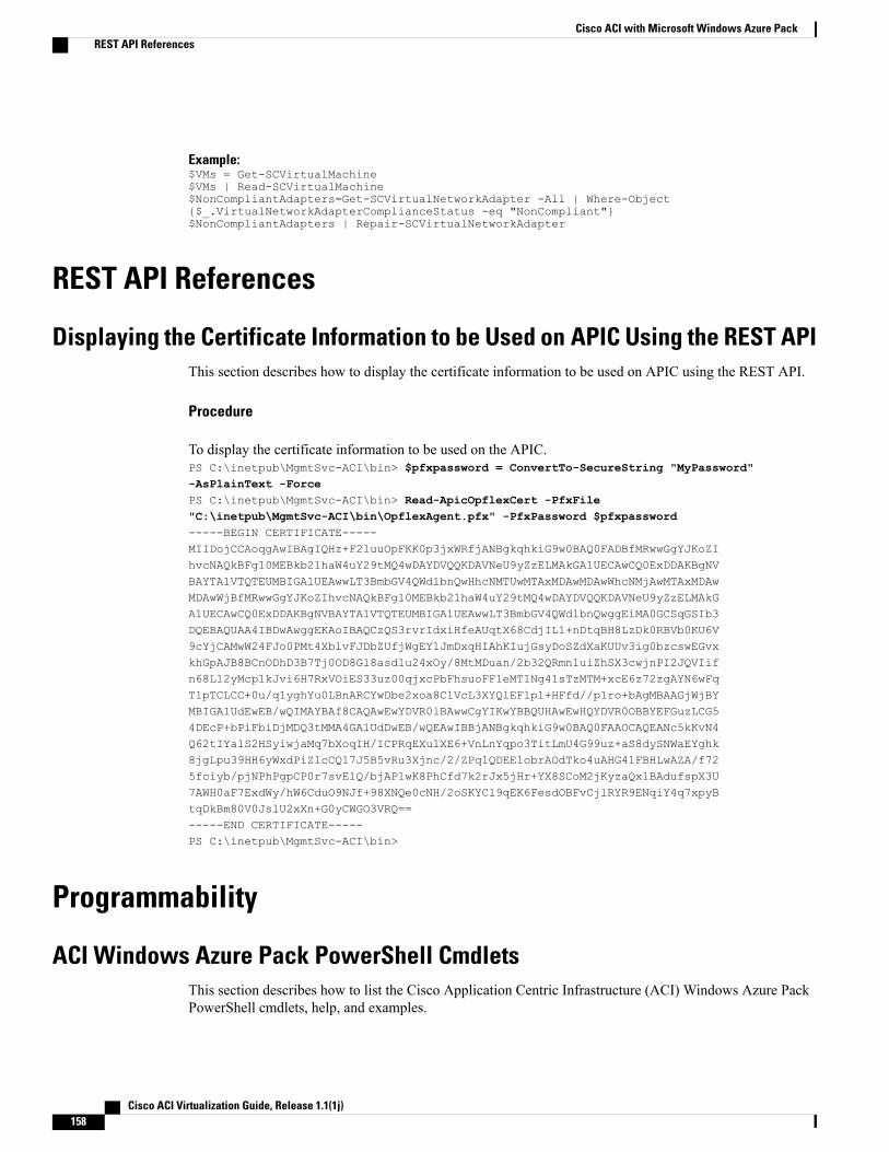
Example:$VMs = Get-SCVirtualMachine$VMs | Read-SCVirtualMachine$NonCompliantAdapters=Get-SCVirtualNetworkAdapter -All | Where-Object{$_.VirtualNetworkAdapterComplianceStatus -eq "NonCompliant"}$NonCompliantAdapters | Repair-SCVirtualNetworkAdapter
REST API References
Displaying the Certificate Information to be Used on APIC Using the REST APIThis section describes how to display the certificate information to be used on APIC using the REST API.
Procedure
To display the certificate information to be used on the APIC.PS C:\inetpub\MgmtSvc-ACI\bin> $pfxpassword = ConvertTo-SecureString "MyPassword"-AsPlainText -ForcePS C:\inetpub\MgmtSvc-ACI\bin> Read-ApicOpflexCert -PfxFile"C:\inetpub\MgmtSvc-ACI\bin\OpflexAgent.pfx" -PfxPassword $pfxpassword-----BEGIN CERTIFICATE-----MIIDojCCAoqgAwIBAgIQHz+F2luuOpFKK0p3jxWRfjANBgkqhkiG9w0BAQ0FADBfMRwwGgYJKoZIhvcNAQkBFg10MEBkb21haW4uY29tMQ4wDAYDVQQKDAVNeU9yZzELMAkGA1UECAwCQ0ExDDAKBgNVBAYTA1VTQTEUMBIGA1UEAwwLT3BmbGV4QWdlbnQwHhcNMTUwMTAxMDAwMDAwWhcNMjAwMTAxMDAwMDAwWjBfMRwwGgYJKoZIhvcNAQkBFg10MEBkb21haW4uY29tMQ4wDAYDVQQKDAVNeU9yZzELMAkGA1UECAwCQ0ExDDAKBgNVBAYTA1VTQTEUMBIGA1UEAwwLT3BmbGV4QWdlbnQwggEiMA0GCSqGSIb3DQEBAQUAA4IBDwAwggEKAoIBAQCzQS3rvrIdxiHfeAUqtX68CdjIL1+nDtqBH8LzDk0RBVb0KU6V9cYjCAMwW24FJo0PMt4XblvFJDbZUfjWgEY1JmDxqHIAhKIujGsyDoSZdXaKUUv3ig0bzcswEGvxkhGpAJB8BCnODhD3B7Tj0OD8Gl8asd1u24xOy/8MtMDuan/2b32QRmn1uiZhSX3cwjnPI2JQVIifn68L12yMcp1kJvi6H7RxVOiES33uz00qjxcPbFhsuoFF1eMT1Ng41sTzMTM+xcE6z72zgAYN6wFqT1pTCLCC+0u/q1yghYu0LBnARCYwDbe2xoa8ClVcL3XYQlEFlp1+HFfd//p1ro+bAgMBAAGjWjBYMBIGA1UdEwEB/wQIMAYBAf8CAQAwEwYDVR0lBAwwCgYIKwYBBQUHAwEwHQYDVR0OBBYEFGuzLCG54DEcP+bPiFbiDjMDQ3tMMA4GA1UdDwEB/wQEAwIBBjANBgkqhkiG9w0BAQ0FAAOCAQEANc5kKvN4Q62tIYa1S2HSyiwjaMq7bXoqIH/ICPRqEXu1XE6+VnLnYqpo3TitLmU4G99uz+aS8dySNWaEYghk8jgLpu39HH6yWxdPiZlcCQ17J5B5vRu3Xjnc/2/ZPqlQDEElobrAOdTko4uAHG4lFBHLwAZA/f725fciyb/pjNPhPgpCP0r7svElQ/bjAP1wK8PhCfd7k2rJx5jHr+YX8SCoM2jKyzaQx1BAdufspX3U7AWH0aF7ExdWy/hW6CduO9NJf+98XNQe0cNH/2oSKYCl9qEK6FesdOBFvCjlRYR9ENqiY4q7xpyBtqDkBm80V0JslU2xXn+G0yCWGO3VRQ==-----END CERTIFICATE-----PS C:\inetpub\MgmtSvc-ACI\bin>
Programmability
ACI Windows Azure Pack PowerShell CmdletsThis section describes how to list the Cisco Application Centric Infrastructure (ACI) Windows Azure PackPowerShell cmdlets, help, and examples.
Cisco ACI Virtualization Guide, Release 1.1(1j)158
Cisco ACI with Microsoft Windows Azure PackREST API References
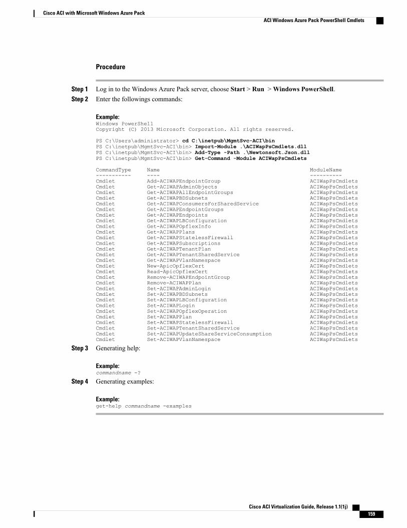
Procedure
Step 1 Log in to the Windows Azure Pack server, choose Start > Run >Windows PowerShell.Step 2 Enter the followings commands:
Example:Windows PowerShellCopyright (C) 2013 Microsoft Corporation. All rights reserved.
PS C:\Users\administrator> cd C:\inetpub\MgmtSvc-ACI\binPS C:\inetpub\MgmtSvc-ACI\bin> Import-Module .\ACIWapPsCmdlets.dllPS C:\inetpub\MgmtSvc-ACI\bin> Add-Type -Path .\Newtonsoft.Json.dllPS C:\inetpub\MgmtSvc-ACI\bin> Get-Command -Module ACIWapPsCmdlets
CommandType Name ModuleName----------- ---- ----------Cmdlet Add-ACIWAPEndpointGroup ACIWapPsCmdletsCmdlet Get-ACIWAPAdminObjects ACIWapPsCmdletsCmdlet Get-ACIWAPAllEndpointGroups ACIWapPsCmdletsCmdlet Get-ACIWAPBDSubnets ACIWapPsCmdletsCmdlet Get-ACIWAPConsumersForSharedService ACIWapPsCmdletsCmdlet Get-ACIWAPEndpointGroups ACIWapPsCmdletsCmdlet Get-ACIWAPEndpoints ACIWapPsCmdletsCmdlet Get-ACIWAPLBConfiguration ACIWapPsCmdletsCmdlet Get-ACIWAPOpflexInfo ACIWapPsCmdletsCmdlet Get-ACIWAPPlans ACIWapPsCmdletsCmdlet Get-ACIWAPStatelessFirewall ACIWapPsCmdletsCmdlet Get-ACIWAPSubscriptions ACIWapPsCmdletsCmdlet Get-ACIWAPTenantPlan ACIWapPsCmdletsCmdlet Get-ACIWAPTenantSharedService ACIWapPsCmdletsCmdlet Get-ACIWAPVlanNamespace ACIWapPsCmdletsCmdlet New-ApicOpflexCert ACIWapPsCmdletsCmdlet Read-ApicOpflexCert ACIWapPsCmdletsCmdlet Remove-ACIWAPEndpointGroup ACIWapPsCmdletsCmdlet Remove-ACIWAPPlan ACIWapPsCmdletsCmdlet Set-ACIWAPAdminLogin ACIWapPsCmdletsCmdlet Set-ACIWAPBDSubnets ACIWapPsCmdletsCmdlet Set-ACIWAPLBConfiguration ACIWapPsCmdletsCmdlet Set-ACIWAPLogin ACIWapPsCmdletsCmdlet Set-ACIWAPOpflexOperation ACIWapPsCmdletsCmdlet Set-ACIWAPPlan ACIWapPsCmdletsCmdlet Set-ACIWAPStatelessFirewall ACIWapPsCmdletsCmdlet Set-ACIWAPTenantSharedService ACIWapPsCmdletsCmdlet Set-ACIWAPUpdateShareServiceConsumption ACIWapPsCmdletsCmdlet Set-ACIWAPVlanNamespace ACIWapPsCmdlets
Step 3 Generating help:
Example:commandname -?
Step 4 Generating examples:
Example:get-help commandname -examples
Cisco ACI Virtualization Guide, Release 1.1(1j) 159
Cisco ACI with Microsoft Windows Azure PackACI Windows Azure Pack PowerShell Cmdlets
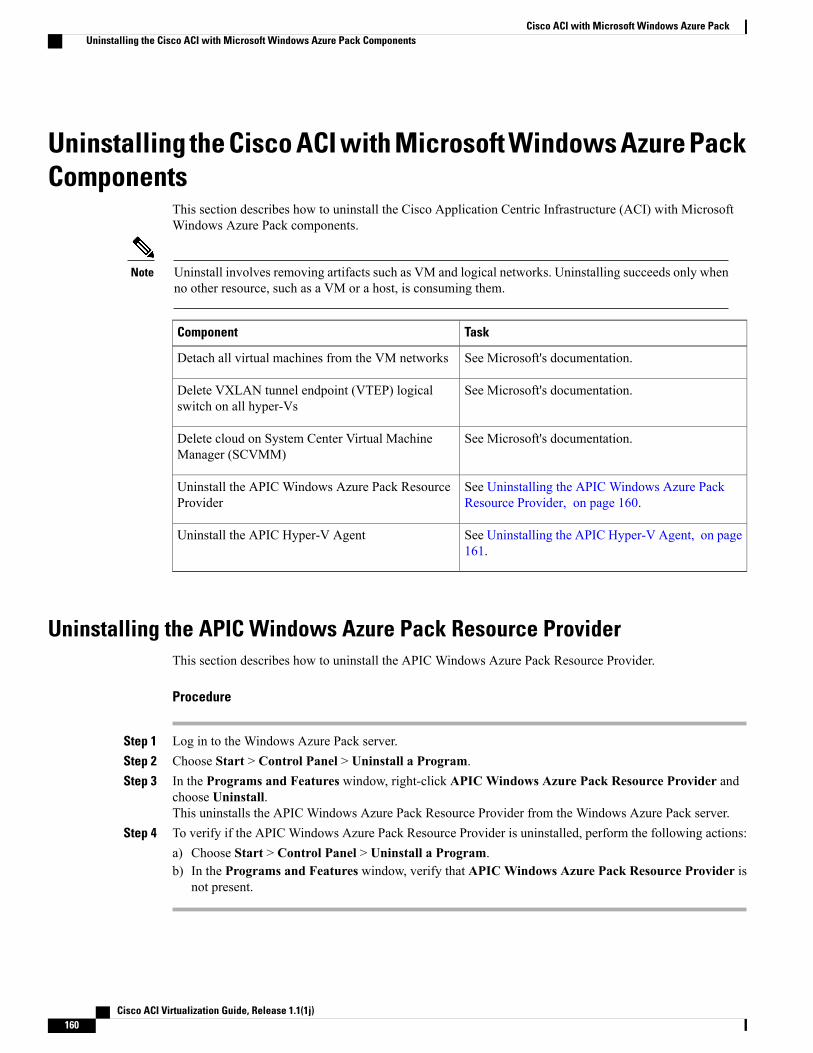
Uninstalling the Cisco ACI with Microsoft Windows Azure PackComponents
This section describes how to uninstall the Cisco Application Centric Infrastructure (ACI) with MicrosoftWindows Azure Pack components.
Uninstall involves removing artifacts such as VM and logical networks. Uninstalling succeeds only whenno other resource, such as a VM or a host, is consuming them.
Note
TaskComponent
See Microsoft's documentation.Detach all virtual machines from the VM networks
See Microsoft's documentation.Delete VXLAN tunnel endpoint (VTEP) logicalswitch on all hyper-Vs
See Microsoft's documentation.Delete cloud on System Center Virtual MachineManager (SCVMM)
See Uninstalling the APIC Windows Azure PackResource Provider, on page 160.
Uninstall the APIC Windows Azure Pack ResourceProvider
See Uninstalling the APIC Hyper-V Agent, on page161.
Uninstall the APIC Hyper-V Agent
Uninstalling the APIC Windows Azure Pack Resource ProviderThis section describes how to uninstall the APIC Windows Azure Pack Resource Provider.
Procedure
Step 1 Log in to the Windows Azure Pack server.Step 2 Choose Start > Control Panel > Uninstall a Program.Step 3 In the Programs and Features window, right-click APIC Windows Azure Pack Resource Provider and
choose Uninstall.This uninstalls the APIC Windows Azure Pack Resource Provider from the Windows Azure Pack server.
Step 4 To verify if the APIC Windows Azure Pack Resource Provider is uninstalled, perform the following actions:a) Choose Start > Control Panel > Uninstall a Program.b) In the Programs and Features window, verify that APIC Windows Azure Pack Resource Provider is
not present.
Cisco ACI Virtualization Guide, Release 1.1(1j)160
Cisco ACI with Microsoft Windows Azure PackUninstalling the Cisco ACI with Microsoft Windows Azure Pack Components
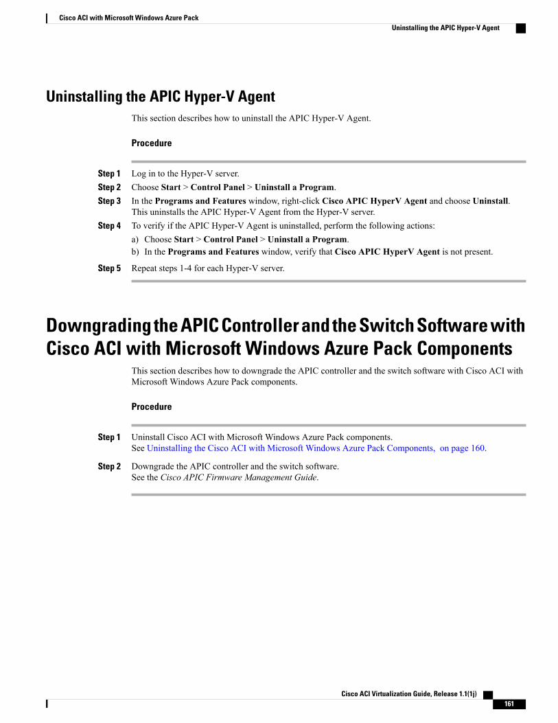
Uninstalling the APIC Hyper-V AgentThis section describes how to uninstall the APIC Hyper-V Agent.
Procedure
Step 1 Log in to the Hyper-V server.Step 2 Choose Start > Control Panel > Uninstall a Program.Step 3 In the Programs and Features window, right-click Cisco APIC HyperV Agent and choose Uninstall.
This uninstalls the APIC Hyper-V Agent from the Hyper-V server.Step 4 To verify if the APIC Hyper-V Agent is uninstalled, perform the following actions:
a) Choose Start > Control Panel > Uninstall a Program.b) In the Programs and Features window, verify that Cisco APIC HyperV Agent is not present.
Step 5 Repeat steps 1-4 for each Hyper-V server.
Downgrading the APIC Controller and the Switch Software withCisco ACI with Microsoft Windows Azure Pack Components
This section describes how to downgrade the APIC controller and the switch software with Cisco ACI withMicrosoft Windows Azure Pack components.
Procedure
Step 1 Uninstall Cisco ACI with Microsoft Windows Azure Pack components.See Uninstalling the Cisco ACI with Microsoft Windows Azure Pack Components, on page 160.
Step 2 Downgrade the APIC controller and the switch software.See the Cisco APIC Firmware Management Guide.
Cisco ACI Virtualization Guide, Release 1.1(1j) 161
Cisco ACI with Microsoft Windows Azure PackUninstalling the APIC Hyper-V Agent

Cisco ACI Virtualization Guide, Release 1.1(1j)162
Cisco ACI with Microsoft Windows Azure PackDowngrading the APIC Controller and the Switch Software with Cisco ACI with Microsoft Windows Azure PackComponents