circulators mv-4/ mv-6/ mv-12/ mv-26 mw-4/ mw-6/ … · concerning the operation of your unit or...
TRANSCRIPT
19511402.doc
CirculatorsMV-4/ MV-6/ MV-12/ MV-26
MW-4/ MW-6/ MW-12/ MW-26MW-Z
!
1.951.1402BE2 01/03

Operating controls and functional elements
2
Congratulations!You have made an excellent choice.JULABO thanks you for the trust you have placed in us.This operating manual has been designed to help you gain an understanding of theprinciples of operating and possibilities of our circulators. For optimum utilizationof all functions, we recommend that you thoroughly study this manual prior tobeginning operation.
Safety WarningsTake care your unit is operated only by qualified persons.Make sure you read and understand all instructions and safety precautions listed inthis manual before installing or operating your unit. If you have any questionsconcerning the operation of your unit or the information in this manual, contactJULABO.Performance of installation, operation, or maintenance procedures other than thosedescribed in this manual may result in a hazardous situation and may void themanufacturer's warranty.Transport the unit with care. Sudden jolts or drops may cause damages in theinterior of the unit.Observe all warning labels.Never remove warning labels.Never operate damaged or leaking equipment.Never operate the unit without bath fluid in the bath.Always turn off the unit and disconnect the mains cable from the power sourcebefore performing any service or maintenance procedures, or before moving theunit.Always empty the bath before moving the unit.Never operate equipment with damaged mains power cables.Refer service and repairs to a qualified technician.
In addition to the safety warnings listed above, warnings are postedthroughout the manual. These warnings are designated by anexclamation mark inside an equilateral triangle. Read and followthese important instructions. Failure to observe these instructions canresult in permanent damage to the unit, significant property damage,personal injury or death.

MV / MW
3
TABLE OF CONTENTS
1. .Operating controls and functional elements....................................................... 42. .Quality Management System............................................................................... 63. .Unpacking and checking...................................................................................... 64. .Description ............................................................................................................ 65. .Preparations.......................................................................................................... 7
5.1. Installation.................................................................................................. 7
5.2. Bath liquids and tubing............................................................................. 7
5.3. Filling / draining......................................................................................... 8
5.4. Countercooling.......................................................................................... 9
5.5. Temperature application to external systems......................................10
5.6. Adjusting the pump flow.........................................................................12
6. .Operating procedures ........................................................................................136.1. Power connection...................................................................................13
6.2. Switching on / Start - Stop.....................................................................13
6.3. Setting the temperatures .......................................................................15
6.4. Warning functions ...................................................................................16
6.5. Setting the safety temperature (with shutdown function) ....................17
7. .Troubleshooting guide / Error messages.........................................................188. .Safety recommendations ...................................................................................209. .ATC - Absolute Temperature Calibration.........................................................2110. Configuration for counter-cooling ...............................................................2211. Electrical connections..................................................................................2312. Remote control .............................................................................................24
12.1. Setup for remote control........................................................................24
12.2. Communication with a PC or a superordinated data system............25
12.3. List of commands...................................................................................26
12.4. Status messages....................................................................................26
12.5. Error messages......................................................................................27
13. Cleaning the unit...........................................................................................2814. Maintenance .................................................................................................2815. Technical specifications ..............................................................................2916. EC Declaration of Conformity.....................................................................3117. Warranty conditions .....................................................................................32
Operating controls and functional elements
4
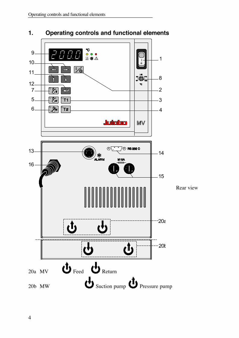
1. Operating controls and functional elements
!
5
6
7
9
10
11
12
1
2
3
4
8
14
15
16
20a
13
20b
Rear view
20a MV Feed Return
20b MW Suction pump Pressure pump

MV / MW
5
1 Mains power switch, illuminated
2 Start / stop key
3 Working temperature T1
4 Working temperature T2
5 High temperature warning limit
6 Low temperature warning limit
7 Safety temperature
8 Adjustable excess temperature protection
(safety temperature)
9 MULTI-DISPLAY (LED) temperature indication
10 Cursors left/right
11 Edit keys (increase/decrease setting)
12 Enter key (store)
Indicator light - Alarm
Indicator light - Cooling (not operational)
Indicator light - Heating
13 Connector: alarm output
1415
69 RS232C interface15 Mains fuses, fuse holders16 Mains power cable with plug20a Pump connectors on MV20b Pump connectors on MW
Quality Management System
6
2. Quality Management SystemThe JULABO Quality Management System:Development, production and distribution of temperatureapplication instruments for research and industries conform tothe requirements according to DIN EN ISO 9001:1994-08.Certificate Registration No. QA 051004008.
3. Unpacking and checkingUnpack the circulator and accessories and check for damages incurred duringtransit. These should be reported to the responsible carrier, railway, or postalauthority, and a request for a damage report should be made. These instructionsmust be followed fully for us to guarantee our full support of your claim forprotecting against loss from concealed damage. The form required for filing such aclaim will be provided by the carrier.
4. DescriptionThe JULABO circulators are suitable for temperature application to liquids in abath tank.The main functional elements are the heater, circulation pump, and controlelectronics. An electronic proportional temperature control (PID characteristic)adapts the heat supplied to the thermal requirements of the bath.Setting is rapid and simple using the keypad with its easy to learn symbols. Keypadis splash-proof, easily cleaned and ergonomically designed.The microprocessor technology allows four temperature values to be stored andindicated on the MULTI-DISPLAY (LED): working temperatures T1 and T2, highand low temperature warning limits.The safety value for excess temperature protection, a safety installationindependent from the control circuit, is adjustable on the front and visible on theMULTI-DISPLAY (LED).The RS232C port permits modern process engineering without additional interface,directly on-line, from the circulator to your application equipment.The circulator conforms to the safety requirements specified by DIN 12 876(safety class III), as well as DIN 58 966, and the guideline for first voltage rangeEN 61010.

MV / MW
7
5. Preparations
5.1. Installation
!Heating circulators Place the circulator in an upright position.
Bridge mounted circulator Place the bath tank in an upright position. Adjust the bridge to width of the bath tank and
place it on the bath tank.Bridge is extendable from 310 mm to 660 mm.
5.2. Bath liquids and tubing
Operation with flammable bath liquids permitted.
Recommended bath liquids:Bath liquids Temperature range Flash point fire pointThermal M +50 °C ... 170 °C >275 °C >320 °CThermal H +50 °C ... 250 °C >280 °C >350 °Cdeionized water 5 °C bis 80 °C
ATTENTION: The maximum permissible viscosity is 30 mm2 x s-1.
No liability for use of other bath liquids!
Order No. Bath liquid8 940 1008 940 1018 940 1028 940 103
Thermal MThermal MThermal HThermal H
10 liters container5 liters container
10 liters container5 liters container

Preparations
8
Recommended tubing:
Temperature rangeCR tubingViton tubing
-20 °C to +120 °C-50 °C to +200 °C
5.3. Filling / drainingFillingTake care that no liquid enters the interior of thecirculator.• Recommended maximum filling level with water as
bath liquid: 25 mm below the tank rim• Recommended maximum filling level with bath oils:
40 mm below the tank rim
ATTENTION: the volume of bath oils will increase due tothermal expansion when the bath temperature rises.
Exercise CAUTION when emptying hot bath liquids!
Draining• Press the mains switch to turn the circulator off.• Place the heating circulator near the rim of the table.
Use a suitable vessel as recipient for the bath liquid.• A drain plug is located on the front of the bath tank
that is unscrewed to drain the bath.
• Remove the bridge mounted circulator from the bathtank.
• Empty the bath tank.
Store and dispose the used bath liquid accordingto the laws for environmental protection.
MV / MW
9
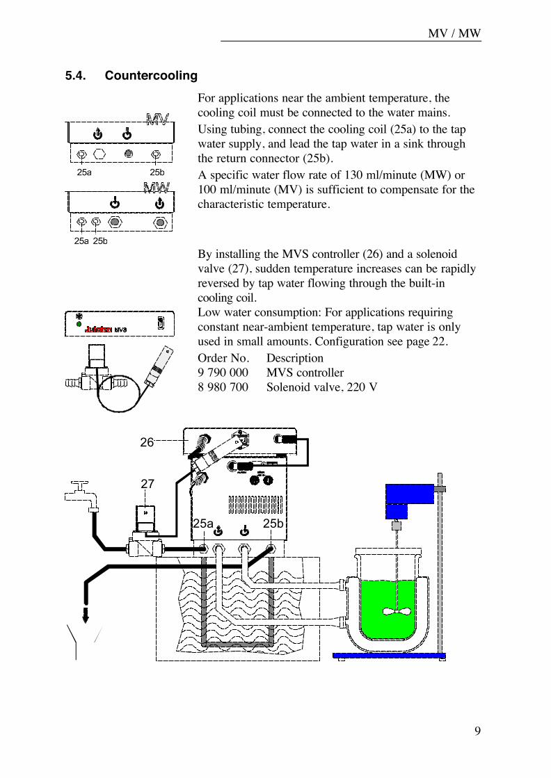
5.4. Countercooling
25a 25b
25b25a
For applications near the ambient temperature, thecooling coil must be connected to the water mains.Using tubing, connect the cooling coil (25a) to the tapwater supply, and lead the tap water in a sink throughthe return connector (25b).A specific water flow rate of 130 ml/minute (MW) or100 ml/minute (MV) is sufficient to compensate for thecharacteristic temperature.
By installing the MVS controller (26) and a solenoidvalve (27), sudden temperature increases can be rapidlyreversed by tap water flowing through the built-incooling coil.Low water consumption: For applications requiringconstant near-ambient temperature, tap water is onlyused in small amounts. Configuration see page 22.Order No. Description9 790 000 MVS controller8 980 700 Solenoid valve, 220 V
26
27
25b25a
Preparations
10
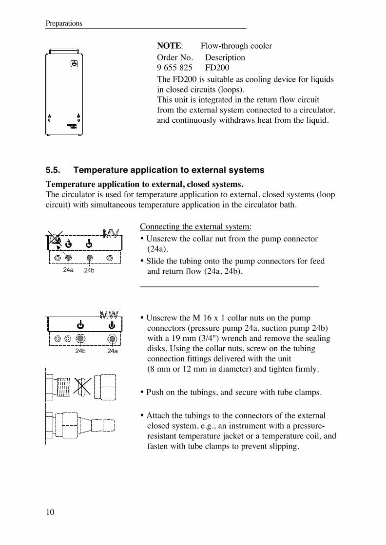
NOTE: Flow-through coolerOrder No. Description9 655 825 FD200The FD200 is suitable as cooling device for liquidsin closed circuits (loops).This unit is integrated in the return flow circuitfrom the external system connected to a circulator,and continuously withdraws heat from the liquid.
5.5. Temperature application to external systemsTemperature application to external, closed systems.The circulator is used for temperature application to external, closed systems (loopcircuit) with simultaneous temperature application in the circulator bath.
24a 24b
Connecting the external system:• Unscrew the collar nut from the pump connector
(24a).• Slide the tubing onto the pump connectors for feed
and return flow (24a, 24b).
24a24b
Unscrew the M 16 x 1 collar nuts on the pumpconnectors (pressure pump 24a, suction pump 24b)with a 19 mm (3/4") wrench and remove the sealingdisks. Using the collar nuts, screw on the tubingconnection fittings delivered with the unit(8 mm or 12 mm in diameter) and tighten firmly.
Push on the tubings, and secure with tube clamps.
Attach the tubings to the connectors of the externalclosed system, e.g., an instrument with a pressure-resistant temperature jacket or a temperature coil, andfasten with tube clamps to prevent slipping.

MV / MW
11
Temperature application to external, open systems
K
S
D
H
S = Suction pump connectionD = Pressure pump connectionK = FloatH = Height adjustment
MW circulators are equipped with both a pressure andsuction pump for external temperature application inopen systems.Connections are to be made as described on page 10.
Differing flow rates of the pressure and suction pumpsshould be compensated. To maintain a constant liquidlevel, the JULABO "D+S" Level Adapter isrecommended for the external bath tank. The flowrate of the pressure pump (24a) will be then regulatedby a built-in float device. The liquid level may bechanged by a height adjustment on the "D+S" LevelAdapter.
Order No. 8 970 410 "D+S" Level Adapter
Note: If the liquid levels in the circulator bath and the external systemare at different heights, overflowing must be prevented after thepower has been turned off. Close off both connection tubings withstandard pinchcocks or shut-off valves
Order No. Description8 970 456 Shut-off valve (suitable up to +90 °C)8 970 457 Shut-off valve (suitable up to +250 °C)
Fasten tubing to prevent slipping.

Preparations
12
5.6. Adjusting the pump flow
1
2
The pump flow is pre-adjusted inthe factory and can be modified tosuit user requirements.
• Using a screwdriver turn the screw (1)anti-clockwise by 360 °.
• Using flat pliers turn the marking of theslide (2) to the desired position.
• Tighten the screw.
Examples:
Internal applications in the bathA 100 % internal bath circulation
(for large bath tanks)B Reduced internal bath circulation
(for smooth surface of bath liquid)
External/internal applicationsC 40 % external discharge,
60 % internal circulation(for large bath tanks)
D 80 % external discharge,20 % internal circulation(for small bath tanks)

MV / MW
13
6. Operating procedures
6.1. Power connection
Connect the unit only to a grounded mains power socket!We disclaim all liability for damage caused by incorrect linevoltages!
Check to make sure that the line voltage matches thesupply voltage specified on the identification plate.Deviations of ±10 % are permissible.
6.2. Switching on / Start - StopSwitching on:Turn on the mains power switch.The unit performs a self-test. All segments of the 4-digitMULTI-DISPLAY (LED) and all indicator lights willilluminate.Then the software version (example: n 1.2) appears.The display "OFF" or "r OFF" indicates the unit isready to operate (standby mode).The circulator enters the operating mode activatedbefore switching the circulator off:keypad control mode (manual operation) orremote control mode (operation via personalcomputer).
Start: Press the start/stop key.
- The MULTI-DISPLAY (LED) indicates the actualbath temperature. (example: 21.0 °C)
- An illuminated indicator light in the "T1" or "T2"key indicates the activated working temperature.
Stop: Press the start/stop key.
The MULTI-DISPLAY (LED) indicates the message"OFF".
Operating procedures
14
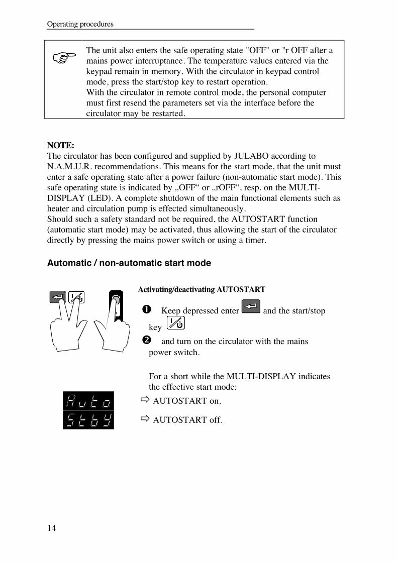
The unit also enters the safe operating state "OFF" or "r OFF after amains power interruptance. The temperature values entered via thekeypad remain in memory. With the circulator in keypad controlmode, press the start/stop key to restart operation.With the circulator in remote control mode, the personal computermust first resend the parameters set via the interface before thecirculator may be restarted.
NOTE:The circulator has been configured and supplied by JULABO according toN.A.M.U.R. recommendations. This means for the start mode, that the unit mustenter a safe operating state after a power failure (non-automatic start mode). Thissafe operating state is indicated by „OFF“ or „rOFF“, resp. on the MULTI-DISPLAY (LED). A complete shutdown of the main functional elements such asheater and circulation pump is effected simultaneously.Should such a safety standard not be required, the AUTOSTART function(automatic start mode) may be activated, thus allowing the start of the circulatordirectly by pressing the mains power switch or using a timer.
Automatic / non-automatic start mode
Activating/deactivating AUTOSTART
Keep depressed enter and the start/stop
key and turn on the circulator with the mains
power switch.
For a short while the MULTI-DISPLAY indicatesthe effective start mode:
AUTOSTART on.
AUTOSTART off.
MV / MW
15
Warning: For supervised or unsupervised operation with the AUTOSTARTfunction, avoid any hazardous situation to persons or property.The circulator does no longer conform to N.A.M.U.R. recommend-ations.Take care you fully observe the safety and warning functions of thecirculator.
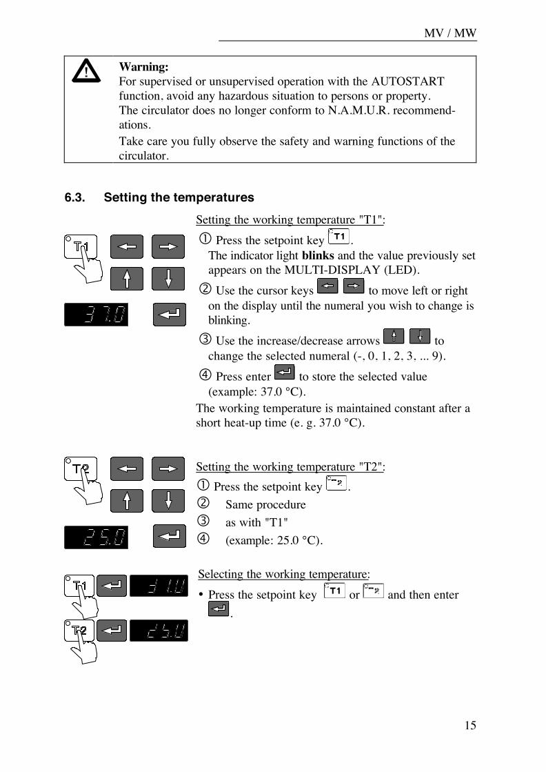
6.3. Setting the temperaturesSetting the working temperature "T1": Press the setpoint key .
The indicator light blinks and the value previously setappears on the MULTI-DISPLAY (LED).
Use the cursor keys to move left or righton the display until the numeral you wish to change isblinking.
Use the increase/decrease arrows tochange the selected numeral (-, 0, 1, 2, 3, ... 9).
Press enter to store the selected value(example: 37.0 °C).
The working temperature is maintained constant after ashort heat-up time (e. g. 37.0 °C).
Setting the working temperature "T2": Press the setpoint key . Same procedure as with "T1" (example: 25.0 °C).
Selecting the working temperature:• Press the setpoint key or and then enter
.
Operating procedures
16
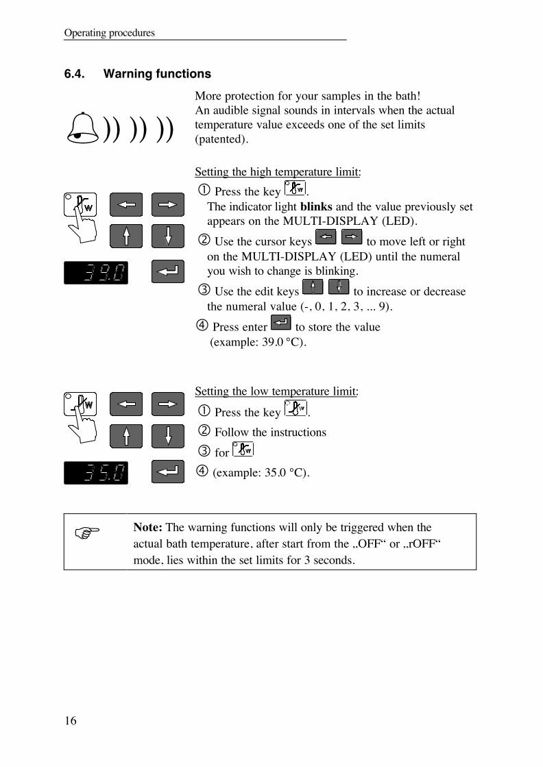
6.4. Warning functions
)) )) ))More protection for your samples in the bath!An audible signal sounds in intervals when the actualtemperature value exceeds one of the set limits(patented).
Setting the high temperature limit: Press the key .
The indicator light blinks and the value previously setappears on the MULTI-DISPLAY (LED).
Use the cursor keys to move left or righton the MULTI-DISPLAY (LED) until the numeralyou wish to change is blinking.
Use the edit keys to increase or decreasethe numeral value (-, 0, 1, 2, 3, ... 9).
Press enter to store the value(example: 39.0 °C).
Setting the low temperature limit:
Press the key . Follow the instructions for (example: 35.0 °C).
Note: The warning functions will only be triggered when theactual bath temperature, after start from the „OFF“ or „rOFF“mode, lies within the set limits for 3 seconds.
MV / MW
17
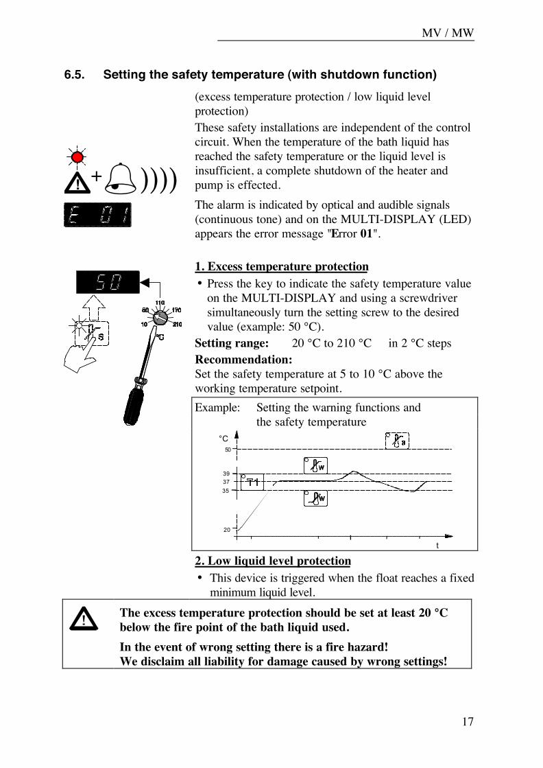
6.5. Setting the safety temperature (with shutdown function)
! +))))
(excess temperature protection / low liquid levelprotection)These safety installations are independent of the controlcircuit. When the temperature of the bath liquid hasreached the safety temperature or the liquid level isinsufficient, a complete shutdown of the heater andpump is effected.The alarm is indicated by optical and audible signals(continuous tone) and on the MULTI-DISPLAY (LED)appears the error message "Error 01".
1. Excess temperature protection• Press the key to indicate the safety temperature value
on the MULTI-DISPLAY and using a screwdriversimultaneously turn the setting screw to the desiredvalue (example: 50 °C).
Setting range: 20 °C to 210 °C in 2 °C stepsRecommendation:Set the safety temperature at 5 to 10 °C above theworking temperature setpoint.Example: Setting the warning functions and
the safety temperature
t
°C
393735
20
50
2. Low liquid level protection• This device is triggered when the float reaches a fixed
minimum liquid level.The excess temperature protection should be set at least 20 °Cbelow the fire point of the bath liquid used.In the event of wrong setting there is a fire hazard!We disclaim all liability for damage caused by wrong settings!
Troubleshooting guide / Error messages
18
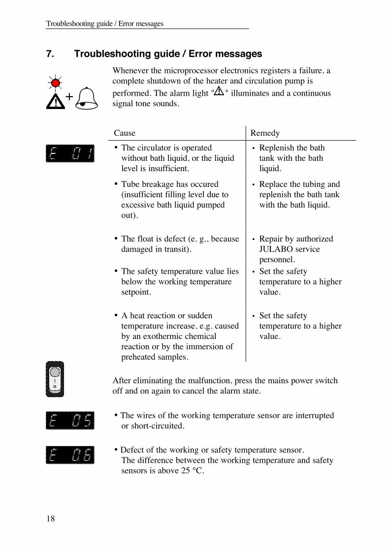
7. Troubleshooting guide / Error messages
! +Whenever the microprocessor electronics registers a failure, acomplete shutdown of the heater and circulation pump isperformed. The alarm light " " illuminates and a continuoussignal tone sounds.
Cause Remedy• The circulator is operated
without bath liquid, or the liquidlevel is insufficient.
• Replenish the bathtank with the bathliquid.
• Tube breakage has occured(insufficient filling level due toexcessive bath liquid pumpedout).
• Replace the tubing andreplenish the bath tankwith the bath liquid.
• The float is defect (e. g., becausedamaged in transit).
• Repair by authorizedJULABO servicepersonnel.
• The safety temperature value liesbelow the working temperaturesetpoint.
• Set the safetytemperature to a highervalue.
• A heat reaction or suddentemperature increase, e.g. causedby an exothermic chemicalreaction or by the immersion ofpreheated samples.
• Set the safetytemperature to a highervalue.
After eliminating the malfunction, press the mains power switchoff and on again to cancel the alarm state.
• The wires of the working temperature sensor are interruptedor short-circuited.
• Defect of the working or safety temperature sensor.The difference between the working temperature and safetysensors is above 25 °C.

MV / MW
19
other errors
After eliminating the malfunction, press the mains power switchoff and on again to cancel the alarm state.If the unit cannot be returned to operation, contact an authorizedJULABO service station.
If the error message "Configuration Error" appears, contact anauthorized JULABO service station.
Disturbances that are not indicated.Pump motor overload protection• The pump motor is protected against overloading.
After a short cooling interval, the motor willautomatically start running.
Mains fuses• The mains fuses on the rear of the unit may easily be
exchanged as shown on the left.
(Fine fuse T 10.0 A, dia. 5 x 20 mm)
Only use fine fuses with a nominal value as specified.
Safety recommendations
20
8. Safety recommendationsFollow the safety recommendations to prevent damage to personsor property. Further, the valid safety instructions for workingplaces must be followed.
Connect the unit only to a grounded mains power socket! Observe the flash point of the bath medium used.
The excess temperature protection should be set at least 20 °Cbelow the fire point.
Pay attention to the thermal expansion of bath oil during heatingto avoid overflowing of the liquid.
Prevent water from penetrating into the hot bath oil. Some parts of the bath cover and the pump connections may
become extremely warm during continuous operation. Therefore,exercise particular caution when touchingthese parts.
Exercise caution when emptying hot bath liquids! Observe the limited working temperature range when using plastic
bath tanks. Employ suitable connecting tubing. Make sure that the tubes are securely attached. Avoid sharp bends in the tubing, and maintain a sufficient distance
from surrounding walls. Regularly check the tubing for material defects (e.g. for cracks). Before cleaning the unit, disconnect the power plug from the
mains socket.
Recommendation:When you have finished the application, it is recommended tokeep on circulating the liquid in the bath or the external system forsome time. Simultaneously set the working temperature to +20 °Cto allow the temperature in the system to decrease slowly.Thus fractional over-heating of the bath liquid is prevented.

MV / MW
21
9. ATC - Absolute Temperature Calibration
Circulator (TT)
Measuring point(TM)
ATC serves to compensate a temperature difference that mightoccur between circulator and a defined measuring point in thebath tank because of physical properties.The difference temperature is determined (ΔT= TM - TT)and stored as correcting factor (example ΔT = -0.2 °C).
Measuring point(TM)
Press the cursor key and enter at the same time. The MULTI-DISPLAY (LED) indicates "Atc0". With the edit keys select "Atc1" and then press
enter . Using the cursor keys and the edit keys
set the correcting factor (example -0.20 °C) and then pressenter .
Press and at the same time.
The temperature on the measuring point rises to a temperatureof 37.0 °C and is indicated on the MULTI-DISPLAY (LED).
Note:The correcting factor always affects the actual workingtemperature, even if this is set via the interface.
The ATC function stays activated until resetting to 00.00 °C.
Recommendation:In case a calibrated temperature measuring instrument is used,the ATC function allows the circulator to be used as testinginstrument according to DIN/ISO 9000.

Configuration for counter-cooling
22
10. Configuration for counter-cooling
Software versionnumber
Model combination
The basic circulator is supplied factory-prefitted withsoftware, e.g. version n 3.0, providing the configurationfor a heating circulator.In case the circulator is to be assembled with a JULABOsolenoid valve controller (MVS see page 9) or aJULABO refrigerated bath, a new configuration must beperformed.
1. Connect the 5-pole control cable between theconnectors " ALARM" and secure attachment.
2. Connect the mains power cables of the circulatorand solenoid valve controller to grounded mainspower sockets. Turn on both mains switches.
3. The unit performs a self-test. Then "CErr" isindicated on the MULTI-DISPLAY and the redindicator light "ALARM" illuminates.
4. Press enter to confirm the message "CErr".
The display indicates "OFF" and the indicator light"ALARM" goes out.
5. Select the initialization level by pressingsimultaneously the keys , and .The value last entered („In 0“) is indicated.
6. By pressing the key set the last digit of theparameter to indicate „In 3“ for use of an MVScontroller.
Model combination Valueusing refrigerated bath type „F“ (e. g. F34) In 2using MVS controller orrefrigerated bath type „FP“ In 3
7. Now press enter to confirm and to finish
initialization.
The new configuration is indicated during the self-test(example n 3.3).

MV / MW
23
11. Electrical connections / ALARM connectorThe " ALARM" connector may be used as output foralarm messages.Circuit: Operation = relay powered
Alarm = relay not poweredPin assignment:Pin 1: +24 V (max. current 25 mA)Pin 2: 0 VPin 3: Alarm relayPin 4: Reserved - do not use!Pin 5: Cooling pulse
RS232C serial interfaceThis port can be used to connect a computer with anRS232C cable for remote control of the circulator.
RS232C
Pin assignments:Pin 2 RxD Receive DataPin 3 TxD Transmit DataPin 5 0 VD Signal GNDPin 6 DTR Data terminal readyPin 7 RTS Request to sendPin 8 CTS Clear to send
Interface correspondence:Circulator Computer Circulator Computer
9-pole 25-pole 9-pole 9-pole Pin 2 RxD ⇔ Pin 2 TxD Pin 2 RxD ⇔ Pin 3 TxDPin 3 TxD ⇔ Pin 3 RxD Pin 3 TxD ⇔ Pin 2 RxDPin 5 GND ⇔ Pin 7 GND Pin 5 GND⇔ Pin 5 GNDPin 6 DTR ⇔ Pin 6 DSR Pin 6 DTR⇔ Pin 6 DSRPin 7 RTS ⇔ Pin 5 CTS Pin 7 RTS ⇔ Pin 8 CTSPin 8 CTS ⇔ Pin 4 RTS Pin 8 CTS ⇔ Pin 7 RTS
Use shielded cables only.
Remote control
24
12. Remote control
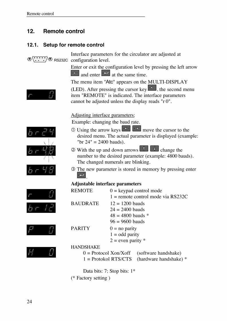
12.1. Setup for remote control
RS232CInterface parameters for the circulator are adjusted atconfiguration level.Enter or exit the configuration level by pressing the left arrow
and enter at the same time.The menu item "Atc" appears on the MULTI-DISPLAY(LED). After pressing the cursor key , the second menuitem "REMOTE" is indicated. The interface parameterscannot be adjusted unless the display reads "r 0".
Adjusting interface parameters:Example: changing the baud rate. Using the arrow keys move the cursor to the
desired menu. The actual parameter is displayed (example:"br 24" = 2400 bauds).
With the up and down arrows change thenumber to the desired parameter (example: 4800 bauds).The changed numerals are blinking.
The new parameter is stored in memory by pressing enter.
Adjustable interface parametersREMOTE 0 = keypad control mode
1 = remote control mode via RS232CBAUDRATE 12 = 1200 bauds
24 = 2400 bauds48 = 4800 bauds *96 = 9600 bauds
PARITY 0 = no parity1 = odd parity2 = even parity *
HANDSHAKE0 = Protocol Xon/Xoff (software handshake)1 = Protokol RTS/CTS (hardware handshake) *
Data bits: 7; Stop bits: 1*(* Factory setting )

MV / MW
25
Like all parameters which can be entered through thekeypad, interface parameters are stored in memoryeven after the circulator is turned off.
12.2. Communication with a PC or a superordinated data system
Suitable terminal programs for communicating with a PC are: MS-Windows - TERMINAL.EXE (included with MS-Windows). MS-DOS - Procomm Plus, Datastrom Technologies. MS-DOS - Norton Utilities.
If the circulator is put into remote control mode via theconfiguration level, the display will read "r OFF" = REMOTESTOP.The circulator is now operated via the computer.In general, the computer (master) sends commands to thecirculator (slave). The circulator sends data (including errormessages) only when the computer asks for it.
A transfer sequence consists of:• command• space (⇔; Hex: 20)• parameter (the character separating decimals in a
group is the period)• end of file (↵; Hex: 0D)
The commands are divided into in or out commands.in commands: asking for parameters to be displayedout commands: setting parameters
The out commands are valid only in remote control mode.
Examples:• Command to set the working temperature T1 to 55.5 °C:
out_sp_00 ⇔ 55.5↵• Command to ask for the working temperature T1:
in_sp_00↵• Response from the circulator:
55.5↵

Remote control
26
12.3. List of commandsCommand Parameter Response of circulator
version none Number of software version (V X.xx)
status none Status message, error message (see below)
out_mode_01 0 Use working temperature "T1" *out_mode_01 1 Use working temperature "T2" *out_mode_05 0 Stop the circulator = r OFF
out_mode_05 1 Start the circulator
out_sp_00 xxx.x Set working temperature "T1"
out_sp_01 xxx.x Set working temperature "T2"
out_sp_02 xxx.x Set high temperature warning limitout_sp_03 xxx.x Set low temperature warning limit .
in_sp_00 none Ask for working temperature "T1"
in_sp_01 none Ask for working temperature "T2"
in_sp_02 none Ask for high temperature warning limit .
in_sp_03 none Ask for low temperature warning limit .
in_pv_00 none Ask for actual bath temperature
in_pv_01 none Ask for the heater wattage being used
12.4. Status messagesMessage Description
00 MANUAL STOP Circulator in "OFF" state
01 MANUAL START Circulator in keypad control mode
02 REMOTE STOP Circulator in "r OFF" state
03 REMOTE START Circulator in remote control mode
(* see "Note" on page 21).

MV / MW
27
12.5. Error messages
Message Description
-01 TEMP / LEVEL ALARM Safety temperature or low liquid levelalarm
-03 EXCESS TEMPERATUREWARNING High temperature warning " "
-04 LOW TEMPERATUREWARNING Low temperature warning " "
-05 TEMPERATUREMEASUREMENT ALARM
Error in measuring system
-06 SENSOR DIFFERENCEALARM
Sensor difference alarm. Workingtemperature and safety sensors reporta temperature difference of more than25 °C.
-07 I2C-BUS WRITE ERROR-07 I2C-BUS READ ERROR-07 I2C-BUS READ/WRITEERROR
Internal error
-08 INVALID COMMAND Invalid command
-10 VALUE TOO SMALL Entered value too small
-11 VALUE TOO LARGE Entered value too large
-12 WARNING : VALUE EXCEEDSTEMPERATURE LIMITS
Value lies outside the adjusted rangefor the high and low temperaturewarning limits. But value is stored.
-13 COMMAND NOT ALLOWEDIN CURRENT OPERATING MODE
Invalid command in current operatingmode

Cleaning the unit
28
13. Cleaning the unit
Before cleaning the unit, disconnect the power plug from themains socket!For cleaning the bath tank and the immersed parts of the circulator,use low surface tension water (e.g., soap suds).Clean the outside of the unit using a wet cloth and low surfacetension water.
Prevent humidity from entering into the circulator.
14. MaintenanceThe circulator is designed for continuous operation under normalconditions. Periodic maintenance is not required.The tank should be filled only with a bath liquid recommended byJULABO. To avoid contamination, it is essential to change thebath liquid from time to time.
RepairsBefore asking for a service technician or returning a JULABOcirculator for repair, please contact an authorized JULABOservice station.
When returning a unit, take care of careful and adequate packing.JULABO is not responsible for damages that might occur frominsufficient packing.
JULABO reserves the right to carry out technical modificationswith repairs for providing improved performance of a unit.
MV / MW
29
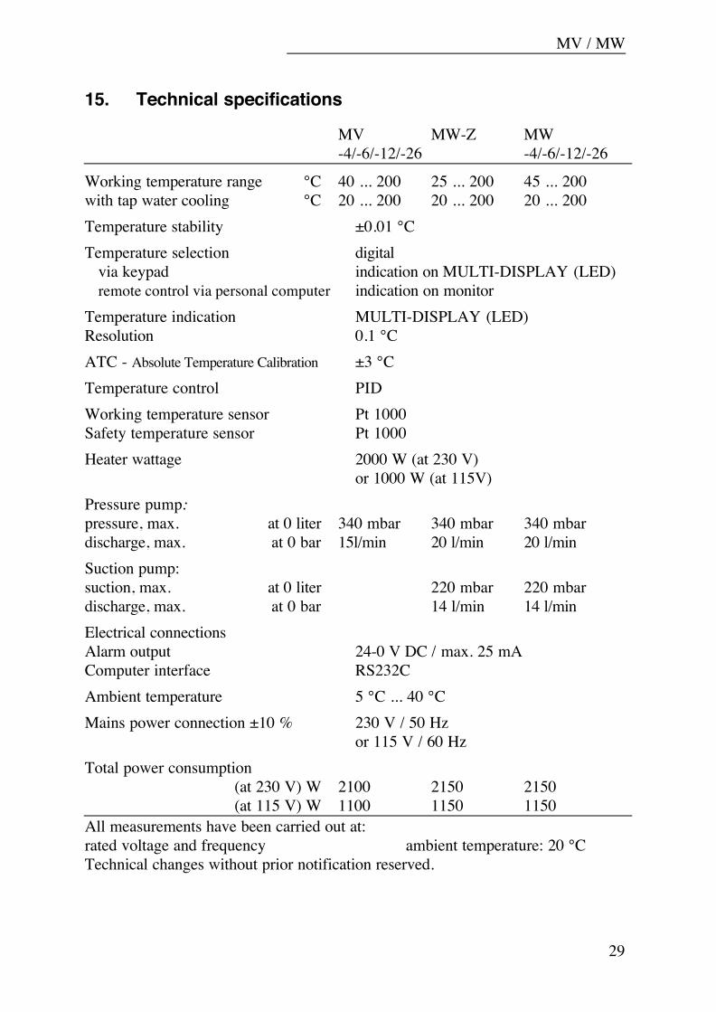
15. Technical specifications
MV MW-Z MW-4/-6/-12/-26 -4/-6/-12/-26
Working temperature range °C 40 ... 200 25 ... 200 45 ... 200with tap water cooling °C 20 ... 200 20 ... 200 20 ... 200Temperature stability ±0.01 °CTemperature selection digital via keypad indication on MULTI-DISPLAY (LED) remote control via personal computer indication on monitorTemperature indication MULTI-DISPLAY (LED)Resolution 0.1 °CATC - Absolute Temperature Calibration ±3 °CTemperature control PIDWorking temperature sensor Pt 1000Safety temperature sensor Pt 1000Heater wattage 2000 W (at 230 V)
or 1000 W (at 115V)Pressure pump:pressure, max. at 0 liter 340 mbar 340 mbar 340 mbardischarge, max. at 0 bar 15l/min 20 l/min 20 l/minSuction pump:suction, max. at 0 liter 220 mbar 220 mbardischarge, max. at 0 bar 14 l/min 14 l/minElectrical connectionsAlarm output 24-0 V DC / max. 25 mAComputer interface RS232CAmbient temperature 5 °C ... 40 °CMains power connection ±10 % 230 V / 50 Hz
or 115 V / 60 HzTotal power consumption
(at 230 V) W 2100 2150 2150(at 115 V) W 1100 1150 1150
All measurements have been carried out at:rated voltage and frequency ambient temperature: 20 °CTechnical changes without prior notification reserved.

Technical specifications
30
Bridge mounted circulator MW-ZUsable immersion depth from 90 to 145 mmOverall dimensions (WxDxH) 320x170x320 mmWeight 5.5 kg
Heating circulators MV/MW-4 MV/MW-6Bath opening mm 130x150 130x150Bath depth mm 150 200Filling volume liters 3 ... 4.5 4.5 ... 6Overall dimensions mm 210x410 210x410
(WxDxH) x370 x430Weight kg 9 / 9 14
Heating circulators MV/MW-12 MV/MW-26Bath opening mm 220x150 220x300Bath depth mm 200 200Filling volume liters 7.5 ... 12 18 ... 26Overall dimensions mm 300x410 360x610
(WxDxH) x450 x450Weight kg 15 20
Safety Installations (DIN 12876)Excess temperature protection adjustable from 20 to 210 °CLow liquid level protection float switchSafety class IIISupplementary safety installations:High temperature warning function optical + audible (in intervals)Low temperature warning function optical + audible (in intervals)Supervision of the working sensor plausibility controlReciprocal sensor monitoring betweenworking and safety sensors difference >25 °CAlarm indication optical + audible
Standards:EMC regulations EN 61326Guideline for first voltage range EN 61010-1, EN 61010-2-010
MV / MW
31
16. EC Declaration of Conformity
The following unit complies with the essential safety requirements outlined by theEC Directives concerning the guidelines for electromagnetic compatibility(89/336/EEC) and for the low voltage regulations (73/23/EEC).
Circulator: MV, MW
This unit is manufactured in compliance with the following guidelines
electrical equipment for control technology and laboratory application –EMC requirements outlined by
EN 61326
safety regulation for electrical devices for measuring, control andlaboratory application specified by
EN 61010
Julabo Labortechnik GmbHEisenbahnstr. 45D-77960 Seelbach / Germany G. Juchheim, Managing
Director

Warranty conditions
32
17. Warranty conditionsJULABO Labortechnik GmbH warrants its products against defects in material orin workmanship, when used under appropriate conditions and in accordance withappropriate operating instructions for a period of no less than
ONE YEAR
Extension of the warranty period – free of charge
With the ‘1PLUS warranty’ the user receives a free of charge extension to thewarranty of up to 24 months or 10.000 working hours; which ever is achievedfirst.
To apply for this extended warranty the user must register the unit on the Julaboweb site www.julabo.de, indicating the serial no. The extended warranty will applyfrom the date of Julabo Labortechnik GmbH’s original invoice.
Julabo Labortechnik GmbH reserves the right to decide the validity of anywarranty claim. In case of faults arising either due to faulty materials orworkmanship, parts will be repaired or replaced free of charge, or a newreplacement unit will be supplied.
Any other compensation claims are excluded from this guarantee.