circuits, symbols, binary, digital logic, design, and...
TRANSCRIPT

Circuits, symbols, Binary, Digital Logic, Design, and Troubleshooting

•Resources
•Introduction to Circuits
•Circuit Design Process
•Electrical Symbols
•Ladder Diagrams
•Latching Circuit Design
•Digital Logic
•Basic Logic Gates
•Sample Circuit Problem
•Digital Logic Circuit Problem Tips
Circuit Design 2

•For more complete documentation, and more detailed information, the following items are available from:
•http://mfranzen.ca/index.html
•Handouts
•http://www.allaboutcircuits.com/
•Volume IV – Digital Section
•LOGO!Soft Comfort Demo Software, Program Help Files & Tutorials
•http://www.automation.siemens.com/mcms/programmable-logic-controller/en/logic-module-logo/demo-software/Pages/Default.aspx
Circuit Design 3

•Circuit design is a process that creates electrical/electronic circuits, simple or complex, to complete tasks safely & efficiently
•An understanding of how electricity /circuit movement , devices, and loads operate is used in several engineering fields
•Communicating those ideas requires a simple communication method using lines and symbols
•Part of this process includes, block troubleshooting, trial and error, step by step methods, and logical analysis
•Circuits should show either:
•Source, control, and loads found in hardware mechanical circuits or
•Input, function, and output – found in digital Logic circuitsCircuit Design 4

•SPICE Process can be applied to Circuit Design
•S ITUATION•Identify the big picture – what is the circuit being used for
•P ROBLEM•What is the challenge – what circuit needs to do
•I DEAS•Investigate and generate ideas – circuit idea possibilities
•C REATE•Construct the best solution – build your best circuit idea
•E VALUATION•Test and troubleshoot – does it work and solve the circuit problem•If not, then go back Ideas step
Circuit Design 5

•Some common symbols:
•Loads
•Sources
•Wiring
•Switches
•Contacts
•Relays
Circuit Design 6

•Used to show circuit schematics - a ladder type simple circuit diagram with •vertical rails representing line power 1 and 2 (feed and return, or +, -)
•Rung(s) representing the circuit components and designed task
•Here is an example of a simple switch and lamp circuit with one rung level in the form of a hardware mechanical/electrical circuit :
Circuit Design 7

•Industry uses latched circuit design to create a safety feature allowing for constant feedback and possible power failure concerns•This type of circuit uses a control relay with momentary push buttons, control contacts and - main power contacts•Key to this circuit below is the M1 relay coil and the M1 latch contact•When the coil is energized by momentary forward push button, it changes the state of all contacts attached including the M1 control contact (below), and the M1 Power contact (above)
Circuit Design 8
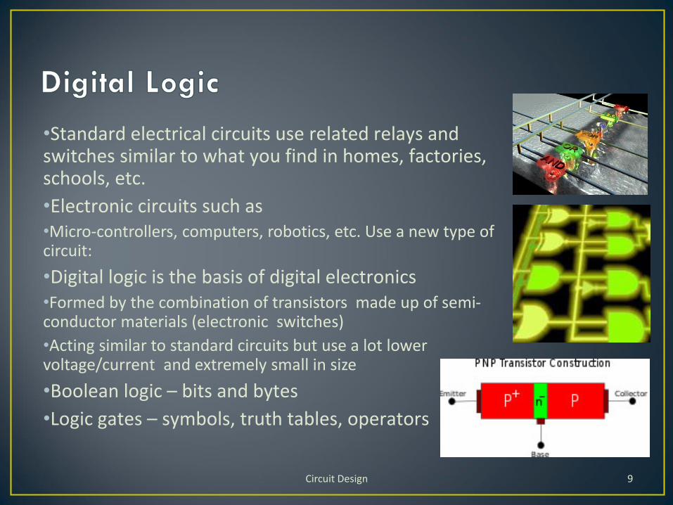
•Standard electrical circuits use related relays and switches similar to what you find in homes, factories, schools, etc.
•Electronic circuits such as•Micro-controllers, computers, robotics, etc. Use a new type of circuit:
•Digital logic is the basis of digital electronics •Formed by the combination of transistors made up of semi-conductor materials (electronic switches)
•Acting similar to standard circuits but use a lot lower voltage/current and extremely small in size
•Boolean logic – bits and bytes
•Logic gates – symbols, truth tables, operators
Circuit Design 9
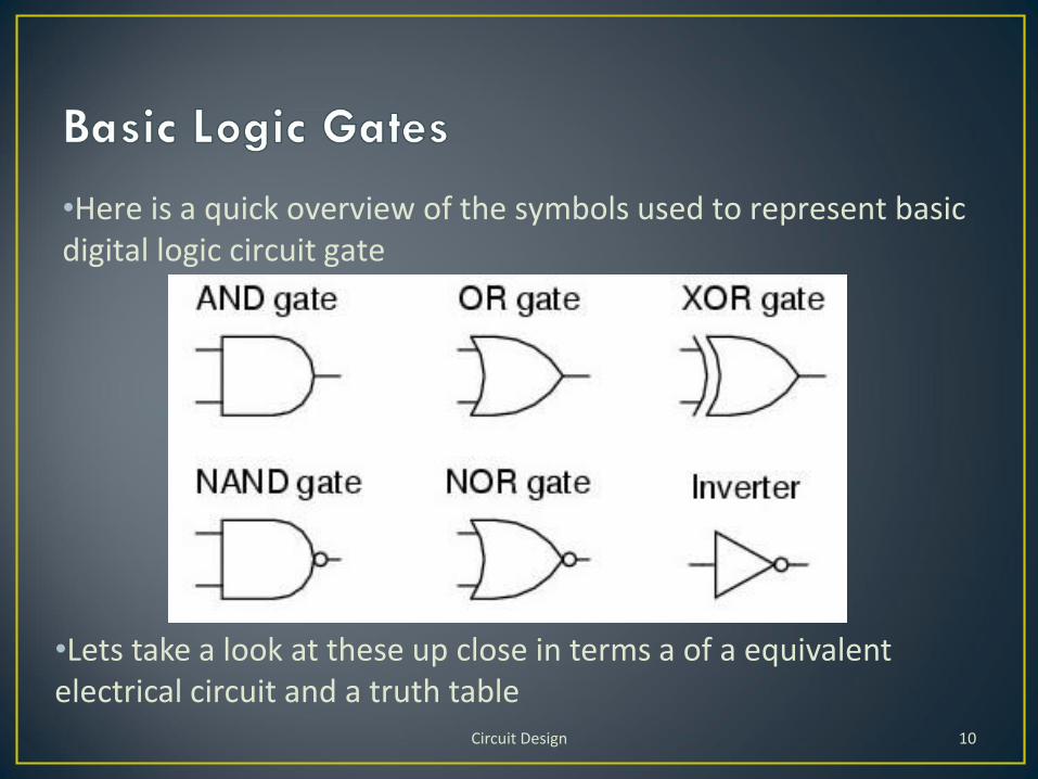
•Here is a quick overview of the symbols used to represent basic digital logic circuit gate
Circuit Design 10
•Lets take a look at these up close in terms a of a equivalent electrical circuit and a truth table

•A and B must both be high/on in order for output to be high/on
Circuit Design 11

•Either A or B can be high/on to produce a high/on output
Circuit Design 12

•The small circle on the end of the triangle represents the inverter, so if A is a high/on, then the output will be Low/off
Circuit Design 13

•Opposite of an AND gate because of the inverter.
•Both A and B must be High/on to get a output of Low/off
Circuit Design 14

•Opposite of an OR gate because of the inverter.
•Both A and B must be Low/off to get a output of High/on
Circuit Design 15

•Exclusive OR will only have a High/on output if either A or B only have a High/on
Circuit Design 16

•Given: Create an equivalent logic circuit that forces a operator to push two buttons at the same time in order to energize control relay 1 that will activate the load/machine to start. If one or both buttons are released the load/machine will stop.
•Step 1: Draw the standard hardware/electrical circuit required
Circuit Design 17

Step 2: If this is the first time to using this software, familiarize yourself with this programs interface, toolbars, and logic gates neededStart up LOGOSoft Comfort and insert title, name, given information, and Sub titles for Inputs, Functions, and outputs using the text tool Circuit Design 18

Step 3: Neatly insert a title, description of circuit operation, and sub titles; Inputs, Functions, and Outputs spread out on page at topStep 4: Insert your known inputs and outputs in appropriate locations, then figure out what is needed for you functions –drag and dropStep 5: Label and set configurations for all inputs, functions, and outputs using comment command in the actual object’s menuStep 6: Connect all your wiring, organize placement of objects using alignment tools and make sure wiring is not crossing and is easy to follow
Circuit Design 19

Step 7: Simulate circuit using F3 to test if circuit is working properly
Circuit Design 20

•Know your basic logic gates
•Use SPICE to guide you through circuit design process
•Break down circuit requirements into blocks/sections and work on one section at a time
•Think series or parallel circuit operation to ensure proper connections and operation
•Use LOGO!Soft Comfort Demo Software :•http://www.automation.siemens.com/mcms/programmable-logic-controller/en/logic-module-logo/demo-software/Pages/Default.aspx
•…to create, test, modify, and troubleshoot your circuit design idea
•Ensure components are neat, organized, and labelled
•Show your Inputs, Functions, and Outputs titles and ensure your circuit is in this order across the horizontal of the page
•Fit your diagram on a single page
•Do not cross wires unless absolutely unavoidable
Circuit Design 21