circuit stepper motor driver
TRANSCRIPT
7/27/2019 Circuit Stepper Motor Driver
http://slidepdf.com/reader/full/circuit-stepper-motor-driver 1/17
The 2008 Unipolar Stepper Motor Driver circuit has been replaced by a newer version.
2012 - Stepper Motor Driver Circuit
UNIPOLAR Stepper Motor Driver (2008)
This page features simple and inexpensive, stand alone UNIPOLAR stepper motor driver using parts that
are available from many sources.
The driver is designed for medium and low speed app lications with motors that draw up to 1.0 amperes per
phase.
This driver provides only basic control functions such as: Forward, Reverse, Stop and has a calculated Step
rate adjustment range of 0.72 (1.39 sec) to 145 steps per second. (Slower and faster step rates are also
possible. - See notes.)
The only step angle for this driver is the design step angle of the motor itself. 'Half-stepping' is not
possible.
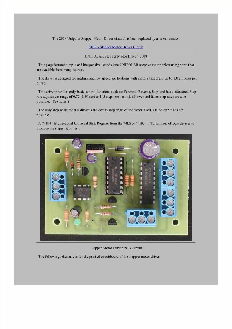
A 74194 - Bidirectional Universal Shift Register from the 74LS or 74HC - TTL families of logic devices to
produce the stepp ing pattern.
Stepper Motor Driver PCB Circuit
The following schematic is for the printed circuitboard of the stepper motor driver.

7/27/2019 Circuit Stepper Motor Driver
http://slidepdf.com/reader/full/circuit-stepper-motor-driver 2/17
Basic Controls For The Stepper Driver
The direction is selected by an ON-OFF-ON toggle switch.
The stepping rate is shown being set by a 1 Megohm potentiometer (RT). Using the component values
shown for R1, RT, R2 and C1, the calculated step rate range is between 0.72 steps per second (1.39 seconds)
to 145 steps p er second.
Basic Stepper Motor Driver Operation
The LM555 (IC 1) astable oscillator produces CLOCK pulses that are fed to PIN 11 of the 74194
(IC 2) shift register.
1.
Each time the output of the LM555 timer goes HIGH (positive) the HIGH state at the 74194's
OUTPUT terminals, (PIN's 12, 13, 14, 15), is shifted either UP or DOWN by one place.
The direction of the output shifting is controlled by switch S1. When S1 is in the OFF position
(centre) the HIGH output state will remain at its last position and the motor will be stopped.
2.

7/27/2019 Circuit Stepper Motor Driver
http://slidepdf.com/reader/full/circuit-stepper-motor-driver 3/17
Switch S1 controls the direction indirectly through transistors Q2 and Q3.
When the base of Q2 is LOW the output shifting of IC 2 will be pins 15 - 14 - 13 - 12 - 15; .etc.
When the base of Q3 is LOW the output shifting of IC 2 will be pins 12 - 13 - 14 - 15 - 12; .etc.
The direction of the output's shifting determines the direction of the motor's rotation.
The outputs of the 74194 are fed to four sets of paralleled segments of a ULN2803 Darlington driver
(IC 3).
When an input of a ULN2803 segment is HIGH, its darlington transistor will turn ON and that
OUTPUT will conduct current through one of the motors coils.
3.
As the coils of the motor are turned ON in sequence the motor's armature rotates to follow these
changes. Refer to following diagram.
4.
Inputs Vs. Outputs Waveforms
The following diagram shows the stepping order for the outputs of the ULN2803 (IC 3) as compared to theinput and output of the 74194 (IC 2). The output is shown stepping in one direction only.

7/27/2019 Circuit Stepper Motor Driver
http://slidepdf.com/reader/full/circuit-stepper-motor-driver 4/17
Integrated Circuit Chips Used
IC 1 - LM555 - Timer, normally configured as an astable oscillator but can be used a monostable
timer for 1 step at a time operation or can be used as a buffer between external inputs and IC2. (See
later Diagrams.)
IC 2 - 74194 - 4-Bit Bidirectional Universal Shift Register. The shift register provides the logic that
controls the direction of the drivers output steps.
This circuit can use either t he 74LS194 or t he 74HC194 shift register IC. Their logic functions are
identical but the 74HC194 IC is a CMOS type that can be damaged by static electricity discharges.
Antist atic precautions should be used when handling the 74HC194 to avoid damage.
If you are purchasing your own p arts use the 74LS194 IC if it is available.
IC 3 - ULN2803 - 8 Segment, Darlington, High Current , High Voltage Peripheral Driver. Each
segment can handle currents of up to 500 milliamps and voltages up to 50 volts. In this circuit 2
output segments are connected in parallel, this allows a maximum output current of 1 amp per phase.
IC 4 - LM7805 - Positive 5 Volt Regulator. Provides low voltage power to the driving circuitry and
can also power external control circuits.
It is not the purpose of this page to provide full explanations of how these devices work. Detailed
explanations can be found through datatsheets that are available from many source on the internet.
74194 Stepp er Motor Driver Notes
Due to the lack of error detection and limited step power, this circuit should not be used for
applications that require accurate positioning. (The driver is designed for hobby and learning
uses.)
7/27/2019 Circuit Stepper Motor Driver
http://slidepdf.com/reader/full/circuit-stepper-motor-driver 5/17
There are links to other stepper motor related web pages further down the page. These may be
helpful in understanding stepper motor operation and control.
For the parts values shown on the schematic, if the external potentiometer (RT) is set to "ZERO"
ohms, the calculated CLOCK frequency will be approximately 145 Hz and a motor will make 145
steps per second. This step rate should be slow enough for most motors to operate properly.
The maximum RPM at which stepper motors will operate properly is low when compared to other
motor types and the torque the motor produces drops rapidly as its speed increases. Testing may be
needed to determine the minimum values for RT and C1 to produce the maximum CLOCK frequencyfor any given motor. Data sheets, if available, will also help determine this frequency.
If RT is set to 1 Megohm, the calculated step rate will be 0.73 Hz and the motor would make 1 step
every 1.39 seconds.
There is no minimum step speed at which stepper motors cannot operate. Therefore, in theory, the
values for RT and C1 can be as large as desired but there are practical limitations to these values. The
main limitation is the 'leakage' current of electrolytic capacitors.
External CLOCK pulses can also be used to control the driver by passing them through IC 1 via the
"T2" terminal of the circuitboard. Using IC 1 as an input buffer should eliminate "noise" that could
cause the 74194's output to go into a state where more than one output is HIGH.
If stepp ing rates greater than 145 per second are needed, capacitor C1 can be replaced with one of
lower value.
A 0.47uF capacitor would give a calculated range of 1.5 to 310 st eps per second.
A 0.33uF capacitor would give a calculated range of 2.2 to 441 st eps per second.
Alternately, capacitor C1 can be removed from the circuitboard and an external clock source
connected at terminal 'T2'. With C1 removed, the practical limit on the step rate is the motor itself.
In the above items the "calculated" minimum and maximum CLOCK frequencies are valid for the
nominal part values shown. Given the tolerances of actual components and the leakage currents of
electrolyt ic capacitors the actual CLOCK rates may be lower or higher.
The direction of the motor can be controlled by another circuit or the parallel output port of a PC.
This will work as long as the voltage at the bases of Q2 and Q3 can be made lower than 0.7 volts.
Additional NPN transistors may be required to achieve this result, depending on the method used.
If the bases of both Q2 and Q3 are made LOW at the same time the SN74194 will go into a RESET
mode. This will cause the step sequence to stop and on the next clock pulse pins 15 and 14 will go to a
HIGH state.
Making the bases of both Q2 and Q3 LOW at the same time can be used to reset the SN74194 to its
starting position without having to remove the circuit power.
Each stepper motor will have its own power requirements and as there is a great variety of motors
available. This page cannot give information in this area. Users of this circuit will have to determine
motor phasing and power requirements for themselves.
Power for the motors can be regulated or filtered and may range from 12 to 24 volts with currents up
to 1,000 milliamps depending on the particular motor.
Motors that operate at voltages lower than 12 volts can also be used with this driver but a separate
supply of of 9 to 12 volts will be needed for the control portion of the circuit in addition to the low
voltage supply for the motor.
7/27/2019 Circuit Stepper Motor Driver
http://slidepdf.com/reader/full/circuit-stepper-motor-driver 6/17
A LED connected to the output of the LM555 timer (IC 1) flashes at the CLOCK frequency. If a
direction has been selected, The motor will move one step every t ime the led turns ON.
There is no CLOCK output terminal on the circuitboard but there is a pad to the right of the LED
that can be used if a clock output signal is required. This pad is connected to pin 3 of the LM555 IC.
The LM7805, positive 5 volt regulator used on the circuitboard can also be used to provide power
for external control circuits. With its tab trimmed off, the regulator can easily dissipate up to 1 watt .
For a 12 volt supply, external circuits can draw up to 100 milliamps.
For a 24 volt supply, external circuits can draw up to 25 milliamps.
The photo of the circuitboard shows the tab of the 7805 regulator cut off, this is an option that is
available on request.
74194 Stepper Driver Initialization Notes
When power is applied to the 74194 Stepper Driver circuit there is a very short delay before
stepping of the outputs can begin. The delay is controlled by Capacitor C2, resistor R4 and transistor
Q1.
The function of the delay is to allow the outputs of IC 2 to be set with pin 12 in a HIGH state and
pins 13, 14 and 15 in a LOW state before direction control becomes active. The delay also prevents IC
1 from oscillating until IC 2 has been set.
If the power to the circuit is turned off, there should be a pause of at least 10 seconds before it is
reapplied. The p ause is to allow capacitor C2 to discharge through R4 and D2.
If the initialization delay were not used, IC 3 could have: none, any or all of its outputs in a high state
when stepping is started. This would cause the motor to move incorrectly or not at all during normal
operation.
The stepper motor driver is ready to start operation as soon as the the initialization delay is complete.
* - The DigiKey part number for IC 2 is for the 74HC194 - CMOS IC. This IC is a CMOS type that can
be damaged by static electricity discharge.
DigiKey does not carry the 74LS194 in small quantities. It is available for other sources such as Mouser
Electronics - stock number 47053 and Jameco Electronics - stock number 59574LS194AN as well as many
other sources. Be sure that the IC's have the DIP package.
* - The Part Number for Q1, Q2 and Q3 is for 2N3904s. Almost any NPN, Switching or Small signal type
will work, the 2N4400 is one example.
Please Read
Due to delays in acquiring 74LS194 type ICs, the assembled circuitboards and kits will use the74HC194 - CMOS type IC. The 74HC194 will be mounted in a socket to el iminate soldering this
device during assembly.
Although the 74HC194 is sensitive to damage from static discharge, once i t is install ed in i ts socket
the IC is very safe as all of its pins are connected to the 5 volt supply or to common through low
impedance paths.
A good practice is to touch the work surface before touching the circuitboard.
PCB Parts Placement Diagram

7/27/2019 Circuit Stepper Motor Driver
http://slidepdf.com/reader/full/circuit-stepper-motor-driver 7/17
Other Information And Diagrams
Wiring for longer distances.
If the motor is some distance from the circuit board or power supply, it might be best to separate the
motor's power supply lead from the circuit board's supply as illustrated in the next diagram. The motor
could be connected using larger gauge wire.
This will keep most effects of the motors current pulses away from the supply to the circuit board. A filter
capacitor could be placed in the motor's supply circuit as well.

7/27/2019 Circuit Stepper Motor Driver
http://slidepdf.com/reader/full/circuit-stepper-motor-driver 8/17
Connecting A 6 Lead Motor to the Stepper Driver
It may be necessary to move the coil leads around to get the motor to turn properly. Leave one wire
connected permanently and change the other three coil leads as needed.
Single-Step Input
The connections in the following diagram will allow the motor to make single steps. A toggle switch could
be used to select between single and continuous steps if the 1 Megohm potentiometer was included in the
circuit.

7/27/2019 Circuit Stepper Motor Driver
http://slidepdf.com/reader/full/circuit-stepper-motor-driver 9/17
Stepper Driver Controlled By Computer Parallel Ports
In most cases the 74194 stepper driver circuits can be directly controlled from the parallel ports of
computers that have 0 and 5 volt outp ut st ates.
This also applies to other logic devices with 0 and 5 volt output states. Consult the particular device's
datasheet for their specifications.
External Controls Using Transistors
External Controls Using Optoisolators

7/27/2019 Circuit Stepper Motor Driver
http://slidepdf.com/reader/full/circuit-stepper-motor-driver 10/17
The use of optoisolators p rovides complete isolation between the driver and the external control circuit.
Automated M otor Cont rol Circuit - (Voltage Comparators)
The circuit above replaces the direction control switch with a "window" ty pe voltage comparator circuit.
Potentiometer "R IN" could be a temperature or light sensing circuit.

7/27/2019 Circuit Stepper Motor Driver
http://slidepdf.com/reader/full/circuit-stepper-motor-driver 11/17
When the voltage at the centre tap of R IN is between the HIGH and LOW voltages set by resistors
R1, R2, and R3 the motor will be stopped.
When the voltage at the centre tap of R IN is above the HIGH voltage between R1 and R2 the motor
will be step in the FWD direction.
When the voltage at the centre tap of R IN is below the LOW voltage between R2 and R3 the motor
will be step in the REV direction.
In a p ractical app lication the direction of the motors load, a heating duct damper for example, would bringthe temperature represented by the voltage at R IN back to the range between the HIGH and LOW voltage
setpoints.
The limit switches at the outputs of the comparators are used to prevent the damper from going beyond its
minimum and maximum positions by to stop ping the motor.
Also see Voltage Comparator Information And Circuits - Voltage Window Detector Circuit.
Slower Step Rates
Additional capacitance can be added to the IC 1 circuit t o provide slower motor step rates. There is a limit
to this approach as control of the step rate becomes less accurate as the capacitance increases and at some
point the timer will stop working due to the leakage currents of the capacitors.
Fast External Clock
An external clock with a step rate greater than 145 steps p er second can be connected to the driver circuit by removing capacitor C1. There is no limit on how slow the clock input can be.

7/27/2019 Circuit Stepper Motor Driver
http://slidepdf.com/reader/full/circuit-stepper-motor-driver 12/17
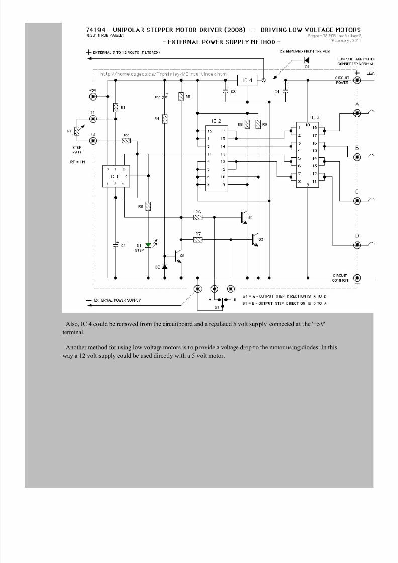
Using Low Voltage Motors
Stepper motors that require less than 12 volts can be controlled by the driver by removing diode D3 from
the circuitboard and connecting a external power supply to t he control section of the driver.
7/27/2019 Circuit Stepper Motor Driver
http://slidepdf.com/reader/full/circuit-stepper-motor-driver 13/17
Also, IC 4 could be removed from the circuitboard and a regulated 5 volt sup ply connected at the '+5V'
terminal.
Another method for using low voltage motors is to provide a voltage drop to the motor using diodes. In this
way a 12 volt supply could be used directly with a 5 volt motor.

7/27/2019 Circuit Stepper Motor Driver
http://slidepdf.com/reader/full/circuit-stepper-motor-driver 14/17
Single Input Direction Control
The following circuits allow the direction of the motor to be controlled by as single, ON-OFF input. The
maximum input voltage is 5 Volts.

7/27/2019 Circuit Stepper Motor Driver
http://slidepdf.com/reader/full/circuit-stepper-motor-driver 15/17
Using Higher Current Motors
The next circuit uses TIP125 Darlington type transistors to increase the current capacity of the 74194
driver circuit to 5 amps per winding.
Depending on the current required for the motor, small heatsinks may be needed for the t ransistors.

7/27/2019 Circuit Stepper Motor Driver
http://slidepdf.com/reader/full/circuit-stepper-motor-driver 16/17
Other Information
Animated operation of stepper motors.
http://de.nanotec.com/schrittmotor_animation.html
For the motor driver circuit on this web page, only 1 coil is ON at a time so the rotor of the motor would be
aligned with one of the stator's poles and not half way between poles as shown in the animation.
The following links are for stepper motor related pages that have information on other types of driver
circuits and motors.
www.cs.uiowa.edu/~jones/step/circuits.html
www.doc.ic.ac.uk/~ih/doc/stepp er/control2/connect.html
Return to the Main Page
Please Read Before Using These Circuit Ideas
The e xplanations for the circuits on these pages cannot hope to cover every situation on every
layout. For this reason be prepared to do some experimenting to get the results you want. This is
especially true of circuits such as the "Across Track Infrared Detection" circuits and any other
circuit that reli es on other than direct electronic inputs, such as switches.

7/27/2019 Circuit Stepper Motor Driver
http://slidepdf.com/reader/full/circuit-stepper-motor-driver 17/17
If you use any of these circuit ideas, ask your parts supplier for a copy of the manufacturers data
sheets for any components that you have not used before. These sheets contain a wealth of data and
circuit design information that no electronic or print article could approach and will save time and
perhaps damage to the components themsel ves. These data shee ts can often be found on the web site
of the device manufacturers.
Although the circuits are functional the pages are not meant to be ful l descriptions of each circuit
but rather as guides for adapting them for use by others. If you have any questions or comments
please send them to the email address on the Circuit Index page.
Return to the Main Page
09 February, 2013