circuit examples - lc automation safety... · the following circuit examples have been checked with...
TRANSCRIPT

kapitel 7
Circuit Examples

7.1 Safety-Related Low-Voltage Switchgear and Sensors
7.2 Controllers: Fail-safe controls
7.3 Motion Control Systems: Safe Motion Control

The following circuit examples havebeen checked with the German TradeAssociation (BG) and have beenapproved.
EMERGENCY STOP circuits forextremely simple machines
EMERGENCY STOP switch
The EMERGENCY STOP function may only be routed through an EMER-GENCY STOP switch for extremelysimple machines, depending on theresult of the risk analysis. In this partic-ular case, only Stop Category 0 is pos-sible. Such an EMERGENCY STOPswitch, contrary to usual EMERGENCYSTOP pushbutton, interrupts the maincircuit (Fig. 7/1).
7/2 Safety Integrated Application Manual Siemens AG
An EMERGENCY STOP switch mustbe configured so that
• There is only one EMERGENCYSTOP switch;
• The EMERGENCY STOP switch islocated in the supply to those circuitswhich can result in hazardous motionin the system. The complete powersupply to all of the circuits does nothave to be interrupted;
• The EMERGENCY STOP switch mustbe able to interrupt the current ofthe largest motor when the motorstalls;
• The sum of the currents of all of theloads, which must be disconnectedusing the EMERGENCY STOPswitch, must be able to be safelyinterrupted.
An EMERGENCY STOP switch may
• be manually actuated;
• act on an undervoltage release viaone or several EMERGENCY STOPcontrol devices (circuit diagram 7/1);
• be provided with overload and/orshort-circuit releases (version ascircuit-breaker);
• be simultaneously used as mainswitch if it additionally fulfills therequirements for a main switch(however, a main switch mustdisconnect all circuits).
An example for such an EMERGENCYSTOP switch for extremely simplemachines is illustrated in Fig. 7/2
7.1 Safety-Related Low-Voltage Switchgear and Sensors
To loads which do not have to beor may not be disconnected forEMERGENCY STOP
Line supply disconnection(main switch)
Supply
EMERGENCY STOP switch
Manual drivemechanism
U<
Switch lockReleaseMushroomheadpushbutton
EMERGENCYSTOPcontrol device(alternative actuation)
Fig. 7/1EMERGENCY STOP switch with manual actuation or remote actuation via under-voltagerelease
• Contactor circuits
• SIGUARD safety combinations
suitable for:
• EMERGENCY STOP
• Protective door monitoring func-tions
• Press controls
7.1.1 Switch safely

EMERGENCY STOP contactor
Generally, a so-called EMERGENCYSTOP contactor is not permitted. Sucha contactor is only permissible in pre-cisely defined exceptional cases: Thiscontactor may only be used as anEMERGENCY STOP contactor in thebranch to be shutdown. Additionalcontactors in series are not permitted.This means that this concept is restric-ted for applications on extremely sim-ple machines (refer to circuit diagram7/2).
An EMERGENCY STOP contactormust be configured so that
• each EMERGENCY STOP contactormust be immediately de-energizedby the EMERGENCY STOP controldevice;
• there are no additional contactors in series.
Safety circuits using individualcontactors
Configured using two auxiliarycontactors
Safety circuits of any complexity canbe configured using auxiliary contac-tors. Several years ago, the circuit withtwo auxiliary contactors and overlap-ping auxiliary contacts (Fig. 7/3) wasconsidered to be state-of-the-art.
This circuit offers redundancy. However,due to the fact that the contacts arenot positively driven, the two auxiliarycontactors do not mutually monitoreach other for correct functioning. Thismeans that if a contact welds, thisfault is not detected and the circuitstill continues to function.
A subsequent fault in the secondcontactor could completely disable thecombination. This would mean that thelevel of safety would no longer be gua-ranteed. Thus, today, this circuit is nolonger used (Fig. 7/3).
Safety Integrated Application Manual Siemens AG 7/3
777
EMERGENCYSTOP controldevice in thecontrol circuit
To loads which do nothave to be or may notbe disconnected forEMERGENCY STOP
Mainswitch
Supply To loads which must be shutdownfor EMERGENCY STOP
Fig. 7/2Example of a machine control with 2 power contactors,only permitted with some restrictions
L1
Actuator “On“or “On“ afterEMERGENCYSTOP
N
K1
K2
K2K1
EMERGENCY STOP device,if required several in series K1
K2
Enable signals
K1
K2
- No positively driven contacts- No self-monitoring
F1
Today, this circuit is no longer used
Fig. 7/3This contactor combination consists of two auxiliary contactors withoverlapping contacts (Category 2 according to EN 954-1)

Configured using three auxiliarycontactors
Today, circuits with three auxiliarycontactors represent state-of-the-arttechnology. Three auxiliary contactorswith positively driven contacts areused, as shown in circuit diagram 7/4.The three auxiliary contacts guaranteeredundancy and function monitoring.The positively driven contacts guaran-tee that the auxiliary contactorsmutually monitor themselves. Faultsare therefore detected and the circuitcan no longer be closed after shutdo-wn, therefore eliminating subsequentfaults.
With this circuit, using today's state-of-the-art technology, it can be assumedthat if the auxiliary contactors incor-rectly function, this will not cause thesystem to go into a hazardous condi-tion.
Connecting several EMERGENCYSTOP control devices
In the previous circuit diagrams, onlyone EMERGENCY STOP device wasshown. Generally, there are severalEMERGENCY STOP control devices(e.g. at different locations) on a machi-ne.The contacts of these EMERGENCYSTOP control devices are then connec-ted in series.
7/4 Safety Integrated Application Manual Siemens AG
Circuit examples to monitor protec-tive devices
Circuits to monitor protective devicesuse position switches. Various possibi-lities of the different devices are sho-wn in the examples for EMERGENCYSTOP. These circuit examples will notbe repeated here as the EMERGENCYSTOP control device is only replacedby one or two position switches per
protective device. The number of posi-tion switches which are required foreach protective door can be takenfrom Section 3 of the Manual.
L+/L1
K3
K1
Actuator “On“or control voltage"On"
L–/NK2 K3
EMERGENCY STOP device,if required several in series
K1 K2
K1
K1
K3
K2
K3
K1
K2
Enable signals
K3
F1
Fig. 7/4Contactor combination using three auxiliary contactors with self-monitoring,single-channel, Category 3(4) acc. to EN 954-1
Doors
Open
Closed
Closed
Open
Fig. 7/6SIGUARD position switches used to monitor movingprotective equipment
In the 3TK28 contactor safety combi-nations, which are complete devices,several auxiliary contactors are con-nected to form a safety circuit. These
circuits can also be implementedusing individual contactors.
1-channel
EMERGENCYSTOPcontrol devices
2-channel
EMERGENCYSTOPcontrol devices
Fig. 7/5Several EMERGENCY STOP control devices

Safety Integrated Application Manual Siemens AG 7/5
7777.1.2 SIGUARD 3TK28 Safety Combinations
12
3
1
2
3
4
4
ϑ
K1
K2
K1 K2
K1
K1C1
V1
K2
K1
K2
A1
A2
Y34 Y22 Y21 13 23
Y11 Y12 14 24
Y33
K2
Power supply
“Ready ON”feedback circuit
Sensor(e.g. EMERGENCY STOP pushbutton)
Sensor(e.g. EMERGENCY STOP pushbutton2-channel)
Enable circuit
Enable circuit
“POWER” LED
“Channel 1” LED
“Channel 2” LED
PTC fuse
A1/A2
Y33/34
Y11/12
Y21/22
13/14
23/24
12
3
4
Power on;Connect the power;The “Power” LED is lit, EMERGENCY STOP closed,C1 is charged, press ON,C1 starts to charge K1, V1 is energized,K2 starts, K1 + K2 latch,“Channel 1” and “Channel 2” LED‘s are lit.
ON monitoringON is pressed fault!EMERGENCY STOP is closed,V1 immediately starts K2, C1 is not charged K1 does not start.Only LED “Channel 2” is lit.
Cross-circuitIf EMERGENCY STOP 1 and EMERGENCY STOP 2 areshort-circuited, a current flows through the PTC fuse.The PTC goes into a high-ohmic state.None of the LED‘s are lit.
Function description
ϑA1
A2
Y11 Y12 14 24
H2H1K1
K2
K1
K1
K1C1
V1
K2
H3K1
K2
Y33 Y34 Y22 Y21 13 23
K2
K2
Fig. 7/7Internal circuit diagram of the 3TK28 23
Fig. 7/8Function description of the 3TK28 23
1
2 3 1
2
3
4
4
A1/A2
Y1/Y2
13/14
23/24
33/34
41/42
Power supply viaEMERGENCY STOP pushbutton
“ON”Feedback circuit
Enable circuit
Enable circuit
Enable circuit
Signaling circuit
LED “POWER“
LED “Channel 1“
LED “Channel 2“
PTC fuse
K2
13Y2 Y1 23 (33) (41)
K1
K1
14
K2
K1
(42)(34)24
K2
K2K1
A1
A2
ϑ
Fig. 7/9Internal circuit diagram of the 3TK28 21/24

7/6 Safety Integrated Application Manual Siemens AG
M
M
M
13 23
14 24K2
A2K1
N/–N/–
EMERGENCYSTOP
A1
24 V AC/DCL/+
(34) (42)
(33) (41)
K3K3 H1
K2
K1
K1
K2
K3
ON
Y1 Y2
3TK
28 2
1/24
Fig. 7/103TK28 21/24 for EMERGENCY STOP,Category 2, single channel,with feedback circuit
EMERGENCY SWITCHING-OFF(EMERGENCY STOP) circuits
Circuit diagrams
The following circuit diagrams havebeen checked with the German TradeAssociation (BG) and approved.Connection designation:The connection designations are incompliance with DIN EN 50042.
M
13 23
14 24
K2
K1
K2
A2
K1
N/–N/–
EMERGENCYSTOP
A1
24 V AC/DC L/+
(34) (42)
(33) (41)
ON
Y1
K1
K2
3TK
28 2
1/24
Y2
H1Fig. 7/113TK28 21/24 EMERGENCY STOP,Category 3 (4),two-channel with feedback circuit
M
K2
K1
Y11 Y34 13 23
14 24
K2
A2Y21 Y22
K1
N/–N/–
EMER-GENCYSTOP
A1 Y12
ON
L/+
Y33
K1
K2
3TK
28 2
3
24 V AC/DC
Fig. 7/123TK28 23 for EMERGENCY STOP,Category 4, two-channel,with feedback circuit, monitored start

Safety Integrated Application Manual Siemens AG 7/7
777
Fig. 7/13 3TK28 25 EMERGENCY STOP, Category 2, single-channel, according to EN 954-1, monitored start
Fig. 7/14 3TK28 25 EMERGENCY STOP, Category 4, two-channel, according to EN 954-1, monitored start
M
K3
M
K1
M
K2
13 23
14 24
K2
Y33
K1
N/–
A1
L/+
34 42
33 41Y22
Y44
L/+
N/–
52
51
PE
K3
PE
K1
K2
ON
Y21
Y34
Y12
Y43
Y10 Y11
K3
3TK
28 2
5
A2
EMER-GENCYSTOP
H2H1
M
13 23
14 24
K2
Y33
K1
N/–
A1
L/+
34 42
33 41Y22
Y44
L/+
N/–
52
51
PE
PE
K1
K2
ON
Y21
Y34
Y12
Y43
Y10 Y11
3TK
28 2
5
A2
K1
K2
EMER-GENCYSTOP
H2H1
Y33
A1 Y22
L/+
N/–
PE
PE
K1
ON
Y21
Y34
Y12Y10 Y11
3TK
28 2
7
A2
13 23
14 24
N/–
L/+
32 48
31 47
58
57
K2K1
K2 K1
EMER-GENCYSTOP
H1
M MK2
Fig. 7/15 3TK28 27 EMERGENCY STOP, Category 2, single-channel, according to EN 954-1, monitored start
7/8 Safety Integrated Application Manual Siemens AG
Y33
A1 Y22
L/+
N/–
PE
PE
K1
K2
ON
Y21
Y34
Y12Y10 Y11
3TK
28 2
7
A2
13 23
14 24
N/–
L/+
32 48
31 47
58
57
K2K1
EMER-GENCYSTOP
H1
K2
K1
M
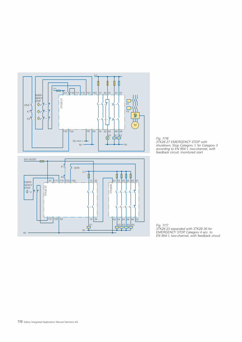
Fig. 7/163TK28 27 EMERGENCY STOP withshutdown, Stop Category 1, for Category 3according to EN 954-1, two-channel, with feedback circuit, monitored start
K5
K1
Y34 13 23
14 24
K1
N/–N/–
ON
L/+
Y33 A1
K2 K3 K4 K5
13 23 33 43 51
A2 14 24 34 44 52
3TK
2830
Y11
A2Y21 Y22
EMER-GENCYSTOP
A1 Y12
24 V AC/DC
3TK
28 2
3
Fig. 7/173TK28 23 expanded with 3TK28 30 forEMERGENCY STOP, Category 4 acc. to EN 954-1, two-channel, with feedback circuit

Safety Integrated Application Manual Siemens AG 7/9
777
Fig. 7/183TK28 25 expanded by 3TK28 30 for EMERGENCY STOP, Category 4 acc. to EN 954-1, two-channel cc. to EN 954-1, monitored start
Fig. 7/193TK28 27 expanded by 3TK28 30 for EMERGENCY STOP, Category 4 (Category 3 for delayed contacts), two-channel, monitored start
24 V AC/DC
Y33
A1 Y22
N/–
PE
PE
K1
K5
ON
Y21
Y34
Y12Y10 Y11
3TK
28 2
5
A2
13 23
14 24
K2K1
N/–
L/+
34 42
33 41
52
51 A1 13
14
K3
N/–
A2
N/–
23
K4
33
K5
43
K6
51
24 34 44 52
3TK
2830
K6
H2H1
EMER-GENCYSTOP
Y33
A1 Y22
24 V AC/DC
N/–
PE
PE
K1
ON
Y21
Y34
Y12Y10 Y11
3TK
28 2
7
A2
13 23
14 24
K2K1
N/–
L/+
32 48
31 47
58
57 A1 13
14
N/–
A2
N/–
23
K4
33
K5
43
K6
51
24 34 44 52
3TK
2830
K7
K3 K7
EMER-GENCYSTOP
H1

7/10 Safety Integrated Application Manual Siemens AG
Fig. 7/20EMERGENCY STOP, Category 4 acc. to EN954-1, 3TK2823(25) in conjunction with operational control of a standard PLC (SIMATIC S7-300/ET200M), load current for each enable circuit, max. 5 A. When using 3TK285.-.. max. 10 A for each enable circuit
M 3TK
28 4
1
K2
1L+
Y12Y11 13 23A1
A2 14 24
Y32
K4 K6 • • • K16
M
2019
17
13
15
11
2MK15
K9
2L+
M7
4
3
S7 300
0
M
109
7
3
5
1
1M
K1
K7
Backplane businterface
Channel numberStatus display, green
M
L+24V DC
• •
• •
••
• •
• •
• •
• •
••
• •
• •
For 3TK2825, additionalsignaling output for PLCor via auxiliary contact
K15
K16
Y32
K1
K16
• •
3TK
28 4
1
Y12Y11 13 23A1
Y22Y21 A2 14
Y32
M
L+24V DC
EMERGENCY STOP
Y32
K1
K16
• •
• •
• •
• •
•
K1
K2
ON
Fig. 7/21EMERGENCY OFF, Category 2 acc. to EN954-1, 3TK2821 in conjunction with operational control of a standard PLC(SIMATIC S7-300/ET200M), load current, max. 5 A per output group (8 digital outputs)
M
3TK
28 2
1/24
1L+
Y2Y1 13 23A1
A2 14 24
M
2019
17
13
15
11
2MK8
K5
2L+
M7
4
3
S7 300
0
M
1M
K1
K4
Backplanebus interface
Channel numberStatus display, green
M
L+24V DC
EMERGENCYSTOP
• •
• •
••
• •
• •
• •
• •
••
• •
• •
109
7
3
5
1K1
K2
K8
• •
ON4133
34 42
• •
• •
• •
•
K1
K2
K8
Signaling contactfor PLC
Safety Integrated Application Manual Siemens AG 7/11
777
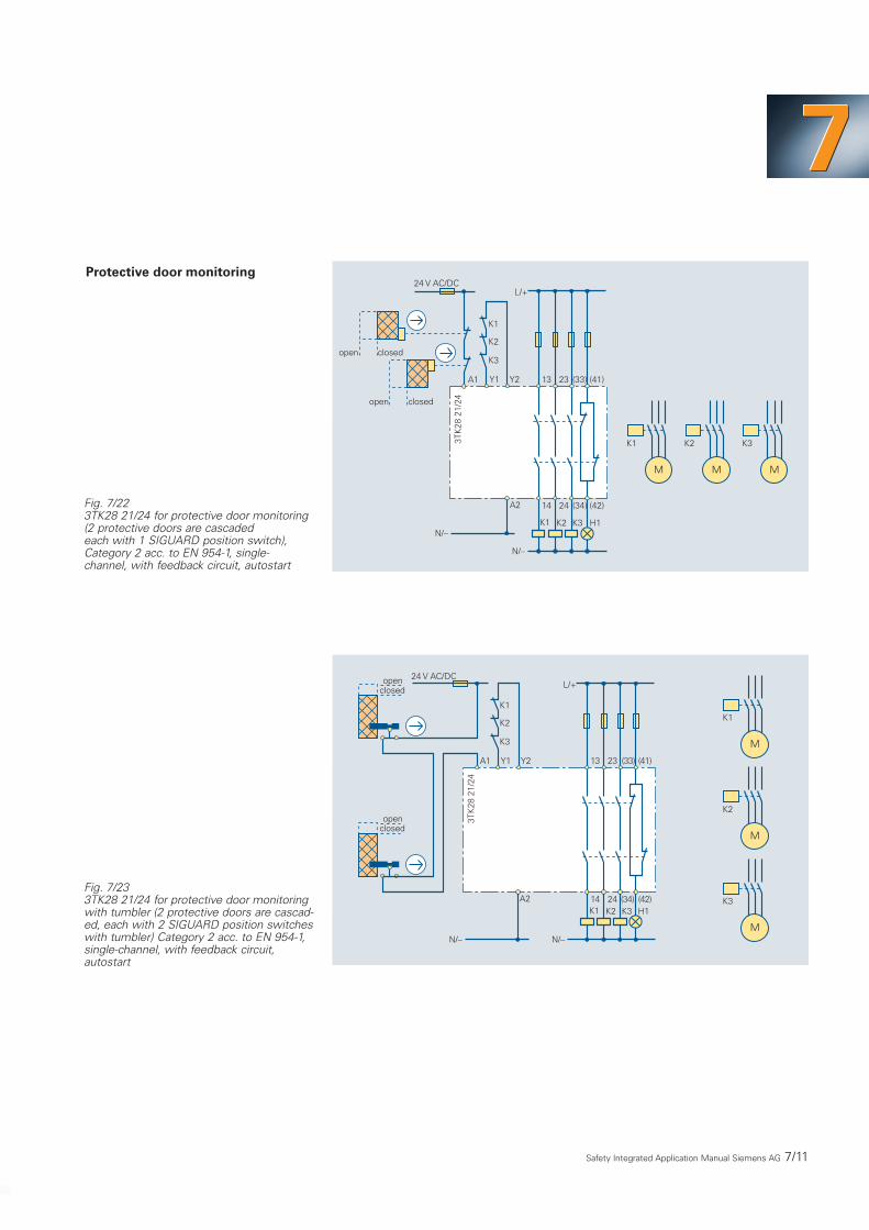
Fig. 7/223TK28 21/24 for protective door monitoring(2 protective doors are cascaded each with 1 SIGUARD position switch),Category 2 acc. to EN 954-1, single- channel, with feedback circuit, autostart
MM M
13 23
14 24
K2
A2
K1
N/–
N/–
A1
24 V AC/DCL/+
(34) (42)
(33) (41)
K3
K2K1 K3
open closed
3TK
28 2
1/24
K1
K2
K3
Y1 Y2
H1
open closed
Protective door monitoring
Fig. 7/233TK28 21/24 for protective door monitoringwith tumbler (2 protective doors are cascad-ed, each with 2 SIGUARD position switcheswith tumbler) Category 2 acc. to EN 954-1,single-channel, with feedback circuit,autostart
13 23
14 24K2
A2K1
N/–N/–
A1
24 V AC/DCL/+
(34) (42)
(33) (41)
K3K3 H1
K2
K1K1
K2
K3
Y1 Y2
openclosed
openclosed
3TK
28 2
1/24
M
M
M

7/12 Safety Integrated Application Manual Siemens AG
Fig. 7/253TK28 22 for protective door monitoring(protective doors, each with 2 SIGUARDposition switches).Category 4 acc. to EN 954-1,two-channel, with feedback circuit, autostart
M
13 23
14 24K2
A2K1
N/–
N/–
A1
24 V AC/DC
L/+
(34) (42)
(33) (41)
K1
K2
open closed
3TK
28 2
1/24
K1
K2
Y1 Y2
H1∞
∞
∞
∞
open closed
M
13 23
14 24K2
A2K1
N/–N/–
A1
24 V AC/DCL/+
Y33 Y34
open closedK1
K2
Y21
Y11
Y22
Y12
3TK
28 2
2
K1
K2
Fig. 7/243TK28 21/24 for protective door monitoring(2 protective doors are cascaded, each with2 SIGUARD position switches), Category 3(4) acc. to EN 954-1, two-channel, with feed-back circuit, autostart, ( ∞ for Category 4 -the cable has to be routed so that it is wellprotected). Sensors must be fail-safe.

Safety Integrated Application Manual Siemens AG 7/13
777
Fig. 7/273TK28 25 for protective door monitoring with 2 SIGUARD position switches, autostart,Category 4 acc. to EN 954-1, two-channel, with feedback circuit
Fig. 7/263TK28 25 for protective door monitoring (2 protective doors are cascaded, each with 1 SIGUARD positionswitch), autostart, Category 2 acc. to EN 954-1, single-channel, with feedback circuit
MMM
13 23
14 24
K2
A2
K1
N/–
A1
L/+
34 42
33 41Y22L/+
N/–
52
51Y21
Y34
Y12
Y44
Y10 Y11
Y43
PE
PE
K3
K2K1 K3
K1
K2
closedopen
open closed
K3
3TK
28 2
5
Y33
H2H1
M
13 23
14 24
K2K1
N/–
L/+
34 42
33 41
52
51
open closed
3TK
28 2
5
K2
K1
A2
A1 Y22L/+
N/–
Y21
Y34
Y12
Y44
Y10 Y11
Y43
PE
PE
K1
K2
Y33
H1 H2

7/14 Safety Integrated Application Manual Siemens AG
Fig. 7/283TK28 28 for protective door monitoring (2 protective doors are cascaded, each with 1 SIGUARD positionswitch), Stop Category 1, Category 2 acc. to EN 954-1, single-channel, with feedback circuit, autostart
Fig. 7/293TK28 28 for protective door monitoring with 2 SIGUARD position switches, stop Category 1,Category 3 acc. to EN 954-1, two-channel, with feedback circuit, autostart
M M
A2
A1L/+
PE
Y21
Y33
Y12Y10 Y11
N/–
PE
13 23
14 24
N/–
L/+
32 48
31 47
58
57
K2K1
K1 K2
K1
closedopen
open closed
K2
3TK
28 2
8Y22
Y34
H1
M
13 23
14 24
N/–
L/+
32 48
31 47
58
K2K1
K23TK
28 2
8 K1
A2
A1
L/+
PE
Y21
Y33
Y12Y10 Y11
N/–
PE
K1 open closed
K2
Y22
Y34
H1
57

Safety Integrated Application Manual Siemens AG 7/15
777
N/–
A1
K3 K4 K5 K6
13 23 33 43 51
A2 14 24 34 44 52A2
A1
24 V AC/DC
N/
Y21
Y34
Y12Y11Y10
PE
PE
13 23
14 24
K2K1
N/–
L/+
34 42
33 41Y22
Y44 52
51
N/–
K1
K6open closed
3TK
28 2
5
3TK
28 3
0
Y33 Y43
H2H1
Fig. 7/303TK28 25 expanded by 3TK28 30 for protective door monitoring with 2 SIGUARD position switches,Category 4 acc. to EN 954-1, two-channel, with feedback circuit, autostart
Fig. 7/31Protective door monitoring with magnetically-operated switch,Category 3 acc. to EN 954-1, two-channel, with feedback circuit, autostart
Magnetically-operated switch
MagnetsReedcontacts
L/+
1 1
2 2
N/- N/-
K1
K2
Y33 Y34Y12Y11A1
A2Y22Y21
13 23
14 24
K1 K2
L1 L2 L324V AC/DC
K1
K2

Protective door monitoring withcontactless SIGUARD magnetically-operated switches
Protective doors are monitored usingan evaluation unit up to Cat. 3 acc. toEN 954-1 (Fig. 7/32).
The evaluation unit can be operated,both with automatic restart as well aswith monitored start.The start buttonis not necessarily required.
Monitoring several protective doorswith evaluation unit up to Cat. 3acc. to EN 954-1
A maximum of eight SIGUARD mag-netically-operated switches can beconnected to the 3SE6808-6DB evalu-ation unit. If one of the eight magneti-cally-operated switches is actuated(the protective door is opened), thenthe unit shuts down.There is a PLC signaling output (switch-ing to p) for each input.The fail-safeshutdown is realized using two relaysafety outputs.
If an input is not used, then the appro-priate terminals of the NO contactmust be bridged.
For limited safety requirements, theevaluation unit can also be used with-out a start button. For this particularapplication, contacts X1 and Y1 mustbe permanently bridged.
7/16 Safety Integrated Application Manual Siemens AG
Fig. 7/32SIGUARD magnetically-operated switch with 3SE6801-1CC evaluation unitfor Category 3 acc. to EN 954-1
M3~
/L/+
0V
+24 V DC
S21
K1
K2
S22 14 24S14S13
A1 A2 Y1 X1 13 23
sw/b
k 13
bl/b
l 14
100 mA
br/b
r 21
ws/
wh
22
K3
K4
//N/-Enable
START
I max.
µP1
µP2
3SE
680
1-1C
C

Safety Integrated Application Manual Siemens AG 7/17
777
Fig. 7/33A maximum of 8 protective doors can be monitored using SIGUARD magnetically-operated switches and evaluation unit 3SE6808-6DB for Category 3 acc. to EN 954-1
Magnetically operatedswitch 5
+PLC
+24 V
4AT
Magnetically operatedswitch 6
Magnetically operatedswitch 7
Magnetically operatedswitch 8
Signaling outputsto the PLC
Y5 Y6 Y7 Y8 Y+ L+ 23
S21 S22S13 S14 Y1 Y2 Y3 Y4 X4 L– 24
13
14Signaling outputsto the PLC
Magnetically operatedswitch 1
Magnetically operatedswitch 2
Magnetically operatedswitch 3
Magnetically operatedswitch 4
0 V
START
(C)1998
S21 S22S13 S14
S21 S22S13 S14
S21 S22S13 S14
S21 S22S13 S14
S21 S22S13 S14
S21 S22S13 S14
S21 S22S13 S14
3SE
6808
-6D
B

For press control devices with contac-tors also refer to Pages 7/14 and 7/15.
7/18 Safety Integrated Application Manual Siemens AG
Press control devices
Fig. 7/34Internal circuit diagram of the 3TK28 34 two-hand control device
Fig. 7/353TK28 34 two-hand control device, Category 4 acc. to EN 954-1
13 23
14 24 32 42
4131
A2 Y33
A1 Y23
3TK
28 3
4
6
4
5
Y32
Y22
Y31
Y21Y12Y11
1 23
ϑ
OperatingvoltageOutputs
A1A213, 1423, 2431, 3241, 42Y11, Y12Y21, Y22, Y23Y31, Y32, Y33
Inputs
L/+N/–Enable circuit 1 (NO contact)Enable circuit 2 (NO contact)NC contactNC contactFeedback circuitPushbutton S1Pushbutton S2
Power supply unit
PTC fuse
Control logic
Channel 1
Channel 2
Safety circuit
1
2
3
4
5
6
13 23
14 24 32 42
4131
A2 Y33
A1 Y23
3TK
28 3
4
Y32
Y22
Y31
Y21Y12Y11S1, S2 button on the two-hand operating consoleH1 signaling lampsK1, K2 must be contactors with positively drivencontacts
K1 H1
S1K1
K2
L/+ L/+
S2
K2
N/–N/–
K1
K2
M
Safety Integrated Application Manual Siemens AG 7/19
777
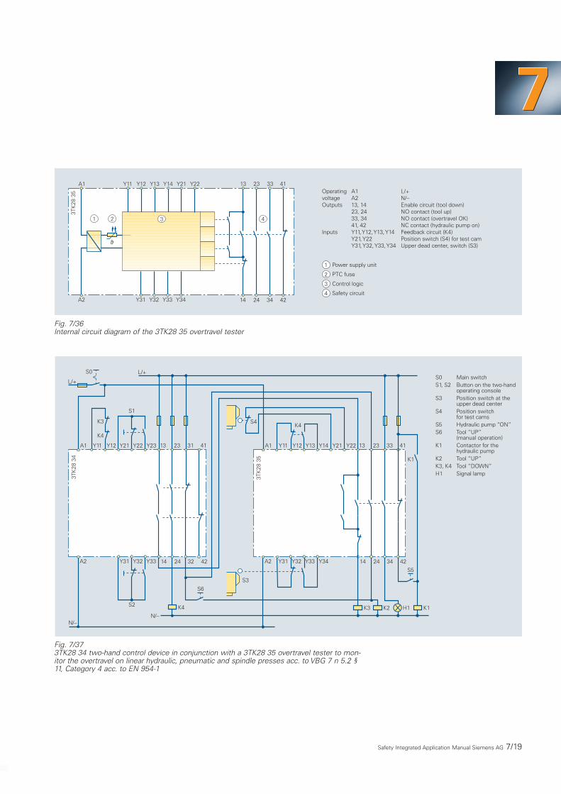
Fig. 7/36Internal circuit diagram of the 3TK28 35 overtravel tester
Fig. 7/373TK28 34 two-hand control device in conjunction with a 3TK28 35 overtravel tester to mon-itor the overtravel on linear hydraulic, pneumatic and spindle presses acc. to VBG 7 n 5.2 §11, Category 4 acc. to EN 954-1
1 2 3 4
1
2
3
4
13 23
14 24 34 42
4133
A2 Y33
A1 Y21
3TK
28 3
5
Y32
Y14
Y31
Y13Y12Y11
Y34
Y22
Power supply unit
PTC fuse
Control logic
Safety circuit
OperatingvoltageOutputs
A1A213, 1423, 2433, 3441, 42Y11, Y12, Y13, Y14Y21, Y22Y31, Y32, Y33, Y34
Inputs
L/+N/–Enable circuit (tool down)NO contact (tool up)NO contact (overtravel OK)NC contact (hydraulic pump on)Feedback circuit (K4)Position switch (S4) for test camUpper dead center, switch (S3)
ϑ
Main switchButton on the two-handoperating consolePosition switch at theupper dead centerPosition switchfor test camsHydraulic pump “ON”Tool “UP”(manual operation)Contactor for thehydraulic pumpTool “UP”Tool “DOWN”Signal lamp
S0S1, S2
S3
S4
S5S6
K1
K2K3, K4H1
K4
N/–
13 23
14 24 34 42
4133
A2 Y33
A1 Y21
3TK
28 3
5
Y32
Y14
Y31
Y13Y12Y11
K2
K4
Y22
S4
Y34
K3
K1
K1H1
S5
S6
S3
13 23
14 24 32 42
4131
A2 Y33
A1 Y23
3TK
28 3
4
Y32
Y22
Y31
Y21Y12Y11
S1
K3
K4
L/+
L/+
S2
N/–
S0
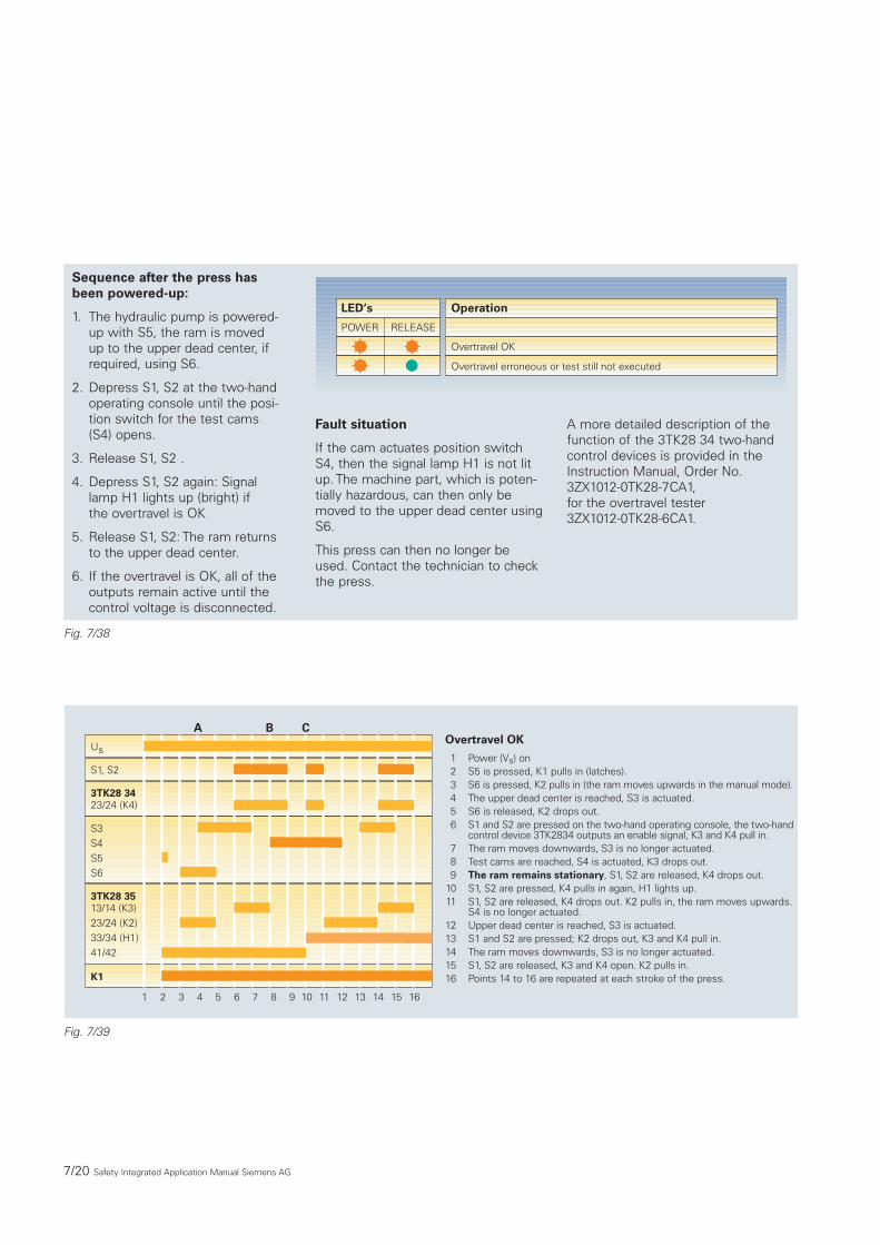
Fig. 7/38
Sequence after the press hasbeen powered-up:
1. The hydraulic pump is powered-up with S5, the ram is moved up to the upper dead center, ifrequired, using S6.
2. Depress S1, S2 at the two-handoperating console until the posi-tion switch for the test cams(S4) opens.
3. Release S1, S2 .
4. Depress S1, S2 again: Signallamp H1 lights up (bright) if the overtravel is OK
5. Release S1, S2: The ram returnsto the upper dead center.
6. If the overtravel is OK, all of theoutputs remain active until thecontrol voltage is disconnected.
7/20 Safety Integrated Application Manual Siemens AG
Fig. 7/39
Fault situation
If the cam actuates position switchS4, then the signal lamp H1 is not litup. The machine part, which is poten-tially hazardous, can then only bemoved to the upper dead center usingS6.
This press can then no longer beused. Contact the technician to checkthe press.
A more detailed description of thefunction of the 3TK28 34 two-handcontrol devices is provided in theInstruction Manual, Order No.3ZX1012-0TK28-7CA1,for the overtravel tester3ZX1012-0TK28-6CA1.
LED‘s Operation
POWER RELEASE
Overtravel OK
Overtravel erroneous or test still not executed
123456
789
1011
1213141516
Power (Vs) onS5 is pressed, K1 pulls in (latches).S6 is pressed, K2 pulls in (the ram moves upwards in the manual mode).The upper dead center is reached, S3 is actuated.S6 is released, K2 drops out.S1 and S2 are pressed on the two-hand operating console, the two-handcontrol device 3TK2834 outputs an enable signal, K3 and K4 pull in.The ram moves downwards, S3 is no longer actuated.Test cams are reached, S4 is actuated, K3 drops out.The ram remains stationary, S1, S2 are released, K4 drops out.S1, S2 are pressed, K4 pulls in again, H1 lights up.S1, S2 are released, K4 drops out. K2 pulls in, the ram moves upwards.S4 is no longer actuated.Upper dead center is reached, S3 is actuated.S1 and S2 are pressed; K2 drops out, K3 and K4 pull in.The ram moves downwards, S3 is no longer actuated.S1, S2 are released, K3 and K4 open. K2 pulls in.Points 14 to 16 are repeated at each stroke of the press.
Overtravel OKUs
3TK28 3423/24 (K4)
S3S4S5S6
3TK28 3513/14 (K3)23/24 (K2)33/34 (H1)41/42
K1
S1, S2
1 2 3 4 5 6 7 8 9 11 12 13 14 15 1610
A B C

Safety Integrated Application Manual Siemens AG 7/21
777
Fig. 7/40
Fig. 7/41Function schematic of the press control.The permissible overtravel “s” corresponds to the length of the cam which actuates position switch S4.According to ZH 1/456, the press manufacturer must define “s”.
123
456
789
1011
Power (Vs) onS5 is pressed, K1 pulls in (latches).S6 is pressed, K2 pulls in (the ram moves upwards in the manualmode).The upper dead center is reached, S3 is actuated.S6 is released, K2 drops out.S1 and S2 on the two-hand operating console are pressed, the 3TK2834two-hand control device outputs enable signals, K3 and K4 pull in.The ram moves downwards, S3 is no longer actuated.Test cams are reached, S4 is depressed, K3 drops out.The ram does not remain stationary, S4 is no longer actuated(is passed over), K3 pulls in.S1 and S2 are released, K3 and K4 drop out.S1, S2 are actuated, K4 pulls in again. Overtravel tester is inhibited.
Overtravel too longUS
3TK28 3423/24 (K4)
S3S4S5S6
3TK28 3513/14 (K3)23/24 (K2)33/34 (H1)41/42
K1
S1, S2
1 2 3 4 5 6 7 8 9 11 12 13 14 15 1610
A B D
A
S3
S4
SS
B C D !

Fig. 7/42SIGUARD 3TK28 41, internal circuit diagram, standard electronic device
Fig. 7/43SIGUARD 3TK28 40, basic electronic device, EMERGENCY STOP, 2-channel,Category 3 acc. to EN 954-1
MicrocontrollerMOS FETDriverEnable circuits(electronic, safe)(dyn. monitored)Sensor connection(dyn. monitored)Feedback circuitON button(monitored)
1234
5
6
Y11 Y12 Y35 Y21 Y22 Y32 Y34 1 A1
A2 14 24
1
5 6
4
3
2µC1 µC2
Y12Y11 Y33 Y34A1
A2Y22 14 24Y21 Y20
K1 K2
EMERGENCYSTOP
M
* *
3TK
28 4
0
K1 K2
ONL+
MM
K1
K2
7/22 Safety Integrated Application Manual Siemens AG
Circuit examples SIGUARDelectronic safety combinations
777
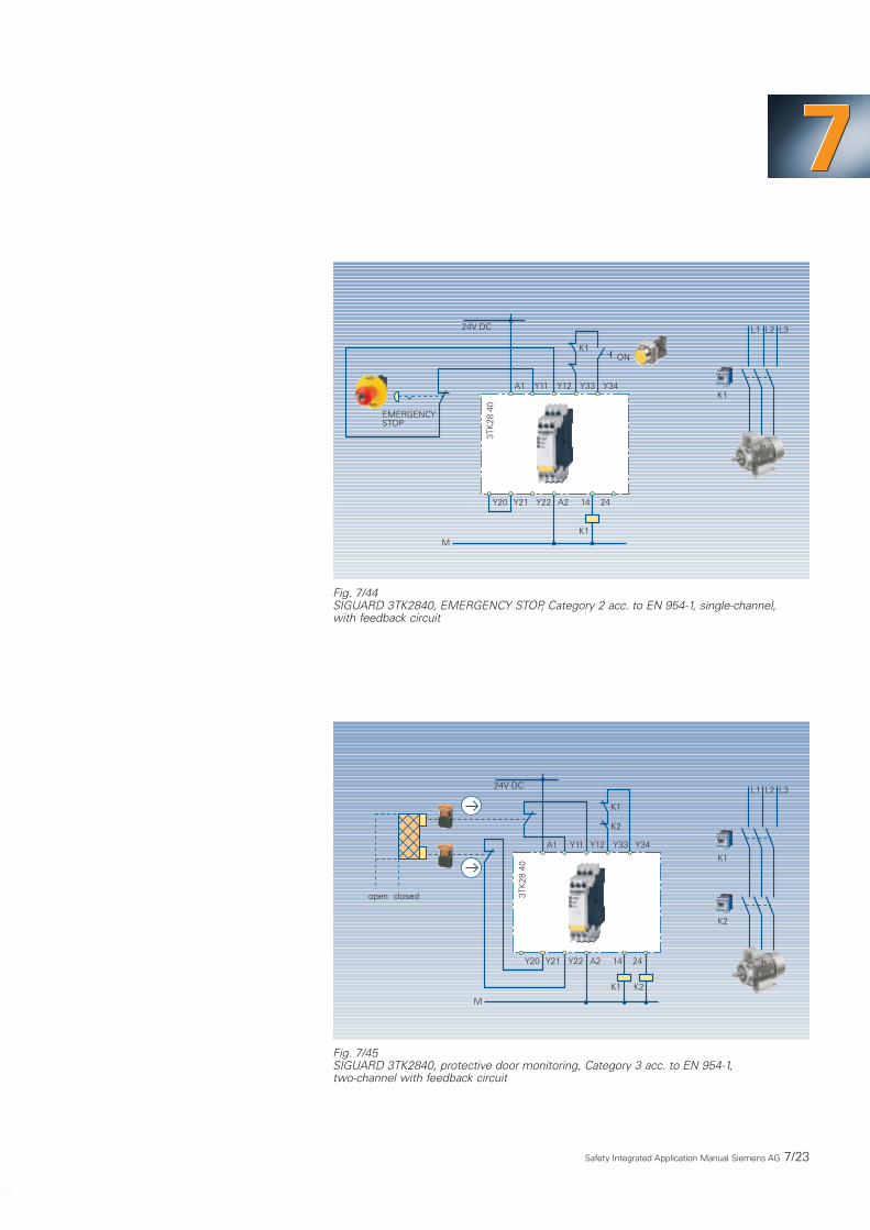
Fig. 7/44SIGUARD 3TK2840, EMERGENCY STOP, Category 2 acc. to EN 954-1, single-channel,with feedback circuit
Fig. 7/45SIGUARD 3TK2840, protective door monitoring, Category 3 acc. to EN 954-1,two-channel with feedback circuit
Y12Y11 Y33 Y34A1
K1
24V DC
M
Y22Y21 A2 14Y20 24
K1
3TK
28 4
0
L1 L2 L3
EMERGENCYSTOP
K1
ON
L1 L2 L3
Y12Y11 Y33 Y34A1
K1
24V DC
M
Y22Y21 A2 14Y20 24
K1
3TK
28 4
0
K2
K2
open closed
K1
K2
Safety Integrated Application Manual Siemens AG 7/23

Fig. 7/47SIGUARD 3TK2841, EMERGENCY STOP,Category 2 acc. to EN 954-1, one-channel, with feedback circuit, monitored start
Y12Y11 Y33 Y34A1
K1
M
Y22Y21 A2 14Y35 24
K1
3TK
28 4
1
K2
K2
L+ L1L2L3
L1L2L3
EMERGENCY STOP
K1
K2
ON
Fig. 7/46SIGUARD 3TK2841, protective door monitoring,Category 4 acc. to EN 954-1, two-channel with feedback circuit, autostart
L1 L2 L3
Y12Y11 Y33 Y34A1
K1
24V DC
M
Y22Y21 A2 14Y35 24
K1
3TK
28 4
1
K2
K2
1
open closed
K1
K2
7/24 Safety Integrated Application Manual Siemens AG

777
Safety Integrated Application Manual Siemens AG 7/25
Fig. 7/48SIGUARD 3TK2841, EMERGENCY STOP, Category 4 acc. to EN 954-1,two-channel, with feedback circuit, monitored start with “ON” button
Fig. 7/49SIGUARD 3TK2841, light grid monitoring, Category 4 acc. to EN 954-1,2-channel, with feedback circuit, autostart
Y12Y11 1 Y34A1
K1
M
Y22Y21 A2 14Y35 24
K1
3TK
28 4
1
K2
K2
L1 L2 L3
24V DC
K1
K2
ON
EMERGENCY STOP
L1 L2 L3
Y12Y11 1 Y34A1
K1
M
Y22Y21 A2 14Y35 24
K1
3TK
28 4
1
K2
K2
L+
Y32
QSSD 1 2
K1
K2

7/26 Siemens AG Safety Integrated Application Manual
Fig. 7/50SIGUARD 3TK2841, EMERGENCY STOP, 2-channel, monitored start,with additional on button and protective door monitoring, 2-channel,autostart, Category 4 acc. to EN 954-1
Fig. 7/51SIGUARD 3TK2841, contact mat, Category 3 acc. to EN 954-1, 2-channel, autostart
L1 L2 L3
K1
K2
Y12Y11 1 Y34A1
M
K1
3TK
28 4
1
K2
L+
Y32
Y22Y21 14 24Y35 A2
Y12Y11 1 Y34A1 Y32
3TK
28 4
1
Y22Y21 14 24Y35 A2
K1 K2
ON
EMERGENCYSTOP
Protective door
L1 L2 L3
K1
K2
Y12Y11 1 Y34A1
K1
M
Y22Y21 A2 14Y35 24
K1
3TK
28 4
1
K2
K2
L+
Y32Contact mat

Siemens AG Safety Integrated Application Manual 7/27
777
Fig. 7/52SIGUARD 3TK2841, EMERGENCY STOP, Category 4 acc. to EN 954-1,in conjunction with operational control of a standard PLC (SIMATIC S7 300/ET200M) load current for each enable circuit, max. 2 A
Fig. 7/53SIGUARD 3TK2841, EMERGENCY STOP and light grid, Category 4 acc. to EN 954-1,cascaded with operational control of a standard PLC (SIMATIC S7 300/ET200M)
M 3TK
28 4
1
K2
1L+
Y12Y11 1 Y34A1
Y22Y21 A2 14Y35 24
Y32
K4 K6 • • • K16
M
2019
17
13
15
11
2MK15
K9
2L+
M7
4
3
S7 300
0
M
109
7
3
5
1
1M
K1
K7
Backplanebus interface
Channel numberStatus display - green
M
L+24V DC
EMERGENCY STOP
K1
K16
• •
• •
••
• •
• •
• •
• •
••
• •
• •
• •
Signal to the PLCvia auxiliary contactat K1..K16
K15
K16
ON
K1
K2
M 3TK
28 4
1
K2
1L+
Y12Y11 1 Y34A1
Y22Y21 A2 14Y35 24
Y32
K4 K6 K8
M
2019
17
13
15
11
2MK15
K9
2L+
M7
4
3
S7 300
0
M
109
7
3
5
1
1M
K1
K7
Backplanebus interface
Channel numberStatus display - green
M
L+24V DC
EMERGENCY STOP
K1
K16
• •
• •
••
• •
• •
• •
• •
••
• •
• •
• •
3TK
28 4
1
Y12Y11 1 Y34A1
Y22Y21 A2 14Y35 24
Y32
K10
K16
• •
K10 K12 K14 K16
EMERGENCY STOP
PLC/DO
Contactless device
M M M M M M M M
ON

7/28 Siemens AG Safety Integrated Application Manual
Fig. 7/54SIGUARD 3TK2842, protective door monitoring, Category 4 acc. to EN 954-1,2-channel, with feedback circuit with AC drive inverter and delayed shutdown,Stop Category 1
Fig. 7/55SIGUARD 3TK2842, EMERGENCY STOP, Category 2 acc. to EN 954-1,1-channel, monitored start with ON button with checkback circuit,with AC drive inverter and delayed shutdown, Stop Category 1
Y12Y11 Y33 Y34A1
K1
L+
Y22Y21 A2 14Y35 28
K1
3TK
28 4
2
K1
K2
K2
K2
1
open closed
M
L1 L2 L3
FU
Y12Y11 Y32 Y34A1
K1
L+
Y22Y21 A2 14Y35 28
K1
3TK
28 4
2
K1
K2
K2
K2
1
M
L1 L2 L3
FU
EMERGENCY STOPON
Siemens AG Safety Integrated Application Manual 7/29
777
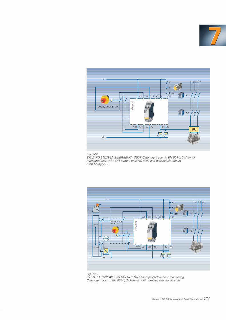
Fig. 7/56SIGUARD 3TK2842, EMERGENCY STOP, Category 4 acc. to EN 954-1, 2-channel,monitored start with ON button, with AC drive and delayed shutdown,Stop Category 1
Fig. 7/57SIGUARD 3TK2842, EMERGENCY STOP and protective door monitoring,Category 4 acc. to EN 954-1, 2-channel, with tumbler, monitored start
Y12Y11 Y32 Y34A1
K1
L+
Y22Y21 A2 14Y35 28
K1
3TK
28 4
2
K1
K2
K2
K2
1
M
L1 L2 L3
FU
EMERGENCY STOP
ON
Y12Y11 Y32 Y34A1
K1
L+
Y22Y21 A2 14Y35 28
K1
3TK
28 4
2
K1
K2
K2
K2
1
M
L1 L2 L3
EMERGENCYSTOP
open
closed
ON

7/30 Siemens AG Safety Integrated Application Manual
Fig. 7/58SIGUARD 3TK2841, cascaded with 3TK2842 for EMERGENCY STOP,2-channel, monitored start with ON button and protective door monitoring,2-channel, autostart, Category 4 acc. to EN 954-1
Fig. 7/59SIGUARD 3TK2842, light grid monitoring, 2-channel,autostart, Category 4 acc. to EN 954-1
Y12Y11 1 Y34A1
M
K1
3TK
28 4
1
K1K2
K2
L1 L2 L3L+
Y32
Y22Y21 14 24Y35 A2
Y12Y11 1 Y34A1 Y32
3TK
28 4
2
Y22Y21 14 24Y35 A2
K1 K2
Protective door
ON
EMERGENCYSTOP
FU
Y12Y11 1 Y34A1
K1M
Y22Y21 A2 14Y35 24
K1
3TK
28 4
2
K1
K2
K2
K2
L1 L2 L3L+
Y32
QSSD 1 2FU

Siemens AG Safety Integrated Application Manual 7/31
777
Fig. 7/60SIGUARD 3TK2842, contact mat, Category 3 acc. to EN 954-1, 2-channel, autostart
Fig. 7/61SIGUARD 3TK2850, 51, 52, internal circuit diagram, electronic basic unit with auxiliarycontactors, Category 3 acc. to EN 954-1
Y12Y11 1 Y34A1
K1M
Y22Y21 A2 14Y35 24
K1
3TK
28 4
2
K1
K2
K2
K2
L1 L2 L3
L+
Y32Contact mat
FU
Y12Y11 Y34A1 Y20
1 2
A2 Y21 Y22 Y33 A1 A2
3TK2850
3 4
K1
K2
33 4313
34 4414
2313 4333 7153 83
3TK
2852
2414 4434 7254 84
3113 43
3TK
2851
3214 44

7/32 Siemens AG Safety Integrated Application Manual
Fig. 7/62The electronic basic 3TK2850 device with auxiliary contactors,protective door monitoring, 2-channel, autostart, Category 3 acc. to EN 954-1
Fig. 7/63The electronic basic 3TK2850 device with auxiliary contactors, protective door monitoring,1-channel, autostart, Category 2 acc. to EN 954-1
3TK
28 5
0
open closed
N/-
A2
A1 Y33 Y34
Y11Y21
Y22Y12
L/+
14 24 34
13 23 33
K1
K2
3TK
28 5
0
open closed
N/-
A2
A1 Y33 Y34
Y11Y12
Y20Y21
L/+
14 24 34
13 23 33
K1
K2

Siemens AG Safety Integrated Application Manual 7/33
777
Fig. 7/64The electronic basic 3TK2850 device with auxiliary contactors, EMERGENCY STOP,1-channel, with additional ON button, Category 2 acc. to EN 954-1
Fig. 7/65The electronic basic 3TK2850 device with auxiliary contactors, EMERGENCY STOP,2-channel, Category 3 acc. to EN 954-1
3TK
28 5
0
N/-
A2
A1 Y33 Y34
Y11Y21
Y22Y21
L/+
14 24 34
EMERGENCY STOP
ON
13 23 33
K1
K2
3TK
28 5
0
N/-
A2
A1 Y34 Y33
Y11Y21
Y22Y12
L/+
14 24 34
EMERGENCY STOP
ON
13 23 33
K1
K2

7/34 Siemens AG Safety Integrated Application Manual
Fig. 7/66The electronic basic 3TK2850 device with auxiliary contactors, EMERGENCY STOP,2-channel, Category 4 acc. to EN 954-1 SIL 3
Fig. 7/673TK285.-.., EMERGENCY STOP, Category 4 acc. to EN 954-1, P-M switching inconjunction with operational control of a standard PLC (SIMATIC S7 300/ET200M),load current per enable circuit, 10 A
3TK
28 5
3
N/-
A2
A1 Y32
Y11Y21
Y22Y12
L/+
14 34 44
ON
EMERGENCY STOP
2
431 13 33 43
K1
K2
Y33 Y34
M
1L+
2019
17
13
15
11
2MK16
K9
2L+
M7
4
3
S7 300
0
M
109
7
3
5
1
1M
K1
K8
Backplanebus interface
Channel numberStatus display - green
• •
• •
••
• •
• •
• •
• •
••
• •
• •
Signal tothe PLC(3TK2852)
K21 K22 K23 •K36
14 24 34 44 54 72 84
13 23 33 43 53 71 83
24V DC 24V DC 24V DCM M
Y34 A1 A2Y33Y22Y21Y20Y12Y11A2A1
24V
K1•••
Kn
L/+
N/M
24V
DC
3TK2850, 51, 52
EMER-GENCYSTOP ON
K1
K2
K16
K36

Siemens AG Safety Integrated Application Manual 7/35
777
Fig. 7/683TK2853, internal circuit diagram, electronic basic device with auxiliary contactors,Category 4 acc. to EN 954-1
Fig. 7/69The electronic basic 3TK2853 device with auxiliary contactors, protective doormonitoring, 2-channel, autostart, Category 4 acc. to EN 954-1, SIL 3
Y12Y11 Y34A1 Y35A2 Y21 Y22 Y33 A1 A2
3TK2853
33 4313
34 4414
Y32
2431
3
4
21
5 6 7
K2
K1
3TK
28 5
3
open closed
N/-
A1
Y11Y12
Y22Y21
L/+
14 34 44
1 3 4
A2 2
13 33 43
K1
K2
Y34Y33Y32

7/36 Siemens AG Safety Integrated Application Manual
Fig. 7/70The electronic basic 3TK2853 device with auxiliary contactors,protective door monitoring, 1-channel, autostart, Category 2 acc. to EN 954-1, SIL 3
Fig. 7/71The electronic basic 3TK2853 device with auxiliary contactors, EMERGENCY STOP,1-channel, with additional EN button, Cat. 2 acc. to EN 954-1, SIL 3
3TK
28 5
3
N/-
A1
Y11Y12
Y22Y21
L/+
14 34 44
1 3 4
A2 2
Y35
open closed
13 33 43
K1
K2
Y32 Y34Y33
3TK
28 5
3
N/-
A1
Y11Y12
Y22Y21
L/+
14 34 44
Y32 Y34Y33 1 3 4
A2 2
Y35
ON
EMERGENCY STOP
13 33 43
K1
K2
Siemens AG Safety Integrated Application Manual 7/37
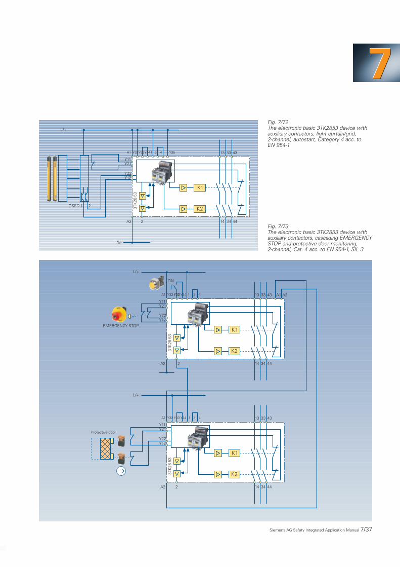
777Fig. 7/72The electronic basic 3TK2853 device withauxiliary contactors, light curtain/grid,2-channel, autostart, Category 4 acc. to EN 954-1
Fig. 7/73The electronic basic 3TK2853 device withauxiliary contactors, cascading EMERGENCYSTOP and protective door monitoring,2-channel, Cat. 4 acc. to EN 954-1, SIL 3
3TK
28 5
3
A1
Y11Y21
Y22Y12
L/+
14 34 44
1 3 4
A2 2
3TK
28 5
3
A1
Y11Y21
Y22Y12
L/+
14 34 44
Y32 3 4
A2 2
13 33 43
K1
K2
Y34 1Y33 A1 A2
EMERGENCY STOP
Y32 Y34Y33
Y33
13 33 43
K1
K2
Protective door
ON
3TK
28 5
3
N/-
A1
Y11Y21
Y22Y12
L/+
14 34 44
Y32 Y34Y33 1 3 4
A2 2
Y35
OSSD 1 2
13 33 43
K1
K2

7/38 Safety Integrated Application Manual Siemens AG
Typical application for
load feeder outgoing cables
• Six actuation units are monitored by
two EMERGENCY STOP switches
• The actuation equipment can either
be individual de-activated or in groups
using the protective doors
• During operation, the equipment is
switched-over using a PLC or a pushbutton.
EM
ERGENCY
S T O P
Protective doors
21 EM
ERGENCY
S T O P
654321
1 2 3 4
Conventional solution
• Conventional wiring =>
approx. 160 different solutions
• Complex installation =>
high costs => increased space
requirement
• Frequent faults
• No overload or short-circuit
protection
653321
1
Feedbackcircuit
Feedbackcircuit
Feedbackcircuit
Feedbackcircuit
EM
ERGENCY
S T O P
2
EM
ERGENCY
S T O P
Load feeders with Integrated Safety Technology
777
Safety Integrated Application Manual Siemens AG 7/39
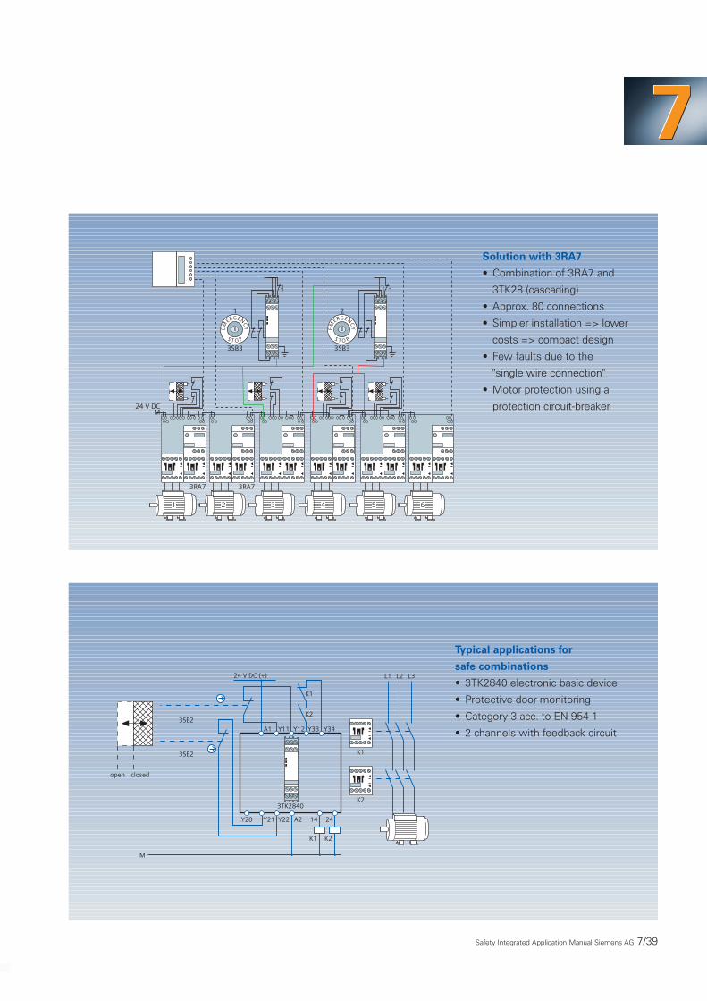
Solution with 3RA7
• Combination of 3RA7 and
3TK28 (cascading)
• Approx. 80 connections
• Simpler installation => lower
costs => compact design
• Few faults due to the
"single wire connection"
• Motor protection using a
protection circuit-breaker
2
24 V DCM
1
1 2 3 4 5 6
EM
ERGENCY
S T O P
EM
ERGENCY
S T O P
3RA7 3RA7
3SB3 3SB3
Typical applications for
safe combinations
• 3TK2840 electronic basic device
• Protective door monitoring
• Category 3 acc. to EN 954-1
• 2 channels with feedback circuit
3TK2840
24 V DC (+)
A1 Y11 Y12 Y33 Y34
K1
Y20
M
K1
Y21 Y22 A2 14 24
K1
K2
K2
K2
open closed
L3L2L1
3SE2
3SE2

7/40 Safety Integrated Application Manual Siemens AG
• 3TK2840 electronic basic device
• EMERGENCY STOP
• Category 2 acc. to EN 954-1
• 1 channel with feedback circuit
3TK2840
24 V DC (+)
A1 Y11 Y12 Y33 Y34
K1
ON
Y20
M
Y21 Y22 A2 14 24
K1
EM
ERGENCY
S T O P
L1 L2 L3
K1
3SB3
3SB3
• 3TK2840 electronic basic device
• EMERGENCY STOP
• Category 3 acc. to EN 954-1
• 2 channels with feedback circuit
24 V DC (+)
Y33 Y34
L1 L2 L3
K1
K2
Y21
Y22
A1
Y11
Y12
ON
EM
ERGENCY
S T O P
3TK2840
3SB3
3SB3
Y20
M
Y21 Y22 A2 14 24
K1

Safety Integrated Application Manual Siemens AG 7/41
777
Circuit examples for SIGUARD lightcurtains
Connection example, light curtainCategory 4 connected to a standardevaluation unit 3RG7847-4BB
Light curtain or light grid 3RG7842connected through 2 channels to the evaluation unit 3RG7847-4BB:
• Category 4 acc. to EN 954-1
• Manual start with monitoredstart button
• Contactor monitoring
Connection example, light curtainCategory 4 connected to an evalua-tion unit with muting function
A light curtain or light grid 3RG7842connected to the evaluation unit withmuting function 3RG7847-4BF:
• Category 4 acc. to EN 954-1
• Integrated muting function(e.g. with light barriers asmuting sensors)
• Manual start with dynamicallymonitored start button
• Dynamic contactor monitoring
7.1.3 Contactless Protective Devices
Fig. 7/74Connection example, light curtain Category 4 connected to a standard evaluation unit3RG7847-4BB
Fig. 7/75Connection example, light curtain Category 4 connected to an evaluation unit with mutingfunction
0 V
1)
+ 24 V
4 15 24 22 23 20 21 31 32 13 14 11
k2
k1
2
9 19 33 30 28 29 7 6 10 1
M1 M2 M3 M4T1 T2 S1 S2
+ 2
4 V
0 V
2.5 AT
Test AOPDs Muting sensors
RE
SE
T
MutingindicatorsState outputs Warn.Diagn. State
R-Output
6 AT
max
.
ED
M
Sta
rt
1 2
RS
232
S1-
S2
Mut
ing
Failu
re
Res
tart
inhi
bit
Con
tact
orm
onito
ring
Muting indicators24 V, 5 W max.
Possible common conductorfor fault/alarm active low
K2
1)K1
+24V
PE
Receiver
0 V1234567
+24V
PE
Sender
0 V1234
567
SIGUARDlight curtain/grid3RG7842
OS
SD
1 N
.O.
OS
SD
2 N
.O.
M1 M2 M3 M4
M-S
enso
r 1
Mut
ing
func
tion
Safety output
L+Ph
L-N
L+Ph
L-N
k1 k2 k1
k2
M-S
enso
r 2
M-S
enso
r 3
M-S
enso
r 4
SIGUARD 3RG7847-4BF
6 AT
max
.
s
2-channelenablecircuit
Use both contacts inthe enable circuit!K1 and K2 with positivelydriven contacts
1-channelenablecircuit
1) Provide suitable arc quenching
0 V
1)
SIGUARD 3RG7847-4BB
+ 24 V
S11 13 23
14 24
1 AT
K2
1)K1
+24V
Receiver
0 V1
23456
7
+24V
Sender
0 V1
234
5
6
7
SIGUARDlight curtain/grid3RG7842
N.O
.
N.O
.
Safetyoutput
k1 k2 k1
k2
s
A1(L+) S33 S34 S35 S31 S22
A2 (L-)
PE PE
Sta
rtR
esta
rt in
hibi
t
Con
tact
or m
onito
ring
6.3
AF
6.3
AF
CH1
CH2
32S21 S12
=
+
31
K2
K1
2-channelenablecircuit
1-channelenablecircuit
Use both contacts inthe enable circuit!K1 and K2 with positivelydriven contacts
1) Provide suitable arc quenching

7/42 Siemens AG Safety Integrated Application Manual
Fig. 7/76Connection example, light curtain Category 2 connected to a standard evaluation unit3RG7847-4BD
0 V
1)
SIGUARD 3RG7847-4BD
+ 24 V
4 15 24 22 23 13 14 11
k2
k1
2
9 7 6 10 1
T1 T2 S1 S2
+ 2
4 V
0 V
2.5 AT
Test AOPDs
RE
SE
T
Diagn. State
R-Output
6 AT
max
.
ED
M
Sta
rt
RS
232
Res
tart
inhi
bit
Con
tact
orm
onito
ring
K2
1)K1
+24V
Receiver
0 V
1234
567
+24V
Sender
0 V
1234
567
SIGUARDlight curtain/grid3RG7841
OS
SD
1 N
.O.
OS
SD
2 N
.O.
Safety output
L+Ph
L-N
L+Ph
L-N
k1 k2 k1
k2
6 AT
max
.
8 8
0 V
h I
Test input s
2-channelenablecircuit
Use both contacts inthe enable circuit!K1 and K2 with poitivelydriven contacts
1-channelenablecircuit
1) Provide suitable arc quenching
Fig. 7/77Connection example, light curtain Category 4 connected to an evaluation unit with cyclecontrol
2-channelenablecircuit
Use both contacts inthe enable circuit!K1 and K2 with poitivelydriven contacts
1-channelenablecircuit
The following appliesfor cycle mode:
Signal output 6 and LEDdisplay ”restart inhibitinterlocked” pulse, afterbeing released, with thenumber of requiredinterventions in theprotective field.
Only interventions longerthan 300 ms are acceptedfor control.
Machine contacts closeto the upper end positionopen OSSDs and cancelthe entered cycles.
1) Provide suitable arc quenching
+24 V
k k k
k
0 V
4 15 24 22 23
T1 T2 S1 S2
Res
et
ED
13 14 11 2
+24
V
Test AOPDs
L-N
L+Ph
2.5
AT
L-N
L+Ph
20 21
Con
tact
orm
onito
ring
Ena
ble
inhi
bit
Sta
rt 6 A
T m
ax.
k
k
Cyc
le c
ance
l
Pro
tect
ion
Sin
gle-
cycl
e
Machinecontact
Signal outputs
Two-
cycl
eS
elec
t
Cle
ar
7 6 10 1
OS
SD
1 N
.O.R-Output
Diagn. State
RS
232
0 V
K2
K1
9
OS
SD
2 N
.O.SIGUARD 3RG7847-4BH
19
S1-
S2
6 A
T m
ax.
State
1)
1)
+24V
PE
Receiver
0 V
1
2345
6
7
+24V
PE
Sender
0 V
1234
56
7
SIGUARDlight curtain/grid3RG7842
Connection example, light curtainCategory 2 connected to a standardevaluation unit 3RG7847-4BD
A light curtain 3RG7841 connected to the evaluation unit 3RG7847-4BD:
• Category 2 acc. to EN 954-1
• Cyclic testing of the light curtain
• Manual start with dynamicallymonitored start button
• Dynamic contactor monitoring
Connection example, light curtainCategory 4 connected to an evalua-tion unit with cycle control
A light curtain or grid 3RG7842/44connected through 2 channels to the evaluation unit 3RG7847-4BH:
• Category 4 acc. to EN 954-1
• Automatic single or two-cyclecontrol
• Manual start with dynamicallymonitored start button
• Dynamic contactor monitoring

Circuit examples for SIGUARD light barriers
Siemens AG Safety Integrated Application Manual 7/43
777
3RG7821-7BG00 3RG7821-7CD00
WH WHBN
3RG7821-7BG00 3RG7821-7CD00
X10X9 X12X11X6X5 X8X7A2A1 X1 X3X2 X4
X13 X14
0 V(internal)OUTIN
0 V(int.)OUT
TEST
X15 X16 X17 X18 X19 X20X22 Y1 X23
PNP-OUT
13 14 X21
K1
Contactor
3RG
7826
-1C
B1
+24 V(int.)IN
+24 V(int.)
+24 V(internal)
Externalfeedbackcircuits
+24V 0VStart
+24 V(int.)
IN OUT 0V(int.)
WH BNWH BNBN
Sender 2 Receiver 2Sender 1 Receiver 1
Fig. 7/78
7/44 Safety Integrated Application Manual Siemens AG
1 2 4 3 1 2 4 3 1 2 4 3 1 2 4 3
M3~
1 2 4 3 1 2 4 3 1 2 4 3 1 2 4 3
3RG7822-7CD003RG7822-7BG00
+24 V DC
A1 X4 X5 X6 X7 X8 13 23 39 41
Y1 Y2 + – 14 24 34 42
L1
Relay
24V T1 Q1 T2 Q2 RESTART Cont.M
RESTART
0 V
0V T3 Q3 T4 Q4 PM Indic.
K4
K5
N
Sender Receiver Sender Receiver
Sender Receiver Sender Receiver
Cont.M
3RG
7827
-1D
E2
UB OUT
UB OUT
0 V
X14A2 X9 X10 X11 X12 X13
X1 X2 X3 + –
SS
3RG... 3RG...
3RG... 3RG... 3RG... 3RG...
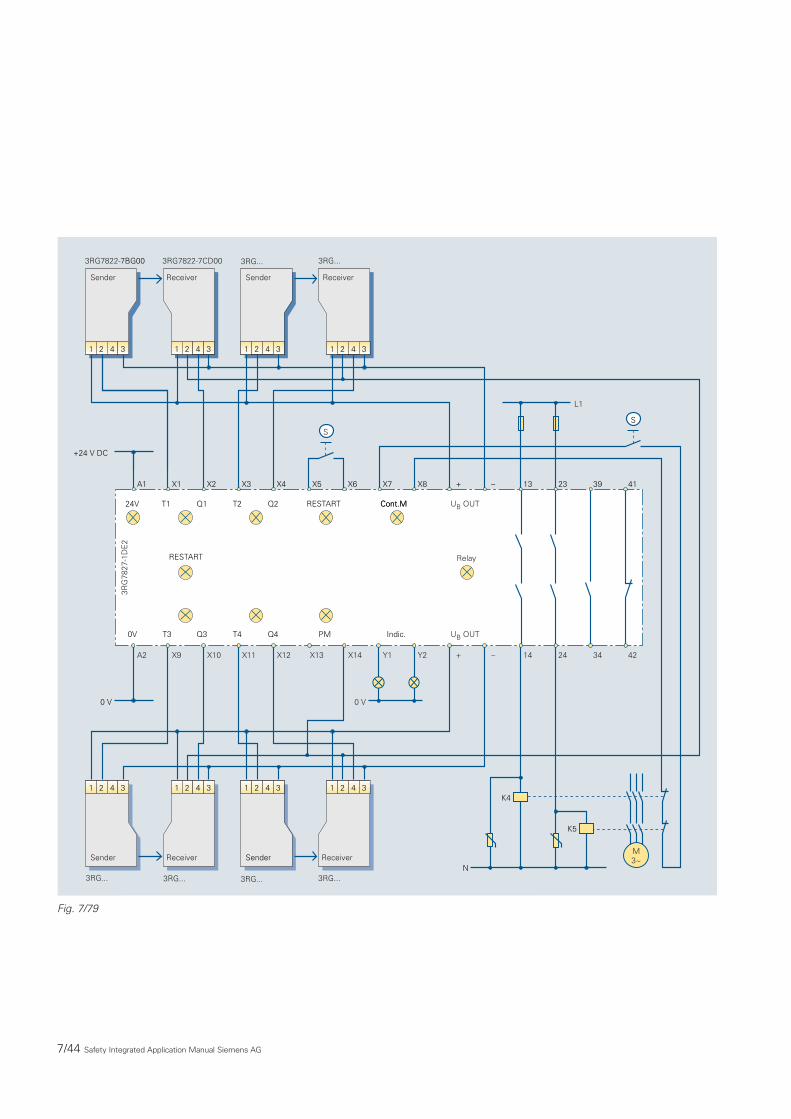
Fig. 7/79

LS4 laser scanner application
777
Safety Integrated Application Manual Siemens AG 7/45
• Start button for a manualrestart directly at the scanner(connection 2)
• Alarm output at connection 5(e.g. alarm lamp)
• The protective field is changed-over at connections 4, 6, 7 and 8
• The safe outputs are safelyprocessed (connections 11 and 12)when using an evaluation unit orfail-safe PLC
1 2 3 4 5 6 7 8 9 10 11 12 13 14 15
LS4 SIGUARD laser scanner
Evaluation unitor safety PLC
X1
1.25A mT
+ 24V0VPE
Connection example, LS4 SIGUARD laser scannerChanging-over the protective field, start button

7/46 Safety Integrated Application Manual Siemens AG
Connection example, LS4 SIGUARD laser scannerConnected to a standard 3RG7847-4BB evaluation unit
• Start button for a manualrestart directly at the scanner(connection 2)
• Fixed protective field pair 1(24 V always present at connection 4)
LS4 SIGUARD laser scanner
1 A
T
1 2 3 4 5 6 7 8 9 10 11 12 13 14 15
Safe output
0V
S11 S33 S34 S35 S31 S22
+24V
A2(L-) S12
CH1
CH2
SIGUARD 3RG7847-4BB
K1
K2 N.O
.
N.O
.
2414 32
13 23 31A1(L+)
1.25 AmT
K5*
*A suitable arc quenchingdevice must be provided
K4*
6.3
AF
6.3
AF
Neu
star
tspe
rre
Contactormonitoring
k4
k5
+ 24V0VPE
S21

777
Circuit examples with evaluationunit
SIGUARD switching strips, togetherwith the 3RG78 57-1BD evaluationunit, can be used as a safety systemup to Category 4 acc. to EN 954-1.Theevaluation electronics in the 22.5 mmenclosure is used to evaluate thetransmitter/receiver signal and to moni-tor the complete system for faults anderrors.
The power supply voltage of the evalu-ation unit is 24 V DC.Two relay outputs are available assafety-related outputs. A semiconduc-tor output can be used to issue asignal to a PLC. After the switchingstrip has been actuated, the devicemust be enabled using a manual startbutton, so that the system can restart.
Safety Integrated Application Manual Siemens AG 7/47
14 24
13 23
Safetyoutputs
K1 K2
Start button
X2 X3
Signaloutput
X1
12 Vcontroller
Safety-relatedsignal processing
A2(–)Safetyoutputs
K1 K2
K1
K2
K1
K2
A1(+)wh gn bn
3RG
7857
-1B
D
24 V DCpowersupply
Receiver Sender3RG7855-1R
Fig. 7/80
7.1.4 SIGUARD Switching Strips
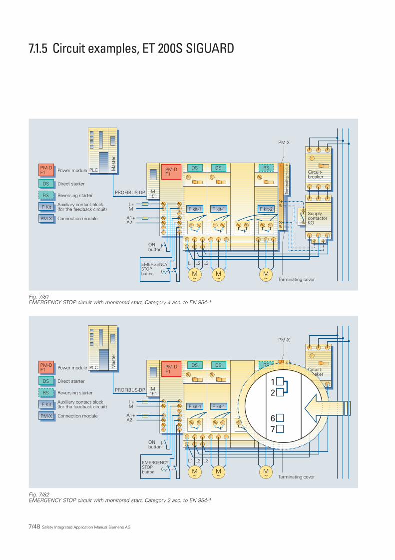
7.1.5 Circuit examples, ET 200S SIGUARD
7/48 Safety Integrated Application Manual Siemens AG
Fig. 7/82EMERGENCY STOP circuit with monitored start, Category 2 acc. to EN 954-1
Fig. 7/81EMERGENCY STOP circuit with monitored start, Category 4 acc. to EN 954-1
DS
F kit-1
M~
RS
F kit-2
M~
DS
F kit-1
M~
Power module
SupplycontactorKO
Circuit-breaker
PM-DF1
IM151
PM-X
PROFIBUS-DP
Mas
ter
L+M
A1+A2–
ONbutton
EMERGENCYSTOPbutton
PM-DF1
Direct starterDS
Reversing starterRS
Auxiliary contact block(for the feedback circuit)F Kit
Connection modulePM-X
Terminating cover
PLC
L1 L2 L3
Term
inat
ing
mod
ule
DS
F kit-1
M~
RS
F-Kit-2
M~
DS
F kit-1
M~
Circuit-breaker
PM-DF1
IM151
PM-X
PROFIBUS-DP
Mas
ter
L+M
A1+A2–
ONbutton
EMERGENCYSTOPbutton
PM-DF1
DS
RS
F Kit
PM-X
Terminating cover
PLC
L1 L2 L3
Term
inat
ing
mod
ule
12
67
Power module
Direct starter
Reversing starter
Auxiliary contact block(for the feedback circuit)
Connection module

777
Safety Integrated Application Manual Siemens AG 7/49
Fig. 7/84EMERGENCY STOP circuit arranged in a cascade
Fig. 7/83EMERGENCY STOP circuit in two groups
L1 L2 L3
PM-X
PM-DF1
EMERGENCY STOP 1 EMERGENCY STOP 2
A1+A2-
TM-PF30 S47-B1 TM-PF30 S47-B1
DS
F kit
M~
DS
F kit
M~
PM-DF1
IM151
PROFIBUS-DP
Mas
ter
L+M
A1+A2–
ONbutton
EMERGENCYSTOP button
PLC RS
F-KitSupplycontactorKO2
Circuit-breaker
PM-X
Terminating cover
Term
inat
ing
mod
ule
M~
M~
L1 L2 L3
SupplycontactorKO2
Circuit-breaker
F-Kit
DS
F kit
DS
F kit
L1 L2 L3
PM-X
PM-DF1
EMERGENCY STOP 2
A1+A2-
TM-PF30 S47-B1 TM-PF30 S47-B0
DS
F kit
M~
DS
F kit
M~
PM-DF1
IM151
PROFIBUS-DP
Mas
ter
L+M
A1+A2–
ONbutton
EMERGENCYSTOP button
PLC RS
F-KitSupplycontactorKO1
Circuit-breaker
PM-X
Terminating cover
Ter
min
atin
g m
odul
e
M~
M~
L1 L2 L3
SupplycontactorKO2
Circuit-breaker
F-Kit
DS
F kit
DS
F kit
EMERGENCY STOP 1

7/50 Safety Integrated Application Manual Siemens AG
Fig. 7/85EMERGENCY STOP circuit arranged in a cascade with delayed shutdown (Stop Category 1)
L1 L2 L3
PM-X
PM-DF3
EMERGENCY STOP 1
Stop Cat. 1Cat. 3
TM-PF30 S47-B1 TM-PF30 S47-C0
Stop Cat. 0Cat. 4
DS
F kit
M~
DS
F kit
M~
PM-DF1
IM151
PROFIBUS-DP
Mas
ter
L+M
A1+A2–
ONbutton
EMERGENCYSTOP button
PLC RS
F kitSupplycontactorKO1
Circuit-breaker
PM-X
Terminating cover
Term
inat
ing
mod
ule
M~
M~
L1 L2 L3
DS DS
A2+A1-
SupplycontactorKO2
Circuit-breaker
F kit

777
Safety Integrated Application Manual Siemens AG 7/51
Fig. 7/86EMERGENCY STOP combined with protective door
TM-PF30 S47-B1 TM-PF30 S47-B0
PM-DF1
IM151
PROFIBUS-DP
Mas
ter
L+M
A1+A2–
ONbutton
EMERGENCYSTOPbutton
PLC DS
F kit
M~
RS
F kit
M~
DS
F kit
M~
PM-X
DS
F kit
M~
open closed
Protective door
DS
SupplycontactorKO2
Circuit-breaker
PM-X
Terminating cover
L1 L2 L3
Term
inat
ing
mod
ule
PM-DF2

7/52 Safety Integrated Application Manual Siemens AG
Fig. 7/88Integrated in an external EMERGENCY STOP circuit, Category 4 acc. to EN 954-1
Fig. 7/87One EMERGENCY STOP circuit for several ET 200S rails
DS
F kit
M~
DS
F kit
M~
PM-DF1
IM151
PROFIBUS-DP
Mas
ter
L+M
A1+A2–
ONbutton
EMERGENCYSTOPbutton
PLC
L1 L2 L3
SupplycontactorKO1
Circuit-breaker
PM-X
Terminating cover
Term
inat
ing
mod
ule
DS
F kit
M~
DS
F kit
M~
DF DF
PM-DF4
IM151
L+M
A1+A2–
L1 L2 L3
SupplycontactorKO2
Circuit-breaker
PM-X
Terminating cover
Term
inat
ing
mod
ule
TM-PF30 S47-B1 TM-PF30 S47-C1
EMERGENCY STOP 1
DS
F kit-1
M~
RS
F kit-2
M~
DS
F kit-1
M~
PM-XPM-D
AUX2AUX3
EMERGENCYSTOPbutton
ONbutton
3TK2823
SupplycontactorKO
Circuit-breaker
Terminating cover
L1 L2 L3
Ter
min
atin
g m
odul
e
IM151
PROFIBUS-DP
Mas
ter
PLC
L+M
A1+A2–
PM-XA1+

777
Safety Integrated Application Manual Siemens AG 7/53
Fig. 7/90SIMATIC ET 200S SIGUARD and AS-i Safety at Work
Fig. 7/89Integrated in an external EMERGENCY STOP circuit, Category 2 acc. to EN 954-1
DS
F kit-1
M~
RS
F kit-2
M~
DS
F kit-1
M~
PM-XPM-D
AUX2AUX3
EMERGENCYSTOPbutton
ONbutton
3TK2823
Circuit-breaker
Terminating cover
L1 L2 L3
Ter
min
atin
g m
odul
e
IM151
PROFIBUS-DP
Mas
ter
PLC
L+M
A1+A2–
PM-XA1+
DS
F kit-1
M~
RS
F kit-2
M~
DS
F kit-1
M~
PM-XPM-D
AUX2AUX3
ONbutton
Shutdown circuit
Feedback circuit
AS-iSafetyMonitor
EMERGENCYSTOP switch 1
EMERGENCYSTOP switch 2
EMERGENCYSTOP switch 3
EMERGENCYSTOP switch 4
EMERGENCYSTOP switch 5
SupplycontactorKO
Circuit-breaker
Terminating cover
L1 L2 L3
Term
inat
ing
mod
ule
IM151
PROFIBUS-DP
Mas
ter
PLC
L+M
A1+A2–
PM-X
A1+
Category 4(EN 954-1) – separate shutdown groups are also possible

7/54 Safety Integrated Application Manual Siemens AG
Fig. 7/92EMERGENCY STOP circuit with integrated external actuators
Fig. 7/91EMERGENCY STOP circuit with integrated pneumatic valves
DS
F kit-1
M~
RS
F kit-2
M~
DS
F kit-1
M~
SupplycontactorKO
Circuit-breaker
Term
inat
ing
mod
ule
PM-E
DO DO DOPM-DF1
IM151
PM-X
PROFIBUS-DP
Mas
ter
L+M
A1+A2–
ONbutton
EMERGENCYSTOPbutton
PLC
L1 L2 L3
24V
Category 4 acc. to EN 954-1 Cat 1
M~
DS
F kit-1
M~
RS
F kit-2
M~
DS
F kit-1
M~
Term
inat
ing
mod
ule
PM-E
DO DO DOPM-DF1
IM151
PM-X
PROFIBUS-DP
Mas
ter
L+M
A1+A2–
ONbutton
EMERGENCYSTOPbutton
PLC
L1 L2 L3
Category 4 acc. to EN 954-1 Cat 4
SupplycontactorKO
Circuit-breaker

This section shows you the possibili-ties of achieving Safety ClassesAK4/SIL2/Cat.3 and AK6/SIL3/Cat.4using the F I/O in S7-300F and S7-400F/FH.This information refers to the F I/O of the SIMATIC S7 range - this means F-SMs S7-300 and F modules ET 200S.
How is the safety class achieved for F inputs?
For F inputs, the required Safety Classis achieved by the type of transmitterevaluation.This means that SafetyClass AK4/SIL2/Cat.3 or AK6/SIL3/Cat.4. is defined by how the transmit-ter is connected-up.
777How is the Safety Class achievedwith F outputs?
For F outputs, the required SafetyClass is achieved by the way in whichthe test signals are connected tothe F I/O.
Evaluating transmitters for F digitalinputs
For F digital inputs, the requiredSafety Class is achieved by the type of transmitter evaluation.
Safety Integrated Application Manual Siemens AG 7/55
Table: Safety Classes which can be achieved for F digital inputs
7.2 Controllers: Fail-safe controls
7.2.1 Circuit examples for S7-300F
Achieved by
Acc. to IEC 61508 Acc. to DIN V 19250 Acc. to EN 954-1 Transmitter evaluation
SIL2 AK4 Cat. 3 1-from-1 evaluation
SIL3 AK5,6 Cat. 4 2-from-2 evaluation
Safety Classes

Example: A transmitter connectedto an F-DI through 1 channel(AK4/SIL2/Cat.3)
The connection schematic for an SM326, DI 24 x 24V DC for a 1-from-1evaluation of the transmitter is shownin the following diagram.The transmit-ter is supplied from the F I/O.AK4/SIL2/Cat.3 can be achieved usingthis connection.
Example: A transmitter connectedto an F-DI through 1 channel(AK6/SIL3/Cat.4)
The connection schematic for an SM326, DI 24 x 24V DC for a 2-from-2evaluation of the transmitter is shownin the following diagram.The transmit-ter is supplied from the F I/O.AK6/SIL3/Cat.4 can be achieved usingthis connection as long as a suitablyqualified transmitter is used.
Example: A transmitter connectedto an F-DI through 2 channels(AK6/SIL3/Cat.4)
The connection schematic for an SM326, DI 24 x 24V DC for a 2-from-2evaluation of the transmitter is shownin the following diagram.AK6/SIL3/Cat.4 can be achieved usingthis connection.
Example: An antivalenttransmitter (2-channel) connectedto an F-DI (AK6/SIL3/Cat.4)
The connection schematic for an SM326, DI 24 x 24V DC with antivalenttransmitter (2-from-2 evaluation) isshown in the following diagram.AK6/SIL3/Cat.4 can be achieved withthis connection.
7/56 Safety Integrated Application Manual Siemens AG
Example: Wiring schematic for a transmitter connected to an F-DI (2-from-2) through 2 channels)
Digital inputmodule
1L+
1M
Vs
DILeft: Channels 0…11
Right: Channels 0…11 Vs
DI
Example: Connection schematic for an anti-valent transmitter connected to an F-DI (2-from-2) through 2 channels
Digital inputmodule
1L+
1M
Vs
DI
DI
Left: Channels 0…11
Right: Channels 0…11
Example: Wiring schematic for a transmitter connected to an F-DI (1-from-1) through 1 channel
Digital inputmodule
1L+
1M
Vs
DI
Example: Wiring schematic for a transmitter connected to an F-DI (2-from-2) through 1 channel)
Left: Channels 0…11
Right: Channels 0…11
Digital inputmodule
1L+
1M
Vs
DI
DI
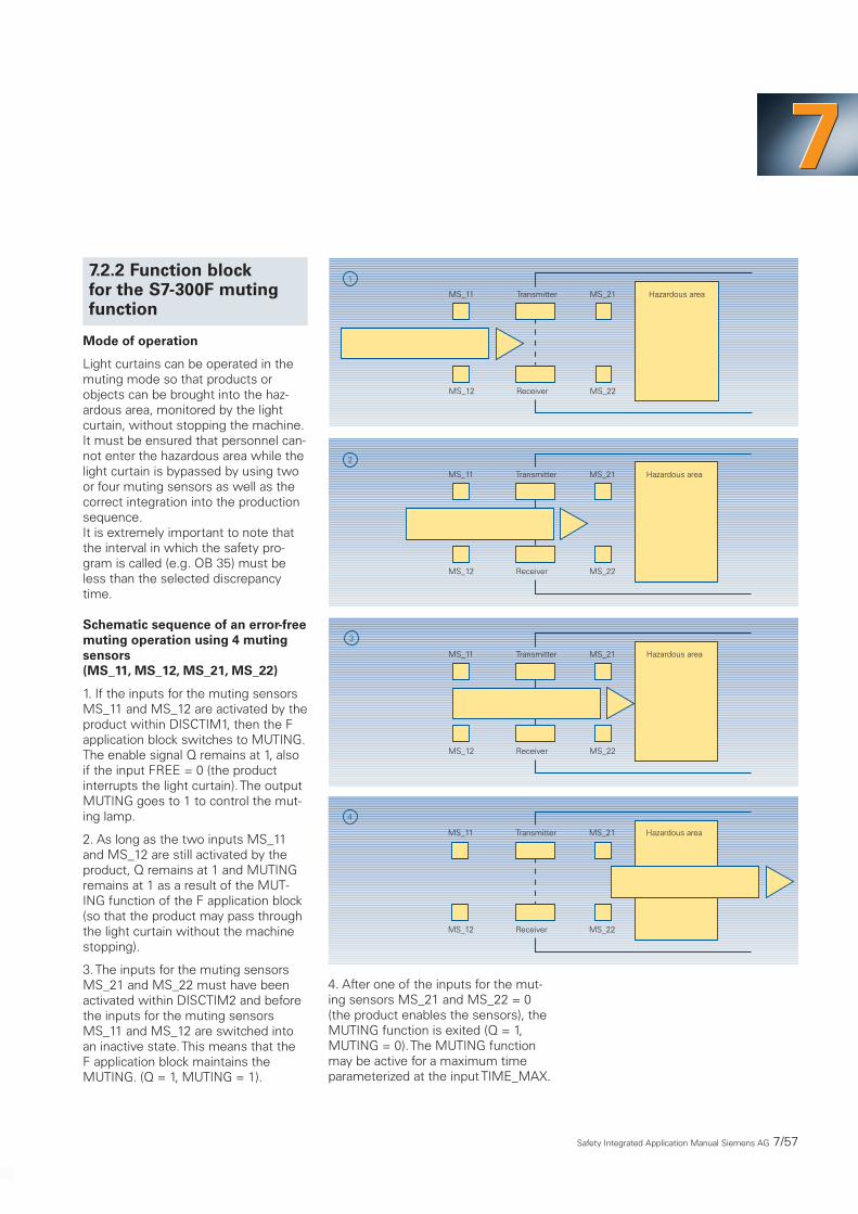
Mode of operation
Light curtains can be operated in themuting mode so that products orobjects can be brought into the haz-ardous area, monitored by the lightcurtain, without stopping the machine.It must be ensured that personnel can-not enter the hazardous area while thelight curtain is bypassed by using twoor four muting sensors as well as thecorrect integration into the productionsequence.It is extremely important to note thatthe interval in which the safety pro-gram is called (e.g. OB 35) must beless than the selected discrepancytime.
Schematic sequence of an error-freemuting operation using 4 mutingsensors(MS_11, MS_12, MS_21, MS_22)
1. If the inputs for the muting sensorsMS_11 and MS_12 are activated by theproduct within DISCTIM1, then the Fapplication block switches to MUTING.The enable signal Q remains at 1, alsoif the input FREE = 0 (the productinterrupts the light curtain).The outputMUTING goes to 1 to control the mut-ing lamp.
2. As long as the two inputs MS_11and MS_12 are still activated by theproduct, Q remains at 1 and MUTINGremains at 1 as a result of the MUT-ING function of the F application block (so that the product may pass throughthe light curtain without the machinestopping).
3.The inputs for the muting sensorsMS_21 and MS_22 must have beenactivated within DISCTIM2 and beforethe inputs for the muting sensorsMS_11 and MS_12 are switched intoan inactive state.This means that the F application block maintains the MUTING. (Q = 1, MUTING = 1).
777
4. After one of the inputs for the mut-ing sensors MS_21 and MS_22 = 0(the product enables the sensors), theMUTING function is exited (Q = 1,MUTING = 0).The MUTING functionmay be active for a maximum timeparameterized at the input TIME_MAX.
Safety Integrated Application Manual Siemens AG 7/57
7.2.2 Function block for the S7-300F mutingfunction
Hazardous areaMS_21
MS_22
Transmitter
Receiver
MS_11
MS_12
1
Hazardous areaMS_21
MS_22
Transmitter
Receiver
MS_11
MS_12
2
Hazardous areaMS_21
MS_22
Transmitter
Receiver
MS_11
MS_12
3
Hazardous areaMS_21
MS_22
Transmitter
Receiver
MS_11
MS_12
4

Timing diagram for error-free muting using 4 muting sensors
DISCTIM1 and DISCTIM2 are discrep-ancy times for sensor pairs 1 and 2.
7/58 Safety Integrated Application Manual Siemens AG
FREE
MS_11
MS_12
MS_21
MS_22
ACK
MUTING
Q
FAULT
ACK_REQ
t < DISCTIM2
t < TIME_MAX
t < DISCTIM1

777
Fig. 7/93Stop Category 0, 2-channel, with feedback circuit; Category 3 acc. to EN 954-1; Function with a motor coasting down
N/–
14
13
24
23
K1M3~
K1
A2
EMER-GENCYSTOP
A1
P24 V DCM DC
Y1 Y2
ON
L/+N/–
U2 V2 W2SIMOVERT MASTERDRIVES
ControlmoduleCU
PV
M
P24V
Option K80X533
X101
K1
L1L2L3PE
X: Digital input,assigned to OFF2P556i001 and i002
U1 V1 W1
Separatelyprotected routing
3TK
2824
1)
Loop in check-back signals fromprotective devices,e.g. door interlocks,light curtains
1)
1243
Communi-cationsmodule,e.g. CBP
X
Drive inverter
This section describes the circuitexamples using the drive systemsSIMOVERT MASTERDRIVES andSIMODRIVE 611 universal for applica-tions involving variable-speed driveswith AC motors.
These examples show possibilities of implementing the various solutions.The solution required for the machinemust be aligned to the particularmachine function.This results inindividual parameter assignments orcontrol commands for applicationsassociated with stop Category 1.
Using the “safe standstill” function,the drive pulses are cancelled thuspreventing the drive from undesirablystarting.
The solutions which are shown can,from the actual principle, also beimplemented using other drivesystems. However, the appropriateinformation/instructions in the docu-mentation describing the variousproducts must be carefully observed(also refer to the Certificate in Section8.6.3)
SIMOVERT MASTERDRIVES Vector Control Catalog DA 65.10
SIMOVERT MASTERDRIVES Motion Control Catalog DA 65.11
SIMODRIVE 611Catalog NC 60.1 and NC 60.2
7.3 Motion Control Systems: Safe Motion Control
7.3.1 Application exam-ples for EMERGENCYSTOP Category 0
Safety Integrated Application Manual Siemens AG 7/59

7/60 Siemens AG Safety Integrated Application Manual
Fig. 7/94Stop Category 1, 2-channel, with feedback circuit, Category 3 acc. to EN 954-1;Function where the motor is shut down along the torque limit in a controlled fashion.
13 23
14 24
N/–
32 44
31 43
54
53
K1
K1
Y11
A2Y21 Y22
EMER-GENCYSTOP
A1 Y12
24 V DCM DC
Y33
PE
PE
Y34
H1
ON
L/+N/–
X533
K1
L1L2L3PE
U1 V1 W1
Y10
3TK
2827
M3~
U2 V2 W2SIMOVERT MASTERDRIVES
ControlmoduleCU
PV
M
P24V
Option K80X533
X101
X: Digital input,assigned to OFF2P556i001 and i002
Loop in check-back signals fromprotective devices,e.g. door interlocks,light curtains
1)
1243
Communi-cationsmodule,e.g. CBP
1)
X
Y
Drive inverter
X: Digital input,assigned to OFF3P559i001 and i002
7.3.2 Application exam-ples for EMERGENCYSTOP Category 1

Structure acc. to EN 954-1 controlcategory 3 and EN1037
The drive is shut down according tothe stop function, Category 1 acc. toEN 60204-1.
Siemens AG Safety Integrated Application Manual 7/61
777By implementing as a higher-levelcircuit using contacts, the “Safe stand-still” function is even guaranteed forerroneous behavior or if the PLC fails.For an EMERGENCY SWITCHING-OFF,the drive is electrically isolated fromthe line supply.For this type of connection, the inter-nal line contactor of the supply unitonly drops-out if the internal safetyrelay functions erroneously.
Fig. 7/95EMERGENCY SWITCHING-OFF and EMERGENCY STOP, Stop Category 1 acc. to EN 60204,2-channel with feedback circuit, control Category 3 acc. to EN 954-1
7.3.3 Application examplesfor EMERGENCY SWITCH-ING-OFF and EMERGENCYSTOP Category 1
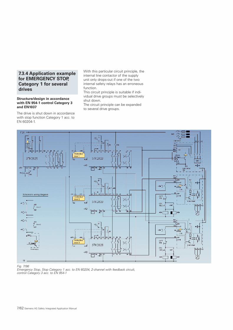
Structure/design in accordancewith EN 954-1 control Category 3and EN1037
The drive is shut down in accordancewith stop function Category 1 acc. toEN 60204-1.
7/62 Siemens AG Safety Integrated Application Manual
With this particular circuit principle, theinternal line contactor of the supplyunit only drops-out if one of the twointernal safety relays has an erroneousfunction.This circuit principle is suitable if indi-vidual drive groups must be selectivelyshut down.The circuit principle can be expandedto several drive groups.
7.3.4 Application examplefor EMERGENCY STOP,Category 1 for severaldrives
Fig. 7/96Emergency Stop, Stop Category 1 acc. to EN 60204, 2-channel with feedback circuit,control Category 3 acc. to EN 954-1

Siemens AG Safety Integrated Application Manual 7/63
777