circuit breaker calibration - ecesd.engr.uconn.edu · spring 2016 senior design ... leader in the...
TRANSCRIPT

Circuit Breaker Calibration
ECE 4902 Senior Design II
Spring 2016
Senior Design Final Report
Senior Design Team 1601 Philip Simonin (EE) Tyler Lyon (EE) Kyle Weber (EE) Louis LeBlanc (EE)
Advisor: Ali Gokirmak
Sponsor: Carling Technologies
Contacts: John Lach, Marek Szafranski, Mike Fasano, and Stephen Simonin

Carling Technologies Carling Technologies headquarters is located in Plainville, Connecticut. Founded in
1920, the company has established itself among the world's largest manufacturers of switches and controls, circuit protection, power distribution units, multiplexing power distribution system, and custom solutions for various applications.Their products serve in the industries of transportation, marine, renewable energies, telecom/datacom, and the military. Carling is capable of being this versatile in part due to their engineering research and new product development located at the main offices in Plainville. The company utilizes their Texas, Mexico, and China facilities to mass produce the various components they create and allow them to be a global leader in the electrical industry. Among their products are the company’s hydraulic circuit breakers created with various capabilities in mind. The circuit breakers which are mass produced require adjustment and calibration before they are delivered to customers for application in the real world. Summary
The enhancement and automation of the calibration process is what Team 1601 has been tasked with for the senior design project. The circuit breakers assigned to the team are Carling’s DC ASeries magnetic breakers. These are ideal for precision operation in OEM markets requiring general purpose and full load amp application due to their compact and temperature stable design. They are available with a choice of time delays, terminals, actuator styles, a wide range of standard colors, and imprinting. The current process has a high margin of error since it is done manually, requiring added time to complete the calibration. The task set before the team is to create an operational model or concept which is capable of conducting the process of calibration and eliminate high margins of error and reducing the time needed to complete the calibration. Objectives
The proposed solution that Team 1601 has devised involves designing a module implementing a microprocessor which is controlled by a current pickup type of detection. With a closed circuit (breaker contacts conducting), the motor will be signaled to turn clockwise. The motor is connected to an adjustment screw located within the breaker. The adjustment screw changes the amount of spring tension adjustment of the circuit breaker actuation arm. Adjustments are to be made until the required threshold for the tripping of the breaker is reached. The project was created in an effort to design and implement a functioning circuit breaker calibration unit which will adjust circuit breakers to trip at their designated point. Current company standards require this process to be completed in approximately 20 seconds and in order to improve efficiency and accuracy of calibration, will become semiautomated with this unit. Approach
Beginning this project required research about the operation of circuit breakers and what the calibration was really adjusting. The process of tripping occurs with an induced electromagnetic field acting on a metal cylinder within the breaker. Inside the this cylinder is a steel plunger submerged within a viscous silicone fluid. When the core reaches the top of the coil, the induced magnetic field pulls on an actuation arm that is spring loaded to a specific

tension. When the force is great enough to pull the actuation arm down, the breaker trips and opens circuit. The calibrating of these breakers is accomplished by adjusting the level of spring tension against the actuation arm via an adjustment screw as shown in figure 1.
Figure 1. Internal layout of a Carling circuit breaker highlighting the adjustment screw and the spring that adjusts the force on the actuation arm. The calibration of a breaker involves precise changes to the adjustment screw in order to increase or decrease current trip point.
Altering the tension changes the breakers allowed current let through to the magnetic sense coil which responds with an increase or decrease of applied electromagnetic force on the actuation arm, meaning a higher or lower current trip point. Completing the calibration in a more automated and efficient process having a margin of error closer to +/10% will require a few crucial components. The automated control is to be accomplished with a PSoC (Programmable System on Chip) made by Cypress, stepper motor and driver, solenoid to prevent breaker trip when engaging and transitioning between loads, pneumatic rig, as well as logic and sensory detection within the PSoC. All components will be combined to complete the calibration of a circuit breaker and any needed offsets for DC breakers of 5, 10, 15, and 20 Amp ratings with the potential for being applied to other breakers in the future.
Specifications Circuit Breaker Specifications:
● ASeries Circuit Breakers
● 5, 10, 15, 20A rated breakers
● Max Voltage Current Rating: 80 VDC
● Resistance values from Line to Load Terminal
● Single Pole ● 10,000 ON/OFF
operations @ 6 per min. ● Trip free
PSoC capabilities [1] [2]:
● 32bit MCU Subsystem ○ 48MHz ARM® Cortex®M0 CPU ○ Up to 128KB Flash, 16KB SRAM ○ DMA Controller ○ 2x CAN 2.0
● CapSense® with SmartSense™ Autotuning ○ Cypress Capacitive SigmaDelta™ (CSD) controller ○ CapSense supported on up to 55 pins
● Programmable Analog Blocks ○ 2x LowPower Comparators (CMP) ○ 4x LowPower Op Amps ○ 1x 12bit, 1Msps SAR ADC ○ 4x IDACs (2x 8bit, 2x 7bit) ○ 1 55 Channel Analog Multiplexer
● Programmable Digital Blocks ○ 4x Universal Digital Blocks (UDBs) ○ 8x 16bit TCPWM blocks ○ 4x SCBs: I2C M/S, SPI M/S, UART
● 2x Controller Area Network (CAN 2.0) Controllers ● Packages:48pin LQFP, 64pin TQFP (0.8mm pitch), 64pin TQFP (0.5mm pitch), 68pin
QFN H bridge stepper motor driver [3] [4]:
● Bipolar Microstepping Driver ● 2A/Phase Max ● 1.41.7A/Phase w/o Heatsink ● Max Motor Drive Voltage: 30V ● Onboard 5V/3.3V Regulation
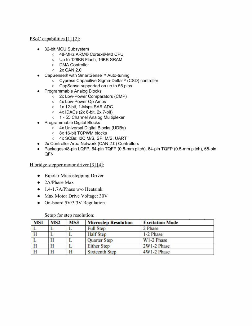
Setup for step resolution:

Figure 2. Cypress 4200 control chip with data pins highlighted in blue and supply pins in green.
Cypress’ 4200 chipset allows for up to 36 I/O pins to be used. This provides the ability to design a circuit with a wider variety of digital, analog, or combination of these capabilities. Due to the PSoC design and potential, it was chosen to be the controller for the calibration unit. In figure 2 are the pins used in the development of the prototype allowing for considerable expansion if necessary. The possibility of using more of the controller's analog or digital devices may occur depending on Carling’s need in the future and if/when adjustments are required when applied to other product lines or further testing reveals necessary changes. Process and Method of Operation
The first requirement was that of having a retaining unit to hold the breaker and associated equipment to make calibration possible. In an effort to accomplish this task, the pneumatic rig in figure 4 maintains position of the breaker in the X, Y, and Z axes while completing the circuit with two copper cylinders attached to the breaker’s external contacts. The calibration of the breaker requires a method of retainment as well as the ability to make adjustments to the device while current is applied. The retainment and contact portion of the rig
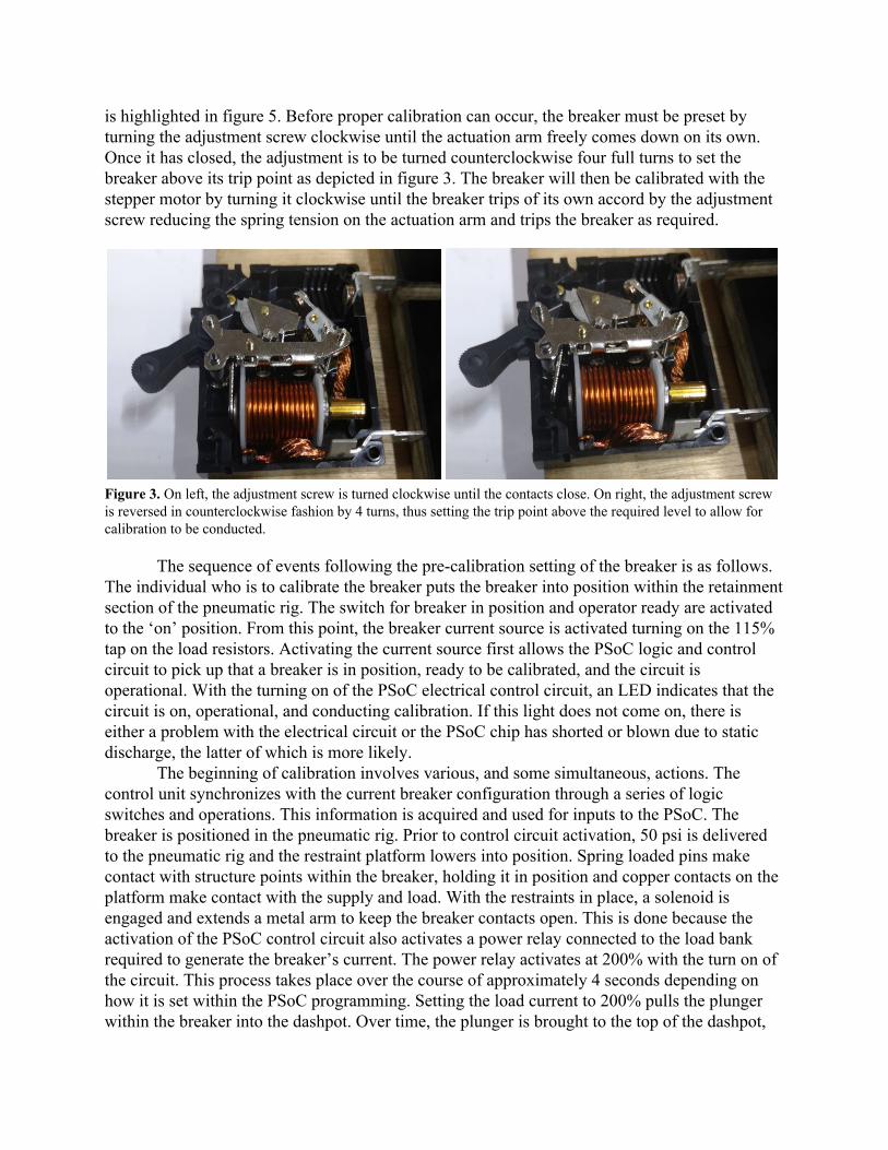
is highlighted in figure 5. Before proper calibration can occur, the breaker must be preset by turning the adjustment screw clockwise until the actuation arm freely comes down on its own. Once it has closed, the adjustment is to be turned counterclockwise four full turns to set the breaker above its trip point as depicted in figure 3. The breaker will then be calibrated with the stepper motor by turning it clockwise until the breaker trips of its own accord by the adjustment screw reducing the spring tension on the actuation arm and trips the breaker as required.
Figure 3. On left, the adjustment screw is turned clockwise until the contacts close. On right, the adjustment screw is reversed in counterclockwise fashion by 4 turns, thus setting the trip point above the required level to allow for calibration to be conducted.
The sequence of events following the precalibration setting of the breaker is as follows.
The individual who is to calibrate the breaker puts the breaker into position within the retainment section of the pneumatic rig. The switch for breaker in position and operator ready are activated to the ‘on’ position. From this point, the breaker current source is activated turning on the 115% tap on the load resistors. Activating the current source first allows the PSoC logic and control circuit to pick up that a breaker is in position, ready to be calibrated, and the circuit is operational. With the turning on of the PSoC electrical control circuit, an LED indicates that the circuit is on, operational, and conducting calibration. If this light does not come on, there is either a problem with the electrical circuit or the PSoC chip has shorted or blown due to static discharge, the latter of which is more likely.
The beginning of calibration involves various, and some simultaneous, actions. The control unit synchronizes with the current breaker configuration through a series of logic switches and operations. This information is acquired and used for inputs to the PSoC. The breaker is positioned in the pneumatic rig. Prior to control circuit activation, 50 psi is delivered to the pneumatic rig and the restraint platform lowers into position. Spring loaded pins make contact with structure points within the breaker, holding it in position and copper contacts on the platform make contact with the supply and load. With the restraints in place, a solenoid is engaged and extends a metal arm to keep the breaker contacts open. This is done because the activation of the PSoC control circuit also activates a power relay connected to the load bank required to generate the breaker’s current. The power relay activates at 200% with the turn on of the circuit. This process takes place over the course of approximately 4 seconds depending on how it is set within the PSoC programming. Setting the load current to 200% pulls the plunger within the breaker into the dashpot. Over time, the plunger is brought to the top of the dashpot,

inducing an electromagnetic field strong enough to trip the breaker. This is only one half of what is required.
Upon expiration of the 4 second timeframe at 200%, the power relay opens, switching the load to 115%, and leaving the solenoid engaged between the contacts to avoid instant tripping between load switching. Simultaneously, the amount of current let through in the breaker is observed as a voltage from a shunt resistor and monitored by two methods: A calibrated DMM for operator reference and the PSoC for operational observation. Based on this reading, the PSoC will signal a stepper motor to begin turning clockwise, decreasing the amount of current being passed through the breaker. The solenoid overlaps engagement when the load is switched from 200% to 115% for approximately .5 to .75 seconds while the motor is engaged and turning clockwise. The motor continues clockwise motion until the breaker naturally trips due to the induced electromagnetic field. When the breaker trips, the PSoC conducts a reverse operation in the counterclockwise direction for approximately 30 ms to account for circuit delays interfering with the shut off of the motor in the clockwise direction. Upon completion of these sequences, the PSoC circuit turns on a second LED indicating that the circuit calibration is complete. This process is conceptual in nature and meant to prove that the process is an accomplishable task. Modifications may indeed need to be made to perfect the prototype.
The overall design of the calibration unit is setup with the PSoC and motor driver for control operations while the stepper motor is handheld in place due to the lack of a better method. The original plan involved attaching the motor and its flat head extension to the lower platform of the pneumatic rig represented in figure 4. Establishing a 200% load of rated current for the 20 amp breakers using a 5 VDC high current power supply requires 40 amps through the breaker and a generation of 200 W peak to be sustained for a maximum of 5 seconds. Due to the power dissipation of the breaker loads, the load bank was separated from the rig and electrical control equipment and has a fan available to allow for the cooling of the load bank while under test.
Figure 4. On the left is a view of the pneumatic calibration rig connected to PSoC control. It has vertical movement and delivers a downforce of 50 psi to hold the breaker in position under load. On the right, circled in green are horizontal spring loaded constraints. The adjustment screw circled in blue. The two copper cylinders circled in orange provide current while under test.

Figure 5. Block diagram of calibration unit and layout of components. Sequencing of calibration process indicated on right side of diagram.
The Top Design of the PSoC layout seen in figure 6 indicates the utilized pins for the current prototype. The Relay_Load (P2(4)), is what uses a 5 VDC signal to drive a high power relay via an darlington pair style optocoupler to control and switch between 115% or 200% load. The active Alive pin (P2(1)) indicates to the operator that the PSoC is still on and functioning as required and when off, indicates error in function or a malfunctioning PSoC. The stepper motor is controlled with clocked pulses intervalled between 1 and 10 microseconds by setting P2(2)) high or low through the use of a PWM. This message signal is sent to the Big Easy Stepper Driver, an H bridge driving board, and acts on the enable pin. Depending upon the speed of adjustment required, the PWM is adjustable. The rule to be considered as directed by the company is to not exceed 1 revolution per 3 second interval. Exceeding this limitation will generate a drastic adjustment to the breaker which will lead to inaccurate calibration. The PWM value(s) are subject to change when applied to other breaker series.
The PSoC’s PWM pulsed signal acts on the enable pin on the H bridge driver controlling the motor operation. A reverse relay motor drive (P2(3)) is available as well as functional to correct for overshooting due to electrical and mechanical time delays encountered when turning of the stepper motor. Its purpose is to not only account for overtravel of the adjustment screw, but also adjust the trip point back to the initial trip point setting of the adjustment screw. P0(7) acts as a system clock and acts as a reference for the operation of the internal functions of the PSoC. P0(4) delivers a 5VDC signal to drive an optocoupler to the solenoid which interjects its arm between the internal contacts of the breaker during 200% resistive load. The arm remains momentarily between the contacts during the transition from 200% to 115% in order to prevent an instant trip during this load transfer sequence.

Figure 6. Top Design of PSoC digital and analog operations.
The Top Design in figure 6 demonstrates the currently programmed functional operation of the PSoC. The input pins are configurable as needed. For this application, they are defined as high impedance analog inputs. The provision of an analog internal timer is established on P2(7)at 1 KHz and is used to provide the system with a baseline 100 ms clock rate. The clock is set to an 8 bit rate to operate and maintain the low usage of PSoC resources. Activation of the timer provides a 100 ms delay at the end of which triggers an interrupt identified as isr_100ms. The timer establishes the interrupt 100 ms which code uses to generate an output to the H bridge driver board to the stepper motor to dictate operation.
An ADC (Analog to Digital Converter) is used to determine the presence of an active load through the use of a follower which provides 35 Mohm isolation for the circuit and controls the overall calibration time. The ADC used in this environment is set for only one channel read per clock pulse. Control_R is a register which handles the outputs from the PSoC to the circuit at specified points in time. It has the ability to be configured for various drive settings of either low, high, strong alternating high, and ground. These outputs used in this application are set to open or high with programmed positive pulses to optocouplers which drive a power relay, switching relays, and the motor driver board. Pulse durations are established and maintained in code as required.
Figure 7 shows the internal connections of the simplistic drag and drop compiler used to program and build PSoC. The figure highlights the use of one comparator being used for the

detection of signals. An opamp is used as a follower into the ADC (SARADC0) for PSoC input buffering and detection. One IDAC (CSIDAC) is being utilized as a voltage reference with an internal resistor to create a current source. The darker lines indicate the onboard paths being used to complete the connections and components which are greyed are still available for use in future modifications and developments.
Figure 7. Internal connections made in top design drag and drop set up. Results and Future
Thus far, a variety of goals have been met and tasks completed. Due to the team not being equipped with a mechanical engineering student, the team endeavored to make modifications to a pneumatic rig provided by the company. The housing of the rig has been modified to properly seat and secure the A series DC breakers being used. A different rig is available which has fully functional mounted stepper motor and flexible drive shaft fittable to the adjustment screw. It also has multiple pneumatic cylinders for turning on the breaker and keeping the breaker contacts open which are future modifications to be made to the control unit. A jerry rigged mounting for the solenoid has been created with zip ties, electrical tape, and wooden shims in order to properly align the solenoid with the breaker contacts. A fully fitted mounting bracket could be designed for this particular rig in the future to work effectively with

the design created and make a more presentable rig. A load bank was created and adjusted to deliver currents of 115% and 200% of rated current for the 5, 10, 15, and 20 amp DC breakers to be calibrated. For future testing and implementation on the manufacturing line, an enclosure could be made to hold the load bank in its entirety. A microcontroller has been setup with a functioning program having the capabilities of current detection, switching, timing, indirect driving of the motor utilizing an H bridge driver. This provides the overall control of the unit when under test and all components can be modified via code changes. Regarding the PSoC resources as seen in figure 8, over 50% of the internal resources are still available for improvements and growth of capabilities in future revisions. Testing has shown that due to the minimal cost of purchase for the PSoC boards ($4 per board), boards may be purchased for individual breaker programming. That is, one board for the 5, 10, 15, and 20 amp breakers each.
Figure 8. This is the current resources used and available in the PSoC as it is currently programmed.

This design shows great promise for the use of PSoC controlled breaker calibration units
in the future. It has shown promise in being applicable to other breaker series with their own mechanical rig setups. Control coding for the PSoC has been shown to bring a breaker close to required specifications for the breakers chosen. Future adjustments are expected as this is a working concept open to any and all necessary modifications moving forward with this company project. The current design of the control unit is meant to be dropped into other rigs and with minor modifications be capable of conducting calibration for other breaker series and types. Incorporating the PSoC into other calibration units is possible with the knowledge derived from these experiments and has proven itself a viable option for Carling moving forward.
Timeline
Budgeting
Quantity Item Model Specifics Cost
1 Programming Unit for PSoC
CYPRESS – CY8CKIT002 PSoC® MiniProg3 Program and Debug Kit
$82.43
10 PSoC 4 CY8CKIT 04942XX KIT PSOC 4200 PROGRAMMING
$39.90

2 Stepper Motor Model NEMA11, product code: 11HS12
$32.00
1 Alternative Stepper Motor
Model – NEMA17, product code: RBAda138
$16.99
1 USB oscilloscope From Analog Discovery, to be used with LabVIEW
$159.00
1 Analog Parts Kit $49.99
1 NI Multisim & NI Ultiboard
NI Circuit Design Suite $34.95
1 Analog Discovery BNC Adapter Board
$19.99
1 BNC Oscilloscope Probes (pair)
$19.99
1 Mini "Grabber" Test Hooks
$14.99
1 Project Box $7.00
2 Power Relay Schneider Electric/Magnecraft Model 119DBX3
$75.00
1 Power Supply 8V/125A Loaned from Carling
1 Power Supply 3A/30V Loaned from Carling
1 Pneumatic Rig 50 Psi, Aluminum Compression Rig Loaned from Carling
1 Sleeve Optocouplers Part number: H11G1 O11Q $21.95
XX Copper Wire/Cable
Wires for circuit and load bank. Cables for current source.
Approx ~ $200
7 Big Easy Stepper Driver
$105.00

5 CIT J107F relay 20A Contact: 20A@12VDC & 125VAC General Purpose
$5.00
XX Miscellaneous circuit components (axial resistors, LEDs, Zeners)
$10.00
1 Solenoid Carling Exclusive part $5.00
1 5V Power Regulator
Part number: LM317T $1.09
4 Wirewound Resistors
Loaned from Carling
1 Current Shunt Loaned from Carling
1 DeVilbiss Air Compressor
5 HP, 20 Gal. Loaned from Senior Design lab
1 Air Compressor Hardware
$35.00
Total Cost(s)
Approx $935.00 (Without S&H)
References [1] Digikey.com, 'PSoC® 4 CY8CKIT049 4xxx Prototyping Kits Cypress Semiconductor |
DigiKey', 2015. [Online]. Available: http://www.digikey.com/en/producthighlight/c/cypress/psoc4cy8ckit0494xxxprototypingkits.
[2] Cypress.com, 'PSoC® 4 CY8CKIT049 4xxx Prototyping Kits | Cypress', 2015/2016. [Online]. Available: http://www.cypress.com/documentation/developmentkitsboards/psoc4cy8ckit0494xxxprototypingkits.
[3] B. Schmalz, 'Big Easy Driver stepper motor driver', Schmalzhaus.com, 2015. [Online]. Available: http://www.schmalzhaus.com/BigEasyDriver/.
[4] B. Schmalz, Big Easy Driver User Manual, 2nd ed. Schmalz Haus LLC, 2012, pp. 17.