circograph sensor system ro 35 l 6.461.21 operating
TRANSCRIPT

CIRCOGRAPH® Sensor system Ro 35 L
6.461.21
Operating Instructions


INTRODUCTION
These Operating Instructions are intended to be read, understood and observed in all points by the persons responsible for operating the equip-ment.
The complete Operating Instructions consist of the following sections:
1 Safety
2 Description
3 Installation
4 Operation
5 Maintenance
Knowledge of the Operating Instructions is essential for avoiding equip-ment faults and for ensuring trouble-free operation.
It is therefore of the utmost importance that the entire Operating Instruc-tions are made known to and understood by all the appropriate persons.
Our Service Department or one of our Representatives will be happy to receive any suggestions for further improvements to these Operating In-structions. They will also be pleased to provide rapid and comprehensive answers to questions not covered by these Operating Instructions.

Copyright
© 2008 INSTITUT DR. FOERSTER GmbH & Co. KG. In Laisen 70, D-72766 Reutlingen
These Operating Instructions contain copyrighted information. All rights reserved, INSTITUT DR. FOERSTER GmbH & Co. KG.
These operating instructions are intended for assembly, operating and monitoring personnel. Copying, reproduction or translation of these oper-ating instructions into other languages in whole or in part requires the ex-press written approval of INSTITUT DR. FOERSTER GmbH & Co. KG.

SENSOR SYSTEM Ro 35 L CONTENTS
6.461.21 - 2008/06 I
1 SAFETY ................................................................................................................... 1-1
1.1 Dangers posed by this machine...................................................................................1-1
1.2 Safety information and tips...........................................................................................1-1
1.3 Use as intended ...........................................................................................................1-2
1.4 Dangers posed by accessories ....................................................................................1-2
1.5 Emissions.....................................................................................................................1-2
1.6 Danger sources............................................................................................................1-3
1.7 Workstations.................................................................................................................1-3
1.8 Authorised operators....................................................................................................1-3
1.9 Personal safety equipment...........................................................................................1-4
1.10 Safety measures at the installation location .................................................................1-4
1.11 Protective safety devices .............................................................................................1-4
1.12 Behaviour in the event of an emergency......................................................................1-4
1.13 Declaration of Conformity.............................................................................................1-5
2 DESCRIPTION ......................................................................................................... 2-1
2.1 Application....................................................................................................................2-1
2.2 Mode of operation .......................................................................................................2-2
2.3 Construction .................................................................................................................2-3
2.3.1 Test Heads........................................................................................................2-6
2.3.2 Rotating Head Ro 35 L .....................................................................................2-7
2.4 Technical Data............................................................................................................2-13
2.5 Dimension sheet ........................................................................................................2-14
2.6 Environmental conditions ...........................................................................................2-16
2.7 Standard Components................................................................................................2-17

SENSOR SYSTEM Ro 35 L CONTENTS
II 6.461.21 - 2008/06
3 INSTALLATION........................................................................................................ 3-1
3.1 Setup and Connection..................................................................................................3-1
4 OPERATION............................................................................................................. 4-1
4.1 Dimension change .......................................................................................................4-1
4.2 Selection and installation of the protective nozzles......................................................4-2
4.2.1 Selection of the protective nozzles ...................................................................4-2
4.2.2 Required tools ..................................................................................................4-4
4.3 Adjusting nominal diameter ..........................................................................................4-5
4.3.1 Preparation .......................................................................................................4-5
4.3.2 Removing nozzle holder ...................................................................................4-6
4.3.3 Changing nozzles.............................................................................................4-8
4.3.4 Adjusting probe clearance................................................................................4-9
4.3.5 Adjusting roller guide......................................................................................4-13
4.4 Rotational speed preselection ....................................................................................4-13
4.5 Switching on motor.....................................................................................................4-14
4.6 Application drawing line .............................................................................................4-15
5 MAINTENANCE ....................................................................................................... 5-1
5.1 Maintenance schedule .................................................................................................5-1
5.2 Cleaning .......................................................................................................................5-2
5.3 Removing and installing test heads..............................................................................5-3
5.3.1 Removing test heads........................................................................................5-3
5.3.2 Installing test heads..........................................................................................5-5
5.3.2 Installing test heads..........................................................................................5-6
5.4 List of parts subject to wear..........................................................................................5-8

SENSOR SYSTEM Ro 35 L SAFETY 1.1 Dangers posed by this machine
6.461.21 - 2008/06 1-1
1 SAFETY
1.1 Dangers posed by this machine
The sensor system features protective safety devices. It has been sub-jected to a safety test and safety acceptance test. In the event of operat-ing errors or misuse, the machine may pose dangers and risks to
the life and limb of the operator, the machine and other operator’s valuables and efficient operation of the machine.
All persons involved in installation, commissioning, operation, servicing and maintenance of the machine must
be appropriately qualified and must strictly follow the information provided in these operating instruc-tions.
Your safety is at stake!
1.2 Safety information and tips
The following symbols are used in these operating instructions:
DANGER! This warns against dangers to persons. These sections provide you with information on what to do and what not to do in order to prevent personal injury.
WARNING! These sections indicate possible damage to the test system. They pro-vide information on what to do and what not to do in order to prevent damage to property.
NOTE! These sections provide tips for the user on how to use the system bet-ter and also provide other useful information.

SENSOR SYSTEM Ro 35 L 1.3 Use as intended SAFETY
1-2 6.461.21 - 2008/06
1.3 Use as intended
The sensor system is suitable only for non-destructive testing of round material.
Diameter range: see 2.4 Technical Data Smaller diameters and larger diameters may not be admitted into the sensor system under any circumstances. Material with a cross-section which is anything other than round may not be admitted into the sensor system under any circumstances.
The sensor system may be operated only in conjunction with a suitable conveying mechanism and a lifting table.
On no account may you convert or modify the sensor system arbitrarily, for reasons relating to safety.
DANGER! Masses rotating at high speed pose a serious danger to your life if the machine is operated incorrectly. Never touch the rotating sensor components.
NOTE! The information on operation, servicing and maintenance prescribed in these operating instructions must be followed strictly.
1.4 Dangers posed by accessories
Transport mechanisms, lifting table and external control equipment must not render the protective safety devices of the sensor system inoperable.
1.5 Emissions
See 2.6 Environmental conditions.

SENSOR SYSTEM Ro 35 L SAFETY 1.6 Danger sources
6.461.21 - 2008/06 1-3
1.6 Danger sources
The sensor system operates with a rotating test system and an attached roller guide system during operation. A person coming into contact with the roller guide or the rotating test system may suffer very serious injuries.
Switch off the drives before you put your hands into or touch the sensor system. Wait for all motions to cease!
Before carrying out servicing and cleaning work, switch off the drive for the sensor system and conveying mechanisms and disconnect the power supply (secure the master switch in position OFF).
Never remove protective safety devices or render them inoperable by making modifications to the system.
1.7 Workstations
The workstation is located on the electronic equipment cabinet or on the operating panel of the sensor system.
Do not carry out any work or tamper in any other way with the sensor sys-tem when it is rotating.
1.8 Authorised operators
Only authorised personnel may work on the sensor system. Please comply with the minimum legal age!
The operator is responsible for the safety of third parties in the work area.
The scopes of authority for the various activities on the sensor system must be clearly defined and complied with.
Untrained personnel pose a safety risk!
The operator must
make the operating instructions available to the machine operator and make sure that the machine operator has read and understood them.

SENSOR SYSTEM Ro 35 L 1.9 Personal safety equipment SAFETY
1-4 6.461.21 - 2008/06
1.9 Personal safety equipment
You are to wear ear plugs, if the A-weighted equivalent sound pressure level at the workstations of the sensor system is greater than 85 dB(A). Sound pressure level for this equipment: see 2.4 Technical Data
1.10 Safety measures at the installation location
The sensor system must be installed stably on a machine foundation pro-vided for it and must be firmly anchored to the foundation. If this is not done, this will pose a potentially lethal risk.
NOTE! Ensure that the area surrounding the workstation is always clean and unobstructed by issuing appropriate in-company instructions and con-ducting inspections.
1.11 Protective safety devices
The CIRCOGRAPH sensor system is shut down
when opening the housing (safety switch on the rotor cover)
with the switch on the operating panel or on the electronic equipment cabinet
with the EMERGENCY-STOP switch on the operating panel (EMERGENCY-STOP has to be linked with motor control)
The protective safety devices
are installed to ensure the safety of the operating staff
may not be modified, removed or bypassed by making modifications to the sensor system under any circumstances.
1.12 Behaviour in the event of an emergency
In an emergency, please immediately press the red EMERGENCY-STOP switch. Have authorised personnel remedy the cause of the fault immedi-ately.

SENSOR SYSTEM Ro 35 L SAFETY 1.13 Declaration of Conformity
6.461.21 - 2008/06 1-5
1.13 Declaration of Conformity
DECLARATION of CONFORMITY Manufacturer: INSTITUT DR. FOERSTER GmbH & Co. KG Phone +49 7121 140-0 In Laisen 70 Fax +49 7121 140-488 72766 REUTLINGEN [email protected] GERMANY www.foerstergroup.de Product: CIRCOGRAPH® Sensor system Ro 35 L Type: 6.461.21 We declare, that this product complies with the requirements of following European Directives and corresponding Standards: • European Directive 2006/95/EC: Safety of electrical apparatus • European Standard EN 61010 August 21, 2007 INSTITUT DR. FOERSTER Division TS - Test Systems
Dr. Jürgen Schröder

SENSOR SYSTEM Ro 35 L 1.13 Declaration of Conformity SAFETY
1-6 6.461.21 - 2008/06
Notes:

SENSOR SYSTEM Ro 35 L DESCRIPTION 2.1 Application
6.461.21 - 2008/06 2-1
2 DESCRIPTION
2.1 Application
Non-destructive testing of ferromagnetic, austenitic and non-ferromagnetic round materials (wires, bars and tubes) for surface flaws in conjunction with the CIRCOGRAPH® DS 6.430 testing and evaluation electronic equipment and a suitable mechanical handling system.
Diameter range of test material 5 to 35 mm
Preferably continuous testing, also separate piece testing
Surface free of scale, wherever possible bright
Testing without physical contact at rotational speeds up to 9,000 rpm
End condition free of projecting burrs
Max. test material temperature +80 °C
Test heads with track width 2.5 and 5 mm [BS]
Quick change nozzles inside and outside
Blower facility for cooling and maintaining cleanliness
Testing capacity
surface flaw testing, preferably longitudinal flaws
flaw detectability for bright material surface from flaw depth of approx. 30 µm
test speed of up to 3 m/s for gapless testing (rotational speed = 9,000 rpm and four test heads with 5 mm track width)

SENSOR SYSTEM Ro 35 L 2.2 Mode of operation DESCRIPTION
2-2 6.461.21 - 2008/06
2.2 Mode of operation
The sensor system operates on the basis of the eddy current principle in accordance with EN 12084. Rotating systems are used to detect longitu-dinal surface defects. Probes rotate at high speed and without physical contact around the test piece. By feeding the material the probes scan the surface in helical paths.
Due to the locally high resolution of the probes and the transverse move-ment across the crack by each revolution, this is the most sensitive method for detecting longitudinal defects.
Any time a probe crosses a crack, it generates a signal. Thus, the rotating system generates a high number of consecutive signals that reliably indi-cate a flaw of a certain length.
The test speed is a result of the number of rotating probes, integrated in the rotating head (2 or 4 test levers), the track width of all probes, and the rotational speed (rpm). The helical path of all probes must be side by side to guarantee a fully gapless scan.
The signals recorded by the probes are transferred from the sensor sys-tem to the test electronics for evaluation.
The primary power supply and the secondary signal of the probes are transmitted by rotating inductive transmitters without physical contact.
Two types of motor controls are available: MOC E (economy version) with one constant rotational speed at 4500 rpm and manual brake system. MOC SB with two switchable speeds 4,500 and 9,000 rpm and electrical brake system.
Signal generation during rotary testing
Test tracks and flaw signals of a rotating probe
Test tracks of two rotating probes offset by 180º
Test tracks of four rotating probes offset by 90º
SENSOR SYSTEM Ro 35 L DESCRIPTION 2.3 Construction
6.461.21 - 2008/06 2-3
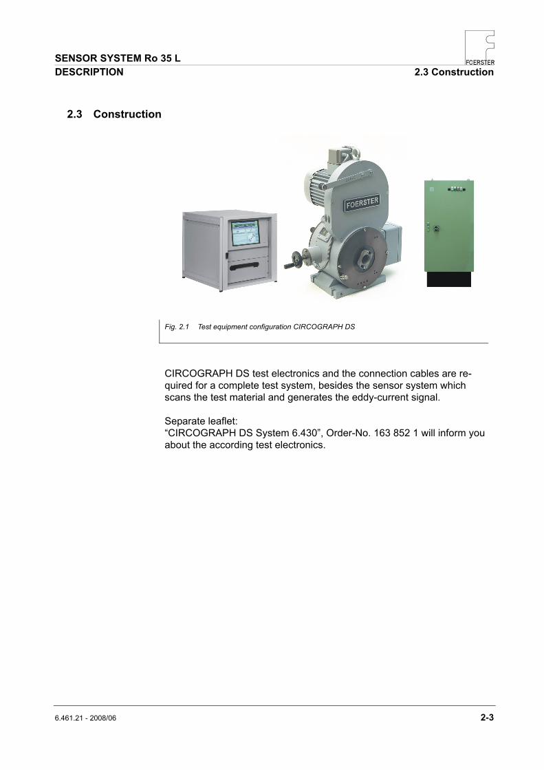
2.3 Construction
CIRCOGRAPH DS test electronics and the connection cables are re-quired for a complete test system, besides the sensor system which scans the test material and generates the eddy-current signal.
Separate leaflet: “CIRCOGRAPH DS System 6.430”, Order-No. 163 852 1 will inform you about the according test electronics.
Fig. 2.1 Test equipment configuration CIRCOGRAPH DS

SENSOR SYSTEM Ro 35 L 2.3 Construction DESCRIPTION
2-4 6.461.21 - 2008/06
Nozzle Holder Outside Nozzle Outside Nozzle Inside Nozzle Holder Inside
Fig. 2.2 CIRCOGRAPH sensor system Ro 35 L
Roller guide left ∅ 4.5 – 35
6.461.01-5001
Roller guide right ∅ 4.5 – 35
6.461.01-5011
Throughput preferred direction
(both directions possible)

SENSOR SYSTEM Ro 35 L DESCRIPTION 2.3 Construction
6.461.21 - 2008/06 2-5
In order to withstand the rough conditions of use, the rotating head has been designed to be dust-protected, robust and reliable by means of complex constructional measures such as labyrinth seals and dirt deflec-tors.
The chamber surrounding the test zone serves the purpose of contact and burst protection as well as dust collection. This chamber is provided with a connection facility for a suction connector for an external extraction system (to be provided by customer).
The sensor system consists of the following compulsory components:
rotating head Ro 35 L
test heads, track width 2.5 and 5 mm
protective nozzles
The following options are available for adaptation to particular material conditions:
roller guides

SENSOR SYSTEM Ro 35 L 2.3 Construction DESCRIPTION
2-6 6.461.21 - 2008/06
2.3.1 Test Heads
The test heads are both the heart of the sensor system and its most criti-cal components.
They consist of an eddy-current probe with field, measuring and clear-ance windings which are installed in a precise mechanical holder and are connected by means of a highly flexible special cable with a connection plug.
Due to high centrifugal forces (acceleration up to 4,500 g!) and the rough environmental conditions at the testing location, the probes are protected by a ceramic armor, nevertheless replacement of probes is possible.
As already mentioned in the ‘Mode of operation’ section, there is a mathematical relationship between the number and track width of the test heads, the rotational speed and the test speed.
The following table shows these relationships and gives typical examples for a practical selection:
Maximum test speed [m/s]
Decreasing sensitivity to short
flaws
Track width BS [mm]
Test head type
0.75 1.5
2.5 6.461.21-2025
1.5 3.0
5.0 6.461.21-2050
n = 4,500 rpm n = 9,000 rpm
Tab. 2.1 Test head selection
Rotating disc with test heads
Probe Test head

SENSOR SYSTEM Ro 35 L DESCRIPTION 2.3 Construction
6.461.21 - 2008/06 2-7
2.3.2 Rotating Head Ro 35 L
The rotating head is the main component of the sensor system.
It consists of:
rotor transmitter drive housing rotating head electronics
The test direction can be selected as right or left (viewed in the throughput direction).
Rotor
The rotor consists of a hollow shaft, a rotor disc and the movable part of the transmitter.
The rotor is driven by the motor by means of a high-power profile flat belt. It is supported in the housing by two high-speed bearings.
The high-precision rotating disc for holding the test heads is fitted on the front side.
A pivot-mounted spiral disc with an actuating gear and automatic blocking facility is fitted in the rotating disc for precise and simultaneous test head diameter adjustment.
DANGER! Never run the rotating head without test heads!
Fig. 2.3 Rotating head Ro 35 L
Fig. 2.4 Rotating disc with test heads View through the opened adjust-ment side, housing flange and cover of rotating disc removed

SENSOR SYSTEM Ro 35 L 2.3 Construction DESCRIPTION
2-8 6.461.21 - 2008/06
Transmitter
Wear-resistant rotating transmitter in disc-type construction with a field transmitter, two measuring channels and a clearance channel.
Consisting of a rotor and stator, it transmits the field current for the rotat-ing probes from the stator to the rotor and, in the opposite direction, transmits the test signal to the test electronics for evaluation.
Rotating head electronics
The rotating head electronics amplifies the probe signals and the field cur-rent. It is installed in a robust box on the connection side of the bearing housing to permit ease of maintenance. The cable to the test electronics is connected using MIL plug connectors.
Fig. 2.5 Signal path

SENSOR SYSTEM Ro 35 L DESCRIPTION 2.3 Construction
6.461.21 - 2008/06 2-9
Drive
Indestructible 3-phase drive with a cage motor in conformance with stan-dards.
External motor control for power supply to the drive.
The following versions are available:
MOC E motor control
fixed rotational speed of 4,500 rpm at 50 Hz mains supply
reasonably priced version, recommended for test speeds at which a ro-tational speed of 4,5000 rpm is sufficient for gapless testing (cf. Test head selection table, page 2-6)
MOC S/SB motor control
rotational speed switchable 4,500 or 9,000 rpm, with or without electrical breaking
minimized bearing wear through adaptation of rotational speed to test speed
suitable for applications with changing test speeds
Both motor controls supply the required voltages and currents and contain the necessary switching and safety devices (contactors, motor protection switches, protective circuits).
The drive motor is connected directly using a Harting plug connector.

SENSOR SYSTEM Ro 35 L 2.3 Construction DESCRIPTION
2-10 6.461.21 - 2008/06
Diameter adjustment
Diameter adjustment is carried out manually with a hand wheel. The lin-ear scale is located on the rotor. The diameter can be adjusted with an accuracy of 0.1 mm.
Protective nozzles standard
The protective nozzles have a dual function:
They protect the test heads from damage, particularly during entry and exit of the test material, provided that the straightness conditions and the end properties are observed.
They limit the maximum eccentricity of the test material within the zone to be tested to a narrow dimension within which the clearance compensation can fully compensate the sensitivity fluctuations.
Protective nozzles are available in nominal sizes of 5.0 to 36 mm.
Fig. 2.6 Protective nozzles, main picture, test heads and nozzle holder with change nozzles
Nozzle Holder Outside Nozzle Nozzle Nozzle Holder Inside

SENSOR SYSTEM Ro 35 L DESCRIPTION 2.3 Construction
6.461.21 - 2008/06 2-11
Entry and exit nozzles must always be used in pairs with the same nomi-nal value.
Protective nozzles can be ordered from INSTITUT DR. FOERSTER or can be manufactured by the customer on the basis of drawings.
WARNING! Operation without protective nozzles is not permitted for damage and safety reasons.
Fig. 2.7 Protective nozzles, main picture with nominal size 5 to 36 mm, nozzle holder with change nozzles
Nozzle Holder Outside Nozzle Nozzle Nozzle Holder Inside

SENSOR SYSTEM Ro 35 L 2.3 Construction DESCRIPTION
2-12 6.461.21 - 2008/06
Roller guide
The roller guides have two advantages:
In set-up mode, a calibration piece with reference flaws can be held cen-trically outside the testing line and the test electronics can be adjusted simply, since the rotating probes periodically scan the test flaw and dis-play the signal quasi-statically.
In testing mode, the roller guides improve centricity, especially for smaller dimensions, and damp vibrations. They are always required if the drivers for material transport cannot be set up directly in front of and behind the sensor system.
Fig. 2.8 Ro 35 L with roller guide

SENSOR SYSTEM Ro 35 L DESCRIPTION 2.4 Technical Data
6.461.21 - 2008/06 2-13
2.4 Technical Data
Ro 35 L
Diameter range test material 2 or 4 test heads
continuously adjustable 5 to 35 mm
Rotational speed MOC E motor control MOC S/SB motor control
4,500 rpm 4,500 or 9,000 rpm
Deceleration times from without braking with braking
9,000 rpm approx. 360 sec approx. 120 sec
Type of test without physical contact
Test heads (TH) two TH offset by 180° or four TH offset by 90° adjustable according to a scale, with one probe each
Probe track width of TH 5 mm, 2.5 mm
vmax for 2 TH 4 TH Test speed for gapless testing (5 mm track width) rpm = 4,500
rpm = 9,000 0.75 m/s 1.5 m/s
1.5 m/s 3.0 m/s
Dimensions see dimension sheet
Weight approximately 70 kg
Drive Three-phase motor
no = 1,425 rpm P = 1.4 kW no = 2,850 rpm P = 1.8 kW
Power supply 3x400 V three-phase, different supply voltage adapted via an isolating transformer
Useful bearing life (depending on operating conditions)
operating hours approx. 7,000 h approx. 5,000 h
typically at 4,500 rpm 9,000 rpm
Roller guide (option) Ø 4.5 to 35 mm
Weight approx. 3.8 kg
Dimensions see dimension sheet

SENSOR SYSTEM Ro 35 L 2.5 Dimension sheet DESCRIPTION
2-14 6.461.21 - 2008/06
2.5 Dimension sheet
Fig. 2.9 Dimension sheet 1

SENSOR SYSTEM Ro 35 L DESCRIPTION 2.5 Dimension sheet
6.461.21 - 2008/06 2-15
Fig. 2.10 Dimension sheet 2

SENSOR SYSTEM Ro 35 L 2.6 Environmental conditions DESCRIPTION
2-16 6.461.21 - 2008/06
2.6 Environmental conditions
Operation
Temperature range sensor rotating system
+5° C to +80° C +5° C to +45° C
Relative humidity sensor rotating system
95 %, casually condensation permissible 85 %, condensation not permissible
Degree of protection sensor rotating system
EN (60 529) IP 65 IP 43
Storage and transport
Storage, transport and handling may be carried out in original packaging only. The packages must be protected from moisture.
Observe instructions on the packaging (e.g. fragile, store in a dry place, this way up, etc.)
Storage conditions
storage in unopened original packaging
in closed rooms
temperature range -20° C to +70° C
max. relative humidity 95 %, condensation not permissible
maximum storage duration approx. 12 months (extension possible after intermediate check by FOERSTER employee)
Emissions
The A-weighted sound pressure level at intervals of 1 m from the ma-chine's surface and at 1.60 m height is for maximum rotational speed 9,000 rpm on exit side
outside testing line: without material 91 dB(A), with material 88 dB(A)
Inside the testing line the values are smaller (dependent on the installa-tion). On the operator's workstations the values are smaller in the case of greater distances.

SENSOR SYSTEM Ro 35 L DESCRIPTION 2.7 Standard Components
6.461.21 - 2008/06 2-17
2.7 Standard Components
Designation Drawing-No. Order-No Rotating head Ro 35 L 6.461.21-1002 1665766 Test cable DS 10M, CIRCOGRAPH-DS 6.460.01-9921 1650785 Motor cable 10M 6.460.01-9931 1638343 Grounding cable 10M 1.175-0061 1554034 Test head, BS=2.5 6.461.21-2025 1660969 Test head, BS=5 6.461.21-2050 1660985 Nozzle holder inside 6.461.21-1001-20 1612034 Nozzle holder outside 6.461.21-1001-25 1612751 Nozzle, nominal size 5-36 6.461.01-3211 1613251 Set of tools Ro 35P 6.461.01-1001-30 1659588 Roller guide, left, nominal size 4.5-35 6.461.01-5001 1611720 Roller guide, right, nominal size 4.5-35 6.461.01-5011 1611780 Motor control, MOC E 6.430.01-3010 1638254 Motor control, MOC S 6.430.01-3030 1638270 Motor control, MOC SB 6.430.01-3040 1638289 Operating Instructions, German, Sensor system Ro 35 L 6.461.21 UA06/DE 1664786 Operating Instructions English, Sensor system Ro 35 L 6.461.21 UA06/EN 1664794

SENSOR SYSTEM Ro 35 L 2.7 Standard Components DESCRIPTION
2-18 6.461.21 - 2008/06
Notes:

SENSOR SYSTEM Ro 35 L INSTALLATION 3.1 Setup and Connection
6.461.21 - 2008/06 3-1
3 INSTALLATION
3.1 Setup and Connection
NOTE! The sensor system must be mounted on a horizontally shiftable lifting table in order to be able to change the dimensions or to carry out ser-vice work outside of the testing line.
Requirements of the lifting table: It must be designed accordingly for the weight and function of the sen-sor system
adequate load-bearing capacity low-vibration design able to be fixed in test position With precise vertical adjustment facility Able to be withdrawn from the test position to service position and able to be removed reproducibly back; withdrawing travel at least 700 mm The mounting surface for the sensor system must be completely hori-zontal at every elevation (this must be checked with a precision spirit level) Cable skid for protecting the cables against damage when traversing the lifting table
The two horizontal end positions of the lifting table (service position/test position) should each be monitored with a limit switch. The limit switches must be gated with the roller conveyor control system in such a way that the roller conveyor can be switched on only if the table is fixed on one of the end positions. In addition, it must be ensured that the table can be moved out and in or vertically adjusted only if the roller conveyor is switched off and no test material inside.
Fig. 3.1 Aligning the sensor system on the lifting table
Ground mandrel, checked for concentricity Ø = nominal dimension entry and exit nozzle
Adjust at the entry and exit sides. The en-try and exit roller conveyors must be pre-cisely aligned. After precise adjustment, bolt the rotation head to the lifting table, recheck alignment and pin the rotating head foot.
Nozzle holder outside Nozzle holder inside
Roller conveyor Roller conveyor
Lifting table
Rotating head

SENSOR SYSTEM Ro 35 L 3.1 Setup and Connection INSTALLATION
3-2 6.461.21 - 2008/06
Electrical connections
Connection motor cable
Connection testing cable
NOTE! In case of noise signals at the rotating head change the special washer Nylite Siegel D=6. For job instructions see Service Manual. Protective conductor connection (PE) according to EN 61010 (VDE 0411) Connect the protective conductor terminal of the electronic cabinet and the other system components, e. g. control cabinets, motor control, ro-tating heads with the next main protective conductor terminal 16 mm2. A green/yellow lead with 16 mm2 Cu is to be used for that.
Fig. 3.3 Connection 2-channel rotating head to CIRCOGRAPH DS
Fig. 3.2 Rotating head, connections
Motor control
Test Electronics
Power line
Testing cable 10 m
6.460.01-9921
Light barrier
Motor cable 10 m 6.460.01-9931
Remote cable Remote (option)
Cooling air

SENSOR SYSTEM Ro 35 L OPERATION 4.1 Dimension change
6.461.21 - 2008/06 4-1
4 OPERATION
4.1 Dimension change
The following steps must be carried out during conversion:
I Set test head to new nominal value of test material
II Insert suitable protective nozzles
III Set roller guides to test diameter
IV Centre sensor system in the testing line
Preparation
Select protective nozzles for new test piece measurement. Prepare tools for dimension change.
WARNING! Risk of injury! Do not intervene manually in the sensor system when the rotating unit is running! Switch off drive before carrying out any work! Wait for machine standstill! Deceleration times from max. rotational speed 9,000 rpm: approx. 120 seconds (with manual braking).
Dimension change procedure
Switch off sensor system drive. Move sensor system out of the testing line. Open both roller guides. Remove entry and exit nozzle. Clean nozzle mount carefully. Adjust test heads to the new nominal diameter of the protective nozzles. Install nozzles. Check setting (observe smooth running of rotor). Move rotating head into testing line. Insert test material.

SENSOR SYSTEM Ro 35 L 4.2 Selection and installation of the protective nozzles OPERATION
4-2 6.461.21 - 2008/06
4.2 Selection and installation of the protective nozzles
4.2.1 Selection of the protective nozzles
Function of the protective nozzles
guarantee protection from damage during entry, even for test pieces with larger diameters, impermissible curvatures or deformed fronts or ends
in addition during operation without roller guides: guide the test material with low eccentricity
On the basis of empirical values, the relationship between test material and protective nozzle diameter for obtaining good test results has been set out as follows:
D mm DD mm 5 – 8 D + 0.1
> 8 – 15 D + 0.5 > 15 – 35 D + 1.0
The FOERSTER standard protective nozzle range is based on the grad-ing recommendation above.
The protective nozzles can be selected more precisely depending on the test diameter if the quality of guidance is sufficiently precise. This can im-prove the test results.
Tab. 4.1 Target nozzle grading for D = nominal diameter of test material DD = nominal size of protective nozzles

SENSORSY STEM Ro 35 L OPERATION 4.2 Selection and installation of the protective nozzles
6.461.21 - 2008/06 4-3
Standard nozzle
Important! Do not slide the test material in and out without nozzle – risk of major damage.
Operate only with protective nozzles! Nozzle Outside Drawing No. Nominal dimension mm Step mm
Standard 6.461.01-3211 5.0 to 36.0 See table 4.1
Fig. 4.1 Protective nozzle, schematic guide, NM 5 to 36 mm, nozzle holder with change nozzles

SENSOR SYSTEM Ro 35 L 4.2 Selection and installation of the protective nozzles OPERATION
4-4 6.461.21 - 2008/06
4.2.2 Required tools
Tool Order-No Hexagon screwdriver, straight a/f 5 x 200 mm, T-handle
016 851 3
Hexagon screwdriver, straight a/f 4 mm, spherical head
012 013 8
Hexagon screwdriver, straight a/f 3 x 100 mm, T-handle
014 038 4
Hexagon screwdriver, straight a/f 5 x 100 mm, T-handle
014 002 3
Hook spanner 25 to 28 mm 030 532 4
Fixed/ring-spanner SW 10/10
014 040 6
Wrench 154 215 0
Adjusting pliers, shape B 030 189 2
Pin puller 137 215 7
Roll-up tool bag type 170 144 030 484 0

SENSORSY STEM Ro 35 L OPERATION 4.3 Adjusting nominal diameter
6.461.21 - 2008/06 4-5
4.3 Adjusting nominal diameter
4.3.1 Preparation
Select protective nozzles according to Chapter 4.2.
Switch off drive and wait for standstill.
Move test material out of the sensor system.
Move sensor system out of the testing line.
WARNING! For safety reasons, a safety switch interrupts the power supply of the drive as soon as the door of the drive cover is opened. Do not change the function of the safety switch under any circumstances!
Fig. 4.2 Adjustment side with rotor cover
Safety switch Cover lock Rotor cover

SENSOR SYSTEM Ro 35 L 4.3 Adjusting nominal diameter OPERATION
4-6 6.461.21 - 2008/06
4.3.2 Removing nozzle holder
Adjustment side
Open roller guides with hand wheel until the nozzle holder is accessible.
Undo fastening of outside nozzle holder.
Turn outside nozzle holder ant-clockwise.
Remove outside nozzle holder.
Fig. 4.3 Adjustment side, nozzle holder in removal position
Fig. 4.4 Adjustment side, nozzle holder removed
Remove nozzle holder 2 hexagon sockets 5 mm

SENSORSY STEM Ro 35 L OPERATION 4.3 Adjusting nominal diameter
6.461.21 - 2008/06 4-7
Drive side
Open roller guides with hand wheel until nozzle holder is accessible.
Undo fastening of inside nozzle holder.
Turn inside nozzle holder anti-clockwise.
Remove inside nozzle holder.
Fig. 4.5 Drive side, nozzle holder in removal position
Fig. 4.6 Drive side, nozzle holder removed
Remove inside nozzle holder 2 hexagon sockets 5 mm

SENSOR SYSTEM Ro 35 L 4.3 Adjusting nominal diameter OPERATION
4-8 6.461.21 - 2008/06
4.3.3 Changing nozzles
Unscrew the nozzles from the nozzle holder using two hook spanners.
CAUTION! If the nozzle holder is fixed in a vice, clamp on the surfaces only!
Screw in new protective nozzles.
Fix nozzles using hook spanners.
Check end position! Danger of collision with test head!
NOTE! Use only nozzle pairs with the same nominal diameter!
WARNING! Adjust the test heads to the nominal diameter of the protective nozzles before inserting the nozzle holders! Inserting the nozzle holders into a test head arrangement that is too narrow can cause damage to the test heads and/or nozzles.
Fig. 4.7 Nozzle holders, nozzles and hook spanners
Outside nozzle holder Hook spanner Outside protective nozzle Inside protective nozzle Inside nozzle holder

SENSORSY STEM Ro 35 L OPERATION 4.3 Adjusting nominal diameter
6.461.21 - 2008/06 4-9
4.3.4 Adjusting probe clearance
The test heads are adjusted to the nominal diameter (clear opening) of the protective nozzles by a hand wheel.
A standstill detection facility installed in the adjusting device prevents ac-tuation until the rotating head has come to a standstill.
The adjustment scale is calibrated in such a matter that a safety distance of 0.2 mm is maintained between the protective nozzle and test head when adjusting to the nominal diameter over the entire adjustment range.
Fig. 4.8 Definition of the settings on the test head D test piece diameter DD nominal diameter A safety distance between protective nozzles and test head
Fig. 4.9 Scale and adjusting device
SENSOR SYSTEM Ro 35 L 4.3 Adjusting nominal diameter OPERATION
4-10 6.461.21 - 2008/06
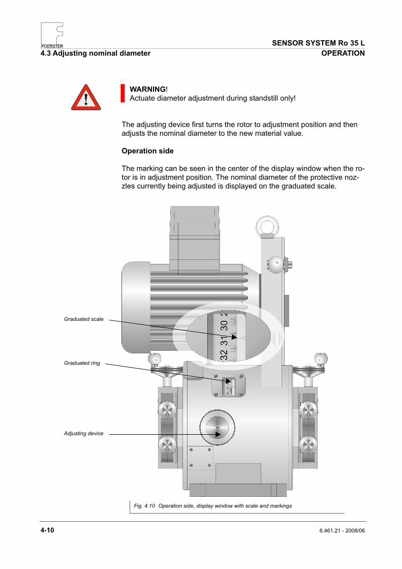
WARNING! Actuate diameter adjustment during standstill only!
The adjusting device first turns the rotor to adjustment position and then adjusts the nominal diameter to the new material value.
Operation side
The marking can be seen in the center of the display window when the ro-tor is in adjustment position. The nominal diameter of the protective noz-zles currently being adjusted is displayed on the graduated scale.
Fig. 4.10 Operation side, display window with scale and markings
Graduated scale Graduated ring Adjusting device

SENSORSY STEM Ro 35 L OPERATION 4.3 Adjusting nominal diameter
6.461.21 - 2008/06 4-11
Alternative: end face
Open rotor cover. To do this, pull the ball handle and swivel out the locking plate.
NOTE! The setting ring for nominal dimension adjustment is self-locking.
Fig. 4.11 Nozzle holders, nozzles and hook spanners
Fig. 4.12 Adjustment side, tools inserted for nominal dimension adjustment
Hand wheel Cover lock Cover

SENSOR SYSTEM Ro 35 L 4.3 Adjusting nominal diameter OPERATION
4-12 6.461.21 - 2008/06
Changing adjustment value
NOTE! Brake the rotating head to a standstill with the hand brake before adjustment!
Push in the hand wheel and turn until the actually valid diameter has reached the adjustment position.
Push in the hand wheel completely in adjustment position and set new nominal diameter.
Pull the hand wheel back into idle position.
Fig. 4.13 Idle position
Fig. 4.14 Finding adjustment position
Fig. 4.15 Adjustment position
SENSORSY STEM Ro 35 L OPERATION 4.4 Rotational speed preselection
6.461.21 - 2008/06 4-13
4.3.5 Adjusting roller guide
Open roller guide in accordance with material diameter.
Insert test material.
Adjust roller guide so that the rollers just touch the test material.
NOTE! The test piece must run centrically through the sensor system, if nec-essary adjust the table to the height of the test axis and lock.
4.4 Rotational speed preselection
The following rotational speeds are available depending on the type of motor control:
MOC E motor control
fixed rotational speed of 4,500 rpm 50 Hz mains supply
MOC S/SB motor control
Rotational speed switchable 4,500 or 9,000 rpm, with or without electrical brake system
Both motor controls supply the required voltages and currents and contain the necessary switching and safety devices (contactors, motor protection switches, protective circuits).

SENSOR SYSTEM Ro 35 L 4.5 Switching on motor OPERATION
4-14 6.461.21 - 2008/06
4.5 Switching on motor
NOTE! Check the diameter and height settings of the sensor system before switching on.
The operating elements used to switch on the rotating head drive are lo-cated on the motor control. The motor control is installed in a separate housing.
Acceleration times: approx. 4 sec (4,500) rpm approx. 10 sec (9,000) rpm
Deceleration times without braking: approx. 210 sec (4,500) rpm approx. 360 sec (9,000) rpm
The braking time until standstill can be reduced to a few seconds by actu-ating the hand brake.
The rotating head must run quietly and without loud noises when no test material is present.
Whistling noises when starting or braking indicate that the belt needs to be retensioned.
NOTE! Switch off the drive immediately if grinding noises are heard. Possible causes: Incorrect test head replacement parts inserted Incorrect nozzles inserted Nozzle or holders not securely fitted Nozzle not fitted in end position

SENSORSY STEM Ro 35 L OPERATION 4.6 Application drawing line
6.461.21 - 2008/06 4-15
4.6 Application drawing line
Dimension change - definitions
Position of the test heads, testing without physical contact and with excel-lent centering of the test material. Normal setting for correct diameter setting and correct nominal diameter of protective nozzle; A < APK. Test head behind the protective nozzle.
NOTE! The test heads have to be adjusted according to the nominal diameter DD of the nozzles over the whole diameter range.
Auxiliary nozzle for installation without straightening roller device
Fig. 4.16 D Test piece nominal diameter APK Test head clearance DD Protective nozzle nominal inside diameter A Distance nozzle - material
Nozzle Holder Outside
Nozzle Outside Nozzle Inside Nozzle Holder Inside Auxiliary nozzle (option)
Auxiliary nozzle (option)
Nozzle Holder Outside
Nozzle Outside Nozzle Inside Nozzle Holder Inside

SENSOR SYSTEM Ro 35 L 4.6 Application drawing line OPERATION
4-16 6.461.21 - 2008/06
Example:
Test piece Ø Nominal Ø nozzle Scale value 7 mm 7.5 7.5
12 mm 13.0 13.0 20 mm 21.5 21.5 30 mm 32.0 32.0 34 mm 36.0 36.0
Selecting and fitting the protective nozzles
WARNING! Do not slide the test material in or out without nozzles. This involves the risk of major damages! Never operate the system without protective nozzles installed!
Function
Protection of the test heads against unacceptable test material condi-tions. In particular, during entry and exit of drawing point or deformed nose or tail.
Limitation of the deviation of the test material with respect to the rotat-ing head axis.
Guidance of test head when using floating table
Drawing No. Nominal size Nominal size = Test piece +
Auxiliary nozzles Entry nozzles Exit nozzles mm inch mm inch 6.452.01-5901-0050 6.461.21-3215 6.461.21-3216 5.0 0.0787
etc. up to 6.452.01-5901-0079 6.461.21-3215 6.461.21-3216 7.9 0.3104
0.5 0.0196
6.452.01-5901-0080 6.461.21-3215 6.461.21-3216 8 0.3149 etc. up to
6.452.01-5901-0150 6.461.21-3215 6.461.21-3216 15 0.5905
7 0.0393
6.452.01-5901-0151 6.461.21-3215 6.461.21-3216 15.1 0.5934 etc. up to
6.452.01-5901-0250 6.461.21-3215 6.461.21-3216 25 0.9825
1.5 0.0590
6.452.01-5901-0251 6.461.21-3215 6.461.21-3216 25.1 0.9864 etc. up to
6.452.01-5901-0360 6.461.21-3215 6.461.21-3216 36 1.4173
2 0.0786
Tab. 4.2 Standard protective guide series 5.0 to 36.0 mm application drawing line

SENSOR SYSTEM Ro 35 L MAINTENANCE 5.1 Maintenance schedule
6.461.21 - 2008/06 5-1
5 MAINTENANCE
5.1 Maintenance schedule
WARNING! Risk of injury! Always switch off the drive and wait for the machine to stop before per-forming work of any kind! Do not touch or tamper with the sensor system, with the rotating unit operating! Deceleration times: without braking approx. 6 minutes with braking approx. 120 seconds (Values are valid for maximum rotational speed 9,000 rpm)
Important!
Parts which are worn or damaged must be replaced immediately. when changing
dimensions each shift each week each month
Roller guide clean, check track rollers for wear and damage
oil joints, oil spindle, oil hinges
Nozzles Remove, check thoroughly and visually for damage
clean, check for wear and damage
Rotating parts clean clean, check for wear and damage
Testing heads clean, check for wear and damage
clean, check for wear and damage
Belt check tension check for wear and damage
Synchronization light barrier (separated from rotating head) clean
Tab. 5.1 Maintenance schedule

SENSOR SYSTEM Ro 35 L 5.2 Cleaning MAINTENANCE
5-2 6.461.21 - 2008/06
5.2 Cleaning
WARNING! Do not use solvent cleaner, petrol or alcohol! Use commercially available cleaning agents. Observe the instructions for use from the respective cleaning agent manufacturer.
Make sure the areas around the rotating parts are clean! Remove abrasion and dirt with an industrial vacuum cleaner. Clean rotating disc and test heads. Clean test piece sensor (external) with a soft cloth. Lightly oil bright metallic parts after cleaning. Open housing cover to clean inner chamber. Do not blow compressed air into open chamber!
Fig. 5.1 Cleaning chamber

SENSORSY STEM Ro 35 L MAINTENANCE 5.3 Removing and installing test heads
6.461.21 - 2008/06 5-3
5.3 Removing and installing test heads
5.3.1 Removing test heads
NOTE! Make sure the plug contacts are clean! You must not open the lock nut and locking screw.
Swivel cover outwards or remove. Set test heads to maximum diameter. Remove lid on front side: Undo five M6x10 DIN 912 hexagon socket screws. Remove lid.
Fig. 5.2 Removing lid on front side lock nut and locking screw
M6x10 DIN 912

SENSOR SYSTEM Ro 35 L 5.3 Removing and installing test heads MAINTENANCE
5-4 6.461.21 - 2008/06
Remove ring:
WARNING! The ring is spring-loaded and will get loose as soon as the screws are pulled off!
Undo four M6x10 DIN 912 hexagon socket screws (1).
Remove ring (2).
NOTE! The probe levers are now freely movable.
Fig. 5.2 Removing ring
(1)
(2)
M6x10 DIN 912

SENSORSY STEM Ro 35 L MAINTENANCE 5.3 Removing and installing test heads
6.461.21 - 2008/06 5-5
Take out test levers:
Undo the plug connection of the test head cable.
NOTE! The screws are undetachable!
Pull the test head outwards in axial direction.
Clean pivot pin and test lever bearing (roller bearing), grease lightly if necessary.
5.3.2
Fig. 5.3 Removing test levers

SENSOR SYSTEM Ro 35 L 5.3 Removing and installing test heads MAINTENANCE
5-6 6.461.21 - 2008/06
Installing test heads
CAUTION! Use test heads as a set with the same specifications. The type number is found on the side of the test heads.
Clean all parts, especially the contact surfaces.
DANGER! Risk of injury! Balancing of the rotating head only with ring and test lever removed!
The test levers are fixed by spring tension in the OPEN position during standstill of the rotor.
At the minimum rotating speed the levers tilt to the preadjusted testing diameter.
Lid Ring Test levers
Fig. 5.4 Sequence of components
Fig. 5.5 Testing position Fig. 5.6 Position OPEN

SENSORSY STEM Ro 35 L MAINTENANCE 5.3 Removing and installing test heads
6.461.21 - 2008/06 5-7
Push the test levers in the shown order onto the pivot pins and join to the adjusting lever.
Insert the plug connection of the test head cable; lock fastening screws.
Insert ring 15° counterclockwise.
Fig. 5.7 Fig. 5.8
Fig. 5.9 Fig. 5.10
Push Join
Fastening screws
Ring
Fig. 5.11 Fig. 5.12
SENSOR SYSTEM Ro 35 L 5.4 List of parts subject to wear MAINTENANCE
5-8 6.461.21 - 2008/06
Rotate ring to the end position and secure with four hexagon socket screws M6x10 DIN 912, while checking the mobility of test levers.
Fit lid (pay attention to position of pin) and secure with five hexagon socket screws M6x10 DIN 912.
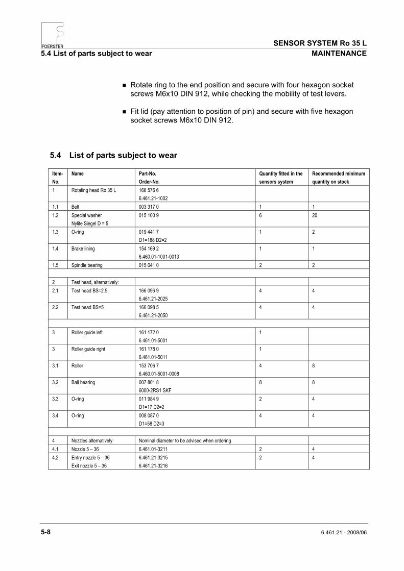
5.4 List of parts subject to wear
Item-No.
Name Part-No. Order-No.
Quantity fitted in the sensors system
Recommended minimum quantity on stock
1 Rotating head Ro 35 L 166 576 6 6.461.21-1002
1.1 Belt 003 317 0 1 1 1.2 Special washer
Nylite Siegel D = 5 015 100 9 6 20
1.3 O-ring 019 441 7 D1=188 D2=2
1 2
1.4 Brake lining 154 169 2 6.460.01-1001-0013
1 1
1.5 Spindle bearing 015 041 0 2 2 2 Test head, alternatively: 2.1 Test head BS=2.5 166 096 9
6.461.21-2025 4 4
2.2 Test head BS=5 166 098 5 6.461.21-2050
4 4
3 Roller guide left 161 172 0
6.461.01-5001 1
3 Roller guide right 161 178 0 6.461.01-5011
1
3.1 Roller 153 706 7 6.460.01-5001-0008
4 8
3.2 Ball bearing 007 801 8 6000-2RS1 SKF
8 8
3.3 O-ring 011 984 9 D1=17 D2=2
2 4
3.4 O-ring 008 087 0 D1=58 D2=3
4 4
4 Nozzles alternatively: Nominal diameter to be advised when ordering 4.1 Nozzle 5 – 36 6.461.01-3211 2 4 4.2 Entry nozzle 5 – 36
Exit nozzle 5 – 36 6.461.21-3215 6.461.21-3216
2 4

Institut Dr. Foerster GmbH & Co. KG Division TS Semi-finished Product TestingIn Laisen 70 72766 REUTLINGEN GERMANY
Telephone:Fax: E-mail: Internet:
+49 7121 140-270 +49 7121 140-459 [email protected] www.foerstergroup.de
6.461.21
Order no.: UA06/EN 166 479 4
Edition: Author:
06/2008 Leibssle