cimon plc function block system library user manual
TRANSCRIPT

CIMON PLC FUNCTION BLOCK SYSTEM LIBRARY USER MANUAL
WWW.CIMON.COM
CIMON PLC Function Block
System Library User Manual
Version: 20150609
CIMON PLC FUNCTION BLOCK SYSTEM LIBRARY USER MANUAL
WWW.CIMON.COM
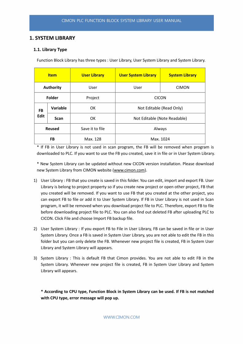
1. SYSTEM LIBRARY
1.1. Library Type
Function Block Library has three types : User Library, User System Library and System Library.
Item User Library User System Library System Library
Authority User User CIMON
Folder Project CICON
FB Edit
Variable OK Not Editable (Read Only)
Scan OK Not Editable (Note Readable)
Reused Save it to file Always
FB Max. 128 Max. 1024
* If FB in User Library is not used in scan program, the FB will be removed when program is
downloaded to PLC. If you want to use the FB you created, save it in file or in User System Library.
* New System Library can be updated without new CICON version installation. Please download
new System Library from CIMON website (www.cimon.com).
1) User Library : FB that you create is saved in this folder. You can edit, import and export FB. User
Library is belong to project property so if you create new project or open other project, FB that
you created will be removed. If you want to use FB that you created at the other project, you
can export FB to file or add it to User System Library. If FB in User Library is not used in Scan
program, it will be removed when you download project file to PLC. Therefore, export FB to file
before downloading project file to PLC. You can also find out deleted FB after uploading PLC to
CICON. Click File and choose Import FB backup file.
2) User System Library : If you export FB to File in User Library, FB can be saved in file or in User
System Library. Once a FB is saved in System User Library, you are not able to edit the FB in this
folder but you can only delete the FB. Whenever new project file is created, FB in System User
Library and System Library will appears.
3) System Library : This is default FB that Cimon provides. You are not able to edit FB in the
System Library. Whenever new project file is created, FB in System User Library and System
Library will appears.
* According to CPU type, Function Block in System Library can be used. If FB is not matched
with CPU type, error message will pop up.
CIMON PLC FUNCTION BLOCK SYSTEM LIBRARY USER MANUAL
WWW.CIMON.COM
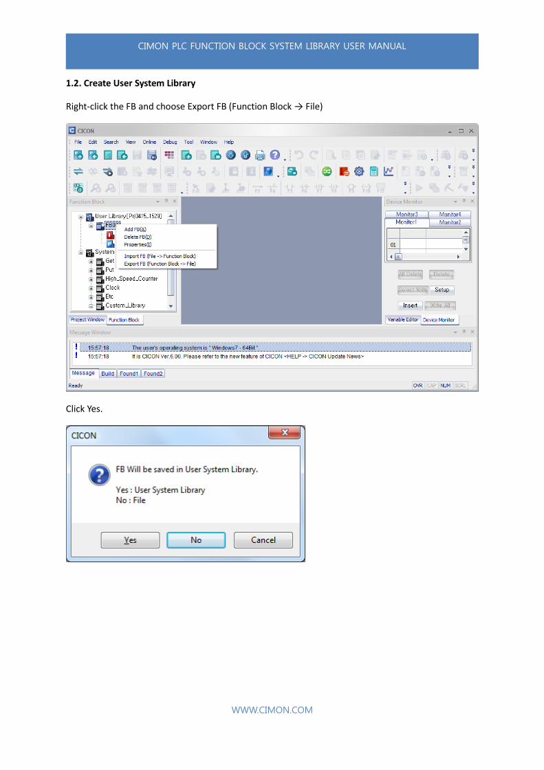
1.2. Create User System Library
Right-click the FB and choose Export FB (Function Block → File)
Click Yes.
CIMON PLC FUNCTION BLOCK SYSTEM LIBRARY USER MANUAL
WWW.CIMON.COM
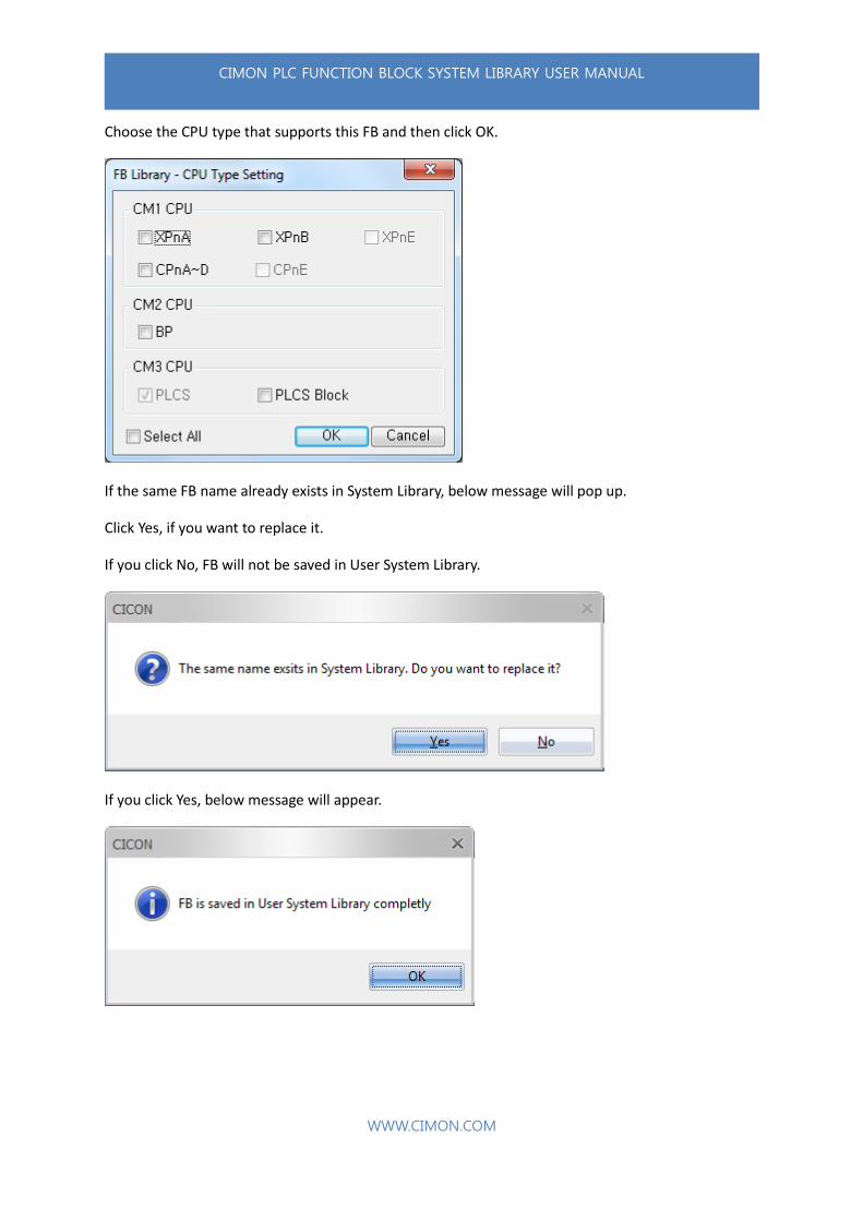
Choose the CPU type that supports this FB and then click OK.
If the same FB name already exists in System Library, below message will pop up.
Click Yes, if you want to replace it.
If you click No, FB will not be saved in User System Library.
If you click Yes, below message will appear.
CIMON PLC FUNCTION BLOCK SYSTEM LIBRARY USER MANUAL
WWW.CIMON.COM
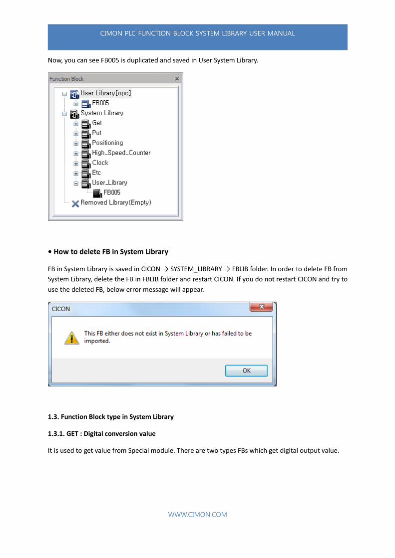
Now, you can see FB005 is duplicated and saved in User System Library.
• How to delete FB in System Library
FB in System Library is saved in CICON → SYSTEM_LIBRARY → FBLIB folder. In order to delete FB from
System Library, delete the FB in FBLIB folder and restart CICON. If you do not restart CICON and try to
use the deleted FB, below error message will appear.
1.3. Function Block type in System Library
1.3.1. GET : Digital conversion value
It is used to get value from Special module. There are two types FBs which get digital output value.

CIMON PLC FUNCTION BLOCK SYSTEM LIBRARY USER MANUAL
WWW.CIMON.COM
Example)
AD_M : It is used to get more than two digital values. D device is fixed to save this value. Type the
address on “ADDR” and type number of channels on “SIZE”. (If you want to get the values from
Channel 1~3, type 3. It will get a value from channel no.1 always.)
AD_S : It is used to get only one digital value. Output Device is fixed to save this value and can use
Word type device (D15, M70, K110 and etc.). Type channel number on “CH” (If you want to get a
value from Channel no.3, type 3)
1.3.1.1. AD_M
It has digital value from AD module and this digital value will be save in D device. It is used to get
more than one digital value if the FB name is finished with “_M”.
Variable Name I/O Type Device
BASE Input Word Write Base number 0~16
SLOT Input Word Write Slot number
CM1 : 0 ~ 11 / CM2 : 1 ~ 4 / CM3 : 1 ~ 11
ADDR Input Word Write D address. (Ex. D150 → Write 150)
SIZE Input Word Write number of Channel
(Ex. Ch.1→Write 1, Ch.1~3→Write 3)
OUTPUT Output Bit When it works, it will be turned ON
If you write wrong SLOT number or BASE number, CPU will have an error.
According to CPU type, D device address range will be different.
CIMON PLC FUNCTION BLOCK SYSTEM LIBRARY USER MANUAL
WWW.CIMON.COM
• System Library type
CM1_AD_M / CM1_AD16Ch_M / CM2_AD_M /
CM2_ADDA_AD_M / CM3_AD_M / CM3_ADDA_AD_M
• Buffer Memory Index
CM1 AD : 11 ~ 18 (Ch.1~8 : Digital Output value)
CM1 AD16Ch : 11 ~ 26 (Ch.1~16 : Measured value)
CM2 AD : 11 ~ 18 (Ch.1~8 : Digital Output value)
CM2 ADDA_AD : 7 ~ 8 (Ch.1~2 : Digital Output value)
CM3 AD : 0 ~ 3 (Ch.1~4 : Digital converted value)
CM3 ADDA_AD : 0 ~ 1 (Ch.1~2 : Digital converted value AD)
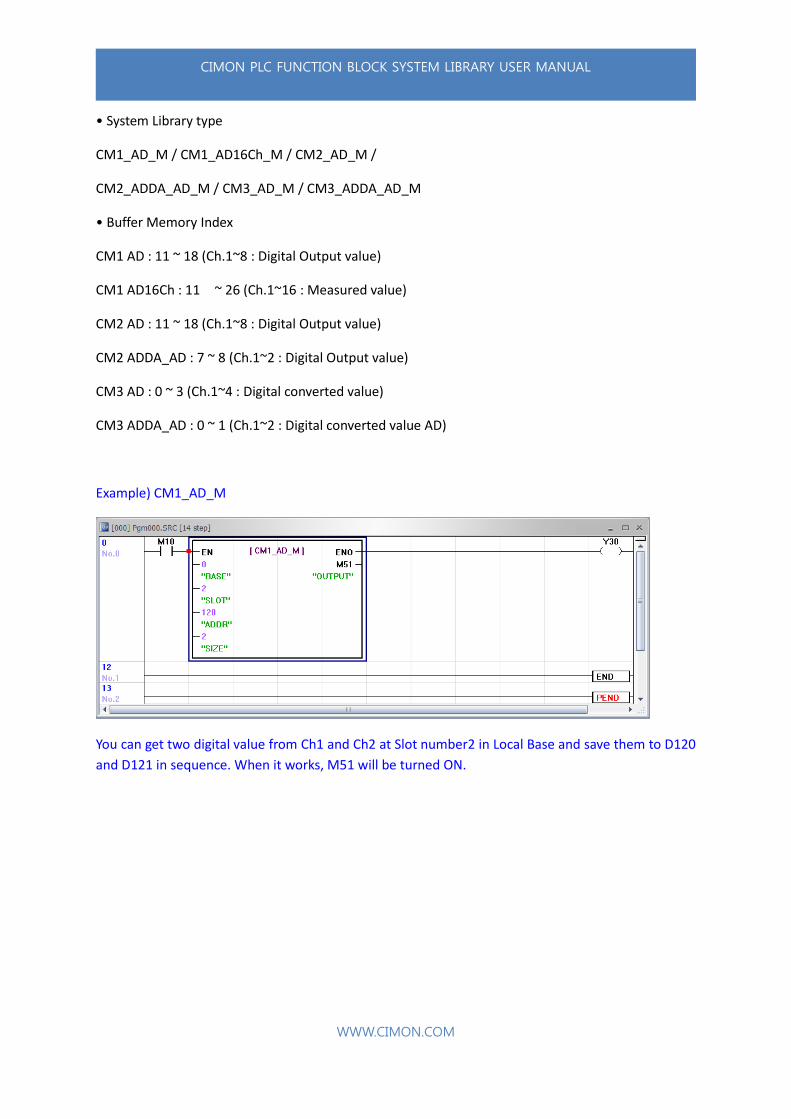
Example) CM1_AD_M
You can get two digital value from Ch1 and Ch2 at Slot number2 in Local Base and save them to D120
and D121 in sequence. When it works, M51 will be turned ON.
CIMON PLC FUNCTION BLOCK SYSTEM LIBRARY USER MANUAL
WWW.CIMON.COM
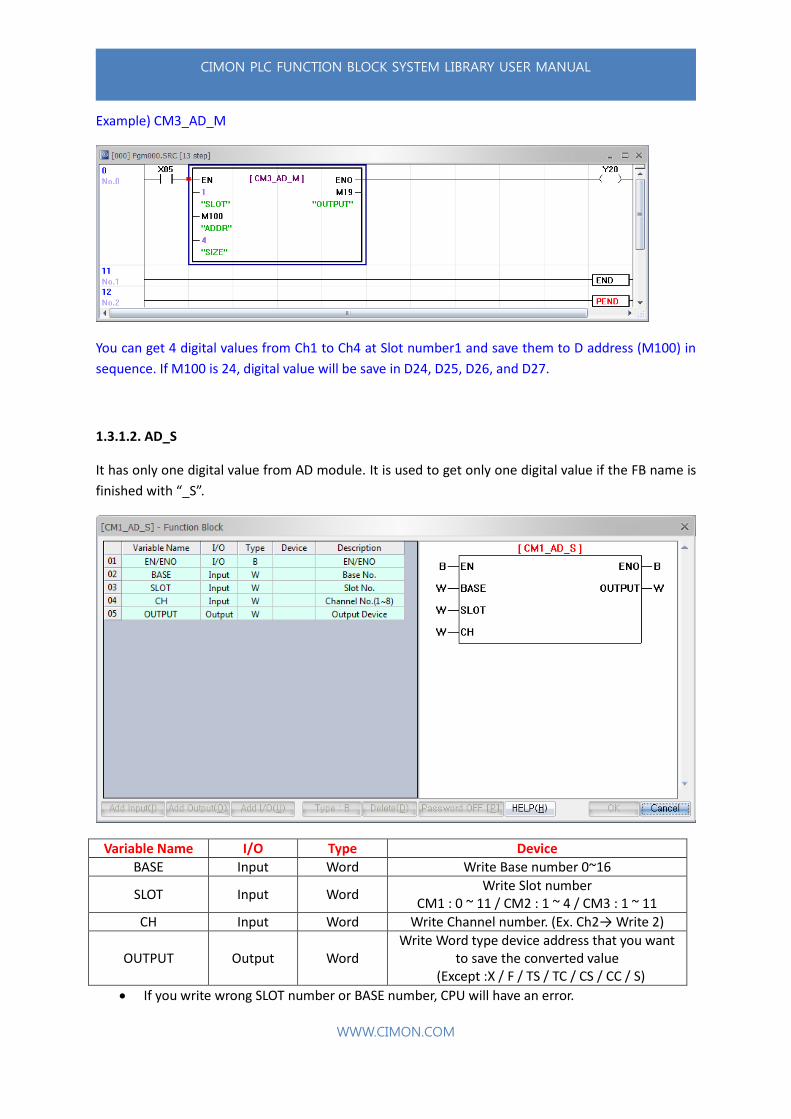
Example) CM3_AD_M
You can get 4 digital values from Ch1 to Ch4 at Slot number1 and save them to D address (M100) in
sequence. If M100 is 24, digital value will be save in D24, D25, D26, and D27.
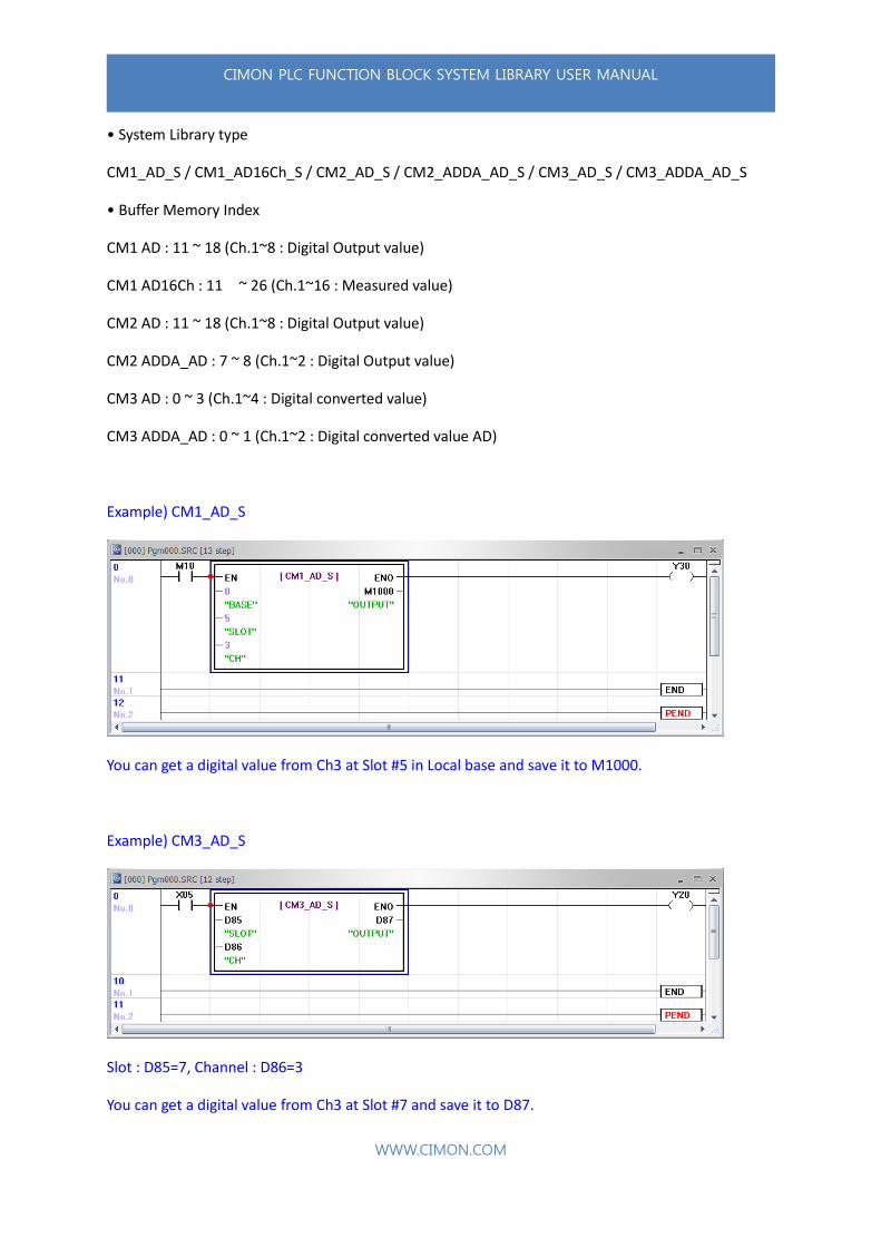
1.3.1.2. AD_S
It has only one digital value from AD module. It is used to get only one digital value if the FB name is
finished with “_S”.
Variable Name I/O Type Device
BASE Input Word Write Base number 0~16
SLOT Input Word Write Slot number
CM1 : 0 ~ 11 / CM2 : 1 ~ 4 / CM3 : 1 ~ 11
CH Input Word Write Channel number. (Ex. Ch2→ Write 2)
OUTPUT Output Word Write Word type device address that you want
to save the converted value (Except :X / F / TS / TC / CS / CC / S)
If you write wrong SLOT number or BASE number, CPU will have an error.
CIMON PLC FUNCTION BLOCK SYSTEM LIBRARY USER MANUAL
WWW.CIMON.COM
• System Library type
CM1_AD_S / CM1_AD16Ch_S / CM2_AD_S / CM2_ADDA_AD_S / CM3_AD_S / CM3_ADDA_AD_S
• Buffer Memory Index
CM1 AD : 11 ~ 18 (Ch.1~8 : Digital Output value)
CM1 AD16Ch : 11 ~ 26 (Ch.1~16 : Measured value)
CM2 AD : 11 ~ 18 (Ch.1~8 : Digital Output value)
CM2 ADDA_AD : 7 ~ 8 (Ch.1~2 : Digital Output value)
CM3 AD : 0 ~ 3 (Ch.1~4 : Digital converted value)
CM3 ADDA_AD : 0 ~ 1 (Ch.1~2 : Digital converted value AD)
Example) CM1_AD_S
You can get a digital value from Ch3 at Slot #5 in Local base and save it to M1000.
Example) CM3_AD_S
Slot : D85=7, Channel : D86=3
You can get a digital value from Ch3 at Slot #7 and save it to D87.

CIMON PLC FUNCTION BLOCK SYSTEM LIBRARY USER MANUAL
WWW.CIMON.COM
1.3.1.3. RTD_M
It has digital value from RTD module and this digital value will be save in D device. It is used to get
more than two digital values if the FB name is finished with “_M”.
Variable Name I/O Type Device
BASE Input Word Write Base number 0~16
SLOT Input Word Write Slot number
CM1 : 0 ~ 11 / CM2 : 1 ~ 4 / CM3 : 1 ~ 11
ADDR Input Word Write D address. (Ex. D150 → Write 150)
SIZE Input Word Write number of Channel
(Ex. Ch.1→Write 1, Ch.1~3→Write 3)
OUTPUT Output Bit Not Used
If you write wrong SLOT number or BASE number, CPU will have an error.
• System Library type
CM1_RTD_M / CM2_RTD_M / CM3_RTD_M
• Buffer Memory Index
CM1 RTD : 21 ~ 28 (Ch.1~8 : Digital converted value)
CM2 RTD : 21 ~ 28 (Ch.1~8 : Digital converted value)
CM3 RTD : 21 ~ 24 (Ch.1~4 : Digital converted value)
CIMON PLC FUNCTION BLOCK SYSTEM LIBRARY USER MANUAL
WWW.CIMON.COM
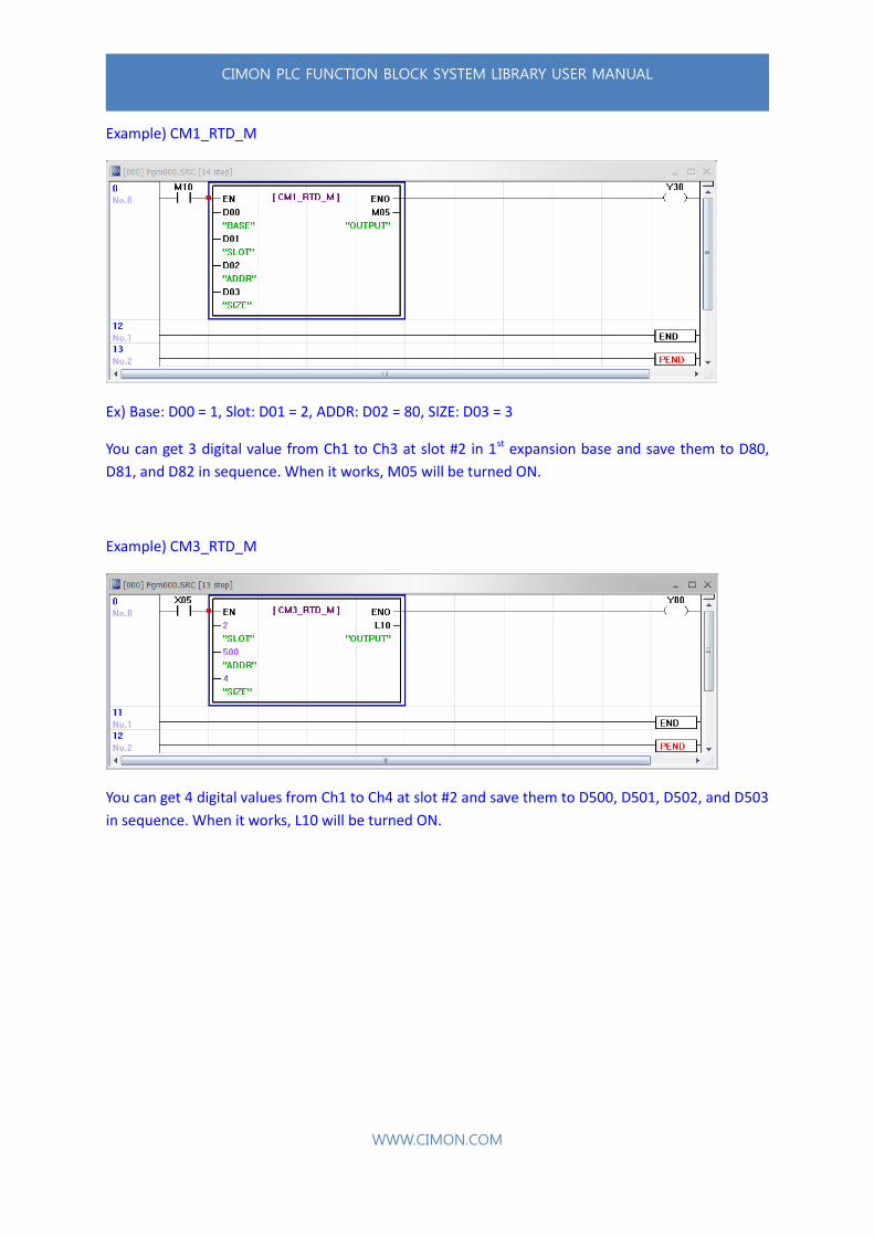
Example) CM1_RTD_M
Ex) Base: D00 = 1, Slot: D01 = 2, ADDR: D02 = 80, SIZE: D03 = 3
You can get 3 digital value from Ch1 to Ch3 at slot #2 in 1st expansion base and save them to D80,
D81, and D82 in sequence. When it works, M05 will be turned ON.
Example) CM3_RTD_M
You can get 4 digital values from Ch1 to Ch4 at slot #2 and save them to D500, D501, D502, and D503
in sequence. When it works, L10 will be turned ON.

CIMON PLC FUNCTION BLOCK SYSTEM LIBRARY USER MANUAL
WWW.CIMON.COM
1.3.1.4. RTD_S
It has only one digital value from RTD module. It is used to get only one digital value if the FB name is
finished with “_S”.
Variable Name I/O Type Device
BASE Input Word Write Base number 0~16
SLOT Input Word Write Slot number
CM1 : 0 ~ 11 / CM2 : 1 ~ 4 / CM3 : 1 ~ 11
CH Input Word Write Channel number. (Ex. Ch2→ Write 2)
OUTPUT Output Word Write Word type device address that you want
to save the converted value (Except :X / F / TS / TC / CS / CC / S)
If you write wrong SLOT number or BASE number, CPU will have an error.
• System Library type
CM1_RTD_S / CM2_RTD_S / CM3_RTD_S
• Buffer Memory Index
CM1 RTD : 21 ~ 28 (Ch.1~8 : Digital conversion value)
CM2 RTD : 21 ~ 28 (Ch.1~8 : Digital conversion value)
CM3 RTD : 21 ~ 24 (Ch.1~4 : Digital conversion value)
CIMON PLC FUNCTION BLOCK SYSTEM LIBRARY USER MANUAL
WWW.CIMON.COM
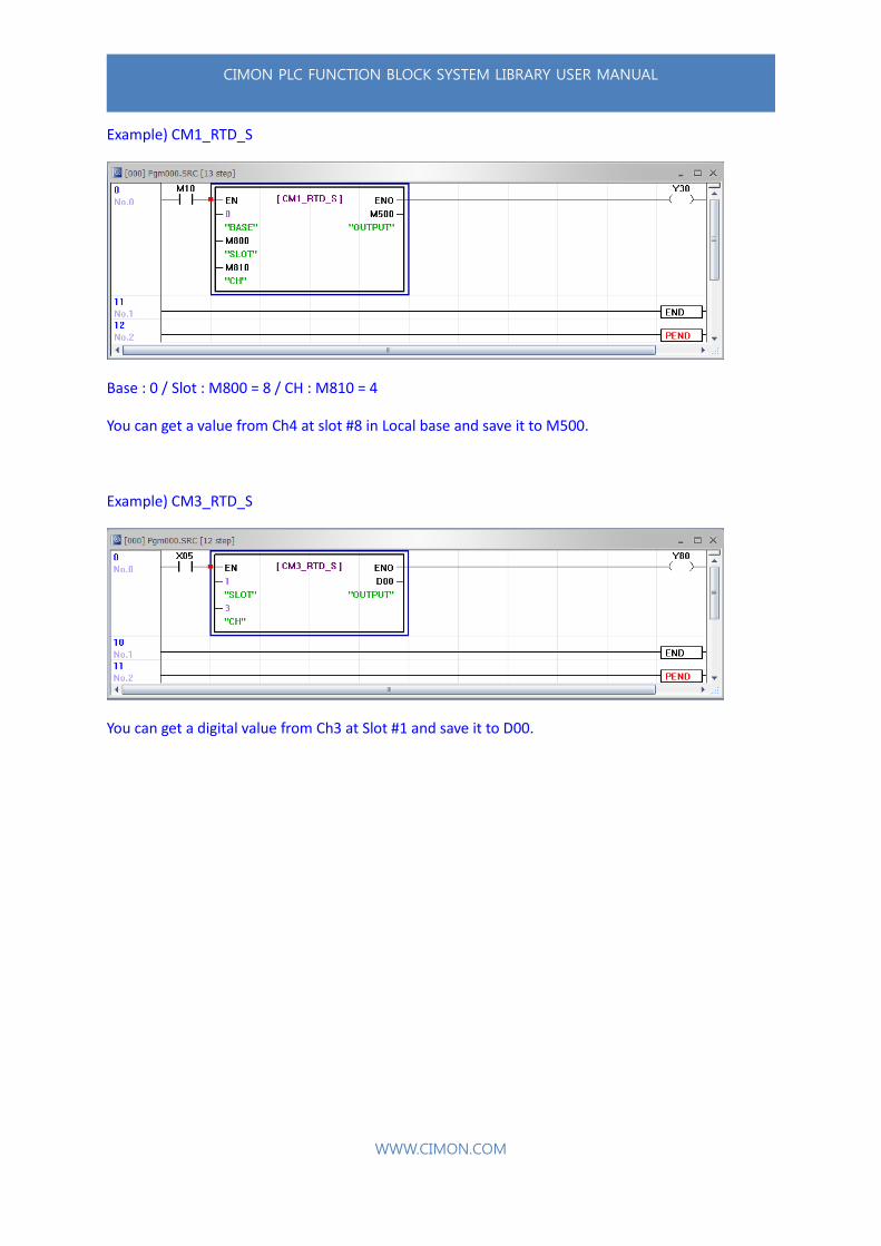
Example) CM1_RTD_S
Base : 0 / Slot : M800 = 8 / CH : M810 = 4
You can get a value from Ch4 at slot #8 in Local base and save it to M500.
Example) CM3_RTD_S
You can get a digital value from Ch3 at Slot #1 and save it to D00.

CIMON PLC FUNCTION BLOCK SYSTEM LIBRARY USER MANUAL
WWW.CIMON.COM
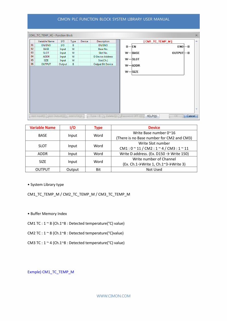
1.3.1.5. TC_M
It has digital value from TC module and this digital value will be save in D device. It is used to get
more than two digital values if the FB name is finished with “_M”.
Variable Name I/O Type Device
BASE Input Word Write Base number 0~16
SLOT Input Word Write Slot number
CM1 : 0 ~ 11 / CM2 : 1 ~ 4 / CM3 : 1 ~ 11
ADDR Input Word Write D address. (Ex. D150 → Write 150)
SIZE Input Word Write number of Channel
(Ex. Ch.1→Write 1, Ch.1~3→Write 3)
OUTPUT Output Bit When it works, it will be turned ON
If you write wrong SLOT number or BASE number, CPU will have an error.
• System Library type
CM1_TC_M / CM2_TC_M / CM3_TC_M
• Buffer Memory Index
CM1 TC : 21 ~ 28 (Ch.1~8 : Digital conversion value)
CM2 TC : 21 ~ 28 (Ch.1~8 : Digital conversion value)
CM3 TC : 21 ~ 24 (Ch.1~4 : Digital conversion value)
CIMON PLC FUNCTION BLOCK SYSTEM LIBRARY USER MANUAL
WWW.CIMON.COM
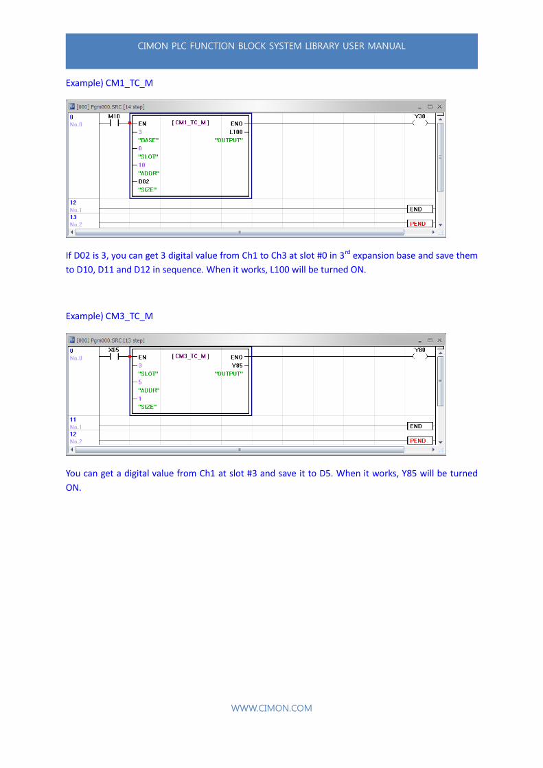
Example) CM1_TC_M
If D02 is 3, you can get 3 digital value from Ch1 to Ch3 at slot #0 in 3rd expansion base and save them
to D10, D11 and D12 in sequence. When it works, L100 will be turned ON.
Example) CM3_TC_M
You can get a digital value from Ch1 at slot #3 and save it to D5. When it works, Y85 will be turned
ON.
CIMON PLC FUNCTION BLOCK SYSTEM LIBRARY USER MANUAL
WWW.CIMON.COM
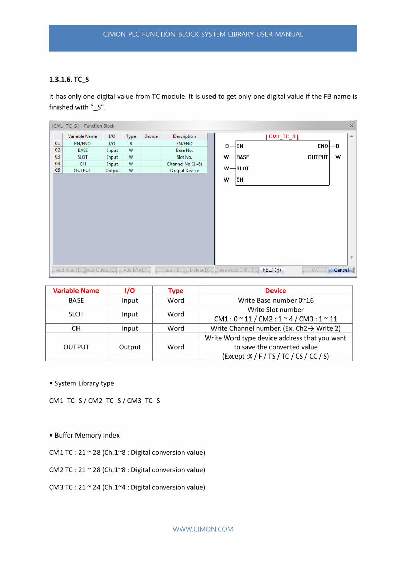
1.3.1.6. TC_S
It has only one digital value from TC module. It is used to get only one digital value if the FB name is
finished with “_S”.
Variable Name I/O Type Device
BASE Input Word Write Base number 0~16
SLOT Input Word Write Slot number
CM1 : 0 ~ 11 / CM2 : 1 ~ 4 / CM3 : 1 ~ 11
CH Input Word Write Channel number. (Ex. Ch2→ Write 2)
OUTPUT Output Word Write Word type device address that you want
to save the converted value (Except :X / F / TS / TC / CS / CC / S)
• System Library type
CM1_TC_S / CM2_TC_S / CM3_TC_S
• Buffer Memory Index
CM1 TC : 21 ~ 28 (Ch.1~8 : Digital conversion value)
CM2 TC : 21 ~ 28 (Ch.1~8 : Digital conversion value)
CM3 TC : 21 ~ 24 (Ch.1~4 : Digital conversion value)
CIMON PLC FUNCTION BLOCK SYSTEM LIBRARY USER MANUAL
WWW.CIMON.COM
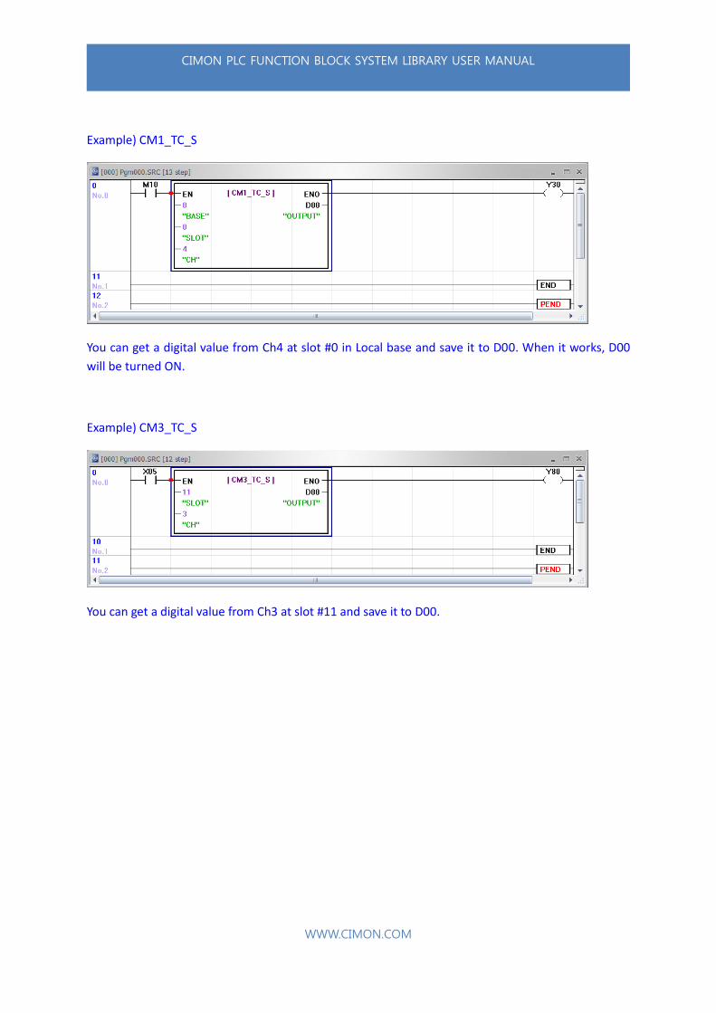
Example) CM1_TC_S
You can get a digital value from Ch4 at slot #0 in Local base and save it to D00. When it works, D00
will be turned ON.
Example) CM3_TC_S
You can get a digital value from Ch3 at slot #11 and save it to D00.
CIMON PLC FUNCTION BLOCK SYSTEM LIBRARY USER MANUAL
WWW.CIMON.COM
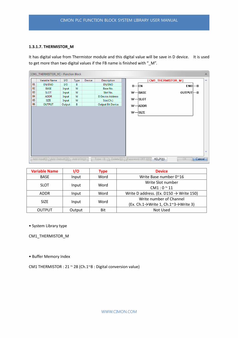
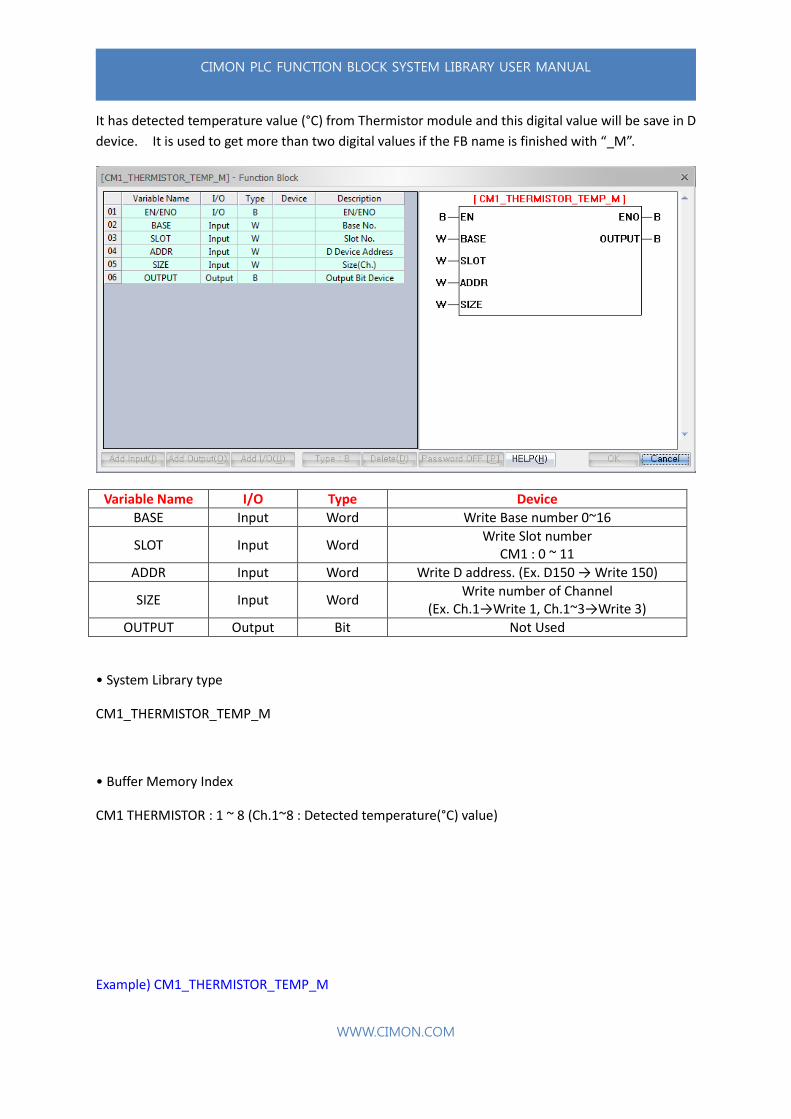
1.3.1.7. THERMISTOR_M
It has digital value from Thermistor module and this digital value will be save in D device. It is used
to get more than two digital values if the FB name is finished with “_M”.
Variable Name I/O Type Device
BASE Input Word Write Base number 0~16
SLOT Input Word Write Slot number
CM1 : 0 ~ 11
ADDR Input Word Write D address. (Ex. D150 → Write 150)
SIZE Input Word Write number of Channel
(Ex. Ch.1→Write 1, Ch.1~3→Write 3)
OUTPUT Output Bit Not Used
• System Library type
CM1_THERMISTOR_M
• Buffer Memory Index
CM1 THERMISTOR : 21 ~ 28 (Ch.1~8 : Digital conversion value)
CIMON PLC FUNCTION BLOCK SYSTEM LIBRARY USER MANUAL
WWW.CIMON.COM
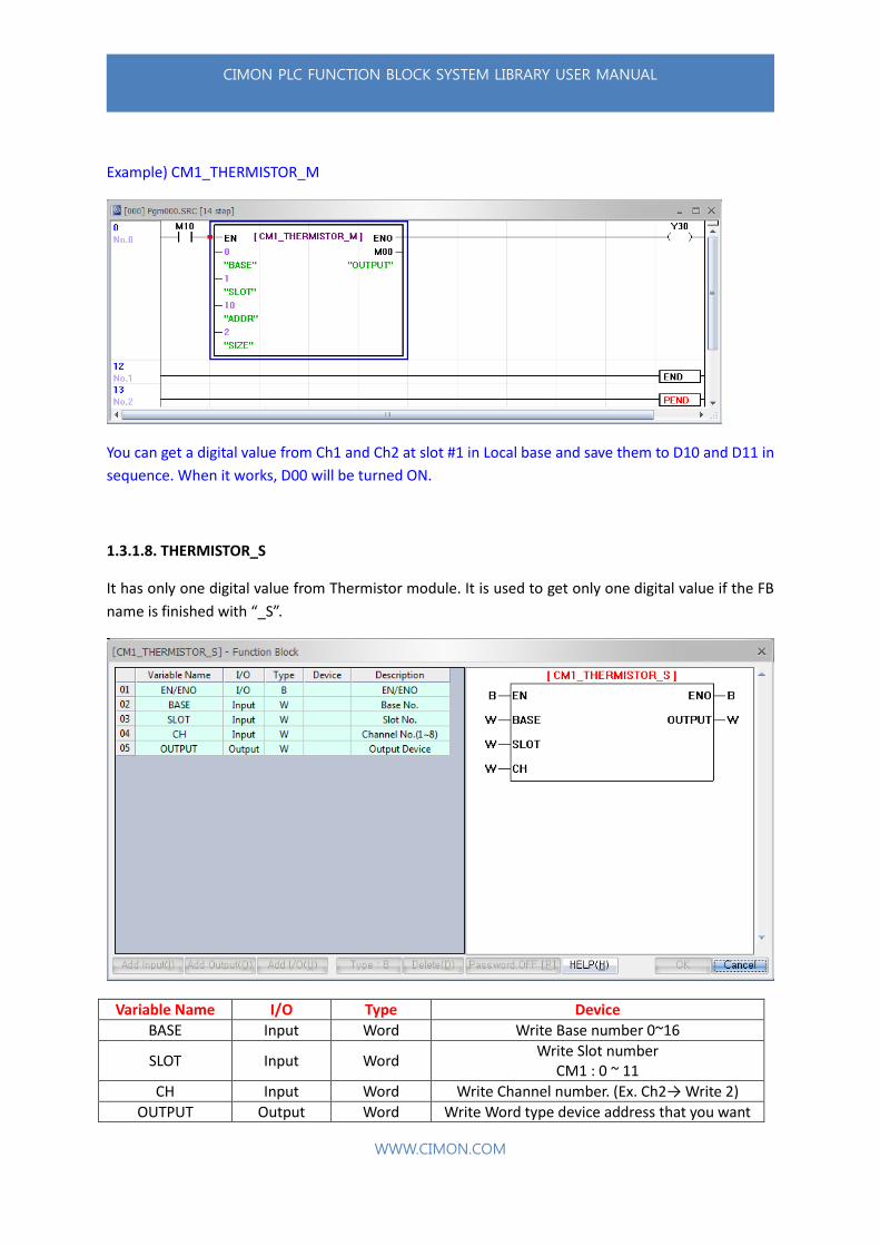
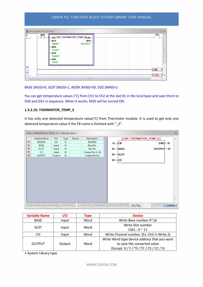
Example) CM1_THERMISTOR_M
You can get a digital value from Ch1 and Ch2 at slot #1 in Local base and save them to D10 and D11 in
sequence. When it works, D00 will be turned ON.
1.3.1.8. THERMISTOR_S
It has only one digital value from Thermistor module. It is used to get only one digital value if the FB
name is finished with “_S”.
Variable Name I/O Type Device
BASE Input Word Write Base number 0~16
SLOT Input Word Write Slot number
CM1 : 0 ~ 11
CH Input Word Write Channel number. (Ex. Ch2→ Write 2)
OUTPUT Output Word Write Word type device address that you want
CIMON PLC FUNCTION BLOCK SYSTEM LIBRARY USER MANUAL
WWW.CIMON.COM
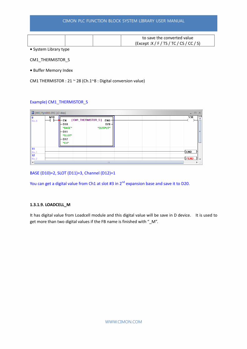
to save the converted value (Except :X / F / TS / TC / CS / CC / S)
• System Library type
CM1_THERMISTOR_S
• Buffer Memory Index
CM1 THERMISTOR : 21 ~ 28 (Ch.1~8 : Digital conversion value)
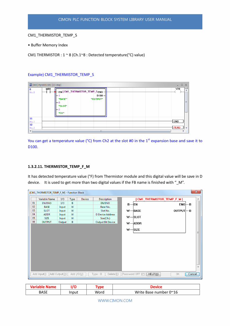
Example) CM1_THERMISTOR_S
BASE (D10)=2, SLOT (D11)=3, Channel (D12)=1
You can get a digital value from Ch1 at slot #3 in 2nd expansion base and save it to D20.
1.3.1.9. LOADCELL_M
It has digital value from Loadcell module and this digital value will be save in D device. It is used to
get more than two digital values if the FB name is finished with “_M”.

CIMON PLC FUNCTION BLOCK SYSTEM LIBRARY USER MANUAL
WWW.CIMON.COM
Variable Name I/O Type Device
BASE Input Word Write Base number 0~16
SLOT Input Word Write Slot number
CM1 : 0 ~ 11
ADDR Input Word Write D address. (Ex. D150 → Write 150)
SIZE Input Word Write number of Channel
(Ex. Ch.1→Write 1, Ch.1~3→Write 3)
OUTPUT Output Bit Not Used
Tip : The converted value is composed high and low. (Double Word)
For example, if you write 150 at the ADDR and 2 at the SIZE, the value will be saved as below.
Channel1 AD converted high word value → D150
Channel1 AD converted low word value → D151
Channel2 AD converted high word value → D152
Channel2 AD converted low word value → D153
• System Library type
CM1_LOADCELL_M
• Buffer Memory Index
CM1 Loadcell : 12 / 27 / 42 / 57 (Ch.1~4 : AD converted value)

CIMON PLC FUNCTION BLOCK SYSTEM LIBRARY USER MANUAL
WWW.CIMON.COM
Example) CM1_LOADCELL_M
You can get a digital value from Ch1 to Ch4 at slot #0 in 1st expansion base and save them to D2000,
D2001, D2002, and D2003 in sequence. When it works, M500 will be turned ON.
1.3.1.10. LOADCELL_S
It has only one detected weight value from Loadcell module. It is used to get only one detected
weight value if the FB name is finished with “_S”.
Variable Name I/O Type Device
BASE Input Word Write Base number 0~16
SLOT Input Word Write Slot number
CM1 : 0 ~ 11
CH Input Word Write Channel number. (Ex. Ch2→ Write 2)
OUTPUT Output Word Write Word type device address that you want
to save the converted value (Except :X / F / TS / TC / CS / CC / S)
CIMON PLC FUNCTION BLOCK SYSTEM LIBRARY USER MANUAL
WWW.CIMON.COM
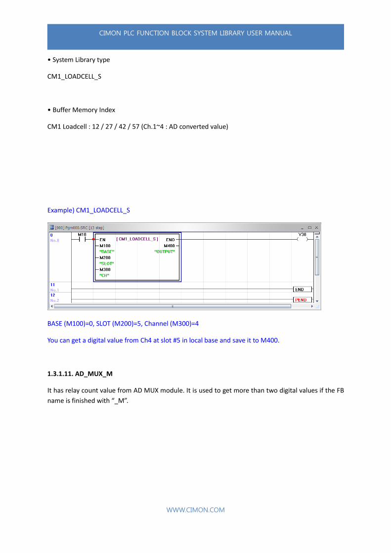
• System Library type
CM1_LOADCELL_S
• Buffer Memory Index
CM1 Loadcell : 12 / 27 / 42 / 57 (Ch.1~4 : AD converted value)
Example) CM1_LOADCELL_S
BASE (M100)=0, SLOT (M200)=5, Channel (M300)=4
You can get a digital value from Ch4 at slot #5 in local base and save it to M400.
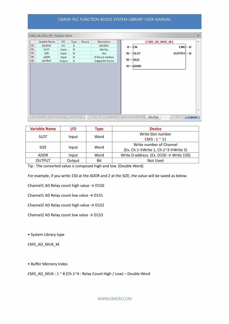
1.3.1.11. AD_MUX_M
It has relay count value from AD MUX module. It is used to get more than two digital values if the FB
name is finished with “_M”.
CIMON PLC FUNCTION BLOCK SYSTEM LIBRARY USER MANUAL
WWW.CIMON.COM
Variable Name I/O Type Device
SLOT Input Word Write Slot number
CM3 : 1 ~ 11
SIZE Input Word Write number of Channel
(Ex. Ch.1→Write 1, Ch.1~3→Write 3)
ADDR Input Word Write D address. (Ex. D150 → Write 150)
OUTPUT Output Bit Not Used
Tip : The converted value is composed high and low. (Double Word)
For example, if you write 150 at the ADDR and 2 at the SIZE, the value will be saved as below.
Channel1 AD Relay count high value → D150
Channel1 AD Relay count low value → D151
Channel2 AD Relay count high value → D152
Channel2 AD Relay count low value → D153
• System Library type
CM3_AD_MUX_M
• Buffer Memory Index
CM3_AD_MUX : 1 ~ 8 (Ch.1~4 : Relay Count High / Low) – Double Word

CIMON PLC FUNCTION BLOCK SYSTEM LIBRARY USER MANUAL
WWW.CIMON.COM
Example) CM3_AD_MUX_M
You can get Relay Count High and Low value from Ch1 and Ch2 at the slot#2 and save them to D100,
D101, D102, and D103 in sequence (2 Words per a channel). When it works, Y81 will be turned ON.
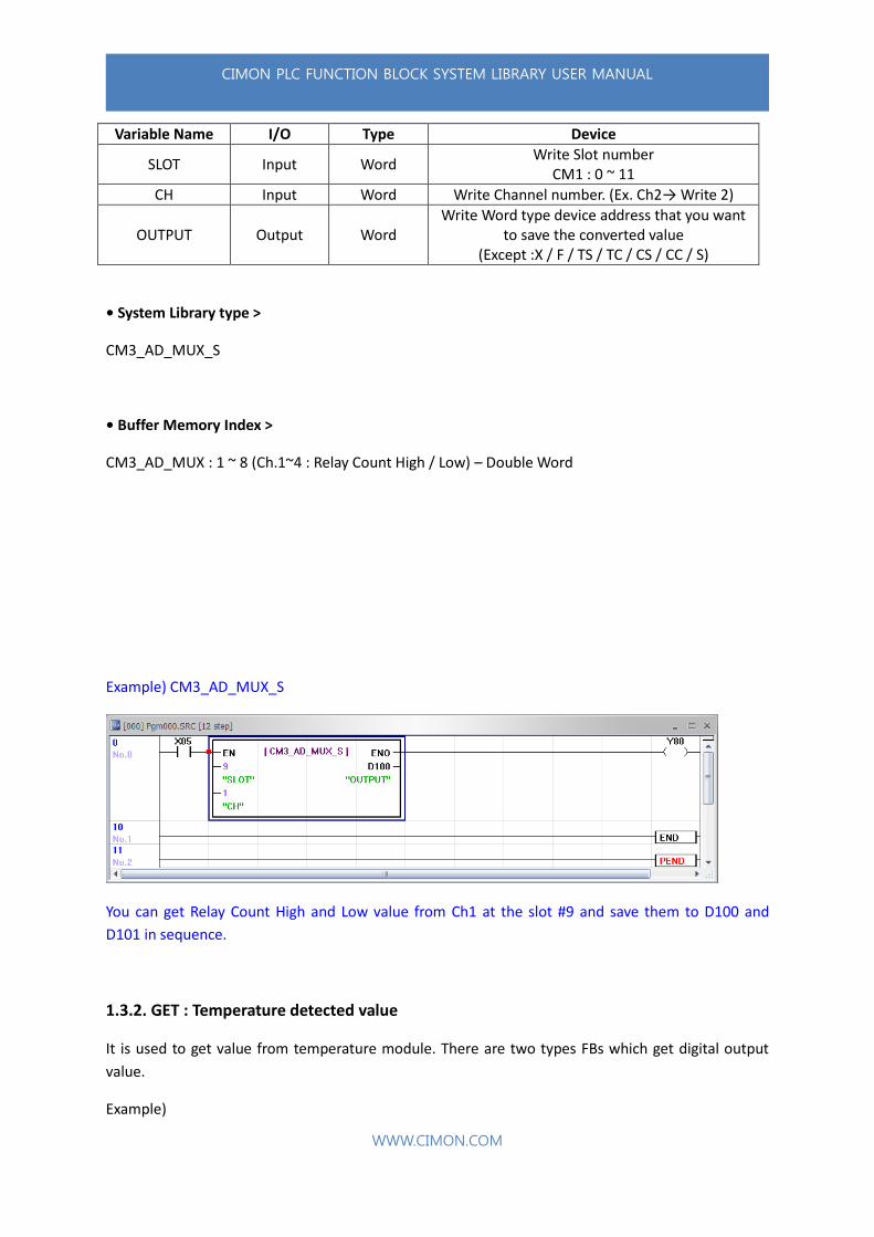
1.3.1.12. AD_MUX_S
It has relay count value from AD MUX module. It is used to get only one detected value if the FB
name is finished with “_S”.
CIMON PLC FUNCTION BLOCK SYSTEM LIBRARY USER MANUAL
WWW.CIMON.COM
Variable Name I/O Type Device
SLOT Input Word Write Slot number
CM1 : 0 ~ 11
CH Input Word Write Channel number. (Ex. Ch2→ Write 2)
OUTPUT Output Word Write Word type device address that you want
to save the converted value (Except :X / F / TS / TC / CS / CC / S)
• System Library type >
CM3_AD_MUX_S
• Buffer Memory Index >
CM3_AD_MUX : 1 ~ 8 (Ch.1~4 : Relay Count High / Low) – Double Word
Example) CM3_AD_MUX_S
You can get Relay Count High and Low value from Ch1 at the slot #9 and save them to D100 and
D101 in sequence.
1.3.2. GET : Temperature detected value
It is used to get value from temperature module. There are two types FBs which get digital output
value.
Example)

CIMON PLC FUNCTION BLOCK SYSTEM LIBRARY USER MANUAL
WWW.CIMON.COM
AD_M : It is used to get more than two digital values. D device is fixed to save this value. Type the
address on “ADDR” and type number of channels on “SIZE”. (If you want to get the values from
Channel 1~3, type 3. It will get a value from channel no.1 always.)
AD_S : It is used to get only one digital value. Output Device is fixed to save this value and can use
Word type device (D15, M70, K110 and etc.). Type channel number on “CH” (If you want to get a
value from Channel no.3, type 3)
1.3.2.1. RTD_TEMP_M
It has detected temperature value (°C) from RTD module and this digital value will be save in D device.
It is used to get more than two digital values if the FB name is finished with “_M”.

CIMON PLC FUNCTION BLOCK SYSTEM LIBRARY USER MANUAL
WWW.CIMON.COM
Variable Name I/O Type Device
BASE Input Word Write Base number 0~16
SLOT Input Word Write Slot number
CM1 : 0 ~ 11 / CM2 : 1 ~ 4 / CM3 : 1 ~ 11
ADDR Input Word Write D address. (Ex. D150 → Write 150)
SIZE Input Word Write number of Channel
(Ex. Ch.1→Write 1, Ch.1~3→Write 3)
OUTPUT Output Bit Not Used
If you write wrong SLOT number or BASE number, CPU will have an error.
• System Library type
CM1_RTD_TEMP_M / CM2_RTD_ TEMP_M / CM3_RTD_ TEMP_M
• Buffer Memory Index
CM1 RTD : 1 ~ 8 (Ch.1~8 : Detected temp. value)
CM2 RTD : 1 ~ 8 (Ch.1~8 : Detected temp. value)
CM3 RTD : 1 ~ 4 (Ch.1~4 : Detected temp. value)
Example) CM1_RTD_TEMP_M
BASE (M10)=5, SLOT (M20)=1, ADDR (M30)=5, SIZE(M40)=2
You can get temperature values(°C) from Ch1 and Ch2 at the slot #1 in the 5th expansion base and
save them to D5 and D6 in sequence. When it works, M900 will be turned ON.
Example) CM3_RTD_TEMP_M

CIMON PLC FUNCTION BLOCK SYSTEM LIBRARY USER MANUAL
WWW.CIMON.COM
You can get temperature values(°C) from Ch1 to Ch3 at the slot#5 and save them to D100, D101 and
D102 in sequence. When it works, M16 will be turned ON.
1.3.2.2. RTD_TEMP_S
It has only one detected temperature value(°C) from RTD module. It is used to get only one detected
temperature value if the FB name is finished with “_S”.

CIMON PLC FUNCTION BLOCK SYSTEM LIBRARY USER MANUAL
WWW.CIMON.COM
Variable Name I/O Type Device
BASE Input Word Write Base number 0~16
SLOT Input Word Write Slot number
CM1 : 0 ~ 11 / CM2 : 1 ~ 4 / CM3 : 1 ~ 11
CH Input Word Write Channel number. (Ex. Ch2→ Write 2)
OUTPUT Output Word Write Word type device address that you want
to save the converted value (Except :X / F / TS / TC / CS / CC / S)
If you write wrong SLOT number or BASE number, CPU will have an error.
• System Library type
CM1_RTD_TEMP_S / CM2_RTD_ TEMP_S / CM3_RTD_ TEMP_S
• Buffer Memory Index
CM1 RTD : 1 ~ 8 (Ch.1~8 : Detected temp. value)
CM2 RTD : 1 ~ 8 (Ch.1~8 : Detected temp. value)
CM3 RTD : 1 ~ 4 (Ch.1~4 : Detected temp. value)
Example) CM1_RTD_TEMP_S
BASE (D10)=2, SLOT (D11)=2
You can get a temperature value(°C) from Ch2 at the slot#2 in the local base and save it to D20 in
sequence.
Example) CM3_RTD_S

CIMON PLC FUNCTION BLOCK SYSTEM LIBRARY USER MANUAL
WWW.CIMON.COM
You can get a temperature value(°C) from Ch1 at the slot#2 and save it to M50.
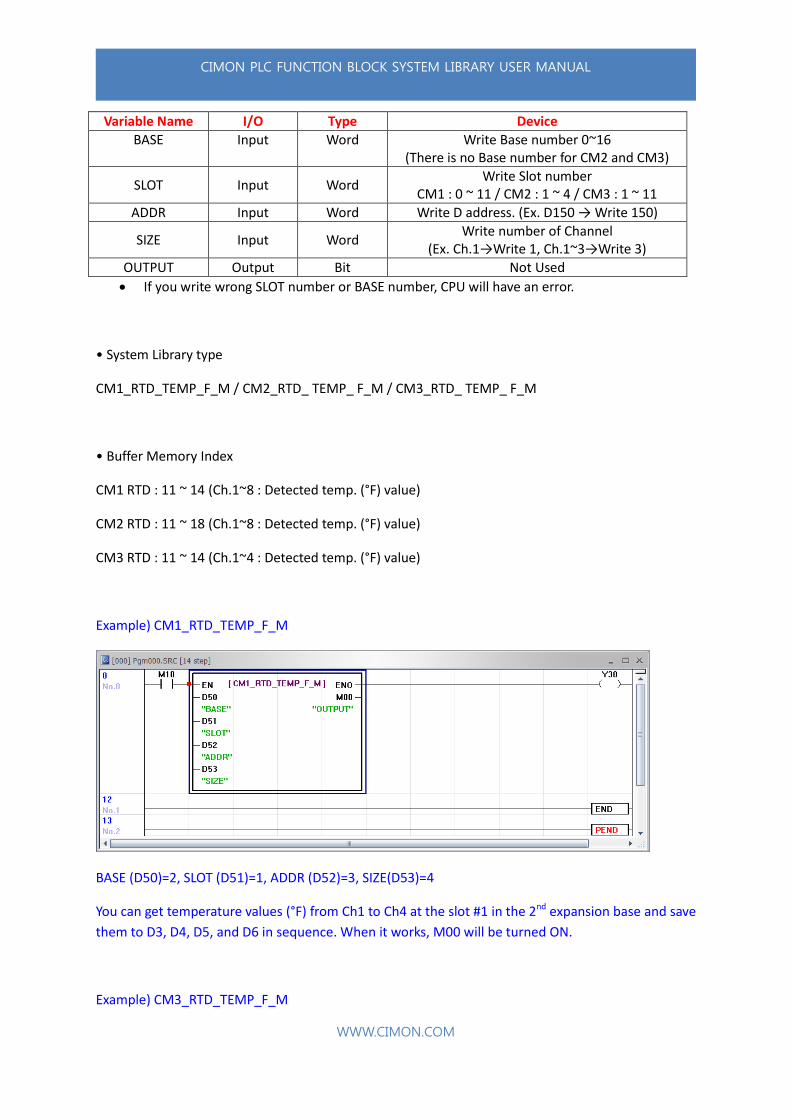
1.3.2.3. RTD_TEMP_F_M
It has detected temperature value(°F) from RTD module and this digital value will be save in D device.
It is used to get more than two digital values if the FB name is finished with “_M”.
CIMON PLC FUNCTION BLOCK SYSTEM LIBRARY USER MANUAL
WWW.CIMON.COM
Variable Name I/O Type Device
BASE Input Word Write Base number 0~16 (There is no Base number for CM2 and CM3)
SLOT Input Word Write Slot number
CM1 : 0 ~ 11 / CM2 : 1 ~ 4 / CM3 : 1 ~ 11
ADDR Input Word Write D address. (Ex. D150 → Write 150)
SIZE Input Word Write number of Channel
(Ex. Ch.1→Write 1, Ch.1~3→Write 3)
OUTPUT Output Bit Not Used
If you write wrong SLOT number or BASE number, CPU will have an error.
• System Library type
CM1_RTD_TEMP_F_M / CM2_RTD_ TEMP_ F_M / CM3_RTD_ TEMP_ F_M
• Buffer Memory Index
CM1 RTD : 11 ~ 14 (Ch.1~8 : Detected temp. (°F) value)
CM2 RTD : 11 ~ 18 (Ch.1~8 : Detected temp. (°F) value)
CM3 RTD : 11 ~ 14 (Ch.1~4 : Detected temp. (°F) value)
Example) CM1_RTD_TEMP_F_M
BASE (D50)=2, SLOT (D51)=1, ADDR (D52)=3, SIZE(D53)=4
You can get temperature values (°F) from Ch1 to Ch4 at the slot #1 in the 2nd expansion base and save
them to D3, D4, D5, and D6 in sequence. When it works, M00 will be turned ON.
Example) CM3_RTD_TEMP_F_M
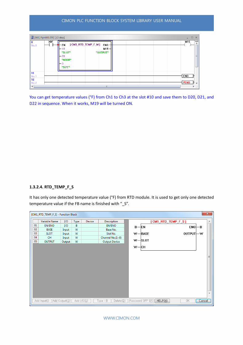
CIMON PLC FUNCTION BLOCK SYSTEM LIBRARY USER MANUAL
WWW.CIMON.COM
You can get temperature values (°F) from Ch1 to Ch3 at the slot #10 and save them to D20, D21, and
D22 in sequence. When it works, M19 will be turned ON.
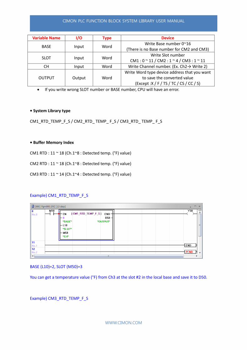
1.3.2.4. RTD_TEMP_F_S
It has only one detected temperature value (°F) from RTD module. It is used to get only one detected
temperature value if the FB name is finished with “_S”.
CIMON PLC FUNCTION BLOCK SYSTEM LIBRARY USER MANUAL
WWW.CIMON.COM
Variable Name I/O Type Device
BASE Input Word Write Base number 0~16
(There is no Base number for CM2 and CM3)
SLOT Input Word Write Slot number
CM1 : 0 ~ 11 / CM2 : 1 ~ 4 / CM3 : 1 ~ 11
CH Input Word Write Channel number. (Ex. Ch2→ Write 2)
OUTPUT Output Word Write Word type device address that you want
to save the converted value (Except :X / F / TS / TC / CS / CC / S)
If you write wrong SLOT number or BASE number, CPU will have an error.
• System Library type
CM1_RTD_TEMP_F_S / CM2_RTD_ TEMP_ F_S / CM3_RTD_ TEMP_ F_S
• Buffer Memory Index
CM1 RTD : 11 ~ 18 (Ch.1~8 : Detected temp. (°F) value)
CM2 RTD : 11 ~ 18 (Ch.1~8 : Detected temp. (°F) value)
CM3 RTD : 11 ~ 14 (Ch.1~4 : Detected temp. (°F) value)
Example) CM1_RTD_TEMP_F_S
BASE (L10)=2, SLOT (M50)=3
You can get a temperature value (°F) from Ch3 at the slot #2 in the local base and save it to D50.
Example) CM3_RTD_TEMP_F_S

CIMON PLC FUNCTION BLOCK SYSTEM LIBRARY USER MANUAL
WWW.CIMON.COM
You can get a temperature value (°F) from Ch1 at the slot #2 and save it to D100.
1.3.2.5. TC_TEMP_M
It has detected temperature value (°C) from TC module and this digital value will be save in D device.
It is used to get more than two digital values if the FB name is finished with “_M”.
CIMON PLC FUNCTION BLOCK SYSTEM LIBRARY USER MANUAL
WWW.CIMON.COM
Variable Name I/O Type Device
BASE Input Word Write Base number 0~16
(There is no Base number for CM2 and CM3)
SLOT Input Word Write Slot number
CM1 : 0 ~ 11 / CM2 : 1 ~ 4 / CM3 : 1 ~ 11
ADDR Input Word Write D address. (Ex. D150 → Write 150)
SIZE Input Word Write number of Channel
(Ex. Ch.1→Write 1, Ch.1~3→Write 3)
OUTPUT Output Bit Not Used
• System Library type
CM1_TC_TEMP_M / CM2_TC_TEMP_M / CM3_TC_TEMP_M
• Buffer Memory Index
CM1 TC : 1 ~ 8 (Ch.1~8 : Detected temperature(°C) value)
CM2 TC : 1 ~ 8 (Ch.1~8 : Detected temperature(°C)value)
CM3 TC : 1 ~ 4 (Ch.1~8 : Detected temperature(°C) value)
Exmple) CM1_TC_TEMP_M
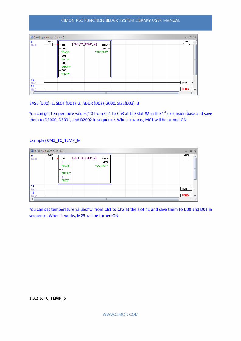
CIMON PLC FUNCTION BLOCK SYSTEM LIBRARY USER MANUAL
WWW.CIMON.COM
BASE (D00)=1, SLOT (D01)=2, ADDR (D02)=2000, SIZE(D03)=3
You can get temperature values(°C) from Ch1 to Ch3 at the slot #2 in the 1st expansion base and save
them to D2000, D2001, and D2002 in sequence. When it works, M01 will be turned ON.
Example) CM3_TC_TEMP_M
You can get temperature values(°C) from Ch1 to Ch2 at the slot #1 and save them to D00 and D01 in
sequence. When it works, M25 will be turned ON.
1.3.2.6. TC_TEMP_S
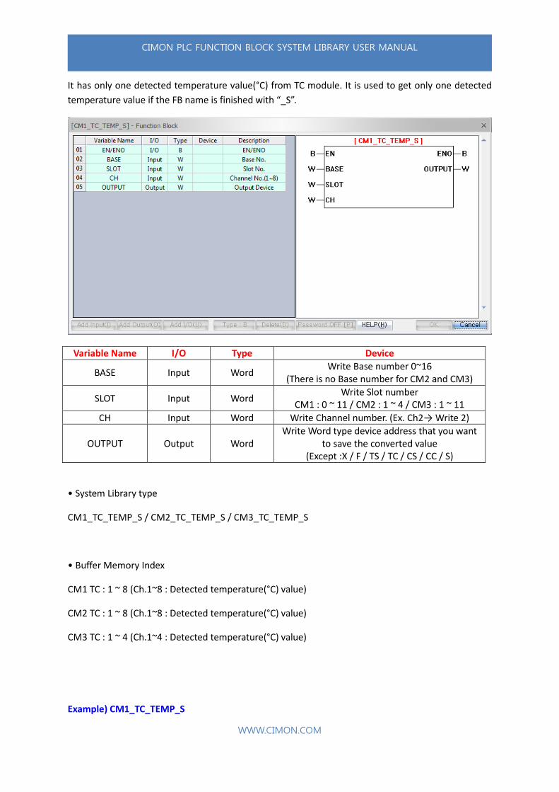
CIMON PLC FUNCTION BLOCK SYSTEM LIBRARY USER MANUAL
WWW.CIMON.COM
It has only one detected temperature value(°C) from TC module. It is used to get only one detected
temperature value if the FB name is finished with “_S”.
Variable Name I/O Type Device
BASE Input Word Write Base number 0~16
(There is no Base number for CM2 and CM3)
SLOT Input Word Write Slot number
CM1 : 0 ~ 11 / CM2 : 1 ~ 4 / CM3 : 1 ~ 11
CH Input Word Write Channel number. (Ex. Ch2→ Write 2)
OUTPUT Output Word Write Word type device address that you want
to save the converted value (Except :X / F / TS / TC / CS / CC / S)
• System Library type
CM1_TC_TEMP_S / CM2_TC_TEMP_S / CM3_TC_TEMP_S
• Buffer Memory Index
CM1 TC : 1 ~ 8 (Ch.1~8 : Detected temperature(°C) value)
CM2 TC : 1 ~ 8 (Ch.1~8 : Detected temperature(°C) value)
CM3 TC : 1 ~ 4 (Ch.1~4 : Detected temperature(°C) value)
Example) CM1_TC_TEMP_S

CIMON PLC FUNCTION BLOCK SYSTEM LIBRARY USER MANUAL
WWW.CIMON.COM
You can get a temperature values(°C) from Ch4 at the slot #2 in the local base and save it to M100.
Example) CM3_TC_S
You can get a temperature values(°C) from Ch1 at the slot #1 and save it to D10.
1.3.2.7. TC_TEMP_F_M

CIMON PLC FUNCTION BLOCK SYSTEM LIBRARY USER MANUAL
WWW.CIMON.COM
It has detected temperature value(°F) from TC module and this digital value will be save in D device.
It is used to get more than two digital values if the FB name is finished with “_M”.
Variable Name I/O Type Device
BASE Input Word Write Base number 0~16
(There is no Base number for CM2 and CM3)
SLOT Input Word Write Slot number
CM1 : 0 ~ 11 / CM2 : 1 ~ 4 / CM3 : 1 ~ 11
ADDR Input Word Write D address. (Ex. D150 → Write 150)
SIZE Input Word Write number of Channel
(Ex. Ch.1→Write 1, Ch.1~3→Write 3)
OUTPUT Output Bit Not Used
• System Library type
CM1_TC_TEMP_F_M / CM2_TC_TEMP_F_M / CM3_TC_TEMP_F_M
• Buffer Memory Index
CM1 TC : 11 ~ 18 (Ch.1~8 : Detected temperature(°F) value)
CM2 TC : 11 ~ 18 (Ch.1~8 : Detected temperature(°F)value)
CM3 TC : 11 ~ 14 (Ch.1~4 : Detected temperature(°F) value)
Example) CM1_TC_TEMP_F_M

CIMON PLC FUNCTION BLOCK SYSTEM LIBRARY USER MANUAL
WWW.CIMON.COM
BASE (M500)=0, SLOT(M600)=8, ADDR(M700)=100, SIZE(M800)=4
You can get temperature values (°F) from Ch1 to Ch4 at the slot #8 in the local base and save them to
D100, D101, D102, and D103 in sequence. When it works, M900 will be turned ON.
Example) CM3_TC_TEMP_F_M
You can get temperature values (°F) from Ch1 to Ch2 at the slot #3 and save them to D00 and D01 in
sequence. When it works, M14 will be turned ON.
1.3.2.8. TC_TEMP_F_S

CIMON PLC FUNCTION BLOCK SYSTEM LIBRARY USER MANUAL
WWW.CIMON.COM
It has only one detected temperature value(°F) from TC module. It is used to get only one detected
temperature value if the FB name is finished with “_S”.
Variable Name I/O Type Device
BASE Input Word Write Base number 0~16
(There is no Base number for CM2 and CM3)
SLOT Input Word Write Slot number
CM1 : 0 ~ 11 / CM2 : 1 ~ 4 / CM3 : 1 ~ 11
CH Input Word Write Channel number. (Ex. Ch2→ Write 2)
OUTPUT Output Word Write Word type device address that you want
to save the converted value (Except :X / F / TS / TC / CS / CC / S)
• System Library type
CM1_TC_TEMP_F_S / CM2_TC_TEMP_F_S / CM3_TC_TEMP_F_S
• Buffer Memory Index
CM1 TC : 11 ~ 18 (Ch.1~8 : Detected temperature(°F) value)
CM2 TC : 11 ~ 18 (Ch.1~8 : Detected temperature(°F) value)
CM3 TC : 11 ~ 14 (Ch.1~4 : Detected temperature(°F) value)
Example) CM1_TC_TEMP_F_S

CIMON PLC FUNCTION BLOCK SYSTEM LIBRARY USER MANUAL
WWW.CIMON.COM
BASE (D100)=1, SLOT (D90)=2
You can get a temperature value (°F) from Ch2 at the slot #1 in the local base and save it to D99.
Example) CM3_TC_TEMP_F_S
You can get a temperature value (°F) from Ch2 at the slot #8 and save it to D45.
1.3.2.9. THERMISTOR_TEMP_M
CIMON PLC FUNCTION BLOCK SYSTEM LIBRARY USER MANUAL
WWW.CIMON.COM
It has detected temperature value (°C) from Thermistor module and this digital value will be save in D
device. It is used to get more than two digital values if the FB name is finished with “_M”.
Variable Name I/O Type Device
BASE Input Word Write Base number 0~16
SLOT Input Word Write Slot number
CM1 : 0 ~ 11
ADDR Input Word Write D address. (Ex. D150 → Write 150)
SIZE Input Word Write number of Channel
(Ex. Ch.1→Write 1, Ch.1~3→Write 3)
OUTPUT Output Bit Not Used
• System Library type
CM1_THERMISTOR_TEMP_M
• Buffer Memory Index
CM1 THERMISTOR : 1 ~ 8 (Ch.1~8 : Detected temperature(°C) value)
Example) CM1_THERMISTOR_TEMP_M
CIMON PLC FUNCTION BLOCK SYSTEM LIBRARY USER MANUAL
WWW.CIMON.COM
BASE (M10)=0, SLOT (M20)=1, ADDR (M30)=50, SIZE (M40)=2
You can get temperature values (°C) from Ch1 to Ch2 at the slot #1 in the local base and save them to
D50 and D51 in sequence. When it works, M50 will be turned ON.
1.3.2.10. THERMISTOR_TEMP_S
It has only one detected temperature value(°C) from Thermistor module. It is used to get only one
detected temperature value if the FB name is finished with “_S”.
Variable Name I/O Type Device
BASE Input Word Write Base number 0~16
SLOT Input Word Write Slot number
CM1 : 0 ~ 11
CH Input Word Write Channel number. (Ex. Ch2→ Write 2)
OUTPUT Output Word Write Word type device address that you want
to save the converted value (Except :X / F / TS / TC / CS / CC / S)
• System Library type
CIMON PLC FUNCTION BLOCK SYSTEM LIBRARY USER MANUAL
WWW.CIMON.COM
CM1_THERMISTOR_TEMP_S
• Buffer Memory Index
CM1 THERMISTOR : 1 ~ 8 (Ch.1~8 : Detected temperature(°C) value)
Example) CM1_THERMISTOR_TEMP_S
You can get a temperature value (°C) from Ch2 at the slot #0 in the 1st expansion base and save it to
D100.
1.3.2.11. THERMISTOR_TEMP_F_M
It has detected temperature value (°F) from Thermistor module and this digital value will be save in D
device. It is used to get more than two digital values if the FB name is finished with “_M”.
Variable Name I/O Type Device
BASE Input Word Write Base number 0~16
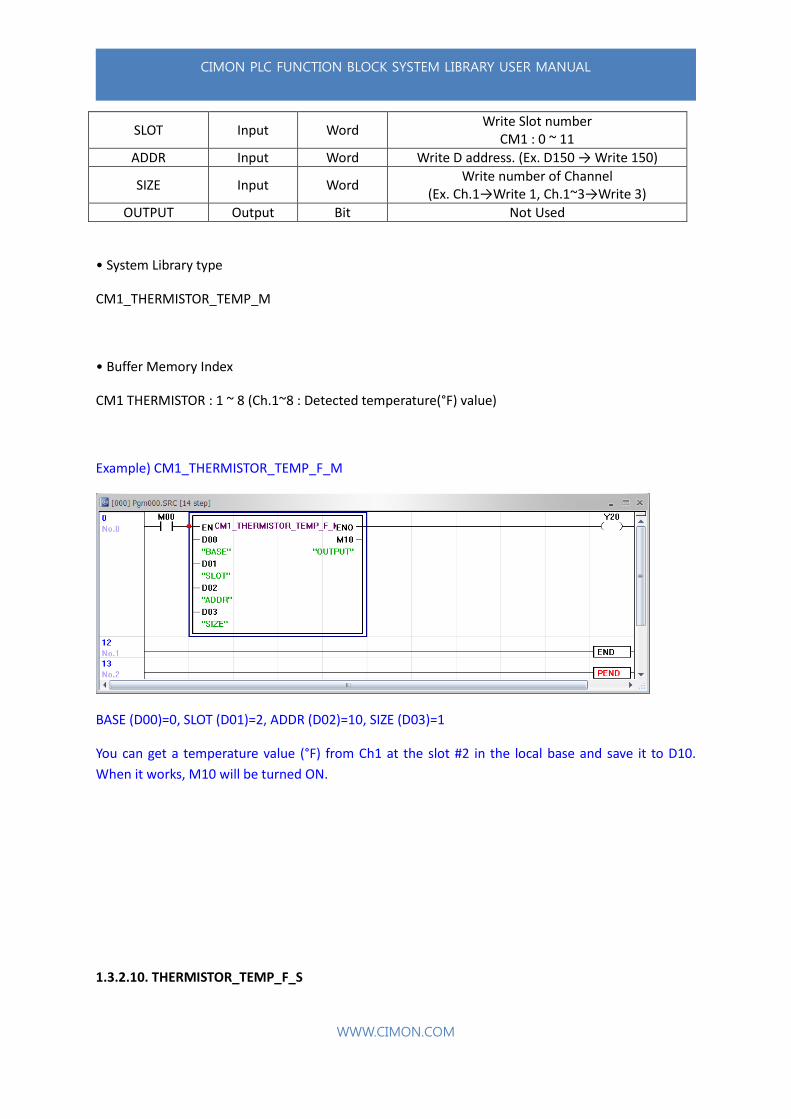
CIMON PLC FUNCTION BLOCK SYSTEM LIBRARY USER MANUAL
WWW.CIMON.COM
SLOT Input Word Write Slot number
CM1 : 0 ~ 11
ADDR Input Word Write D address. (Ex. D150 → Write 150)
SIZE Input Word Write number of Channel
(Ex. Ch.1→Write 1, Ch.1~3→Write 3)
OUTPUT Output Bit Not Used
• System Library type
CM1_THERMISTOR_TEMP_M
• Buffer Memory Index
CM1 THERMISTOR : 1 ~ 8 (Ch.1~8 : Detected temperature(°F) value)
Example) CM1_THERMISTOR_TEMP_F_M
BASE (D00)=0, SLOT (D01)=2, ADDR (D02)=10, SIZE (D03)=1
You can get a temperature value (°F) from Ch1 at the slot #2 in the local base and save it to D10.
When it works, M10 will be turned ON.
1.3.2.10. THERMISTOR_TEMP_F_S
CIMON PLC FUNCTION BLOCK SYSTEM LIBRARY USER MANUAL
WWW.CIMON.COM
It has only one detected temperature value(°F) from Thermistor module. It is used to get only one
detected temperature value if the FB name is finished with “_S”.
Variable Name I/O Type Device
BASE Input Word Write Base number 0~16
SLOT Input Word Write Slot number
CM1 : 0 ~ 11
CH Input Word Write Channel number. (Ex. Ch2→ Write 2)
OUTPUT Output Word Write Word type device address that you want
to save the converted value (Except :X / F / TS / TC / CS / CC / S)
• System Library type
CM1_THERMISTOR_TEMP_F_S
• Buffer Memory Index
CM1 THERMISTOR : 1 ~ 8 (Ch.1~8 : Detected temperature(°F) value)
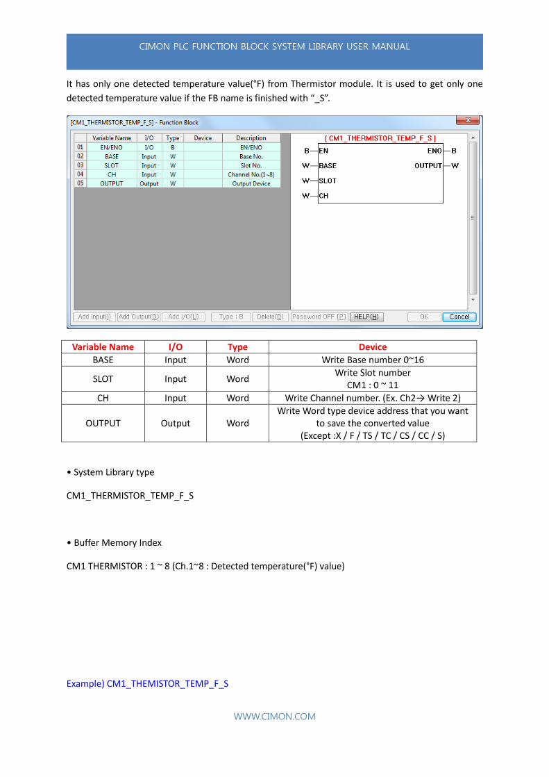
Example) CM1_THEMISTOR_TEMP_F_S
CIMON PLC FUNCTION BLOCK SYSTEM LIBRARY USER MANUAL
WWW.CIMON.COM
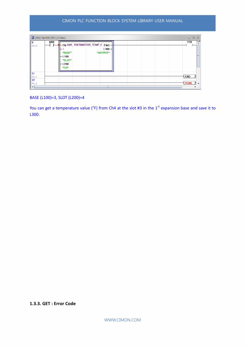
BASE (L100)=3, SLOT (L200)=4
You can get a temperature value (°F) from Ch4 at the slot #3 in the 1st expansion base and save it to
L300.
1.3.3. GET : Error Code

CIMON PLC FUNCTION BLOCK SYSTEM LIBRARY USER MANUAL
WWW.CIMON.COM
It is used to get an error code from Special module. RTD, TC and Thermistor Error Library can have
more than 2 buffer memory.
• GET : ERROR Library List
Group CPU Library name Buffer
Memory Description
GET ERROR
CM1
CM1_AD_ERROR 19 AD Error code
CM1_AD16_ERROR 62 AD 16Ch. Error code
CM1_DA_ERROR 9 DA Error code
CM1_RTD_ERROR 31~38 RTD Error code
CM1_RTD_MAX_MIN_ERROR 50 RTD Max./Min. setting Error (Buffer memory 49 must be set)
CM1_TC_ERROR 31~34 TC Error code
CM1_TC_MAX_MIN_ERROR 50 TC Max./Min. setting Error (Buffer memory 49 must be set)
CM1_THERMISTOR_ERROR 31~38 THERMISTOR Error code
CM2
CM2_AD_ERROR 19 AD Error code
CM2_DA_ERROR 9 DA Error code
CM2_ADDA_AD_ERROR 11 ADDA AD Error code
CM2_ADDA_DA_ERROR 37 ADDA DA Error code
CM2_RTD_ERROR 31~38 RTD Error code
CM2_RTD_MAX_MIN_ERROR 50 RTD Max./Min. setting Error (Buffer memory 49 must be set)
CM2_TC_ERROR 31~38 TC Error code
CM2_TC_MAX_MIN_ERROR 50 TC Max./Min. setting Error (Buffer memory 49 must be set)
CM3
CM3_AD_ERROR 37 AD Error code
CM3_DA_ERROR 21 DA Error code
CM3_ADDA_ERROR 29 ADDA Error code
CM3_RTD_ERROR 31~38 RTD Error code
CM3_RTD_MAX_MIN_ERROR 50 RTD Max./Min. setting Error (Buffer memory 49 must be set)
CM3_TC_ERROR 31~38 TC Error code
CM3_TC_MAX_MIN_ERROR 50 TC Max./Min. setting Error (Buffer memory 49 must be set)
CM3_AD_MUX_ERROR 15 AD MUX Error code
1.3.3.1. ERROR– Special modules
CIMON PLC FUNCTION BLOCK SYSTEM LIBRARY USER MANUAL
WWW.CIMON.COM
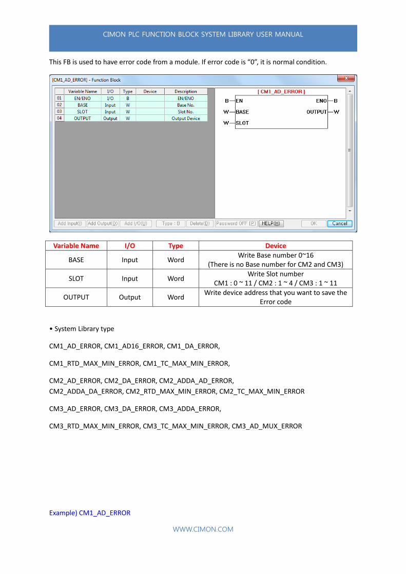
This FB is used to have error code from a module. If error code is “0”, it is normal condition.
Variable Name I/O Type Device
BASE Input Word Write Base number 0~16
(There is no Base number for CM2 and CM3)
SLOT Input Word Write Slot number
CM1 : 0 ~ 11 / CM2 : 1 ~ 4 / CM3 : 1 ~ 11
OUTPUT Output Word Write device address that you want to save the
Error code
• System Library type
CM1_AD_ERROR, CM1_AD16_ERROR, CM1_DA_ERROR,
CM1_RTD_MAX_MIN_ERROR, CM1_TC_MAX_MIN_ERROR,
CM2_AD_ERROR, CM2_DA_ERROR, CM2_ADDA_AD_ERROR,
CM2_ADDA_DA_ERROR, CM2_RTD_MAX_MIN_ERROR, CM2_TC_MAX_MIN_ERROR
CM3_AD_ERROR, CM3_DA_ERROR, CM3_ADDA_ERROR,
CM3_RTD_MAX_MIN_ERROR, CM3_TC_MAX_MIN_ERROR, CM3_AD_MUX_ERROR
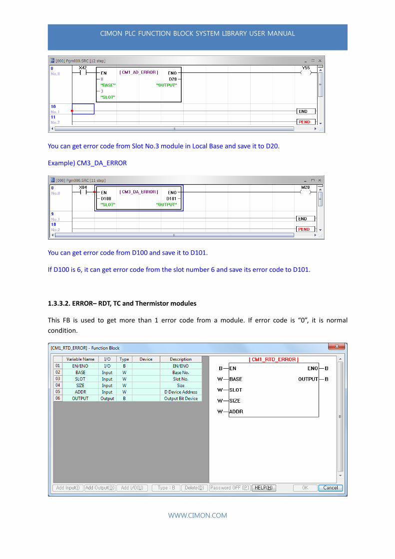
Example) CM1_AD_ERROR
CIMON PLC FUNCTION BLOCK SYSTEM LIBRARY USER MANUAL
WWW.CIMON.COM
You can get error code from Slot No.3 module in Local Base and save it to D20.
Example) CM3_DA_ERROR
You can get error code from D100 and save it to D101.
If D100 is 6, it can get error code from the slot number 6 and save its error code to D101.
1.3.3.2. ERROR– RDT, TC and Thermistor modules
This FB is used to get more than 1 error code from a module. If error code is “0”, it is normal
condition.

CIMON PLC FUNCTION BLOCK SYSTEM LIBRARY USER MANUAL
WWW.CIMON.COM
Variable Name I/O Type Device
BASE Input Word Write Base number 0~16 (There is no Base number for CM2 and CM3)
SLOT Input Word Write Slot number
CM1 : 0 ~ 11
SIZE Input Word Write number of Channel
(Ex. Ch.1→Write 1, Ch.1~3→Write 3)
ADDR Input Word Write D address. (Ex. D150 → Write 150)
OUTPUT Output Bit Bit will be turned ON if it works.
• System Library type
CM1_RTD_ERROR / CM1_TC_ERROR
CM2_RTD_ERROR / CM2_TC_ERROR
CM3_RTD_ERROR / CM3_TC_ERROR
Example) CM1_RTD_ERROR
In case of D00: 1(1st expansion Base), D01: 2(Slot number2), D02: 2(Ch1 and Ch2), D03: 100, you can
have two error codes from Channel 1 and 2 at Slot number 2 in 1st Expansion Base and save them to
D100 and D101 each. If it works properly, M100 bit will be turned ON. (Slot number starts from 0)
CIMON PLC FUNCTION BLOCK SYSTEM LIBRARY USER MANUAL
WWW.CIMON.COM
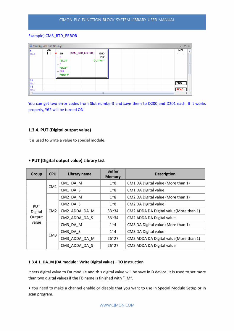
Example) CM3_RTD_ERROR
You can get two error codes from Slot number3 and save them to D200 and D201 each. If it works
properly, Y62 will be turned ON.
1.3.4. PUT (Digital output value)
It is used to write a value to special module.
• PUT (Digital output value) Library List
Group CPU Library name Buffer
Memory Description
PUT Digital Output value
CM1 CM1_DA_M 1~8 CM1 DA Digital value (More than 1)
CM1_DA_S 1~8 CM1 DA Digital value
CM2_DA_M 1~8 CM2 DA Digital value (More than 1)
CM2
CM2_DA_S 1~8 CM2 DA Digital value
CM2_ADDA_DA_M 33~34 CM2 ADDA DA Digital value(More than 1)
CM2_ADDA_DA_S 33~34 CM2 ADDA DA Digital value
CM3
CM3_DA_M 1~4 CM3 DA Digital value (More than 1)
CM3_DA_S 1~4 CM3 DA Digital value
CM3_ADDA_DA_M 26~27 CM3 ADDA DA Digital value(More than 1)
CM3_ADDA_DA_S 26~27 CM3 ADDA DA Digital value
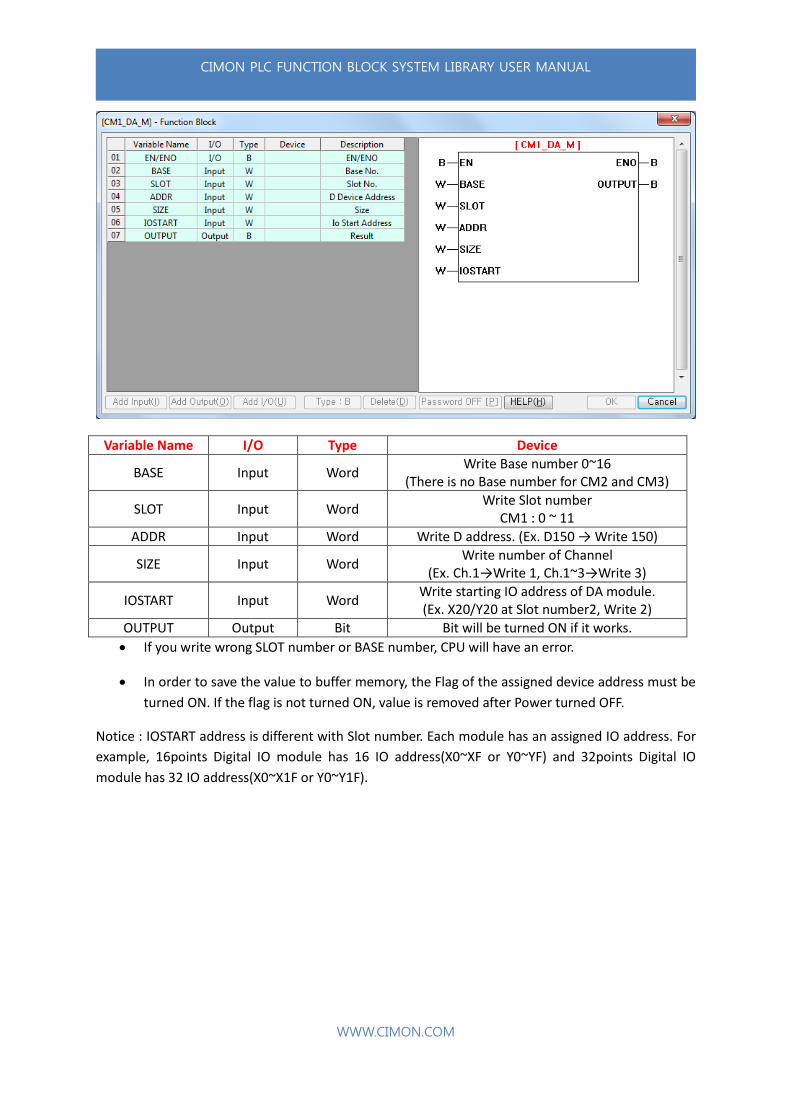
1.3.4.1. DA_M (DA module : Write Digital value) – TO Instruction
It sets digital value to DA module and this digital value will be save in D device. It is used to set more
than two digital values if the FB name is finished with “_M”.
• You need to make a channel enable or disable that you want to use in Special Module Setup or in
scan program.
CIMON PLC FUNCTION BLOCK SYSTEM LIBRARY USER MANUAL
WWW.CIMON.COM
Variable Name I/O Type Device
BASE Input Word Write Base number 0~16
(There is no Base number for CM2 and CM3)
SLOT Input Word Write Slot number
CM1 : 0 ~ 11
ADDR Input Word Write D address. (Ex. D150 → Write 150)
SIZE Input Word Write number of Channel
(Ex. Ch.1→Write 1, Ch.1~3→Write 3)
IOSTART Input Word Write starting IO address of DA module. (Ex. X20/Y20 at Slot number2, Write 2)
OUTPUT Output Bit Bit will be turned ON if it works.
If you write wrong SLOT number or BASE number, CPU will have an error.
In order to save the value to buffer memory, the Flag of the assigned device address must be
turned ON. If the flag is not turned ON, value is removed after Power turned OFF.
Notice : IOSTART address is different with Slot number. Each module has an assigned IO address. For
example, 16points Digital IO module has 16 IO address(X0~XF or Y0~YF) and 32points Digital IO
module has 32 IO address(X0~X1F or Y0~Y1F).
CIMON PLC FUNCTION BLOCK SYSTEM LIBRARY USER MANUAL
WWW.CIMON.COM
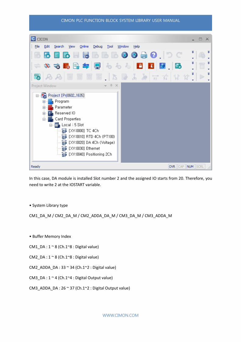
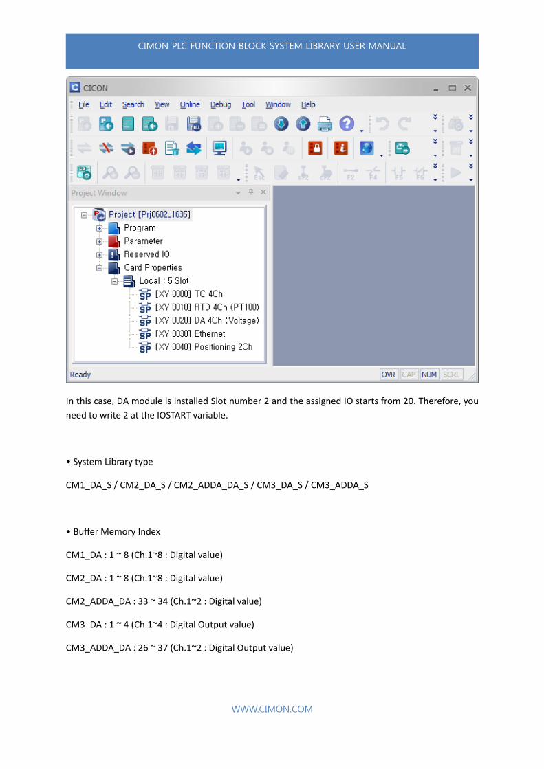
In this case, DA module is installed Slot number 2 and the assigned IO starts from 20. Therefore, you
need to write 2 at the IOSTART variable.
• System Library type
CM1_DA_M / CM2_DA_M / CM2_ADDA_DA_M / CM3_DA_M / CM3_ADDA_M
• Buffer Memory Index
CM1_DA : 1 ~ 8 (Ch.1~8 : Digital value)
CM2_DA : 1 ~ 8 (Ch.1~8 : Digital value)
CM2_ADDA_DA : 33 ~ 34 (Ch.1~2 : Digital value)
CM3_DA : 1 ~ 4 (Ch.1~4 : Digital Output value)
CM3_ADDA_DA : 26 ~ 37 (Ch.1~2 : Digital Output value)
CIMON PLC FUNCTION BLOCK SYSTEM LIBRARY USER MANUAL
WWW.CIMON.COM
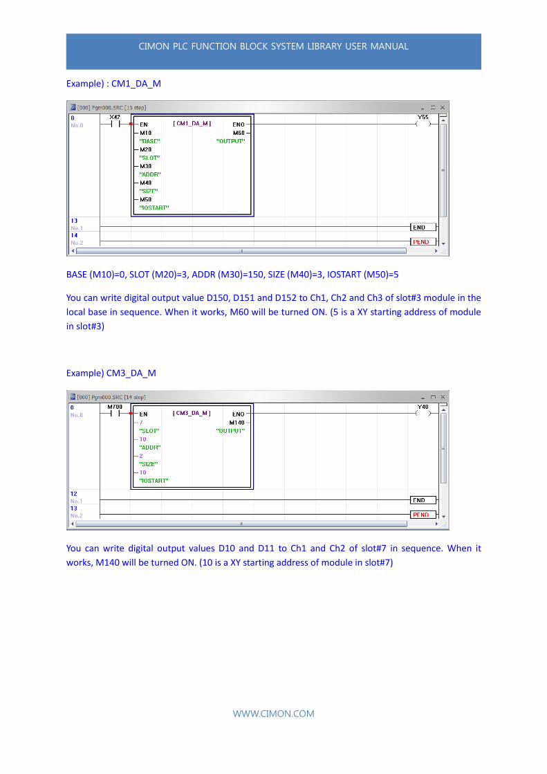
Example) : CM1_DA_M
BASE (M10)=0, SLOT (M20)=3, ADDR (M30)=150, SIZE (M40)=3, IOSTART (M50)=5
You can write digital output value D150, D151 and D152 to Ch1, Ch2 and Ch3 of slot#3 module in the
local base in sequence. When it works, M60 will be turned ON. (5 is a XY starting address of module
in slot#3)
Example) CM3_DA_M
You can write digital output values D10 and D11 to Ch1 and Ch2 of slot#7 in sequence. When it
works, M140 will be turned ON. (10 is a XY starting address of module in slot#7)
CIMON PLC FUNCTION BLOCK SYSTEM LIBRARY USER MANUAL
WWW.CIMON.COM
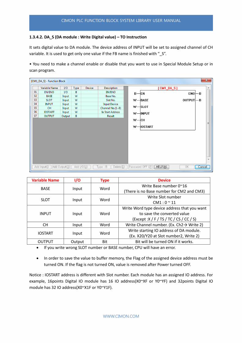
1.3.4.2. DA_S (DA module : Write Digital value) – TO Instruction
It sets digital value to DA module. The device address of INPUT will be set to assigned channel of CH
variable. It is used to get only one value if the FB name is finished with “_S”.
• You need to make a channel enable or disable that you want to use in Special Module Setup or in
scan program.
Variable Name I/O Type Device
BASE Input Word Write Base number 0~16
(There is no Base number for CM2 and CM3)
SLOT Input Word Write Slot number
CM1 : 0 ~ 11
INPUT Input Word Write Word type device address that you want
to save the converted value (Except :X / F / TS / TC / CS / CC / S)
CH Input Word Write Channel number. (Ex. Ch2→ Write 2)
IOSTART Input Word Write starting IO address of DA module. (Ex. X20/Y20 at Slot number2, Write 2)
OUTPUT Output Bit Bit will be turned ON if it works.
If you write wrong SLOT number or BASE number, CPU will have an error.
In order to save the value to buffer memory, the Flag of the assigned device address must be
turned ON. If the flag is not turned ON, value is removed after Power turned OFF.
Notice : IOSTART address is different with Slot number. Each module has an assigned IO address. For
example, 16points Digital IO module has 16 IO address(X0~XF or Y0~YF) and 32points Digital IO
module has 32 IO address(X0~X1F or Y0~Y1F).
CIMON PLC FUNCTION BLOCK SYSTEM LIBRARY USER MANUAL
WWW.CIMON.COM
In this case, DA module is installed Slot number 2 and the assigned IO starts from 20. Therefore, you
need to write 2 at the IOSTART variable.
• System Library type
CM1_DA_S / CM2_DA_S / CM2_ADDA_DA_S / CM3_DA_S / CM3_ADDA_S
• Buffer Memory Index
CM1_DA : 1 ~ 8 (Ch.1~8 : Digital value)
CM2_DA : 1 ~ 8 (Ch.1~8 : Digital value)
CM2_ADDA_DA : 33 ~ 34 (Ch.1~2 : Digital value)
CM3_DA : 1 ~ 4 (Ch.1~4 : Digital Output value)
CM3_ADDA_DA : 26 ~ 37 (Ch.1~2 : Digital Output value)

CIMON PLC FUNCTION BLOCK SYSTEM LIBRARY USER MANUAL
WWW.CIMON.COM
Example) CM1_DA_S
BASE (D10)=0, SLOT (D11)=5, INPUT (D12)=5000, Channel (D13)=4, IOSTART (D14)=6
You can write digital output value 5000 to Ch4 of slot#5 module in local base. When it works, Y40 will
be turned ON. (6 is a XY starting address of module in slot#5)
Example) CM3_DA_S
You can write digital output values D100 to Ch2 of slot#2 module. When it works, Y20 will be turned
ON. (4 is a XY starting address of module in slot#2)

CIMON PLC FUNCTION BLOCK SYSTEM LIBRARY USER MANUAL
WWW.CIMON.COM
1.3.5. PUT : ETC
It is used to write a value to special module.
• PUT (Digital output value) Library List
Group CPU Library name Buffer
Memory Description
PUT ETC
CM1 CM1_LOADCELL_CODE 7/22/37/52 CM1 LOADCELL Command Main Code
CM3 CM3_AD_MUX_ENABLE 0 CM3 AD MUX Channel Enable/Disable set
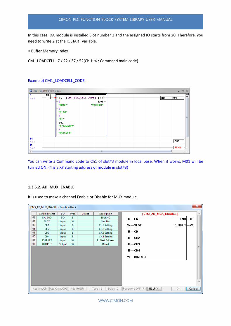
1.3.5.1. LOADCELL_CODE
It sets Command main code to Loadcell module. Only one Command main code can be set up for a
channel in Function Block.
• You need to make a channel enable or disable that you want to use in Special Module Setup or in
scan program.
Variable Name I/O Type Device
BASE Input Word Write Base number 0~16
(There is no Base number for CM2 and CM3)
SLOT Input Word Write Slot number
CM1 : 0 ~ 11
CH Input Word Write Channel number. (Ex. Ch2→ Write 2)
COMMAND Input Word Write Command main code
(Ex. Error Clear, Write 1)
IOSTART Input Word Write starting IO address of DA module. (Ex. X20/Y20 at Slot number2, Write 2)
OUTPUT Output Bit Bit will be turned ON if it works.

CIMON PLC FUNCTION BLOCK SYSTEM LIBRARY USER MANUAL
WWW.CIMON.COM
If you write wrong SLOT number or BASE number, CPU will have an error.
In order to save the value to buffer memory, the Flag of the assigned device address must be
turned ON. If the flag is not turned ON, value is removed after Power turned OFF.
Command main code
Code Name Description
0000H(0) None None
0001H(1) Error Clear Clear error code. Error code will become ‘0’ and channel error (Buffer XA~XD) will be turned OFF.
0002H(2) Run Batch Run Batch program. The Batch program must be assigned at the Weighting mode.
0003H(3) Stop Batch Stop running Batch program.
0004H(4) Calibration Calibrate current measured weight to zero.
0005H(5) Set Command sub code
Assign current measured weight to Command sub code low/high. It must be done after calibration
0006H(6) Save calibration Save calibrated data to memory. The saved parameter will be applied automatically when Power is ON.
0007H(7) Zero Clear Make Zero applied weight(Gross weight) Zero point
0008H(8) Tare Clear Make Tare applied weight(Net weight) Zero point
0009H(9) Change set value Change current operating parameter and Batch parameter value to buffer memory value.
Notice : IOSTART address is different with Slot number. Each module has an assigned IO address. For
example, 16points Digital IO module has 16 IO address(X0~XF or Y0~YF) and 32points Digital IO
module has 32 IO address(X0~X1F or Y0~Y1F).
CIMON PLC FUNCTION BLOCK SYSTEM LIBRARY USER MANUAL
WWW.CIMON.COM
In this case, DA module is installed Slot number 2 and the assigned IO starts from 20. Therefore, you
need to write 2 at the IOSTART variable.
• Buffer Memory Index
CM1 LOADCELL : 7 / 22 / 37 / 52(Ch.1~4 : Command main code)
Example) CM1_LOADCELL_CODE
You can write a Command code to Ch1 of slot#3 module in local base. When it works, M01 will be
turned ON. (4 is a XY starting address of module in slot#3)
1.3.5.2. AD_MUX_ENABLE
It is used to make a channel Enable or Disable for MUX module.
CIMON PLC FUNCTION BLOCK SYSTEM LIBRARY USER MANUAL
WWW.CIMON.COM
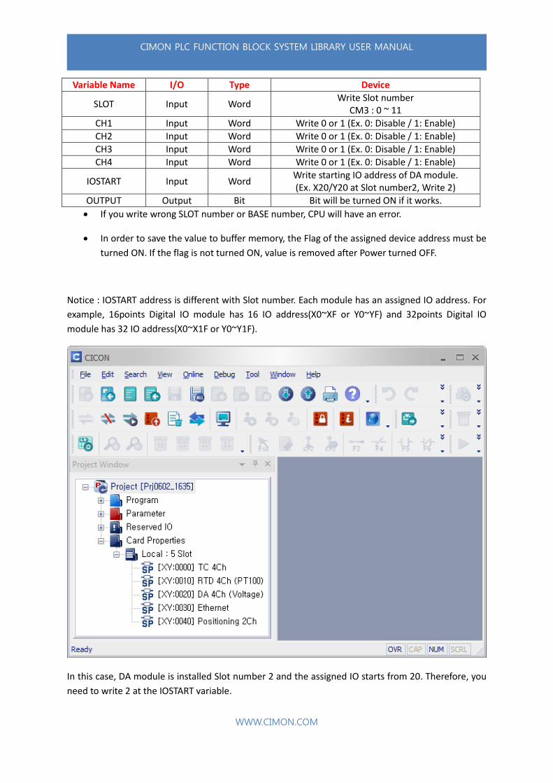
Variable Name I/O Type Device
SLOT Input Word Write Slot number
CM3 : 0 ~ 11
CH1 Input Word Write 0 or 1 (Ex. 0: Disable / 1: Enable)
CH2 Input Word Write 0 or 1 (Ex. 0: Disable / 1: Enable)
CH3 Input Word Write 0 or 1 (Ex. 0: Disable / 1: Enable)
CH4 Input Word Write 0 or 1 (Ex. 0: Disable / 1: Enable)
IOSTART Input Word Write starting IO address of DA module. (Ex. X20/Y20 at Slot number2, Write 2)
OUTPUT Output Bit Bit will be turned ON if it works.
If you write wrong SLOT number or BASE number, CPU will have an error.
In order to save the value to buffer memory, the Flag of the assigned device address must be
turned ON. If the flag is not turned ON, value is removed after Power turned OFF.
Notice : IOSTART address is different with Slot number. Each module has an assigned IO address. For
example, 16points Digital IO module has 16 IO address(X0~XF or Y0~YF) and 32points Digital IO
module has 32 IO address(X0~X1F or Y0~Y1F).
In this case, DA module is installed Slot number 2 and the assigned IO starts from 20. Therefore, you
need to write 2 at the IOSTART variable.
CIMON PLC FUNCTION BLOCK SYSTEM LIBRARY USER MANUAL
WWW.CIMON.COM
• Buffer Memory Index
CM3 AD MUX : 0(Ch.1~4 : Channel Enable / Disable)
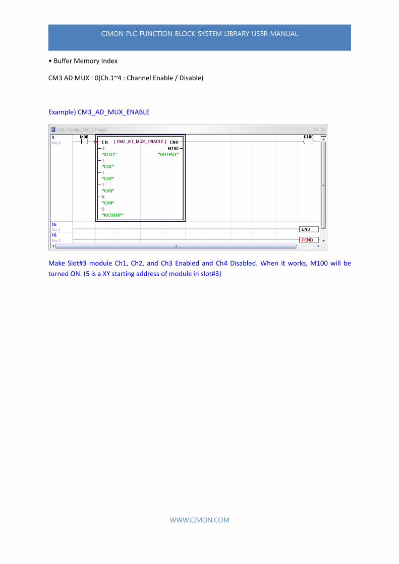
Example) CM3_AD_MUX_ENABLE
Make Slot#3 module Ch1, Ch2, and Ch3 Enabled and Ch4 Disabled. When it works, M100 will be
turned ON. (5 is a XY starting address of module in slot#3)
CIMON PLC FUNCTION BLOCK SYSTEM LIBRARY USER MANUAL
WWW.CIMON.COM
1.3.6. High Speed Counter
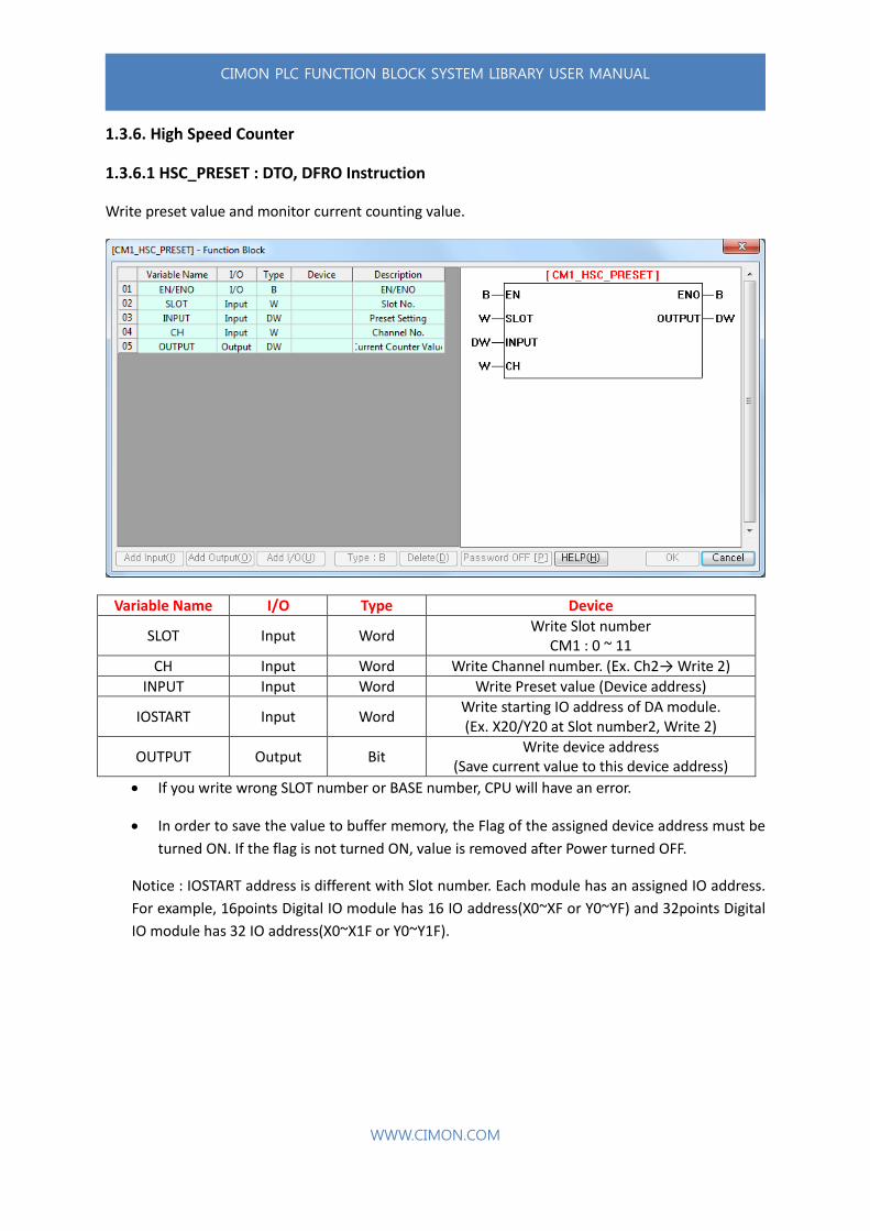
1.3.6.1 HSC_PRESET : DTO, DFRO Instruction
Write preset value and monitor current counting value.
Variable Name I/O Type Device
SLOT Input Word Write Slot number
CM1 : 0 ~ 11
CH Input Word Write Channel number. (Ex. Ch2→ Write 2)
INPUT Input Word Write Preset value (Device address)
IOSTART Input Word Write starting IO address of DA module. (Ex. X20/Y20 at Slot number2, Write 2)
OUTPUT Output Bit Write device address
(Save current value to this device address)
If you write wrong SLOT number or BASE number, CPU will have an error.
In order to save the value to buffer memory, the Flag of the assigned device address must be
turned ON. If the flag is not turned ON, value is removed after Power turned OFF.
Notice : IOSTART address is different with Slot number. Each module has an assigned IO address.
For example, 16points Digital IO module has 16 IO address(X0~XF or Y0~YF) and 32points Digital
IO module has 32 IO address(X0~X1F or Y0~Y1F).
CIMON PLC FUNCTION BLOCK SYSTEM LIBRARY USER MANUAL
WWW.CIMON.COM
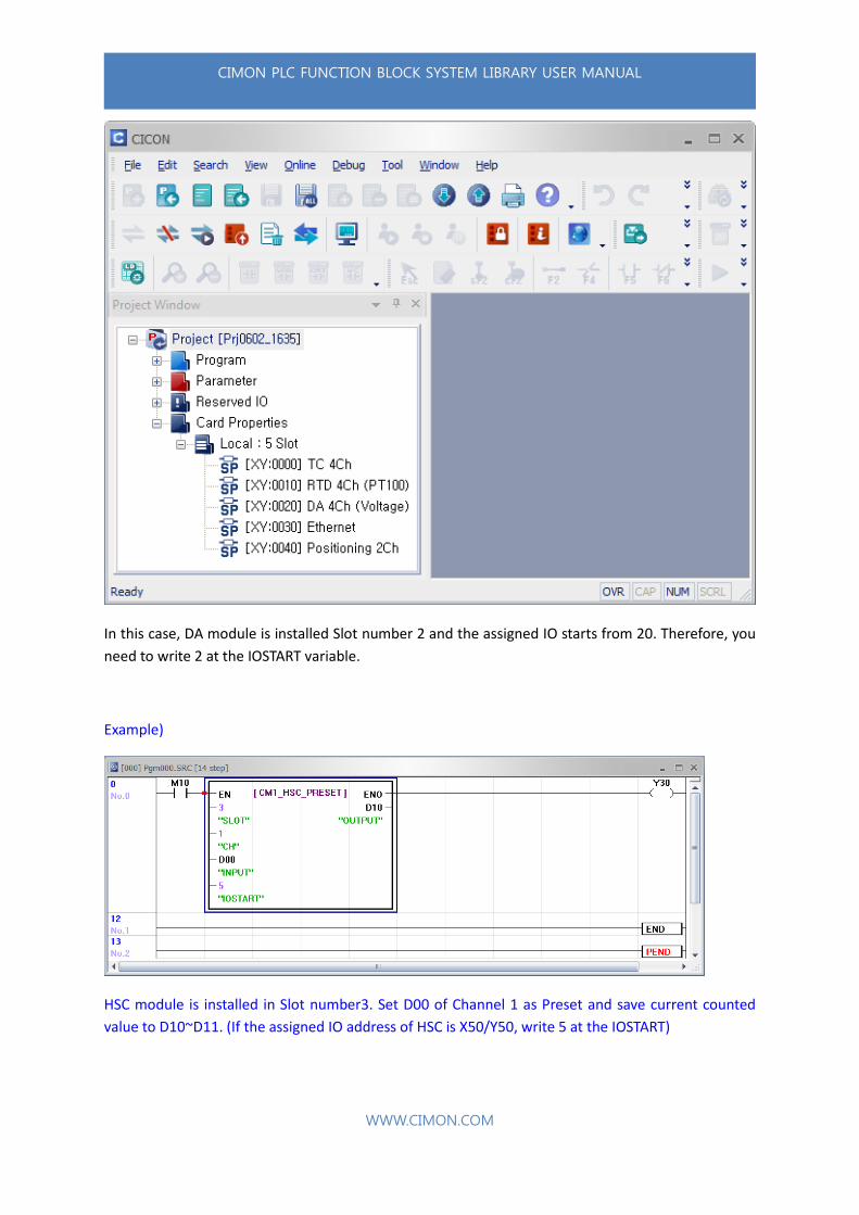
In this case, DA module is installed Slot number 2 and the assigned IO starts from 20. Therefore, you
need to write 2 at the IOSTART variable.
Example)
HSC module is installed in Slot number3. Set D00 of Channel 1 as Preset and save current counted
value to D10~D11. (If the assigned IO address of HSC is X50/Y50, write 5 at the IOSTART)
CIMON PLC FUNCTION BLOCK SYSTEM LIBRARY USER MANUAL
WWW.CIMON.COM
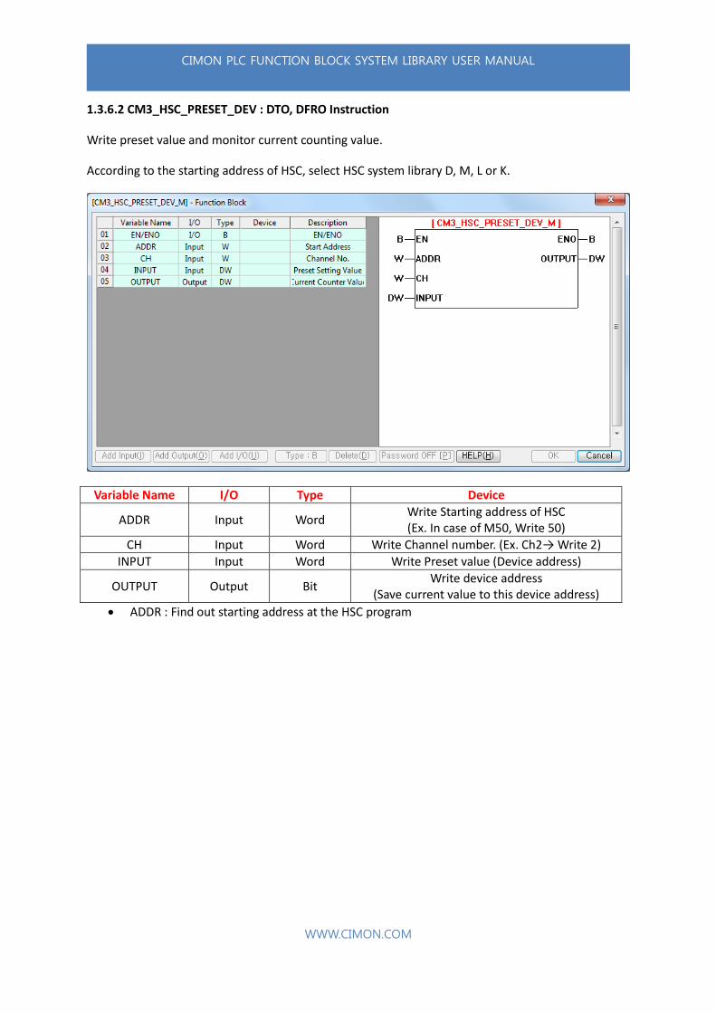
1.3.6.2 CM3_HSC_PRESET_DEV : DTO, DFRO Instruction
Write preset value and monitor current counting value.
According to the starting address of HSC, select HSC system library D, M, L or K.
Variable Name I/O Type Device
ADDR Input Word Write Starting address of HSC (Ex. In case of M50, Write 50)
CH Input Word Write Channel number. (Ex. Ch2→ Write 2)
INPUT Input Word Write Preset value (Device address)
OUTPUT Output Bit Write device address
(Save current value to this device address)
ADDR : Find out starting address at the HSC program
CIMON PLC FUNCTION BLOCK SYSTEM LIBRARY USER MANUAL
WWW.CIMON.COM
• System Library type
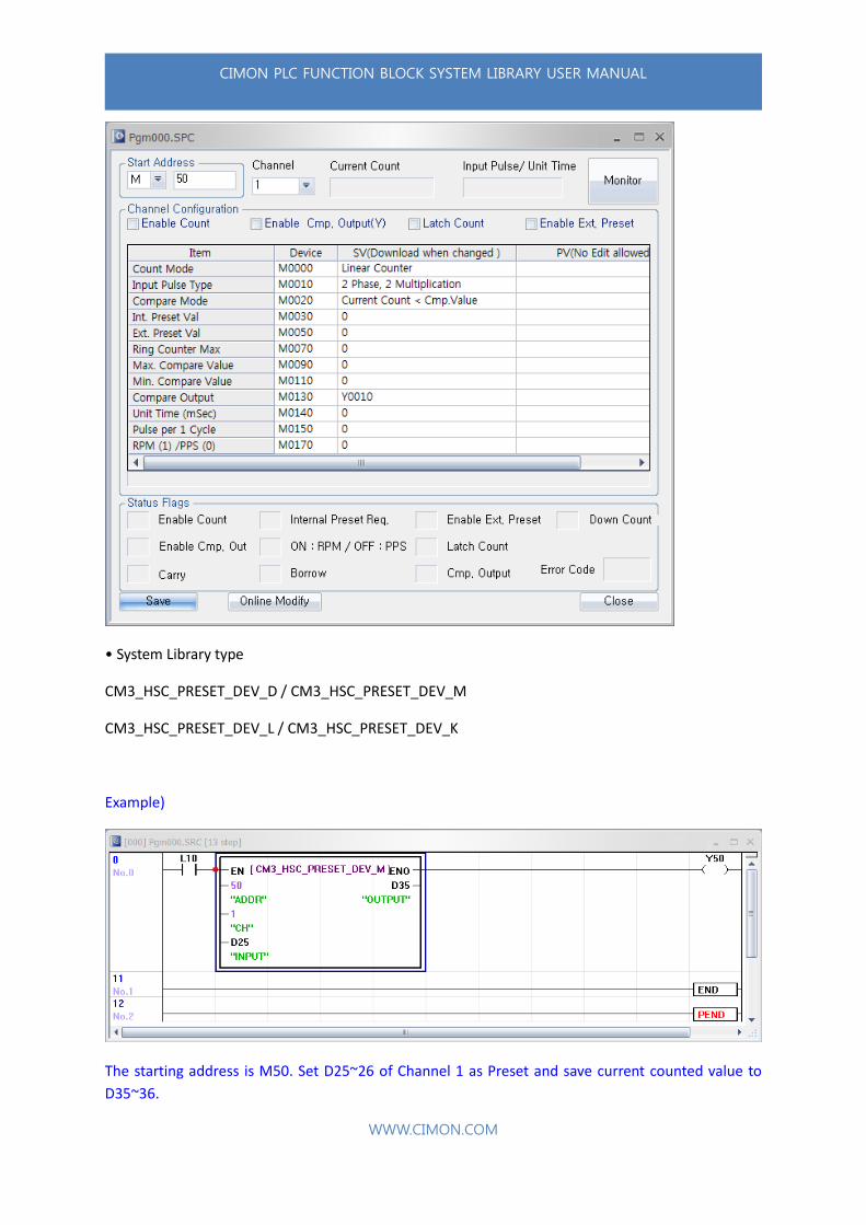
CM3_HSC_PRESET_DEV_D / CM3_HSC_PRESET_DEV_M
CM3_HSC_PRESET_DEV_L / CM3_HSC_PRESET_DEV_K
Example)
The starting address is M50. Set D25~26 of Channel 1 as Preset and save current counted value to
D35~36.
CIMON PLC FUNCTION BLOCK SYSTEM LIBRARY USER MANUAL
WWW.CIMON.COM
1.3.7. FB Instruction
• Instruction system library list
Group CPU Library name Instruction Description
Instruction -
FB_FROM FROM Read buffer memory of Special module
FB_SCL SCL Scale
FB_DATEWR DATEWR Set PLC Time
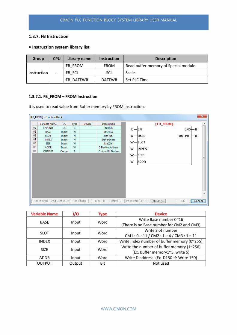
1.3.7.1. FB_FROM – FROM Instruction
It is used to read value from Buffer memory by FROM instruction.
Variable Name I/O Type Device
BASE Input Word Write Base number 0~16
(There is no Base number for CM2 and CM3)
SLOT Input Word Write Slot number
CM1 : 0 ~ 11 / CM2 : 1 ~ 4 / CM3 : 1 ~ 11
INDEX Input Word Write Index number of buffer memory (0~255)
SIZE Input Word Write the number of buffer memory (1~256)
(Ex. Buffer memory1~5, write 5)
ADDR Input Word Write D address. (Ex. D150 → Write 150)
OUTPUT Output Bit Not used

CIMON PLC FUNCTION BLOCK SYSTEM LIBRARY USER MANUAL
WWW.CIMON.COM
Example)
You can read one data from Buffer memory 26 at Slot number3 in Local Base and save it to D00.
1.3.7.2. FB_SCL – SCL Instruction (Analog input scaling)
It converts input value to scale value. If scale does not work, ENO will be reset.
Variable Name I/O Type Device
SOURCE_DATA Input Word Write original value
SOURCE_MIN Input Word Write original minimum value
SOURCE_MAX Input Word Write original maximum value
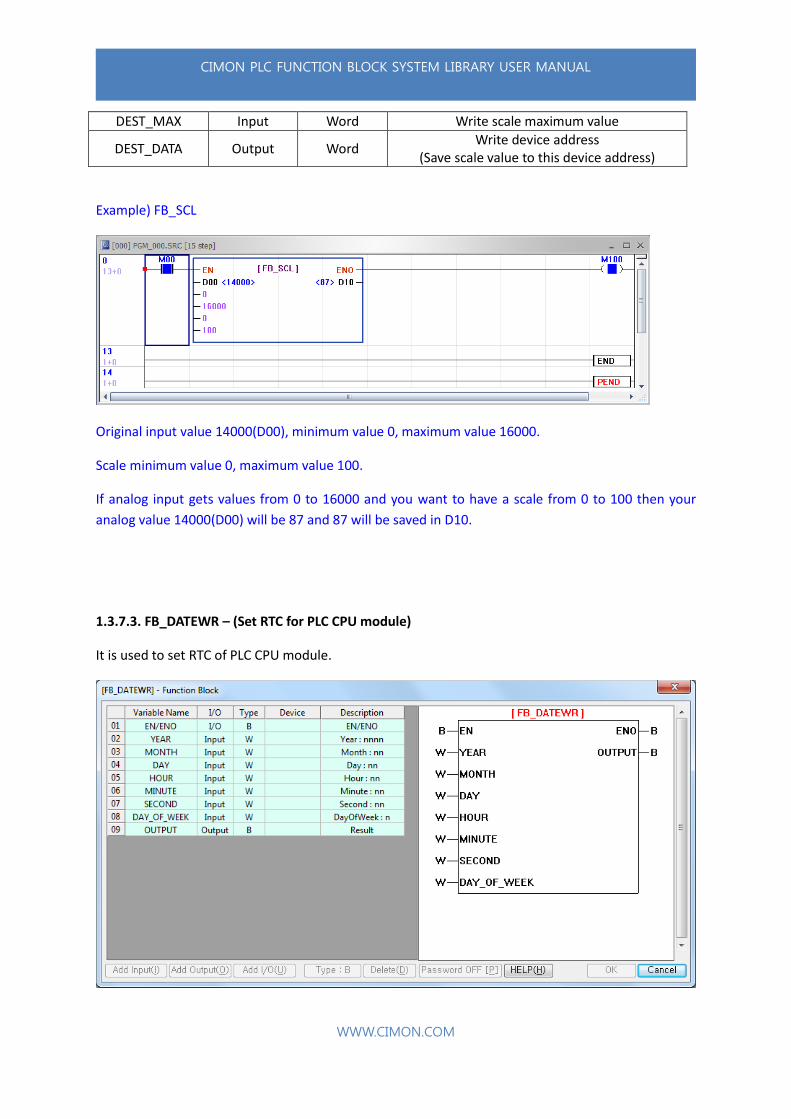
DEST_MIN Input Word Write scale minimum value
CIMON PLC FUNCTION BLOCK SYSTEM LIBRARY USER MANUAL
WWW.CIMON.COM
DEST_MAX Input Word Write scale maximum value
DEST_DATA Output Word Write device address
(Save scale value to this device address)
Example) FB_SCL
Original input value 14000(D00), minimum value 0, maximum value 16000.
Scale minimum value 0, maximum value 100.
If analog input gets values from 0 to 16000 and you want to have a scale from 0 to 100 then your
analog value 14000(D00) will be 87 and 87 will be saved in D10.
1.3.7.3. FB_DATEWR – (Set RTC for PLC CPU module)
It is used to set RTC of PLC CPU module.

CIMON PLC FUNCTION BLOCK SYSTEM LIBRARY USER MANUAL
WWW.CIMON.COM
Variable Name I/O Type Device
YEAR Input Word Write year (2000~2099)
MONTH Input Word Write month (1~12)
DAY Input Word Write date (1~31)
HOUR Input Word Write hour (0~23)
MINUTE Input Word Write minute (0~59)
SECOND Input Word Write second (0~59)
DAY_OF_WEEK Input Word Write day (0~6)
(0:Sunday~6:Saturday)
OUTPUT Output Bit If RTC works, it will be turned ON
• Day of Week : Sunday = 0 / Monday = 1 / Tuesday = 2 / Wednesday = 3 / Thursday = 4 /
Friday = 5 / Saturday = 6
• If EN is not OFF, RTC runs over and over and this will put CPU performance down. Therefore, after
using Function Block, turn EN Off or use (Positive transition-Sensing Contact) for this
function block.
Example) FB_DATEWR (Set RTC for PLC CPU module)
Date: August 15, 2015. Time: 8 : 32 : 00 (Saturday)
When it works, M20 bit will be turned ON and then M00 will be cleared.