cim-7xxx series four stacker card issuing machine for ... revb.pdf · 1.5 “c15” : it is to...
TRANSCRIPT
Doc No CIM-7XXX SPECIFICATION
REV PAGE DATE
B 1 OF 57 2008. 09. 26
©Copyright KYTronics Corp., Ltd.
CIM-7XXX Series Four Stacker Card Issuing Machine
for Magnetic, IC, RF Card
KYTronics Corp.,Ltd 3rd Floor, A-Dong, Twin Town-Bldg, 703-2. Gojan-Dong, AnSan-City, Kyung Ki-Do, Korea(ZIP:425-906) Tel : 82 – 31 – 485 – 9480 Fax : 82 - 31 – 485 – 9488 E-mail : [email protected] http://www. kytronics.co.kr
Doc No CIM-7XXX SPECIFICATION
REV PAGE DATE
B 2 OF 57 2008. 09. 26
©Copyright KYTronics Corp., Ltd.
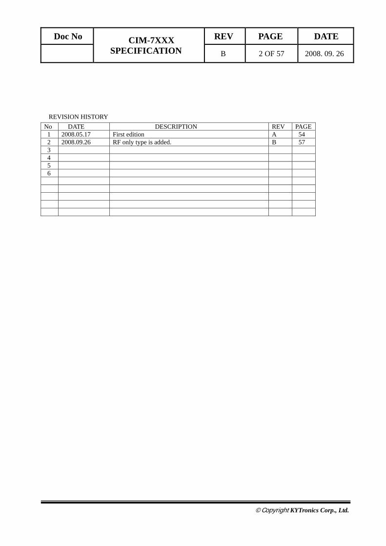
REVISION HISTORY No DATE DESCRIPTION REV PAGE 1 2008.05.17 First edition A 54 2 2008.09.26 RF only type is added. B 57 3 4
5 6
Doc No CIM-7XXX SPECIFICATION
REV PAGE DATE
B 3 OF 57 2008. 09. 26
©Copyright KYTronics Corp., Ltd.
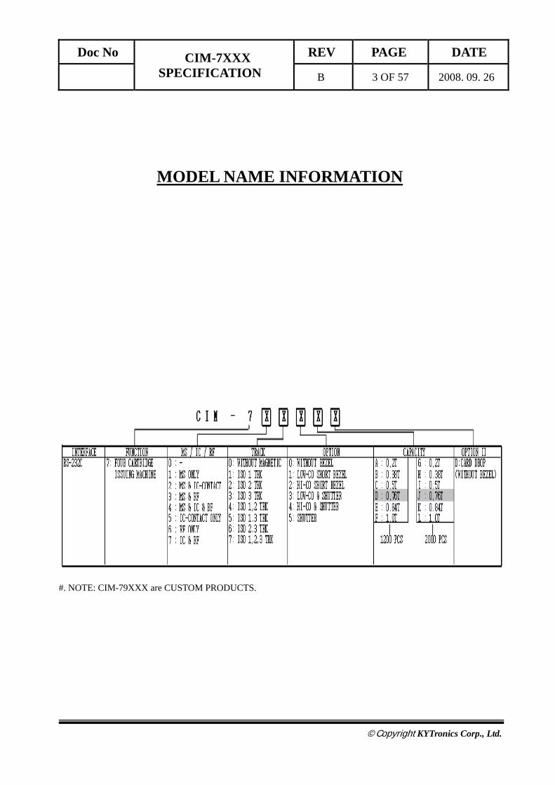
MODEL NAME INFORMATION
#. NOTE: CIM-79XXX are CUSTOM PRODUCTS.

Doc No CIM-7XXX SPECIFICATION
REV PAGE DATE
B 4 OF 57 2008. 09. 26
©Copyright KYTronics Corp., Ltd.
C O N T E N T S
Overview -------------------------------------- 5
System Block Diagram --------------------- 6
Specification ---------------------------------- 8
Magnetic Card Process --------------------- 10
IC Card Process ------------------------------ 11
RF Card Process ------------------------------ 12
Communication Interface ------------------ 13
Technical Drawing --------------------------- 19
Command Detail ----------------------------- 20
Error Detail ----------------------------------- 49
Precautions ---------------------------------- 55

Doc No CIM-7XXX SPECIFICATION
REV PAGE DATE
B 5 OF 57 2008. 09. 26
©Copyright KYTronics Corp., Ltd.
OVERVIEW
CIM7XXX Series is a set of card issuing machine for the magnetic, IC, and RF card in conjunction with the
KYT2600 and KYT3000 series.
KYT-4XXX Series is designed to provide 2,000 pcs cards capacity and 4 different card loading with 4 Stacker
Card Dispenser.
This model can be used for magnetic card conforming to the ISO7816-2 standard and most of the IC cards conforming
with the ISO7816-4 T=0,T=1. Additionally, this model also can be used for the RF card conforming to the MIFARE.
This model simplified the command for magnetic card, minimize the delay time occurs in the communication data
processing, and improved the speed due to function to issue the all tracks at a time.
This model has the following advantages:
1) Remove the latency due to the user-based card exchange, by loading 1,000 PCS(0.76 mm card) at a time.
2) Use the different type of card using four cartridge.
As an automatic issuing machine, this model can be used in issuing most types of credit card and debit card in
financial area.
Doc No CIM-7XXX SPECIFICATION
REV PAGE DATE
B 6 OF 57 2008. 09. 26
©Copyright KYTronics Corp., Ltd.
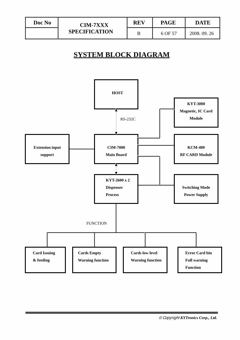
SYSTEM BLOCK DIAGRAM
Extension input
support
HOST
CIM-7000
Main Board
FUNCTION
RS-232C
KYT-2600 x 2
Dispenser
Process
Switching Mode
Power Supply
Error Card bin
Full warning
Function
Cards Empty
Warning function
KCM-400
RF CARD Module
Cards low level
Warning function
Card Issuing
& feeding
KYT-3000
Magnetic, IC Card
Module

Doc No CIM-7XXX SPECIFICATION
REV PAGE DATE
B 7 OF 57 2008. 09. 26
©Copyright KYTronics Corp., Ltd.
♦ RS – 232 Connection
CASE 1) Part Number : RED-9S-LNA(HIROSE) Pin No INDEX Remark 2 RXD Receive 3 TXD Transmit 5 S.G Signal Ground
♦ RS422 Connection
CASE 1) Part Number : RED-9S-LNA(HIROSE) Pin No INDEX Remark 1 TX+ 4 RX+ 6 TX- 8 RX-
TXD
HOST RXD
S.G
TXD
RXD KYT6xxx
S.G
TX+
RX+
HOST TX-
RX-
TX+
RX+
TX- KYT7xxx
RX-
Doc No CIM-7XXX SPECIFICATION
REV PAGE DATE
B 8 OF 57 2008. 09. 26
©Copyright KYTronics Corp., Ltd.
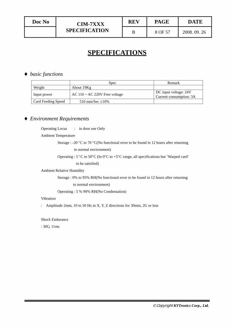
SPECIFICATIONS
♦ basic functions
Spec Remark Weight About 19Kg
Input power AC 110 ~ AC 220V Free voltage DC input voltage: 24V Current consumption: 3A
Card Feeding Speed 510 mm/Sec ±10%
♦ Environment Requirements
Operating Locus : in door use Only
Ambient Temperature
Storage : -20 °C to 70 °C(No functional error to be found in 12 hours after returning
to normal environment)
Operating : 5 °C to 50°C (In 0°C to +5°C range, all specifications but ‘Warped card’
to be satisfied)
Ambient Relative Humidity
Storage : 0% to 95% RH(No functional error to be found in 12 hours after returning
to normal environment)
Operating : 5 % 90% RH(No Condensation)
Vibration
: Amplitude 2mm, 10 to 50 Hz in X, Y, Z directions for 30min, 2G or less
Shock Endurance
: 30G, 11ms
Doc No CIM-7XXX SPECIFICATION
REV PAGE DATE
B 9 OF 57 2008. 09. 26
©Copyright KYTronics Corp., Ltd.
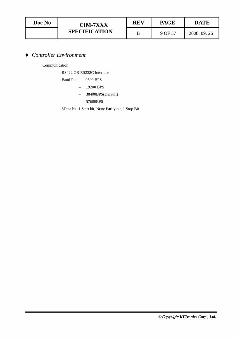
♦ Controller Environment
Communication
: RS422 OR RS232C Interface
: Baud Rate – 9600 BPS
– 19200 BPS
– 38400BPS(Default)
– 57600BPS
: 8Data bit, 1 Start bit, None Parity bit, 1 Stop Bit
Doc No CIM-7XXX SPECIFICATION
REV PAGE DATE
B 10 OF 57 2008. 09. 26
©Copyright KYTronics Corp., Ltd.
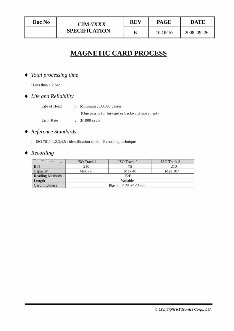
MAGNETIC CARD PROCESS
♦ Total processing time
: Less than 1.2 Sec
♦ Life and Reliability
Life of Head : Minimum 1,00,000 passes
(One pass is for forward or backward movement)
Error Rate : 3/1000 cycle
♦ Reference Standards
: ISO 7811-1,2,3,4,5 : identification cards – Recording technique
♦ Recording
ISO Track 1 ISO Track 2 ISO Track 3 BPI 210 75 210 Capacity Max 79 Max 40 Max 107 Reading Methods F2F Length Variable Card thickness Plastic : 0.76 ±0.08mm
Doc No CIM-7XXX SPECIFICATION
REV PAGE DATE
B 11 OF 57 2008. 09. 26
©Copyright KYTronics Corp., Ltd.
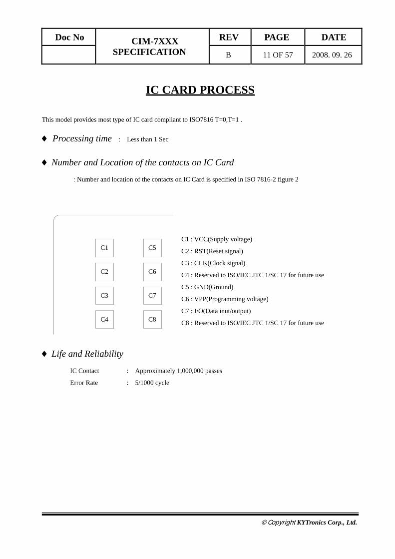
IC CARD PROCESS
This model provides most type of IC card compliant to ISO7816 T=0,T=1 .
♦ Processing time : Less than 1 Sec
♦ Number and Location of the contacts on IC Card
: Number and location of the contacts on IC Card is specified in ISO 7816-2 figure 2
C1 : VCC(Supply voltage)
C2 : RST(Reset signal)
C3 : CLK(Clock signal)
C4 : Reserved to ISO/IEC JTC 1/SC 17 for future use
C5 : GND(Ground)
C6 : VPP(Programming voltage)
C7 : I/O(Data inut/output)
C8 : Reserved to ISO/IEC JTC 1/SC 17 for future use
♦ Life and Reliability
IC Contact : Approximately 1,000,000 passes
Error Rate : 5/1000 cycle
C1
C2
C3
C4
C5
C6
C7
C8
Doc No CIM-7XXX SPECIFICATION
REV PAGE DATE
B 12 OF 57 2008. 09. 26
©Copyright KYTronics Corp., Ltd.
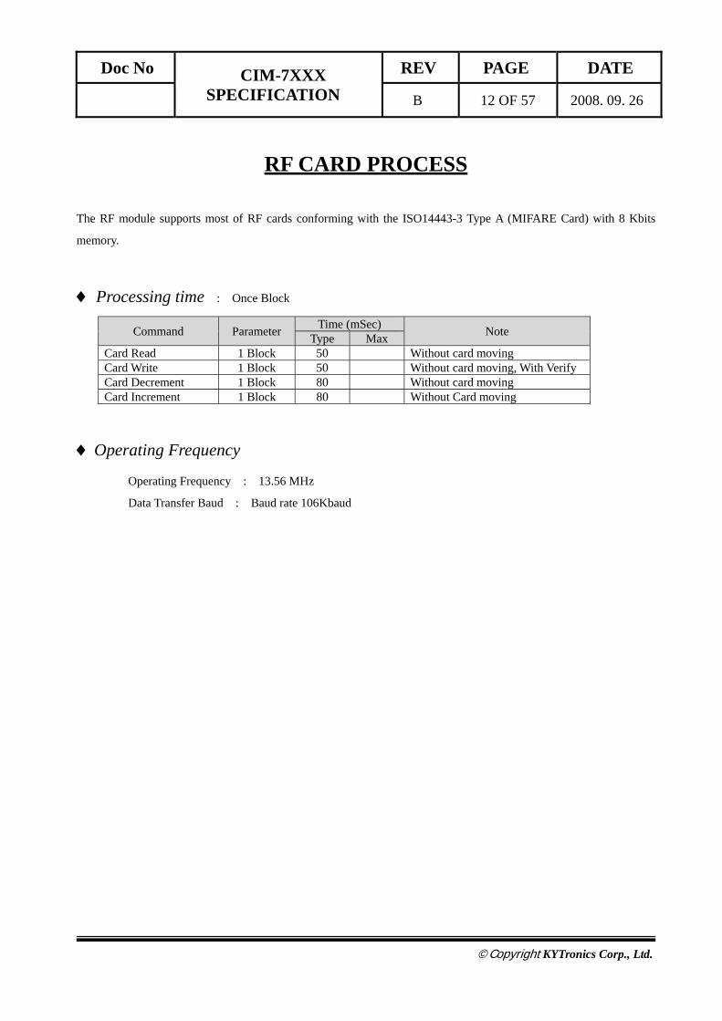
RF CARD PROCESS
The RF module supports most of RF cards conforming with the ISO14443-3 Type A (MIFARE Card) with 8 Kbits
memory.
♦ Processing time : Once Block
Command Parameter Time (mSec) Note Type Max Card Read 1 Block 50 Without card moving Card Write 1 Block 50 Without card moving, With Verify Card Decrement 1 Block 80 Without card moving Card Increment 1 Block 80 Without Card moving
♦ Operating Frequency
Operating Frequency : 13.56 MHz
Data Transfer Baud : Baud rate 106Kbaud

Doc No CIM-7XXX SPECIFICATION
REV PAGE DATE
B 13 OF 57 2008. 09. 26
©Copyright KYTronics Corp., Ltd.
COMMUNICATION INTERFACE
♦ Communication Method Asynchronous, Half duplex.
Baud Rate : 9600 – 57600Bps , Default : 38400Bps
Start Bit : 1Bit
Data Length : 8Bit
Parity : None
Stop Bit : 1Bit
♦ Communication Protocol Format 1 Command Frame Format.
SOH Null Length STX CMD DATA ETX BCC 1 byte 1 byte 2 byte 1 byte 3 byte N byte 1 byte 1 byte
(N byte: Variable length)
2 Positive Response Frame Format SOH Null Length STX CMD GOOD 0x01 DATA ETX BCC 1 byte 1 byte 2 byte 1 byte 3 byte 2 byte 1 byte N byte 1 byte 1 byte
3 Negative Response Frame Format SOH Null Length STX CMD E-Code 0x00 ETX BCC 1 byte 1 byte 2 byte 1 byte 3 byte 2 byte 1 byte 1 byte 1 byte
4 BCC (Check Sum) SOH Null Length STX CMD DATA ETX BCC
Command Frame BCC = Null ^ Length ^ STX ^ CMD ^ DATA ^ ETX.
Positive Response BCC = Null ^ Length ^ STX ^ CMD ^ GOOD ^ 0x01 ^ DATA ^ ETX.
Negative Response BCC = Null ^ Length ^ STX ^ CMD ^ E-Code ^ ETX.
BCC (Check Sum)
Doc No CIM-7XXX SPECIFICATION
REV PAGE DATE
B 14 OF 57 2008. 09. 26
©Copyright KYTronics Corp., Ltd.
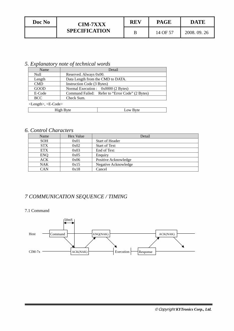
5. Explanatory note of technical words Name Detail
Null Reserved. Always 0x00. Length Data Length from the CMD to DATA. CMD Instruction Code (3 Bytes) GOOD Normal Execution : 0x0000 (2 Bytes) E-Code Command Failed: Refer to “Error Code” (2 Bytes) BCC Check Sum.
<Length>, <E-Code> High Byte Low Byte
6. Control Characters Name Hex Value Detail SOH 0x01 Start of Header STX 0x02 Start of Text ETX 0x03 End of Text ENQ 0x05 Enquiry ACK 0x06 Positive Acknowledge NAK 0x15 Negative Acknowledge CAN 0x18 Cancel
7 COMMUNICATION SEQUENCE / TIMING
7.1 Command
Command
Response
ACK(NAK) Host
CIM-7x ACK(NAK)
ENQ(NAK)
50mS
Execution

Doc No CIM-7XXX SPECIFICATION
REV PAGE DATE
B 15 OF 57 2008. 09. 26
©Copyright KYTronics Corp., Ltd.
7.2 Inquiry
7.3 Sequence
7.3.1 General
Response
Host
CIM-7x Execution
ENQ ACK
ACK
Command
ENQ Host
CIM-7x
ENQ ENQ
ENQ ENQ ENQ
ENQ Host
CIM-7x
ENQ ENQ
ENQ ENQ ENQ
50mS
Doc No CIM-7XXX SPECIFICATION
REV PAGE DATE
B 16 OF 57 2008. 09. 26
©Copyright KYTronics Corp., Ltd.
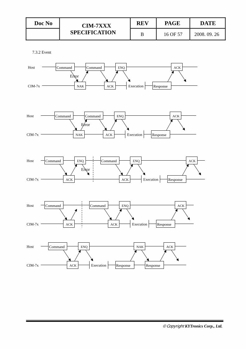
7.3.2 Event
Command
Response
Host
CIM-7x Execution
ENQ ACK
ACK
Command
NAK
Error
Command
Response
Host
CIM-7x Execution
ENQ ACK
ACK
Command
NAK
Error
Command
Response
Host
CIM-7x Execution
ENQ ACK
ACK
Command
ACK
Error
ENQ
Command
Response
Host
CIM-7x Execution
ENQ ACK
ACK
Command
ACK
Response
Host
CIM-7x Execution
ENQ NAK
ACK
Command
Response
ACK

Doc No CIM-7XXX SPECIFICATION
REV PAGE DATE
B 17 OF 57 2008. 09. 26
©Copyright KYTronics Corp., Ltd.
Response
Host
CIM-7x Execution
ENQ NAK
ACK
Command
Response
ACK
Response
NAK
Response
Host
CIM-7x Execution
ENQ NAK
ACK
Command
Response
NAK
Response
NAK
Response
Host
CIM-7x Execution
ENQ
ACK
Command
Response Response
Error Error Error
Response
Host
CIM-7x Execution
ENQ
ACK
Command
Response
Error
ACK
Command1
Response
Host
CIM-7x Execution
ENQ ACK
Cancel
Command2
ACK
Error
Execution
Rejection
Command1: Consecutive Execution of
Doc No CIM-7XXX SPECIFICATION
REV PAGE DATE
B 18 OF 57 2008. 09. 26
©Copyright KYTronics Corp., Ltd.
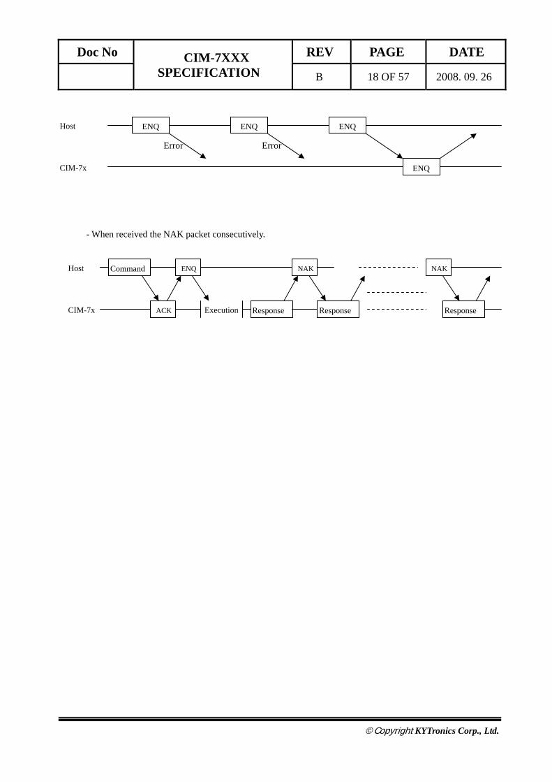
- When received the NAK packet consecutively.
ENQ Host
CIM-7x
ENQ ENQ
ENQ
Error Error
Response
Host
CIM-7x Execution
ENQ NAK
ACK
Command
Response
NAK
Response
Doc No CIM-7XXX SPECIFICATION
REV PAGE DATE
B 19 OF 57 2008. 09. 26
©Copyright KYTronics Corp., Ltd.
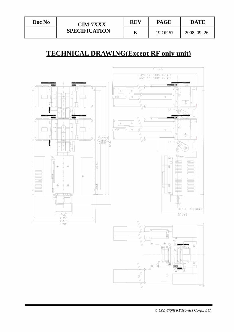
TECHNICAL DRAWING(Except RF only unit)

Doc No CIM-7XXX SPECIFICATION
REV PAGE DATE
B 20 OF 57 2008. 09. 26
©Copyright KYTronics Corp., Ltd.
TECHNICAL DRAWING(CIM-76XX)

Doc No CIM-7XXX SPECIFICATION
REV PAGE DATE
B 21 OF 57 2008. 09. 26
©Copyright KYTronics Corp., Ltd.
CUSTOM PRODUCT #1 DRAWING (CIM-7902) - Without main control board, SMPS, RF module and MS/IC encoder module.

Doc No CIM-7XXX SPECIFICATION
REV PAGE DATE
B 22 OF 57 2008. 09. 26
©Copyright KYTronics Corp., Ltd.
COMMAND DETAIL
♦ Command List Item Cm0 Cm1 Cm2 Detail Note
COMMON
STATUS
‘C’ ‘1’ ‘1’ Get Model ‘C’ ‘1’ ‘2’ Get Firmware Version ‘C’ ‘1’ ‘3’ Get Stacker ‘C’ ‘1’ ‘4’ Get Status List ‘C’ ‘1’ ‘5’ Get Error List ‘C’ ‘1’ ‘6’ Get Card Position
SETTING_1
‘C’ ‘2’ ‘1’ Set RTC IC Check ‘C’ ‘2’ ‘4’ Set Retry Count Check ‘C’ ‘2’ ‘5’ Set Buzz On/Off Cont. Check ‘C’ ‘2’ ‘6’ Set Baud Rate Check
MOVE
‘C’ ‘3’ ‘1’ Card Move From Stacker ‘C’ ‘3’ ‘2’ Card Move To … ‘C’ ‘3’ ‘4’ Card Capture Backward‘C’ ‘3’ ‘6’ Card Eject (Drop Mode) Forward ‘C’ ‘3’ ‘7’ Card Eject (Hold Mode) Forward
SETTING_2 C ‘4’ ‘2’ Software Reset
MAGNETIC CARD
MAGNETICREAD / WRITE
‘M’ ‘3’ ‘1’ Magnetic Card Read ‘M’ ‘3’ ‘3’ Magnetic Card Write Verify** ‘M’ ‘3’ ‘4’ Magnetic Card Write From Stacker Verify** ‘M’ ‘3’ ‘5’ Magnetic Card All Track Read
CLEANING ‘M’ ‘5’ ‘1’ MSRW Header Cleaning
IC CARD IC CONTROL
‘I’ ‘2’ ‘1’ IC Card Reset ‘I’ ‘2’ ‘2’ IC Card Direct Control
RF CARD
RF READ / WRITE
‘R’ ‘3’ ‘1’ RF Card Read in Block Range ‘R’ ‘3’ ‘2’ RF Card Write in Block Range ‘R’ ‘3’ ‘6’ Read RF card data in sector range ‘R’ ‘3’ ‘7’ Write RF card data in sector range
BALANCE ‘R’ ‘4’ ‘1’ Increases balance in RF card ‘R’ ‘4’ ‘2’ Decreases balance in RF card
SECRET KEY CHANGE
‘R’ ‘5’ ‘1’ Change ‘Secret Key’ to other Key ‘R’ ‘5’ ‘2’ Change ‘Secret Key’ to all the same Key value ‘R’ ‘5’ ‘3’ Select ‘Secret Key Index’ ‘R’ ‘5’ ‘4’ Change RF Card ‘Secret Key’ to other key
RF DETECT ‘R’ ‘6’ ‘1’ Check RF card in antenna area

Doc No CIM-7XXX SPECIFICATION
REV PAGE DATE
B 23 OF 57 2008. 09. 26
©Copyright KYTronics Corp., Ltd.
♦ Common
These are the command set that all the CIM-7000 Series use. These commands include the terminal setting and
the card movement related commands.
The ‘STATUS’ commands provide the function to check the current terminal status and the errors occurred during the
command execution.
The ‘SETTING’ commands consist of commands for setting the terminal and these commands is easy to use
because the same command can use for both setting and checking the terminal.
The ‘MOVE’ commands consist of commands used commonly like the card eject and capture command.
Commands Set: Item Cm0 Cm1 Cm2 Detail Note
COMMON
STATUS
‘C’ ‘1’ ‘1’ Get Model ‘C’ ‘1’ ‘2’ Get Firmware Version ‘C’ ‘1’ ‘3’ Get Stacker ‘C’ ‘1’ ‘4’ Get Status List ‘C’ ‘1’ ‘5’ Get Error List ‘C’ ‘1’ ‘6’ Get Card Position
SETTING_1
‘C’ ‘2’ ‘1’ Set RTC IC Check ‘C’ ‘2’ ‘4’ Set Retry Count Check ‘C’ ‘2’ ‘5’ Set Buzz On/Off Cont. Check ‘C’ ‘2’ ‘6’ Set Baud Rate Check
MOVE
‘C’ ‘3’ ‘1’ Card Move From Stacker ‘C’ ‘3’ ‘2’ Card Move To … ‘C’ ‘3’ ‘4’ Card Capture Backward‘C’ ‘3’ ‘6’ Card Eject (Drop Mode) Forward ‘C’ ‘3’ ‘7’ Card Eject (Hold Mode) Forward
SETTING_2 C ‘4’ ‘2’ Software Reset

Doc No CIM-7XXX SPECIFICATION
REV PAGE DATE
B 24 OF 57 2008. 09. 26
©Copyright KYTronics Corp., Ltd.
1 STATUS / SETTING
1.1 “C11” : It is to check out Model number of CIM-7000. ☞ Command Format
SOH Null Length STX “C11” ETX Bcc ☞ Positive Response Format
SOH Null Length STX “C11” GOOD 0x01 DATA ETX Bcc ☞ Negative Response Format
SOH Null Length STX “C11” E-Code 0x00 ETX Bcc ☞ Response Data Structure
Model No 30 Byte (ASCII)
1.2 “C12” : It is to check out Firmware Version of CIM-7000 ☞ Command Format
SOH Null Length STX “C12” ETX Bcc ☞ Positive Response Format
SOH Null Length STX “C12” GOOD 0x01 DATA ETX Bcc ☞ Negative Response Format
SOH Null Length STX “C12” E-Code 0x00 ETX Bcc ☞ Response Data Structure
VERSION 30 Byte (ASCII)
1.3 “C13” : It is check out status of Stacker of CIM-7000 ☞ Command Format
SOH Null Length STX “C13” ETX Bcc ☞ Positive Response Format
SOH Null Length STX “C13” GOOD 0x01 DATA ETX Bcc ☞ Negative Response Format
SOH Null Length STX “C13” E-Code 0x00 ETX Bcc ☞ Response Data Structure
Stacker 1 Stacker 2 Stacker 3 Stacker 4 1Byte (Hex) 1Byte (Hex) 1Byte (Hex) 1Byte (Hex)

Doc No CIM-7XXX SPECIFICATION
REV PAGE DATE
B 25 OF 57 2008. 09. 26
©Copyright KYTronics Corp., Ltd.
☞ Data Variable
<Stacker1> <Stacker2> Code Status Code Status 0x01 Stacker #1 Good 0x01 Stacker #2 Good 0x02 Stacker #1 Warning 0x02 Stacker #2 Warning 0x03 Stacker #1 Empty 0x03 Stacker #2 Empty
<Stacker3> <Stacker4> Code Status Code Status 0x01 Stacker #1 Good 0x01 Stacker #2 Good 0x02 Stacker #1 Warning 0x02 Stacker #2 Warning 0x03 Stacker #1 Empty 0x03 Stacker #2 Empty
☞ Note Stacker Status Detail
‘Stacker Good’ Too many cards loading 1) ‘Stacker Warning’ Too few cards loading 1) ‘Stacker Empty’ No cards in stacker
1) The stacker status is detected by the sensor behind the stacker. The number of cards can be changed.
1.4 “C14” : It is to check out current Status of CIM-7000 ☞ Command Format
SOH Null Length STX “C14” ETX Bcc ☞ Positive Response Format
SOH Null HL Length “C14” GOOD 0x01 DATA ETX Bcc ☞ Negative Response Format
SOH Null Length STX “C14” E-Code 0x00 ETX Bcc ☞ Response Data Structure
Error Code (1) --- Error Code (N)
High Byte Low Byte 2Byte
☞ Note
You can identify the stacker status, motor status, card status (jamming) and communication status through
the Error Code in the response data structure.

Doc No CIM-7XXX SPECIFICATION
REV PAGE DATE
B 26 OF 57 2008. 09. 26
©Copyright KYTronics Corp., Ltd.
1.5 “C15” : It is to check out error while Command is being executed. ☞ Command Format
SOH Null Length STX “C15” ETX Bcc ☞ Positive Response Format
SOH Null Length STX “C15” GOOD 0x01 DATA ETX Bcc ☞ Negative Response Format
SOH Null Length STX “C15” E-Code 0x00 ETX Bcc ☞ Response Data Structure
Error Time (1) Error Code (1) --- Error Time (N) Error Code (N)7Byte (BCD) 2Byte (Hex) --- 7Byte (BCD) 2Byte (Hex)
High Year Low Year Month Day Hour Minute Second
1Byte 1Byte 1Byte 1Byte 1Byte 1Byte 1Byte
High Byte Low Byte
1Byte 1Byte ☞ Note
This command is only correspond to the error occurred during command execution. The time when an error
is occurred is represented to the BCD, while the error code to the HEX.
1.5 “C16” : It is to check out current card position of CIM-7000 ☞ Command Format
SOH Null Length STX “C16” ETX Bcc ☞ Positive Response Format
SOH Null Length STX “C16” GOOD 0x01 DATA ETX Bcc ☞ Negative Response Format
SOH Null Length STX “C16” E-Code 0x00 ETX Bcc ☞ Response Data Structure
Card Position 1Byte (Hex)
<Card Position> Refer to next page. Number Code Sensor
1 0x01 SEN1 2 0x02 SEN2 3 0x04 SEN3 4 0x08 SEN4 5 0x10 SEN5 6 0x20 SEN6 7 0x40 SEN7 8 0x80 SEN8

Doc No CIM-7XXX SPECIFICATION
REV PAGE DATE
B 27 OF 57 2008. 09. 26
©Copyright KYTronics Corp., Ltd.
SEN 8 SEN 7 SEN 6 SEN 5 SEN 4 SEN 3 SEN 2 SEN 1
STACKER 1
STACKER 2
STACKER 3
STACKER 4
Doc No CIM-7XXX SPECIFICATION
REV PAGE DATE
B 28 OF 57 2008. 09. 26
©Copyright KYTronics Corp., Ltd.
2 SETTING
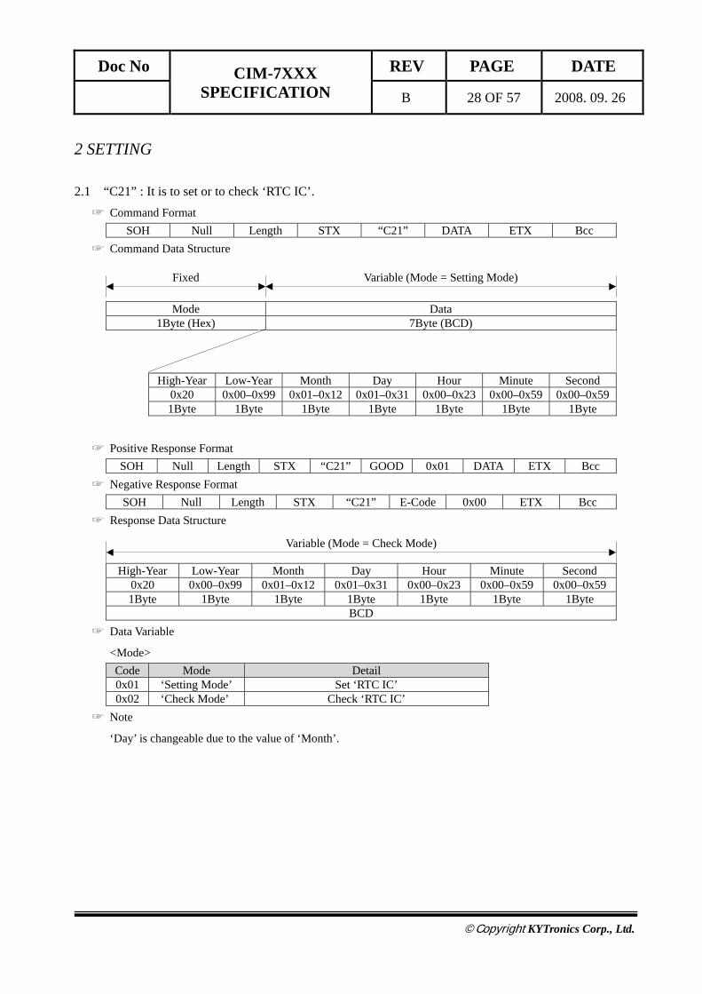
2.1 “C21” : It is to set or to check ‘RTC IC’. ☞ Command Format
SOH Null Length STX “C21” DATA ETX Bcc ☞ Command Data Structure
Mode Data
1Byte (Hex) 7Byte (BCD)
High-Year Low-Year Month Day Hour Minute Second
0x20 0x00–0x99 0x01–0x12 0x01–0x31 0x00–0x23 0x00–0x59 0x00–0x591Byte 1Byte 1Byte 1Byte 1Byte 1Byte 1Byte
☞ Positive Response Format SOH Null Length STX “C21” GOOD 0x01 DATA ETX Bcc
☞ Negative Response Format SOH Null Length STX “C21” E-Code 0x00 ETX Bcc
☞ Response Data Structure
High-Year Low-Year Month Day Hour Minute Second 0x20 0x00–0x99 0x01–0x12 0x01–0x31 0x00–0x23 0x00–0x59 0x00–0x591Byte 1Byte 1Byte 1Byte 1Byte 1Byte 1Byte
BCD ☞ Data Variable
<Mode> Code Mode Detail 0x01 ‘Setting Mode’ Set ‘RTC IC’ 0x02 ‘Check Mode’ Check ‘RTC IC’
☞ Note
‘Day’ is changeable due to the value of ‘Month’.
Fixed Variable (Mode = Setting Mode)
Variable (Mode = Check Mode)
Doc No CIM-7XXX SPECIFICATION
REV PAGE DATE
B 29 OF 57 2008. 09. 26
©Copyright KYTronics Corp., Ltd.
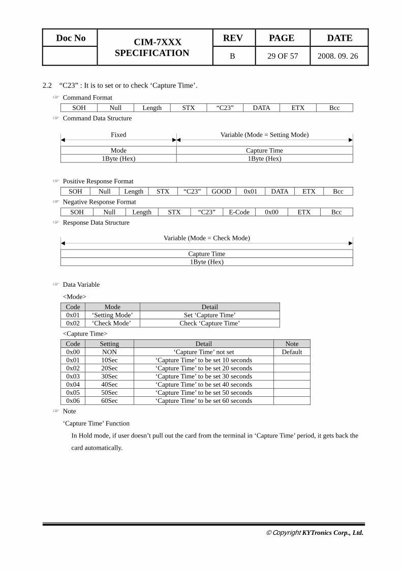
2.2 “C23” : It is to set or to check ‘Capture Time’. ☞ Command Format
SOH Null Length STX “C23” DATA ETX Bcc ☞ Command Data Structure
Mode Capture Time 1Byte (Hex) 1Byte (Hex)
☞ Positive Response Format SOH Null Length STX “C23” GOOD 0x01 DATA ETX Bcc
☞ Negative Response Format SOH Null Length STX “C23” E-Code 0x00 ETX Bcc
☞ Response Data Structure
Capture Time 1Byte (Hex)
☞ Data Variable
<Mode> Code Mode Detail 0x01 ‘Setting Mode’ Set ‘Capture Time’ 0x02 ‘Check Mode’ Check ‘Capture Time’
<Capture Time> Code Setting Detail Note 0x00 NON ‘Capture Time’ not set Default 0x01 10Sec ‘Capture Time’ to be set 10 seconds 0x02 20Sec ‘Capture Time’ to be set 20 seconds 0x03 30Sec ‘Capture Time’ to be set 30 seconds 0x04 40Sec ‘Capture Time’ to be set 40 seconds 0x05 50Sec ‘Capture Time’ to be set 50 seconds 0x06 60Sec ‘Capture Time’ to be set 60 seconds
☞ Note
‘Capture Time’ Function
In Hold mode, if user doesn’t pull out the card from the terminal in ‘Capture Time’ period, it gets back the
card automatically.
Variable (Mode = Setting Mode) Fixed
Variable (Mode = Check Mode)

Doc No CIM-7XXX SPECIFICATION
REV PAGE DATE
B 30 OF 57 2008. 09. 26
©Copyright KYTronics Corp., Ltd.
2.3 “C24” : It is to set or to check ‘Retry Count’. ☞ Command Format
SOH Null Length STX “C24” DATA ETX Bcc ☞ Command Data Structure
Mode Retry Count 1Byte (Hex) 1Byte (Hex)
☞ Positive Response Format SOH Null Length STX “C24” GOOD 0x01 DATA ETX Bcc
☞ Negative Response Format SOH Null Length STX “C24” E-Code 0x00 ETX Bcc
☞ Response Data Structure
Retry Count 1Byte (Hex)
☞ Data Variable
<Mode> Code Mode Detail 0x01 ‘Setting Mode’ Set ‘Retry Count’ 0x02 ‘Check Mode’ Check ‘Retry Count’
<Retry Count> Code Setting Detail Note 0x00 NON Do not retry 0x01 Once Execute the instruction again. 0x02 Twice Retry it twice 0x03 Three times Retry it three times Default
Variable (Mode = Setting Mode) Fixed
Variable (Mode = Check Mode)

Doc No CIM-7XXX SPECIFICATION
REV PAGE DATE
B 31 OF 57 2008. 09. 26
©Copyright KYTronics Corp., Ltd.
2.4 “C25” : It is to set or to check ‘Buzz Control’. ☞ Command Format
SOH Null Length STX “C25” DATA ETX Bcc ☞ Command Data Structure
Mode Buzz Status 1Byte (Hex) 1Byte (Hex)
☞ Positive Response Format SOH Null Length STX “C25” GOOD 0x01 DATA ETX Bcc
☞ Negative Response Format SOH Null Length STX “C25” E-Code 0x00 ETX Bcc
☞ Response Data Structure
Buzz Status 1Byte (Hex)
☞ Data Variable
<Mode> Code Mode Detail 0x01 ‘Setting Mode’ Set ‘Buzz Control’ 0x02 ‘Check Mode’ Check ‘Buzz Control’
<Buzz Status> Code Setting Detail Note 0x01 Buzz Off Buzz Off 0x02 Buzz On Buzz On Default
☞ Note
Variable (Mode = Setting Mode) Fixed
Variable (Mode = Check Mode)
Doc No CIM-7XXX SPECIFICATION
REV PAGE DATE
B 32 OF 57 2008. 09. 26
©Copyright KYTronics Corp., Ltd.
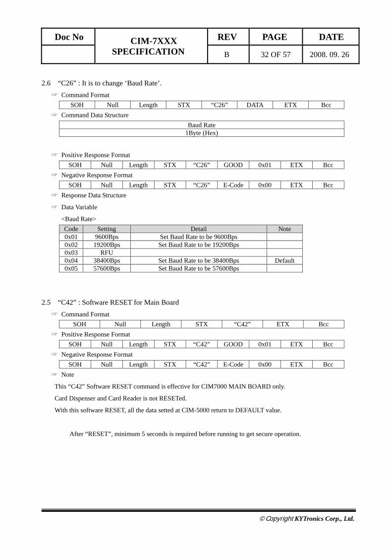
2.6 “C26” : It is to change ‘Baud Rate’. ☞ Command Format
SOH Null Length STX “C26” DATA ETX Bcc ☞ Command Data Structure
Baud Rate 1Byte (Hex)
☞ Positive Response Format SOH Null Length STX “C26” GOOD 0x01 ETX Bcc
☞ Negative Response Format SOH Null Length STX “C26” E-Code 0x00 ETX Bcc
☞ Response Data Structure
☞ Data Variable
<Baud Rate> Code Setting Detail Note 0x01 9600Bps Set Baud Rate to be 9600Bps 0x02 19200Bps Set Baud Rate to be 19200Bps 0x03 RFU 0x04 38400Bps Set Baud Rate to be 38400Bps Default 0x05 57600Bps Set Baud Rate to be 57600Bps
2.5 “C42” : Software RESET for Main Board ☞ Command Format
SOH Null Length STX “C42” ETX Bcc ☞ Positive Response Format
SOH Null Length STX “C42” GOOD 0x01 ETX Bcc ☞ Negative Response Format
SOH Null Length STX “C42” E-Code 0x00 ETX Bcc ☞ Note
This “C42” Software RESET command is effective for CIM7000 MAIN BOARD only.
Card Dispenser and Card Reader is not RESETed.
With this software RESET, all the data setted at CIM-5000 return to DEFAULT value.
After “RESET”, minimum 5 seconds is required before running to get secure operation.

Doc No CIM-7XXX SPECIFICATION
REV PAGE DATE
B 33 OF 57 2008. 09. 26
©Copyright KYTronics Corp., Ltd.
3 MOVE
3.1 “C31” : It is to take a card from Stacker and to move it to Card Reader / Writer Module. ☞ Command Format
SOH Null Length STX “C31” DATA ETX Bcc ☞ Command Data Structure
Stacker Module 1Byte (Hex) 1Byte (Hex)
☞ Positive Response Format SOH Null Length STX “C31” GOOD 0x01 ETX Bcc
☞ Negative Response Format SOH Null Length STX “C31” E-Code 0x00 ETX Bcc
☞ Data Variable
<Stacker> Code Setting Detail 0x01 Stacker 1 Select Stacker 1 0x02 Stacker 2 Select Stacker 2 0x03 RFU 0x04 Stacker 3 Select Stacker 3 0x05 Stacker 4 Select Stacker 4
<Module> Code Setting Detail 0x01 MSRW Card transport to MSRW Module 0x02 IC Card transport to IC Module 0x03 RF Card transport to RF Module
3.2 “C32” : It is take card to Card Reader / Writer Module ☞ Command Format
SOH Null Length STX “C32” DATA ETX Bcc ☞ Command Data Structure
Module 1Byte (Hex)
☞ Positive Response Format SOH Null Length STX “C32” GOOD 0x01 DATA ETX Bcc
☞ Negative Response Format SOH Null Length STX “C32” E-Code 0x00 ETX Bcc
☞ Data Variable
<Module> Code Setting Detail 0x01 MSRW Card transport to MSRW Module 0x02 IC Card transport to IC Module 0x03 RF Card transport to RF Module

Doc No CIM-7XXX SPECIFICATION
REV PAGE DATE
B 34 OF 57 2008. 09. 26
©Copyright KYTronics Corp., Ltd.
3.3 “C34” : It takes card to Bin Box (Capture) ☞ Command Format
SOH Null Length STX “C34” ETX Bcc ☞ Positive Response Format
SOH Null Length STX “C34” GOOD 0x01 ETX Bcc ☞ Negative Response Format
SOH Null Length STX “C34” E-Code 0x00 ETX Bcc ☞ Details
Capture card is stored in Bin Box in the back of CIM-6X0. If the Box is full, it causes an error.
3.4 “C36” : Dispense the card to front and Drop it out of the unit. ☞ Command Format
SOH Null Length STX “C36” ETX Bcc ☞ Positive Response Format
SOH Null Length STX “C36” GOOD 0x01 ETX Bcc ☞ Negative Response Format
SOH Null Length STX “C36” E-Code 0x00 ETX Bcc ☞ Note
The CIM-7xxx model with bezel or shutter can not use “C36” command.
3.5 “C37” : Dispense the card to front and hold it at the exit roller of the unit. ☞ Command Format
SOH Null Length STX “C37” ETX Bcc ☞ Positive Response Format
SOH Null Length STX “C37” GOOD 0x01 ETX Bcc ☞ Negative Response Format
SOH Null Length STX “C37” E-Code 0x00 ETX Bcc
Doc No CIM-7XXX SPECIFICATION
REV PAGE DATE
B 35 OF 57 2008. 09. 26
©Copyright KYTronics Corp., Ltd.
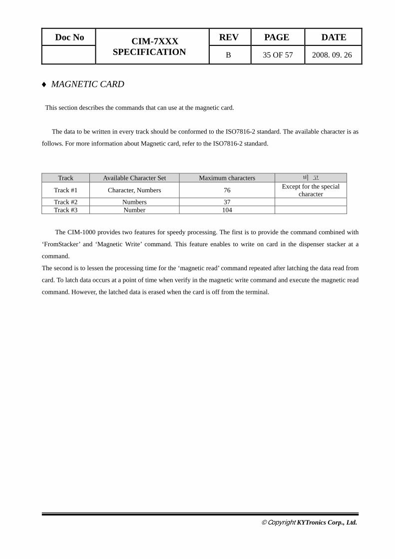
♦ MAGNETIC CARD
This section describes the commands that can use at the magnetic card.
The data to be written in every track should be conformed to the ISO7816-2 standard. The available character is as
follows. For more information about Magnetic card, refer to the ISO7816-2 standard.
Track Available Character Set Maximum characters 비 고
Track #1 Character, Numbers 76 Except for the special character
Track #2 Numbers 37 Track #3 Number 104
The CIM-1000 provides two features for speedy processing. The first is to provide the command combined with
‘FromStacker’ and ‘Magnetic Write’ command. This feature enables to write on card in the dispenser stacker at a
command.
The second is to lessen the processing time for the ‘magnetic read’ command repeated after latching the data read from
card. To latch data occurs at a point of time when verify in the magnetic write command and execute the magnetic read
command. However, the latched data is erased when the card is off from the terminal.
Doc No CIM-7XXX SPECIFICATION
REV PAGE DATE
B 36 OF 57 2008. 09. 26
©Copyright KYTronics Corp., Ltd.
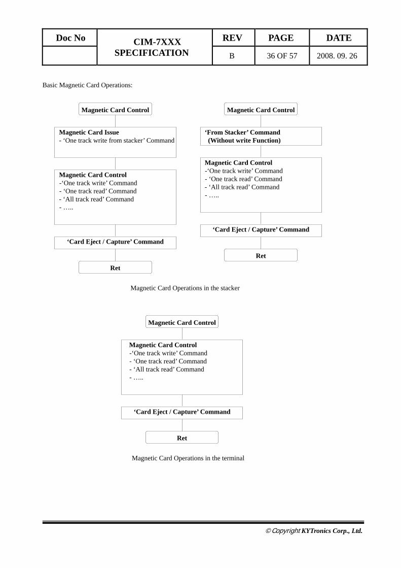
Basic Magnetic Card Operations:
Magnetic Card Issue - ‘One track write from stacker’ Command
Magnetic Card Control
Magnetic Card Control -‘One track write’ Command - ‘One track read’ Command
- ‘All track read’ Command - …..
‘Card Eject / Capture’ Command
Ret
‘From Stacker’ Command (Without write Function)
Magnetic Card Control
Magnetic Card Control -‘One track write’ Command - ‘One track read’ Command
- ‘All track read’ Command - …..
‘Card Eject / Capture’ Command
Ret
Magnetic Card Operations in the stacker
Magnetic Card Control
Magnetic Card Control -‘One track write’ Command - ‘One track read’ Command - ‘All track read’ Command - …..
‘Card Eject / Capture’ Command
Ret
Magnetic Card Operations in the terminal
Doc No CIM-7XXX SPECIFICATION
REV PAGE DATE
B 37 OF 57 2008. 09. 26
©Copyright KYTronics Corp., Ltd.
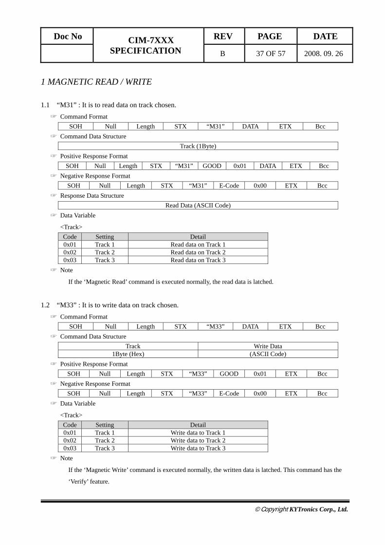
1 MAGNETIC READ / WRITE
1.1 “M31” : It is to read data on track chosen. ☞ Command Format
SOH Null Length STX “M31” DATA ETX Bcc ☞ Command Data Structure
Track (1Byte) ☞ Positive Response Format
SOH Null Length STX “M31” GOOD 0x01 DATA ETX Bcc ☞ Negative Response Format
SOH Null Length STX “M31” E-Code 0x00 ETX Bcc ☞ Response Data Structure
Read Data (ASCII Code) ☞ Data Variable
<Track> Code Setting Detail 0x01 Track 1 Read data on Track 1 0x02 Track 2 Read data on Track 2 0x03 Track 3 Read data on Track 3
☞ Note
If the ‘Magnetic Read’ command is executed normally, the read data is latched.
1.2 “M33” : It is to write data on track chosen. ☞ Command Format
SOH Null Length STX “M33” DATA ETX Bcc ☞ Command Data Structure
Track Write Data 1Byte (Hex) (ASCII Code)
☞ Positive Response Format SOH Null Length STX “M33” GOOD 0x01 ETX Bcc
☞ Negative Response Format SOH Null Length STX “M33” E-Code 0x00 ETX Bcc
☞ Data Variable
<Track> Code Setting Detail 0x01 Track 1 Write data to Track 1 0x02 Track 2 Write data to Track 2 0x03 Track 3 Write data to Track 3
☞ Note
If the ‘Magnetic Write’ command is executed normally, the written data is latched. This command has the
‘Verify’ feature.
Doc No CIM-7XXX SPECIFICATION
REV PAGE DATE
B 38 OF 57 2008. 09. 26
©Copyright KYTronics Corp., Ltd.
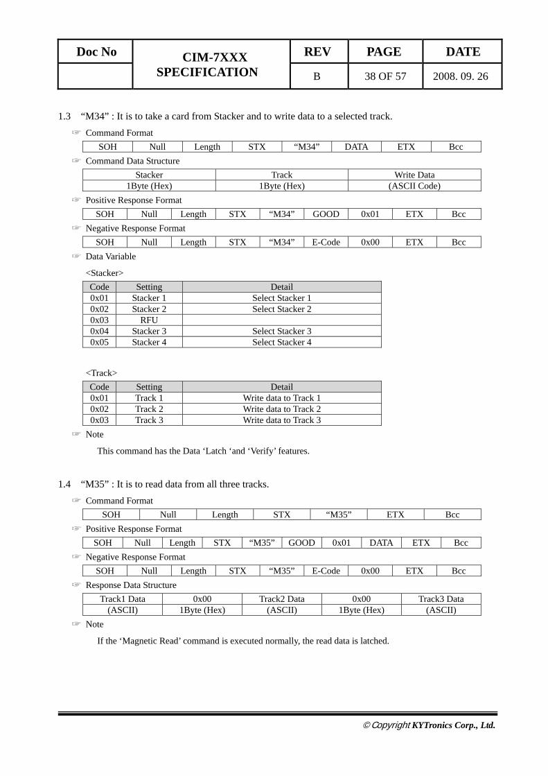
1.3 “M34” : It is to take a card from Stacker and to write data to a selected track. ☞ Command Format
SOH Null Length STX “M34” DATA ETX Bcc ☞ Command Data Structure
Stacker Track Write Data 1Byte (Hex) 1Byte (Hex) (ASCII Code)
☞ Positive Response Format SOH Null Length STX “M34” GOOD 0x01 ETX Bcc
☞ Negative Response Format SOH Null Length STX “M34” E-Code 0x00 ETX Bcc
☞ Data Variable
<Stacker> Code Setting Detail 0x01 Stacker 1 Select Stacker 1 0x02 Stacker 2 Select Stacker 2 0x03 RFU 0x04 Stacker 3 Select Stacker 3 0x05 Stacker 4 Select Stacker 4
<Track> Code Setting Detail 0x01 Track 1 Write data to Track 1 0x02 Track 2 Write data to Track 2 0x03 Track 3 Write data to Track 3
☞ Note
This command has the Data ‘Latch ‘and ‘Verify’ features.
1.4 “M35” : It is to read data from all three tracks. ☞ Command Format
SOH Null Length STX “M35” ETX Bcc ☞ Positive Response Format
SOH Null Length STX “M35” GOOD 0x01 DATA ETX Bcc ☞ Negative Response Format
SOH Null Length STX “M35” E-Code 0x00 ETX Bcc ☞ Response Data Structure
Track1 Data 0x00 Track2 Data 0x00 Track3 Data (ASCII) 1Byte (Hex) (ASCII) 1Byte (Hex) (ASCII)
☞ Note
If the ‘Magnetic Read’ command is executed normally, the read data is latched.

Doc No CIM-7XXX SPECIFICATION
REV PAGE DATE
B 39 OF 57 2008. 09. 26
©Copyright KYTronics Corp., Ltd.
2 CLEANING
2.1 “M51” : It is to clean Magnetic Head mounted inside MSRW. ☞ Command Format
SOH Null Length STX “M51” ETX Bcc ☞ Positive Response Format
SOH Null Length STX “M51” GOOD 0x01 ETX Bcc ☞ Negative Response Format
SOH Null Length STX “M51” E-Code 0x00 ETX Bcc
♦ IC CARD
This section describes the commands that can use at the IC card and Memory card.
The IC card should conform to the ISO7816-4 T=0 and T=1 , these cards is available
The applicable models in the CIM7000 Series are the CIM720, CIM740, CIM750, CIM770, and the available
commands are as follows.
Item Cm0 Cm1 Cm2 Detail Note
IC CONTROL ‘I’ ‘2’ ‘1’ IC Card Reset ‘I’ ‘2’ ‘2’ IC Card Direct Control

Doc No CIM-7XXX SPECIFICATION
REV PAGE DATE
B 40 OF 57 2008. 09. 26
©Copyright KYTronics Corp., Ltd.
1 IC CONTROL
1.1 “I21” : Reset the IC card and receive the ATR from card. ☞ Command Format
SOH Null Length STX “I21” ETX Bcc ☞ Positive Response Format
SOH Null Length STX “I21” GOOD 0x01 DATA ETX Bcc ☞ Negative Response Format
SOH Null Length STX “I21” E-Code 0x00 ETX Bcc ☞ Response Data Structure
Length _ High Length _ Low ATR (Answer To Request) 2Byte N Byte
☞ Example
SAMSUNG SCOS ATR High 8Byte 0x3B 0x6B 0x00 0x00 0x80 0x31 0x80 0x63 Low 7Byte 0x53 0x46 0x01 0x83 0x03 0x90 0x00
Length

Doc No CIM-7XXX SPECIFICATION
REV PAGE DATE
B 41 OF 57 2008. 09. 26
©Copyright KYTronics Corp., Ltd.
1.2 “I22” : Control the card conforming to the ISO 7816 T = 0 and T =1 , ISO 7816 – 4 standard directly. ☞ Command Format
SOH Null Length STX “I22” DATA ETX Bcc ☞ Command Data Structure
Length _ High Length _ Low IC Command & IC Data 2Byte N Byte
☞ Positive Response Format SOH Null Length STX “I22” GOOD 0x01 DATA ETX Bcc
☞ Negative Response Format SOH Null Length STX “I22” E-Code 0x00 ETX Bcc
☞ Response Data Structure Length _ High Length _ Low IC Data (or Result)
2Byte N Byte
☞ IC Command & IC Data Structure
Length CLA INS P1 P2 Lc Data Le 2Byte 1Byte 1Byte 1Byte 1Byte 1Byte Lc Byte 1Byte
Length _ High Length _ Low
1Byte 1Byte
CLA Class Note INS Instruction P1 Offset(High Value) P2 Offset(Low Value) Lc A number of data to transfer Max Value : 255 Data Data to Transfer Le A number of data to receive
Length
Length
Basic format of Packet of T = 0 command
Fixed Variable
Length

Doc No CIM-7XXX SPECIFICATION
REV PAGE DATE
B 42 OF 57 2008. 09. 26
©Copyright KYTronics Corp., Ltd.
☞ Format of T = 0 Command
Command INS Code (Hex Value)
Read Binary Command B0 Write Binary Command D0 Update Binary Command D6 Erase Binary Command 0E Read Record(s) Command B2 Write Record Command D2 Append Record Command E2 Update Record Command DC Get Data Command CA Put Data Command DA Select File Command A4 Verify Command 20 Internal Authenticate Command 88 External Authenticate Command 82 Get Challenge Command 84 Manage Channel Command 70
For more information, refer to the ISO 7816 – 4 standard.

Doc No CIM-7XXX SPECIFICATION
REV PAGE DATE
B 43 OF 57 2008. 09. 26
©Copyright KYTronics Corp., Ltd.
♦ RF CARD
This section describes the commands that can use at the ‘RF CARD’.
The RF Module of his model supports only the MIFARE card.
To use the RF card, you need to initialize at first.
Setting and updating of the secret key and secret key index.
Item Cm0 Cm1 Cm2 Detail Note
RF READ / WRITE
‘R’ ‘3’ ‘1’ RF Card Read in Block Range ‘R’ ‘3’ ‘2’ RF Card Write in Block Range ‘R’ ‘3’ ‘6’ Read RF card data in sector range ‘R’ ‘3’ ‘7’ Write RF card data in sector range
BALANCE ‘R’ ‘4’ ‘1’ Increases balance in RF card ‘R’ ‘4’ ‘2’ Decreases balance in RF card
SECRET KEY
CHANGE
‘R’ ‘5’ ‘1’ Change ‘Secret Key’ to other Key ‘R’ ‘5’ ‘2’ Change ‘Secret Key’ to all the same Key value ‘R’ ‘5’ ‘3’ Select ‘Secret Key Index’ ‘R’ ‘5’ ‘4’ Change RF Card ‘Secret Key’ to other key
RF DETECT ‘R’ ‘6’ ‘1’ Check RF card in antenna area
RF Initialization
Return
‘R51’ Command
‘R53’ Command
Change ‘Secret Key’ to other key
Select ‘Secret Key Index’
RF Module Initialization
Doc No CIM-7XXX SPECIFICATION
REV PAGE DATE
B 44 OF 57 2008. 09. 26
©Copyright KYTronics Corp., Ltd.
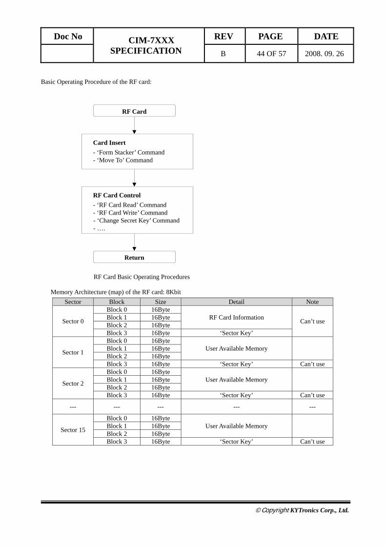
Basic Operating Procedure of the RF card:
Memory Architecture (map) of the RF card: 8Kbit Sector Block Size Detail Note
Sector 0
Block 0 16Byte RF Card Information Can’t use Block 1 16Byte
Block 2 16Byte Block 3 16Byte ‘Sector Key’
Sector 1
Block 0 16Byte User Available Memory Block 1 16Byte
Block 2 16Byte Block 3 16Byte ‘Sector Key’ Can’t use
Sector 2
Block 0 16Byte User Available Memory Block 1 16Byte
Block 2 16Byte Block 3 16Byte ‘Sector Key’ Can’t use
--- --- --- --- ---
Sector 15
Block 0 16Byte User Available Memory Block 1 16Byte
Block 2 16Byte Block 3 16Byte ‘Sector Key’ Can’t use
Card Insert - ‘Form Stacker’ Command - ‘Move To’ Command
RF Card
Return
RF Card Control - ‘RF Card Read’ Command - ‘RF Card Write’ Command
- ‘Change Secret Key’ Command - ….
RF Card Basic Operating Procedures
Doc No CIM-7XXX SPECIFICATION
REV PAGE DATE
B 45 OF 57 2008. 09. 26
©Copyright KYTronics Corp., Ltd.
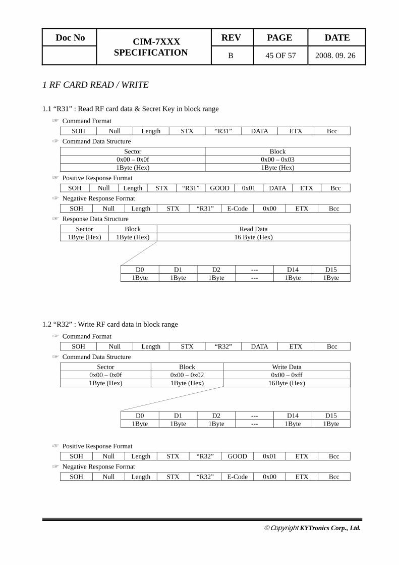
1 RF CARD READ / WRITE
1.1 “R31” : Read RF card data & Secret Key in block range ☞ Command Format
SOH Null Length STX “R31” DATA ETX Bcc ☞ Command Data Structure
Sector Block 0x00 – 0x0f 0x00 – 0x03 1Byte (Hex) 1Byte (Hex)
☞ Positive Response Format SOH Null Length STX “R31” GOOD 0x01 DATA ETX Bcc
☞ Negative Response Format SOH Null Length STX “R31” E-Code 0x00 ETX Bcc
☞ Response Data Structure Sector Block Read Data
1Byte (Hex) 1Byte (Hex) 16 Byte (Hex)
D0 D1 D2 --- D14 D15
1Byte 1Byte 1Byte --- 1Byte 1Byte
1.2 “R32” : Write RF card data in block range ☞ Command Format
SOH Null Length STX “R32” DATA ETX Bcc ☞ Command Data Structure
Sector Block Write Data 0x00 – 0x0f 0x00 – 0x02 0x00 – 0xff 1Byte (Hex) 1Byte (Hex) 16Byte (Hex)
D0 D1 D2 --- D14 D15
1Byte 1Byte 1Byte --- 1Byte 1Byte
☞ Positive Response Format SOH Null Length STX “R32” GOOD 0x01 ETX Bcc
☞ Negative Response Format SOH Null Length STX “R32” E-Code 0x00 ETX Bcc
Doc No CIM-7XXX SPECIFICATION
REV PAGE DATE
B 46 OF 57 2008. 09. 26
©Copyright KYTronics Corp., Ltd.
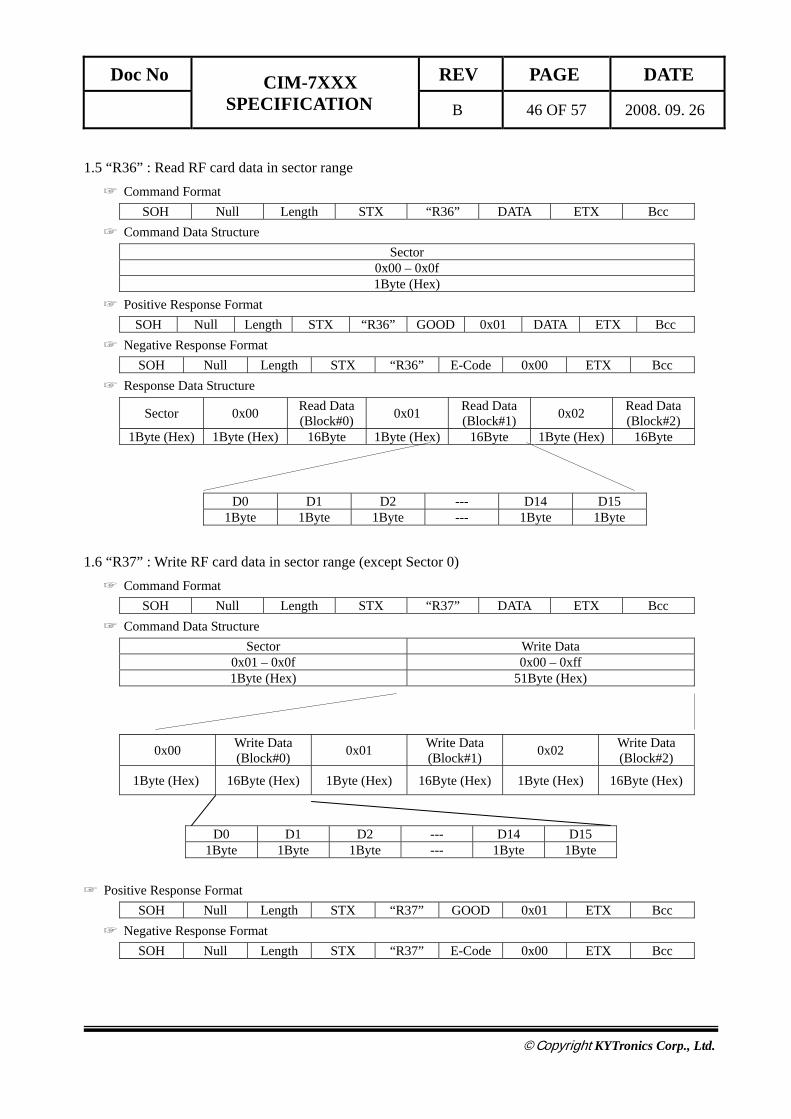
1.5 “R36” : Read RF card data in sector range ☞ Command Format
SOH Null Length STX “R36” DATA ETX Bcc ☞ Command Data Structure
Sector 0x00 – 0x0f 1Byte (Hex)
☞ Positive Response Format SOH Null Length STX “R36” GOOD 0x01 DATA ETX Bcc
☞ Negative Response Format SOH Null Length STX “R36” E-Code 0x00 ETX Bcc
☞ Response Data Structure
Sector 0x00 Read Data (Block#0) 0x01 Read Data
(Block#1) 0x02 Read Data (Block#2)
1Byte (Hex) 1Byte (Hex) 16Byte 1Byte (Hex) 16Byte 1Byte (Hex) 16Byte
D0 D1 D2 --- D14 D15
1Byte 1Byte 1Byte --- 1Byte 1Byte
1.6 “R37” : Write RF card data in sector range (except Sector 0) ☞ Command Format
SOH Null Length STX “R37” DATA ETX Bcc ☞ Command Data Structure
Sector Write Data 0x01 – 0x0f 0x00 – 0xff 1Byte (Hex) 51Byte (Hex)
☞ Positive Response Format SOH Null Length STX “R37” GOOD 0x01 ETX Bcc
☞ Negative Response Format SOH Null Length STX “R37” E-Code 0x00 ETX Bcc
0x00 Write Data (Block#0) 0x01 Write Data
(Block#1) 0x02 Write Data (Block#2)
1Byte (Hex) 16Byte (Hex) 1Byte (Hex) 16Byte (Hex) 1Byte (Hex) 16Byte (Hex)
D0 D1 D2 --- D14 D15 1Byte 1Byte 1Byte --- 1Byte 1Byte

Doc No CIM-7XXX SPECIFICATION
REV PAGE DATE
B 47 OF 57 2008. 09. 26
©Copyright KYTronics Corp., Ltd.
2 BALANCE 2.1 “R41” : Increment the balance of card to the specified amount. ☞ Command Format
SOH Null Length STX “R41” DATA ETX Bcc ☞ Command Data Structure
Sector Block Index Value 0x00 – 0x0f 0x00 – 0x02 0x00000000 – 0xffffffff 1Byte (Hex) 1Byte (Hex) 4Byte (Hex)
V0 V1 V2 V3
0x00-0xff 0x00-0xff 0x00-0xff 0x00-0xff 1Byte(Hex, LSB) 1Byte(Hex) 1Byte(Hex) 1Byte(Hex, MSB)
☞ Positive Response Format SOH Null Length STX “R41” GOOD 0x01 ETX Bcc
☞ Negative Response Format SOH Null Length STX “R41” E-Code 0x00 ETX Bcc
☞ Note
The balance should be written in the Electronic Purse format in the card.
2.1 “R42” : Decrement the balance of card to the specified amount.. ☞ Command Format
SOH Null Length STX “R42” DATA ETX Bcc ☞ Command Data Structure
Sector Block Index Value 0x00 – 0x0f 0x00 – 0x02 0x00000000 – 0xffffffff 1Byte (Hex) 1Byte (Hex) 4Byte (Hex)
V0 V1 V2 V3
0x00-0xff 0x00-0xff 0x00-0xff 0x00-0xff 1Byte(Hex, LSB) 1Byte(Hex) 1Byte(Hex) 1Byte(Hex, MSB)
☞ Positive Response Format SOH Null Length STX “R42” GOOD 0x01 ETX Bcc
☞ Negative Response Format SOH Null Length STX “R42” E-Code 0x00 ETX Bcc
☞ Note
The balance should be written in the Electronic Purse format in the card.

Doc No CIM-7XXX SPECIFICATION
REV PAGE DATE
B 48 OF 57 2008. 09. 26
©Copyright KYTronics Corp., Ltd.
3 SECRET KEY 3.1 “R51” : Change ‘Secret Key’ to a new key ☞ Command Format
SOH Null Length STX “R51” DATA ETX Bcc ☞ Command Data Structure
Sector KEY A KEY B 0x00 – 0x0f 0x00 – 0xff 0x00 – 0xff 1Byte (Hex) 6Byte (Hex) 6Byte (Hex)
☞ Positive Response Format SOH Null Length STX “R51” GOOD 0x01 ETX Bcc
☞ Negative Response Format SOH Null Length STX “R51” E-Code 0x00 ETX Bcc
☞ Note
KEY A : FFFFFFFFFFFF
KEY B : FFFFFFFFFFFF
3.2 “R52” : Change ‘Secret Key’ to all the same key value ☞ Command Format
SOH Null Length STX “R52” DATA ETX Bcc ☞ Command Data Structure
KEY A KEY B 0x00 – 0xff 0x00 – 0xff 6Byte (Hex) 6Byte (Hex)
☞ Positive Response Format SOH Null Length STX “R52” GOOD 0x01 ETX Bcc
☞ Negative Response Format SOH Null Length STX “R52” E-Code 0x00 ETX Bcc
☞ Note
KEY A : FFFFFFFFFFFF
KEY B : FFFFFFFFFFFF
Doc No CIM-7XXX SPECIFICATION
REV PAGE DATE
B 49 OF 57 2008. 09. 26
©Copyright KYTronics Corp., Ltd.
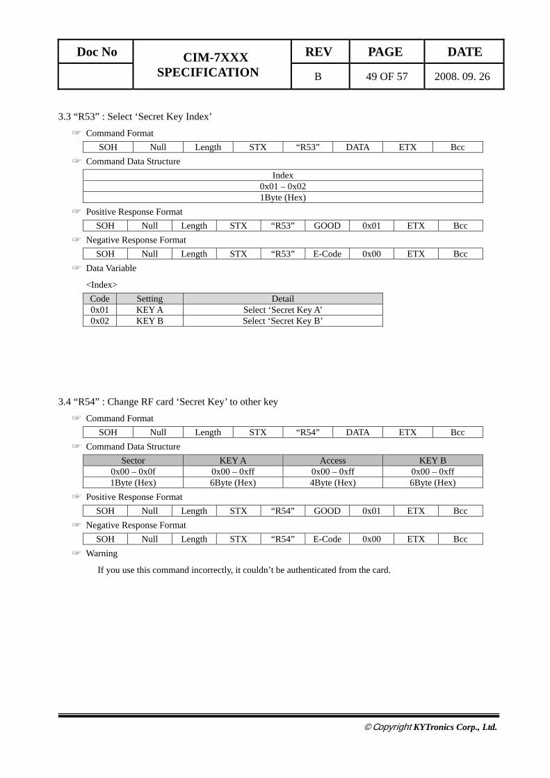
3.3 “R53” : Select ‘Secret Key Index’ ☞ Command Format
SOH Null Length STX “R53” DATA ETX Bcc ☞ Command Data Structure
Index 0x01 – 0x02 1Byte (Hex)
☞ Positive Response Format SOH Null Length STX “R53” GOOD 0x01 ETX Bcc
☞ Negative Response Format SOH Null Length STX “R53” E-Code 0x00 ETX Bcc
☞ Data Variable
<Index> Code Setting Detail 0x01 KEY A Select ‘Secret Key A’ 0x02 KEY B Select ‘Secret Key B’
3.4 “R54” : Change RF card ‘Secret Key’ to other key ☞ Command Format
SOH Null Length STX “R54” DATA ETX Bcc ☞ Command Data Structure
Sector KEY A Access KEY B 0x00 – 0x0f 0x00 – 0xff 0x00 – 0xff 0x00 – 0xff 1Byte (Hex) 6Byte (Hex) 4Byte (Hex) 6Byte (Hex)
☞ Positive Response Format SOH Null Length STX “R54” GOOD 0x01 ETX Bcc
☞ Negative Response Format SOH Null Length STX “R54” E-Code 0x00 ETX Bcc
☞ Warning
If you use this command incorrectly, it couldn’t be authenticated from the card.
Doc No CIM-7XXX SPECIFICATION
REV PAGE DATE
B 50 OF 57 2008. 09. 26
©Copyright KYTronics Corp., Ltd.
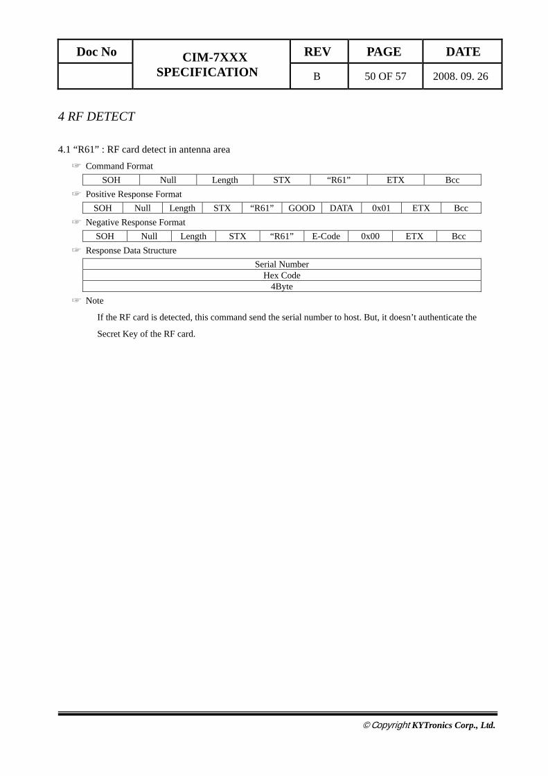
4 RF DETECT 4.1 “R61” : RF card detect in antenna area ☞ Command Format
SOH Null Length STX “R61” ETX Bcc ☞ Positive Response Format
SOH Null Length STX “R61” GOOD DATA 0x01 ETX Bcc ☞ Negative Response Format
SOH Null Length STX “R61” E-Code 0x00 ETX Bcc ☞ Response Data Structure
Serial Number Hex Code
4Byte ☞ Note
If the RF card is detected, this command send the serial number to host. But, it doesn’t authenticate the
Secret Key of the RF card.

Doc No CIM-7XXX SPECIFICATION
REV PAGE DATE
B 51 OF 57 2008. 09. 26
©Copyright KYTronics Corp., Ltd.
ERROR DETAIL
<GOOD> Code : 0x0000
Description: Normal Execution
Procedures: None
<NOT_DEFINE_COMMAND> Code : 0x2001
Description : Using the command that does not defined in this model.
Action : Use the valid command in this model.
<NOT_USE_COMMAND> Code : 0x2002
Description : Not available command in this model.
Action : Use the valid command in this model.
<COMM_FRAME_ERROR> Code : 0x2003
Description : Sending the command that has the invalid communication frame.
Action : Check the data format and the corresponding module specification.
<CARD_JAM> Code : 0x2004
Description : When the card is jammed.
Action : Remove the jammed card.
<NO_CARD> Code : 0x2005
Description : No cards.
Action : Insert the card.
Doc No CIM-7XXX SPECIFICATION
REV PAGE DATE
B 52 OF 57 2008. 09. 26
©Copyright KYTronics Corp., Ltd.
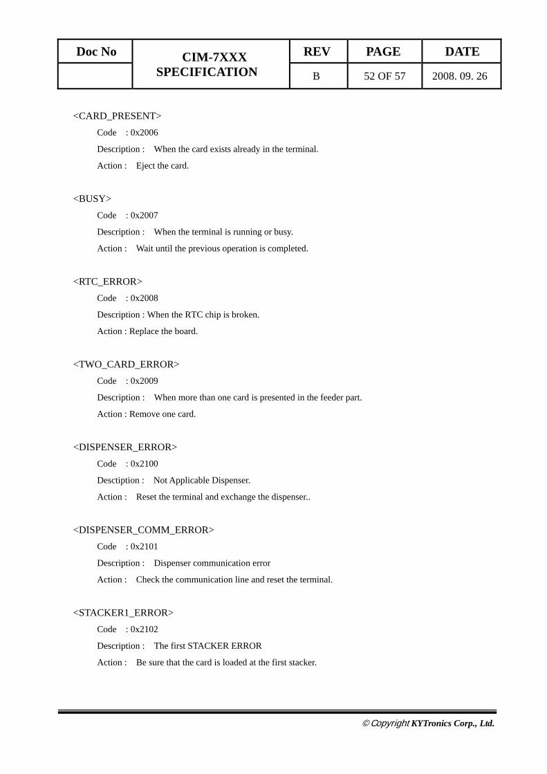
<CARD_PRESENT> Code : 0x2006
Description : When the card exists already in the terminal.
Action : Eject the card.
<BUSY> Code : 0x2007
Description : When the terminal is running or busy.
Action : Wait until the previous operation is completed.
<RTC_ERROR> Code : 0x2008
Description : When the RTC chip is broken.
Action : Replace the board.
<TWO_CARD_ERROR> Code : 0x2009
Description : When more than one card is presented in the feeder part.
Action : Remove one card.
<DISPENSER_ERROR> Code : 0x2100
Desctiption : Not Applicable Dispenser.
Action : Reset the terminal and exchange the dispenser..
<DISPENSER_COMM_ERROR> Code : 0x2101
Description : Dispenser communication error
Action : Check the communication line and reset the terminal.
<STACKER1_ERROR> Code : 0x2102
Description : The first STACKER ERROR
Action : Be sure that the card is loaded at the first stacker.
Doc No CIM-7XXX SPECIFICATION
REV PAGE DATE
B 53 OF 57 2008. 09. 26
©Copyright KYTronics Corp., Ltd.
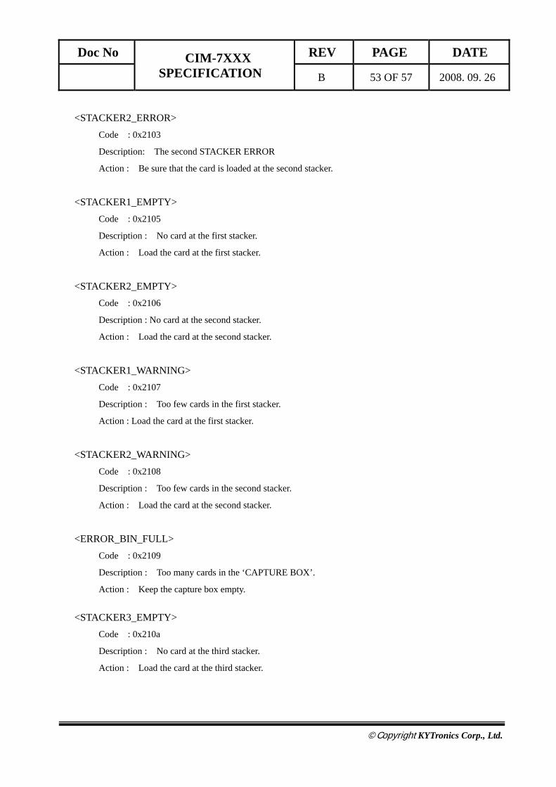
<STACKER2_ERROR> Code : 0x2103
Description: The second STACKER ERROR
Action : Be sure that the card is loaded at the second stacker.
<STACKER1_EMPTY>
Code : 0x2105
Description : No card at the first stacker.
Action : Load the card at the first stacker.
<STACKER2_EMPTY> Code : 0x2106
Description : No card at the second stacker.
Action : Load the card at the second stacker.
<STACKER1_WARNING> Code : 0x2107
Description : Too few cards in the first stacker.
Action : Load the card at the first stacker.
<STACKER2_WARNING> Code : 0x2108
Description : Too few cards in the second stacker.
Action : Load the card at the second stacker.
<ERROR_BIN_FULL> Code : 0x2109
Description : Too many cards in the ‘CAPTURE BOX’.
Action : Keep the capture box empty. <STACKER3_EMPTY>
Code : 0x210a
Description : No card at the third stacker.
Action : Load the card at the third stacker.
Doc No CIM-7XXX SPECIFICATION
REV PAGE DATE
B 54 OF 57 2008. 09. 26
©Copyright KYTronics Corp., Ltd.
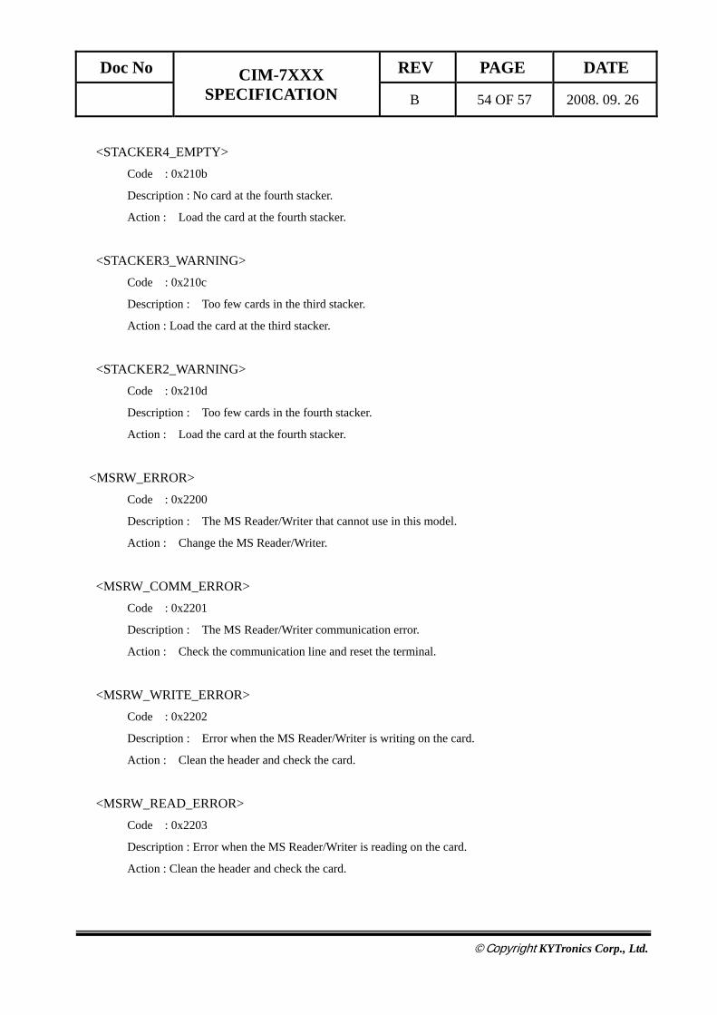
<STACKER4_EMPTY> Code : 0x210b
Description : No card at the fourth stacker.
Action : Load the card at the fourth stacker.
<STACKER3_WARNING> Code : 0x210c
Description : Too few cards in the third stacker.
Action : Load the card at the third stacker.
<STACKER2_WARNING> Code : 0x210d
Description : Too few cards in the fourth stacker.
Action : Load the card at the fourth stacker.
<MSRW_ERROR>
Code : 0x2200
Description : The MS Reader/Writer that cannot use in this model.
Action : Change the MS Reader/Writer.
<MSRW_COMM_ERROR> Code : 0x2201
Description : The MS Reader/Writer communication error.
Action : Check the communication line and reset the terminal.
<MSRW_WRITE_ERROR> Code : 0x2202
Description : Error when the MS Reader/Writer is writing on the card.
Action : Clean the header and check the card.
<MSRW_READ_ERROR> Code : 0x2203
Description : Error when the MS Reader/Writer is reading on the card.
Action : Clean the header and check the card.
Doc No CIM-7XXX SPECIFICATION
REV PAGE DATE
B 55 OF 57 2008. 09. 26
©Copyright KYTronics Corp., Ltd.
<IC_CONTACT_ERROR> Code : 0x2204
Description : Error while the terminal contacts the IC card.
Action : Be sure that the current card is an IC card.
<IC_CONTROL_ERROR> Code : 0x2205
Description : Error while the terminal executes the IC card command.
Action : Check if the command is able to use in the contacted card.
<MSRW_BLANK_ERROR> Code : 0x2205
Description : Error while the terminal executes the IC card command.
Action : Check if the command is able to use in the contacted card.
<RF_ERROR> Code : 0x2300
Description : Unavailable RF module.
Action : Change the RF MODULE
<RF_COMM_ERROR> Code : 0x2301
Description : Communication error at the RF Module.
Action : Check the connection socket
<RF_AUTHEN_ERROR> Code : 0x2302
Description : Authentication Error at the RF Module.
Action : Change the ‘SECRET KEY’
<RF_WRITE_ERROR> Code : 0x2303
Description : Error while the terminal writes at the RF Card.
Action : Be sure that the card exists in the detection range.
Doc No CIM-7XXX SPECIFICATION
REV PAGE DATE
B 56 OF 57 2008. 09. 26
©Copyright KYTronics Corp., Ltd.
<RF_READ_ERROR> Code : 0x2304
Description : Error while the terminal reads at the RF Card.
Action: Be sure that the card exists in the detection range.
<RF_DETECT_ERROR> Error Code : 0x2305
Description : No RF Card.
Action : Insert the RF Card into the terminal.
<RF_AMOUNT_ERROR>
Error Code : 0x2306
Description : Error while the terminal increases(or decreases) the balance at the RF card.
Action : Tune the RF module.
Doc No CIM-7XXX SPECIFICATION
REV PAGE DATE
B 57 OF 57 2008. 09. 26
©Copyright KYTronics Corp., Ltd.
PRECAUTIONS
1. Check if the card exists in stacker. Otherwise, it may not issue the card.
2. Check the communication line
1) Communication Port, Baud, Parity, and Data Bit, etc.
3. Check the ‘CAPTURE BOX’.
The ‘BIN FULL’ error might be caused, if you turn on the power in condition that the card exists in the ‘
CAPTURE BOX’ behind the terminal.