ciemat: sl 53-2 & 53-4atasks organisation and qa task sl53.2: safety important components (sic)
DESCRIPTION
CIEMAT: SL 53-2 & 53-4aTasks Organisation and QA Task SL53.2: Safety Important Components (SIC) Task SL53.2: Safety operational limits Task SL53.4a: Outline of the description of the maintenance programme. CIEMAT: SL 53-2 & 53-4aTasks Organisation and QA - PowerPoint PPT PresentationTRANSCRIPT

Progress meeting EISS5
CIEMAT: SL 53-2 & 53-4aTasks
•Organisation and QA•Task SL53.2: Safety Important Components (SIC)•Task SL53.2: Safety operational limits•Task SL53.4a: Outline of the description of the maintenance programme

Progress meeting EISS5
CIEMAT: SL 53-2 & 53-4aTasksOrganisation and QA
•CIEMAT CO-ORDINATES, REVIEW DRAFTS, AND ACCEPTS REPORTS PRIOR TO SUBMITTAL
–Project co-ordinator: Beatriz Brañas, assisted by Pablo Zuloaga–Support by Safety Department: Caridad Roldán, Paloma Díaz-Arocas
•PUBLIC CALL FOR BIDS: –Spec with all Project and QA requirements–Commented by EFDA, ITER-France before consultation–Public consultation published in Official Journal (BOE)–Assigned to IBERTEF
•Task 53.8 (Hot cell functions during decommissioning) not yet launched, pending on design approval).
Progress meeting EISS5
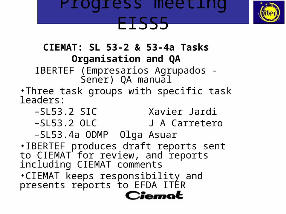
CIEMAT: SL 53-2 & 53-4a TasksOrganisation and QA
IBERTEF (Empresarios Agrupados - Sener) QA manual
•Three task groups with specific task leaders: –SL53.2 SIC Xavier Jardi–SL53.2 OLC J A Carretero–SL53.4a ODMP Olga Asuar
•IBERTEF produces draft reports sent to CIEMAT for review, and reports including CIEMAT comments•CIEMAT keeps responsibility and presents reports to EFDA ITER

Task SL53.2:Safety Important Components (SIC)

5
Task Objectives: For RPrS
Definition of criteria for the safety classification of ITER systems and components
As a function of the above criteria, preparation of a list of safety-important systems and components (SIC), including:
– Type of component (isolation valve, cryopump, etc)
– Safety function of the component
– How the component performs its safety function
– Seismic classification

6
Task Objectives: For support document
Identification of applicable codes and standards
Demonstration that the list of systems and components classified as SIC is complete by cross-checking it with the normal, incidental and accidental situations

7
Level of Completion
Objetive %
Definition of criteria for the safety classification of ITER systems and components
100%
List of systems and components with SIC classification 80%
Codes and standards 70%
Cross-checking of the list 10%

8
SIC Classification Criteria
SIC structures, systems and components are those relied upon to remain functional during and following the reference events to ensure:
• Confinement safety function, including the ancillary safety functions protecting it, and
• Personnel protection by limitation of exposure to radiation of workers and environment
9
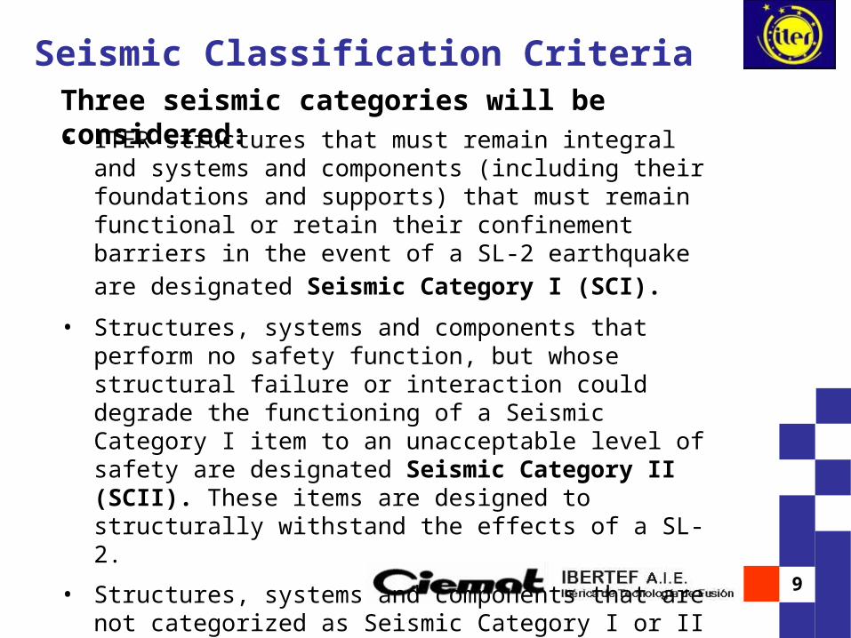
Seismic Classification CriteriaThree seismic categories will be considered:• ITER structures that must remain integral and systems and
components (including their foundations and supports) that must remain functional or retain their confinement barriers in the event of a SL-2 earthquake are designated Seismic
Category I (SCI).
• Structures, systems and components that perform no safety function, but whose structural failure or interaction could degrade the functioning of a Seismic Category I item to an unacceptable level of safety are designated Seismic Category II (SCII). These items are designed to structurally withstand the effects of a SL-2.
• Structures, systems and components that are not categorized as Seismic Category I or II are designated no Seismic Category (NSC).
10
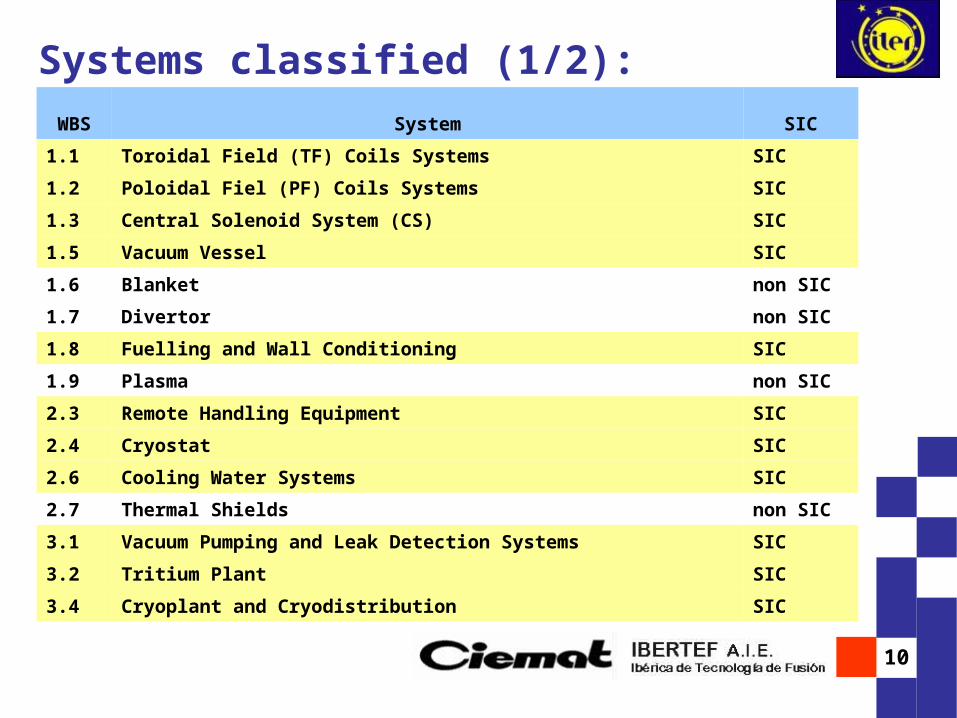
Systems classified (1/2):WBS System SIC
1.1 Toroidal Field (TF) Coils Systems SIC
1.2 Poloidal Fiel (PF) Coils Systems SIC
1.3 Central Solenoid System (CS) SIC
1.5 Vacuum Vessel SIC
1.6 Blanket non SIC
1.7 Divertor non SIC
1.8 Fuelling and Wall Conditioning SIC
1.9 Plasma non SIC
2.3 Remote Handling Equipment SIC
2.4 Cryostat SIC
2.6 Cooling Water Systems SIC
2.7 Thermal Shields non SIC
3.1 Vacuum Pumping and Leak Detection Systems SIC
3.2 Tritium Plant SIC
3.4 Cryoplant and Cryodistribution SIC

11
Systems classified (2/2):
WBS System SIC
4.1 Coil Power Supplies SIC
4.2 Heating and Current Drive Power Supplies non SIC
4.3 Steady State Electrical Power Network SIC
4.5 Supervisory Control System non SIC
4.6 Interlock System SIC
4.7 Poloidal Field Control non SIC
5.1 Ion Cyclotron H&CD SIC
5.2 Electron Cyclotron H&CD SIC
5.3 Neutral Beam H&CD SIC
5.4 Lower Hybrid H&CD SIC
5.5 Diagnostics SIC
5.6 Test Blankets SIC
12
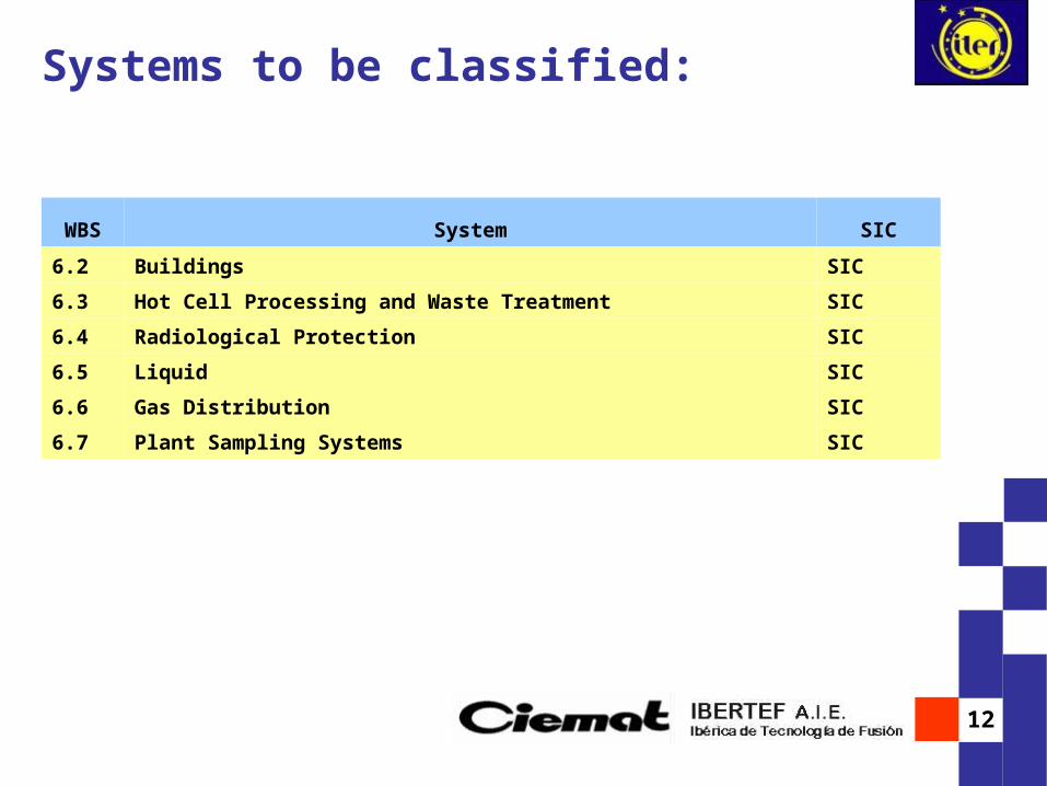
Systems to be classified:
WBS System SIC
6.2 Buildings SIC
6.3 Hot Cell Processing and Waste Treatment SIC
6.4 Radiological Protection SIC
6.5 Liquid SIC
6.6 Gas Distribution SIC
6.7 Plant Sampling Systems SIC

13
Task sample for RPrS : WBS 1.1, 1.2 and 1.3
SIC CLASSIFICATION SUMMARY
Main ComponentsSIC
Classification
Safety Function Safety RequirementsSeismic
Classification
WBS 1.1: TOROIDAL FIELD (TF) COILS SYSTEM
1. TF coils non SIC - - NSC
2. Feeders through the cryostat SIC Confinement Confinement function with cryostat SCI (S)
3. Other auxiliary systems non SIC - - NSC
4. Magnet gravity supports SIC - - SCI (S)
5. Other mechanical structures non SIC - - NSC
WBS 1.2: POLOIDAL FIELD (PF) COILS SYSTEM
1. PF Coils non SIC - - NSC
2. Feeders through the cryostat SIC Confinement Confinement function with cryostat SCI (S)
3. Other auxiliary systems non SIC - - NSC
4. Correction coils non SIC - - NSC
WBS 1.3: CENTRAL SOLENOID SYSTEM (CS)
1. Central solenoid non SIC - - NSC
2. Feeders through the cryostat SIC Confinement Confinement function with cryostat SCI (S)
3. Other auxiliary systems non SIC - - NSC

14
Task sample for RPrS : WBS 2.6 (1/2)
SIC CLASSIFICATION SUMMARY
Main ComponentsSIC
Classification
Safety Function
Safety RequirementsSeismic
Classification
WBS 2.6: COOLING WATER SYSTEMS
4. Vacuum vessel primary heat transfer system (PHTS)
4.1Circulating pump SIC Confinement
Confinement of HTS source terms. Provide heat removal by natural circulation under accident
SCI (S)
4.2Water-Air Heat Exchangers (3 per loop) SIC Confinement
Confinement of HTS source terms. Provide heat removal by natural circulation under accident
SCI (S)
4.3 Electtrical Heater SIC Confinement Confinement of HTS source terms. SCI (S)
4.4Pneumatic Pressurizer SIC Confinement
Confinement of HTS source terms. Provide heat removal by natural circulation under accident
SCI (S)
4.5Isolation Valves SIC Confinement
Confinement of HTS source terms. Provide heat removal by natural circulation under accident
SCI (SF)
4.6Control valves SIC Confinement
Confinement of HTS source terms. Provide heat removal by natural circulation under accident
SCI (SF)
4.7Piping and associated valves SIC Confinement
Confinement of HTS source terms. Provide heat removal by natural circulation under accident
SCI (S)
4.8 Filter SIC Confinement Confinement of HTS source terms SCI (S)
4.9Relief valves SIC Confinement
Confinement of HTS source terms. Provide heat removal by natural circulation under accident
SCI (S)
4.10 Pressure relief tank SIC Confinement Confinement of HTS source terms SCI (S)
4.11 Drainage tank SIC Confinement Confinement of in-vessel source terms and hydrogen SCI (S)
4.12 Drain sump tank SIC Confinement Confinement of HTS source terms SCI (S)

15
Task sample for RPrS : WBS 2.6 (2/2)
SIC CLASSIFICATION SUMMARY
Main ComponentsSIC
Classification
Safety Function
Safety RequirementsSeismic
Classification
WBS 2.6: COOLING WATER SYSTEMS
4.13 Sump pump SIC Confinement Confinement of HTS source terms SCI (S)
4.14 Drain cooler SIC Confinement Prevent coolant loss SCI (S)
4.15 Isolation valves from/to HXs SIC Confinement Prevent coolant loss SCI (SF)
4.16Isolation valves to N-VDS SIC Confinement
Confinement of HTS source terms. Provide heat removal by natural circulation under accident
SCI (SF)
4.17Isolation valves to associated CCWS SIC Confinement
Confinement of HTS source terms. Provide heat removal by natural circulation under accident
SCI (SF)
4.18 Associated loops of Draining & Refilling System
SIC Confinement Confinement of HTS source terms SCI (S)
4.19
Helium Supply System non SIC
4.20 Isolation valves to Helium Suply System SIC Confinement Confinement of HTS source terms SCI (SF)
4.21 Associated loops of Drying System SIC Confinement Confinement of HTS source terms SCI (S)
4.22Isolation valves (Evacuation Unit) SIC Confinement
Confinement of HTS source terms. Provide heat removal by natural circulation under accident
SCI (SF)

16
SIC Classification Summary (sample)Main Components
SIC Classification
Safety Function Safety RequirementsSeismic
ClassificationCodes and Standars
1. Cryostat1.1 Cryostat vessel SIC Confinement Confinement barrier for in-vessel source term and
hydrogen including some maintenance activitiesSCI (S) ASME VIII Div 2 for
vessels
1.2 Penetrations SIC Confinement Confinement barrier for in-vessel source term and hydrogen including some maintenance activities
SCI (S)
1.3 Support structure ASME Section III-NF for support
1.4 Excryostat guard pipes SIC Confinement Forms part of the confinement barrier for HTS source terms; blow down path into TCWS vaults
SCI (S) ANSI/ASME B31.3 for piping (Category M)
1.5 In-Cryostat Ice Detection System SIC Confinement Prevention of ozone formation from ice condensing in high radiation fields; for protection of confinement barriers; redundant
SCI (S)
1.6 Other components not having safety function non SIC - - NCS
2. Venting and overpressure protection system2.1 UHV Angle valve SIC Confinement For protection of cryostat and surrounding structures SCI (SF) ASME B 16.34 for valves
2.2 Back-up valve SIC Confinement For protection of cryostat and surrounding structures SCI (SF) ASME B 16.34 for valves
2.3 Pump For protection of cryostat and surrounding structures SCI (S) ASME B73.1M/73.2M for pumps
2.4 Piping SIC Confinement For protection of cryostat and surrounding structures SCI (S) ANSI/ASME B31.3 for piping (Category M)
2.5 Other components not having safety function non SIC - - NCS
3. Vacuum vessel pressure supression system3.1 Pressure supression tank SIC Confinement Limit pressure in VV under accident conditions;
Confinement of in-vessel source terms and hydrogen during accident conditions
SCI (S) ASME VIII Div 2
3.2 Relief pipes SIC Confinement Limit pressure in VV under accident conditions; Confinement of in-vessel source terms and hydrogen during accident conditions
SCI (S) ASME VIII Div 2
3.3 Rupture disks SIC Confinement Limit pressure in VV under accident conditions; Confinement of in-vessel source terms and hydrogen during accident conditions
SCI (S) ASME VIII Div 2
3.4 Bleed line non SIC -3.5 UHV angle valves SIC Confinement Limit pressure in VV under accident conditions;
Confinement of in-vessel source terms and hydrogen during accident conditions
SCI (S) ASME VIII Div 2
3.6 Other components not having safety function non SIC - - NCS
4. Thermal shield non SIC - - NSC
SIC CLASSIFICATION SUMMARY
WBS 2.4: CRYOSTAT
17
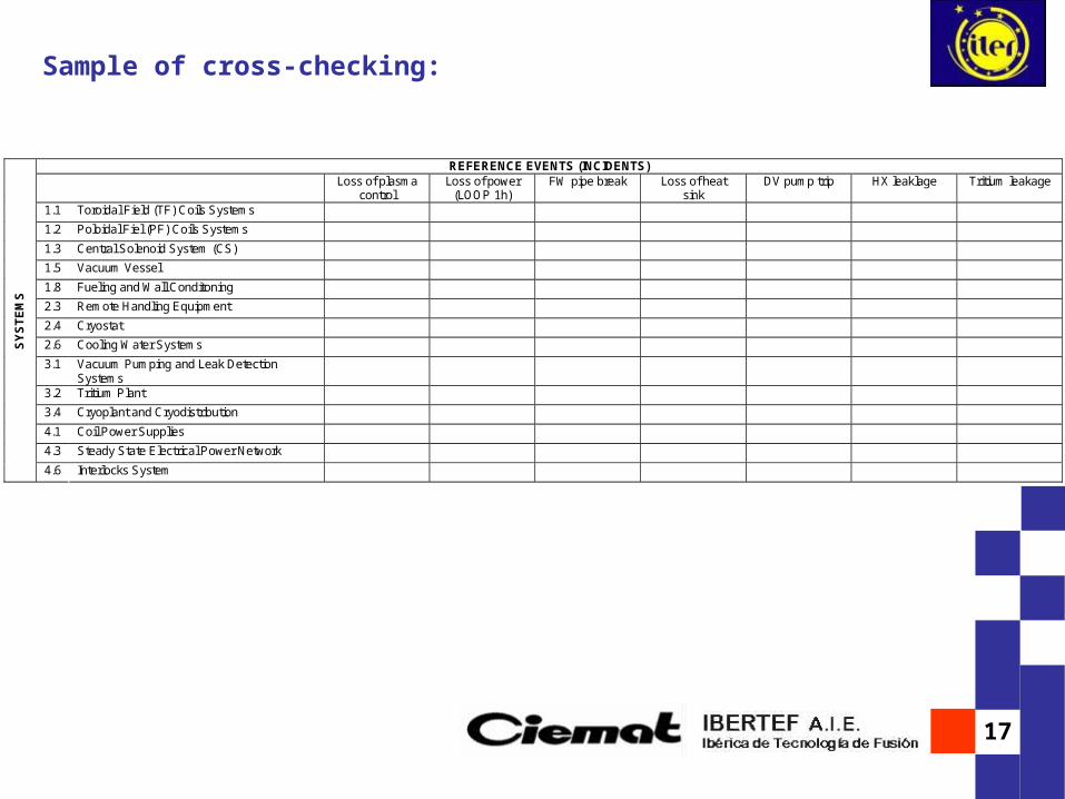
Sample of cross-checking:
REFERENCE EVENTS (INCIDENTS)
Loss of plasma control
Loss of power (LOOP 1h)
FW pipe break Loss of heat sink
DV pump trip HX leaklage Tritium leakage
1.1 Toroidal Field (TF) Coils Systems 1.2 Poloidal Fiel (PF) Coils Systems 1.3 Central Solenoid System (CS) 1.5 Vacuum Vessel 1.8 Fueling and Wall Conditoning 2.3 Remote Handling Equipment 2.4 Cryostat 2.6 Cooling Water Systems 3.1 Vacuum Pumping and Leak Detection
Systems
3.2 Tritium Plant 3.4 Cryoplant and Cryodistribution 4.1 Coil Power Supplies 4.3 Steady State Electrical Power Network
SY
ST
EM
S
4.6 Interlocks System

18
Task SL53.2: Safety operational limits

19
OLCs are a set of operating rules that include safety limits, safety system settings and operational limits on equipment and conditions on inventories, surveillance and administrative requirements.
Introduction (1/2)
Objectives:
• To ensure safe operation and protection of site personnel, the public and the environment from radiological hazards• To guarantee the required operation flexibility
Most of the limits are controlled automatically, such as for pressure or concentration. Others (such as inventories) are controlled through administrative procedures.

20
Introduction (2/2)
LC
LF
LF
LS
LS
LD
LC: limites de conduite
LF: limites de fonctionnement
LS: limites de sûreté
LD: limites de dimensionnement
OLC classification in France:
OLC interrelationship
21
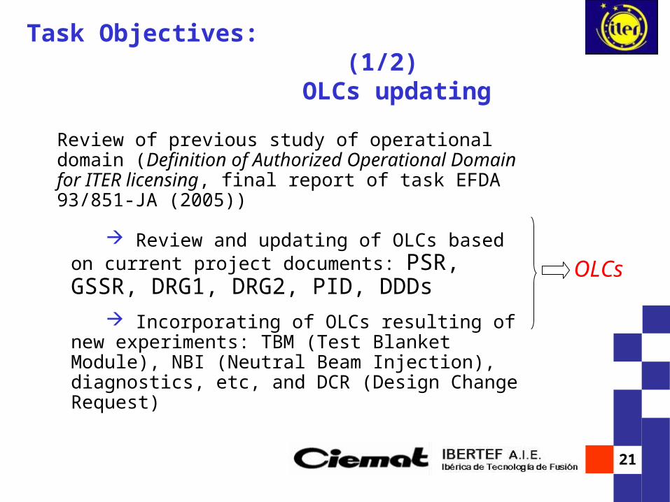
Task Objectives: (1/2) OLCs updating
Review of previous study of operational domain (Definition of Authorized Operational Domain for ITER licensing, final report of task EFDA 93/851-JA (2005))
Review and updating of OLCs based on current project documents: PSR, GSSR, DRG1, DRG2, PID, DDDs
Incorporating of OLCs resulting of new experiments: TBM (Test Blanket Module), NBI (Neutral Beam Injection), diagnostics, etc, and DCR (Design Change Request)
OLCs
22
Selection of a series of limits more representative for safety (Top Level Safety OLCs), combining them in a reduced group of parameters
Task Objectives: (2/2) Top Safety OLCs
With a view to their inclusion in the DAC (Décret d´Autorisation de Création)
The result has been embodied in a report
(Top Level Safety OLCs)
23
Review of Input Documents
Input data: ITER Technical Web (Baseline Documentation)
New versions:
PID: Project integration document, Release 2.0
September 2005
No OLC changes
Other/New Inputs ?
New experiments, Test Blanket Module, Neutral Beam
Injection, diagnostics, DCR… Open issue

24
Safety Top OLCs: Methodology
1. OLCs of the various systems were grouped per parameter (for example: tritium inventory and content, dust amount, dose, pressure, loads, temperature, leaktightness, etc).
2. The most significant parameters for safety (confinement, limitation of external exposure, residual power evacuation) were selected.

25
Safety Top OLCs: List (1)
Tritium inventory in vacuum vessel, tritium plant and hot cell
Tritium concentration in water systems
Tritium concentration to isolate and initiate ADS
Efficiency of Detritiation System
Dust and activated products in vacuum vessel and water
systems

26
Safety Top OLCs: List (2)
Radiation and dose levels for personnel evacuation
Leak tightness in system components forming part of
primary or secondary confinement barriers, in tritium plant,
ventilation and detritiation, in cooling water and heat rejection
system and in buildings
Pressure of primary and secondary confinement barriers
VVPSS bleed and drain line actuation pressure, and
opening pressure of VVPSS rupture disks
Level of water in VVPSS tank
27
Activities in course
Documentation of the cross-checking performed between Top OLCs and the Reference Events.
Table of the surveillance method / instrumentation foreseen in the project for Top OLC.

28
Safety Top OLCs: List (3)
VV temperature in Baking
Degraded levels of Voltage/Time delays for initiating full
transfer/start of Class III loads (switch DG)
Time intervention of Fusion Power Shutdown System
Top OLCs to be discussed
Maximum fusion power
TF magnetic energy dumping
VV heat transfer system

29
Top Level OLCs EX Table SampleTop Level OLC Limit Possible instrument or
procedure to measure the limit
Rationale for choice of the limit ITER safety analysis Documentation reference
Tritium inventory in the vacuum vessel
< 450 g The amount of tritium is assessed monitoring inventories and flows
Radiological consequence assessments remain valid provided that these inventories remain lower than the specified limits (maximum inventory project guidelines). For the safety assessment in GSSR, as noted in Volume III, assessment inventory values are used to provide margins for uncertainty
PSR, GSSR I.5.2.1, PID
3.1.1.2
Tritium content in Cooling water VVPHTS (Vacuum vessel cooling system).
<0.0001 g/m3 (~37 MBq/kg)
Monitoring concentrations To reduce as a mminimum if a leak in the water-to-air heat exchanger happens
PSR, GSSR I.5.2.1, PID
3.1.1.2
Tritium (radioactivity) leak rate for automatic or manual isolation of Heat Rejection System (HRS)
automatic <600 MBq/s; manual after sampling TBD
Monitoring systems to detect large leak. Detection is based on on-line measurement of tritium
Safety analysis assumes automatic isolation of HRS (two minutes’ delay in the signal and three minutes in valve actuation are assumed) in case of a higher HTO leak rate (Heat exchanger tube rupture)
GSSR VII 1.2.4, 3.4.2
Leak rate of system components confining in-vessel source terms, forming part of primary or secondary barrier
<1 volume %/day at 0.2 Mpa
Monitoring systems to detect leak
This leak rate limit is required to prevent air ingress that could result in hazardous air/H2 mixtures and protect against the spread of radioactive materials.
PID 3.1.2.1
30
Conclusions and Comments (1/2)
• OLCs are based on the safety analysis taking into account the provisions made in the design. Therefore, OLCs and their correlated procedures will be updated throughout the various ITER phases, like detailed design, commissioning test and results of specific R&D like those on tritium and dust measurement and control.
• The surveillance programme relevant to all OLCs -including the frequency, the detailed procedures to carry out, the evaluation of the results and the corrective actions, when necessary- will be defined at a later stage of the ITER project.
•In certain cases (like tritium inventory in vacuum vessel) the OLC is a more restrictive value than the assessment used in the GSSR safety analysis. Lower project guidelines are set to account for uncertainties and these values are pending confirmation of feasibility.

31
Conclusions and Comments (2/2)
TOP Safety OLC document derives a minimum set of conditions which define the top main safety parameters that should be retained with regard to the DAC (Décret d´Autorisation de Création), grouping various constraints as much as practical and reducing the total list.
Therefore, this document intends to show a group of the most representative parameters analyzed in previous study and these top level safety OLCs can be completed or modified in accordance with different criteria, changes or design upgrades.
“Definition of Authorized Operational Domain for ITER Licensing”, Issue Rev 0, March 2005 (Task order EFDA 93/851-JA)”
Task SL53.4a: Outline of the description of the maintenance programme
O. AsuarM. Vázquez
33
Task Objectives
Identification of SIC systems and components
– Description of the systems above,
– Find their flow diagrams,
– Identification of their main components, location and amount.
Identify hands-on schedule maintenance requirements for the SIC systems/components identified above
Breakdown of the maintenance operations including:
– Objective,
– Operation sequence,
– Initial conditions of the components,
– Tools,
– Waste estimation,
– Reference documents.
Non-active support systems (e.g., electrical systems) are excluded from this report as they do not have any impact on worker dosis.
34
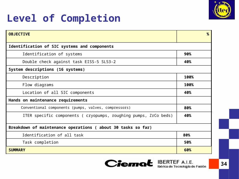
Level of Completion
100%Flow diagrams
100%Description
System descriptions (16 systems)
40%Double check against task EISS-5 SL53-2
90%Identification of systems
Identification of SIC systems and components
%OBJECTIVE
60%SUMMARY
50%Task completion
80%Identification of all task
Breakdown of maintenance operations ( about 30 tasks so far)
40%ITER specific components ( cryopumps, roughing pumps, ZrCo beds)
80%Conventional components (pumps, valves, compressors)
Hands on maintenance requirements
40%Location of all SIC components
35
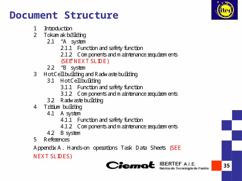
Document Structure1 Introduction 2 Tokamak building
2.1 “A” system 2.1.1 Function and safety function 2.1.2 Components and maintenance requirements (SEE NEXT SLIDE)
2.2 “B” system 3 Hot Cell building and Radwaste building
3.1 Hot Cell building 3.1.1 Function and safety function 3.1.2 Components and maintenance requirements
3.2 Radwaste building 4 Tritium building
4.1 A system 4.1.1 Function and safety function 4.1.2 Components and maintenance requirements
4.2 B system 5 References
Appendix A. Hands-on operations Task Data Sheets (SEE
NEXT SLIDES)

36
Components and maintenance requirementsExample:
Component Safety Function
Quantity / location
Frequency Maintenance requirements
Pressure Suppression tank
Y 1 (Crane Hall, Green, access zone B, Ref 6)
Plant outages
During outages, visual inspection of the surfaces (Ref 2)
Leak rate test
For maintenance operations see task 3 of Appendix A
Seals and Gaskets
N - Plant outages
When opened, visual inspection of the surfaces (Ref 2)
Bolted Connections
N - Plant outages
Visual inspection and bolted torque or tension test (Ref 2)
Relief Pipes Y 3 Plant outages
Visual inspection
Rupture discs in the relief valves
Y 3 Plant outages
To be replaced in accordance with the rules specified in ASME section XI, division 1.(From Ref 2)
From ref 4 rupture disc are relocated inside the NB cell for confinement purposes. For maintenance operations of rupture disc see section 2.14 of this document.

37
Appendix A: Breakdown of maintenance operationsTask sample : motor driven valve maintenance operations (1/3)
Task Objective:
Disassemble the motor driven valve, inspect the plant item visually in order to detect possible problem areas.
Lube all screws and nuts Target plant:
Generic- All plant motor driven plants
Frequency:
5 years
Start Point:
The plant in shut down operation mode The valve is isolate, drained and without any pressure Electrical connexions of the valves are disconnected from the grid
Assumptions:
Time consumed in each operation has been estimated Main Issues:
There are many types of valves, operations shown in this task are based on the preventive maintenance of valves in Nuclear Power Plants, model UN-122

38
Task sample : motor driven valve maintenance operations (2/3)
24.2 Lube all screws and nuts
4.1 Repeat operations done in the disassembly but in reverse order
4 Assembly
53.2 Inspect valve seat.
203.1 Inspect valve body and look for any cracks using dye penetrating, if necessary.
3 Clean all valve components
22 Inspection
201.3 Remove valve stem and valve disc
101.2 Remove valve cover
101.1 Remove actuator
1. Disassembly
CommentsEstimated
Time man-hr/task
WorkerPosition
Operation
Handling Sequence:
Next to the component
Next to the component
Next to the component
Next to the component
30

39
Task aample : motor driven valve maintenance operations (3/3)
1. CE-T-MM-0271 Revisión general válvula motorizada de globo, tipo UN-122, CN Almaraz-Trillo
References
ResolutionIssue of concern
Outstanding Issues
Manipulator (for handling and cleaning)
CharacteristicsTooling Function:
HANDLING TOOL
Screw driver
Manufacturer requirements
40
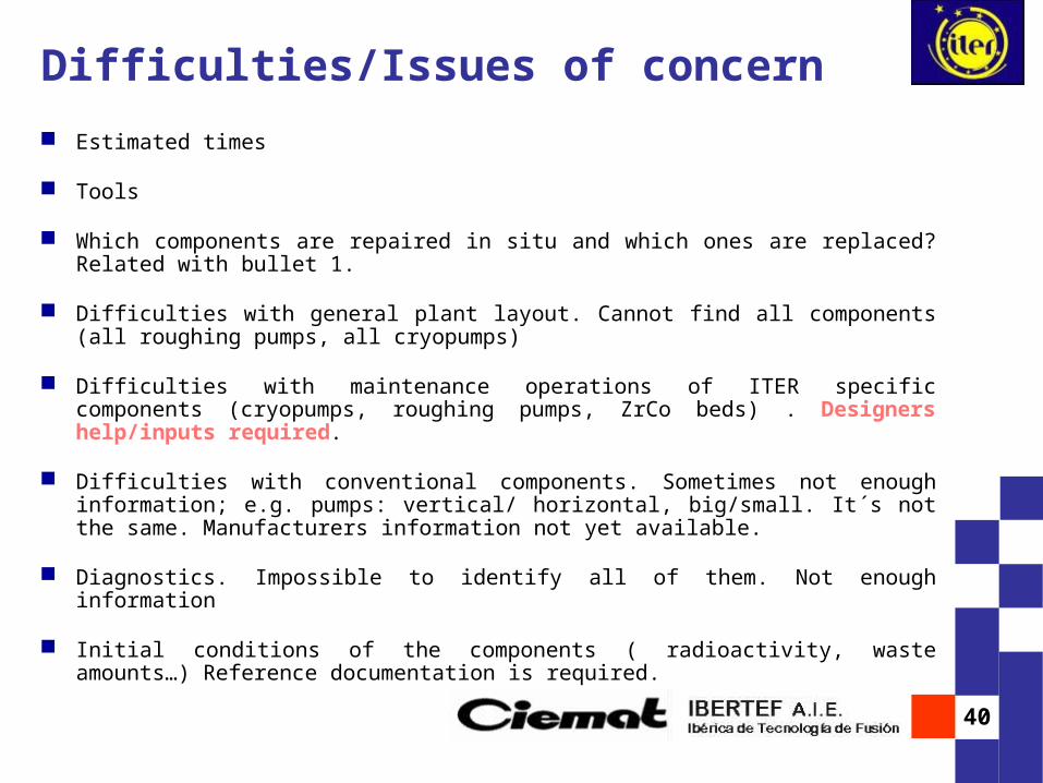
Estimated times
Tools
Which components are repaired in situ and which ones are replaced? Related with bullet 1.
Difficulties with general plant layout. Cannot find all components (all roughing pumps, all cryopumps)
Difficulties with maintenance operations of ITER specific components (cryopumps, roughing pumps, ZrCo beds) . Designers help/inputs required.
Difficulties with conventional components. Sometimes not enough information; e.g. pumps: vertical/ horizontal, big/small. It´s not the same. Manufacturers information not yet available.
Diagnostics. Impossible to identify all of them. Not enough information
Initial conditions of the components ( radioactivity, waste amounts…) Reference documentation is required.
Difficulties/Issues of concern