cics - nxp semiconductors · important notice to users while every effort has been made to ensure...
TRANSCRIPT
M68ICS05COM/D
April 1998
M68ICS05CHC705C IN-CIRCUIT SIMULATOR
OPERATOR’S MANUAL
© MOTOROLA Inc., 1998; All Rights Reserved
Fre
esc
ale
Se
mic
on
du
cto
r, I
Freescale Semiconductor, Inc.
For More Information On This Product, Go to: www.freescale.com
nc
...
Important Notice to Users
While every effort has been made to ensure the accuracy of all information in this document,Motorola assumes no liability to any party for any loss or damage caused by errors or omissionsor by statements of any kind in this document, its updates, supplements, or special editions,whether such errors are omissions or statements resulting from negligence, accident, or any othercause. Motorola further assumes no liability arising out of the application or use of anyinformation, product, or system described herein; nor any liability for incidental or consequentialdamages arising from the use of this document. Motorola disclaims all warranties regarding theinformation contained herein, whether expressed, implied, or statutory, including impliedwarranties of merchantability or fitness for a particular purpose . Motorola makes norepresentation that the interconnection of products in the manner described herein will notinfringe on existing or future patent rights, nor do the descriptions contained herein imply thegranting or license to make, use or sell equipment constructed in accordance with thisdescription.
Trademarks
This document includes these trademarks:
Motorola and the Motorola logo are registered trademarks of Motorola Inc.
IBM is a registered trademark of IBM Corporation.
Windows is a registered trademark of Microsoft Corporation.
CASM05W, ICS05CW, and WinIDE software are P & E Microcomputer Systems, Inc, 1996;all rights reserved.
Motorola Inc. is an Equal Opportunity /Affirmative Action Employer.
Fre
esc
ale
Se
mic
on
du
cto
r, I
Freescale Semiconductor, Inc.
For More Information On This Product, Go to: www.freescale.com
nc
...
CONTENTS
M68ICS05COM/D iii
TABLE OF CONTENTS
CHAPTER 1 INTRODUCTION
1.1 OVERVIEW...........................................................................................................................1-11.2 TOOLKIT COMPONENTS...................................................................................................1-11.3 HARDWARE AND SOFTWARE REQUIREMENTS.........................................................1-21.4 TOOLKIT FEATURES..........................................................................................................1-21.5 SPECIFICATIONS ................................................................................................................1-31.6 ABOUT THIS USER’S MANUAL.......................................................................................1-31.7 QUICK START INSTRUCTIONS........................................................................................1-4
CHAPTER 2 POD INSTALLATION
2.1 OVERVIEW...........................................................................................................................2-12.2 INSTALLING THE M68ICS05C POD.................................................................................2-1
CHAPTER 3 SOFTWARE INSTALLATION AND INITIALIZATION
3.1 OVERVIEW...........................................................................................................................3-13.2 THE ICS05CW SOFTWARE COMPONENTS....................................................................3-1
3.2.1 The WinIDE Editor .......................................................................................................3-13.2.2 CASM05W....................................................................................................................3-13.2.3 ICS05CW ......................................................................................................................3-2
3.3 INSTALLING THE ICS05CW SOFTWARE........................................................................3-23.3.1 Installation Steps ...........................................................................................................3-23.3.2 Starting the ICS05CW Software ...................................................................................3-33.3.3 ICS Communication......................................................................................................3-3
CHAPTER 4 THE WinIDE USER INTERFACE
4.1 OVERVIEW...........................................................................................................................4-14.2 THE WINDOWS INTEGRATED DEVELOPMENT ENVIRONMENT.............................4-14.3 WinIDE MAIN WINDOW ....................................................................................................4-2
4.3.1 Main Window Functions...............................................................................................4-24.3.2 Main Window Components ..........................................................................................4-2
Fre
esc
ale
Se
mic
on
du
cto
r, I
Freescale Semiconductor, Inc.
For More Information On This Product, Go to: www.freescale.com
nc
...
CONTENTS
M68ICS05COM/Div
CHAPTER 4 THE WinIDE USER INTERFACE (continued)
4.4 GETTING STARTED............................................................................................................4-34.4.1 Prerequisites for Starting the WinIDE Editor................................................................4-34.4.2 Starting the WinIDE Editor...........................................................................................4-44.4.3 Opening Source Files ....................................................................................................4-44.4.4 Navigating in the WinIDE Editor..................................................................................4-44.4.5 Using Markers ...............................................................................................................4-5
4.5 COMMAND-LINE PARAMETERS.....................................................................................4-64.6 WinIDE TOOLBAR...............................................................................................................4-74.7 WinIDE MENUS ...................................................................................................................4-94.8 WinIDE FILE OPTIONS.....................................................................................................4-11
4.8.1 New File ......................................................................................................................4-114.8.2 Open File .....................................................................................................................4-124.8.3 Save File ......................................................................................................................4-124.8.4 Save File As.................................................................................................................4-124.8.5 Close File.....................................................................................................................4-134.8.6 Print File ......................................................................................................................4-134.8.7 Print Setup ...................................................................................................................4-144.8.8 Exit ..............................................................................................................................4-14
4.9 WinIDE EDIT OPTIONS.....................................................................................................4-144.9.1 Undo ............................................................................................................................4-144.9.2 Redo ............................................................................................................................4-154.9.3 Cut ...............................................................................................................................4-154.9.4 Copy ............................................................................................................................4-154.9.5 Paste ............................................................................................................................4-164.9.6 Delete...........................................................................................................................4-164.9.7 Select All .....................................................................................................................4-16
4.10 WinIDE ENVIRONMENT OPTIONS ..............................................................................4-164.10.1 Open Project ..............................................................................................................4-174.10.2 Save Project...............................................................................................................4-184.10.3 Save Project As .........................................................................................................4-184.10.4 Close/New Project.....................................................................................................4-184.10.5 Setup Environment ....................................................................................................4-18
4.10.5.1 The General Environment Tab.........................................................................4-194.10.5.2 General Editor Tab ...........................................................................................4-204.10.5.3 Assembler/Compiler Tab .................................................................................4-224.10.5.4 Executable 1 (Debugger) and Executable 2 (Programmer) Tab.......................4-26
Fre
esc
ale
Se
mic
on
du
cto
r, I
Freescale Semiconductor, Inc.
For More Information On This Product, Go to: www.freescale.com
nc
...
CONTENTS
M68ICS05COM/D v
CHAPTER 4 THE WinIDE USER INTERFACE (continued)
4.10.6 Setup Fonts ................................................................................................................4-284.11 WinIDE SEARCH OPTIONS............................................................................................4-29
4.11.1 Find............................................................................................................................4-294.11.2 Replace ......................................................................................................................4-304.11.3 Find Next...................................................................................................................4-314.11.4 Go to Line..................................................................................................................4-31
4.12 WinIDE WINDOW OPTIONS..........................................................................................4-314.12.1 Cascade......................................................................................................................4-324.12.2 Tile ............................................................................................................................4-334.12.3 Arrange Icons ............................................................................................................4-344.12.4 Minimize All .............................................................................................................4-354.12.5 Split ...........................................................................................................................4-36
CHAPTER 5 ASSEMBLER INTERFACE
5.1 OVERVIEW...........................................................................................................................5-15.2 CASM05WASSEMBLER USER INTERFACE...................................................................5-2
5.2.1 Passing Command Line Parameters to the Assembler in Windows 3.x .......................5-35.2.2 Passing Command Line Parameters to the Assembler in Windows 95.........................5-4
5.3 ASSEMBLER PARAMETERS.............................................................................................5-45.4 ASSEMBLER OUTPUTS .....................................................................................................5-5
5.4.1 Object Files....................................................................................................................5-55.4.2 Map Files.......................................................................................................................5-65.4.3 Listing Files...................................................................................................................5-65.4.4 Files from Other Assemblers.........................................................................................5-6
5.5 ASSEMBLER OPTIONS.......................................................................................................5-75.5.1 Operands and Constants ................................................................................................5-75.5.2 Comments......................................................................................................................5-8
5.6 ASSEMBLER DIRECTIVES ................................................................................................5-85.6.1 BASE.............................................................................................................................5-85.6.2 Cycle Adder...................................................................................................................5-95.6.3 Conditional Assembly .................................................................................................5-115.6.4 INCLUDE....................................................................................................................5-115.6.5 MACRO ......................................................................................................................5-12
Fre
esc
ale
Se
mic
on
du
cto
r, I
Freescale Semiconductor, Inc.
For More Information On This Product, Go to: www.freescale.com
nc
...
CONTENTS
M68ICS05COM/Dvi
CHAPTER 5 ASSEMBLER INTERFACE (continued)
5.7 LISTING DIRECTIVES ......................................................................................................5-135.7.1 Listing Files.................................................................................................................5-135.7.2 Labels ..........................................................................................................................5-15
5.8 PSEUDO OPERATIONS.....................................................................................................5-165.8.1 Equate (EQU)..............................................................................................................5-165.8.2 Form Constant Byte (FCB) .........................................................................................5-175.8.3 Form Double Byte (FDB)............................................................................................5-175.8.4 Originate (ORG)..........................................................................................................5-175.8.5 Reserve Memory Byte (RMB).....................................................................................5-17
5.9 ASSEMBLER ERROR MESSAGES ..................................................................................5-185.10 USING FILES FROM OTHER ASSEMBLERS...............................................................5-20
CHAPTER 6 ICS05CW SIMULATOR USER INTERFACE
6.1 OVERVIEW...........................................................................................................................6-16.2 THE ICS05CW IN-CIRCUIT SIMULATOR........................................................................6-1
6.2.1 ICS05CW Simulation Speed.........................................................................................6-16.2.2 System Requirements for Running the ICS05CW........................................................6-26.2.3 File Types and Formats .................................................................................................6-2
6.3 STARTING ICS05CW...........................................................................................................6-56.4 ICS05CW WINDOWS...........................................................................................................6-76.5 CODE WINDOWS ................................................................................................................6-7
6.5.1 To Display the Code Windows Shortcut Menus...........................................................6-86.5.2 Code Window Shortcut Menu Functions ......................................................................6-86.5.3 Code Window Keyboard Commands............................................................................6-9
6.6 VARIABLES WINDOW.......................................................................................................6-96.6.1 Displaying the Variables Shortcut Menu ....................................................................6-106.6.2 Variables Window Shortcut Menu Options ................................................................6-106.6.3 Variable Window Keyboard Commands.....................................................................6-11
6.7 MEMORY WINDOW .........................................................................................................6-126.8 STATUS WINDOW ............................................................................................................6-136.9 CPU WINDOW....................................................................................................................6-15
6.9.1 Changing Register Values ...........................................................................................6-156.9.2 CPU Window Keyboard Commands ..........................................................................6-16
Fre
esc
ale
Se
mic
on
du
cto
r, I
Freescale Semiconductor, Inc.
For More Information On This Product, Go to: www.freescale.com
nc
...
CONTENTS
M68ICS05COM/D vii
CHAPTER 6 ICS05CW SIMULATOR USER INTERFACE (continued)
6.10 CHIP WINDOW ................................................................................................................6-176.10.1 Reading Values in the Chip Window........................................................................6-176.10.2 Chip Window Keyboard Commands ........................................................................6-17
6.11 CYCLES WINDOW ..........................................................................................................6-186.12 STACK WINDOW ............................................................................................................6-18
6.12.1 Interrupt Stack ...........................................................................................................6-196.12.2 Subroutine Stack .......................................................................................................6-19
6.13 TRACE WINDOW ............................................................................................................6-206.14 BREAKPOINT WINDOW ................................................................................................6-21
6.14.1 Adding a Breakpoint .................................................................................................6-216.14.2 Editing a Breakpoint..................................................................................................6-226.14.3 Deleting a Breakpoint................................................................................................6-226.14.4 Removing All Breakpoints........................................................................................6-23
6.15 PROGRAMMER WINDOWS...........................................................................................6-236.16 REGISTER BLOCK WINDOW........................................................................................6-246.17 ENTERING DEBUGGING COMMANDS.......................................................................6-256.18 ICS05CW TOOLBAR........................................................................................................6-256.19 ICS05CW MENUS ............................................................................................................6-276.20 FILE OPTIONS..................................................................................................................6-28
6.20.1 Load S19 File ............................................................................................................6-296.20.2 Reload Last S19.........................................................................................................6-296.20.3 Play Macro.................................................................................................................6-306.20.4 Record Macro............................................................................................................6-306.20.5 Stop Macro ................................................................................................................6-316.20.6 Open Logfile..............................................................................................................6-316.20.7 Close Logfile .............................................................................................................6-326.20.8 Exit ............................................................................................................................6-32
6.21 ICS05CW EXECUTE OPTIONS ......................................................................................6-336.21.1 Reset Processor..........................................................................................................6-336.21.2 Step............................................................................................................................6-336.21.3 Multiple Step .............................................................................................................6-346.21.4 Go ..............................................................................................................................6-346.21.5 Stop............................................................................................................................6-346.21.6 Repeat Command ......................................................................................................6-34
Fre
esc
ale
Se
mic
on
du
cto
r, I
Freescale Semiconductor, Inc.
For More Information On This Product, Go to: www.freescale.com
nc
...
CONTENTS
M68ICS05COM/Dviii
CHAPTER 6 ICS05CW SIMULATOR USER INTERFACE (continued)
6.22 ICS05CW WINDOW OPTIONS.......................................................................................6-356.22.1 Open Windows..........................................................................................................6-356.22.2 Change Colors ...........................................................................................................6-356.22.3 Reload Desktop .........................................................................................................6-366.22.4 Save Desktop.............................................................................................................6-36
CHAPTER 7 ICS05CW DEBUGGING COMMAND SET
7.1 OVERVIEW...........................................................................................................................7-17.2 ICS05CW COMMAND SYNTAX........................................................................................7-27.3 COMMAND-SET SUMMARY ............................................................................................7-3
7.3.1 Argument Types............................................................................................................7-37.3.2 Command Summary......................................................................................................7-4
7.4 COMMAND DESCRIPTIONS..............................................................................................7-9
CHAPTER 8 EXAMPLE PROJECT
8.1 OVERVIEW...........................................................................................................................8-18.2 SETTING UP A SAMPLE PROJECT...................................................................................8-1
8.2.1 Set Up the Environment ................................................................................................8-18.2.2 Create the Source Files..................................................................................................8-28.2.3 Assemble the Project .....................................................................................................8-3
APPENDIX A S-RECORD INFORMATION
A.1 OVERVIEW.........................................................................................................................A-1A.2 S-RECORD CONTENT.......................................................................................................A-1A.3 S-RECORD TYPES .............................................................................................................A-2A.4 S-RECORD CREATION .....................................................................................................A-3A.5 S-RECORD EXAMPLE ......................................................................................................A-3
A.5.1 The S0 Header Record.................................................................................................A-4A.5.2 The First S1 Record.....................................................................................................A-5A.5.3 The S9 Termination Record ........................................................................................A-6A.5.4 ASCII Characters.........................................................................................................A-6
Fre
esc
ale
Se
mic
on
du
cto
r, I
Freescale Semiconductor, Inc.
For More Information On This Product, Go to: www.freescale.com
nc
...
CONTENTS
M68ICS05COM/D ix
APPENDIX B SUPPORT INFORMATION
B.1 OVERVIEW......................................................................................................................... B-1B.2 FUNCTIONAL DESCRIPTION OF THE KIT.................................................................... B-1
B.2.1 The Emulator ............................................................................................................... B-1B.2.2 Programming ............................................................................................................... B-2
B.3 TROUBLESHOOTING THE QUICK START.................................................................... B-2B.4 TROUBLESHOOTING THE PROGRAMMER ................................................................. B-4B.5 SCHEMATIC DIAGRAM AND PARTS LIST................................................................... B-5B.6 BOARD LAYOUT............................................................................................................. B-10
GLOSSARY
INDEX
FIGURES
1-1. WinIDE Environment Settings Dialog EXE1 Tab .................................................................1-51-2. WinIDE Environment Settings Dialog Assembler/Compiler Tab.........................................1-51-3. The WinIDE Debugger Toolbar Button................................................................................1-61-4. The WinIDE Assemble/Compile File Toolbar Button..........................................................1-63-1. The Pick Device Dialog ........................................................................................................3-44-1. WinIDE Window Components .............................................................................................4-24-2. WinIDE Status Bar................................................................................................................4-34-3. Edit Shortcut Menu ...............................................................................................................4-54-4. Marker Sub-menu .................................................................................................................4-64-5. WinIDE Toolbar ...................................................................................................................4-74-6. File Menu ............................................................................................................................4-114-7. Open File Dialog.................................................................................................................4-124-8. Print Dialog.........................................................................................................................4-134-9. Edit Menu............................................................................................................................4-144-10. Environment Menu ...........................................................................................................4-174-11. Specify project file to open Dialog....................................................................................4-174-12. Specify project file to save Dialog.....................................................................................4-184-13. Environment Settings Dialog General Environment Tab..................................................4-194-14. Environment Settings Dialog: General Editor Tab...........................................................4-21
Fre
esc
ale
Se
mic
on
du
cto
r, I
Freescale Semiconductor, Inc.
For More Information On This Product, Go to: www.freescale.com
nc
...
CONTENTS
M68ICS05COM/Dx
FIGURES (continued)
4-15. Environment Settings Dialog: Assembler/Compiler Tab ..................................................4-234-16. Error Format List...............................................................................................................4-264-17. Environment Settings Dialog: EXE 1 (Debugger) and EXE 2 (Programmer) Tabs .........4-274-18. Setup Fonts Dialog............................................................................................................4-284-19. Search Menu .....................................................................................................................4-294-20. Find Dialog .......................................................................................................................4-294-21. Replace Dialog..................................................................................................................4-304-22. Go To Line Number Dialog...............................................................................................4-314-23. The Window Menu ...........................................................................................................4-324-24. WinIDE with Subordinate Windows Cascaded................................................................4-324-25. WinIDE with Subordinate Windows Tiled.......................................................................4-334-26. WinIDE with One Source Window Displayed and Remaining Windows Minimized.....4-344-27. The WinIDE Editor with Subordinate Windows Minimized............................................4-354-28. Cascaded Windows with Active Window Split................................................................4-365-1. WinIDE with CASM05W Assembler Window Displayed...................................................5-25-2. Windows 95 Program Item Property Sheet (Shortcut Property for CASM05W.EXE)........5-35-3. CASM05W for Windows Assembler Parameters.................................................................5-46-1. Can’t Contact Board Dialog.................................................................................................6-66-2. The ICS05CW Windows Default Positions..........................................................................6-76-3. Code Window in Disassembly Mode with Breakpoint Toggled...........................................6-86-4. Code Window Shortcut Menu ..............................................................................................6-86-5. Window Base Address Dialog ...............................................................................................6-96-6. Variables Window with Shortcut Menu..............................................................................6-106-7. Add Variable Dialog ...........................................................................................................6-106-8. Memory Window with Shortcut Menu ...............................................................................6-126-9. Status Window ....................................................................................................................6-136-10. Results of Entering the LF Command in the Status Window...........................................6-146-11. Specify Output LOG File! Dialog .....................................................................................6-146-12. The Logfile Already Exists Message.................................................................................6-146-13. CPU Window with Shortcut Menu ...................................................................................6-156-14. The Change CCR Dialog ..................................................................................................6-166-15. Chip Window ....................................................................................................................6-176-16. Cycles Window.................................................................................................................6-186-17. Stack Window...................................................................................................................6-196-18. Trace Window...................................................................................................................6-206-19. Breakpoint Window with Shortcut Menu .........................................................................6-216-20. Edit Breakpoint Dialog .....................................................................................................6-21
Fre
esc
ale
Se
mic
on
du
cto
r, I
Freescale Semiconductor, Inc.
For More Information On This Product, Go to: www.freescale.com
nc
...
CONTENTS
M68ICS05COM/D xi
FIGURES (continued)
6-21. PROG05C Programmer Pick Window .............................................................................6-236-22. Programmer Files Window ...............................................................................................6-246-23. The Register Block Window.............................................................................................6-246-24. The WinReg Window with Typical Register File Information.........................................6-256-25. WinIDE Toolbar ...............................................................................................................6-256-26. File Menu ..........................................................................................................................6-286-27. Specify S19 File to Load Dialog .......................................................................................6-296-28. Specify MACRO File to Execute Dialog ...........................................................................6-306-29. Specify MACRO File to Record Dialog ............................................................................6-306-30. Specify Output LOG File Dialog.......................................................................................6-316-31. Logfile Already Exists Dialog ...........................................................................................6-316-32. A Sample Output Log File ................................................................................................6-326-33. ICS05CW Execute Menu..................................................................................................6-336-34. Window Menu ..................................................................................................................6-356-35. Change Window Colors Dialog ........................................................................................6-367-1. Assembly Window ASM Command with (left), without (right) Argument..................7-117-2. Pick Device Dialog..............................................................................................................7-267-3. Modify Memory Dialog .......................................................................................................7-597-4. PROG05P Programmer Pick Window................................................................................7-678-1. CASM05W Window.............................................................................................................8-4B-1. M68ICS05C Schematic Diagram (Sheet 1 of 2) ................................................................. B-6B-2. M68ICS05C Schematic Diagram (Sheet 2 of 2) ................................................................. B-7B-3. M68ICS05C Board Layout................................................................................................ B-11
TABLES
1-1. M68ICS05C Specifications...................................................................................................1-33-1. The ICS05CW Software Files...............................................................................................3-34-1. WinIDE Toolbar Buttons......................................................................................................4-84-2. WinIDE Menus and Options Summary ................................................................................4-94-2. WinIDE Menus and Options Summary (continued)...........................................................4-105-1. Change Base Prefixes/Suffixes .............................................................................................5-85-2. Assembler Directives ..........................................................................................................5-105-3. Listing Directives................................................................................................................5-135-4. Listing File Fields ...............................................................................................................5-145-5. Pseudo Operations Allowed by the CASM05W.................................................................5-165-6. Assembler Error Messages..................................................................................................5-18
Fre
esc
ale
Se
mic
on
du
cto
r, I
Freescale Semiconductor, Inc.
For More Information On This Product, Go to: www.freescale.com
nc
...
CONTENTS
M68ICS05COM/Dxii
TABLES (continued)
5-6. Assembler Error Messages (continued) ..............................................................................5-196-1. Base Prefixes and Suffixes..................................................................................................6-116-2. ICS05CW Toolbar Buttons.................................................................................................6-266-3. ICS05CW Menus and Options Summary ...........................................................................6-276-3. ICS05CW Menus and Options Summary (continued)........................................................6-287-1. Argument Types....................................................................................................................7-37-2. ICS05CW Command Overview............................................................................................7-47-2. ICS05CW Command Overview (continued) ........................................................................7-57-2. ICS05CW Command Overview (continued) ........................................................................7-67-2. ICS05CW Command Overview (continued) ........................................................................7-77-2. ICS05CW Command Overview (continued) ........................................................................7-87-2. ICS05CW Command Overview (continued) ........................................................................7-97-3. PROGRAM Commands......................................................................................................7-68A-1. S-Record Fields..................................................................................................................A-1A-2. S-Record Field Contents ....................................................................................................A-2A-3. S-Record Types..................................................................................................................A-3A-4. S0 Header Record ..............................................................................................................A-4A-5. S1 Header Record ..............................................................................................................A-5A-6. S-9 Header Record .............................................................................................................A-6B-1. M68ICS05C Parts List ....................................................................................................... B-8B-1. M68ICS05C Parts List (continued).................................................................................... B-9B-1. M68ICS05C Parts List (continued).................................................................................. B-10
Fre
esc
ale
Se
mic
on
du
cto
r, I
Freescale Semiconductor, Inc.
For More Information On This Product, Go to: www.freescale.com
nc
...
INTRODUCTION
M68ICS05COM/D 1-1
CHAPTER 1
INTRODUCTION
1.1 OVERVIEW
This chapter provides an overview of the M68ICS05C In-Circuit Simulator Kit components anda Quick Start guide to setting up a development project.
The Motorola M68ICS05C In-Circuit Simulator Kit is a development toolkit for designers whodevelop and debug target systems that incorporate M68HC705 C4, C8, and C9 (A)Microcontroller Units (MCU) devices. The toolkit contains all of the hardware and softwareneeded to develop and simulate source code for and program the Motorola M68HC705Cmicrocontrollers.
Together, the M68ICS05C printed circuit board (pod) and the ICS05CW software form acomplete simulator and non-real-time I/O emulator for the M68HC705 C4, C8, and C9 (A)devices. When you connect the pod to your PC and your target hardware, you can use the actualinputs and outputs of the target system during simulation of code.
Use the M68ICS05C toolkit with any IBM-Windows 3.x or Windows 95-based computer with aserial port.
1.2 TOOLKIT COMPONENTS
The complete M68ICS05C toolkit contains:
• Hardware:
− The M68ICS05C in-circuit simulator pod.
− Sample M68HC705C8A and M68HC705C9A EEPROM MCUs.
− A 40-pin DIP target emulation cable.
• Windows-optimized software components, collectively referred to as ICS05CWsoftware, and consisting of:
− WINIDE.EXE, the integrated development environment (IDE) softwareinterface to your target system for editing and performing software or in-circuit simulation.
− CASM05W.EXE, the CASM05W command-line cross-assembler.
Fre
esc
ale
Se
mic
on
du
cto
r, I
Freescale Semiconductor, Inc.
For More Information On This Product, Go to: www.freescale.com
nc
...
INTRODUCTION
M68ICS05COM/D1-2
− ICS05CW.EXE, the in-circuit/standalone simulator software for theM68ICS05C target MCU.
• Documentation:
− The M68ICS05C In-Circuit Simulator Operator’s Manual.
− Technical literature, including Understanding Small Microcontrollers, anintroductory guide to understanding and using Motorola MC68HC05 familymicrocontrollers.
1.3 HARDWARE AND SOFTWARE REQUIREMENTS
The ICS05CW software requires this minimum hardware and software configuration:
• An IBM-compatible host computer running Windows 3.x or Windows 95 operatingsystem.
• Approximately 640 Kb of memory (RAM) and 2 Mb free drive space.
• A serial port for communications between the M68ICS05C and the host computer.
1.4 TOOLKIT FEATURES
The M68ICS05C toolkit is a low-cost development system that supports in-circuit simulation. Itsfeatures include:
• Software and in-circuit simulation of M68HC705 C4, C8, and C9 (A) MCUs
• Ability to program M68HC705 C4, C8, and C9 (A) EPROM microcontrollers
• Communication with the host PC via a serial port
• ICS05CW software, including editor, assembler, and assembly source-level simulator
• 64 instruction breakpoints
• SCRIPT command for automatic execution of a sequence of commands
• Emulation cable for connection to the target system
• On-screen, context-sensitive Windows Help
• CHIPINFO command supplies M68ICS05C pod memory-map, vector, register, andpin-out information
• Software responds to both mouse and keyboard controls
Fre
esc
ale
Se
mic
on
du
cto
r, I
Freescale Semiconductor, Inc.
For More Information On This Product, Go to: www.freescale.com
nc
...
INTRODUCTION
M68ICS05COM/D 1-3
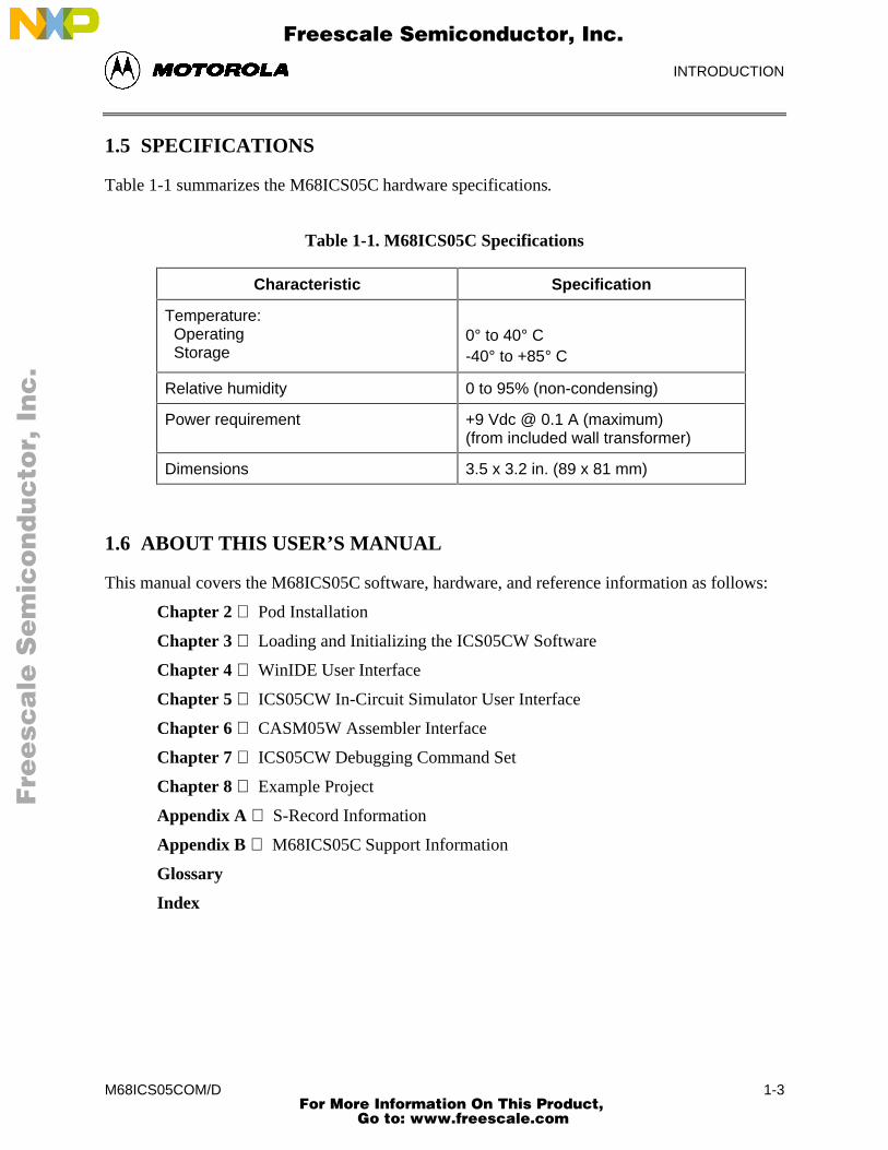
1.5 SPECIFICATIONS
Table 1-1 summarizes the M68ICS05C hardware specifications.
Table 1-1. M68ICS05C Specifications
Characteristic Specification
Temperature: Operating Storage
0° to 40° C-40° to +85° C
Relative humidity 0 to 95% (non-condensing)
Power requirement +9 Vdc @ 0.1 A (maximum)(from included wall transformer)
Dimensions 3.5 x 3.2 in. (89 x 81 mm)
1.6 ABOUT THIS USER’S MANUAL
This manual covers the M68ICS05C software, hardware, and reference information as follows:
Chapter 2 Pod Installation
Chapter 3 Loading and Initializing the ICS05CW Software
Chapter 4 WinIDE User Interface
Chapter 5 ICS05CW In-Circuit Simulator User Interface
Chapter 6 CASM05W Assembler Interface
Chapter 7 ICS05CW Debugging Command Set
Chapter 8 Example Project
Appendix A S-Record Information
Appendix B M68ICS05C Support Information
Glossary
Index
Fre
esc
ale
Se
mic
on
du
cto
r, I
Freescale Semiconductor, Inc.
For More Information On This Product, Go to: www.freescale.com
nc
...
INTRODUCTION
M68ICS05COM/D1-4
NOTE
The procedural instructions in this user’s manual assume that youare familiar with the Windows interface and selection procedures.
Figures in this manual show ICS05CW windows and dialog boxesas they appear in the Windows 95 environment.
1.7 QUICK START INSTRUCTIONS
The following instructions summarize the hardware and software installation instructions ofChapters 2 and 3.
If you are experienced in installing Motorola or other development tools, follow these steps.
• Install the ICS05CW software: follow the instructions on the diskette label to runthe ICS05CW Setup program. During installation, follow the instructions in theinstallation wizard: choose the Typical Install option to install the files to your harddisk, or choose the Compact Install option to copy the files onto another diskette.
• Connect the M68ICS05C pod: connect the M68ICS05C pod to the host PC’s serialport using the included cable. Plug the cable into the pod connector P2.
• Supply power to the M68ICS05C pod: connect the wall-mounted transformer’scircular connector to the connector on the left side of the pod, next to the serialconnector.
• Start the WinIDE editor and open the project files: Double click the WinIDE icon.From the WinIDE Environment menu, choose the Open Project option, and choose aproject file from the Specify project file to open dialog. If no project file exists,choose the New option from the File menu to create a new project file. Paragraph 8.3gives additional information about setting up a sample project.
• Configure the environment for the ICS05CW software components: from theWinIDE Environment menu, select the Setup Environment option to open theEnvironment Settings dialog and make the following changes:
− Click on the EXE1 Debugger tab to bring the tab (Figure 1-1) to the front. Setthe executable type, path and filename, command line options (includingoptional switches, filenames, or port settings), and other options for theICS05CW debugger application.
Fre
esc
ale
Se
mic
on
du
cto
r, I
Freescale Semiconductor, Inc.
For More Information On This Product, Go to: www.freescale.com
nc
...
INTRODUCTION
M68ICS05COM/D 1-5
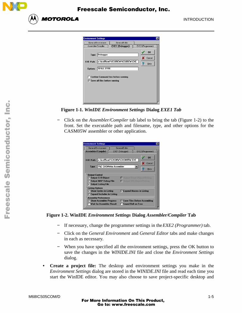
Figure 1-1. WinIDE Environment Settings Dialog EXE1 Tab
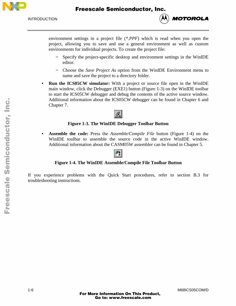
− Click on the Assembler/Compiler tab label to bring the tab (Figure 1-2) to thefront. Set the executable path and filename, type, and other options for theCASM05W assembler or other application.
Figure 1-2. WinIDE Environment Settings Dialog Assembler/Compiler Tab
− If necessary, change the programmer settings in the EXE2 (Programmer) tab.
− Click on the General Environment and General Editor tabs and make changesin each as necessary.
− When you have specified all the environment settings, press the OK button tosave the changes in the WINIDE.INI file and close the Environment Settingsdialog.
• Create a project file: The desktop and environment settings you make in theEnvironment Settings dialog are stored in the WINIDE.INI file and read each time youstart the WinIDE editor. You may also choose to save project-specific desktop and
Fre
esc
ale
Se
mic
on
du
cto
r, I
Freescale Semiconductor, Inc.
For More Information On This Product, Go to: www.freescale.com
nc
...
INTRODUCTION
M68ICS05COM/D1-6
environment settings in a project file (*.PPF) which is read when you open theproject, allowing you to save and use a general environment as well as customenvironments for individual projects. To create the project file:
− Specify the project-specific desktop and environment settings in the WinIDEeditor.
− Choose the Save Project As option from the WinIDE Environment menu toname and save the project to a directory folder.
• Run the ICS05CW simulator: With a project or source file open in the WinIDEmain window, click the Debugger (EXE1) button (Figure 1-3) on the WinIDE toolbarto start the ICS05CW debugger and debug the contents of the active source window.Additional information about the ICS05CW debugger can be found in Chapter 6 andChapter 7.
Figure 1-3. The WinIDE Debugger Toolbar Button
• Assemble the code: Press the Assemble/Compile File button (Figure 1-4) on theWinIDE toolbar to assemble the source code in the active WinIDE window.Additional information about the CASM05W assembler can be found in Chapter 5.
Figure 1-4. The WinIDE Assemble/Compile File Toolbar Button
If you experience problems with the Quick Start procedures, refer to section B.3 fortroubleshooting instructions.
Fre
esc
ale
Se
mic
on
du
cto
r, I
Freescale Semiconductor, Inc.
For More Information On This Product, Go to: www.freescale.com
nc
...
POD INSTALLATION
M68ICS05COM/D 2-1
CHAPTER 2
POD INSTALLATION
2.1 OVERVIEW
This chapter explains how to install the hardware components of the M68ICS05C in-circuitsimulator on your host PC in both interactive and standalone modes.
When the M68ICS05C pod is connected to the serial port of a host PC, you can use the actualinputs and outputs of your target system during simulation of your source code. When the pod isnot connected to the PC, you can use the ICS05CW software as a standalone simulator.
2.2 INSTALLING THE M68ICS05C POD
Before beginning, locate these pod components:
• Hardware reset switch S3
• Power On switch S1
• 9-pin RS-232 serial connector P2
• 9 Volt Input Circular connector P1
To install the M68ICS05C Pod:
1. Connect the M68ICS05C pod to the serial port of your computer: attach the supplied9-pin serial cable to the connector on the M68ICS05C board and attach the other endto the host PC’s serial port.
2. Connect the 9-volt power supply: attach the power supply plug to the circular powerconnector on the M68ICS05C pod and plug the power supply into a surge protectiondevice or wall outlet.
3. To run the ICS05CW software with actual input and output from the target device,connect the M68ICS05C pod to the 40-pin DIP socket on the target board using the40-pin ribbon cable included in the M68ICS05C kit. When this connection isestablished and the pod and target system are started up, the target system willprovide inputs to and accept output from the ICS05CW software.
Fre
esc
ale
Se
mic
on
du
cto
r, I
Freescale Semiconductor, Inc.
For More Information On This Product, Go to: www.freescale.com
nc
...
POD INSTALLATION
M68ICS05COM/D2-2
Fre
esc
ale
Se
mic
on
du
cto
r, I
Freescale Semiconductor, Inc.
For More Information On This Product, Go to: www.freescale.com
nc
...
SOFTWARE INSTALLATION AND INITIALIZATION
M68ICS05COM/D 3-1
CHAPTER 3
SOFTWARE INSTALLATION AND INITIALIZATION
3.1 OVERVIEW
This chapter how to install and initialize the ICS05CW software.
3.2 THE ICS05CW SOFTWARE COMPONENTS
The ICS05CW software consists of the following components:
• WINIDE.EXE: the Windows Integrated Development Environment editor
• CASM05W.EXE: the 68HC05 Cross Assembler
• ICS05CW.EXE: the in-circuit Simulator, optimized for the HC05Cx-family Motorolamicrocontrollers
3.2.1 The WinIDE Editor
The WinIDE editor is a text editing application that lets you use several different programs fromwithin a single development environment. Use the WinIDE editor to edit source code, launch avariety of compatible assemblers, compilers, debuggers, or programmers, and configure theenvironment to read and display errors from such programs.
If you select error detection options in the Environment Settings dialog, the WinIDE editor willhighlight errors in the source code, and display the error messages from the compiler orassembler in the editor.
To debug source code in the WinIDE code window, load compatible source-level map files. Youcan configure the CASM05W to produce such map files as an output.
Because the WinIDE editor is modular, you may, for example, choose to substitute a third partyC-compiler or other assembler for the CASM05W cross assembler provided in the toolkit.
3.2.2 CASM05W
The CASM05W is a cross assembler that creates Motorola S19 object files and MAP files fromassembly files containing 68HC05 instructions.
Fre
esc
ale
Se
mic
on
du
cto
r, I
Freescale Semiconductor, Inc.
For More Information On This Product, Go to: www.freescale.com
nc
...
SOFTWARE INSTALLATION AND INITIALIZATION
M68ICS05COM/D3-2
The CASM05W assembler has the same functionality as the DOS version of the assembler,optimized to take advantage of the Windows graphical environment. Using the assembler inconjunction with the WinIDE editor, you can edit standard ASCII files (such as the .ASMassembly files), and use menu options and toolbar buttons to call other customized assemblers,compilers, or debuggers. The resulting environment can allow assembled files to be downloadedand tested while the original source code is modified and assembled, all without leaving theWinIDE editing environment.
Paragraph 5-5 gives additional information about assembler options and how to use them.
3.2.3 ICS05CW
The ICS05CW is a simulator for HC705C series microcontrollers that can get inputs and outputs(I/O) for the device when the external M68ICS05C pod is attached to the host computer. If youwant to use I/O from your own target board, you can attach the M68ICS05C pod to your boardthrough the extension cable that comes with the toolkit. You can also program HC05C devicesusing the ICS05C board and ICS05CW software.
You can start or move to the ICS05CW in-circuit simulator software from the WinIDE editor.The ICS05CW software can also be started using standard Windows techniques and runindependently of the WinIDE editor.
The ICS05CW simulator accepts standard Motorola S19 object code files as input for object codesimulation and debugging. If you are using a third party assembly- or C-language compiler, thecompiler must be capable of producing source-level map files to allow source-level debugging.
3.3 INSTALLING THE ICS05CW SOFTWARE
The ICS05CW software is supplied on two 3.5″ diskettes containing a setup program thatautomatically installs the software on your hard drive.
3.3.1 Installation Steps
To install the software on your host computer’s hard drive, follow these steps:
1. Insert the ICS05CW diskette into the 3.5-inch disk drive.
For Windows 3.x: in the Program Manager, select Run from the File menu.
For Windows 95: from the Start Menu, select the Run option.
2. In the Run dialog, enter Setup (or click the Browse button to select a different driveand/or directory) and press OK.
Fre
esc
ale
Se
mic
on
du
cto
r, I
Freescale Semiconductor, Inc.
For More Information On This Product, Go to: www.freescale.com
nc
...
SOFTWARE INSTALLATION AND INITIALIZATION
M68ICS05COM/D 3-3
3. In the ICS05CW Microsoft Setup Wizard, follow the instructions that appear on thescreen.
NOTE
Select either the Typical Installation type to install the files to yourhard disk, or choose Compact Installation to copy the files toanother diskette.
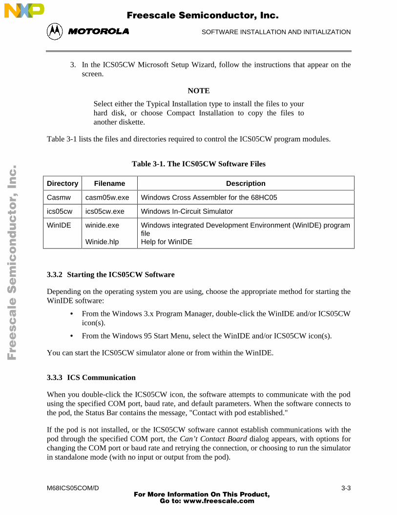
Table 3-1 lists the files and directories required to control the ICS05CW program modules.
Table 3-1. The ICS05CW Software Files
Directory Filename Description
Casmw casm05w.exe Windows Cross Assembler for the 68HC05
ics05cw ics05cw.exe Windows In-Circuit Simulator
WinIDE winide.exe
Winide.hlp
Windows integrated Development Environment (WinIDE) programfileHelp for WinIDE
3.3.2 Starting the ICS05CW Software
Depending on the operating system you are using, choose the appropriate method for starting theWinIDE software:
• From the Windows 3.x Program Manager, double-click the WinIDE and/or ICS05CWicon(s).
• From the Windows 95 Start Menu, select the WinIDE and/or ICS05CW icon(s).
You can start the ICS05CW simulator alone or from within the WinIDE.
3.3.3 ICS Communication
When you double-click the ICS05CW icon, the software attempts to communicate with the podusing the specified COM port, baud rate, and default parameters. When the software connects tothe pod, the Status Bar contains the message, "Contact with pod established."
If the pod is not installed, or the ICS05CW software cannot establish communications with thepod through the specified COM port, the Can’t Contact Board dialog appears, with options forchanging the COM port or baud rate and retrying the connection, or choosing to run the simulatorin standalone mode (with no input or output from the pod).
Fre
esc
ale
Se
mic
on
du
cto
r, I
Freescale Semiconductor, Inc.
For More Information On This Product, Go to: www.freescale.com
nc
...
SOFTWARE INSTALLATION AND INITIALIZATION
M68ICS05COM/D3-4
NOTE
The COM port assignment defaults to COM 1 unless you specifyanother port in the startup command.
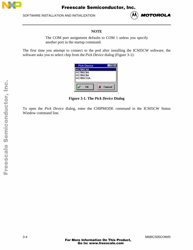
The first time you attempt to connect to the pod after installing the ICS05CW software, thesoftware asks you to select chip from the Pick Device dialog (Figure 3-1):
.
Figure 3-1. The Pick Device Dialog
To open the Pick Device dialog, enter the CHIPMODE command in the ICS05CW StatusWindow command line.
Fre
esc
ale
Se
mic
on
du
cto
r, I
Freescale Semiconductor, Inc.
For More Information On This Product, Go to: www.freescale.com
nc
...
WinIDE USER INTERFACE
M68ICS05COM/D 4-1
CHAPTER 4THE WinIDE USER INTERFACE
4.1 OVERVIEW
This chapter is an overview of the WinIDE windows, menus, toolbars, dialogs, options, andprocedures for using each.
4.2 THE WINDOWS INTEGRATED DEVELOPMENT ENVIRONMENT
The Windows Integrated Development Environment (the WinIDE editor) is a graphical interfacefor editing, compiling, assembling, and debugging source code for embedded systems using theM68ICS05C In-Circuit Simulator.
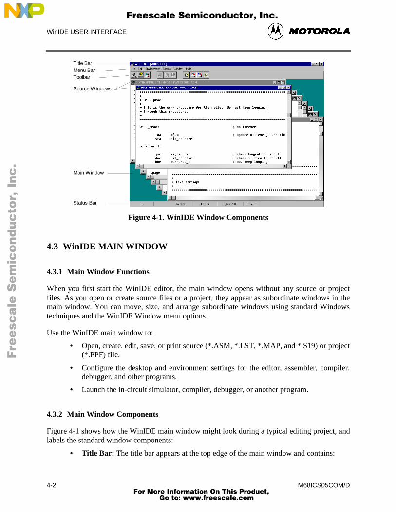
The WinIDE interface consists of standard Windows title and menu bars, a WinIDE toolbar, amain window containing any open source or project file windows, and a status bar. The WinIDEcomponents are labeled in Figure 4-1 and described in paragraph 4.3.2.
Fre
esc
ale
Se
mic
on
du
cto
r, I
Freescale Semiconductor, Inc.
For More Information On This Product, Go to: www.freescale.com
nc
...
WinIDE USER INTERFACE
M68ICS05COM/D4-2
Title Bar
Source Windows
Main Window
Menu BarToolbar
Status Bar
Figure 4-1. WinIDE Window Components
4.3 WinIDE MAIN WINDOW
4.3.1 Main Window Functions
When you first start the WinIDE editor, the main window opens without any source or projectfiles. As you open or create source files or a project, they appear as subordinate windows in themain window. You can move, size, and arrange subordinate windows using standard Windowstechniques and the WinIDE Window menu options.
Use the WinIDE main window to:
• Open, create, edit, save, or print source (*.ASM, *.LST, *.MAP, and *.S19) or project(*.PPF) file.
• Configure the desktop and environment settings for the editor, assembler, compiler,debugger, and other programs.
• Launch the in-circuit simulator, compiler, debugger, or another program.
4.3.2 Main Window Components
Figure 4-1 shows how the WinIDE main window might look during a typical editing project, andlabels the standard window components:
• Title Bar: The title bar appears at the top edge of the main window and contains:
Fre
esc
ale
Se
mic
on
du
cto
r, I
Freescale Semiconductor, Inc.
For More Information On This Product, Go to: www.freescale.com
nc
...
WinIDE USER INTERFACE
M68ICS05COM/D 4-3
− The application title,
− The name of the target microcomputer application for which you are editingsource code,
− The object file or files, if any (usually truncated),
− Windows control buttons for closing, minimizing or maximizing the window.
• Menu Bar: The menu bar appears immediately below the title bar and contains thenames of the WinIDE menus.
• Toolbar: The WinIDE toolbar appears just below the menu bar and contains shortcutbuttons for frequently used menu options.
• Main Window: The main window area is the inside portion of the main windowwhich contains the open subordinate windows that you can resize, reposition,minimize, or maximize using standard Windows techniques or Window menuoptions.
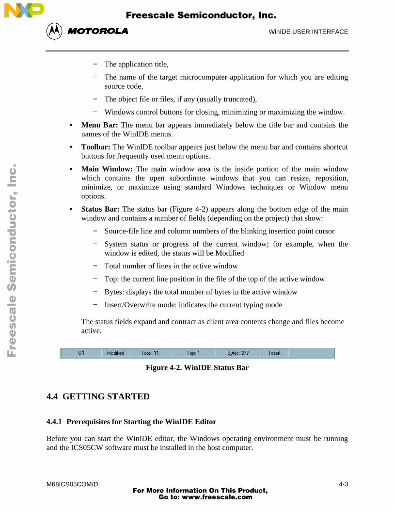
• Status Bar: The status bar (Figure 4-2) appears along the bottom edge of the mainwindow and contains a number of fields (depending on the project) that show:
− Source-file line and column numbers of the blinking insertion point cursor
− System status or progress of the current window; for example, when thewindow is edited, the status will be Modified
− Total number of lines in the active window
− Top: the current line position in the file of the top of the active window
− Bytes: displays the total number of bytes in the active window
− Insert/Overwrite mode: indicates the current typing mode
The status fields expand and contract as client area contents change and files becomeactive.
Figure 4-2. WinIDE Status Bar
4.4 GETTING STARTED
4.4.1 Prerequisites for Starting the WinIDE Editor
Before you can start the WinIDE editor, the Windows operating environment must be runningand the ICS05CW software must be installed in the host computer.
Fre
esc
ale
Se
mic
on
du
cto
r, I
Freescale Semiconductor, Inc.
For More Information On This Product, Go to: www.freescale.com
nc
...
WinIDE USER INTERFACE
M68ICS05COM/D4-4
Remember that for the M68ICS05C to run in simulation mode, the asynchronouscommunications cable must connect the M68ICS05C pod on the platform board to the hostcomputer, and the power to the M68ICS05C pod must be on.
4.4.2 Starting the WinIDE Editor
To start the editor, select the WinIDE icon by double-clicking the ICS05CW Program Groupicon in the Windows 3.1 Program Manager or by selecting the icon from the Windows 95 Startmenu.
4.4.3 Opening Source Files
When the WinIDE editor opens, the main window is empty. To build the environment for yourproject, choose the Open option from the File menu (or click the File button on the WinIDEtoolbar). In the Open File dialog, choose the files that will make up your project:
1. Select the drive containing the files from the Drives list.
2. Select the directory folder containing the files from the Folders list.
3. You may use the Filename text box to specify a filename or a wildcard/ extension tofilter the list of filenames (or choose a file type from the List files of type list). Thedefault file type is .ASM, but you can also choose:
*.c ( source code files)
*.lst (listing files)
*.txt (text files)
*.* (all files)
When all of the project files have been selected, click the OK button to open the files in theWinIDE main window.
4.4.4 Navigating in the WinIDE Editor
To navigate among subordinate windows:
To navigate among the several sub-windows in which your project files are displayed in theWinIDE main window:
• Choose the subordinate window’s filename from the Window menu or click on thefile’s title bar to bring it to the front of the cascaded stack.
• If you have a large screen or a few project files, you may choose the Tile option fromthe Window menu to lay out all of the sub-windows so that all are visible, or choose
Fre
esc
ale
Se
mic
on
du
cto
r, I
Freescale Semiconductor, Inc.
For More Information On This Product, Go to: www.freescale.com
nc
...
WinIDE USER INTERFACE
M68ICS05COM/D 4-5
the Cascade option to arrange all windows so that only the top window is entirelyvisible.
• Regardless of how you arrange the windows, the title bar of all windows are visible.
To move between the WinIDE editor and the ICS05CW simulator:
• From the WinIDE editor, click the External Program 1 toolbar button to switchto the in-circuit simulator or the application which you have specified as the debuggeror other external program to use.
• From ICS05CW, click the Back to Editor toolbar button to toggle back to theeditor.
4.4.5 Using Markers
Markers provide a convenient way to mark multiple points in a file for navigating betweenfrequently visited locations while you are editing. You can set as many as 10 markers in sourcefiles in the WinIDE editor. A marker appears in the file as a small button labeled with the markernumber.
When you save the project, the WinIDE editor saves the markers for all open edit files as well, sothat when you open the project again, the markers are still set.
To set a marker anywhere in the file:
1. Place the cursor on the line where you want the marker to be.
2. Press CNTL + SHIFT + N, where N is a value from 0 to 9 indicating the markernumber. A marker appears at the far left of the line.
To move to a marker, press CNTL + N, where N is denotes a marker number between 0 and 9.This feature is useful if you are editing a large file.
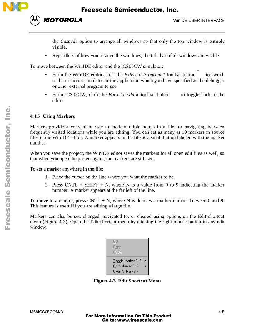
Markers can also be set, changed, navigated to, or cleared using options on the Edit shortcutmenu (Figure 4-3). Open the Edit shortcut menu by clicking the right mouse button in any editwindow.
Figure 4-3. Edit Shortcut Menu
Fre
esc
ale
Se
mic
on
du
cto
r, I
Freescale Semiconductor, Inc.
For More Information On This Product, Go to: www.freescale.com
nc
...
WinIDE USER INTERFACE
M68ICS05COM/D4-6
To set or clear a marker using the Edit shortcut menu options:
1. With the cursor in any editing window, click the right mouse button to open theshortcut menu.
2. Position the cursor on the line where the marker should appear. Click the right mousebutton to display the shortcut menu.
3. Click the Toggle Marker 0-9 option to open the list of markers.
4. Click once on the marker to toggle. When the marker number is checked, it is toggledon; when the marker number is unchecked, it is toggled off.
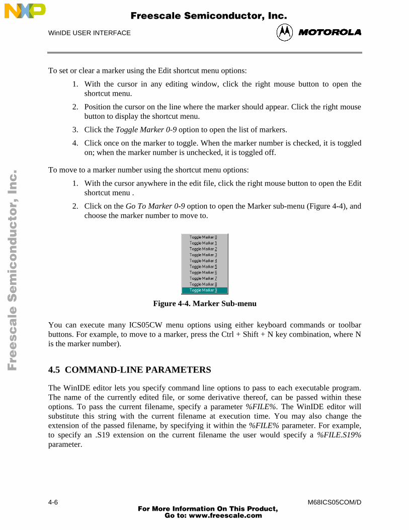
To move to a marker number using the shortcut menu options:
1. With the cursor anywhere in the edit file, click the right mouse button to open the Editshortcut menu .
2. Click on the Go To Marker 0-9 option to open the Marker sub-menu (Figure 4-4), andchoose the marker number to move to.
Figure 4-4. Marker Sub-menu
You can execute many ICS05CW menu options using either keyboard commands or toolbarbuttons. For example, to move to a marker, press the Ctrl + Shift + N key combination, where Nis the marker number).
4.5 COMMAND-LINE PARAMETERS
The WinIDE editor lets you specify command line options to pass to each executable program.The name of the currently edited file, or some derivative thereof, can be passed within theseoptions. To pass the current filename, specify a parameter %FILE%. The WinIDE editor willsubstitute this string with the current filename at execution time. You may also change theextension of the passed filename, by specifying it within the %FILE% parameter. For example,to specify an .S19 extension on the current filename the user would specify a %FILE.S19%parameter.
Fre
esc
ale
Se
mic
on
du
cto
r, I
Freescale Semiconductor, Inc.
For More Information On This Product, Go to: www.freescale.com
nc
...
WinIDE USER INTERFACE
M68ICS05COM/D 4-7
For example, if the current filename being edited is MYPDA.ASM:
Parameters specifiedParameters passed to
program
%FILE% S L D MYPDA.ASM S L D
%FILE.S19% 1 @2 MYPDA.S19 1 @2
Although it is by default the currently edited filename that is used in the %FILE% parametersubstitution, the environment can be configured always to pass the same filename. Do this bychecking the Main File option in the Environment Settings dialog’s General Options tab. Thistechnique is useful if you want to pass a specific filename to the external program without regardto what is being edited.
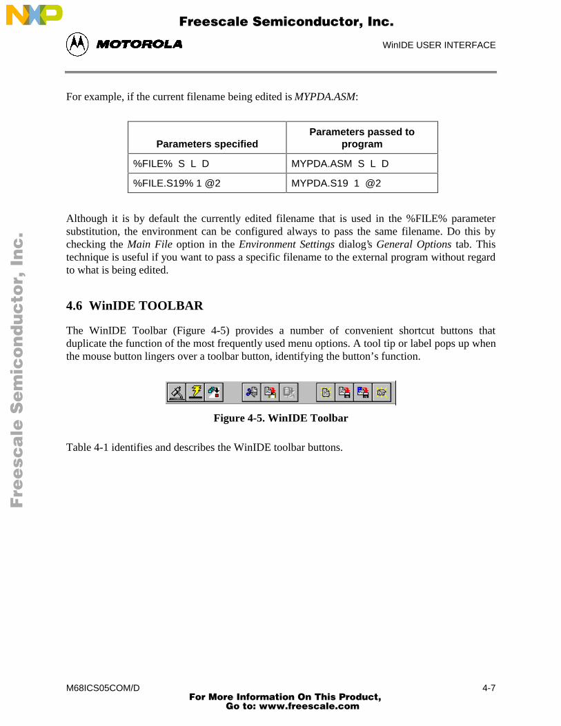
4.6 WinIDE TOOLBAR
The WinIDE Toolbar (Figure 4-5) provides a number of convenient shortcut buttons thatduplicate the function of the most frequently used menu options. A tool tip or label pops up whenthe mouse button lingers over a toolbar button, identifying the button’s function.
Figure 4-5. WinIDE Toolbar
Table 4-1 identifies and describes the WinIDE toolbar buttons.
Fre
esc
ale
Se
mic
on
du
cto
r, I
Freescale Semiconductor, Inc.
For More Information On This Product, Go to: www.freescale.com
nc
...
WinIDE USER INTERFACE
M68ICS05COM/D4-8
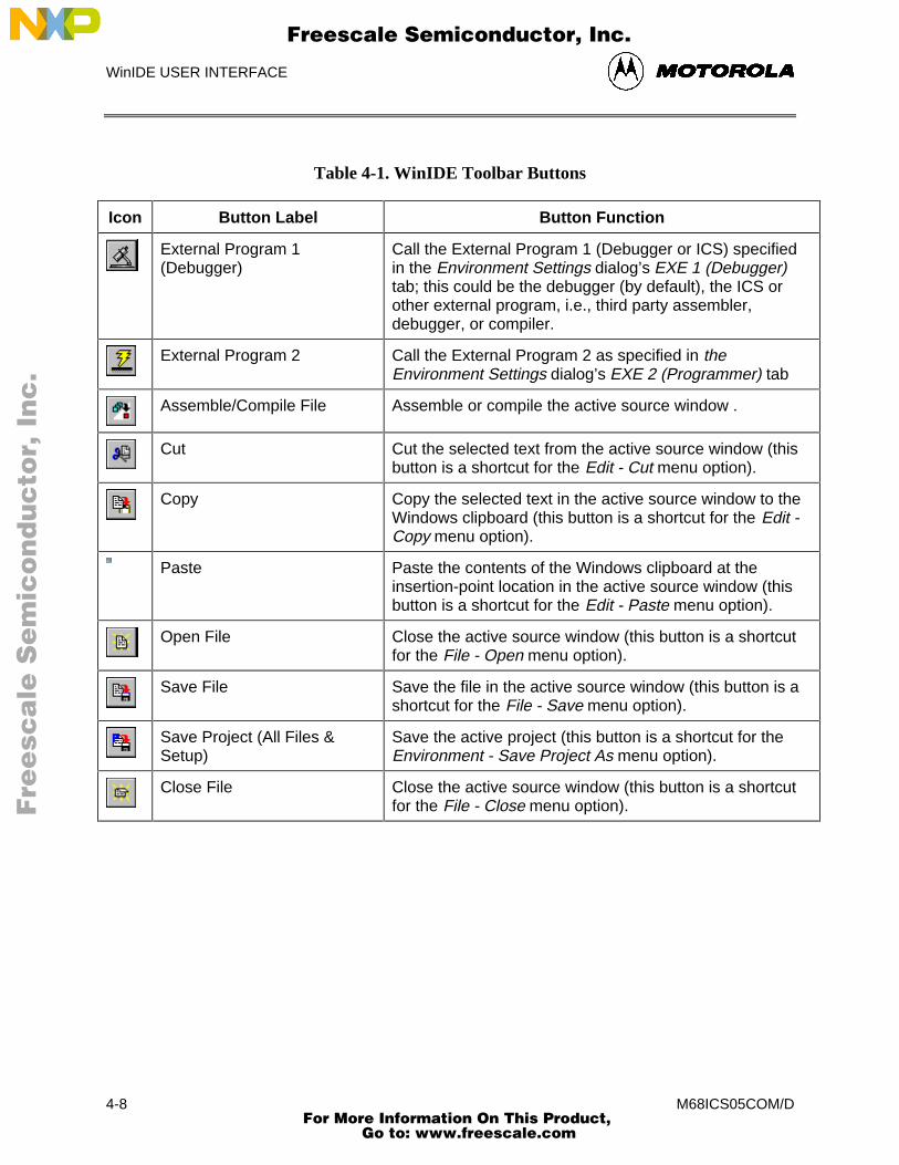
Table 4-1. WinIDE Toolbar Buttons
Icon Button Label Button Function
External Program 1(Debugger)
Call the External Program 1 (Debugger or ICS) specifiedin the Environment Settings dialog’s EXE 1 (Debugger)tab; this could be the debugger (by default), the ICS orother external program, i.e., third party assembler,debugger, or compiler.
External Program 2 Call the External Program 2 as specified in theEnvironment Settings dialog’s EXE 2 (Programmer) tab
Assemble/Compile File Assemble or compile the active source window .
Cut Cut the selected text from the active source window (thisbutton is a shortcut for the Edit - Cut menu option).
Copy Copy the selected text in the active source window to theWindows clipboard (this button is a shortcut for the Edit -Copy menu option).
Paste Paste the contents of the Windows clipboard at theinsertion-point location in the active source window (thisbutton is a shortcut for the Edit - Paste menu option).
Open File Close the active source window (this button is a shortcutfor the File - Open menu option).
Save File Save the file in the active source window (this button is ashortcut for the File - Save menu option).
Save Project (All Files &Setup)
Save the active project (this button is a shortcut for theEnvironment - Save Project As menu option).
Close File Close the active source window (this button is a shortcutfor the File - Close menu option).
Fre
esc
ale
Se
mic
on
du
cto
r, I
Freescale Semiconductor, Inc.
For More Information On This Product, Go to: www.freescale.com
nc
...
WinIDE USER INTERFACE
M68ICS05COM/D 4-9
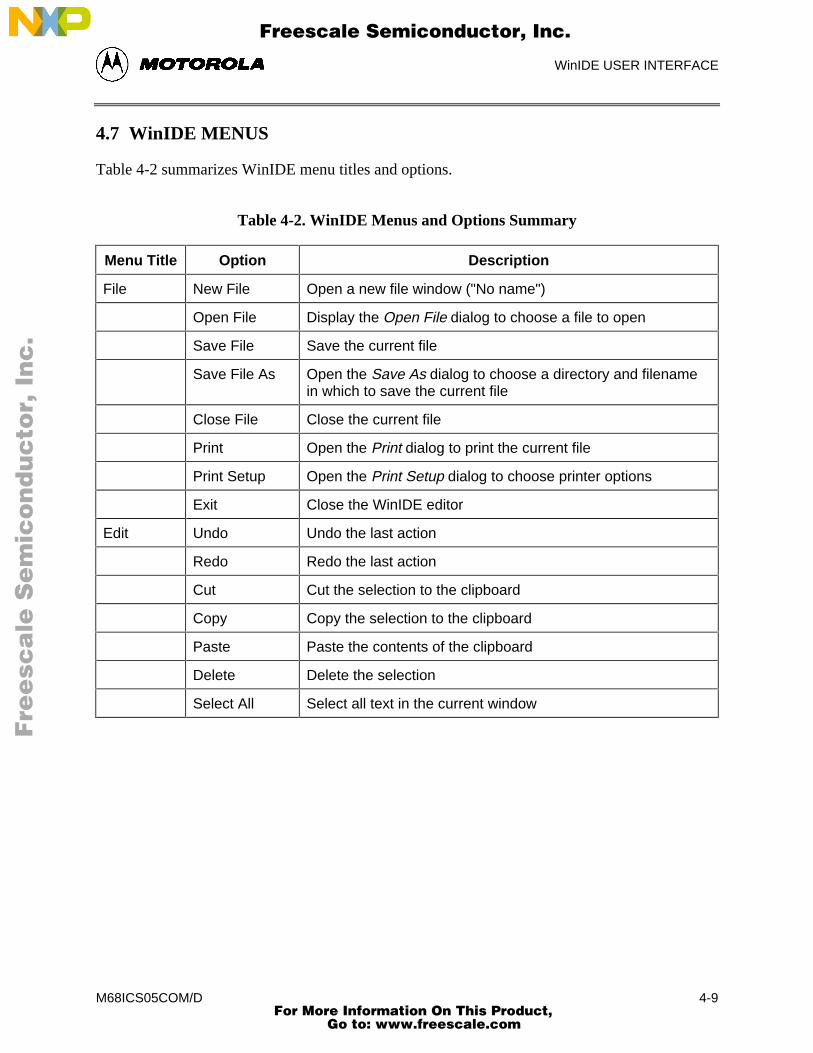
4.7 WinIDE MENUS
Table 4-2 summarizes WinIDE menu titles and options.
Table 4-2. WinIDE Menus and Options Summary
Menu Title Option Description
File New File Open a new file window ("No name")
Open File Display the Open File dialog to choose a file to open
Save File Save the current file
Save File As Open the Save As dialog to choose a directory and filenamein which to save the current file
Close File Close the current file
Print Open the Print dialog to print the current file
Print Setup Open the Print Setup dialog to choose printer options
Exit Close the WinIDE editor
Edit Undo Undo the last action
Redo Redo the last action
Cut Cut the selection to the clipboard
Copy Copy the selection to the clipboard
Paste Paste the contents of the clipboard
Delete Delete the selection
Select All Select all text in the current window
Fre
esc
ale
Se
mic
on
du
cto
r, I
Freescale Semiconductor, Inc.
For More Information On This Product, Go to: www.freescale.com
nc
...
WinIDE USER INTERFACE
M68ICS05COM/D4-10
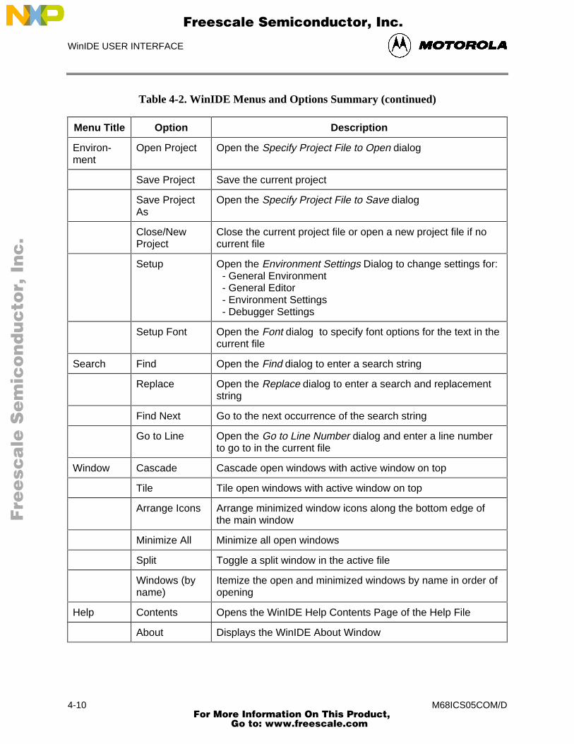
Table 4-2. WinIDE Menus and Options Summary (continued)
Menu Title Option Description
Environ-ment
Open Project Open the Specify Project File to Open dialog
Save Project Save the current project
Save ProjectAs
Open the Specify Project File to Save dialog
Close/NewProject
Close the current project file or open a new project file if nocurrent file
Setup Open the Environment Settings Dialog to change settings for: - General Environment - General Editor - Environment Settings - Debugger Settings
Setup Font Open the Font dialog to specify font options for the text in thecurrent file
Search Find Open the Find dialog to enter a search string
Replace Open the Replace dialog to enter a search and replacementstring
Find Next Go to the next occurrence of the search string
Go to Line Open the Go to Line Number dialog and enter a line numberto go to in the current file
Window Cascade Cascade open windows with active window on top
Tile Tile open windows with active window on top
Arrange Icons Arrange minimized window icons along the bottom edge ofthe main window
Minimize All Minimize all open windows
Split Toggle a split window in the active file
Windows (byname)
Itemize the open and minimized windows by name in order ofopening
Help Contents Opens the WinIDE Help Contents Page of the Help File
About Displays the WinIDE About Window
Fre
esc
ale
Se
mic
on
du
cto
r, I
Freescale Semiconductor, Inc.
For More Information On This Product, Go to: www.freescale.com
nc
...
WinIDE USER INTERFACE
M68ICS05COM/D 4-11
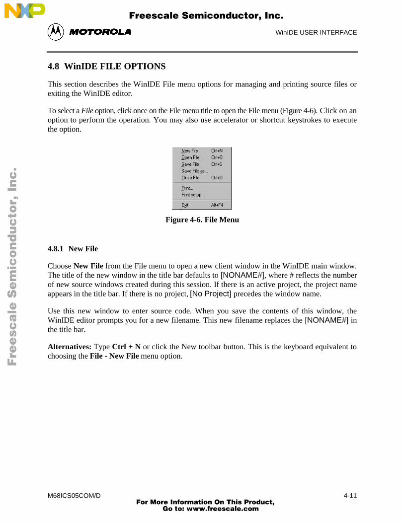
4.8 WinIDE FILE OPTIONS
This section describes the WinIDE File menu options for managing and printing source files orexiting the WinIDE editor.
To select a File option, click once on the File menu title to open the File menu (Figure 4-6). Click on anoption to perform the operation. You may also use accelerator or shortcut keystrokes to executethe option.
Figure 4-6. File Menu
4.8.1 New File
Choose New File from the File menu to open a new client window in the WinIDE main window.The title of the new window in the title bar defaults to [NONAME#], where # reflects the numberof new source windows created during this session. If there is an active project, the project nameappears in the title bar. If there is no project, [No Project] precedes the window name.
Use this new window to enter source code. When you save the contents of this window, theWinIDE editor prompts you for a new filename. This new filename replaces the [NONAME#] inthe title bar.
Alternatives: Type Ctrl + N or click the New toolbar button. This is the keyboard equivalent tochoosing the File - New File menu option.
Fre
esc
ale
Se
mic
on
du
cto
r, I
Freescale Semiconductor, Inc.
For More Information On This Product, Go to: www.freescale.com
nc
...
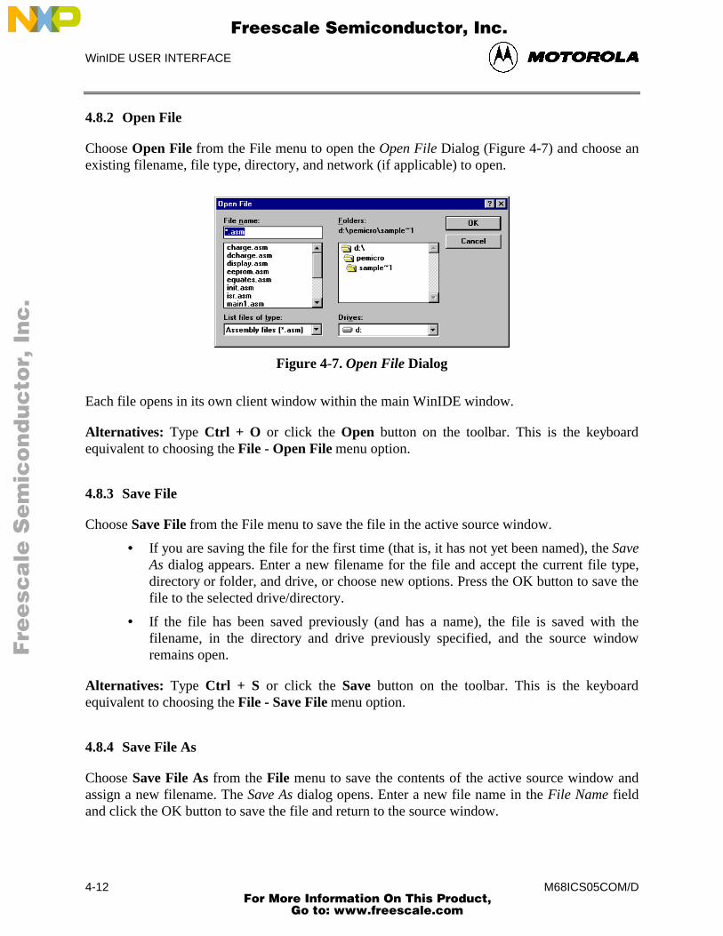
WinIDE USER INTERFACE
M68ICS05COM/D4-12
4.8.2 Open File
Choose Open File from the File menu to open the Open File Dialog (Figure 4-7) and choose anexisting filename, file type, directory, and network (if applicable) to open.
Figure 4-7. Open File Dialog
Each file opens in its own client window within the main WinIDE window.
Alternatives: Type Ctrl + O or click the Open button on the toolbar. This is the keyboardequivalent to choosing the File - Open File menu option.
4.8.3 Save File
Choose Save File from the File menu to save the file in the active source window.
• If you are saving the file for the first time (that is, it has not yet been named), the SaveAs dialog appears. Enter a new filename for the file and accept the current file type,directory or folder, and drive, or choose new options. Press the OK button to save thefile to the selected drive/directory.
• If the file has been saved previously (and has a name), the file is saved with thefilename, in the directory and drive previously specified, and the source windowremains open.
Alternatives: Type Ctrl + S or click the Save button on the toolbar. This is the keyboardequivalent to choosing the File - Save File menu option.
4.8.4 Save File As
Choose Save File As from the File menu to save the contents of the active source window andassign a new filename. The Save As dialog opens. Enter a new file name in the File Name fieldand click the OK button to save the file and return to the source window.
Fre
esc
ale
Se
mic
on
du
cto
r, I
Freescale Semiconductor, Inc.
For More Information On This Product, Go to: www.freescale.com
nc
...
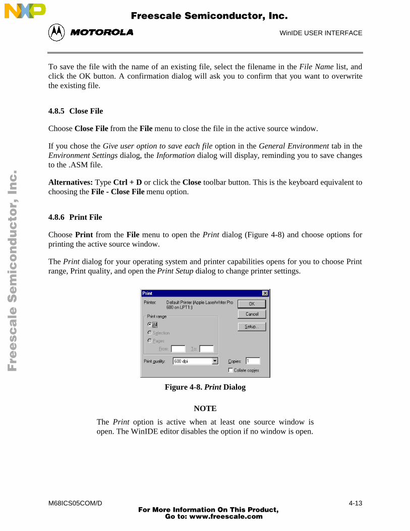
WinIDE USER INTERFACE
M68ICS05COM/D 4-13
To save the file with the name of an existing file, select the filename in the File Name list, andclick the OK button. A confirmation dialog will ask you to confirm that you want to overwritethe existing file.
4.8.5 Close File
Choose Close File from the File menu to close the file in the active source window.
If you chose the Give user option to save each file option in the General Environment tab in theEnvironment Settings dialog, the Information dialog will display, reminding you to save changesto the .ASM file.
Alternatives: Type Ctrl + D or click the Close toolbar button. This is the keyboard equivalent tochoosing the File - Close File menu option.
4.8.6 Print File
Choose Print from the File menu to open the Print dialog (Figure 4-8) and choose options forprinting the active source window.
The Print dialog for your operating system and printer capabilities opens for you to choose Printrange, Print quality, and open the Print Setup dialog to change printer settings.
Figure 4-8. Print Dialog
NOTE
The Print option is active when at least one source window isopen. The WinIDE editor disables the option if no window is open.
Fre
esc
ale
Se
mic
on
du
cto
r, I
Freescale Semiconductor, Inc.
For More Information On This Product, Go to: www.freescale.com
nc
...
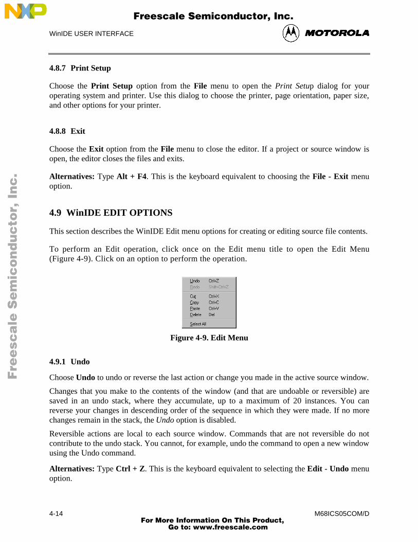
WinIDE USER INTERFACE
M68ICS05COM/D4-14
4.8.7 Print Setup
Choose the Print Setup option from the File menu to open the Print Setup dialog for youroperating system and printer. Use this dialog to choose the printer, page orientation, paper size,and other options for your printer.
4.8.8 Exit
Choose the Exit option from the File menu to close the editor. If a project or source window isopen, the editor closes the files and exits.
Alternatives: Type Alt + F4. This is the keyboard equivalent to choosing the File - Exit menuoption.
4.9 WinIDE EDIT OPTIONS
This section describes the WinIDE Edit menu options for creating or editing source file contents.
To perform an Edit operation, click once on the Edit menu title to open the Edit Menu(Figure 4-9). Click on an option to perform the operation.
Figure 4-9. Edit Menu
4.9.1 Undo
Choose Undo to undo or reverse the last action or change you made in the active source window.
Changes that you make to the contents of the window (and that are undoable or reversible) aresaved in an undo stack, where they accumulate, up to a maximum of 20 instances. You canreverse your changes in descending order of the sequence in which they were made. If no morechanges remain in the stack, the Undo option is disabled.
Reversible actions are local to each source window. Commands that are not reversible do notcontribute to the undo stack. You cannot, for example, undo the command to open a new windowusing the Undo command.
Alternatives: Type Ctrl + Z. This is the keyboard equivalent to selecting the Edit - Undo menuoption.
Fre
esc
ale
Se
mic
on
du
cto
r, I
Freescale Semiconductor, Inc.
For More Information On This Product, Go to: www.freescale.com
nc
...
WinIDE USER INTERFACE
M68ICS05COM/D 4-15
4.9.2 Redo
Choose Redo to restore the most recently undone action in the active window.
The Redo option restores actions undone or reversed by the Undo option, in ascending order, thatis, last action first. Reversible changes to the window’s contents accumulate in the window’sundo stack. Once a change has been reversed using the Undo option, the change can be reversed,using the Redo option When no more changes remain (that is, the top of the Redo stack isreached) the Redo option is disabled.
Some commands are not reversible: they do not contribute to the undo stack and therefore cannotbe redone. For instance, since reversible actions are local to each source window, opening a newwindow is an action that cannot be undone using the Undo command, or redone using the Redocommand.
NOTE
The Redo option is active only if you have used the Undo option tomodify the contents of the active source window.
Alternative: Type Shift + Ctrl + Z. This is the keyboard equivalent to selecting the Edit - Redomenu option.
4.9.3 Cut
Choose Cut from the Edit menu to cut the currently selected text from the active source windowand place it on the system clipboard.
NOTE
The Cut option is active only when you have selected text in theactive source window.
Alternative: Type Ctrl + X. This is the keyboard equivalent to selecting the Edit - Cut menuoption.
4.9.4 Copy
Choose Copy from the Edit menu to copy the selected text from the active source window to theWindows clipboard.
NOTE
The Copy option is available only if you have selected text in theactive source window.
Fre
esc
ale
Se
mic
on
du
cto
r, I
Freescale Semiconductor, Inc.
For More Information On This Product, Go to: www.freescale.com
nc
...
WinIDE USER INTERFACE
M68ICS05COM/D4-16
Alternatives: Type Ctrl +C or click the Copy toolbar button. This is the keyboard equivalent toselecting the Edit - Copy menu option.
4.9.5 Paste
Choose Paste from the Edit menu to paste the contents of the Windows clipboard into the activesource window at the insertion-point location.
Alternatives: Type Ctrl + V or click the Paste button on the toolbar. This is the keyboardequivalent to selecting the Edit - Paste menu option.
4.9.6 Delete
Choose Delete from the Edit menu to delete the selected text from the active source windowwithout placing it on the Windows clipboard. Text you delete using the Delete option can berestored only by using the Undo option.
Alternatives: Press the Delete key. This is the keyboard equivalent to selecting the Edit - Deletemenu option.
4.9.7 Select All
Choose Select All from the Edit menu to select all text in the active source window.
4.10 WinIDE ENVIRONMENT OPTIONS
This section describes the WinIDE Environment menu options for managing project information,and setting up environment and font settings for a project.
Environment settings represent the current environment and configuration information for theWinIDE editor. These settings are stored in the WINIDE.INI file, from which they are loadedeach time you start the editor, and saved each time you exit from the editor.
When you start the editor, the application opens the WINIDE.INI file and reads the projectinformation. If there is an open project, the project file’s environment settings are read and usedinstead. This lets you have different environment configurations for different projects.
Environment information stored in the WINIDE.INI file includes:
• If a project is open, its name
• Current font information
• Current source directory and project directory paths
Fre
esc
ale
Se
mic
on
du
cto
r, I
Freescale Semiconductor, Inc.
For More Information On This Product, Go to: www.freescale.com
nc
...
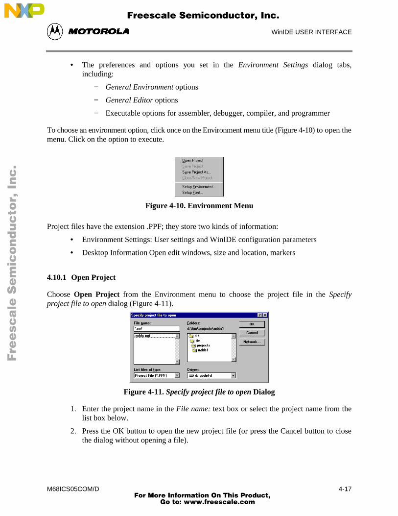
WinIDE USER INTERFACE
M68ICS05COM/D 4-17
• The preferences and options you set in the Environment Settings dialog tabs,including:
− General Environment options
− General Editor options
− Executable options for assembler, debugger, compiler, and programmer
To choose an environment option, click once on the Environment menu title (Figure 4-10) to open themenu. Click on the option to execute.
Figure 4-10. Environment Menu
Project files have the extension .PPF; they store two kinds of information:
• Environment Settings: User settings and WinIDE configuration parameters
• Desktop Information Open edit windows, size and location, markers
4.10.1 Open Project
Choose Open Project from the Environment menu to choose the project file in the Specifyproject file to open dialog (Figure 4-11).
Figure 4-11. Specify project file to open Dialog
1. Enter the project name in the File name: text box or select the project name from thelist box below.
2. Press the OK button to open the new project file (or press the Cancel button to closethe dialog without opening a file).
Fre
esc
ale
Se
mic
on
du
cto
r, I
Freescale Semiconductor, Inc.
For More Information On This Product, Go to: www.freescale.com
nc
...
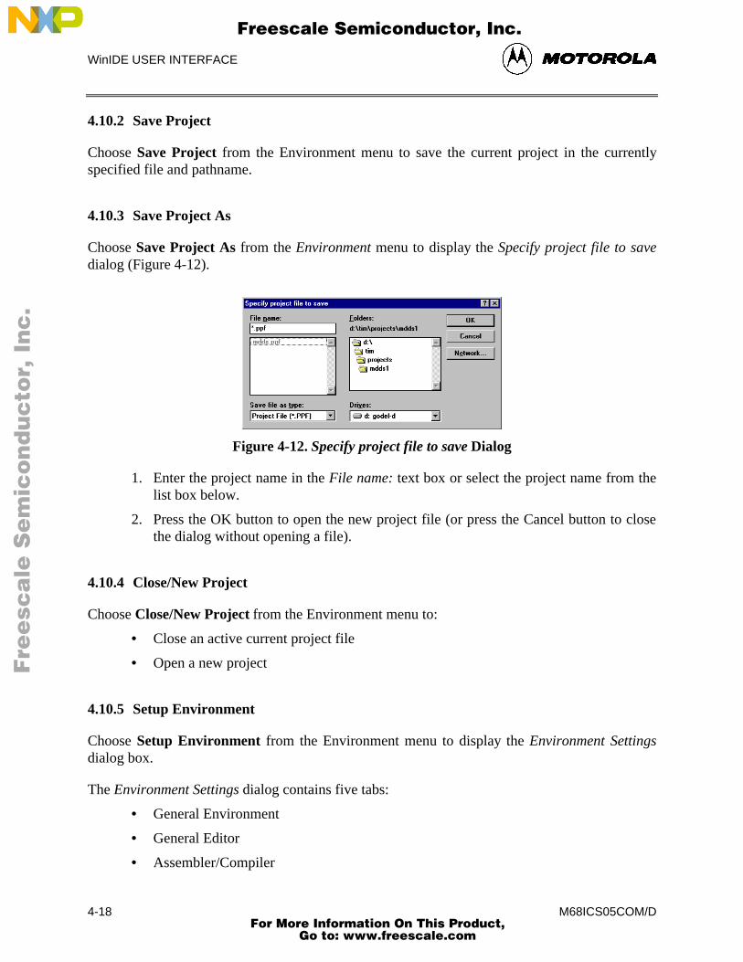
WinIDE USER INTERFACE
M68ICS05COM/D4-18
4.10.2 Save Project
Choose Save Project from the Environment menu to save the current project in the currentlyspecified file and pathname.
4.10.3 Save Project As
Choose Save Project As from the Environment menu to display the Specify project file to savedialog (Figure 4-12).
Figure 4-12. Specify project file to save Dialog
1. Enter the project name in the File name: text box or select the project name from thelist box below.
2. Press the OK button to open the new project file (or press the Cancel button to closethe dialog without opening a file).
4.10.4 Close/New Project
Choose Close/New Project from the Environment menu to:
• Close an active current project file
• Open a new project
4.10.5 Setup Environment
Choose Setup Environment from the Environment menu to display the Environment Settingsdialog box.
The Environment Settings dialog contains five tabs:
• General Environment
• General Editor
• Assembler/Compiler
Fre
esc
ale
Se
mic
on
du
cto
r, I
Freescale Semiconductor, Inc.
For More Information On This Product, Go to: www.freescale.com
nc
...
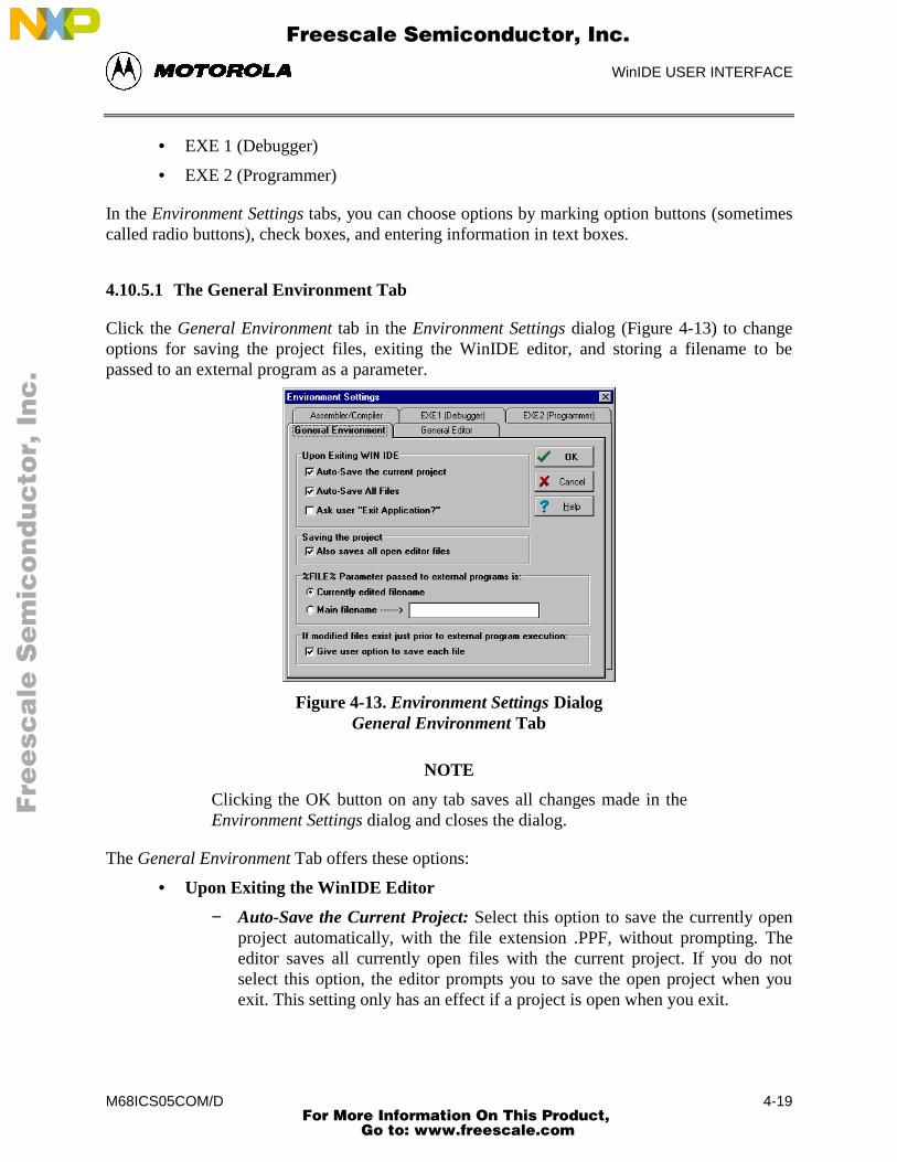
WinIDE USER INTERFACE
M68ICS05COM/D 4-19
• EXE 1 (Debugger)
• EXE 2 (Programmer)
In the Environment Settings tabs, you can choose options by marking option buttons (sometimescalled radio buttons), check boxes, and entering information in text boxes.
4.10.5.1 The General Environment Tab
Click the General Environment tab in the Environment Settings dialog (Figure 4-13) to changeoptions for saving the project files, exiting the WinIDE editor, and storing a filename to bepassed to an external program as a parameter.
Figure 4-13. Environment Settings DialogGeneral Environment Tab
NOTE
Clicking the OK button on any tab saves all changes made in theEnvironment Settings dialog and closes the dialog.
The General Environment Tab offers these options:
• Upon Exiting the WinIDE Editor
− Auto-Save the Current Project: Select this option to save the currently openproject automatically, with the file extension .PPF, without prompting. Theeditor saves all currently open files with the current project. If you do notselect this option, the editor prompts you to save the open project when youexit. This setting only has an effect if a project is open when you exit.
Fre
esc
ale
Se
mic
on
du
cto
r, I
Freescale Semiconductor, Inc.
For More Information On This Product, Go to: www.freescale.com
nc
...
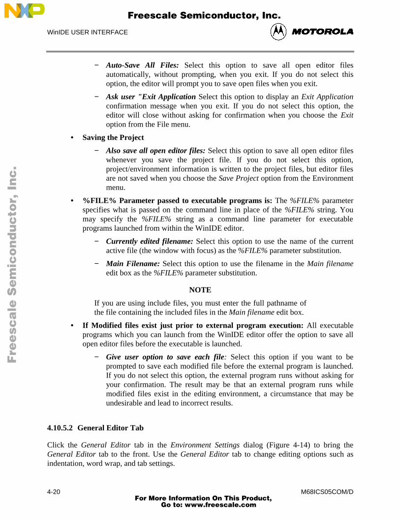
WinIDE USER INTERFACE
M68ICS05COM/D4-20
− Auto-Save All Files: Select this option to save all open editor filesautomatically, without prompting, when you exit. If you do not select thisoption, the editor will prompt you to save open files when you exit.
− Ask user "Exit Application Select this option to display an Exit Applicationconfirmation message when you exit. If you do not select this option, theeditor will close without asking for confirmation when you choose the Exitoption from the File menu.
• Saving the Project
− Also save all open editor files: Select this option to save all open editor fileswhenever you save the project file. If you do not select this option,project/environment information is written to the project files, but editor filesare not saved when you choose the Save Project option from the Environmentmenu.
• %FILE% Parameter passed to executable programs is: The %FILE% parameterspecifies what is passed on the command line in place of the %FILE% string. Youmay specify the %FILE% string as a command line parameter for executableprograms launched from within the WinIDE editor.
− Currently edited filename: Select this option to use the name of the currentactive file (the window with focus) as the %FILE% parameter substitution.
− Main Filename: Select this option to use the filename in the Main filenameedit box as the %FILE% parameter substitution.
NOTE
If you are using include files, you must enter the full pathname ofthe file containing the included files in the Main filename edit box.
• If Modified files exist just prior to external program execution: All executableprograms which you can launch from the WinIDE editor offer the option to save allopen editor files before the executable is launched.
− Give user option to save each file: Select this option if you want to beprompted to save each modified file before the external program is launched.If you do not select this option, the external program runs without asking foryour confirmation. The result may be that an external program runs whilemodified files exist in the editing environment, a circumstance that may beundesirable and lead to incorrect results.
4.10.5.2 General Editor Tab
Click the General Editor tab in the Environment Settings dialog (Figure 4-14) to bring theGeneral Editor tab to the front. Use the General Editor tab to change editing options such asindentation, word wrap, and tab settings.
Fre
esc
ale
Se
mic
on
du
cto
r, I
Freescale Semiconductor, Inc.
For More Information On This Product, Go to: www.freescale.com
nc
...
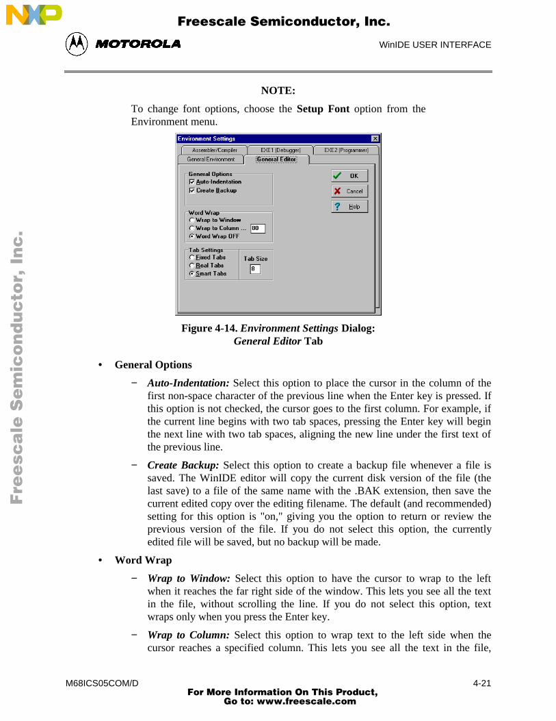
WinIDE USER INTERFACE
M68ICS05COM/D 4-21
NOTE:
To change font options, choose the Setup Font option from theEnvironment menu.
Figure 4-14. Environment Settings Dialog:General Editor Tab
• General Options
− Auto-Indentation: Select this option to place the cursor in the column of thefirst non-space character of the previous line when the Enter key is pressed. Ifthis option is not checked, the cursor goes to the first column. For example, ifthe current line begins with two tab spaces, pressing the Enter key will beginthe next line with two tab spaces, aligning the new line under the first text ofthe previous line.
− Create Backup: Select this option to create a backup file whenever a file issaved. The WinIDE editor will copy the current disk version of the file (thelast save) to a file of the same name with the .BAK extension, then save thecurrent edited copy over the editing filename. The default (and recommended)setting for this option is "on," giving you the option to return or review theprevious version of the file. If you do not select this option, the currentlyedited file will be saved, but no backup will be made.
• Word Wrap
− Wrap to Window: Select this option to have the cursor to wrap to the leftwhen it reaches the far right side of the window. This lets you see all the textin the file, without scrolling the line. If you do not select this option, textwraps only when you press the Enter key.
− Wrap to Column: Select this option to wrap text to the left side when thecursor reaches a specified column. This lets you see all the text in the file,
Fre
esc
ale
Se
mic
on
du
cto
r, I
Freescale Semiconductor, Inc.
For More Information On This Product, Go to: www.freescale.com
nc
...
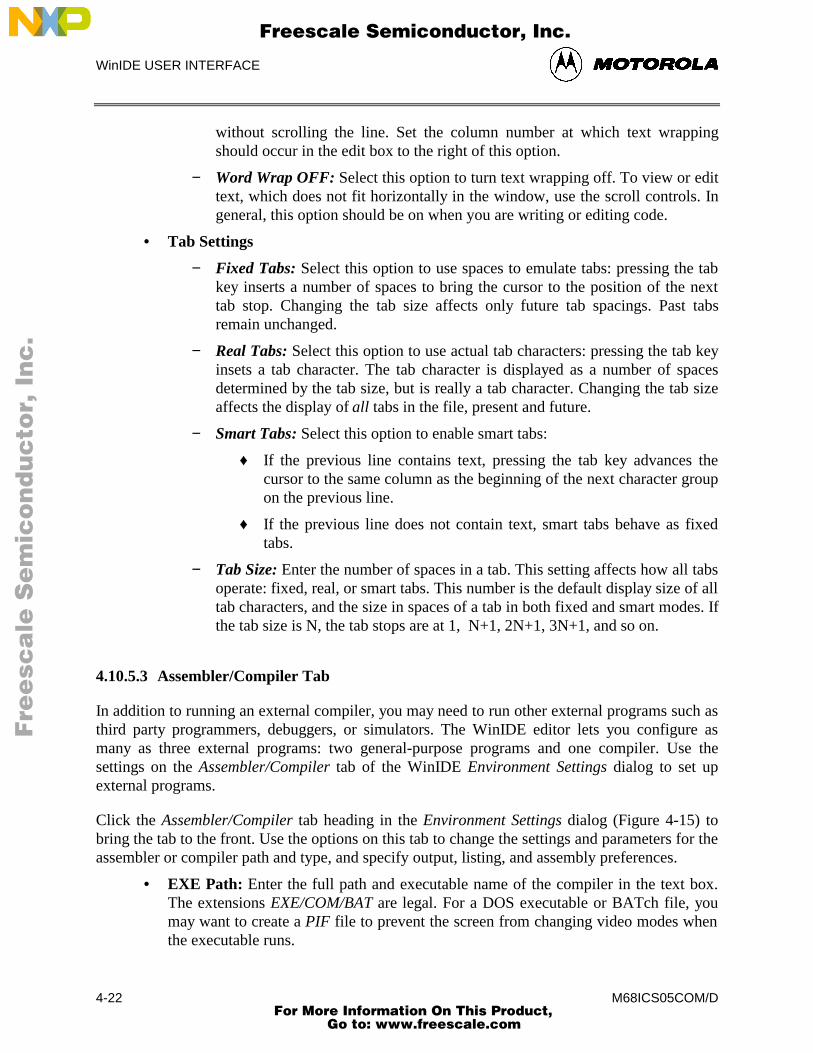
WinIDE USER INTERFACE
M68ICS05COM/D4-22
without scrolling the line. Set the column number at which text wrappingshould occur in the edit box to the right of this option.
− Word Wrap OFF: Select this option to turn text wrapping off. To view or edittext, which does not fit horizontally in the window, use the scroll controls. Ingeneral, this option should be on when you are writing or editing code.
• Tab Settings
− Fixed Tabs: Select this option to use spaces to emulate tabs: pressing the tabkey inserts a number of spaces to bring the cursor to the position of the nexttab stop. Changing the tab size affects only future tab spacings. Past tabsremain unchanged.
− Real Tabs: Select this option to use actual tab characters: pressing the tab keyinsets a tab character. The tab character is displayed as a number of spacesdetermined by the tab size, but is really a tab character. Changing the tab sizeaffects the display of all tabs in the file, present and future.
− Smart Tabs: Select this option to enable smart tabs:
♦ If the previous line contains text, pressing the tab key advances thecursor to the same column as the beginning of the next character groupon the previous line.
♦ If the previous line does not contain text, smart tabs behave as fixedtabs.
− Tab Size: Enter the number of spaces in a tab. This setting affects how all tabsoperate: fixed, real, or smart tabs. This number is the default display size of alltab characters, and the size in spaces of a tab in both fixed and smart modes. Ifthe tab size is N, the tab stops are at 1, N+1, 2N+1, 3N+1, and so on.
4.10.5.3 Assembler/Compiler Tab
In addition to running an external compiler, you may need to run other external programs such asthird party programmers, debuggers, or simulators. The WinIDE editor lets you configure asmany as three external programs: two general-purpose programs and one compiler. Use thesettings on the Assembler/Compiler tab of the WinIDE Environment Settings dialog to set upexternal programs.
Click the Assembler/Compiler tab heading in the Environment Settings dialog (Figure 4-15) tobring the tab to the front. Use the options on this tab to change the settings and parameters for theassembler or compiler path and type, and specify output, listing, and assembly preferences.
• EXE Path: Enter the full path and executable name of the compiler in the text box.The extensions EXE/COM/BAT are legal. For a DOS executable or BATch file, youmay want to create a PIF file to prevent the screen from changing video modes whenthe executable runs.
Fre
esc
ale
Se
mic
on
du
cto
r, I
Freescale Semiconductor, Inc.
For More Information On This Product, Go to: www.freescale.com
nc
...
WinIDE USER INTERFACE
M68ICS05COM/D 4-23
Figure 4-15. Environment Settings Dialog:Assembler/Compiler Tab
• TYPE: Click on the downward-pointing arrow to the right of the Type list box todisplay the compiler types. Click on the compiler type to select it. The options in theAssembler/Compiler tab change according to the compiler type chosen:
− If you select the P&E compiler, a number of compiler options are available.
− If you select a non-P&E compiler, options lets you specify the parameters topass the compiler.
• Output Control: These options specify the output files that the assembler will create:
− Output S19 Object: Select this option to have the assembler output an S19object file. The S19 object file contains the compiled instructions from theprogram assembled. The output S19 file has the same name as the assemblyfile, but with the .S19 extension. Appendix A: S-Record Information givesmore information about the S19 file format.
− Output Debug File: Select this option to have the assembler produce a debug.MAP file. The debug .MAP file contains symbol information as well as linenumber information for source level debugging from the program assembled.The output debug file has the same name as the assembly file, but with the.MAP extension.
− Output Listing File: Select this option to have the assembler produce a listingfile. The listing file shows the source code as well as the object codes thatwere produced from the assembler. Listing files are useful for debugging, asthey let you see exactly where and how the code assembled. The output listingfile has the same name as the assembly file, but with the .LST extension.
Fre
esc
ale
Se
mic
on
du
cto
r, I
Freescale Semiconductor, Inc.
For More Information On This Product, Go to: www.freescale.com
nc
...
WinIDE USER INTERFACE
M68ICS05COM/D4-24
• Listing Options: The following options specify how the assembler generates thelisting file.
− Show Cycles in Listing: Select this option to include cycle information foreach compiled instruction in the listing (.LST) file. View the cycle informationto see how long each instruction takes to execute. The cycle count appears tothe right of the address, enclosed in brackets.
− Expand Includes in Listing: Select this option to expand all include files intothe current listing file. This lets you view all source files in a main listing file.If this option is not checked, you will see only the $Include statement for eachincluded file, not the source file.
− Expand Macros in Listing: Select this option to expand all macros into thelisting file: each time the macro is used, the listing will show the instructionscomprising the macro. If you do not select this option, you see only the macroname, not its instructions.
• Assembly Preferences
− Show Assembler Progress: Select this option to display a pop-up windowshowing the current assembly status, including:
♦ The pass the assembler is currently on
♦ The file that is currently being assembled
♦ The line that is currently being assembled
If this option is not checked, you must wait for the assembly result to bedisplayed on the status bar at the bottom of the environment window.
− Wait for Assembler Result: Select this option and the Show AssemblerProgress option to cause a progress window displaying the assembly result tostay up when assembly is done. The assembly result window will remain untilyou dismiss it by clicking the OK button. In general, do not select this option,as the assembler results are shown in the status bar at the bottom of theWinIDE window.
− Save files before Assembling: Select this option to save all open files to diskbefore you run the assembler. This is important because theassembler/compiler reads the file to be compiled from the disk, not from theopen windows in the WinIDE editor. If you do not save the file beforeassembling it, the assembler will assemble the last saved version. In general,you should leave this option checked.
− Sound Bell on Error: Select this option to have the assembler beep if itencounters an error.
Fre
esc
ale
Se
mic
on
du
cto
r, I
Freescale Semiconductor, Inc.
For More Information On This Product, Go to: www.freescale.com
nc
...
WinIDE USER INTERFACE
M68ICS05COM/D 4-25
• Other Assembler/Compiler: If you choose Other Assembler / Compiler from theType list, the WinIDE editor offers these additional options:
− Options: Enter the options to pass to the compiler on the command line. Suchoptions generally consist of switches that instruct the compiler, and afilename. Enter the %FILE% string in the command line to insert either thecurrent filename or the filename specified in the Main Filename option in theEXE Path text box of the General Environment tab options (Figure 4-13).
− Confirm command line: Select this option to display a window describing theexecutable you want to run, and the parameters that you want to pass to theexecutable, just before the assembler/compiler is run. This gives you theoption to cancel the assemble/compile, continue as described, or modifyparameters before you continue with the assembly. If you do not select thisoption, the assembler/compiler runs without prompting you to confirmparameters.
− Recover Error from Compiler: Select this option to have the WinIDE editorattempt to recover error/success information from the assembler/compiler, andopen the file with the error line highlighted (and displayed in the status bar)when an error is encountered. For this feature to work, the Error Filename andError Format options must also be set in this tab. If this option is not checked,the WinIDE editor will not look for a compiler result and will not display theresults in the status bar.
− Wait for compiler to finish: Select this option to have the WinIDE editordisable itself until the compiler terminates. You must select this option for theeditor to attempt to recover error/success information from the assembler/compiler. Further, turning this option on prevents you from running externalprograms from the editor that may require compilation or assembly results. Ifyou do not select this option, the editor starts the assembler/compiler, andcontinues, letting Windows’ multitasking capabilities take care of the program.
− Save files before Assembling: Select this option to save all open files to diskbefore the running the assembler. This can be very important since theassembler/compiler reads the file to be compiled from the disk and not fromthe memory of the WinIDE editor. If the file being assembled isn’t saved, theassembler or compiler will assemble the last saved version. For this reason,you should leave this option checked.
Fre
esc
ale
Se
mic
on
du
cto
r, I
Freescale Semiconductor, Inc.
For More Information On This Product, Go to: www.freescale.com
nc
...
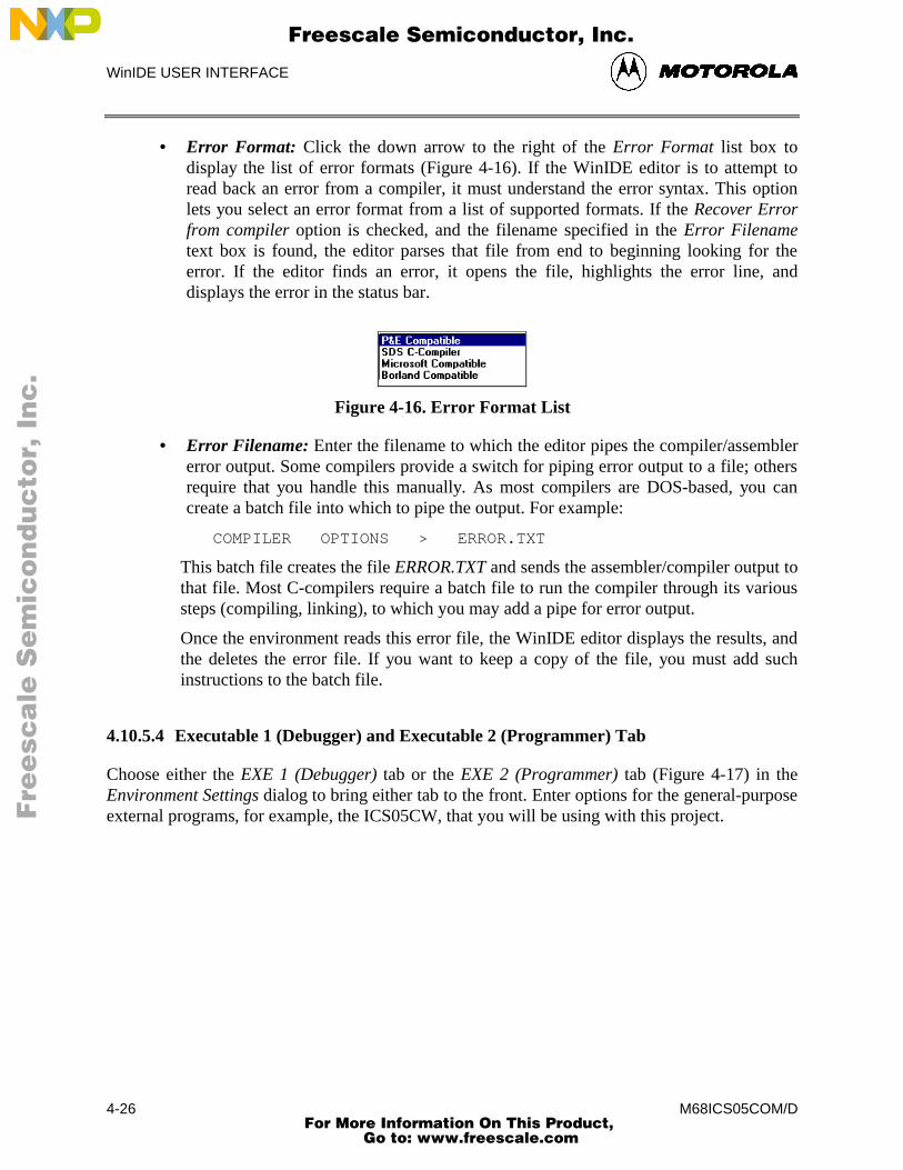
WinIDE USER INTERFACE
M68ICS05COM/D4-26
• Error Format: Click the down arrow to the right of the Error Format list box todisplay the list of error formats (Figure 4-16). If the WinIDE editor is to attempt toread back an error from a compiler, it must understand the error syntax. This optionlets you select an error format from a list of supported formats. If the Recover Errorfrom compiler option is checked, and the filename specified in the Error Filenametext box is found, the editor parses that file from end to beginning looking for theerror. If the editor finds an error, it opens the file, highlights the error line, anddisplays the error in the status bar.
Figure 4-16. Error Format List
• Error Filename: Enter the filename to which the editor pipes the compiler/assemblererror output. Some compilers provide a switch for piping error output to a file; othersrequire that you handle this manually. As most compilers are DOS-based, you cancreate a batch file into which to pipe the output. For example:
COMPILER OPTIONS > ERROR.TXT
This batch file creates the file ERROR.TXT and sends the assembler/compiler output tothat file. Most C-compilers require a batch file to run the compiler through its varioussteps (compiling, linking), to which you may add a pipe for error output.
Once the environment reads this error file, the WinIDE editor displays the results, andthe deletes the error file. If you want to keep a copy of the file, you must add suchinstructions to the batch file.
4.10.5.4 Executable 1 (Debugger) and Executable 2 (Programmer) Tab
Choose either the EXE 1 (Debugger) tab or the EXE 2 (Programmer) tab (Figure 4-17) in theEnvironment Settings dialog to bring either tab to the front. Enter options for the general-purposeexternal programs, for example, the ICS05CW, that you will be using with this project.
Fre
esc
ale
Se
mic
on
du
cto
r, I
Freescale Semiconductor, Inc.
For More Information On This Product, Go to: www.freescale.com
nc
...
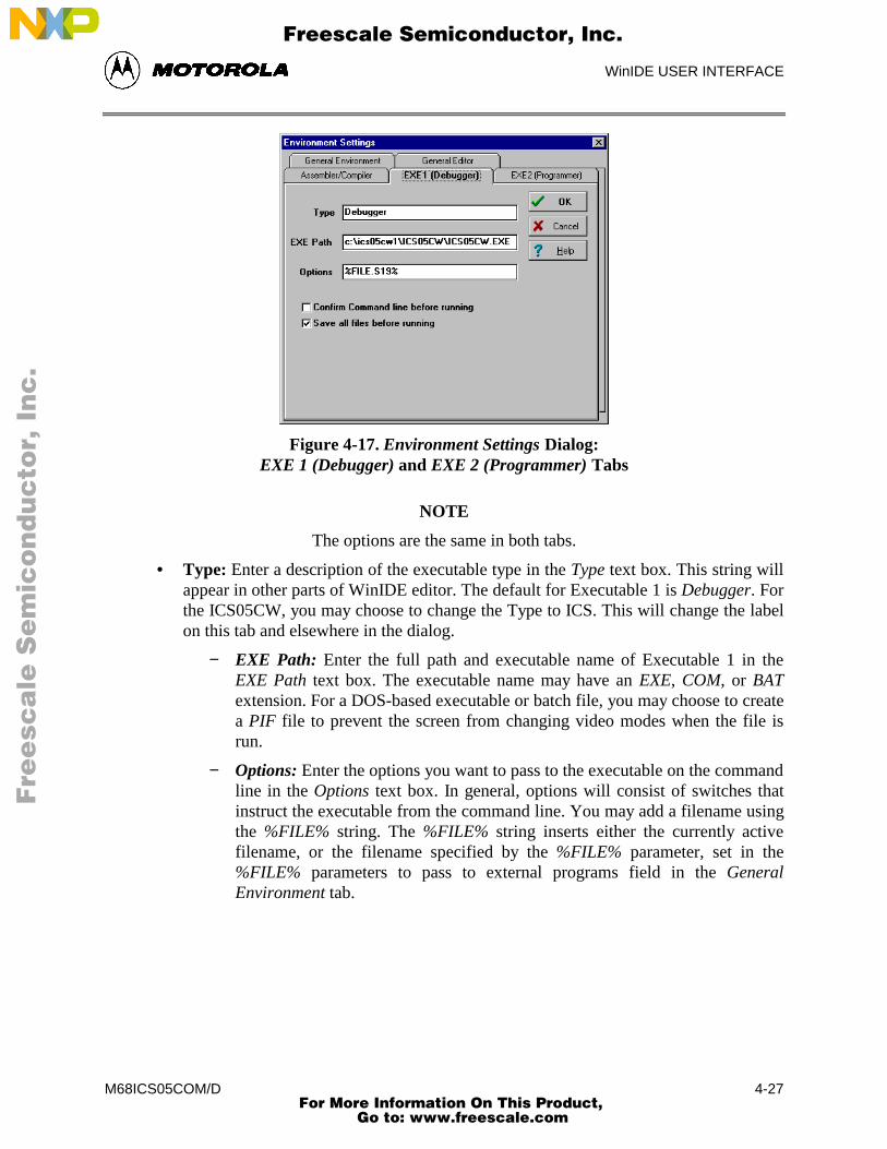
WinIDE USER INTERFACE
M68ICS05COM/D 4-27
Figure 4-17. Environment Settings Dialog:EXE 1 (Debugger) and EXE 2 (Programmer) Tabs
NOTE
The options are the same in both tabs.
• Type: Enter a description of the executable type in the Type text box. This string willappear in other parts of WinIDE editor. The default for Executable 1 is Debugger. Forthe ICS05CW, you may choose to change the Type to ICS. This will change the labelon this tab and elsewhere in the dialog.
− EXE Path: Enter the full path and executable name of Executable 1 in theEXE Path text box. The executable name may have an EXE, COM, or BATextension. For a DOS-based executable or batch file, you may choose to createa PIF file to prevent the screen from changing video modes when the file isrun.
− Options: Enter the options you want to pass to the executable on the commandline in the Options text box. In general, options will consist of switches thatinstruct the executable from the command line. You may add a filename usingthe %FILE% string. The %FILE% string inserts either the currently activefilename, or the filename specified by the %FILE% parameter, set in the%FILE% parameters to pass to external programs field in the GeneralEnvironment tab.
Fre
esc
ale
Se
mic
on
du
cto
r, I
Freescale Semiconductor, Inc.
For More Information On This Product, Go to: www.freescale.com
nc
...
WinIDE USER INTERFACE
M68ICS05COM/D4-28
− Confirm Command line before running: Select this option to display awindow describing the executable to be run and the parameters which will bepassed, just before the assembler/compiler is run. This gives you the option tocancel the assemble/compile, continue as described, or modify parametersbefore continuing. If you do not select this option, the assembler/compiler willbe run without prompting you to confirm parameters.
− Save all files before running: Select this option to save all open files to diskbefore running the executable. This is important since external programs thatmust read the edit file read only the last version saved to disk. In general,always select this option.
− Wait for program completion: Select this option to have the WinIDE editordisable itself until the executable terminates. If you do not select this option,the editor starts the compiler, and allows Windows to manage the program.
4.10.6 Setup Fonts
Select the Setup Fonts option in the Environment menu to open the Setup Fonts dialog (Figure 4-18) to change font options in the editor.
Figure 4-18. Setup Fonts Dialog
• Font: The Font text box displays the name of the current font. To change the currentfont, select another font name from the Font list. Use the scroll arrows if necessary toview all the font choices.
• Font Style: The Font Style text box displays the name of the current font style. Tochange the current font style, select another font style name from the Front Style list.
• Size: The Size text box displays the current font size. To change the size, enter a newnumber in the text box or choose a font size from the list.
Fre
esc
ale
Se
mic
on
du
cto
r, I
Freescale Semiconductor, Inc.
For More Information On This Product, Go to: www.freescale.com
nc
...
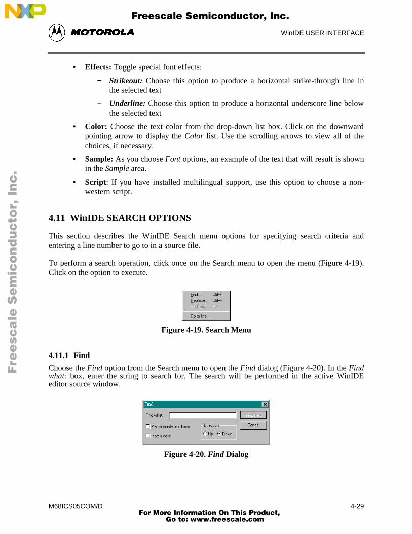
WinIDE USER INTERFACE
M68ICS05COM/D 4-29
• Effects: Toggle special font effects:
− Strikeout: Choose this option to produce a horizontal strike-through line inthe selected text
− Underline: Choose this option to produce a horizontal underscore line belowthe selected text
• Color: Choose the text color from the drop-down list box. Click on the downwardpointing arrow to display the Color list. Use the scrolling arrows to view all of thechoices, if necessary.
• Sample: As you choose Font options, an example of the text that will result is shownin the Sample area.
• Script: If you have installed multilingual support, use this option to choose a non-western script.
4.11 WinIDE SEARCH OPTIONS
This section describes the WinIDE Search menu options for specifying search criteria andentering a line number to go to in a source file.
To perform a search operation, click once on the Search menu to open the menu (Figure 4-19).Click on the option to execute.
Figure 4-19. Search Menu
4.11.1 Find
Choose the Find option from the Search menu to open the Find dialog (Figure 4-20). In the Findwhat: box, enter the string to search for. The search will be performed in the active WinIDEeditor source window.
Figure 4-20. Find Dialog
Fre
esc
ale
Se
mic
on
du
cto
r, I
Freescale Semiconductor, Inc.
For More Information On This Product, Go to: www.freescale.com
nc
...
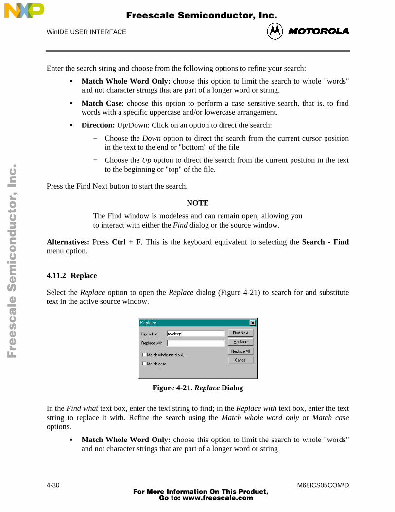
WinIDE USER INTERFACE
M68ICS05COM/D4-30
Enter the search string and choose from the following options to refine your search:
• Match Whole Word Only: choose this option to limit the search to whole "words"and not character strings that are part of a longer word or string.
• Match Case: choose this option to perform a case sensitive search, that is, to findwords with a specific uppercase and/or lowercase arrangement.
• Direction: Up/Down: Click on an option to direct the search:
− Choose the Down option to direct the search from the current cursor positionin the text to the end or "bottom" of the file.
− Choose the Up option to direct the search from the current position in the textto the beginning or "top" of the file.
Press the Find Next button to start the search.
NOTE
The Find window is modeless and can remain open, allowing youto interact with either the Find dialog or the source window.
Alternatives: Press Ctrl + F. This is the keyboard equivalent to selecting the Search - Findmenu option.
4.11.2 Replace
Select the Replace option to open the Replace dialog (Figure 4-21) to search for and substitutetext in the active source window.
Figure 4-21. Replace Dialog
In the Find what text box, enter the text string to find; in the Replace with text box, enter the textstring to replace it with. Refine the search using the Match whole word only or Match caseoptions.
• Match Whole Word Only: choose this option to limit the search to whole "words"and not character strings that are part of a longer word or string
Fre
esc
ale
Se
mic
on
du
cto
r, I
Freescale Semiconductor, Inc.
For More Information On This Product, Go to: www.freescale.com
nc
...
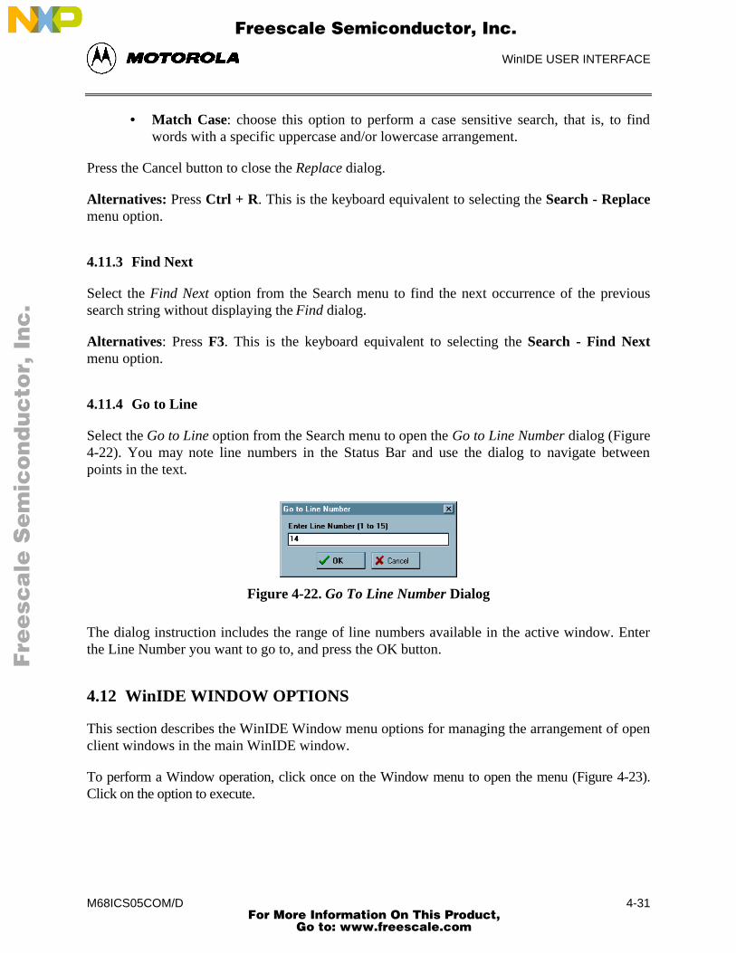
WinIDE USER INTERFACE
M68ICS05COM/D 4-31
• Match Case: choose this option to perform a case sensitive search, that is, to findwords with a specific uppercase and/or lowercase arrangement.
Press the Cancel button to close the Replace dialog.
Alternatives: Press Ctrl + R. This is the keyboard equivalent to selecting the Search - Replacemenu option.
4.11.3 Find Next
Select the Find Next option from the Search menu to find the next occurrence of the previoussearch string without displaying the Find dialog.
Alternatives: Press F3. This is the keyboard equivalent to selecting the Search - Find Nextmenu option.
4.11.4 Go to Line
Select the Go to Line option from the Search menu to open the Go to Line Number dialog (Figure4-22). You may note line numbers in the Status Bar and use the dialog to navigate betweenpoints in the text.
Figure 4-22. Go To Line Number Dialog
The dialog instruction includes the range of line numbers available in the active window. Enterthe Line Number you want to go to, and press the OK button.
4.12 WinIDE WINDOW OPTIONS
This section describes the WinIDE Window menu options for managing the arrangement of openclient windows in the main WinIDE window.
To perform a Window operation, click once on the Window menu to open the menu (Figure 4-23).Click on the option to execute.
Fre
esc
ale
Se
mic
on
du
cto
r, I
Freescale Semiconductor, Inc.
For More Information On This Product, Go to: www.freescale.com
nc
...
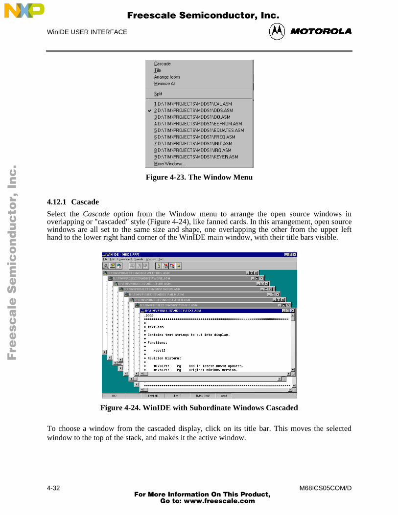
WinIDE USER INTERFACE
M68ICS05COM/D4-32
Figure 4-23. The Window Menu
4.12.1 Cascade
Select the Cascade option from the Window menu to arrange the open source windows inoverlapping or "cascaded" style (Figure 4-24), like fanned cards. In this arrangement, open sourcewindows are all set to the same size and shape, one overlapping the other from the upper lefthand to the lower right hand corner of the WinIDE main window, with their title bars visible.
Figure 4-24. WinIDE with Subordinate Windows Cascaded
To choose a window from the cascaded display, click on its title bar. This moves the selectedwindow to the top of the stack, and makes it the active window.
Fre
esc
ale
Se
mic
on
du
cto
r, I
Freescale Semiconductor, Inc.
For More Information On This Product, Go to: www.freescale.com
nc
...
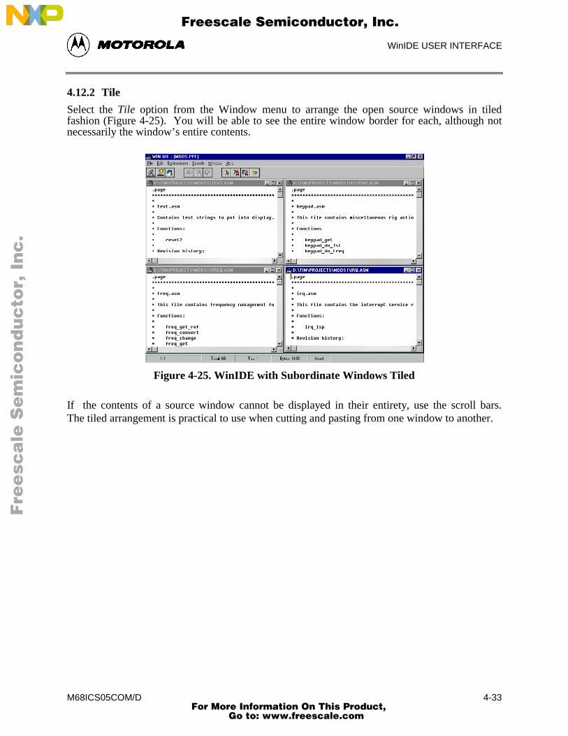
WinIDE USER INTERFACE
M68ICS05COM/D 4-33
4.12.2 Tile
Select the Tile option from the Window menu to arrange the open source windows in tiledfashion (Figure 4-25). You will be able to see the entire window border for each, although notnecessarily the window’s entire contents.
Figure 4-25. WinIDE with Subordinate Windows Tiled
If the contents of a source window cannot be displayed in their entirety, use the scroll bars.The tiled arrangement is practical to use when cutting and pasting from one window to another.
Fre
esc
ale
Se
mic
on
du
cto
r, I
Freescale Semiconductor, Inc.
For More Information On This Product, Go to: www.freescale.com
nc
...
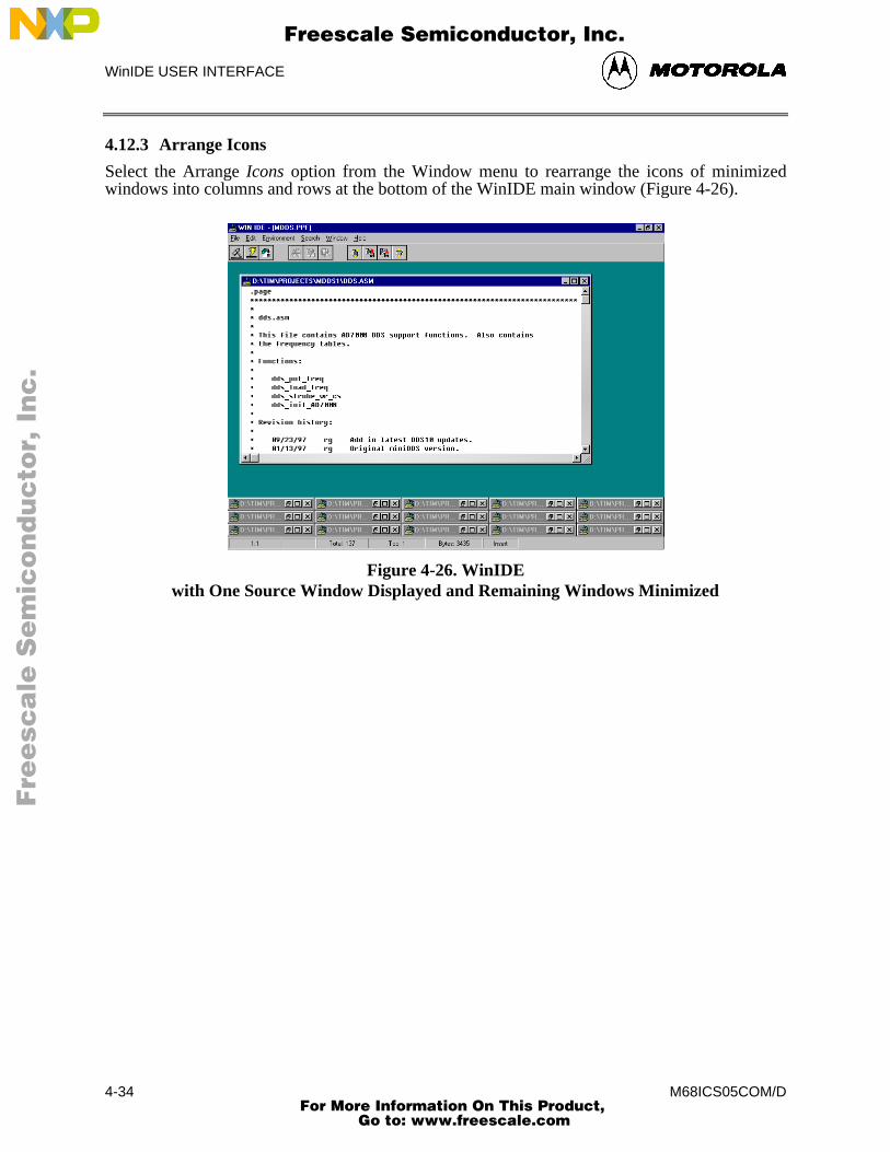
WinIDE USER INTERFACE
M68ICS05COM/D4-34
4.12.3 Arrange Icons
Select the Arrange Icons option from the Window menu to rearrange the icons of minimizedwindows into columns and rows at the bottom of the WinIDE main window (Figure 4-26).
Figure 4-26. WinIDEwith One Source Window Displayed and Remaining Windows Minimized
Fre
esc
ale
Se
mic
on
du
cto
r, I
Freescale Semiconductor, Inc.
For More Information On This Product, Go to: www.freescale.com
nc
...
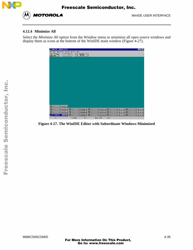
WinIDE USER INTERFACE
M68ICS05COM/D 4-35
4.12.4 Minimize All
Select the Minimize All option from the Window menu to minimize all open source windows anddisplay them as icons at the bottom of the WinIDE main window (Figure 4-27).
Figure 4-27. The WinIDE Editor with Subordinate Windows Minimized
Fre
esc
ale
Se
mic
on
du
cto
r, I
Freescale Semiconductor, Inc.
For More Information On This Product, Go to: www.freescale.com
nc
...
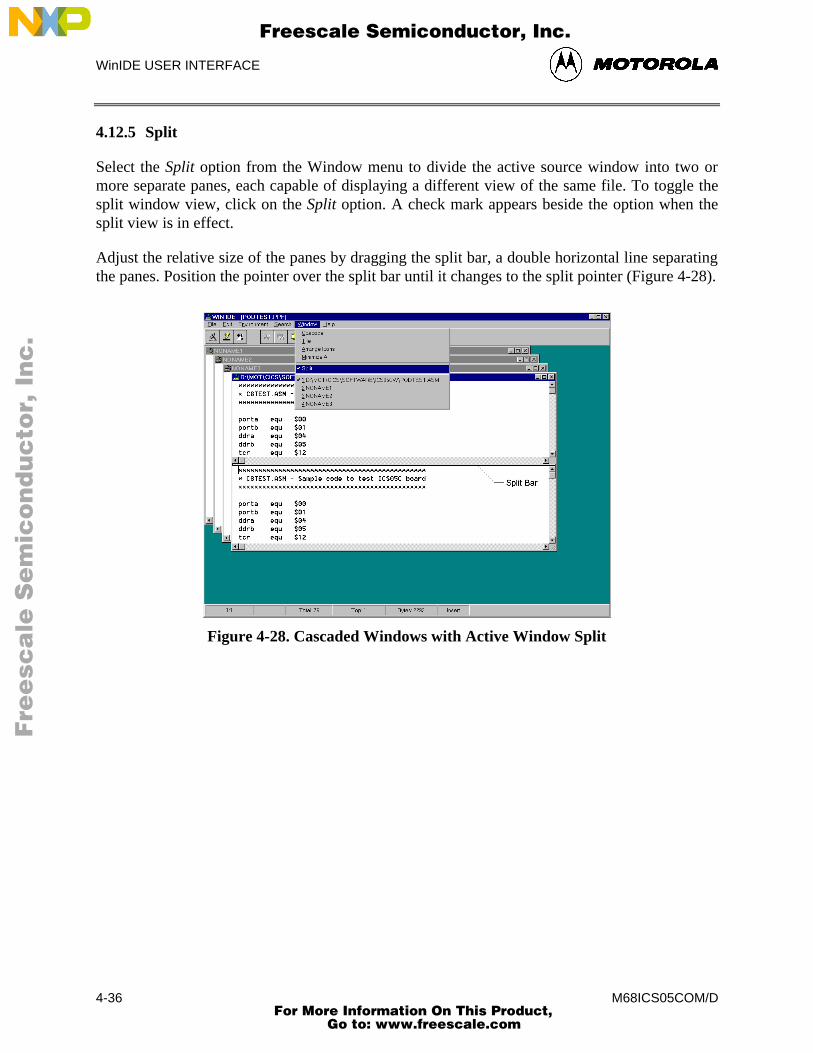
WinIDE USER INTERFACE
M68ICS05COM/D4-36
4.12.5 Split
Select the Split option from the Window menu to divide the active source window into two ormore separate panes, each capable of displaying a different view of the same file. To toggle thesplit window view, click on the Split option. A check mark appears beside the option when thesplit view is in effect.
Adjust the relative size of the panes by dragging the split bar, a double horizontal line separatingthe panes. Position the pointer over the split bar until it changes to the split pointer (Figure 4-28).
Figure 4-28. Cascaded Windows with Active Window Split
Fre
esc
ale
Se
mic
on
du
cto
r, I
Freescale Semiconductor, Inc.
For More Information On This Product, Go to: www.freescale.com
nc
...
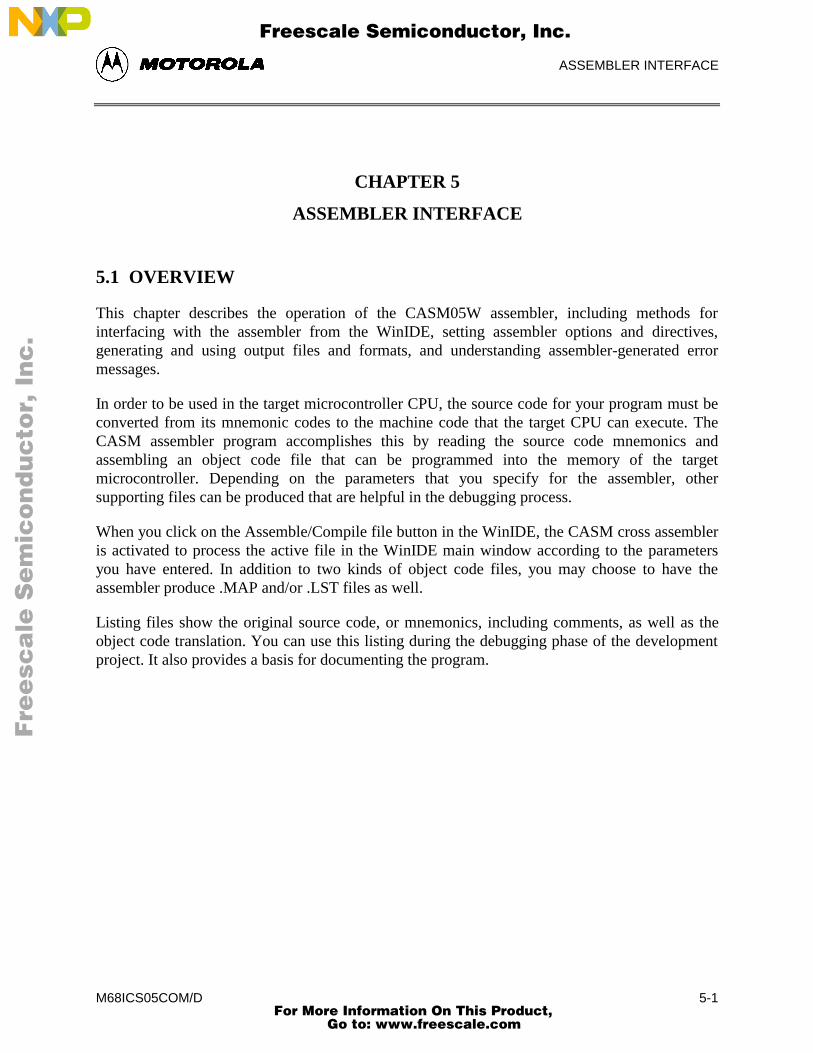
ASSEMBLER INTERFACE
M68ICS05COM/D 5-1
CHAPTER 5
ASSEMBLER INTERFACE
5.1 OVERVIEW
This chapter describes the operation of the CASM05W assembler, including methods forinterfacing with the assembler from the WinIDE, setting assembler options and directives,generating and using output files and formats, and understanding assembler-generated errormessages.
In order to be used in the target microcontroller CPU, the source code for your program must beconverted from its mnemonic codes to the machine code that the target CPU can execute. TheCASM assembler program accomplishes this by reading the source code mnemonics andassembling an object code file that can be programmed into the memory of the targetmicrocontroller. Depending on the parameters that you specify for the assembler, othersupporting files can be produced that are helpful in the debugging process.
When you click on the Assemble/Compile file button in the WinIDE, the CASM cross assembleris activated to process the active file in the WinIDE main window according to the parametersyou have entered. In addition to two kinds of object code files, you may choose to have theassembler produce .MAP and/or .LST files as well.
Listing files show the original source code, or mnemonics, including comments, as well as theobject code translation. You can use this listing during the debugging phase of the developmentproject. It also provides a basis for documenting the program.
Fre
esc
ale
Se
mic
on
du
cto
r, I
Freescale Semiconductor, Inc.
For More Information On This Product, Go to: www.freescale.com
nc
...
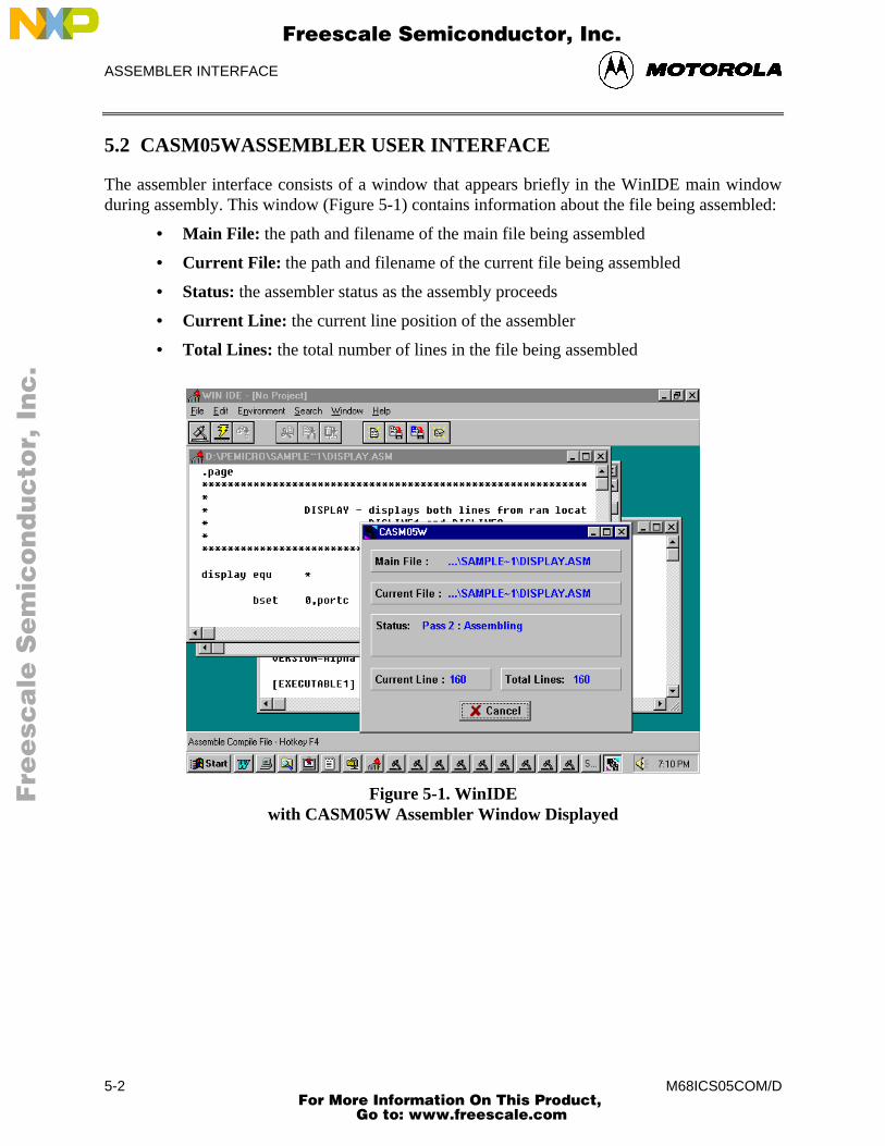
ASSEMBLER INTERFACE
M68ICS05COM/D5-2
5.2 CASM05WASSEMBLER USER INTERFACE
The assembler interface consists of a window that appears briefly in the WinIDE main windowduring assembly. This window (Figure 5-1) contains information about the file being assembled:
• Main File: the path and filename of the main file being assembled
• Current File: the path and filename of the current file being assembled
• Status: the assembler status as the assembly proceeds
• Current Line: the current line position of the assembler
• Total Lines: the total number of lines in the file being assembled
Figure 5-1. WinIDEwith CASM05W Assembler Window Displayed
Fre
esc
ale
Se
mic
on
du
cto
r, I
Freescale Semiconductor, Inc.
For More Information On This Product, Go to: www.freescale.com
nc
...
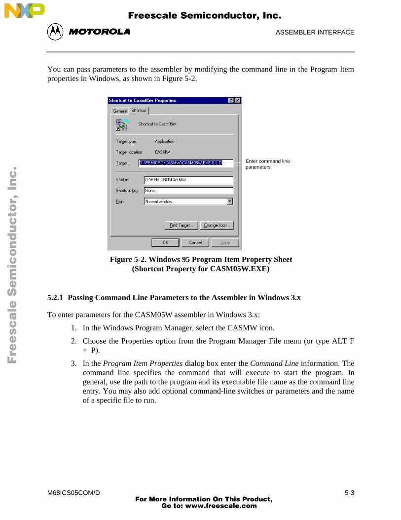
ASSEMBLER INTERFACE
M68ICS05COM/D 5-3
You can pass parameters to the assembler by modifying the command line in the Program Itemproperties in Windows, as shown in Figure 5-2.
Enter command lineparameters
Figure 5-2. Windows 95 Program Item Property Sheet(Shortcut Property for CASM05W.EXE)
5.2.1 Passing Command Line Parameters to the Assembler in Windows 3.x
To enter parameters for the CASM05W assembler in Windows 3.x:
1. In the Windows Program Manager, select the CASMW icon.
2. Choose the Properties option from the Program Manager File menu (or type ALT F+ P).
3. In the Program Item Properties dialog box enter the Command Line information. Thecommand line specifies the command that will execute to start the program. Ingeneral, use the path to the program and its executable file name as the command lineentry. You may also add optional command-line switches or parameters and the nameof a specific file to run.
Fre
esc
ale
Se
mic
on
du
cto
r, I
Freescale Semiconductor, Inc.
For More Information On This Product, Go to: www.freescale.com
nc
...
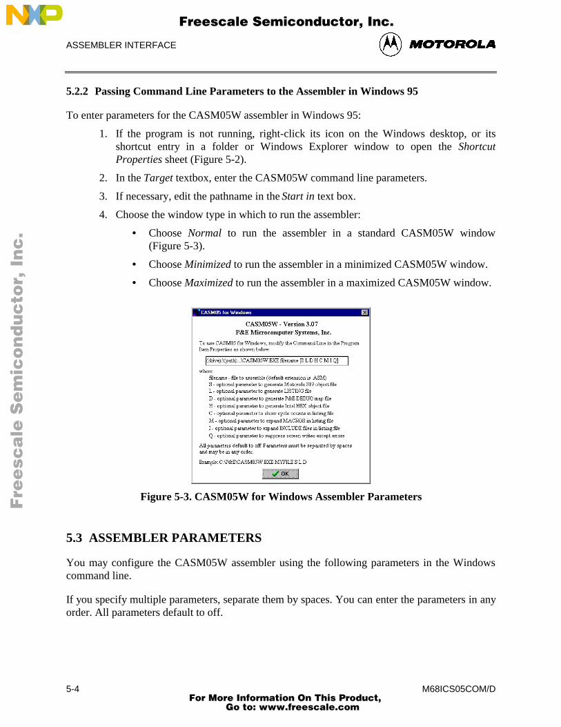
ASSEMBLER INTERFACE
M68ICS05COM/D5-4
5.2.2 Passing Command Line Parameters to the Assembler in Windows 95
To enter parameters for the CASM05W assembler in Windows 95:
1. If the program is not running, right-click its icon on the Windows desktop, or itsshortcut entry in a folder or Windows Explorer window to open the ShortcutProperties sheet (Figure 5-2).
2. In the Target textbox, enter the CASM05W command line parameters.
3. If necessary, edit the pathname in the Start in text box.
4. Choose the window type in which to run the assembler:
• Choose Normal to run the assembler in a standard CASM05W window(Figure 5-3).
• Choose Minimized to run the assembler in a minimized CASM05W window.
• Choose Maximized to run the assembler in a maximized CASM05W window.
Figure 5-3. CASM05W for Windows Assembler Parameters
5.3 ASSEMBLER PARAMETERS
You may configure the CASM05W assembler using the following parameters in the Windowscommand line.
If you specify multiple parameters, separate them by spaces. You can enter the parameters in anyorder. All parameters default to off.
Fre
esc
ale
Se
mic
on
du
cto
r, I
Freescale Semiconductor, Inc.
For More Information On This Product, Go to: www.freescale.com
nc
...
ASSEMBLER INTERFACE
M68ICS05COM/D 5-5
• Filename: Required parameter specifying the pathname and filename of theCASM05W assembler executable
• S: Optional parameter to general Motorola .S19 S-Record object file
• L: Optional parameter to general an .LST listing file
• D: Optional parameter to generate P&E .MAP debugging file
• H: Optional parameter to generate Intel HEX object file
• C: Optional parameter to show cycle counts in listing file
• M: Optional parameter to expand MACROS is listing file
• I: Optional parameter to expand INCLUDE files in listing file
• Q: Optional parameter to suppress screen writes except errors
Example
C:\P&E\CASM05#.EXE MYFILE S L D
5.4 ASSEMBLER OUTPUTS
5.4.1 Object Files
If you specify an object file in the command-line in the Program Item Properties in Windows,using the S or H parameters, the object file is created during assembly. The object file has thesame name as the file being assembled, with the extension .HEX or .S19, depending on thespecification given:
• Motorola uses the S-Record 8-bit object code file format for object files. For moreinformation, see Appendix A: S-Record Information.
• .HEX is the Intel 8-bit object code format.
In either case, the object code file produced by the CASM05W assembler is a text file containingnumbers that represent the binary opcodes and data of the assembled program. This object codefile can be sent to the MCU using a programmer or bootstrap program, at which time it isconverted to the binary format required by the target CPU.
The object filename depends on the choice made in the command line of the Windows ProgramItem Properties. By default, the object filename is that of the file being assembled, with theproper object file format extensions. An existing file with the same name will be overwritten.
Fre
esc
ale
Se
mic
on
du
cto
r, I
Freescale Semiconductor, Inc.
For More Information On This Product, Go to: www.freescale.com
nc
...
ASSEMBLER INTERFACE
M68ICS05COM/D5-6
5.4.2 Map Files
If you specify a map file using the D parameter, the P&E Debug .MAP file is created during theassembly. P&E Microcomputer products (such as the MMDS and the MMEVS) use these mapfiles during the source-level debugging process.
Map files contain the directory path information under which they are created, and cannot,therefore, be moved to a new directory. If you must use the map file from a different directory,place the file in the new directory and reassemble, using the map file option D in the Windowscommand line.
5.4.3 Listing Files
If you specify a listing file using the L parameter in the Windows command line, a file with thesame name as the file being assembled and the extension LST can be produced by the assembler.This file serves as a program listing showing the binary numbers that the CPU needs, alongsidethe assembly language statements from the source code.
For more information about using the assembler listing directives, see the summary of AssemblerDirectives in Table 5-2, beginning in paragraph 5-6.
5.4.4 Files from Other Assemblers
It is possible to use files produced by another assembler with the CASM05W assembler,providing they are properly prepared before using. To prepare a source file from a third-partyassembler for use with the CASM05W, follow these steps:
1. Precede all comments by a semicolon.
2. Using the WinIDE (or other editor) global search and replace command, change anyassembler-specific directives, listing directives, pseudo operations, etc., as required tocreate a file which is compatible with the CASM05W. Remember that assemblerdirectives must begin with the characters $, /, ., or #, and must begin in column 1.
3. If necessary, use the BASE directive to change the default base for the operands(CASM05W defaults to hexadecimal base).
Fre
esc
ale
Se
mic
on
du
cto
r, I
Freescale Semiconductor, Inc.
For More Information On This Product, Go to: www.freescale.com
nc
...
ASSEMBLER INTERFACE
M68ICS05COM/D 5-7
5.5 ASSEMBLER OPTIONS
The CASM05W assembler supports all Motorola opcode mnemonics in the command set. Fordescriptions of the debugging commands, see Chapter 7, ICS05CW Debugging Command Set.
NOTE
Opcodes mnemonics cannot start in column one. If a label beginsthe line, there must be at least one space between the label and theopcode.
5.5.1 Operands and Constants
Operands are addresses, labels, or constants, as defined by the opcode. Assembly-time arithmeticis allowed within operands. Such arithmetic may use these operations:
* multiplication/ division+ addition- subtraction< left shift> right shift% remainder after division& bitwise and| bitwise or^ bitwise xor
Operator precedence follows algebraic rules. You may use parentheses to alter precedence. Ifyour expression contains more than one operator, parenthesis, or embedded space, you must putthe entire expression inside braces ( { } ).
jmp start ;start is a previously defined labeljmp start+3 ;jump to location start + 3jmp (start > 2) ;jump to location start divided by 4
Constants are specific numbers in assembly-language commands. The default base for constantsis hexadecimal, but you may change the default using the Change Base Address dialogs for theMemory and Code windows. To temporarily override the default base, use either the appropriateprefix or suffix (Table 5-1), but not both.
Fre
esc
ale
Se
mic
on
du
cto
r, I
Freescale Semiconductor, Inc.
For More Information On This Product, Go to: www.freescale.com
nc
...
ASSEMBLER INTERFACE
M68ICS05COM/D5-8
The assembler also accepts ASCII constants. Specify an ASCII constant by enclosing it in singleor double quotes. A character ASCII constant has an equivalent value: ‘A’ is the same as 41H.An example of a string constant is:
db “this is a string”
Table 5-1. Change Base Prefixes/Suffixes
Base Prefix Suffix
2 % Q
8 @ O
10 ! T
16 H
5.5.2 Comments
Use semicolons to delineate comments. A comment may start in any column and runs until theend of its line. Additionally, if any line has an asterisk (*) or semicolon (;) in column 1, the entireline is a comment.
5.6 ASSEMBLER DIRECTIVES
Assembler directives are keywords that control the progress and the modes of the CASM05Wassembler. To invoke an assembler directive, enter a /, #, or $ as the first character of a line.Enter the directive immediately after this initial character, along with the appropriate parametersvalues.
Directives supported by the assembler vary according to manufacturer. Table 5-2 summarizes theCASM05W assembler directives. A caret (^) indicates that a parameter value must follow thedirective. Note also that a space must separate a directive and its parameter value.
5.6.1 BASE
The BASE assembler directive changes the default base of the current file. The parameterspecified must be in the current base or have a base qualifier (prefix or suffix). The next baseremains in effect until the end of the file, or until you enter another BASE directive.
The original default base is hexadecimal, but you can change the default to binary, octal, ordecimal default bases instead. It is good practice to specify a base explicitly so that you arealways sure that base is currently in effect.
Fre
esc
ale
Se
mic
on
du
cto
r, I
Freescale Semiconductor, Inc.
For More Information On This Product, Go to: www.freescale.com
nc
...
ASSEMBLER INTERFACE
M68ICS05COM/D 5-9
5.6.2 Cycle Adder
The CASM05W assembler contains an internal counter for instruction cycles called the cycleadder. Two assembler directives, CYCLE_ADDER_ON and CYCLE_ADDER_OFF, controlthis counter.
When the assembler encounters the CYCLE_ADDER_ON directive, it clears the cycle adder.The cycle adder starts a running total of instruction cycles as subsequent instructions areassembled. For instructions that have variables numbers of instruction cycles, the cycle adderuses the smallest number.
When the assembler encounters the CYCLE_ADDER_OFF directive, it writes the current cycle-adder value to the .LST file and disables the cycle adder.
Fre
esc
ale
Se
mic
on
du
cto
r, I
Freescale Semiconductor, Inc.
For More Information On This Product, Go to: www.freescale.com
nc
...
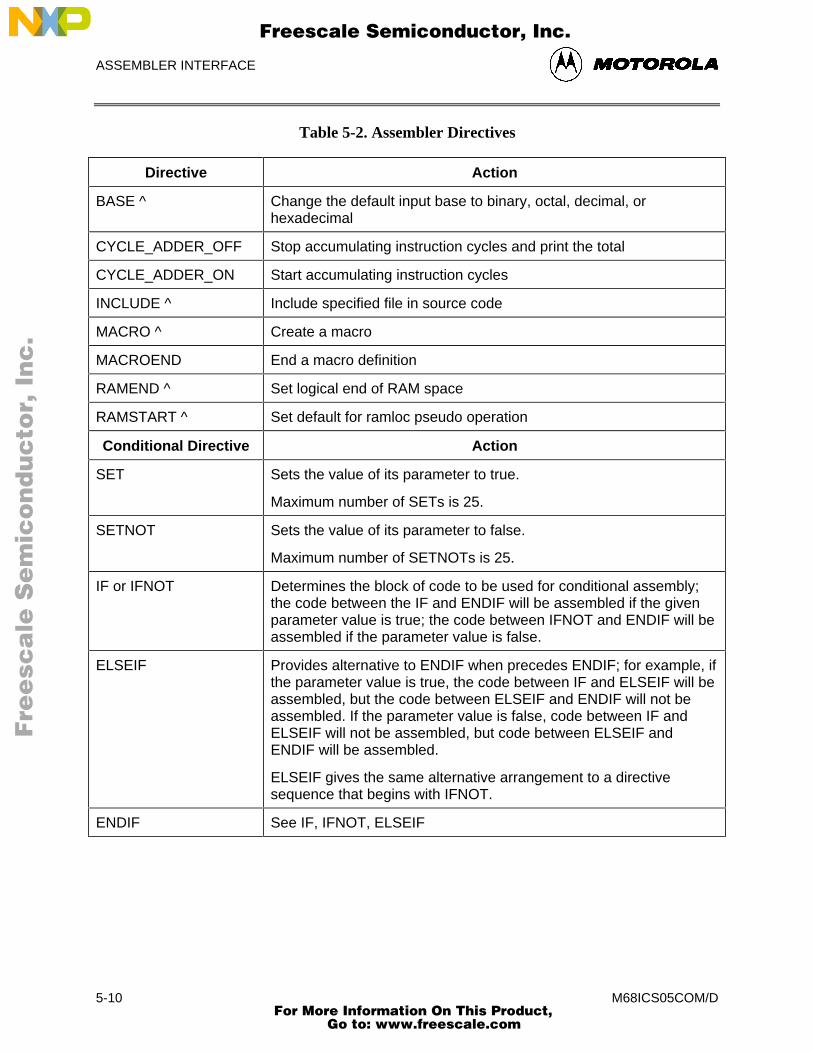
ASSEMBLER INTERFACE
M68ICS05COM/D5-10
Table 5-2. Assembler Directives
Directive Action
BASE ^ Change the default input base to binary, octal, decimal, orhexadecimal
CYCLE_ADDER_OFF Stop accumulating instruction cycles and print the total
CYCLE_ADDER_ON Start accumulating instruction cycles
INCLUDE ^ Include specified file in source code
MACRO ^ Create a macro
MACROEND End a macro definition
RAMEND ^ Set logical end of RAM space
RAMSTART ^ Set default for ramloc pseudo operation
Conditional Directive Action
SET Sets the value of its parameter to true.
Maximum number of SETs is 25.
SETNOT Sets the value of its parameter to false.
Maximum number of SETNOTs is 25.
IF or IFNOT Determines the block of code to be used for conditional assembly;the code between the IF and ENDIF will be assembled if the givenparameter value is true; the code between IFNOT and ENDIF will beassembled if the parameter value is false.
ELSEIF Provides alternative to ENDIF when precedes ENDIF; for example, ifthe parameter value is true, the code between IF and ELSEIF will beassembled, but the code between ELSEIF and ENDIF will not beassembled. If the parameter value is false, code between IF andELSEIF will not be assembled, but code between ELSEIF andENDIF will be assembled.
ELSEIF gives the same alternative arrangement to a directivesequence that begins with IFNOT.
ENDIF See IF, IFNOT, ELSEIF
Fre
esc
ale
Se
mic
on
du
cto
r, I
Freescale Semiconductor, Inc.
For More Information On This Product, Go to: www.freescale.com
nc
...
ASSEMBLER INTERFACE
M68ICS05COM/D 5-11
5.6.3 Conditional Assembly
The CASM05W assembler allows you to specify blocks of code to be assembled only uponcertain conditions. To set up such conditional assembly procedures, use the conditionalassembler directives summarized in Table 5.2.
Example of Conditional Assembly Directives
$SET debug ;sets debug = true$SETNOT test ;sets test = falsenop ;always assemblesnop ;always assembles$IF debug ;if debug = truejmp start ;assembles$ELSEIF ;if debug = falsejmp end ;does not assemble$ENDIF ;nop ;always assemblesnop ;always assembles$IF test ;if test = truejmp test ;does not assemble$ENDIF ;
5.6.4 INCLUDE
If the CASM05W assembler encounters the INCLUDE directive, it takes source code from thespecified file and continues until it encounters another INCLUDE directive or until it reaches theend of the main file. When the assembler reaches the end of the main file, it continues takingsource code from the file that contained the include directive.
The file specification of the INCLUDE directive must be in either single or double quotes. If thefile is not in the current directory, the specification should also include the full path name as wellas the filename.
You may nest included to a maximum depth of 10, that is, each included file may contain up to 10additional included files.
Examples
$INCLUDE “INIT.ASM”
$INCLUDE “C:\project\init.asm*"
Fre
esc
ale
Se
mic
on
du
cto
r, I
Freescale Semiconductor, Inc.
For More Information On This Product, Go to: www.freescale.com
nc
...
ASSEMBLER INTERFACE
M68ICS05COM/D5-12
5.6.5 MACRO
A macro is a named block of text to be assembled. Similar in some ways to an included file, themacro allows labels and parameter values.
The MACRO directive begins the macro definition. The name of the macro is the parametervalue for the MACRO direction. All subsequent code, until the assembler encounters theMACROEND directive, is considered the macro definition.
No assembler directives may be used within a macro, no does the definition require parameternames. Instead, the macro definition includes the sequential indicators %n for the nth parametervalues of the macro call. The assembler will ignore parameter values on the MACRO directiveline, so such values may be helpful for internal documentation.
Example
This macro example illustrates a macro that divides the accumulator value by 4:
$MACRO divide_by_4 ;starts macro definitionasr a ;divides accumulator by 2asr a ;divides quotient by 2$MACROEND ;ends macro definition
This macro example illustrates a macro that creates a time delay:
$MACRO delay countldaa #$01
loop: decabne loop
$MACROEND
In this macro, the CASM05W assembler ignores the parameter count on the MACRO directiveline. The parameter count merely indicates the role of the parameter value passed to the macro.That value is substituted for the sequential indicator %1. The first time this macro is called, theCASM05W assembler changes the label loop, on lines 3 and 4, to loop:0001. If the calling line
delay 100t
invokes this macro, the loop would occur 100 times. The suffix t represents the decimal base.
The CASM05W assembler ignores extra parameter values sent to a macro. If the macro does notreceive enough parameter values, the assembler issues an error message.
Labels change automatically each time they are used. Labels used within macros may not belonger than 10 characters, because the assembler appends a four-digit hexadecimal number to thelabel to insure label uniqueness.
Although code may not jump into a macro, it may jump out of a macro. Macros cannot beforward-referenced.
Fre
esc
ale
Se
mic
on
du
cto
r, I
Freescale Semiconductor, Inc.
For More Information On This Product, Go to: www.freescale.com
nc
...
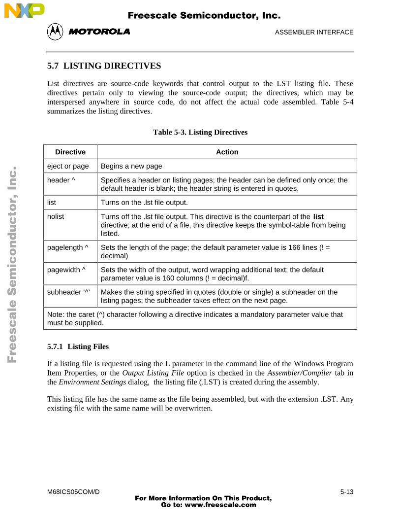
ASSEMBLER INTERFACE
M68ICS05COM/D 5-13
5.7 LISTING DIRECTIVES
List directives are source-code keywords that control output to the LST listing file. Thesedirectives pertain only to viewing the source-code output; the directives, which may beinterspersed anywhere in source code, do not affect the actual code assembled. Table 5-4summarizes the listing directives.
Table 5-3. Listing Directives
Directive Action
eject or page Begins a new page
header ^ Specifies a header on listing pages; the header can be defined only once; thedefault header is blank; the header string is entered in quotes.
list Turns on the .lst file output.
nolist Turns off the .lst file output. This directive is the counterpart of the listdirective; at the end of a file, this directive keeps the symbol-table from beinglisted.
pagelength ^ Sets the length of the page; the default parameter value is 166 lines (! =decimal)
pagewidth ^ Sets the width of the output, word wrapping additional text; the defaultparameter value is 160 columns (! = decimal)f.
subheader ‘^’ Makes the string specified in quotes (double or single) a subheader on thelisting pages; the subheader takes effect on the next page.
Note: the caret (^) character following a directive indicates a mandatory parameter value thatmust be supplied.
5.7.1 Listing Files
If a listing file is requested using the L parameter in the command line of the Windows ProgramItem Properties, or the Output Listing File option is checked in the Assembler/Compiler tab inthe Environment Settings dialog, the listing file (.LST) is created during the assembly.
This listing file has the same name as the file being assembled, but with the extension .LST. Anyexisting file with the same name will be overwritten.
Fre
esc
ale
Se
mic
on
du
cto
r, I
Freescale Semiconductor, Inc.
For More Information On This Product, Go to: www.freescale.com
nc
...
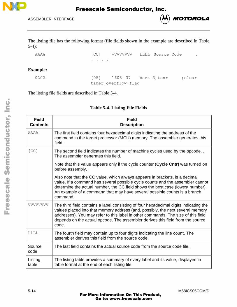
ASSEMBLER INTERFACE
M68ICS05COM/D5-14
The listing file has the following format (file fields shown in the example are described in Table5-4):
AAAA [CC] VVVVVVVV LLLL Source Code .. . . .
Example:
0202 [05] 1608 37 bset 3,tcsr ;cleartimer overflow flag
The listing file fields are described in Table 5-4.
Table 5-4. Listing File Fields
FieldContents
FieldDescription
AAAA The first field contains four hexadecimal digits indicating the address of thecommand in the target processor (MCU) memory. The assembler generates thisfield.
[CC] The second field indicates the number of machine cycles used by the opcode. .The assembler generates this field.
Note that this value appears only if the cycle counter (Cycle Cntr) was turned onbefore assembly.
Also note that the CC value, which always appears in brackets, is a decimalvalue. If a command has several possible cycle counts and the assembler cannotdetermine the actual number, the CC field shows the best case (lowest number).An example of a command that may have several possible counts is a branchcommand.
VVVVVVVV The third field contains a label consisting of four hexadecimal digits indicating thevalues placed into that memory address (and, possibly, the next several memoryaddresses). You may refer to this label in other commands. The size of this fielddepends on the actual opcode. The assembler derives this field from the sourcecode.
LLLL The fourth field may contain up to four digits indicating the line count. Theassembler derives this field from the source code.
Sourcecode
The last field contains the actual source code from the source code file.
Listingtable
The listing table provides a summary of every label and its value, displayed intable format at the end of each listing file.
Fre
esc
ale
Se
mic
on
du
cto
r, I
Freescale Semiconductor, Inc.
For More Information On This Product, Go to: www.freescale.com
nc
...
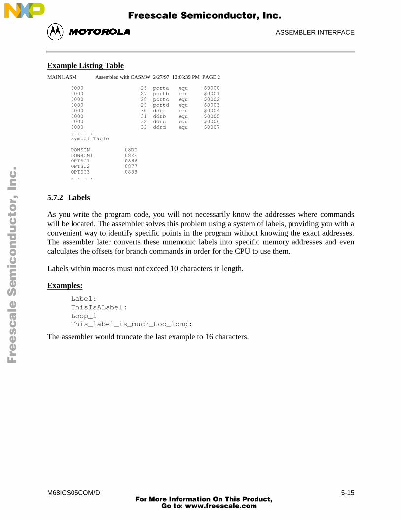
ASSEMBLER INTERFACE
M68ICS05COM/D 5-15
Example Listing TableMAIN1.ASM Assembled with CASMW 2/27/97 12:06:39 PM PAGE 2
0000 26 porta equ $00000000 27 portb equ $00010000 28 portc equ $00020000 29 portd equ $00030000 30 ddra equ $00040000 31 ddrb equ $00050000 32 ddrc equ $00060000 33 ddrd equ $0007. . . .Symbol Table
DONSCN 08DDDONSCN1 08EEOPTSC1 0866OPTSC2 0877OPTSC3 0888. . . .
5.7.2 Labels
As you write the program code, you will not necessarily know the addresses where commandswill be located. The assembler solves this problem using a system of labels, providing you with aconvenient way to identify specific points in the program without knowing the exact addresses.The assembler later converts these mnemonic labels into specific memory addresses and evencalculates the offsets for branch commands in order for the CPU to use them.
Labels within macros must not exceed 10 characters in length.
Examples:
Label:ThisIsALabel:Loop_1This_label_is_much_too_long:
The assembler would truncate the last example to 16 characters.
Fre
esc
ale
Se
mic
on
du
cto
r, I
Freescale Semiconductor, Inc.
For More Information On This Product, Go to: www.freescale.com
nc
...
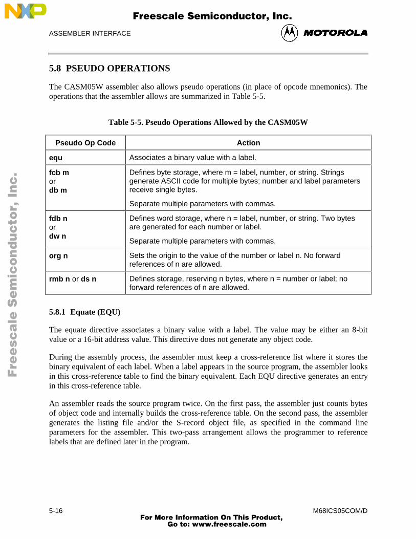
ASSEMBLER INTERFACE
M68ICS05COM/D5-16
5.8 PSEUDO OPERATIONS
The CASM05W assembler also allows pseudo operations (in place of opcode mnemonics). Theoperations that the assembler allows are summarized in Table 5-5.
Table 5-5. Pseudo Operations Allowed by the CASM05W
Pseudo Op Code Action
equ Associates a binary value with a label.
fcb mordb m
Defines byte storage, where m = label, number, or string. Stringsgenerate ASCII code for multiple bytes; number and label parametersreceive single bytes.
Separate multiple parameters with commas.
fdb nordw n
Defines word storage, where n = label, number, or string. Two bytesare generated for each number or label.
Separate multiple parameters with commas.
org n Sets the origin to the value of the number or label n. No forwardreferences of n are allowed.
rmb n or ds n Defines storage, reserving n bytes, where n = number or label; noforward references of n are allowed.
5.8.1 Equate (EQU)
The equate directive associates a binary value with a label. The value may be either an 8-bitvalue or a 16-bit address value. This directive does not generate any object code.
During the assembly process, the assembler must keep a cross-reference list where it stores thebinary equivalent of each label. When a label appears in the source program, the assembler looksin this cross-reference table to find the binary equivalent. Each EQU directive generates an entryin this cross-reference table.
An assembler reads the source program twice. On the first pass, the assembler just counts bytesof object code and internally builds the cross-reference table. On the second pass, the assemblergenerates the listing file and/or the S-record object file, as specified in the command lineparameters for the assembler. This two-pass arrangement allows the programmer to referencelabels that are defined later in the program.
Fre
esc
ale
Se
mic
on
du
cto
r, I
Freescale Semiconductor, Inc.
For More Information On This Product, Go to: www.freescale.com
nc
...
ASSEMBLER INTERFACE
M68ICS05COM/D 5-17
EQU directives should appear near the beginning of a program, before their labels are used byother program statements. If the assembler encounters a label before it has been defined, theassembler has no choice but to assume the worse case, and assign the label a 16-bit addressvalue. This would cause the extended addressing mode to be used in places where the moreefficient direct addressing mode could have been used. In other cases, the indexed 16-bit offsetaddressing mode may be used where a more efficient 8-bit or no offset indexed command couldhave been used.
5.8.2 Form Constant Byte (FCB)
The arguments for this assembler directive are labels or numbers (separated by commas) that theassembler can convert into a single byte of data. Each byte specified by the FCB directivegenerates a byte of machine code in the object code file. Use FCB directives to define constantsin a program.
5.8.3 Form Double Byte (FDB)
The arguments for this assembler directive are labels or numbers (separated by commas) that theassembler can convert into 16-bit data values. Each argument specified in an FDB directivegenerates two bytes of machine code in the object code file.
5.8.4 Originate (ORG)
The originate directive sets the location counter for the assembler. The location counter keepstrack of the address where the next byte of machine code will be stored in memory.
As the assembler translates program statements into machine code commands and data, itadvances the location counter to point to the next available memory location.
Every program has at least one ORG directive, to establish the program’s starting place. Mostcomplete programs will also have a second ORG directive near the end of the program to set thelocation counter to the address where the reset and interrupt vectors are located. You must alwaysspecify the reset vector. It is good practice to also specify interrupt vectors, even if you do notexpect to use interrupts.
5.8.5 Reserve Memory Byte (RMB)
Use this assembler directive to set aside space in RAM for program variables. The RMBdirective does not generate any object code, but it normally generates an entry in the assembler’sinternal cross-reference table.
Fre
esc
ale
Se
mic
on
du
cto
r, I
Freescale Semiconductor, Inc.
For More Information On This Product, Go to: www.freescale.com
nc
...
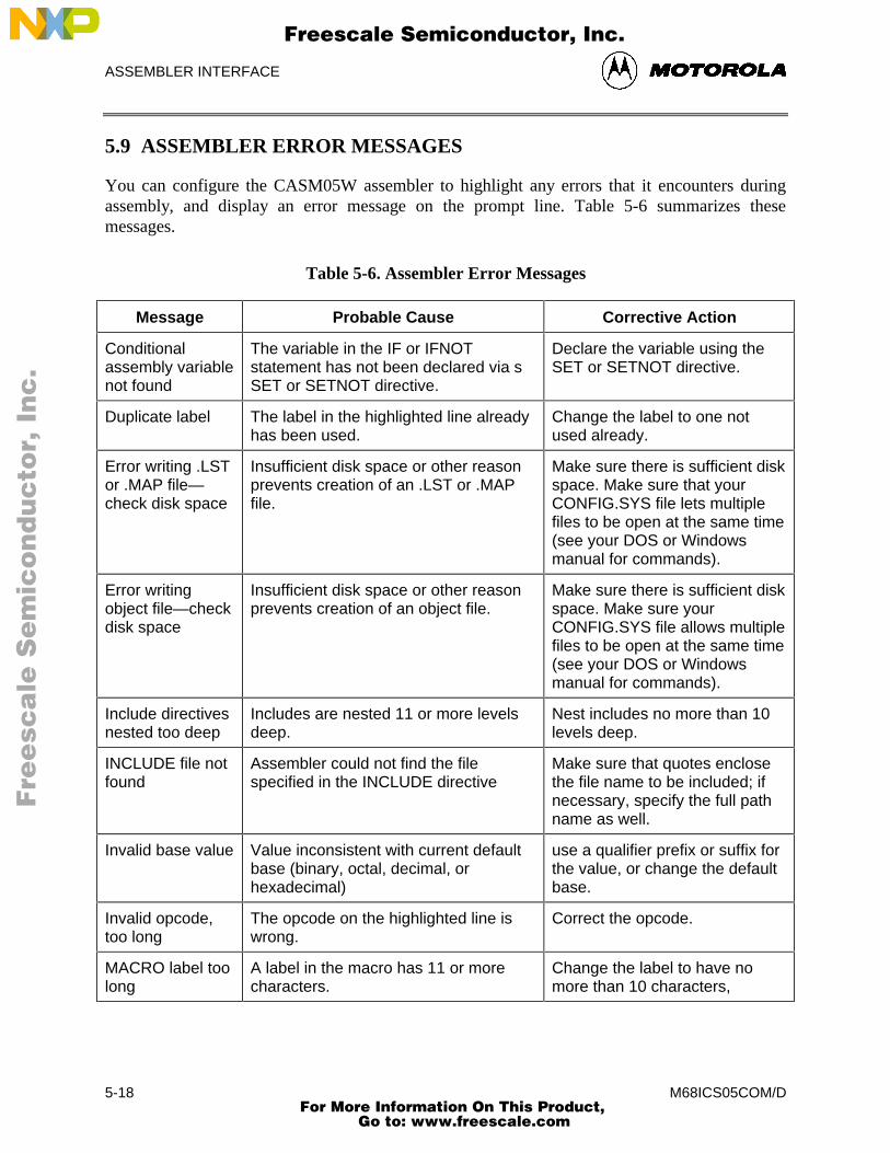
ASSEMBLER INTERFACE
M68ICS05COM/D5-18
5.9 ASSEMBLER ERROR MESSAGES
You can configure the CASM05W assembler to highlight any errors that it encounters duringassembly, and display an error message on the prompt line. Table 5-6 summarizes thesemessages.
Table 5-6. Assembler Error Messages
Message Probable Cause Corrective Action
Conditionalassembly variablenot found
The variable in the IF or IFNOTstatement has not been declared via sSET or SETNOT directive.
Declare the variable using theSET or SETNOT directive.
Duplicate label The label in the highlighted line alreadyhas been used.
Change the label to one notused already.
Error writing .LSTor .MAP file—check disk space
Insufficient disk space or other reasonprevents creation of an .LST or .MAPfile.
Make sure there is sufficient diskspace. Make sure that yourCONFIG.SYS file lets multiplefiles to be open at the same time(see your DOS or Windowsmanual for commands).
Error writingobject file—checkdisk space
Insufficient disk space or other reasonprevents creation of an object file.
Make sure there is sufficient diskspace. Make sure yourCONFIG.SYS file allows multiplefiles to be open at the same time(see your DOS or Windowsmanual for commands).
Include directivesnested too deep
Includes are nested 11 or more levelsdeep.
Nest includes no more than 10levels deep.
INCLUDE file notfound
Assembler could not find the filespecified in the INCLUDE directive
Make sure that quotes enclosethe file name to be included; ifnecessary, specify the full pathname as well.
Invalid base value Value inconsistent with current defaultbase (binary, octal, decimal, orhexadecimal)
use a qualifier prefix or suffix forthe value, or change the defaultbase.
Invalid opcode,too long
The opcode on the highlighted line iswrong.
Correct the opcode.
MACRO label toolong
A label in the macro has 11 or morecharacters.
Change the label to have nomore than 10 characters,
Fre
esc
ale
Se
mic
on
du
cto
r, I
Freescale Semiconductor, Inc.
For More Information On This Product, Go to: www.freescale.com
nc
...
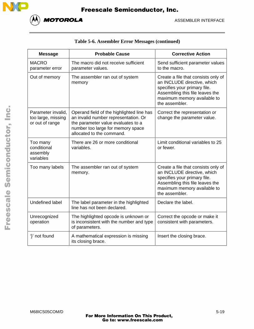
ASSEMBLER INTERFACE
M68ICS05COM/D 5-19
Table 5-6. Assembler Error Messages (continued)
Message Probable Cause Corrective Action
MACROparameter error
The macro did not receive sufficientparameter values.
Send sufficient parameter valuesto the macro.
Out of memory The assembler ran out of systemmemory
Create a file that consists only ofan INCLUDE directive, whichspecifies your primary file.Assembling this file leaves themaximum memory available tothe assembler.
Parameter invalid,too large, missingor out of range
Operand field of the highlighted line hasan invalid number representation. Orthe parameter value evaluates to anumber too large for memory spaceallocated to the command.
Correct the representation orchange the parameter value.
Too manyconditionalassemblyvariables
There are 26 or more conditionalvariables.
Limit conditional variables to 25or fewer.
Too many labels The assembler ran out of systemmemory.
Create a file that consists only ofan INCLUDE directive, whichspecifies your primary file.Assembling this file leaves themaximum memory available tothe assembler.
Undefined label The label parameter in the highlightedline has not been declared.
Declare the label.
Unrecognizedoperation
The highlighted opcode is unknown oris inconsistent with the number and typeof parameters.
Correct the opcode or make itconsistent with parameters.
‘}’ not found A mathematical expression is missingits closing brace.
Insert the closing brace.
Fre
esc
ale
Se
mic
on
du
cto
r, I
Freescale Semiconductor, Inc.
For More Information On This Product, Go to: www.freescale.com
nc
...
ASSEMBLER INTERFACE
M68ICS05COM/D5-20
5.10 USING FILES FROM OTHER ASSEMBLERS
To prepare a source file made by another assembler with the CASM05W, follow these steps:
1. Divide large files into smaller files no larger than 75K. Typically, use one file forsystem variables and EQUates, another file for I/O routines. The main file should bethe one called. Remember that include filenames must be in quotes and must containthe file extensions.
2. Make sure all comments in the source file are preceded by a semicolon.
3. Use the global find-and-replace operation in the editor to change any assemblerdirectives, listing directives, and/or pseudo operations, if they exist in the source code.Remember that assembler directives must begin with the character $, /,., or #, andmust start in column 1.
4. If necessary, use the BASE directive to change the default base for operands(CASM05W defaults to hexadecimal).
Fre
esc
ale
Se
mic
on
du
cto
r, I
Freescale Semiconductor, Inc.
For More Information On This Product, Go to: www.freescale.com
nc
...
SIMULATOR USER INTERFACE
M68ICS05COM/D 6-1
CHAPTER 6
ICS05CW SIMULATOR USER INTERFACE
6.1 OVERVIEW
This chapter describes the in-circuit simulator user interface, toolbar buttons, windows, sub-windows, messages, and menu options.
6.2 THE ICS05CW IN-CIRCUIT SIMULATOR
The ICS05CW.EXE is an in-circuit simulator for Motorola 68HC05c series microcontrollers thatruns in Windows 3.x and Windows 95. The ICS05CW can get inputs and outputs (I/O) for thetarget device from an external pod, the M68ICS05C board, that is attached to the host computer.If you want to use actual inputs and outputs (I/O) from your own target board, you may attach theM68ICS05C board to your target board using the supplied extension cable.
The ICS05CW in-circuit simulator software is the debugging component of a completedevelopment environment when used in conjunction with the WinIDE editing environment andthe CASM05W command-line assembler.
6.2.1 ICS05CW Simulation Speed
The ICS05CW is not a real-time debugger. The speed at which the simulator executes code ismuch slower than the speed at which the actual processor can execute code. Therefore, if thereare any critical timing issues to be resolved, you should use an emulator for the HC05C devicesinstead of the ICS05CW.
Alternately, you may simulate using the slow mode, then program an EPROM device to checkthe full speed operation.
NOTE
An actual speed of 10KHz indicates that the simulator on your hostPC is running at the same speed as the real MCU with a 20-KHzcrystal (a divide-by-2 is attached to the internal oscillator output).Typical values for actual speed are 3 to 50 kHz.
Fre
esc
ale
Se
mic
on
du
cto
r, I
Freescale Semiconductor, Inc.
For More Information On This Product, Go to: www.freescale.com
nc
...
SIMULATOR USER INTERFACE
M68ICS05COM/D6-2
To calculate actual speed of the assembled code on the target MCU, you need a stopwatch andsome source code. Follow these steps:
1. Load your code using the LOAD command on the ICS05CW Status Windowcommand line.
2. Set the program counter to the beginning of the routine for which you wish tomeasure the speed.
3. Clear the cycle counter using the CYCLE (or CY) command with the 0 parameter,then press Enter:
4. Ready your stopwatch.
5. Enter the GO or G command on the ICS05CW Status Window command line.
6. Start the stopwatch and press the ENTER button simultaneously to begin codeexecution.
7. After 10 seconds, simultaneously stop the watch and execution (the fastest way tostop execution is to press the spacebar). Execution halts.
8. Now enter the CYCLES or CY command on the Status Window command line; thedecimal value cycle count is displayed.
9. Divide the cycle count by 10. The result is the actual speed in kHz.
6.2.2 System Requirements for Running the ICS05CW
The ICS05CW runs under Windows 3.1 or Windows 95. There is a separate 32-bit version of theICS05CW software for Windows 95/NT available directly from P&E Microcomputer Systems.
Your host computer should have a minimum of 2 MB of RAM (system memory) available forassembly processes, as well as sufficient disk space to store the files that the ICS05CW creates.
6.2.3 File Types and Formats
You can use a number of file types in conjunction with the ICS05CW simulator. The followingtopics describe the use and structure of each type.
• Project Files: Project files store two types of information:
− Desktop information includes all the information stored concerning the filesthat are currently open in the project. Whenever you save the project file,WinIDE records information about each window open in the desktop,including:
♦ Window size
♦ Window position
Fre
esc
ale
Se
mic
on
du
cto
r, I
Freescale Semiconductor, Inc.
For More Information On This Product, Go to: www.freescale.com
nc
...
SIMULATOR USER INTERFACE
M68ICS05COM/D 6-3
♦ Window style (Maximized/Minimized/Normal)
♦ Markers currently set
− Environment Settings
♦ User settings
♦ WinIDE configuration parameters as specified in the EnvironmentSettings dialog tabs
When you open the project, or if the project is open when the WinIDE starts, files areall opened with the settings stored in the project file.
• S19 (Object) Files: The ICS05CW software accepts any standard Motorola S19 filesas input for simulation. S19 object files can be created by any HC05 assembler (suchas CASM05W), and contain the actual object code that is simulated by the ICS05CW.Specify the S19 files to use on the command line or load it using the LOAD commandin the ICS05CW Status window.
− The object file has the same name as the file assembled, with the extension.HEX or .S19, and contains the actual assembled (or object) code to debug. Ifyou specify an object file in the environment settings, it is created duringassembly.
− The CASMW (and some other assemblers) product object files in the .S19format. The Motorola S19 object code format is described in detail inAppendix A. HEX files are the Intel 8-bit object code format.
• Map Files contain source level debugging information. To debug symbolic or sourcecode in the code window you must also load one or more P&E map-files. The *.MAPsource-level map file can be generated by specifying the map files option on thecommand line when running the CASMW assembler, or loaded using the LOADMAPcommand in the ICS05CW Status window. If you specify a map file in theenvironment settings, it is created during assembly.
NOTE
Map files contain directory information, so cannot be moved. Toplace map files in another directory, move the map file to the newdirectory and reassemble the file in the new directory so the newmap file will contain the correct directory information.
If you use a third party assembly language or C compiler, it mustbe able to produce compatible source-level map files.
• Error Files contain assembly error information. The CASMW highlights any errorsthat it encounters during the assembly, and displays the error message in the CASMWwindow. Depending on the environment settings, the assembler may also open the filein which the error was encountered, and create an error file with the assemblyfilename and the .ERR extension.
Fre
esc
ale
Se
mic
on
du
cto
r, I
Freescale Semiconductor, Inc.
For More Information On This Product, Go to: www.freescale.com
nc
...
SIMULATOR USER INTERFACE
M68ICS05COM/D6-4
• Script Files are plain ASCII text files containing ICS05CW simulator commands.You may use any command in the ICS05C command set in script files. Running thescript file then has the effect of entering the commands in it in the ICS05CWcommand line. You can create script files in the WinIDE editor, or you can use filescreated by other text editors following these rules:
− Enter each command on its own line.
− Preface comments with a semi-colon.
− Use commands from the ICS05CW command set and WAIT.
• Listing Files display each line of source code and the resulting (assembled orcompiled) object code. Listing files show exactly how and where each code wasassembled.
− If you specify a listing file in the environment settings, it is created duringassembly. The listing file will have the same name as the file being assembled,with the .LST extension, and will overwrite any previous file with the samename.
− Listing files contains these fields in the following format:
AAAA [CC] VVVVVVVV LLLL Source Code . . . .
Where:
AAAA First four hexadecimal digits are the address of thecommand in the target processor memory.
[CC] The number of machine cycles used by the opcode. Thisvalue, which always appears in brackets, is a decimal value.If an instruction has several possible cycle counts (as wouldbe the case when the assembler encounters a branchinstruction) and the assembler cannot determine the actualnumber of cycle counts, the CC field will show the bestcase (lowest number).
VVVVVVVV Hexadecimal digits (the number of which depends on theactual opcode) representing values put into that memoryaddress.
LLLL Line count.
Source code The actual source code
At the end of the listing file is the symbol table listing every label and itsvalue.
Fre
esc
ale
Se
mic
on
du
cto
r, I
Freescale Semiconductor, Inc.
For More Information On This Product, Go to: www.freescale.com
nc
...
SIMULATOR USER INTERFACE
M68ICS05COM/D 6-5
• Log Files are simple ASCII text files, sometimes called scratch pad files. The log filerecords the sequence and content of commands executed, and the debugger responsesto the commands. You can view log files from within the WinIDE editor. TheICS05CW simulator creates log files if the LOGFILE or LF command is active.
6.3 STARTING ICS05CW
You can start the ICS05CW simulator by itself in standalone mode (with no inputs or outputsfrom the target), or run it from within the WinIDE editor. You can also modify the ICS05CWenvironment in WinIDE editor.
• To run the simulator in standalone mode, double click the ICS05CW icon using eitherof these methods:
− In Windows 3.x, in the Program Manager, double click the ICS05CW icon inthe ICS05CW Program Group.
− In Windows 95, choose the ICS05CW icon from the ICS05CW group in theStart menu.
• To run the simulator from the WinIDE editor, use either of these methods:
− Click the Debugger (EXE1) button on the WinIDE toolbar
− Press the F6 Hotkey
• To modify how the software starts from WinIDE editor:
1. From the WinIDE Environment menu, choose the Setup Environment optionto open the Environment Settings dialog.
2. Select the EXE1 Debugger tab heading (see Figure 4-17), if it is not in alreadyon top, to set options for the ICS05CW simulator. For more information aboutthe options in the tab, see paragraph 4.10.5.4.
After startup, the software will establish communication with the board at the given parametersand the status bar will read Attempting to contact COM 1.
• If the ICS05CW software can communicate with the pod through the serial port, thestatus bar message reads, Contact with pod established.
Fre
esc
ale
Se
mic
on
du
cto
r, I
Freescale Semiconductor, Inc.
For More Information On This Product, Go to: www.freescale.com
nc
...
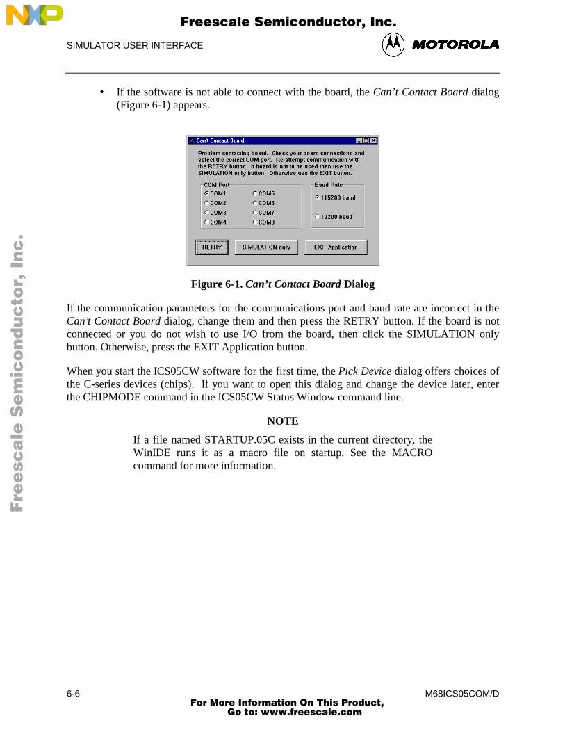
SIMULATOR USER INTERFACE
M68ICS05COM/D6-6
• If the software is not able to connect with the board, the Can’t Contact Board dialog(Figure 6-1) appears.
Figure 6-1. Can’t Contact Board Dialog
If the communication parameters for the communications port and baud rate are incorrect in theCan’t Contact Board dialog, change them and then press the RETRY button. If the board is notconnected or you do not wish to use I/O from the board, then click the SIMULATION onlybutton. Otherwise, press the EXIT Application button.
When you start the ICS05CW software for the first time, the Pick Device dialog offers choices ofthe C-series devices (chips). If you want to open this dialog and change the device later, enterthe CHIPMODE command in the ICS05CW Status Window command line.
NOTE
If a file named STARTUP.05C exists in the current directory, theWinIDE runs it as a macro file on startup. See the MACROcommand for more information.
Fre
esc
ale
Se
mic
on
du
cto
r, I
Freescale Semiconductor, Inc.
For More Information On This Product, Go to: www.freescale.com
nc
...
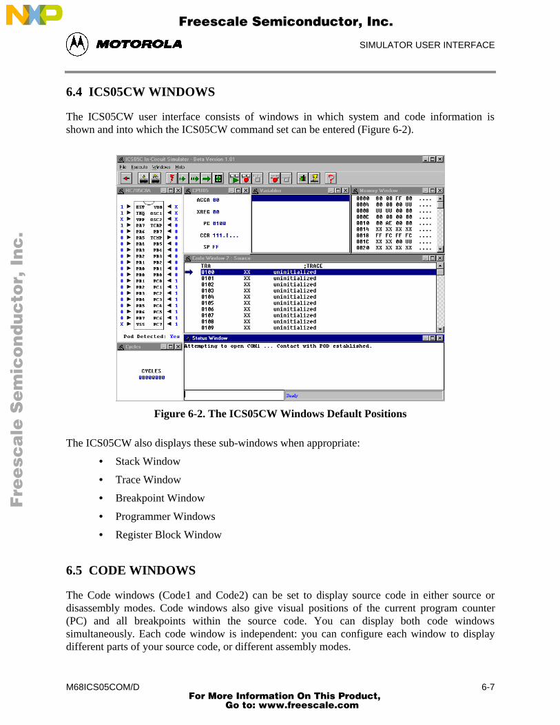
SIMULATOR USER INTERFACE
M68ICS05COM/D 6-7
6.4 ICS05CW WINDOWS
The ICS05CW user interface consists of windows in which system and code information isshown and into which the ICS05CW command set can be entered (Figure 6-2).
Figure 6-2. The ICS05CW Windows Default Positions
The ICS05CW also displays these sub-windows when appropriate:
• Stack Window
• Trace Window
• Breakpoint Window
• Programmer Windows
• Register Block Window
6.5 CODE WINDOWS
The Code windows (Code1 and Code2) can be set to display source code in either source ordisassembly modes. Code windows also give visual positions of the current program counter(PC) and all breakpoints within the source code. You can display both code windowssimultaneously. Each code window is independent: you can configure each window to displaydifferent parts of your source code, or different assembly modes.
Fre
esc
ale
Se
mic
on
du
cto
r, I
Freescale Semiconductor, Inc.
For More Information On This Product, Go to: www.freescale.com
nc
...
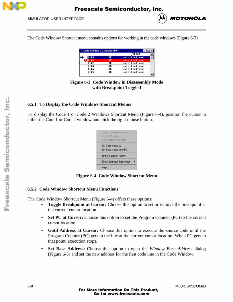
SIMULATOR USER INTERFACE
M68ICS05COM/D6-8
The Code Window Shortcut menu contains options for working in the code windows (Figure 6-3).
Figure 6-3. Code Window in Disassembly Modewith Breakpoint Toggled
6.5.1 To Display the Code Windows Shortcut Menus
To display the Code 1 or Code 2 Windows Shortcut Menu (Figure 6-4), position the cursor ineither the Code1 or Code2 window and click the right mouse button.
Figure 6-4. Code Window Shortcut Menu
6.5.2 Code Window Shortcut Menu Functions
The Code Window Shortcut Menu (Figure 6-4) offers these options:• Toggle Breakpoint at Cursor: Choose this option to set or remove the breakpoint at
the current cursor location.
• Set PC at Cursor: Choose this option to set the Program Counter (PC) to the currentcursor location.
• Gotil Address at Cursor: Choose this option to execute the source code until theProgram Counter (PC) gets to the line at the current cursor location. When PC gets tothat point, execution stops.
• Set Base Address: Choose this option to open the Window Base Address dialog(Figure 6-5) and set the new address for the first code line in the Code Window.
Fre
esc
ale
Se
mic
on
du
cto
r, I
Freescale Semiconductor, Inc.
For More Information On This Product, Go to: www.freescale.com
nc
...
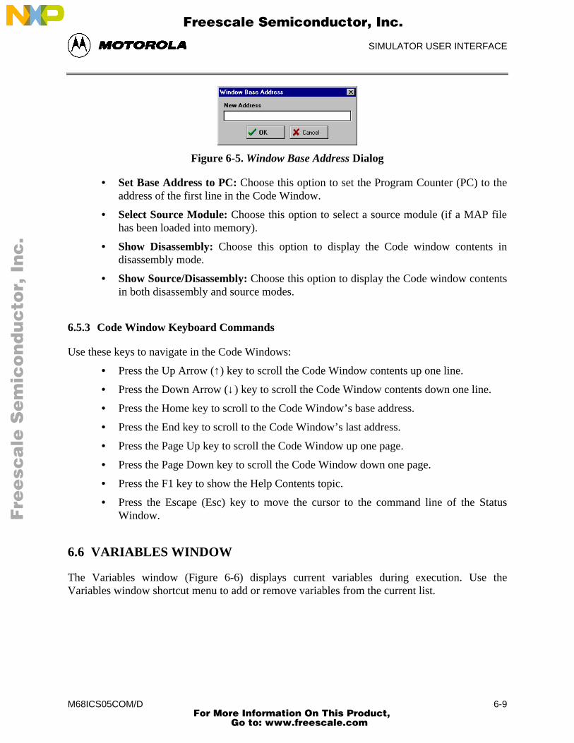
SIMULATOR USER INTERFACE
M68ICS05COM/D 6-9
Figure 6-5. Window Base Address Dialog
• Set Base Address to PC: Choose this option to set the Program Counter (PC) to theaddress of the first line in the Code Window.
• Select Source Module: Choose this option to select a source module (if a MAP filehas been loaded into memory).
• Show Disassembly: Choose this option to display the Code window contents indisassembly mode.
• Show Source/Disassembly: Choose this option to display the Code window contentsin both disassembly and source modes.
6.5.3 Code Window Keyboard Commands
Use these keys to navigate in the Code Windows:
• Press the Up Arrow (↑) key to scroll the Code Window contents up one line.
• Press the Down Arrow (↓) key to scroll the Code Window contents down one line.
• Press the Home key to scroll to the Code Window’s base address.
• Press the End key to scroll to the Code Window’s last address.
• Press the Page Up key to scroll the Code Window up one page.
• Press the Page Down key to scroll the Code Window down one page.
• Press the F1 key to show the Help Contents topic.
• Press the Escape (Esc) key to move the cursor to the command line of the StatusWindow.
6.6 VARIABLES WINDOW
The Variables window (Figure 6-6) displays current variables during execution. Use theVariables window shortcut menu to add or remove variables from the current list.
Fre
esc
ale
Se
mic
on
du
cto
r, I
Freescale Semiconductor, Inc.
For More Information On This Product, Go to: www.freescale.com
nc
...
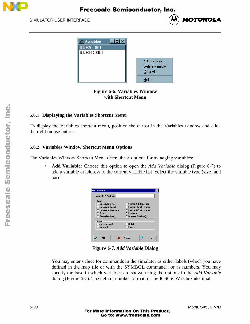
SIMULATOR USER INTERFACE
M68ICS05COM/D6-10
Figure 6-6. Variables Windowwith Shortcut Menu
6.6.1 Displaying the Variables Shortcut Menu
To display the Variables shortcut menu, position the cursor in the Variables window and clickthe right mouse button.
6.6.2 Variables Window Shortcut Menu Options
The Variables Window Shortcut Menu offers these options for managing variables:
• Add Variable: Choose this option to open the Add Variable dialog (Figure 6-7) toadd a variable or address to the current variable list. Select the variable type (size) andbase.
Figure 6-7. Add Variable Dialog
You may enter values for commands in the simulator as either labels (which you havedefined in the map file or with the SYMBOL command), or as numbers. You mayspecify the base in which variables are shown using the options in the Add Variabledialog (Figure 6-7). The default number format for the ICS05CW is hexadecimal.
Fre
esc
ale
Se
mic
on
du
cto
r, I
Freescale Semiconductor, Inc.
For More Information On This Product, Go to: www.freescale.com
nc
...
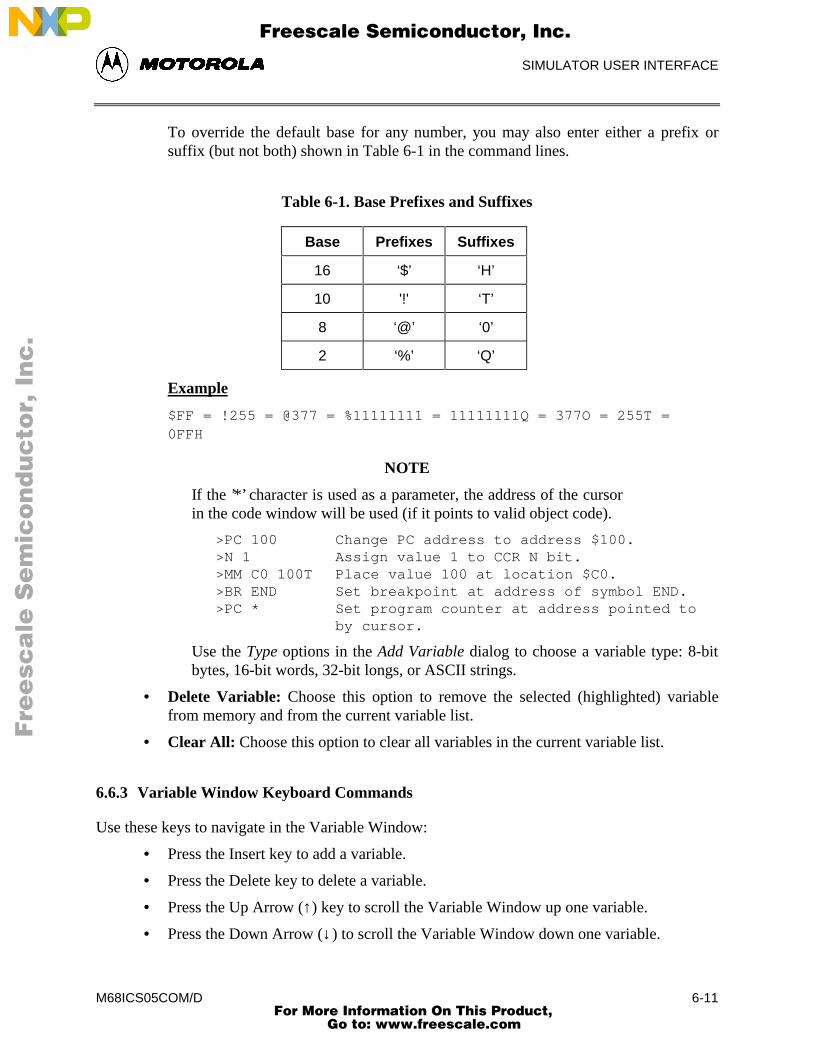
SIMULATOR USER INTERFACE
M68ICS05COM/D 6-11
To override the default base for any number, you may also enter either a prefix orsuffix (but not both) shown in Table 6-1 in the command lines.
Table 6-1. Base Prefixes and Suffixes
Base Prefixes Suffixes
16 ‘$’ ‘H’
10 '!' ‘T’
8 ‘@’ ‘0’
2 ‘%’ ‘Q’
Example
$FF = !255 = @377 = %11111111 = 11111111Q = 377O = 255T =0FFH
NOTE
If the ’*’ character is used as a parameter, the address of the cursorin the code window will be used (if it points to valid object code).
>PC 100 Change PC address to address $100.>N 1 Assign value 1 to CCR N bit.>MM C0 100T Place value 100 at location $C0.>BR END Set breakpoint at address of symbol END.>PC * Set program counter at address pointed to
by cursor.
Use the Type options in the Add Variable dialog to choose a variable type: 8-bitbytes, 16-bit words, 32-bit longs, or ASCII strings.
• Delete Variable: Choose this option to remove the selected (highlighted) variablefrom memory and from the current variable list.
• Clear All: Choose this option to clear all variables in the current variable list.
6.6.3 Variable Window Keyboard Commands
Use these keys to navigate in the Variable Window:
• Press the Insert key to add a variable.
• Press the Delete key to delete a variable.
• Press the Up Arrow (↑) key to scroll the Variable Window up one variable.
• Press the Down Arrow (↓) to scroll the Variable Window down one variable.
Fre
esc
ale
Se
mic
on
du
cto
r, I
Freescale Semiconductor, Inc.
For More Information On This Product, Go to: www.freescale.com
nc
...
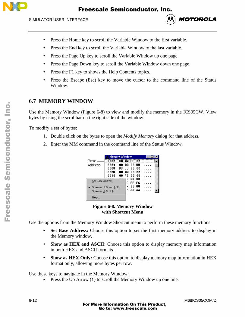
SIMULATOR USER INTERFACE
M68ICS05COM/D6-12
• Press the Home key to scroll the Variable Window to the first variable.
• Press the End key to scroll the Variable Window to the last variable.
• Press the Page Up key to scroll the Variable Window up one page.
• Press the Page Down key to scroll the Variable Window down one page.
• Press the F1 key to shows the Help Contents topics.
• Press the Escape (Esc) key to move the cursor to the command line of the StatusWindow.
6.7 MEMORY WINDOW
Use the Memory Window (Figure 6-8) to view and modify the memory in the ICS05CW. Viewbytes by using the scrollbar on the right side of the window.
To modify a set of bytes:
1. Double click on the bytes to open the Modify Memory dialog for that address.
2. Enter the MM command in the command line of the Status Window.
Figure 6-8. Memory Windowwith Shortcut Menu
Use the options from the Memory Window Shortcut menu to perform these memory functions:
• Set Base Address: Choose this option to set the first memory address to display inthe Memory window.
• Show as HEX and ASCII: Choose this option to display memory map informationin both HEX and ASCII formats.
• Show as HEX Only: Choose this option to display memory map information in HEXformat only, allowing more bytes per row.
Use these keys to navigate in the Memory Window:• Press the Up Arrow (↑) to scroll the Memory Window up one line.
Fre
esc
ale
Se
mic
on
du
cto
r, I
Freescale Semiconductor, Inc.
For More Information On This Product, Go to: www.freescale.com
nc
...
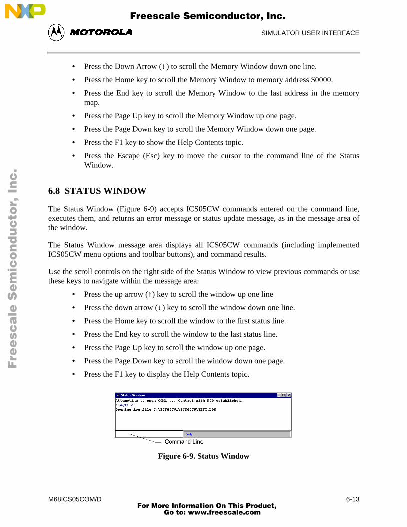
SIMULATOR USER INTERFACE
M68ICS05COM/D 6-13
• Press the Down Arrow (↓) to scroll the Memory Window down one line.
• Press the Home key to scroll the Memory Window to memory address $0000.
• Press the End key to scroll the Memory Window to the last address in the memorymap.
• Press the Page Up key to scroll the Memory Window up one page.
• Press the Page Down key to scroll the Memory Window down one page.
• Press the F1 key to show the Help Contents topic.
• Press the Escape (Esc) key to move the cursor to the command line of the StatusWindow.
6.8 STATUS WINDOW
The Status Window (Figure 6-9) accepts ICS05CW commands entered on the command line,executes them, and returns an error message or status update message, as in the message area ofthe window.
The Status Window message area displays all ICS05CW commands (including implementedICS05CW menu options and toolbar buttons), and command results.
Use the scroll controls on the right side of the Status Window to view previous commands or usethese keys to navigate within the message area:
• Press the up arrow (↑) key to scroll the window up one line
• Press the down arrow (↓) key to scroll the window down one line.
• Press the Home key to scroll the window to the first status line.
• Press the End key to scroll the window to the last status line.
• Press the Page Up key to scroll the window up one page.
• Press the Page Down key to scroll the window down one page.
• Press the F1 key to display the Help Contents topic.
Figure 6-9. Status Window
Fre
esc
ale
Se
mic
on
du
cto
r, I
Freescale Semiconductor, Inc.
For More Information On This Product, Go to: www.freescale.com
nc
...
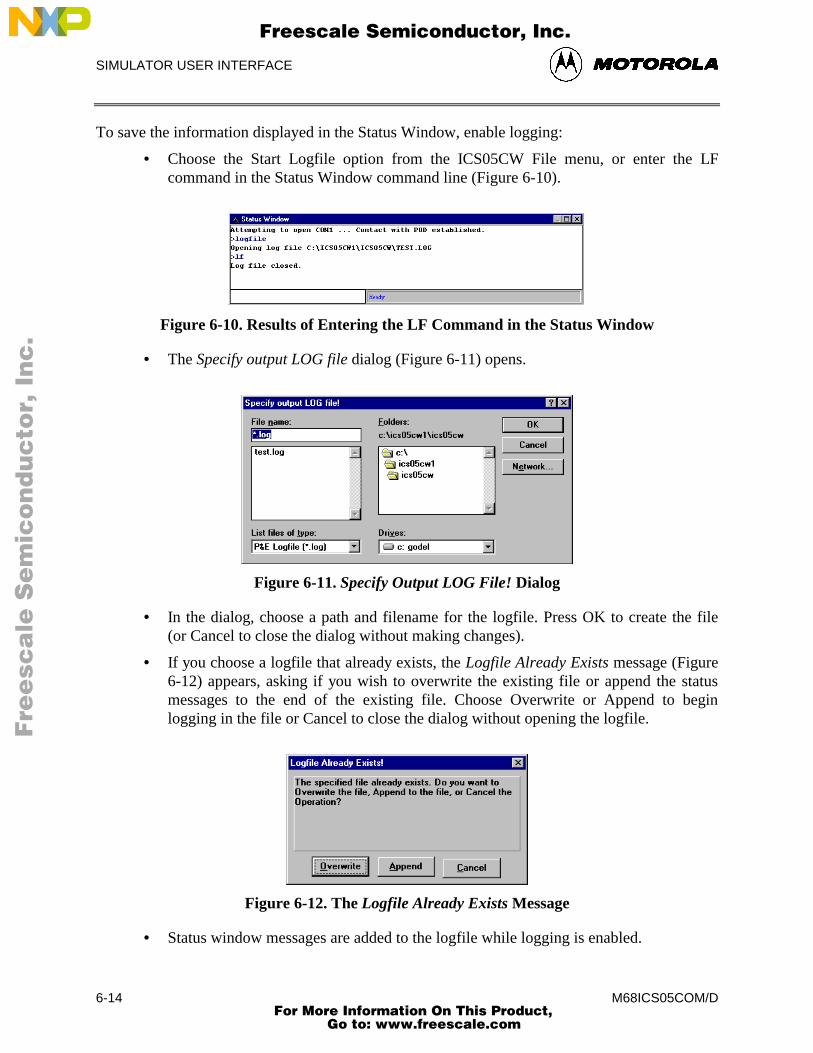
SIMULATOR USER INTERFACE
M68ICS05COM/D6-14
To save the information displayed in the Status Window, enable logging:
• Choose the Start Logfile option from the ICS05CW File menu, or enter the LFcommand in the Status Window command line (Figure 6-10).
Figure 6-10. Results of Entering the LF Command in the Status Window
• The Specify output LOG file dialog (Figure 6-11) opens.
Figure 6-11. Specify Output LOG File! Dialog
• In the dialog, choose a path and filename for the logfile. Press OK to create the file(or Cancel to close the dialog without making changes).
• If you choose a logfile that already exists, the Logfile Already Exists message (Figure6-12) appears, asking if you wish to overwrite the existing file or append the statusmessages to the end of the existing file. Choose Overwrite or Append to beginlogging in the file or Cancel to close the dialog without opening the logfile.
Figure 6-12. The Logfile Already Exists Message
• Status window messages are added to the logfile while logging is enabled.
Fre
esc
ale
Se
mic
on
du
cto
r, I
Freescale Semiconductor, Inc.
For More Information On This Product, Go to: www.freescale.com
nc
...
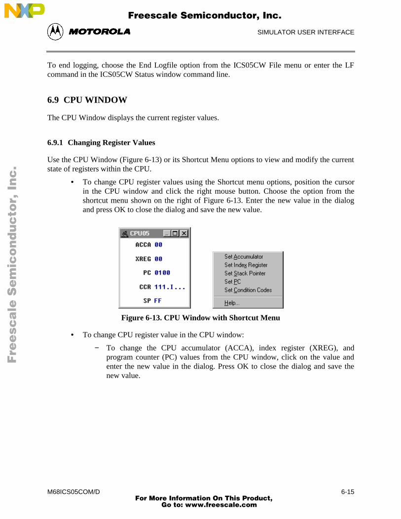
SIMULATOR USER INTERFACE
M68ICS05COM/D 6-15
To end logging, choose the End Logfile option from the ICS05CW File menu or enter the LFcommand in the ICS05CW Status window command line.
6.9 CPU WINDOW
The CPU Window displays the current register values.
6.9.1 Changing Register Values
Use the CPU Window (Figure 6-13) or its Shortcut Menu options to view and modify the currentstate of registers within the CPU.
• To change CPU register values using the Shortcut menu options, position the cursorin the CPU window and click the right mouse button. Choose the option from theshortcut menu shown on the right of Figure 6-13. Enter the new value in the dialogand press OK to close the dialog and save the new value.
Figure 6-13. CPU Window with Shortcut Menu
• To change CPU register value in the CPU window:
− To change the CPU accumulator (ACCA), index register (XREG), andprogram counter (PC) values from the CPU window, click on the value andenter the new value in the dialog. Press OK to close the dialog and save thenew value.
Fre
esc
ale
Se
mic
on
du
cto
r, I
Freescale Semiconductor, Inc.
For More Information On This Product, Go to: www.freescale.com
nc
...
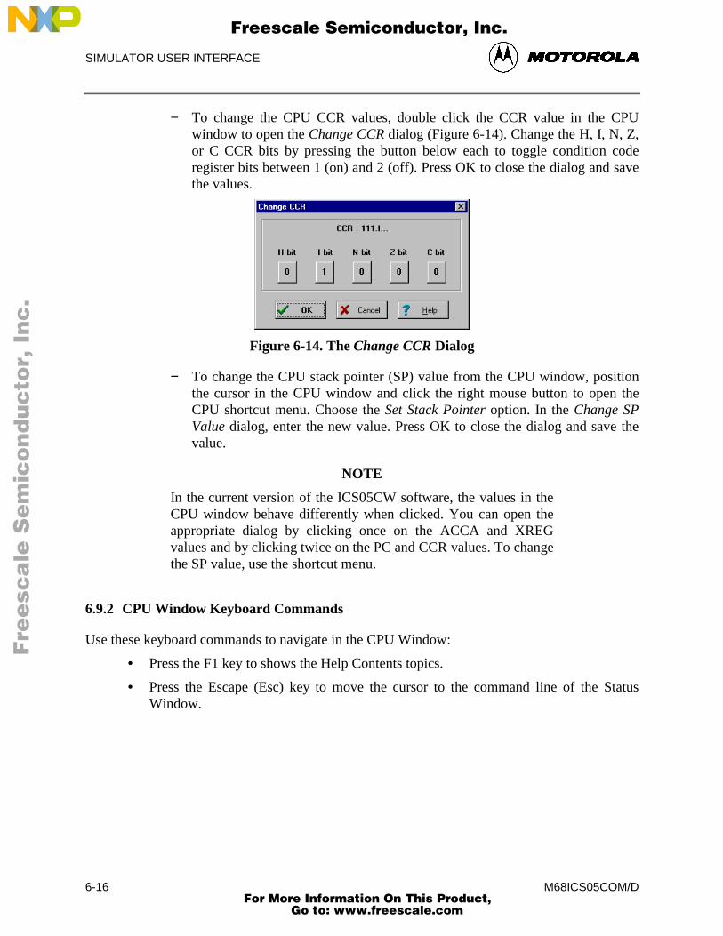
SIMULATOR USER INTERFACE
M68ICS05COM/D6-16
− To change the CPU CCR values, double click the CCR value in the CPUwindow to open the Change CCR dialog (Figure 6-14). Change the H, I, N, Z,or C CCR bits by pressing the button below each to toggle condition coderegister bits between 1 (on) and 2 (off). Press OK to close the dialog and savethe values.
Figure 6-14. The Change CCR Dialog
− To change the CPU stack pointer (SP) value from the CPU window, positionthe cursor in the CPU window and click the right mouse button to open theCPU shortcut menu. Choose the Set Stack Pointer option. In the Change SPValue dialog, enter the new value. Press OK to close the dialog and save thevalue.
NOTE
In the current version of the ICS05CW software, the values in theCPU window behave differently when clicked. You can open theappropriate dialog by clicking once on the ACCA and XREGvalues and by clicking twice on the PC and CCR values. To changethe SP value, use the shortcut menu.
6.9.2 CPU Window Keyboard Commands
Use these keyboard commands to navigate in the CPU Window:
• Press the F1 key to shows the Help Contents topics.
• Press the Escape (Esc) key to move the cursor to the command line of the StatusWindow.
Fre
esc
ale
Se
mic
on
du
cto
r, I
Freescale Semiconductor, Inc.
For More Information On This Product, Go to: www.freescale.com
nc
...
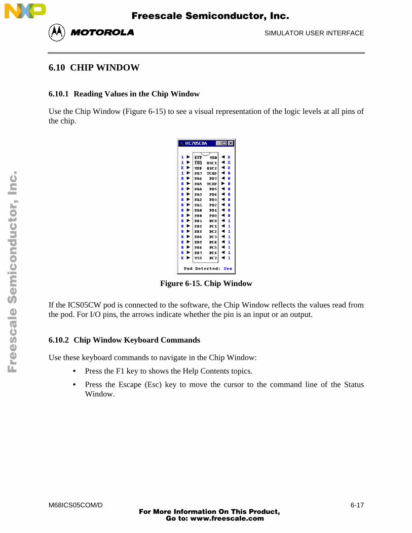
SIMULATOR USER INTERFACE
M68ICS05COM/D 6-17
6.10 CHIP WINDOW
6.10.1 Reading Values in the Chip Window
Use the Chip Window (Figure 6-15) to see a visual representation of the logic levels at all pins ofthe chip.
Figure 6-15. Chip Window
If the ICS05CW pod is connected to the software, the Chip Window reflects the values read fromthe pod. For I/O pins, the arrows indicate whether the pin is an input or an output.
6.10.2 Chip Window Keyboard Commands
Use these keyboard commands to navigate in the Chip Window:
• Press the F1 key to shows the Help Contents topics.
• Press the Escape (Esc) key to move the cursor to the command line of the StatusWindow.
Fre
esc
ale
Se
mic
on
du
cto
r, I
Freescale Semiconductor, Inc.
For More Information On This Product, Go to: www.freescale.com
nc
...
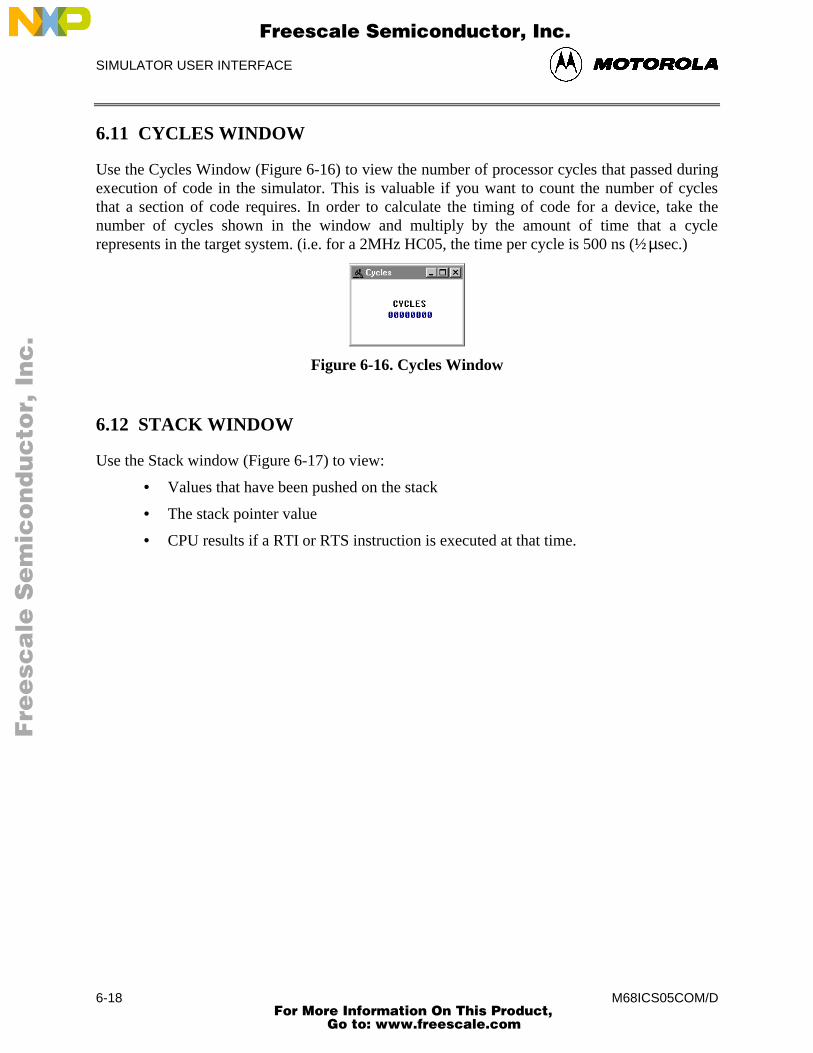
SIMULATOR USER INTERFACE
M68ICS05COM/D6-18
6.11 CYCLES WINDOW
Use the Cycles Window (Figure 6-16) to view the number of processor cycles that passed duringexecution of code in the simulator. This is valuable if you want to count the number of cyclesthat a section of code requires. In order to calculate the timing of code for a device, take thenumber of cycles shown in the window and multiply by the amount of time that a cyclerepresents in the target system. (i.e. for a 2MHz HC05, the time per cycle is 500 ns (½ µsec.)
Figure 6-16. Cycles Window
6.12 STACK WINDOW
Use the Stack window (Figure 6-17) to view:
• Values that have been pushed on the stack
• The stack pointer value
• CPU results if a RTI or RTS instruction is executed at that time.
Fre
esc
ale
Se
mic
on
du
cto
r, I
Freescale Semiconductor, Inc.
For More Information On This Product, Go to: www.freescale.com
nc
...
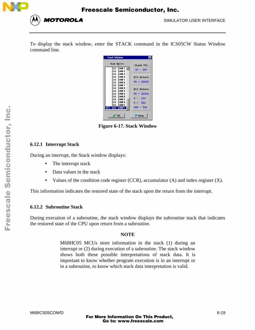
SIMULATOR USER INTERFACE
M68ICS05COM/D 6-19
To display the stack window, enter the STACK command in the ICS05CW Status Windowcommand line.
Figure 6-17. Stack Window
6.12.1 Interrupt Stack
During an interrupt, the Stack window displays:
• The interrupt stack
• Data values in the stack
• Values of the condition code register (CCR), accumulator (A) and index register (X).
This information indicates the restored state of the stack upon the return from the interrupt.
6.12.2 Subroutine Stack
During execution of a subroutine, the stack window displays the subroutine stack that indicatesthe restored state of the CPU upon return from a subroutine.
NOTE
M68HC05 MCUs store information in the stack (1) during aninterrupt or (2) during execution of a subroutine. The stack windowshows both these possible interpretations of stack data. It isimportant to know whether program execution is in an interrupt orin a subroutine, to know which stack data interpretation is valid.
Fre
esc
ale
Se
mic
on
du
cto
r, I
Freescale Semiconductor, Inc.
For More Information On This Product, Go to: www.freescale.com
nc
...
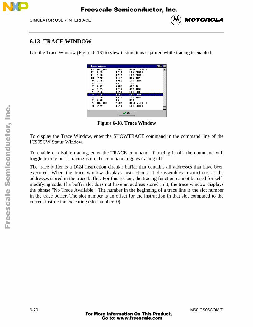
SIMULATOR USER INTERFACE
M68ICS05COM/D6-20
6.13 TRACE WINDOW
Use the Trace Window (Figure 6-18) to view instructions captured while tracing is enabled.
Figure 6-18. Trace Window
To display the Trace Window, enter the SHOWTRACE command in the command line of theICS05CW Status Window.
To enable or disable tracing, enter the TRACE command. If tracing is off, the command willtoggle tracing on; if tracing is on, the command toggles tracing off.
The trace buffer is a 1024 instruction circular buffer that contains all addresses that have beenexecuted. When the trace window displays instructions, it disassembles instructions at theaddresses stored in the trace buffer. For this reason, the tracing function cannot be used for self-modifying code. If a buffer slot does not have an address stored in it, the trace window displaysthe phrase "No Trace Available". The number in the beginning of a trace line is the slot numberin the trace buffer. The slot number is an offset for the instruction in that slot compared to thecurrent instruction executing (slot number=0).
Fre
esc
ale
Se
mic
on
du
cto
r, I
Freescale Semiconductor, Inc.
For More Information On This Product, Go to: www.freescale.com
nc
...
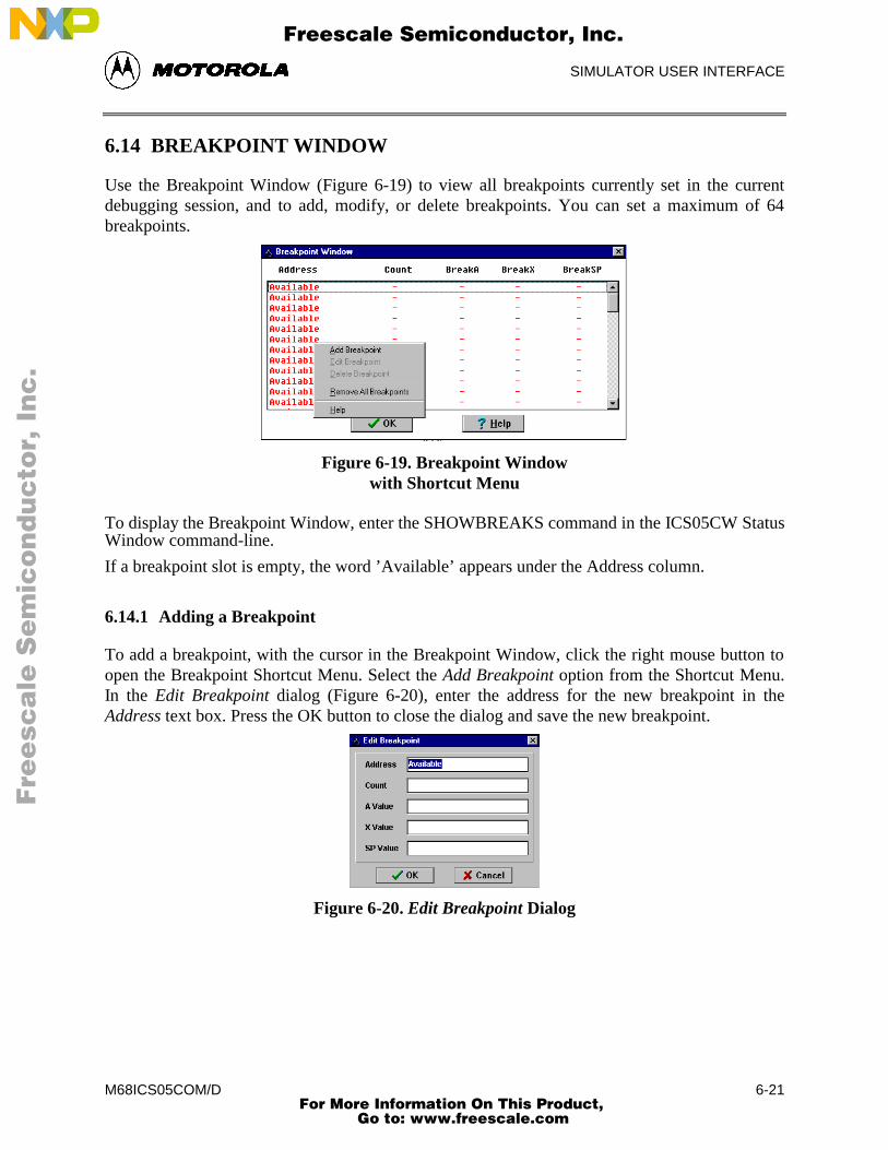
SIMULATOR USER INTERFACE
M68ICS05COM/D 6-21
6.14 BREAKPOINT WINDOW
Use the Breakpoint Window (Figure 6-19) to view all breakpoints currently set in the currentdebugging session, and to add, modify, or delete breakpoints. You can set a maximum of 64breakpoints.
Figure 6-19. Breakpoint Windowwith Shortcut Menu
To display the Breakpoint Window, enter the SHOWBREAKS command in the ICS05CW StatusWindow command-line.
If a breakpoint slot is empty, the word ’Available’ appears under the Address column.
6.14.1 Adding a Breakpoint
To add a breakpoint, with the cursor in the Breakpoint Window, click the right mouse button toopen the Breakpoint Shortcut Menu. Select the Add Breakpoint option from the Shortcut Menu.In the Edit Breakpoint dialog (Figure 6-20), enter the address for the new breakpoint in theAddress text box. Press the OK button to close the dialog and save the new breakpoint.
Figure 6-20. Edit Breakpoint Dialog
Fre
esc
ale
Se
mic
on
du
cto
r, I
Freescale Semiconductor, Inc.
For More Information On This Product, Go to: www.freescale.com
nc
...
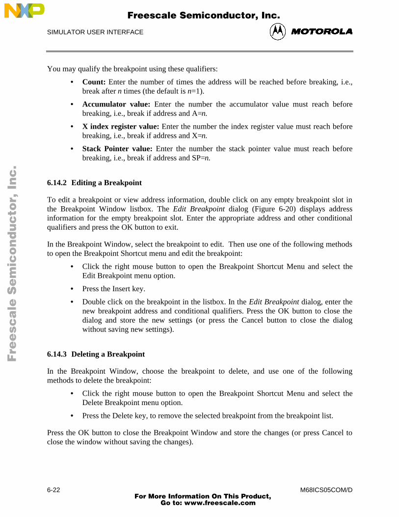
SIMULATOR USER INTERFACE
M68ICS05COM/D6-22
You may qualify the breakpoint using these qualifiers:
• Count: Enter the number of times the address will be reached before breaking, i.e.,break after n times (the default is n=1).
• Accumulator value: Enter the number the accumulator value must reach beforebreaking, i.e., break if address and A=n.
• X index register value: Enter the number the index register value must reach beforebreaking, i.e., break if address and X=n.
• Stack Pointer value: Enter the number the stack pointer value must reach beforebreaking, i.e., break if address and SP=n.
6.14.2 Editing a Breakpoint
To edit a breakpoint or view address information, double click on any empty breakpoint slot inthe Breakpoint Window listbox. The Edit Breakpoint dialog (Figure 6-20) displays addressinformation for the empty breakpoint slot. Enter the appropriate address and other conditionalqualifiers and press the OK button to exit.
In the Breakpoint Window, select the breakpoint to edit. Then use one of the following methodsto open the Breakpoint Shortcut menu and edit the breakpoint:
• Click the right mouse button to open the Breakpoint Shortcut Menu and select theEdit Breakpoint menu option.
• Press the Insert key.
• Double click on the breakpoint in the listbox. In the Edit Breakpoint dialog, enter thenew breakpoint address and conditional qualifiers. Press the OK button to close thedialog and store the new settings (or press the Cancel button to close the dialogwithout saving new settings).
6.14.3 Deleting a Breakpoint
In the Breakpoint Window, choose the breakpoint to delete, and use one of the followingmethods to delete the breakpoint:
• Click the right mouse button to open the Breakpoint Shortcut Menu and select theDelete Breakpoint menu option.
• Press the Delete key, to remove the selected breakpoint from the breakpoint list.
Press the OK button to close the Breakpoint Window and store the changes (or press Cancel toclose the window without saving the changes).
Fre
esc
ale
Se
mic
on
du
cto
r, I
Freescale Semiconductor, Inc.
For More Information On This Product, Go to: www.freescale.com
nc
...
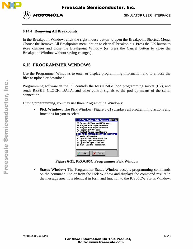
SIMULATOR USER INTERFACE
M68ICS05COM/D 6-23
6.14.4 Removing All Breakpoints
In the Breakpoint Window, click the right mouse button to open the Breakpoint Shortcut Menu.Choose the Remove All Breakpoints menu option to clear all breakpoints. Press the OK button tostore changes and close the Breakpoint Window (or press the Cancel button to close theBreakpoint Window without saving changes).
6.15 PROGRAMMER WINDOWS
Use the Programmer Windows to enter or display programming information and to choose thefiles to upload or download.
Programming software in the PC controls the M68ICS05C pod programming socket (U2), andsends RESET, CLOCK, DATA, and other control signals to the pod by means of the serialconnection.
During programming, you may use three Programming Windows:
• Pick Window: The Pick Window (Figure 6-21) displays all programming actions andfunctions for you to select.
Figure 6-21. PROG05C Programmer Pick Window
• Status Window: The Programmer Status Window accepts programming commandson the command line or from the Pick Window and displays the command results inthe message area. It is identical in form and function to the ICS05CW Status Window.
Fre
esc
ale
Se
mic
on
du
cto
r, I
Freescale Semiconductor, Inc.
For More Information On This Product, Go to: www.freescale.com
nc
...
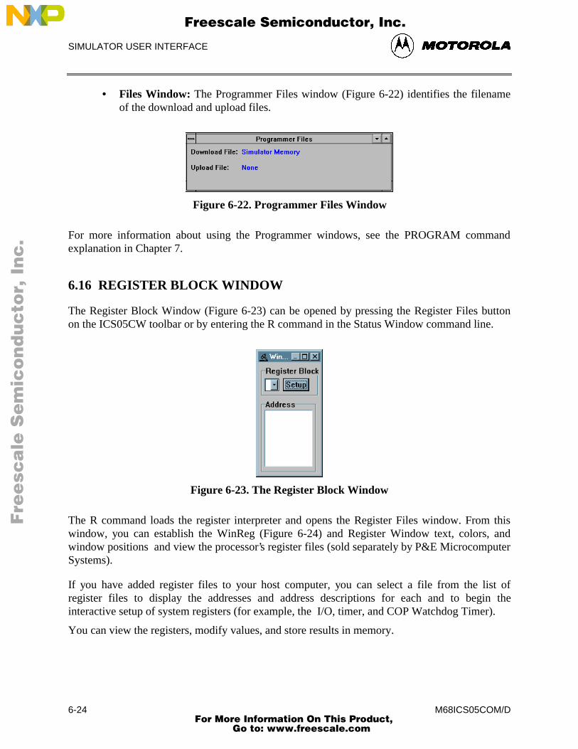
SIMULATOR USER INTERFACE
M68ICS05COM/D6-24
• Files Window: The Programmer Files window (Figure 6-22) identifies the filenameof the download and upload files.
Figure 6-22. Programmer Files Window
For more information about using the Programmer windows, see the PROGRAM commandexplanation in Chapter 7.
6.16 REGISTER BLOCK WINDOW
The Register Block Window (Figure 6-23) can be opened by pressing the Register Files buttonon the ICS05CW toolbar or by entering the R command in the Status Window command line.
Figure 6-23. The Register Block Window
The R command loads the register interpreter and opens the Register Files window. From thiswindow, you can establish the WinReg (Figure 6-24) and Register Window text, colors, andwindow positions and view the processor’s register files (sold separately by P&E MicrocomputerSystems).
If you have added register files to your host computer, you can select a file from the list ofregister files to display the addresses and address descriptions for each and to begin theinteractive setup of system registers (for example, the I/O, timer, and COP Watchdog Timer).
You can view the registers, modify values, and store results in memory.
Fre
esc
ale
Se
mic
on
du
cto
r, I
Freescale Semiconductor, Inc.
For More Information On This Product, Go to: www.freescale.com
nc
...
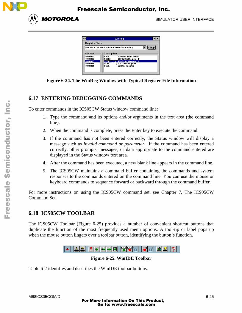
SIMULATOR USER INTERFACE
M68ICS05COM/D 6-25
Figure 6-24. The WinReg Window with Typical Register File Information
6.17 ENTERING DEBUGGING COMMANDS
To enter commands in the ICS05CW Status window command line:
1. Type the command and its options and/or arguments in the text area (the commandline).
2. When the command is complete, press the Enter key to execute the command.
3. If the command has not been entered correctly, the Status window will display amessage such as Invalid command or parameter. If the command has been enteredcorrectly, other prompts, messages, or data appropriate to the command entered aredisplayed in the Status window text area.
4. After the command has been executed, a new blank line appears in the command line.
5. The ICS05CW maintains a command buffer containing the commands and systemresponses to the commands entered on the command line. You can use the mouse orkeyboard commands to sequence forward or backward through the command buffer.
For more instructions on using the ICS05CW command set, see Chapter 7, The ICS05CWCommand Set.
6.18 ICS05CW TOOLBAR
The ICS05CW Toolbar (Figure 6-25) provides a number of convenient shortcut buttons thatduplicate the function of the most frequently used menu options. A tool-tip or label pops upwhen the mouse button lingers over a toolbar button, identifying the button’s function.
Figure 6-25. WinIDE Toolbar
Table 6-2 identifies and describes the WinIDE toolbar buttons.
Fre
esc
ale
Se
mic
on
du
cto
r, I
Freescale Semiconductor, Inc.
For More Information On This Product, Go to: www.freescale.com
nc
...
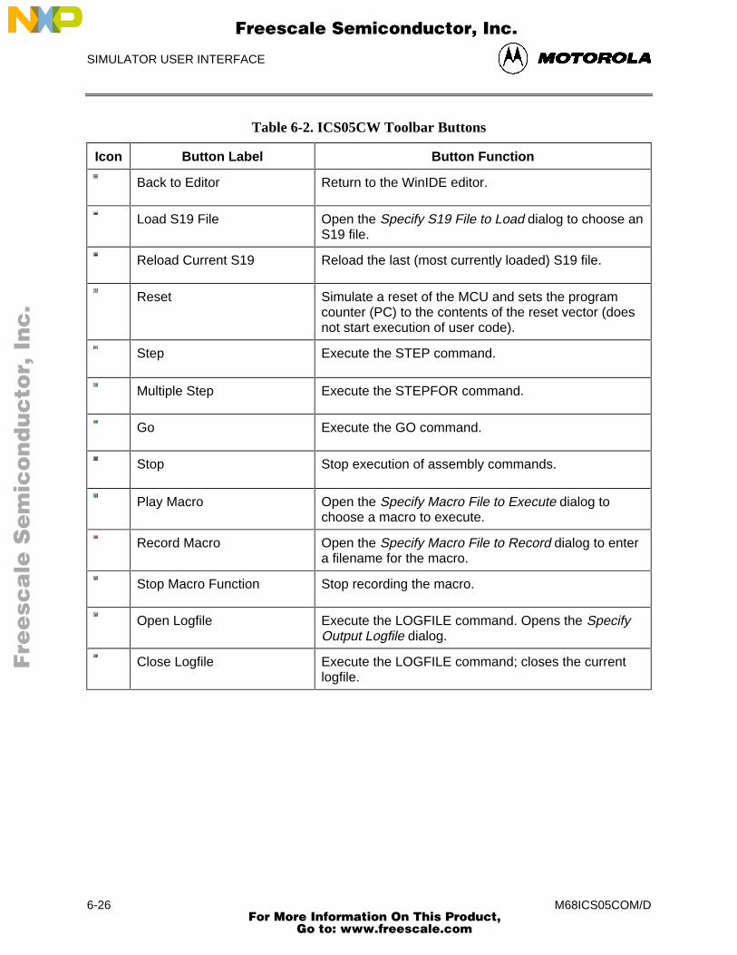
SIMULATOR USER INTERFACE
M68ICS05COM/D6-26
Table 6-2. ICS05CW Toolbar Buttons
Icon Button Label Button Function
Back to Editor Return to the WinIDE editor.
Load S19 File Open the Specify S19 File to Load dialog to choose anS19 file.
Reload Current S19 Reload the last (most currently loaded) S19 file.
Reset Simulate a reset of the MCU and sets the programcounter (PC) to the contents of the reset vector (doesnot start execution of user code).
Step Execute the STEP command.
Multiple Step Execute the STEPFOR command.
Go Execute the GO command.
Stop Stop execution of assembly commands.
Play Macro Open the Specify Macro File to Execute dialog tochoose a macro to execute.
Record Macro Open the Specify Macro File to Record dialog to entera filename for the macro.
Stop Macro Function Stop recording the macro.
Open Logfile Execute the LOGFILE command. Opens the SpecifyOutput Logfile dialog.
Close Logfile Execute the LOGFILE command; closes the currentlogfile.
Fre
esc
ale
Se
mic
on
du
cto
r, I
Freescale Semiconductor, Inc.
For More Information On This Product, Go to: www.freescale.com
nc
...
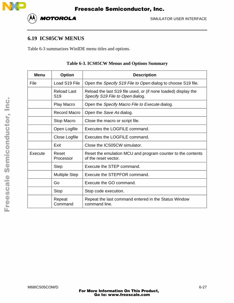
SIMULATOR USER INTERFACE
M68ICS05COM/D 6-27
6.19 ICS05CW MENUS
Table 6-3 summarizes WinIDE menu titles and options.
Table 6-3. ICS05CW Menus and Options Summary
Menu Option Description
File Load S19 File Open the Specify S19 File to Open dialog to choose S19 file.
Reload LastS19
Reload the last S19 file used, or (if none loaded) display theSpecify S19 File to Open dialog.
Play Macro Open the Specify Macro File to Execute dialog.
Record Macro Open the Save As dialog.
Stop Macro Close the macro or script file.
Open Logfile Executes the LOGFILE command.
Close Logfile Executes the LOGFILE command.
Exit Close the ICS05CW simulator.
Execute ResetProcessor
Reset the emulation MCU and program counter to the contentsof the reset vector.
Step Execute the STEP command.
Multiple Step Execute the STEPFOR command.
Go Execute the GO command.
Stop Stop code execution.
RepeatCommand
Repeat the last command entered in the Status Windowcommand line.
Fre
esc
ale
Se
mic
on
du
cto
r, I
Freescale Semiconductor, Inc.
For More Information On This Product, Go to: www.freescale.com
nc
...
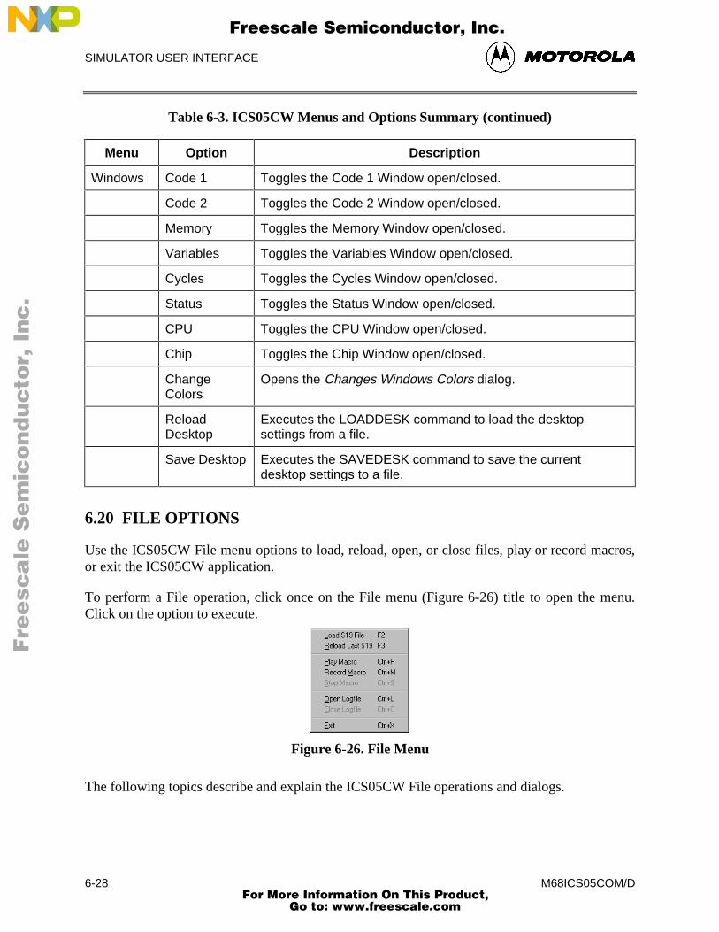
SIMULATOR USER INTERFACE
M68ICS05COM/D6-28
Table 6-3. ICS05CW Menus and Options Summary (continued)
Menu Option Description
Windows Code 1 Toggles the Code 1 Window open/closed.
Code 2 Toggles the Code 2 Window open/closed.
Memory Toggles the Memory Window open/closed.
Variables Toggles the Variables Window open/closed.
Cycles Toggles the Cycles Window open/closed.
Status Toggles the Status Window open/closed.
CPU Toggles the CPU Window open/closed.
Chip Toggles the Chip Window open/closed.
ChangeColors
Opens the Changes Windows Colors dialog.
ReloadDesktop
Executes the LOADDESK command to load the desktopsettings from a file.
Save Desktop Executes the SAVEDESK command to save the currentdesktop settings to a file.
6.20 FILE OPTIONS
Use the ICS05CW File menu options to load, reload, open, or close files, play or record macros,or exit the ICS05CW application.
To perform a File operation, click once on the File menu (Figure 6-26) title to open the menu.Click on the option to execute.
Figure 6-26. File Menu
The following topics describe and explain the ICS05CW File operations and dialogs.
Fre
esc
ale
Se
mic
on
du
cto
r, I
Freescale Semiconductor, Inc.
For More Information On This Product, Go to: www.freescale.com
nc
...
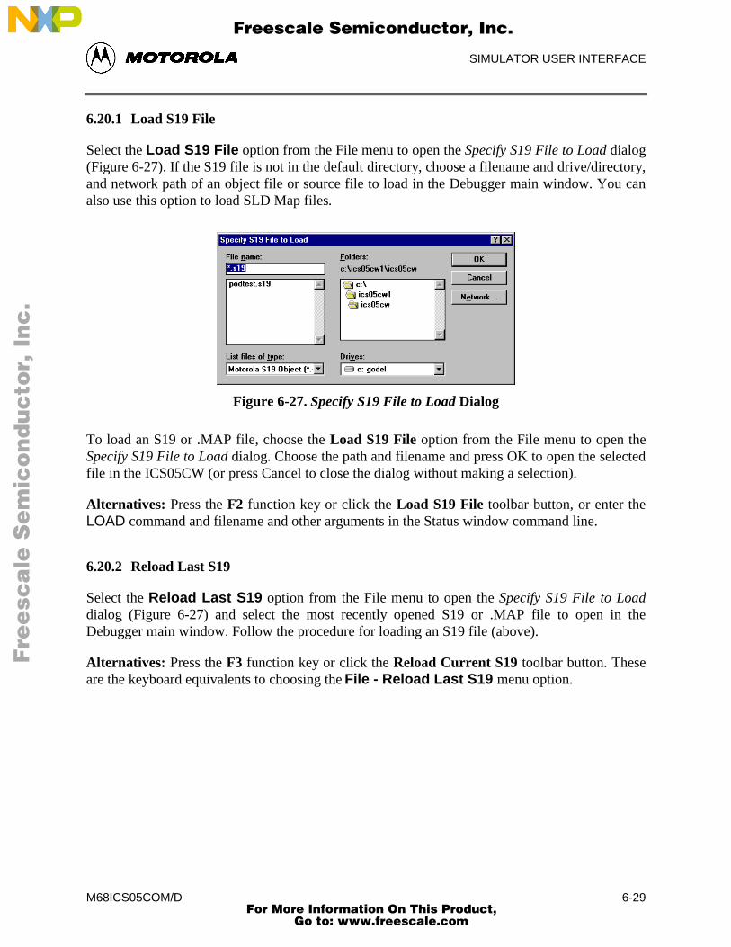
SIMULATOR USER INTERFACE
M68ICS05COM/D 6-29
6.20.1 Load S19 File
Select the Load S19 File option from the File menu to open the Specify S19 File to Load dialog(Figure 6-27). If the S19 file is not in the default directory, choose a filename and drive/directory,and network path of an object file or source file to load in the Debugger main window. You canalso use this option to load SLD Map files.
Figure 6-27. Specify S19 File to Load Dialog
To load an S19 or .MAP file, choose the Load S19 File option from the File menu to open theSpecify S19 File to Load dialog. Choose the path and filename and press OK to open the selectedfile in the ICS05CW (or press Cancel to close the dialog without making a selection).
Alternatives: Press the F2 function key or click the Load S19 File toolbar button, or enter theLOAD command and filename and other arguments in the Status window command line.
6.20.2 Reload Last S19
Select the Reload Last S19 option from the File menu to open the Specify S19 File to Loaddialog (Figure 6-27) and select the most recently opened S19 or .MAP file to open in theDebugger main window. Follow the procedure for loading an S19 file (above).
Alternatives: Press the F3 function key or click the Reload Current S19 toolbar button. Theseare the keyboard equivalents to choosing the File - Reload Last S19 menu option.
Fre
esc
ale
Se
mic
on
du
cto
r, I
Freescale Semiconductor, Inc.
For More Information On This Product, Go to: www.freescale.com
nc
...
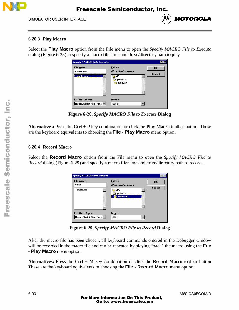
SIMULATOR USER INTERFACE
M68ICS05COM/D6-30
6.20.3 Play Macro
Select the Play Macro option from the File menu to open the Specify MACRO File to Executedialog (Figure 6-28) to specify a macro filename and drive/directory path to play.
Figure 6-28. Specify MACRO File to Execute Dialog
Alternatives: Press the Ctrl + P key combination or click the Play Macro toolbar button Theseare the keyboard equivalents to choosing the File - Play Macro menu option.
6.20.4 Record Macro
Select the Record Macro option from the File menu to open the Specify MACRO File toRecord dialog (Figure 6-29) and specify a macro filename and drive/directory path to record.
Figure 6-29. Specify MACRO File to Record Dialog
After the macro file has been chosen, all keyboard commands entered in the Debugger windowwill be recorded in the macro file and can be repeated by playing “back” the macro using the File- Play Macro menu option.
Alternatives: Press the Ctrl + M key combination or click the Record Macro toolbar buttonThese are the keyboard equivalents to choosing the File - Record Macro menu option.
Fre
esc
ale
Se
mic
on
du
cto
r, I
Freescale Semiconductor, Inc.
For More Information On This Product, Go to: www.freescale.com
nc
...
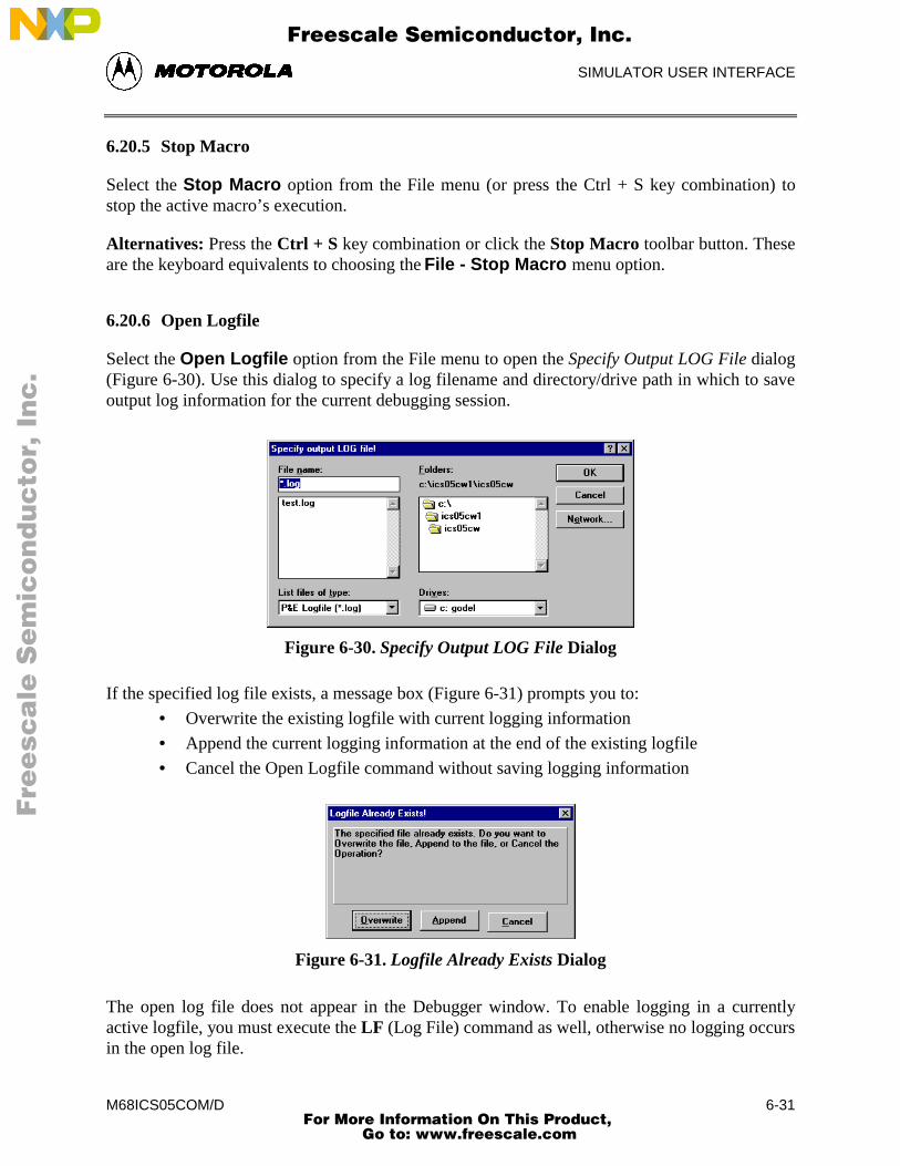
SIMULATOR USER INTERFACE
M68ICS05COM/D 6-31
6.20.5 Stop Macro
Select the Stop Macro option from the File menu (or press the Ctrl + S key combination) tostop the active macro’s execution.
Alternatives: Press the Ctrl + S key combination or click the Stop Macro toolbar button. Theseare the keyboard equivalents to choosing the File - Stop Macro menu option.
6.20.6 Open Logfile
Select the Open Logfile option from the File menu to open the Specify Output LOG File dialog(Figure 6-30). Use this dialog to specify a log filename and directory/drive path in which to saveoutput log information for the current debugging session.
Figure 6-30. Specify Output LOG File Dialog
If the specified log file exists, a message box (Figure 6-31) prompts you to:
• Overwrite the existing logfile with current logging information
• Append the current logging information at the end of the existing logfile
• Cancel the Open Logfile command without saving logging information
Figure 6-31. Logfile Already Exists Dialog
The open log file does not appear in the Debugger window. To enable logging in a currentlyactive logfile, you must execute the LF (Log File) command as well, otherwise no logging occursin the open log file.
Fre
esc
ale
Se
mic
on
du
cto
r, I
Freescale Semiconductor, Inc.
For More Information On This Product, Go to: www.freescale.com
nc
...
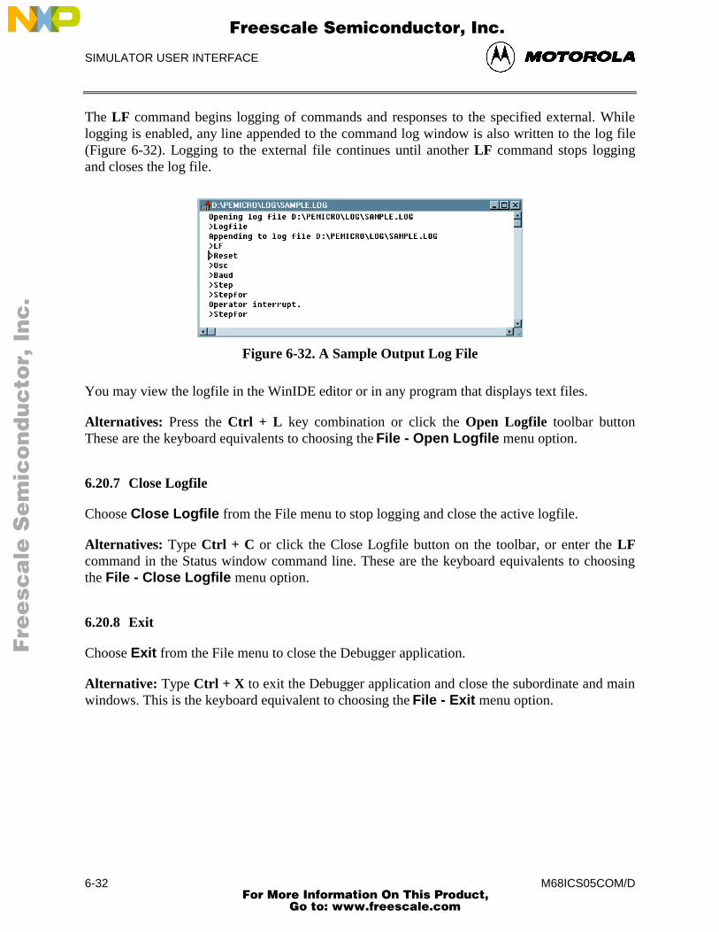
SIMULATOR USER INTERFACE
M68ICS05COM/D6-32
The LF command begins logging of commands and responses to the specified external. Whilelogging is enabled, any line appended to the command log window is also written to the log file(Figure 6-32). Logging to the external file continues until another LF command stops loggingand closes the log file.
Figure 6-32. A Sample Output Log File
You may view the logfile in the WinIDE editor or in any program that displays text files.
Alternatives: Press the Ctrl + L key combination or click the Open Logfile toolbar buttonThese are the keyboard equivalents to choosing the File - Open Logfile menu option.
6.20.7 Close Logfile
Choose Close Logfile from the File menu to stop logging and close the active logfile.
Alternatives: Type Ctrl + C or click the Close Logfile button on the toolbar, or enter the LFcommand in the Status window command line. These are the keyboard equivalents to choosingthe File - Close Logfile menu option.
6.20.8 Exit
Choose Exit from the File menu to close the Debugger application.
Alternative: Type Ctrl + X to exit the Debugger application and close the subordinate and mainwindows. This is the keyboard equivalent to choosing the File - Exit menu option.
Fre
esc
ale
Se
mic
on
du
cto
r, I
Freescale Semiconductor, Inc.
For More Information On This Product, Go to: www.freescale.com
nc
...
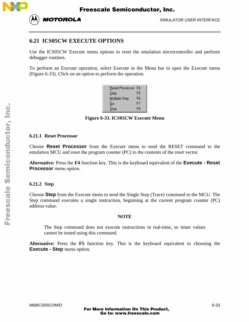
SIMULATOR USER INTERFACE
M68ICS05COM/D 6-33
6.21 ICS05CW EXECUTE OPTIONS
Use the ICS05CW Execute menu options to reset the emulation microcontroller and performdebugger routines.
To perform an Execute operation, select Execute in the Menu bar to open the Execute menu(Figure 6-33). Click on an option to perform the operation.
Figure 6-33. ICS05CW Execute Menu
6.21.1 Reset Processor
Choose Reset Processor from the Execute menu to send the RESET command to theemulation MCU and reset the program counter (PC) to the contents of the reset vector.
Alternative: Press the F4 function key. This is the keyboard equivalent of the Execute - ResetProcessor menu option.
6.21.2 Step
Choose Step from the Execute menu to send the Single Step (Trace) command to the MCU. TheStep command executes a single instruction, beginning at the current program counter (PC)address value.
NOTE
The Step command does not execute instructions in real-time, so timer valuescannot be tested using this command.
Alternative: Press the F5 function key. This is the keyboard equivalent to choosing theExecute - Step menu option.
Fre
esc
ale
Se
mic
on
du
cto
r, I
Freescale Semiconductor, Inc.
For More Information On This Product, Go to: www.freescale.com
nc
...
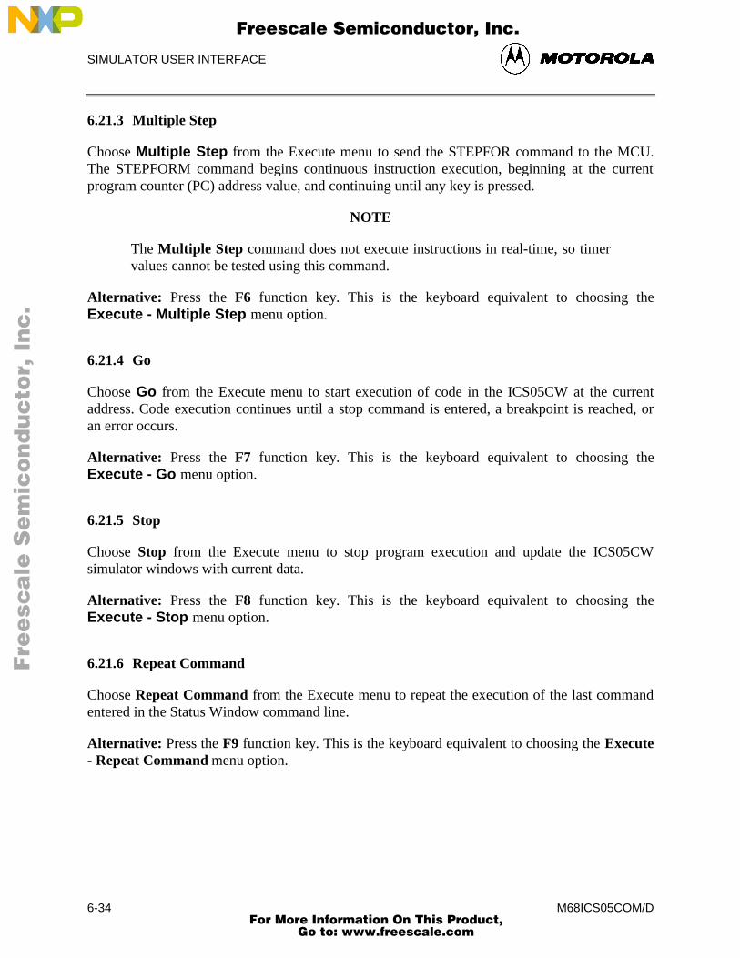
SIMULATOR USER INTERFACE
M68ICS05COM/D6-34
6.21.3 Multiple Step
Choose Multiple Step from the Execute menu to send the STEPFOR command to the MCU.The STEPFORM command begins continuous instruction execution, beginning at the currentprogram counter (PC) address value, and continuing until any key is pressed.
NOTE
The Multiple Step command does not execute instructions in real-time, so timervalues cannot be tested using this command.
Alternative: Press the F6 function key. This is the keyboard equivalent to choosing theExecute - Multiple Step menu option.
6.21.4 Go
Choose Go from the Execute menu to start execution of code in the ICS05CW at the currentaddress. Code execution continues until a stop command is entered, a breakpoint is reached, oran error occurs.
Alternative: Press the F7 function key. This is the keyboard equivalent to choosing theExecute - Go menu option.
6.21.5 Stop
Choose Stop from the Execute menu to stop program execution and update the ICS05CWsimulator windows with current data.
Alternative: Press the F8 function key. This is the keyboard equivalent to choosing theExecute - Stop menu option.
6.21.6 Repeat Command
Choose Repeat Command from the Execute menu to repeat the execution of the last commandentered in the Status Window command line.
Alternative: Press the F9 function key. This is the keyboard equivalent to choosing the Execute- Repeat Command menu option.
Fre
esc
ale
Se
mic
on
du
cto
r, I
Freescale Semiconductor, Inc.
For More Information On This Product, Go to: www.freescale.com
nc
...
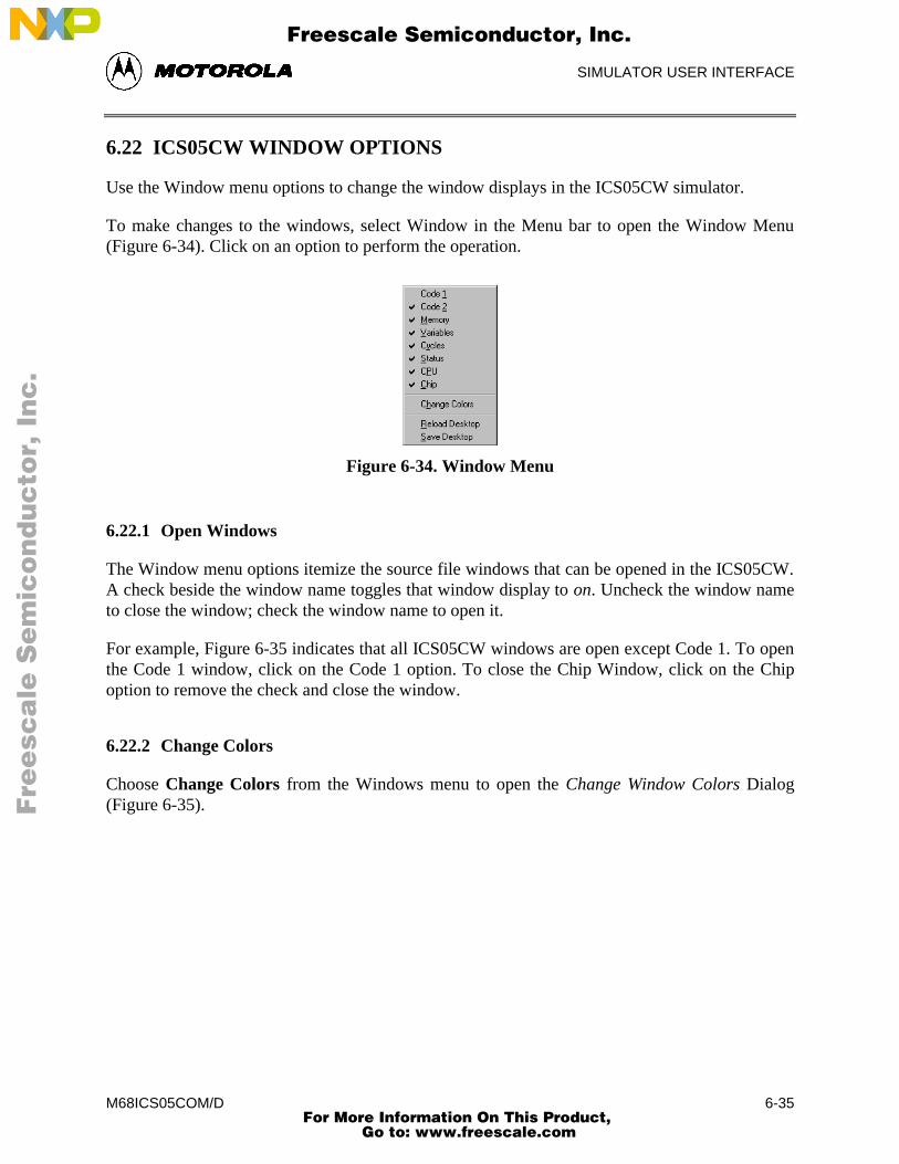
SIMULATOR USER INTERFACE
M68ICS05COM/D 6-35
6.22 ICS05CW WINDOW OPTIONS
Use the Window menu options to change the window displays in the ICS05CW simulator.
To make changes to the windows, select Window in the Menu bar to open the Window Menu(Figure 6-34). Click on an option to perform the operation.
Figure 6-34. Window Menu
6.22.1 Open Windows
The Window menu options itemize the source file windows that can be opened in the ICS05CW.A check beside the window name toggles that window display to on. Uncheck the window nameto close the window; check the window name to open it.
For example, Figure 6-35 indicates that all ICS05CW windows are open except Code 1. To openthe Code 1 window, click on the Code 1 option. To close the Chip Window, click on the Chipoption to remove the check and close the window.
6.22.2 Change Colors
Choose Change Colors from the Windows menu to open the Change Window Colors Dialog(Figure 6-35).
Fre
esc
ale
Se
mic
on
du
cto
r, I
Freescale Semiconductor, Inc.
For More Information On This Product, Go to: www.freescale.com
nc
...
SIMULATOR USER INTERFACE
M68ICS05COM/D6-36
The Change Window Colors dialog displays the color settings for the ICS05CW debuggerwindows or window components. To see the current settings, select the window or windowelement from the list on the left. To change the foreground or background color setting for thiswindow or element, uncheck the Use Defaults for Foreground/Background checkbox, and use theleft mouse button to select a foreground color, or use the right mouse button to select abackground color. Press the OK button to save the color changes (or press the Cancel button toclose the dialog without saving changes).
Some window items allow only the foreground or background to be changed.
Figure 6-35. Change Window Colors Dialog
6.22.3 Reload Desktop
Choose Reload Desktop from the Windows menu to reload the stored configuration for thecurrent project.
This option is useful for restoring desktop window to their stored sizes and locations aftermaking changes. To make changes permanent, choose the Save Desktop option. The newwindow sizes and locations will be written over the old settings, and stored with other projectfiles.
6.22.4 Save Desktop
Choose Save Desktop from the Windows menu to save the current configuration of thedesktop, the position and size of the windows in the ICS05CW simulator.
Fre
esc
ale
Se
mic
on
du
cto
r, I
Freescale Semiconductor, Inc.
For More Information On This Product, Go to: www.freescale.com
nc
...
DEBUGGING COMMAND SET
M68ICS05COM/D 7-1
CHAPTER 7
ICS05CW DEBUGGING COMMAND SET
7.1 OVERVIEW
This chapter consists of:
• A logical overview of the ICS05CW debugging command set
• An explanation of rules for using the command set, including command syntax andarguments
• A summary of commands by type and function
• Detailed descriptions of the commands, with example usage
The ICS05CW simulator command set consists of commands for simulating, debugging,analyzing, and programming microcontroller programs. Use the commands to:
• Initialize emulation memory
• Display and store data
• Debug user code
• Control the flow of code execution
Fre
esc
ale
Se
mic
on
du
cto
r, I
Freescale Semiconductor, Inc.
For More Information On This Product, Go to: www.freescale.com
nc
...
DEBUGGING COMMAND SET
M68ICS05COM/D7-2
7.2 ICS05CW COMMAND SYNTAX
A command is a line of ASCII text that you enter from the computer keyboard. For ICS05CWdebugging commands, enter the command and its arguments in the ICS05CW Status windowcommand line. Press Enter to terminate each line and activate the command. The typicalcommand syntax is:
command [<argument>]...
Where:
command A command name, in upper- or lower-case letters.
<argument> An argument indicator; when arguments are italicized, theyrepresent a placeholder for the actual value you enter; when notitalicized, they indicate the actual value to enter. Table 7-1 explainsthe possible argument values.
In command syntax descriptions:
[ ] brackets enclose optional items,
| a vertical line means or,
... an ellipsis means that you can repeat the preceding item,
( ) parentheses enclose items only for syntactical purposes
Except where otherwise noted, numerical values in debugging command examples arehexadecimal.
Fre
esc
ale
Se
mic
on
du
cto
r, I
Freescale Semiconductor, Inc.
For More Information On This Product, Go to: www.freescale.com
nc
...
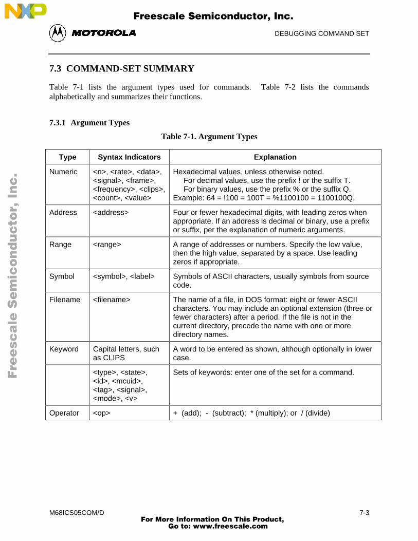
DEBUGGING COMMAND SET
M68ICS05COM/D 7-3
7.3 COMMAND-SET SUMMARY
Table 7-1 lists the argument types used for commands. Table 7-2 lists the commandsalphabetically and summarizes their functions.
7.3.1 Argument Types
Table 7-1. Argument Types
Type Syntax Indicators Explanation
Numeric <n>, <rate>, <data>,<signal>, <frame>,<frequency>, <clips>,<count>, <value>
Hexadecimal values, unless otherwise noted. For decimal values, use the prefix ! or the suffix T. For binary values, use the prefix % or the suffix Q.Example: 64 = !100 = 100T = %1100100 = 1100100Q.
Address <address> Four or fewer hexadecimal digits, with leading zeros whenappropriate. If an address is decimal or binary, use a prefixor suffix, per the explanation of numeric arguments.
Range <range> A range of addresses or numbers. Specify the low value,then the high value, separated by a space. Use leadingzeros if appropriate.
Symbol <symbol>, <label> Symbols of ASCII characters, usually symbols from sourcecode.
Filename <filename> The name of a file, in DOS format: eight or fewer ASCIIcharacters. You may include an optional extension (three orfewer characters) after a period. If the file is not in thecurrent directory, precede the name with one or moredirectory names.
Keyword Capital letters, suchas CLIPS
A word to be entered as shown, although optionally in lowercase.
<type>, <state>,<id>, <mcuid>,<tag>, <signal>,<mode>, <v>
Sets of keywords: enter one of the set for a command.
Operator <op> + (add); - (subtract); * (multiply); or / (divide)
Fre
esc
ale
Se
mic
on
du
cto
r, I
Freescale Semiconductor, Inc.
For More Information On This Product, Go to: www.freescale.com
nc
...
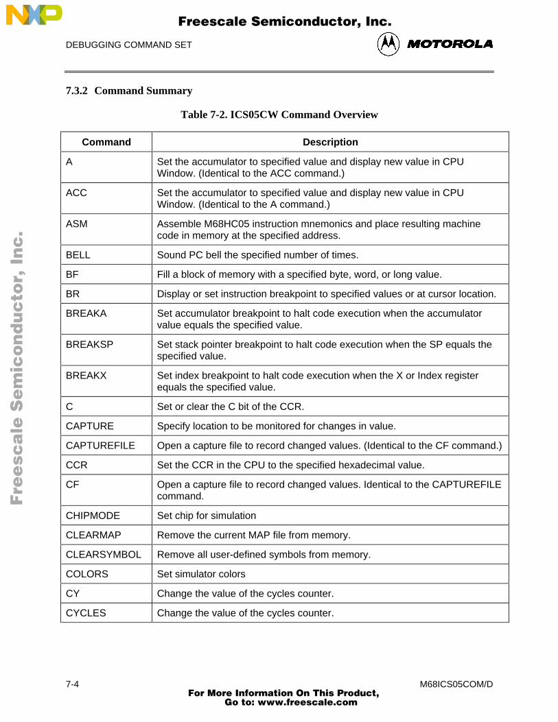
DEBUGGING COMMAND SET
M68ICS05COM/D7-4
7.3.2 Command Summary
Table 7-2. ICS05CW Command Overview
Command Description
A Set the accumulator to specified value and display new value in CPUWindow. (Identical to the ACC command.)
ACC Set the accumulator to specified value and display new value in CPUWindow. (Identical to the A command.)
ASM Assemble M68HC05 instruction mnemonics and place resulting machinecode in memory at the specified address.
BELL Sound PC bell the specified number of times.
BF Fill a block of memory with a specified byte, word, or long value.
BR Display or set instruction breakpoint to specified values or at cursor location.
BREAKA Set accumulator breakpoint to halt code execution when the accumulatorvalue equals the specified value.
BREAKSP Set stack pointer breakpoint to halt code execution when the SP equals thespecified value.
BREAKX Set index breakpoint to halt code execution when the X or Index registerequals the specified value.
C Set or clear the C bit of the CCR.
CAPTURE Specify location to be monitored for changes in value.
CAPTUREFILE Open a capture file to record changed values. (Identical to the CF command.)
CCR Set the CCR in the CPU to the specified hexadecimal value.
CF Open a capture file to record changed values. Identical to the CAPTUREFILEcommand.
CHIPMODE Set chip for simulation
CLEARMAP Remove the current MAP file from memory.
CLEARSYMBOL Remove all user-defined symbols from memory.
COLORS Set simulator colors
CY Change the value of the cycles counter.
CYCLES Change the value of the cycles counter.
Fre
esc
ale
Se
mic
on
du
cto
r, I
Freescale Semiconductor, Inc.
For More Information On This Product, Go to: www.freescale.com
nc
...
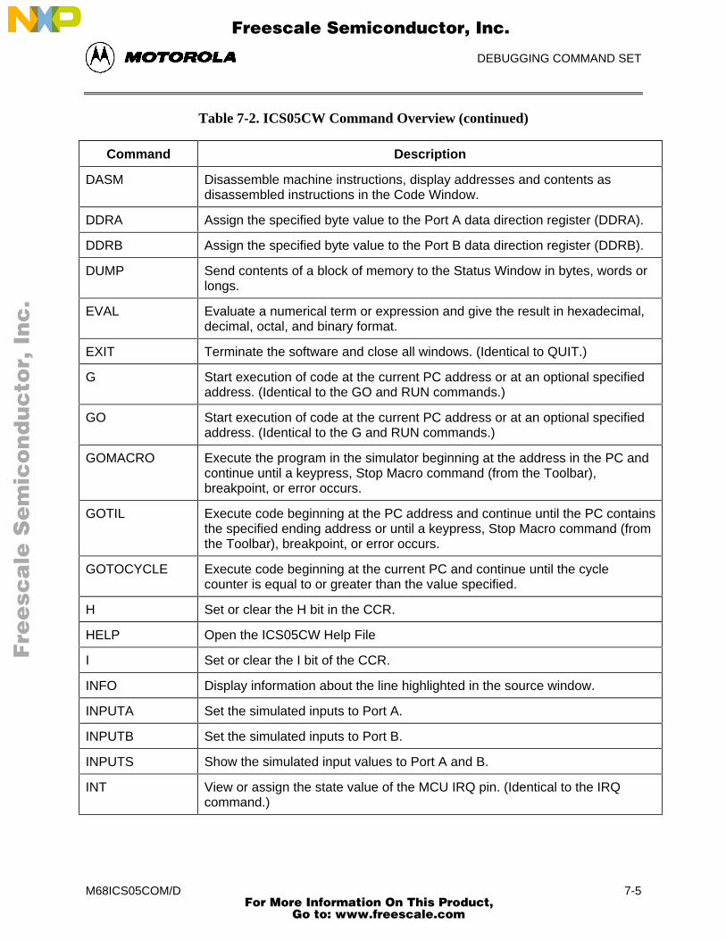
DEBUGGING COMMAND SET
M68ICS05COM/D 7-5
Table 7-2. ICS05CW Command Overview (continued)
Command Description
DASM Disassemble machine instructions, display addresses and contents asdisassembled instructions in the Code Window.
DDRA Assign the specified byte value to the Port A data direction register (DDRA).
DDRB Assign the specified byte value to the Port B data direction register (DDRB).
DUMP Send contents of a block of memory to the Status Window in bytes, words orlongs.
EVAL Evaluate a numerical term or expression and give the result in hexadecimal,decimal, octal, and binary format.
EXIT Terminate the software and close all windows. (Identical to QUIT.)
G Start execution of code at the current PC address or at an optional specifiedaddress. (Identical to the GO and RUN commands.)
GO Start execution of code at the current PC address or at an optional specifiedaddress. (Identical to the G and RUN commands.)
GOMACRO Execute the program in the simulator beginning at the address in the PC andcontinue until a keypress, Stop Macro command (from the Toolbar),breakpoint, or error occurs.
GOTIL Execute code beginning at the PC address and continue until the PC containsthe specified ending address or until a keypress, Stop Macro command (fromthe Toolbar), breakpoint, or error occurs.
GOTOCYCLE Execute code beginning at the current PC and continue until the cyclecounter is equal to or greater than the value specified.
H Set or clear the H bit in the CCR.
HELP Open the ICS05CW Help File
I Set or clear the I bit of the CCR.
INFO Display information about the line highlighted in the source window.
INPUTA Set the simulated inputs to Port A.
INPUTB Set the simulated inputs to Port B.
INPUTS Show the simulated input values to Port A and B.
INT View or assign the state value of the MCU IRQ pin. (Identical to the IRQcommand.)
Fre
esc
ale
Se
mic
on
du
cto
r, I
Freescale Semiconductor, Inc.
For More Information On This Product, Go to: www.freescale.com
nc
...
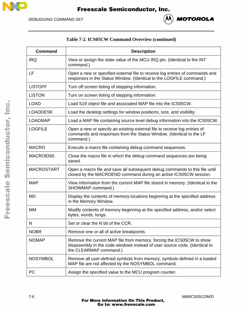
DEBUGGING COMMAND SET
M68ICS05COM/D7-6
Table 7-2. ICS05CW Command Overview (continued)
Command Description
IRQ View or assign the state value of the MCU IRQ pin. (Identical to the INTcommand.)
LF Open a new or specified external file to receive log entries of commands andresponses in the Status Window. (Identical to the LOGFILE command.)
LISTOFF Turn off screen listing of stepping information.
LISTON Turn on screen listing of stepping information.
LOAD Load S19 object file and associated MAP file into the ICS05CW.
LOADDESK Load the desktop settings for window positions, size, and visibility.
LOADMAP Load a MAP file containing source level debug information into the ICS05CW.
LOGFILE Open a new or specify an existing external file to receive log entries ofcommands and responses from the Status Window. (Identical to the LFcommand.)
MACRO Execute a macro file containing debug command sequences.
MACROEND Close the macro file in which the debug command sequences are beingsaved.
MACROSTART Open a macro file and save all subsequent debug commands to this file untilclosed by the MACROEND command during an active ICS05CW session.
MAP View information from the current MAP file stored in memory. (Identical to theSHOWMAP command.)
MD Display the contents of memory locations beginning at the specified addressin the Memory Window.
MM Modify contents of memory beginning at the specified address, and/or selectbytes, words, longs.
N Set or clear the N bit of the CCR.
NOBR Remove one or all of active breakpoints.
NOMAP Remove the current MAP file from memory, forcing the ICS05CW to showdisassembly in the code windows instead of user source code. (Identical tothe CLEARMAP command.)
NOSYMBOL Remove all user-defined symbols from memory; symbols defined in a loadedMAP file are not affected by the NOSYMBOL command.
PC Assign the specified value to the MCU program counter.
Fre
esc
ale
Se
mic
on
du
cto
r, I
Freescale Semiconductor, Inc.
For More Information On This Product, Go to: www.freescale.com
nc
...
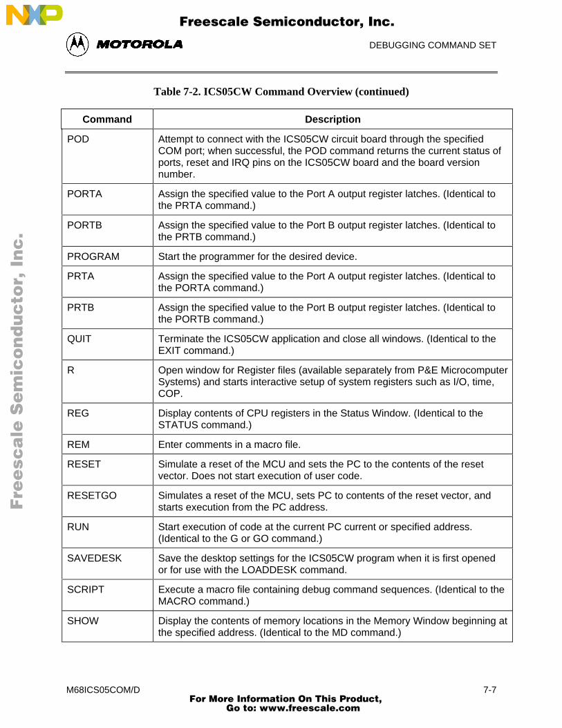
DEBUGGING COMMAND SET
M68ICS05COM/D 7-7
Table 7-2. ICS05CW Command Overview (continued)
Command Description
POD Attempt to connect with the ICS05CW circuit board through the specifiedCOM port; when successful, the POD command returns the current status ofports, reset and IRQ pins on the ICS05CW board and the board versionnumber.
PORTA Assign the specified value to the Port A output register latches. (Identical tothe PRTA command.)
PORTB Assign the specified value to the Port B output register latches. (Identical tothe PRTB command.)
PROGRAM Start the programmer for the desired device.
PRTA Assign the specified value to the Port A output register latches. (Identical tothe PORTA command.)
PRTB Assign the specified value to the Port B output register latches. (Identical tothe PORTB command.)
QUIT Terminate the ICS05CW application and close all windows. (Identical to theEXIT command.)
R Open window for Register files (available separately from P&E MicrocomputerSystems) and starts interactive setup of system registers such as I/O, time,COP.
REG Display contents of CPU registers in the Status Window. (Identical to theSTATUS command.)
REM Enter comments in a macro file.
RESET Simulate a reset of the MCU and sets the PC to the contents of the resetvector. Does not start execution of user code.
RESETGO Simulates a reset of the MCU, sets PC to contents of the reset vector, andstarts execution from the PC address.
RUN Start execution of code at the current PC current or specified address.(Identical to the G or GO command.)
SAVEDESK Save the desktop settings for the ICS05CW program when it is first openedor for use with the LOADDESK command.
SCRIPT Execute a macro file containing debug command sequences. (Identical to theMACRO command.)
SHOW Display the contents of memory locations in the Memory Window beginning atthe specified address. (Identical to the MD command.)
Fre
esc
ale
Se
mic
on
du
cto
r, I
Freescale Semiconductor, Inc.
For More Information On This Product, Go to: www.freescale.com
nc
...
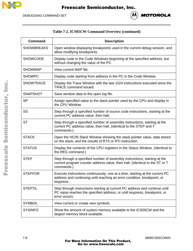
DEBUGGING COMMAND SET
M68ICS05COM/D7-8
Table 7-2. ICS05CW Command Overview (continued)
Command Description
SHOWBREAKS Open window displaying breakpoints used in the current debug session, andallow modifying breakpoints.
SHOWCODE Display code in the Code Windows beginning at the specified address, butwithout changing the value of the PC.
SHOWMAP View current MAP file.
SHOWPC Display code starting from address in the PC in the Code Window.
SHOWTRACE Display the Trace Window with the last 1024 instructions executed since theTRACE command issued.
SNAPSHOT Save window data to the open log file.
SP Assign specified value to the stack pointer used by the CPU and display inthe CPU Window.
SS Step through a specified number of source code instructions, starting at thecurrent PC address value, then halt.
ST Step through a specified number of assembly instructions, starting at thecurrent PC address value, then halt. (Identical to the STEP and Tcommands.)
STACK Open the HC05 Stack Window showing the stack pointer value, data storedon the stack, and the results of RTS or RTI instruction.
STATUS Display the contents of the CPU registers in the Status Window. (Identical tothe REG command.)
STEP Step through a specified number of assembly instructions, starting at thecurrent program counter address value, then halt. (Identical to the ST or Tcommands.)
STEPFOR Execute instructions continuously, one at a time, starting at the current PCaddress and continuing until reaching an error condition, breakpoint, orkeypress.
STEPTIL Step through instructions starting at current PC address and continue untilPC value reaches the specified address, or until keypress, breakpoint, orerror occurs.
SYMBOL View current or create new symbols.
SYSINFO Show the amount of system memory available to the ICS05CW and thelargest memory block available.
Fre
esc
ale
Se
mic
on
du
cto
r, I
Freescale Semiconductor, Inc.
For More Information On This Product, Go to: www.freescale.com
nc
...
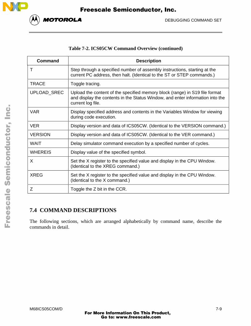
DEBUGGING COMMAND SET
M68ICS05COM/D 7-9
Table 7-2. ICS05CW Command Overview (continued)
Command Description
T Step through a specified number of assembly instructions, starting at thecurrent PC address, then halt. (Identical to the ST or STEP commands.)
TRACE Toggle tracing.
UPLOAD_SREC Upload the content of the specified memory block (range) in S19 file formatand display the contents in the Status Window, and enter information into thecurrent log file.
VAR Display specified address and contents in the Variables Window for viewingduring code execution.
VER Display version and data of ICS05CW. (Identical to the VERSION command.)
VERSION Display version and data of ICS05CW. (Identical to the VER command.)
WAIT Delay simulator command execution by a specified number of cycles.
WHEREIS Display value of the specified symbol.
X Set the X register to the specified value and display in the CPU Window.(Identical to the XREG command.)
XREG Set the X register to the specified value and display in the CPU Window.(Identical to the X command.)
Z Toggle the Z bit in the CCR.
7.4 COMMAND DESCRIPTIONS
The following sections, which are arranged alphabetically by command name, describe thecommands in detail.
Fre
esc
ale
Se
mic
on
du
cto
r, I
Freescale Semiconductor, Inc.
For More Information On This Product, Go to: www.freescale.com
nc
...

DEBUGGING COMMAND SET
M68ICS05COM/D7-10
A or ACC Set Accumulator Value
The ACC command sets the accumulator to a specified value. The value entered with thecommand is shown in the CPU window. The ACC and A commands are identical.
Syntax:
ACC <n>
where:
<n> The value to be loaded into the accumulator.
Example:
A 10 Set the accumulator to $10.
Fre
esc
ale
Se
mic
on
du
cto
r, I
Freescale Semiconductor, Inc.
For More Information On This Product, Go to: www.freescale.com
nc
...
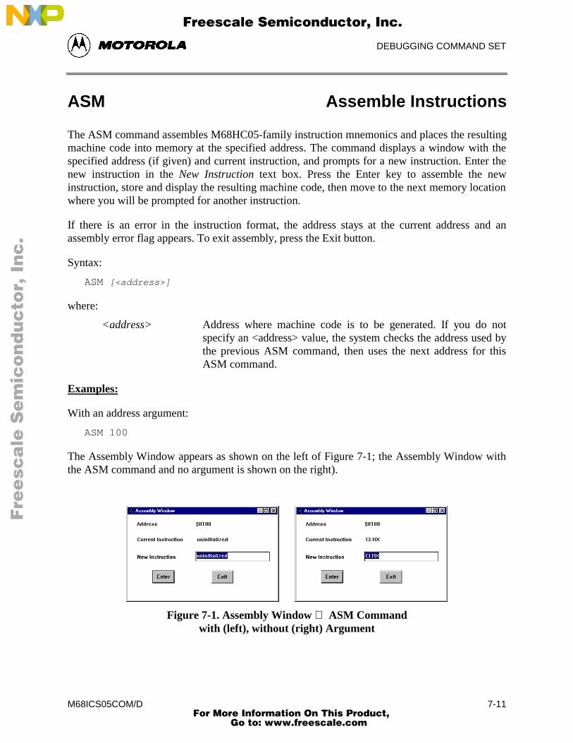
DEBUGGING COMMAND SET
M68ICS05COM/D 7-11
ASM Assemble Instructions
The ASM command assembles M68HC05-family instruction mnemonics and places the resultingmachine code into memory at the specified address. The command displays a window with thespecified address (if given) and current instruction, and prompts for a new instruction. Enter thenew instruction in the New Instruction text box. Press the Enter key to assemble the newinstruction, store and display the resulting machine code, then move to the next memory locationwhere you will be prompted for another instruction.
If there is an error in the instruction format, the address stays at the current address and anassembly error flag appears. To exit assembly, press the Exit button.
Syntax:
ASM [<address>]
where:
<address> Address where machine code is to be generated. If you do notspecify an <address> value, the system checks the address used bythe previous ASM command, then uses the next address for thisASM command.
Examples:
With an address argument:
ASM 100
The Assembly Window appears as shown on the left of Figure 7-1; the Assembly Window withthe ASM command and no argument is shown on the right).
Figure 7-1. Assembly Window ASM Commandwith (left), without (right) Argument
Fre
esc
ale
Se
mic
on
du
cto
r, I
Freescale Semiconductor, Inc.
For More Information On This Product, Go to: www.freescale.com
nc
...
DEBUGGING COMMAND SET
M68ICS05COM/D7-12
BELL Sound PC Bell
The BELL command sounds the PC bell the specified number of times. If you enter no argument,the bell sounds once. To turn off the bell as it is sounding, press any key.
Syntax:
BELL [<n>]
where:
<n> The number of times to sound the bell.
Example:
BELL 3 Ring PC bell 3 times.
Fre
esc
ale
Se
mic
on
du
cto
r, I
Freescale Semiconductor, Inc.
For More Information On This Product, Go to: www.freescale.com
nc
...
DEBUGGING COMMAND SET
M68ICS05COM/D 7-13
BF Block Fill Memory
The BF command fills a block of memory with a specified byte, word, or long value. Theoptional argument specifies whether to fill the block in bytes (.B, the default, 8 bits), in words(.W, 16 bits), or in longs (.L, 32 bits).
Syntax:
BF [.B | .W | .L] <startrange> <endrange> <n>
where:
<startrange> Beginning address of the memory block (range).
<endrange> Ending address of the memory block (range).
<n> Byte, word, or long value to be stored in the specified block.
• If the byte variant (.B) is used , then <n> must be a 8-bit value.
• If the word variant (.W) is used , then <n> must be a 16-bit value.
• If the long variant (.L) is used , then <n> must be a 32-bit value.
Examples:
BF C0 CF FF Store FF in bytes at addresses C0-CF.
BF.W 300 31F 4143 Store word value 4143 at addresses 300-31F.
Fre
esc
ale
Se
mic
on
du
cto
r, I
Freescale Semiconductor, Inc.
For More Information On This Product, Go to: www.freescale.com
nc
...
DEBUGGING COMMAND SET
M68ICS05COM/D7-14
BR Set Instruction Breakpoint
The BR command displays or sets instruction breakpoints, according to its parameter values:
• If you enter no parameter values, the BR command displays a list of all currentbreakpoints in the status window.
• If you enter an <address> value, the BR command sets a breakpoint at the specifiedaddress.
You may also enter an optional value <n> with the address to specify a break count. The BRcommand sets a breakpoint at the specified address, but code execution does not break until thenth time it arrives at the breakpoint.
NOTE
The maximum number of breakpoint addresses is 64. Each BR,BREAKA, BREAKSP, or BREAKX command that includes anaddress value uses an additional breakpoint address, unless theaddress is a duplicate. For example, if 64 BR commands alreadyhave taken up 64 addresses, the only way to include an addressvalue in a BREAKA, BREAKSP, or BREAKX command is toduplicate one of those 64 addresses.
If source code is displayed in either code window, you can set, remove, or clear all breakpointsusing mouse or keyboard commands:
1. Position the cursor on the line of code for which you want to set a breakpoint.
2. Press the right mouse button once to open the Code Window Shortcut Menu.
3. Select Toggle Breakpoint at Cursor option. If there is no current breakpoint set at thisline of code, a breakpoint will be set. If there is a current breakpoint set at this line ofcode, the breakpoint will be removed.
To remove all breakpoints:
• Enter the NOBR command in the Status Window command line.
Fre
esc
ale
Se
mic
on
du
cto
r, I
Freescale Semiconductor, Inc.
For More Information On This Product, Go to: www.freescale.com
nc
...
DEBUGGING COMMAND SET
M68ICS05COM/D 7-15
BR (continued)
Syntax:
BR [<address> [<n>]] ;set a breakpoint
BR ;list current breakpoints
where:
<address> The address for a breakpoint.
<n> Break after value: code execution passes through the breakpoint n-1 times, then breaks the nth time it arrives at the breakpoint.
Examples:
BR 300 Set a breakpoint at address 300
BR 330 8 Set a breakpoint at address 330, break on eighth arrival at330.
Fre
esc
ale
Se
mic
on
du
cto
r, I
Freescale Semiconductor, Inc.
For More Information On This Product, Go to: www.freescale.com
nc
...
DEBUGGING COMMAND SET
M68ICS05COM/D7-16
BREAKA Set Accumulator Breakpoint
The BREAKA command sets an accumulator breakpoint to halt code execution when the valueof the accumulator equals the specified n value.
• With an n value, the command forces a break in execution as soon as the accumulatorvalue equals n.
• With n and address values, the command forces a break in execution when theaccumulator value equals n and execution arrives at the specified address. (If theaccumulator value changes from n by the time execution arrives at the address, nobreak occurs).
NOTE
The maximum number of breakpoint addresses is 64. Each BR,BREAKA, BREAKSP, or BREAKX command that includes anaddress value uses an additional breakpoint address, unless theaddress is a duplicate. For example, if 64 BR commands alreadyhave taken up 64 addresses, the only way to include an addressvalue in a BREAKA, BREAKSP, or BREAKX command is toduplicate one of those 64 addresses.
If you enter the BREAKA command without an address value, the halt in code execution clearsthe accumulator breakpoint. To cancel the accumulator breakpoint before the halt occurs, enterthe BREAKA command without any parameter values. (If you enter the BREAKA commandwithout an address value, the accumulator breakpoint does not show in the BREAKPOINTWINDOW.)
If you enter the BREAKA command with an address value, you may clear the accumulatorbreakpoint by one of these methods:
• Enter the NOBR command
• Position the cursor on that address in the code window, then press the right mousebutton, and select Toggle Breakpoint at Cursor menu item.
Syntax:
BREAKA [<n> [<address>]]
where:
<n> Accumulator value that triggers a break in execution.
<address> Optional address for the break in execution (provided that theaccumulator value equals n).
Fre
esc
ale
Se
mic
on
du
cto
r, I
Freescale Semiconductor, Inc.
For More Information On This Product, Go to: www.freescale.com
nc
...
DEBUGGING COMMAND SET
M68ICS05COM/D 7-17
BREAKA (continued)
Examples:
BREAKA 55 Break execution when the accumulator value equals 55.
BREAKA Cancel the accumulator breakpoint.
BREAKA 55 300 Break execution at address 300 if accumulator value equals55.
Fre
esc
ale
Se
mic
on
du
cto
r, I
Freescale Semiconductor, Inc.
For More Information On This Product, Go to: www.freescale.com
nc
...
DEBUGGING COMMAND SET
M68ICS05COM/D7-18
BREAKSP Set Stack Pointer Breakpoint
The BREAKSP command sets a stack pointer breakpoint to halt code execution when the valueof the stack pointer equals a specified value.
• With an n value, the command forces a break in execution as soon as the stack pointervalue equals n.
• With n and address values, the BREAKSP command forces a halt in execution whenthe stack pointer value equals n and execution arrives at the specified address. (If thestack pointer value changes from n by the time execution arrives at the address, nobreak occurs).
NOTE
The maximum number of breakpoint addresses is 64. Each BR,BREAKA, BREAKSP, or BREAKX command that includes anaddress value uses an additional breakpoint address, unless theaddress is a duplicate. For example, if 64 BR commands alreadyhave taken up 64 addresses, the only way to include an addressvalue in a BREAKA, BREAKSP or BREAKX command is toduplicate one of those 64 addresses.
If you enter the BREAKSP command without an address value, the halt in code execution clearsthe stack pointer breakpoint. To cancel the stack pointer breakpoint before the halt occurs, enterthe BREAKSP command without any parameter values. (If you enter the BREAKSP commandwithout an address value, the stack pointer breakpoint does not show in the BreakpointWindow.)
If you enter the BREAKSP command with an address value, you may clear the stack pointerbreakpoint by one of these methods:
• Enter the NOBR command
• Position the cursor on that address in the code window, then press the right mousebutton, and select Toggle Breakpoint at Cursor menu item.
Fre
esc
ale
Se
mic
on
du
cto
r, I
Freescale Semiconductor, Inc.
For More Information On This Product, Go to: www.freescale.com
nc
...
DEBUGGING COMMAND SET
M68ICS05COM/D 7-19
BREAKSP (continued)
Syntax:
BREAKSP [<n> [<address>]]
where:
<n> Stack pointer value that triggers a break in execution.
<address> Optional address for the break in execution (when that the stackpointer value equals n).
Examples:
BREAKSP E0 Break execution when the stack pointer (SP) value equalsE0.
BREAKSP Cancel the SP breakpoint.
BREAKSP E0 300 Break execution at address 300 if SP value equals E0.
Fre
esc
ale
Se
mic
on
du
cto
r, I
Freescale Semiconductor, Inc.
For More Information On This Product, Go to: www.freescale.com
nc
...

DEBUGGING COMMAND SET
M68ICS05COM/D7-20
BREAKX Set Index Register Breakpoint
The BREAKX command sets an index breakpoint to halt code execution when the value of theindex register equals the specified n value.
• With an n value, the command forces a break in execution as soon as the indexregister value equals n.
• With n and address values, the command forces a halt in execution when the indexregister value equals n and execution arrives at the specified address. (If the indexregister value changes from n by the time execution arrives at the address, no haltoccurs).
NOTE
The maximum number of breakpoint addresses is 64. Each BR,BREAKA, BREAKSP, or BREAKX command that includes anaddress value uses an additional breakpoint address, unless theaddress is a duplicate. For example, if 64 BR commands alreadyhave taken up 64 addresses, the only way to include an addressvalue in a BREAKA, BREAKSP or BREAKX command is toduplicate one of those 64 addresses.
If you enter the BREAKX command without an address value, the halt in code execution clearsthe index register breakpoint. To cancel the index register breakpoint before the halt occurs, enterthe BREAKX command without any parameter values. (If you enter the BREAKX commandwithout an address value, the index register breakpoint does not show in the BreakpointWindow.)
If you enter the BREAKX command with an address value, you may clear the index registerbreakpoint using one of these methods:
• Enter the NOBR command
• Position the cursor on that address in the code window, then press the right mousebutton, and select Toggle Breakpoint at Cursor menu item.
Syntax:
BREAKX [<n> [<address>]]
where:
<n> Index register value that triggers a break in execution.
<address> Optional address for the break in execution (when that the indexregister value equals n).
Fre
esc
ale
Se
mic
on
du
cto
r, I
Freescale Semiconductor, Inc.
For More Information On This Product, Go to: www.freescale.com
nc
...

DEBUGGING COMMAND SET
M68ICS05COM/D 7-21
BREAKX (continued)
Examples:
BREAKX A9 Break execution when the index register value equals A9.
BREAKX Cancel the index breakpoint.
BREAKX A9 300 Break execution at address 300 if index register valueequals A9.
Fre
esc
ale
Se
mic
on
du
cto
r, I
Freescale Semiconductor, Inc.
For More Information On This Product, Go to: www.freescale.com
nc
...
DEBUGGING COMMAND SET
M68ICS05COM/D7-22
C Set/Clear Carry Bit
The C command sets or clears the C bit of the condition code register (CCR).
NOTE
The CCR bit designators are in the lower portion of the CPUwindow. The CCR pattern is 111HINZC (H is half-carry, I is IRQinterrupt mask, N is negative, Z is zero and C is carry). A letter inthese designators means that the corresponding bit of the CCR isset; a period means that the corresponding bit is clear.
Syntax:
C 0|1
Examples:
C 0 Clears the C bit of the CCR.
C 1 Sets the C bit of the CCR.
Fre
esc
ale
Se
mic
on
du
cto
r, I
Freescale Semiconductor, Inc.
For More Information On This Product, Go to: www.freescale.com
nc
...
DEBUGGING COMMAND SET
M68ICS05COM/D 7-23
CAPTURE Capture Changed Data
The CAPTURE command specifies locations to be monitored for changes in value. If the valueof such a location changes and if a capture file is open, the file records the change in value. (Seethe CAPTUREFILE or CF command for more information about capture files).
To stop monitoring a location, specify that same location in another CAPTURE command, orclose the capture file. (Closing the capture file undoes the specifications for all monitoringlocations).
NOTE
Before you enter the CAPTURE command, open a capture file viathe CAPTUREFILE or CF command. The CAPTURE commandhas no effect unless a capture file is open.
Syntax:
CAPTURE <address> [<address>...]
where:
<address> Location to be monitored for a change in value.
Examples:
CAPTURE PORTA Monitor location PORTA for any value changes.
CAPTURE C0 Monitor RAM location C0 for any value changes.
CAPTURE D0 D1 D2 Monitor for any value changes in an array of locations.
Fre
esc
ale
Se
mic
on
du
cto
r, I
Freescale Semiconductor, Inc.
For More Information On This Product, Go to: www.freescale.com
nc
...
DEBUGGING COMMAND SET
M68ICS05COM/D7-24
CAPTUREFILE or CF Open/Close Capture File
The CAPTUREFILE command opens a capture file to record changed values. If the specified filedoes not yet exist, this command creates the file. If the file already exists, you can use an optionalparameter to specify whether to overwrite existing contents (R, the default) or to append the logentries (A). If you omit this parameter, a prompt asks for this overwrite/append choice.
The command interpreter does not assume a filename extension for the capture file. To close thecapture file, enter this command without any parameter values.
The CF and CAPTUREFILE commands are identical. If no CAPTURE command has specifiedlocations to be monitored, the CF and CAPTUREFILE commands have no effect.
NOTES
The CAPTURE command specifies the location to be monitoredfor value changes. Closing the capture file deletes the locationspecification. The simulator continues writing to an open capturefile. The capture file must be closed within a reasonable time, toprevent the file from growing large.
Syntax:
CAPTUREFILE [<filename> [R | A]]
where:
<filename> Name of the capture file.
Examples:
CAPTUREFILE TEST.CAP Open capture file TEST.CAP
CF TEST4.CAP A Open capture file TEST4.CAP; append new entries
Fre
esc
ale
Se
mic
on
du
cto
r, I
Freescale Semiconductor, Inc.
For More Information On This Product, Go to: www.freescale.com
nc
...
DEBUGGING COMMAND SET
M68ICS05COM/D 7-25
CCR Set Condition Code Register
The CCR command sets the condition code register (CCR in the CPU) to the specifiedhexadecimal value. The value entered with the command displays in the CPU Window.
NOTE
The CCR bit designators are in the lower portion of the CPUwindow. The CCR binary pattern is 111HINZC (H is half-carry, Iis IRQ interrupt mask, N is negative, Z is zero and C is carry). Aletter in these designators means that the corresponding bit is set; aperiod means that the corresponding bit is clear.
Syntax:
CCR <n>
where:
<n> The new hexadecimal value for the CCR.
Example:
CCR E4 Assign the value E4 to the CCR. This makes the binarypattern 11100100; the N bit set, other bits clear.
Fre
esc
ale
Se
mic
on
du
cto
r, I
Freescale Semiconductor, Inc.
For More Information On This Product, Go to: www.freescale.com
nc
...
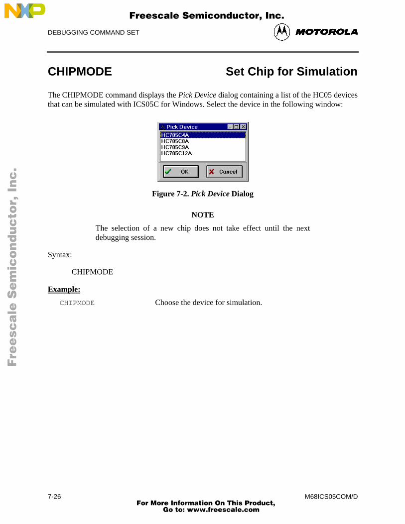
DEBUGGING COMMAND SET
M68ICS05COM/D7-26
CHIPMODE Set Chip for Simulation
The CHIPMODE command displays the Pick Device dialog containing a list of the HC05 devicesthat can be simulated with ICS05C for Windows. Select the device in the following window:
Figure 7-2. Pick Device Dialog
NOTE
The selection of a new chip does not take effect until the nextdebugging session.
Syntax:
CHIPMODE
Example:
CHIPMODE Choose the device for simulation.
Fre
esc
ale
Se
mic
on
du
cto
r, I
Freescale Semiconductor, Inc.
For More Information On This Product, Go to: www.freescale.com
nc
...
DEBUGGING COMMAND SET
M68ICS05COM/D 7-27
CLEARMAP Clear .MAP File
The CLEARMAP command removes the current MAP file from memory, forcing the debuggerto show disassembled code in the Code Windows instead of source code. Symbols defined usingthe SYMBOL command are not affected by this command. (The NOMAP command is identicalto CLEARMAP.)
Syntax:
CLEARMAP
Example:
CLEARMAP Clears symbols and their definitions.
Fre
esc
ale
Se
mic
on
du
cto
r, I
Freescale Semiconductor, Inc.
For More Information On This Product, Go to: www.freescale.com
nc
...
DEBUGGING COMMAND SET
M68ICS05COM/D7-28
CLEARSYMBOL Clear User Symbols
The CLEARSYMBOL command removes all the user-defined symbols (created with theSYMBOL command). Debug information from MAP files, used for source level debugging, isnot affected by the CLEARSYMBOL command.
NOTE
List the current user-defined symbols using the SYMBOLcommand.
Syntax:
CLEARSYMBOL
Example:
CLEARSYMBOL Clears user defined symbols.
Fre
esc
ale
Se
mic
on
du
cto
r, I
Freescale Semiconductor, Inc.
For More Information On This Product, Go to: www.freescale.com
nc
...
DEBUGGING COMMAND SET
M68ICS05COM/D 7-29
COLORS Set Simulator Colors
The COLORS command opens the Change Window Colors dialog that lets you choose the textand background colors for windows in the ICS05CW simulator. After you set colors options forthe windows, save the changes using the SAVEDESK command. For more information aboutusing the Change Window Colors dialog, see paragraph 6.22.2.
Syntax:
COLORS
Example:
COLORS Open the colors window.
Fre
esc
ale
Se
mic
on
du
cto
r, I
Freescale Semiconductor, Inc.
For More Information On This Product, Go to: www.freescale.com
nc
...
DEBUGGING COMMAND SET
M68ICS05COM/D7-30
CYCLES Set Cycles Counter
The CYCLES command changes the value of the cycle counter. The cycle counter counts thenumber of processor cycles that have passed during execution. The Cycle Window shows thecycle counter. The cycle count can be useful for timing procedures.
Syntax:
CYCLES <n>
where:
<n> Integer value for the cycles counter.
Examples:
CYCLES 0 Reset cycles counter.
CY 1000 Set cycle-counter value to 1000.
Fre
esc
ale
Se
mic
on
du
cto
r, I
Freescale Semiconductor, Inc.
For More Information On This Product, Go to: www.freescale.com
nc
...
DEBUGGING COMMAND SET
M68ICS05COM/D 7-31
DASM Disassemble Memory
The DASM command disassembles machine instructions, displaying the addresses and theircontents as disassembled instructions in the debug window.
• If the command includes an address value, one disassembled instruction is shown,beginning at that address.
• If you enter the command without any parameter values, the software finds the mostrecently disassembled instruction then shows the next instruction, disassembled.
• If the command includes startrange and endrange values, the software showsdisassembled instructions for the range.
NOTE
If you enter the DASM command with a range, sometimes thedisassembled instructions scroll through the status window toorapidly to view. In this case, enter the LF command, to record thedisassembled instructions in a logfile, or use the scroll bars in thestatus window.
Syntax:
DASM [<address> | <startrange> <endrange>]
where:
<address> First address of three instruction opcodes to be disassembled.
<startrange> Starting address for a range of instructions to be disassembled.
<endrange> Ending address for a range of instructions to be disassembled.
Examples:
DASM 3000300 A6E8 LDA #0E8DASM 200 2080200 5F CLRX0201 A680 LDA #800203 B700 STA PORTA0205 A6FE LDA #FE0207 B704 STA DDRA
Fre
esc
ale
Se
mic
on
du
cto
r, I
Freescale Semiconductor, Inc.
For More Information On This Product, Go to: www.freescale.com
nc
...
DEBUGGING COMMAND SET
M68ICS05COM/D7-32
DDRA Set Port A Direction Register
The DDRA command assigns the specified byte value to the port A data direction register(DDRA). Bits assigned 0 denote input pins; bits assigned 1 denote output pins.
Syntax:
DDRA <n>
where:
<n> The byte value to be placed into DDRA.
Examples:
DDRA FF Set all port A pins to be outputs.
DDRA 00 Set all port A pins to be inputs.
Fre
esc
ale
Se
mic
on
du
cto
r, I
Freescale Semiconductor, Inc.
For More Information On This Product, Go to: www.freescale.com
nc
...
DEBUGGING COMMAND SET
M68ICS05COM/D 7-33
DDRB Set Port B Direction Register
The DDRB command assigns the specified byte value to the port B data direction register(DDRB). Bits assigned 0 denote input pins; bits assigned 1 denote output pins.
Syntax:
DDRB <n>
where:
<n> The byte value to be placed into DDRB.
Examples:
DDRB 03 Set the lower two bits of port B pins as outputs, set theothers to be inputs.
DDRB FF Set all port B pins to be outputs.
Fre
esc
ale
Se
mic
on
du
cto
r, I
Freescale Semiconductor, Inc.
For More Information On This Product, Go to: www.freescale.com
nc
...
DEBUGGING COMMAND SET
M68ICS05COM/D7-34
DUMP Dump Memory to Screen
The DUMP command sends contents of a block of memory to the status window, in bytes,words, or longs. The optional variant specifies whether to fill the block in bytes (.B, the default),in words (.W), or in longs (.L).
NOTE
When you enter the DUMP command, sometimes the memorycontents scroll through the debug window too rapidly to view.Accordingly, you can either the LF command to record the memorylocations in a logfile, or use the scroll bars in the status window.
Syntax:
DUMP [.B | .W | .L] <startrange> <endrange> [<n>]
where:
<startrange> Beginning address of the memory block.
<endrange> Ending address of the memory block (range).
<n> Optional number of bytes, words, or longs to be written on oneline.
Examples:
DUMP C0 CF Dump array of RAM values, in bytes.DUMP.W 300 37S Dump ROM code in address 300-37S in words.DUMP.B 200 300 Dump contents of addresses 200-300 in rows of eight bytes.
Fre
esc
ale
Se
mic
on
du
cto
r, I
Freescale Semiconductor, Inc.
For More Information On This Product, Go to: www.freescale.com
nc
...
DEBUGGING COMMAND SET
M68ICS05COM/D 7-35
EVAL Evaluate Expression
The EVAL command evaluates a numerical term or simple expression, giving the result inhexadecimal, decimal, octal, and binary formats. In an expression, spaces must separate theoperator from the numerical terms.
NOTE
Octal numbers are not valid as parameter values. Operand valuesmust be 16 bits or less. If the value is an ASCII character, thiscommand also shows the ASCII character as well. The parametersfor the command can be a number, or a sequence of: number,space, operator, space, and number. Supported operations areaddition (+), subtraction (-), multiplication (*), division (/), logicalAND (&), and logical OR (^).
Syntax:
EVAL <n> [<op> <n>]
where:
<n> Alone, the numerical term to be evaluated. Otherwise eithernumerical term of a simple expression.
<op> The arithmetic operator (+, -, *, /, &, or ^) of a simple expressionto be evaluated.
Examples:
EVAL 45 + 32
0077H 119T 0001670 0000000001110111Q "w"
EVAL 100T
0064H 100T 0001440 0000000001100100Q "d"
Fre
esc
ale
Se
mic
on
du
cto
r, I
Freescale Semiconductor, Inc.
For More Information On This Product, Go to: www.freescale.com
nc
...
DEBUGGING COMMAND SET
M68ICS05COM/D7-36
EXIT or QUIT Exit/Quit Application
The EXIT command terminates the software and closes all windows. The QUIT command isidentical to EXIT.
Syntax:
EXIT
Example:
EXIT Finish working with the program.
Fre
esc
ale
Se
mic
on
du
cto
r, I
Freescale Semiconductor, Inc.
For More Information On This Product, Go to: www.freescale.com
nc
...
DEBUGGING COMMAND SET
M68ICS05COM/D 7-37
GO Begin Program Execution
The GO command starts execution of code at the current program counter (PC) address, or at anoptional specified address.
The G, GO, and RUN commands are identical.
If you enter only one address, that address is the starting address. If you enter a second address,the execution stops at that address. If you specify only one address, the execution continues untilyou press a key, it arrives at a breakpoint, or an error occurs.
NOTE
If you want to see the windows update with information duringexecution of code, use the STEPFOR command.
Syntax:
GO [<startaddr> [<endaddr>]]
where:
<startaddr> Optional execution starting address. If the command does not havea <startaddr> value, execution begins at the current PC value.
<endaddr> Optional execution ending address.
Examples:
GO Begin code execution at the current PC value.
GO 346 Begin code execution at address 346.
G 300 371 Begin code execution at address 300. End code executionjust before the instruction at address 371.
RUN 300 Begin code execution at address 300.
Fre
esc
ale
Se
mic
on
du
cto
r, I
Freescale Semiconductor, Inc.
For More Information On This Product, Go to: www.freescale.com
nc
...
DEBUGGING COMMAND SET
M68ICS05COM/D7-38
GOMACRO Execute Macro after Break
The GOMACRO command executes the program in the simulator beginning at the address in theprogram counter (PC). Execution continues until you press a key, until it arrives at a breakpoint,or until an error occurs. Afterwards it runs the specified macro file just like the MACROcommand.
Syntax:
GOMACRO <filename>
where:
<filename> The name of a script file to be executed, with or without extension.MAC, or a pathname that includes an asterisk (*) wildcardcharacter. When the asterisk is entered, the command displays a listof appropriate files, from which you can select the required file.
Example:
GOMACRO AVCALC.MAC Begin code execution at the current PC value; at breakpointexecute macro AVCALC.MAC.
Fre
esc
ale
Se
mic
on
du
cto
r, I
Freescale Semiconductor, Inc.
For More Information On This Product, Go to: www.freescale.com
nc
...
DEBUGGING COMMAND SET
M68ICS05COM/D 7-39
GOTIL Execute Until Address
The GOTIL command executes code beginning at the address in the program counter (PC).Execution continues until the program counter contains the specified ending address, or until youpress a key or the Stop button on the ICS05CW toolbar, or until it reaches a breakpoint, or untilan error occurs.
Syntax:
GOTIL <endaddr>
where:
<endaddr> The address at which execution stops.
Example:
GOTIL 2F0 Executes code up to address 2F0.
Fre
esc
ale
Se
mic
on
du
cto
r, I
Freescale Semiconductor, Inc.
For More Information On This Product, Go to: www.freescale.com
nc
...
DEBUGGING COMMAND SET
M68ICS05COM/D7-40
GOTOCYCLE Execute to Cycle Counter Value
The GOTOCYCLE command executes the program in the simulator beginning at the address inthe program counter (PC). Execution continues until the cycle counter is equal to or greater thanthe specified value, or until you press a key or the Stop button on the ICS05CW toolbar, until itreaches a breakpoint, or an error occurs.
Syntax:
GOTOCYCLE <n>
where:
<n> Cycle-counter value at which execution stops.
Examples:
GOTOCYCLE 100 Execute the program until the cycle counter equals 100.
Fre
esc
ale
Se
mic
on
du
cto
r, I
Freescale Semiconductor, Inc.
For More Information On This Product, Go to: www.freescale.com
nc
...
DEBUGGING COMMAND SET
M68ICS05COM/D 7-41
H Set/Clear Half-Carry Bit
The H command sets or clears the H bit in the condition code register (CCR).
NOTE
The CCR bit designators are in the lower portion of the CPUwindow. The CCR pattern is 111HINZC (H is half-carry, I is IRQinterrupt mask, N is negative, Z is zero and C is carry). A letter inthese designators means that the corresponding bit of the CCR isset; a period means that the corresponding bit is clear.
Syntax:
H 0|1
Examples:
H 1 Sets the H bit in the CCR.
H 0 Clear the H bit of the CCR.
Fre
esc
ale
Se
mic
on
du
cto
r, I
Freescale Semiconductor, Inc.
For More Information On This Product, Go to: www.freescale.com
nc
...
DEBUGGING COMMAND SET
M68ICS05COM/D7-42
HELP Open Help
The HELP command opens the Windows help file for the program. An alternative way to openthe help system is to press the F1 key.
Syntax:
HELP
Examples:
HELP Open the help system
Fre
esc
ale
Se
mic
on
du
cto
r, I
Freescale Semiconductor, Inc.
For More Information On This Product, Go to: www.freescale.com
nc
...
DEBUGGING COMMAND SET
M68ICS05COM/D 7-43
I Set/Clear Interrupt Mask
The I command sets or clears the I bit of the condition code register (CCR).
NOTE
The CCR bit designators are in the lower portion of the CPUwindow. The CCR pattern is 111HINZC (H is half-carry, I is IRQinterrupt mask, N is negative, Z is zero and C is carry). A letter inthese designators means that the corresponding bit of the CCR isset; a period means that the corresponding bit is clear.
Syntax:
I 0|1
Examples:
I 1 Set the I bit in the CCR.
I 0 Clear the I bit of the CCR.
Fre
esc
ale
Se
mic
on
du
cto
r, I
Freescale Semiconductor, Inc.
For More Information On This Product, Go to: www.freescale.com
nc
...
DEBUGGING COMMAND SET
M68ICS05COM/D7-44
INFO Display Line Information
The INFO command displays information about the line highlighted in the source window.Information displayed includes the name of the file in the window, the line number, the address,the corresponding object code, and the disassembled instruction.
Syntax:
INFO
Example:
INFO Display information about the cursor line.
Filename:PODTEST.ASM Line number:6
Address:$0100
Disassembly:START 5F CLRX
Fre
esc
ale
Se
mic
on
du
cto
r, I
Freescale Semiconductor, Inc.
For More Information On This Product, Go to: www.freescale.com
nc
...
DEBUGGING COMMAND SET
M68ICS05COM/D 7-45
INPUTA Set Port A Inputs
The INPUTA command sets the simulated inputs to port A. The CPU reads this input value whenport A is set as an input port.
NOTE
If the ICS05C circuit board is connected, port A inputs come fromthe board, so this command has no effect.
Syntax:
INPUTA <n>
where:
<n> Eight-bit simulated value for port A.
Example:
INPUTA AA Simulate the input AA on port A.
Fre
esc
ale
Se
mic
on
du
cto
r, I
Freescale Semiconductor, Inc.
For More Information On This Product, Go to: www.freescale.com
nc
...
DEBUGGING COMMAND SET
M68ICS05COM/D7-46
INPUTB Set Port B Inputs
The INPUTB command sets the simulated inputs to port B. The CPU reads this input value whenport B is set as an input port.
NOTE
If the ICS05C circuit board is connected, port B inputs come fromthe board, so this command has no effect.
Syntax:
INPUTB <n>
where:
<n> Eight-bit simulated value for port B.
Example:
INPUTB 01 Simulate the input 01 on port B.
Fre
esc
ale
Se
mic
on
du
cto
r, I
Freescale Semiconductor, Inc.
For More Information On This Product, Go to: www.freescale.com
nc
...
DEBUGGING COMMAND SET
M68ICS05COM/D 7-47
INPUTS Show Port Inputs
The INPUTS command shows the simulated input values to port A and B (entered via theINPUTA or INPUTB commands).
NOTE
If the ICS05C circuit board is connected, this command showsinput values from the board.
Syntax:
INPUTS
Example:
INPUTS Show I/O port input values.
Port A - AA
Port B - 01
Fre
esc
ale
Se
mic
on
du
cto
r, I
Freescale Semiconductor, Inc.
For More Information On This Product, Go to: www.freescale.com
nc
...
DEBUGGING COMMAND SET
M68ICS05COM/D7-48
IRQ Set IRQ Pin State
The IRQ command assigns the state value of the MCU IRQ pin. To see the current simulatedvalue on the pin, enter this command without any parameter value. The external interrupt issimulated as a level or edge/level triggered interrupt, depending on the IRQ bit in the MORregister. (The INT command is identical).
NOTE
If the ICS05C circuit board is connected, the IRQ pin value comefrom the board, so this command has no effect.
Syntax:
IRQ [0 | 1]
Examples:
INT 0 Assign 0 to the IRQ pin.
IRQ 1 Assign 1 to the IRQ pin.
Fre
esc
ale
Se
mic
on
du
cto
r, I
Freescale Semiconductor, Inc.
For More Information On This Product, Go to: www.freescale.com
nc
...
DEBUGGING COMMAND SET
M68ICS05COM/D 7-49
LISTOFF Turn Off Step Listing
The LISTOFF command turns off the screen listing of the step-by-step information for stepping.Register values and program instructions do not appear in the status window as code runs. (Thisdisplay state is the default when the software is first started.)
To turn on the display of stepping information, use the LISTON command.
Syntax:
LISTOFF
Example:
LISTOFF Do not show step information.
Fre
esc
ale
Se
mic
on
du
cto
r, I
Freescale Semiconductor, Inc.
For More Information On This Product, Go to: www.freescale.com
nc
...
DEBUGGING COMMAND SET
M68ICS05COM/D7-50
LISTON Turn On Step Listing
The LISTON command turns on the screen listing of the step by step information duringstepping. The register values and program instructions are displayed in the status window whilerunning code. The values shown are the same values seen by the REG instruction.
To turn off this step display, use the LISTOFF command.
Syntax:
LISTON
Example:
LISTON Show step information.
Fre
esc
ale
Se
mic
on
du
cto
r, I
Freescale Semiconductor, Inc.
For More Information On This Product, Go to: www.freescale.com
nc
...
DEBUGGING COMMAND SET
M68ICS05COM/D 7-51
LOAD Load S-Records
The LOAD command loads an S-record (*.S19) object file and associated map file into thedebugger. Entering this command without a filename value brings up a list of .S19 files in thecurrent directory. Select a file for loading from this list. Upon loading, if the reset vector isdefined in the code, the debugger sets the PC to that address.
Syntax:
LOAD [<filename>]
where:
<filename> The name of the .S19 file to be loaded. The .S19 extension can beomitted. The filename value can be a pathname that includes anasterisk (*) wildcard character. If so, the command displays awindow that lists the files in the specified directory, having the.S19 extension.
Examples:
LOAD PROG1.S19 Load file PROG1.S19 and its map file into the simulator atthe load addresses in the file.
LOAD PROG2 Load file PROG2.S19 and its map file into the simulator atthe load addresses in the file.
LOAD A: Display the names of the .S19 files on the diskette in driveA:, for user selection.
LOAD Display the names of the .S19 files in the current directory,for user selection.
Fre
esc
ale
Se
mic
on
du
cto
r, I
Freescale Semiconductor, Inc.
For More Information On This Product, Go to: www.freescale.com
nc
...
DEBUGGING COMMAND SET
M68ICS05COM/D7-52
LOADDESK Load Desktop Settings
The LOADDESK command loads the debugger window (desktop) settings for window position,size, and visibility, allowing you to choose how the windows will be set up for the project.
Use the SAVEDESK command to save the debugger window settings to the desktop file.
Syntax:
LOADDESK
Example:
LOADDESK Get window settings from desktop file.
Fre
esc
ale
Se
mic
on
du
cto
r, I
Freescale Semiconductor, Inc.
For More Information On This Product, Go to: www.freescale.com
nc
...
DEBUGGING COMMAND SET
M68ICS05COM/D 7-53
LOADMAP Load Map File
The LOADMAP command loads into the ICS05CW simulator a map file that contains sourcelevel debug information. Entering this command without a filename parameter brings up a list of.MAP files in the current directory. From this a file can be selected directly for loading map fileinformation.
Syntax:
LOADMAP [<filename>]
where:
<filename> The name of a map file to be loaded. The .MAP extension can beomitted. The filename value can be a pathname that includes anasterisk (*) wildcard character; If so, the command displays a listsof all files in the specified directory that have the .MAP extension.
Examples:
LOADMAP PROG.MAP Load map file PROG.MAP into the host computer.
LOADMAP PROG1 Load map file PROG1.MAP into the host computer.
LOADMAP A: Displays the names of the .MAP files on the diskette indrive A:
LOADMAP Display the names of the .MAP files in the currentdirectory.
Fre
esc
ale
Se
mic
on
du
cto
r, I
Freescale Semiconductor, Inc.
For More Information On This Product, Go to: www.freescale.com
nc
...
DEBUGGING COMMAND SET
M68ICS05COM/D7-54
LOGFILE Open/Close Log File
The LOGFILE command opens an external file to receive log entries of the commands entered inthe command line of the ICS05CW Status Window and the system responses to those commandsthat appear in the Status Window message area.
• If the specified file does not exist, this command creates the file.
• If the file specified file exists, you can enter an optional parameter to specify whetherto overwrite existing contents (R, the default) or to append the log entries (A). If thisparameter is omitted, a prompt window asks if you want to overwrite the existing fileor append information to the existing file.
While logging is in effect, any line appended to the command log window is also written to thelog file.
Logging continues until another LOGFILE or LF command is entered without any parametervalues. This second command disables logging and closes the log file.
The command interpreter does not assume a filename extension.
Syntax:
LF [<filename> [<R | A>]]
where:
<filename> The filename of the log file (or logging device to which thelog is written).
Examples:
>LF TEST.LOG R Start logging. Overwrite file TEST.LOG (in the currentdirectory) with all lines that appear in the status window.
>LF TEMP.LOG A Start logging. Append to file TEMP.LOG (in the currentdirectory) all lines that appear in the status window.
>LOGFILE (If logging is enabled): Disable logging and close the logfile.
Fre
esc
ale
Se
mic
on
du
cto
r, I
Freescale Semiconductor, Inc.
For More Information On This Product, Go to: www.freescale.com
nc
...

DEBUGGING COMMAND SET
M68ICS05COM/D 7-55
MACRO Execute Batch File
The MACRO command executes a macro file, a file that contains a sequence of debugcommands. Executing the macro file has the same effect as executing the individual commands,one after another. The SCRIPT command is identical.
Entering this command without a filename value brings up a list of macro (.MAC) files in thecurrent directory. You can select a file for execution directly from this list.
NOTE
A macro file can contain the MACRO command, allowing you tonext macro files up to 16 levels deep.
The most common use of the REM and WAIT commands is withinmacro files. The REM command displays comments while themacro file executes; the WAIT command establishes a pausebetween the execution of the macro file commands.
If a startup macro file is in the directory, startup routines run the macro file each time theapplication starts. See the STARTUP command for more information.
Syntax:
MACRO <filename>
where:
<filename> The name of a macro file to be executed, with or without extension.MAC. The filename can be a pathname that includes an asterisk(*) wildcard character. If so, the software displays a list of macrofiles, for selection.
Examples:
MACRO INIT.MAC Execute commands in file INIT.MAC.
SCRIPT * Display names of all .MAC files (then execute the selectedfile).
MACRO A:* Display names of all .MAC files in drive A (then executethe selected file).
MACRO Display names of all .MAC files in the current directory,then execute the selected file.
Fre
esc
ale
Se
mic
on
du
cto
r, I
Freescale Semiconductor, Inc.
For More Information On This Product, Go to: www.freescale.com
nc
...
DEBUGGING COMMAND SET
M68ICS05COM/D7-56
MACROEND Stop Saving Commands to Batch File
The MACROEND command closes the macro file in which the software has saved debugcommands. (The MACROSTART command opened the macro file). This stops saving debugcommands to the macro file.
Syntax:
MACROEND
Example:
MACROEND Stop saving debug commands to the macro file, then closethe file.
Fre
esc
ale
Se
mic
on
du
cto
r, I
Freescale Semiconductor, Inc.
For More Information On This Product, Go to: www.freescale.com
nc
...
DEBUGGING COMMAND SET
M68ICS05COM/D 7-57
MACROSTART Save Debug Commands to Batch File
The MACROSTART command opens a macro file and saves all subsequent debug commands tothat file for later use. This file must be closed by the MACROEND command before theICS05CW session is ended.
Syntax:
MACROSTART [<filename>]
where:
<filename> The name of the macro file to save commands. The .MACextension can be omitted. The filename can be a pathnamefollowed by the asterisk (*) wildcard character; if so, thecommand displays a list of all files in the specified directorythat have the .MAC extension.
Example:
MACROSTART TEST.MAC Save debug commands in macro file TEST.MAC
Fre
esc
ale
Se
mic
on
du
cto
r, I
Freescale Semiconductor, Inc.
For More Information On This Product, Go to: www.freescale.com
nc
...
DEBUGGING COMMAND SET
M68ICS05COM/D7-58
MD Display Memory at Address
The MD command displays (in the memory window) the contents of memory locationsbeginning at the specified address. The number of bytes shown depends on the size of thewindow and whether ASCII values are displayed. If a log file is open, this command also writesthe first 16 bytes to the log file. The MD and SHOW commands are identical.
Syntax:
MD <address>
where:
<address> The starting memory address for display in the upper left corner ofthe memory window.
Examples:
MD 200 Display the contents of memory beginning at address 200.
SHOW 100 Display the contents of memory beginning at address 100.
Fre
esc
ale
Se
mic
on
du
cto
r, I
Freescale Semiconductor, Inc.
For More Information On This Product, Go to: www.freescale.com
nc
...
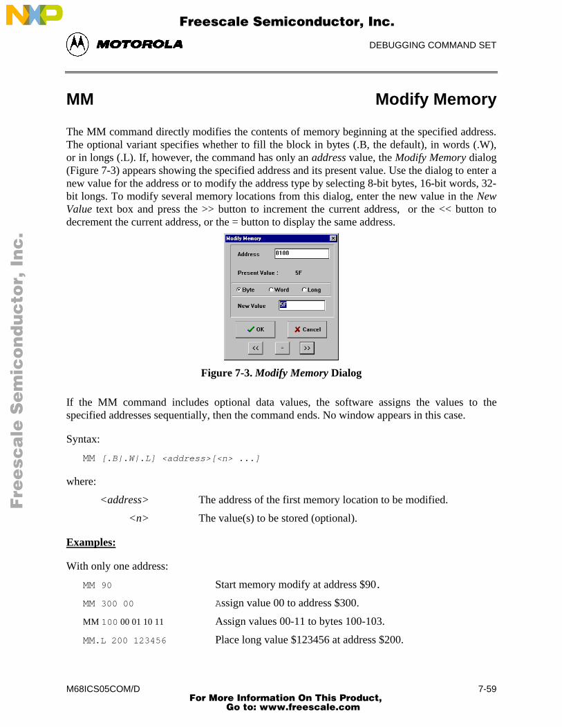
DEBUGGING COMMAND SET
M68ICS05COM/D 7-59
MM Modify Memory
The MM command directly modifies the contents of memory beginning at the specified address.The optional variant specifies whether to fill the block in bytes (.B, the default), in words (.W),or in longs (.L). If, however, the command has only an address value, the Modify Memory dialog(Figure 7-3) appears showing the specified address and its present value. Use the dialog to enter anew value for the address or to modify the address type by selecting 8-bit bytes, 16-bit words, 32-bit longs. To modify several memory locations from this dialog, enter the new value in the NewValue text box and press the >> button to increment the current address, or the << button todecrement the current address, or the = button to display the same address.
Figure 7-3. Modify Memory Dialog
If the MM command includes optional data values, the software assigns the values to thespecified addresses sequentially, then the command ends. No window appears in this case.
Syntax:
MM [.B|.W|.L] <address>[<n> ...]
where:
<address> The address of the first memory location to be modified.
<n> The value(s) to be stored (optional).
Examples:
With only one address:
MM 90 Start memory modify at address $90.
MM 300 00 Assign value 00 to address $300.
MM 100 00 01 10 11 Assign values 00-11 to bytes 100-103.
MM.L 200 123456 Place long value $123456 at address $200.
Fre
esc
ale
Se
mic
on
du
cto
r, I
Freescale Semiconductor, Inc.
For More Information On This Product, Go to: www.freescale.com
nc
...
DEBUGGING COMMAND SET
M68ICS05COM/D7-60
N Set/Clear Negative Bit
The N command sets or clears the N bit of the condition code register (CCR).
NOTE
The CCR bit designators are in the lower portion of the CPUwindow. The CCR pattern is 111HINZC (H is half-carry, I is IRQinterrupt mask, N is negative, Z is zero and C is carry). A letter inthese designators means that the corresponding bit of the CCR isset; a period means that the corresponding bit is clear.
Syntax:
N 0|1
Example:
N 1 Set the N bit of the CCR.
N 0 Clear the N bit of the CCR.
Fre
esc
ale
Se
mic
on
du
cto
r, I
Freescale Semiconductor, Inc.
For More Information On This Product, Go to: www.freescale.com
nc
...
DEBUGGING COMMAND SET
M68ICS05COM/D 7-61
NOBR Remove Breakpoints
The NOBR command removes one or all active breakpoints. If this command has an addressvalue, it removes the breakpoint at that address. If this command has no parameter values, itremoves all current breakpoints. To set breakpoints use the BR command.
An alternative way for clearing a breakpoint in the code window is to position the cursor on aline of code, then press the right mouse button and select Toggle Breakpoint at Cursor menuitem. This removes the breakpoint from the line.
Syntax:
NOBR [<address>]
where:
<address> Optional address of a single breakpoint to be removed.
Examples:
NOBR Remove all current instruction breakpoints.
NOBR 120 Remove the instruction breakpoint at address 120.
Fre
esc
ale
Se
mic
on
du
cto
r, I
Freescale Semiconductor, Inc.
For More Information On This Product, Go to: www.freescale.com
nc
...

DEBUGGING COMMAND SET
M68ICS05COM/D7-62
NOSYMBOL Clear User Symbols
The NOSYMBOL command removes all user defined symbols created using the SYMBOL frommemory. Symbols are created using the SYMBOL command. Symbols defined via a loadedMAP file are not affected.
Syntax:
NOSYMBOL
Example:
NOSYMBOL Clears user defined symbols and their definitions.
Fre
esc
ale
Se
mic
on
du
cto
r, I
Freescale Semiconductor, Inc.
For More Information On This Product, Go to: www.freescale.com
nc
...
DEBUGGING COMMAND SET
M68ICS05COM/D 7-63
PC Set Program Counter
The PC command assigns the specified value to the MCU program counter. As the PC alwayspoints to the address of the next instruction to be executed, assigning a new PC value changes theflow of code execution; the code windows change accordingly. The value entered with thecommand is displayed in the CPU Window.
An alternative way for setting the PC in a code window is to position the cursor on a line of code,then press the right mouse button and select the Set PC at Cursor menu item. This assigns theaddress of that line to the PC.
Syntax:
PC <address>
where:
<address> The new PC value.
Example:
PC 0200 Sets the PC value to 0200.
Fre
esc
ale
Se
mic
on
du
cto
r, I
Freescale Semiconductor, Inc.
For More Information On This Product, Go to: www.freescale.com
nc
...
DEBUGGING COMMAND SET
M68ICS05COM/D7-64
POD Change Serial Port
The POD command connects to the ICS05C circuit board through the specified serial (COM)port. If successful, this command responds with the current status of ports, reset, and IRQ pins onthe board. The command also shows the version of the board.
Syntax:
POD <n>
where:
<n> The number (1...8) of a serial port (COM1 through COM8) on thePC.
Example:
POD 1 Connect to serial port COM1.
Port A - 80
Port B - 00
Reset - 1
IRQ - 1
Version - 01
Fre
esc
ale
Se
mic
on
du
cto
r, I
Freescale Semiconductor, Inc.
For More Information On This Product, Go to: www.freescale.com
nc
...
DEBUGGING COMMAND SET
M68ICS05COM/D 7-65
PORTA or PRTA Set Port A Output Latches
The PORTA command assigns the specified value to the port A output register latches. (ThePRTA command is an alternate form of the PORTA command).
NOTE
If the ICS05C circuit board is connected, the system sends the nparameter value of this command to the board.
Syntax:
PORTA <n>
where:
<n> The new value for the port A output latches.
Example:
PORTA FF Set all port A output latches high.
Fre
esc
ale
Se
mic
on
du
cto
r, I
Freescale Semiconductor, Inc.
For More Information On This Product, Go to: www.freescale.com
nc
...
DEBUGGING COMMAND SET
M68ICS05COM/D7-66
PORTB or PRTB Set Port B Output Latches
The PORTB command assigns the specified value to the port B output register latches. (ThePRTB command is an alternate form of the PORTB command).
NOTES
If the ICS05C circuit board is connected, the system sends the nparameter value of this command to the board.
Syntax:
PORTB <n>
where:
<n> The new value for the port B output latches.
Example:
PORTB 03 Set the port B output latches to 03.
Fre
esc
ale
Se
mic
on
du
cto
r, I
Freescale Semiconductor, Inc.
For More Information On This Product, Go to: www.freescale.com
nc
...
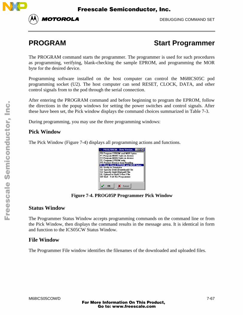
DEBUGGING COMMAND SET
M68ICS05COM/D 7-67
PROGRAM Start Programmer
The PROGRAM command starts the programmer. The programmer is used for such proceduresas programming, verifying, blank-checking the sample EPROM, and programming the MORbyte for the desired device.
Programming software installed on the host computer can control the M68ICS05C podprogramming socket (U2). The host computer can send RESET, CLOCK, DATA, and othercontrol signals from to the pod through the serial connection.
After entering the PROGRAM command and before beginning to program the EPROM, followthe directions in the popup windows for setting the power switches and control signals. Afterthese have been set, the Pick window displays the command choices summarized in Table 7-3.
During programming, you may use the three programming windows:
Pick Window
The Pick Window (Figure 7-4) displays all programming actions and functions.
Figure 7-4. PROG05P Programmer Pick Window
Status Window
The Programmer Status Window accepts programming commands on the command line or fromthe Pick Window, then displays the command results in the message area. It is identical in formand function to the ICS05CW Status Window.
File Window
The Programmer File window identifies the filenames of the downloaded and uploaded files.
Fre
esc
ale
Se
mic
on
du
cto
r, I
Freescale Semiconductor, Inc.
For More Information On This Product, Go to: www.freescale.com
nc
...
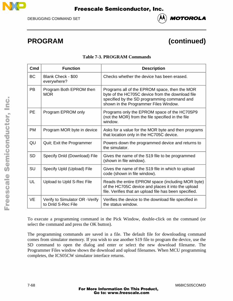
DEBUGGING COMMAND SET
M68ICS05COM/D7-68
PROGRAM (continued)
Table 7-3. PROGRAM Commands
Cmd Function Description
BC Blank Check - $00everywhere?
Checks whether the device has been erased.
PB Program Both EPROM thenMOR
Programs all of the EPROM space, then the MORbyte of the HC705C device from the download filespecified by the SD programming command andshown in the Programmer Files Window.
PE Program EPROM only Programs only the EPROM space of the HC705P9(not the MOR) from the file specified in the filewindow.
PM Program MOR byte in device Asks for a value for the MOR byte and then programsthat location only in the HC705C device.
QU Quit; Exit the Programmer Powers down the programmed device and returns tothe simulator.
SD Specify Dnld (Download) File Gives the name of the S19 file to be programmed(shown in file window).
SU Specify Upld (Upload) File Gives the name of the S19 file in which to uploadcode (shown in file window).
UL Upload to Upld S-Rec File Reads the entire EPROM space (including MOR byte)of the HC705C device and places it into the uploadfile. Verifies that an upload file has been specified.
VE Verify to Simulator OR -Verifyto Dnld S-Rec File
Verifies the device to the download file specified inthe status window.
To execute a programming command in the Pick Window, double-click on the command (orselect the command and press the OK button).
The programming commands are saved in a file. The default file for downloading commandcomes from simulator memory. If you wish to use another S19 file to program the device, use theSD command to open the dialog and enter or select the new download filename. TheProgrammer Files window shows the download and upload filenames. When MCU programmingcompletes, the ICS05CW simulator interface returns.
Fre
esc
ale
Se
mic
on
du
cto
r, I
Freescale Semiconductor, Inc.
For More Information On This Product, Go to: www.freescale.com
nc
...
DEBUGGING COMMAND SET
M68ICS05COM/D 7-69
PROGRAM (continued)
Syntax:
PROGRAM
Example:
PROGRAM Starts the programmer.
Fre
esc
ale
Se
mic
on
du
cto
r, I
Freescale Semiconductor, Inc.
For More Information On This Product, Go to: www.freescale.com
nc
...
DEBUGGING COMMAND SET
M68ICS05COM/D7-70
R Use Register Files
The R command pulls up windows for the register files (sold separately by P&E) and startsinteractive setup of such system registers as the I/O, timer, and COP.
Entering this command opens the register files window, which can present a list of register filesfor the device (if set up previously). Selecting a file brings up a display of values and significancefor each bit of the register. The user can view any of the registers, modify their values, and storethe results back into memory.
An alternate way to bring up the register files window is to press the Register Files speed button.
Syntax:
R
Example:
R Start interactive system register setup.
Fre
esc
ale
Se
mic
on
du
cto
r, I
Freescale Semiconductor, Inc.
For More Information On This Product, Go to: www.freescale.com
nc
...
DEBUGGING COMMAND SET
M68ICS05COM/D 7-71
REG Show Registers
The REG command displays the contents of the CPU registers in the Status window. (TheSTATUS command is identical to the REG command.)
Syntax:
REG
Example:
REG Displays the contents of the CPU registers.
Fre
esc
ale
Se
mic
on
du
cto
r, I
Freescale Semiconductor, Inc.
For More Information On This Product, Go to: www.freescale.com
nc
...
DEBUGGING COMMAND SET
M68ICS05COM/D7-72
REM Place Comment in Batch/Macro File
The REM command lets you display comments in a macro file. When the macro file executes,the text comment appears in the status window.
Syntax:
REM <text>
where:
<text> A comment to be displayed when a macro file is executing.
Example:
REM Program executing; Display the message Program executing during macrofile execution.
Fre
esc
ale
Se
mic
on
du
cto
r, I
Freescale Semiconductor, Inc.
For More Information On This Product, Go to: www.freescale.com
nc
...
DEBUGGING COMMAND SET
M68ICS05COM/D 7-73
RESET Simulate Processor Reset
The RESET command simulates a reset of the MCU and sets the program counter (PC) to thecontents of the reset vector. This command does not start execution of user code. (To reset andexecute code, use the RESETGO command.)
Syntax:
RESET
Example:
RESET Simulate reset of the MCU.
Fre
esc
ale
Se
mic
on
du
cto
r, I
Freescale Semiconductor, Inc.
For More Information On This Product, Go to: www.freescale.com
nc
...
DEBUGGING COMMAND SET
M68ICS05COM/D7-74
RESETGO Reset and Restart MCU
The RESETGO command simulates a reset of the MCU, sets the program counter (PC) to thecontents of the reset vector, then starts execution from that address.
Syntax:
RESETGO
Example:
RESETGO Simulate reset of the MCU and start execution of code.
Fre
esc
ale
Se
mic
on
du
cto
r, I
Freescale Semiconductor, Inc.
For More Information On This Product, Go to: www.freescale.com
nc
...
DEBUGGING COMMAND SET
M68ICS05COM/D 7-75
SAVEDESK Save Desktop Settings
The SAVEDESK command saves window position, size, and other desktop settings. Opening theapplication or entering the LOADDESK command loads the saved settings.
Syntax:
SAVEDESK
Example:
SAVEDESK Save window settings for the application.
Fre
esc
ale
Se
mic
on
du
cto
r, I
Freescale Semiconductor, Inc.
For More Information On This Product, Go to: www.freescale.com
nc
...
DEBUGGING COMMAND SET
M68ICS05COM/D7-76
SHOWBREAKS Display Breakpoint Window
The SHOWBREAKS command brings up the Breakpoint Window that displays the breakpointsused in the current debugging session. Breakpoints can be modified through this window
Syntax:
SHOWBREAKS
Example:
SHOWBREAKS Open the breakpoint window.
Fre
esc
ale
Se
mic
on
du
cto
r, I
Freescale Semiconductor, Inc.
For More Information On This Product, Go to: www.freescale.com
nc
...
DEBUGGING COMMAND SET
M68ICS05COM/D 7-77
SHOWCODE Display Code at Address
The SHOWCODE command displays code in the code windows beginning at the specifiedaddress, without changing the value of the program counter (PC). The code window shows eithersource code or disassembly from the given address, depending on which mode is selected for thewindow. This command is useful for browsing through various modules in the program. Toreturn to code where the PC is pointing, use the SHOWPC command.
Syntax:
SHOWCODE <address>
where:
<address> The address or label where code is to be shown.
Example:
SHOWCODE 200 Show code starting at location $200.
Fre
esc
ale
Se
mic
on
du
cto
r, I
Freescale Semiconductor, Inc.
For More Information On This Product, Go to: www.freescale.com
nc
...
DEBUGGING COMMAND SET
M68ICS05COM/D7-78
SHOWMAP Show Information in Map File
The SHOWMAP command lets you view information from the current map file stored in thememory. All symbols defined in the source code used for debugging will be listed. The debuggerdefined symbols, defined with the SYMBOL command, will not be shown. The MAP commandis identical to the SHOWMAP command.
Syntax:
SHOWMAP
Example:
SHOWMAP Shows symbols from the loaded map file and their values.
Fre
esc
ale
Se
mic
on
du
cto
r, I
Freescale Semiconductor, Inc.
For More Information On This Product, Go to: www.freescale.com
nc
...
DEBUGGING COMMAND SET
M68ICS05COM/D 7-79
SHOWTRACE Display Trace Window
The SHOWTRACE command displays the trace window, showing the last 1024 instructions thatwere executed after the TRACE command is used.
Syntax:
SHOWTRACE
Example:
SHOWTRACE Open the trace window.
Fre
esc
ale
Se
mic
on
du
cto
r, I
Freescale Semiconductor, Inc.
For More Information On This Product, Go to: www.freescale.com
nc
...
DEBUGGING COMMAND SET
M68ICS05COM/D7-80
SNAPSHOT Save Window Data to Log File
The SNAPSHOT command sends textual information about the debugger windows to the openlog file. If no log file is open, the command has no effect.
Syntax:
SNAPSHOT
Example:
SNAPSHOT Save window data to the log file.
Fre
esc
ale
Se
mic
on
du
cto
r, I
Freescale Semiconductor, Inc.
For More Information On This Product, Go to: www.freescale.com
nc
...
DEBUGGING COMMAND SET
M68ICS05COM/D 7-81
SP Set Stack Pointer
The SP command assigns the specified value to the stack pointer (SP) used by the CPU. Thevalue entered with the command should be reflected in the CPU Window.
Syntax:
SP <n>
where:
<n> The new stack pointer value.
Example:
SP $E0 Set the stack pointer value to $E0.
Fre
esc
ale
Se
mic
on
du
cto
r, I
Freescale Semiconductor, Inc.
For More Information On This Product, Go to: www.freescale.com
nc
...
DEBUGGING COMMAND SET
M68ICS05COM/D7-82
SS Execute Source Step(s)
The SS command steps through a specified number of source code instructions, beginning at thecurrent program counter (PC) address value, then halts. All windows are refreshed as eachinstruction is executed. This makes the SS command useful for high level language compilers(such as C) so that the user can step through compiler source code instead of assemblyinstructions.
If the number argument is omitted, one source instruction is executed. If the SS command isentered with an n value, the command steps through n source instructions.
Syntax:
SS [<n>]
where:
<n> number of instructions to step through.
Examples:
SS Step through the instruction at the PC address value.
SS 8 Step through eight instructions, starting at the current PCaddress value.
Fre
esc
ale
Se
mic
on
du
cto
r, I
Freescale Semiconductor, Inc.
For More Information On This Product, Go to: www.freescale.com
nc
...
DEBUGGING COMMAND SET
M68ICS05COM/D 7-83
ST or STEP or T Execute Single Step
The STEP command steps through a specified number of assembly instructions, beginning at thecurrent program counter (PC) address value, then halts. All windows are refreshed as eachinstruction is executed. If the number argument is omitted, one instruction is executed. If youenter the STEP command with a parameter value, the command steps through that manyinstructions. (The ST and T commands are identical to the STEP command.)
Syntax:
STEP [<n>]
where:
<n> The hexadecimal number of instructions to be executed by eachcommand.
Examples:
STEP Execute the assembly instruction at the PC address value.
ST 2 Execute two assembly instructions, starting at the PCaddress value.
Fre
esc
ale
Se
mic
on
du
cto
r, I
Freescale Semiconductor, Inc.
For More Information On This Product, Go to: www.freescale.com
nc
...
DEBUGGING COMMAND SET
M68ICS05COM/D7-84
STACK Show Stack Window
The STACK command opens the HC05 Stack Window, which shows the stack pointer (SP)value, data stored on the stack, and results of an RTS or RTI instruction.
Syntax:
STACK
Example:
STACK Open the stack window.
Fre
esc
ale
Se
mic
on
du
cto
r, I
Freescale Semiconductor, Inc.
For More Information On This Product, Go to: www.freescale.com
nc
...
DEBUGGING COMMAND SET
M68ICS05COM/D 7-85
STEPFOR Step Forever
The STEPFOR command continuously executes instructions, one at a time, beginning at thecurrent Program Counter (PC) address. Execution continues until an error condition occurs, untilit reaches a breakpoint, or until you press a key or the Stop button on the ICS05CW toolbar. Allwindows are refreshed as each instruction is executed.
Syntax:
STEPFOR
Example:
STEPFOR Step through instructions continuously.
Fre
esc
ale
Se
mic
on
du
cto
r, I
Freescale Semiconductor, Inc.
For More Information On This Product, Go to: www.freescale.com
nc
...
DEBUGGING COMMAND SET
M68ICS05COM/D7-86
STEPTIL Step Until Address
The STEPTIL command continuously steps through instructions beginning at the currentprogram counter (PC) address until the PC value reaches the specified address. Executioncontinues to the specified address or until you press a key or the Stop button on the ICS05CWtoolbar, or it reaches a breakpoint, or until an error occurs.
Syntax:
STEPTIL <address>
where:
<address> Execution stop address. This must be an instruction address.
Example:
STEPTIL 0200 Execute instructions continuously until PC value is 0200.
Fre
esc
ale
Se
mic
on
du
cto
r, I
Freescale Semiconductor, Inc.
For More Information On This Product, Go to: www.freescale.com
nc
...
DEBUGGING COMMAND SET
M68ICS05COM/D 7-87
SYMBOL Add Symbol
The SYMBOL command creates a new symbol, which can be used anywhere in the debugger, inplace of the symbol value. If this command is entered with no parameters, it will list the currentuser-defined symbols. If parameters are specified, the SYMBOL command will create a newsymbol.
The symbol label is case-insensitive and has a maximum length of 16T. It can be used with theASM and MM commands and replaces all addresses in the Code and Variables windows.
Syntax:
SYMBOL [<label> <value>]
where:
<label> The ASCII-character string label of the new symbol.
<value> The value of the new symbol (label).
Examples:
SYMBOL Show the current user-defined symbols.
SYMBOL timer_control $08 Define new symbol “timer_control”, with value$08. Subsequently, to modify the value of“timer_control”, enter the command:MM timer_control new_value
Fre
esc
ale
Se
mic
on
du
cto
r, I
Freescale Semiconductor, Inc.
For More Information On This Product, Go to: www.freescale.com
nc
...
DEBUGGING COMMAND SET
M68ICS05COM/D7-88
TRACE Enable/Disable Tracing
The TRACE command enables or disables instruction captures. When tracing is enabled, thedebugger records instructions in a 1024-element circular buffer. Note that tracing slowsexecution somewhat.
The debugger disassembles captured information when buffer contents are viewed through thetrace window. To view tracing results, use the SHOWTRACE command. If tracing is not enabledor if a trace slot is empty, the Trace Window will display the message No Trace Available. Toclear the Trace Window, toggle tracing OFF and then ON using the TRACE command.
Syntax:
TRACE
Example:
TRACE Enable (or disable) instruction tracing.
Fre
esc
ale
Se
mic
on
du
cto
r, I
Freescale Semiconductor, Inc.
For More Information On This Product, Go to: www.freescale.com
nc
...
DEBUGGING COMMAND SET
M68ICS05COM/D 7-89
UPLOAD_SREC Upload S Record to Screen
The UPLOAD_SREC command uploads the contents of the specified memory block (range), in.S19 object file format, displaying the contents in the status window. If a log file is opened,UPLOAD_SREC puts the information into the log file as well.
NOTE
If the UPLOAD_SREC command is entered, sometimes thememory contents scroll through the debug window too rapidly toview. Accordingly, either the LOGFILE command should be used,which records the contents into a file, or use the scroll bars in thestatus window.
Syntax:
UPLOAD_SREC <startrange> <endrange>
where:
<startrange> Beginning address of the memory block.
<endrange> Ending address of the memory block (range)
Example:
UPLOAD_SREC 300 7FF Upload the 300-7FF memory block in .S19 format.
Fre
esc
ale
Se
mic
on
du
cto
r, I
Freescale Semiconductor, Inc.
For More Information On This Product, Go to: www.freescale.com
nc
...
DEBUGGING COMMAND SET
M68ICS05COM/D7-90
VAR Display Variable
The VAR command displays the specified address and its contents in the Variables window forviewing during code execution. Variants of the command display a byte, a word, a long, or astring. As the value at the address changes, the variables window updates the value. Themaximum number of variables is 32.
In ASCII displays of variables, control characters or other non-printing characters appear asperiods (.). Byte, word, long, or string variants determine the display format:
• Byte (.B): hexadecimal and binary (the default)
• Word (.W): hexadecimal and decimal
• Long (.L): hexadecimal and decimal
• String (.S): ASCII characters
The optional <n> parameter specifies the number of string characters to be displayed; the defaultvalue is 1. The <n> parameter has no effect for byte, word, or long values.
Syntax:
VAR [.B|.W|.L|.S] <address> [<n>]
where:
<address> The address of the memory variable.
<n> Optional number of characters for a string variable; default value is1, does not apply to byte or word variables.
Examples:
VAR C0 Show byte value of address C0 (hex and binary)
VAR.B D4 Show byte value of address D4 (hex and binary)
VAR.W E0 Show word value of address E0 (hex & decimal)
VAR.S C0 5 Show the five-character ASCII string at address C0
Fre
esc
ale
Se
mic
on
du
cto
r, I
Freescale Semiconductor, Inc.
For More Information On This Product, Go to: www.freescale.com
nc
...
DEBUGGING COMMAND SET
M68ICS05COM/D 7-91
VERSION or VER Display Software Version
The VERSION command displays the version and date of the software. (VER is an alternateform of this command.)
Syntax:
VERSION
Examples:
VERSION Display version and date of the software.
VER Display version and date of the software.
Fre
esc
ale
Se
mic
on
du
cto
r, I
Freescale Semiconductor, Inc.
For More Information On This Product, Go to: www.freescale.com
nc
...
DEBUGGING COMMAND SET
M68ICS05COM/D7-92
WAIT Wait for n Cycles
The WAIT command delays simulator command execution by the specified number of cycles.This command is used in MACRO files to control when inputs come into the simulator. If aWAIT command is encountered, control is passed back to the keyboard. Then the macro fileexecution waits for a command to be entered such as GO or STEP, which starts MCU executiononce again. As soon as the number of cycles that pass is equal to the <n> value of the WAITcommand, the simulator resumes executing commands of the macro file until another WAIT isencountered or the two mentioned conditions happens again.
Syntax:
WAIT <n>
where:
<n> The hexadecimal number of cycles to wait.
Example:
WAIT A Delay command execution for 10 MCU cycles.
Fre
esc
ale
Se
mic
on
du
cto
r, I
Freescale Semiconductor, Inc.
For More Information On This Product, Go to: www.freescale.com
nc
...
DEBUGGING COMMAND SET
M68ICS05COM/D 7-93
WHEREIS Display Symbol Value
The WHEREIS command displays the value of the specified symbol. Symbol names are definedthrough source code or the SYMBOL command. Alternatively, this command returns the symbolat a specified address.
Syntax:
WHEREIS <symbol> | <address>
where:
<symbol> A symbol listed in the symbol table.
<address> Address for which a symbol is defined.
Examples:
WHEREIS START Display the symbol START and its value.
WHEREIS 0300 Display the value 0300 and its symbol name if any.
Fre
esc
ale
Se
mic
on
du
cto
r, I
Freescale Semiconductor, Inc.
For More Information On This Product, Go to: www.freescale.com
nc
...

DEBUGGING COMMAND SET
M68ICS05COM/D7-94
X or XREG Set X Register Value
The X command sets the index (X) register to the specified value. The value entered with thecommand is displayed in the CPU Window. (The X command is identical to the XREGcommand.)
Syntax:X <value>
where:<value> The new value for the X register.
Examples:
X 05 Set the index register value to 05.XREG F0 Set the index register value to F0.
Fre
esc
ale
Se
mic
on
du
cto
r, I
Freescale Semiconductor, Inc.
For More Information On This Product, Go to: www.freescale.com
nc
...
DEBUGGING COMMAND SET
M68ICS05COM/D 7-95
Z Set/Clear Zero Bit
The Z command sets or clears the Z bit in the condition code register (CCR).
NOTE
The CCR bit designators are in the lower portion of the CPUwindow. The CCR pattern is 111HINZC (H is half-carry, I is IRQinterrupt mask, N is negative, Z is zero and C is carry). A letter inthese designators means that the corresponding bit of the CCR isset; a period means that the corresponding bit is clear.
Syntax:
Z 0|1
Examples:
Z 0 Clear the Z bit of the CCR.
Z 1 Set the Z bit of the CCR.
Fre
esc
ale
Se
mic
on
du
cto
r, I
Freescale Semiconductor, Inc.
For More Information On This Product, Go to: www.freescale.com
nc
...

DEBUGGING COMMAND SET
M68ICS05COM/D7-96
Fre
esc
ale
Se
mic
on
du
cto
r, I
Freescale Semiconductor, Inc.
For More Information On This Product, Go to: www.freescale.com
nc
...
EXAMPLE PROJECT
M68ICS05COM/D 8-1
CHAPTER 8
EXAMPLE PROJECT
8.1 OVERVIEW
This section provides information that will guide you through a first-time use of the ICS05CWsoftware and through a typical setup of the WinIDE.
8.2 SETTING UP A SAMPLE PROJECT
To demonstrate how source code to be assembled is handled using the ICS05CW simulator,WinIDE editor, and CASM05W assembler software as an integrated development environment,consider as an example the following typical project.
NOTE
The sample files referred to are referenced for illustration purposesonly and are not provided with the software. Create your own*.ASM files for your projects using the ICS05CW softwarecomponents. For information about using files created by otherassemblers, see paragraph 5.4.4.
8.2.1 Set Up the Environment
To begin the project, start the WinIDE editor and establish the desktop and environment settingsfor the project:
1. Start the WinIDE editor by selecting the icon from the Windows 95 Start Menu or bydouble-clicking on the icon ICS05CW Program Group in the Windows 3.1 ProgramManager.
2. In the WinIDE editor, choose the Setup Environment option from the File menu toopen the Environment Settings dialog.
Fre
esc
ale
Se
mic
on
du
cto
r, I
Freescale Semiconductor, Inc.
For More Information On This Product, Go to: www.freescale.com
nc
...
EXAMPLE PROJECT
M68ICS05COM/D8-2
3. Enter environment options for the modules of the WinIDE development environment,represented by the General Editor, General Environment, EXE1, EXE2, andAssembler/Compiler tabs. For the example project:
a. In the General Environment tab, choose the environment options you prefer.In the %FILE% Parameter passed to external program is text box, enter thepath and filename (MAIN.ASM).
b. In the General Editor tab, choose the editing options you prefer.
c. In the EXE1 tab, make sure the EXE Path text box points to theICS05CW.EXE path and filename, and that the Options text box indicates theproper communications port (if the pod is to be used).
d. In the Assembler/Compiler tab, make sure these options are selected:
• The EXE Path text box indicates the path and filename for theCASM05W.EXE.
• The Type text box specifies the P&E CASMW Assembler.
• To view the CASM05W window during assembly, check the ShowAssembler Progress option in the Assembly Preferences section of thetab.
4. Press the OK button to save the settings made in the Environment Settings dialog tabsand close the dialog.
You have now set up the environment for your project. To save it for later use:
1. In the WinIDE, select the Save Project As option from the Environment menu.
2. In the dialog box, enter a path and a descriptive project filename with the PPFextension. Place the project file in the directory where the source files will be located.
8.2.2 Create the Source Files
Create new or edit existing source code files using the WinIDE editor:
1. From the File menu, choose the New File option to create a blank source window inwhich you can enter source code (or open an existing file using the Open File option).You can all the source code files in the WinIDE editor and work on themindividually.
2. When you have created the new file or edited the existing file, from the File menu,choose the Save File option to assign a path and filename to the source file (or choosethe Save File As option to assign a new path and filename to an existing file).
3. Create all the source code files required for the project.
Fre
esc
ale
Se
mic
on
du
cto
r, I
Freescale Semiconductor, Inc.
For More Information On This Product, Go to: www.freescale.com
nc
...
EXAMPLE PROJECT
M68ICS05COM/D 8-3
The example project consists of 12 source code files created in the WinIDE editor. The files arethen assembled into *.ASM files using WinIDE Assemble/Compile toolbar button. The 12 filesare then listed in a separate file MAIN.ASM.
The MAIN.ASM file consists of $INCLUDE functions, each followed by the filename for thesource code file, followed by an optional comment describing the function of the code in thatfile. Using the $INCLUDE function in a main file lets you organize your source code logicallyinto a number of small files, ultimately making it easier to develop, manage, and work with thesource code. For more information about using the $INCLUDE function, see paragraph 5.6.4.
The example MAIN.ASM file:
***********************************************************Include files***********************************************************$include "equates.asm"$include "init.asm"$include "charge.asm"$include "dcharge.asm"$include "options.asm"$include "misc.asm"$include "readv.asm"$include "isr.asm"$include "display.asm"$include "eeprom.asm"$include "text.asm"$include "vectors.asm"
8.2.3 Assemble the Project
Now you are ready to assemble your project. In the WinIDE, follow these steps:
1. With the MAIN.ASM file in the active window, press the Assemble/Compile Filebutton (third button from the left) on the WinIDE toolbar to start the assembler fromthe WinIDE editor.
2. The assembler concatenates the files in the source code window, assembles them, andcreates the output MAIN.ASM file. MAIN.ASM replaces any previous assembly codefile of the same name in the same directory.
3. If the assembler encounters errors during assembly, the assembler stops and the firsterror is displayed highlighted in red in the source file. To correct the errors, click onthe Debugger (EXE1) toolbar button (left-most button) on the WinIDE toolbar toopen or move to the ICS05CW simulator to debug the source code. When you havefinished debugging the code in the ICS05CW simulator, return to the WinIDE editorby clicking the Back to Editor button (the left-most button) in the ICS05CW toolbar.
4. Continue assembling, debugging, and editing the source files until the assemblycompletes successfully.
Fre
esc
ale
Se
mic
on
du
cto
r, I
Freescale Semiconductor, Inc.
For More Information On This Product, Go to: www.freescale.com
nc
...
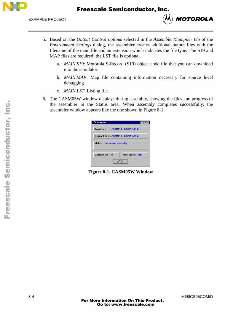
EXAMPLE PROJECT
M68ICS05COM/D8-4
5. Based on the Output Control options selected in the Assembler/Compiler tab of theEnvironment Settings dialog, the assembler creates additional output files with thefilename of the main file and an extension which indicates the file type. The S19 andMAP files are required; the LST file is optional.
a. MAIN.S19: Motorola S-Record (S19) object code file that you can downloadinto the simulator.
b. MAIN.MAP: Map file containing information necessary for source leveldebugging
c. MAIN.LST: Listing file.
6. The CASM05W window displays during assembly, showing the files and progress ofthe assembler in the Status area. When assembly completes successfully, theassembler window appears like the one shown in Figure 8-1.
Figure 8-1. CASM05W Window
Fre
esc
ale
Se
mic
on
du
cto
r, I
Freescale Semiconductor, Inc.
For More Information On This Product, Go to: www.freescale.com
nc
...
S-RECORD INFORMATION
M68ICS05COM/D A-1
APPENDIX A
S-RECORD INFORMATION
A.1 OVERVIEW
The Motorola S-record format was devised for the purpose of encoding programs or data files ina printable format for transport between computer platforms. The format also provides for editingof the S-records and monitoring the cross-platform transfer process.
A.2 S-RECORD CONTENT
Each S-record is a character string composed of several fields which identify:
• record type
• record length
• memory address
• code/data
• checksum
Each byte of binary data is encoded in the s-record as a two-character hexadecimal number:
• The first character represents the high-order four bits of the byte
• The second character represents the low-order four bits of the byte
The five fields that comprise an S-record are shown in the Table A-1.
Table A-1. S-Record Fields
TYPE RECORD LENGTH ADDRESS CODE/DATA CHECKSUM
Fre
esc
ale
Se
mic
on
du
cto
r, I
Freescale Semiconductor, Inc.
For More Information On This Product, Go to: www.freescale.com
nc
...
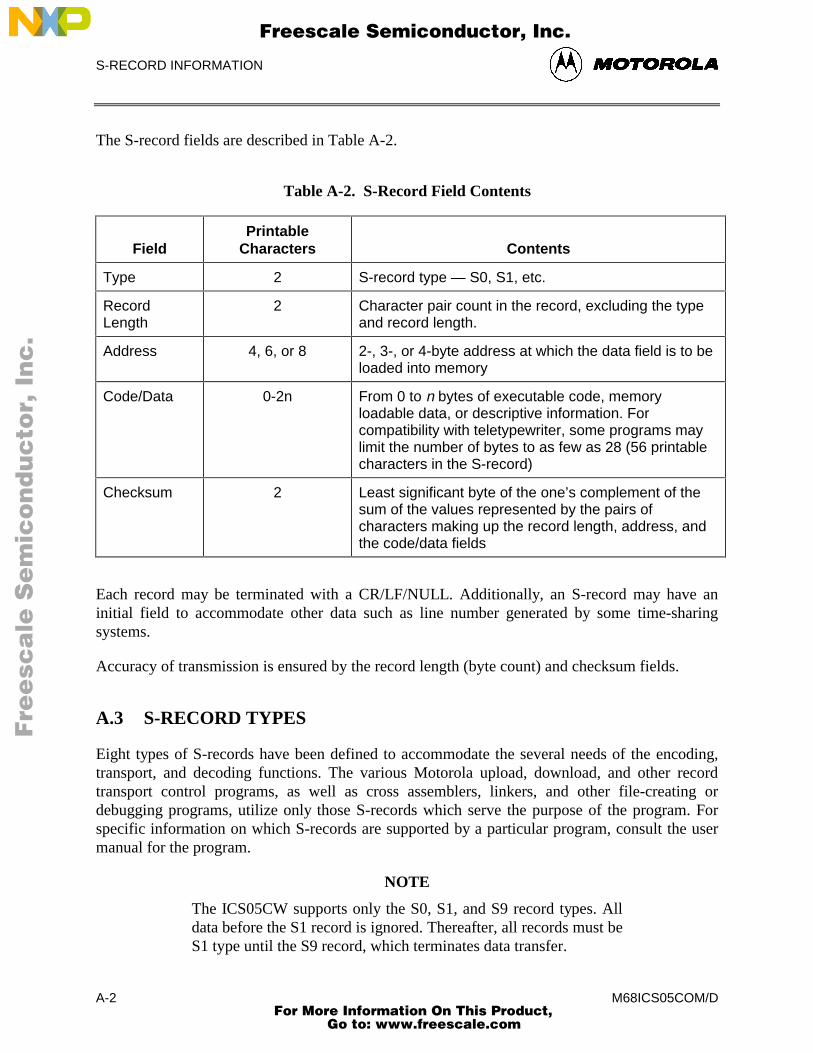
S-RECORD INFORMATION
M68ICS05COM/DA-2
The S-record fields are described in Table A-2.
Table A-2. S-Record Field Contents
FieldPrintable
Characters Contents
Type 2 S-record type — S0, S1, etc.
RecordLength
2 Character pair count in the record, excluding the typeand record length.
Address 4, 6, or 8 2-, 3-, or 4-byte address at which the data field is to beloaded into memory
Code/Data 0-2n From 0 to n bytes of executable code, memoryloadable data, or descriptive information. Forcompatibility with teletypewriter, some programs maylimit the number of bytes to as few as 28 (56 printablecharacters in the S-record)
Checksum 2 Least significant byte of the one’s complement of thesum of the values represented by the pairs ofcharacters making up the record length, address, andthe code/data fields
Each record may be terminated with a CR/LF/NULL. Additionally, an S-record may have aninitial field to accommodate other data such as line number generated by some time-sharingsystems.
Accuracy of transmission is ensured by the record length (byte count) and checksum fields.
A.3 S-RECORD TYPES
Eight types of S-records have been defined to accommodate the several needs of the encoding,transport, and decoding functions. The various Motorola upload, download, and other recordtransport control programs, as well as cross assemblers, linkers, and other file-creating ordebugging programs, utilize only those S-records which serve the purpose of the program. Forspecific information on which S-records are supported by a particular program, consult the usermanual for the program.
NOTE
The ICS05CW supports only the S0, S1, and S9 record types. Alldata before the S1 record is ignored. Thereafter, all records must beS1 type until the S9 record, which terminates data transfer.
Fre
esc
ale
Se
mic
on
du
cto
r, I
Freescale Semiconductor, Inc.
For More Information On This Product, Go to: www.freescale.com
nc
...
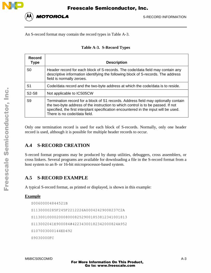
S-RECORD INFORMATION
M68ICS05COM/D A-3
An S-record format may contain the record types in Table A-3.
Table A-3. S-Record Types
RecordType Description
S0 Header record for each block of S-records. The code/data field may contain anydescriptive information identifying the following block of S-records. The addressfield is normally zeroes.
S1 Code/data record and the two-byte address at which the code/data is to reside.
S2-S8 Not applicable to ICS05CW
S9 Termination record for a block of S1 records. Address field may optionally containthe two-byte address of the instruction to which control is to be passed. If notspecified, the first interplant specification encountered in the input will be used.There is no code/data field.
Only one termination record is used for each block of S-records. Normally, only one headerrecord is used, although it is possible for multiple header records to occur.
A.4 S-RECORD CREATION
S-record format programs may be produced by dump utilities, debuggers, cross assemblers, orcross linkers. Several programs are available for downloading a file in the S-record format from ahost system to an 8- or 16-bit microprocessor-based system.
A.5 S-RECORD EXAMPLE
A typical S-record format, as printed or displayed, is shown in this example:
Example
S00600004844521B
S1130000285F245F2212226A00042429008237C2A
S11300100002000800082529001853812341001813
S113002041E900084#42234300182342000824A952
S107003000144ED492
S9030000FC
Fre
esc
ale
Se
mic
on
du
cto
r, I
Freescale Semiconductor, Inc.
For More Information On This Product, Go to: www.freescale.com
nc
...
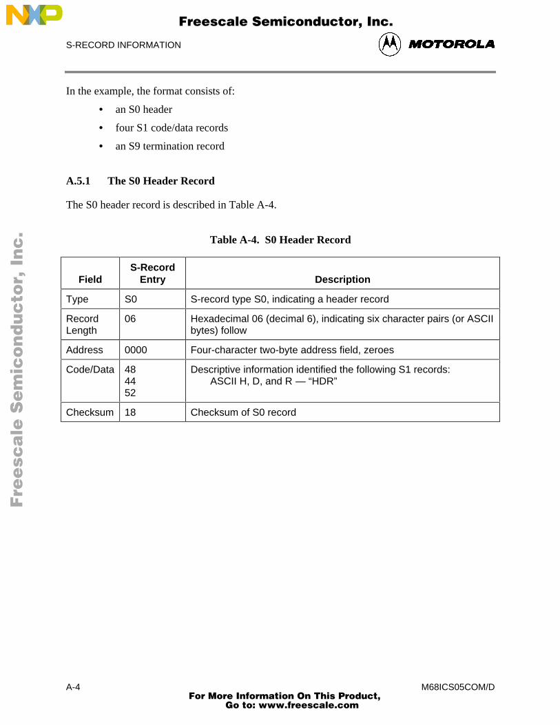
S-RECORD INFORMATION
M68ICS05COM/DA-4
In the example, the format consists of:
• an S0 header
• four S1 code/data records
• an S9 termination record
A.5.1 The S0 Header Record
The S0 header record is described in Table A-4.
Table A-4. S0 Header Record
FieldS-Record
Entry Description
Type S0 S-record type S0, indicating a header record
RecordLength
06 Hexadecimal 06 (decimal 6), indicating six character pairs (or ASCIIbytes) follow
Address 0000 Four-character two-byte address field, zeroes
Code/Data 484452
Descriptive information identified the following S1 records: ASCII H, D, and R — “HDR”
Checksum 18 Checksum of S0 record
Fre
esc
ale
Se
mic
on
du
cto
r, I
Freescale Semiconductor, Inc.
For More Information On This Product, Go to: www.freescale.com
nc
...
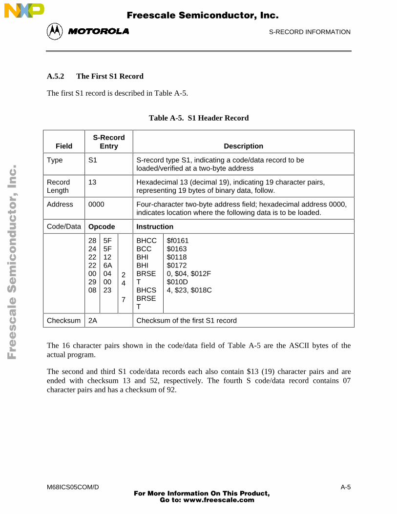
S-RECORD INFORMATION
M68ICS05COM/D A-5
A.5.2 The First S1 Record
The first S1 record is described in Table A-5.
Table A-5. S1 Header Record
FieldS-Record
Entry Description
Type S1 S-record type S1, indicating a code/data record to beloaded/verified at a two-byte address
RecordLength
13 Hexadecimal 13 (decimal 19), indicating 19 character pairs,representing 19 bytes of binary data, follow.
Address 0000 Four-character two-byte address field; hexadecimal address 0000,indicates location where the following data is to be loaded.
Code/Data Opcode Instruction
28242222002908
5F5F126A040023
24
7
BHCCBCCBHIBHIBRSETBHCSBRSET
$f0161$0163$0118$01720, $04, $012F$010D4, $23, $018C
Checksum 2A Checksum of the first S1 record
The 16 character pairs shown in the code/data field of Table A-5 are the ASCII bytes of theactual program.
The second and third S1 code/data records each also contain $13 (19) character pairs and areended with checksum 13 and 52, respectively. The fourth S code/data record contains 07character pairs and has a checksum of 92.
Fre
esc
ale
Se
mic
on
du
cto
r, I
Freescale Semiconductor, Inc.
For More Information On This Product, Go to: www.freescale.com
nc
...
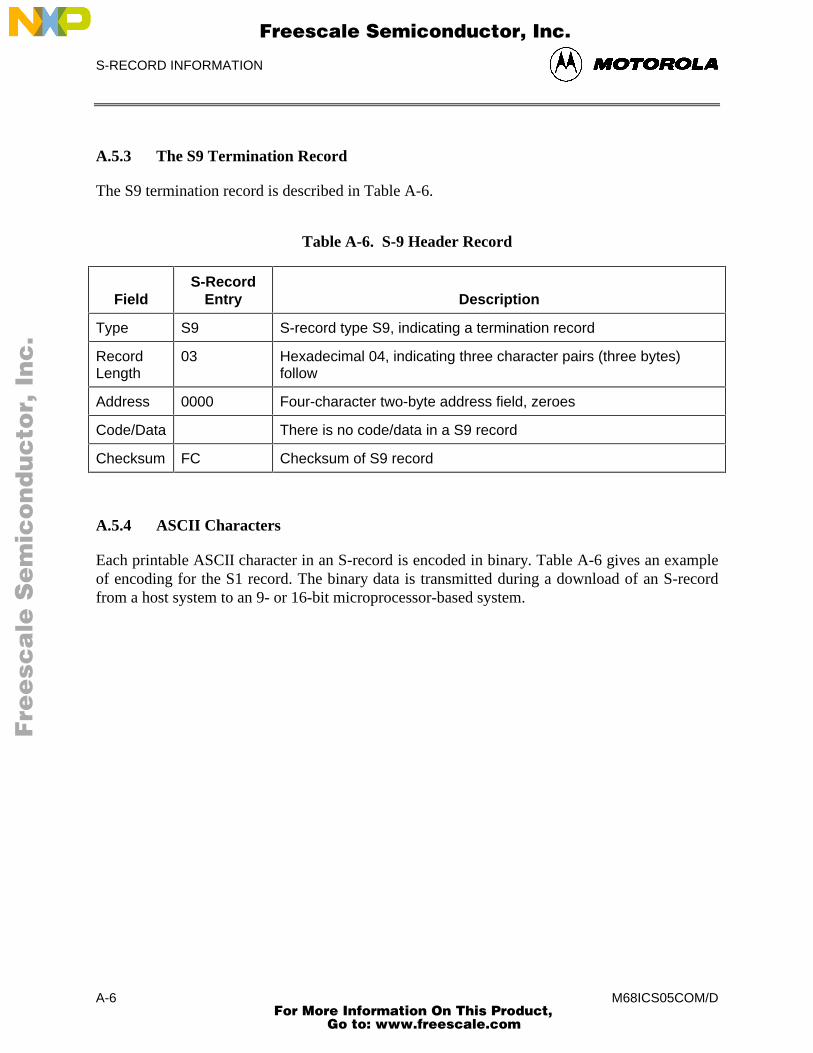
S-RECORD INFORMATION
M68ICS05COM/DA-6
A.5.3 The S9 Termination Record
The S9 termination record is described in Table A-6.
Table A-6. S-9 Header Record
FieldS-Record
Entry Description
Type S9 S-record type S9, indicating a termination record
RecordLength
03 Hexadecimal 04, indicating three character pairs (three bytes)follow
Address 0000 Four-character two-byte address field, zeroes
Code/Data There is no code/data in a S9 record
Checksum FC Checksum of S9 record
A.5.4 ASCII Characters
Each printable ASCII character in an S-record is encoded in binary. Table A-6 gives an exampleof encoding for the S1 record. The binary data is transmitted during a download of an S-recordfrom a host system to an 9- or 16-bit microprocessor-based system.
Fre
esc
ale
Se
mic
on
du
cto
r, I
Freescale Semiconductor, Inc.
For More Information On This Product, Go to: www.freescale.com
nc
...
SUPPORT INFORMATION
M68ICS05COM/D B-1
APPENDIX B
SUPPORT INFORMATION
B.1 OVERVIEW
This appendix provides technical support information for the M68ICS05C In-Circuit SimulatorKit, including:
• Functional description of the kit
− Emulation
− Programming
• Troubleshooting the Quick Start
• Troubleshooting the Programmer
• Schematic diagrams
• Parts List
• Board layout diagram
B.2 FUNCTIONAL DESCRIPTION OF THE KIT
The M68ICS05C pod consists of two components:
• C emulator
• 705C Programmer (including VPP generation)
B.2.1 The Emulator
The core of the emulation component of the pod U4 is the MC68HC705C8 device. This MCUprovides the required input/output information that lets the host computer simulate code,performing all functions except for maintaining port values. The internal EPROM in the C8device runs a program which generates the appropriate port values.
The ICS05CW software on the host computer lets the host computer become a simulator. Whenthe ICS requires port data, the computer requests the data through the host’s serial connection tothe C8 device. The C8 responds by sending the data to the host via the serial connection. It is thisarrangement that lets the ICS simulator interface with the real world.
Fre
esc
ale
Se
mic
on
du
cto
r, I
Freescale Semiconductor, Inc.
For More Information On This Product, Go to: www.freescale.com
nc
...
SUPPORT INFORMATION
M68ICS05COM/DB-2
The M68ICS05C pod’s 7.37-MHz crystal provides a clock signal for the C8 device. The clockruns the device at a 3.68-MHz bus rate. Note that the simulation speed will be less than the busrate, because the host computer is the simulator.
NOTE
The C8 device differs from the emulated C device in that it doesnot have programmable pull-ups. Accordingly, the M68ICS05Cpod has external pull-up resistors, which you can select usingjumper headers W4 through W11. To disable the pull-ups, removethe fabricated jumpers from the corresponding headers.
B.2.2 Programming
In addition to controlling the input and output port signals, the C8 MCU also controls theprogramming of the C devices.
NOTE
To program a 705C device, the EPROM of the device must first beerased.
Programming begins with the initialization sequence:
• The host computer sends signals to the C8 device to initiate the programmingsequence, then releases the RESET line.
• The host computer then sends data to the 705C device through the C8.
• The 705C device self-programs its EPROM array using the data downloaded by thehost computer.
• The pod’s MC34063 (U3) device generates the programming voltage (16.5 volts),controlled at the programming socket by the switch S1 (the Programmer softwareprompts you to turn switch S1 on or off as appropriate). In the case of the 705C, thisprogramming voltage is used only to put the P device in the programming mode. TheC device contains an internal charge pump that supplies internal VPP.
B.3 TROUBLESHOOTING THE QUICK START
If you should experience difficulties quick-starting your kit using the procedure outlined inparagraph 1.7, follow these steps:
1. If the 705C8 part (at board location U4) is a windowed device, make certain that ablack opaque label covers the window.
2. Make sure that no hardware security key or other devices are attached to the serialport.
Fre
esc
ale
Se
mic
on
du
cto
r, I
Freescale Semiconductor, Inc.
For More Information On This Product, Go to: www.freescale.com
nc
...

SUPPORT INFORMATION
M68ICS05COM/D B-3
3. Make sure that the serial cable is correctly attached to the pod, and to the correctserial port on the host computer.
4. Check the power supply: first make sure that the pod is not connected to the powersupply, then measure the power to confirm that it produces 5 volts. Make sure thepower connector is securely attached. You can measure this voltage with a voltmeter’sground connection to the tab of U1 (7805), and the U1’s output pin (the pin locatedclosest to R1). This voltage should measure ±.5V (5%).
5. With the pod still disconnected, measure the voltage at the output of U1; if it is lessthan 5 volts:
a. Verify that your power supply is properly plugged into an active wall socket.
b. Verify that the power supply is not being current limited, but providing 9 voltsto the board. You can measure the voltage at the opposite pin of U1 (locatedclosest to the edge of the board).
c. Remove the C8 part. If the voltage at U1 climbs to 5 volts, the C8 may bedefective. Remove the U5 part.
d. If the voltage is still below 5 volts with both the U4 and U5 removed, theboard may be defective.
e. Call Motorola Board Repair (800-451-3464) to arrange for replacement.
6. If you measure 5 volts at U1 when the C8 part is installed, measure the voltagebetween VDD (pin 3) and VSS (pin 20) of the C8 part at U4. If the level is not also 5volts, check for a bent pin or other structural problem with the socket or the boardtrace. If you can find no structural problem, call Motorola Board Repair to arrange fora board replacement.
7. If there are 5 volts between pins 3 and 20, use an oscilloscope to check the output ofpin 39 of the device at U4. Set the oscilloscope to 0.5 (sec per division. You shouldobserve approximately 3.5 cycles per division; this corresponds to a 7.36 MHz signal.If you do not get this result, it may be due to any of these problems:
a. Bad crystal at location Y1
b. Bad resistor at location R11
c. Bad capacitor at location C14 or C15
d. Bad C8 part at location U4
e. Bad socket at location U4
f. Broken trace on pod
g. Cold solder joint on pod
8. If, after checking the board parts, you still have not found the problem, measure thesignals on the clock and serial input pins (2, 3) of connector P2. There should be
Fre
esc
ale
Se
mic
on
du
cto
r, I
Freescale Semiconductor, Inc.
For More Information On This Product, Go to: www.freescale.com
nc
...
SUPPORT INFORMATION
M68ICS05COM/DB-4
activity on these pins when you enter the POD command. If there is no activity onthese pins, check for the following faults:
a. Bad C8 part at location U4
b. Bad socket at location U4
c. Bad connector at location J2
d. Broken trace on pod
e. Cold solder joint on pod
9. If the problem persists, check LED at DS1: remove the C8 device, then short socketU5 pin 4 to ground. If the LED does not light, it may be defective or installedbackwards.
10. If during the quick-start, the LED at DS1 still does not flash, consult a fieldapplication engineer from your Motorola distributor or sales office.
11. If during the quick-start, the LED at DS1 continues to flash, check that U5 pin 12goes low when you push switch S4. If it does not go low, ohm out resistor R18 andswitch S4. Consult Motorola Board Repair if needed.
B.4 TROUBLESHOOTING THE PROGRAMMER
If you should experience difficulties when programming a 705C part with which you can performother simulator functions, follow these steps:
1. Test the sockets XU6, XU7, and XU8:
a. Verify that no part is in socket XU6, XU7, or XU8.
b. Verify that the voltage on pin 40 of socket XU6 is 5 volts. If not, the socketmay be bad or there may be a bad pod trace.
2. Calibrate VPP: If pin 3 has 5 volts, calibrate the VPP using these steps:
a. Turn switch S2 ON.
b. Measure the signal on pin 2 of socket XU6.
c. Adjust potentiometer VR1 until your meter reads 12.5 ± 0.5 volts.
d. Turn switch S2 to OFF and disconnect VDD power
3. Retest programmer:
a. In the ICS, enter the PROGRAM command and follow the programminginstructions that appear on the screen.
b. Before reinserting the 705C device in socket XU6, XU7, or XU8, make surethat its erase window is covered.
Fre
esc
ale
Se
mic
on
du
cto
r, I
Freescale Semiconductor, Inc.
For More Information On This Product, Go to: www.freescale.com
nc
...
SUPPORT INFORMATION
M68ICS05COM/D B-5
Use the oscilloscope to measure VPP as the 705P device is being programmed; the VPP should notdrop below 12.5 volts. If the VPP drops below 12.5 volts, either or both the 705C device or theMC34063 device may be defective.
To replace defective parts, call Motorola Board Repair (800-451-3464).
B.5 SCHEMATIC DIAGRAM AND PARTS LIST
Figures B-1 and B-2 diagram the M68ICS05C logic components. Table B-1 itemizes anddescribes the M68ICS05C parts list.
Fre
esc
ale
Se
mic
on
du
cto
r, I
Freescale Semiconductor, Inc.
For More Information On This Product, Go to: www.freescale.com
nc
...
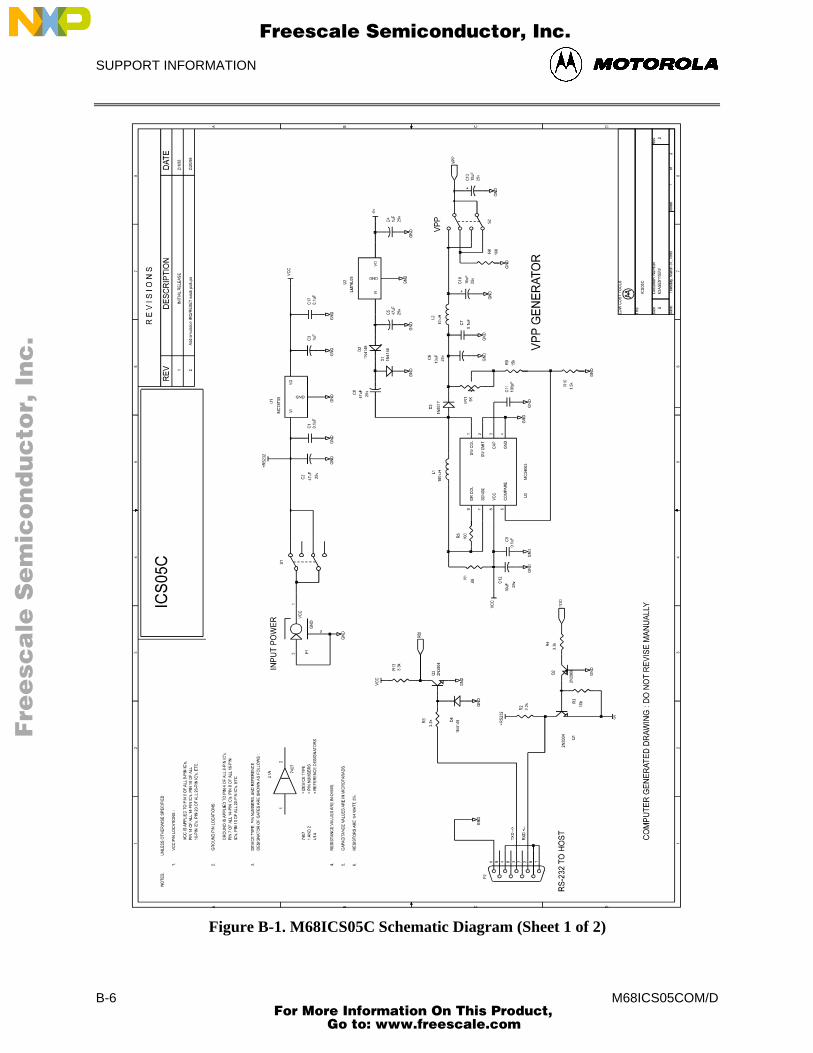
SUPPORT INFORMATION
M68ICS05COM/DB-6
Figure B-1. M68ICS05C Schematic Diagram (Sheet 1 of 2)
Fre
esc
ale
Se
mic
on
du
cto
r, I
Freescale Semiconductor, Inc.
For More Information On This Product, Go to: www.freescale.com
nc
...
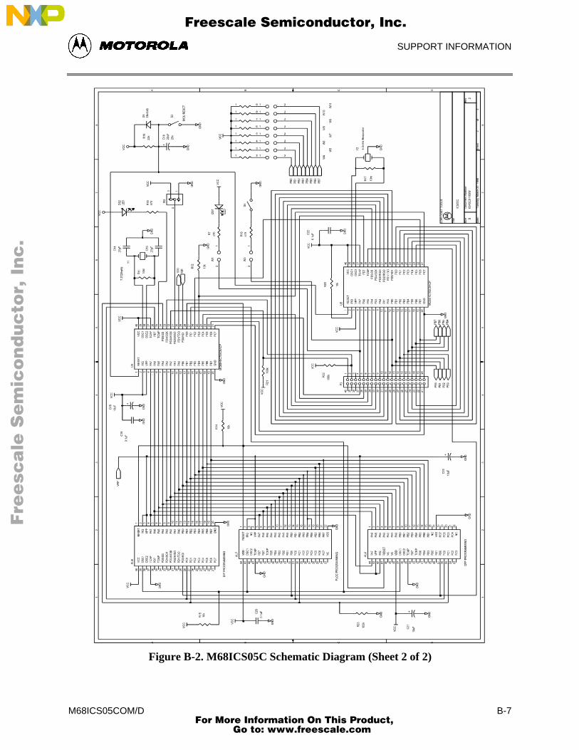
SUPPORT INFORMATION
M68ICS05COM/D B-7
Figure B-2. M68ICS05C Schematic Diagram (Sheet 2 of 2)
Fre
esc
ale
Se
mic
on
du
cto
r, I
Freescale Semiconductor, Inc.
For More Information On This Product, Go to: www.freescale.com
nc
...
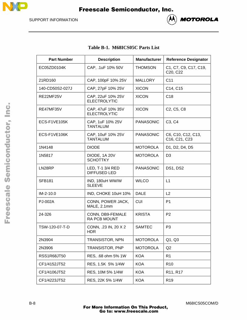
SUPPORT INFORMATION
M68ICS05COM/DB-8
Table B-1. M68ICS05C Parts List
Part Number Description Manufacturer Reference Designator
EC05ZD0104K CAP, .1uF 10% 50V THOMSON C1, C7, C9, C17, C19,C20, C22
21RD160 CAP, 100pF 10% 25V MALLORY C11
140-CD50S2-027J CAP, 27pF 10% 25V XICON C14, C15
RE22MF25V CAP, 22uF 10% 25VELECTROLYTIC
XICON C18
RE47MF35V CAP, 47uF 10% 35VELECTROLYTIC
XICON C2, C5, C8
ECS-F1VE105K CAP, 1uF 10% 25VTANTALUM
PANASONIC C3, C4
ECS-F1VE106K CAP, 10uF 10% 25VTANTALUM
PANASONIC C6, C10, C12, C13,C16, C21, C23
1N4148 DIODE MOTOROLA D1, D2, D4, D5
1N5817 DIODE, 1A 20VSCHOTTKY
MOTOROLA D3
LN28RP LED, T-1 3/4 REDDIFFUSED LED
PANASONIC DS1, DS2
SFB181 IND, 180uH WW/WSLEEVE
WILCO L1
IM-2-10.0 IND, CHOKE 10uH 10% DALE L2
PJ-002A CONN, POWER JACK,MALE, 2.1mm
CUI P1
24-326 CONN, DB9-FEMALERA PCB MOUNT
KRISTA P2
TSW-120-07-T-D CONN, .23 IN, 20 X 2HDR
SAMTEC P3
2N3904 TRANSISTOR, NPN MOTOROLA Q1, Q3
2N3906 TRANSISTOR, PNP MOTOROLA Q2
RSS1R68JT50 RES, .68 ohm 5% 1W KOA R1
CF1/4152JT52 RES, 1.5K 5% 1/4W KOA R10
CF1/4106JT52 RES, 10M 5% 1/4W KOA R11, R17
CF1/4223JT52 RES, 22K 5% 1/4W KOA R19
Fre
esc
ale
Se
mic
on
du
cto
r, I
Freescale Semiconductor, Inc.
For More Information On This Product, Go to: www.freescale.com
nc
...
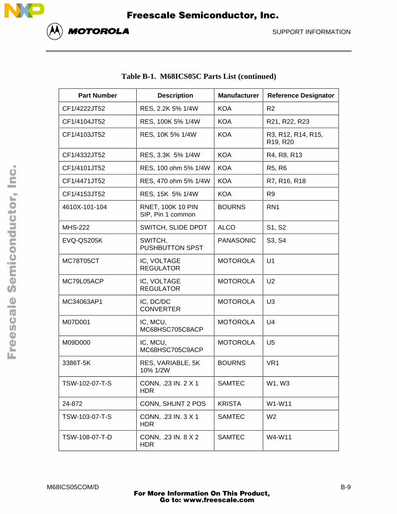
SUPPORT INFORMATION
M68ICS05COM/D B-9
Table B-1. M68ICS05C Parts List (continued)
Part Number Description Manufacturer Reference Designator
CF1/4222JT52 RES, 2.2K 5% 1/4W KOA R2
CF1/4104JT52 RES, 100K 5% 1/4W KOA R21, R22, R23
CF1/4103JT52 RES, 10K 5% 1/4W KOA R3, R12, R14, R15,R19, R20
CF1/4332JT52 RES, 3.3K 5% 1/4W KOA R4, R8, R13
CF1/4101JT52 RES, 100 ohm 5% 1/4W KOA R5, R6
CF1/4471JT52 RES, 470 ohm 5% 1/4W KOA R7, R16, R18
CF1/4153JT52 RES, 15K 5% 1/4W KOA R9
4610X-101-104 RNET, 100K 10 PINSIP, Pin 1 common
BOURNS RN1
MHS-222 SWITCH, SLIDE DPDT ALCO S1, S2
EVQ-QS205K SWITCH,PUSHBUTTON SPST
PANASONIC S3, S4
MC78T05CT IC, VOLTAGEREGULATOR
MOTOROLA U1
MC79L05ACP IC, VOLTAGEREGULATOR
MOTOROLA U2
MC34063AP1 IC, DC/DCCONVERTER
MOTOROLA U3
M07D001 IC, MCU,MC68HSC705C8ACP
MOTOROLA U4
M09D000 IC, MCU,MC68HSC705C9ACP
MOTOROLA U5
3386T-5K RES, VARIABLE, 5K10% 1/2W
BOURNS VR1
TSW-102-07-T-S CONN, .23 IN. 2 X 1HDR
SAMTEC W1, W3
24-872 CONN, SHUNT 2 POS KRISTA W1-W11
TSW-103-07-T-S CONN, .23 IN. 3 X 1HDR
SAMTEC W2
TSW-108-07-T-D CONN, .23 IN. 8 X 2HDR
SAMTEC W4-W11
Fre
esc
ale
Se
mic
on
du
cto
r, I
Freescale Semiconductor, Inc.
For More Information On This Product, Go to: www.freescale.com
nc
...
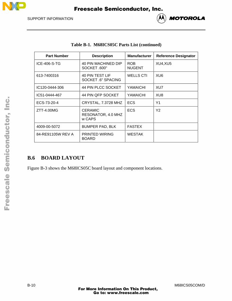
SUPPORT INFORMATION
M68ICS05COM/DB-10
Table B-1. M68ICS05C Parts List (continued)
Part Number Description Manufacturer Reference Designator
ICE-406-S-TG 40 PIN MACHINED DIPSOCKET .600"
ROBNUGENT
XU4,XU5
613-7400316 40 PIN TEST LIFSOCKET .6" SPACING
WELLS CTI XU6
IC120-0444-306 44 PIN PLCC SOCKET YAMAICHI XU7
IC51-0444-467 44 PIN QFP SOCKET YAMAICHI XU8
ECS-73-20-4 CRYSTAL, 7.3728 MHZ ECS Y1
ZTT-4.00MG CERAMICRESONATOR, 4.0 MHZw CAPS
ECS Y2
4009-00-5072 BUMPER PAD, BLK FASTEX
84-RE91105W REV A PRINTED WIRINGBOARD
WESTAK
B.6 BOARD LAYOUT
Figure B-3 shows the M68ICS05C board layout and component locations.
Fre
esc
ale
Se
mic
on
du
cto
r, I
Freescale Semiconductor, Inc.
For More Information On This Product, Go to: www.freescale.com
nc
...
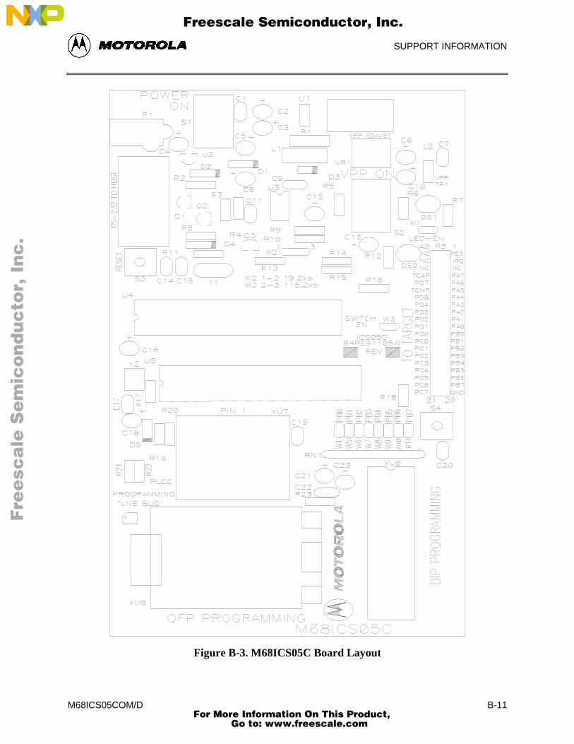
SUPPORT INFORMATION
M68ICS05COM/D B-11
Figure B-3. M68ICS05C Board Layout
Fre
esc
ale
Se
mic
on
du
cto
r, I
Freescale Semiconductor, Inc.
For More Information On This Product, Go to: www.freescale.com
nc
...
SUPPORT INFORMATION
M68ICS05COM/DB-12
Fre
esc
ale
Se
mic
on
du
cto
r, I
Freescale Semiconductor, Inc.
For More Information On This Product, Go to: www.freescale.com
nc
...
GLOSSARY
M68ICS05COM/D Glossary-1
GLOSSARY
8-bit MCU A microcontroller whose data is communicated over a data busmade up of eight separate data conductors. Members of theM68HC05 family of microcontrollers are 8-bit MCUs.
A Abbreviation for the accumulator of the M68HC05 MCU.
accumulator An 8-bit register of the M68HC05 CPU. The contents of thisregister may be used as an operand of an arithmetic or logicalinstruction.
assembler Software program that translates source code mnemonics intoopcodes that can then be loaded into the memory of amicrocontroller.
assembly language Instruction mnemonics and assembler directives that aremeaningful to programmers and can be translated into an objectcode program that a microcontroller understands. The CPU usesopcodes and binary numbers to specify the operations that make upa computer program. Humans use assembly language mnemonicsto represent instructions. Assembler directives provide additionalinformation such as the starting memory location for a program.Labels are used to indicate an address or binary value.
ASCII American Standard Code for Information Interchange. A widelyaccepted correlation between alphabetic and numeric charactersand specific 7-bit binary numbers.
breakpoint During debugging of a program, it is useful to run instructions untilthe CPU gets to a specific place in the program, and then enter adebugger program. A breakpoint is established at the desiredaddress by temporarily substituting a software interrupt (SWI)instruction for the instruction at that address. In response to theSWI, control is passed to a debugging program.
byte A set of exactly eight binary bits.
C Abbreviation for “carry/borrow” in the condition codes register ofthe M68HC05. When adding two unsigned 8-bit numbers, the C bitis set if the result is greater than 255 ($FF).
Fre
esc
ale
Se
mic
on
du
cto
r, I
Freescale Semiconductor, Inc.
For More Information On This Product, Go to: www.freescale.com
nc
...
GLOSSARY
M68ICS05COM/DGlossary-2
CCR Abbreviation for “condition codes register” in the M68HC05. TheCCR has five bits (H, I, N, Z, and C) that can be used to controlconditional branch instructions. The values of the bits in the CCRare determined by the results of previous operations. For example,after a load accumulator (LDA) instruction, Z will be set if theloaded value was $00.
clock A square wave signal that is used to sequence events in acomputer.
command set The command set of a CPU is the set of all operations that the CPUknows how to perform. One way to represent an instruction set iswith a set of shorthand mnemonics such as LDA meaning “loadA.” Another representation of an instruction set is the set ofopcodes that are recognized by the CPU.
condition codes register The CCR have five bits (H, I, N, Z, and C) that can be used tocontrol conditional branch commands. The values of the bits in theCCR are determined by the results of previous operations. Forexample, after a load accumulator (LDA) instruction, Z will be setif the loaded value was $00.
CPU Central Processor Unit. The part of a computer that controlsexecution of instructions.
CPU cycles A CPU clock cycle is one period of the internal bus-rate clock.Normally this clock is derived by dividing a crystal oscillatorsource by two or more so the high and low times will be equal. Thelength of time required to execute an instruction is measured inCPU clock cycles.
CPU registers Memory locations that are wired directly into the CPU logicinstead of being part of the addressable memory map. The CPUalways has direct access to the information in these registers. TheCPU registers in an M68HC05 are A (8-bit accumulator), X (8-bitindex register), CCR (condition codes register containing the H, I,N, Z, and C bits), SP (stack pointer), and PC (program counter).
cycles See CPU cycles
data bus A set of conductors that are used to convey binary informationfrom a CPU to a memory location or from a memory location to aCPU; in the M68HC05, the data bus is 8-bits.
Fre
esc
ale
Se
mic
on
du
cto
r, I
Freescale Semiconductor, Inc.
For More Information On This Product, Go to: www.freescale.com
nc
...
GLOSSARY
M68ICS05COM/D Glossary-3
development tools Software or hardware devices used to develop computer programsand application hardware. Examples of software development toolsinclude text editors, assemblers, debug monitors, and simulators.Examples of ha5rdware development tools include simulators,logic analyzers, and PROM programmers. An in-circuit simulatorcombines a software simulator with various hardware interfaces.
EPROM Erasable, Programmable Read-Only Memory. A non-volatile typeof memory that can be erased by exposure to an ultra-violet lightsource. MCUs that have EPROM are easily recognized by theirpackaging: a quartz window allows exposure to UV light. If anEPROM MCU is packaged in an opaque plastic package, it istermed a “one-time-programmable” OTP MCU, since there is noway to erase and rewrite the EPROM.
H Abbreviation for “half-carry” in the condition codes register of theM68HC05. This bit indicates a carry from the low-order four bitsof an 8-bit value to the high-order four bits. This status indicator isused during BCD calculations.
I Abbreviation for “interrupt mask bit” in the condition codesregister of the M68HC05.
index register An 8-bit CPU register in the M68HC05 that is used in indexedaddressing mode. The index register (X) can also be used as ageneral purpose 8-bit register (in addition to the 8-bit accumulator).
input-output (I/O) Interfaces between a computer system and the external world: forexample, a CPU reads an input to sense the level of an externalsignal and writes to an output to change the level on an externalsignal.
instructions Instructions are operations that a CPU can perform. Instructions areexpressed by programmers as assembly language mnemonics. ACPU interprets an opcode and its associated operand(s) as aninstruction.
listing A program listing shows the binary numbers that the CPU needsalongside the assembly language statements that the programmerwrote. The listing is generated by an assembler in the process oftranslating assembly language source statements into the binaryinformation that the CPU needs.
MCU Microcontroller: a complete computer system including CPU,memory, clock oscillator, and I/O on a single integrated circuit.
Fre
esc
ale
Se
mic
on
du
cto
r, I
Freescale Semiconductor, Inc.
For More Information On This Product, Go to: www.freescale.com
nc
...
GLOSSARY
M68ICS05COM/DGlossary-4
memory location In the M68HC05, each memory location holds one byte of data andhas a unique address. To store information into a memory locationthe CPU places the address of the location on the address bus, thedata information on the data bus, and asserts the write signal. Toread information from a memory location the CPU places theaddress of the location on the address bus and asserts the readsignal. In response to the read signal, the selected memory locationplaces its data onto the data bus.
N Abbreviation for “negative,” a bit in the condition codes register ofthe M68HC05. In twos-complement computer notation, positivesigned numbers have a zero in their MSB and a negative numbershave a one in their MSB. The N condition code bit reflects the signof the result of an operation. After a load accumulator instruction,the N bit will be set if the MSB of the loaded value was a one.
object code file A text file containing numbers that represent the binary opcodesand data of a computer program. An object code file can be used toload binary information into a computer system. Motorola uses theS-record file format for object code files.
operand An input value to a logical or mathematical operation.
opcode A binary code that instructs the CPU to do a specific operation in aspecific way. The M68HC05 CPU recognizes 210 unique 8-bitopcodes that represent addressing mode variations of 62 basicinstructions.
OTPROM A non-volatile type of memory that can be programmed but cannotbe erased. An OTPROM is an EPROM MCU that is packaged inan opaque plastic package, it is called a “one-time-programmable”MCU because there is no way to expose the EPROM to a UV light.
PC Abbreviation for program counter CPU register of the M68HC05.
program counter The CPU register that holds the address of the next instruction oroperand that the CPU will use.
RAM Random Access Memory. Any RAM location can be read orwritten by the CPU. The contents of a RAM memory locationremain valid until the CPU writes a different value or until poweris turned off.
Fre
esc
ale
Se
mic
on
du
cto
r, I
Freescale Semiconductor, Inc.
For More Information On This Product, Go to: www.freescale.com
nc
...
GLOSSARY
M68ICS05COM/D Glossary-5
registers Memory locations that are wired directly into the CPU logicinstead of being part of the addressable memory map. The CPUalways has direct access to the information in these registers. TheCPU registers in the M68HC05 are A (8-bit accumulator), X (8-bitindex register), CCR (condition codes register containing the H, I,N, Z, and C bits), SP (stack pointer), and PC (program counter).Memory locations that hold status and control information for on-chip peripherals are called I/O and control registers.
reset Reset is used to force a computer system to a known starting pointand to force on-chip peripherals to known starting conditions.
S-record A Motorola standard format used for object code files.
simulator A computer program that copies the behavior of a real MCU.
source code See source program
SP Abbreviation for stack pointer CPU register in the M68HC05MCU.
source program A text file containing instruction mnemonics, labels, comments,and assembler directives. The source file is processed by anassembler to produce a composite listing and an object filerepresentation of the program.
stack pointer A CPU register that holds the address of the next available storagelocation on the stack.
VDD The positive power supply to a microcontroller (typically 5 voltsdc).
VSS The 0 volt dc power supply return for a microcontroller.
Word A group of binary bits. Some larger computers consider a set of 16bits to be a work but this is not a universal standard.
X Abbreviation for “index register,” a CPU register in the M68HC05.
Z Abbreviation for “zero,” a bit in the condition codes register of theM68HC05. A compare instruction subtracts the contents of thetested value from a register. If the values were equal, the result ofthis subtraction would be zero so the Z bit would be set; after aload accumulator instruction, the Z bit will be set if the loadedvalue was $00.
Fre
esc
ale
Se
mic
on
du
cto
r, I
Freescale Semiconductor, Inc.
For More Information On This Product, Go to: www.freescale.com
nc
...

GLOSSARY
M68ICS05COM/DGlossary-6
Fre
esc
ale
Se
mic
on
du
cto
r, I
Freescale Semiconductor, Inc.
For More Information On This Product, Go to: www.freescale.com
nc
...
INDEX
M68ICS05COM/D Index-1
INDEX
%%FILE%, 4-6, 4-7, 4-20, 4-25, 4-27, 8-2
..ASM files, 3-2
AA command, 7-10ACC command, 7-10Accumulator value, 6-22adding
breakpoints, 6-21variables, 6-10
address, 5-14fields in listing file, 6-4
ASCIIcharacters, A-6constants, 5-8files, 3-2, 6-4format, 6-12
ASM command, 7-11assembler
comments, 5-8conditional assembly, 5-11constants, 5-7description, 1-1, 1-2directives, 5-6, 5-8, 5-9, 5-11, 5-12, 5-20error messages, 5-18files, 3-2, 3-3interface, 5-1listing directives, 5-13listing files
fields, 5-14operands, 5-7options, 4-17speed of assembled code, 6-2third party, 5-6, 5-20
Assembler/Compilerconditional assembly, 5-11file button, 5-1files, 3-2interface, 5-1options, 1-5, 4-17outputs, 5-5parameters, 5-4preferences, 4-24progress window, 4-24quick start, 1-6
tab, 4-22Auto-Indentation, 4-21Auto-Save All Files, 4-20Auto-Save Current Project, 4-19
BBack to Editor toolbar button, 4-5base address
setting, 6-8batch files
error output, 4-26EXE path, 4-22
BELL command, 7-12, 7-13BF command, 7-13board layout, B-10board repair, B-5BR command, 7-14branching, 5-14Breakpoint Window, 6-21breakpoints, 1-2
adding, 6-21counting, 6-22deleting, 6-22editing, 6-22removing, 6-22setting, 6-8
BREAKSP command, 7-18BREAKX command, 7-20Browse, 3-2bus rate, B-2
CC command, 7-22C8 device, B-1CAPTURE command, 7-23CAPTUREFILE command, 7-24CASM05W
assembler comments, 5-8assembler directives, 5-8assembler options, 5-7, 8-2assembler parameters, 5-4command-line parameters, 5-3, 5-4conditional assembly, 5-11cross-assembler, 3-1cycle adder, 5-9description, 1-1, 1-3, 3-1environment, 1-5, 8-2error messages, 5-18files, 3-3INCLUDE directive, 5-11
Fre
esc
ale
Se
mic
on
du
cto
r, I
Freescale Semiconductor, Inc.
For More Information On This Product, Go to: www.freescale.com
nc
...
INDEX
M68ICS05COM/DIndex-2
MACRO directive, 5-12macros, 5-12object files, 6-3outputs, 3-1, 5-5pseudo-operations, 5-16quick-start, 1-6sample project, 8-1shortcut, 5-3substituting, 3-1, 5-6, 5-20user interface, 5-2window, 1-6, 5-2, 5-4
CC value, 5-14CCR command, 7-25CF command, 7-24changes
bases, 6-11CPU information, 6-15restoring, 4-15reverses, 4-14save options, 4-19saving, 4-13software startup, 6-5
checksum, A-1child windows, 4-2chip logic,representing, 6-17Chip Window, 6-17CHIPINFO, 1-2clearing
Clear All, 6-11markers, 4-6variables, 6-11
CLEARMAP command, 7-27CLEARSYMBOL command, 7-28client windows
WinIDE, 4-2clock signal, B-2closing files
current project file, 4-18WinIDE, 4-13
code timing, 6-18Code Window, 6-7, 6-8, 7-87code/data, A-1Color, 4-29column numbers, 4-3command
buffer, 6-25sequences, 1-2syntax, 7-2
command-lineentering commands, 6-13parameters, 4-6
comments, 5-8communications, pod-to-host, 1-2, 3-3Compact, 3-3compiler
customized, 3-2options, 4-17third party, 6-3types, 4-23
componentsICS05CW, 1-1
conditional assembly, 5-11configuring external programs in WinIDE, 4-22Confirm command line, 4-25, 4-28context-sensitive Help, 1-2copying text, 4-15counting
breakpoints, 6-22cycles, 6-18
CPUregisters, 6-15results, 6-18Window, 6-15
Create Backup, 4-21creating
new fileWinIDE, 4-11
script files, 6-4source files, 4-14
Currently edited filename, 4-20customizing environments, 1-6cycles
adding, 5-9counter, 5-14counting, 6-18Cycle Adder, 5-9Cycle Cntr, 5-14CYCLES command, 7-30Cycles Window, 6-18field in listing file, 6-4including information in list file, 4-24
CYCLES command, 7-30
DDASM command, 7-31DDRA command, 7-32DDRB command, 7-33debugger
customized, 3-2options, 4-17routines, 6-33third-party, 4-22
debugging commandscommand set, 7-1description, 7-1detailed listing, 7-9entering, 6-25summary, 7-3, 7-4syntax, 7-2
deletingbreakpoint, 6-22text, 4-16variables, 6-11
desktop information, 4-17direct addressing mode, 5-17Direction, 4-30displaying
Fre
esc
ale
Se
mic
on
du
cto
r, I
Freescale Semiconductor, Inc.
For More Information On This Product, Go to: www.freescale.com
nc
...
INDEX
M68ICS05COM/D Index-3
Code Window Shortcut menu, 6-8source code, 6-7Stack Window:, 6-18Trace Window, 6-20Variables Shortcut menu, 6-10
distribution media, 3-2download files, 6-24drive space, 1-2DUMP command, 7-34
Eediting
breakpoints, 6-22options, WinIDE, 4-14, 4-20source files, 4-14text, 3-1
editordescription, 1-2, 3-1files, saving, 4-20options, 4-20options, WinIDE, 4-14
Effects, 4-29emulator, B-1environment
building, 4-3customizing, 1-6Environment Menu, 1-4, 4-17Environment Settings Dialog, 1-4options, 4-16path, 4-22settings, 4-16, 4-17storing settings, 4-16
EPROM, 1-1, 1-2EQU, 5-16equate directive, 5-16errors
files, 4-26, 6-3format, 4-26messages,assembler, 5-18output batch file, 4-26
EVAL command, 7-35examples
changing number format, 6-11conditional assembly directives, 5-11labels, 5-15listing table, 5-15macro directive, 5-12S-records, A-3
EXE 1 (Debugger) tab, 4-26EXE 2 (Programmer) tab, 4-26EXE Path, 4-27executable options, 4-17executing
source code, 6-8Exit Application, 4-20EXIT command, 7-36exiting
application, 4-20
WinIDE, 4-11, 4-14Expand Includes in List, 4-24Expand Macros in Listing, 4-24extended addressing mode, 5-17extension
specifying, 4-6External Program 1 toolbar button, 4-5external programs, 4-26
configuring in WinIDE, 4-22running, 4-22
external pull-down resistors, B-2
FFCB directive, 5-17FDB directive, 5-17fields
listing files, 6-4file options
ICS, 6-28WinIDE, 4-11
filenamestoring as parameter, 4-19
filename parameter, 4-6files
ASCII, 3-2, 6-4assembler, 3-3assembly, 3-2ICS, 3-3ICS05CW, 3-3listing, 8-4map, 3-2object code, 3-2printing, 4-13programmer download, 6-24programmer upload, 6-24S19, 3-2, 6-3saving, 4-12, 4-20script, 6-4startup, 6-6WinIDE, 3-3
filetypesWinIDE, 4-4
Find DialogWinIDE, 4-29
Find Next button, 4-30Find what textbox, 4-30Fixed Tabs, 4-22Font, 4-28font settings, 4-16Font Style, 4-28Form Constant Byte, 5-17Form Double Byte, 5-17
GG command, 7-37General Editor, 1-5General Editor options, 4-17
Fre
esc
ale
Se
mic
on
du
cto
r, I
Freescale Semiconductor, Inc.
For More Information On This Product, Go to: www.freescale.com
nc
...
INDEX
M68ICS05COM/DIndex-4
General Editor Tab, 4-20, 4-21General Environment, 1-5General Environment options, 4-17General Environment Tab, 4-19General Options, 4-21Give user option to save each file, 4-20GO command, 7-37GOMACRO command, 7-38Gotil Address at Cursor, 6-8GOTIL command, 7-39GOTOCYCLE command, 7-40
HH command, 7-41hardware
installation, 2-1requirements, 1-2specifications, 1-3
Help, 1-2HELP command, 7-42HEX format, 6-12hexadecimal number format, 6-10hexadecimal values
field in listing file, 6-4humidity, 1-3
II command, 7-43I/O, 1-1I/O pins, 6-17ICS, 6-1
Execute Menu, 6-33Execute Options, 6-33File Menu, 6-28File options, 6-28files, 3-3menu options
Close Logfile, 6-32Exit, 6-32Go, 6-34Load S19 File, 6-29Multiple Step, 6-34Open Logfile, 6-31Open Window, 6-35Play Macro, 6-30Record Macro, 6-30Reload Desktop, 6-36Reload Last S19, 6-29Reset Processors, 6-33Save Desktop, 6-36Stop, 6-34Stop Macro, 6-31
starting, 6-5Window Options, 6-35windows
Breakpoint Window, 6-21Chip Window, 6-17
Code Windows, 6-7CPU Window, 6-15CPU Wndow, 6-15Cycles Window, 6-18Memory, 6-12Memory Window, 6-12Personality EEPROM Window, 6-20Programmer Window, 6-23Stack Window, 6-18, 6-19Status Window, 6-13Trace Window, 6-20Variables Window, 6-9, 6-10
ICS05CW, 3-2ICS05CW, 1-1, 1-2, 1-4, 1-6
Components, 1-1features, 1-2
ICS05CW command argument types, 7-3ICS05CW command overview, 7-4, 7-5, 7-6, 7-7, 7-8, 7-9ICS05CW command set, 7-1ICS05CW COMMAND SYNTAX, 7-2ICS05CW commands, 6-13ICS05CW simulation speed, 6-1If Modified files exist just prior to external program
execution:, 4-20In-Circuit Simulator, 1-1
user interface, 6-1INCLUDE, 8-3INCLUDE directive, 5-11included files
expanding, 4-24using, 4-20
indentation, 4-20INFO command, 7-44initialization sequence, B-2INPUTA command, 7-45INPUTB command, 7-46INPUTS command, 7-47installation
compact, 3-3typical, 3-3
installingICS05CW software, 3-2M68HC705J1A pod, 2-1M68ICS05C pod, 2-1software, 3-1, 3-2
INT command, 7-48integrated development environment, 1-1internal charge pump, B-2internal registers, 6-15Interrupt Stack, 6-19IRQ command, 7-48
Jjumper headers, B-2
Llabels, 5-12, 5-14, 5-15, 6-10
Fre
esc
ale
Se
mic
on
du
cto
r, I
Freescale Semiconductor, Inc.
For More Information On This Product, Go to: www.freescale.com
nc
...
INDEX
M68ICS05COM/D Index-5
LF command, 6-5line count, 5-14
field in list file, 6-4line numbers, 4-3lines
total, 4-3listing directives, 5-13listing files, 4-4, 4-24, 5-6, 5-13, 6-4
fields, 5-14Listing Options, 4-24listing table, 5-14LISTOFF command, 7-49LISTON command, 7-50LOAD command, 7-51Load S19 File, 6-29LOADDESK command, 7-52loading
map files, 6-29LOADMAP command, 7-53Log Files, 6-5
opening, 6-31specifying, 6-31
LOGFILE command, 6-5
MM68HC05 MCUs, 6-19M68HC705C, 1-1, 1-2M68ICS05C, 1-1, 1-2, 1-3, 1-4, 2-1, 4-4, 6-1, 6-23, 7-67,
B-1, B-2board layout, B-10board repair, B-5features, 1-2parts list, B-8, B-9, B-10pod, 4-4schematic diagram, B-5, B-6, B-7support information, B-1
machine cycles, 5-14MACRO command, 7-55MACRO directive, 5-12MACROEND command, 7-56macros
expanding, 4-24forward referencing, 5-13jumping from, 5-13recording, 6-30running, 6-30stopping, 6-31
MACROSTART command, 7-57Main Filename, 4-20Main Filename option
WinIDE, 4-25managing
Code Window contents, 6-8open windows, 4-31project information, 4-16variables, 6-10WinIDE files, 4-11
map files, 3-2, 5-6
loading, 6-29Marker Sub-menu, 4-6markers
clearing, 4-6moving, 4-5, 4-6setting, 4-5, 4-6using, 4-5
Match Case, 4-30, 4-31Match Whole Word Only, 4-30MC68HC705C8 device, B-1MCUs, 1-1MD command, 7-58media, 3-2memory, 1-2
address, 5-14, A-1map, 1-2, 6-12modifying, 6-12viewing, 6-12
Memory Window, 6-12Shortcut menu, 6-12
menu optionsWinIDE, 4-9, 4-10, 6-27, 6-28
menusWinIDE, 4-9
microcontrollers, 1-1MM command, 6-12, 7-59modifying
memory, 6-12memory bytes, 6-12
Motorola Board Repair, B-5
NN command, 7-60navigating
in IDE environment, 4-5in sour files, 4-5
No Trace Available, 6-20NOBR command, 7-61NOMAP command, 7-62non-P&E compiler, 4-23NOSYMBOL command, 7-62number format, 6-10
Oobject files, 3-2, 5-5opcode mnemonics, 5-7Open File dialog
WinIDE, 4-12Open Logfile, 6-31Open Project, 1-4opening
log files, 6-31WinIDE files, 4-12
operating system, 1-2Options, 4-27ORG, 5-17originate directive, 5-17
Fre
esc
ale
Se
mic
on
du
cto
r, I
Freescale Semiconductor, Inc.
For More Information On This Product, Go to: www.freescale.com
nc
...
INDEX
M68ICS05COM/DIndex-6
Other Assembler/Compiler, 4-25Output Debug File, 4-23Output Listing File, 4-23Output S19 Object, 4-23
PP&E compiler, 4-23P1, 2-1P2, 1-4, 2-1parameters
command-line, 4-6parts list, B-8, B-9, B-10pasting text, 4-16path, EXE, 4-22PC command, 7-63Pick Window, 6-23PIF files, 4-22pin-out, 1-2pins, 6-17Play Macro, 6-30pod, 1-1, 1-2, 1-4, 6-17
communications, 3-3connector P2, 1-4installation, 2-1
POD command, 7-64PORTA command, 7-65PORTB command, 7-66ports
data, B-1serial, 1-2
powerrequirements, 1-3supply,connecting, 1-4switch, 2-1
PPF files, 4-17printing, 4-11, 4-13processor cycles
viewing number, 6-18PROG05P3 Programmer Pick Window, 6-23program counter
setting, 6-8Program Manager, 3-3Programmer Files Window, 6-24Programmer Status Window, 6-23Programmer Window, 6-23programming C devices
control, B-2equipment, 4-22troubleshooting, B-4voltage, B-2
projectenvironment, 4-3, 4-16files, 4-17name, 4-16sample, 8-1saving, 4-18
Project Files, 6-2PRTA command, 7-65
PRTB command, 7-66pseudo operations, 5-16
Qquick start, 1-4Quick Start troubleshooting, B-2QUIT command, 7-36
RR command, 7-70RAM, 1-2Real Tabs, 4-22record length, A-1Record Macro, 6-30record type, A-1recording macros, 6-30Recover Error from Compiler, 4-25Redo
WinIDE, 4-15REG command, 7-71registers, 1-2Reload Last S19, 6-29REM command, 7-72removing
breakpoints, 6-22Replace Dialog, 4-30requirements
hardware, 1-2host, 6-2host computer, 1-2software, 1-2
Reserve Memory Byte, 5-17reset
microcontroller, 6-33switch, 2-1
RESET command, 7-73RESETGO command, 7-74reversing changes, 4-14RMB directive, 5-17RS-232 serial connector, 2-1RTI, 6-18RTS, 6-18Run, 3-2RUN command, 7-37running
macros, 6-30
SS1, 2-1S19 files, 3-2, 6-3S3, 2-1Sample, 4-29sample project, 8-1Save all files before running, 4-28Save files before Assembling, 4-24, 4-25
Fre
esc
ale
Se
mic
on
du
cto
r, I
Freescale Semiconductor, Inc.
For More Information On This Product, Go to: www.freescale.com
nc
...
INDEX
M68ICS05COM/D Index-7
SAVEDESK command, 7-75saving
changing options, 4-19files, 4-12projects, 4-18
Saving the Project, 4-20schematic diagram, B-5, B-6, B-7scratch pad files, 6-5SCRIPT, 1-2, 4-29Script Files, 6-4Search Menu
WinIDE, 4-29Select Source Module, 6-9selecting text, 4-16serial port
connector, 1-4, 2-1use, 1-2
Set Base Address, 6-8, 6-12Set Base Address to PC, 6-9Set PC at Cursor, 6-8setting
base address, 6-8breakpoints, 6-8markers, 4-5, 4-6program counter, 6-8
setup, 3-2ICS05CW software, 1-4
Setup Environment option, 1-4Setup Fonts Dialog, 4-28Show as HEX and ASCII, 6-12Show as HEX Only, 6-12Show Assembler Progress, 4-24Show Cycles in Listing, 4-24Show Disassembly, 6-9Show Source/Disassembly, 6-9SHOWBREAKS command, 6-21, 7-76SHOWCODE command, 7-77SHOWTRACE command, 6-20, 7-79simulation
mode,ICS05CW, 4-4speed, 6-1
simulator, 1-2, 4-22Size, 4-28SLD map files, 6-29Smart Tabs, 4-22software
installation, 3-2loading, 3-1modifying startup, 6-5requirements, 1-2starting, 3-3WinIDE, 1-1
Sound Bell on Error, 4-24source code, 5-14
assembly mode, 6-8disassembly mode, 6-8editing, 3-1executing, 6-8files, 4-4
source filescreating, 4-14editing, 4-14preparing, 5-6
source windowWinIDE, 4-3
source-level debugging, 5-6SP command, 7-81specifications
hardware, 1-3Specify project file to save Dialog, 4-18specifying
ASCII constants, 5-8speed
calculating, 6-2simulation, 6-1
Split Bar, 4-36Split Pointer, 4-36S-records
content, A-1creating, A-3field contents, A-2fields, A-1overview, A-1S0 header record, A-4S0 record, A-4S1 record, A-5S9 record, A-6termination record, A-6types, A-2
SS command, 7-82STACK command, 7-84stack data interpretations, 6-19stack pointer value, 6-18, 6-22stack values
viewing, 6-18Stack Window, 6-18, 6-19
displaying, 6-18standalone mode, 6-5Start Menu, 3-2, 3-3starting
ICS, 6-5ICS05CW, 1-4software, 3-3WinIDE, 4-4
startup files, 6-6STARTUP.05P, 6-6status bar
WinIDE, 4-3Status Window, 6-13
command-line area, 6-13message area, 6-13
STEP command, 7-83STEPFOR command, 7-85STEPTIL command, 7-86Stop Macro, 6-31storing
desktop information, 4-17environment settings, 4-16
Fre
esc
ale
Se
mic
on
du
cto
r, I
Freescale Semiconductor, Inc.
For More Information On This Product, Go to: www.freescale.com
nc
...
INDEX
M68ICS05COM/DIndex-8
executable options, 4-17Strikeout, 4-29Subroutine Stack, 6-19switches
compiler/assembler, 4-25DIP, 1-1power, 2-1reset, 2-1
SYMBOL command, 6-10, 7-87symbol table, 5-15
list file, 6-4system
progress, 4-3requirements, 6-2status, 4-3
Ttab settings, 4-20, 4-22Tab Size, 4-22temperature
operating, 1-3storage, 1-3
text files, 4-4timing code, 6-18title bar
WinIDE, 4-3Toggle Breakpoint at Cursor, 6-8toolbar
WinIDE, 4-7, 6-25TRACE command, 6-20, 7-88Trace Window, 6-20
displaying, 6-20tracing
trace buffer, 6-20trace buffer slot numbers, 6-20viewing, 6-20
transformerconnecting, 1-4
troubleshootingprogrammer, B-4Quick Start, B-2
TYPE, 4-23, 4-27Typical, 3-3
UU2, 6-23Underline, 4-29Understanding Small Microcontrollers, 1-2Undo
WinIDE, 4-14upload files, 6-24UPLOAD_SREC command, 7-89Upon Exiting WinIDE, 4-19user interface
ICS, 6-1WinIDE, 4-1
user manual, 1-2
Vvalues on stack, 6-18VAR command, 7-90variables
adding, 6-10choosing types, 6-11clearing, 6-11deleting, 6-11managing, 6-10
Variables Window, 6-9, 7-87Shortcut menu options, 6-10
vector, 1-2VERSION command, 7-91viewing
breakpoints, 6-21command results, 6-13CPU information, 6-15instructions during tracing, 6-20memory, 6-12
WWAIT command, 7-92Wait for Assembler Result, 4-24Wait for compiler to finish, 4-25Wait for program completion, 4-28WHEREIS command, 7-93Window Base Address dialog, 6-8windows
CASM05W, 8-4ICS, 6-7WinIDE, 4-1
Windows 3.x, 1-1, 1-2, 3-3Windows 95, 1-1, 1-2, 1-4, 3-3WinIDE, 1-1
Assembler/Compiler Tab, 4-22closing files, 4-13configuration parameters, 4-17configuring external programs, 4-22Edit menu, 4-14Edit options, 4-14
Close/New Project, 4-18Copy, 4-15Cut, 4-15Delete, 4-16Open Project, 4-17Paste, 4-16Redo, 4-15Save Project, 4-18Save Project As, 4-18Select All, 4-16Setup Environment, 4-18Undo, 4-14
Edit shortcut menu, 4-5Environment Menu, 4-17Environment options, 4-16
Setup Fonts, 4-28Environment Settings Dialog, 1-5
Fre
esc
ale
Se
mic
on
du
cto
r, I
Freescale Semiconductor, Inc.
For More Information On This Product, Go to: www.freescale.com
nc
...
INDEX
M68ICS05COM/D Index-9
Environment Settings dialogEXE1 Tab, 1-5
exiting, 4-14file management, 4-11file options, 4-11
Close File, 4-13Exit, 4-14New File, 4-11Open File, 4-12Print, 4-13Print Setup, 4-14Save File, 4-12Save File As, 4-12
files, 3-3filetypes, 4-4
listing, 4-4source code, 4-4text, 4-4
font information, 4-16General Environment Tab, 4-19INI file, 1-5, 4-16main window, 4-2menu options, 4-1, 4-9, 4-10, 6-27, 6-28menus, 4-9printing, 4-11saving files, 4-12Search options, 4-29
Find, 4-29Find Next, 4-31Go to Line, 4-31
shortcut buttons, 4-7, 6-25source directory, 4-16source window, 4-3starting, 4-4status bar, 4-3title bar, 4-3toolbar, 4-7, 6-25user interface, 4-1window components, 4-2Window Menu, 4-32Window options, 4-31
Arrange Icons, 4-34Cascade, 4-32Minimize All, 4-35Split, 4-36Tile, 4-33
windows, 4-1WINIDE.INI file, 1-5, 4-16word wrap, 4-20, 4-21Word Wrap OFF, 4-22Wrap to Column, 4-21Wrap to Window, 4-21
XX command, 7-94X index register value, 6-22XREG command, 7-94
ZZ command, 7-95
Fre
esc
ale
Se
mic
on
du
cto
r, I
Freescale Semiconductor, Inc.
For More Information On This Product, Go to: www.freescale.com
nc
...
INDEX
M68ICS05COM/DIndex-10
Fre
esc
ale
Se
mic
on
du
cto
r, I
Freescale Semiconductor, Inc.
For More Information On This Product, Go to: www.freescale.com
nc
...