ci10949-l keep track of the vehicles using vehicle...
TRANSCRIPT
CI10949-L
Keep Track of the Vehicles Using Vehicle Tracking Vincent Sheehan Timmons Group Learning Objectives
Create parking lots.
Sweep vehicles through a site.
Create roundabout junction corridors.
Print and export reports.
Change object styles.
Description In this lecture, you’ll learn how to generate parking lots, sweep vehicles around a site and create a roundabout junction corridor. Step-by-step, you’ll learn how to choose a parking lot style that is right for your site. Select the appropriate vehicle to check for turning movements and height clearances. Create a roundabout junction corridor to add to an existing Civil 3D® road corridor. You’ll also generate reports, customize the settings and standards to for a specific project.
Your AU Experts
Vince has been using Autodesk® products since 1992. He has been working in the GIS, Civil Engineering and Surveying field since 1995. He currently serves as Sr. Designer for Timmons Group, a civil engineering consulting firm located in Richmond, Virginia. He is also a Design Specialist and Blogger on the site Poly In 3D where he writes tutorials and how to tips for Autodesk® products and a lab presenter at Autodesk University 2012. Vince has also been 3D modeling and rendering for over 10 years using a verity of Autodesk® products and other non Autodesk® products.
http://polyin3d.blogspot.com
Keep Track of Vehicles using Vehicle Tracking
2
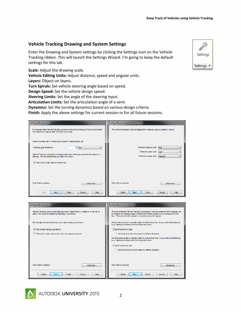
Vehicle Tracking Drawing and System Settings
Enter the Drawing and System settings by clicking the Settings icon on the Vehicle Tracking ribbon. This will launch the Settings Wizard. I’m going to keep the default settings for this lab.
Scale: Adjust the drawing scale. Vehicle Editing Units: Adjust distance, speed and angular units. Layers: Object on layers. Turn Spirals: Set vehicle steering angle based on speed. Design Speed: Set the vehicle design speed. Steering Limits: Set the angle of the steering input. Articulation Limits: Set the articulation angle of a semi. Dynamics: Set the turning dynamics based on various design criteria. Finish: Apply the above settings for current session or for all future sessions.

Keep Track of Vehicles using Vehicle Tracking
3
Parking Design
1. Open Parking Design - 01.dwg drawing in the project folder. 2. Click the Vehicle Tracking tab on the Ribbon. 3. Click the New Row button. This will launch the Parking Standard Explorer. 4. Select the US Parking Standards, ITE Guideline for Parking Facility Location and Design
Parking Standard design guide. (The parking standards can be modified to suit your design or company standards.)
5. Click ok on the Name. 6. Click ok on the scale and surface settings. 7. In the Parking Row Properties dialog box, select the aligned icon (second icon) under Bay
aligned. The design calls for: a. Two Way b. Small cars c. 90 degrees
8. Snap to the end point of the magenta guide line. 9. Drag and snap the parking row to the other end of the magenta guide line. 10. Right click to exit command and right click again to place bays on both sides.

Keep Track of Vehicles using Vehicle Tracking
4
Create Parallel Parking Rows
1. To place additional bays, click the lower half of the new Row button on the ribbon. 2. Click Parallel Row. 3. Select the parking row. 4. Slide the new parking row to the west or left and close as possible to the first row then click
to place the new row. 5. Right click to place bays on both sides. The red arrow(s) allows for placement of stalls on either
or both sides of the row. 6. Repeat steps 2-5 to place additional rows.
At each the end of the parking lot, we only need parking stalls on one side of the row.
7. Repeat the last command to place an additional row. 8. Place the row then left click to the inside of the parking lot. 9. Repeat steps 7 & 8 for the other side of parking.
Run Parking Report
1. Click Parking Report on the Parking panel on the ribbon. 2. The report can be exported to CSV, HTML and TXT file formats. 3. Leave the Parking Bay Report open.

Keep Track of Vehicles using Vehicle Tracking
5
Modifying the Parking Rows
The row geometry can be modified either by grips or buttons on the Parking panel on the ribbon.
1. Click on a parking row. 2. Adjust the parking row with the following grips.
a. Add Vertex (Plus) b. Adjust Vertex (Outer Box) c. Adjust Vertex Curve (Arrow) ► d. Insert Vertex (Plus)
e. Extend Row (Arrow) f. Adjust Island Angle Both Sides (Inner Diamond) ♦
g. Adjust Island Angle This Side (Outer Diamond) ♦
h. Adjust Bay Angle (Near Bay Diamond) ♦ i. Change Direction (Middle of Row Box) j. Move Row (Inner Box)
k. Join Parking Row. 3. Click the Extend Vertex grip. 4. Drag to the yellow edge of pavement. (Note the parking report updating.) 5. Repeat steps 1 – 4 to adjust the other rows.
Modifying the Parking Bays
1. Click the Edit Parking Bay button on the ribbon. 2. Select a parking row. 3. Blue boxes will appear. 4. Pick the stall. A red box will appear in the stall. 5. Click the edit Bay Type button. 6. Add bay symbols, markings or other items. 7. Select Disabled from the Bay Type pull down at the top. (This will add the
handicap symbol and striping to the parking bay.) 8. Click the Copy To button then select additional bays. 9. Right click or Esc to exit the command.
Modifying the Parking Islands
1. Click the Edit Parking Island button on the ribbon. 2. Select a parking island. A red box will appear at the end of the island 3. Pick near the red box. 4. Check the Custom non-standard properties box. 5. Adjust the Bay side curb return to 1. 6. Adjust the Outer curb returns to 5. 7. Adjust the Minimum internal width to 1. 8. Uncheck Allow width to increase. 9. Adjust Minimum width at curb to 10. 10. Uncheck the Hatch box. 11. Click OK.

Keep Track of Vehicles using Vehicle Tracking
6
Creating an Access Road
There are two ways of creating an access road.
Create an access road from a polyline or Civil 3D alignment.
1. Click the Create Access Road from Line button in the parking panel on the
ribbon. 2. Select the white center line through the parking lot. 3. Leave setting with default values except for Custom Width. 4. Check the box then adjust the width to 30. 5. Click OK.
Create an access road from two base points.
1. Click the Create Access Road button in the parking panel on the ribbon. 2. Pick the first point point on one side of the parking lot then pick the second point on the other
side of the parking lot. 3. Leave setting with default values except for Custom Width. 4. Check the box then adjust the width to 30. 5. Click OK.
Swept Paths
1. Open Vehicle Turning Movement - 01.dwg in the project folder. 2. Click the Vehicle Tracking tab on the Ribbon. 3. Click the Auto Drive Arc button on the Swept Paths panel on the ribbon. This will launch
the Vehicle Library Explorer and Vehicle Diagram. 4. Select the US Design Vehicles, State-wide (AASHTO), AASHTO 2011 (US Customary) and
WB-40 – Intermediate Semi-Trailer Tractor. 5. Click the Vehicle Diagram button to see information about the vehicle. 6. Close the Vehicle Diagram and click Proceed to close the Vehicle Library
Explorer. 7. Click to position the vehicle in the entrance travel lane of the site. 8. Rotate the vehicle in a travel direction. 9. The vehicle orientation and drawing views can be adjusted in the
Position Vehicle dialog box. 10. Click the Proceed button. 11. Move the cursor down the travel lane then click a point in the travel
lane. 12. To make a right turn, click the Pick Alignment… button on the AutoDrive
dialog box. 13. Select a datum object such as the edge of pavement line. 14. Continue to drive the vehicle around the site. 15. To reverse the vehicle, move the cursor towards the rear of the vehicle. 16. Right click or Esc to exit the command.
Keep Track of Vehicles using Vehicle Tracking
7
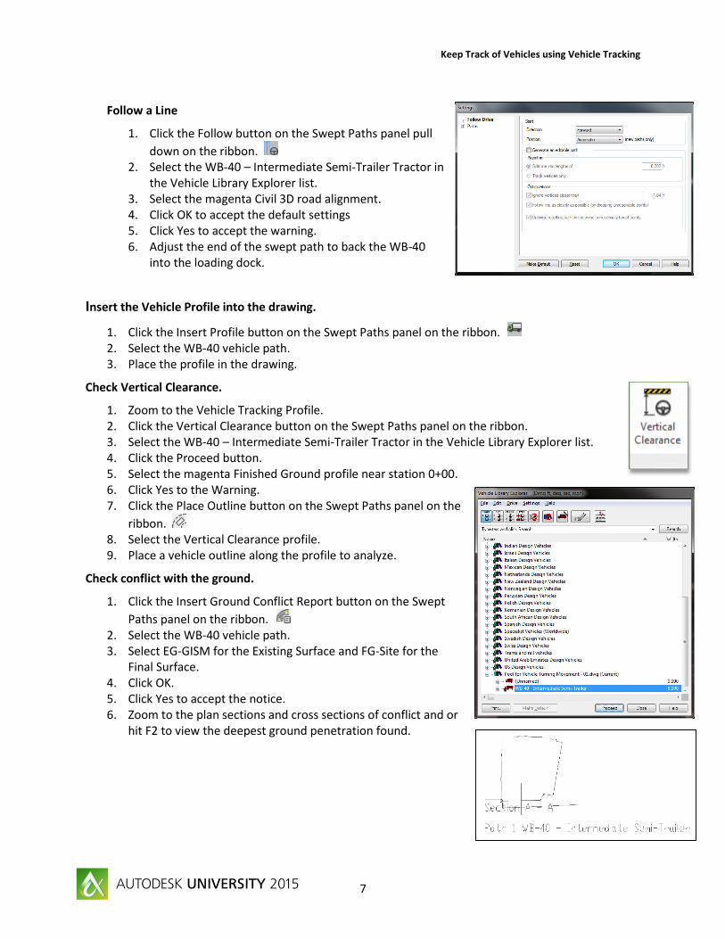
Follow a Line
1. Click the Follow button on the Swept Paths panel pull
down on the ribbon. 2. Select the WB-40 – Intermediate Semi-Trailer Tractor in
the Vehicle Library Explorer list. 3. Select the magenta Civil 3D road alignment. 4. Click OK to accept the default settings 5. Click Yes to accept the warning. 6. Adjust the end of the swept path to back the WB-40
into the loading dock.
Insert the Vehicle Profile into the drawing.
1. Click the Insert Profile button on the Swept Paths panel on the ribbon. 2. Select the WB-40 vehicle path. 3. Place the profile in the drawing.
Check Vertical Clearance.
1. Zoom to the Vehicle Tracking Profile. 2. Click the Vertical Clearance button on the Swept Paths panel on the ribbon. 3. Select the WB-40 – Intermediate Semi-Trailer Tractor in the Vehicle Library Explorer list. 4. Click the Proceed button. 5. Select the magenta Finished Ground profile near station 0+00. 6. Click Yes to the Warning. 7. Click the Place Outline button on the Swept Paths panel on the
ribbon. 8. Select the Vertical Clearance profile. 9. Place a vehicle outline along the profile to analyze.
Check conflict with the ground.
1. Click the Insert Ground Conflict Report button on the Swept
Paths panel on the ribbon. 2. Select the WB-40 vehicle path. 3. Select EG-GISM for the Existing Surface and FG-Site for the
Final Surface. 4. Click OK. 5. Click Yes to accept the notice. 6. Zoom to the plan sections and cross sections of conflict and or
hit F2 to view the deepest ground penetration found.
Keep Track of Vehicles using Vehicle Tracking
8
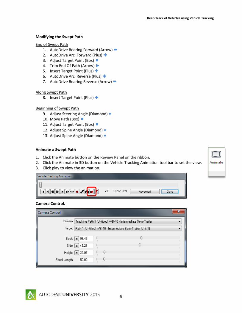
Modifying the Swept Path
End of Swept Path 1. AutoDrive Bearing Forward (Arrow) 2. AutoDrive Arc Forward (Plus) 3. Adjust Target Point (Box) 4. Trim End Of Path (Arrow) ► 5. Insert Target Point (Plus) 6. AutoDrive Arc Reverse (Plus) 7. AutoDrive Bearing Reverse (Arrow)
Along Swept Path 8. Insert Target Point (Plus)
Beginning of Swept Path
9. Adjust Steering Angle (Diamond) ♦ 10. Move Path (Box) 11. Adjust Target Point (Box)
12. Adjust Spine Angle (Diamond) ♦
13. Adjust Spine Angle (Diamond) ♦
Animate a Swept Path
1. Click the Animate button on the Review Panel on the ribbon. 2. Click the Animate in 3D button on the Vehicle Tracking Animation tool bar to set the view. 3. Click play to view the animation.
Camera Control.

Keep Track of Vehicles using Vehicle Tracking
9
Roundabout Junctions
1. Open Roundabout Junction Design - 01.dwg in the project folder. 2. Click the Vehicle Tracking tab on the Ribbon. 3. Click the New Roundabout button on the Junctions panel on the ribbon. This will launch
the Junction Standard Explorer. 4. Select the US Federal Highways Administration guideline, Roundabouts: An Informational
Guide 2010 the FHWA 2010: Rural Single Lane Roundabout for this lab. 5. Click Proceed to continue. 6. Click Yes to set as default standard for this project. 7. Click OK to accept the drawing scale of 1 unit = 1 feet. 8. Name the junction “Roundabout”. 9. Click OK to continue. 10. Place Roundabout at the intersection. 11. Right click or press Enter to accept the placement.
Modifying the Junction Object.
1. Adjust Roundabout Center Point (Box) 2. Move Entire Junction (Box) 3. Adjust Island Radius (Box) 4. Adjust Apron Width (Box) 5. Adjust Inscribed Radius (Box)
Add Approach and Departure Roads.
1. Click the New Road button on the Junctions panel on the ribbon. 2. Select the Junction object. 3. Select the North approach road centerline. 4. Name the New Leg “Road North”. 5. Click OK. 6. Select the south approach road centerline. 7. Name the New Leg “Road South”. 8. Click OK. 9. Continue creating the East and West approach roads. 10. Right click or press Enter to accept the placement.
Add Splitter Islands.
1. Click the New Splitter Island button on the Junctions panel. 2. Select the roundabout junction object. 3. Select the location of the splitter island. A green plus will appear at the location. 4. Click to place the splitter island then repeat to place additional splitter islands around the
junction.
Modify the Splitter Island.
1. Adjust the left and right width of the splitter island (Arrow) ►

Keep Track of Vehicles using Vehicle Tracking
10
Add Cross Walks.
1. Click the New Crosswalk button on the Junctions panel. 2. Select the roundabout junction object. 3. Select the location of the crosswalk. The crosswalk striping object will appear. 4. Click to place the crosswalk striping then repeat to place additional crosswalk striping around
the junction.
Modify the Crosswalk.
1. Adjust the offset location of the crosswalk (Box) 2. Adjust the width of the crosswalk (Box)
Add Speed Striping.
1. Click the New Speed Striping button on the Junctions panel. 2. Select the roundabout junction object. 3. Select the location of the speed striping. The speed striping object will appear. 4. Click to place the speed striping then repeat to place additional speed striping around the
junction.
Modify the Speed Striping.
1. Adjust Speed Strip Inner Offset (Box) 2. Adjust Speed Strip Inner Spacing (Box) 3. Adjust Speed Strip Outer Offset (Box) 4. Adjust Speed Strip Outer Spacing (Box)
Add Rumble Strips.
1. Click the New Rumble Strips button on the Junctions panel. 2. Select the roundabout junction object. 3. Select the location of the rumble strips. The rumble strips object will appear. 4. Click at the location and repeat to place additional rumble strips.
Modify the Rumble Strips.
1. Adjust Rumble Strip Inner Offset (Box) 2. Adjust Rumble Strip Inner Spacing (Box) 3. Adjust Rumble Strip Outer Offset (Box) 4. Adjust Rumble Strip Outer Spacing (Box)

Keep Track of Vehicles using Vehicle Tracking
11
Edit the Roundabout Junction
All the parameters of a roundabout junction can be modified in the Junction Properties dialog box.
Note: The roundabout corridor can be created based on a surface or profiles.
1. Open Roundabout Junction Design - 02.dwg in the project folder.
2. Click the Edit Roundabout button on the Junctions panel. 3. Select the roundabout junction object. 4. Set the Existing Surface to RG-GISM. 5. Click Apply. 6. Expand the Roundel element then Crown Lines in the left panel. 7. Set Primary Crown Line Offset % to 100. 8. Click Levels & Grades. 9. Set Take Elevation From to User Defined Elevation. 10. Set Elevation at Center to 277.27. 11. Click Apply. 12. Expand Road North then Levels & Grades. 13. Set Take Elevation and Grade From to Profile: Entrance Road FGCL. 14. Do the same for the South, East and West Roads. 15. Additional settings shown on page 12 of this handout. 16. Click Apply but do not close.
Create a Corridor.
1. Click the 3D Corridor element. 2. Check Create Alignments and Create Corridor. 3. Click the Rebuild Now button then click Close.
Note: Creating a corridor also creates the associated assemblies. These assemblies can be modified to suit the design such as adding curbing, sidewalks and daylighting.
Create a Surface from the corridor.
1. Select the corridor. 2. Click the Corridor Properties on the Ribbon. 3. Click the Surfaces tab. 4. Click the Create a Corridor Surface button. 5. Name the surface FG-CORRIDOR. 6. Select the Top Code then click the plus button. 7. Click the Boundary tab. 8. Right Click the surface name. 9. Click Corridor Extents as Outer Boundary. 10. Click OK.

Keep Track of Vehicles using Vehicle Tracking
12

Keep Track of Vehicles using Vehicle Tracking
13
Thanks for attending!