chunky graphite in ferritic spheroidal graphite cast iron ...ferritic spheroidal graphite cast iron...
TRANSCRIPT
CHUNKY GRAPHITE IN FERRITIC SPHEROIDAL GRAPHITE CAST IRON: FORMATION,PREVENTION, CHARACTERIZATION, IMPACT ON PROPERTIES: AN OVERVIEW
Wolfram BaerFederal Institute for Materials Research and Testing (BAM), Unter den Eichen 87, 12205 Berlin, Germany
Copyright � 2019 The Author(s)
https://doi.org/10.1007/s40962-019-00363-8
Abstract
Ferritic spheroidal graphite cast iron (SGI) materials have
a remarkable technical potential and economic impact in
modern industry. These features are closely related to the
question of how the cast materials can be produced without
structural defects and graphite degenerations such as, for
example, chunky graphite. Although the chunky graphite
degeneration superficially seems to be well known, its
metallurgical background is still controversially discussed,
appropriate field-tested nondestructive tools for its quan-
tification in castings are lacking, and the knowledge on its
impact on material properties is fairly limited. Addressing
this status, the article is providing a current overview on
the subject. Existing theories on formation and growth
mechanisms of chunky graphite are briefly reviewed. Fur-
thermore, from a metallurgical point of view, causes for the
appearance of chunky graphite as well as preventive
measures are concisely summarized. Particular attention is
paid to the morphology of chunky graphite and how it can
be characterized by destructive and nondestructive tech-
niques. Special emphasis was laid on providing a com-
prehensive overview on the impact of chunky graphite on
strength, ductility, fatigue limit, fatigue crack growth rate
as well as fracture toughness of ferritic SGI materials
based on experimental data. Moreover, conclusions for the
assessment of castings affected by chunky graphite are
drawn.
Keywords: ferritic spheroidal graphite cast iron, chunky
graphite, properties, formation, prevention,
characterization
Introduction
A combination of outstanding attributes makes ferritic
spheroidal graphite cast iron (SGI) materials increasingly
attractive to designers. Due to their remarkable mechanical
properties, fracture toughness, design freedom, castability,
energy efficiency due to low melting and pouring temper-
atures, machinability and cost-effectiveness, there is a
continuously growing demand for complex, frequently
heavy-sectioned SGI castings.1–5 Outstanding application
fields are the wind energy, metal forming and nuclear
industries, e.g., casks for storage and transport of nuclear
materials. To assure the specified properties, the absence of
structural defects and very high degrees of graphite nodu-
larity are requested. Nevertheless, graphite degenera-
tions—among which chunky graphite (CHG) is seen to be
the most common and detrimental one—may occur in the
castings under certain circumstances. The formation
probability of such degenerations significantly increases
with heavy sections above wall thicknesses of
approximately 100–200 mm and solidification times longer
than approximately 1 h.6–8 However, chunky graphite has
occasionally been observed even in 10-mm-thick castings.9
CHG has been reported to be a major problem with nickel-
containing austenitic ductile iron materials10 as well, but
this is outside the scope of this article.
Up to now, nondestructive testing technologies to detect
chunky graphite in castings have not been established
successfully.6 A solitary report was identified which sug-
gests the possibility to detect chunky graphite regions in
SGI by changes in ultrasonic characteristics (sound
velocity and bottom echo).11 Frequently, the presence of
chunky graphite degeneration becomes obvious not before
the mechanical machining of the component when dark
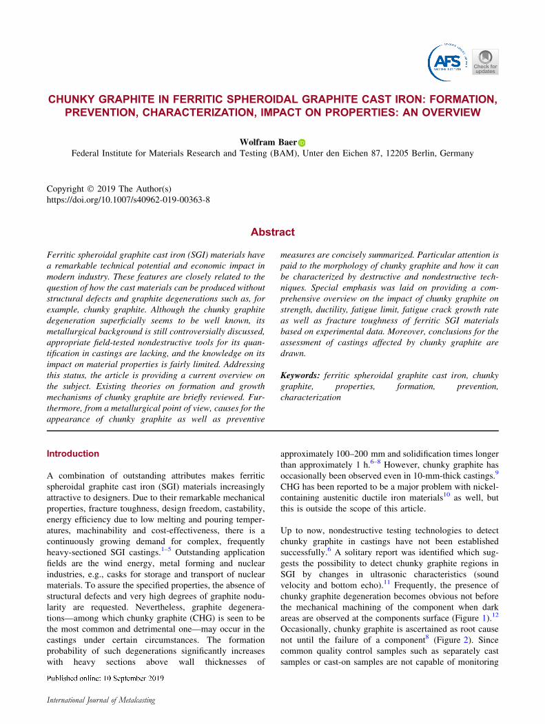
areas are observed at the components surface (Figure 1).12
Occasionally, chunky graphite is ascertained as root cause
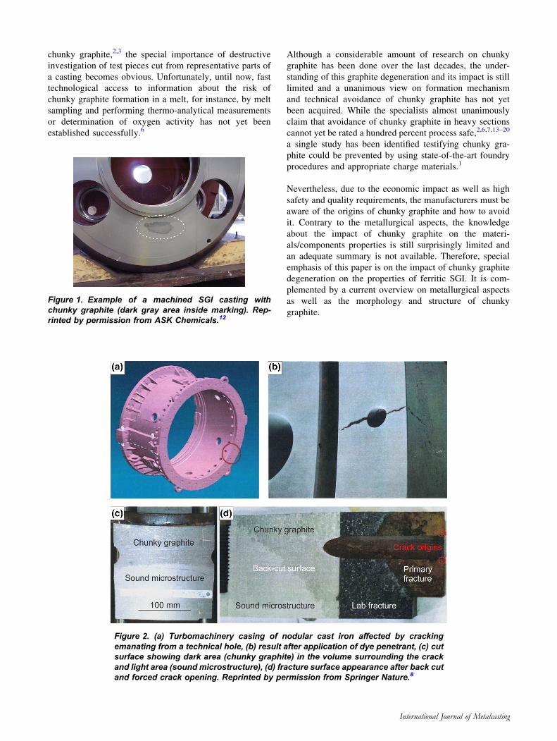
not until the failure of a component8 (Figure 2). Since
common quality control samples such as separately cast
samples or cast-on samples are not capable of monitoring
International Journal of Metalcasting
chunky graphite,2,3 the special importance of destructive
investigation of test pieces cut from representative parts of
a casting becomes obvious. Unfortunately, until now, fast
technological access to information about the risk of
chunky graphite formation in a melt, for instance, by melt
sampling and performing thermo-analytical measurements
or determination of oxygen activity has not yet been
established successfully.6
Although a considerable amount of research on chunky
graphite has been done over the last decades, the under-
standing of this graphite degeneration and its impact is still
limited and a unanimous view on formation mechanism
and technical avoidance of chunky graphite has not yet
been acquired. While the specialists almost unanimously
claim that avoidance of chunky graphite in heavy sections
cannot yet be rated a hundred percent process safe,2,6,7,13–20
a single study has been identified testifying chunky gra-
phite could be prevented by using state-of-the-art foundry
procedures and appropriate charge materials.1
Nevertheless, due to the economic impact as well as high
safety and quality requirements, the manufacturers must be
aware of the origins of chunky graphite and how to avoid
it. Contrary to the metallurgical aspects, the knowledge
about the impact of chunky graphite on the materi-
als/components properties is still surprisingly limited and
an adequate summary is not available. Therefore, special
emphasis of this paper is on the impact of chunky graphite
degeneration on the properties of ferritic SGI. It is com-
plemented by a current overview on metallurgical aspects
as well as the morphology and structure of chunky
graphite.
Figure 1. Example of a machined SGI casting withchunky graphite (dark gray area inside marking). Rep-rinted by permission from ASK Chemicals.12
Figure 2. (a) Turbomachinery casing of nodular cast iron affected by crackingemanating from a technical hole, (b) result after application of dye penetrant, (c) cutsurface showing dark area (chunky graphite) in the volume surrounding the crackand light area (sound microstructure), (d) fracture surface appearance after back cutand forced crack opening. Reprinted by permission from Springer Nature.8
International Journal of Metalcasting
Formation and Growth of Chunky Graphite
The room temperature graphite morphology in cast Fe–C–
Si alloys is basically the result of nucleation from the liquid
melt and graphite crystal growth followed by solid-state
carbon diffusion growth. The chemical complexity of the
iron melts and the transitory nature of nucleation and local
segregation produced by chemical alloy composition, melt
treatment and casting conditions are the main governing
factors. The interaction between these variables can pro-
duce a large variety of graphite shapes including lamellar/
flake (LG), compacted/vermicular (CG), spheroidal/nodu-
lar (SG) and temper graphite (TG), as well as some
degenerated morphologies, such as spiky, exploded or
chunky graphite (CHG).21 This illustrates the complexity
of graphite crystallization and growth in iron melts. Con-
sidering the above-mentioned graphite formation steps, it is
emphasized in Reference 22 that the growth step is most
important for the final graphite shape. It is not the intention
of this paper to present a detailed, wide-ranging overview
on graphite formation from a more general point of view.
This subject has recently thoroughly and comprehensively
been reviewed, for instance, in References 21, 22 and 23.
In the present article, it is rather a question of treating and
consolidating the subject focusing on chunky graphite. In
particular, the studies6,9,13,19,21–26 especially contribute.
Although several theories on the formation and growth of
chunky graphite in SGI have been proposed, a universal,
unanimously accepted explanation has not yet been estab-
lished. While the growth of lamellar graphite is fairly well
understood, that of compacted, chunky and spheroidal
graphite is still in the focus of research.24 The growth
mechanism of chunky graphite has recently even termed
far from being understood.27 Known models for chunky
graphite emphasize different aspects, partly complement
each other, but simultaneously they are contradictory in
parts. Kallbom9 provided a valuable and detailed overview
in which five approaches to the formation and growth of
CHG are classified. These theories are cited here briefly in
the following subsections (1) to (5) and occasionally
complemented by further studies. The subsections (6) and
(7) provide additional aspects contributing to a better
understanding of CHG formation and growth. Moreover,
very recent findings, mainly from,21,23,24 are incorporated
in subsections (8) and (9). At the end of this chapter,
preliminary conclusions on the formation and growth of
chunky graphite are drawn.
1. Pursuant to an early proposal of Karsay et al.,28
chunky graphite emanates from small pieces
broken off the ordinary graphite nodules. Due
to thermal currents and growth stresses, the
nodules can break into sectors (chunks) and be
dispersed to interdendritic spaces. Carbon can
diffuse from the melt and be deposited on the
chunks changing their appearance and subse-
quently causing the characteristic graphite inter-
connections. Today, this theory has been ruled
out by the later finding that chunky graphite
grows interconnected.29
2. Liu et al.30 proposed a helical growth mechanism
where chunky graphite is composed by a series of
clustered, sector-shaped graphite segments.
Branching is ascribed to microsegregation of
certain elements like cerium and others. Chunky
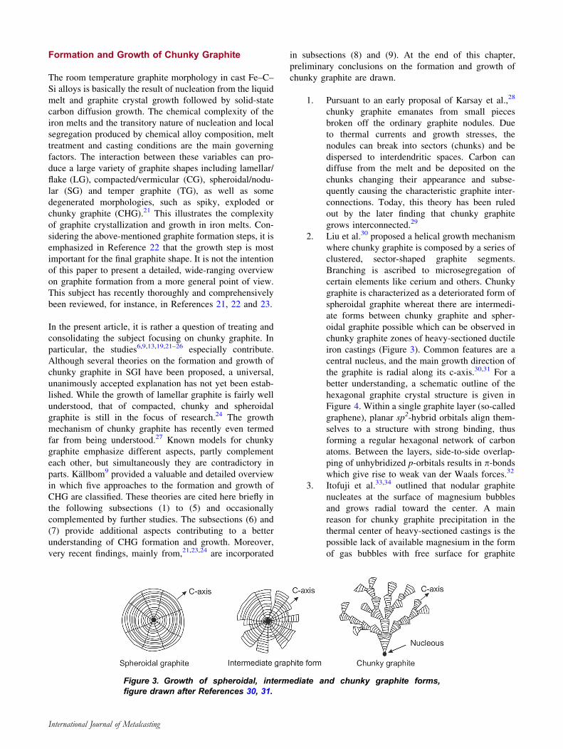
graphite is characterized as a deteriorated form of
spheroidal graphite whereat there are intermedi-
ate forms between chunky graphite and spher-
oidal graphite possible which can be observed in
chunky graphite zones of heavy-sectioned ductile
iron castings (Figure 3). Common features are a
central nucleus, and the main growth direction of
the graphite is radial along its c-axis.30,31 For a
better understanding, a schematic outline of the
hexagonal graphite crystal structure is given in
Figure 4. Within a single graphite layer (so-called
graphene), planar sp2-hybrid orbitals align them-
selves to a structure with strong binding, thus
forming a regular hexagonal network of carbon
atoms. Between the layers, side-to-side overlap-
ping of unhybridized p-orbitals results in p-bondswhich give rise to weak van der Waals forces.32
3. Itofuji et al.33,34 outlined that nodular graphite
nucleates at the surface of magnesium bubbles
and grows radial toward the center. A main
reason for chunky graphite precipitation in the
thermal center of heavy-sectioned castings is the
possible lack of available magnesium in the form
of gas bubbles with free surface for graphite
Figure 3. Growth of spheroidal, intermediate and chunky graphite forms,figure drawn after References 30, 31.
International Journal of Metalcasting
formation. Further reasons for a lack of available
magnesium may be a second oxidation during
pouring, reaction with refractory35 or fading out
by floating of gas bubbles and metallic magne-
sium segregation at the austenite–residual melt
interface.36
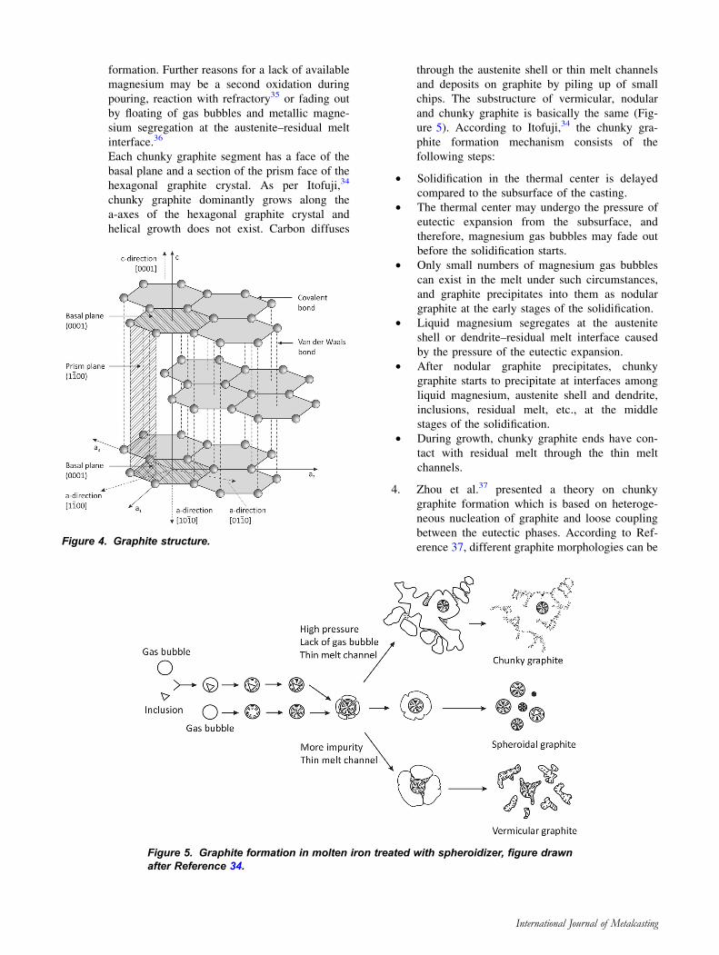
Each chunky graphite segment has a face of the
basal plane and a section of the prism face of the
hexagonal graphite crystal. As per Itofuji,34
chunky graphite dominantly grows along the
a-axes of the hexagonal graphite crystal and
helical growth does not exist. Carbon diffuses
through the austenite shell or thin melt channels
and deposits on graphite by piling up of small
chips. The substructure of vermicular, nodular
and chunky graphite is basically the same (Fig-
ure 5). According to Itofuji,34 the chunky gra-
phite formation mechanism consists of the
following steps:
• Solidification in the thermal center is delayed
compared to the subsurface of the casting.
• The thermal center may undergo the pressure of
eutectic expansion from the subsurface, and
therefore, magnesium gas bubbles may fade out
before the solidification starts.
• Only small numbers of magnesium gas bubbles
can exist in the melt under such circumstances,
and graphite precipitates into them as nodular
graphite at the early stages of the solidification.
• Liquid magnesium segregates at the austenite
shell or dendrite–residual melt interface caused
by the pressure of the eutectic expansion.
• After nodular graphite precipitates, chunky
graphite starts to precipitate at interfaces among
liquid magnesium, austenite shell and dendrite,
inclusions, residual melt, etc., at the middle
stages of the solidification.
• During growth, chunky graphite ends have con-
tact with residual melt through the thin melt
channels.
4. Zhou et al.37 presented a theory on chunky
graphite formation which is based on heteroge-
neous nucleation of graphite and loose coupling
between the eutectic phases. According to Ref-
erence 37, different graphite morphologies can beFigure 4. Graphite structure.
Figure 5. Graphite formation in molten iron treated with spheroidizer, figure drawnafter Reference 34.
International Journal of Metalcasting
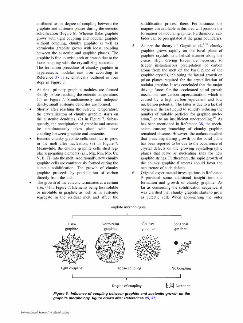
attributed to the degree of coupling between the
graphite and austenite phases during the eutectic
solidification (Figure 6). Whereas flake graphite
grows with tight coupling and nodular graphite
without coupling, chunky graphite as well as
vermicular graphite grows with loose coupling
between the austenite and graphite phases. The
graphite is free to twist, arch or branch due to the
loose coupling with the crystallizing austenite.
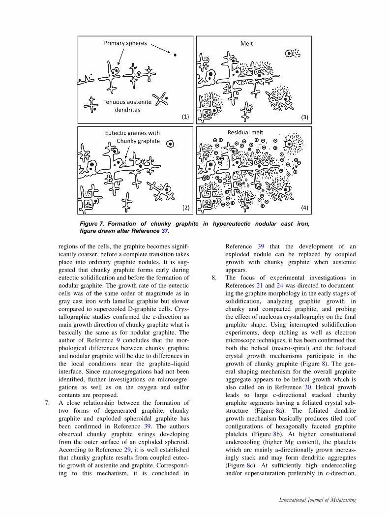
The formation procedure of chunky graphite in
hypereutectic nodular cast iron according to
Reference 37 is schematically outlined in four
steps in Figure 7.
• At first, primary graphite nodules are formed
shortly before reaching the eutectic temperature,
(1) in Figure 7. Simultaneously and indepen-
dently, small austenite dendrites are formed.
• Shortly after reaching the eutectic temperature,
the crystallization of chunky graphite starts on
the austenite dendrites, (2) in Figure 7. Subse-
quently, the precipitation of graphite and austen-
ite simultaneously takes place with loose
coupling between graphite and austenite.
• Eutectic chunky graphite cells continue to grow
in the melt after nucleation, (3) in Figure 7.
Meanwhile, the chunky graphite cells shed reg-
ular segregating elements (i.e., Mg, Mn, Mo, Cr,
V, B, Ti) into the melt. Additionally, new chunky
graphite cells are continuously formed during the
eutectic solidification. The growth of chunky
graphite proceeds by precipitation of carbon
directly from the melt.
• The growth of the eutectic terminates at a certain
size, (4) in Figure 7. Elements being less soluble
or insoluble in graphite as well as in austenite
segregate in the residual melt and affect the
solidification process there. For instance, the
magnesium available in this area will promote the
formation of nodular graphite. Furthermore, car-
bides can be precipitated at the grain boundaries.
5. As per the theory of Gagne et al.,1,38 chunky
graphite grows rapidly on the basal plane of
graphite crystals in a helical manner along the
c-axis. High driving forces are necessary to
trigger instantaneous precipitation of carbon
atoms from the melt on the basal plane of the
graphite crystals, inhibiting the lateral growth on
prism planes required for the crystallization of
nodular graphite. It was concluded that the major
driving forces for the accelerated spiral growth
mechanism are carbon supersaturation, which is
caused by a high carbon equivalent and low
nucleation potential. The latter is due to a lack of
oxygen in the last liquid to solidify reducing the
number of suitable particles for graphite nucle-
ation,9 or to an insufficient undercooling.10 As
has been mentioned in Reference 38, the mech-
anism causing branching of chunky graphite
remained obscure. However, the authors recalled
that branching during growth on the basal plane
has been reported to be due to the occurrence of
crystal defects on the growing crystallographic
planes that serve as nucleating sites for new
graphite strings. Furthermore, the rapid growth of
the chunky graphite filaments should favor the
occurrence of such defects.
6. Original experimental investigations in Reference
9 provided some additional insight into the
formation and growth of chunky graphite. As
far as concerning the solidification sequence, it
was clarified that chunky graphite starts to grow
as eutectic cell. When approaching the outer
Figure 6. Influence of coupling between graphite and austenite growth on thegraphite morphology, figure drawn after References 25, 37.
International Journal of Metalcasting
regions of the cells, the graphite becomes signif-
icantly coarser, before a complete transition takes
place into ordinary graphite nodules. It is sug-
gested that chunky graphite forms early during
eutectic solidification and before the formation of
nodular graphite. The growth rate of the eutectic
cells was of the same order of magnitude as in
gray cast iron with lamellar graphite but slower
compared to supercooled D-graphite cells. Crys-
tallographic studies confirmed the c-direction as
main growth direction of chunky graphite what is
basically the same as for nodular graphite. The
author of Reference 9 concludes that the mor-
phological differences between chunky graphite
and nodular graphite will be due to differences in
the local conditions near the graphite–liquid
interface. Since macrosegregations had not been
identified, further investigations on microsegre-
gations as well as on the oxygen and sulfur
contents are proposed.
7. A close relationship between the formation of
two forms of degenerated graphite, chunky
graphite and exploded spheroidal graphite has
been confirmed in Reference 39. The authors
observed chunky graphite strings developing
from the outer surface of an exploded spheroid.
According to Reference 29, it is well established
that chunky graphite results from coupled eutec-
tic growth of austenite and graphite. Correspond-
ing to this mechanism, it is concluded in
Reference 39 that the development of an
exploded nodule can be replaced by coupled
growth with chunky graphite when austenite
appears.
8. The focus of experimental investigations in
References 21 and 24 was directed to document-
ing the graphite morphology in the early stages of
solidification, analyzing graphite growth in
chunky and compacted graphite, and probing
the effect of nucleous crystallography on the final
graphite shape. Using interrupted solidification
experiments, deep etching as well as electron
microscope techniques, it has been confirmed that
both the helical (macro-spiral) and the foliated
crystal growth mechanisms participate in the
growth of chunky graphite (Figure 8). The gen-
eral shaping mechanism for the overall graphite
aggregate appears to be helical growth which is
also called on in Reference 30. Helical growth
leads to large c-directional stacked chunky
graphite segments having a foliated crystal sub-
structure (Figure 8a). The foliated dendrite
growth mechanism basically produces tiled roof
configurations of hexagonally faceted graphite
platelets (Figure 8b). At higher constitutional
undercooling (higher Mg content), the platelets
which are mainly a-directionally grown increas-
ingly stack and may form dendritic aggregates
(Figure 8c). At sufficiently high undercooling
and/or supersaturation preferably in c-direction,
Figure 7. Formation of chunky graphite in hypereutectic nodular cast iron,figure drawn after Reference 37.
International Journal of Metalcasting
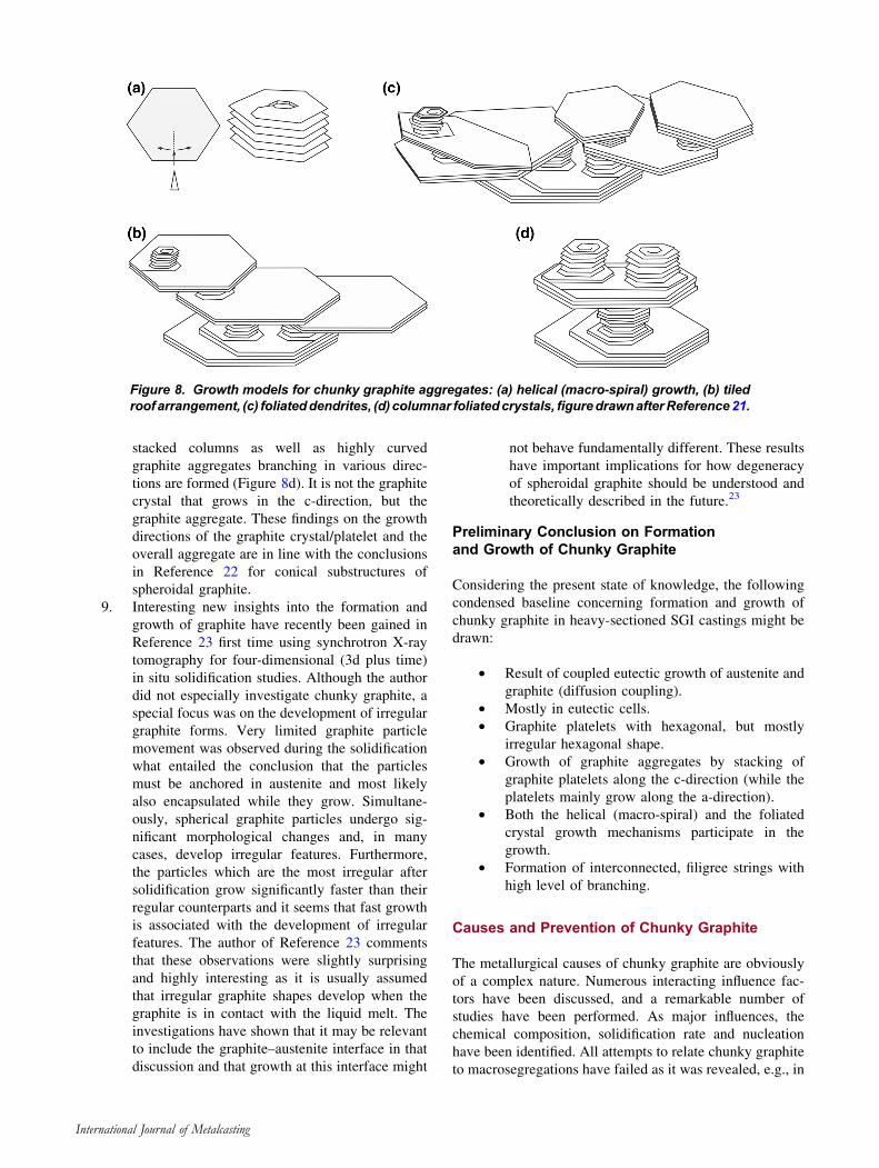
stacked columns as well as highly curved
graphite aggregates branching in various direc-
tions are formed (Figure 8d). It is not the graphite
crystal that grows in the c-direction, but the
graphite aggregate. These findings on the growth
directions of the graphite crystal/platelet and the
overall aggregate are in line with the conclusions
in Reference 22 for conical substructures of
spheroidal graphite.
9. Interesting new insights into the formation and
growth of graphite have recently been gained in
Reference 23 first time using synchrotron X-ray
tomography for four-dimensional (3d plus time)
in situ solidification studies. Although the author
did not especially investigate chunky graphite, a
special focus was on the development of irregular
graphite forms. Very limited graphite particle
movement was observed during the solidification
what entailed the conclusion that the particles
must be anchored in austenite and most likely
also encapsulated while they grow. Simultane-
ously, spherical graphite particles undergo sig-
nificant morphological changes and, in many
cases, develop irregular features. Furthermore,
the particles which are the most irregular after
solidification grow significantly faster than their
regular counterparts and it seems that fast growth
is associated with the development of irregular
features. The author of Reference 23 comments
that these observations were slightly surprising
and highly interesting as it is usually assumed
that irregular graphite shapes develop when the
graphite is in contact with the liquid melt. The
investigations have shown that it may be relevant
to include the graphite–austenite interface in that
discussion and that growth at this interface might
not behave fundamentally different. These results
have important implications for how degeneracy
of spheroidal graphite should be understood and
theoretically described in the future.23
Preliminary Conclusion on Formationand Growth of Chunky Graphite
Considering the present state of knowledge, the following
condensed baseline concerning formation and growth of
chunky graphite in heavy-sectioned SGI castings might be
drawn:
• Result of coupled eutectic growth of austenite and
graphite (diffusion coupling).
• Mostly in eutectic cells.
• Graphite platelets with hexagonal, but mostly
irregular hexagonal shape.
• Growth of graphite aggregates by stacking of
graphite platelets along the c-direction (while the
platelets mainly grow along the a-direction).
• Both the helical (macro-spiral) and the foliated
crystal growth mechanisms participate in the
growth.
• Formation of interconnected, filigree strings with
high level of branching.
Causes and Prevention of Chunky Graphite
The metallurgical causes of chunky graphite are obviously
of a complex nature. Numerous interacting influence fac-
tors have been discussed, and a remarkable number of
studies have been performed. As major influences, the
chemical composition, solidification rate and nucleation
have been identified. All attempts to relate chunky graphite
to macrosegregations have failed as it was revealed, e.g., in
Figure 8. Growth models for chunky graphite aggregates: (a) helical (macro-spiral) growth, (b) tiledroof arrangement, (c) foliateddendrites, (d) columnar foliatedcrystals, figuredrawnafterReference21.
International Journal of Metalcasting
References 1, 7, 9, 29 and 40. Noteworthy insight into
causes and prevention of chunky graphite is provided, for
example, in References 6, 13, 25, 27, 29, 41 and 42.
Nevertheless, the published data are partly contradictory,
its variation is broadly based, and the particularly discussed
influence parameters are often interrelated. Thus, deducing
strict rules for causes and prevention of CHG is
complicated.
Effect of Chemical Elements
The solidification of SGI, which is the main driver of
casting properties,43 follows the eutectic system Fe–C–Si.
With respect to the microstructure required for a particular
SGI grade, a ferritic matrix is basically achieved by lim-
iting pearlite stabilizing elements. An empirical estimation
tool to control the pearlite stabilizing effect of chemical
elements was reported in Reference 44. According to
Reference 44 Px is the so-called pearlite number and cal-
culated by Eqn. 1.
Px ¼ 3:00wMn � 2:65 wSi � 2:00ð Þ þ 7:75wCu þ 90:00wSn
þ 357:00wPb þ 333:00wBi þ 20:10wAs þ 9:60wCr
þ 71:70wSb
Eqn: 1
where wi stands for the content of the element ‘‘i’’ in wt%.
The ferrite share F of the SGI matrix is then given by
Eqn. 2:
F ¼ 961 � e�Px Eqn: 2
As follows fromEqns. 1 and 2,Mn, Cu, Sn, Pb, Bi, As, Cr and
Sb promote pearlite, thus preventing ferritewhich is in fact the
basis of the SGI key properties ductility and toughness. It is
worth noting at this place that the positive influence of ferrite
on ductility and toughness is mainly controlled by the Si
solution strengthening level and the ferrite grain size. On the
other hand, going back to,38,45 it is concluded in Reference 3
that despite that the controlled addition of Sb, Sn, Mn and Cu
will promote the formation of pearlite, it simultaneously
suppresses the formation of chunky graphite. According to
Reference 38, the underlying mechanism is seen in the
diffusion of carbon to the graphite particles which is
decelerated, and thus, the carbon supersaturation level on
the basal plane of the graphite is effectively lowered.
Basically, there is qualitative agreement about the impor-
tance of the carbon equivalent parameter (CE) for the
appearance of chunky graphite in SGI. CE conflates the
major SGI alloying elements silicon and carbon as well as
some other elements depending on the CE definition. Since
there are different CE definitions in use and publications
may show a lack of specifying information, care should be
taken assessing concrete CE values. Moreover, it may be
noted that the CE values should differ for non-inoculated
and inoculated castings from the same melt.46 Although, in
principle, the CE parameter should be set slightly
hypoeutectic to prevent formation of primary graphite and
graphite flotation, the recommendations to avoid chunky
graphite in heavy sections cover a CE range of 4.0–4.5% as
established by References 3, 6, 9, 30, 33, 42 and 47, but the
finding of non-sensitivity16 as well. Special importance of
the CE parameter has been pronounced in Reference 48
stating that effort should be made to modify CE or heat
exchange parameters before Sb is used as a remedy for
chunky graphite.
Published studies reveal different quantitative results on a
maximum tolerable Si content (1.8–2.4%) depending on
the solidification time (wall thickness) and the contents of
trace elements (also called tramp or accompanying
elements).6,9,13,25,33,37,41,42,49
With the recently standardized grades of solid solution-
strengthened ferritic SGI, the Si content is a matter of
special interest.50–52 With these SGI grades, Si is limited to
approximately 4.2%50 since above this limit Fe–Si super-
structures gain detrimental influence on the mechanical
properties53–55 and chunky graphite appears. Consequently,
a chunky graphite-free microstructure is closely related to
the acting combination of Si and trace elements and the
solidification time which itself corresponds to the wall
thickness. Therefore, the structural application potential of
solid solution-strengthened SGI grades has been limited up
to now with respect to the producible maximum wall
thickness.2,6,53 However, recent systematic investiga-
tions51,52 considering two large series of SGI melts fea-
turing high Si contents (altogether 50 alloys within
3.88% B Si B 6.14% as well as one alloy with 2.29% and
9.12%, respectively) revealed that the amount of chunky
graphite can significantly be reduced by the addition of Sb.
That means the critical Si level can be increased when Sb is
added. In a number of alloys, Sb additions were effective
for decreasing the formation of chunky graphite even at Si
contents higher than 6%. Based on the mechanical prop-
erties of the observed data base, which will be part of the
discussion in later in this article, the authors of Reference
52 suggest a possible Si content as high as 5.0% could be
considered for industrial applications when high resistance
and some ductility are requested.
Apart from the aforementioned major alloying elements C
and Si, the contents of trace elements must be limited to
prevent segregation and graphite degeneration. This task has
become very challenging for the foundries in recent years.
Due to today’s extraordinarily high variety of modern steels,
e.g., in automotive tailored blanks, the available steel scrap is
characterized by increased and frequently partly unknown
contents of trace elements and an increased variation in
chemical composition as well.6 This makes process control
more complex and rises costs with the foundries.
Trace elements can be assorted into two groups as far as
concerning the metallurgical promotion or inhibition of
International Journal of Metalcasting
chunky graphite. General understanding is that Ce, Ca, Cu,
Ni, Si, Al and rare earth metals (RE) promote (the so-called
chunky group going back to Reference 28), whereas Bi, Pb,
Sb, Sn, Cu and As (the so-called flake group28) inhibit the
formation of chunky graphite.2,6,9,12,13,18,19,25,31,39,56–58
Note that Cu has been mentioned in the literature as both a
chunky graphite inhibitor and promoter, e.g. References
6, 9 and 19.
Recent results on the role of RE16 even showed a positive
effect of very low-level Ce addition (0.004–0.005%) on
decreasing the amount of chunky graphite, while Reference
59 states a critical Ce amount of 0.0029% above which
exploded or chunky graphite could appear. It has been con-
firmed in Reference 39 that Ce can basically compensate the
detrimental effect of Pb on the graphite morphology. Indi-
vidual addition of Pb to the melt led to lamellar graphite and
lamellar outgrowths from graphite spheroids. By way of
contrast, combined addition of Ce and Pb suppressed
lamellae formation although excess of Ce in the melt pro-
moted degenerated spheroids and chunky graphite. The
findings of References 16 and 39 are basically in line with
earlier studies60,61 discussing an optimum RE content for a
maximum graphite nodularity which is sensitive to base
metal composition, process variables and section size. At
present, it seems to be generally accepted that RE (Ce)
contents should be kept at low levels not greater than
approximately 0.02% for prevention of chunky graphite.3,19
Boron has been reported to both promote6 and inhibit
chunky graphite.9,37 A beneficial effect of Zr and Sr has
been identified in Reference 62 when a fully nodular
microstructure without chunky graphite was obtained with
cubic blocks of 500 mm in edge using a combination of
rare earth-free MgFeSi with a Zr- and Sr-containing inoc-
ulant. On the other hand, Bi-containing inoculants gave
chunky graphite in Reference 62.
From the metallurgical point of view, oxygen, sulfur and
trace elements need to be controlled to achieve a stable Mg
treatment process. Owing to S and O being surface active
elements, they will boost prism plane growth of the gra-
phite as it is typical for chunky graphite.19
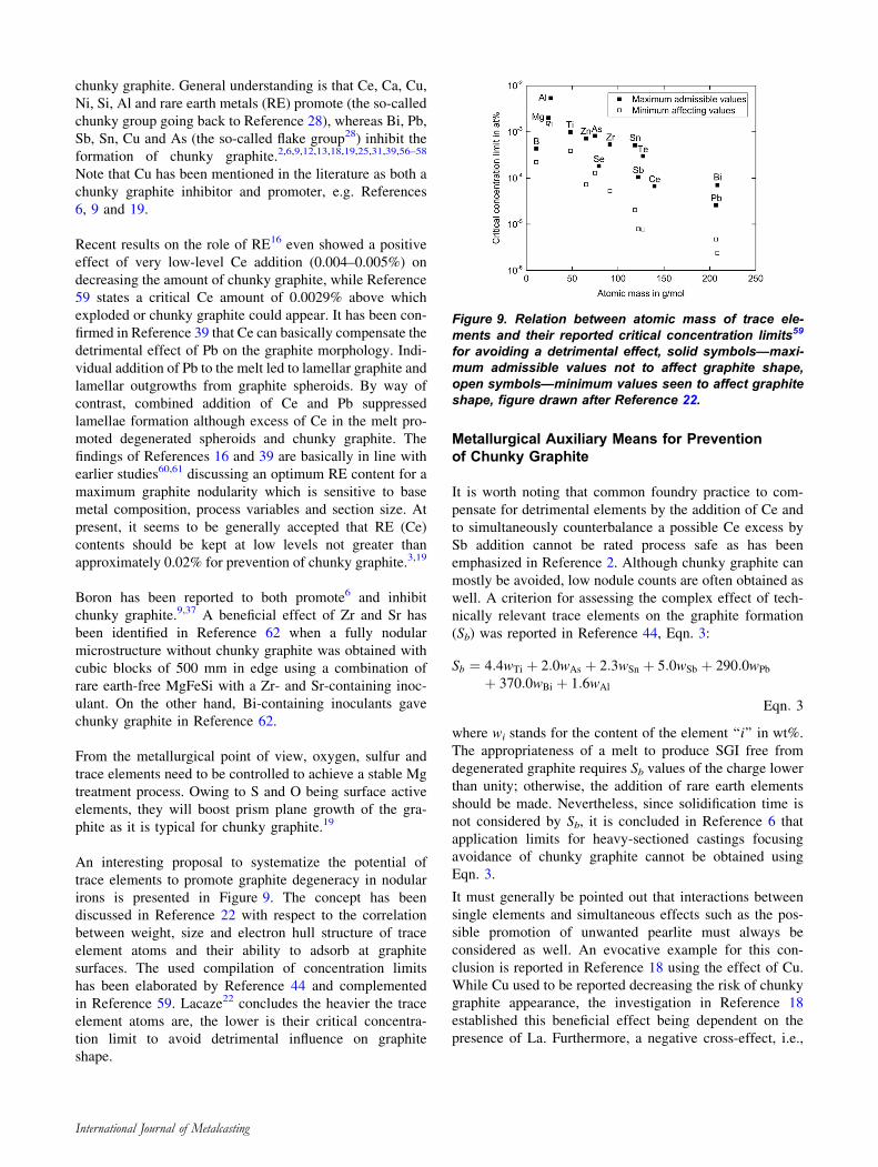
An interesting proposal to systematize the potential of
trace elements to promote graphite degeneracy in nodular
irons is presented in Figure 9. The concept has been
discussed in Reference 22 with respect to the correlation
between weight, size and electron hull structure of trace
element atoms and their ability to adsorb at graphite
surfaces. The used compilation of concentration limits
has been elaborated by Reference 44 and complemented
in Reference 59. Lacaze22 concludes the heavier the trace
element atoms are, the lower is their critical concentra-
tion limit to avoid detrimental influence on graphite
shape.
Metallurgical Auxiliary Means for Preventionof Chunky Graphite
It is worth noting that common foundry practice to com-
pensate for detrimental elements by the addition of Ce and
to simultaneously counterbalance a possible Ce excess by
Sb addition cannot be rated process safe as has been
emphasized in Reference 2. Although chunky graphite can
mostly be avoided, low nodule counts are often obtained as
well. A criterion for assessing the complex effect of tech-
nically relevant trace elements on the graphite formation
(Sb) was reported in Reference 44, Eqn. 3:
Sb ¼ 4:4wTi þ 2:0wAs þ 2:3wSn þ 5:0wSb þ 290:0wPb
þ 370:0wBi þ 1:6wAl
Eqn: 3
where wi stands for the content of the element ‘‘i’’ in wt%.
The appropriateness of a melt to produce SGI free from
degenerated graphite requires Sb values of the charge lower
than unity; otherwise, the addition of rare earth elements
should be made. Nevertheless, since solidification time is
not considered by Sb, it is concluded in Reference 6 that
application limits for heavy-sectioned castings focusing
avoidance of chunky graphite cannot be obtained using
Eqn. 3.
It must generally be pointed out that interactions between
single elements and simultaneous effects such as the pos-
sible promotion of unwanted pearlite must always be
considered as well. An evocative example for this con-
clusion is reported in Reference 18 using the effect of Cu.
While Cu used to be reported decreasing the risk of chunky
graphite appearance, the investigation in Reference 18
established this beneficial effect being dependent on the
presence of La. Furthermore, a negative cross-effect, i.e.,
Figure 9. Relation between atomic mass of trace ele-ments and their reported critical concentration limits59
for avoiding a detrimental effect, solid symbols—maxi-mum admissible values not to affect graphite shape,open symbols—minimum values seen to affect graphiteshape, figure drawn after Reference 22.
International Journal of Metalcasting
an increase in chunky graphite, was associated when Sb
was present as well. Perhaps, this complex behavior may
contribute to Cu being reported as inhibitor as well as
promoter of CHG, see discussion earlier in this article.
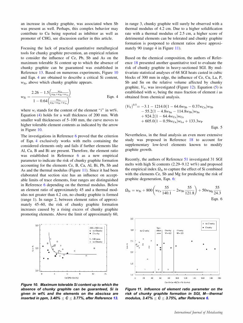
Focusing the lack of practical quantitative metallurgical
tools for chunky graphite prevention, an empirical relation
to consider the influence of Ce, Pb, Sb and As on the
maximum tolerable Si content up to which the absence of
chunky graphite can be guaranteed was established in
Reference 13. Based on numerous experiments, Figure 10
and Eqn. 4 are obtained to describe a critical Si content,
wSi, above which chunky graphite appears.
wSi ¼2:26� 1:5 wCe
wPbþwSbþwAs
� �
1� 0:64 wCe
wPbþwSbþwAs
� � Eqn: 4
where wi stands for the content of the element ‘‘i’’ in wt%.
Equation (4) holds for a wall thickness of 200 mm. With
smaller wall thicknesses of 5–100 mm, the curve moves to
higher tolerable element contents as indicated by the arrow
in Figure 10.
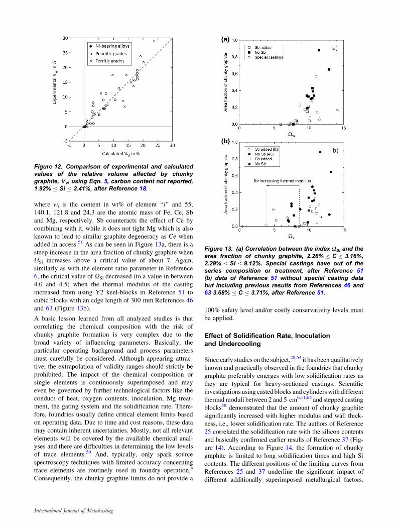
The investigations in Reference 6 proved that the criterion
of Eqn. 4 exclusively works with melts containing the
considered elements only and fails if further elements like
Al, Ca, B and Bi are present. Therefore, the element ratio
was established in Reference 6 as a new empirical
parameter to indicate the risk of chunky graphite formation
accounting for the elements Ce, B, Ca, Al, Bi, Pb, Sb and
As and the thermal modulus (Figure 11). Since it had been
elaborated that section size has an influence on accept-
able limits of trace elements, four ranges are distinguished
in Reference 6 depending on the thermal modulus. Below
an element ratio of approximately 45 and a thermal mod-
ulus not greater than 4.2 cm, no chunky graphite is formed
(range 1). In range 2, between element ratios of approxi-
mately 45–60, the risk of chunky graphite formation
increases caused by a rising excess of chunky graphite
promoting elements. Above the limit of approximately 60,
in range 3, chunky graphite will surely be observed with a
thermal modulus of 4.2 cm. Due to a higher solidification
rate with a thermal modulus of 2.5 cm, a higher score of
detrimental elements can be tolerated and chunky graphite
formation is postponed to element ratios above approxi-
mately 90 (range 4 in Figure 11).
Based on the chemical composition, the authors of Refer-
ence 18 presented another quantitative tool to evaluate the
risk of chunky graphite in heavy-sectioned SGI. By mul-
tivariate statistical analyses of 68 SGI heats casted in cubic
blocks of 300 mm in edge, the influence of Ce, Cu, La, P,
Sb and Sn on the relative volume affected by chunky
graphite, VV, was investigated (Figure 12). Equation (5) is
established with wi being the mass fraction of element i as
obtained from chemical analysis.
VVð Þ0:5¼ �3:1� 1214:0 1� 64:6wSb � 0:37wCuð ÞwSb
� 55:2 1� 4:8wSn � 114:8wSbð ÞwSn
þ 924:2 1� 64:4wCeð ÞwCe
þ 605:0 1� 0:59wCuð ÞwLa þ 133:3wP
Eqn: 5
Nevertheless, in the final analysis an even more extensive
study was proposed in Reference 18 to account for
supplementary low-level elements known to modify
graphite growth.
Recently, the authors of Reference 51 investigated 31 SGI
melts with high Si contents (2.29–9.12 wt%) and proposed
the empirical index XSi to capture the effect of Si combined
with the elements Ce, Sb and Mg for predicting the risk of
graphite degeneration, Eqn. 6:
XSi ¼ wSi þ 800 wCe
55
140:1� 2wSb
55
121:8
� �þ 50wMg
55
24:3
Eqn: 6
Figure 10. Maximum tolerable Si content up to which theabsence of chunky graphite can be guaranteed, Si isgiven in wt% and the elements on the abscissa areinserted in ppm, 3.40% B C B 3.77%, after Reference 13.
Figure 11. Influence of element ratio parameter on therisk of chunky graphite formation in SGI, M—thermalmodulus, 3.47% B C B 3.75%, after Reference 6.
International Journal of Metalcasting
where wi is the content in wt% of element ‘‘i’’ and 55,
140.1, 121.8 and 24.3 are the atomic mass of Fe, Ce, Sb
and Mg, respectively. Sb counteracts the effect of Ce by
combining with it, while it does not tight Mg which is also
known to lead to similar graphite degeneracy as Ce when
added in access.51 As can be seen in Figure 13a, there is a
steep increase in the area fraction of chunky graphite when
XSi increases above a critical value of about 7. Again,
similarly as with the element ratio parameter in Reference
6, the critical value of XSi decreased (to a value in between
4.0 and 4.5) when the thermal modulus of the casting
increased from using Y2 keel-blocks in Reference 51 to
cubic blocks with an edge length of 300 mm References 46
and 63 (Figure 13b).
A basic lesson learned from all analyzed studies is that
correlating the chemical composition with the risk of
chunky graphite formation is very complex due to the
broad variety of influencing parameters. Basically, the
particular operating background and process parameters
must carefully be considered. Although appearing attrac-
tive, the extrapolation of validity ranges should strictly be
prohibited. The impact of the chemical composition or
single elements is continuously superimposed and may
even be governed by further technological factors like the
conduct of heat, oxygen contents, inoculation, Mg treat-
ment, the gating system and the solidification rate. There-
fore, foundries usually define critical element limits based
on operating data. Due to time and cost reasons, these data
may contain inherent uncertainties. Mostly, not all relevant
elements will be covered by the available chemical anal-
yses and there are difficulties in determining the low levels
of trace elements.59 And, typically, only spark source
spectroscopy techniques with limited accuracy concerning
trace elements are routinely used in foundry operation.6
Consequently, the chunky graphite limits do not provide a
100% safety level and/or costly conservativity levels must
be applied.
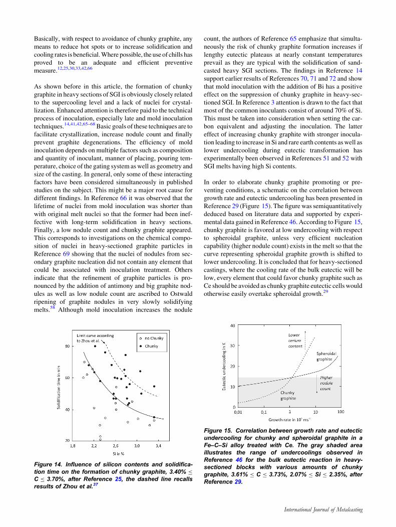
Effect of Solidification Rate, Inoculationand Undercooling
Since early studies on the subject,28,64 it has been qualitatively
known and practically observed in the foundries that chunky
graphite preferably emerges with low solidification rates as
they are typical for heavy-sectioned castings. Scientific
investigations using casted blocks and cylinderswith different
thermalmoduli between 2 and 5 cm6,11,65 and stepped casting
blocks58 demonstrated that the amount of chunky graphite
significantly increased with higher modulus and wall thick-
ness, i.e., lower solidification rate. The authors of Reference
25 correlated the solidification rate with the silicon contents
and basically confirmed earlier results of Reference 37 (Fig-
ure 14). According to Figure 14, the formation of chunky
graphite is limited to long solidification times and high Si
contents. The different positions of the limiting curves from
References 25 and 37 underline the significant impact of
different additionally superimposed metallurgical factors.
Figure 12. Comparison of experimental and calculatedvalues of the relative volume affected by chunkygraphite, VV, using Eqn. 5, carbon content not reported,1.92% B Si B 2.41%, after Reference 18.
Figure 13. (a) Correlation between the index XSi and thearea fraction of chunky graphite, 2.26% B C B 3.16%,2.29% B Si B 9.12%. Special castings have out of theseries composition or treatment, after Reference 51(b) data of Reference 51 without special casting databut including previous results from References 46 and63 3.68% B C B 3.71%, after Reference 51.
International Journal of Metalcasting
Basically, with respect to avoidance of chunky graphite, any
means to reduce hot spots or to increase solidification and
cooling rates is beneficial.Where possible, the use of chills has
proved to be an adequate and efficient preventive
measure.12,25,30,33,42,66
As shown before in this article, the formation of chunky
graphite in heavy sections of SGI is obviously closely related
to the supercooling level and a lack of nuclei for crystal-
lization. Enhanced attention is therefore paid to the technical
process of inoculation, especially late and mold inoculation
techniques.14,41,42,65–68 Basic goals of these techniques are to
facilitate crystallization, increase nodule count and finally
prevent graphite degenerations. The efficiency of mold
inoculation depends on multiple factors such as composition
and quantity of inoculant, manner of placing, pouring tem-
perature, choice of the gating system aswell as geometry and
size of the casting. In general, only some of these interacting
factors have been considered simultaneously in published
studies on the subject. This might be a major root cause for
different findings. In Reference 66 it was observed that the
lifetime of nuclei from mold inoculation was shorter than
with original melt nuclei so that the former had been inef-
fective with long-term solidification in heavy sections.
Finally, a low nodule count and chunky graphite appeared.
This corresponds to investigations on the chemical compo-
sition of nuclei in heavy-sectioned graphite particles in
Reference 69 showing that the nuclei of nodules from sec-
ondary graphite nucleation did not contain any element that
could be associated with inoculation treatment. Others
indicate that the refinement of graphite particles is pro-
nounced by the addition of antimony and big graphite nod-
ules as well as low nodule count are ascribed to Ostwald
ripening of graphite nodules in very slowly solidifying
melts.58 Although mold inoculation increases the nodule
count, the authors of Reference 65 emphasize that simulta-
neously the risk of chunky graphite formation increases if
lengthy eutectic plateaus at nearly constant temperatures
prevail as they are typical with the solidification of sand-
casted heavy SGI sections. The findings in Reference 14
support earlier results of References 70, 71 and 72 and show
that mold inoculation with the addition of Bi has a positive
effect on the suppression of chunky graphite in heavy-sec-
tioned SGI. In Reference 3 attention is drawn to the fact that
most of the common inoculants consist of around 70% of Si.
This must be taken into consideration when setting the car-
bon equivalent and adjusting the inoculation. The latter
effect of increasing chunky graphite with stronger inocula-
tion leading to increase in Si and rare earth contents aswell as
lower undercooling during eutectic transformation has
experimentally been observed in References 51 and 52 with
SGI melts having high Si contents.
In order to elaborate chunky graphite promoting or pre-
venting conditions, a schematic on the correlation between
growth rate and eutectic undercooling has been presented in
Reference 29 (Figure 15). The figure was semiquantitatively
deduced based on literature data and supported by experi-
mental data gained in Reference 46. According to Figure 15,
chunky graphite is favored at low undercooling with respect
to spheroidal graphite, unless very efficient nucleation
capability (higher nodule count) exists in the melt so that the
curve representing spheroidal graphite growth is shifted to
lower undercooling. It is concluded that for heavy-sectioned
castings, where the cooling rate of the bulk eutectic will be
low, every element that could favor chunky graphite such as
Ce should be avoided as chunky graphite eutectic cells would
otherwise easily overtake spheroidal growth.29
Figure 14. Influence of silicon contents and solidifica-tion time on the formation of chunky graphite, 3.40% B
C B 3.70%, after Reference 25, the dashed line recallsresults of Zhou et al.37
Figure 15. Correlation between growth rate and eutecticundercooling for chunky and spheroidal graphite in aFe–C–Si alloy treated with Ce. The gray shaded areaillustrates the range of undercoolings observed inReference 46 for the bulk eutectic reaction in heavy-sectioned blocks with various amounts of chunkygraphite, 3.61% B C B 3.73%, 2.07% B Si B 2.35%, afterReference 29.
International Journal of Metalcasting
Preliminary Conclusion on Causesand Prevention of Chunky Graphite
As demonstrated above, the appearance of chunky graphite
in heavy sections of SGI is controlled by numerous, fre-
quently interacting metallurgical influence factors. The
development of quantitative rules to prevent chunky gra-
phite has therefore proved to be complex and their practical
impact has been limited due to narrow validity windows.
Facing partly controversial results and the big scatter of
literature data, no specific numbers of element contents,
temperatures, etc., can be emphasized in this overview.
Nevertheless, considering the present state of knowledge,
the following baseline for preventive actions in terms of
general metallurgical and process measures can be drawn
to avoid chunky graphite in heavy-sectioned SGI castings:
• Increase in cooling and solidification rate, e.g., by
the use of chills or mold material with high heat
transfer capacity, low thermal module.
• Avoidance of hot spots.
• Improvement in the nucleation state of the original
melt.
• Adequate inoculation.
• Reduction in Si content.
• Slightly hypoeutectic carbon equivalent.
• Control of trace elements, strive for balance of
chunky graphite promoting and counteracting
elements.
• Balancing Ce and other RE at a low level.
• Addition of Bi and Sb.
Morphology and Characterization of ChunkyGraphite
Appearance, Microstructure and Formsof Chunky Graphite
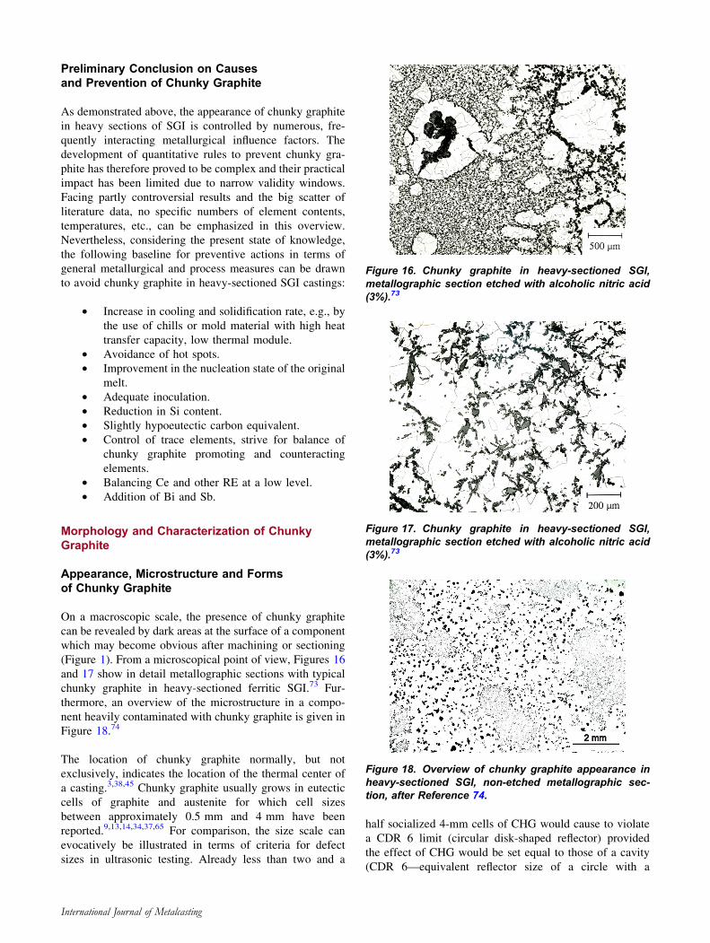
On a macroscopic scale, the presence of chunky graphite
can be revealed by dark areas at the surface of a component
which may become obvious after machining or sectioning
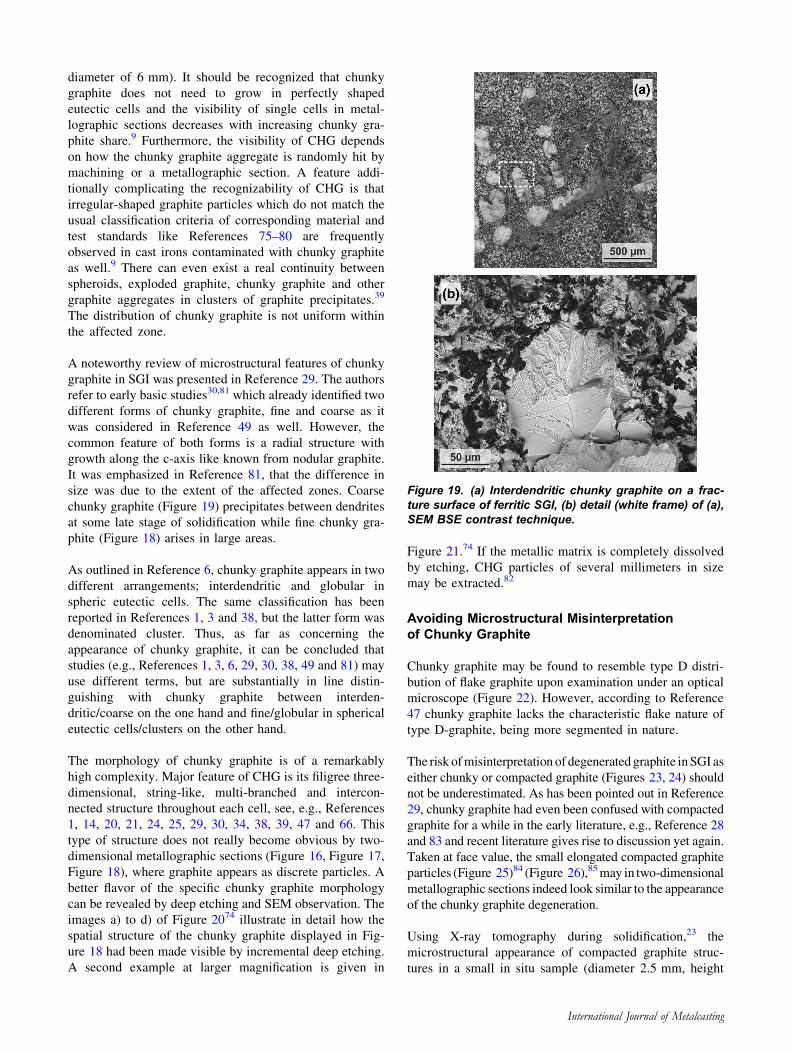
(Figure 1). From a microscopical point of view, Figures 16
and 17 show in detail metallographic sections with typical
chunky graphite in heavy-sectioned ferritic SGI.73 Fur-
thermore, an overview of the microstructure in a compo-
nent heavily contaminated with chunky graphite is given in
Figure 18.74
The location of chunky graphite normally, but not
exclusively, indicates the location of the thermal center of
a casting.3,38,45 Chunky graphite usually grows in eutectic
cells of graphite and austenite for which cell sizes
between approximately 0.5 mm and 4 mm have been
reported.9,13,14,34,37,65 For comparison, the size scale can
evocatively be illustrated in terms of criteria for defect
sizes in ultrasonic testing. Already less than two and a
half socialized 4-mm cells of CHG would cause to violate
a CDR 6 limit (circular disk-shaped reflector) provided
the effect of CHG would be set equal to those of a cavity
(CDR 6—equivalent reflector size of a circle with a
Figure 16. Chunky graphite in heavy-sectioned SGI,metallographic section etched with alcoholic nitric acid(3%).73
Figure 17. Chunky graphite in heavy-sectioned SGI,metallographic section etched with alcoholic nitric acid(3%).73
Figure 18. Overview of chunky graphite appearance inheavy-sectioned SGI, non-etched metallographic sec-tion, after Reference 74.
International Journal of Metalcasting
diameter of 6 mm). It should be recognized that chunky
graphite does not need to grow in perfectly shaped
eutectic cells and the visibility of single cells in metal-
lographic sections decreases with increasing chunky gra-
phite share.9 Furthermore, the visibility of CHG depends
on how the chunky graphite aggregate is randomly hit by
machining or a metallographic section. A feature addi-
tionally complicating the recognizability of CHG is that
irregular-shaped graphite particles which do not match the
usual classification criteria of corresponding material and
test standards like References 75–80 are frequently
observed in cast irons contaminated with chunky graphite
as well.9 There can even exist a real continuity between
spheroids, exploded graphite, chunky graphite and other
graphite aggregates in clusters of graphite precipitates.39
The distribution of chunky graphite is not uniform within
the affected zone.
A noteworthy review of microstructural features of chunky
graphite in SGI was presented in Reference 29. The authors
refer to early basic studies30,81 which already identified two
different forms of chunky graphite, fine and coarse as it
was considered in Reference 49 as well. However, the
common feature of both forms is a radial structure with
growth along the c-axis like known from nodular graphite.
It was emphasized in Reference 81, that the difference in
size was due to the extent of the affected zones. Coarse
chunky graphite (Figure 19) precipitates between dendrites
at some late stage of solidification while fine chunky gra-
phite (Figure 18) arises in large areas.
As outlined in Reference 6, chunky graphite appears in two
different arrangements; interdendritic and globular in
spheric eutectic cells. The same classification has been
reported in References 1, 3 and 38, but the latter form was
denominated cluster. Thus, as far as concerning the
appearance of chunky graphite, it can be concluded that
studies (e.g., References 1, 3, 6, 29, 30, 38, 49 and 81) may
use different terms, but are substantially in line distin-
guishing with chunky graphite between interden-
dritic/coarse on the one hand and fine/globular in spherical
eutectic cells/clusters on the other hand.
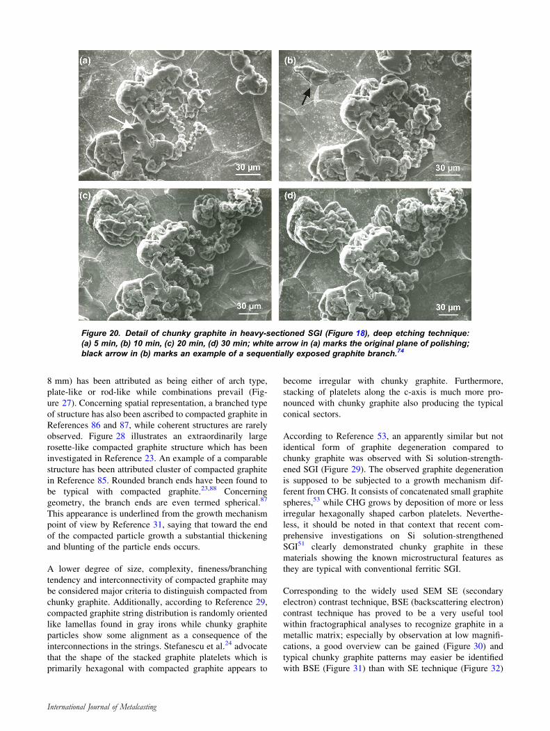
The morphology of chunky graphite is of a remarkably
high complexity. Major feature of CHG is its filigree three-
dimensional, string-like, multi-branched and intercon-
nected structure throughout each cell, see, e.g., References
1, 14, 20, 21, 24, 25, 29, 30, 34, 38, 39, 47 and 66. This
type of structure does not really become obvious by two-
dimensional metallographic sections (Figure 16, Figure 17,
Figure 18), where graphite appears as discrete particles. A
better flavor of the specific chunky graphite morphology
can be revealed by deep etching and SEM observation. The
images a) to d) of Figure 2074 illustrate in detail how the
spatial structure of the chunky graphite displayed in Fig-
ure 18 had been made visible by incremental deep etching.
A second example at larger magnification is given in
Figure 21.74 If the metallic matrix is completely dissolved
by etching, CHG particles of several millimeters in size
may be extracted.82
Avoiding Microstructural Misinterpretationof Chunky Graphite
Chunky graphite may be found to resemble type D distri-
bution of flake graphite upon examination under an optical
microscope (Figure 22). However, according to Reference
47 chunky graphite lacks the characteristic flake nature of
type D-graphite, being more segmented in nature.
The risk ofmisinterpretation of degenerated graphite inSGI as
either chunky or compacted graphite (Figures 23, 24) should
not be underestimated. As has been pointed out in Reference
29, chunky graphite had even been confused with compacted
graphite for a while in the early literature, e.g., Reference 28
and 83 and recent literature gives rise to discussion yet again.
Taken at face value, the small elongated compacted graphite
particles (Figure 25)84 (Figure 26),85may in two-dimensional
metallographic sections indeed look similar to the appearance
of the chunky graphite degeneration.
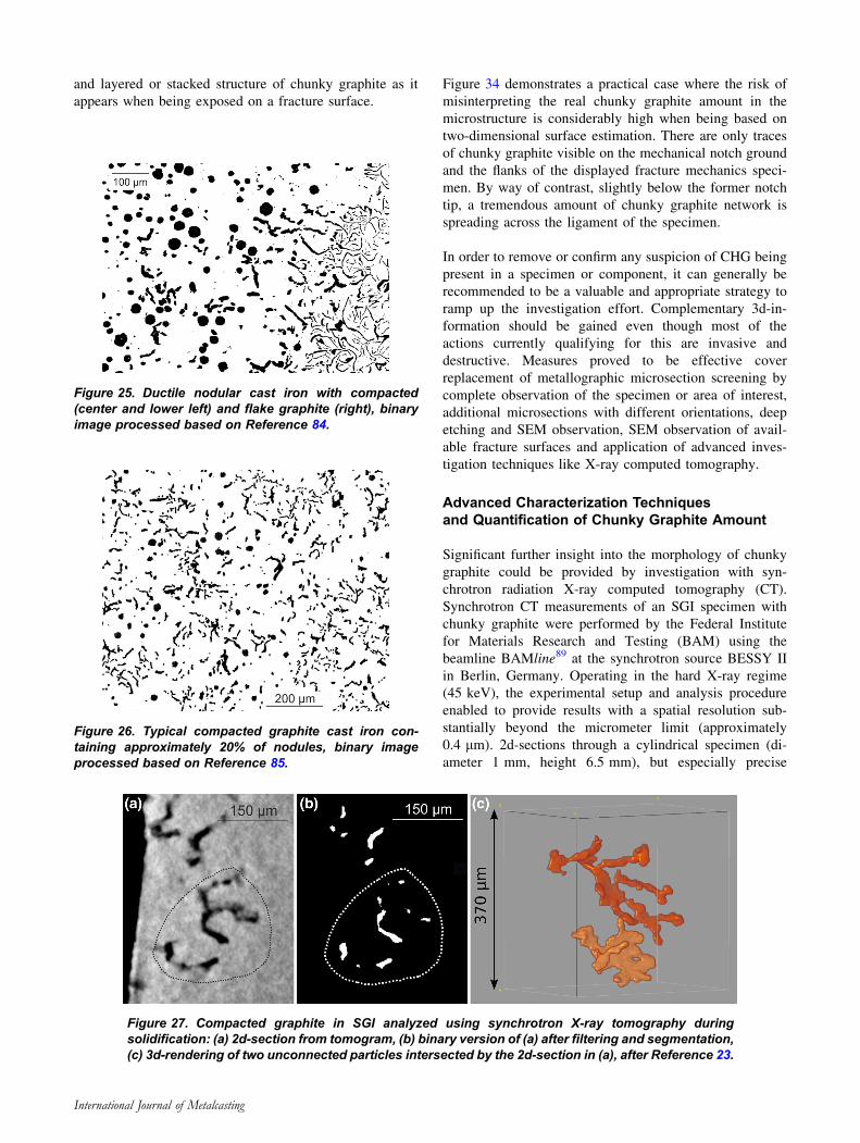
Using X-ray tomography during solidification,23 the
microstructural appearance of compacted graphite struc-
tures in a small in situ sample (diameter 2.5 mm, height
Figure 19. (a) Interdendritic chunky graphite on a frac-ture surface of ferritic SGI, (b) detail (white frame) of (a),SEM BSE contrast technique.
International Journal of Metalcasting
8 mm) has been attributed as being either of arch type,
plate-like or rod-like while combinations prevail (Fig-
ure 27). Concerning spatial representation, a branched type
of structure has also been ascribed to compacted graphite in
References 86 and 87, while coherent structures are rarely
observed. Figure 28 illustrates an extraordinarily large
rosette-like compacted graphite structure which has been
investigated in Reference 23. An example of a comparable
structure has been attributed cluster of compacted graphite
in Reference 85. Rounded branch ends have been found to
be typical with compacted graphite.23,88 Concerning
geometry, the branch ends are even termed spherical.87
This appearance is underlined from the growth mechanism
point of view by Reference 31, saying that toward the end
of the compacted particle growth a substantial thickening
and blunting of the particle ends occurs.
A lower degree of size, complexity, fineness/branching
tendency and interconnectivity of compacted graphite may
be considered major criteria to distinguish compacted from
chunky graphite. Additionally, according to Reference 29,
compacted graphite string distribution is randomly oriented
like lamellas found in gray irons while chunky graphite
particles show some alignment as a consequence of the
interconnections in the strings. Stefanescu et al.24 advocate
that the shape of the stacked graphite platelets which is
primarily hexagonal with compacted graphite appears to
become irregular with chunky graphite. Furthermore,
stacking of platelets along the c-axis is much more pro-
nounced with chunky graphite also producing the typical
conical sectors.
According to Reference 53, an apparently similar but not
identical form of graphite degeneration compared to
chunky graphite was observed with Si solution-strength-
ened SGI (Figure 29). The observed graphite degeneration
is supposed to be subjected to a growth mechanism dif-
ferent from CHG. It consists of concatenated small graphite
spheres,53 while CHG grows by deposition of more or less
irregular hexagonally shaped carbon platelets. Neverthe-
less, it should be noted in that context that recent com-
prehensive investigations on Si solution-strengthened
SGI51 clearly demonstrated chunky graphite in these
materials showing the known microstructural features as
they are typical with conventional ferritic SGI.
Corresponding to the widely used SEM SE (secondary
electron) contrast technique, BSE (backscattering electron)
contrast technique has proved to be a very useful tool
within fractographical analyses to recognize graphite in a
metallic matrix; especially by observation at low magnifi-
cations, a good overview can be gained (Figure 30) and
typical chunky graphite patterns may easier be identified
with BSE (Figure 31) than with SE technique (Figure 32)
Figure 20. Detail of chunky graphite in heavy-sectioned SGI (Figure 18), deep etching technique:(a) 5 min, (b) 10 min, (c) 20 min, (d) 30 min; white arrow in (a) marks the original plane of polishing;black arrow in (b) marks an example of a sequentially exposed graphite branch.74
International Journal of Metalcasting
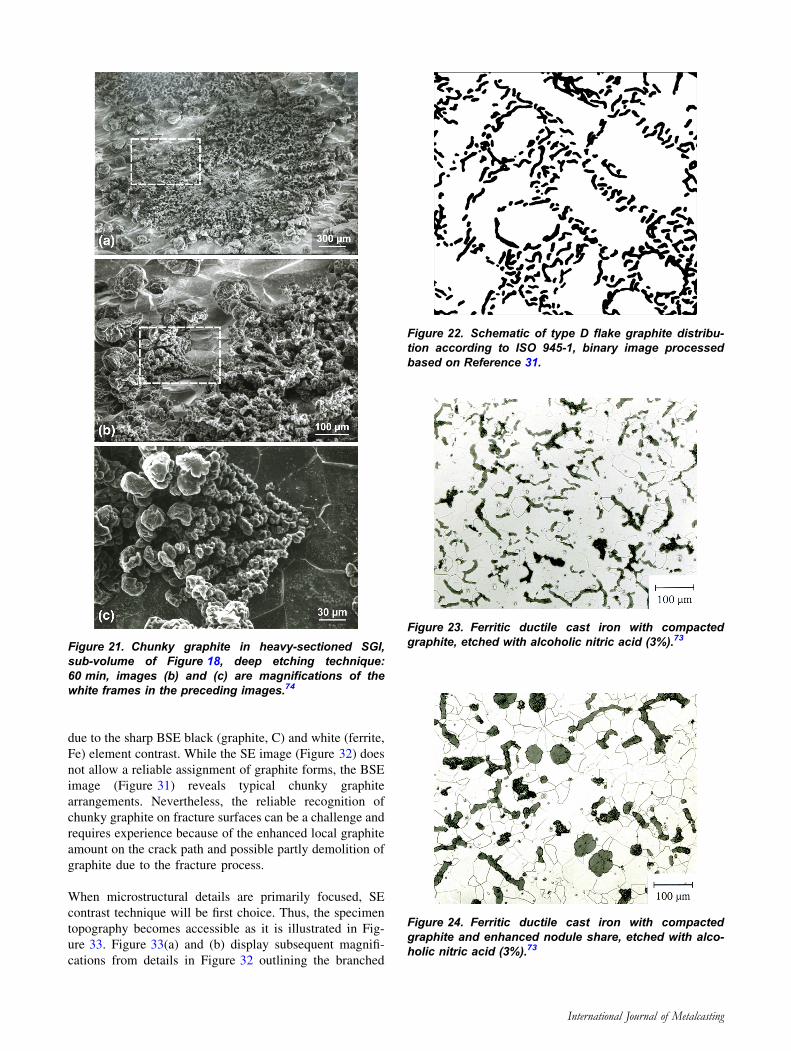
due to the sharp BSE black (graphite, C) and white (ferrite,
Fe) element contrast. While the SE image (Figure 32) does
not allow a reliable assignment of graphite forms, the BSE
image (Figure 31) reveals typical chunky graphite
arrangements. Nevertheless, the reliable recognition of
chunky graphite on fracture surfaces can be a challenge and
requires experience because of the enhanced local graphite
amount on the crack path and possible partly demolition of
graphite due to the fracture process.
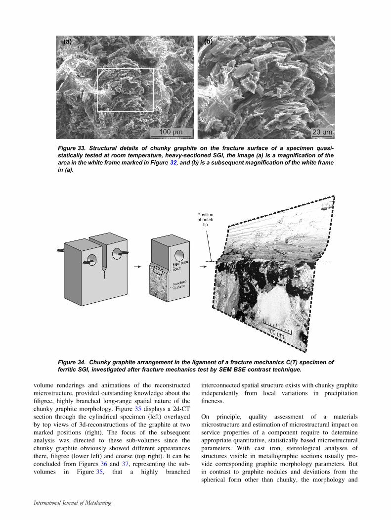
When microstructural details are primarily focused, SE
contrast technique will be first choice. Thus, the specimen
topography becomes accessible as it is illustrated in Fig-
ure 33. Figure 33(a) and (b) display subsequent magnifi-
cations from details in Figure 32 outlining the branched
Figure 21. Chunky graphite in heavy-sectioned SGI,sub-volume of Figure 18, deep etching technique:60 min, images (b) and (c) are magnifications of thewhite frames in the preceding images.74
Figure 22. Schematic of type D flake graphite distribu-tion according to ISO 945-1, binary image processedbased on Reference 31.
Figure 23. Ferritic ductile cast iron with compactedgraphite, etched with alcoholic nitric acid (3%).73
Figure 24. Ferritic ductile cast iron with compactedgraphite and enhanced nodule share, etched with alco-holic nitric acid (3%).73
International Journal of Metalcasting
and layered or stacked structure of chunky graphite as it
appears when being exposed on a fracture surface.
Figure 34 demonstrates a practical case where the risk of
misinterpreting the real chunky graphite amount in the
microstructure is considerably high when being based on
two-dimensional surface estimation. There are only traces
of chunky graphite visible on the mechanical notch ground
and the flanks of the displayed fracture mechanics speci-
men. By way of contrast, slightly below the former notch
tip, a tremendous amount of chunky graphite network is
spreading across the ligament of the specimen.
In order to remove or confirm any suspicion of CHG being
present in a specimen or component, it can generally be
recommended to be a valuable and appropriate strategy to
ramp up the investigation effort. Complementary 3d-in-
formation should be gained even though most of the
actions currently qualifying for this are invasive and
destructive. Measures proved to be effective cover
replacement of metallographic microsection screening by
complete observation of the specimen or area of interest,
additional microsections with different orientations, deep
etching and SEM observation, SEM observation of avail-
able fracture surfaces and application of advanced inves-
tigation techniques like X-ray computed tomography.
Advanced Characterization Techniquesand Quantification of Chunky Graphite Amount
Significant further insight into the morphology of chunky
graphite could be provided by investigation with syn-
chrotron radiation X-ray computed tomography (CT).
Synchrotron CT measurements of an SGI specimen with
chunky graphite were performed by the Federal Institute
for Materials Research and Testing (BAM) using the
beamline BAMline89 at the synchrotron source BESSY II
in Berlin, Germany. Operating in the hard X-ray regime
(45 keV), the experimental setup and analysis procedure
enabled to provide results with a spatial resolution sub-
stantially beyond the micrometer limit (approximately
0.4 lm). 2d-sections through a cylindrical specimen (di-
ameter 1 mm, height 6.5 mm), but especially precise
Figure 25. Ductile nodular cast iron with compacted(center and lower left) and flake graphite (right), binaryimage processed based on Reference 84.
Figure 26. Typical compacted graphite cast iron con-taining approximately 20% of nodules, binary imageprocessed based on Reference 85.
Figure 27. Compacted graphite in SGI analyzed using synchrotron X-ray tomography duringsolidification: (a) 2d-section from tomogram, (b) binary version of (a) after filtering and segmentation,(c) 3d-rendering of two unconnected particles intersected by the 2d-section in (a), after Reference 23.
International Journal of Metalcasting
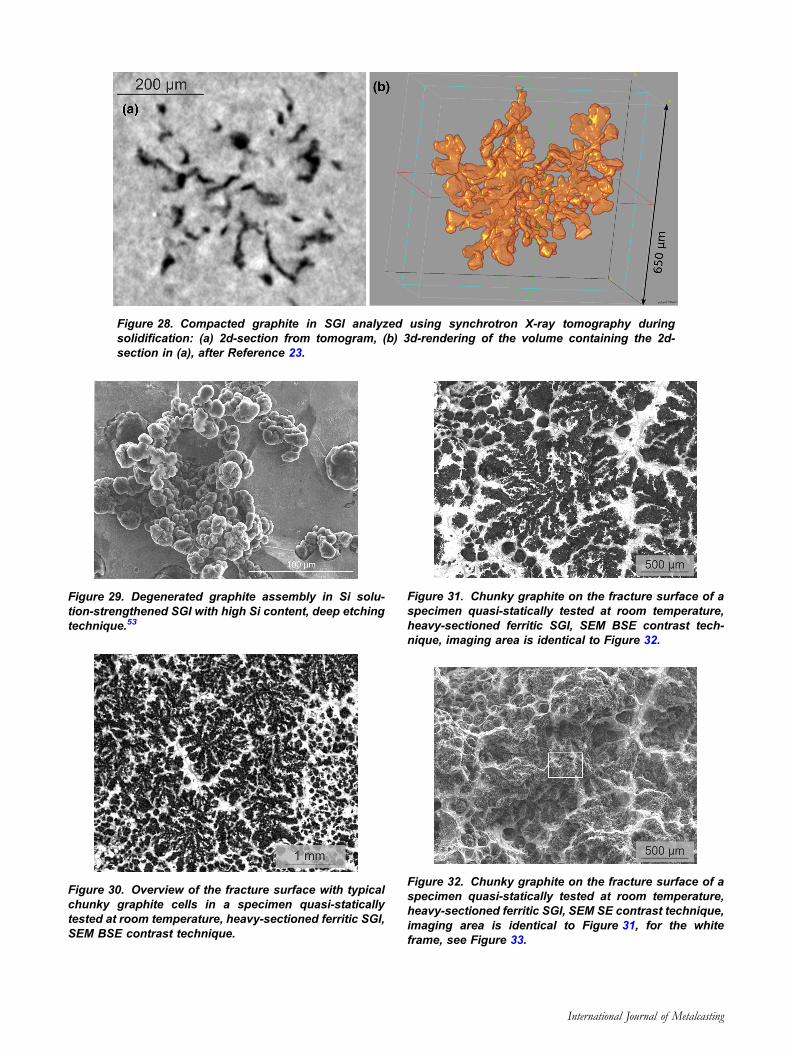
Figure 28. Compacted graphite in SGI analyzed using synchrotron X-ray tomography duringsolidification: (a) 2d-section from tomogram, (b) 3d-rendering of the volume containing the 2d-section in (a), after Reference 23.
Figure 29. Degenerated graphite assembly in Si solu-tion-strengthened SGI with high Si content, deep etchingtechnique.53
Figure 30. Overview of the fracture surface with typicalchunky graphite cells in a specimen quasi-staticallytested at room temperature, heavy-sectioned ferritic SGI,SEM BSE contrast technique.
Figure 31. Chunky graphite on the fracture surface of aspecimen quasi-statically tested at room temperature,heavy-sectioned ferritic SGI, SEM BSE contrast tech-nique, imaging area is identical to Figure 32.
Figure 32. Chunky graphite on the fracture surface of aspecimen quasi-statically tested at room temperature,heavy-sectioned ferritic SGI, SEM SE contrast technique,imaging area is identical to Figure 31, for the whiteframe, see Figure 33.
International Journal of Metalcasting
volume renderings and animations of the reconstructed
microstructure, provided outstanding knowledge about the
filigree, highly branched long-range spatial nature of the
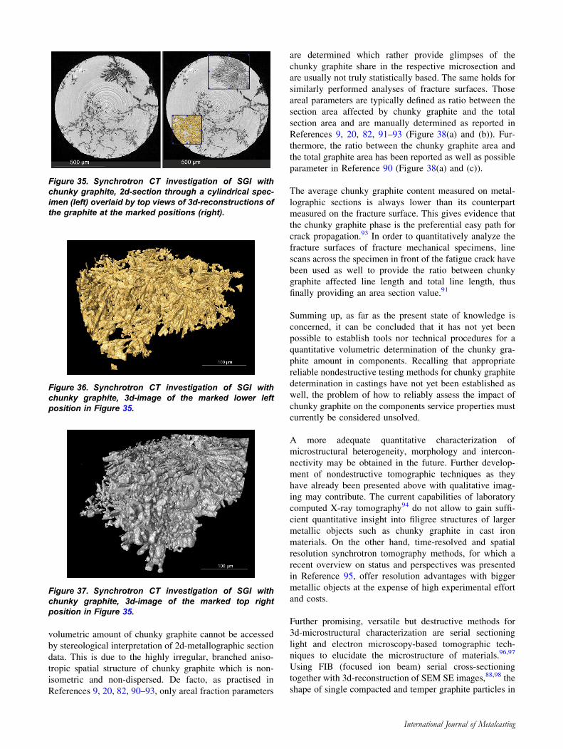
chunky graphite morphology. Figure 35 displays a 2d-CT
section through the cylindrical specimen (left) overlayed
by top views of 3d-reconstructions of the graphite at two
marked positions (right). The focus of the subsequent
analysis was directed to these sub-volumes since the
chunky graphite obviously showed different appearances
there, filigree (lower left) and coarse (top right). It can be
concluded from Figures 36 and 37, representing the sub-
volumes in Figure 35, that a highly branched
interconnected spatial structure exists with chunky graphite
independently from local variations in precipitation
fineness.
On principle, quality assessment of a materials
microstructure and estimation of microstructural impact on
service properties of a component require to determine
appropriate quantitative, statistically based microstructural
parameters. With cast iron, stereological analyses of
structures visible in metallographic sections usually pro-
vide corresponding graphite morphology parameters. But
in contrast to graphite nodules and deviations from the
spherical form other than chunky, the morphology and
Figure 34. Chunky graphite arrangement in the ligament of a fracture mechanics C(T) specimen offerritic SGI, investigated after fracture mechanics test by SEM BSE contrast technique.
Figure 33. Structural details of chunky graphite on the fracture surface of a specimen quasi-statically tested at room temperature, heavy-sectioned SGI, the image (a) is a magnification of thearea in the white frame marked in Figure 32, and (b) is a subsequent magnification of the white framein (a).
International Journal of Metalcasting
volumetric amount of chunky graphite cannot be accessed
by stereological interpretation of 2d-metallographic section
data. This is due to the highly irregular, branched aniso-
tropic spatial structure of chunky graphite which is non-
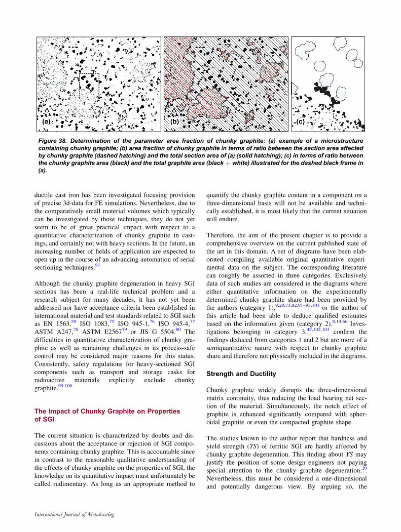
isometric and non-dispersed. De facto, as practised in
References 9, 20, 82, 90–93, only areal fraction parameters
are determined which rather provide glimpses of the
chunky graphite share in the respective microsection and
are usually not truly statistically based. The same holds for
similarly performed analyses of fracture surfaces. Those
areal parameters are typically defined as ratio between the
section area affected by chunky graphite and the total
section area and are manually determined as reported in
References 9, 20, 82, 91–93 (Figure 38(a) and (b)). Fur-
thermore, the ratio between the chunky graphite area and
the total graphite area has been reported as well as possible
parameter in Reference 90 (Figure 38(a) and (c)).
The average chunky graphite content measured on metal-
lographic sections is always lower than its counterpart
measured on the fracture surface. This gives evidence that
the chunky graphite phase is the preferential easy path for
crack propagation.93 In order to quantitatively analyze the
fracture surfaces of fracture mechanical specimens, line
scans across the specimen in front of the fatigue crack have
been used as well to provide the ratio between chunky
graphite affected line length and total line length, thus
finally providing an area section value.91
Summing up, as far as the present state of knowledge is
concerned, it can be concluded that it has not yet been
possible to establish tools nor technical procedures for a
quantitative volumetric determination of the chunky gra-
phite amount in components. Recalling that appropriate
reliable nondestructive testing methods for chunky graphite
determination in castings have not yet been established as
well, the problem of how to reliably assess the impact of
chunky graphite on the components service properties must
currently be considered unsolved.
A more adequate quantitative characterization of
microstructural heterogeneity, morphology and intercon-
nectivity may be obtained in the future. Further develop-
ment of nondestructive tomographic techniques as they
have already been presented above with qualitative imag-
ing may contribute. The current capabilities of laboratory
computed X-ray tomography94 do not allow to gain suffi-
cient quantitative insight into filigree structures of larger
metallic objects such as chunky graphite in cast iron
materials. On the other hand, time-resolved and spatial
resolution synchrotron tomography methods, for which a
recent overview on status and perspectives was presented
in Reference 95, offer resolution advantages with bigger
metallic objects at the expense of high experimental effort
and costs.
Further promising, versatile but destructive methods for
3d-microstructural characterization are serial sectioning
light and electron microscopy-based tomographic tech-
niques to elucidate the microstructure of materials.96,97
Using FIB (focused ion beam) serial cross-sectioning
together with 3d-reconstruction of SEM SE images,88,98 the
shape of single compacted and temper graphite particles in
Figure 35. Synchrotron CT investigation of SGI withchunky graphite, 2d-section through a cylindrical spec-imen (left) overlaid by top views of 3d-reconstructions ofthe graphite at the marked positions (right).
Figure 36. Synchrotron CT investigation of SGI withchunky graphite, 3d-image of the marked lower leftposition in Figure 35.
Figure 37. Synchrotron CT investigation of SGI withchunky graphite, 3d-image of the marked top rightposition in Figure 35.
International Journal of Metalcasting
ductile cast iron has been investigated focusing provision
of precise 3d-data for FE simulations. Nevertheless, due to
the comparatively small material volumes which typically
can be investigated by those techniques, they do not yet
seem to be of great practical impact with respect to a
quantitative characterization of chunky graphite in cast-
ings, and certainly not with heavy sections. In the future, an
increasing number of fields of application are expected to
open up in the course of an advancing automation of serial
sectioning techniques.97
Although the chunky graphite degeneration in heavy SGI
sections has been a real-life technical problem and a
research subject for many decades, it has not yet been
addressed nor have acceptance criteria been established in
international material and test standards related to SGI such
as EN 1563,50 ISO 1083,75 ISO 945-1,76 ISO 945-4,77
ASTM A247,78 ASTM E256779 or JIS G 5504.80 The
difficulties in quantitative characterization of chunky gra-
phite as well as remaining challenges in its process-safe
control may be considered major reasons for this status.
Consistently, safety regulations for heavy-sectioned SGI
components such as transport and storage casks for
radioactive materials explicitly exclude chunky
graphite.99,100
The Impact of Chunky Graphite on Propertiesof SGI
The current situation is characterized by doubts and dis-
cussions about the acceptance or rejection of SGI compo-
nents containing chunky graphite. This is accountable since
in contrast to the reasonable qualitative understanding of
the effects of chunky graphite on the properties of SGI, the
knowledge on its quantitative impact must unfortunately be
called rudimentary. As long as an appropriate method to
quantify the chunky graphite content in a component on a
three-dimensional basis will not be available and techni-
cally established, it is most likely that the current situation
will endure.
Therefore, the aim of the present chapter is to provide a
comprehensive overview on the current published state of
the art in this domain. A set of diagrams have been elab-
orated compiling available original quantitative experi-
mental data on the subject. The corresponding literature
can roughly be assorted in three categories. Exclusively
data of such studies are considered in the diagrams where
either quantitative information on the experimentally
determined chunky graphite share had been provided by
the authors (category 1),9,20,73,82,91–93,101 or the author of
this article had been able to deduce qualified estimates
based on the information given (category 2).8,14,66 Inves-
tigations belonging to category 3,47,102,103 confirm the
findings deduced from categories 1 and 2 but are more of a
semiquantitative nature with respect to chunky graphite
share and therefore not physically included in the diagrams.
Strength and Ductility
Chunky graphite widely disrupts the three-dimensional
matrix continuity, thus reducing the load bearing net sec-
tion of the material. Simultaneously, the notch effect of
graphite is enhanced significantly compared with spher-
oidal graphite or even the compacted graphite shape.
The studies known to the author report that hardness and
yield strength (YS) of ferritic SGI are hardly affected by
chunky graphite degeneration. This finding about YS may
justify the position of some design engineers not paying
special attention to the chunky graphite degeneration.20
Nevertheless, this must be considered a one-dimensional
and potentially dangerous view. By arguing so, the
Figure 38. Determination of the parameter area fraction of chunky graphite: (a) example of a microstructurecontaining chunky graphite; (b) area fraction of chunky graphite in terms of ratio between the section area affectedby chunky graphite (dashed hatching) and the total section area of (a) (solid hatching); (c) in terms of ratio betweenthe chunky graphite area (black) and the total graphite area (black ? white) illustrated for the dashed black frame in(a).
International Journal of Metalcasting
tremendous detrimental impact of chunky graphite on
ductility, ultimate tensile strength (UTS), toughness and
fatigue limit, which are important structural safety factors,
is neglected.
Figures 39 and 40 conflate information on the correlation
between the chunky graphite share and mechanical prop-
erties of ferritic SGI. All data are for conventional, low Si
ferritic EN-GJS-400 materials except of the results in
References 9 and 82 where silicon solid solution-
strengthened SGI with 3.2–3.5% of Si have been
investigated.
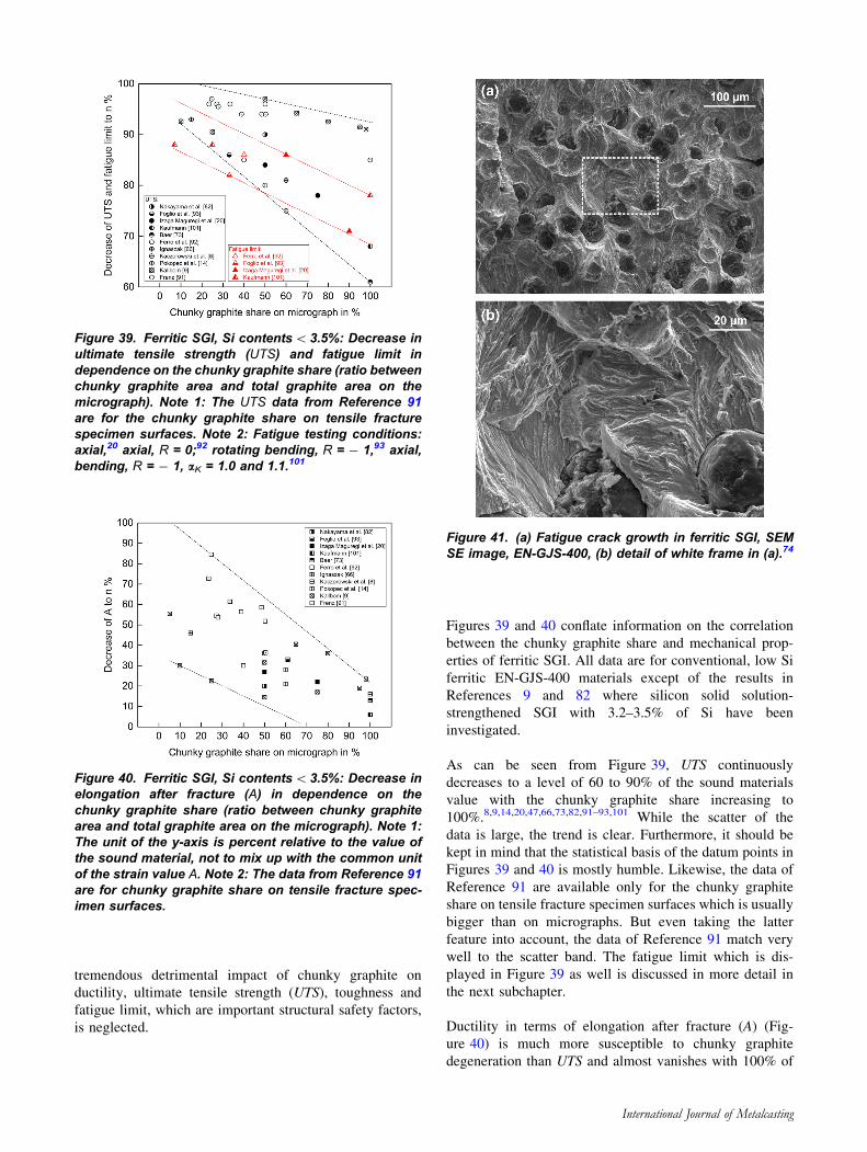
As can be seen from Figure 39, UTS continuously
decreases to a level of 60 to 90% of the sound materials
value with the chunky graphite share increasing to
100%.8,9,14,20,47,66,73,82,91–93,101 While the scatter of the
data is large, the trend is clear. Furthermore, it should be
kept in mind that the statistical basis of the datum points in
Figures 39 and 40 is mostly humble. Likewise, the data of
Reference 91 are available only for the chunky graphite
share on tensile fracture specimen surfaces which is usually
bigger than on micrographs. But even taking the latter
feature into account, the data of Reference 91 match very
well to the scatter band. The fatigue limit which is dis-
played in Figure 39 as well is discussed in more detail in
the next subchapter.
Ductility in terms of elongation after fracture (A) (Fig-
ure 40) is much more susceptible to chunky graphite
degeneration than UTS and almost vanishes with 100% of
Figure 39. Ferritic SGI, Si contents\3.5%: Decrease inultimate tensile strength (UTS) and fatigue limit independence on the chunky graphite share (ratio betweenchunky graphite area and total graphite area on themicrograph). Note 1: The UTS data from Reference 91are for the chunky graphite share on tensile fracturespecimen surfaces. Note 2: Fatigue testing conditions:axial,20 axial, R = 0;92 rotating bending, R = - 1,93 axial,bending, R = - 1, aK = 1.0 and 1.1.101
Figure 40. Ferritic SGI, Si contents\3.5%: Decrease inelongation after fracture (A) in dependence on thechunky graphite share (ratio between chunky graphitearea and total graphite area on the micrograph). Note 1:The unit of the y-axis is percent relative to the value ofthe sound material, not to mix up with the common unitof the strain value A. Note 2: The data from Reference 91are for chunky graphite share on tensile fracture spec-imen surfaces.
Figure 41. (a) Fatigue crack growth in ferritic SGI, SEMSE image, EN-GJS-400, (b) detail of white frame in (a).74
International Journal of Metalcasting
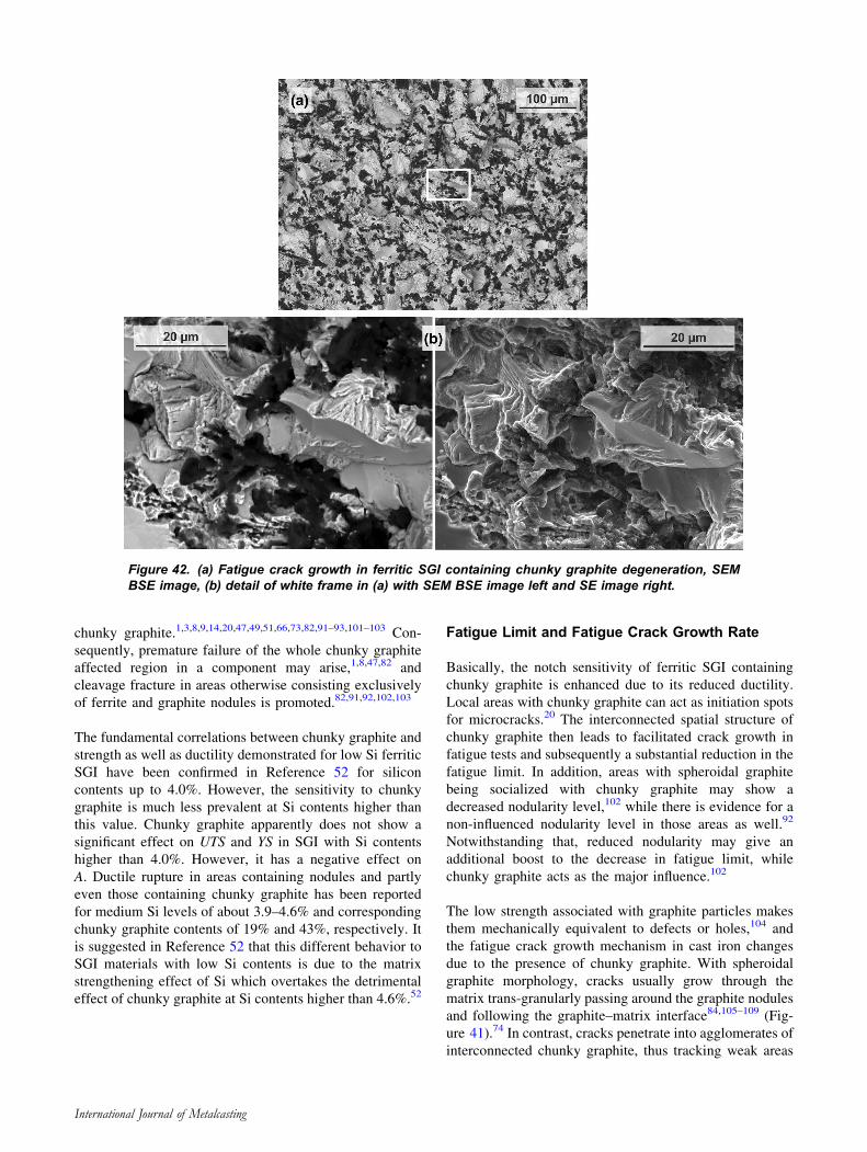
chunky graphite.1,3,8,9,14,20,47,49,51,66,73,82,91–93,101–103 Con-
sequently, premature failure of the whole chunky graphite
affected region in a component may arise,1,8,47,82 and
cleavage fracture in areas otherwise consisting exclusively
of ferrite and graphite nodules is promoted.82,91,92,102,103
The fundamental correlations between chunky graphite and
strength as well as ductility demonstrated for low Si ferritic
SGI have been confirmed in Reference 52 for silicon
contents up to 4.0%. However, the sensitivity to chunky
graphite is much less prevalent at Si contents higher than
this value. Chunky graphite apparently does not show a
significant effect on UTS and YS in SGI with Si contents
higher than 4.0%. However, it has a negative effect on
A. Ductile rupture in areas containing nodules and partly
even those containing chunky graphite has been reported
for medium Si levels of about 3.9–4.6% and corresponding
chunky graphite contents of 19% and 43%, respectively. It
is suggested in Reference 52 that this different behavior to
SGI materials with low Si contents is due to the matrix
strengthening effect of Si which overtakes the detrimental
effect of chunky graphite at Si contents higher than 4.6%.52
Fatigue Limit and Fatigue Crack Growth Rate
Basically, the notch sensitivity of ferritic SGI containing
chunky graphite is enhanced due to its reduced ductility.
Local areas with chunky graphite can act as initiation spots
for microcracks.20 The interconnected spatial structure of
chunky graphite then leads to facilitated crack growth in
fatigue tests and subsequently a substantial reduction in the
fatigue limit. In addition, areas with spheroidal graphite
being socialized with chunky graphite may show a
decreased nodularity level,102 while there is evidence for a
non-influenced nodularity level in those areas as well.92
Notwithstanding that, reduced nodularity may give an
additional boost to the decrease in fatigue limit, while
chunky graphite acts as the major influence.102
The low strength associated with graphite particles makes
them mechanically equivalent to defects or holes,104 and
the fatigue crack growth mechanism in cast iron changes
due to the presence of chunky graphite. With spheroidal
graphite morphology, cracks usually grow through the
matrix trans-granularly passing around the graphite nodules
and following the graphite–matrix interface84,105–109 (Fig-
ure 41).74 In contrast, cracks penetrate into agglomerates of
interconnected chunky graphite, thus tracking weak areas
Figure 42. (a) Fatigue crack growth in ferritic SGI containing chunky graphite degeneration, SEMBSE image, (b) detail of white frame in (a) with SEM BSE image left and SE image right.
International Journal of Metalcasting
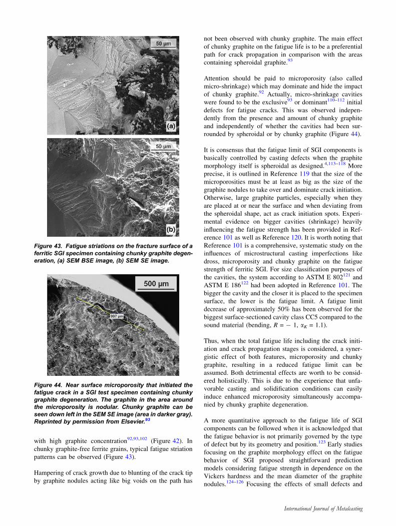
with high graphite concentration92,93,102 (Figure 42). In
chunky graphite-free ferrite grains, typical fatigue striation
patterns can be observed (Figure 43).
Hampering of crack growth due to blunting of the crack tip
by graphite nodules acting like big voids on the path has
not been observed with chunky graphite. The main effect
of chunky graphite on the fatigue life is to be a preferential
path for crack propagation in comparison with the areas
containing spheroidal graphite.93
Attention should be paid to microporosity (also called
micro-shrinkage) which may dominate and hide the impact
of chunky graphite.92 Actually, micro-shrinkage cavities
were found to be the exclusive93 or dominant110–112 initial
defects for fatigue cracks. This was observed indepen-
dently from the presence and amount of chunky graphite
and independently of whether the cavities had been sur-
rounded by spheroidal or by chunky graphite (Figure 44).
It is consensus that the fatigue limit of SGI components is
basically controlled by casting defects when the graphite
morphology itself is spheroidal as designed.4,113–118 More
precise, it is outlined in Reference 119 that the size of the
microporosities must be at least as big as the size of the
graphite nodules to take over and dominate crack initiation.
Otherwise, large graphite particles, especially when they
are placed at or near the surface and when deviating from
the spheroidal shape, act as crack initiation spots. Experi-
mental evidence on bigger cavities (shrinkage) heavily
influencing the fatigue strength has been provided in Ref-
erence 101 as well as Reference 120. It is worth noting that
Reference 101 is a comprehensive, systematic study on the
influences of microstructural casting imperfections like
dross, microporosity and chunky graphite on the fatigue
strength of ferritic SGI. For size classification purposes of
the cavities, the system according to ASTM E 802121 and
ASTM E 186122 had been adopted in Reference 101. The
bigger the cavity and the closer it is placed to the specimen
surface, the lower is the fatigue limit. A fatigue limit
decrease of approximately 50% has been observed for the
biggest surface-sectioned cavity class CC5 compared to the
sound material (bending, R = - 1, aK = 1.1).
Thus, when the total fatigue life including the crack initi-
ation and crack propagation stages is considered, a syner-
gistic effect of both features, microporosity and chunky
graphite, resulting in a reduced fatigue limit can be
assumed. Both detrimental effects are worth to be consid-
ered holistically. This is due to the experience that unfa-
vorable casting and solidification conditions can easily
induce enhanced microporosity simultaneously accompa-
nied by chunky graphite degeneration.
A more quantitative approach to the fatigue life of SGI
components can be followed when it is acknowledged that
the fatigue behavior is not primarily governed by the type
of defect but by its geometry and position.123 Early studies
focusing on the graphite morphology effect on the fatigue
behavior of SGI proposed straightforward prediction
models considering fatigue strength in dependence on the
Vickers hardness and the mean diameter of the graphite
nodules.124–126 Focusing the effects of small defects and
Figure 43. Fatigue striations on the fracture surface of aferritic SGI specimen containing chunky graphite degen-eration, (a) SEM BSE image, (b) SEM SE image.
Figure 44. Near surface microporosity that initiated thefatigue crack in a SGI test specimen containing chunkygraphite degeneration. The graphite in the area aroundthe microporosity is nodular. Chunky graphite can beseen down left in the SEM SE image (area in darker gray).Reprinted by permission from Elsevier.93
International Journal of Metalcasting
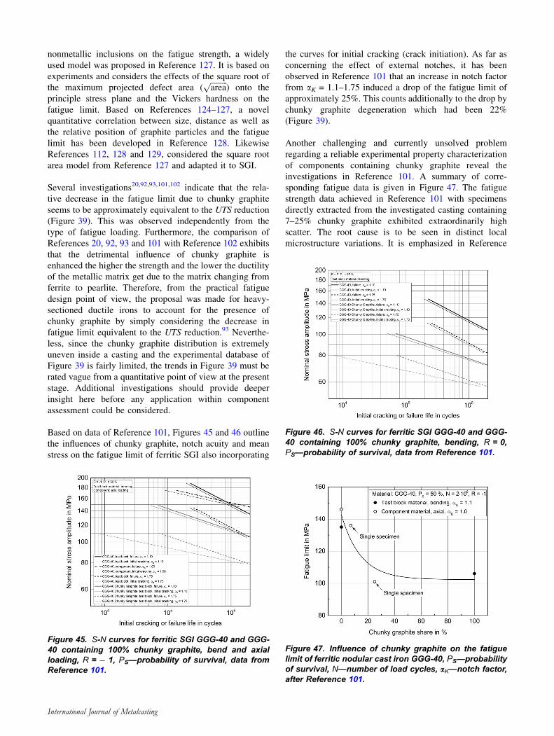
nonmetallic inclusions on the fatigue strength, a widely
used model was proposed in Reference 127. It is based on
experiments and considers the effects of the square root of
the maximum projected defect area (ffiffiffiffiffiffiffiffiffiarea
p) onto the
principle stress plane and the Vickers hardness on the
fatigue limit. Based on References 124–127, a novel
quantitative correlation between size, distance as well as
the relative position of graphite particles and the fatigue
limit has been developed in Reference 128. Likewise
References 112, 128 and 129, considered the square root
area model from Reference 127 and adapted it to SGI.
Several investigations20,92,93,101,102 indicate that the rela-
tive decrease in the fatigue limit due to chunky graphite
seems to be approximately equivalent to the UTS reduction
(Figure 39). This was observed independently from the
type of fatigue loading. Furthermore, the comparison of
References 20, 92, 93 and 101 with Reference 102 exhibits
that the detrimental influence of chunky graphite is
enhanced the higher the strength and the lower the ductility
of the metallic matrix get due to the matrix changing from
ferrite to pearlite. Therefore, from the practical fatigue
design point of view, the proposal was made for heavy-
sectioned ductile irons to account for the presence of
chunky graphite by simply considering the decrease in
fatigue limit equivalent to the UTS reduction.93 Neverthe-
less, since the chunky graphite distribution is extremely
uneven inside a casting and the experimental database of
Figure 39 is fairly limited, the trends in Figure 39 must be
rated vague from a quantitative point of view at the present
stage. Additional investigations should provide deeper
insight here before any application within component
assessment could be considered.
Based on data of Reference 101, Figures 45 and 46 outline
the influences of chunky graphite, notch acuity and mean
stress on the fatigue limit of ferritic SGI also incorporating
the curves for initial cracking (crack initiation). As far as
concerning the effect of external notches, it has been
observed in Reference 101 that an increase in notch factor
from aK = 1.1–1.75 induced a drop of the fatigue limit of
approximately 25%. This counts additionally to the drop by
chunky graphite degeneration which had been 22%
(Figure 39).
Another challenging and currently unsolved problem
regarding a reliable experimental property characterization
of components containing chunky graphite reveal the
investigations in Reference 101. A summary of corre-
sponding fatigue data is given in Figure 47. The fatigue
strength data achieved in Reference 101 with specimens
directly extracted from the investigated casting containing
7–25% chunky graphite exhibited extraordinarily high
scatter. The root cause is to be seen in distinct local
microstructure variations. It is emphasized in Reference
Figure 45. S-N curves for ferritic SGI GGG-40 and GGG-40 containing 100% chunky graphite, bend and axialloading, R = - 1, PS—probability of survival, data fromReference 101.
Figure 46. S-N curves for ferritic SGI GGG-40 and GGG-40 containing 100% chunky graphite, bending, R = 0,PS—probability of survival, data from Reference 101.
Figure 47. Influence of chunky graphite on the fatiguelimit of ferritic nodular cast iron GGG-40, PS—probabilityof survival, N—number of load cycles, aK—notch factor,after Reference 101.
International Journal of Metalcasting
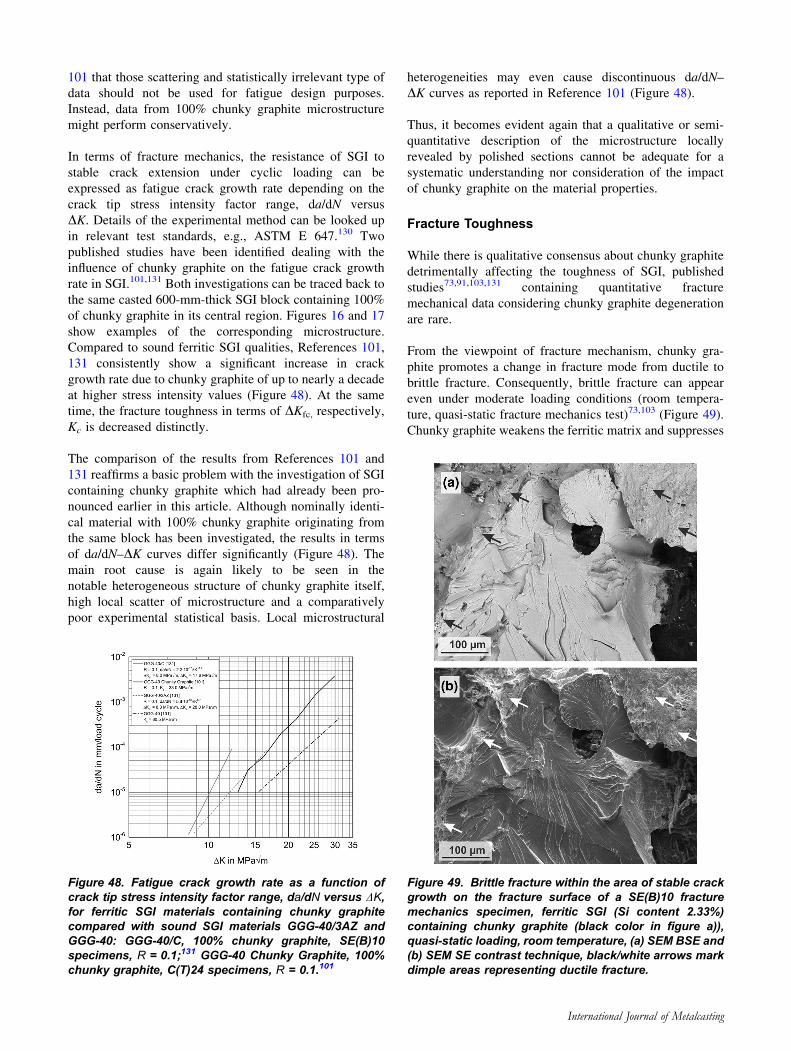
101 that those scattering and statistically irrelevant type of
data should not be used for fatigue design purposes.
Instead, data from 100% chunky graphite microstructure
might perform conservatively.
In terms of fracture mechanics, the resistance of SGI to
stable crack extension under cyclic loading can be
expressed as fatigue crack growth rate depending on the
crack tip stress intensity factor range, da/dN versus
DK. Details of the experimental method can be looked up
in relevant test standards, e.g., ASTM E 647.130 Two
published studies have been identified dealing with the
influence of chunky graphite on the fatigue crack growth
rate in SGI.101,131 Both investigations can be traced back to
the same casted 600-mm-thick SGI block containing 100%
of chunky graphite in its central region. Figures 16 and 17
show examples of the corresponding microstructure.
Compared to sound ferritic SGI qualities, References 101,
131 consistently show a significant increase in crack
growth rate due to chunky graphite of up to nearly a decade
at higher stress intensity values (Figure 48). At the same
time, the fracture toughness in terms of DKfc, respectively,
Kc is decreased distinctly.
The comparison of the results from References 101 and
131 reaffirms a basic problem with the investigation of SGI
containing chunky graphite which had already been pro-
nounced earlier in this article. Although nominally identi-
cal material with 100% chunky graphite originating from
the same block has been investigated, the results in terms
of da/dN–DK curves differ significantly (Figure 48). The
main root cause is again likely to be seen in the
notable heterogeneous structure of chunky graphite itself,
high local scatter of microstructure and a comparatively
poor experimental statistical basis. Local microstructural
heterogeneities may even cause discontinuous da/dN–
DK curves as reported in Reference 101 (Figure 48).
Thus, it becomes evident again that a qualitative or semi-
quantitative description of the microstructure locally
revealed by polished sections cannot be adequate for a
systematic understanding nor consideration of the impact
of chunky graphite on the material properties.
Fracture Toughness
While there is qualitative consensus about chunky graphite
detrimentally affecting the toughness of SGI, published
studies73,91,103,131 containing quantitative fracture
mechanical data considering chunky graphite degeneration
are rare.
From the viewpoint of fracture mechanism, chunky gra-
phite promotes a change in fracture mode from ductile to
brittle fracture. Consequently, brittle fracture can appear
even under moderate loading conditions (room tempera-
ture, quasi-static fracture mechanics test)73,103 (Figure 49).
Chunky graphite weakens the ferritic matrix and suppresses
Figure 48. Fatigue crack growth rate as a function ofcrack tip stress intensity factor range, da/dN versus DK,for ferritic SGI materials containing chunky graphitecompared with sound SGI materials GGG-40/3AZ andGGG-40: GGG-40/C, 100% chunky graphite, SE(B)10specimens, R = 0.1;131 GGG-40 Chunky Graphite, 100%chunky graphite, C(T)24 specimens, R = 0.1.101
Figure 49. Brittle fracture within the area of stable crackgrowth on the fracture surface of a SE(B)10 fracturemechanics specimen, ferritic SGI (Si content 2.33%)containing chunky graphite (black color in figure a)),quasi-static loading, room temperature, (a) SEM BSE and(b) SEM SE contrast technique, black/white arrows markdimple areas representing ductile fracture.
International Journal of Metalcasting
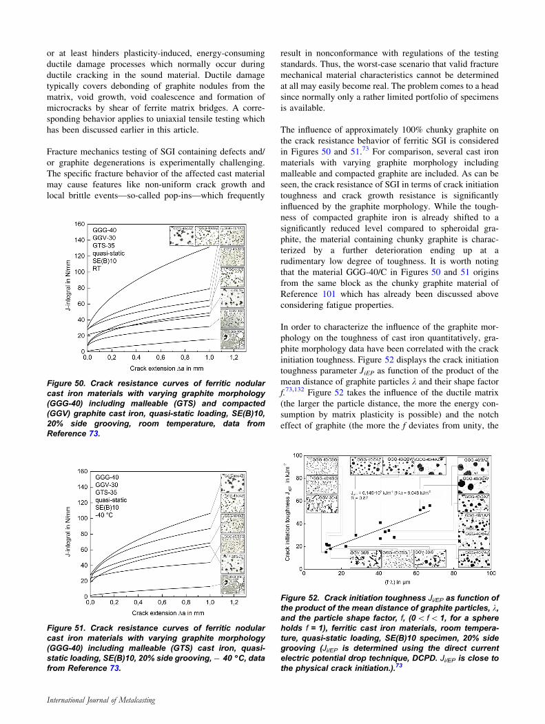
or at least hinders plasticity-induced, energy-consuming
ductile damage processes which normally occur during
ductile cracking in the sound material. Ductile damage
typically covers debonding of graphite nodules from the
matrix, void growth, void coalescence and formation of
microcracks by shear of ferrite matrix bridges. A corre-
sponding behavior applies to uniaxial tensile testing which
has been discussed earlier in this article.
Fracture mechanics testing of SGI containing defects and/
or graphite degenerations is experimentally challenging.
The specific fracture behavior of the affected cast material
may cause features like non-uniform crack growth and
local brittle events—so-called pop-ins—which frequently
result in nonconformance with regulations of the testing
standards. Thus, the worst-case scenario that valid fracture
mechanical material characteristics cannot be determined
at all may easily become real. The problem comes to a head
since normally only a rather limited portfolio of specimens
is available.
The influence of approximately 100% chunky graphite on
the crack resistance behavior of ferritic SGI is considered
in Figures 50 and 51.73 For comparison, several cast iron
materials with varying graphite morphology including
malleable and compacted graphite are included. As can be
seen, the crack resistance of SGI in terms of crack initiation
toughness and crack growth resistance is significantly
influenced by the graphite morphology. While the tough-
ness of compacted graphite iron is already shifted to a
significantly reduced level compared to spheroidal gra-
phite, the material containing chunky graphite is charac-
terized by a further deterioration ending up at a
rudimentary low degree of toughness. It is worth noting
that the material GGG-40/C in Figures 50 and 51 origins
from the same block as the chunky graphite material of
Reference 101 which has already been discussed above
considering fatigue properties.
In order to characterize the influence of the graphite mor-
phology on the toughness of cast iron quantitatively, gra-
phite morphology data have been correlated with the crack
initiation toughness. Figure 52 displays the crack initiation
toughness parameter JiEP as function of the product of the
mean distance of graphite particles k and their shape factor
f.73,132 Figure 52 takes the influence of the ductile matrix
(the larger the particle distance, the more the energy con-
sumption by matrix plasticity is possible) and the notch
effect of graphite (the more the f deviates from unity, the
Figure 50. Crack resistance curves of ferritic nodularcast iron materials with varying graphite morphology(GGG-40) including malleable (GTS) and compacted(GGV) graphite cast iron, quasi-static loading, SE(B)10,20% side grooving, room temperature, data fromReference 73.
Figure 51. Crack resistance curves of ferritic nodularcast iron materials with varying graphite morphology(GGG-40) including malleable (GTS) cast iron, quasi-static loading, SE(B)10, 20% side grooving, - 40 �C, datafrom Reference 73.
Figure 52. Crack initiation toughness Ji/EP as function ofthe product of the mean distance of graphite particles, k,and the particle shape factor, f, (0\ f\1, for a sphereholds f = 1), ferritic cast iron materials, room tempera-ture, quasi-static loading, SE(B)10 specimen, 20% sidegrooving (Ji/EP is determined using the direct currentelectric potential drop technique, DCPD. Ji/EP is close tothe physical crack initiation.).73
International Journal of Metalcasting
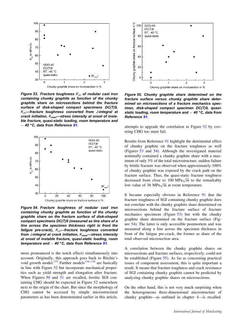
more pronounced is the notch effect) simultaneously into
account. Originally, this approach goes back to Ritchie’s
void growth model.133 Further models134–136 are basically
in line with Figure 52 but incorporate mechanical proper-
ties such as yield strength and elongation after fracture.
When Figures 50 and 51 are recalled, ferritic SGI con-
taining CHG should be expected in Figure 52 somewhere
next to the origin of the chart. But since the morphology of
CHG cannot be accessed by simple microstructural
parameters as has been demonstrated earlier in this article,
attempts to upgrade the correlation in Figure 52 by cov-
ering CHG too must fail.
Results from Reference 91 highlight the detrimental effect
of chunky graphite on the fracture toughness as well
(Figures 53 and 54). Although the investigated material
nominally contained a chunky graphite share with a max-
imum of only 3% of the total microstructure, sudden failure
by brittle fracture was observed when approximately 100%
of chunky graphite was exposed by the crack path on the
fracture surface. Thus, the quasi-static fracture toughness
decreased from close to 100 MPaffiffiffiffim
pto the remarkably
low value of 36 MPaffiffiffiffim
pat room temperature.
It became especially obvious in Reference 91 that the
fracture toughness of SGI containing chunky graphite does
not correlate with the chunky graphite share determined on
microsections behind the fracture surface of fracture
mechanics specimens (Figure 53) but with the chunky
graphite share determined on the fracture surface (Fig-
ure 54). The latter is only accessible postmortem and was
measured along a line across the specimen thickness in
front of the fatigue pre-crack, the former as share of the
total observed microsection area.
A correlation between the chunky graphite shares on
microsections and fracture surfaces, respectively, could not
be established (Figure 55). As far as concerning practical
issues of component assessment, this is quite important a
result. It means that fracture toughness and crack resistance
of SGI containing chunky graphite cannot be predicted by
analyzing chunky graphite shares on microsections.
On the other hand, this is not very much surprising when
the heterogeneous three-dimensional microstructure of
chunky graphite—as outlined in chapter 4—is recalled.
Figure 53. Fracture toughness KJc of nodular cast ironcontaining chunky graphite as function of the chunkygraphite share on microsections behind the fracturesurface of disk-shaped compact specimens DC(T)9,KJc—fracture toughness converted from J-integral atcrack initiation, Kmax—stress intensity at onset of insta-ble fracture, quasi-static loading, room temperature and- 40 �C, data from Reference 91.
Figure 54. Fracture toughness of nodular cast ironcontaining chunky graphite as function of the chunkygraphite share on the fracture surface of disk-shapedcompact specimens DC(T)9 (measured as line share of aline across the specimen thickness right in front thefatigue pre-crack), KJc—fracture toughness convertedfrom J-integral at crack initiation, Kmax—stress intensityat onset of instable fracture, quasi-static loading, roomtemperature and - 40 �C, data from Reference 91.
Figure 55. Chunky graphite share determined on thefracture surface versus chunky graphite share deter-mined on microsections of a fracture mechanics spec-imen, disk-shaped compact specimen DC(T)9, quasi-static loading, room temperature and - 40 �C, data fromReference 91.
International Journal of Metalcasting
The achievable fracture toughness is essentially governed
by the chunky graphite configuration which is randomly
locally present in the ligament of the specimen or the
position of interest in the component, e.g., Figure 34.
While fracture mechanics specimens feature a mechanical
pre-notch and mostly side grooves, tensile specimens are
characterized by a smooth and quite large, elongated test
section subjected to a uniform stress state. Therefore, with
respect to the maximally stressed material volume, the
fracture mechanics specimen is much more locally focused
than a tensile specimen and thus producing bigger scatter
of test results.
Summary
The following overall picture of chunky graphite in ferritic
SGI emerges when the current published state of knowl-
edge is briefly summarized.
Although several theories on the formation and growth of
chunky graphite in SGI have been proposed, a universal,
generally accepted explanation has not yet been estab-
lished. Considering the present state of knowledge, a
condensed baseline concerning formation and growth of
chunky graphite in heavy-sectioned SGI castings was
drawn.
The appearance of chunky graphite in SGI is controlled by
numerous, frequently interacting metallurgical factors. The
chemical composition, solidification rate and nucleation
have been identified as major influence factors. Developing
quantitative rules to prevent chunky graphite has proved to
be complex, and their practical impact has been limited due
to narrow validity windows. It is established that the
avoidance of chunky graphite in heavy sections cannot yet
be rated a hundred percent process safe. Facing partly
controversial results and the big scatter of literature data,
no specific numbers of recommended chemical element
contents, temperatures, etc., can be emphasized in this
overview. Nevertheless, a reference line for preventive
actions in terms of general metallurgical and process
measures could be drawn to avoid chunky graphite in
heavy-sectioned ferritic SGI castings. Among others, the
most relevant measures reported to be effective against
chunky graphite formation are increase in cooling rate,
reduction in silicon content, control of trace elements and
addition of specific alloying elements.
As far as concerning the morphology of chunky graphite, a
comprehensive qualitative knowledge has especially been
obtained by fractographic studies, deep etching and modern
tomographic techniques. Thus, the characteristic filigree
three-dimensional string-like, multi-branched chunky gra-
phite structure has been revealed. A lesson learned is that
within the analysis of 2d-metallographic sections, the risk
of mix-up with graphite degenerations other than chunky or
other regular graphite forms should be considered. The
published literature leads to the conclusion that it has not
yet been possible to establish tools nor technical proce-
dures for quantitatively determining the volumetric share
of chunky graphite in castings on a daily use basis.
Recalling that appropriate reliable nondestructive testing
methods for chunky graphite detection in castings have not
yet been established either, the problem of how to reliably
assess the impact of chunky graphite on the components
service properties must currently be considered unsolved.
The present situation is congruously characterized by
doubts and discussions about the acceptance or rejection of
SGI components containing chunky graphite. Driven by
this, the state of knowledge about the impact of chunky
graphite on properties of SGI has been analyzed and sys-
tematized based on published original experimental data.
Hardness and yield strength of ferritic SGI with Si contents
lower than approximately 3.5% are hardly affected by
chunky graphite degeneration. On the contrary, UTS con-
tinuously decreases with increasing CHG amount and
ductility in terms of elongation after fracture is extremely
susceptible to chunky graphite. As reported with alloys
containing Si contents above approximately 4.0%, the
sensitivity to chunky graphite is much less prevalent due to
the Si solution strengthening effect.
When it comes to cyclic loading, chunky graphite causes a
substantial reduction in fatigue limit and a significant
increase in crack growth rate.
Probably the most detrimental effect of chunky graphite
can be attributed to its reduction in the materials toughness.
Even with quasi-static loading at room temperature,
chunky graphite promotes a change in fracture mode from
ductile to brittle fracture. A very important lesson learned
is that the fracture toughness of SGI containing chunky
graphite does not correlate with the chunky graphite share
determined on 2d-microsections but with the chunky gra-
phite share finally, postmortem revealed on the fracture
surface. The achievable fracture toughness is essentially
governed by the chunky graphite configuration which is
randomly locally present in the ligament of the specimen or
at a loading hotspot in a component. Thus, due to the non-
isometric, non-dispersed structure of chunky graphite, the
fracture toughness and crack resistance of SGI containing
chunky graphite cannot be predicted by analyzing chunky
graphite shares on microsections. At the most, an assumed
share of 100% of chunky graphite could be used for a
conservative assessment when any indication of chunky
graphite is present. Nevertheless, not even the latter sce-
nario is presently realistic since statistically safeguarded
correlations between the chunky graphite share and mate-
rial properties are not available.
International Journal of Metalcasting

At this stage, due to the high safety and quality require-
ments established in many cases as well as the economic
impact of complex heavy SGI castings, neither customers
nor certification bodies would be able to bear the inherent
risk being related to chunky graphite. Current international
SGI material standards do not provide solutions either
since they have not yet been dealing with chunky graphite
at all. Therefore, the only current safe operational strategy
appears to be aware of the origins of chunky graphite,
metallurgically optimize the production and avoid chunky
graphite completely otherwise strictly not tolerating it.
As long as nondestructive detection and characterization
methods for chunky graphite will not be established and
available in regular production, the only way in quality
control to estimate if a casting is affected by chunky gra-
phite seems to be to cut samples out of it at critical posi-
tions located by thorough casting simulations and to
examine them.
Acknowledgements
The author gratefully acknowledges the outstandingcontributions of the following BAM colleagues: Dr.Fabien Leonard who performed and analyzed thesynchrotron X-ray tomography measurements as wellas Katrin Ohm and Michaela Buchheim who carried outmetallographic and fractographic SEM investigations.Special thanks to Peter Wossidlo for fracture mechanicstesting.
Open Access This article is distributed under the terms of the
Creative Commons Attribution 4.0 International License (http://crea
tivecommons.org/licenses/by/4.0/), which permits unrestricted use,
distribution, and reproduction in any medium, provided you give
appropriate credit to the original author(s) and the source, provide a
link to the Creative Commons license, and indicate if changes were
made.
REFERENCES
1. M. Gagne, C. Labrecque, Microstructural defects in
heavy section ductile iron castings: formation and
effect on properties. AFS Trans. 2009, paper 09-101,
pp. 561–5712. H. Loblich, Einfluss der Keimbildungsbedingungen
auf die Entstehung von Chunky-Graphit in dick-
wandigem Gusseisen mit Kugelgraphit EN-GJS.
Giesserei 93(6), 28–41 (2006)3. C. Hartung, O. Knustad, K. Wardenaer, Chunky
graphite in ductile iron castings – theories and exam-
ples, in 8th International Foundrymen Conference,
Opatija, Croatia, June 5–7 (2008)4. M. Shirani, G. Harkegard, Fatigue life distribution
and size effect in ductile cast iron for wind turbine
components. Eng. Fail. Anal. 18, 12–24 (2011)
5. H. Roedter, M. Gagne, Ductile iron for heavy section
wind mill castings: a European experience, in Pro-
ceedings of the Keith D. Millis World Symposium on
Ductile Iron, Crown Plaza Resort, Hilton Head,
South Carolina, October 20–23, (2003), 8 pages6. U. Petzschmann, Vermeidung von Chunky-Graphit in
dickwandigen Gussstucken aus Gusseisen mit
Kugelgraphit, Final report AiF-Vorhaben 16801 N,
Institut fur Gießereitechnik, Dusseldorf (2013)7. J. Lacaze, I. Asenjo, S. Mendez, J. Sertucha, P.
Larranaga, R. Suarez, Experimental evidence for
metallurgical modification associated to Chunky
graphite in heavy section ductile iron castings. Int.
J. Metalcasting/Winter, pp. 35–41 (2012)8. J. Kaczorowski, K. Jozwiak, M. Innocenti, Cast iron
casing cracking due to chunky graphite formation.
J. Fail. Anal. Prev. 13, 445–450 (2013)9. R. Kallbom, Chunky Graphite in heavy section
ductile iron castings. Thesis for the degree of
Licentiate of Engineering, Chalmers University of
Technology, Goteborg, Sweden (2006)10. M. Gagne, C. Labreque, A. Javaid, Effect of wall
thickness on the graphite morphology and properties
of D5-S austenitic ductile iron. Trans. Am. Foundry
Soc. 115, 1–11 (2007)11. Y. Kawada, H. Kato, Y. Nagai, R. Morimoto, Change
in ultrasonic characteristics with chunky graphite
existing in spheroidal graphite cast iron. J. JFS 76(2),93–97 (2004)
12. W. Maschke, Chunkygrafit – sein Auftreten und seine
Vermeidung. Giesserei 12, 36–41 (2015)13. H. Loblich, Einfluss der Keimbildungsbedingungen
auf die Entstehung von Chunky-Graphit in dick-
wandigem sowie legiertem Gusseisen mit Kugel-
graphit GJS, Final report AiF-Forschungsvorhaben
Nr. 13696 N/1, Bericht E-317, Institut fur Gießere-
itechnik, Dusseldorf (2005)14. I.M. Pokopec, P. Mrvar, B. Bauer, Effect of inocu-
lation on the formation of chunky graphite in ductile
iron castings. Mater. Technol. 51(2), 275–281 (2017)15. R. Kallbom, K. Hamberg, L.E. Bjorkegren, Chunky
graphite in ductile iron castings, World Foundry
Congress, Harrogate, United Kingdom, 4–7 June
2006, pp. 184/1–184/816. U. De la Torre, J. Lacaze, J. Sertucha, Chunky
graphite formation in ductile cast irons: effect of
silicon, carbon and rare earth. Int. J. Mater. Res.
107(11), 1041–1050 (2016)17. B. Pustal, A. Buhrig-Polaczek, Physico-chemical
causes of the formation of chunky graphite in
austenitic ductile iron. Acta Mater. 124, 137–142(2017)
18. J. Sertucha, J. Lacaze, S. Armendariz, P. Larranaga,
Statistical analysis of the influence of some trace
elements on chunky graphite formation in heavy
section nodular iron castings. Metall. Mater. Trans. A
44, 1159–1162 (2013)19. H. Borgstrom, V. Fourlakidis, A review of side-lined
Chunky graphite phenomena, in Proceedings of 10th
International Journal of Metalcasting
International Symposium on the Science and Pro-
cessing of Cast Iron—SPCI10, 10–13 Nov 2014; Mar
del Plata, Argentina, 7 pages20. J. Izaga Maguregi, R. Suarez Creo, J.A. Goni
Guemes, Failures on components in service, fatigue
loads and presence of chunky graphite, in Proceed-
ings of 66th World Foundry Congress, Casting
technology—5000 years and beyond, vol. 2, Istanbul,
Sep. 6–9 (2004), pp. 953–96221. D.M. Stefanescu, G. Alonso, P. Larranaga, E. De la
Fuente, R. Suarez, Reexamination of crystal growth
theory of graphite in iron–carbon alloys. Acta Mater.
139, 109–121 (2017)22. J. Lacaze, Trace elements and graphite shape degen-
eracy in nodular graphite cast irons. Int. J. Metal-
casting 11(1), 44–51 (2017)23. M.K. Bjerre, In-situ observations of graphite forma-
tion during solidification of cast irons, PhD Thesis,
Technical University of Denmark (DTU) (2017)24. D.M. Stefanescu, R. Huff, G. Alonso, G. Larranaga,
E. de la Fuente, R. Suarez, On the crystallization of
compacted and chunky graphite from liquid multi-
component iron–carbon–silicon-based melts. Metall.
Mater. Trans. A 47A, 4012–4023 (2016)25. B. Prinz, K.J. Reifferscheid, T. Schulze, R. Dopp, E.
Schurmann, Untersuchung von Ursachen von
Graphitentartungen bei Gußeisen mit Kugelgraphit in
Form von Chunky-Graphit. Gießereiforschung 43(3),107–115 (1991)
26. R. Kallbom, K. Hamberg, L.-E. Bjorkegren, Chunky
Graphite—Formation and Influence on Mechanical
Properties in Ductile Cast Iron, VTT Symposium 237,
Espoo, Finland, June 2005, 25 pages27. J. Sertucha, J. Lacaze, R. Gonzalez-Martinez,
Chunky graphite in spheroidal graphite iron: review
of recent results and definition of a predicting index,
in IOP Conference Series: Materials Science and
Engineering, vol 529, paper 012017 (2019)28. S.I. Karsay, E. Campomanes, Control of graphite
structure in heavy ductile iron castings. Trans. AFS
78, 85–92 (1970)29. J. Lacaze, L. Magnusson Aberg, J. Sertucha, Review
of microstructural features of chunky graphite in
ductile cast irons, in Proceedings of Keith Millis
Symposium on Ductile Cast Iron, Nashville, TN,
USA (2013)30. P.C. Liu, C.L. Li, D.H. Wu, C.R. Loper Jr., SEM
study of chunky graphite in heavy section ductile
iron. Trans. AFS 91, 119–126 (1983)31. Giesserei-Lexikon, 18. Auflage (Fachverlag Schiele
& Schon GmbH, Berlin, 2001)32. G. Peschel, Carbon–Carbon Bonds: Hybridization
(Institute of Physics, FU Berlin, Germany, 05. May
2011). https://www.physik.fu-berlin.de/einrichtun
gen/ag/ag-reich/lehre/Archiv/ss2011/docs/Gina_
Peschel-Handout.pdf. Accessed 25 July 2019
33. H. Itofuji, A. Masutani, Nucleation and growth
behaviour of chunky graphite. Int. J. Cast Met. Res.
13(1), 1–14 (2001)34. H. Itofuji, H. Uchikawa, Formation mechanism of
chunky graphite in heavy-section ductile cast irons.
Trans. AFS 98, 429–448 (1990)35. R. Schlusselberger, J. Daubmeier, V. Grossmann,
Long term holding of magnesium treated iron melts.
Giesserei-Praxis 21, 320–324 (1983)36. S. Yamamoto, B. Chang, Y. Kawano, R. Ozaki, Y.
Murakami, Mechanism of nodularization of graphite
on cast irons treated with magnesium. Met. Sci. 12,239–246 (1978)
37. J. Zhou, W. Schmitz, S. Engler, Untersuchung der
Gefugebildung von Gusseisen mit Kugelgraphit bei
langsamer Erstarrung. Gießereiforschung 39(2),55–70 (1987)
38. M. Gagne, D. Argo, Heavy section ductile iron
castings part II: formation of chunk graphite, in
Proceedings of the International Conference on
Advanced Casting Technology, Kalamazoo, Michi-
gan, USA, 12–14 November 1986, pp. 245–25639. B. Tonn, J. Lacaze, S. Duwe, Degenerated graphite
growth in ductile iron. Mater. Sci. Forum 925, 62–69(2018)
40. S. Mendez, D. Lopez, I. Asenjo, P. Larranaga, J.
Lacaze, Improved analytical method for chemical
analysis of cast irons—application to castings with
chunky graphite. ISIJ Int. 51(2), 242–249 (2011)41. S. Hasse, Guß- und Gefugefehler, Erkennung, Deu-
tung und Vermeidung von Guß- und Gefugefehlern
bei der Erzeugung von gegossenen Komponenten,
2nd edn. (Fachverlag Schiele & Schon GmbH,
Berlin, 2003)42. J. Zhou, W. Schmitz, S. Engler, Zum Stand der
Kenntnisse uber die Gefugebildung von Gußeisen
mit Kugelgraphit bei langsamer Erstarrung.
Gießereiforschung 39(2), 49–54 (1987)43. D.M. Stefanescu, Solidification and modeling of cast
iron—a short history of the defining moments. Mater.
Sci. Eng. A 413–414, 322–333 (2005)44. T. Thielemann, Zur Wirkung von Spurenelementen
im Gusseisen mit Kugelgraphit. Gießereitechnik 16,16–24 (1970)
45. H.W. Hoover Jr., A literature survey on degenerated
graphite in heavy section ductile iron. AFS Trans. 94,86–102 (1986)
46. J. Sertucha, R. Suarez, I. Asenjo, P. Larranaga, J.
Lacaze, I. Ferrer, S. Armendariz, Thermal analysis of
the formation of chunky graphite during solidifica-
tion of heavy-section spheroidal graphite iron parts.
ISIJ Int. 49(2), 220–228 (2009)47. M. Gagne, D. Argo, Heavy section ductile iron
castings part I: structure and properties, in Proceed-
ings of the International Conference on Advanced
Casting Technology, Kalamazoo, Michigan, USA,
12–14 November 1986, pp. 231–24448. The Sorelmetal Book of Ductile Iron (Rio Tinto Iron
& Titanium Inc., Montreal, 2004)
International Journal of Metalcasting
49. B. Bauer, I.M. Pokopec, M. Petric, P. Mrvar, Effect
of Si and Ni addition on graphite morphology in
heavy-section spheroidal graphite iron parts. Mater.
Sci. Forum 925, 70–77 (2018)50. EN 1563, Founding—Spheroidal Graphite Cast Irons
(2011)51. R. Gonzalez-Martinez, U. de la Torre, J. Lacaze, J.
Sertucha, Effects of high silicon contents on graphite
morphology and room temperature mechanical
properties of as-cast ferritic ductile cast irons. Part
I—microstructure. Mater. Sci. Eng. A 712, 794–802(2018)
52. R. Gonzalez-Martinez, U. de la Torre, A. Ebel, J.
Lacaze, J. Sertucha, Effects of high silicon contents
on graphite morphology and room temperature
mechanical properties of as-cast ferritic ductile cast
irons. Part II—mechanical properties. Mater. Sci.
Eng. A 712, 803–811 (2018)53. H. Loblich, Werkstoff- und fertigungstechnische
Grundlagen der Herstellung und Anwendung von
hoch siliziumhaltigen Gusseisen mit Kugelgraphit,
Final report AiF-Vorhaben 41 EN (Institut fur
Gießereitechnik, Dusseldorf, 2012)54. W. Stets, H. Loblich, G. Gassner, P. Schumacher,
Solution strengthened ferritic ductile cast iron,
properties, production and application. Int. J. Met.
Cast. 8(2), 35–40 (2014)55. L.E. Bjorkegren, K. Hamberg, Silicon alloyed ductile
iron with excellent ductility and machinability, in
Proceedings of Keith Millis Symposium on Ductile
Cast Iron, Hilton Head (2003)56. S. Hasse, Die Wirkung von Spurenelementen in
Gusseisen mit Kugelgraphit. Gießerei-Praxis 15(16),271–278 (1995)
57. L. Dekker, B. Tonn, Keimbildende Wirkung von
Antimon in dickwandigem GJS zur Vermeidung von
Chunky-Graphit. Giesserei-Rundschau 57, 218–221(2010)
58. X.G. Diao, Z.L. Ning, F.Y. Cao, S.Z. Ren, J.F. Sun,
Effects of antimony addition and section size on
formation of chunky graphite in ductile iron. Mater.
Sci. Technol. 27(4), 834–838 (2011)59. L. Magnusson Aberg, C. Hartung, J. Lacaze, Trace
elements and the control limits in ductile iron, in
Proceedings of the 10th International Symposium
Science and Processing of Cast Irons SPCI10, Mar
del Plata, Argentina, 10–13th Nov 2014. http://rinfi.
fi.mdp.edu.ar/xmlui/handle/123456789/28, Accessed
24 July 201960. C.V. White, R.A. Flinn, P.K. Trojan, AFS Trans. 91,
549 (1983)61. T. Skaland, Nucleation mechanisms in ductile iron,
in Proceedings of the AFS Cast Iron Inoculation
Conference, 29–30 Sept 2005, Schaumburg, Illinois62. L. Magnusson Aberg, Graphite morphology in heavy
section ductile iron. Trans. Indian Inst. Met. 68(6),1007–1011 (2015)
63. P. Larranaga, I. Asenjo, J. Sertucha, R. Suarez, I.
Ferrer, J. Lacaze, Effect of antimony and cerium on
the formation of chunky graphite during solidifica-
tion of heavy-section castings of near-eutectic
spheroidal graphite irons. Metall. Mater. Trans. A
40A, 654–661 (2009)64. I. Karsay, R.D. Schelleng, Nickel alloyed austenitic
ductile iron graphite structures. Trans. Am. Foun-
drym. Soc. 69, 725–730 (1961)65. I. Asenjo, P. Larranaga, J. Sertucha, R. Suarez, J.-M.
Gomez, I. Ferrer, J. Lacaze, Effect of mould inoc-
ulation on formation of chunky graphite in heavy
section spheroidal graphite cast iron parts. Int. J. Cast
Met. Res. 20(6), 319–324 (2007)66. Z. Ignaszak, Nodular graphite degeneration in the
post-inoculated ductile iron. Int. J. Cast Met. Res.
16(1–3), 93–97 (2003)67. A. Javaid, C.R. Loper, Production of heavy-section
ductile cast iron. AFS Trans. 103, 135–150 (1995)68. I. Riposan, M. Chisamera, V. Uta, S. Stan, The
importance of rare earth contribution from nodulizing
alloys and their subsequent effect on the inoculation
of ductile iron. Int. J. Met. Cast. 8(2), 65–78 (2014)69. M.M. Celis, B. Domenges, E. Hug, J. Lacaze,
Analysis of nuclei in a heavy-section nodular iron
casting. Mater. Sci. Forum 925, 173–180 (2018)70. P. Ferro, A. Fabrizi, R. Cervo, C. Carollo, Effect of
inoculant containing rare earth metals and bismuth
on microstructure and mechanical properties of
heavy-section near-eutectic ductile iron castings.
J. Mater. Process. Technol. 213, 1601–1608 (2013)71. E.N. Pan, C.Y. Chen, Effects of Bi and Sb on
graphite structure of heavy-section ductile cast iron.
AFS Trans. 104, 845–858 (1996)72. J. Riposan, M. Chisamera, S. Stan, Performance of
heavy ductile iron castings for windmills. China
Foundry 7(2), 163–170 (2010)73. W. Baer, Bruchmechanische Bewertung ferritischer
Gusseisenwerkstoffe sowie artgleicher
Schweißverbindungen bei statischer Beanspruchung,
Dr.-Ing. Dissertation (TU Bergakademie Freiberg,
Germany, 1996)74. Metallography and Fractography Data Base of BAM
Division 5.1, Materialography, Fractography and
Ageing of Engineered Materials (Federal Institute for
Materials Research and Testing (BAM), Berlin,
Germany, 2019)75. ISO 1083, Spheroidal Graphite Cast Irons—Classi-
fication (2018)76. ISO 945-1, Microstructure of Cast Irons—Part 1:
Graphite Classification by Visual Analysis (2017)77. ISO 945-4, Microstructure of Cast Irons—Part 4:
Test Method for Evaluating Nodularity in Spheroidal
Graphite Cast Irons (2019)78. ASTM A247, Standard Test Method for Evaluating
the Microstructure of Graphite in Iron Castings
(ASTM International, West Conshohocken, 2010)79. ASTM E2567, Standard Test Method for Determin-
ing Nodularity and Nodule Count in Ductile Iron
Using Image Analysis (ASTM International, West
Conshohocken, 2013)
International Journal of Metalcasting
80. JIS G 5504, Heavy-Walled Ferritic Spheroidal
Graphite Iron Castings for Low Temperature Ser-
vice (2005)81. P. Strizik, F. Jeglitsch, Contribution to the mecha-
nism of formation of chunky graphite. AFS Int. Cast
Met. J. 1(3), 23–30 (1976)82. H. Nakayama, B.-R. Zhao, N. Furusato, S. Yamada,
T. Nishi, H. Ohta, Effect of amount of chunky
graphite on mechanical properties of spheroidal
graphite cast iron. Mater. Trans. 59(3), 412–419(2018)
83. B. Dhindaw, J.D. Verhoeven, Nodular graphite
formation in vacuum melted high purity Fe–C–Si
alloys. Metall. Trans. A 11A, 1049–1057 (1980)84. F. Iacoviello, V. di Cocco, Influence of the graphite
elements morphology on the fatigue crack propaga-
tion mechanisms in a ferritic ductile cast iron. Eng.
Fract. Mech. 167, 248–258 (2016)85. ISO 16112, Compacted (Vermicular) Graphite Cast
Irons—Classification (2017)86. M. Lampic, M. Walz, Gusseisen mit Vermicu-
largrafit, Teil 1: Definition, Geschichte, Herstellung,
GJV als ,,gruner‘‘Werkstoff. Giesserei 101(01),214–227 (2014)
87. M. Lampic, M.Walz, Gusseisen mit Vermiculargrafit,
Teil 2: Gefuge. Giesserei 101(02), 86–95 (2014)88. A. Velichko, C. Holzapfel, F. Mucklich, 3D charac-
terization of graphite morphologies in cast iron. Adv.
Eng. Mater. 9(1–2), 39–45 (2007)89. A. Rack, H. Riesemeier, S. Zabler, T. Weitkamp,
B.R. Muller, G. Weidemann, P. Modregger, J.
Banhart, L. Helfen, A.N. Danilewsky, H.G. Graber,
R. Heldele, B. Mayzel, J. Goebbels, T. Baumbach,
The high-resolution synchrotron-based imaging sta-
tions at the BAMline (BESSY) and TopoTomo
(ANKA), in Proceedings of SPIE, vol. 7078 (2008),
pp. 70780X-1–70780X-990. K. Breitkreutz, H. Frenz, P.D. Portella, Zur quanti-
tativen Bestimmung des Chunky-Graphits in
Gußeisen. Prakt. Metallogr. 28, 532–541 (1991)91. H. Frenz, Eigenschaften von ferritischem und ferri-
tisch-perlitischem Gußeisen mit Kugelgraphit unter
besonderer Beachtung des Bruchverhaltens, Dr.-Ing.
Dissertation, TU Berlin (1991)92. P. Ferro, P. Lazzarin, F. Berto, Fatigue properties of
ductile cast iron containing chunky graphite. Mater.
Sci. Eng. A 554, 122–128 (2012)93. E. Foglio, D. Lusardi, A. Pola, La Vecchia, M. Gelfi,
Fatigue design of heavy section ductile irons: Influence
of chunky graphite. Mater. Des. 111, 353–361 (2016)94. E. Zschech, M. Loffler, P. Kruger, J. Gluch, K.
Kutukova, I. Zglobicka, J. Silomon, R. Rosenkranz,
Y. Standke, E. Topal, Laboratory computed X-ray
tomography—a nondestructive technique for 3D
microstructure analysis of materials. Pract. Metal-
logr. 55(8), 539–555 (2018)95. K. Bugelnig, P. Barriobero-Vila, G. Requena, Syn-
chrotron computer tomography as a characterization
method for engineering materials. Pract. Metallogr.
55(8), 556–568 (2018)96. M.D. Uchic, Serial sectioning methods for generating
3D characterization data of grain- and precipitate-
scale microstructures, in Computational Methods for
Microstructure-Property Relationships, ed. by S.
Ghosh, D. Dimiduk (Springer, Berlin, 2011),
pp. 31–5297. F. Mucklich, M. Engstler, D. Britz, J. Gola, Serial
sectioning techniques—a versatile method for three-
dimensional microstructural imaging. Pract. Metal-
logr. 55(8), 569–578 (2018)98. A. Velichko, K. Schladitz, C. Holzapfel, F. Muck-
lich, 3D-Charakterisierung der Graphitmorphologie
mit Hilfe der FIB-Nanotomographie. Prakt. Met.
Sonderband 38, 169–176 (2006)99. K.E. Wieser, B. Droste, R. Helms, J. Ziebs, J.
Hemptenmacher, Gußeisen mit Kugelgraphit als
Werkstoff fur Transport- und Lagerbehalter
bestrahlter Brennelemente. Amts- und Mitteilungs-
blatt der Bundesanstalt fur Materialprufung (BAM)
15(1), 4–18 (1985)
100. D. Aurich, R. Helms, K. Wieser, Das sicherheit-
stechnische Konzept der BAM fur Spharoguss-
behalter. Amts- und Mitteilungsblatt der
Bundesanstalt fur Materialforschung und –prufung
(BAM) 17(4), 657–663 (1987)
101. H. Kaufmann, Zur schwingfesten Bemessung dick-
wandiger Bauteile aus GGG-40 unter Berucksichti-
gung gießtechnisch bedingter Gefugeunganzen
English title: The dimensioning of cyclically-loaded
thick-walled components of cast ductile iron GGG-
40 considering microstructural degenerations from
casting, LBF report FB-214. Fraunhofer Institute
LBF, Darmstadt (1998)
102. A. Mourujarvi, K. Widell, T. Saukkonen, H. Hanni-
nen, Influence of chunky graphite on mechanical and
fatigue properties of heavy-section cast iron. Fatigue
Fract. Eng. Mater. Struct. 32, 379–390 (2009)
103. E. Guo, L. Song, L.-P. Wang, D.-R. Liu, Effects of
forced cooling on mechanical properties and fracture
behavior of heavy section ductile iron. China
Foundry 12(6), 398–405 (2016)
104. H. Nisitani, Y. Murakami, Role of nodules on
bending and torsional fatigue of nodular cast iron.
J. Sci. Mach. 25(4), 543–546 (1973)
105. B. Komber, Bruchmechanische Bewertung des Ris-
sausbreitungsverhaltens ferritischer Gusseisenwerk-
stoffe bei zyklischer Beanspruchung, Dr.-Ing.
Dissertation, TU Bergakademie Freiberg, Germany
(1995)
106. P. Hubner, H. Schlosser, G. Pusch, H. Biermann,
Load history effects in ductile cast iron for wind
turbine components. Int. J. Fatigue 29, 1788–1796(2007)
107. L. Zybell, H. Chaves, M. Kuna, T. Mottitschka, G.
Pusch, H. Biermann, Optical in situ investigations of
International Journal of Metalcasting
overload effects during fatigue crack growth in
nodualr cast iron. Eng. Fract. Mech. 95, 45–56(2012)
108. G. Hutter, L. Zybell, M. Kuna, Micromechanisms of
fracture in nodular cast iron: from experimental
findings towards modeling strategies—a review.
Eng. Fract. Mech. 144, 118–141 (2015)
109. M. Cavallini, O. Di Bartolomeo, F. Iacoviello,
Fatigue crack propagation damaging micromecha-
nisms in ductile cast irons. Eng. Fract. Mech. 75,694–704 (2008)
110. M. Shirani, G. Harkegard, Casting defects and fatigue
behavior of ductile cast iron for wind turbine compo-
nents: a comprehensive study.Materialwissenschaft&
Werkstofftechnik 42(12), 1059–1074 (2011)
111. P. Kainzinger, C. Guster, M. Severing, A. Wolf,
Influence of micro-shrinkage on the fatigue behavior
of ductile iron, in 13th ICF International Conference
on Fracture, Proceedings on USB Drive, June 16–21,
2013, Beijing, China, 9 pages
112. J. Bergstrom, C. Burman, J. Svensson, A. Jansson,
Very high cycle fatigue of two ductile iron grades.
Steel Res. Int. 87(5), 614–622 (2016)
113. B. Pyttel, I. Brunner, D. Schwerdt, C. Berger,
Influence of defects on fatigue strength and failure
mechanisms in the VHCF-region for quenched and
tempered steel and nodular cast iron. Int. J. Fatigue
41, 107–118 (2012)
114. N. Costa, N. Machado, F.S. Silva, A new method for
prediction of nodular cast iron fatigue limit. Int.
J. Fatigue 32(7), 988–995 (2010)
115. L. Collini, A. Pirondi, R. Bianchi, M. Cova, P.P.
Milella, Influence of casting defects on fatigue crack
initiation and fatigue limit of ductile cast iron.
Procedia Eng. 10, 2898–2903 (2011)
116. C. Bleicher, R. Wagener, H. Kaufmann, T. Melz,
Fatigue strength of nodular cast iron with regard to
heavy-wall applications. MP Mater. Test. 57(9),723–732 (2015)
117. J. Luo, R.A. Harding, P. Bowen, Evaluation of the
fatigue behaviour of ductile irons with various matrix
microstructures. Metall. Mater. Trans. A 33A,3719–3730 (2002)
118. W. Bauer, Bending Fatigue Behaviour of Ductile
Iron with As-Cast Surfaces, Keith Millis Symposium
(2003), pp. 143–150
119. A. Henrietz, J. Eufinger, D. Jung, J. Linn, A. Egner-
Walter, Hepp, E., Sobota, A., Loblich, H., Stets, W.,
Richter, J., Leo, G.-S., Fritsche, E., Zenker, N.,
Pollicino, F., Dobi, D., Stankovic, L. and M. Ali:
Maßgeschneiderte Bauteileigenschaften durch Inte-
gration von Fertigungs- und Funktionssimulation,
Final report of Bundesministerium fur Bildung und
Forschung (BMBF) project MABIFF, contract no.
01RI0713, Fraunhofer Institut LBF, Darmstadt,
Germany, 2011
120. Y. Tanaka, Z. Yang, K. Miyamoto, Evaluation of
fatigue limit of spheroidal graphite cast iron. Mater.
Trans. JIM 36(6), 749–756 (1995)
121. ASTM E 802, Standard Reference Radiographs for
Gray Iron Castings Upto 41/2 in. Thickness (ASTM
International, Philadelphia, 1982)
122. ASTM E 186, Standard Reference Radiographs for
Heavy-Walled (2 to 41/2 in.) Steel Castings (ASTM
International, Philadelphia, 1993)
123. F. Muller, Bewertung des Einflusses von Fehlern auf
die Schwingfestigkeit von gegossenen und gesch-
weißten Eisenwerkstoffen, LBF report FB-205
(Fraunhofer Institute LBF, Darmstadt, 1994)
124. M. Sofue, Influence of graphite shape on fatigue
strength of spheroidal graphite cast iron. IMONO J.
Cast. Inst. Jpn. 51(5), 281–286 (1979)
125. M. Sofue, Evaluation of the role of graphite nodules
in fatigue strength of spheroidal graphite cast iron.
IMONO J. Cast. Inst. Jpn. 51(3), 159–163 (1979)
126. I. Niimi, M. Ohashi, Y. Komatsu, Y. Hibino,
Influence of graphite nodules on the fatigue strength
of spheroidal graphite cast iron. IMONO J. Cast. Inst.
Jpn. 43(2), 101–107 (1971)
127. Y. Murakami, Metal Fatigue: Effects of Small
Defects and Nonmetallic Inclusions (Elsevier, Ams-
terdam, 2002)
128. N. Costa, N. Machado, F.S. Silva, Influence of
graphite nodules geometrical features on fatigue life
of high-strength nodular cast iron. JMEPEG 17,352–362 (2008)
129. M. Endo, K. Yanase, Effects of small defects, matrix
structures and loading conditions on the fatigue
strength of ductile cast irons. Theoret. Appl. Fract.
Mech. 69, 34–43 (2014)
130. ASTM E 647, Standard Test Method for Measure-
ment of Fatigue Crack Growth Rates (ASTM
International, West Conshohocken, 2015)
131. W. Baer, G. Pusch, T. Brecht, Einfluss der Chunky-
Graphitentartung auf das Risswiderstandsverhalten
von ferritischem GGG-40 bei statischer und zyklis-
cher Beanspruchung. Gießerei 83(22), 19–22 (1996)
132. W. Baer, Advanced fracture mechanics testing of
DCI—a key to valuable toughness data. Int. J. Me-
talcasting IJMC 8(2), 25–34 (2014)
133. R.O. Ritchie, W.L. Server, R.A. Wullaert, Critical
fracture stress and fracture strain models for the
prediction of lower and upper shelf toughness in
nuclear pressure vessel steels. Metall. Trans. 10,1557–1570 (1979)
134. H. Stroppe, G. Pusch, A. Ludwig, Bestimmung der
Bruchzahigkeit von ferritischem Gusseisen mit
Kugelgraphit aus Kennwerten des Zugversuchs und
der Gefugeausbildung. Gießereiforschung 54(4),115–120 (2002)
135. R.K. Nanstad, F.J. Worzala, C.R. Looper, Static and
dynamic toughness of ductile cast iron. Trans. Am.
Foundrymen’s Soc. 83, 245–256 (1975)
International Journal of Metalcasting

136. S. Wolfensberger, P. Uggowitzer, M.O. Speidel, Die
Bruchzahigkeit von Gusseisen, Teil 2: Gusseisen mit
Kugelgraphit. Gießereiforschung 39(2), 71–80 (1987)
Publisher’s Note Springer Nature remains neutral with
regard to jurisdictional claims in published maps and
institutional affiliations.
International Journal of Metalcasting