chrysler and dodge - chilton auto repair manual | · pdf file1-2 chrysler and dodge sebring...
TRANSCRIPT

BRAKES .........................1-61DRIVE TRAIN ...................1-44ENGINE REPAIR ................1-10FUEL SYSTEM ..................1-39SPECIFICATION CHARTS ..........................1-2
PRECAUTIONS..................1-10STEERING AND SUSPENSION ..................1-53
AAir Bag...........................................1-53
Disarming .................................1-53Precautions...............................1-53
Alternator .......................................1-11Installation ................................1-12Removal....................................1-11
BBrake Caliper .................................1-61
Removal & Installation..............1-61Brake Drums..................................1-62
Removal & Installation..............1-62Brake Shoes...................................1-62
Removal & Installation..............1-62C
Camshaft and Valve Lifters ............1-30Removal & Installation..............1-30
Clutch ............................................1-46Adjustment................................1-46Removal & Installation..............1-46
Coil Spring ....................................1-57Removal & Installation..............1-57
CV-Joints.......................................1-50Overhaul ...................................1-50
Cylinder Head................................1-21Removal & Installation..............1-21
DDisc Brake Pads.............................1-61
Removal & Installation..............1-61
Distributor......................................1-10Installation ................................1-11Removal....................................1-10
EEngine Assembly ...........................1-13
Removal & Installation..............1-13Exhaust Manifold ...........................1-27
Removal & Installation..............1-27F
Front Crankshaft Seal ....................1-29Removal & Installation..............1-29
Fuel Filter ......................................1-40Removal & Installation..............1-40
Fuel Injector...................................1-41Removal & Installation..............1-41
Fuel Pump .....................................1-40Removal & Installation..............1-40
Fuel System Pressure ....................1-39Relieving...................................1-39
Fuel System Service Precautions...................................1-39
HHalfshaft.........................................1-48
Removal & Installation..............1-48Heater Core....................................1-17
Removal & Installation..............1-17Hydraulic Clutch System ...............1-48
Bleeding....................................1-48I
Ignition Timing ..............................1-13Intake Manifold ..............................1-24
Removal & Installation..............1-24L
Lower Ball Joint.............................1-58Removal & Installation..............1-58
Lower Control Arm ........................1-59Removal & Installation..............1-59
OOil Pan...........................................1-34
Removal & Installation..............1-34
Oil Pump .......................................1-35Removal & Installation..............1-35
PPiston and Ring .............................1-39
Positioning ...............................1-39Power Rack and Pinion Steering Gear..............................................1-53
Removal & Installation..............1-53
Rear Main Seal ..............................1-36Removal & Installation..............1-36
Rocker Arm/Shafts .........................1-23Removal & Installation..............1-23
SShock Absorber .............................1-56
Removal & Installation..............1-56Starter Motor .................................1-32
Removal & Installation..............1-32Strut...............................................1-55
Removal & Installation..............1-55T
Timing Belt ....................................1-37Removal & Installation..............1-37
Transaxle Assembly .......................1-44Removal & Installation..............1-44
UUpper Ball Joint.............................1-58
Removal & Installation..............1-58Upper Control Arm ........................1-58
Removal & Installation..............1-58V
Valve Lash .....................................1-32Adjustment................................1-32
WWater Pump...................................1-16
Removal & Installation..............1-16Wheel Bearings..............................1-63
Adjustment................................1-63Removal & Installation..............1-64
CHRYSLER AND DODGESebring Coupe • Avenger • Stratus Coupe 1
3109_U01.qxd 7/19/03 9:51 AM Page 1

1-2 CHRYSLER AND DODGESEBRING COUPE • AVENGER • STRATUS COUPE
SPECIFICATION CHARTS
23991C01
23991C02
23991C03
3109_U01.qxd 7/19/03 9:51 AM Page 2
CHRYSLER AND DODGESEBRING COUPE • AVENGER • STRATUS COUPE 1-3
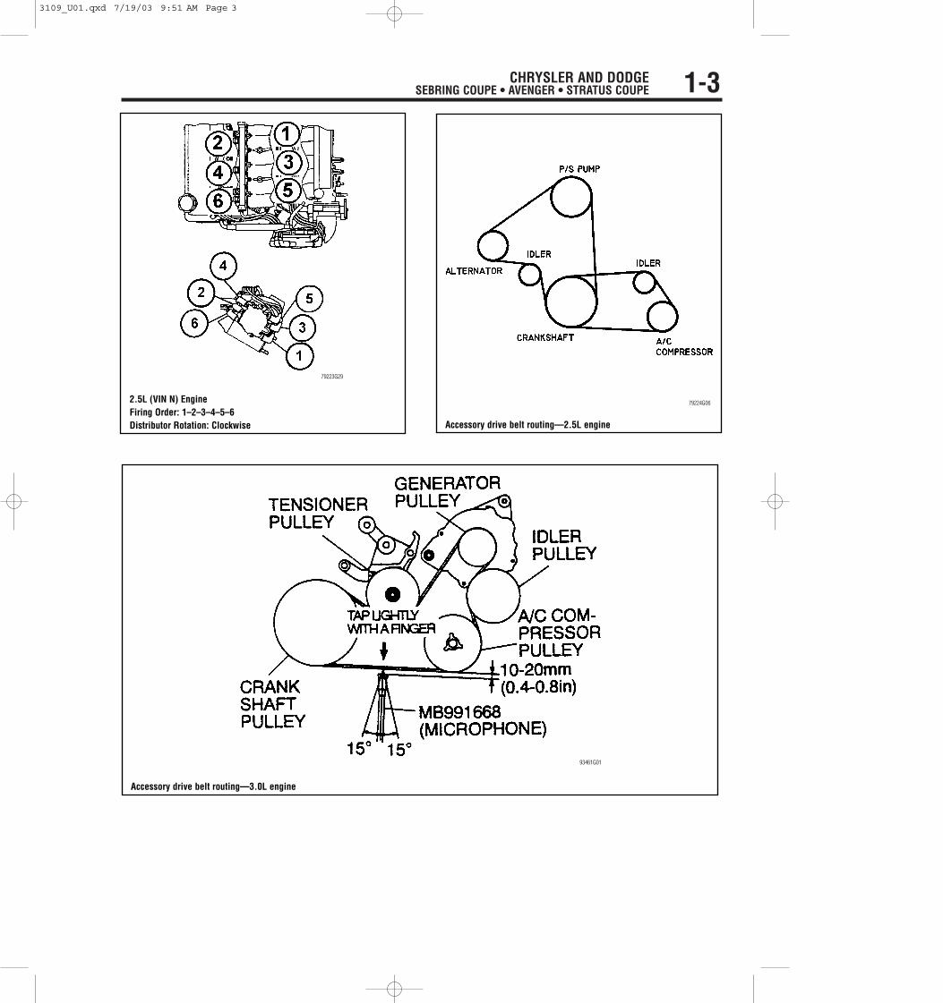
2.5L (VIN N) EngineFiring Order: 1–2–3–4–5–6Distributor Rotation: Clockwise
79223G29
Accessory drive belt routing—2.5L engine
79224G06
Accessory drive belt routing—3.0L engine
93461G01
3109_U01.qxd 7/19/03 9:51 AM Page 3
1-4 CHRYSLER AND DODGESEBRING COUPE • AVENGER • STRATUS COUPE
23991C04
23991C05
3109_U01.qxd 7/19/03 9:51 AM Page 4

CHRYSLER AND DODGESEBRING COUPE • AVENGER • STRATUS COUPE 1-5
23991C06
23991C07
3109_U01.qxd 7/19/03 9:51 AM Page 5

1-6 CHRYSLER AND DODGESEBRING COUPE • AVENGER • STRATUS COUPE
23991C08
23991C09
3109_U01.qxd 7/19/03 9:51 AM Page 6

CHRYSLER AND DODGESEBRING COUPE • AVENGER • STRATUS COUPE 1-7
23991C10
3109_U01.qxd 7/19/03 9:51 AM Page 7

1-8 CHRYSLER AND DODGESEBRING COUPE • AVENGER • STRATUS COUPE
23991C11
3109_U01.qxd 7/19/03 9:51 AM Page 8

CHRYSLER AND DODGESEBRING COUPE • AVENGER • STRATUS COUPE 1-9
23991C12
3109_U01.qxd 7/19/03 9:51 AM Page 9

1-10 CHRYSLER AND DODGESEBRING COUPE • AVENGER • STRATUS COUPE
PRECAUTIONS
Before servicing any vehicle, please besure to read all of the following precautions,which deal with personal safety, preventionof component damage, and important pointsto take into consideration when servicing amotor vehicle:
• Never open, service or drain the radia-tor or cooling system when the engine ishot; serious burns can occur from the steamand hot coolant.
• Observe all applicable safety precau-tions when working around fuel. Wheneverservicing the fuel system, always work in awell-ventilated area. Do not allow fuel sprayor vapors to come in contact with a spark,open flame or excessive heat (a hot droplight, for example). Keep a dry chemical fireextinguisher near the work area. Always keepfuel in a container specifically designed forfuel storage; also, always properly seal fuelcontainers to avoid the possibility of fire orexplosion. Refer to the additional fuel systemprecautions later in this section.
• Fuel injection systems often remainpressurized, even after the engine has beenturned OFF. The fuel system pressure mustbe relieved before disconnecting any fuellines. Failure to do so may result in fireand/or personal injury.
• Brake fluid often contains polyglycolethers and polyglycols. Avoid contact withthe eyes and wash your hands thoroughlyafter handling brake fluid. If you do getbrake fluid in your eyes, flush your eyeswith clean, running water for 15 minutes. Ifeye irritation persists, or if you have taken
brake fluid internally, IMMEDIATELY seekmedical assistance.
• The EPA warns that prolonged con-tact with used engine oil may cause anumber of skin disorders, including can-cer! You should make every effort to mini-mize your exposure to used engine oil.Protective gloves should be worn whenchanging oil. Wash your hands and anyother exposed skin areas as soon as pos-sible after exposure to used engine oil.Soap and water, or waterless hand cleanershould be used.
• All new vehicles are now equippedwith an air bag system, often referred to as aSupplemental Restraint System (SRS) orSupplemental Inflatable Restraint (SIR) sys-tem. The system must be disabled beforeperforming service on or around systemcomponents, steering column, instrumentpanel components, wiring and sensors.Failure to follow safety and disabling proce-dures could result in accidental air bagdeployment, possible personal injury andunnecessary system repairs.
• Always wear safety goggles whenworking with, or around, the air bag system.When carrying a non-deployed air bag, besure the bag and trim cover are pointedaway from your body. When placing a non-deployed air bag on a work surface, alwaysface the bag and trim cover upward, awayfrom the surface. This will reduce themotion of the module if it is accidentallydeployed. Refer to the additional air bagsystem precautions later in this section.
• Clean, high quality brake fluid from asealed container is essential to the safe andproper operation of the brake system. Youshould always buy the correct type of brakefluid for your vehicle. If the brake fluidbecomes contaminated, completely flush thesystem with new fluid. Never reuse anybrake fluid. Any brake fluid that is removedfrom the system should be discarded. Also,do not allow any brake fluid to come in con-tact with a painted surface; it will damagethe paint.
• Never operate the engine without theproper amount and type of engine oil;doing so WILL result in severe enginedamage.
• Timing belt maintenance is extremelyimportant! Many models utilize an interfer-ence-type, non-freewheeling engine. If thetiming belt breaks, the valves in the cylinderhead may strike the pistons, causing poten-tially serious (also time-consuming andexpensive) engine damage..
• Disconnecting the negative batterycable on some vehicles may interfere withthe functions of the on-board computer sys-tem(s) and may require the computer toundergo a relearning process once the neg-ative battery cable is reconnected.
• When servicing drum brakes, only dis-assemble and assemble one side at a time,leaving the remaining side intact for refer-ence.
• Only an MVAC-trained, EPA-certifiedautomotive technician should service the airconditioning system or its components.
ENGINE REPAIR
Distributor
REMOVAL
2.5L Engine
The 2.5L engine is equipped with acamshaft driven mechanical distributor.This engine uses a fixed ignition timingsystem, in which the basic ignition timingis not adjustable. The Powertrain ControlModule (PCM) determines spark advance.The Crankshaft Position (CKP) sensor andCamshaft Position (CMP) sensor are Halleffect devices. The CKP sensor is mountedremotely from the distributor, while theCMP sensor is mounted inside the distrib-utor housing. Both sensors generate pulsesthat serve as inputs to the PCM; the PCM
determines crankshaft position from thesesensors, then calculates injector sequenceand ignition timing, based on the data.
1. Before servicing the vehicle, refer tothe precautions in the beginning of this sec-tion.
2. Disconnect the negative batterycable.
3. Remove or disconnect, if necessaryfor access:
• Air inlet resonator to the intakemanifold bolt
• Air cleaner cover to air cleanerhousing cover clamps
• Positive Crankcase Ventilation(PCV) make-up air hose from theair inlet tube
• Throttle body hose clamp• Air cleaner cover, resonator and
inlet tube
• Exhaust Gas Recirculation (EGR)tube
4. Remove or disconnect the follow-ing:
• Spark plug wires from the distribu-tor cap
• Distributor cap5. Matchmark the rotor-to-distributor
and the distributor-to-engine positioning tohelp with installation.
• Rotor• Distributor’s 2 electrical harness
connectors• Distributor hold-down nuts and
washers• Spark plug cable mounting bracket,
if necessary• Transaxle dipstick tube• Distributor
3109_U01.qxd 7/19/03 9:51 AM Page 10

INSTALLATION
2.5L Engine
TIMING NOT DISTURBED➦Before servicing the vehicle, refer tothe precautions in the beginning of thissection.
1. Inspect the rotor for cracks or burnedelectrodes, and replace if defective. Installthe rotor onto the distributor.
2. Inspect the O-ring seal. If nicked orcracked, replace with a new one. Be sure theO-ring is properly seated on the distributor.
3. Install or connect the following:• Distributor drive with the slotted
end of the camshaft
➦When the distributor is installedproperly, the rotor will be aligned withthe previously made mark.
• Distributor hold-down nuts/wash-ers and tighten to 108 inch lbs. (13Nm)
• Spark plug cable bracket• Both distributor wiring connec-
tors• Distributor cap• Spark plug cables• Transaxle dipstick tube• EGR tube and tighten the bolts to
95 inch lbs. (11 Nm)• Air cleaner cover, resonator and
inlet tube• Throttle body hose clamp• PCV hose• Air cleaner housing cover clamps• Air inlet resonator to intake mani-
fold bolt• Negative battery cable
TIMING DISTURBED1. Rotate the crankshaft until the No. 1
piston is at Top Dead Center (TDC) of thecompression stroke.
2. Align the rotor with the distributorhousing matchmark.
3. Install or connect the following:• Distributor
➦With the distributor fully seated, therotor should align the No. 1 terminal ofthe distributor cap.
• Distributor hold-down nuts/wash-ers and tighten the nuts to 108 inchlbs. (13 Nm)
• Spark plug cable bracket• Both distributor wiring connectors• Distributor cap• Spark plug cables• Transaxle dipstick tube
4. Install or connect the following, ifremoved:
• EGR tube and tighten the bolts to95 inch lbs. (11 Nm)
• Air cleaner cover, resonator andinlet tube
• Throttle body hose clamp• PCV hose• Air cleaner housing cover clamps• Air inlet resonator to intake mani-
fold bolt• Negative battery cable
Alternator
REMOVAL
2.4L Engine
1. Before servicing the vehicle, refer to theprecautions in the beginning of this section.
2. Remove or disconnect the following:
• Negative battery cable• Engine under cover• Engine mount bracket• Oil pressure hose and tube clamp
bolts• Oil return tube clamp bolt• Power steering and A/C drive
belt• Alternator drive belt• Water pump pulley• Alternator connector• Alternator brace• Alternator bolt and nut• Alternator
2.5L Engine
1. Remove or disconnect the follow-ing:
• Negative battery cable• Right front wheel• Wheel well side cover• Auto-cruise control reservoir
assembly• Power steering pump drive belt
cover• A/C compressor drive belt• Power steering pump/alternator
drive belt• Intake manifold plenum• Alternator bracket• Intake manifold plenum stay• Alternator electrical connectors• Alternator
3.0L Engine
1. Before servicing the vehicle, refer tothe precautions in the beginning of this sec-tion.
CHRYSLER AND DODGESEBRING COUPE • AVENGER • STRATUS COUPE 1-11
Prior to installation, align the distributorshaft with the distributor housing—2.5Lengine
7922CG01
Exploded view of the alternator and related components—2.4L engine
9356CG01
3109_U01.qxd 7/19/03 9:51 AM Page 11

2. Remove or disconnect the following:• Negative battery cable• Engine under cover• Engine mount bracket• Drive belt• Alternator belt• Oil level gauge unit• Alternator electrical connectors• Alternator brace• Alternator
INSTALLATION
2.4L Engine
1. Install or connect the following:• Alternator• Alternator bolt and nut. Tighten to
26–40 ft. lbs. (34–54 Nm).• Alternator brace• Alternator connector
• Water pump pulley• Alternator drive belt• Power steering and A/C drive belt• Oil return tube clamp bolt• Oil pressure hose and tube clamp
bolts• Engine mount bracket
2. Adjust the belt tension.• Negative battery cable• Under cover
2.5L Engine
1. Install or connect the following:• Alternator• Alternator electrical connectors• Intake manifold plenum stay• Alternator bracket. Torque the alter-
nator-to-lower alternator bracketnut to 30 ft. lbs. (41 Nm) and thealternator-to-upper bracket bolt to16 ft. lbs. (22 Nm).
• Intake manifold plenum• Power steering pump/alternator
drive belt2. Attach a belt tension gauge midway
on the drive belt, between the alternator andpower steering pump pulleys; then, adjustthe drive belt tension to 99–121 lbs.(440–540 N) for a used belt or 143–187lbs. (642–838 N) for a new belt.
3. Torque the tension pulley bracket nutto 17 ft. lbs. (24 Nm).
4. Install the A/C compressor’s drivebelt.
5. Attach a belt tension gauge midwayon the drive belt, between the crankshaftand tension pulleys; then, adjust the drivebelt tension to 66–86 lbs. (295–385 N) fora used belt or 110–132 lbs. (490–590 N)for a new belt.
1-12 CHRYSLER AND DODGESEBRING COUPE • AVENGER • STRATUS COUPE
Exploded view of the alternator and related components—2.5L engine
9306CG01
View of the auto-cruise speed control and related components—2.5L engines
9306CG03
3109_U01.qxd 7/19/03 9:51 AM Page 12