chromatic aberration -...
TRANSCRIPT

Chromatic Aberration
CEDEC 2001Tokyo, Japan
Chromatic Aberration
CEDEC 2001Tokyo, Japan

2
Mark J. KilgardGraphics Software EngineerNVIDIA Corporation
3
Chromatic Aberration
• Refraction through surfaces can be wave-length dependent
• Examples:• Crystal sculptures• Soap bubbles• Poor quality lens• Prism• Rainbows
• Physics of chromatic aberration• Physically plausible rendering model is hard• But cool hacks are possible today!
4
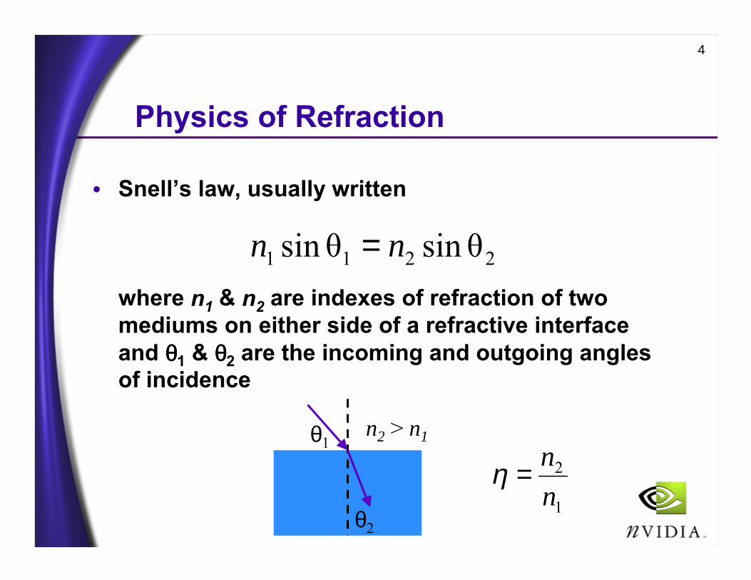
Physics of Refraction
• Snell’s law, usually written
where n1 & n2 are indexes of refraction of two mediums on either side of a refractive interfaceand θθθθ1 & θθθθ2 are the incoming and outgoing angles of incidence
2211 θsinθsin nn =
θ1
θ2
n2 > n1
1
2
nn=η

5
Wavelength DependentRefraction
• The index of refraction for most translucent materials is wavelength dependent• n is a function of wavelength λλλλ
• Chromatic aberration (optics term) is the visual effect of wavelength dependent refraction
θ1
θ2red
n2red > n2green > n2blue > n1
θ2greenθ2blue
6
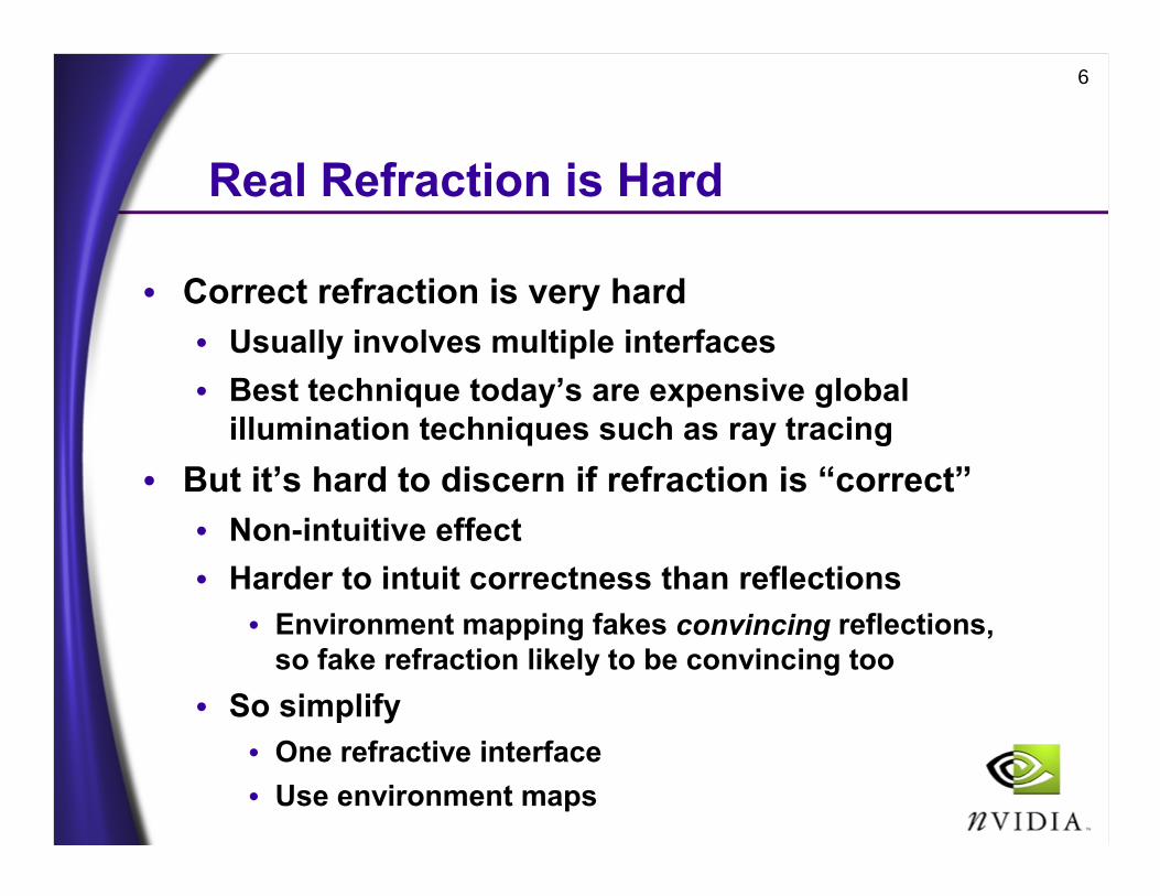
Real Refraction is Hard
• Correct refraction is very hard• Usually involves multiple interfaces• Best technique today’s are expensive global
illumination techniques such as ray tracing• But it’s hard to discern if refraction is “correct”
• Non-intuitive effect• Harder to intuit correctness than reflections
• Environment mapping fakes convincing reflections, so fake refraction likely to be convincing too
• So simplify• One refractive interface• Use environment maps

7
Sketch of a ChromaticAberration Technique (1)
• Per-vertex, compute• Three refraction vectors given surface normal,
view direction, & indices of refraction• one refraction vector for red, green, and blue
• different indices of refraction for each• compute refraction vectors using vertex programs
• Sample single RGB cube map texture object• Extract respective color component for each
refraction vector• Combine the components in the register
combiners

8
Sketch of a ChromaticAberration Technique (2)
• Also blend in conventional reflective environment mapping contribution• Again, access same RGB environment map• Most transparent surfaces refract and reflect
• Scalable technique for different GPUs• Single-texture GPU, 4 passes• Dual-texture GPU (TNT, GeForce 1/2), 2 passes• Quad-texture GPU (GeForce3), 1 pass• Use CPU math when vertex programs not available
• Credit for idea & demo: Simon Green, NVIDIA

9
2D View of ChromaticAberration Rendering Technique
View vector
Reflected viewvector
Surface normalvector Surface
(refraction interface)
Cube mapenvironment
map
Red, green, & bluerefracted view vectors

10
Example Refraction/ReflectionEnvironment Map Cube Map
Credit: Paul Debevec
11
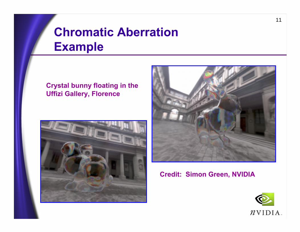
Chromatic AberrationExample
Crystal bunny floating in the Uffizi Gallery, Florence
Credit: Simon Green, NVIDIA

12
Per-vertex RefractionVector Computations
• Two refraction vector techniques• Physically-based vector approach
• RenderMan approach
• Where I=incident vector (to eye), N=normal, and η=ratio of two indices of refraction; to computethe refraction vector R
( ) ININIINR ˆˆˆˆ1ˆˆˆ 22 ηηη −
•−−−•=
( )
( )NkNIIkk
R
NIk
ˆˆˆˆ,0)0,0,0(,0
ˆˆ1122
+•−≥<
=
•−−=
ηη
η
13
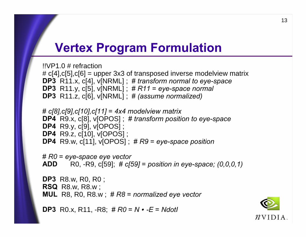
Vertex Program Formulation!!VP1.0 # refraction# c[4],c[5],c[6] = upper 3x3 of transposed inverse modelview matrixDP3 R11.x, c[4], v[NRML] ; # transform normal to eye-spaceDP3 R11.y, c[5], v[NRML] ; # R11 = eye-space normalDP3 R11.z, c[6], v[NRML] ; # (assume normalized)
# c[8],c[9],c[10],c[11] = 4x4 modelview matrixDP4 R9.x, c[8], v[OPOS] ; # transform position to eye-spaceDP4 R9.y, c[9], v[OPOS] ;DP4 R9.z, c[10], v[OPOS] ;DP4 R9.w, c[11], v[OPOS] ; # R9 = eye-space position
# R0 = eye-space eye vectorADD R0, -R9, c[59]; # c[59] = position in eye-space; (0,0,0,1)
DP3 R8.w, R0, R0 ;RSQ R8.w, R8.w ;MUL R8, R0, R8.w ; # R8 = normalized eye vector
DP3 R0.x, R11, -R8; # R0 = N • -E = NdotI

14
First Refraction Based on η1
# c[58] = (η1, η1*η1, 0.0, 1.0 )
# R1.x = 1-(NdotI)^2MAD R1.x, -R0.x, R0.x, c[58].w ;# R1.x = k = 1.0- η1*η1*R1.xMAD R1.x, R1.x, c[58].y, -c[58].w ;
RSQ R2.x, R1.x ; RCP R2.x, R2.x ; # R2.x = sqrt(k)MAD R2.x, c[58].x, R0.x, R2.x ; MUL R2, R11, R2.x ; MAD R2, c[58].x, -R8, R2 ; # R = η1*I-(η1*NdotI+sqrt(k))*N
DP3 o[TEX0].x, c[12], R2 ; # rotate refraction rayDP3 o[TEX0].y, c[13], R2 ; # by cube map transformDP3 o[TEX0].z, c[14], R2 ;
15
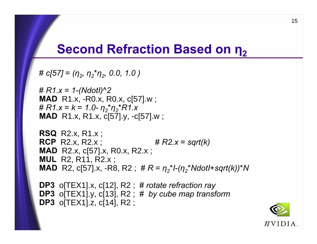
Second Refraction Based on η2
# c[57] = (η2, η2*η2, 0.0, 1.0 )
# R1.x = 1-(NdotI)^2MAD R1.x, -R0.x, R0.x, c[57].w ;# R1.x = k = 1.0- η2*η2*R1.xMAD R1.x, R1.x, c[57].y, -c[57].w ;
RSQ R2.x, R1.x ; RCP R2.x, R2.x ; # R2.x = sqrt(k)MAD R2.x, c[57].x, R0.x, R2.x ; MUL R2, R11, R2.x ; MAD R2, c[57].x, -R8, R2 ; # R = η2*I-(η2*NdotI+sqrt(k))*N
DP3 o[TEX1].x, c[12], R2 ; # rotate refraction rayDP3 o[TEX1].y, c[13], R2 ; # by cube map transformDP3 o[TEX1].z, c[14], R2 ;
16
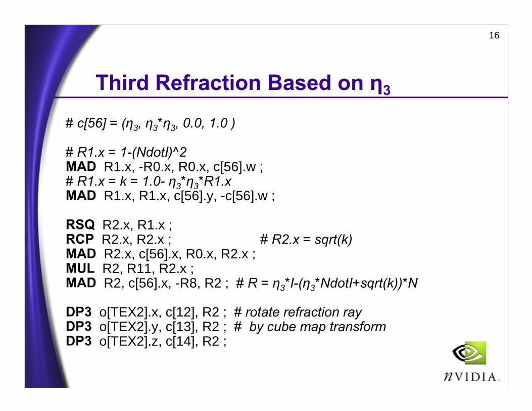
Third Refraction Based on η3
# c[56] = (η3, η3*η3, 0.0, 1.0 )
# R1.x = 1-(NdotI)^2MAD R1.x, -R0.x, R0.x, c[56].w ;# R1.x = k = 1.0- η3*η3*R1.xMAD R1.x, R1.x, c[56].y, -c[56].w ;
RSQ R2.x, R1.x ; RCP R2.x, R2.x ; # R2.x = sqrt(k)MAD R2.x, c[56].x, R0.x, R2.x ; MUL R2, R11, R2.x ; MAD R2, c[56].x, -R8, R2 ; # R = η3*I-(η3*NdotI+sqrt(k))*N
DP3 o[TEX2].x, c[12], R2 ; # rotate refraction rayDP3 o[TEX2].y, c[13], R2 ; # by cube map transformDP3 o[TEX2].z, c[14], R2 ;
17
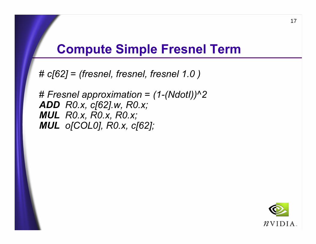
Compute Simple Fresnel Term
# c[62] = (fresnel, fresnel, fresnel 1.0 )
# Fresnel approximation = (1-(NdotI))^2ADD R0.x, c[62].w, R0.x; MUL R0.x, R0.x, R0.x; MUL o[COL0], R0.x, c[62];

18
Compute Reflection
# c[64].z = 2.0MUL R0, R11, c[64].z; # R0 = 2*NDP3 R3.w, R11, R8; # R3.w = N dot EMAD R3, R3.w, R0, -R8; # R3 = 2*N * (N dot E) - E
# transform reflected ray by cube map transformDP3 o[TEX3].x, c[12], R3; DP3 o[TEX3].y, c[13], R3; DP3 o[TEX3].z, c[14], R3;
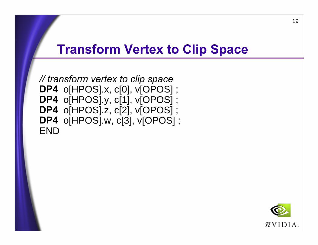
19
Transform Vertex to Clip Space
// transform vertex to clip spaceDP4 o[HPOS].x, c[0], v[OPOS] ;DP4 o[HPOS].y, c[1], v[OPOS] ;DP4 o[HPOS].z, c[2], v[OPOS] ;DP4 o[HPOS].w, c[3], v[OPOS] ;END

20
Per-fragment Math to CombineReflection and Refractions
• Combine refractionsRefractedColor = red(cubemap(tex0)) +
green(cubemap(tex1)) +blue(cubemap(tex2))
• Compute reflected colorReflectedColor = cubemap(tex3)
• Combine color based on Fresnel termcolor = primaryColor * ReflectedColor +
(1-primaryColor) * RefractedColor

21
Improvements, Optimizations, &Suggestions
• Dynamic environment mapping• Render environment map per-frame
• Vertex program optimizations• Combine scalar instructions together• Perform vector math in cube map space rather
than in eye space to save DP3s• Very cheap refraction approximation
Bends ray towards normal in proportion to η
NER ˆˆ η−=
22
Conclusions
• Chromatic aberration• Environment mapping-style technique• Convincing if not physically plausible• Requires cube maps• Accelerated by
• Vertex programs• Multiple hardware texture units
• Inventor• Simon Green, NVIDIA