christie warner electrical contractor
TRANSCRIPT

CHRISTIE WARNERElectrical Contractor

Knockout, drive, drill, cut & punch. You’ll get through it with Greenlee.
Quick Draw® FlexDriver
724 Steel StudPunch
• New 3-4 tooth-design holesaws are 20% faster than ordinary holesaws
• High speed cutters offer lowest cost per hole and last ten times longer than ordinary holesaws for clean,burr-free edges
• Quick Draw® Flex Driver features a fully flexible neck to position the knockout punch in the desired location
• The patented Greenlee 724 Steel Stud Punch is designed tomanually punch a square hole in steel studs. Better yet, thepatented design rolls the edges over, decreasing the potentialof hang-ups in the installation of armored cable and PVC conduit for applications where code does not require a bushing
4
HO
LE
MA
KIN
G

USA Tel: 800-435-0786 Canada Tel: 800-435-0786 International Tel: +1-815-397-7070Fax: 800-451-2632 Fax: 800-524-2853 Fax: +1-815-397-9247
HO
LE
MA
KIN
G
Holemaking Selection Guide
greenlee.com
5
MATERIAL NUMBERMATERIAL TYPE THICKNESS OF HOLES PRODUCTS APPLICATION CONSIDERATIONS PAGES
Steel 10GA Highest Slugsplitter Punches Maximum durability and universal 8-9material usage
Maximum hole size 2-1/2 inches10GA High Slugbuster Punches Maximum hole size 2-1/2 inches 10-2310GA High Standard Punches Maximum hole size 5-5/8 inches 11, 24-2910GA High High Speed Cutters Maximum hole size 2-1/2 inches 448GA Medium Carbide-Tipped Hole Cutters Maximum hole size 2-1/2 inches 4310GA Medium Step Bits Maximum hole size 1-3/8 inches 4110GA Low Hole Saws Maximum hole size 6 inches 45-48
Stainless Steel 10GA Highest Slugsplitter Punches Maximum durability and universal material usage 8-9Maximum hole size 2-1/2 inches
10GA Medium Slugbuster Punches Maximum hole size 2-1/2 inches 10-239GA Medium Kwik Change Cutters Maximum hole size 3 inches, quick change 42
cutting heads8GA Medium Carbide-Tipped Hole Cutters Maximum hole size 2-1/2 inches 4310GA Low Hole Saws Run at 200 RPM, high pressure (150 lbs.) 45-48
Wood 18 inches High Naileater Power Bits Cuts through nails, good chip removal, max hole size 521-1/4 inches
2–2 x 4’s High E-Z Bore Bits Self feed screw for hard or soft woods, max hole size 53-544-5/8 inches
2 x 4 High Step Bits Maximum hole size 1-3/8 inches, low chip removal 4116 inches Medium Spade Bits Maximum hole size 1-1/2 inches 581-5/8" or 2 x 4 Medium Hole Saws Best on thinner wood, low chip removal, max hole size 45-48
6 inchesAluminum 10GA Highest Slugsplitter Punches Maximum durability and universal material usage 8-9
Maximum hole size 2-1/2 inches10GA High Slugbuster Punches Maximum hole size 2-1/2 inches 10-2310GA High Standard Punches Maximum hole size 5-5/8 inches 11, 24-2910GA High High-Speed Cutters Maximum hole size 2-1/2 inches 4410GA Medium Step Bits Maximum hole size 1-3/8 inches 4110GA Low Hole Saws Maximum hole size 6 inches 45-48
Fiberglass/Plastic approx. 1/8" Highest Slugsplitter Punches Maximum durability and universal material usage 8-9Maximum hole size 2-1/2 inches
approx. 1/8" High Slugbuster Punches Maximum hole size 2-1/2 inches 10-23approx. 1/8" High Standard Punches Maximum hole size 5-5/8 inches 11, 24-29approx. 1/8" High High-Speed Cutters Maximum hole size 2-1/2 inches 44approx. 1/8" Medium Step Bits Maximum hole size 1-3/8 inches 411-5/8" Low Hole Saws Maximum hole size 6 inches 45-48
Drywall/Ceiling Tile 7/8" High Recessed light hole saws Replaceable blades 597/8" Medium Quick Cutter Adjustable or fixed, sprinkler heads or lighting 597/8" Medium Keyhole Saw Non-round holes 59
Quazite®* Enclosures High Slugbuster Punches 10-23approx. 1/8" Medium Carbide-Grit Hole Saws 46
Hardyboard siding Medium Carbide-Grit Hole Saws 46Cement board Medium Carbide-Grit Hole Saws 46Existing Wall D’versibits Remodeling, phone, cable, alarm installation 55-57Non-round hole High Non-round Punches Square, rectangular, electronic connector holes 33-35
Medium Reciprocating Blades 49Medium Jigsaw Blades 50
Non-conduit sizes 16-10GA High Standard Punches 11Metal Studs 20GA Stud Punches 39-40
*Quazite is a registered trademark of Strongwell Corporation

6
USA Tel: 800-435-0786 Canada Tel: 800-435-0786 International Tel: +1-815-397-7070Fax: 800-451-2632 Fax: 800-524-2853 Fax: +1-815-397-9247
greenlee.comH
OL
EM
AK
ING
Knockout Punch and Driver Selection Guide
PUNCH TYPE DRIVE METHOD CAPACITY SIZE RANGE AVAILABLE PAGES
Slug-Splitter® Ratchet, Hydraulic or Battery Up thru 10 gauge (3.5 mm) .598" through 2.526" dia. 8stainless steel or mild steel (15.2 mm through 64 mm)
Slug-Buster® Manual, Ratchet, Hydraulic or Battery Up thru 10 gauge .492" through 2.52" dia. 10(3.5 mm) mild steel (12.5 mm through 64.0 mm)
Standard Round Manual, Ratchet, Hydraulic or Battery Up thru 10 gauge (3.5 mm) 1/2" through 5-5/8" dia. 11, 25mild steel and aluminum (12.7 through 143.7 mm)
DRIVER TYPE DESCRIPTION KITS PAGES
Battery-Powered • Develops 6.7 tons of hydraulic force. Available in kits with driver only or with 15or Corded • Available with three choice of battery chargers – driver and Slug-Buster® knockout Hydraulic Driver 115, 230 or 12 volt. punches.
• Punches up through 10 gauge (3.5 mm) mild steelwith Greenlee standard and Slug-Buster® knockoutpunches and 12 gauge (2.5 mm) stainless steel withGreenlee Slug-Splitter® knockout punches.
Hand Pump • Powerful hydraulic ram develops 11 tons of Available in kits with driver only 19hydraulic force. or with driver and either standard,
Hydraulic Driver • Punches up thru 10 gauge (3.5 mm) mild steel with Slug-Buster®or Slug-Splitter®
with Ram Greenlee standard and Slug-Buster® knockout knockout punches.punches and 10 gauge (3.5 mm) stainless steel withGreenlee Slug-Splitter® knockout punches.
Foot Pump • Foot operation frees both hands to operate punch. Available in kits with driver only or with 17Hydraulic Driver • Powerful hydraulic ram develops 11 tons of hydraulic driver and either standard, Slug-Buster®
with Ram force. or Slug-Splitter® knockout punches.• Punches up through 10 gauge (3.5 mm) mild steel
with Greenlee Standard and Slug-Buster® knockout punches; and 10 gauge (3.5 mm) stainless steel with Greenlee Slug-Splitter® knockout punches.
Quick Draw™ Flex • Allows unlimited driver orientation to simplify access 21Hydraulic Driver to work area
• Develops 8 tons of hydraulic force for easy punching.• Punches up through 10 gauge (3.5 mm) mild steel
with Greenlee Standard and Slug-Buster® knockout punches; and 10 gauge (3.5 mm) stainless steel with Greenlee Slug-Splitter® knockout punches.
Quick Draw 90™ • Right angle driver head rotates over 180 degrees for Available in kits with driver only or with 21Hydraulic Driver maximum flexibility in tight working areas. driver and Slug-Buster® knockout
• Develops 8 tons of hydraulic force for easy punching. punches.• Punches up through 10 gauge (3.5 mm) mild steel
with Greenlee Standard and Slug-Buster® knockout punches; and 10 gauge (3.5 mm) stainless steel with Greenlee Slug-Splitter® knockout punches.
Quick Draw™ • Perfect for fast, straight-on front panel punching. Available in kits with driver only or with 21Hydraulic Driver • Develops 8 tons of hydraulic force for easy punching. driver and Slug-Buster® knockout
• Punches up through 10 gauge (3.5 mm) mild steel punches.with Greenlee Standard and Slug-Buster® knockout punches; and 10 gauge (3.5 mm) stainless steel with Greenlee Slug-Splitter® knockout punches.
High Leverage • Time saving ball bearing head punches faster than Available in kits with driver only or with 23Ratchet Driver wrench method. driver and Slug-Buster® knockout
• Punches up through 10 gauge (3.5 mm) mild steel punches.with Greenlee Standard Slug-Buster® knockout punches; and16 gauge (1.5 mm) stainless steel with Greenlee Slug-Splitter® knockout punches.
KnockoutPunch
KnockoutPunch Driver

HO
LE
MA
KIN
G
STANDARD SLUGBUSTER SIZE DIFFERENCECAT. NO. UPC NO. DESCRIPTION CAT. NO. UPC NO. (SLUGBUSTER TO STANDARD)121AV 04006 1/2" STANDARD PUNCH 721-1/2 31756123AV 04008 3/4" STANDARD PUNCH 721-3/4 31757125AV 04010 1" STANDARD PUNCH 721-1 31758127AV 06974 1-1/4" STANDARD PUNCH 721-1-1/4 317591756AV 04232 PUNCH 2.00 (50.8) 35160 3516017687 17687 PUNCH 1.85 (47.0) 721E-47 3200917690 17690 PUNCH 2.36 (60.0) 721E-60 3201117697 17697 PUNCH 0.80 (20.4) 721E-20.4 3197117700 17700 PUNCH 0.73 (18.6) 721E-18.6 319701783AV 04245 PUNCH 2.12 (54.0) 36172 3617218331 18331 PUNCH 1.45 (37.0) 721E-37.0 3197521115 21115 PUNCH UNIT PG 9 (15.2) 7211EBB-15.2 3198921316 21316 PUNCH 0.59 (15.2) 721E-15.2 3196924459 24459 PUNCH 1.28 (32.5) 35169 3516924462 24462 PUNCH 1.59 (40.5) 35158 3515824476 24476 PUNCH UNIT 1.28 (32.5) 35179 3517924477 24477 PUNCH UNIT 1.59 (40.5) 35180 3518035192 35192 PUNCH UNIT 0.63 (16.2) 35177 3517736282 36282 1-7/32" STANDARD PUNCH 60237 6023736505 36505 PUNCH UNIT 1.21 (30.5) 60246 6024636506 36506 1-7/32" STANDARD PUNCH UNIT 60246 6024636686 36686 PUNCH SET PG 9 (30.5) 36690 3669036687 36687 PUNCH SET PG9 (48) 36691 3669136688 36688 PUNCH SET ISO 16-40 36692 3669236689 36689 PUNCH SET ISO 16-64 36693 3669336882 36882 PUNCH 1.11 (28.3) 721E-28.3 3197336910 36910 PUNCH UNIT 1.11 (28.3) 7211EBB-28.3 31993439AV 06978 1-1/2" STANDARD PUNCH 721-1-1/2 31760441AV 04062 2" STANDARD PUNCH 721-2 3176171BB 22563 1/2" STANDARD PUNCH UNIT 7211BB-1/2 3196272BB 22564 3/4" STANDARD PUNCH UNIT 7211BB-3/4 3196373BB 22565 1" STANDARD PUNCH UNIT 7211BB-1 31964730-1/2 02408 PUNCH UNIT 0.50 (12.7) 06727 06727 12.5 mm vs.12.7 mm730-5/8 02409 PUNCH UNIT 0.62 (15.9) 35177 35177 16.2 mm vs.15.9 mm730-9/16 02433 PUNCH UNIT 0.56 (14.3) 7211EBB-15.2 31989 15.2 mm vs.14.3 mm730BB-1 20670 PUNCH UNIT 1.00 (25.4) 35178 35178730BB-11/16 25340 PUNCH UNIT 0.68 (17.5) 7211EBB-18.6 31990 18.6 mm vs.17.5 mm730BB-1-1/4 20673 PUNCH UNIT 1.25 (31.8) 35179 35179 32.5 mm vs.31.8 mm730BB-1-1/8 20671 PUNCH UNIT 1.12 (28.6) 7211EBB-28.3 31993 28.3 mm vs.28.6 mm730BB-13/16 20668 PUNCH UNIT 0.81 (20.6) 7211EBB-20.4 31991 20.4 mm vs.20.6 mm730BB-1-3/8 25427 PUNCH UNIT 1.37 (34.9) 7211BB-1 31964 34.6 mm vs.34.9 mm730BB-2 20676 PUNCH UNIT 2.00 (50.8) 35181 35181730BB-2-1/2 20679 PUNCH UNIT 2.50 (63.5) 35182 35182 64 mm vs.63.5 mm730BB-2-1/8 20678 PUNCH UNIT 2.12 (54.0) 36171 36171730EBB-18.6 18886 PUNCH UNIT 0.73 (18.6) 7211EBB-18.6 31990730EBB-20.4 18887 PUNCH UNIT 0.80 (20.4) 7211EBB-20.4 31991730EBB-37.0 18890 PUNCH UNIT 1.45 (37.0) 7211EBB-37 31995730EBB-47.0 18891 PUNCH UNIT 1.85 (47.0) 7211EBB-47 31996730EBB-60.0 18892 PUNCH UNIT 2.36 (60.0) 7211EBB-60 319987306 15909 HYDRAULIC PUNCH SET 7306SB 343607309E 32804 PUNCH SET 36691 366917310 15910 HYDRAULIC PUNCH SET 7310SB 34361735BB 19973 1/2" to 1-1/4" STANDARD KNOCKOUT KIT 7235BB 32013737BB 19974 1-1/2" - 2" STANDARD KNOCKOUT KIT 7237BB 3201474BB 22566 1-1/4" STANDARD PUNCH UNIT 7211BB-1-1/4 3196575BB 22567 1-1/2" STANDARD PUNCH UNIT 7211BB-1-1/2 3196676BB 22568 2" STANDARD PUNCH UNIT 7211BB-2 3196787AV 03986 PUNCH 1.00 (25.4) 35165 35165
Standard Round Punch to Slugbuster Punch Cross Reference
7
USA Tel: 800-435-0786 Canada Tel: 800-435-0786 International Tel: +1-815-397-7070Fax: 800-451-2632 Fax: 800-524-2853 Fax: +1-815-397-9247
greenlee.com

8
USA Tel: 800-435-0786 Canada Tel: 800-435-0786 International Tel: +1-815-397-7070Fax: 800-451-2632 Fax: 800-524-2853 Fax: +1-815-397-9247
greenlee.comH
OL
EM
AK
ING
Unique Slug-Splitter®
punch design creasesslug as the punch isdrawn into the die.
Slug is split in half aspunching operation is completed.
Split slugs fall freefrom the die and stud.
SPECIFICATIONS
Capacity Stainless steel up through 10 gauge (3.5 mm).
Application 10 gauge stainless steel, mild steel, fiberglass and plastic enclosures.
Hole SizesConduit Sizes – Hole size is outside diameter of US conduit sizes.
Example: 1/2" conduit size punch actually makes a 7/8" hole.Pg Sizes – European standard pipe sizesISO Sizes – International Standards Organization pipe sizes.
Operation Operate with battery, hydraulic or high leverage ratchet driver only.
PUNCH DIE DRAW STUDS
HOLE SIZE CAPACITY DRAW STUDSPUNCH DIE CONDUIT ACTUAL STAINLESS STEEL HYDRAULIC DRIVERS RATCHET DRIVER*CAT./UPC NO. CAT./UPC NO. & PIPE Ø (INCH) Ø (mm) PG ISO GA. (mm) 7804/7904 7646/7625 190431117 31126 — — .598 15.2 9 — 12 2.5 29451 29451 3022731119 31128 — — .732 18.6 11 — 12 2.5 29451 29451 3022731120 31129 — — .803 20.4 13 20 12 2.5 29451 29451 3022728154 28155 1/2" 7/8 .885 22.5 16 — 10 3.5 29451 29451 3022728156 28157 3/4" — 1.115 28.3 21 — 10 3.5 31872 29452 1209836490 36489 — 1-7/32 1.210 30.5 — — 10 3.5 31872 29452 1209828158 28159 1" 1-11/32 1.362 34.6 — — 10 3.5 31872 29452 1209831122 31135 — — 1.457 37.0 29 — 10 3.5 31872 29452 1209828160 28161 1-1/4" 1-11/16 1.701 43.2 — — 10 3.5 31872 29452 1209831123 31131 — — 1.850 47.0 36 — 10 3.5 — 29452 1209828162 28163 1-1/2" 1-15/16 1.951 49.6 — — 10 3.5 — 29452 1209831124 31132 — — 2.125 54.0 42 — 10 3.5 — 29452 1209831125 31133 — — 2.362 60.0 48 — 10 3.5 — 29452 1209828165 28166 2" 2-3/8 2.416 61.5 — — 10 3.5 — 29452 1209804599 04598 — — 0.638 16.2 — 16 12 2.5 29451 29451 3022704602 04601 — 1 1.000 25.4 — 25 10 3.5 31872 29452 1209804605 04603 — — 1.280 32.5 — 32 10 3.5 31872 29452 1209804608 04607 — — 1.595 40.5 — 40 10 3.5 31872 29452 1209804611 04609 — 2 2.000 50.8 — 50 10 3.5 — 29452 1209804614 04613 — — 2.520 64.0 — 63 10 3.5 — 29452 12098
* 16 ga. stainless steel capacity with ratchet driver.
PUNCH UNIT
PUNCH UNIT – INCLUDES HOLE SIZE CAPACITY DRIVERPUNCH, DIE & DRAW CONDUIT & ACTUAL STAINLESS STEEL WEIGHT LS60*/
CAT. NO. UPC NO. PIPE SIZE Ø INCH Ø mm GA mm LBS. kg 1904 7804/7904 CLC60 7646/7625 DRAW STUD
745R-1/2 30384 1/2" 7/8 .885 22.5 16 1.5 .6 .27 x 30227
745H-1/2 29560 1/2" 7/8 .885 22.5 10 3.5 .7 .32 x x x 29451
740H-1-7/32 29563 — 1-7/32 1.210 30.5 10 3.5 1.2 .54 x x x 29452Oil Tight
* Battery-Powered or Corded Knockout Punch Driver
Slug-Splitter® Knockout Punches 0.598" to 2.520"
Designed for stainless steel applications • Slug-Splitter® heavy-duty punches are designed to punch up through 10 gauge (3.5 mm) stainless steel.
• Unique slug splitting design and tool steel construction easily punch 10 gauge (3.5 mm) mild steel and stainless steel.
• Heavy-duty dies and stainless steel draw studs for longer life.• Excellent abrasion resistance for punching fiberglass and plastic.• Slug-Splitter® Punch Units consist of: punch, die and draw stud.
Check individual punch for specific capacity.• U.S. Patent No. 4,543,722.

9
USA Tel: 800-435-0786 Canada Tel: 800-435-0786 International Tel: +1-815-397-7070Fax: 800-451-2632 Fax: 800-524-2853 Fax: +1-815-397-9247
HO
LE
MA
KIN
Ggreenlee.com
WEIGHTCAT. NO. UPC NO. DESCRIPTION LBS. kg.744 29619 1/2" through 1-1/4" Conduit Size Slug-Splitter®
Knockout Punch Kit 5 2.37307 29528 1/2" through 2" Conduit Size Slug-Splitter®
Knockout Punch Kit 10.4 4.77506 30385 1/2" through 2" Conduit Size Slug-Splitter®
Knockout Punch Kit with Hydraulic Ramand Hand Pump 32 14.5
SPECIFICATIONS
Operation744/29619 – Quick Draw®, Quick Draw 90® and Quick Draw® Flex hydraulicdrivers, Battery-Powered drivers, 7646 and 7625 ram-type drivers.7307/29528 – Quick Draw®, Quick Draw 90® and Quick Draw® Flex hydraulicdrivers, Battery-Powered drivers, 7646 and 7625 ram-type drivers.7506/30385 – Hydraulic ram and hand pump included.
NOTE: See Slug-Splitter® Knockout Punch Units on page 8 for list of individual punches, dies and draw studs.
HOLE SIZE CAPACITY KIT CAT./UPC NO.CONDUIT & ACTUAL STAINLESS STEEL 744/ 7307/ 7506/
CAT. NO. UPC NO. DESCRIPTION PIPE SIZE Ø INCH Ø mm GA mm 29619 29528 3038528154 28154 1/2" Conduit Size Punch 1/2" 7/8 .885 22.5 10 3.5 ✓ ✓ ✓
28155 28155 1/2" Conduit Size Die 1/2" 7/8 .885 22.5 10 3.5 ✓ ✓ ✓
28156 28156 3/4" Conduit Size Punch 3/4" — 1.115 28.3 10 3.5 ✓ ✓ ✓
28157 28157 3/4" Conduit Size Die 3/4" — 1.115 28.3 10 3.5 ✓ ✓ ✓
36490 36490 1-7/32" Punch Oiltight — 1-7/32 1.210 30.5 10 3.5 ✓
36489 36489 1-7/32" Die Oiltight — 1-7/32 1.210 30.5 10 3.5 ✓
28158 28158 1" Conduit Size Punch 1" 1-11/32 1.362 34.6 10 3.5 ✓ ✓ ✓
28159 28159 1" Conduit Size Die 1" 1-11/32 1.362 34.6 10 3.5 ✓ ✓ ✓
28160 28160 1-1/4" Conduit Size Punch 1-1/4" 1-11/16 1.701 43.2 10 3.5 ✓ ✓ ✓
28161 28161 1-1/4" Conduit Size Die 1-1/4" 1-11/16 1.701 43.2 10 3.5 ✓ ✓ ✓
28162 28162 1-1/2" Conduit Size Punch 1-1/2" 1-15/16 1.951 49.6 10 3.5 ✓ ✓
28163 28163 1-1/2" Conduit Size Die 1-1/2" 1-15/16 1.951 49.6 10 3.5 ✓ ✓
28165 28165 2" Conduit Size Punch 2" 2-3/8 2.416 61.5 10 3.5 ✓ ✓
28166 28166 2" Conduit Size Die 2" 2-3/8 2.416 61.5 10 3.5 ✓ ✓
29451 29451 7/16" x 4-1/4" Draw Stud ✓ ✓ ✓
29452 29452 3/4" x 5-1/2" Draw Stud ✓ ✓
29529 29529 Metal Case ✓
19193 19193 Metal Case ✓
31068 31068 Metal Case ✓
746SS 30387 Ram (includes 1 each of the following 3 items) ✓
29452 29452 – 3/4" x 5-1/2" Draw Stud ✓
54167 54167 – 1/4" Female Coupler ✓
54168 54168 – Dust Plug ✓
15908 15908 Spacer Group (includes 1 each of the following 3 items) ✓
1924AA 03248 – Spacer-Short ✓
1925AA 03249 – Spacer-Medium ✓
1926AA 06904 – Spacer-Long ✓
767 13284 Hydraulic Hand Pump ✓
38316 38316 High Pressure Hose Unit–1/4" x 3' (includes 1 each of the following 3 items) ✓
54169 54169 – 1/4" Male Coupler ✓
54170 54170 – Dust Cap ✓
06302 06302 – High Pressure Hose–1/4" x 3' ✓
Punc
hes
and
Dies
Draw
Stu
ds a
nd M
isc.
7506 Punch Kit
744 Punch Kit (driver not included)
7307 Punch Kit(driver not included)
Slug-Splitter® Ram and Hand Pump Hydraulic Driver Punch Kit
Designed for stainless steel applications All Kits Feature• Slug-Splitter® Knockout Punches with capacities up through 10 gauge
(3.5 mm) stainless steel. Refer to individual punch capacity ratings.
7506 Kit Features• Fast, easy and simple to operate.• Compact design makes this a perfect choice for use on construction sites
and maintenance jobs.• Will also drive 751 Cable Cutter head.• Powerful 11-ton hydraulic ram.• 3-foot hose.
10
USA Tel: 800-435-0786 Canada Tel: 800-435-0786 International Tel: +1-815-397-7070Fax: 800-451-2632 Fax: 800-524-2853 Fax: +1-815-397-9247
greenlee.comH
OL
EM
AK
ING
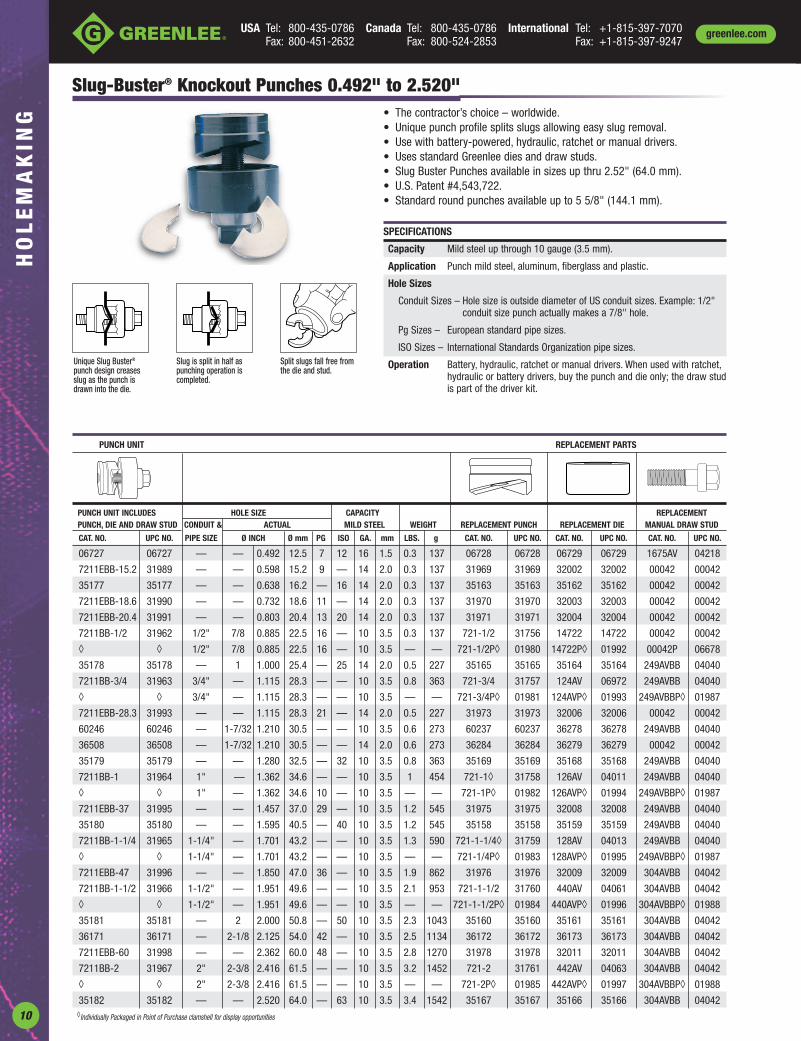
Slug-Buster® Knockout Punches 0.492" to 2.520"• The contractor’s choice – worldwide.• Unique punch profile splits slugs allowing easy slug removal.• Use with battery-powered, hydraulic, ratchet or manual drivers.• Uses standard Greenlee dies and draw studs.• Slug Buster Punches available in sizes up thru 2.52" (64.0 mm).• U.S. Patent #4,543,722.• Standard round punches available up to 5 5/8" (144.1 mm).
Unique Slug Buster®
punch design creasesslug as the punch isdrawn into the die.
Slug is split in half aspunching operation iscompleted.
Split slugs fall free fromthe die and stud.
SPECIFICATIONS
Capacity Mild steel up through 10 gauge (3.5 mm).
Application Punch mild steel, aluminum, fiberglass and plastic.
Hole Sizes
Conduit Sizes – Hole size is outside diameter of US conduit sizes. Example: 1/2"conduit size punch actually makes a 7/8" hole.
Pg Sizes – European standard pipe sizes.
ISO Sizes – International Standards Organization pipe sizes.
Operation Battery, hydraulic, ratchet or manual drivers. When used with ratchet,hydraulic or battery drivers, buy the punch and die only; the draw studis part of the driver kit.
PUNCH UNIT REPLACEMENT PARTS
PUNCH UNIT INCLUDES HOLE SIZE CAPACITY REPLACEMENTPUNCH, DIE AND DRAW STUD CONDUIT & ACTUAL MILD STEEL WEIGHT REPLACEMENT PUNCH REPLACEMENT DIE MANUAL DRAW STUD
CAT. NO. UPC NO. PIPE SIZE Ø INCH Ø mm PG ISO GA. mm LBS. g CAT. NO. UPC NO. CAT. NO. UPC NO. CAT. NO. UPC NO.
06727 06727 — — 0.492 12.5 7 12 16 1.5 0.3 137 06728 06728 06729 06729 1675AV 04218
7211EBB-15.2 31989 — — 0.598 15.2 9 — 14 2.0 0.3 137 31969 31969 32002 32002 00042 00042
35177 35177 — — 0.638 16.2 — 16 14 2.0 0.3 137 35163 35163 35162 35162 00042 00042
7211EBB-18.6 31990 — — 0.732 18.6 11 — 14 2.0 0.3 137 31970 31970 32003 32003 00042 00042
7211EBB-20.4 31991 — — 0.803 20.4 13 20 14 2.0 0.3 137 31971 31971 32004 32004 00042 00042
7211BB-1/2 31962 1/2" 7/8 0.885 22.5 16 — 10 3.5 0.3 137 721-1/2 31756 14722 14722 00042 00042
◊ ◊ 1/2" 7/8 0.885 22.5 16 — 10 3.5 — — 721-1/2P◊ 01980 14722P◊ 01992 00042P 06678
35178 35178 — 1 1.000 25.4 — 25 14 2.0 0.5 227 35165 35165 35164 35164 249AVBB 04040
7211BB-3/4 31963 3/4" — 1.115 28.3 — — 10 3.5 0.8 363 721-3/4 31757 124AV 06972 249AVBB 04040
◊ ◊ 3/4" — 1.115 28.3 — — 10 3.5 — — 721-3/4P◊ 01981 124AVP◊ 01993 249AVBBP◊ 01987
7211EBB-28.3 31993 — — 1.115 28.3 21 — 14 2.0 0.5 227 31973 31973 32006 32006 00042 00042
60246 60246 — 1-7/32 1.210 30.5 — — 10 3.5 0.6 273 60237 60237 36278 36278 249AVBB 04040
36508 36508 — 1-7/32 1.210 30.5 — — 14 2.0 0.6 273 36284 36284 36279 36279 00042 00042
35179 35179 — — 1.280 32.5 — 32 10 3.5 0.8 363 35169 35169 35168 35168 249AVBB 04040
7211BB-1 31964 1" — 1.362 34.6 — — 10 3.5 1 454 721-1◊ 31758 126AV 04011 249AVBB 04040
◊ ◊ 1" — 1.362 34.6 10 — 10 3.5 — — 721-1P◊ 01982 126AVP◊ 01994 249AVBBP◊ 01987
7211EBB-37 31995 — — 1.457 37.0 29 — 10 3.5 1.2 545 31975 31975 32008 32008 249AVBB 04040
35180 35180 — — 1.595 40.5 — 40 10 3.5 1.2 545 35158 35158 35159 35159 249AVBB 04040
7211BB-1-1/4 31965 1-1/4" — 1.701 43.2 — — 10 3.5 1.3 590 721-1-1/4◊ 31759 128AV 04013 249AVBB 04040
◊ ◊ 1-1/4" — 1.701 43.2 — — 10 3.5 — — 721-1/4P◊ 01983 128AVP◊ 01995 249AVBBP◊ 01987
7211EBB-47 31996 — — 1.850 47.0 36 — 10 3.5 1.9 862 31976 31976 32009 32009 304AVBB 04042
7211BB-1-1/2 31966 1-1/2" — 1.951 49.6 — — 10 3.5 2.1 953 721-1-1/2 31760 440AV 04061 304AVBB 04042
◊ ◊ 1-1/2" — 1.951 49.6 — — 10 3.5 — — 721-1-1/2P◊ 01984 440AVP◊ 01996 304AVBBP◊ 01988
35181 35181 — 2 2.000 50.8 — 50 10 3.5 2.3 1043 35160 35160 35161 35161 304AVBB 04042
36171 36171 — 2-1/8 2.125 54.0 42 — 10 3.5 2.5 1134 36172 36172 36173 36173 304AVBB 04042
7211EBB-60 31998 — — 2.362 60.0 48 — 10 3.5 2.8 1270 31978 31978 32011 32011 304AVBB 04042
7211BB-2 31967 2" 2-3/8 2.416 61.5 — — 10 3.5 3.2 1452 721-2 31761 442AV 04063 304AVBB 04042
◊ ◊ 2" 2-3/8 2.416 61.5 — — 10 3.5 — — 721-2P◊ 01985 442AVP◊ 01997 304AVBBP◊ 01988
35182 35182 — — 2.520 64.0 — 63 10 3.5 3.4 1542 35167 35167 35166 35166 304AVBB 04042◊Individually Packaged in Point of Purchase clamshell for display opportunities

11
USA Tel: 800-435-0786 Canada Tel: 800-435-0786 International Tel: +1-815-397-7070Fax: 800-451-2632 Fax: 800-524-2853 Fax: +1-815-397-9247
HO
LE
MA
KIN
Ggreenlee.com
Standard Round Knockout Punches 0.5" to 5.675"• Round Standard Metal Punch Units are complete units consisting of
punch, die and draw stud.• Use with battery-powered, hydraulic, ratchet or manual drivers.• Properly assembled through pilot holes, they will make clean, fast and
accurate holes.See page 25 for other sizes of standard round punches
SPECIFICATIONSCapacity Mild steel up through 10 gauge (3.5 mm).Application Punch mild steel, aluminum, fiberglass and plastic.Hole Sizes
Conduit Sizes – Hole size is outside diameter of US conduit sizes.Example: 1/2" conduit size punch actually makes a 7/8" hole.
Pg Sizes – European standard pipe sizes.ISO Sizes – International Standards Organization pipe sizes.
Operation Operate with battery-powered, hydraulic, ratchet or manual drivers.When used with battery-powered, hydraulic, or ratchet drivers buy thepunch and die only; the draw stud is part of the driver kit.
Punch
Die
Draw Stud
Bushing
Ball BearingNut
Every cut quick and clean ...Just tip it out.Slug falls free in die.
PUNCH UNIT REPLACEMENT PARTS
PUNCH KIT-INCLUDES HOLE SIZE CAPACITY REPLACEMENT REPLACEMENT
PUNCH, DIE & DRAW STUD CONDUIT & ACTUAL MILD STEEL WEIGHT REPLACEMENT PUNCH REPLACEMENT DIE DRAW STUD BALL BEARING NUT
CAT. NO. UPC NO. PIPE SIZE Ø INCH Ø mm PG ISO GA. mm LBS. g CAT. NO. UPC NO. CAT. NO. UPC NO. CAT. NO. UPC NO. CAT. NO. UPC NO.
730-1/2 02408 — 1/2 0.500 12.7 7 — 16 1.5 .1 46 1760AV 06996 1759AV 04235 1675AV 04218 — —
730-9/16 02433 — 9/16 0.563 14.3 — — 16 1.5 .1 46 1754AV 04230 1753AV 04229 1675AV 04218 — —
21115 21115 — — 0.598 15.2 9 — 14 2.0 .3 137 21316 21316 32002 32002 00042 00042 — —
730-5/8 02409 — 5/8 0.625 15.9 — — 16 1.5 .2 91 1742AV 04223 1743AV 04224 1675AV 04218 — —
35192 35192 — — 0.638 16.2 — 16 14 2.0 .3 137 35193 35193 35162 35162 00042 00042 — —
730BB-11/16 25340 — 11/16 0.688 17.5 — — 14 2.0 .3 137 1752AV 04228 1751AV 04227 00042 00042 — —
730EBB-18.6 18886 — — 0.732 18.6 11 — 14 2.0 .3 137 17700 17700 32003 32003 00042 00042 — —
730BB-3/4 20667 — 3/4 0.750 19.1 — — 14 2.0 .3 137 113AV 03998 114AV 03999 00042 00042 — —
730EBB - 20.4 18887 — — 0.803 20.4 13 20 14 2.0 .3 137 17697 17697 32004 32004 00042 00042 — —
730BB-13/16 20668 — 13/16 0.812 20.6 — — 14 2.0 .3 137 1745AV 04226 1744AV 04225 00042 00042 — —
730BB-15/16 25341 — 15/16 0.937 23.8 — — 14 2.0 .5 227 1762AV 04238 1761AV 04237 00042 00042 — —
730BB-1 20670 — 1 1.000 25.4 — 25 14 2.0 .5 227 87AV 03986 35164 35164 00042 00042 — —
730BB-1-1/16 25342 — 1-1/16 1.063 27.0 — — 14 2.0 .5 227 1763AV 04240 1764AV 04242 00042 00042 — —
730BB-1-1/8 20671 — 1-1/8 1.125 28.6 — — 14 2.0 .6 273 91AV 03990 92AV 03991 00042 00042 — —
36506 36506 — 1-7/32 1.210 30.5 — — 16 1.5 .6 273 36282 36282 36279 36279 00042 00042 — —
730BB-1-1/4 20673 — 1-1/4 1.250 31.8 — — 16 1.5 .7 318 117AV 04002 118AV 04003 00042 00042 — —
730BB-1-5/16 25344 — 1-5/16 1.313 33.4 — — 16 1.5 .7 318 1747AV 06587 1746AV 06586 00042 00042 — —
730BB-1-3/8 25427 — 1-3/8 1.375 34.9 — — 10 3.5 1.1 499 3205AV 04734 3206AV 04735 249AVBB 04040 — —
730BB-1-1/2 25428 — 1-1/2 1.500 38.1 — — 10 3.5 1.2 545 3207AV 04736 3208AV 07044 249AVBB 04040 — —
730BB-1-5/8 25349 — 1-5/8 1.625 41.3 — — 10 3.5 1.4 636 1794AV 04251 1793AV 04250 249AVBB 04040 — —
730BB-1-3/4 25350 — 1-3/4 1.750 44.5 — — 10 3.5 1.5 681 1816AV 04257 1815AV 04256 249AVBB 04040 — —
730BB-1-7/8 25351 — 1-7/8 1.875 47.6 — — 10 3.5 1.9 862 1791AV 04248 1792AV 04249 304AVBB 04042 — —
730BB-2-1/4 25360 — 2-1/4 2.250 57.2 — — 10 3.5 2.6 1180 437AV 04058 438AV 04059 304AVBB 04042 — —
730BB-2-1/2 20679 — 2-1/2 2.500 63.5 — 63 10 3.5 3 1361 1758AV 04234 1757AV 04233 304AVBB 04042 — —
730PBB-2-5/8 21214 — 2-5/8 2.625 66.7 — — 10 3.5 5.1 2314 1795AV 04252 1796AV 06997 1434AV 04188 1433AVBB 04187
730BB-2-3/4 25361 — 2-3/4 2.750 69.9 — — 10 3.5 4.8 2178 1790AV 04247 1789AV 04246 1434AV 04188 1433AVBB 04187
730MBB 25383 — — 2.781 70.6 — — 10 3.5 3.8 1724 730101A 02445 730100A 02443 304AVBB 04042 — —
738BB 19975 2-1/2" 2-7/8 2.914 74.0 — — 10 3.5 5 2268 1429AV 04175 1430AV 04177 1434AV 04188 1433AVBB 04187
730BB-3 25372 — 3 3.000 76.2 — — 10 3.5 6.1 2767 1821AV 04259 1820AV 04258 1434AV 04188 1433AVBB 04187
730TBB 25403 — 3-1/8 3.125 79.4 — — 10 3.5 6 2722 1798AV 06363 1797AV 06362 1434AV 04188 1433AVBB 04187
730EBB-82 18635 — — 3.228 82.0 — — 10 3.5 6.3 2858 18905 18905 18906 18906 1434AV 04188 1433AVBB 04187
739BB 19976 3" 3-1/2 3.539 89.9 — — 10 3.5 5.9 2677 1431AV 04180 1432AV 04183 1434AV 04188 1433AVBB 04187
730PBB-3-3/4 21216 — 3-3/4 3.750 95.3 — — 10 3.5 7.7 3493 4640AV 05265 4641AV 05266 1434AV 04188 1433AVBB 04187
741BB* 19977 3-1/2" 4 4.044 102.7 — — 10 3.5 10 4536 2982AV 04653 2981AV 04652 3026AV 04679 3036AVBB 04685
742BB* 19978 4" 4-1/2 4.544 115.4 — — 10 3.5 11.4 5172 2984AV 04655 2983AV 04654 3026AV 04679 3036AVBB 04685
730EBB-120* 21519 — — 4.724 120.0 — — 10 3.5 13 5897 21489 21489 21491 21491 3026AV 04679 3036AVBB 04685
743BB* 19980 5" 5-5/8 5.675 144.1 — — 10 3.5 19 8619 5135AV 05447 5136AV 05448 3026AV 04679 3036AVBB 04685
*CAT. NO. UPC NO. DESCRIPTION
3037AV O4686 Replacement Bushing for 3-1/2" (conduit hole size) and larger punches with manual operation

USA Tel: 800-435-0786 Canada Tel: 800-435-0786 International Tel: +1-815-397-7070Fax: 800-451-2632 Fax: 800-524-2853 Fax: +1-815-397-9247
greenlee.comH
OL
EM
AK
ING
12
• 1" Hex Ratchet Wrench allows use with both 3/8" (19.1 mm) and 3/4" (9.5 mm) draw studs.
• High-impact, rugged plastic carrying case.
Slug-Buster® Knockout Kit with Ratchet Wrench
CAPACITYMILD STEEL WEIGHT
CAT. NO. UPC NO. DESCRIPTION GA mm LBS. kg.
7238SB 34757 1/2" – 2" Conduit SizeSlug-Buster® Knockout Punch Kit 10 3.5 10 4.54
7238SB/34757 SLUG-BUSTER® KNOCKOUT PUNCH KIT INCLUDES
HOLE SIZE ACTUALCAT. NO. UPC NO. DESCRIPTION Ø INCH Ø mm PG34941 34941 Ratchet wrench – 1" Hex721-1/2 31756 1/2" Conduit Size Punch 7/8 .885 22.5 1614722 14722 1/2" Conduit Size Die 7/8 .885 22.5 16721-3/4 31757 3/4" Conduit Size Punch — 1.115 28.3 —124AV 06972 3/4" Conduit Size Die — 1.115 28.3 —721-1 31758 1" Conduit Size Punch — 1.362 34.6 —126AV 04011 1" Conduit Size Die — 1.362 34.6 —721-1-1/4 31759 1-1/4" Conduit Size Punch — 1.701 43.2 —128AV 04013 1-1/4" Conduit Size Die — 1.701 43.2 —721-1-1/2 31760 1-1/2" Conduit Size Punch — 1.951 49.6 —440AV 04061 1-1/2" Conduit Size Die — 1.951 49.6 —721-2 31761 2" Conduit Size Punch 2-3/8 2.416 61.5 —442AV 04063 2" Conduit Size Die 2-3/8 2.416 61.5 —00042 00042 Ball Bearing Draw Stud with 1" Hex Head–3/8" x 1-5/8"304AVBB 04042 Draw Stud–3/4" x 2-15/16"34758 34758 Plastic Case
7237BB
CAPACITYMILD STEEL WEIGHT
CAT. NO. UPC NO. DESCRIPTION GA mm LBS. kg.
7235BB 32013 1/2" - 1-1/4" Conduit Size Manual 10 3.5 2.7 1.2Slug-Buster® Knockout Punch Kit
7237BB 32014 1-1/2" and 2" Conduit Size Manual Slug-Buster® Knockout Punch Kit 10 3.5 5.2 2.4
7235BB/32013 SLUG-BUSTER® KNOCKOUT PUNCH KIT INCLUDES
HOLE SIZE ACTUALCAT. NO. UPC NO. DESCRIPTION Ø INCH Ø mm PG721-1/2 31756 1/2" Conduit Size Punch 7/8 .885 22.5 16
14722 14722 1/2" Conduit Size Die 7/8 .885 22.5 16
00042 00042 Draw Stud–3/8" x 1-5/8"
721-3/4 31757 3/4" Conduit Size Punch — 1.115 28.3 —
124AV 06972 3/4" Conduit Size Die — 1.115 28.3 —
721-1 31758 1" Conduit Size Punch — 1.362 34.6 —
126AV 04011 1" Conduit Size Die — 1.362 34.6 —
721–1-1/4 31759 1-1/4" Conduit Size Punch — 1.701 43.2 —
128AV 04013 1-1/4" Conduit Size Die — 1.701 43.2 —
249AVBB 04040 Draw Stud–3/4" x 2-1/8"
31880 31880 Plastic Case
7237BB/32014 SLUG-BUSTER® KNOCKOUT PUNCH KIT INCLUDES
HOLE SIZE ACTUALCAT. NO. UPC NO. DESCRIPTION Ø INCH Ø mm PG721-1-1/2 31760 1-1/2" Conduit Size Punch — 1.951 49.6 —
440AV 04061 1-1/2" Conduit Size Die — 1.951 49.6 —
721-2 31761 2" Conduit Size Punch 2-3/8 2.416 61.5 —
442AV 04063 2" Conduit Size Die 2-3/8 2.416 61.5 —
304AVBB 04042 Draw Stud–3/4" x 2-15/16"
32012 32012 Plastic Case
Slug-Buster® Manual Knockout Kits
• Assortment of commonly used Slug-Buster® knockoutpunches, packaged to meet the contractor’s needs.
• High-impact, rugged plastic carrying case.
7235BB

USA Tel: 800-435-0786 Canada Tel: 800-435-0786 International Tel: +1-815-397-7070Fax: 800-451-2632 Fax: 800-524-2853 Fax: +1-815-397-9247
HO
LE
MA
KIN
Ggreenlee.com
13
HOLE SIZE CAPACITY KIT CAT./UPC NO.ACTUAL MILD STEEL
CAT. NO. UPC NO. DESCRIPTION Ø INCH Ø mm PG ISO GA mm 36690 36691 36692 36693
31969 31969 Pg-9 Slug-Buster® Punch — 0.598 15.2 9 — 14 2.0 ✓ ✓
32002 32002 Pg-9 Die — 0.598 15.2 9 — 14 2.0 ✓ ✓
31970 31970 Pg-11 Slug-Buster® Punch — 0.732 18.6 11 — 14 2.0 ✓ ✓
32003 32003 Pg-11 Die — 0.732 18.6 11 — 14 2.0 ✓ ✓
31971 31971 Pg-13 Slug-Buster® Punch — 0.803 20.4 13 20 14 2.0 ✓ ✓ ✓ ✓
32004 32004 Pg-13 Die — 0.803 20.4 13 20 14 2.0 ✓ ✓ ✓ ✓
721-1/2 31756 Pg-16 Slug-Buster® Punch 7/8 0.885 22.5 16 — 10 3.5 ✓ ✓
14722 14722 Pg-16 Die 7/8 0.885 22.5 16 — 10 3.5 ✓ ✓
31973 31973 Pg-21 Slug-Buster® Punch — 1.115 28.3 21 — 14 2.0 ✓ ✓
32006 32006 Pg-21 Die — 1.115 28.3 21 — 14 2.0 ✓ ✓
36284 36284 30.5 mm Slug-Buster® Punch 1-7/32 1.210 30.5 — — 14 2.0 ✓ ✓
36279 36279 30.5 mm Die 1-7/32 1.210 30.5 — — 14 2.0 ✓ ✓
31975 31975 Pg-29 Slug-Buster® Punch — 1.457 37.0 29 — 10 3.5 ✓
32008 32008 Pg-29 Die — 1.457 37.0 29 — 10 3.5 ✓
31976 31976 Pg-36 Slug-Buster® Punch — 1.850 47.0 36 — 10 3.5 ✓
32009 32009 Pg-36 Die — 1.850 47.0 36 — 10 3.5 ✓
31978 31978 Pg-48 Slug-Buster® Punch — 2.362 60.0 48 — 10 3.5 ✓
32011 32011 Pg-48 Die — 2.362 60.0 48 — 10 3.5 ✓
35163 35163 ISO-16 Slug-Buster® Punch — 0.638 16.2 — 16 14 2.0 ✓ ✓
35162 35162 ISO-16 Die — 0.638 16.2 — 16 14 2.0 ✓ ✓
35165 35165 ISO-25 Slug-Buster® Punch 1 1.000 25.4 — 25 14 2.0 ✓ ✓
35164 35164 ISO-25 Die 1 1.000 25.4 — 25 14 2.0 ✓ ✓
35169 35169 ISO-32 Slug-Buster® Punch — 1.280 32.5 — 32 10 3.5 ✓ ✓
35168 35168 ISO-32 Die — 1.280 32.5 — 32 10 3.5 ✓ ✓
35158 35158 ISO-40 Slug-Buster® Punch — 1.595 40.5 — 40 10 3.5 ✓ ✓
35159 35159 ISO-40 Die — 1.595 40.5 — 40 10 3.5 ✓ ✓
35160 35160 ISO-50 Slug-Buster® Punch 2 2.000 50.8 — 50 10 3.5 ✓
35161 35161 ISO-50 Die 2 2.000 50.8 — 50 10 3.5 ✓
35167 35167 ISO-63 Slug-Buster® Punch 2-1/2 2.500 63.5 — 63 10 3.5 ✓
35166 35166 ISO-63 Die 2-1/2 2.500 63.5 — 63 10 3.5 ✓
249AVBB 04040 Draw Stud – 3/4" x 2-1/8" ✓
304AVBB 04042 Draw Stud – 3/4" x 2-15/16" ✓ ✓
36018 36018 Kwik Stepper® step bit 9.7 mm ✓ ✓ ✓ ✓
34941 34941 Ratchet wrench – 1" Hex ✓ ✓ ✓ ✓
00042 00042 Ball Bearing Drive Nut with 1" hex head, 3/8" x 3" ✓ ✓ ✓ ✓
36685 36685 Plastic Case ✓ ✓ ✓ ✓
36690
Draw
Stu
ds
and
Mis
c.Slug-Buster® Knockout Kit with Ratchet Wrench – Metric
• 1" (25.4 mm) hex ratchet wrench allows use with both 3/8" (9.5 mm)and 3/4" (19.1 mm) draw studs.
• 9.7 mm Kwik Stepper® step bit included.• High-impact, rugged plastic carrying case.
WEIGHTCAT. NO. UPC NO. DESCRIPTION LBS. kg.36690 36690 Pg-9 through 30.5 mm Manual Slug-Buster®
Metric Knockout Punch Kit 4.7 2.136691 36691 Pg-9 through Pg-48 and 30.5 mm
Manual Slug-Buster® Metric Knockout Punch Kit 9 4.136692 36692 ISO-16 through ISO-40 Manual Slug-Buster®
Metric Knockout Punch Kit 5.6 2.5
36693 36693 ISO-16 through ISO-63 Manual Slug-Buster®
Metric Knockout Punch Kit 9 4.1
Punc
hes
and
Dies

USA Tel: 800-435-0786 Canada Tel: 800-435-0786 International Tel: +1-815-397-7070Fax: 800-451-2632 Fax: 800-524-2853 Fax: +1-815-397-9247
greenlee.comH
OL
EM
AK
ING
14
Slug-Buster® Knockout Punch Kits for Ratchet/Hydraulic Drivers
• Packaged in carton for easy insertion into your existing case.• Replacement punch kits for battery-powered, hydraulic and ratchet
drivers.
HOLE SIZE CAPACITY- KIT CAT./UPC NO.CONDUIT & ACTUAL MILD STEEL 7216/ 7214E/ 7215E/
CAT. NO. UPC NO. DESCRIPTION PIPE SIZE Ø INCH Ø mm PG ISO GA mm 32017 32398 32803 35617 06892
721-1/2 31756 1/2" Conduit Size Punch 1/2" 7/8 .885 22.5 16 — 10 3.5 ✓ ✓ ✓
14722 14722 1/2" Conduit Size Die 1/2" 7/8 .885 22.5 16 — 10 3.5 ✓ ✓ ✓
721-3/4 31757 3/4" Conduit Size Punch 3/4" — 1.115 28.3 — — 10 3.5 ✓
124AV 06972 3/4" Conduit Size Die 3/4" — 1.115 28.3 — — 10 3.5 ✓
721-1 31758 1" Conduit Size Punch 1" — 1.362 34.6 — — 10 3.5 ✓
126AV 04011 1" Conduit Size Die 1" — 1.362 34.6 — — 10 3.5 ✓
721-1-1/4 31759 1-1/4" Conduit Size Punch 1-1/4" — 1.701 43.2 — — 10 3.5 ✓
128AV 04013 1-1/4" Conduit Size Die 1-1/4" — 1.701 43.2 — — 10 3.5 ✓
721-1-1/2 31760 1-1/2" Conduit Size Punch 1-1/2" — 1.951 49.6 — — 10 3.5 ✓
440AV 04061 1-1/2" Conduit Size Die 1-1/2" — 1.951 49.6 — — 10 3.5 ✓
721-2 31761 2" Conduit Size Punch 2" 2-3/8 2.416 61.5 — — 10 3.5 ✓
442AV 04063 2" Conduit Size Die 2" 2-3/8 2.416 61.5 — — 10 3.5 ✓
31969 31969 Pg-9 Punch — — .598 15.2 9 — 14 2.0 ✓ ✓
32002 32002 Pg-9 Die — — .598 15.2 9 — 14 2.0 ✓ ✓
31970 31970 Pg-11 Punch — — .732 18.6 11 — 14 2.0 ✓ ✓
32003 32003 Pg-11 Die — — .732 18.6 11 — 14 2.0 ✓ ✓
31971 31971 Pg-13 Punch — — .803 20.4 13 20 14 2.0 ✓ ✓ ✓ ✓
32004 32004 Pg-13 Die — — .803 20.4 13 20 14 2.0 ✓ ✓ ✓ ✓
31973 31973 Pg-21 Punch — — 1.115 28.3 21 — 14 2.0 ✓ ✓
32006 32006 Pg-21 Die — — 1.115 28.3 21 — 14 2.0 ✓ ✓
36284 36284 30.5 mm Punch — 1-7/32 1.210 30.5 — — 10 3.5 ✓ ✓
36279 36279 30.5 mm Die — 1-7/32 1.210 30.5 — — 10 3.5 ✓ ✓
31975 31975 Pg-29 Punch — — 1.457 37.0 29 — 10 3.5 ✓
32008 32008 Pg-29 Die — — 1.457 37.0 29 — 10 3.5 ✓
31976 31976 Pg-36 Punch — — 1.850 47.0 36 — 10 3.5 ✓
32009 32009 Pg-36 Die — — 1.850 47.0 36 — 10 3.5 ✓
31978 31978 Pg-48 Punch — — 2.362 60.0 48 — 10 3.5 ✓
32011 32011 Pg-48 Die — — 2.362 60.0 48 — 10 3.5 ✓
35163 35163 ISO-16 Punch — — 0.638 16.2 — 16 14 2.0 ✓ ✓
35162 35162 ISO-16 Die — — 0.638 16.2 — 16 14 2.0 ✓ ✓
35165 35165 ISO-25 Punch — 1 1.000 25.4 — 25 14 2.0 ✓ ✓
35164 35164 ISO-25 Die — 1 1.000 25.4 — 25 14 2.0 ✓ ✓
35169 35169 ISO-32 Punch — — 1.280 32.5 — 32 10 3.5 ✓ ✓
35168 35168 ISO-32 Die — — 1.280 32.5 — 32 10 3.5 ✓ ✓
35158 35158 ISO-40 Punch — — 1.595 40.5 — 40 10 3.5 ✓ ✓
35159 35159 ISO-40 Die — — 1.595 40.5 — 40 10 3.5 ✓ ✓
35160 35160 ISO-50 Punch — 2 2.000 50.8 — 50 10 3.5 ✓
35161 35161 ISO-50 Die — 2 2.000 50.8 — 50 10 3.5 ✓
35167 35167 ISO-63 Punch — — 2.520 64.0 — 63 10 3.5 ✓
35166 35166 ISO-63 Die — — 2.520 64.0 — 63 10 3.5 ✓
WEIGHTCAT. NO. UPC NO. DESCRIPTION LBS. kg.
7216 32017 1/2" - 2" Conduit Size Knockout Punch and Die Kit 5.5 2.5
7214E 32398 Pg-9 through 30.5 mm Slug-Buster® Pg Punch Kit 1.3 .6
7215E 32803 Pg-9 through Pg-48 and 30.5 mm Slug-Buster® 5.1 2.3 Pg Punch Kit
35617 35617 ISO-16 through ISO-40 Slug-Buster® ISO Punch Kit 1.6 .7
06892 06892 ISO-16 through ISO-63 Slug-Buster® ISO Punch Kit 5.5 2.5

USA Tel: 800-435-0786 Canada Tel: 800-435-0786 International Tel: +1-815-397-7070Fax: 800-451-2632 Fax: 800-524-2853 Fax: +1-815-397-9247
HO
LE
MA
KIN
Ggreenlee.com
15
The Slug-Buster® punches may not split the slug when used with this adapter, because of the small pilot hole.29451 sold separately. See page 37 for ordering information.
Gator-Plus™ Battery-Powered Knockout Punch Driver Kits• Punches a hole for 2" conduit (61.5 mm) in only 12 seconds.• Angled pistol grip allows easy one handed control and positioning.• Tool senses when the hole is completely punched and automatically shuts
off to prevent damage to the punch and die.• Develops 6.7 tons of hydraulic force, capable of punching up to 2"
conduit (61.5 mm) size holes in 10 gauge (3.5 mm) mild steel and 12 gauge (2.5 mm) stainless steel.
• Three choices of battery chargers – 115 volt, 220 volt, or 12 volt. Punchesapproximately 80 1/2" conduit size holes or 40 2" conduit size holes in10 gauge mild steel per battery charge.
• U.S. Patents #6,065,326, and #6,206,663LS6012A
SPECIFICATIONS
Weight (driver with battery only) 8.25 lbs. (3.7 kg)
Overall Length (ram retracted) 10.3 in. (262 mm)
Height 11.5 in. (292 mm)
Maximum Punch Force 6.7 tons (60 kN)
Maximum Round Punch Size 2.42 in. dia. (61.5 mm dia.)(in 10 gauge mild steel)
Maximum Square Punch Size 2-11/16 in. x 2-11/16 in.(in 10 gauge mild steel) (68.0 x 68.0 mm)
Maximum Rectangular 1.378 x 2.559 in.Punch Size (35.0 x 65.0 mm)
(in 10 gauge mild steel)
Maximum Ram Travel 0.87 in (22 mm)
Charging Time Approximately 1 hour
Battery Voltage 12 volts NiCd
WEIGHTCAT. NO. UPC NO. DESCRIPTION LBS. kg.
LS6011A 03557 Battery-powered driver with 115 volt charger,2 batteries, 2 draw studs, 1 adapter,and 1 spacer and case 23 10.4
LS6012A 03558 Battery-powered driver with 12 volt charger,2 batteries, 2 draw studs, 1 adapter,and 1 spacer and case 23 10.4
LS6022A 03559 Battery-powered driver with 220 volt charger,2 batteries, 2 draw studs, 1 adapter,and 1 spacer and case 23 10.4
LS6011B 04311 Battery-powered driver with 115 volt charger,2 batteries, 1/2" through 2" Slug-Buster®
conduit size punches, 2 draw studs, 1 adapter,and 1 spacer and case 27 12.2
LS6012B 04661 Battery-powered driver with 12 volt charger,2 batteries, 1/2" through 2" Slug-Buster®
conduit size punches, 2 draw studs, 1 adapter,and 1 spacer and case 27 12.2
LS6022B 04312 Battery-powered driver with 220 volt charger,2 batteries, 1/2" through 2" Slug-Buster®
conduit size punches, 2 draw studs, 1 adapter,and 1 spacer and case 27 12.2
See page 17 for complete parts list for all kits.
STEEL CAPACITIES FOR CONDUIT SIZES
STANDARD PUNCHES AND SLUG-BUSTERS® SLUG-SPLITTERS®
STUD AND 1/2" 3/4" 1-7/32" 1" 1-1/4" 1-1/2" 2" 1/2" 3/4" 1-7/32" 1" 1-1/4" 1-1/2" 2"ACCESSORIES CON. CON. CON. CON. CON. CON. CON. CON. CON. CON. CON. CON.
Ø 0.885" Ø 1.115" Ø 1.210" Ø 1.362" Ø 1.701" Ø 1.951" Ø 2.415" Ø 0.885" Ø 1.115" Ø 1.210" Ø 1.362" Ø 1.701" Ø 1.951" Ø 2.416"22.5mm 28.3mm 30.5mm 34.6mm 43.2mm 49.6mm 61.5mm 22.5mm 28.3mm 30.5mm 34.6mm 43.2mm 49.6mm 61.5mm
1614SS Draw Stud1924AA Spacer33967 Adapter
1924AA Spacer29451 7/16" Draw Stud
29451 7/16" Draw Stud
1924AA Spacer31872 3/4" Draw Stud
31872 3/4" Draw Stud
33967 Adapter
10 GA. (0.1345" [3.5 mm]) MILD STEEL 10 GA. (0.1345" [3.5 mm]) STAINLESS STEEL
12 GA. (0.1046" [2.5 mm]) STAINLESS STEEL 16 GA. (0.0598" [1.5 mm]) MILD STEEL AND 1/8" ALUMINUM
Elec
tron
ic C
onne
ctor
Pun
ches
RS-2
32,2
29,2
31,2
34,2
38
2
2
2
1
1
14 GA. (0.0747" [2 mm]) MILD STEEL

16
USA Tel: 800-435-0786 Canada Tel: 800-435-0786 International Tel: +1-815-397-7070Fax: 800-451-2632 Fax: 800-524-2853 Fax: +1-815-397-9247
greenlee.comH
OL
EM
AK
ING
The Slug-Buster® punches may not split the slug when used with this adapter, because of the small pilot hole.29451 sold separately. See page 37 for ordering information.
SPECIFICATIONS
Weight (driver) 8.25 lbs. (3.7 kg)
Overall Length (ram retracted) 10.3 in. (262 mm)
Height 11.5 in. (292 mm)
Maximum Punch Force 6.7 tons (60 kN)
Maximum Round Punch Size 2.42 in. dia. (61.5 mm dia.)(in 10 gauge mild steel)
Maximum Square Punch Size 2-11/16 in. x 2-11/16 in.(in 10 gauge mild steel) (68.0 x 68.0 mm)
Maximum Rectangular 1.378 x 2.559 in.Punch Size (35.0 x 65.0 mm)
(in 10 gauge mild steel)
Maximum Ram Travel 0.87 in (22 mm)
Operating Voltage 120V, 60Hz230V, 50Hz
WEIGHTCAT. NO. UPC NO. DESCRIPTION LBS. kg
CLS6011A 01496 Corded driver, 120 volts /60Hz, with 2 draw studs, 1 adapter, and 1 spacer and case. 23 10.4
CLS6022A 01497 Corded driver, 230 volts /50Hz, with 2 draw studs, 1 adapter, and 1 spacer and case. 23 10.4
CLS6011B 01498 Corded driver, 120 volts /60Hz, with 1/2" through 2" Slug-Buster conduit size punches, 2 draw studs, 1 adapter,and 1 spacer and case. 23 10.4
CLS6022B 01499 Corded driver, 230 volts /50Hz, with 1/2" through 2" Slug-Buster conduit size punches, 2 draw studs, 1 adapter,and 1 spacer and case. 27 12.2
See page 17 for complete parts list for all kits.
STEEL CAPACITIES FOR CONDUIT SIZES
STANDARD PUNCHES AND SLUG-BUSTERS® SLUG-SPLITTERS®
STUD AND 1/2" 3/4" 1-7/32" 1" 1-1/4" 1-1/2" 2" 1/2" 3/4" 1-7/32" 1" 1-1/4" 1-1/2" 2"ACCESSORIES CON. CON. CON. CON. CON. CON. CON. CON. CON. CON. CON. CON.
Ø 0.885" Ø 1.115" Ø 1.210" Ø 1.362" Ø 1.701" Ø 1.951" Ø 2.415" Ø 0.885" Ø 1.115" Ø 1.210" Ø 1.362" Ø 1.701" Ø 1.951" Ø 2.416"22.5mm 28.3mm 30.5mm 34.6mm 43.2mm 49.6mm 61.5mm 22.5mm 28.3mm 30.5mm 34.6mm 43.2mm 49.6mm 61.5mm
1614SS Draw Stud1924AA Spacer33967 Adapter
1924AA Spacer29451 7/16" Draw Stud
29451 7/16" Draw Stud
1924AA Spacer31872 3/4" Draw Stud
31872 3/4" Draw Stud
33967 Adapter
10 GA. (0.1345" [3.5 mm]) MILD STEEL 10 GA. (0.1345" [3.5 mm]) STAINLESS STEEL
12 GA. (0.1046" [2.5 mm]) STAINLESS STEEL 16 GA. (0.0598" [1.5 mm]) MILD STEEL AND 1/8" ALUMINUM
Elec
tron
ic C
onne
ctor
Pun
ches
RS-2
32,2
29,2
31,2
34,2
38
2
2
2
1
1
14 GA. (0.0747" [2 mm]) MILD STEEL
Gator-Plus™ Corded Knockout Punch Driver Kits• Punches a hole for 2" conduit (61.5 mm) in only 12 seconds.• Angled pistol grip allows easy one handed control and positioning.• Tool senses when the hole is completely punched and automatically shuts
off to prevent damage to the punch and die.• Develops 6.7 tons of hydraulic force, capable of punching up to 2"
conduit (61.5 mm) size holes in 10 gauge (3.5 mm) mild steel and 12 gauge (2.5 mm) stainless steel.
• Operates directly from 120V/60Hz or 230V/50Hz electrical outlets. Noneed to charge batteries or worry about running out of power.
• Equipped with 15 foot (5 m) cord. Can be used with extension cords.• U.S. Patents #6,065,326, and #6,206,663

USA Tel: 800-435-0786 Canada Tel: 800-435-0786 International Tel: +1-815-397-7070Fax: 800-451-2632 Fax: 800-524-2853 Fax: +1-815-397-9247
HO
LE
MA
KIN
Ggreenlee.com
10 GA. MILD STEEL 10 GA. STAINLESS STEEL
7625
WEIGHTCAT. NO. UPC NO. DESCRIPTION LBS. kg.
7625 25097 Driver, foot pump, steel case 37 17
7606SB 07173 Driver, foot pump, Slug-Buster® punches, dies and draw studs for 1/2" through 2" conduit, steel case 42 19
7610SB 07174 Driver, foot pump, Slug-Buster® punches, dies and draw studs for 1/2" through 4" conduit, steel case 60 27
STEEL CAPACITIES FOR CONDUIT SIZES
REQUIRED DRAW STUD STANDARD & SLUG-BUSTER® PUNCHES STANDARD SLUG-SPLITTERS®
AND ACCESSORIES 1/2" 3/4" 1" 1-1/4" 1-1/2" 2" 2-1/2" 3" 3-1/2" 4" 1/2" 3/4" 1" 1-1/4" 1-1/2" 2"
3/4" Stud (03294), 3/8" Stud (30043) & Spacers
3/4" Stud (03294), Long Spacer
3/4" Stud (03294), Short Spacer
3/4" Stud (03294)
3/4" Stud (03294), & Sleeve (03170)
7/16" Stud (29451)3/4" Stud (29452) & Spacer
Slug-Buster® Ram and Foot Pump Hydraulic Driver Kits• Foot operation frees both hands to operate punch.• Punches 10 times faster than wrench method.• Will also drive 751 Cable Cutter head.• Powerful 11 ton hydraulic ram.• Can be used with all standard round, Slug-Buster® and Slug-Splitter®
punch sizes.• Can be used with non-round punches (adapter may be required).
17
HOLE SIZE KIT CAT./UPC NO.CONDUIT LS6011A/03557 LS6011B/04311& PIPE ACTUAL LS6012A/03558 LS6012B/04661 CLS6011A CLS6011B
CAT. NO. UPC NO. DESCRIPTION SIZE Ø INCH Ø mm PG LS6022A/03559 LS6022B/04312 CLS6022A CLS6022B
721-1/2 31756 1/2" Conduit Size Slug-Buster® Punch 1/2" 7/8 0.885 22.5 16 ✓ ✓
14722 14722 1/2" Conduit Size Die 1/2" 7/8 0.885 22.5 16 ✓ ✓
721-3/4 31757 3/4" Conduit SizeSlug-Buster® Punch 3/4" — 1.115 28.3 21 ✓ ✓
124AV 06972 3/4" Conduit Size Die 3/4" — 1.115 28.3 21 ✓ ✓
721-1 31758 1" Conduit SizeSlug-Buster® Punch 1" — 1.362 34.6 — ✓ ✓
126AV 04011 1" Conduit Size Die 1" — 1.362 34.6 — ✓ ✓
721-1-1/4 31759 1-1/4" Conduit SizeSlug-Buster® Punch 1-1/4" 1-11/16 1.701 43.2 — ✓ ✓
128AV 04013 1-1/4" Conduit Size Die 1-1/4" 1-11/16 1.701 43.2 — ✓ ✓
721-1-1/2 31760 1-1/2" Conduit SizeSlug-Buster® Punch 1-1/2" 1-15/16 1.951 49.6 — ✓ ✓
440AV 04061 1-1/2" Conduit Size Die 1-1/2" 1-15/16 1.951 49.6 — ✓ ✓
721-2 31761 2" Conduit SizeSlug-Buster® Punch 2" 2-3/8 2.416 61.5 — ✓ ✓
442AV 04063 2" Conduit Size Die 2" 2-3/8 2.416 61.5 — ✓ ✓
1614SS 30043 Draw Stud–3/8" x 2-13/16" ✓ ✓ ✓ ✓
31872 31872 Draw Stud–3/4" x 4-1/8" ✓ ✓ ✓ ✓
1924AA 03248 Spacer-Short ✓ ✓ ✓ ✓
33967 33967 Stud Adapter–3/8" ✓ ✓ ✓ ✓
01686 01686 Metal Case ✓ ✓ ✓ ✓
Optional Accessories for LS6011B, LS6012B, and LS6022B (not included in kits)29451 29451 Draw Stud–7/16" x 4-1/2" for Slug Splitter Stainless Steel Punches
Draw
Stu
ds
and
Mis
c.Pu
nche
s an
d Di
esBattery-Powered Knockout Punch Driver Kits Parts List

18
USA Tel: 800-435-0786 Canada Tel: 800-435-0786 International Tel: +1-815-397-7070Fax: 800-451-2632 Fax: 800-524-2853 Fax: +1-815-397-9247
greenlee.comH
OL
EM
AK
ING
Ram and Foot Pump Kits Parts List
HOLE SIZE KIT CAT./UPC NO.CONDUIT& PIPE ACTUAL 7625/ 7606SB/ 7610SB/
CAT. NO. UPC NO. DESCRIPTION SIZE Ø INCH Ø mm PG 25097 07173 07174
721-1/2 31756 1/2" Conduit Size Slug-Buster® Punch 1/2" 7/8 0.885 22.5 16 1 1
14722 14722 1/2" Conduit Size Die 1/2" 7/8 0.885 22.5 16 1 1
721-3/4 31757 3/4" Conduit Size Slug-Buster® Punch 3/4" — 1.115 28.3 21 — 1 1
124AV 06972 3/4" Conduit Size Die 3/4" — 1.115 28.3 21 1 1
721-1 31758 1" Conduit Size Slug-Buster® Punch 1" — 1.362 34.6 — 1 1
126AV 04011 1" Conduit Size Die 1" — 1.362 34.6 — 1 1
721-1-1/4 31759 1-1/4" Conduit Size Slug-Buster® Punch 1-1/4" 1-11/16 1.701 43.2 — 1 1
128AV 04013 1-1/4" Conduit Size Die 1-1/4" 1-11/16 1.701 43.2 — 1 1
721-1-1/2 31760 1-1/2" Conduit Size Slug-Buster® Punch 1-1/2" 1-15/16 1.951 49.6 — 1 1
440AV 04061 1-1/2" Conduit Size Die 1-1/2" 1-15/16 1.951 49.6 — 1 1
721-2 31761 2" Conduit Size Slug-Buster® Punch 2" 2-3/8 2.416 61.5 — 1 1
442AV 04063 2" Conduit Size Die 2" 2-3/8 2.416 61.5 — 1 1
1429AV 04175 2-1/2" Conduit Size Punch 2-1/2" 2-7/8 2.914 74.0 — 1
1430AV 04177 2-1/2" Conduit Size Die 2-1/2" 2-7/8 2.914 74.0 — 1
1431AV 04180 3" Conduit Size Punch 3" 3-1/2 3.539 89.9 — 1
1432AV 04183 3" Conduit Size Die 3" 3-1/2 3.539 89.9 — 1
2982AV 04653 3-1/2" Conduit Size Punch 3-1/2" 4 4.044 102.7 — 1
2981AV 04652 3-1/2" Conduit Size Die 3-1/2" 4 4.044 102.7 — 1
2984AV 04655 4" Conduit Size Punch 4" 4-1/2 4.544 115.4 — 1
2983AV 04654 4" Conduit Size Die 4" 4-1/2 4.544 115.4 — 1
746 17091 (A) Ram (includes 1 ea. of items B, C, and D)
2113AA 03294 (B) Draw Stud–3/4" x 5-3/8" 1 1 1
54167 54167 (C) Female Coupler–1/4" 1 1 1
54168 54168 (D) Dust Plug 1 1 1
1557AA 03170 (F) Punch Sleeve 1 1 1
1614SS 30043 (G) Draw stud–3/8"x 2-13/16" 2 2 2
15908 15908 (H) Spacer Group (includes 1 ea. of items I, J, and K)
1924AA 03248 (I) Spacer-Short 1 1 1
1925AA 03249 (J) Spacer-Medium 1 1 1
1926AA 06904 (K) Spacer-Long 1 1 1
34410 34410 (L) Kwik Stepper® Step Bit 1/2" 1 1 1
1725 31353 (S) Hydraulic Foot Pump (includes 1 ea. – 54167 female coupler and 54168 dust plug) 1 1 1
37729 37729 (T) High Pressure Hose Unit – 1/4" x 10'; filled with hydraulic oil; (includes the following 2 items)
54169 54169 – Couplers 2 2 2
54170 54170 – Dust Caps 2 2 2
23955 23955 (U) Steel case 1 1 1
25094 25094 Tray 1 1 1
Draw
Stu
ds
and
Mis
c.Pu
nche
s an
d Di
es
A
B
C
D
F
GH L
S
U
DC
RAM AND FOOT PUMP HYDRAULIC DRIVER PARTS IDENTIFICATION(Match letters above to drawing.)
T
U
A
F
D B
HG L
S
C
C
D

19
USA Tel: 800-435-0786 Canada Tel: 800-435-0786 International Tel: +1-815-397-7070Fax: 800-451-2632 Fax: 800-524-2853 Fax: +1-815-397-9247
HO
LE
MA
KIN
Ggreenlee.com
Slug-Buster® Ram and Hand Pump Hydraulic Driver Kits• Fast, easy and simple to operate.• Compact design for field use on construction sites and maintenance jobs.• Punches 10 times faster than wrench method.• Will also drive 751 Cable Cutter head.• Can be used with all standard round, Slug-Buster® and Slug-Splitter®
punch sizes.• Can be used with non-round punches (adapter may be required).• 3-foot hose.• Powerful 11-ton hydraulic ram.
WEIGHTCAT. NO. UPC NO. DESCRIPTION LBS. kg.7646 15906 Driver, hand pump, draw studs, adapter, spacers,
Kwik Stepper® Step Bit and plastic case 20 9.17306SB 34360 Driver, hand pump, Slug-Buster® punches, dies
and draw studs for 1/2" through 2" conduit, adapter,spacers, Kwik Stepper® Step Bit and plastic case 24 10.9
7310SB 34361 Driver, hand pump, Slug-Buster® punches, dies and draw studs for 1/2" through 2" and 2-1/2"through 4" standard conduit size punches, dies and draw studs, adapter, spacers, Kwik Stepper® StepBit and steel case 54 24.5
7646PgSB 32799 Metric – Driver, Slug-Buster® Pg punches, dies and draw studs for 15.2 mm through 60.0 mm,adapter, spacers, Kwik Stepper® Step Bit and plastic case 24 10.9
38520 38520 Driver, hand pump, Slug-Buster® punches and drawstuds for 1/2" through 3" and 4" conduit, adapter,spacers, Kwik Stepper® Step Bit and steel case 48 21.8
7646
STEEL CAPACITIES FOR CONDUIT SIZES
REQUIRED DRAW STUD STANDARD & SLUG-BUSTER PUNCHES STANDARD SLUG-SPLITTERS®
AND ACCESSORIES 1/2" 3/4" 1" 1-1/4" 1-1/2" 2" 2-1/2" 3" 3-1/2" 4" 1/2" 3/4" 1" 1-1/4" 1-1/2" 2"3/4" Stud (03294),3/8" Stud (30043) & Spacers3/4" Stud (03294),Long Spacer3/4" Stud (03294),Short Spacer3/4" Stud (03294)
3/4" Stud (03294),& Sleeve (03170)7/16" Stud(29451)3/4" Stud (29452)& Spacer
A
BF
GH
J
L
M
N
R
IK
RAM AND HAND PUMP HYDRAULIC DRIVER PARTS IDENTIFICATION
KEY CAT./UPC NO. DESCRIPTION
A 746 / 17091 Ram (includes Item B)
B 2113AA / 03294 Draw Stud–3/4" x 5-3/8"
F 1557AA / 03170 Punch Sleeve
G 1614SS / 30043 Draw Stud–3/8" x 2-13/16"
H 15908 Spacer Group (includes Items I, J and K)
I 1924AA / 03248 Spacer-Short
J 1925AA / 03249 Spacer-Medium
K 1926AA / 06904 Spacer-Long
L 34410 Kwik Stepper® Step Bit 1/2"
M 767 / 13284 Hydraulic Hand Pump
N 06302 / 06302 High Pressure Hose–1/4" x 3'
R 30206 Plastic Case
10 GA. MILD STEEL 10 GA. STAINLESS STEEL
A
B
FG
HL
R
M
N
K J I

20
USA Tel: 800-435-0786 Canada Tel: 800-435-0786 International Tel: +1-815-397-7070Fax: 800-451-2632 Fax: 800-524-2853 Fax: +1-815-397-9247
greenlee.comH
OL
EM
AK
ING
Ram and Hand Pump Kits Parts List
HOLE SIZE KIT CAT./UPC NO.CONDUIT& PIPE ACTUAL 7646/ 7306SB/ 7310SB/ 7646PGSB/
CAT. NO. UPC NO. DESCRIPTION SIZE Ø INCH Ø mm PG ISO 15906 34360 34361 32799 38520
721-1/2 31756 1/2" Conduit Size Slug-Buster® Punch 1/2" 7/8 0.885 22.5 16 — 1 1 1 1
14722 14722 1/2" Conduit Size Die 1/2" 7/8 0.885 22.5 16 — 1 1 1 1
721-3/4 31757 3/4" Conduit Size Slug-Buster® Punch 3/4" — 1.115 28.3 21 — 1 1 1
124AV 06972 3/4" Conduit Size Die 3/4" — 1.115 28.3 21 — 1 1 1
721-1 31758 1" Conduit Size Slug-Buster® Punch 1" — 1.362 34.6 — — 1 1 1
126AV 04011 1" Conduit Size Die 1" — 1.362 34.6 — — 1 1 1
721-1-1/4 31759 1-1/4" Conduit Size Slug-Buster® Punch 1-1/4" 1-11/16 1.701 43.2 — — 1 1 1
128AV 04013 1-1/4" Conduit Size Die 1-1/4" 1-11/16 1.701 43.2 — — 1 1 1
721-1-1/2 31760 1-1/2" Conduit Size Slug-Buster® Punch 1-1/2" 1-15/16 1.951 49.6 — — 1 1 1
440AV 04061 1-1/2" Conduit Size Die 1-1/2" 1-15/16 1.951 49.6 — — 1 1 1
721-2 31761 2" Conduit Size Slug-Buster® Punch 2" 2-3/8 2.416 61.5 — — 1 1 1
442AV 04063 2" Conduit Size Die 2" 2-3/8 2.416 61.5 — — 1 1 1
1429AV 04175 2-1/2" Conduit Size Punch 2-1/2" 2-7/8 2.914 74.0 — — 1 1
1430AV 04177 2-1/2" Conduit Size Die 2-1/2" 2-7/8 2.914 74.0 — — 1 1
1431AV 04180 3" Conduit Size Punch 3" 3-1/2 3.539 89.9 — — 1 1
1432AV 04183 3" Conduit Size Die 3" 3-1/2 3.539 89.9 — — 1 1
2982AV 04653 3-1/2" Conduit Size Punch 3-1/2" 4 4.044 102.7 — — 1
2981AV 04652 3-1/2" Conduit Size Die 3-1/2" 4 4.044 102.7 — — 1
2984AV 04655 4" Conduit Size Punch 4" 4-1/2 4.544 115.4 — — 1 1
2983AV 04654 4" Conduit Size Die 4" 4-1/2 4.544 115.4 — — 1 1
31969 31969 Slug-Buster® Punch — — 0.598 15.2 9 — 1
32002 32002 Die — — 0.598 15.2 9 — 1
31970 31970 Slug-Buster® Punch — — 0.732 18.6 11 — 1
32003 32003 Die — — 0.732 18.6 11 — 1
31971 31971 Slug-Buster® Punch — — 0.803 20.4 13 20 1
32004 32004 Die — — 0.803 20.4 13 20 1
31973 31973 Slug-Buster® Punch 3/4" — 1.115 28.3 21 — 1
32006 32006 Die 3/4" — 1.115 28.3 21 — 1
36284 36284 30.5 mm Slug-Buster® Punch — 1-7/32 1.210 30.5 — — 1
36279 36279 30.5 mm Die — 1-7/32 1.210 30.5 — — 1
31975 31975 Slug-Buster® Punch — — 1.457 37.0 29 — 1
32008 32008 Die — — 1.457 37.0 29 — 1
31976 31976 Slug-Buster® Punch — — 1.850 47.0 36 — 1
32009 32009 Die — — 1.850 47.0 36 — 1
31978 31978 Slug-Buster® Punch — — 2.362 60.0 48 — 1
32011 32011 Die — — 2.362 60.0 48 — 1
746 17091 Ram (includes following item) 1 1 1 1 1
2113AA 03294 – Draw Stud–3/4" x 5-3/8" 1 1 1 1 1
1557AA 03170 Punch Sleeve 1 1 1 1 1
1614SS 30043 Draw Stud–3/8"x 2-13/16" 2 2 2 2 2
15908 15908 Spacer Group (includes 1 ea. of the following 3 items)
1924AA 03248 – Spacer-Short 1 1 1 1 1
1925AA 03249 – Spacer-Medium 1 1 1 1 1
1926AA 06904 – Spacer-Long 1 1 1 1 1
34410 34410 Kwik Stepper® Step Bit 1/2" 1 1 1 1 1
767 13284 Hydraulic Hand Pump 1 1 1 1 1
06302 06302 High Pressure Hose–1/4" x 3' 1 1 1 1
30206 30206 Plastic Case 1 1 1
18402 18402 Steel Case 1 1
25094 25094 Punch Tray 1
Punc
hes
and
Dies
Draw
Stu
ds
and
Mis
c.

21
7806SBQuick Draw Kit
7906SBQuick Draw 90 Kit
USA Tel: 800-435-0786 Canada Tel: 800-435-0786 International Tel: +1-815-397-7070Fax: 800-451-2632 Fax: 800-524-2853 Fax: +1-815-397-9247
HO
LE
MA
KIN
Ggreenlee.com
Quick Draw® Hydraulic Punch Driver and KitsThe Quick Draw®, Quick Draw 90®, and Quick Draw® Flex feature:• Compact, lightweight design for portability and fast, easy one-person
operation.• Develops 8 tons of hydraulic force for easy punching, even in 10-gauge
stainless steel depending on individual punch capacities.• Quick Draw® is perfect for fast, straight-on front panel punching.• Quick Draw 90®’s right angle driver head rotates over 180 degrees for
maximum flexibility in tight working areas.• Quick Draw® Flex allows unlimited driver orientation to simplify access to
work area.• Can be used with non-round punches within the capacity of the tool
(adapter may be required).
WEIGHTCAT. NO. UPC NO. DESCRIPTION LBS. kg.7704SB 10475 Quick Draw® Flex Driver, 2 draw studs, 12.1 5.5
1 adapters, 1 spacer and case7706SB 10476 Standard – Quick Draw® Flex Driver, 1/2" through 17.3 7.9
2" Slug Buster® conduit size punches and dies 2 draw studs, 1 adapter, 1 spacer and case
7804SB 34292 Quick Draw® Driver, 2 draw studs, 1 adapter, 10 4.51 spacer and case
7806SB 34293 Standard – Quick Draw® Driver, 1/2" through 2" 14 6.4Slug Buster® conduit size punches and dies 2 draw studs, 1 adapter, 1 spacer and case
7804E 34291 Metric – Quick Draw® Driver, 2 draw studs, 9.4 4.3 1 adapter, 1 spacer and case
7804ESB 35611 Metric – Quick Draw® Driver, Slug-Buster® Pg 10.3 4.7punches and dies 15.2 mm through 30.5 mm,2 draw studs, 1 adapter, 1 spacer and case
7804ISO 35614 Metric – Quick Draw® Driver, Slug-Buster® 11.4 5.2ISO punches and dies 16.2 mm through 40.5 mm,2 draw studs, 1 adapter, 1 spacer and case
7904SB 33794 Quick Draw 90® Driver, 2 draw studs, 10 4.51 adapter, 1 spacer and case
7906SB 34300 Quick Draw 90® Driver, 1/2" through 2" Slug- 14 6.4Buster® conduit size punches and dies, draw studs, 1 adapter, 1 spacer and case
7904E 34299 Metric – Quick Draw 90® Driver, 2 draw studs, 11 5.01 adapter, 1 spacer and case
7904ESB 35615 Metric – Quick Draw 90® Driver, Slug-Buster® 11 5.0Pg punches and dies 15.2 mm through 30.5 mm,2 draw studs, 1 adapter, 1 spacer and case
7904ISO 35616 Metric – Quick Draw 90® Driver, Slug-Buster® 12.2 5.5ISO punches and dies 16.2 mm through 40.5 mm,2 draw studs, 1 adapter, 1 spacer and case
See next page for complete parts list for all kits.
STEEL CAPACITIES FOR CONDUIT SIZES
STANDARD PUNCHES AND SLUG-BUSTERS® SLUG-SPLITTERS®
REQUIREDDRAW STUD AND 1/2" 3/4" 1-7/32" 1" 1-1/4" 1-1/2" 2" 1/2" 3/4" 1-7/32" 1-1/4"ACCESSORIES OILTIGHT OILTIGHT
3/8" Draw Stud
Spacer & 7/16" Draw Stud
Adapter & 7/16" Draw Stud
Spacer & 3/4" Draw Stud
3/4" Draw Stud
10 GA. MILD STEEL 14 GA. MILD STEEL 10 GA. STAINLESS STEEL
7706 Flex Driver

22
USA Tel: 800-435-0786 Canada Tel: 800-435-0786 International Tel: +1-815-397-7070Fax: 800-451-2632 Fax: 800-524-2853 Fax: +1-815-397-9247
greenlee.comH
OL
EM
AK
ING
Parts List for Quick Draw®, Quick Draw 90® and Quick Draw® Flex Kits
HOLE SIZE KIT CAT./UPC NO.
CONDUIT
& PIPE ACTUAL 7704SB/ 7706SB/ 7804E/ 7804ESB/7804ISO/ 7804SB/ 7806SB/ 7904E/ 7904ESB/7904ISO/ 7904SB/ 7906SB/
CAT. NO. UPC NO. DESCRIPTION SIZE Ø INCH Ø mm PG ISO 10475 10476 34291 35611 35614 34292 34293 34299 35615 35616 33794 34300
721-1/2 31756 1/2" Conduit Size
Slug-Buster® Punch 1/2" 7/8 0.885 22.5 16 — ✓ ✓ ✓
14722 14722 1/2" Conduit Size Die 1/2" 7/8 0.885 22.5 16 — ✓ ✓ ✓
721-3/4 31757 3/4" Conduit Size
Slug-Buster® Punch 3/4" — 1.115 28.3 21 — ✓ ✓ ✓
124AV 06972 3/4" Conduit Size Die 3/4" — 1.115 28.3 21 — ✓ ✓ ✓
721-1 31758 1" Conduit Size
Slug-Buster® Punch 1" — 1.362 34.6 — — ✓ ✓ ✓
126AV 04011 1" Conduit Size Die 1" — 1.362 34.6 — — ✓ ✓ ✓
721-1-1/4 31759 1-1/4" Conduit Size
Slug-Buster® Punch 1-1/4" 1-11/16 1.701 43.2 — — ✓ ✓ ✓
128AV 04013 1-1/4" Conduit Size Die 1-1/4" 1-11/16 1.701 43.2 — — ✓ ✓ ✓
721-1-1/2 31760 1-1/2" Conduit Size
Slug-Buster® Punch 1-1/2" 1-15/16 1.951 49.6 — — ✓ ✓ ✓
440AV 04061 1-1/2" Conduit Size Die 1-1/2" 1-15/16 1.951 49.6 — — ✓ ✓ ✓
721-2 31761 2" Conduit Size
Slug-Buster® Punch 2" 2-3/8 2.416 61.5 — — ✓ ✓ ✓
442AV 04063 2" Conduit Size Die 2" 2-3/8 2.416 61.5 — — ✓ ✓ ✓
31969 31969 Slug-Buster® Punch — — 0.598 15.2 9 — ✓ ✓
32002 32002 Die — — 0.598 15.2 9 — ✓ ✓
31970 31970 Slug-Buster® Punch — — 0.732 18.6 11 — ✓ ✓
32003 32003 Die — — 0.732 18.6 11 — ✓ ✓
31971 31971 Slug-Buster® Punch — — 0.803 20.4 13 20 ✓ ✓ ✓ ✓
32004 32004 Die — — 0.803 20.4 13 20 ✓ ✓ ✓ ✓
721-1/2 31756 Slug-Buster® Punch 1/2" 7/8 0.885 22.5 16 — ✓ ✓
14722 14722 Die 1/2" 7/8 0.885 22.5 16 — ✓ ✓
31973 31973 Slug-Buster® Punch 3/4" — 1.115 28.3 21 — ✓ ✓
32006 32006 Die 3/4" — 1.115 28.3 21 — ✓ ✓
36284 36284 30.5 mm Slug-Buster® — 1-7/32 1.210 30.5 — — ✓ ✓
Punch
36279 36279 30.5 mm Die — 1-7/32 1.210 30.5 — — ✓ ✓
35163 35163 ISO-16 Slug-Buster® — — 0.638 16.2 — 16 ✓
Punch
35162 35162 ISO-16 Die — — 0.638 16.2 — 16 ✓ ✓
35165 35165 ISO-25 Slug-Buster® — 1 1.000 25.4 — 25 ✓
Punch
35164 35164 ISO-25 Die — 1 1.000 25.4 — 25 ✓ ✓
35169 35169 ISO-32 Slug-Buster® — — 1.280 32.5 — 32 ✓
Punch
35168 35168 ISO-32 Die — — 1.280 32.5 — 32 ✓ ✓
35158 35158 ISO-40 Slug-Buster® — — 1.595 40.5 — 40 ✓
Punch
35159 35159 ISO-40 Die — — 1.595 40.5 — 40 ✓ ✓
34288 34288 Quick Draw® Hydraulic Punch Driver ✓ ✓ ✓ ✓ ✓
33786 33786 Quick Draw 90®
Hydraulic Punch Driver ✓ ✓ ✓ ✓ ✓
10383 10383 Quick Draw® Flex Driver ✓ ✓
1614SS 30043 Draw Stud–3/8" x 2-13/16" ✓ ✓ ✓ ✓ ✓ ✓ ✓ ✓ ✓ ✓ ✓ ✓
31872 31872 Draw Stud–3/4" x 4-1/8" ✓ ✓ ✓ ✓ ✓ ✓ ✓ ✓ ✓ ✓ ✓ ✓
1924AA 03248 Spacer-Short ✓ ✓ ✓ ✓ ✓ ✓ ✓ ✓ ✓ ✓ ✓ ✓
33967 33967 Stud Adapter–3/8" ✓ ✓ ✓ ✓ ✓ ✓ ✓ ✓ ✓ ✓ ✓ ✓
35202 35202 Plastic Case ✓ ✓ ✓ ✓ ✓ ✓
34983 34983 Plastic Case ✓ ✓ ✓ ✓
10391 10391 Plastic Case ✓ ✓
Optional Accessories for 7806SB, 7804E, 7804ESB, 7804ISO, 7906SB, 7904E, 7904ESB and 7904ISO Kits (not included in kits)
29451 29451 7/16" (11.1 mm) Stainless Steel Draw Stud
Punc
hes
and
Dies
Draw
Stu
ds a
nd M
isc.

23
USA Tel: 800-435-0786 Canada Tel: 800-435-0786 International Tel: +1-815-397-7070Fax: 800-451-2632 Fax: 800-524-2853 Fax: +1-815-397-9247
HO
LE
MA
KIN
Ggreenlee.com
Slug-Buster® Ratchet Punch Driver Kits
• Time saving ball bearing head punches faster than wrench method.• Requires less than half the force of conventional ratchet drivers.• Punches up through 10 gauge (3.5 mm) mild steel with Greenlee®
Standard and Slug-Buster® punches; and 16 gauge (1.5 mm) stainlesssteel with Greenlee Slug-Splitter® punches.
• Ratchet action allows for use in confined areas.• Unique design eliminates stud rotation during punching –
lowers the strain on studs.• Steel carrying case.1906SB
WEIGHTCAT. NO. UPC NO. DESCRIPTION LBS. kg.
1904 30216 Basic High Leverage Ratchet Driver with four draw studs and case 14 6.4
1906SB 34357 High Leverage Ratchet Driver with 1/2" through 2" Slug-Buster® conduit size punches,dies, draw studs and case 20 9.1
HOLE SIZE KIT CAT./UPC NO.CONDUIT CAPACITY& PIPE ACTUAL MILD STEEL 1904/ 1906SB/
CAT. NO. UPC NO. DESCRIPTION SIZE Ø INCH Ø mm GA mm 30216 34357
721-1/2 31756 1/2" Conduit Size Slug-Buster® Punch 1/2" 7/8 0.885 22.5 10 3.5 ✓
14722 14722 1/2" Conduit Size Die 1/2" 7/8 0.885 22.5 10 3.5 ✓
721-3/4 31757 3/4" Conduit Size Slug-Buster® Punch 3/4" — 1.115 28.3 10 3.5 ✓
124AV 06972 3/4" Conduit Size Die 3/4" — 1.115 28.3 10 3.5 ✓
721-1 31758 1" Conduit Size Slug-Buster® Punch 1" — 1.362 34.6 10 3.5 ✓
126AV 04011 1" Conduit Size Die 1" — 1.362 34.6 10 3.5 ✓
721-1-1/4 31759 1-1/4" Conduit Size Slug-Buster® Punch 1-1/4" 1-11/16 1.701 43.2 10 3.5 ✓
128AV 04013 1-1/4" Conduit Size Die 1-1/4" 1-11/16 1.701 43.2 10 3.5 ✓
721-1-1/2 31760 1-1/2" Conduit Size Slug-Buster® Punch 1-1/2" 1-15/16 1.951 49.6 10 * 3.5 ✓
440AV 04061 1-1/2" Conduit Size Die 1-1/2" 1-15/16 1.951 49.6 10 * 3.5 ✓
721-2 31761 2" Conduit Size Slug-Buster® Punch 2" 2-3/8 2.416 61.5 10 * 3.5 ✓
442AV 04063 2" Conduit Size Die 2" 2-3/8 2.416 61.5 10 * 3.5 ✓
12097 12097 Draw Stud – 3/8" x 2-15/16" ✓ ✓
12098 12098 Draw Stud – 3/4" x 3-15/16" ✓ ✓
12099 12099 Draw Stud – 3/4" x 4-3/4" ✓ ✓
30227 30227 Draw Stud – 7/16" x 3-5/8" ✓
30228 30228 Steel Case ✓ ✓
20495 20495 Ratchet wrench only ✓ ✓
30225 30225 Handle ✓ ✓
Punc
hes
and
Dies
Draw
Stu
ds
and
Mis
c.

USA Tel: 800-435-0786 Canada Tel: 800-435-0786 International Tel: +1-815-397-7070Fax: 800-451-2632 Fax: 800-524-2853 Fax: +1-815-397-9247
greenlee.comH
OL
EM
AK
ING
24
Wrench Sold Separately
735BB
737BB
• Assortment of commonly used round standard knockoutpunches, packaged to meet the contractor’s needs.
• High-impact, rugged plastic carrying case.
7304
CAPACITYMILD STEEL WEIGHT
CAT. NO. UPC NO. DESCRIPTION GA mm LBS. kg.735BB 19973 1/2" - 1-1/4" Conduit Size Manual
Round Standard Knockout Punch Kit 10 3.5 2.5 1.1737BB 19974 1-1/2" - 2" Conduit Size Manual
Round Standard Knockout Punch Kit 10 3.5 4.4 2.07304 02815 Standard punches and dies (no draw
studs) for 2-1/2" through 4" conduit,in plastic case 10 3.5 21 9.5
735BB/19973 KNOCKOUT PUNCH KIT INCLUDESHOLE SIZE
ACTUALCAT. NO. UPC NO. DESCRIPTION Ø INCH Ø mm721-1/2 31756 1/2" Conduit Size Slug-Buster® Punch 7/8 0.885 22.514722 14722 1/2" Conduit Size Die 7/8 0.885 22.500042 00042 3/8" x 1-9/16" Draw Stud123AV 04008 3/4" Conduit Size Punch — 1.115 28.3124AV 06972 3/4" Conduit Size Die — 1.115 28.3125AV 04010 1" Conduit Size Punch — 1.362 34.6126AV 04011 1" Conduit Size Die — 1.362 34.6127AV 06974 1-1/4" Conduit Size Punch 1-11/16 1.701 43.2128AV 04013 1-1/4" Conduit Size Die 1-11/16 1.701 43.2249AVBB 04040 3/4" x 2-1/8" Draw Stud31880 31880 Plastic Case
737BB/19974 KNOCKOUT PUNCH KIT INCLUDESHOLE SIZE
ACTUALCAT. NO. UPC NO. DESCRIPTION Ø INCH Ø mm439AV 06978 1-1/2" Conduit Size Punch 1-15/16 1.951 49.6440AV 04061 1-1/2" Conduit Size Die 1-15/16 1.951 49.6441AV 04062 2" Conduit Size Punch 2-3/8 2.416 61.5442AV 04063 2" Conduit Size Die 2-3/8 2.416 61.5304AVBB 04042 3/4" x 2-15/16" Draw Stud32012 32012 Plastic Case
7304/02815 KNOCKOUT PUNCH KIT INCLUDESHOLE SIZE
ACTUALCAT. NO. UPC NO. DESCRIPTION Ø INCH Ø mm1429AV 04175 2-1/2" Conduit Size Punch 2-7/8 2.914 74.01430AV 04177 2-1/2" Conduit Size Die 2-7/8 2.914 74.01431AV 04180 3" Conduit Size Punch 3-1/2 3.539 89.91432AV 04183 3" Conduit Size Die 3-1/2 3.539 89.92982AV 04978 3-1/2" Conduit Size Punch 4 4.044 102.72981AV 04652 3-1/2" Conduit Size Die 4 4.044 102.72984AV 04655 4" Conduit Size Punch 4-1/2 4.544 115.42983AV 04654 4" Conduit Size Die 4-1/2 4.544 115.430236 30236 Plastic Case
NOTE: See Round Standard Knockout Punch Units on page 11 or 25 for list of individual punch units
Standard Round Manual Knockout Punch Kits

USA Tel: 800-435-0786 Canada Tel: 800-435-0786 International Tel: +1-815-397-7070Fax: 800-451-2632 Fax: 800-524-2853 Fax: +1-815-397-9247
HO
LE
MA
KIN
Ggreenlee.com
25
PUNCH UNIT REPLACEMENT PARTS
PUNCH KIT-INCLUDES HOLE SIZE CAPACITY REPLACEMENT
PUNCH, DIE & DRAW STUD CONDUIT & ACTUAL MILD STEEL WEIGHT REPLACEMENT PUNCH REPLACEMENT DIE DRAW STUD
CAT. NO. UPC NO. PIPE SIZE Ø INCH Ø mm PG ISO GA. mm LBS. g CAT. NO. UPC NO. CAT. NO. UPC NO. CAT. NO. UPC NO.
71BB 22563 1/2" 7/8 0.885 22.5 16 — 10 3.5 .4 182 121AV 04006 14722 14722 00042 00042
72BB 22564 3/4" — 1.115 28.3 21 — 10 3.5 .9 409 123AV 04008 124AV 06972 249AVBB 04040
36910 36910 3/4" — 1.115 28.3 21 — 14 2.0 .6 273 36882 36882 32006 32006 00042 00042
24476 24476 — — 1.280 32.5 — 32 10 3.5 1 454 24459 24459 35168 35168 249AVBB 04040
73BB 22565 1" — 1.362 34.6 — — 10 3.5 1.1 499 125AV 04010 126AV 04011 249AVBB 04040
730EBB-37 18890 — — 1.457 37.0 29 — 10 3.5 1 454 18331 18331 32008 32008 249AVBB 04040
24477 24477 — — 1.595 40.5 — 40 10 3.5 1.3 590 24462 24462 35159 35159 249AVBB 04040
74BB 22566 1-1/4 1-11/16 1.701 43.2 — — 10 3.5 1.4 636 127AV 06974 128AV 04013 249AVBB 04040
730EBB-47 18891 — — 1.850 47.0 — — 10 3.5 1.7 772 17687 17687 32009 32009 304AVBB 04042
75BB 22567 1-1/2" 1-15/16 1.951 49.6 — — 10 3.5 2 908 439AV 06978 440AV 04061 304AVBB 04042
730BB-2 20676 — 2 2.000 50.8 — 50 10 3.5 1.9 862 1756AV 04232 35161 35161 304AVBB 04042
730BB-2-1/8 20678 — 2-1/8 2.125 54.0 42 — 10 3.5 2.2 998 1783AV 04245 36173 36173 304AVBB 04042
730EBB-60 18892 — — 2.362 60.0 48 — 10 3.5 2.6 1180 17690 17690 32011 32011 304AVBB 04042
76BB 22568 2" 2-3/8 2.416 61.5 — — 10 3.5 3 1361 441AV 04062 442AV 04063 304AVBB 04042
Standard Round Knockout Punches
Every cut quick and clean Slug falls free in die. ...Just tip it out.
Standard Round Knockout Punches 0.885" to 2.416"• Round Standard Metal Punch Units are complete units consisting of
punch, die and draw stud.• Use with manual, battery-powered, hydraulic, or ratchet drivers.• Properly assembled through pilot holes, they will make clean, fast and
accurate holes.See page 11 for other sizes of standard round punches
SPECIFICATIONSCapacity Mild steel up through 10 gauge (3.5 mm).Application Punch mild steel, aluminum, fiberglass and plastic.Hole Sizes
Conduit Sizes – Hole size is outside diameter of US conduit sizes.Example: 1/2" conduit size punch actually makes a 7/8" hole.
Pg Sizes – European standard pipe sizes.ISO Sizes – International Standards Organization pipe sizes.
Operation Operate manually or with battery-powered, hydraulic, or ratchetdrivers. When used with battery-powered, hydraulic, or ratchet driversbuy the punch and die only; the draw stud is part of the driver kit.
Punch
Die
Draw Stud
Bushing
Ball BearingNut
Every cut quick and clean ...Just tip it out.Slug falls free in die.

USA Tel: 800-435-0786 Canada Tel: 800-435-0786 International Tel: +1-815-397-7070Fax: 800-451-2632 Fax: 800-524-2853 Fax: +1-815-397-9247
greenlee.comH
OL
EM
AK
ING
26
Standard Round Manual Industrial Punch Kit • Includes most popular sizes for industrial applications.• Time-saving tool for maintenance, repair and operation applications.• Convenient steel carrying case.• Ball bearing drive screw for easy manual operation or use with ratchet
and hydraulic drivers.
CAT. NO. UPC NO. DESCRIPTION
39860 39860 3/4" - 1-1/2" Hole Size ManualIndustrial Punch Kit
SPECIFICATIONS
Operation Manual – wrench not included.
Capacity 1-1/4" Punch – 16 gauge (1.5 mm) mild steel.3/4", 1" and 1-1/8" Punches – 14 gauge (2.0 mm)
mild steel.7/8" and 1-1/2" Punches 10 gauge (3.5 mm) mild steel.
39860 MANUAL INDUSTRIAL KNOCKOUT PUNCH KIT INCLUDES
HOLE SIZEACTUAL
CAT. NO. UPC NO. DESCRIPTION Ø INCH Ø mm
113AV 03998 3/4" Punch 3/4 0.750 19.1114AV 03999 3/4" Die 3/4 0.750 19.1
121AV 04006 7/8" Punch 7/8 0.885 22.514722 14722 7/8" Die 7/8 0.885 22.5
87AV 03986 1" Punch 1 1.000 25.435164 35164 1" Die 1 1.000 25.4
91AV 03990 1-1/8" Punch 1-1/8 1.125 28.692AV 03991 1-1/8" Die 1-1/8 1.125 28.6
117AV 04002 1-1/4" Punch 1-1/4 1.250 31.8118AV 04003 1-1/4" Die 1-1/4 1.250 31.8
3207AV 04736 1-1/2" Punch 1-1/2 1.500 38.13208AV 07044 1-1/2" Die 1-1/2 1.500 38.1
00042 00042 3/8" BB Draw Stud249AVBB 04040 3/4" BB Draw Stud
19193 19193 Steel Storage Box
NOTE: See standard round Knockout Punch Units on page 11 or 25 for listing of individual punch units.
Wrench Sold Separately

USA Tel: 800-435-0786 Canada Tel: 800-435-0786 International Tel: +1-815-397-7070Fax: 800-451-2632 Fax: 800-524-2853 Fax: +1-815-397-9247
HO
LE
MA
KIN
Ggreenlee.com
27
Standard Round Manual Knockout Punch Kits – Metric• 1" (25.4 mm) hex ratchet wrench allows use with both 3/8" (9.5 mm) and
3/4" (19.1 mm) draw studs.• 12.7 mm Kwik Stepper® step bit included.• Plastic carrying case
SLUGBUSTER WEIGHTCAT. NO. UPC NO. CAT. NO. UPC NO. DESCRIPTION LBS. kg.
36686 36686 see page 13 Pg-9 through 30.5 mm ManualRound Standard Knockout Punch Kit 5.2 2.3
36687 36687 see page 13 Pg-9 through Pg-48 Manual RoundStandard Knockout Punch Kit 8.8 4
36688 36688 see page 13 ISO-16 through ISO-40 ManualRound Standard Knockout Punch Kit 5.2 2.3
36689 36689 see page 13 ISO-16 through ISO-63 ManualRound Standard Knockout Punch Kit 8.8 4
7309E 32804 Pg-9 through Pg-48 StandardKnockout Pg. Punch Kit. ReplacementKit packaged in Carton withoutPlastic Case. 8.8 4
NOTE: See Slugbuster Knockout Punch Units on page 10 for list of individual punch units.
36686
SPECIFICATIONS
Operation Manual – Ratchet wrench included.
HOLE SIZE CAPACITY KIT CAT./UPC NO.ACTUAL MILD STEEL 7309/E
CAT. NO. UPC NO. DESCRIPTION Ø INCH Ø mm PG ISO GA mm 36686 36687 36688 36689 32804
21316 21316 Pg-9 Punch — 0.598 15.2 9 — 14 2.0 ✓
31969 31969 Pg-9 Slug-Buster® Punch — 0.598 15.2 9 — 14 2.0 ✓ ✓
32002 32002 Pg-9 Die — 0.598 15.2 9 — 14 2.0 ✓ ✓ ✓
17700 17700 Pg-11 Punch — 0.732 18.6 11 — 14 2.0 ✓ ✓ ✓
32003 32003 Pg-11 Die — 0.732 18.6 11 — 14 2.0 ✓ ✓ ✓
17697 17697 Pg-13 Punch — 0.803 20.4 13 20 14 2.0 ✓ ✓ ✓ ✓ ✓
32004 32004 Pg-13 Die — 0.803 20.4 13 20 14 2.0 ✓ ✓ ✓ ✓ ✓
121AV 04006 Pg-16 Punch 7/8 0.885 22.5 16 — 10 3.5 ✓ ✓ ✓
14722 14722 Pg-16 Die 7/8 0.885 22.5 16 — 10 3.5 ✓ ✓ ✓
36882 36882 Pg-21 Punch — 1.115 28.3 21 — 10 3.5 ✓ ✓ ✓
32006 32006 Pg-21 Die — 1.115 28.3 21 — 10 3.5 ✓ ✓ ✓
36282 36282 30.5 mm Punch 1-7/32 1.210 30.5 — — 16 1.5 ✓ ✓ ✓
36279 36279 30.5 mm Die 1-7/32 1.210 30.5 — — 16 1.5 ✓ ✓ ✓
18331 18331 Pg-29 Punch — 1.457 37.0 29 — 10 3.5 ✓ ✓
32008 32008 Pg-29 Die — 1.457 37.0 29 — 10 3.5 ✓ ✓
17687 17687 Pg-36 Punch — 1.850 47.0 36 — 10 3.5 ✓ ✓
32009 32009 Pg-36 Die — 1.850 47.0 36 — 10 3.5 ✓ ✓
17690 17690 Pg-48 Punch — 2.362 60.0 48 — 10 3.5 ✓ ✓
32011 32011 Pg-48 Die — 2.362 60.0 48 — 10 3.5 ✓ ✓
35193 35193 ISO-16 Punch — 0.638 16.2 — 16 14 2.0 ✓ ✓
35162 35162 ISO-16 Die — 0.638 16.2 — 16 14 2.0 ✓ ✓
87AV 03986 ISO-25 Punch 1 1.000 25.4 — 25 14 2.0 ✓ ✓
35164 35164 ISO-25 Die 1 1.000 25.4 — 25 14 2.0 ✓ ✓
24459 24459 ISO-32 Punch — 1.280 32.5 — 32 10 3.5 ✓ ✓
35168 35168 ISO-32 Die — 1.280 32.5 — 32 10 3.5 ✓ ✓
24462 24462 ISO-40 Punch — 1.595 40.5 — 40 10 3.5 ✓ ✓
35159 35159 ISO-40 Die — 1.595 40.5 — 40 10 3.5 ✓ ✓
1756AV 04232 ISO-50 Punch 2 2.000 50.8 — 50 10 3.5 ✓
35161 35161 ISO-50 Die 2 2.000 50.8 — 50 10 3.5 ✓
1758AV 04234 ISO-63 Punch 2-1/2 2.500 63.5 — 63 10 3.5 ✓
1757AV 04233 ISO-63 Die 2-1/2 2.500 63.5 — 63 10 3.5 ✓
249AVBB 04040 Draw Stud – 3/4" x 2-1/8" ✓
304AVBB 04042 Draw Stud – 3/4" x 2-15/16" ✓ ✓
34941 34941 Ratchet wrench – 1" Hex ✓ ✓ ✓ ✓
34410 34410 Kwik Stepper® step bit 1/2" (12.7 mm) ✓ ✓ ✓ ✓
00042 00042 Ball Bearing Draw Stud with 1” Hex Head, 3/8” x 1-5/8" ✓ ✓ ✓ ✓
36685 36685 Plastic Case ✓ ✓ ✓ ✓
Punc
hes
and
Dies
Draw
Stu
dsan
d M
isc.

USA Tel: 800-435-0786 Canada Tel: 800-435-0786 International Tel: +1-815-397-7070Fax: 800-451-2632 Fax: 800-524-2853 Fax: +1-815-397-9247
greenlee.comH
OL
EM
AK
ING
Ram and Hand Pump Hydraulic Driver Kits (Inch and Metric)• Fast, easy and simple to operate.• Compact design for field use on construction sites and
maintenance jobs.• Punches 10 times faster than wrench method.• Will also drive 751 Cable Cutter head.• Can be used with all standard round, Slug-Buster® and
Slug-Splitter® punches.• Can be used with non-round punches (adapter may be required).• 3-foot hose.• Powerful 11-ton hydraulic ram.
SLUGBUSTER WEIGHTCAT. NO. UPC NO. CAT. NO. UPC NO. DESCRIPTION LBS. kg.
7646 15906 Driver with hand pump, plastic case 20 9.17306 15909 see page 19 Driver, hand pump, standard punches,
dies and draw studs for 1/2" through2" conduit, plastic case 24 11
7310 15910 see page 19 Driver, hand pump, standard punches,dies and draw studs for 1/2" through4" conduit, steel case 54 25
7646Pg 27433 see page 19 Metric – Driver, hand pump, standardPg punches, dies and draw studsfor 15.2 mm through 60.0 mm,plastic case 24 11
7304 02815 Standard punch and die kit(no draw studs) for 2-1/2" through4" conduit, plastic case 21 9.5
38456 38456 see page 19 Driver, hand pump, standard punches,dies and draw studs for 1/2" through3" and 4" conduit, steel case 48.4 22
STEEL CAPACITIES FOR CONDUIT SIZES
STANDARD & SLUG-BUSTER® PUNCHES STANDARD SLUG-SPLITTERS®
REQUIRED DRAW STUD AND ACCESSORIES 1/2" 3/4" 1" 1-1/4" 1-1/2" 2" 2-1/2" 3" 3-1/2" 4" 1/2" 3/4" 1" 1-1/4" 1-1/2" 2"
3/4" Stud (03294),3/8" Stud (30043) & Spacers
3/4" Stud (03294),Long Spacer
3/4" Stud (03294),Short Spacer
3/4" Stud (03294)
3/4" Stud (03294),& Sleeve (03170)
7/16" Stud (29451)
3/4" Stud (29452)& Spacer
RAM AND HAND PUMP HYDRAULIC DRIVER PARTS IDENTIFICATIONKEY CAT./UPC NO. DESCRIPTIONA 746 / 17091 Ram (includes Item B)B 2113AA / 03294 Draw Stud–3/4" x 5-3/8"F 1557AA / 03170 Punch SleeveG 1614SS / 30043 Draw Stud–3/8" x 2-13/16"H 15908 Spacer Group (includes Items I, J and K)I 1924AA / 03248 Spacer-ShortJ 1925AA / 03249 Spacer-MediumK 1926AA / 06904 Spacer-LongL 34410 Kwik Stepper® Step Bit 1/2"M 767 / 13284 Hydraulic Hand PumpN 06302 / 06302 High Pressure Hose–1/4" x 3'R 30206 Plastic Case
A
BF
GH
J
L
M
N
R
IK
7646
10 GA. MILD STEEL 10 GA. STAINLESS STEEL
A
BF G
HL
R
M
N
K J I
28

USA Tel: 800-435-0786 Canada Tel: 800-435-0786 International Tel: +1-815-397-7070Fax: 800-451-2632 Fax: 800-524-2853 Fax: +1-815-397-9247
HO
LE
MA
KIN
Ggreenlee.com
29
greenlee.com
HOLE SIZE KIT CAT./UPC NO.CONDUIT& PIPE ACTUAL 7646/ 7306/ 7310/ 7646PG/
CAT. NO. UPC NO. DESCRIPTION SIZE Ø INCH Ø mm PG 15906 15909 15910 27433 38456
721-1/2 31756 1/2" Conduit Size Slug-Buster® Punch 1/2" 7/8 0.885 22.5 16 1 1 1
121AV 04006 1/2" Conduit Size Punch 1/2" 7/8 0.885 22.5 16 1
14722 14722 1/2" Conduit Size Die 1/2" 7/8 0.885 22.5 16 1 1 1 1
123AV 04008 3/4" Conduit Size Punch 3/4" — 1.115 28.3 21 1 1 1
124AV 06972 3/4" Conduit Size Die 3/4" — 1.115 28.3 21 1 1 1
125AV 04010 1" Conduit Size Punch 1" — 1.362 34.6 — 1 1 1
126AV 04011 1" Conduit Size Die 1" — 1.362 34.6 — 1 1 1
127AV 06974 1-1/4" Conduit Size Punch 1-1/4" 1-11/16 1.701 43.2 — 1 1 1
128AV 04013 1-1/4" Conduit Size Die 1-1/4" 1-11/16 1.701 43.2 — 1 1 1
439AV 06978 1-1/2" Conduit Size Punch 1-1/2" 1-15/16 1.951 49.6 — 1 1 1
440AV 04061 1-1/2" Conduit Size Die 1-1/2" 1-15/16 1.951 49.6 — 1 1 1
441AV 04062 2" Conduit Size Punch 2" 2-3/8 2.416 61.5 — 1 1 1
442AV 04063 2" Conduit Size Die 2" 2-3/8 2.416 61.5 — 1 1 1
1429AV 04175 2-1/2" Conduit Size Punch 2-1/2" 2-7/8 2.914 74.0 — 1 1
1430AV 04177 2-1/2" Conduit Size Die 2-1/2" 2-7/8 2.914 74.0 — 1 1
1431AV 04180 3" Conduit Size Punch 3" 3-1/2 3.539 89.9 — 1 1
1432AV 04183 3" Conduit Size Die 3" 3-1/2 3.539 89.9 — 1 1
2982AV 04653 3-1/2" Conduit Size Punch 3-1/2" 4 4.044 102.7 — 1
2981AV 04652 3-1/2" Conduit Size Die 3-1/2" 4 4.044 102.7 — 1
2984AV 04655 4" Conduit Size Punch 4" 4-1/2 4.544 115.4 — 1 1
2983AV 04654 4" Conduit Size Die 4" 4-1/2 4.544 115.4 — 1 1
21316 21316 Punch — — 0.598 15.2 9 1
32002 32002 Die — — 0.598 15.2 9 1
17700 17700 Punch — — 0.732 18.6 11 1
32003 32003 Die — — 0.732 18.6 11 1
17697 17697 Punch — — 0.803 20.4 13 1
32004 32004 Die — — 0.803 20.4 13 1
36882 36882 Punch 3/4" — 1.115 28.3 21 1
32006 32006 Die 3/4" — 1.115 28.3 21 1
36282 36282 30.5 mm Punch — 1-7/32 1.210 30.5 — 1
36279 36279 30.5 mm Die — 1-7/32 1.210 30.5 — 1
18331 18331 Punch — — 1.457 37.0 29 1
32008 32008 Die — — 1.457 37.0 29 1
17687 17687 Punch — — 1.850 47.0 36 1
32009 32009 Die — — 1.850 47.0 36 1
17690 17690 Punch — — 2.362 60.0 48 1
32011 32011 Die — — 2.362 60.0 48 1
746 17091 Ram (includes following item) 1 1 1 1 1
2113AA 03294 – Draw Stud–3/4" x 5-3/8" 1 1 1 1 1
1557AA 03170 Punch Sleeve 1 1 1 1 1
1614SS 30043 Draw Stud–3/8" x 2-13/16" 2 2 2 2 2
15908 15908 Spacer Group (includes 1 ea. of the following 3 items)
1924AA 03248 – Spacer-Short 1 1 1 1 1
1925AA 03249 – Spacer-Medium 1 1 1 1 1
1926AA 06904 – Spacer-Long 1 1 1 1 1
34410 34410 Kwik Stepper® Step Bit 1/2" 1 1 1 1 1
767 13284 Hydraulic Hand Pump 1 1 1 1 1
06302 06302 High Pressure Hose–1/4" x 3' 1 1 1 1 1
30206 30206 Plastic Case 1 1 1
18402 18402 Steel Case 1 1
See Slugbuster punch units on page 10
Punc
hes
& D
ies
Draw
Stu
ds
and
Mis
c.Ram and Hand Pump Kits Parts List

USA Tel: 800-435-0786 Canada Tel: 800-435-0786 International Tel: +1-815-397-7070Fax: 800-451-2632 Fax: 800-524-2853 Fax: +1-815-397-9247
greenlee.comH
OL
EM
AK
ING
30
7360SB
7361SB
Knockout Punch Parts Assortment Cabinets• Includes balanced stock of replacement parts in sturdy steel cabinets.
CAT. NO. UPC NO. DESCRIPTION
7360SB 34358 Knockout Punch Parts Assortment 1/2" - 2". Includesmetal cabinet 14" high, 13" wide and 14-3/4" deep, with4 drawers.
7361SB 34359 Knockout Punch Parts Assortment 1/2" - 3". Includesmetal cabinet 19-1/2" high, 27" wide and 15" deep with4 drawers.
7361SB/34359 PARTS CABINET INCLUDES
CAT. NO. UPC NO. DESCRIPTION QTY.
721-1/2 31756 Slug-Buster® 1/2" Conduit Punch 18
14722 14722 1/2" Conduit Die 12
721-3/4 31757 Slug-Buster® 3/4" Conduit Punch 6
124AV 06972 3/4" Conduit Die 6
721-1 31758 Slug-Buster® 1" Conduit Punch 6
126AV 04011 1" Conduit Die 6
721-1-1/4 31759 Slug-Buster® 1-1/4" Conduit Punch 6
128AV 04013 1-1/4" Conduit Die 6
721-1-1/2 31760 Slug-Buster® 1-1/2" Conduit Punch 3
440AV 04061 1-1/2" Conduit Die 3
721-2 31761 Slug-Buster® 2" Conduit Punch 3
442AV 04063 2" Conduit Die 2
1429AV 04175 2-1/2" Conduit Punch 1
1430AV 04177 2-1/2" Conduit Die 1
1431AV 04180 3" Conduit Punch 1
1432AV 04183 3" Conduit Die 1
00042 00042 3/8" Draw Stud 12
249AVBB 04040 3/4" Drive Screw 8
304AVBB 04042 3/4" Drive Screw 6
1434AV 04188 1" x 3/4" Drive Screw 1
1433AVBB 04187 1" Ball Bearing Nut 1
12097 12097 3/8" Adapter Screw 6
30227 30227 7/16" Adapter Screw 2
12098 12098 3/4" Adapter Screw 2
12099 12099 3/4" Ball Bearing Adapter Screw 1
1614SS 30043 3/8" Stainless Steel Adapter 20
2113AA 03294 3/4" Piston Shaft 6
1557AA 03170 1-1/8" Thread Sleeve 1
3037AV 04686 3-1/2", 4" & 5" Conduit Bushing 1
1924AA 03248 Short Spacer 3
1925AA 03249 Medium Spacer 3
1926AA 06904 Long Spacer 3
15908 15908 Spacer Unit 1
28154 28154 Punch 1/2" HD Slug-Splitter® 1
28155 28155 Die 1/2" HD Slug-Splitter® 1
29451 29451 Draw Stud, 7/16" Stainless Steel 1
31834 31834 Cabinet A only (top) 1
31849 31849 Cabinet B only (bottom) 1
7360SB/34358 PARTS CABINET INCLUDES
CAT. NO. UPC NO. DESCRIPTION QTY.
721-1/2 31756 Slug-Buster® 1/2" Conduit Punch 18
14722 14722 1/2" Conduit Die 12
721-3/4 31757 Slug-Buster® 3/4" Conduit Punch 6
124AV 06972 3/4" Conduit Die 6
721-1 31758 Slug-Buster® 1" Conduit Punch 3
126AV 04011 1" Conduit Die 3
721-1-1/4 31759 Slug-Buster® 1-1/4" Conduit Punch 3
128AV 04013 1-1/4" Conduit Die 3
721-1-1/2 31760 Slug-Buster® 1-1/2" Conduit Punch 2
440AV 04061 1-1/2" Conduit Die 2
721-2 31761 Slug-Buster® 2" Conduit Punch 2
442AV 04063 2" Conduit Die 1
00042 00042 3/8" Draw Stud 12
249AVBB 04040 3/4" Drive Screw 4
304AVBB 04042 3/4" Drive Screw 4
12097 12097 3/8" Adapter Screw 4
12098 12098 3/4" Adapter Screw 2
1614SS 30043 3/8" Stainless Steel Adapter 20
2113AA 03294 3/4" Piston Shaft 4
31832 31832 Cabinet only 1

USA Tel: 800-435-0786 Canada Tel: 800-435-0786 International Tel: +1-815-397-7070Fax: 800-451-2632 Fax: 800-524-2853 Fax: +1-815-397-9247
HO
LE
MA
KIN
Ggreenlee.com
31
greenlee.com
1731 Portable C-Frame Punch Drivers• Fast, one-shot punching, no predrilling of pilot holes.• Great for punching junction boxes and small enclosures.• Punch can be used with ram inside or outside of the junction box.• Throat measures 8" (203 mm) deep.• For use with 1/2" – 1" (22.5 mm – 34.6 mm) conduit size and
accessory sizes only.
WEIGHTCAT. NO. UPC NO. DESCRIPTION LBS. kg.
1731 15911 Driver with ram, 1/2" through 1" conduit(22.5 mm through 34.6 mm) punches and dies 32 15
1731H767 20486 Same as 1731 with 767 hydraulic hand pump 36 17
1731F1725 25169 Same as 1731 with 1725 hydraulic foot pump 43 20
21316 21316 Pg-9 (15.2 mm) Punch (optional)
18557 18557 Pg-9 (15.2 mm) Die (optional)
17700 17700 Pg-11 (18.6 mm) Punch (optional)
18558 18558 Pg-11 (18.6 mm) Die (optional)
17697 17697 Pg-13 (20.4 mm) Punch (optional)
18559 18559 Pg-13 (20.4 mm) Die (optional)
36282 36282 1-7/32" (30.5 mm) Oil Tight Punch (optional)
37103 37103 1-7/32" (30.5 mm) Oil Tight Die (optional)
SPECIFICATIONS
Capacity
Up through 10 gauge (3.0 mm) mild steel with Greenlee special C-Frame dies andstandard punches; 1/2" through 1" conduit and 15.2 mm through 30.5 mm.
HOLE SIZE KIT CAT./UPC NO.CONDUIT
& PIPE 1731/ 1731H767/ 1731F1725/CAT. NO. UPC NO. DESCRIPTION SIZE PG Ø mm 15911 20486 25169
C-Frame with Ram ✓ ✓ ✓
13276 13276 Punch Adapter–3/8"ø x 1/2" (9.5 mmø) ✓ ✓ ✓
13277 13277 Punch Adapter–3/4"ø x 1" (19.0 mmø) ✓ ✓ ✓
121AV 04006 1/2" Conduit Size Punch 1/2" 16 22.5 ✓ ✓ ✓
123AV 04008 3/4" Conduit Size Punch 3/4" 21 28.3 ✓ ✓ ✓
125AV 04010 1" Conduit Size Punch 1" — 34.6 ✓ ✓ ✓
12087 12087 C-Frame 1/2" Conduit Size Die 1/2" 16 22.5 ✓ ✓ ✓
12086 12086 C-Frame 3/4" Conduit Size Die 3/4" 21 28.3 ✓ ✓ ✓
12085 12085 C-Frame 1" Conduit Size Die 1" — 34.6 ✓ ✓ ✓
16634 16634 Steel Case ✓ ✓ ✓
1725 25144 1725 Hydraulic Foot Pump ✓
37729 37729 Hydraulic Hose–1/4" x 10' (3 m) ✓
767 13284 Hydraulic Hand Pump ✓
38316 38316 High Pressure Hose Unit–1/4" x 3' ✓
(includes 1 each of the following 3 items)
54169 54169 – 1/4" Male Coupler ✓
54170 54170 – Dust Cap ✓
06302 06302 – High Pressure Hose-1/4" x 3' ✓
1731
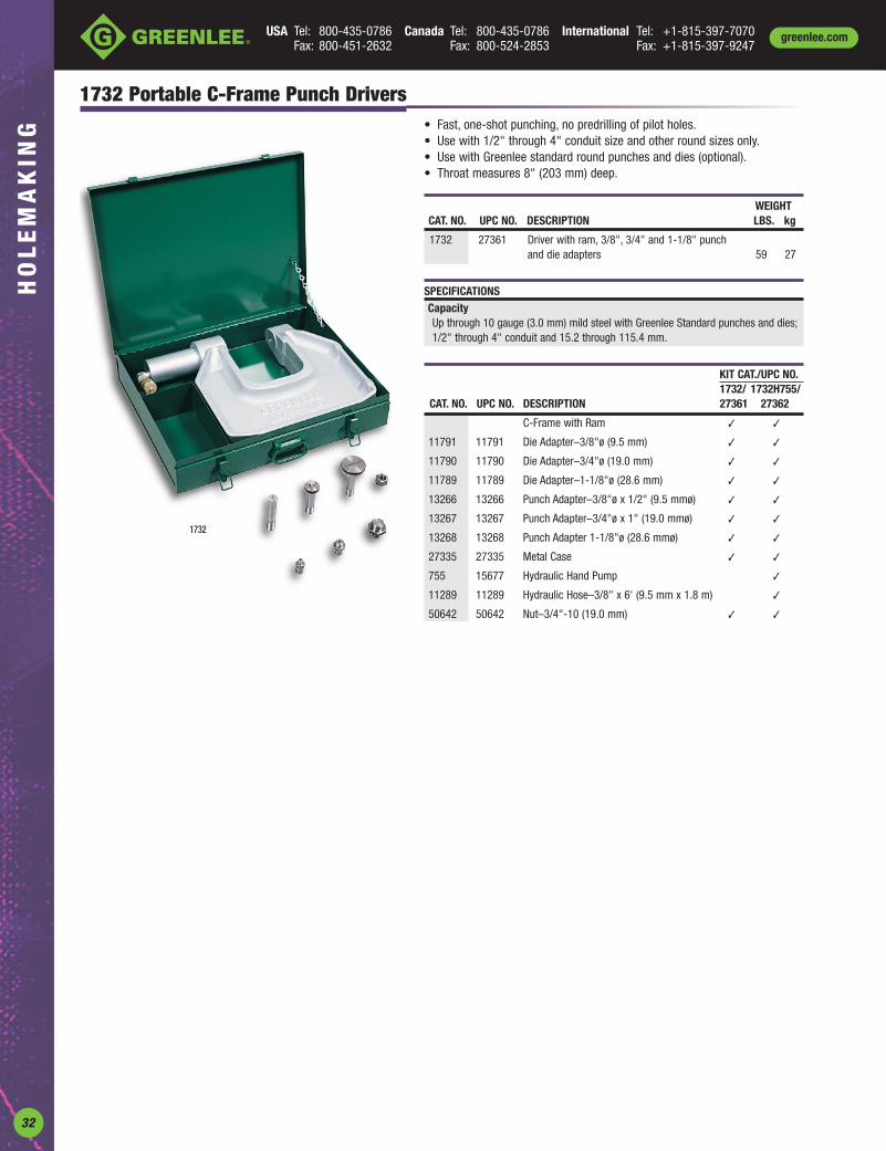
USA Tel: 800-435-0786 Canada Tel: 800-435-0786 International Tel: +1-815-397-7070Fax: 800-451-2632 Fax: 800-524-2853 Fax: +1-815-397-9247
greenlee.comH
OL
EM
AK
ING
32
1732 Portable C-Frame Punch Drivers• Fast, one-shot punching, no predrilling of pilot holes.• Use with 1/2" through 4" conduit size and other round sizes only.• Use with Greenlee standard round punches and dies (optional).• Throat measures 8" (203 mm) deep.
1732
WEIGHTCAT. NO. UPC NO. DESCRIPTION LBS. kg
1732 27361 Driver with ram, 3/8", 3/4" and 1-1/8" punch and die adapters 59 27
SPECIFICATIONSCapacityUp through 10 gauge (3.0 mm) mild steel with Greenlee Standard punches and dies;1/2" through 4" conduit and 15.2 through 115.4 mm.
KIT CAT./UPC NO.1732/ 1732H755/
CAT. NO. UPC NO. DESCRIPTION 27361 27362
C-Frame with Ram ✓ ✓
11791 11791 Die Adapter–3/8"ø (9.5 mm) ✓ ✓
11790 11790 Die Adapter–3/4"ø (19.0 mm) ✓ ✓
11789 11789 Die Adapter–1-1/8"ø (28.6 mm) ✓ ✓
13266 13266 Punch Adapter–3/8"ø x 1/2" (9.5 mmø) ✓ ✓
13267 13267 Punch Adapter–3/4"ø x 1" (19.0 mmø) ✓ ✓
13268 13268 Punch Adapter 1-1/8"ø (28.6 mmø) ✓ ✓
27335 27335 Metal Case ✓ ✓
755 15677 Hydraulic Hand Pump ✓
11289 11289 Hydraulic Hose–3/8" x 6' (9.5 mm x 1.8 m) ✓
50642 50642 Nut–3/4"-10 (19.0 mm) ✓ ✓

USA Tel: 800-435-0786 Canada Tel: 800-435-0786 International Tel: +1-815-397-7070Fax: 800-451-2632 Fax: 800-524-2853 Fax: +1-815-397-9247
HO
LE
MA
KIN
Ggreenlee.com
33
greenlee.com
A
B
C
MAXIMUM CAT./UPC NO. OPTIONALHOLE SIZE CAPACITY PUNCH UNIT BB MINIMUM ADAPTER FOR
INCH mm MILD STEEL OPERATION (INCLUDES PUNCH DRAW DRIVE COUNTER PILOT HOLE Ø WEIGHT HYDRAULICA B C A B C GA mm TYPE DIE AND DRAW STUD) PUNCH DIE STUD NUT NUT INCH mm LBS. kg. DRIVERS
.875 .125 1.000 22.5 3.2 25.4 14 2.0 Hand/Hydr. 60238 60239 60250 60117 60165 60258 .625 15.9 2.1 .95 60167◊1.210 .190 1.380 30.5 4.8 36.0 10 3.5 Hand/Hydr. 60242 60243 60249 60117 60165 60258 .625 15.9 2.7 1.2 60167◊
For maximum draw stud life, Greenlee recommends the use of battery or hydraulic drivers.
CounterNut
Punch Die Draw Stud Ball BearingDrive Nut
Oiltight Punches with NotchesOther oiltight sizes without notches available in standard, Slug-Buster® and Slug Splitter® designs.
Key Punches
A
B
C
CounterNut
Punch Die Ball BearingDrive Nut
Draw Stud
CAT./UPC NO.MAXIMUM PUNCH UNIT OPTIONAL
HOLE SIZE CAPACITY (INCLUDES BB MINIMUM ADAPTER FORINCH mm MILD STEEL OPERATION PUNCH DIE DRAW DRIVE COUNTER PILOT HOLE Ø WEIGHT HYDRAULIC
A B C A B C GA mm TYPE AND DRAW STUD) PUNCH DIE STUD NUT NUT INCH mm LBS. kg. DRIVERS
0.481 Ø 0.055 .030 12.2 Ø 1.4 .8 16 1.5 Hand/Hydr. 60101 60102 60103 60115 60120 05244 .375 9.5 .88 .4 60114◊1.171 Ø 0.123 .097 29.7 Ø 3.1 2.5 14 2.0 Hand/Hydr. 60104 60105 60106 60166 60165 60258 .875 23.8 2.3 1.0 60167◊1.265 Ø 0.156 .097 32.1 Ø 4.0 2.5 14 2.0 Hand/Hydr. 60107 60108 60109 60166 60165 60258 .875 23.8 2.4 1.1 60167◊1.328 Ø 0.102 .097 33.7 Ø 2.6 2.5 14 2.0 Hand/Hydr. 60110 60111 60112 60166 60165 60258 .875 23.8 2.4 1.1 60167◊
◊ For use with any Greenlee Hydraulic Driver or Battery-Powered Driver For maximum draw stud life, Greenlee recommends the use of battery or hydraulic drivers
1/8" Deep
Die
Cutting Notch1/8" Key
Cutting Notch3/16" Key
Punch
3/32" Deep
1. Locate proper cutting notch on the cutting head.
2. Place cutting notch inside edge of hole andcut keyway.
3. Withdraw the punch. 4. Use as a nibbler to make wider or deeper keyways.
720 Keyway Punch• Eliminates time consuming hand sawing and filing when making keyways
for push button switches.• Use as a nibbler to make wider or deeper keyways.• Punches 1/8" (3.2 mm) or 3/16" (4.8 mm) keyways for 7/8" (22.5 mm) or
1-7/32" (30.5 mm) push button holes.• Patented – U.S. Patent No. 4,375,128; Canadian Patent No. 1,172,435.
WEIGHTCAT. NO. UPC NO. DESCRIPTION LBS. kg.
720 26534 Keyway Punch 2.8 1.27
SPECIFICATIONS
Operation ManualCapacity 10 gauge (3.5 mm) mild steel.
3/16"(4.7mm)
1/8"(3.2mm)
720
3/16"
1/8"

USA Tel: 800-435-0786 Canada Tel: 800-435-0786 International Tel: +1-815-397-7070Fax: 800-451-2632 Fax: 800-524-2853 Fax: +1-815-397-9247
greenlee.comH
OL
EM
AK
ING
USA Tel: 800-435-0786 Canada Tel: 800-435-0786 International Tel: +1-815-397-7070Fax: 800-451-2632 Fax: 800-524-2853 Fax: +1-815-397-9247
greenlee.comH
OL
EM
AK
ING
B
A
CounterNut
Punch Die
CAT./UPC NO.MAXIMUM PUNCH UNIT OPTIONAL
HOLE SIZE CAPACITY (INCLUDES BB MINIMUM ADAPTER FORINCH mm MILD STEEL OPERATION PUNCH, DIE DRAW DRIVE COUNTER PILOT HOLE Ø WEIGHT HYDRAULIC
A B A B GA mm TYPE AND DRAW STUD) PUNCH DIE STUD NUT NUT INCH mm LBS. kg. DRIVERS
0.500 Ø 0.469 12.7 Ø 11.9 16 2.0 Hand/Hydr. 60077 60078 60079 60115 60120 05244 .375 9.5 .9 .41 60114◊0.625 Ø 0.594 15.9 Ø 15.1 14 2.0 Hand/Hydr. 60080 60081 60082 60113 34733 04638 .500 12.7 1.1 .50 33967◊0.750 Ø 0.703 19.1 Ø 17.9 14 2.0 Hand/Hydr. 60083 60084 60085 60113 34733 04638 .500 12.7 1.2 .50 33967◊
◊ For use with any Greenlee Hydraulic Driver or Battery-Powered Driver For maximum draw stud life, Greenlee recommends the use of battery or hydraulic drivers
Draw Stud Ball Bearing DriveNut
“D” Punches
Double “D” Punches
A
B
Draw Stud
CAT./UPC NO.MAXIMUM PUNCH UNIT OPTIONAL
HOLE SIZE CAPACITY (INCLUDES BB MINIMUM ADAPTER FORINCH mm MILD STEEL OPERATION PUNCH, DIE AND DRAW DRIVE COUNTER PILOT HOLE Ø WEIGHT HYDRAULIC
A B A B GA mm TYPE DRAW STUD) PUNCH DIE STUD NUT NUT INCH mm LBS. kg. DRIVERS
0.769 Ø 0.642 19.5 Ø 16.3 14 2.0 Hand/Hydr. 60086 60087 60088 60113 34733 04638 .500 12.7 1.1 .50 33967◊0.795 Ø 0.697 20.2 Ø 17.6 14 2.0 Hand/Hydr. 60089 60090 60091 60113 34733 04638 .500 12.7 1.1 .50 33967◊0.913 Ø 0.756 23.2 Ø 19.2 14 2.0 Hand/Hydr. 60092 60093 60094 60113 34733 04638 .500 12.7 1.2 .54 33967◊0.913 Ø 0.795 23.2 Ø 20.2 14 2.0 Hand/Hydr. 60095 60096 60097 60113 34733 04638 .500 12.7 2 .9 33967◊1.375 Ø 1.125 34.9 Ø 28.6 14 2.0 Hand/Hydr. 60098 60099 60100 60166 60165 60258 .875 23.8 2.5 1.1 60167◊
◊ For use with any Greenlee Hydraulic Driver or Battery-Powered Driver For maximum draw stud life, Greenlee recommends the use of battery or hydraulic drivers
CounterNut
Punch Die Ball BearingDrive Nut
A
BSquareSpecial Square Counter
NutPunch Die Draw Stud
CAT./UPC NO.MAXIMUM PUNCH UNIT OPTIONAL
HOLE SIZE CAPACITY (INCLUDES BB MINIMUM ADAPTER FORMILD STEEL OPERATION PUNCH, DIE DRAW DRIVE COUNTER PILOT HOLE Ø WEIGHT HYDRAULIC
INCH mm GA mm TYPE AND DRAW STUD) PUNCH DIE STUD NUT NUT INCH mm LBS. kg DRIVERS
1/2" 0.500 x 0.500 12.7 x 12.7 16 1.5 ◊Hand/Hydr. 60001 60002 60003 60115 60120 05244 .375 9.5 1.1 .50 60114◊5/8" 0.625 x 0.625 15.9 x 15.9 14 2.0 ◊Hand/Hydr. 60004 60005 60006 60116 34733 04638 .500 12.7 1.5 .68 33967◊3/4" 0.750 x 0.750 19.1 x 19.1 14 2.0 ◊Hand/Hydr. 60007 60008 60009 60116 34733 04638 .500 12.7 1.5 .68 33967◊7/8" 0.882 x 0.882 22.4 x 22.4 14 2.0 ◊Hand/Hydr. 60259 60011 60012 60116 34733 04638 .500 12.7 1.8 .82 33967◊
0.945 x 0.945 24.0 x 24.0 14 2.0 ◊Hand/Hydr. 60013 60014 60015 60116 34733 04638 .500 12.7 2.3 1.0 33967◊1" 1.000 x 1.000 25.4 x 25.4 14 2.0 ◊Hand/Hydr. 60016 60017 60018 60117 60165 60258 .625 15.9 2.4 1.1 60167◊
1.772 x 1.772 45.0 x 45.0 10 3.5 ◊Hydr. Only 60287 60288 60289 60118 — 60235 1.188 30.2 6.0 2.7 ◊1-13/16" 1.811 x 1.811 46.0 x 46.0 10 3.5 ◊Hydr. Only 60019 60020 60021 60118 — 60235 1.188 30.2 6.2 2.8 ◊
2" 2.000 x 2.000 50.8 x 50.8 10 3.5 ◊Hydr. Only 60168 60169 60170 60118 — 60235 1.188 30.2 6.9 3.1 ◊2-11/16" 2.677 x 2.677 68.0 x 68.0 10 3.5 ◊Hydr. Only 60171 60172 60173 60118 — 60235 1.188 30.2 10.1 4.6 ◊3-5/8" 3.622 x 3.622 92.0 x 92.0 10 3.5 *Hydr. Only 60174 60175 60176 60118 — 60235 1.188 30.2 14.8 6.7 *
4-1/8" 4.125 x 4.125 104.8 x 104.8 10 3.5 *Hydr. Only 60177 60178 60179 60118 — 60235 1.188 30.2 18.8 8.5 *
5.433 x 5.433 138.0 x 138.0 14 2.0 *Hydr. Only 60234 60023 60024 60118 — 60235 1.188 30.2 20 9.1 *
SPECIAL SQUARE
0.886(A) 0.791(B) 22.5 Ø(A) 20.1(B) 14 2.0 Hand/Hydr. 60125 60126 60127 60116 34733 04638 .500 12.7 .7 .3 33967*For use with with Hand and Foot Pump Hydraulic Drivers with Ram For maximum draw stud life, Greenlee recommends the use of battery or hydraulic drivers◊ For use with any Greenlee Hydraulic Driver, or Battery-Powered Driver
Ball BearingDrive Nut
Square and Special Square Punches
34

USA Tel: 800-435-0786 Canada Tel: 800-435-0786 International Tel: +1-815-397-7070Fax: 800-451-2632 Fax: 800-524-2853 Fax: +1-815-397-9247
HO
LE
MA
KIN
Ggreenlee.com
35
greenlee.com
Rectangular Punches
CAT./UPC NO.MAXIMUM PUNCH UNIT OPTIONAL
HOLE SIZE CAPACITY (INCLUDES BB MINIMUM ADAPTER FORMILD STEEL OPERATION PUNCH, DIE AND DRAW DRIVE COUNTER PILOT HOLE Ø WEIGHT HYDRAULIC
INCH mm GA mm TYPE DRAW STUD) PUNCH DIE STUD NUT NUT INCH mm LBS. kg DRIVERS
0.437 x 0.875 11.1 x 22.2 16 1.5 ◊Hand/Hydr. 60025 60026 60027 60115 60120 05244 .375 9.5 1.2 .5 60114◊0.670 x 0.749 17.0 x 19.0 14 2.0 ◊Hand/Hydr. 60028 60029 60030 60116 34733 04638 .500 12.7 1.5 .68 33967◊0.750 x 1.140 19.1 x 29.0 14 2.0 ◊Hand/Hydr. 60031 60032 60033 60117 60165 60258 .625 15.9 2.3 1.0 60167◊0.750 x 1.310 19.1 x 33.3 14 2.0 ◊Hand/Hydr. 60034 60035 60036 60117 60165 60258 .625 15.9 2.3 1.0 60167◊0.861 x 1.018 21.9 x 25.9 14 2.0 ◊Hand/Hydr. 60037 60038 60039 60117 60165 60258 .625 15.9 2.3 1.0 60167◊0.866 x 1.181 22.0 x 30.0 14 2.0 ◊Hand/Hydr. 60040 60041 60042 60117 60165 60258 .625 15.9 2.4 1.1 60167◊0.866 x 1.654 22.0 x 42.0 14 2.0 ◊Hand/Hydr. 60043 60045 60046 60117 60165 60258 .625 15.9 2.9 1.3 60167◊0.990 x 1.140 25.1 x 29.0 14 2.0 ◊Hand/Hydr. 60047 60048 60049 60117 60165 60258 .625 15.9 2.6 1.2 60167◊1.250 x 1.380 31.8 x 35.1 14 2.0 ◊Hand/Hydr. 60050 60051 60052 60117 60165 60258 .625 15.9 3.1 1.4 60167◊1.312 x 2.625 33.3 x 66.7 10 3.5 ◊Hydr. Only 60053 60054 60055 60118 — 60235 1.188 30.2 5.1 2.3 ◊1.378 x 2.047 35.0 x 52.0 10 3.5 ◊Hydr. Only 60056 60057 60058 60118 — 60235 1.188 30.2 6.1 2.8 ◊1.378 x 2.559 35.0 x 65.0 10 3.5 ◊Hydr. Only 60059 60060 60061 60118 — 60235 1.188 30.2 6.8 3.1 ◊1.378 x 3.228 35.0 x 82.0 14 2.0 *Hydr. Only 60062 60063 60064 60118 — 60235 1.188 30.2 7.7 3.5 *
1.378 x 4.409 35.0 x 112.0 14 2.0 *Hydr. Only 60065 60066 60067 60118 — 60235 1.188 30.2 9.2 4.2 *
1.811 x 3.622 46.0 x 92.0 10 3.5 *Hydr. Only 60068 60069 60070 60118 — 60235 1.188 30.2 8.9 4.0 *
2.250 x 3.500 57.2 x 88.9 10 3.5 *Hydr. Only 60071 60072 60073 60118 — 60235 1.188 30.2 10.1 4.6 *
2.677 x 5.433 68.0 x 138.0 14 2.0 *Hydr. Only 60074 60075 60076 60118 — 60235 1.188 30.2 16.1 7.3 *
*For use with with Hand and Foot Pump Hydraulic Drivers with Ram For maximum draw stud life, Greenlee recommends the use of battery or hydraulic drivers◊ For use with any Greenlee Hydraulic Driver or Battery-Powered Driver
CounterNut
Punch Die Draw Stud Ball BearingDrive Nut
9 PIN229
15 PIN230
25 PINRS232
37 PIN234
50 PIN238
A1.6 mm(1/16")
R.
B
C
10°
SPECIFICATIONS
Operation Manual with a wrench; Quick Draw® and Quick Draw 90® hydraulicdrivers, Battery Driver, Ram and Pump hydraulic drivers.
Capacity 16 gauge (1.5 mm) mild steel; 10 gauge (3.5 mm) aluminum.
PUNCH UNIT DIMENSIONS REPLACEMENT CAT./UPC NO. WEIGHTNO. OF SQUARE
CAT. NO. UPC NO. PINS A B C PUNCH DIE UNIT DRAW STUD COUNTER NUT DRIVE NUT LBS. kg.
229 34436 9 .787" .982" .469" 34441 35196 34421 04638 34733 1.4 .64(20.0 mm) (24.9 mm) (11.9 mm)
231 34437 15 1.127" 1.309" .469" 34442 35197 34421 04638 34733 1.5 .68(28.6 mm) (33.3 mm) (11.9 mm)
RS232 34420 25 1.655" 1.853" .469" 34418 35198 34421 04638 34733 2.0 .91(42.0 mm) (47.1 mm) (11.9 mm)
234 34429 37 2.296" 2.497" .469" 34427 35199 34421 04638 34733 2.0 .91(58.3 mm) (63.4 mm) (11.9 mm)
238 34444 50 2.201" 2.402" .579" 34443 35200 34421 04638 34733 2.0 .91(55.9 mm) (61.0 mm) (14.7 mm)
For maximum draw stud life, Greenlee recommends the use of battery or hydraulic drivers
Electronic Connector Panel Punches• Cut-out and mounting slots are punched in one operation.• Drill only one 7/16" (11.1 mm) pilot hole.
(See catalog page 63 for Kwik Stepper® step bits.)• Fast, accurate panel punching with no sawing or filing required.• Universal size punches for front or back mount of TRW Cinch and
ITT Cannon-type or equivalent connectors in 9, 15, 25, 37 or 50-pinconfigurations.
• U.S. Patent No. 4,899,447.

USA Tel: 800-435-0786 Canada Tel: 800-435-0786 International Tel: +1-815-397-7070Fax: 800-451-2632 Fax: 800-524-2853 Fax: +1-815-397-9247
greenlee.comH
OL
EM
AK
ING
36
Replacement Draw Studs for Manual DriversReplacement Draw Stud Selection GuideIf you need to replace a broken draw stud, refer to the full scale pictures and informationbelow when ordering a replacement draw stud. Sizes given diameter x length.
304AVBB / 04042 – 3/4" (19.0 mm) x 2-15/16" (75 mm)
00042 – 3/8" (9.5 mm) x 1-5/8" (41 mm)
249AVBB / 04040 – 3/4" (19.0 mm) x 2-1/8" (54 mm)
3026AV / 04679 – 1-1/8" (28.6 mm) x 7-1/2" (190 mm)
1434AV / 04188 – 3/4" (19.0 mm) x 5-1/2" (140 mm)
1675AV Draw Stud / 04218 – 1/4" (6.4 mm) x 1-3/8" (35 mm)

USA Tel: 800-435-0786 Canada Tel: 800-435-0786 International Tel: +1-815-397-7070Fax: 800-451-2632 Fax: 800-524-2853 Fax: +1-815-397-9247
HO
LE
MA
KIN
Ggreenlee.com
37
greenlee.com
Replacement Draw Studs for Hydraulic DriversReplacement Draw Stud Selection GuideIf you need to replace a broken draw stud, refer to the full scale pictures and information below when ordering a replacement draw stud.Sizes given diameter x length.
29452 – 3/4" (19.0 mm) x 5-1/2" (140 mm)
1557AA / 03170 – 1-1/8" (28.6 mm) x 3" (76 mm)
2113AA / 03294 – 3/4" (19.0 mm) x 5-3/8" (137 mm)
29451 – 7/16" (11.1 mm) x 4-1/4" (108 mm)
1614SS / 30043 – 3/8" (9.5 mm) x 2-13/16" (71 mm)
Replacement Draw Studs for Ratchet Drivers
12099 – 3/4" (19.0 mm) x 4-3/4" (121 mm)
12097 – 3/8" (9.5 mm) x 3-1/2" (89 mm)
33967 (Adapter) – 3/4" (19 mm) x 1-7/8" (48 mm)
30227 – 7/16" (11.1 mm) x 3-5/8" (92 mm)

USA Tel: 800-435-0786 Canada Tel: 800-435-0786 International Tel: +1-815-397-7070Fax: 800-451-2632 Fax: 800-524-2853 Fax: +1-815-397-9247
greenlee.comH
OL
EM
AK
ING
38
60166 – 1/2" (12.7 mm) x 4-5/8" (117.5 mm)
60117 – 1/2" (12.7 mm) x 4-5/8" (117.5 mm)
60113 – 3/8" (9.5 mm) x 3-11/16" (93.7 mm)
60116 – 3/8" (9.5 mm) x 3-3/4" (95.3 mm)
34421 – 3/8" (9.5 mm) x 3-1/2" (88.9 mm)
60115 – 1/4" (6.3 mm) x 3-7/16" (87.3 mm)
60118 – 3/4" (19 mm)x 6-3/4" (171.5 mm)
Replacement Draw Studs for Special Shape PunchesReplacement Draw Stud Selection GuideIf you need to replace a broken draw stud, refer to the full scale pictures and information below when ordering a replacement draw stud.Sizes given diameter x length.
For maximum draw stud life, Greenlee recommends the use of battery or hydraulic drivers.

USA Tel: 800-435-0786 Canada Tel: 800-435-0786 International Tel: +1-815-397-7070Fax: 800-451-2632 Fax: 800-524-2853 Fax: +1-815-397-9247
HO
LE
MA
KIN
Ggreenlee.com
39
BATTERY-POWERED STUD PUNCH
ACTUAL HOLE SIZE WEIGHT LENGTH HEIGHT CAPACITY
CAT. NO. UPC NO. IN. mm LBS. kg IN. mm IN. mm GA mm BATTERY CHARGER
ESP710-11 10307 1-11/32 34.1 9.2 4.2 15 381 11-3/4 298 16 1.5 12V2.0 Ah NiCd 120 Volt
ESP710-12 10308 1-11/32 34.1 9.2 4.2 15 381 11-3/4 298 16 1.5 12V2.0 Ah NiCd 12 Volt
ESP710-22 10309 1-11/32 34.1 9.2 4.2 15 381 11-3/4 298 16 1.5 12V2.0 Ah NiCd 230 Volt
PLUMBER STUD PUNCH
ACTUAL HOLE SIZE WEIGHT LENGTH HEIGHT CAPACITY
CAT. NO. UPC NO. IN. mm LBS. kg IN. mm IN. mm GA mm
713 06430 2-5/8 66.7 10.6 4.8 23-1/2 596 9-3/4 247 24-20 0.9
Structural Stud Punch• Punch 16 and 18 gauge structural studs in 5 seconds.• Punch 200 holes per battery charge, 2 batteries included eliminating
downtime• Punches a 1.34 (34.1 mm) diameter hole in 16 (1.5 mm) guage steel. For
use with Greenlee 712A bushings.• Swivel head rotates 360° for use in tight corners.• Pistol grip handle gives better leverage and reduces fatigue.• Replacement punch and die.• Lightweight 9.2 lb. tool provides heavy-duty performance.
Plumber Stud Punch• Punches 2-5/8" (66.7 mm) diameter hole in metal studs for professional
looking installation of 2" water, vent, waste pipes.• Two-speed lever action for fast, easy punching of 24 to 20 gauge thick
metal studs.• 2-1/8" (54 mm) throat width fits over most studs and channels.• High strength alloy aluminum c-frame and handle provides lightweight
tool for easy handling–10.6 lb. (4.8 kg).• Lever action punch retraction strips punch out of metal stud fast and
easy.

USA Tel: 800-435-0786 Canada Tel: 800-435-0786 International Tel: +1-815-397-7070Fax: 800-451-2632 Fax: 800-524-2853 Fax: +1-815-397-9247
greenlee.comH
OL
EM
AK
ING
40
Bushings for Metal Stud Punches• Triple lock design holds bushing securely.• Locks securely into metal studs from 24 gauge to 12 gauge (0.6 mm
to 2.5 mm).• Helps protect wire insulation from sharp edges of metal studs.• Makes pulling smooth and easy by preventing hang-ups of cable on
raw metal edges.
R
®
WEIGHTCAT. NO. UPC NO. DESCRIPTION LBS. kg
711C 22288 100 Bushings for hole punched by 709 for 7/8" (22.2 mm) diameter hole .5 .23
711M 22289 1,000 Bushings for hole punched by 709 for 7/8" (22.2 mm) diameter hole 3.7 1.7
712A100 05927 100 Bushings for pre-punched hole or 1-11/32"(34.1 mm) diameter hole punched by 710 1.4 .64
712A1000 05928 1,000 Bushings for pre-punched hole or 1-11/32"(34.1 mm) diameter hole punched by 710 15.5 7.0
MANUAL STUD PUNCH
ACTUAL HOLE SIZE WEIGHT LENGTH HEIGHT CAPACITY
CAT. NO. UPC NO. IN. mm LBS. kg IN. mm IN. mm GA mm
724 10415 1-1/4 31.7 4.0 1.8 16-3/4 426 4-1/2 114 24-20 0.9
WEIGHTCAT. NO. UPC NO. DESCRIPTION LBS. kg
709 22280 7/8" (22.2 mm) Diameter Stud Punch 7 3.2
710 21285 1-11/32" (34.1 mm) Diameter Stud Punch 7.5 3.5
30968 30968 Conversion Kit – Upgrades early model 709 or710 from 24 to 20 gauge maximum capacity
121AV 04006 Punch for 709 – Accessory
22286 22286 Die for 709 – Accessory
24823 24823 Punch for 710 – Accessory
21297 21297 Die for 710 – Accessory
SPECIFICATIONS
Capacity 709 – 1-5/8" (41.3 mm) and wider studs.20 gauge (0.9 mm) steel studs.710 – 2-1/2" (63.4 mm) and wider studs.20 gauge (0.9 mm) steel studs.
Metal Stud Punches• Punch up through 20 gauge (0.9 mm) steel studs in one stroke.• Aluminum head provides strength with minimum weight, reducing
operator fatigue.• Contoured handle design gives better operator leverage and makes it
possible to punch in tight places.• Self-stripping design eliminates punch hang-ups.• Automatically centers holes on standard studs.• Conversion kit available to upgrade early models from 24 gauge to 20
gauge maximum capacity.
Manual Stud Punches• Punch up through 20 gauge (0.9 mm) steel studs in one stroke.• Unique patented punch rolls the edge over for smooth installation of
armored cable; cable won’t hang up.• Contoured handle design gives better operator leverage and makes it
possible to punch in tight places.• Automatically centers holes on standard studs.• Conversion kit available to upgrade early models from 24 gauge to 20
gauge maximum capacity.• 724BX, armored cable stud punch, primary use is the steel studs within
the perimeter of the building.

USA Tel: 800-435-0786 Canada Tel: 800-435-0786 International Tel: +1-815-397-7070Fax: 800-451-2632 Fax: 800-524-2853 Fax: +1-815-397-9247
HO
LE
MA
KIN
Ggreenlee.com
41
greenlee.com
METRIC
SIZE CAT./UPC NO.INCHES mm 34410 34401 36402 30005 34411 34403 30008 36414 36018 36020 360221/8 3.2 ✓
5/32" 4.0 ✓
3/16" 4.8 ✓ ✓ ✓ ✓
7/32" 5.6 ✓
1/4" 6.4 ✓ ✓ ✓ ✓
9/32" 7.1 ✓
5/16" 7.9 ✓ ✓ ✓ ✓
11/32" 8.7 ✓
3/8" 9.5 ✓ ✓ ✓ ✓
0.382" 9.7 ✓
13/32" 10.3 ✓
7/16" 11.1 ✓ ✓ ✓ ✓
15/32" 11.9 ✓
0.492" 12.5 ✓ Pg-71/2" 12.7 ✓ ✓ ✓ ✓ ✓ ✓
9/16" 14.3 ✓ ✓
0.598" 15.2 ✓ Pg-95/8" 15.9 ✓ ✓
0.638" 16.2 ✓ ISO-1611/16" 17.5 ✓ ✓
0.732" 18.6 ✓ Pg-113/4" 19.1 ✓ ✓
0.803" 20.4 ✓ Pg-13 ✓ ISO-2013/16" 20.6 ✓ ✓
7/8" 22.2 ✓ ✓ ✓ ✓
0.886" 22.5 ✓ Pg-161.00" 25.4 ✓ ISO-251.114" 28.3 ✓ Pg-211-1/8" 28.6 ✓ ✓
1.201" 30.5 ✓
1-7/32" 31.0 ✓
1-1/4" 31.8 ✓
1.280" 32.5 ✓ISO-321-3/8" 34.9 ✓
Overall Length 1-5/8" 3-1/8" 3-3/16" 3-3/16" 2-3/16" 3-5/16" 2-1/4" 2-7/8" 1.590" 3-1/2" 3.100"(41.4 mm) (79.4 mm) (81.0 mm) (81.0 mm) (55.6 mm) (84.1 mm) (57.2 mm) (73.0 mm) (40.4 mm) (88.9 mm) (78.7 mm)
Minimum 1/4" 1/4" 1/4" 1/4" 3/8" 3/8" 3/8" 3/8" 1/4" 3/8" 3/8"Chuck Size (6.4 mm) (6.4 mm) (6.4 mm) (6.4 mm) (9.5 mm) (9.5 mm) (9.5 mm) (9.5 mm) (6.4 mm) (9.5 mm) (9.5 mm)Maximum Material 10 gauge 10 gauge 3/8" 10 gauge 10 gauge 10 gauge 10 gauge 10 gauge 10 gauge 1/4" 1/4"Thickness (3.5 mm) (3.5 mm) (9.5 mm) (3.5 mm) (3.5 mm) (3.5 mm) (3.5 mm) (3.5 mm) (3.5 mm) (6.4 mm) (6.4 mm)Bit Extension 901 901 901 901 — — — — 901 — —
1/2" 1/2" 1/2" 13/16" 7/8" 7/8" 1-1/8" 1-3/8" 9.7 mm 30.5 mm 32.5 mm(12.7 mm) (12.7 mm) (12.7 mm) (20.6 mm) (22.2 mm) (22.2 mm) Electrician’s (34.9 mm) (.382") (1.201") (1.280")
Single-Hole Multi-Hole Multi-Hole Multi-Hole Single-Hole Multi-Hole Step Bit Single-Hole Multi-Hole Multi-HoleStep Bit Step Bit Step Bit Step Bit Step Bit Step Bit Step Bit Step Bit Step Bit
Single-hole bits aredesigned to drill oneindicated hole sizethrough a series of stepsfrom bit tip to full size.
Multi-hole bits allow youto drill a hole in any ofthe stated diameters.
Kwik Stepper Step Bits• Unique split tip design penetrates through steel faster.• Resists walking or skidding, even on round surfaces.• Balanced, double-flute construction requires less pressure,
does the work for you.• Designed and manufactured in USA.
SPECIFICATIONSHole Sizes From 1/8" through 1-3/8" (3.2 - 34.9 mm)
Capacity Cut up through 3/8" (9.5 mm) mild steel, copper, brass,aluminum, wood, plastic and laminates.
CAT. NO. UPC NO. DESCRIPTION35884 35884 Kwik Stepper® Step Bit Kit03607 03607 Kwik Stepper® Step Bit Kit
CAT. NO. UPC NO. DESCRIPTION 03607 3588434401 34401 1/2" Multi-Hole Step Bit • •34403 34403 7/8" Multi-Hole Step Bit • •30008 30008 1-1/8" Multi-Hole Step Bit •35936 35936 Plastic Case • •
03607
35884

USA Tel: 800-435-0786 Canada Tel: 800-435-0786 International Tel: +1-815-397-7070Fax: 800-451-2632 Fax: 800-524-2853 Fax: +1-815-397-9247
greenlee.comH
OL
EM
AK
ING
42
• Cuts stainless steel quickly and easily.• Kwik Change™ arbor allows you to
change cutter heads with a simplepush and a turn. Use the samearbor for different sizecutting heads.
• Removable cutterheads available insizes from 5/8" through 3".
• Flange stop prevents over-drilling.• Ejector Spring on all sizes above 3/4" makes removal of slug
easier.• Replaceable, cobalt-steel pilot drill with split-point tip to
prevent walking.• Precision carbide teeth for optimum performance and
durability.• Minimum chuck size of 3/8"
Kwik Change™ Stainless Steel Hole Cutters
INDIVIDUAL CARBIDE-TIPPED HOLE CUTTERSKIT CAT. KIT CAT.
MIN. NO. 660/ NO. 655/SIZE CONDUIT CHUCK SIZE UPC NO. UPC NO.
CAT. NO. UPC NO. INCH mm SIZE PG ISO INCH mm 05766 05820
645–5/8 05691 5/8 15.8 3/8 9.5
645–11/16 05692 11/16 17.5 3/8 9.5
645–3/4 05693 3/4 19.0 11 3/8 9.5
645–13/16 05694 13/16 20.6 13 20 3/8 9.5
645–7/8 05695 7/8 22.2 1/2" 3/8 9.5 ✓ ✓
645–1 05696 1 25.4 25 3/8 9.5
645–1-1/16 05957 1-1/16 27.0 3/8 9.5
645–1-1/8 05697 1-1/8 28.6 3/4" 21 3/8 9.5 ✓ ✓
645–1-7/32 05698 1-7/32 31.0 3/8 9.5
645–1-1/4 05699 1-1/4 31.8 3/8 9.5
645–1-5/16 05958 1-5/16 33.3 32 3/8 9.5
645–1-3/8 05700 1-3/8 34.9 1" 3/8 9.5 ✓ ✓
645–1-7/16 05959 1-7/16 36.5 27 3/8 9.5
645–1-1/2 05701 1-1/2 38.1 3/8 9.5
645–1-3/4 05702 1-3/4 44.4 1-1/4" 3/8 9.5 ✓
645–2 05703 2 50.8 1-1/2" 50 3/8 9.5 ✓
645–2-1/8 05960 2-1/8 54.0 42 3/8 9.5
645–2-1/4 05704 2-1/4 57.2 48 3/8 9.5
645–2-3/8 05961 2-3/8 60.3 3/8 9.5
645–2-1/2 05705 2-1/2 63.5 2" 63 3/8 9.5
645–2-5/8 05706 2-5/8 66.7 3/8 9.5
645–3 05707 3 76.2 3/8 9.5
ARBORS AND PILOT DRILLSKIT CAT. KIT CAT.NO. 660/ NO. 655/UPC NO. UPC NO.
CAT. NO. UPC NO. DESCRIPTION 05766 05820
645–011 05752 Kwik Change™ Arbor for sizes5/8" through 2-1/4"
✓ ✓
645–022 05753 Kwik Change™ Arbor for sizes2-3/8" through 3"
645–001 05761 Pilot Drill for sizes 5/8"through 2-1/4"
✓ ✓
645–002 05762 Pilot Drill for sizes 2-3/8"through 3"
KITSCAT. NO. UPC NO. DESCRIPTION
660 05766 7/8", 1-1/8", 1-3/8", 1-3/4", 2" cutterheads; arbor, hex key and case
655 05820 7/8", 1-1/8", 1-3/8" cutter heads; arbor,hex key and case
660

USA Tel: 800-435-0786 Canada Tel: 800-435-0786 International Tel: +1-815-397-7070Fax: 800-451-2632 Fax: 800-524-2853 Fax: +1-815-397-9247
HO
LE
MA
KIN
Ggreenlee.com
43
KITWEIGHT
CAT. NO. UPC NO. DESCRIPTION LBS. kg
635 03599 7/8", 1-1/8", 1-3/8" cutterheads; pilot drill,hex key and case 1.2 .54
CARBIDE-TIPPED HOLE CUTTERSKIT CAT.
MIN. NO. 635/SIZE CONDUIT CHUCK SIZE WEIGHT UPC NO.
CAT. NO. UPC NO. INCH mm SIZE PG ISO INCH mm LBS. g 03599
625–3/4 38324 3/4 19.0 11 1/4 6.4 .02 9
625–13/16 38325 13/16 20.6 13 20 1/4 6.4 .02 9
625–7/8 38326 7/8 22.2 1/2" 16 1/4 6.4 .33 150 ✓
625–1 38327 1 25.4 25 3/8 9.5 .02 9
625–1-1/8 38328 1-1/8 28.6 3/4" 21 3/8 9.5 .43 195 ✓
625–1-7/32 38329 1-7/32 30.5 3/8 9.5 .44 200
625–1-1/4 38330 1-1/4 31.7 3/8 9.5 .33 150
625–1-3/8 38331 1-3/8 35.0 1" 3/8 9.5 .47 213 ✓
625–1-1/2 38332 1-1/2 38.1 3/8 9.5 .37 168
625–1-3/4 38333 1-3/4 44.4 1-1/4" 3/8 9.5 .40 182
625–2 38334 2 50.8 1-1/2" 50 3/8 9.5 .50 227
625–2-1/2 38336 2-1/2 63.5 2" 1/2 12.7 .67 304
All hole cutters are packaged in Point of Purchase blister pack.
SPECIFICATIONS
Maximum Cutting Depth 8 Ga. (4 mm)
REPLACEMENT PILOT DRILLS
CUTTER SIZE RANGE PILOT DRILL HEX SET SCREW WT.INCH mm CAT. NO. UPC NO. SIZE CAT./UPC NO. LBS. g
3/4-2 19.0-50.8 625–001 39872◊ 3 mm 54274 .19 86
2-1/2 63.5 625–002 38390 4 mm 54295 .28 127
◊ Point of Purchase Package
Carbide-Tipped Hole Cutters• Multiple tungsten carbide tips for long life and smooth cutting.• Cut fast, accurate, high quality holes in stainless steel, copper,
aluminum, steel.• Flange stop prevents over drilling.• Replaceable cobalt steel pilot drill, with split point tip design, to improve
performance and resist walking; eliminates need for “center punch.”

USA Tel: 800-435-0786 Canada Tel: 800-435-0786 International Tel: +1-815-397-7070Fax: 800-451-2632 Fax: 800-524-2853 Fax: +1-815-397-9247
greenlee.comH
OL
EM
AK
ING
44
HIGH-SPEED STEEL CUTTERSACTUAL HOLE SIZE HOLE DIAMETER
CAT. NO. UPC NO. IN. mm CONDUIT PG ISO COPPER PIPE
925-7/8 10157 7/8 22.5 1/2" Pg-16 5/8"
925-1-1/8 10158 1-1/8 28.6 3/4" Pg-21
925-1-7/32 10643 1-7/32 30.5
925-1-3/8 10159 1-3/8 35.0 1"
925-1-3/4 10160 1-3/4 44.4 1-1/4" 1-1/2"
925-2 10161 2 50.8 1-1/2" ISO-50
925-2-1/2 10162 2-1/2 63.5 ISO-63 2"
KITCAT. NO. UPC NO. DESCRIPTION
930 10214 High-Speed Steel Cutter Kit: Includes 7/8" to 2-1/2" cutters, two smallarbors for extended assembly to 7/8" and 1-1/2" cutters, large arbor, hexwrench, case. For conduit sizes 1/2" through 2".
ARBORS AND PILOT DRILLS
CAT. NO. UPC NO. DESCRIPTION
925-011 10163 Small Arbor with pilot drill
925-022 10185 Large Arbor with pilot drill
925-001 10186 Small Pilot Drill
925-002 10211 Large Pilot Drill
RECOMMENDED CUTTING SPEEDS
CUTTER SIZE RPM
7/8" (22.5 mm) 350
1-1/8" (28.6 mm) 270
1-3/8" (35.0 mm) 220
1-3/4" (44.4 mm) 175
2" (50.8 mm) 150
2-1/2 (63.5 mm) 120
AVERAGE AVERAGE AVERAGECUTTING TIME NUMBER COST/HOLE
HOLE SAW TYPE (SEC/HOLE) OF HOLES ($)
Bi-Metal 25 50 0.1
High-Speed Cutter 10 500 0.1
Carbide-Tipped Cutter 10 500 0.2
*For 7/8" Hole in 14ga Mild Steel* Cutters made from high-speed steel. Follow recommended cutting speeds.
High-Speed Steel Cutters*• Lasts 10 times longer than standard hole saws.• Precision-ground teeth cut smooth, burr-free holes with ease.• Durability and speed provide low cost per hole.• Split-point pilot drill prevents “walking” – makes accurate hole
placement easy.• Spring-loaded slug ejector saves time.• No tool required to change cutter sizes.• Less chance of broken teeth because the saw body is machined out of
solid, high-speed steel.

USA Tel: 800-435-0786 Canada Tel: 800-435-0786 International Tel: +1-815-397-7070Fax: 800-451-2632 Fax: 800-524-2853 Fax: +1-815-397-9247
HO
LE
MA
KIN
Ggreenlee.com
45
UPC NO. UPC NO. UPC NO. ACTUAL HOLE SIZE HOLE DIA. COPPER USE WITH WEIGHTCAT. NO. STANDARD PACK BULK PACK POINT OF PURCHASE INCH mm CONDUIT PG ISO PIPE SIZE ARBOR NO. LBS. g
825–9/16 19131 — 9/16 14.3 1/8" .1 46825–5/8 19132 — 5/8 15.9 Pg-9 1/4" .1 46825–11/16 19133 — 11/16 17.5 ISO-16 3/8" .1 46825–3/4 19134 29828 00140 3/4 19.0 Pg-11 1/2" .1 46825–13/16 19135 — 13/16 20.6 Pg-13 ISO-20 1/2" .1 46825–7/8 19136 29829 38495 7/8 22.2 1/2" Pg-16 5/8" .1 46825–15/16 19137 — 15/16 23.8 .1 46825–1 19138 — 1 25.4 ISO-25 3/4" .1 46825–1-1/16 19140 — 1-1/16 27.0 .1 46825–1-1/8 19141 29831 38496 1-1/8 28.6 3/4" Pg-21 3/4" .1 46825–1-3/16 19143 — 1-3/16 30.2 .2 91825–1-1/4 19144 — 1-1/4 31.7 1" .2 91825–1-5/16 19145 — 1-5/16 33.3 ISO-32 .2 91825–1-3/8 19146 29832 38497 1-3/8 35.0 1" .1 46825–1-7/16 19147 — 1-7/16 36.5 Pg-29 .2 91825–1-1/2 19148 — 1-1/2 38.1 1-1/4" .2 91825–1-9/16 19149 — 1-9/16 39.7 .2 91825–1-5/8 19150 — 1-5/8 41.3 ISO-40 .2 91825–1-11/16 19151 — 1-11/16 42.9 .3 137825–1-3/4 19152 29834 38498 1-3/4 44.4 1-1/4" 1-1/2" .2 91825–1-13/16 19153 — 1-13/16 46.0 .2 91825–1-7/8 19154 — 1-7/8 47.6 Pg-36 .3 137825–2 19155 29835 38500 2 50.8 1-1/2" ISO-50 .2 91825–2-1/16 19157 — 2-1/16 52.4 .3 137825–2-1/8 19158 — 2-1/8 54.0 Pg-42 .3 137825–2-1/4 19159 — 2-1/4 57.2 2" .3 137825–2-5/16 19160 — 2-5/16 58.7 .5 227825–2-3/8 19161 — 2-3/8 60.3 Pg-48 2" .3 137825–2-1/2 19162 29836 38502 2-1/2 63.5 2" ISO-63 2" .3 137825–2-9/16 19163 — 2-9/16 65.0 .4 182825-2-5/8 19164 — 2-5/8 66.7 .4 182825–2-3/4 19165 — 2-3/4 69.8 .4 182825–2-7/8 19166 — 2-7/8 73.0 .4 182825–3 19167 29837 00141 3 76.2 2-1/2" 2-1/2" .5 227825–3-1/8 19168 — 3-1/8 79.4 .5 227825–3-1/4 19169 — 3-1/4 82.5 .6 273825–3-3/8 19170 — 3-3/8 85.7 .6 273825–3-1/2 19171 — 3-1/2 88.9 .6 273825–3-5/8 19172 29838 00142 3-5/8 92.1 3" .6 273825–3-3/4 19174 — 3-3/4 95.2 .7 318825–3-7/8 19175 — 3-7/8 98.4 3-1/2" .7 318825–4 19176 — 4 101.6 .7 318825–4-1/8 19177 00143 4-1/8 104.8 3-1/2" 3-1/2" .8 363825–4-1/4 19178 — 4-1/4 108.0 4" .8 363825–4-3/8 19179 — 4-3/8 111.1 .8 363825–4-1/2 19180 00144 4-1/2 114.3 4" .9 409825–4-3/4 19181 — 4-3/4 120.6 1.1 499825–5 19182 — 5 127.0 1.2 545825–5-1/2 19183 — 5-1/2 139.7 5" 1.2 545825–6 19184 — 6 152.4 1.4 636
37157,37155,
or 38522
37156 or37154
37156
37156
Bi-Metal Hole Saws• Cut through steel, tin, aluminum, fiberglass, wood and plastic.• Deep 1-5/8" (41.3 mm) cutting depth allows for cutting through 2" x 4"
wood studs.• Extra-tough M42 alloy blade – we use the highest grade of tool steel to
outlast competitor’s blades. That beats premature saw replacement andsaves you money.
• Steam oxide finish – no paint to gum up and slow cutting. The saw runscooler for longer life and better performance.
• Extra-thick backplate minimizes vibration for smoother, easier, less-tiringcutting.
• Made in USA.

USA Tel: 800-435-0786 Canada Tel: 800-435-0786 International Tel: +1-815-397-7070Fax: 800-451-2632 Fax: 800-524-2853 Fax: +1-815-397-9247
greenlee.comH
OL
EM
AK
ING
46
Arbors With Replacement High Speed Steel Pilot Drill Bits• The best arbor in the industry ensures a solid connection without any gaps or wobbling.• Arbors include replaceable high speed pilot drill.• Pilot drills have unique split point tip design.• Use with Greenlee bimetal hole saws, recessed light hole saws, and carbide grit hole saws (carbide tipped pilot drill sold separately).• Can be used with Greenlee #901, #902 and #904 bit extensions.
ARBORS
Cat./UPC No.Standard Pack 37157 38522 37155 37154 37156Point of Purchase Pack 38507 38524 38505 38504 38506Bulk Pack 37157B 38522B 37155B 37154B 37156B
Shank Round with 3 flats Hex Hex Hex HexShank Size 1/4" (6.4 mm) 5/16" (7.9 mm) 7/16" (11.1 mm) 5/16" (7.9 mm) 7/16" (11.1 mm)Min. Chuck Size 1/4" (6.4 mm) 3/8" (9.5 mm) 1/2" (12.7 mm) 3/8" (9.5 mm) 1/2" (12.7 mm)Use With 9/16" - 1-3/16" 9/16" - 1-3/16" 9/16" - 1-3/16" 1-1/4" - 2" 1-1/4" - 6"
(14.3 - 30.2 mm) (14.3 - 30.2 mm) (14.3 - 30.2 mm) (31.8 - 50.8 mm) (31.8 - 152.4 mm)Hole Saws Hole Saws Hole Saws Hole Saws Hole Saws
and all GreenleeRecessed Light
Hole SawsWeight .2 lbs (91 g) .2 lbs (91 g) .2 lbs (91 g) .5 lbs (227 g) .5 lbs. (227 g)
HIGHSPEEDPILOTDRILLS
Cat./UPC No.
Standard Pack 37623 38526
Point ofPurchase Pack 39873 39893
Bulk PackQty: 50 per pack 37624 38991
Length 4-1/8" 3-1/4"(104.8 mm) (82.5 mm)
Diameter 1/4" 1/4"(6.4 mm) (6.4 mm)
Use With 37157, 37155, 38522, 37155,Greenlee 37156 & 37156 &Arbor #’s 37154 37154
Weight .2 lbs (91 g) .2 lbs (91 g)
CARBIDE GRIT HOLE SAWSACTUAL HOLE SIZE HOLE DIAMETER
CAT. NO. UPC NO. INCH mm CONDUIT PG ISO
725–7/8 10072 7/8 22.2 1/2" 16
725–1-1/8 10073 1-1/8 28.6 3/4" 21
725–1-3/8 10075 1-3/8 35.0 1"
725–1-1/2 10076 1-1/2 38.1
725–1-3/4 10077 1-3/4 44.4 1-1/4"
725–2 10078 2 50.8 1-1/2" 50
725–2-1/8 10079 2-1/8 54.0
725–2-1/2 10080 2-1/2 63.5 2" 63
725–3-5/8 10081 3-5/8 92.1 3"
725–4-1/8 10687 4-1/8 104.8 3-1/2"
725–4-1/2 01879 4-1/2 114.3 4"
PILOT DRILL
CAT. NO. UPC NO. DESCRIPTION
725–001 10082 1/4" Carbide Tipped Pilot Drill
Carbide-Grit Hole Saws• Long-lasting tungsten carbide-grit delivers extremely clean, smooth cuts
through tile, cement board, and other abrasive materials. Perfect forcutting holes in Quazite®* enclosure or hardy board siding for 3-0 boxinstallation.
• Rugged construction for enduring performance.• Use with Arbors listed below.
* Quazite is a registered trademark of Strongwell Corporation.

USA Tel: 800-435-0786 Canada Tel: 800-435-0786 International Tel: +1-815-397-7070Fax: 800-451-2632 Fax: 800-524-2853 Fax: +1-815-397-9247
HO
LE
MA
KIN
Ggreenlee.com
47
Bi-Metal Hole Saw Kits• Several electrician’s kits available providing an assortment of the
most commonly used Greenlee variable pitch hole saw sizes and arbors.• High-impact, rugged plastic carrying case.
830 / 19192
834 / 19913
835 / 27538
890 / 03479 891 / 03480889 / 03478
WEIGHTCAT. NO. UPC NO. DESCRIPTION LBS. kg830 19192 Hole Saw Kit for 1/2" through 2" conduit sizes 2.7 1.2834 19913 Hole Saw Kit for 2-1/2" through 4" conduit sizes 6.2 2.8835 27538 Hole Saw Kit for 1/2" through 4" conduit sizes 7.7 3.5830Pg 29209 Hole Saw Kit for Pg-9 through Pg-48 2.7 1.2889 03478 Plumbers Hole Saw Kit – 3/4" through 2-1/4"
conduit sizes 2.3 1.0890 03479 Industrial Maintenance Hole Saw Kit – 3/4"
through 4-3/4" conduit sizes 9.7 4.4891 03480 Electrician’s/Plumbers Hole Saw Kit - 3/4"
through 2-1/2" conduit sizes 3.5 1.6
KIT CAT./UPC NO.830/ 834/ 835/ 830PG/ 889/ 890/ 891/
CAT. NO. UPC NO. DESCRIPTION 19192 19913 27538 29209 03478 03479 03480
825–3/4 19134 3/4" Hole Saw ✓ ✓ ✓
825–7/8 19136 7/8" Hole Saw ✓ ✓ ✓ ✓ ✓ ✓
825–1 19138 1" Hole Saw ✓
825–1-1/8 19141 1-1/8" Hole Saw ✓ ✓ ✓ ✓ ✓ ✓
825–1-3/8 19146 1-3/8" Hole Saw ✓ ✓ ✓ ✓
825–1-1/2 19148 1-1/2" Hole Saw ✓ ✓ ✓
825–1-3/4 19152 1-3/4" Hole Saw ✓ ✓ ✓ ✓ ✓
825–2 19155 2" Hole Saw ✓ ✓ ✓ ✓
825–2-1/4 19159 2-1/4" Hole Saw ✓ ✓ ✓
825–2-1/2 19162 2-1/2" Hole Saw ✓ ✓ ✓ ✓
825–3 19167 3" Hole Saw ✓ ✓ ✓
825–3-1/4 19169 3-1/4" Hole Saw ✓
825–3-5/8 19172 3-5/8" Hole Saw ✓ ✓ ✓
825–3-3/4 19174 3-3/4" Hole Saw ✓
825–4-1/8 19177 4-1/8" Hole Saw ✓ ✓ ✓
825–4-1/2 19180 4-1/2" Hole Saw ✓ ✓
825–4-3/4 19181 4-3/4" Hole Saw ✓
825–5/8 19132 Pg-9 (15.9 mm) Hole Saw ✓
825–3/4 19134 Pg-11 (19.0 mm) Hole Saw ✓
825–13/16 19135 Pg-13 (20.6 mm) Hole Saw ✓
825–1-3/16 19143 30.2 mm Hole Saw ✓
825–1-1/2 19148 Pg-29 (38.1 mm) Hole Saw ✓
825–1-7/8 19154 Pg-36 (47.6 mm) Hole Saw ✓
825–2-3/8 19161 Pg-48 (60.3 mm) Hole Saw ✓
38522 38522 Arbor w/pilot drill (2)37157 37157 Arbor w/pilot drill ✓
37155 37155 Arbor w/pilot drill ✓ ✓ ✓ ✓ ✓
37156 37156 Arbor w/pilot drill ✓ ✓ ✓ ✓ ✓ ✓ ✓
38526 38526 Pilot Drill ✓ ✓ ✓

USA Tel: 800-435-0786 Canada Tel: 800-435-0786 International Tel: +1-815-397-7070Fax: 800-451-2632 Fax: 800-524-2853 Fax: +1-815-397-9247
greenlee.comH
OL
EM
AK
ING
48
RPMHOLE SAW SIZEINCH mm MILD STEEL CAST IRON BRASS ALUMINUM9/16 14.3 580 400 790 900
5/8 15.9 550 365 730 825
11/16 17.5 500 330 665 750
3/4 19.0 460 300 600 690
13/16 20.6 425 280 560 635
7/8 22.2 390 260 520 585
15/16 23.8 370 245 495 555
1 25.4 350 235 470 525
1-1/16 27.0 325 215 435 480
1-1/8 28.6 300 200 400 450
1-3/16 30.2 285 190 380 425
1-1/4 31.7 275 180 360 410
1-5/16 33.3 260 175 345 390
1-3/8 35.0 250 165 330 375
1-7/16 36.5 240 160 315 360
1-1/2 38.1 230 150 300 345
1-9/16 39.7 220 145 290 330
1-5/8 41.3 210 140 280 315
1-11/16 42.9 205 135 270 305
1-3/4 44.4 195 130 260 295
1-13/16 46.0 190 125 250 285
1-7/8 47.6 180 120 240 270
2 50.8 170 115 230 255
2-1/16 52.4 165 110 220 245
2-1/8 54.0 160 105 210 240
2-1/4 57.2 150 100 200 225
Recommended Hole Saw Cutting Speeds
RPMHOLE SAW SIZEINCH mm MILD STEEL CAST IRON BRASS ALUMINUM
2-5/16 58.7 150 100 195 225
2-3/8 60.3 140 95 190 200
2-1/2 63.5 135 90 180 205
2-9/16 65.0 130 85 175 200
2-5/8 66.7 130 85 170 195
2.677 68.0 125 80 160 185
2-3/4 69.8 125 80 160 185
2-7/8 73.0 120 80 160 180
2.913 74.0 115 75 150 170
3 76.2 115 75 150 170
3-1/8 79.4 110 70 140 165
3-1/4 82.5 105 70 140 155
3-3/8 85.7 100 65 130 150
3-1/2 88.9 95 65 130 145
3-5/8 92.1 95 60 120 140
3-3/4 95.2 90 60 120 135
3-7/8 98.4 90 60 120 135
4 101.6 85 55 110 130
4-1/8 104.8 80 55 110 120
4-1/4 108.0 80 55 110 120
4-3/8 111.1 80 50 100 120
4-1/2 114.3 75 50 100 105
4-3/4 120.6 75 50 95 95
5 127.0 65 45 90 90
5-1/2 139.7 60 35 85 85
6 152.4 55 35 75 75
CAT. NO. UPC NO. DESCRIPTION
1940 34953 Flex Splitter® Flexible Metal Conduit Cutter
1941-1 00288 Single Blade Replacement Blade for 1940
1941-5 33735 5 Pack Replacement Blades for 1940
SPECIFICATIONS
Capacity 14/2 to 10/4 BX 3/8" flexible metal conduit
Weight 1940 – 4 lbs. (1.8 kg)
Flex Splitter® BX and Flexible Conduit Cutter• Cut flexible metal conduit in seconds with a few turns of the crank and
an easy twist of the conduit.• Ample clearance between handle and body for comfortable operation.• Set conduit size for multiple cuts of the same size conduit. No need
to reset.• Compact and lightweight. Fits easily in back pocket or tool pouch.• Set blade adjustment with only a screwdriver.• Convenient in-handle blade storage – holds up to five spare blades.• Point-of-purchase packaged. Blades point-of-purchase packaged 1 and
5 blades per package.

USA Tel: 800-435-0786 Canada Tel: 800-435-0786 International Tel: +1-815-397-7070Fax: 800-451-2632 Fax: 800-524-2853 Fax: +1-815-397-9247
HO
LE
MA
KIN
Ggreenlee.comUSA Tel: 800-435-0786 Canada Tel: 800-435-0786 International Tel: +1-815-397-7070
Fax: 800-451-2632 Fax: 800-524-2853 Fax: +1-815-397-9247H
OL
EM
AK
ING
greenlee.com
Reciprocating Blades• Progressive-pitch reciprocating saw blades cut a wide rage of standard construction materials quickly and cleanly – regardless of thickness.• Bimetal construction provides maximum flexibility and break resistance – plus lasting sharpness.• Exclusive plunge tip makes starting cuts faster and easier.• Blades color coded by application.
16-gauge metal stud
strutEMT conduit thickwall pipe
rod/rebar
RECIPROCATING SAW BLADESLENGTH x WIDTH x THICKNESS TEETH QTY.
CAT. NO. UPC NO. INCHES mm PER INCH TYPE APPLICATION PER PK.353-123 09963 6 x 3/4 x .035 152 x 19.05 x .889 Progressive Bimetal, Metal 5
Straight353-318 09961 4 x 5/16 x .035 101 x 7.938 x .889 18 Bimetal, Metal 5
Scroll353-418 09962 4 x 3/4 x .035 101 x 19.05 x .889 18 Bimetal, Metal 5
Straight353-614 09964 6 x 3/4 x .035 152 x 19.05 x .889 14 Bimetal, Metal 5
Straight353-618 09965 6 x 3/4 x .035 152 x 19.05 x .889 18 Bimetal, Metal 5
Straight353-624 09966 6 x 3/4 x .035 152 x 19.05 x .889 24 Bimetal, Metal 5
Straight353-804 09977 8 x 3/4 x .050 203 x 19.05 x 1.27 10/14 Bimetal, Metal 2
Straight353-814 09975 8 x 3/4 x .050 203 x 19.05 x 1.27 14 Bimetal, Metal 2
Straight353-818 09976 8 x 3/4 x .050 203 x 19.05 x 1.27 18 Bimetal, Metal 2
Straight353-234 09991 8 x 3/4 x .050 203 x 19.05 x 1.27 Progressive HCS, Wood Only 5
Taper353-656 09967 6 x 3/4 x .050 152 x 19.05 x 1.27 6 Bimetal, Wood with Nails 5
Taper353-676 09971 6 x 3/4 x .050 152 x 19.05 x 1.27 6 Bimetal, Wood with Nails 5
Scroll353-646 09968 6 x 3.4 x .050 152 x 19.05 x 1.27 6 Bimetal, Wood with Nails 5
Straight353-956 09969 9 x 3/4 x .050 228 x 19.05 x 1.27 6 Bimetal, Wood with Nails 5
Straight353-156 09970 12 x 3/4 x .050 304 x 19.05 x 1.2 6 Bimetal, Wood with Nails 5
Straight353-666 09978 6 x 7/8 x .062 152 x 22.23 x 1.56 6 Bimetal, Wood Demolition 2
Taper353-966 09979 9 x 7/8 x .062 228 x 22.23 x 1.56 6 Bimetal, Wood Demolition 2
Taper353-669 09980 6 x 7/8 x .062 152 x 22.23 x 1.56 8/10 Bimetal, Metal Demolition 2
Taper353-969 09990 9 x 7/8 x .062 228 x 22.23 x 1.56 8/10 Bimetal, Metal Demolition 2
Taper353-345 09972 8 x 3/4 x .050 203 x 19.05 x 1.27 Progressive Bimetal, General 5
Taper353-636 09973 6 x 3/4 x .050 152 x 19.05 x 1.27 6 Bimetal, Plaster 5
Taper353-800 09974 8 x 3/4 x .050 203 x 19.05 x 1.27 Grit Carbide, Abrasive 2
Straight Materials353-VAR 09992 6 x 3/4 x .035 152 x 19.05 x .889 Progressive 353–123 Metal 1
8 x 3/4 x .050 203 x 19.05 x 1.27 Progressive 353–234 Wood Only 18 x 3/4 x .050 203 x 19.05 x 1.27 Progressive 353–345 General 1
Metal
Wood
Demolition
Specialty
Variety49

USA Tel: 800-435-0786 Canada Tel: 800-435-0786 International Tel: +1-815-397-7070Fax: 800-451-2632 Fax: 800-524-2853 Fax: +1-815-397-9247
greenlee.comH
OL
EM
AK
ING
HO
LE
MA
KIN
G
JIG SAW BLADESCAT. NO. UPC NO. DESCRIPTION TEETH TYPE APPLICATION QTY. PER PK.373-U123 09994 3-5/8" Univeral Jig Saw Blade Progressive High-speed Steel Metal 5373-U234 09993 4-1/4" Universal Jig Saw Blade Progressive High-carbon Steet Wood 3373-U345 09995 5" Universal Jig Saw Blade Progressive Bimetal General 5373-U300 09996 2-3/4" Universal Jig Saw Blade Grit Carbide Grit Abrasive Materials 2373-UVAR 09997 Universal Jig Saw Blade – Progressive 373-U123 Metal, Wood 1
Variety Pack 373-U234 and General373-U345
373-T123 10004 4" T-Shank Jig Saw Blade Progressive High-speed Steel Metal 3373-T234 10003 4-1/2" T-Shank Jig Saw Blade Progressive High-carbon Steel Wood 5373-T345 10005 5-1/4" T-Shank Jig Saw Blade Progressive Bimetal General 5373-TVAR 10006 T-Shank Jig Saw Blade – Progressive 373-T123 Metal, Wood 1
Variety Pack 373-T234 and General373-T345
Jig Saw Blades
• Progressive-tooth design delivers faster cutting through a broad range of material types and thicknesses.
• Shatterproof bi-metal construction with high speed cobalt matrix cutting edge.• For rough and finish cutting in full range of applications including wood (even with nails), metal, plaster, drywall and fiberglass.• Tungsten Carbide Grit Edge blade style.
–No teeth to snag, cuts efficiently on both up and down strokes for extra smooth finishes.–Additional cutting application for cast iron, tile, pipe, ceramic.
• Center front tooth makes plunge cuts quick and easy.
Bimetal blade designfor long cutting lifeand flexibility.
Tubular back provideshandy blade storageinside.
Large, 4-1/2" throatenables deeper cuts,makes handling easy.
Convenient adjustmentlever makes blade ten-sioning a snap.
Heavy-duty die-castaluminum handle isvirtually break-proof.
12" Hack Saw
CAT. NO. UPC NO. DESCRIPTION
302 10047 12" (305 mm) Hack Saw Frame
333 25571 12" (305 mm) Heavy Duty Hack Saw Frame
SPECIFICATIONS
Capacity 12" (304.8 mm) Blade Weight 1.4 lbs. (0.7 kg)
REPLACEMENT HACK SAW BLADES
CAT. NO. UPC NO. DESCRIPTION QTY. PER PK.
333-1218 10037 12" (305 mm) Bimetal Blade, 18 teeth per inch 5
333-1224 10038 12" (305 mm) Bimetal Blade, 24 teeth per inch 5
333-1232 10039 12" (305 mm) Bimetal Blade, 32 teeth per inch 5
50

USA Tel: 800-435-0786 Canada Tel: 800-435-0786 International Tel: +1-815-397-7070Fax: 800-451-2632 Fax: 800-524-2853 Fax: +1-815-397-9247
HO
LE
MA
KIN
Ggreenlee.com
51
greenlee.com
CAT. NO. UPC NO. BLADE LENGTH DESCRIPTION322113 00113 13" (330 mm) PVC Saw322114 00114 18" (457 mm) PVC Saw322115 00115 13" (330 mm) Replacement Blade for 00113322116 00116 18" (457 mm) Replacement Blade for 00114
CAT. NO. UPC NO. DESCRIPTION
1399 31961 9-1/2" x 11" capacity Mobile Band Saw (241.3 x 279.4 mm)
1399-22 32364 9-1/2" x 11" capacity Mobile Band Saw (241.3 x 279.4 mm) 220 VAC
32322 32322 Wet Cutting System32237 32237 Vertical Work Table
SPECIFICATIONSCapacity
Rectangular 9-1/2" x 11" (241.3 x 279.4 mm)Round 9-1/2" Dia. or 8" Pipe (241.3 mm)45° Angle 5-1/2" x 5-1/2" (139.7 x 139.7 mm) Vertical Work Table 7-5/8" x 10" (193.7 x 254.0 mm)Throat Height 9-1/2" (241.3 mm)Throat Depth 6-1/4" (158.8 mm)
Dimensions 52" h. x 47" l. x 27" w. (13208 h. x 11938 l. x 685.8 w. mm)
Power Source 1399 –120 VAC 1/2 Horsepower. 1399-22 – 220 VAC
Weight 346 lbs. (157 kg)
Blade Size 1/2" x .025" x 93" (12.7 mm x 0.64 mm x 2362 mm)
MOBILE BAND SAW BLADES
CAT. NO. UPC NO. DESCRIPTION TYPE APPLICATION TEETH PER INCH QTY. PER PK.
399-14A 32336 1/2" x .025" x 93" Mobile Band Saw Blade Bimetal Metal 10.14 3399-18A 32337 1/2" x .025" x 93" Mobile Band Saw Blade Bimetal Metal 18 3399-24A 32338 1/2" x .025" x 93" Mobile Band Saw Blade Bimetal Metal 24 3389-1014 10044 1/2 x .020 x 44-7/8 Portable Band Saw Blade Bimetal Metal 10/14 3389-1418 10045 1/2 x .020 x 44-7/8 Portable Band Saw Blade Bimetal Metal 14/18 3389-24 10043 1/2 x .020 x 44-7/8 Portable Band Saw Blade Bimetal Metal 24 3
Heavy-Duty Band Saw• Cuts up to 8" pipe and 9-1/2" x 11" (241 x 280 mm) tray or duct.• Convertible to wet cutting systems with optional accessories.• Three sawing speeds 76, 141, and 268 feet per minute (23, 43, and
82 meters per minute).• Converts to vertical in seconds.• Automatic shut-off after cut is complete.• Sturdy wheels for mobility and stability.• Heavy-duty, adjustable hydraulic feed.• Heavy-duty, steel bed with welded steel legs.
Band Saw BladesPerfect for your mobile or portable band saw, these top-quality, bimetalblades feature high-speed steel teeth that can handle even tough metalslike stainless steel with ease. Virtually unbreakable, too.• Bimetal blades feature high-speed tool steel, bonded to an extra-tough
alloy back for maximum hardness and heat resistance.• Fits most popular models of portable band saws.
PVC Saws• “V” tooth design enables straight cuts on both push and
pull saw strokes.• Resharpenable blade• Pointed blade nose makes drywall surface penetration easy.• Ergonomic handle is interchangeable with most
popular PVC saw brands.

USA Tel: 800-435-0786 Canada Tel: 800-435-0786 International Tel: +1-815-397-7070Fax: 800-451-2632 Fax: 800-524-2853 Fax: +1-815-397-9247
greenlee.comH
OL
EM
AK
ING
HO
LE
MA
KIN
G 61PTS SHORTY, 62PTS AND 61/62 PTS BIG SHANK SHORTY NAIL EATER II® BITSPOP BULK HOLE DIA. HEX SHANK WEIGHT
CAT. NO. UPC NO. UPC NO. INCH mm INCH mm LBS. g
61PTS–5/8 30419 — 5/8 15.9 5/16 7.9 .3 137
61PTS–3/4 30423 — 3/4 19.1 5/16 7.9 .4 182
61PTS–7/8 30427 — 7/8 22.2 5/16 7.9 .5 227
61PTS–1 30429 — 1 25.4 5/16 7.9 .8 363
62PTS–5/8 31788 — 5/8 15.9 7/16 11.1 .3 137
62PTS–11/16 31790 — 11/16 17.5 7/16 11.1 .4 182
62PTS–3/4 31792 36640 3/4 19.1 7/16 11.1 .5 227
62PTS–13/16 31794 — 13/16 20.6 7/16 11.1 .5 227
62PTS–7/8 31796 36642 7/8 22.2 7/16 11.1 .6 273
62PTS–1 31798 36643 1 25.4 7/16 11.1 .7 318
61/62PTS–1-1/8 30431 — 1-1/8 28.6 7/16 11.1 .9 409
61/62PTS–1-1/4 30433 — 1-1/4 31.8 7/16 11.1 1.1 499
66PT NAIL EATER II® BITSPOP BULK HOLE DIA. HEX SHANK WEIGHT
CAT. NO. UPC NO. UPC NO. INCH mm INCH mm LBS. g
66PT–1/2 30915 — 1/2 12.7 5/16 7.9 .7 318
66PT–5/8 30919 — 5/8 15.9 7/16 11.1 .8 363
66PT–11/16 30921 — 11/16 17.5 7/16 11.1 1 454
66PT–3/4 30923 36659 3/4 19.1 7/16 11.1 1.2 545
66PT–13/16 30925 — 13/16 20.6 7/16 11.1 1.2 545
66PT–7/8 30927 36662 7/8 22.2 7/16 11.1 1.5 681
66PT–15/16 30929 — 15/16 23.8 7/16 11.1 1.6 726
66PT–1 30931 36664 1 25.4 7/16 11.1 1.8 817
66PT–1-1/8 30935 — 1-1/8 28.6 7/16 11.1 2.3 1044
66PT–1-1/4 30937 — 1-1/4 31.8 7/16 11.1 2.8 1270
SPECIFICATIONS61 PTS SHORTY NAIL EATER II® AND 62 PTS AND61/62 BIG SHANK SHORTY NAIL EATER II® BITSOverall Length 7-5/8" (193.7 mm)Twist Length 5" (127 mm)Electric drill required 61 PTS – 5/8" through 61 PTS - 1", minimum
3/8" drill; All Big Shank, 1/2" drill.
66 PT NAIL EATER II®
Overall Length 18" (457.2 mm)Twist Length 15" (381 mm)
HARDWARE HOLE OVERALL HEXDIA. DIA. LENGTH SHANK WEIGHT
CAT. NO. UPC NO. INCH mm INCH mm INCH mm INCH mm LBS. g
37868 37868 9/16 14.3 5/8 15.9 18 457.2 7/16 11.1 0.9 409
37869 37869 11/16 17.5 3/4 19.1 18 457.2 7/16 11.1 1.1 499
37870 37870 13/16 20.6 7/8 22.2 18 457.2 7/16 11.1 1.4 636
37871 37871 15/16 23.8 1 25.4 18 457.2 7/16 11.1 1.5 681
Nail Eater II® Wood Boring Bits
• Patented new design for improved cutting and cleaner holes.• Self-feeding screw point draws bit through wood.• Unique patented design cutting angle – smoother starts,
reduced cutting loads.• Made of super tough heat treated steel; cuts through nails
and provides longer life.• “Shorty” bits – for working in tight places, yet still can go
through three abutting 2 x 4s.• See “Bit Extensions” if more length is required (see page 68).• P.O.P. packaged.
Nail Eater II® Impact Bits• Quickly bore through creosoted and salt treated utility poles.• Resists wear, eats through nails and staples.• Self-feeding screw point draws the bit through the wood.• 7/16" hex shank to fit impact drivers.• Available in 18" overall length.
52

USA Tel: 800-435-0786 Canada Tel: 800-435-0786 International Tel: +1-815-397-7070Fax: 800-451-2632 Fax: 800-524-2853 Fax: +1-815-397-9247
HO
LE
MA
KIN
Ggreenlee.com
HO
LE
MA
KIN
GUSA Tel: 800-435-0786 Canada Tel: 800-435-0786 International Tel: +1-815-397-7070
Fax: 800-451-2632 Fax: 800-524-2853 Fax: +1-815-397-9247greenlee.com
149G E-Z Bore™ Bits• Double-end replaceable screw point. Choose the right feed for the
material you are drilling. Fine thread for hardwoods, coarse thread forfast effortless drilling even in soft gummy woods.
• Tapered backside for easier removal.• Open design won’t clog with wood chips.• Three milled flats for use in portable electric or pneumatic drills and
stationary boring machines.
REPLACEMENT PARTS
CAT. NO. UPC NO. DESCRIPTION
4236AV 05133 Replacement Screw Point for 149G–1, 149G–1-1/8, 149G–1-1/4,149G–1-3/8, 149G–1-1/2, 149G–1-3/4, 149G–2, 149G–2-1/8,149G–2-1/4, 149G–2-9/16 and 149G–3
18358 18358 Replacement Screw Point for 149G–3-5/8 & 4-5/8
UPC HOLE DIA. OVERALL LENGTH PIPE & WEIGHTCAT. NO. NO. INCH mm INCH mm CONDUIT SIZE LBS. g
149G–1 34985 1 25.4 5 127.0 1/2" .4 18
149G–1-1/8 29388 1-1/8 28.6 5 127.0 1/2" & 3/4" .3 137
149G–1-1/4 29389 1-1/4 31.8 5 127.0 3/4" .3 137
149G–1-3/8 29390 1-3/8 34.9 5 127.0 — .4 182
149G–1-1/2 29391 1-1/2 38.1 5 127.0 1" .4 182
149G–1-3/4 29392 1-3/4 44.4 5 127.0 1-1/4" .5 227
149G–2 34986 2 50.8 5 127.0 — .6 273
149G–2-1/8 29393 2-1/8 54.0 5 127.0 1-1/2" .7 318
149G–2-1/4 29395 2-1/4 57.2 5 127.0 — .7 318
149G–2-9/16 29396 2-9/16 65.1 5 127.0 2" .8 363
149G–3 34987 3 76.2 5 127.0 2-1/2" 1.1 499
149G–3-5/8 29398 3-5/8 92.1 6-1/4 158.8 3" 2.1 953
149G–4-5/8 29400 4-5/8 117.5 6-1/4 158.8 4" 2.6 1179
53

USA Tel: 800-435-0786 Canada Tel: 800-435-0786 International Tel: +1-815-397-7070Fax: 800-451-2632 Fax: 800-524-2853 Fax: +1-815-397-9247
greenlee.comH
OL
EM
AK
ING
54
Conduit and Pipe Bit Sets• Complete assortment of the most commonly used E-Z Bore™ bits.• High-impact, rugged plastic carrying case.• Full compliment of accessories conveniently stored.
1441 / 34995Contractor’s Bit Kit
WEIGHTCAT. NO. UPC NO. DESCRIPTION LBS. kg
1441 34995 Contractor’s Bit Kit 6 2.72
KIT CAT./UPC NO.CAT. NO. UPC NO. DESCRIPTION 1441/34995
149G–1 34985 1" (25.4 mm) E-Z Bore™ Bit ✓
149G–1-1/8 29388 1-1/8" (28.6 mm) E-Z Bore™ Bit ✓
149G–1-1/4 29389 1-1/4" (31.8 mm) E-Z Bore™ Bit ✓
149G–1-1/2 29391 1-1/2" (38.1 mm) E-Z Bore™ Bit ✓
149G–1-3/4 29392 1-3/4" (44.4 mm) E-Z Bore™ Bit ✓
149G–2-1/8 29393 2-1/8" (54.0 mm) E-Z Bore™ Bit ✓
149G–2-9/16 29396 2-9/16" (65.0 mm) E-Z Bore™ Bit ✓
4236AV 05133 Double End Screw Point ✓
51376 51376 1/8" Allen Wrench ✓
52144 52144 5/32" Allen Wrench ✓
904–5-1/2 34996 5-1/2" Bit Extension ✓
34997 34997 Plastic Case ✓

USA Tel: 800-435-0786 Canada Tel: 800-435-0786 International Tel: +1-815-397-7070Fax: 800-451-2632 Fax: 800-524-2853 Fax: +1-815-397-9247
HO
LE
MA
KIN
Ggreenlee.com
55
greenlee.com
A new twist to an old problem.These flexible steel drill bits are the right tools for installing wire or cable insideexisting walls.
It bends to meet your needs!Fishing wire or cable through existing walls used to be frustrating and time-consuming, but the D’VersiBIT® has made it as simple as bowing the spring steelshaft in the direction you want to drill and turning on the power. Proven in the fieldto deliver accurate and professional results inmany applications. Bits range from 3/16" to 1"(4.8 to 25.4 mm) in diameter and in shaft lengthfrom 12" to 72" (304.8 to 1828.8 mm).
The D’VersiBIT® System makes it possible toeasily accomplish even complex installations.This patented system attaches a qualitydrill bit to a long flexible spring steel shaft.When used with the Placement Tool, thisflexibility makes it possible to easilymanipulate the bit within walls. Afterdrilling, attach a D’VersiGRIP to the holein the drill and pull wire or cable backthrough the wall.
D’VersiBIT® System
D’VERSIBIT® SHIPPING TUBES
CAT. NO. UPC NO. DESCRIPTION99104 99104 54" x 1" Shipping Tube B with End.
(Sold only in minimum quantity of 6in same length.)
99105 99105 72" x 1" Shipping Tube B with End.(Sold only in minimum quantity of 6in same length.)
BIT DIAMETER SHAFT SHAFT TYPE M TYPE HSINCH (mm) LENGTH DIA. MASONRY HIGH SPEED STEELCOLOR CODE INCH mm INCH mm CAT. NO. UPC NO. CAT. NO. UPC NO.
1/4" 12 304.8 3/16 4.8 — — 1412D 39913
(6.4 mm) 18 457.2 3/16 4.8 — — 1418D 38744
Blue 24 609.6 3/16 4.8 — — 1424D 38745
36 914.4 3/16 4.8 — — 1436D 38746
12 304.8 3/16 4.8 — — 3812D 39914
3/8" 18 457.2 3/16 4.8 06-03-18M 38665 3818D 38749
(9.5 mm) 24 609.6 3/16 4.8 — — 3824D 38750
Black 36 914.4 3/16 4.8 — — 3836D 38751
54 1371.6 3/16 4.8 06-03-54M 38668 3858D 38752
72 1828.8 3/16 4.8 — — 3872D 38753
1/2" 36 914.4 3/16 4.8 — — 1236D 38756
(12.7 mm) 54 1371.6 3/16 4.8 — — 1258D 38757
Green 72 1828.8 3/16 4.8 — — 1272D 38758
54 1371.6 1/4 6.4 08-04-54M 38678
Type M, Masonry
• For drilling in masonry walls andthrough plaster.
• Recommended for use with AbrasionShield to reduce friction and abrasionas the shaft turns against masonry.
Type HSHigh Speed Steel
• Designed for aggressive cutting in alltypes of wood.
• High speed bit head ensures longerlife.
• Replaces Bellhanger drills on 12", 18"and 24" lengths.

USA Tel: 800-435-0786 Canada Tel: 800-435-0786 International Tel: +1-815-397-7070Fax: 800-451-2632 Fax: 800-524-2853 Fax: +1-815-397-9247
greenlee.comH
OL
EM
AK
ING
56
D’VERSIBIT® SHIPPING TUBES
CAT. NO. UPC NO. DESCRIPTION99104 99104 54" x 1" Shipping Tube B
with End. (Sold only inminimum quantity of 6 insame length.)
99105 99105 72" x 1" Shipping Tube Bwith End. (Sold only inminimum quantity of 6 insame length.)
BIT DIA. SHAFT SHAFT TYPE A TYPE B TYPE CINCH (mm) LENGTH DIA. AUGER COMBINATION WITH SCREW POINT COMBINATIONCOLOR CODE INCH mm INCH mm CAT. NO. UPC NO. CAT. NO. UPC NO. CAT. NO. UPC NO.
1/4" 36 914.4 5/32 4.0 — — — — 04-03-36C 38112
(6.4 mm) 54 1371.6 5/32 4.0 — — — — 04-03-54C 38113
Blue 72 1828.8 5/32 4.0 — — — — 04-03-72C 38114
3/8" 36 914.4 3/16 4.8 06-03-36A 38067 06-03-36B 38092 06-03-36C 38117
(9.5 mm) 54 1371.6 3/16 4.8 06-03-54A 38068 06-03-54B 38093 06-03-54C 38118
Black 72 1828.8 3/16 4.8 06-03-72A 38069 06-03-72B 38094 06-03-72C 38119
1/2" 36 914.4 3/16 4.8 08-03-36A 38072 08-03-36B 38097 08-03-36C 38122
(12.7 mm) 54 1371.6 3/16 4.8 08-03-54A 38073 08-03-54B 38098 08-03-54C 38123
Green 72 1828.8 3/16 4.8 08-03-72A 38074 08-03-72B 38099 08-03-72C 38124
9/16" 36 914.4 3/16 4.8 09-03-36A 38077 09-03-36B 38102 — —
(14.3 mm) 54 1371.6 3/16 4.8 09-03-54A 38078 09-03-54B 38103 09-03-54C 38128
Orange 72 1828.8 3/16 4.8 09-03-72A 38079 09-03-72B 38104 09-03-72C 38129
3/4" 36 914.4 1/4 6.4 12-04-36A 38082 — — — —
(19.1 mm) 54 1371.6 1/4 6.4 12-04-54A 38083 — — 12-04-54C 38133
Red 72 1828.8 1/4 6.4 12-04-72A 38084 — — 12-04-72C 38134
1" 36 914.4 1/4 6.4 16-04-36A 38087 — — — —
(25.4 mm) 54 1371.6 1/4 6.4 16-04-54A 38088 — — — —
White 72 1828.8 1/4 6.4 16-04-72A 38089 — — — —
Type A, Auger
• Wood-type auger bit withscrew point.
• Pulls itself through wood,avoids walking or skidding.
• Excellent for drilling in softwoods or through thinsections.
• Slow back-taper allows foreasy retrieval.
Type B,Combination with
Screw Point
• For aggressive chip removalin many types of woods.
• Screw point for easystarting and pulling throughwood.
• With screw point removed,this bit can be ground tofunction like a standardcombination bit.
Type C,Combination
• For drilling in tough woodsand thick obstacles.
• Drilling speed relative topressure applied.
• Chips can be brought easily out of the hole.
D’VersiBIT® Starter Kit• All the tools to complete a typical wiring job.• Includes 09-03-54B bit, 712P placement tool and 150 pulling grip.
CAT. NO. UPC NO. DESCRIPTION
DBITKIT 01630 D’VersiBIT Kit with 9/16" drill, placement tool andgrip for pulling 1/2" OD wire.
D’VersiBIT® System

USA Tel: 800-435-0786 Canada Tel: 800-435-0786 International Tel: +1-815-397-7070Fax: 800-451-2632 Fax: 800-524-2853 Fax: +1-815-397-9247
HO
LE
MA
KIN
Ggreenlee.com
57
Placement Tool• Allows placement of the drill bit at any point within the wall.• Helpful in judging where the bit will be during drilling to avoid accidentally
drilling through the wall.• Useful for vertical and horizontal placements.
CAT. NO. UPC NO. DESCRIPTION
712P 38350 D’VersiBIT® Placement Tool
SPECIFICATIONS
Function Use to position all bit and shaft sizes.
CAT. NO. UPC NO. DESCRIPTION
125 38691 D’VersiGRIP for pulling single wire with3/8" to 1/2" (9.5 mm to 12.7 mm) bits.
150 38692 D’VersiGRIP for pulling 1/2" (12.7 mm)OD wire with 1/2" to 9/16" (12.7 to 14.3 mm) bits.
168 38693 D’VersiGRIP for pulling 3/4" (19.1 mm) OD wire with 3/4" to 1" (19.2 to 25.4 mm) bits.
SPECIFICATIONS
Function For pulling wire, cable or fish tape through walls.
Abrasion Shield• Tube fits both shaft sizes.• Prevents insulation from wrapping around bit shaft.• Protects shaft of masonry bits as they turn against masonry walls.• Protects hand holding shaft during drilling.
SPECIFICATIONS
Function Protects shaft and hand while drilling with any size ortype D’VersiBIT®.
Length 48" (1219.2 mm)
CAT. NO. UPC NO. DESCRIPTION
606AS 38696 Abrasion Shield
Extensions• Sizes for 3/16" (4.8 mm) and 1/4" (6.4 mm) diameter shafts.• Connect to chuck end of D’VersiBIT® shaft to increase the length of
the bit.
SPECIFICATIONS
Size
3XT 36, 3XT 54, 3XT 72 – connecting end diameter 7/16" (11.1 mm) 4XT 36, 4XT 54, 4XT 72 – connecting end diameter 5/8" (15.9 mm)
USE WITHCAT. NO. UPC NO. SHAFT DIA. LENGTH
3XT 36 38685 3/16" (4.8 mm) 36" (914.4 mm)
3XT 54 38686 3/16" (4.8 mm) 54" (1371.6 mm)
3XT 72 38687 3/16" (4.8 mm) 72" (1828.8 mm)
4XT 36 38688 1/4" (6.4 mm) 36" (914.4 mm)
4XT 54 38689 1/4" (6.4 mm) 54" (1371.6 mm)
4XT 72 38690 1/4" (6.4 mm) 72" (1828.8 mm)
Wire and Cable Pulling Grips• Clip attaches to hole in bit, mesh basket holds wire or cable during
recovery, swivel reduces twisting.• For use with bit 3/8" (9.5 mm) diameter or larger.• A variety of sizes for pulling wire and cable.

USA Tel: 800-435-0786 Canada Tel: 800-435-0786 International Tel: +1-815-397-7070Fax: 800-451-2632 Fax: 800-524-2853 Fax: +1-815-397-9247
greenlee.comH
OL
EM
AK
ING
58
Spade Bits
• Bore hardwood, softwood, plywood and drywall.• Forged and heat treated for long life.• For use in 1/4" (6.4 mm) or larger power drills.• Hole in top center of bit for wire pulling.• See “Bit Extensions” if more length required (see below).• P.O.P. packaged.
SPECIFICATIONS33A Spade Bit Length 6-1/4" (158.8 mm) 33L Spade Bit Length 16" (406.4 mm)
SPADE BIT KITWEIGHT
CAT. NO. UPC NO. DESCRIPTION LB. g33AR-6 20364 Spade Bit Kit (see chart) .6 272
33L SPADE BITS – LENGTH 16" (406.4 mm)HOLE DIA. WEIGHT
CAT. NO. UPC NO. INCH mm LBS. g33L–1/4 31535 1/4 6.4 .22 9933L–3/8 31536 3/8 9.5 .32 14533L–1/2 31537 1/2 12.7 .33 15033L–5/8 31539 5/8 15.9 .4 18133L–3/4 31540 3/4 19.1 .4 18133L–7/8 31541 7/8 22.2 .55 25033L–1 31542 1 25.4 .33 15033L–1-1/8 31543 1-1/8 28.6 .58 26333L–1-1/4 31544 1-1/4 31.8 .56 25433L–1-1/2 31545 1-1/2 38.1 .6 272
33A SPADE BITS – LENGTH 6-1/4" (158.8 mm)
KIT CAT./UPC NO.HOLE DIA. WEIGHT 33AR-6/
CAT. NO. UPC NO. INCH mm LBS. g 2036433A–1/4 20344 1/4 6.4 .05 23.033A–3/8 20346 3/8 9.5 .09 40.8 133A–1/2 20348 1/2 12.7 .1 45.3 133A–5/8 20350 5/8 15.9 .1 45.3 133A–3/4 20352 3/4 19.1 .1 45.3 133A–7/8 20354 7/8 22.2 .12 54.4 133A–1 20357 1 25.4 .12 54.4 133A–1-1/8 20358 1-1/8 28.6 .15 68.033A–1-1/4 20359 1-1/4 31.8 .15 68.033A–1-3/8 20360 1-3/8 34.9 .16 72.633A–1-1/2 20361 1-1/2 38.1 .16 72.6
Bit Extensions• Extend bit lengths – Holesaw arbors, Spade bits, Nail Eater II®
bits, Electrician’s bits and Step bits.• Use for boring deeper in wood.
CAT. NO. UPC NO. DESCRIPTION3713GB 50962 Set Screw for 901–12/027063678GB 50753 Set Screw for 902–18/02707 and 902–24/027083693GB 50765 Set Screw for 904–5-1/2/3499653892 53892 Set Screw for 904H–12/24980, 904H–18/35356 and
904H–24/3535851376 51376 Allen Wrench for use with set screws for
901–12/02706, 902-18/02707 and 902–24/0270852144 52144 Allen Wrench for use with set screws for
904–5-1/2/34996
BIT HEX SHANKEXTENSION INCH mm USE WITH901-12 1/4 6.4 33A–5/16 through 33A–1-1/2 and 37157 arbor.
902-18 and 5/16 7.9 18–5/8 through 18–1; 45–5/8 through 45–13/16;902-24 61PTS–5/8 through 61PTS–1; 66PT–3/8 through
66PT–9/16 and 37154 and 38522 arbors.
904 through 7/16 11.1 18–1-1/8 through 18–1-1/4; 45–7/8 through904H 45–1-1/2; 61/62PTS–1-1/8 and 61/62PTS–1-1/2;
62PTS–5/8 through 62PTS–1; 66PT–3/4 through66PT–1-1/2 and 149G–1 through 149G–3 and37155 and 37156 arbors.
LENGTH HEX SHANK HOLE DIA. HEAD DIA. WEIGHTCAT. NO. UPC NO. INCH mm INCH mm INCH mm INCH mm LBS. g
901-12 02706 12 304.8 1/4 6.4 1/4 6.4 9/16 14.3 1.4 636902-18 02707 18 457.2 5/16 7.9 23/64 9.1 21/32 16.7 2.5 1134902-24 02708 24 609.6 5/16 7.9 23/64 9.1 21/32 16.7 3.4 1543904-5-1/2 34996 5-1/2 139.7 7/16 11.1 1/2 12.7 1 25.4 2.1 953904H-12 34980 12 304.8 7/16 11.1 ** 23/32 18.3 2.9 1316904H-18 35356 18 457.2 7/16 11.1 ** 23/32 18.3 4.3 1951904H-24 35358 24 609.6 7/16 11.1 ** 23/32 18.3 5 2268
**For 7/16" Hex or 1/2" Round with 3 Flats, 1/4" Wide

USA Tel: 800-435-0786 Canada Tel: 800-435-0786 International Tel: +1-815-397-7070Fax: 800-451-2632 Fax: 800-524-2853 Fax: +1-815-397-9247
HO
LE
MA
KIN
Ggreenlee.com
59
SPECIFICATIONSCapacity
Steel Toothed Blade – up to 7/8" (22.2 mm) plywood, wood, acoustical tile andceiling tile.Carbide Grit Blade – up to 7/8" (22.2 mm) drywall, plywood, wood, acoustical tile,ceiling tile, plaster and stucco.
CAT./ HOLEWEIGHTUPC NO. DESCRIPTION DIAMETER LBS. kg USE FOR35712 Steel Toothed 4-3/8" (111 mm) .76 .34 Mini Juno, Capri,35716 Carbide Grit 4-3/8" (111 mm) .74 .34 Marco and Halo35713 Steel Toothed 6-3/8" (162 mm) 1.2 .54 Halo and Capri35717 Carbide Grit 6-3/8" (162 mm) 1.1 .50 Halo and Capri35714 Steel Toothed 6-5/8" (168 mm) 1.3 .59 Juno and Progress35718 Carbide Grit 6-5/8" (168 mm) 1.3 .59 Juno and Progress35715 Steel Toothed 6-7/8" (175 mm) 1.3 .59 Lithonia, Marco,35719 Carbide Grit 6-7/8" (175 mm) 1.4 .64 Lightolier, Progress,
Capri and Precolite
CAT. NO. UPC NO. DESCRIPTION35720 35720 Replacement Blade for 3571235721 35721 Replacement Blade for 3571335722 35722 Replacement Blade for 3571435723 35723 Replacement Blade for 3571535724 35724 Replacement Blade for 3571635725 35725 Replacement Blade for 3571735726 35726 Replacement Blade for 3571835727 35727 Replacement Blade for 3571935708 35708 Set of 5 Blade Screws
Recessed Light Hole Saws• Industry’s only interchangeable replacement blades.• Strong durable back plate.• Available in two styles – steel tooth and carbide grit.• Made and designed in USA by Greenlee.• Use with a power drill to cut large diameter holes for recessed
lighting fixtures.• Saws use Greenlee arbor 37156, purchased separately.
CAT. NO. UPC NO. DESCRIPTION
06923 06923 Quick Cutter™ Recessed Hole Saw, adjustable 2-1/2" to7" cuts 2-1/2" to 7" diameter holes in increments of 1/2"
06924 06924 Quick Cutter™ Recessed Hole Saw, sprinkler head 2-1/2"cuts holes for standard sprinkler heads
06925 06925 Quick Cutter™ Recessed Hole Saw, fixed blade 6-1/2"Halo®, Capri®, Catalina®, and Commercial Electric® lighting
06926 06926 Quick Cutter™ Recessed Hole Saw, fixed blade 6-7/8"Juno® lighting
Quick Cutter™ Hole Saws• Quickest, most affordable way to cut perfect holes in drywall and
ceiling tile.• Cuts clean, precise holes that ensure no light leakage or poor-fitting
installations.• Self-sharpening, carbide-sprayed cutting tips can cut dozens of holes
in very abrasive materials and still stay sharp.• Stabilizer spring balances cutting forces and offers more control
of the tool when drilling drywall.• Dedicated arbor and pilot drill eliminates changeover time.• Fits a 3/8" drill chuck and can be used with a cordless drill.• Included dust shield virtually eliminates flying dust and debris
(available in 6-1/2", 6-7/8" and adjustable models only).
HACK SAW FRAMES AND BLADES
CAT. NO. UPC NO. DESCRIPTION
301 01641 Keyhole saw with 6" blade (152 mm)
Keyhole Saw• Ergonomic style handle with non-slip grip creates a sure, and
comfortable feel.• Hardened steel blade makes cutting drywall, cement board, plastic and
wood quick and easy.• Blade goes through the handle for maximum support of the cutting
blade.

USA Tel: 800-435-0786 Canada Tel: 800-435-0786 International Tel: +1-815-397-7070Fax: 800-451-2632 Fax: 800-524-2853 Fax: +1-815-397-9247
greenlee.comH
OL
EM
AK
ING
60
Percussion
PERCUSSION BITS
CAT./ HOLE DIA. SHANK WEIGHTUPC NO. INCH mm INCH mm LBS. g84576 3/16 4.8 3/16 4.8 .03 14
84582 1/4 6.4 1/4 6.4 .05 23
84588 5/16 7.9 1/4 6.4 .06 27
84594 3/8 9.5 1/4 6.4 .08 36
84600 1/2 12.7 1/4 6.4 .12 54
FAST SPIRAL BITS
CAT./ HOLE DIA. SHANK WEIGHTUPC NO. INCH mm INCH mm LBS. g84526 3/16 4.8 3/16 4.8 .03 14
84532 1/4 6.4 1/4 6.4 .05 23
84538 5/16 7.9 1/4 6.4 .06 27
84544 3/8 9.5 1/4 6.4 .08 36
84550 1/2 12.7 1/4 6.4 .12 54
SPECIFICATIONS
Twist Length 2-1/2" (63 mm)
Overall Length 4" (101 mm)
Fast Spiral
Masonry Bits• Steel bit with carbide tip.• Use in concrete, block, brick, stone, wallboard and plaster.• Available in two styles: percussion for use in electric hammer and fast
spiral for use in conventional power drills.• Available in sizes ranging from 3/16" - 1/2" (4.8 - 12.7 mm).
Anchor and Fastener Selection Guide
ANCHOR/FASTENER TYPE USE IN USE WITH MADE OF SIZE RANGE GENERAL INFORMATION
Concrete, brick, Machine Zinc alloy #8-32 to 1/2"-13 Single unit caulking anchor, can be set shallow (flush) or deepstone, block screw and lead in hole. Setting tool required (1 provided free in each box of
or bolts anchors). For setting in hollow block or to set anchors all atthe same depth, use Greenlee Screw anchor expander.
Concrete, brick, Machine Steel 1/4"-20 to Heavy-duty use in solid masonry where codes require all steelstone screw 3/8"-16 bolt anchors. Pre-assembled, internal expander plug. Can be
or bolts installed flush with masonry surface or sub-set. Setting tool required (1 provided free in each box of anchors).
Concrete, block, No other Steel 1/4" x 1" to A safe, secure fastener that actually taps concrete and brick fastener 1/4" x 2-1/2" eliminates the need for concrete inserts with their alignment
needed problems. Use with Greenlee masonry drill set tool.
Block, wallboard, No other Steel 1/8" x 3" to Available in round head and mushroom head. Fully-threadedplaster, tile fastener 1/4" x 6" machine screw with spring wing toggle head.
needed
Concrete, block, No other Zinc and 3/16" x 7/8" to Fast, medium-duty. No hole spotting, removable. Use inbrick fastener Steel 1/4" x 2" hollow or solid base applications.
needed
Concrete, Sheet metal, Corrosion- #6-8 x 3/4" to Light-duty, multi-size anchor. Has collar for hollow block, tile, wood, lag resistant #10-12 x 1-1/2" materials.brick screws plasticPlastic Conical
Caulking
Drop
Masonry Screw
Toggle Bolts
Zinc MushroomHead

USA Tel: 800-435-0786 Canada Tel: 800-435-0786 International Tel: +1-815-397-7070Fax: 800-451-2632 Fax: 800-524-2853 Fax: +1-815-397-9247
HO
LE
MA
KIN
Ggreenlee.com
61
1. Drill hole of required sizeand put anchor screw onexpander. Insert screwanchor into drilled hole.
EXPANSIVE USE WITH QTY. WEIGHTCAT. NO. UPC NO. BELT SIZE ANCHOR NO. PER BOX LB. kg
866 02667 #10 – 24 84296 1 .3 .1
868 02669 1/4" – 20 84299 1 .4 .2
870 02671 3/8" – 16 84305 1 .6 .3
CAT. NO. UPC NO. DESCRIPTION
4451AV 05191 Anchor Screw for 866
4457AV 05197 Anchor Screw for 868
4717AV 05300 Anchor Screw for 870
1. Drill hole in masonry.
2. Insert anchor,conical end first,until flush with surface.
3. Using setting tool,caulk lead outersleeve with sharpblows. Positionfixture.
4. Insert screwor bolt andtighten.
LEAD CAULKING ANCHORS AND SETTING TOOLSCAT./ THREAD REQ. HOLE SET QTY. WEIGHT WORKING LOAD PULLOUTUPC NO. SIZE DIA. MIN. DEPTH TOOL* PER BOX LBS. kg LBS. kg
84299 1/4"–20 1/2" 7/8" 84329 100 3.8 1.7 125 56.6
84305 3/8"–16 3/4" 1-1/4" 84335 50 7.1 3.2 312.5 141.6
*One Setting Tool included with each box of anchors.
Approvals: Conforms to the description in Federal Specification FFS-325, Group I, Type 1, Class 1.NOTE: Working load is one fourth the ultimate/maximum capacity. For critical or unusual applications, site testing is recommended.
2. Strike head of expanderwith hammer or mallet untilanchor is held securely inwall. Unscrew expander.
Screw Anchor Expanders for Caulking Anchors• Quickly and securely set expansive screw anchors in masonry,
regardless of thickness.• Hardened alloy steel.• Patented.
Caulking Anchors• Zinc alloy and lead caulking anchor can be set flush or subset. Greenlee
setting tool required.• Rustproof, use interior or exterior.• For setting in hollow block. To set anchors all same depth, use Greenlee
screw anchor expander.
1. Drill hole the samediameter as anchorbeing used.
2. Drive anchor flushwith concrete.
3. Expand anchor with setting toolprovided. Anchor is properlyexpanded when shoulder ofsetting tool is flush with top of anchor.
TO SET ANCHOR FLUSH WITH SURFACES
TO SET ANCHOR BELOW SURFACES1. Drill hole deeper than anchor length. Thread bolt into anchor. Hammer anchor into hole
until bolt head is at desired height. Remove bolt and set anchor with setting tool.NOTE: The use of a 24 to 40 ounce hammer is recommended for expanding the anchor.
DROP ANCHORS AND SETTING TOOLS
CAT./ ANCHOR & BOLT MIN. THREAD SETTING QTY. WEIGHTUPC NO. HOLE DIA. THREAD SIZE DEPTH DEPTH TOOL* PER BOX LB. kg
84253 3/8" 1/4"–20 1-1/8" 1/2" 84273 100 3 1.4
84256 1/2" 3/8"–16 1-5/8" 5/8" 84276 50 7 3.2
*One Setting Tool included with each box of anchors.
SPECIFICATIONS
WORKING LOAD PULLOUT WORKING LOAD SHEARCAT./UPC NO. LBS. kg LBS. kg
84253 1037 469.8 842.5 381.7
84256 1712.5 775.8 1518.7 688.9
Approvals: Conforms to the description in Federal Specification FFS-325, Group VIII,Type 1, for concrete expansion shield anchors.
NOTE: Working load is one fourth the ultimate/maximum capacity.
For critical or unusual applications, site testing is recommended.
Drop Anchors• Heavy-duty steel anchor for use where codes require all steel
bolt anchors.• Pre-assembled, internal expander plug for faster installation.• Four-way slot design assures firm hold.

USA Tel: 800-435-0786 Canada Tel: 800-435-0786 International Tel: +1-815-397-7070Fax: 800-451-2632 Fax: 800-524-2853 Fax: +1-815-397-9247
greenlee.comH
OL
EM
AK
ING
62
Masonry Screw Anchors must be used with Greenlee masonry screw drill bits, numbers84484 and 84487, which are a special size to insure secure thread engagement. Standardmasonry bit size holes will not provide proper contact with screw threads and may causemasonry anchor screws to pull out.
1. Use set Tool with bit in drillingposition to drill hole in surface.
2. Retract bit, insert masonry screwinto socket head of tool and drivescrew into hole.
INSTALLATION TOOLSQTY.
CAT./ PER WT.UPC NO. DESCRIPTION BOX LBS. kg
84466 Masonry Screw Drill Set Tool with 84484 Bit 1 .4 .2
84484 3-1/2" Masonry Screw Drill Bit – for use 1with 1" to 1-1/2" long screws
NOTE: For use in lightweight, hollow core concrete block, minimum embedment 1-3/8", pullout 715 lbs. Due tothe variance in make-up of cement block, values will vary. It is suggested that the anchor be tested in specificmaterial being used before installing fixtures.
MASONRY SCREW ANCHORS – EACH BOX OF 100 INCLUDES 1 BITCAT./ MATERIAL CONCRETE 3000 PSI QTY. WT.UPC NO. SIZE MIN. EMBEDMENT PULLOUT LBS. PER BOX LBS. kg
84469 1/4" x 1" 3/4" 1180 100 1.2 .5
84472 1/4" x 1-1/4" 3/4" 1180 100 1.4 .6
84475 1/4" x 1-1/2" 1-1/4" 1800 100 1.6 .7
84478 1/4" x 2" 1-1/4" 1800 100 1.8 .8
84481 1/4" x 2-1/2" 1-1/4" 1800 100 2.1 1.0
MASONRY SCREW DRILL SET KITMATERIAL CONCRETE
3000 PSI QTY.CAT./ MIN. PULLOUT PER WT.UPC NO. DESCRIPTION EMBEDMENT LBS. BOX LBS. kg
84463 Masonry Screw Drill Set Kit Includes: 3/4" 1180 1 1.6 .7
84469 50 – 1/4" x 1" Masonry Screws
84472 50 – 1/4" x 1-1/4" Masonry Screws
84466 1– Masonry Screw Drill Set Tool with 84484 Bit
Small Jobs – Use special Greenlee masonry screw drill bit for holes. Screw can be installed with 5/16" wrench, nut driver or socketwith ratchet.
Large Jobs – Use the special Greenlee Masonry Screw Drill Set Tool in kit with 3/8" or larger electric drill for drilling holes and screwinstallation.
Masonry Screw Anchors• A safe, secure, steel fastener that taps concrete and eliminates the need
for concrete inserts with their alignment problems.• Use with Greenlee masonry drill set tool.• Use in concrete, block and brick.• Quick and easy two step installation, saves time.• Made in USA.
Round Head
Mushroom Head
1. Drill hole completely through wall. 2. Insert bolt through items to befastened. Fold wings completely back,then push through hole until wingsspring open.
3. Pull back to hold wings against inside wall while tightening with screw driver.
TOGGLE BOLTS AND SPRING WINGS
CAT./ TOGGLE BOLT REQUIRED QTY. WEIGHTUPC NO. SIZE HEAD HOLE SIZE PER BOX LBS. kg
84405 1/4" x 4" Round 11/16" 50 3.7 1.784409 3/8" x 4" Round 1" 25 4.3 1.9
84424 3/16" x 3" Mushroom 1/2" 50 1.9 .984425 3/16" x 4" Mushroom 1/2" 50 2.2 1.0
84428 1/4" x 3" Mushroom 11/16" 50 3.3 1.584429 1/4" x 4" Mushroom 11/16" 50 3.8 1.7
Toggle Bolts and Spring Wings• For light to medium fastening in block, wallboard, plaster and
hollow tile.• Fully threaded machine screw with spring wing toggle head.• Generous size of toggle head acts to spread the load over a
maximum area.• Made in USA.

USA Tel: 800-435-0786 Canada Tel: 800-435-0786 International Tel: +1-815-397-7070Fax: 800-451-2632 Fax: 800-524-2853 Fax: +1-815-397-9247
HO
LE
MA
KIN
Ggreenlee.com
63
greenlee.com
1. Drill required diameterhole in material, to a minimum depth equalthe overall anchorminus the thicknessof the object to befastened. Clean hole.
2. Insert anchor bodythrough object to befastened, and into thehole in base material.
3. Tap the nail until it isflush with the zincanchor head.
Solid Wall Hollow Wall
CAT./ REQUIRED QTY WEIGHTUPC NO. SIZE HOLE SIZE PER BOX LBS. kg
84110 1/4" x 1" 1/4" 100 2 .9
84111 1/4" x 1-1/4" 1/4" 100 2.4 1.1
84112 1/4" x 1-1/2" 1/4" 100 2.6 1.2
NOTE: For critical or unusual applications, site testing is recommended.
1. Drill hole full length ofanchor or 1/8” deeper.
C
B
2. Tap anchor into holeflush with surface.
3. Insert screw throughfixture into plastic plugand tighten.
ANCHORS ONLY
CAT./ USE WITH REQUIRED QTY. WEIGHTUPC NO. SCREW SIZES HOLE SIZE PER BOX LBS. kg
84003 #6 - #8 3/16" 100 .2 .1
84006 #10, #12 1/4" 100 .2 .1
ANCHOR KITSCAT./ ANCHOR SCREW BIT WEIGHTUPC NO. SIZE SIZE TYPE SIZE LBS. kg
84009 #6, #8 #8 x 1" C 3/16" .8 .4
84012 #10, #12 #10 x 1" C 1/4" 1 .5
84015 #10, #12 #12 x 1" C 1/4" 1.4 .6
84019 #10, #12 #10 x 1" B 1/4" 1.1 .5
Zinc Mushroom Head Drive Anchors• Fast, medium-duty anchor for use in concrete, block and brick.• No hole spotting.• Use in hollow or solid material.• Made of zinc and steel.
Plastic Conical Anchors• Light-duty, multi-size anchor for use in concrete, block, tile and brick.• Use with sheet metal, wood and lag screws.• Has collar for hollow materials.• Moisture and chemical resistant, for indoor/outdoor use.• Anchor kits include 100 anchors, 100 screws and one masonry bit.

USA Tel: 800-435-0786 Canada Tel: 800-435-0786 International Tel: +1-815-397-7070Fax: 800-451-2632 Fax: 800-524-2853 Fax: +1-815-397-9247
greenlee.comH
OL
EM
AK
ING
64
ASlotted Hex Washer Head
CAT. NO. UPC NO. DESCRIPTION
LP 100 07100 Condrive 1000 Kit Consists ofDrill Adapter, Drill Sleeve Assembly, 5/16" Hex Driver-Magnetic, 1/4" Hex Socket for 3/16" Anchor, Phillips Bit,#2 Phillips Bit, #3 Phillips Bit, 1/8" Hex Key, Set Screw1/4-28, Drive Sleeve Assembly for 5" & 6" Anchors
CAT. NO. UPC NO. DESCRIPTION
LP 200 07200 Condrive 2000 KitConsists ofTool Body / Drive Assembly, 5/16" Hex Socket for 1/4"Anchors, 1/4" Hex Socket for 3/16" Anchors, 1/8" HexKey, 1/4" Hex Key, 5/16" Hex Key, Set Screw
TAPCON® MASONRY FASTENERS – EACH BOX OF 100 INCLUDES 1 BIT
MAXIMUM FASTENER EMBEDMENT ATTACHMENT QTY.
CAT. NO. UPC NO. SIZE TYPE MIN. MAX. THICKNESS PER BOX
LE 405 07405 1/4" x 1-1/4" A 1" 1-3/4" 1/4" 100
LE 415 07415 1/4" x 1-3/4" A 1" 1-3/4" 3/4" 100
LE 425 07425 1/4" x 2-1/4" A 1" 1-3/4" 1-1/4" 100
LE 435 07435 1/4" x 2-3/4" A 1" 1-3/4" 1-3/4" 100
LE 445 07445 1/4" x 3-1/4" A 1" 1-3/4" 2-1/4" 100
LE 455 07455 1/4" x 3-3/4" A 1" 1-3/4" 2-3/4" 100
LE 300 07300 3/16" x 1-1/4" A 1" 1-3/4" 1/4" 100
LE 310 07310 3/16" x 1-3/4" A 1" 1-3/4" 3/4" 100
LE 320 07320 3/16" x 2-1/4" A 1" 1-3/4" 1-1/4" 100
Multi-Purpose Installation Tool• Multipurpose tool designed to be used with all sizes and styles of Tapcon
masonry fasteners.• Tapcon anchors are easy to install...a simple two-step operation – drill the
hole, then drive the fastener with the Condrive tool.
High Speed Installation Tool• Convenient one step tool designed for high speed installation of
Tapcon fasteners.• Best for rapid, repetitive drilling and fastener installation.• Specifically designed for hex head Tapcon fasteners in lengths up
to 2-3/4".
TAPCON® Masonry Fasteners and Drill Bits• Corrosion resistant – All Tapcon® fasteners are protected against rust and
corrosion by the exclusive Stalgard® finish.• Fast – Install two or three Tapcon fasteners per minute. Simple two-step
operation – drill, then drive – eliminates the need to set anchors.• Strong – Tapcon fasteners and the masonry material are mechanically
linked for exceptionally strong pullout strength.• Removable – Tapcon fasteners can be removed and reinserted in the
same hole. Great for repairs or adjustments.• Available in two diameters – 1/4" and 3/16".• Made in USA.