chp.5 structural design of footings
TRANSCRIPT
Chapter five Structural Design of footings
5.1 Introduction: Most structure footings may be classified as one of the following types: 1. Isolated spread footing under individual columns (square,
rectangular or occasionally circular) 2. Wall footings that support bearing walls 3. Combined footing supporting two or more column loads, these
may be rectangular or trapezoidal 4. A mat foundation, which is one large continuous footing
supporting all the columns of the structure 5. Pile caps, structural elements that tie a group of piles together
Concrete is almost universally used for footings because of its durability in a potentially hostile environment and for economy. Spread footings with tension reinforcing may be called two-way or one-way depending on whether the steel used for bending runs both ways (usual case) or in one direction (as is common for wall footings).

Footings are designed to resist the full dead load delivered by the column. The live load contribution may be either the full amount or a reduced value as allowed by the local building code for multistory structures. Additionally the footing may be required to resist wind or earthquake effects in combination with the dead and live loads. The soil pressures under a footing are then due to the summation or substraction of the dead load, the reduced live load, horizontal forces and overturning moment effects(if any), as well as the weight of the footing itself. 5.2 ASSUMPTIONS USED IN FOOTING DESIGN: The Theory of Elasticity indicate that the stress distribution beneath symmetrically loaded footings is not uniform. The actual stress distribution depends on both footing rigidity and base soil (chapter four fig.4.1&4.2). Since soil has a low rupture strength, and most footings are of intermediate rigidity, it is common practice to use the linear pressure distribution beneath spread footings.
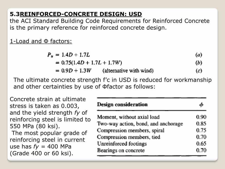
5.3REINFORCED-CONCRETE DESIGN: USD the ACI Standard Building Code Requirements for Reinforced Concrete is the primary reference for reinforced concrete design. 1-Load and Φ factors:
The ultimate concrete strength f’c in USD is reduced for workmanship and other certainties by use of Φfactor as follows:
Concrete strain at ultimate stress is taken as 0.003, and the yield strength fy of reinforcing steel is limited to 550 MPa (80 ksi). The most popular grade of reinforcing steel in current use has fy = 400 MPa (Grade 400 or 60 ksi).
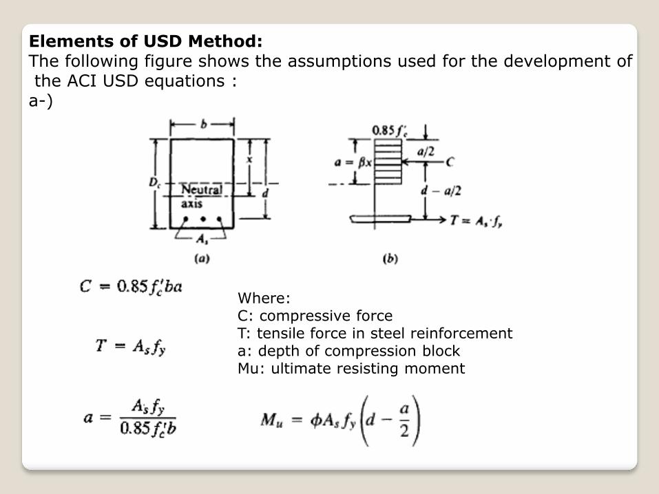
Elements of USD Method: The following figure shows the assumptions used for the development of the ACI USD equations : a-)
Where: C: compressive force T: tensile force in steel reinforcement a: depth of compression block Mu: ultimate resisting moment
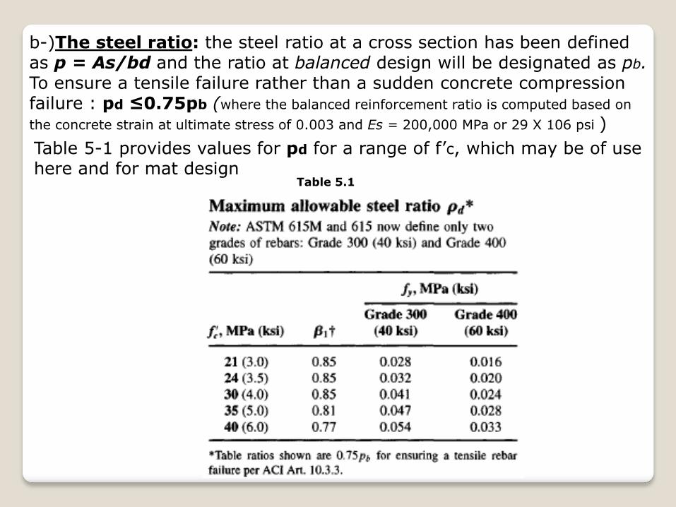
b-)The steel ratio: the steel ratio at a cross section has been defined as p = As/bd and the ratio at balanced design will be designated as pb. To ensure a tensile failure rather than a sudden concrete compression failure : pd ≤0.75pb (where the balanced reinforcement ratio is computed based on
the concrete strain at ultimate stress of 0.003 and Es = 200,000 MPa or 29 X 106 psi )
Table 5.1
Table 5-1 provides values for pd for a range of f’c, which may be of use here and for mat design

C-) Development length: Adequate concrete-to-rebar adhesion (termed bond) is provided by specifying the minimum length of embedment Ld for reinforcing bars in tension depending on diameter or area as follows:
These development lengths should be multiplied by the following factors as applicable:
Table 5.2
Table5.3

The development length for bond (Art. 12.3) for compression bars is the largest of the following:
Standard hooks can be used to reduce the required value of Ld from the preceding equations but are not usually used for footings. d-)Shear: shear often governs the design of spread footings. The ACI Code allows shear to be computed as:

Where: Vu: is the ultimate shear force (factored working loads) bd : is the resisting shear area of width b and effective depth d to center of tension steel. The nominal computed value of shear vu is compared with the allowable values vc, which are wide-beam and two-way action shear defined on table 5.4, The allowable values of vc are as follows:
Table5.4
The ACI Code allows shear reinforcement in footings and it is also obvious that a higher f’c concrete would reduce or eliminate the need for shear reinforcement. Neither of these alternatives is much used; rather, the effective footing depth d is increased to satisfy shear
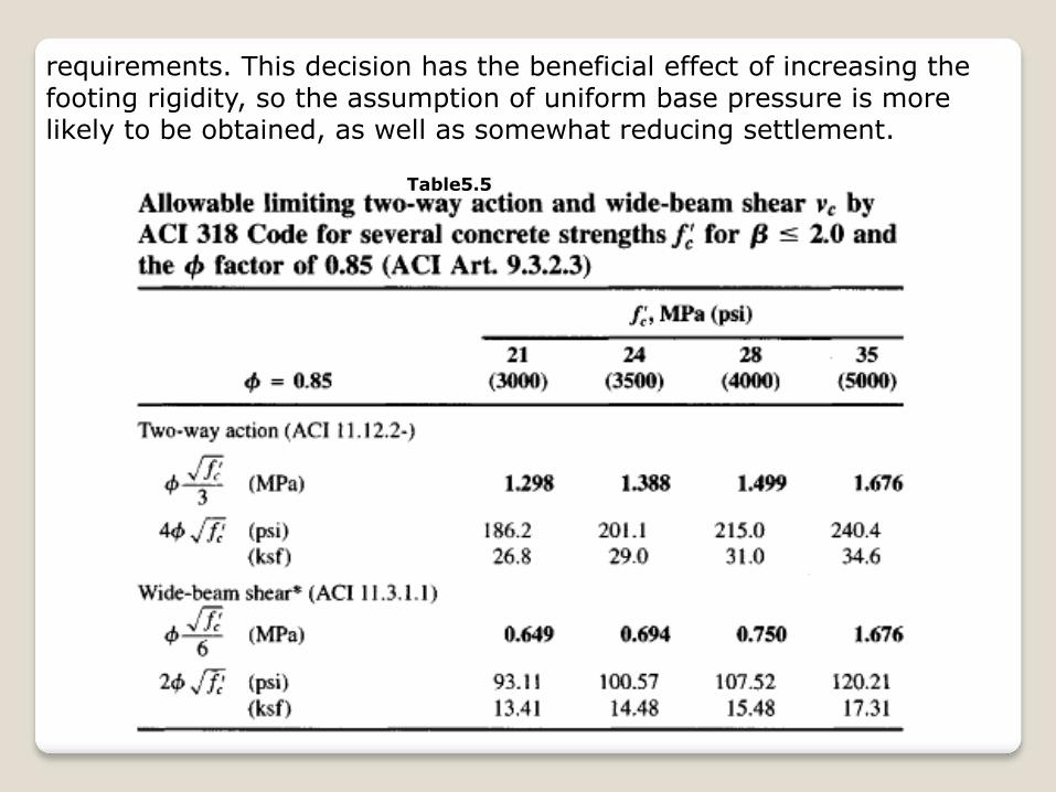
requirements. This decision has the beneficial effect of increasing the footing rigidity, so the assumption of uniform base pressure is more likely to be obtained, as well as somewhat reducing settlement.
Table5.5

Fig.5.1(a)-section for wide beam shear; (b)-section for two way shear action
e-) Dowels: A minimum area of dowels of 0.005Acolumn is required to anchor the column to the footing. Dowels are sometimes required to transfer column stress into the footing, particularly if the column concrete is substantially stronger than the footing concrete.
Fig.5.2

Dowels are required if the column contact stress exceeds the following:
The ratio A2/A1 ≤ 2 and Φ = 0.7. The area A1: is the column contact area (b X c) or ∏a2/4; the area A2 is the base of the frustum that can be placed entirely in the footing as shown in Fig.5.2 The nominal sizes of reinforcing bars commonly used are shown in the following table:
Table 5.6

STRUCTURAL DESIGN OF SPREAD FOOTINGS
The allowable soil pressure controls the plan (B X L) dimensions of a spread footing.
Shear stresses usually control the footing thickness D: - Two-way action shear always controls the depth for centrally loaded
square footings. - Wide-beam shear may control the depth for rectangular footings
when the L/B ratio is greater than about 1.2. Design steps: Step1: Compute the footing plan dimensions B X L or B using the allowable soil pressure:
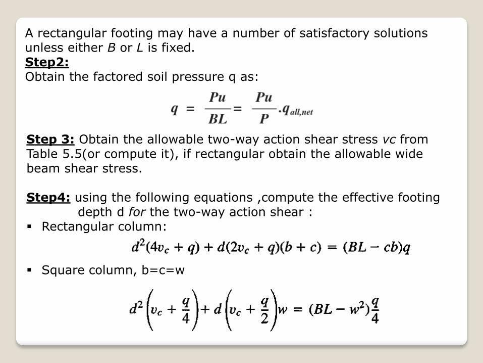
A rectangular footing may have a number of satisfactory solutions unless either B or L is fixed. Step2: Obtain the factored soil pressure q as:
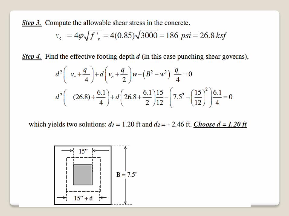
Step 3: Obtain the allowable two-way action shear stress vc from Table 5.5(or compute it), if rectangular obtain the allowable wide beam shear stress. Step4: using the following equations ,compute the effective footing depth d for the two-way action shear : Rectangular column: Square column, b=c=w

Circular column, of diameter a:
These equations were the exact solution, but if we neglect the upward soil pressure on the diagonal tension block, an approximate effective concrete depth d would be: Rectangular column:
Circular column:
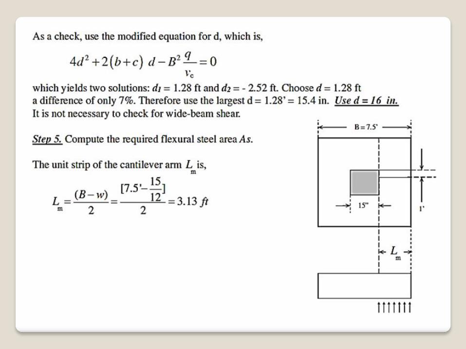
Step5: If the footing is rectangular, immediately check wide-beam shear. Use the larger d from two-way action (step 4) or wide-beam. Step 6: Compute the required steel for bending, and use the same amount each way for square footings.

The bending moment is computed at the critical section. For the cantilever length l shown, the ultimate bending moment/unit width is :
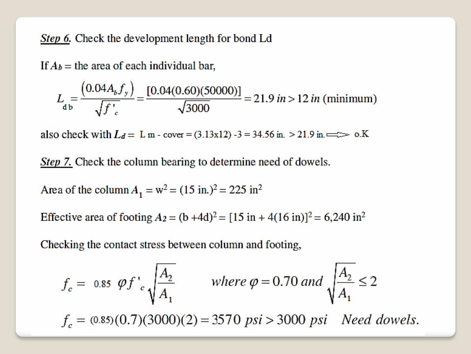
For this Mu, compute the reinforcement As from: Mu=Φ As fy(d-a/2) Check the steel ratio ρ to satisfy shrinkage and temperature, verify that ρ≤ ρd (table5.1)
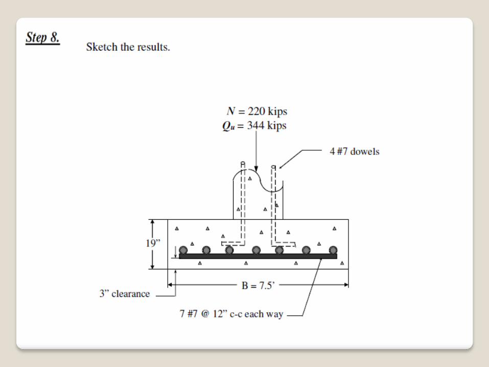
Step7: Compute column bearing and use dowels for bearing if the allowable bearing stress is exceeded. In that case, compute the required dowels: As dowels=(column bearing stress- allowable bearing stress) *column area/Fy. It is necessary always to use a minimum of 0.005Acol of dowel steel regardless of the bearing stress. Step8: Detail the design, provide enough detail that can produce a working drawing for the construction personnel. Remark: one could compute the total steel required and put 60 percent in a column zone with a width of about (w+2d) and the remainder in the two end zones