chlorine institute emergency kit “b” for chlorine ton
TRANSCRIPT

CHLORINE INSTITUTE EMERGENCY KIT “B” FOR CHLORINE TON CONTAINERS Edition 12 January 2021
Kits manufactured after March 2014 Kits manufactured before April 2014
INSTRUCTION BOOKLET Tnc C11LORINE IJ\'STITCTE

i
Table of Contents 1. INTRODUCTION .................................................................................................................... 1
1.1 SCOPE .............................................................................................................................. 1 1.2 CHLORINE INSTITUTE STEWARDSHIP PROGRAM .................................................................. 1 1.3 DISCLAIMER ...................................................................................................................... 1 1.4 APPROVAL ........................................................................................................................ 2 1.5 REVISIONS ........................................................................................................................ 2 1.6 REPRODUCTION ................................................................................................................ 3 1.7 REVISION HISTORY AND COMPATIBILITY .............................................................................. 3
2. GENERAL DESCRIPTION ..................................................................................................... 3
2.1 TRAINING AND SAFETY ....................................................................................................... 3 2.2 RESPIRATORY EQUIPMENT ................................................................................................. 4 2.3 CHLORINE CONTAINER INSPECTION .................................................................................... 4 2.4 VALVE APPLICABILITY ........................................................................................................ 4 2.5 GASKET REPLACEMENT ..................................................................................................... 4 2.6 LEAK DETECTION ............................................................................................................... 4 2.7 ASSISTANCE ...................................................................................................................... 5 2.8 REPORTING REQUIREMENTS .............................................................................................. 5 2.9 EMERGENCY PLAN ............................................................................................................ 5
3. IDENTIFYING AND STOPPING LEAKS ................................................................................ 6
3.1 LEAK: VALVE STEM PACKING (FIGURE 3.1) ......................................................................... 6 3.2 LEAK: THROUGH VALVE SEAT (WILL NOT COMPLETELY CLOSE) (FIGURE 3.1) ....................... 7 3.3 LEAK: VALVE INLET THREADS (FIGURE 3.1) ......................................................................... 7 3.4 LEAK: VALVE STEM ASSEMBLY BLOWN OUT (FIGURE 3.4) .................................................... 8 3.5 LEAK: VALVE BROKEN OFF (FIGURE 3.5) ............................................................................ 8 3.6 LEAK: VALVE BLOWN OUT (DUE TO STRIPPED THREADS) (FIGURE 3.6) ................................. 8 3.7 LEAK: FUSIBLE PLUG THREADS (FIGURE 3.7) ..................................................................... 10 3.8 LEAK: FUSIBLE PLUG BLOWN OUT (FIGURE 3.8) ................................................................ 10 3.9 LEAK: FUSIBLE METAL OF PLUG (FIGURE 3.9) .................................................................... 10 3.10 LEAK: SIDE WALL OF CONTAINER (FIGURE 3.10) ................................................................ 11
4. EMERGENCY KIT “B” MANUFACTURED AFTER MARCH 2014 ...................................... 12
4.1 HOOD VALVES – DEVICE 12 ............................................................................................. 12 4.2 HOOD FOR FUSIBLE PLUGS – DEVICE 14........................................................................... 14 4.3 PATCH FOR SIDE LEAKS – DEVICE 9 ................................................................................. 16
5. EMERGENCY KIT “B” MANUFACTURED BEFORE APRIL 2014 ...................................... 18
5.1 HOOD FOR VALVES – DEVICE 12 ...................................................................................... 18
6. HANDLING OF CHLORINE REMAINING IN CYLINDER ..................................................... 23
7. KIT MAINTENANCE ............................................................................................................. 24
7.1 AFTER USE ..................................................................................................................... 24 7.2 ROUTINE ......................................................................................................................... 24 7.3 SPARE PARTS ................................................................................................................. 24

ii
8. KIT LIMITATIONS ................................................................................................................ 25
8.1 CONTAINER DESIGN ........................................................................................................ 25 8.2 OTHER COMPRESSED GASES ........................................................................................... 25
9. REFERENCES ..................................................................................................................... 26
9.1 INSTITUTE PUBLICATIONS ................................................................................................. 26 9.2 REGULATIONS ................................................................................................................. 26
APPENDIX A: PARTS LIST ........................................................................................................ 28
APPENDIX B: OPTIONAL EQUIPMENT .................................................................................... 32
APPENDIX C: EMERGENCY CONTACTS ................................................................................. 33

EMERGENCY KIT “B” FOR CHLORINE TON CONTAINERS 1
1. INTRODUCTION
Leaks in chlorine containers rarely occur. When they do occur, however, prompt corrective action is required by trained competent personnel with special equipment. The Chlorine Institute Emergency Kit “B” and this instruction booklet are made available by The Chlorine Institute in the belief that they will be helpful in handling such emergencies.
1.1 SCOPE
This instruction booklet provides information on the design and use of the Chlorine Institute Emergency Kit “B”.
1.1.1 Two Generations of Emergency Kit “B”
On January 1, 2014 the design of Emergency Kit “B” was modified for ease of use. This booklet includes instructions on how to apply both the current and previous versions of the tools and devices in Emergency Kit “B”.
1.2 CHLORINE INSTITUTE STEWARDSHIP PROGRAM
The Chlorine Institute exists to support the chlor-alkali industry in advancing safe, secure, environmentally compatible, and sustainable production, distribution, and use of its mission chemicals1.
Chlorine Institute members are committed to adopting CI’s safety and stewardship initiatives, including pamphlets, checklists, and incident sharing, that will assist members in achieving measurable improvement. For more information on the Institute’s stewardship program, visit CI’s website at www.chlorineinstitute.org.
1.3 DISCLAIMER
The information in this booklet is drawn from sources believed to be reliable. The Institute and its members, jointly and severally, make no guarantee, and assume no liability, in connection with any of this information. Moreover, it should not be assumed that every acceptable procedure is included, or that special circumstances may not warrant modified or additional procedures. The user should be aware that changing technology or regulations may require changes in the recommendations contained herein. Appropriate steps should be taken to ensure that the information is current when used. These recommendations should not be confused with federal, state, provincial, municipal, or insurance requirements, or with national safety codes.
1 CI’s mission chemicals: chlorine, sodium and potassium hydroxides, sodium hypochlorite, the distribution of vinyl chloride monomer (VCM), and the distribution and use of hydrogen chloride.

2 IB/B
1.4 APPROVAL
The Institute’s Emergency Preparedness Issue Team approved Edition 12 of this instruction booklet on January 12, 2021.
1.5 REVISIONS
Suggestions for revisions should be directed to the Secretary of the Institute in writing.
1.5.1 Significant Revisions in Current Edition
Significant revisions in Edition 12 of this instruction booklet include:
• Updated CI mission statement (Section 1.2);
• New section to emphasize instructions’ applicability on the standard chlorine valves (Section 2.4);
• New section to further emphasize importance of Viton® gasket replacement (Section 2.5);
• Updated guidance on using aqua ammonia for leak detection (Section 2.6);
• Revised preferred instruction for leaks on valve inlet threads (Section 3.3);
• Revised preferred instruction for leaks on fusible plug threads (Section 3.7);
• Enhanced instruction cautions related to tightening of kit equipment (Sections 4 and 5);
• Enhanced guidance on handling chlorine remaining in containers (Section 6);
• Enhanced guidance on cleaning kit equipment after use (Section 7.1);
• New section providing caution if using kits for compressed gases other than chlorine (Section 8.2);
• New reference section (Section 9);
• Enhanced quality of various images throughout; and
• Minor editorial and formatting updates throughout.

EMERGENCY KIT “B” FOR CHLORINE TON CONTAINERS 3
1.6 REPRODUCTION
The contents of this instruction booklet are not to be copied for publication, in whole or in part, without prior permission from the Secretary of the Chlorine Institute in writing at [email protected].
1.7 REVISION HISTORY AND COMPATIBILITY
Chlorine Institute has published an instruction booklet for the Emergency Kit “B” beginning in 1965. Since then, the kit and booklet have gone through a series of changes. The table below details the updates through the years and device compatibility with current equipment.
Instruction Booklet Edition
Date
Revision Summary
Compatible with Current Containers?
Ed. 12 Jan. 2021 No Kit design change, Booklet updated Yes
Ed. 11, Rev. 1 July 2014 Added Device 400A in the “Optional Equipment” section, which replaced part 400. Yes
Ed. 11 Dec. 2013 Kit Device 12 and 9 modified, Device 14 added Yes
Ed. 10 Jan. 2009 No Kit design change, Booklet updated Yes Ed. 9 June 2003 No Kit design change, Booklet updated Yes Ed. 8 June 1996 No Kit design change, Booklet updated Yes Ed. 7 Oct. 1994 No Kit design change, Booklet updated Yes Ed. 6 1981 No Kit design change, Booklet updated Yes
Ed. 5 July 1978 Included molded Viton gaskets 4-12BMV, 12BBV, 12MV & 9EV Yes
Ed. 4 1976 No Kit design change, Booklet updated Yes Ed. 3 1974 No Kit design change, Booklet updated Yes Ed. 2 1970 No Kit design change, Booklet updated Yes Ed. 1 1965 Booklet created Yes
2. GENERAL DESCRIPTION
The CI Emergency Kit “B” is designed for use with the standard DOT 106A500X chlorine ton container in chlorine service only. These containers have an outside diameter of approximately 30” and overall length from 80 3/4” to 82 1/4”. The Kit is not designed for use on liquid-full ton containers. See Section 8 for additional restrictions when attempting to use Kit-B.
2.1 TRAINING AND SAFETY
Emergency Response and other personnel must be trained in the use of the devices and tools within the CI Emergency Kit “ B”. Training must include the use of respiratory equipment and all other safety equipment. Knowledge of the properties of chlorine is a must.

4 IB/B
Personnel safety is of primary importance. Emergency response should only be performed by authorized personnel who are trained in the procedures and are equipped with suitable respiratory and personal protective equipment.
See current CI Pamphlet 65 for guidance on appropriate personal protective equipment (9.1).
2.2 RESPIRATORY EQUIPMENT
The type of respiratory equipment required will be determined by the severity of the leak and the potential for exposure to chlorine. For further details, see the current edition of CI Pamphlet 65 (9.1).
2.3 CHLORINE CONTAINER INSPECTION
Daily inspection of full containers is recommended whether or not they are connected to unloading lines. Through these means, a leak usually can be detected in an early stage when it can be corrected or controlled by appropriate procedures. Inspection guidance can be found in CI Pamphlet 17 (9.1).
2.4 VALVE APPLICABILITY
The instructions included in this booklet are applicable to containers having standard chlorine ton container valves installed (CGA 820). If another type of valve is installed, consult your supplier or the kit manufacturer for additional instruction details.
2.5 GASKET REPLACEMENT
All Viton® gaskets for the emergency kit are stamped with the date of manufacture and should be removed and replaced every four years (see Section 7 for more details). For further guidelines concerning the Viton gaskets, consult the manufacturer or The Chlorine Institute.
2.6 LEAK DETECTION
As soon as there is any indication of the presence of chlorine in the air, authorized, trained personnel equipped with suitable personal protective equipment should investigate promptly. All other persons should be kept away from the affected area.
The location of a leak in a chlorine containing system can usually be detected by the reaction of ammonia vapor with the escaping chlorine. The reaction is a dense white cloud. The most convenient way to detect a chlorine leak is to use 5-30% aqua ammonia (10.3 – 61.7% ammonium hydroxide solution) in a squeeze bottle.

EMERGENCY KIT “B” FOR CHLORINE TON CONTAINERS 5
Direct the vapors at the suspected leak. To avoid corrosion, the ammonia solution (liquid) should not be directly sprayed onto the container or its connections. Efforts to detect the source of any leak should be carried out with an awareness of the potential hazards and use of necessary personal protective equipment. Note, a weaker solution such as household ammonia, which is typically 5%, may not be concentrated enough to detect minor leaks.
CAUTION
Once the leak is found and you can safely maneuver the container, rotate the container, if needed so that the leak is coming out from the top of the container. Liquid will be on the bottom of the container and gas will be on top. Because chlorine liquid vaporizes and expands into gas by 460 times its volume, it is more manageable to have gas leaking from the cylinder instead of liquid.
2.7 ASSISTANCE
Chlorine emergencies should be handled only by trained personnel at the use site. If assistance is required, promptly notify your supplier. If the supplier cannot be reached or respond immediately, then summon help by activating CHLOREP (The Chlorine Emergency Plan), an emergency response mutual aid network that can be accessed 24/7 for assistance. CHLOREP can be activated by calling CHEMTREC in the U.S. 1-800-424-9300 or CANUTEC in Canada 1-613-996-6666.
2.8 REPORTING REQUIREMENTS
There are federal, state and local government requirements for the reporting of chlorine releases that must be met.
2.9 EMERGENCY PLAN
It is recommended that users have an emergency plan that complies with federal, state and local requirements. For further detail on emergency response plans, refer to CI Pamphlet 155 (9.1).

6 IB/B
3. IDENTIFYING AND STOPPING LEAKS
Figure 3.1
3.1 LEAK: VALVE STEM PACKING (FIGURE 3.1)
ACTION:
1. Ensure valve stem is closed with WRENCH 200B.
2. Tighten packing nut with WRENCH 200B.
3. Test for leaks.
WEAR PERSONAL PROTECTION
OUTLET CAP&
GASKET4G \
"',AC,,NGNUU PACKING
Figure 3.1

EMERGENCY KIT “B” FOR CHLORINE TON CONTAINERS 7
3.2 LEAK: THROUGH VALVE SEAT (WILL NOT COMPLETELY CLOSE) (FIGURE 3.1)
ACTION:
1. If disconnecting from a process, reconnect and firmly open and close valve stem to dislodge foreign matter from seat, with WRENCH 200B, then disconnect and apply outlet cap* and GASKET 4G with WRENCH 200B. (*An outlet cap is included as part of HOOD 12A).
- or -
If unconnected container, apply outlet cap and GASKET 4G, then tighten with WRENCH 200B.
2. Test for leaks.
3.3 LEAK: VALVE INLET THREADS (FIGURE 3.1)
ACTION:
1. Apply DEVICE 12 (Hood and Bar Assembly) (See Section 4.1 for instructions).
2. Test for leaks.
NOTE
Kit “B” contains WRENCH 106 that can be used to tighten the valve back into the cylinder to address this type of leak. Extreme caution should be used when attempting this to avoid making the leak worse by dislodging the valve. Only trained and knowledgeable personnel should ever attempt this procedure. Otherwise, use DEVICE 12.

8 IB/B
Figures 3.4, 3.5, and 3.6
3.4 LEAK: VALVE STEM ASSEMBLY BLOWN OUT (FIGURE 3.4)
ACTION:
1. Drive small DRIFT PIN B-1 into valve body.
2. Test for leaks.
NOTE DEVICE 12 (Hood and Bar Assembly) will probably not fit over the DRIFT PIN B-1. Secure the container in an isolated area and call your chlorine supplier.
3.5 LEAK: VALVE BROKEN OFF (FIGURE 3.5)
ACTION:
1. Drive small DRIFT PIN B-1 into valve shank and apply DEVICE 12 (Hood and Bar Assembly) (See Section 4.1 for instructions).
2. Test for leaks.
3.6 LEAK: VALVE BLOWN OUT (DUE TO STRIPPED THREADS) (FIGURE 3.6)
ACTION:
1. Drive medium DRIFT PIN B-2 into valve opening and apply DEVICE 12 (Hood and Bar Assembly) (See Section 4.1 for instructions).
2. Test for leaks.
PIN B-1
PIN B-2

EMERGENCY KIT “B” FOR CHLORINE TON CONTAINERS 9
Figures 3.7, 3.8, and 3.9
WEAR PERSONAL PROTECTION
104
I __ I
PIN B2 or s3

10 IB/B
3.7 LEAK: FUSIBLE PLUG THREADS (FIGURE 3.7)
ACTION:
1. Apply DEVICE 14 (Hood and Bar Assembly for Fusible Plugs) (See Section 4.2 for instructions).
2. Test for leaks.
NOTE
Kit “B” contains WRENCH 104 that can be used to tighten the fusible plug back into the valve to address this type of leak. Extreme caution should be used when attempting this to avoid making the leak worse by dislodging the fusible plug. Only trained and knowledgeable personnel should ever attempt this procedure. Otherwise, use DEVICE 14.
3.8 LEAK: FUSIBLE PLUG BLOWN OUT (FIGURE 3.8)
If threads of fusible plug are so corroded that plug should pull out:
ACTION:
1. Drive suitable drift pin into fusible plug opening with HAMMER B-6:
Use DRIFT PIN B-2 for fusible plugs with ¾ NPT threads (smaller threads).
- or -
Use DRIFT PIN B-3 for fusible plugs with 1-inch NPT threads (larger threads).
2. Test for leaks.
3.9 LEAK: FUSIBLE METAL OF PLUG (FIGURE 3.9)
ACTION:
1. Apply DEVICE 14 (Hood and Bar Assembly for Fusible Plugs) (See Section 4.2 for instructions).
2. Drive small DRIFT PIN B-1 thru fusible plug.
3. Test for leaks.

EMERGENCY KIT “B” FOR CHLORINE TON CONTAINERS 11
Figure 3.10
3.10 LEAK: SIDE WALL OF CONTAINER (FIGURE 3.10)
ACTION: Apply DEVICE 9 (Patch Assembly) (See Section 4.3 for instructions).
NOTE At all times, before and after application of emergency devices, position container so that the source of the leak is in the gas phase (See Section 4 or 5).

12 IB/B
4. EMERGENCY KIT “B” MANUFACTURED AFTER MARCH 2014
4.1 HOOD VALVES – DEVICE 12
STEPS – See Figure 4.1 Equipment
NOTE: Remove valve protective hood if in place. Position container so that the leaking valve is in the uppermost position.
1. Remove outlet cap from VENT VALVE (12V) on HOOD (12A) and open VALVE (12V).
2. Loosen LOCKING SCREW (28G) on BAR ASSEMBLY (28C) to allow unit to compress and expand fully. Retract SCREW (28D) until point extends slightly beyond bar assembly.
3. Clean head container around leaking valve; use SCRAPER (B-5) if paint is loose or uneven.
4. Place adjustable end of BAR ASSEMBLY (28C) on bottom, inside of chime lip with bar extensions outside chime. Compress assembly downward from atop with handles. Insert upper bar assembly inside upper chime. Reduce resistance to allow unit to expand into the upper chime lip with upper bar extensions resting on outside of chime. Tighten LOCKING SCREW (28G) until hand tight.
NOTE: WRENCH 200B can be used on hex head of LOCKING SCREW (28G) for additional force.
5. Place molded GASKET (4-12BMV) on HOOD (12A). Place HOOD (12A) with molded GASKET (4-12BMV) over leaking valve.
NOTE: For certain containers having a ridge between the two valves, use molded GASKET (12MV) which has a depression to fit over the ridge, or molded GASKET (12BBV).
6. Loosen locking lever on center SCREW (28D) unit and slide over HOOD (12A). Hand tighten forcing HOOD (12A) and GASKET* against head of container. *GASKET 4-12BMV, 12BBV or 12MV
NOTE: WRENCH 200B can be used on hex head of SCREW (28D) for additional force.
CAUTION: Tighten only enough to stop the leak. Overtightening may damage gasket. Wait a short amount of time (allowing container to come back ambient temperature/pressure) to ensure the leak has stopped and the cap screws do not need additional tightening.
WRENCH 200B BAR ASSEMBLY 28C SCRAPER B-5
BAR ASSEMBLY 28C, HOOD 12A
WRENCH 200B
GASKET 4-12BMV
HOOD 12A
WRENCH 200B
DEVICE 12 INCLUDES: HOOD ASSEMBLY - 12A GASKETS – 4-2BMV, 12BBV, or 12MV ADJUSTABLE BAR ASSEMBLY – 28C
WEAR PERSONAL
PROTECTION

EMERGENCY KIT “B” FOR CHLORINE TON CONTAINERS 13
D E V I C E
12 Figure 4.1
DEVICE 12 INSTALLATION
VIDEO
HANDLE~ .·
LOCKING LEVER
SCREW 28D
/ ' LOCKING SCREW
28G
UPPER BAR EXTENSIONS
HOOD 12A
GASKET 4-12BMV

14 IB/B
4.2 HOOD FOR FUSIBLE PLUGS – DEVICE 14
STEPS – See Figure 4.2 Equipment
NOTE: Remove valve protective hood if in place. Position container so that the leaking Plug is in the uppermost position.
1. Loosen LOCKING SCREW (28G) to allow unit to compress and expand fully. Retract SCREW (28D) until point extends slightly beyond bar assembly.
2. Clean head container around leaking fusible plug; use SCRAPER
(B-5) if paint is loose or uneven. 3. Place adjustable end of BAR ASSEMBLY (28C) on bottom, inside of
chime lip with bar extensions outside chime. Compress assembly downward from atop with handles. Insert upper bar assembly inside upper chime. Reduce resistance to allow unit to expand into the upper chime lip with upper bar extensions resting on outside of chime. Tighten LOCKING SCREW (28G) until hand tight.
NOTE: WRENCH 200B can be used on hex head of LOCKING SCREW (28G) for additional force.
4. Place molded GASKET (4-12BMV) on HOOD (14A). Place HOOD (14A) with molded GASKET (4-12BMV) over leaking plug.
5. Loosen locking lever on SCREW (28D) unit and slide over HOOD
(14A). Hand tighten SCREW (28D) forcing HOOD (14A) and GASKET (4-12BMV) against head of container.
NOTE: WRENCH 200B can be used on hex head of SCREW (28D) for additional force. CAUTION: Tighten only enough to stop the leak. Overtightening may damage gasket. Wait a short amount of time (allowing container to come back ambient temperature/pressure) to ensure the leak has stopped and the cap screws do not need additional tightening.
6. Test for leaks.
BAR ASSEMBLY 28C SCRAPER B-5 BAR ASSEMBLY 28C WRENCH 200B GASKET 4-12BMV HOOD 14A WRENCH 200B
DEVICE 14 INCLUDES: HOOD ASSEMBLY – 14A GASKETS – 4-2BMV OR 12BBV ADJUSTABLE BAR ASSEMBLY – 28C
WEAR
PERSONAL PROTECTION

EMERGENCY KIT “B” FOR CHLORINE TON CONTAINERS 15
D E V I C E
14 Figure 4.2
DEVICE 14 INSTALLATION
VIDEO
HANDLE
\
SCREW 28D
LOCKING SCREW
28G
LOCKING LEVER
GASKET 4-12BMV

16 IB/B
4.3 PATCH FOR SIDE LEAKS – DEVICE 9
STEPS – See Figure 4.3 Equipment 1. Roll container so that leak is in uppermost position. Chock container to
prevent rolling. Be sure container wall around leak is sturdy before proceeding with application of device.
NOTE: If container is not on storage rack or rails, place it on rails or 2x4 planks, or dig a trench under it sufficient to allow free passage of strap under the container.
2. Adjust CAP SCREW (9C1) in YOKE (9B) until point of screw extends
only slightly below YOKE (9B). 3. Slip one end of STRAP (9S) under container and pull it through until it
reaches the approximate area of leak. 4. Place BUTTON GASKET (9GV) inside of PATCH (9D1). Center CAP
SCREW (9C1) in YOKE (9B) and then into PATCH (9D1) depression. 5. Hook free ends of STRAP (9S) to ears on each side of YOKE (9B). 6. Use SCRAPER (B-5) if paint is loose or uneven. Slide PATCH
(9D1) with GASKET (9GV) and STRAP (9S) over leak. 7. Hand-tighten CAP SCREW (9C1) until leak stops. Tighten thumb screws
9F until touching cylinder – do not overtighten.
CAUTION: Tighten only enough to stop the leak. Overtightening may damage gasket. Wait a short amount of time (allowing container to come back ambient temperature/pressure) to ensure the leak has stopped and the cap screws do not need additional tightening. CAUTION: If there is any evidence of weakening of the container wall, immediately discontinue tightening CAP SCREW (9C1) and pursue other options.
8. Test for leaks. Tighten CAP SCREW (9C1) further, if necessary.
NOTE: Thumb screws 9F can be tightened independently to apply pressure on the opposite sides of gasket to stop leak.
YOKE 9B CAP SCREW 9C1 STRAP 9S YOKE 9B CAP SCREW 9C1 PATCH 9D1 STRAP 9S SCRAPER B-5 PATCH 9D1 GASKET 9GV
DEVICE 9 INCLUDES: STRAP – 9S YOKE – 9B CAP SCREW – 9C1 PATCH – 9D1 GASKET – 9GV
WEAR PERSONAL PROTECTION

EMERGENCY KIT “B” FOR CHLORINE TON CONTAINERS 17
D E V I C E 9
Figure 4.3
DEVICE 9 INSTALLATION
VIDEO
CAP SCREW
9C1
PATCH~ 901
CAP SCREW 9C1
YOKE /9B THUMB
SCREWS
✓ 9F
........__ GASKET --............. 9GV

18 IB/B
i 2
5. EMERGENCY KIT “B” MANUFACTURED BEFORE APRIL 2014 5.1 HOOD FOR VALVES – DEVICE 12
STEPS – See Figure 5.1 Equipment NOTE: Remove valve protective hood if in place. Position container so that the leaking valve is in the uppermost position. 1. Remove outlet cap from VENT VALVE (12V) on HOOD (12A) and
open VALVE (12V). 2. Loosen ADJUSTING SCREWS (12F) and retract JACK SCREWS
(12E) sufficiently to allow insertion of ADJUSTABLE BAR ASSEMBLY (12C) behind chime of container.
NOTE: ADJUSTABLE ASSEMBLY (12C) must be in vertical position to facilitate making adjustments.
3. Clean head container around leaking valve; use SCRAPER (B-5) if
paint is loose or uneven. 4. Place molded GASKET (4-12BMV) on HOOD (12A). Place
HOOD (12A) with molded GASKET (4-12BMV) over leaking valve.
NOTE: For certain containers having a ridge between the two valves, use molded GASKET (12BBV) or molded GASKET (12MV) which has a depression to fit over the ridge.
5. Adjust lower JACK SCREW (12E) to center one CAP SCREW
(12D) over HOOD (12A) and adjust upper JACK SCREW (12E) so that ADJUSTABLE BAR ASSEMBLY (12C) fits tightly inside chime. Using WRENCH (101) tighten ADJUSTING SCREWS (12F).
6. Using WRENCH (101) tighten CAP SCREW (12D) forcing
HOOD (12A) and GASKET* against head container. *GASKET 4-12BMV or 12BBV or 12MV
CAUTION: Tighten only enough to stop the leak. Overtightening may damage gasket. Wait a short amount of time (allowing container to come back ambient temperature/pressure) to ensure the leak has stopped and the cap screws do not need additional tightening.
7. Close VENT VALVE (12V) on HOOD (12A) using WRENCH (200).
WRENCH 200 BAR ASSEMBLY 12C WRENCH 101 SCRAPER B-5 HOOD 12A GASKET 4-12BMV WRENCH 101 BAR ASSEMBLY 12C WRENCH 101 CAP SCREW 12D HOOD 12A WRENCH 200
DEVICE 12 INCLUDES: HOOD ASSEMBLY – 12A GASKETS – 4-12BMV, 12BBV, OR 12MV ADJUSTABLE BAR ASSEMBLY – 12C
WEAR PERSONAL PROTECTION

EMERGENCY KIT “B” FOR CHLORINE TON CONTAINERS 19
D E V I C E
12
Figure 5.1
ADUSTING SCREW 12F
JACK SCREW 12E
BAR ASSEMBLY 12C
CAP SCREW 12D
VENT VALVE 12V
HOOD I
12A
GASKET: 4-12BMV OR 12BBV OR 12MV
20 IB/B
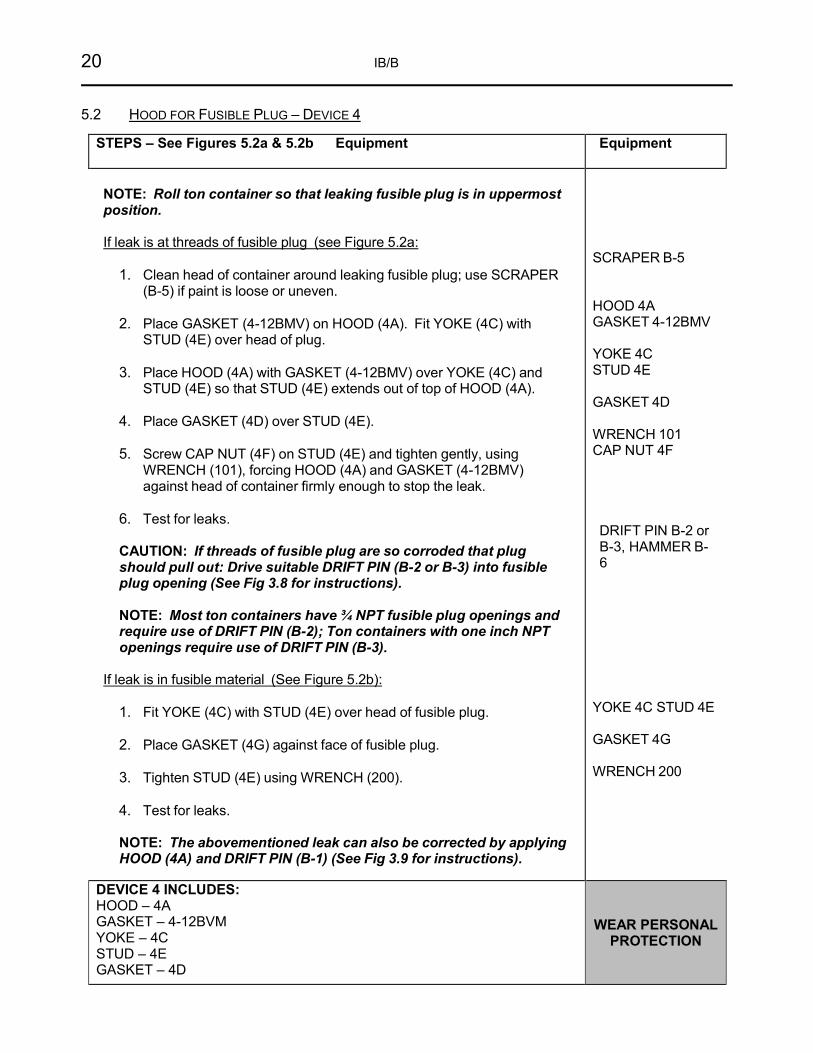
5.2 HOOD FOR FUSIBLE PLUG – DEVICE 4
STEPS – See Figures 5.2a & 5.2b Equipment Equipment
NOTE: Roll ton container so that leaking fusible plug is in uppermost position.
If leak is at threads of fusible plug (see Figure 5.2a:
1. Clean head of container around leaking fusible plug; use SCRAPER
(B-5) if paint is loose or uneven. 2. Place GASKET (4-12BMV) on HOOD (4A). Fit YOKE (4C) with
STUD (4E) over head of plug. 3. Place HOOD (4A) with GASKET (4-12BMV) over YOKE (4C) and
STUD (4E) so that STUD (4E) extends out of top of HOOD (4A). 4. Place GASKET (4D) over STUD (4E). 5. Screw CAP NUT (4F) on STUD (4E) and tighten gently, using
WRENCH (101), forcing HOOD (4A) and GASKET (4-12BMV) against head of container firmly enough to stop the leak.
6. Test for leaks.
CAUTION: If threads of fusible plug are so corroded that plug should pull out: Drive suitable DRIFT PIN (B-2 or B-3) into fusible plug opening (See Fig 3.8 for instructions). NOTE: Most ton containers have ¾ NPT fusible plug openings and require use of DRIFT PIN (B-2); Ton containers with one inch NPT openings require use of DRIFT PIN (B-3).
If leak is in fusible material (See Figure 5.2b):
1. Fit YOKE (4C) with STUD (4E) over head of fusible plug. 2. Place GASKET (4G) against face of fusible plug. 3. Tighten STUD (4E) using WRENCH (200). 4. Test for leaks.
NOTE: The abovementioned leak can also be corrected by applying HOOD (4A) and DRIFT PIN (B-1) (See Fig 3.9 for instructions).
SCRAPER B-5 HOOD 4A GASKET 4-12BMV YOKE 4C STUD 4E GASKET 4D WRENCH 101 CAP NUT 4F DRIFT PIN B-2 or B-3, HAMMER B-6
YOKE 4C STUD 4E GASKET 4G WRENCH 200
DEVICE 4 INCLUDES: HOOD – 4A GASKET – 4-12BVM YOKE – 4C STUD – 4E GASKET – 4D
WEAR PERSONAL PROTECTION

EMERGENCY KIT “B” FOR CHLORINE TON CONTAINERS 21
D E V I C E 4
Figures 5.2a and 5.2b
Fig. 5.2a
GASKET 4-12BMV
_,,,,-- HOOD 4A
CAP NUT 4F
STUD 4E
GASKET4D
FUSIBLE PLUG
STUD 4E
YOKE 4C
22 IB/B
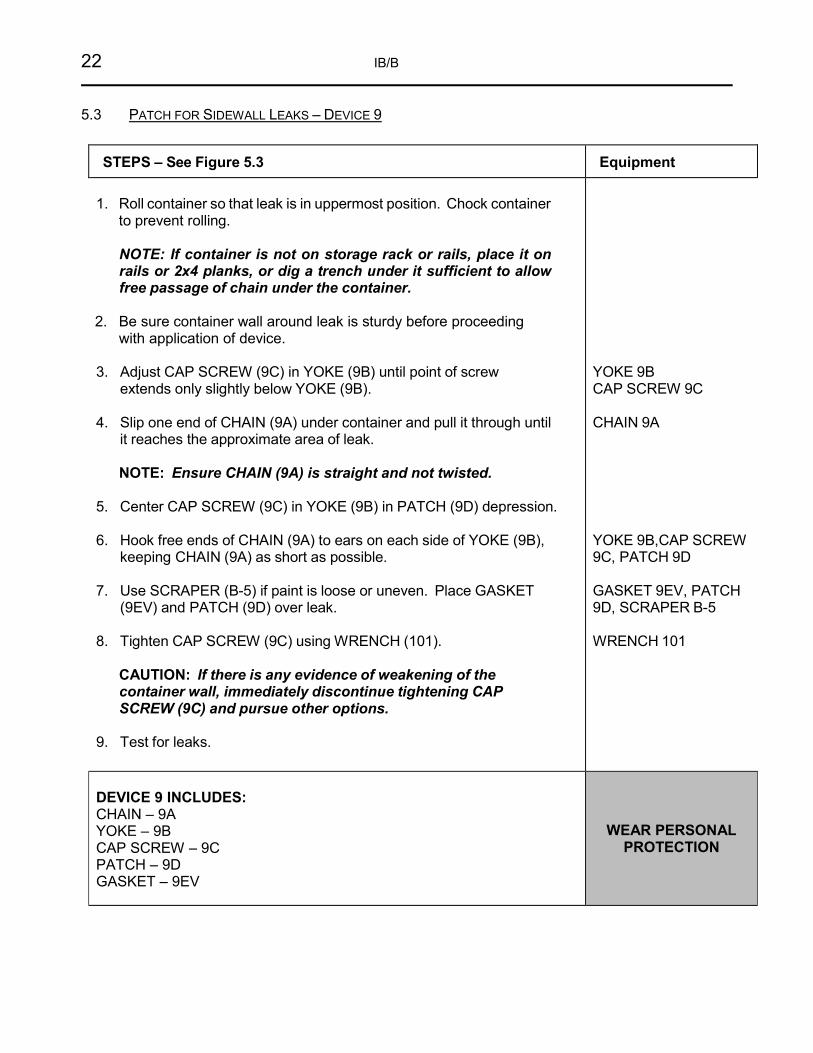
5.3 PATCH FOR SIDEWALL LEAKS – DEVICE 9
STEPS – See Figure 5.3 Equipment
1. Roll container so that leak is in uppermost position. Chock container to prevent rolling.
NOTE: If container is not on storage rack or rails, place it on rails or 2x4 planks, or dig a trench under it sufficient to allow free passage of chain under the container.
2. Be sure container wall around leak is sturdy before proceeding
with application of device.
3. Adjust CAP SCREW (9C) in YOKE (9B) until point of screw extends only slightly below YOKE (9B).
4. Slip one end of CHAIN (9A) under container and pull it through until
it reaches the approximate area of leak.
NOTE: Ensure CHAIN (9A) is straight and not twisted. 5. Center CAP SCREW (9C) in YOKE (9B) in PATCH (9D) depression. 6. Hook free ends of CHAIN (9A) to ears on each side of YOKE (9B),
keeping CHAIN (9A) as short as possible. 7. Use SCRAPER (B-5) if paint is loose or uneven. Place GASKET
(9EV) and PATCH (9D) over leak.
8. Tighten CAP SCREW (9C) using WRENCH (101).
CAUTION: If there is any evidence of weakening of the container wall, immediately discontinue tightening CAP SCREW (9C) and pursue other options.
9. Test for leaks.
YOKE 9B CAP SCREW 9C CHAIN 9A YOKE 9B,CAP SCREW 9C, PATCH 9D GASKET 9EV, PATCH 9D, SCRAPER B-5 WRENCH 101
DEVICE 9 INCLUDES: CHAIN – 9A YOKE – 9B CAP SCREW – 9C PATCH – 9D GASKET – 9EV
WEAR PERSONAL PROTECTION

EMERGENCY KIT “B” FOR CHLORINE TON CONTAINERS 23
D E V I C E 9
Figure 5.3
6. HANDLING OF CHLORINE REMAINING IN CONTAINER The containment of leaks by the CI Emergency Kit “B” devices is only an interim measure.
The containment of leaks by the CI Emergency Kit B devices is only an interim measure. VALVE YOKE (B-9) and VALVE ADAPTER (B-10) are included in this kit for use in disposing of remaining chlorine in a capped container. This procedure should be attempted by experienced personnel only.
YOKE 9B
GASKEF 9EV
CHAIN 9A

24 IB/B
CONSULT WITH THE CHLORINE SUPPLIER IMMEDIATELY AND ARRANGE FOR ULTIMATE DISPOSAL.
If supplier is unknown, see Section 2.7 for instructions to contact CHLOREP for immediate assistance.
If the ton container requires transport to another facility for disposal, it is important to be familiar with applicable transportation regulations. If the container is safe for transport, it may be transported in the U.S. with Kit “B” devices applied (see 49 CFR §173.3(e)(2)), as well in Canada (see TP 14877, Section 11.4.1).
7. KIT MAINTENANCE
NOTE All parts of the CI Emergency Kit “B” should be maintained in a ready-to-use condition.
7.1 AFTER USE
Inspect all parts for damage, wear, and corrosion. Wash all parts used with approximately 5% solution of caustic soda or soda ash to neutralize any residual chlorine. After washing, rinse parts with water until they are free of cleaning solution. Dry all parts once free of cleaning solution.
Lubricate moveable parts with a non-reactive lubricant. Refer to CI Pamphlet 164 (9.1) for information on lubricant materials that are compatible with chlorine.
Replace all gaskets used. Inspect side patch strap after use for wear and replace as necessary.
7.2 ROUTINE
The kit should be frequently inspected by the person responsible for the equipment and checked with the contents list to ensure that equipment is complete and ready for use. The box should be sealed after each inspection and such seals should be broken only by authorized persons or in case of accidents. Many owners coordinate routine inspection with training drills.
All Viton gaskets are stamped with the date of manufacture and should be removed from emergency use after a four-year shelf life. For further guidelines concerning the Viton gaskets, consult the manufacturer or The Chlorine Institute.
7.3 SPARE PARTS
Spare parts may be purchased by owners of this kit from the manufacturer. For information on ordering procedures consult the manufacturer or The Chlorine Institute.

EMERGENCY KIT “B” FOR CHLORINE TON CONTAINERS 25
8. KIT LIMITATIONS
8.1 CONTAINER DESIGN
Some ton containers in current use are of such design that application of Kit B devices might be difficult or impossible. Among these are containers with double-dished heads; with fusible plugs located too close to valve protective hood lugs (precluding proper placement of Device 14); with fusible plugs located radially from the center of the head too close to the chime (precluding proper placement of Device 14); with valve protection hood fastened by means of a single stud located between the two operating valves (precluding use of Device 12); and with oversized valve bushing (precluding proper seating of gasket 4-12BMV, 12BBV or 12MV and of Hood Assembly 12A).
8.2 OTHER COMPRESSED GASES
The CI Emergency Kit “B” is designed for use on chlorine cylinders. Contact the kit manufacturer before considering applying on other compressed gas cylinders.
CAUTION Using Emergency Kit “B” for other ton containers transporting compressed gas can result in a worsening incident due to incompatibility of materials provided in the kit.
Different gasket materials may be required for other compressed gases. When used with compressed gases other than chlorine, the Viton gasket included with this kit may result in rapid deterioration and continued release.

26 IB/B
9. REFERENCES
9.1 INSTITUTE PUBLICATIONS
The following publications are specifically referenced in the CHLOREP Handbook. The latest editions of CI publications may be obtained at www.chlorineinstitute.org.
Pamphlet # Title
1 Chlorine Basics (Formerly The Chlorine Manual), ed. 8; Pamphlet 1; The Chlorine Institute: Arlington, VA, 2014.
17 Packaging Plant Safety and Operational Guidelines, ed. 5; Pamphlet 17; The Chlorine Institute: Arlington, VA, 2017.
65 Personal Protective Equipment for Chlor-Alkali Chemicals, ed. 6; Pamphlet 65; The Chlorine Institute: Arlington, VA, 2021.
155 Water and Wastewater Operators Chlorine Handbook, ed. 3; Pamphlet 155; The Chlorine Institute: Arlington, VA, 2014.
164 Reactivity and Compatibility of Chlorine and Sodium Hydroxide with Various Materials, ed. 3; Pamphlet 164; The Chlorine Institute: Arlington, VA, 2017.
9.2 REGULATIONS
9.2.1 Code of Federal Regulations. Title 49. Chapter 1. Parts 190-192 & 195. Office of the Federal Register National Archives and Records Administration. U.S. Government Printing Office: Washington, DC, (revised annually).
9.2.2 Canadian Transportation of Dangerous Goods Act and Regulations; Transport Canada: Ottawa, Ontario, 2009. Website: http://www.tc.gc.ca/tdg.

EMERGENCY KIT “B” FOR CHLORINE TON CONTAINERS 27
APPENDICES
Appendix A: Parts List
Appendix B: Optional
Equipment
Appendix C: Emergency Contacts

28 IB/B
APPENDIX A: PARTS LIST
Chlorine Institute Emergency Kit “B” Kits Manufactured After March 2014
Part Number Description Quantity Per Kit
4-12BMV Gasket, Molded Viton 2 4G Gasket, 15/16” dia. x 1/16” thick 5 9S Strap 1 9B Yoke 1 9C1 Cap Screw 1 9D1 Patch 1 9GV Gasket, Viton, 1 7/16” diameter x ¾” thick 2 12A Hood Assembly (with Vent Valve 12V) 1 12BBV Gasket, Viton, 5” OD x 2” ID x ½” thick 1 28C Adjustable Bar Assembly 1 12MV Gasket, Molded Viton, 5 ¼” OD x 2 ¼” ID x ¾” thick 1 14A Hood 1 101 Wrench, straight open end, 1 ¼” x 12" long 1 104 Wrench, Socket, 1 ¼” hex x 11” long 1 104B Wrench Bar, 1" diameter x 20" long 1 106 Wrench, Crowfoot, special 1 5/32” x 11" long 1 200B Wrench, 3/8 sq. box, 1 ¼” open end x 7 ¼” long 1 B-1 Drift Pin, 9/32” x ½” x 6" long 2 B-2 Drift Pin, 7/8” x 1 ¼” x 8" long 2 B-3 Drift Pin, 1 1/16” x 1 7/16” x 8" long 2 B-4 Ring, vent valve packing, 7/8” OD x 15/32” ID x ¼” thick 5 B-5 Paint Scraper, 1 ¼” blade 1 B-6 Hammer, machinist, 48 oz. 1 B-7 Kit Box Seal 15 B-8 Gasket Sack 1 B-9 Valve Yoke 1 B-10 Valve Adapter 1 B-11 Gasket, 15/16” OD x 9/16” ID x 1/16” thick 5 B-12 Plastic Gasket Box 1 151-B Kit Tool Box 1 153 Tool Roll 1 Instruction Booklet 2 CI Pamphlet 1, Chlorine Basics 1
For kits manufactured after January 1, 2008, the individual 1” drive components of Socket Wrench Assembly 104 were replaced with a completely machined, 1-piece wrench. Viton is a registered trademark of The Chemours Company.

EMERGENCY KIT “B” FOR CHLORINE TON CONTAINERS 29
CHLORINE INSTITUTE EMERGENCY KIT “B”
Kits Manufactured after March 2014
Figure A-1
O~C!O I :rff lllllf~if~ •
111

30 IB/B
Chlorine Institute Emergency Kit “B” Kits Manufactured Before April 2014
Part Number Description
Quantity Per Kit
4A Hood 1 4-12BMV Gasket, Molded Viton 2 4C Yoke 1 4D Gasket, 1 ¼” OD x 11/16” ID x 1/16” thick 3 4E Stud 1 4F Cap Nut 1 4G Gasket, 15/16” diameter x 1/16” thick 5 9A Chain 1 9B Yoke 1 9C Cap Screw 1 9D Patch 1 9EV Gasket, Viton, 3" sq. x 1/8” thick 2 12A Hood Assembly (with Vent Valve 12V) 1 12BBV Gasket, Viton, 5” OD x 2” ID x ½” thick 1 12C Adjustable Bar Assembly 1 12MV Gasket, Molded Viton, 5 ¼” OD x 2 ¼” ID x ¾” thick 1 101 Wrench, straight open end, 1 ¼” x 12" long. 1 104 Wrench, Socket, 1 ¼” hex x 11” long 1 104A Wrench extension, 1" sq. drive x 9" long 1 104B Wrench Bar, 1" diameter x 20" long 1 104C Wrench Bar, Adapter, 1" round to 1" square 1 106 Wrench, Crowfoot, special 1 5/32” x 11" long 1 200 Wrench, 3/8” sq. box, 1 ¼” open end x 7 ¼” long 1 B-1 Drift Pin, 9/32” x ½” x 6" long 2 B-2 Drift Pin, 7/8” x 1 ¼” x 8" long 2 B-3 Drift Pin, 1 1/16” x 1 7/16” x 8" long 2 B-4 Ring, vent valve packing, 7/8” OD x 15/32” ID x ¼” thick 5 B-5 Paint Scraper, 1 ¼” blade 1 B-6 Hammer, machinist, 48 oz. 1 B-7 Kit Box Seal 15 B-8 Gasket Sack 1 B-9 Valve Yoke 1 B-10 Valve Adapter 1 B-11 Gasket, 15/16” OD x 9/16” ID x 1/16” thick 5 B-12 Plastic Gasket Box 1 151-B Kit Tool Box 1 153 Tool Roll 1 Instruction Booklet 2 CI Pamphlet 1, Chlorine Basics 1
For kits manufactured after January 1, 2008, the individual 1” drive components of socket wrench assembly 104 were replaced with a completely machined, 1-piece wrench.
Viton is a registered trademark of The Chemours Company.

EMERGENCY KIT “B” FOR CHLORINE TON CONTAINERS 31
CHLORINE INSTITUTE EMERGENCY KIT “B”
Kits Manufactured before March 2014
Figure A-2
CHLORINE INSTITUTE ENIEROIENCV KIT " B ..
F OR CHLORIN E TON CONTAIN E R S

32 IB/B
Device Part #BCLAMP
Fusible Plug Containment Device: Designed to contain leaks in and around the container
fusible plugs without attaching to the plug itself.
APPENDIX B: OPTIONAL EQUIPMENT If the optional equipment shown here is used, consult the kit manufacturer for instruction details.
Device Part #400A Device Part #405
Stripped Valve Stem Clamping Device:
Designed to close cylinder and ton valves with stripped valve stem threads.
Valve Plugging Device:
Designed to seal leaks in valves with stripped outlet threads or corroded outlet face.

EMERGENCY KIT “B” FOR CHLORINE TON CONTAINERS 33
APPENDIX C: EMERGENCY CONTACTS
Chlorine Supplier:
Address:
Phone:
CHEMTREC* 800-424-9300
CANUTEC** 613-996-6666
Nearest Chlorine
Producer or Packager:
Address:
Phone:
Police Department:
Fire Department:
First Aid:
* In the UNITED STATES, summon help through CHEMTREC, the Chemical Transportation Emergency Center at the American Chemistry Council in Arlington, VA.
(Toll Free) 800-424-9300 ** In CANADA, summon help through CANUTEC, the Canadian Transport Emergency Centre in Ottawa.
CANADA, All provinces (Call Collect) 613-996-6666

1300 Wilson Boulevard • Suite 525 • Arlington, VA 22209 Telephone: (703) 894-4140 Email: [email protected] Website: www.chlorineinstitute.org Technical Inquiries: [email protected]
The Chlorine Institute all rights reserved.
THE CHLORINE INSTITUTE