chiptuning car installation instructions - diesel … · chiptuning car installation instructions...
TRANSCRIPT

Chiptuning CAR Installation Instructions
Version 3 / Stand 12.03.2015 / English
System>> CRD14-System LDK-18 / 10556218
ENG20006
Chiptuning CAR Installation Instructions
Version 3 / Stand 12.03.2015 / English
Chiptuning CAR Installation Instructions
Version 3 / Stand 12.03.2015 / English
Table of Contents
Preliminary>>
>>
The Performance Pack is specifically tuned and programmed for your vehicle. Due to productionvariations, the expected result of the Performance Pack can turn out differently (higher or lower). Also, theincreased performance always depends on the maintenance condition and mileage of the vehicle.
If the power is too high, shown by a strong soot formation, disturbed engine run, engine misfire or the initiation of the engine emergency manifests itself: a program change is possible (see page 5). IMPORTANT: When changing the program contact your dealer or manufacturer!
Scope of delivery>>
Scope of delivery / Preliminary 3
General instructions 4
Installation principle 5
Changing Programs 6
Trouble shooting 7
Installation example 8
Performance Pack
Harness
Dummy plug
Fixing Set
Sticker
Installation Instructions
3
Chiptuning CAR Installation Instructions
Version 3 / Stand 12.03.2015 / English
Read this installation guide carefully before starting the installation so that you will be able to use all the technical advantages of the systems and do not start with the installation before you have read and understood the instructions.
If you comply with the advice given below (1) you will avoid an early termination of the product guarantee and you will be enjoying your product for years to come.
(2) Never install the system if the ignition is on. Pull the ignition key.
(3) After switching off the ignition, wait for 5 minutes until all electric devices are turned off.
(4) If possible, install the module in a dry area in the engine compartment. Humidity and wetnesscontain minerals which cause corrosion to the electronic circuits. Fix the harness and protect itfrom humidity.
(5) Before every engine wash, remove the entire tuning system.
(6) Do not fix tuning systems to engine parts that could heat up. Never fix the module directly or closeto the engine (engine block). High temperatures can reduce the lifespan of electronic devices and candeform or melt specific plastics materials.
(7) Take care that the harness does not touch the parts in motion and the metal parts to avoid friction.Do not make any changes to the harness (do not make it any longer or shorter).
(8) In case of the malfunctioning of the system due to any non‐compliance with the instructions duringthe installation of the tuning modules, the product guarantee will be terminated.
General instructions>>
4
Chiptuning CAR Installation Instructions
Version 3 / Stand 12.03.2015 / English
Installation principle
Installation>>
>>
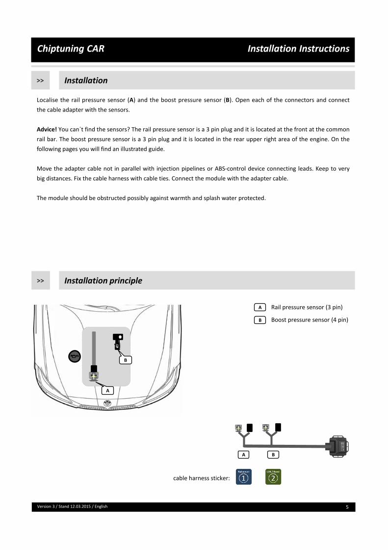
Localise the rail pressure sensor (A) and the boost pressure sensor (B). Open each of the connectors and connect
the cable adapter with the sensors.
Advice! You can´t find the sensors? The rail pressure sensor is a 3 pin plug and it is located at the front at the common
rail bar. The boost pressure sensor is a 3 pin plug and it is located in the rear upper right area of the engine. On the
following pages you will find an illustrated guide.
Move the adapter cable not in parallel with injection pipelines or ABS-control device connecting leads. Keep to very
big distances. Fix the cable harness with cable ties. Connect the module with the adapter cable.
The module should be obstructed possibly against warmth and splash water protected.
5
A
B
Rail pressure sensor (3 pin)
Boost pressure sensor (4 pin)
cable harness sticker:
1
A B
A
B

Chiptuning CAR Installation Instructions
Version 3 / Stand 12.03.2015 / English
Program Adjustments>>
You purchased a Chiptuning module for your vehicle. This module already includes a vehicle specific tuning. If you need to alter this setup, then follow the instructions below.
Remarks:
• The module is delivered with the best tuning possible for your vehicle, therefore it is not necessary to change the setup.
• Before you make any changes to the setup, you should always contact your dealer or manufacturer in advance.
• When the LEDs are flashing, the buttons of the keypad are locked. • Each tuning setup can be increased or decreased by three stages using the + and – buttons.• The LEDs on the module have an important role during the program change. They will indicate which
tuning program you have selected with which fine adjustment.
Step 1: Unlocking the Keypad
When the module is active, you will notice that thefirst LED above P (= Program) flashes red at position 1(= Pos. 1). This indicates that tuning program 1 isselected (see Fig. A).Before making a program change, press and hold the +and – buttons simultaneously for 5 seconds to unlockthe keypad.
Important: Press and hold the + and – buttons until all9 LEDs light up simultaneously (see Fig. B). Only thenshould you let go of the buttons and start changing theprogram.
Step 2: Changing the tuning program
The various tuning programs are represented bydifferent color LEDs above the P button as shown inFig. C.
If you press the P button, after unlocking the keypad,you will see the LEDs switch from red (= Program 1[Sports]) to yellow (= Program 2 [Dynamic]).When pressed again the LEDs will switch from yellowto green (= Program 3 [Efficency]).
Pressing the P button for a third time the LEDs will turnoff. This indicates there is no tuning program selected.If you continue to press the P button you will gothrough the program selection in the same order.
Fig. A
Fig. B
Fig. C
6
Chiptuning CAR Installation Instructions
Version 3 / Stand 12.03.2015 / English
Program Adjustments>>
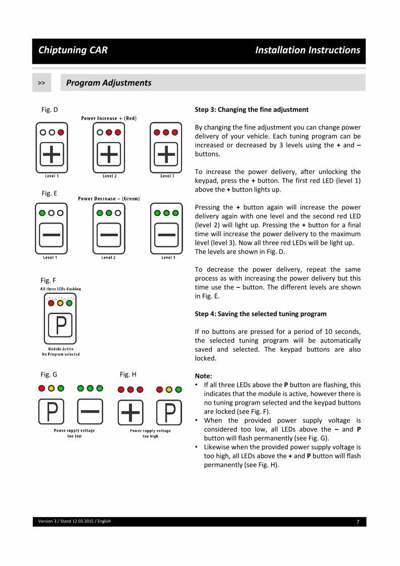
Step 3: Changing the fine adjustment
By changing the fine adjustment you can change powerdelivery of your vehicle. Each tuning program can beincreased or decreased by 3 levels using the + and –buttons.
To increase the power delivery, after unlocking thekeypad, press the + button. The first red LED (level 1)above the + button lights up.
Pressing the + button again will increase the powerdelivery again with one level and the second red LED(level 2) will light up. Pressing the + button for a finaltime will increase the power delivery to the maximumlevel (level 3). Now all three red LEDs will be light up.The levels are shown in Fig. D.
To decrease the power delivery, repeat the sameprocess as with increasing the power delivery but thistime use the – button. The different levels are shownin Fig. E.
Step 4: Saving the selected tuning program
If no buttons are pressed for a period of 10 seconds,the selected tuning program will be automaticallysaved and selected. The keypad buttons are alsolocked.
Note:• If all three LEDs above the P button are flashing, this
indicates that the module is active, however there isno tuning program selected and the keypad buttonsare locked (see Fig. F).
• When the provided power supply voltage isconsidered too low, all LEDs above the – and Pbutton will flash permanently (see Fig. G).
• Likewise when the provided power supply voltage istoo high, all LEDs above the + and P button will flashpermanently (see Fig. H).
Fig. D
Fig. E
Fig. F
Fig. G Fig. H
7
Chiptuning CAR Installation Instructions
Version 3 / Stand 12.03.2015 / English
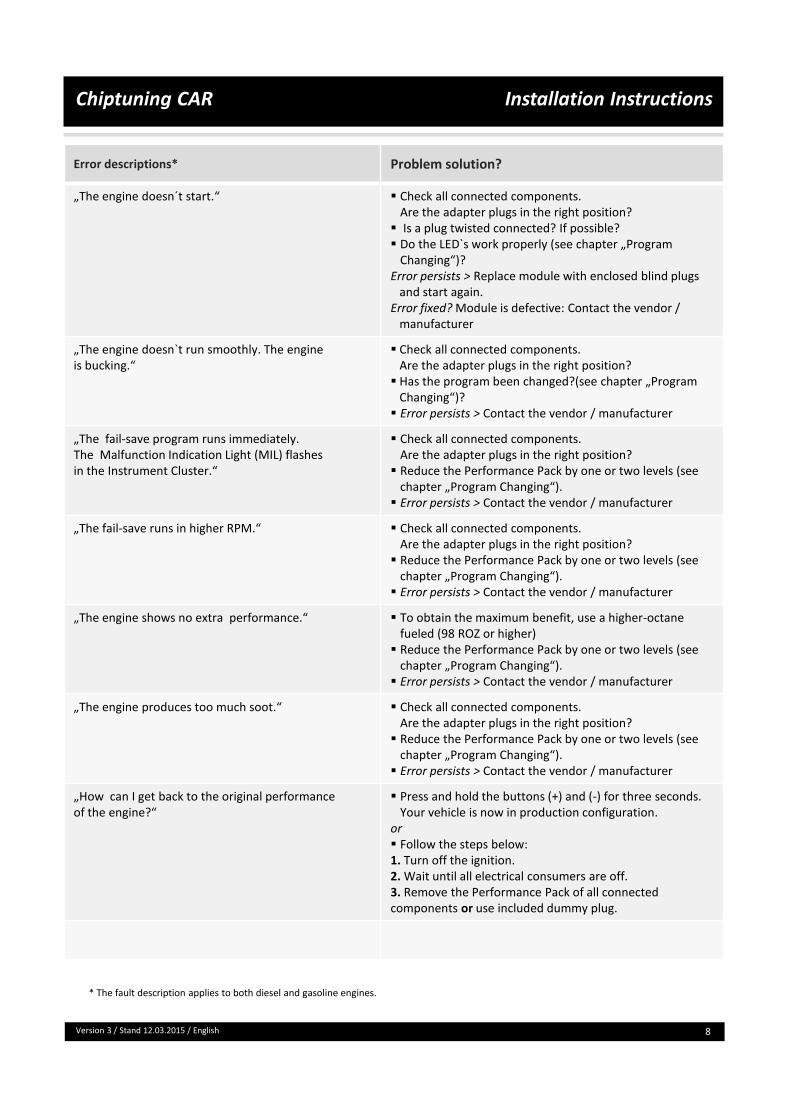
Error descriptions* Problem solution?
„The engine doesn´t start.“ Check all connected components.Are the adapter plugs in the right position?
Is a plug twisted connected? If possible? Do the LED`s work properly (see chapter „Program
Changing“)? Error persists > Replace module with enclosed blind plugs
and start again.Error fixed? Module is defective: Contact the vendor /
manufacturer
„The engine doesn`t run smoothly. The engine is bucking.“
Check all connected components.Are the adapter plugs in the right position?
Has the program been changed?(see chapter „Program Changing“)?
Error persists > Contact the vendor / manufacturer
„The fail-save program runs immediately. The Malfunction Indication Light (MIL) flashes in the Instrument Cluster.“
Check all connected components.Are the adapter plugs in the right position?
Reduce the Performance Pack by one or two levels (see chapter „Program Changing“).
Error persists > Contact the vendor / manufacturer
„The fail-save runs in higher RPM.“ Check all connected components.Are the adapter plugs in the right position?
Reduce the Performance Pack by one or two levels (see chapter „Program Changing“).
Error persists > Contact the vendor / manufacturer
„The engine shows no extra performance.“ To obtain the maximum benefit, use a higher-octane fueled (98 ROZ or higher)
Reduce the Performance Pack by one or two levels (see chapter „Program Changing“).
Error persists > Contact the vendor / manufacturer
„The engine produces too much soot.“ Check all connected components.Are the adapter plugs in the right position?
Reduce the Performance Pack by one or two levels (see chapter „Program Changing“).
Error persists > Contact the vendor / manufacturer
„How can I get back to the original performance of the engine?“
Press and hold the buttons (+) and (-) for three seconds. Your vehicle is now in production configuration.
or Follow the steps below:1. Turn off the ignition.2. Wait until all electrical consumers are off.3. Remove the Performance Pack of all connected components or use included dummy plug.
* The fault description applies to both diesel and gasoline engines.
8

Chiptuning CAR Installation Instructions
Version 3 / Stand 12.03.2015 / English
Installation example>>
9
Open the engine hood. Remove the engine
over (D).
Remove the protective cover (R).
Localise the rail pressure bar (B). The 3 pin rail
pressure sensor is located in front of the rail
pressure bar.
D
R
B

Chiptuning CAR Installation Instructions
Version 3 / Stand 12.03.2015 / English
Installation example>>
10
To disconnect the rail pressure plug press the
locking lever. Connect the rail pressure adapter
in between both connections.
Localise the boost pressure sensor. The boost
pressure sensor is a 3 pin plug and it is located
in the rear upper right area of the engine.
To disconnect the 3 pole boost pressure plug
pull out and press the grey locking lever.
Please note the connections:
correct incorrect
B
Chiptuning CAR Installation Instructions
Version 3 / Stand 12.03.2015 / English
Installation example>>
11
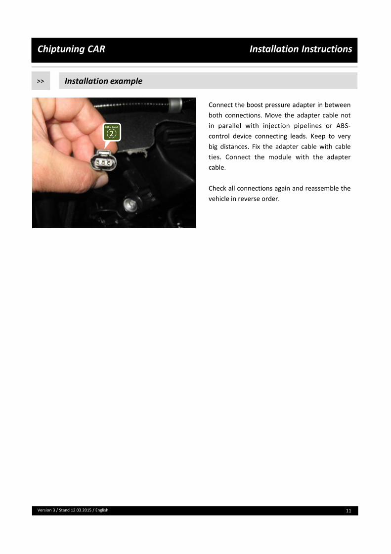
Connect the boost pressure adapter in between
both connections. Move the adapter cable not
in parallel with injection pipelines or ABS-
control device connecting leads. Keep to very
big distances. Fix the adapter cable with cable
ties. Connect the module with the adapter
cable.
Check all connections again and reassemble the
vehicle in reverse order.