chipsealing plant
TRANSCRIPT

C H A P T E RT E N Chipsealing Plant

Chap t e r 10 Ch i p s e a l i n g P l a n t
10.1 Introduction __________________________________________________________________________________________________________________379
10.2 Bitumen Distributors _____________________________________________________________________________________________________380
10.3 The Spraybar and its Operation ______________________________________________________________________________________381
10.3.1 The Spraybar ___________________________________________________________________________________________________________381
10.3.2 Spraybar Operation __________________________________________________________________________________________________384
10.3.3 Calibration of Bitumen Distributor ____________________________________________________________________________390
10.4 Pumping and Circulation Systems ____________________________________________________________________________________390
10.5 Instrumentation and Control __________________________________________________________________________________________394
10.5.1 The Dipstick ____________________________________________________________________________________________________________394
10.5.2 Tachometer _____________________________________________________________________________________________________________394
10.5.3 Binder Pressure Gauge _____________________________________________________________________________________________395
10.5.4 Distributor Speed Control ________________________________________________________________________________________395
10.5.5 Temperature Measurement _______________________________________________________________________________________395
10.5.6 Strainer Maintenance ________________________________________________________________________________________________396
10.6 Controlling the Binder Application Rate___________________________________________________________________________396
10.6.1 Total Binder Output Rate__________________________________________________________________________________________396
10.6.2 Pump Output___________________________________________________________________________________________________________397
10.6.3 Spray Control Systems______________________________________________________________________________________________398
10.7 Heating Systems_____________________________________________________________________________________________________________399
10.7.1 Safety Requirements _________________________________________________________________________________________________399
10.7.2 Insulation_________________________________________________________________________________________________________________399
10.7.3 Types of Heating Equipment ______________________________________________________________________________________400
10.8 Hazards of Plant Operations ___________________________________________________________________________________________400
10.8.1 Hazards of Blending Binder _______________________________________________________________________________________400
10.8.2 Hazards of Transferring Binder___________________________________________________________________________________401
10.9 Other Chipsealing Plant__________________________________________________________________________________________________402
10.9.1 Trucks for Chipsealing ______________________________________________________________________________________________402
10.9.2 Chip Spreaders ________________________________________________________________________________________________________402
10.9.3 Calibration of Chip Spreading Plant____________________________________________________________________________405
10.9.4 Rollers_____________________________________________________________________________________________________________________407
10.9.5 Brooms ___________________________________________________________________________________________________________________409
10.10 References ____________________________________________________________________________________________________________________413
Previous page: Placing chips using a self-propelled chip spreader. Note the receiving hopper at the rear beingfed with chip from the truck. After chip is spread, the fresh seal is compacted by the roller on the right.
Photo courtesy of Lindsay Roundhill, Opus

10
379C h i p s e a l i n g i n N e w Z e a l a n d
Figure 10-1 A sprayer in operation showing the spray fans. Note the different shape of the fan comingfrom the end nozzle. Photo courtesy of Lindsay Roundhill, Opus
Chapter 10 Chipsealing Plant
10 . 1 I n t r o du c t i o nConstruction equipment plays a key role in the success or otherwise of a safe chipseal. The
need for safety has never been higher because traffic loadings increase in intensity every
year in numbers, speed, weight and power. This means the margins for error in chipsealing
design and construction have narrowed greatly and, in order to construct a safe chipseal
successfully, correct operation of the complex specialised sealing plant is vital.
Sealing is a highly mechanised mobile operation (Figure 10-1). A single well-orchestrated
chipsealing crew can use in excess of 70,000 litres of bitumen in a day, and lay up to
50,000 m2 of seal per day (between 2.5 and 8 km, depending on road width).
To maximise these daily outputs, not only must each machine meet the performance
specifications required, but also it must be able to do its job without delaying the plant
used for the rest of the sealing operation.
Successful sealing demands the delivery of the exact quantities of binder, precisely and
evenly spread. A good distributor is necessary but is not enough on its own. It must be
operated by skilled operators who fully understand the principles and requirements of
spraying bitumen.

10
380 C h i p s e a l i n g i n N e w Z e a l a n d
1 0 . 2 B i t umen D i s t r i b u t o r sBitumen sprayers are traditionally known as bitumen distributors (even though they
usually carry binders). They are built specifically for the purpose of spreading or distributing
bituminous binders evenly across the road surface at the desired application rate. They
comprise a truck on which is mounted:
• an insulated tank;
• heating equipment;
• pump and circulating system;
• hand-spray lance and/or fully circulating spraybar, fitted with multiple nozzles
mounted on the rear of the unit;
• control system.
Small truck-mounted maintenance distributors with capacities usually under 2,000 litres
are used for sealing smaller areas such as maintenance patches.
Distributors typically ranging in capacity from 2,000 to 16,000 litres capacity are used
for large-scale sealing.
Given the right conditions, a typical 16,000 litre bitumen distributor is capable of
spraying out its load in under 20 minutes and can spray up to 70,000 litres per day,
provided all other sealing plant and operations can operate at a comparable rate and
support the efficient operation of this machine.
Bitumen Distributor Certificate of Compliance
The specification for performance of bitumen distributors is BCA E/2 (1992 or latest
version). This covers legal, safety and performance requirements, and includes a rigorous
annual safety inspection and a performance test.
The Certificate of Compliance with BCA E/2 is mandatory for bitumen distributors in
use on New Zealand state highways.
A Quality Assurance (QA) Manual should be developed for each distributor and always
kept with it. The QA Manual contains various useful documents including a diagram
showing how the outer spray fans should overlap the previous spray run. The QA Manual
also includes a Spray Application Rate Chart (spray chart) supplied at the time of
manufacture, which is checked annually as part of the BCA E/2 tests.
Allowing the contractor to begin expensive sealing operations without requiring evidence
of this certificate is most unwise.
10
381C h i p s e a l i n g i n N e w Z e a l a n d
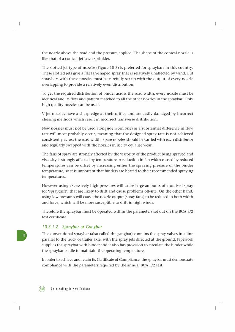
Figure 10-3 The slotted nozzle is the most commonly used type in New Zealand. It is shown in elevation(top left), and a plan view (bottom left), with a sectional elevation along section A-A of the nozzle (topright), and a plan view (bottom right).
A
A
Cross section through A-A
A A
Cross section through A-A
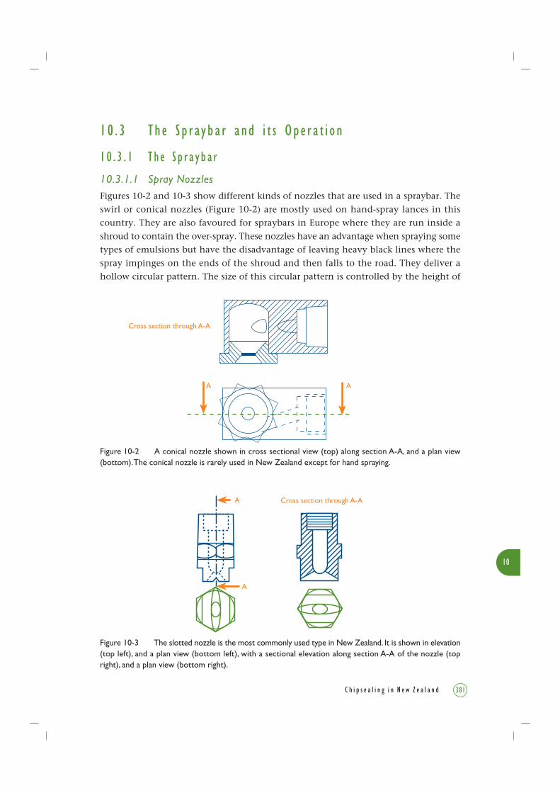
Figure 10-2 A conical nozzle shown in cross sectional view (top) along section A-A, and a plan view(bottom). The conical nozzle is rarely used in New Zealand except for hand spraying.
10 . 3 Th e S p r ay b a r and i t s Ope r a t i o n
10 . 3 . 1 T h e S p r a y b a r
10.3.1.1 Spray NozzlesFigures 10-2 and 10-3 show different kinds of nozzles that are used in a spraybar. The
swirl or conical nozzles (Figure 10-2) are mostly used on hand-spray lances in this
country. They are also favoured for spraybars in Europe where they are run inside a
shroud to contain the over-spray. These nozzles have an advantage when spraying some
types of emulsions but have the disadvantage of leaving heavy black lines where the
spray impinges on the ends of the shroud and then falls to the road. They deliver a
hollow circular pattern. The size of this circular pattern is controlled by the height of
10
382 C h i p s e a l i n g i n N e w Z e a l a n d
the nozzle above the road and the pressure applied. The shape of the conical nozzle is
like that of a conical jet lawn sprinkler.
The slotted jet-type of nozz1e (Figure 10-3) is preferred for spraybars in this country.
These slotted jets give a flat fan-shaped spray that is relatively unaffected by wind. But
spraybars with these nozzles must be carefully set up with the output of every nozzle
overlapping to provide a relatively even distribution.
To get the required distribution of binder across the road width, every nozzle must be
identical and its flow and pattern matched to all the other nozzles in the spraybar. Only
high quality nozzles can be used.
V-jet nozzles have a sharp edge at their orifice and are easily damaged by incorrect
clearing methods which result in incorrect transverse distribution.
New nozzles must not be used alongside worn ones as a substantial difference in flow
rate will most probably occur, meaning that the designed spray rate is not achieved
consistently across the road width. Spare nozzles should be carried with each distributor
and regularly swapped with the nozzles in use to equalise wear.
The fans of spray are strongly affected by the viscosity of the product being sprayed and
viscosity is strongly affected by temperature. A reduction in fan width caused by reduced
temperatures can be offset by increasing either the spraying pressure or the binder
temperature, so it is important that binders are heated to their recommended spraying
temperatures.
However using excessively high pressures will cause large amounts of atomised spray
(or ‘spraydrift’) that are likely to drift and cause problems off-site. On the other hand,
using low pressures will cause the nozzle output (spray fans) to be reduced in both width
and force, which will be more susceptible to drift in high winds.
Therefore the spraybar must be operated within the parameters set out on the BCA E/2
test certificate.
10.3.1.2 Spraybar or GangbarThe conventional spraybar (also called the gangbar) contains the spray valves in a line
parallel to the truck or trailer axle, with the spray jets directed at the ground. Pipework
supplies the spraybar with binder and it also has provision to circulate the binder while
the spraybar is idle to maintain the operating temperature.
In order to achieve and retain its Certificate of Compliance, the spraybar must demonstrate
compliance with the parameters required by the annual BCA E/2 test.

10
383C h i p s e a l i n g i n N e w Z e a l a n d
10.3.1.3 Spraybar Types
Each nozzle has a valve which is opened simultaneously by an actuating linkage. Individual
nozzles may be selected and closed off to set the spray width before the spray run.
Many spraybars are equipped with some (or all) remotely controlled individual valves.
This allows the operator to alter the spray width during the spray runs, and a tapering
road can be sprayed in a single pass of the distributor.
Control systems with capacity for data logging must compensate for these changes,
otherwise it will appear that a greater or lesser distance has been covered by a known
quantity of binder, and calculations of actual binder application rate will be affected.
Leading technology uses telescopic spraybars incorporating variable application capability.
This allows the width of the spray and spraybar to be altered without the spraybar
overhanging the edge of the road, and also allows the application rate to be altered
across the spraybar while the spraying operation is in progress.
Figure 10-4 Spray fans overlap to give triple coverage of binder on the road.
SIGNIFICANT WIDTH
EFFECTIVE WIDTH
SPRAYBAR
100 mm
Proper nozzle angle setting
SPRAYBAR AXIS
NOZZLE ANGLE SETTING
Triple CoverageDouble CoverageSingle Coverage
end taper
10
384 C h i p s e a l i n g i n N e w Z e a l a n d
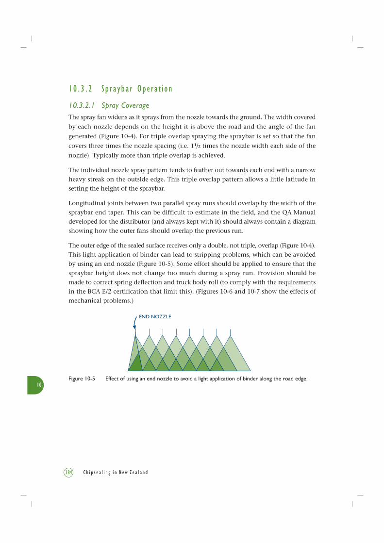
Figure 10-5 Effect of using an end nozzle to avoid a light application of binder along the road edge.
END NOZZLE
1 0 . 3 . 2 S p r a y b a r Ope r a t i o n
10.3.2.1 Spray Coverage
The spray fan widens as it sprays from the nozzle towards the ground. The width covered
by each nozzle depends on the height it is above the road and the angle of the fan
generated (Figure 10-4). For triple overlap spraying the spraybar is set so that the fan
covers three times the nozzle spacing (i.e. 11/2 times the nozzle width each side of the
nozzle). Typically more than triple overlap is achieved.
The individual nozzle spray pattern tends to feather out towards each end with a narrow
heavy streak on the outside edge. This triple overlap pattern allows a little latitude in
setting the height of the spraybar.
Longitudinal joints between two parallel spray runs should overlap by the width of the
spraybar end taper. This can be difficult to estimate in the field, and the QA Manual
developed for the distributor (and always kept with it) should always contain a diagram
showing how the outer fans should overlap the previous run.
The outer edge of the sealed surface receives only a double, not triple, overlap (Figure 10-4).
This light application of binder can lead to stripping problems, which can be avoided
by using an end nozzle (Figure 10-5). Some effort should be applied to ensure that the
spraybar height does not change too much during a spray run. Provision should be
made to correct spring deflection and truck body roll (to comply with the requirements
in the BCA E/2 certification that limit this). (Figures 10-6 and 10-7 show the effects of
mechanical problems.)

10
385C h i p s e a l i n g i n N e w Z e a l a n d
A gauge should be carried so that the nozzle height can be checked regularly. Another
gauge should be provided to ensure that the slot in a nozzle is set at an angle that prevents
the fan from interfering with the adjacent fan. The jet angle is generally set in the range
of 15° to 30° to the centre line of the bar (with all nozzles set to an identical angle).
Distributor operators must check the nozzle angles whenever a nozzle is changed, using
the correct angle-setting gauge (Figure 10-8).
Figure 10-6 When just one nozzle is blocked, three overlaps are receiving reduced binder application,leading to streaking and potential chip loss.
2
3
4
Blocked
Figure 10-7 Tilting of the spraybar caused by soft suspension. Photo courtesy of DCS Penny Ltd

10
386 C h i p s e a l i n g i n N e w Z e a l a n d
In circulating mode the binder is pumped from the tank along all parts of the spraybar
and back to the tank to heat the valves, nozzle and pipework to spraying temperature.
Circulation takes about 10 to 20 minutes, depending on the weather, and spraying must
not start before the spraybar is up to operating temperature. Some modern sprayers
monitor pipework temperature and do not allow spraying to commence until minimum
temperature is achieved.
In spraying mode, the spraybar on/off control simultaneously sets the spraying pressure,
closes the return to the tank, and opens the nozzle valves. The binder is fed to the bar
at several points along it to minimise pressure variations (Figures 10-13 and 10-14).
10.3.2.2 Spraybar ControlMost modern distributors incorporate electronic systems to control the binder application
rate. This may not be true on small maintenance sprayers and older machines.
From the driver’s seat the operator should be able to set and adjust the following
during spraying:
• application rate;
• spray width (number of nozzles);
• spraybar lateral position relative to the truck.
It can also be useful to be able to:
• lower and raise the spraybar bodily;
• lower and raise or extend the ends of the spraybar;
• raise or lower either side of the spraybar to accommodate changes in road undulations
or truck body roll.
10.3.2.3 Hazards with SpraybarsApart from the usual dangers involved with traffic control where trucks are operating
among people, traffic and other machinery, bitumen sprayers present several unique
hazards.
Figure 10-8 Nozzles are adjusted by appropriate gauges (kept near the spraybar) for correcting theirspacings and angles to ensure fans do not intersect.
3 LAP SPRAYING
NOZZLE SETTING SPANNER

10
387C h i p s e a l i n g i n N e w Z e a l a n d
Figure 10-9 A bitumen distributor with an old-style lever-operated spraybar.Photo courtesy of John Matthews, Technix Group Ltd
1 NZ PBCA (NZ Pavement & Bitumen Contractors’ Association) is now Roading New Zealand, as from26/06/2004. However COP BCA 9904 was published in 2000 by the then NZ PBCA, so keeps its originalpublication number.
The spraybar is always potentially dangerous and should be under the control of an
experienced operator who is fully conversant with the dangers of hot binder when it
is under pressure.
Spraybar operators are not to stand on the platform at the rear of the truck, where they
are exposed to considerable hazards. To avoid this unsafe practice (which was necessary
for old-style lever-operated spraybars, see Figures 1-6 and 10-9) alternative control systems
have been available for some time.
Care should be taken at first start-up in case a slug of cold binder has blocked the spraybar
or transfer hose.
Procedures for preventing and dealing with these hazards are given in detail in Chapters 5
and 6 of the Roading NZ Code of Practice BCA 9904 (NZ PBCA 2000)1.
Procedures for controlling traffic while spraying are given in Transit NZ’s Code of Practice
for Temporary Traffic Management (COPTTM, Transit NZ 2004). It provides details for the
set-out of a site during these operations. More information is in Chapter 11 of this book.

10
388 C h i p s e a l i n g i n N e w Z e a l a n d
Figure 10-10 Use paper to make an accurate start line when starting a spray run.Photo courtesy of Les McKenzie, Opus
Figure 10-11 Hand spraying an extra width near a side road.Photo courtesy of Fraser Ellis, Fulton Hogan Ltd

10
389C h i p s e a l i n g i n N e w Z e a l a n d
Figure 10-12 Calibration of bitumen distributor. Photo courtesy of Bryan Pidwerbesky, Fulton Hogan Ltd
10.3.2.4 Spray Start and FinishThe transverse joints between successive spray runs can be very obvious unless the joint
is made accurately. To make an accurate start, runs must always be started and stopped
on paper laid transversely across the surface at both the start and finish (Figure 10-10).
When using lighter application rates it will be necessary to back over the paper to ensure
the sprayer has achieved the required forward speed before the spray start. Adequately
preheating the spraybar by circulation is also vital in establishing a sharp clean start for
the spray run.
10.3.2.5 Hand SprayingMost bitumen distributors carry a hand-spray lance for sealing odd-shaped and inaccessible
areas that are not practical to spray with the spraybar, e.g. in corners, around posts, and
other restricted areas (Figure 10-11). As it requires a skilled operator, the amount of hand
spraying needs to be kept to an absolute minimum and should be avoided in wheelpaths
wherever possible. Using telescopic spraybars dramatically reduces the amount of hand
spraying required.
Tests on carpet tiles have proved that even an experienced hand-spray lance operator
does not achieve a satisfactory application rate over the entire area, so a good hand-
spray job is poor compared to that obtained with a spraybar.
10
390 C h i p s e a l i n g i n N e w Z e a l a n d
1 0 . 3 . 3 C a l i b r a t i o n o f B i t umen D i s t r i b u t o r
All bitumen distributors are supplied with a Spray Application Rate Chart (spray chart)
at the time of manufacture which is specific to that distributor. Distributors produced
by different manufacturers will have different characteristics, such as nozzle output in
litres/minute on which the spray chart is established. These charts are always carried
with the distributor. They are checked annually by laboratory personnel who conduct
the BCA E/2 tests. These spray charts are mandatory for all distributors. Figure 10-12
shows the method of calibrating the spray rate onto the road surface.
10 . 4 Pump i n g and C i r c u l a t i o n S y s t em sThree types of sprayer control systems are in common use on distributors in New Zealand.
In BCA E/2, they are designated Types A, B and C.
Type A system (Figure 10-13): in these systems the spraybar pressure is held constant
and the application rate is achieved by precisely controlling the speed of the vehicle.
The binder pressure in the spraybar is controlled by a simple pressure control valve.
During spraying, excess binder must continue to be bled off through the control valve.
To date, type A sprayers have been found to be difficult to operate accurately because
of limitations in the accuracy of the bypass valve control, and limitations in precisely
measuring the pressure of a viscous, temperature-dependent binder.
Types B and C systems: in these systems all the binder passes through the spraybar
nozzles when the distributor is spraying (i.e. none is circulated back to the tank). A
pressure relief valve must be fitted in case of a spraybar blockage during spraying and
should be set at approximately twice the spraying pressure. Both B and C systems use
a metering binder pump.
In a Type B system the metering binder pump speed is precisely controlled to give
constant output per nozzle for the number of nozzles in use. The desired application
rate is achieved through precise control of the pump and precisely controlling the speed
of the vehicle.
Type C systems are hydraulically identical to type B systems. However, the metering
binder pump is driven at a speed proportional to the road speed of the vehicle by a
power take-off from the distributor’s motor or transmission. The vehicle needs to be
controlled to within ±5% of a predetermined road speed to achieve the desired binder
application rate.

10
Figure 10-13 Simplified Type A system of binder pump.
Pressure control valve
Tank
Return flow
PumpPressure guage
Spray Bar
Nozzle valvesNozzles
391C h i p s e a l i n g i n N e w Z e a l a n d
Pumps on type B and C systems should incorporate the following design aspects:
• Delivered binder application rate must have very little variation over the operating
speed range, i.e. output is proportional to speed. The typical gear pumps that are in
use work on the principle of a flow meter.
• Pumping action must be smooth as pulses could influence longitudinal spray pattern
at high road speeds.
• Pumps should be designed for hot binder.
• Changing the number of operating spray nozzles while in use requires the pump
output to be varied in proportion to the changes made.
Types A and B systems could be driven by an auxiliary diesel motor or an engine power
take-off. Either way, the pump must be able to be controlled at a constant rate regardless
of the truck speed.
Type C system pumps are always driven from a power take-off from the distributor’s
motor or transmission. The power take-off may therefore be mounted on the distributor
vehicle’s engine or transmission. Usually a hydrostatic transmission is used to transmit
the power from the take-off to the pump because it allows the speed ratio between the
take-off and pump shafts to be varied smoothly. Once it is set up for the number of
nozzles to be used on the spray run, the ratio remains fixed.
Figure 10-14 illustrates the schematic layout of a typical spraybar and the associated
pumping and circulating system when spraying.

10
Figure 10-14 Passage of binder in spraybar and tank when spraying. Courtesy of DCS Penny Ltd
1. Discharge Valve2. Filter3. Bitumen Pump4. Control Valve (Bar Spray, Hand Spray, Circulate)5. Spraybar Pressure Equilising Valve6. Bypass Valve to Tank7. Tank Return and Blend Pipe8. Pump-in and Pump-out valves and attachment for hand spray
Tank Shell
F
Gang bar, Nozzles not shown
5
43
2 7
1 8
6
FlushingValve
392 C h i p s e a l i n g i n N e w Z e a l a n d

10
393C h i p s e a l i n g i n N e w Z e a l a n d
Figure 10-15 Typical circulating system used in a binder distributor tank. Top diagram is a longitudinalcross section. Bottom diagram is an end elevation. Courtesy of DCS Penny Ltd
From Pump
To PumpVia Strainer
1/3 Pump Output
Return PipeRemoveable Access Plate
Flame Tubes Element Tubes
Figure 10-15 shows a longitudinal section of a typical circulating system used in a bindertank. The functions of the system are to:
• Fill the tank.
• Circulate the binder in the tank.
• Circulate the binder through the bar and tank.
• Transfer binder from tank to tank.
• Spray binder through the hand-spray lance or spraybar.
• Suck binder back into the tank to clear the hand-spray lance or spraybar.
• Flush the system. Incorporated in the pipe work is a facility for flushing oil through
the spraybar and pump after the system has been purged of binders, to ensure that
no blockages are caused by congealing residual binder.
A number of transient and permanent faults can affect the pump’s output per revolutionand hence affect the accuracy of binder outputs calculated from the pump revolutions.Some of these are:
• Wear or damage to the pump.• A faulty pressure relief valve: this could be caused by grit preventing the valve from
seating completely, or by reduced pressure in the valve-closing mechanism.• Blocked or partially blocked strainer: this is a fairly common fault.• Air entrainment in the binder: when the pump is operating at full speed, i.e. when
spraying to full width, air can be sucked in if the level of binder is too low over themain tank valve. This is more likely to occur if the last spray run is downhill.
10
394 C h i p s e a l i n g i n N e w Z e a l a n d
1 0 . 5 I n s t r umen t a t i o n and Con t r o lMany modern bitumen sprayers now monitor the performance of critical functions (i.e.of binder pressure, vehicle speed, temperature measurement, strainer maintenance) andgive a warning (often audible) if these functions are outside the acceptable parameters.
10 . 5 . 1 T h e D i p s t i c k
The dipstick is the main direct method of measuring the volume of material added toor sprayed from the tank. Modern systems may include direct electronic sensing ofbinder level.
Under the BCA E/2 procedure, dipsticks are calibrated to ±50 litres for tanks larger than2000 litres and ±20 litres for smaller tanks. Since the reading error is not proportionalto volume, readings over a full tank load are the most accurate. For this reason, asdiscussed below in Section 10.5.2, the dipstick is best used in conjunction with anaccumulating pump tachometer.
For example, it is essential to take check dipstick measurements (at least 3 per distributorload are recommended) with a tachometer reading. Readings at approximately full, halffull and before refilling are advised. If the two sets of measured quantities agree within
the dipstick reading tolerance given in the bitumen distributor’s QA Manual, the pump
revolution reading may be taken as the more accurate. However if the disparity is greater
than this, the system must be checked and the application rates for the affected spray
runs reported.
10 . 5 . 2 T a c home t e r
Accumulating pump tachometers are counters that record the cumulative number of
pump revolutions. They are fitted to many distributors.
The accuracy of the accumulating tachometers should be regularly checked against
the dipstick.
Many distributors now have electronic pump governors, in which case the tachometer
provides the means of checking and setting the pump governor for types A and B systems.
For type C systems, the tachometer provides an essential check of the setting of the
hydrostatic pump drive. The rpm of the pump needs to be checked against the spray
rate chart when the distributor is travelling at the speed indicated on the spray rate
chart. This is to ensure that the actual pump rpm at a given speed matches the spray
rate chart at that speed.
10
395C h i p s e a l i n g i n N e w Z e a l a n d
The number of revolutions recorded by an accumulating pump tachometer can be usedto calculate the binder sprayed in the run. This method can be more accurate than themeasured quantities by taking dipstick readings before and after the run, especially ifthe area that is sprayed is small. However, the tachometer readings should never berelied on as the sole measurement.
10 . 5 . 3 B i n d e r P r e s s u r e Gaug e
For a type A sprayer, the accuracy of the nozzle output depends on the accuracy withwhich the bar pressure is monitored and controlled. Output is proportional to the squareroot of pressure, and thus the maximum acceptable error in pressure gauge reading istwice the maximum allowable variation in total spray output.
For type A systems, BCA E/2 requires a 100-mm nominal diameter Industrial Gauge toNZS/BS 1780:1985 (SNZ 1985) standard, giving an accuracy of ±1%. For example, thebourdon tube-type gauge appears to be the most reliable and economical type capableof sufficient accuracy. For type B and C systems, a 50-mm nominal diameter gauge isrecommended as a means of checking system performance.
10 . 5 . 4 D i s t r i b u t o r S p e ed Con t r o l
BCA E/2 requires that the distributor’s speed control system must be able to control theaverage speed over a 100m length to within ±3%.
The traditional method for speed control was to use an industrial tachometer drivenfrom a fifth wheel. Because of the vulnerability of fifth wheels to damage, most moderndistributors use either a high accuracy engine tachometer, or a tachometer with a sensoron the transmission or on a wheel. It is necessary to ensure that the accuracy is notaffected because of changes to the rolling circumference of the vehicle tyres caused bytyre pressure variation, loading variation, build-up of dirt, bitumen and chip or wear.
A much more accurate approach is the use of an electronic vehicle speed governor. Accuracyof better than 0.5% over 100 m can be achieved. The driver is spared a difficult task andinstead can concentrate on driving the vehicle and monitoring the spraying system.
10 . 5 . 5 T empe r a t u r e Mea s u r emen t
BCA E/2 requires distributors to be equipped with two thermometers, accurate to ±5°Cover a temperature range of 20°C to 200°C for spraying cutback binders, or 0°C to 100°Cfor emulsion sprayers. The first thermometer must be mounted so that it gives an accuratereading of the binder passing to the pump. The second is mounted remote from thefirst and in a position to monitor the binder temperature when the tank heaters areoperated.

10
396 C h i p s e a l i n g i n N e w Z e a l a n d
Before spraying, the binder needs to be circulated until all material in the tank is properly
mixed and at a uniform temperature. This is indicated by the two thermometers agreeing
within their combined rated accuracy of ±10°C.
As the binder level falls during a spray operation, the second thermometer will eventually
become exposed to the vapour space and this may result in a low reading. This cause
should be obvious from dipstick readings.
10 . 5 . 6 S t r a i n e r Ma i n t e n an c e
The strainer provides essential protection for the whole spraying system, helping to
prevent damage and blockages to every part of the system. The strainer should be checked
for blockages regularly and cleaned as appropriate. At the same time it should be examined
for wear or damage that may allow damaging particles to get through.
A strainer may go for months without being even partially blocked and then become
hopelessly clogged from one load. The problem is that there is no way of knowing when
debris, that might have been dislodged in any number of intermediate tanks and pipes
on the binder’s journey from refinery to the distributor pump, will build up in the
strainer. Therefore the strainer needs to be checked at least daily to ensure ongoing good
performance of the distributor.
The recommendation is to check strainers after every use of the pump, at the end of the
day, and after every 15,000 litres sprayed, even if there is no obvious problem. If a heavy
deposit is found on a strainer, clean it before every spray run until the source of contamination
is known and no contamination is left in the system or upstream in the supply chain.
Failure to clean strainers can lead to blocked nozzles or low application rates.
10 . 6 Con t r o l l i n g t h e B i n d e r App l i c a t i o n Ra t e
10 . 6 . 1 To t a l B i n d e r Ou t pu t Ra t e
Because the output per nozzle is fixed, the binder application rate is controlled by the
distributor speed. The faster the distributor moves, the lower the rate. For all spray run
widths and application rates:
R = On
SV
where: R = application rate ( /m2)
On = output per nozzle ( /min)
S = spacing of nozzles (m) (generally 0.1 m)
V = speed of spraying vehicle (m/min)
10
397C h i p s e a l i n g i n N e w Z e a l a n d
Whatever the application rate, the total binder output rate is the total of the outputsof all nozzles operating.
P = On N
where: P = total binder output rate ( /min)N = number of nozzles operating
(This will have to be modified appropriately when end nozzles are in use if the endnozzle has a different size to the ordinary nozzles.)
Note that where a spraybar is fitted with electrically or pneumatically controlled nozzles,the switches must be inter-linked with the pumping system to ensure that the rate ofbinder delivery remains matched to the new spray width. Each distributor has a BCAE/2-approved spray chart applying to that particular distributor based on these principles.
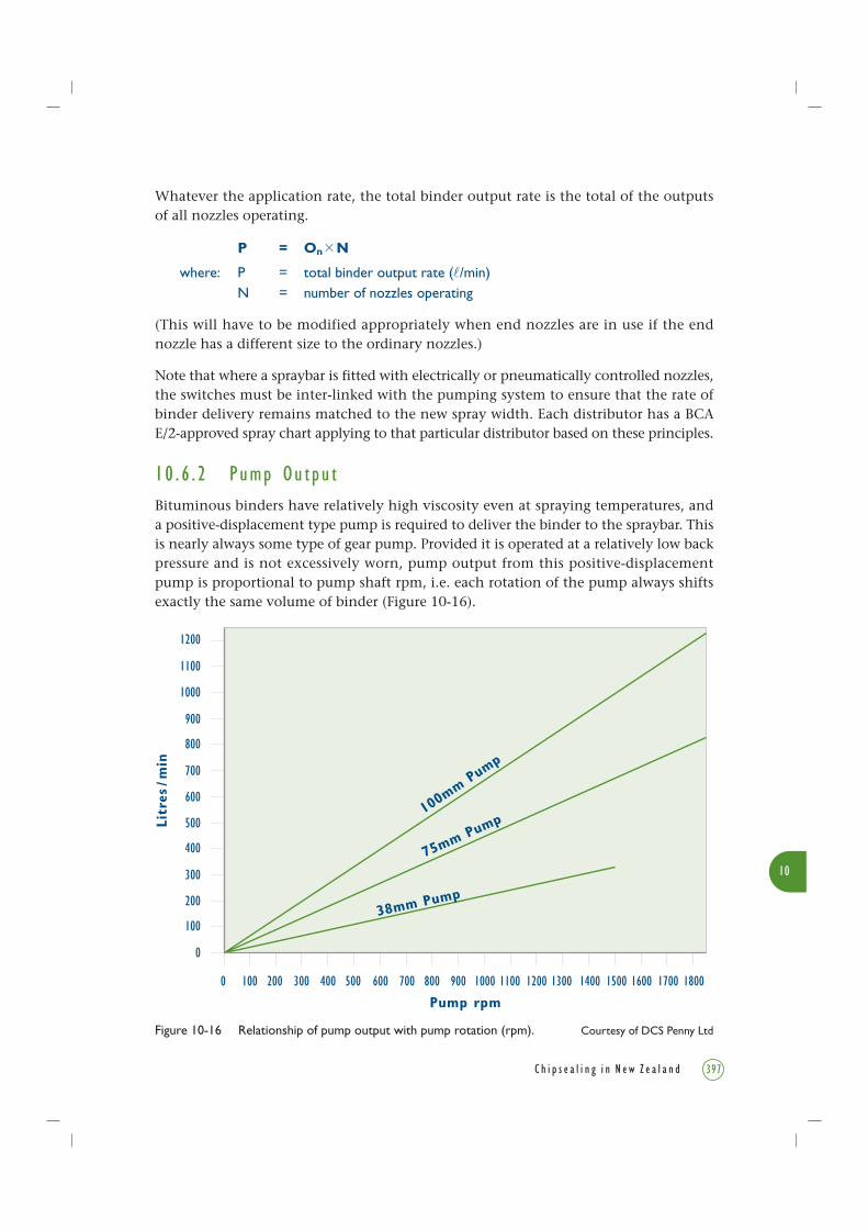
10 . 6 . 2 Pump Ou t pu tBituminous binders have relatively high viscosity even at spraying temperatures, anda positive-displacement type pump is required to deliver the binder to the spraybar. Thisis nearly always some type of gear pump. Provided it is operated at a relatively low backpressure and is not excessively worn, pump output from this positive-displacementpump is proportional to pump shaft rpm, i.e. each rotation of the pump always shiftsexactly the same volume of binder (Figure 10-16).
Figure 10-16 Relationship of pump output with pump rotation (rpm). Courtesy of DCS Penny Ltd
Litr
es/m
in
Pump rpm
1200
1100
1000
900
800
700
600
500
400
300
200
100
0
0 100 200 300 400 500 600 700 800 900 1000 1100 1200 1300 1400 1500 1600 1700
100m
m Pump
75mm Pump
38mm Pump
1800

10
398 C h i p s e a l i n g i n N e w Z e a l a n d
1 0 . 6 . 3 S p r ay Con t r o l S y s t em s
The three types of spray control systems in use on distributors in New Zealand are
described in Section 10.4.
Since the nozzle output depends on the pressure which is controlled by a simple valve
in the type A system (Figure 10-13), theoretically the pressure control valve makes the
bar output independent of pump speed. In practice, bar pressure depends also on viscous
and turbulent drag in the pipes between bar and valve and in the valve itself. Hence,
the binder viscosity and the rate of flow through the valve should be kept as constant
as possible to ensure constant bar pressure:
Pump Output = On N + fv
where: fv = constant value of flow-through valve
On = output per nozzle
N = number of nozzles operating
Before spraying, the pump speed governor is set to a level that is determined by the spray
width. This can be done directly by setting the pump rpm to a particular value as read
on the pump tachometer, or indirectly by adjusting the rpm until the pressure gauge
shows that the bar pressure is at a value that is appropriate for that width of spray. As
spraying starts the bar pressure generally changes, so during spraying the pressure must
be monitored to ensure that it is at the desired level to achieve the desired spray output.
Type B system pump speed is set to give exactly the correct output for the number of
nozzles in use:
r = pump rpm = f (P)
where: P = pump output= On N
For an unworn positive displacement pump:
r = On N
Or
where: Or = pump output per revolution
On = output per nozzle
N = number of nozzles operating
The application rate is controlled by precise control of the distributor speed, as is the
case for type A.
The above relationships are also true for the type C system which is hydraulically
identical to the type B system.

10
399C h i p s e a l i n g i n N e w Z e a l a n d
1 0 . 7 Hea t i n g S y s t em s
10 . 7 . 1 S a f e t y R equ i r emen t s
All binder heating systems must comply with the latest BCA E/2 and COP BCA 9904
which contain requirements and tests for heating capacity and tank insulation performance.
Bitumen distributors (Figure 10-17) and bitumen tanker vehicles used to transport binder
to the distributor in the field must comply with the heating safety requirement of the
COP BCA 9904 (Chapter 6.7, NZ PBCA 2000). This is a requirement of the BCA E/2,
audited at the annual and triennial inspections.
The heating of binder is potentially hazardous. It must always be carried out in accordance
with BCA 9904.
10 . 7 . 2 I n s u l a t i o n
The better insulated the distributor tank and the circulating pipework, the less re-heating
will be required. This is desirable on safety and energy conservation grounds and will
also reduce damage to the binder itself.
Figure 10-17 A bitumen distributor in action. Photo courtesy of Fraser Ellis, Fulton Hogan Ltd

10
400 C h i p s e a l i n g i n N e w Z e a l a n d
1 0 . 7 . 3 Ty p e s o f Hea t i n g Equ i pmen t
10.7.3.1 Flame Tube Heaters
These heaters are used to rapidly heat binder to spraying temperature. They consist of
a burner mounted at the end of the tank firing into a steel U- or Z-shaped tube (the
flame tube) along the bottom inside the tank (Figure 10-15). The exhaust flue is outside
the tank adjacent to the burner. These burners should only be run while the tanker is
stationary, standing on level ground, and with the tank content above the level on the
dipstick that ensures 200 mm of cover over the top surface of the heating tubes.
Control systems range from manual control to fully automatic with thermostatic control
and flame-out protection devices.
If the tank temperature drops too low so that the product is no longer liquid, special
action must be taken to avoid spot heating the product while trying to make it liquid
again. Lighting the burner in short bursts may be necessary. Procedures must be developed
for heating from solid to avoid excessive stress on the tank structure caused by expansion
of the binder.
10.7.3.2 Electrical Heating
Thermostatically controlled electric elements fitted to spray tankers are normally used
for maintaining temperature, or for overnight heating at a depot. They should only be
used when the machine is standing on level ground and when the tank contents are
above the safe heating level indicated on the dipstick. This ensures 200 mm of cover
over the top surface of the heating tubes.
The blending of binder is potentially hazardous. It must always be carried out in
accordance with the Roading NZ Code of Practice, Safe Handling of Bituminous
Materials used in Roading (NZ PBCA 2000, BCA 9904) and other manuals referred
to in Chapter 2 of this book (e.g. NZ PBCA 2001).
10 . 8 Ha z a r d s o f P l a n t Ope r a t i o n s
10 . 8 . 1 Ha z a r d s o f B l e nd i n g B i n d e r
Flammable additives should never be introduced through the tank hatch on to the
surface of hot binder. They should always be introduced by carefully sucking them in
through the distributor’s pump-in valve or siphon.
10
401C h i p s e a l i n g i n N e w Z e a l a n d
The safest and most effective method of adding cutters, fluxes and other additives into
a distributor is in-line blending. In this process, the additives are fed simultaneously
and in the correct proportions to the suction line of the distributor pump. Drawing the
additive into the suction line when transferring from the supply tanker into the distributor
is one method. Some distributors are equipped to allow in-line blending directly by
sucking in additive while the pump is circulating. Such activities should be completed
at the mixing plant and not on-site.
For the system to be effective as a blending unit, the binder pump should be operating
at maximum output. This ensures that the flow rate of binder provides adequate
turbulence inside the tank.
Water contamination of the product to be blended presents an extremely dangerous
situation. See Chapter 6.6 and Appendix 11 of BCA 9904, for precautions against the
presence of water, operating and safety procedures to cope with water in hot bitumen.
10 . 8 . 2 Ha z a r d s o f Tr a n s f e r r i n g B i n d e r
The loading of binder is potentially hazardous. It must always be carried out in accordance
with Chapter 6 in BCA 9904, and BCA E/2.
When transferring binder, wherever possible, suck it through the transfer hose or, failing
this, ensure that the pressure setting on the pumping unit is well below the pressure
rating of the transfer hose. Start pumping slowly and allow the system to heat. The
operator should be in a position, without endangering himself, to take remedial action
at all times should an emergency arise.
Personal protective equipment (PPE) comprising overalls, boots, balaclava and face mask
must be worn when transferring product. All pipework, equipment, and surfaces should
be treated as being very hot.
Protective clothing and PPE must be worn by all those working around the machine.
High visibility garments are essential for all sealing crew members.
An impact that ruptures the spraybar is very dangerous, so the bar should be kept in the
parked position, i.e. telescoped together or folded up, depending on design, if it is not
in use. Staff must be alert to the hazards of working amongst traffic, and understand
how to control these hazards. COPTTM (Transit NZ 2004) explains how to work safely
amongst traffic, and BCA 9904 gives details for safe transfer procedures.

10
402 C h i p s e a l i n g i n N e w Z e a l a n d
1 0 . 9 O t h e r Ch i p s e a l i n g P l a n t
10 . 9 . 1 Tr u c k s f o r Ch i p s e a l i n g
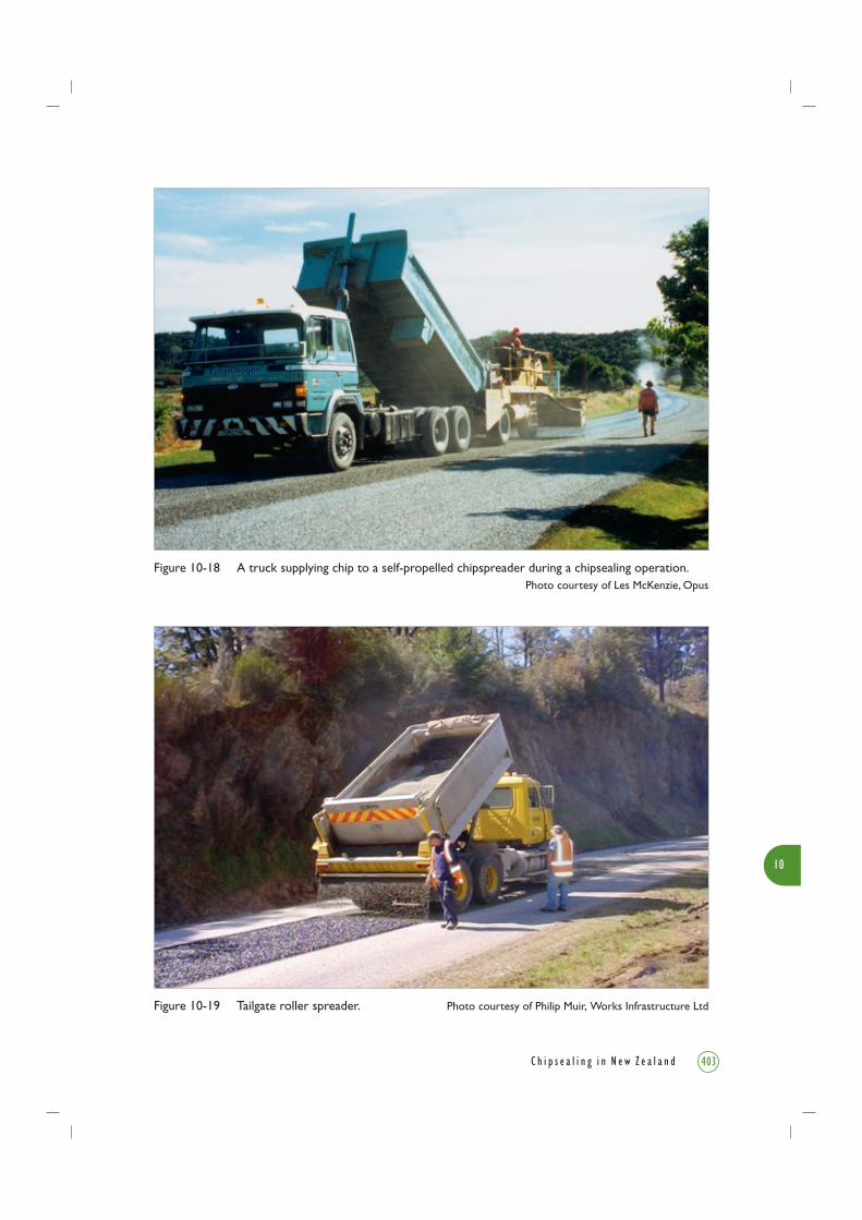
Commercially available trucks (Figure 10-18) selected for use in chipsealing operations
require appropriately powerful engine torque and low gear ratio specifications to suit
the relatively low road speeds and the situations of working on hilly sloping roads while
spraying. Some contractors fit left-hand drives to their vehicles which give the driver
greater ease of control when operating along with the flow of the traffic.
Axle configurations vary depending on the gross laden weight. The most favoured
combination consists of a tandem rear axle and single steering axle. Care is needed when
turning this combination as the tandem axle tends to badly scuff a new seal.
10 . 9 . 2 Ch i p S p r e ad e r s
Spreaders used in New Zealand are devices either attached to a truck tailgate or self-
propelled machines.
Traditionally, tailgate spreaders range from the simple fan-tail and box types to the more
sophisticated hydraulically operated roller spreader. Only the latter type is capable of
consistently providing the necessary control of evenness and application rate.
Self-propelled chip spreaders receive chip from trucks and apply it to the sprayed surface
in a controlled way. These machines have the ability to spread chip in much wider passes
than tailgate spreaders, and to match the width of the spraybars.
10.9.2.1 Truck-Mounted Roller SpreaderIn the tailgate roller spreader illustrated in Figure 10-19, chips are gravity discharged
from the truck tray through an adjustable gate and onto a rotating roller. The peripheral
speed of the roller and degree of gate opening will determine the rate at which the chips
will flow through to the roller and onto the ground.
Theoretically, if the gate opening is sufficient to produce an even single layer of chip
on to the roller, and its peripheral speed matches the road speed of the truck, a single
layer of chip would be spread on to the road surface.
In practice however, the peripheral speed of the roller is controlled at a lower road speed
than that of the truck. This enables a wider gate opening to be used, resulting in a freer
flow of chips onto the roller and better control of the application rate.
Some manufacturers may claim that roller spreaders will perform consistently, irrespective
of truck speed, though many operators have found that this is only partially correct.
10
403C h i p s e a l i n g i n N e w Z e a l a n d
Figure 10-19 Tailgate roller spreader. Photo courtesy of Philip Muir, Works Infrastructure Ltd
Figure 10-18 A truck supplying chip to a self-propelled chipspreader during a chipsealing operation.Photo courtesy of Les McKenzie, Opus

10
404 C h i p s e a l i n g i n N e w Z e a l a n d
Width Variation
Modern spreaders are fitted with pneumatically operated cut-off plates. These can be
activated from a control station on the side of the truck where the operator can be in
full view of the driver. The older method of varying the width of spread by the operator
physically inserting cut-off plates was very hazardous and is now not acceptable.
Control of Longitudinal Chip Spread
In some cases, the hydraulic drive for the roller-spreader drum is driven from a source that
does not vary in proportion to the truck speed, e.g. off the truck hoist hydraulic system.
In such cases the speed of the truck must be absolutely constant and correct for the entire
spread run. If the roller is driven from a hydraulic system driven from engine or transmission,
the chip spread rate is not so sensitive to a change in operating speed.
However it is still highly desirable to operate the truck at a reasonably constant speed.
This is no easy task considering the driver is operating in reverse and has the added
problems of poor vision, overhanging wires, trees, etc. A number of contractors have
taken the practical step of fitting pre-set automatic truck speed controllers, which greatly
improves the spreading operation.
An inconsistent flow rate of chips from the tray onto the roller is often caused by the
spreader mismatching the type of tray fitted on the truck. Variations in the hoist angle
can also cause inconsistent spreading.
Transverse Chip Distribution
The roller spreader is usually wider than the truck as this is essential for manoeuvrability.
The hopper and the hopper tray connection must be designed so that the flow of chips
from the tray out to the ends of the spreader is as good as that to the centre section
immediately behind the tray. If this is not done, the spread rate at the edges of the
spread will be too light.
On very tight corners, the end of the roller spreader on the inside of the bend has to
cover less ground than the outside end. This means that it is moving more slowly than
the truck, while the other end must move more quickly. The result is slightly too much
chip on the inside of the bend and too little on the outside. It is much better to correct
this by drag or hand brooming than to increase the chip spread rate.
10.9.2.2 Self-Propelled Chip SpreadersThese self-propelled motorised units are driven forward, allowing the operator to have
a full view of the spreading operation (Figure 10-20). They have a receiving hopper at
the rear for the chips from the supply trucks, and chips are transported to the spreading
bin at the front. This bin is fitted with a feed gate and roller system which controls the
spread of the chips relative to the speed of the machine. The gates are also used for
varying the spread width.

10
405C h i p s e a l i n g i n N e w Z e a l a n d
Some spreaders are designed to tow the feeder truck so the truck operator does not have
to match speeds with the spreader during the spread run. A special hitch attachment
allows for a change of trucks without having to stop during a chip-spreading run.
The disadvantages of a self-propelled chip spreader are cost, manoeuvrability is difficult
in very tight areas, and transportation as they need to be trucked to the site.
The advantages of the self-propelled spreader are the quick turn-round of the chip trucks,
considerably greater spreading width and speed, and better control, because only one
machine has to be set-up and controlled.
10 . 9 . 3 C a l i b r a t i o n o f Ch i p S p r e ad i n g P l a n t
Chapters 9 and 11 describe the importance of an accurate and even spread of sealing
chip to achieve a top quality job. In New Zealand, a lack of control of chip application
rates has been observed even though chip spreaders are available that are fully capable
of being calibrated to produce a consistent application and uniform spread rate of chips.
The wasteful and damaging variation and general over-application of chip is considered
to be attributable to:
• Lack of operator training: many supervisors and foremen have different interpretations
on what constitutes a correct application rate of chips;
Figure 10-20 Self-propelled chip spreader. Photo courtesy of Lindsay Roundhill, Opus

10
406 C h i p s e a l i n g i n N e w Z e a l a n d
• Spreaders are not being tested and calibrated; and
• Drag brooming is not commonly used.
Contractors’ QA systems should have a regular programme of calibration, adjustment
and operator training in accordance with the spreader manufacturer’s instructions and
operating manuals.
The spreaders have to be carefully adjusted to the correct settings for every change of
chip ALD, chip stockpile, and design application rate.
Verification of chip application rates can be determined by carefully measuring the area
covered by each truck load or by laying a section of cloth or building paper on the
pavement, not less than 1m2 in area, and passing the spreader over it (Figure 10-21).
Aggregate collected can then be weighed and this will determine the weight per square
metre of chips being spread using the equations given in Section 11.3.7.
Figure 10-21 Procedure for calibrating chip spreading on paper.Photo courtesy of Bryan Pidwerbesky, Fulton Hogan Ltd
10
407C h i p s e a l i n g i n N e w Z e a l a n d
1 0 . 9 . 4 Ro l l e r s
The function of the roller is to ensure embedment of the chip into the binder and to
provide a uniform mosaic of chip. Smooth steel-wheeled rollers are not often used on
chipseal work because of the risks of breaking and crushing the chip, particularly when
using softer aggregates and where uneven surfaces result in variable contact pressure.
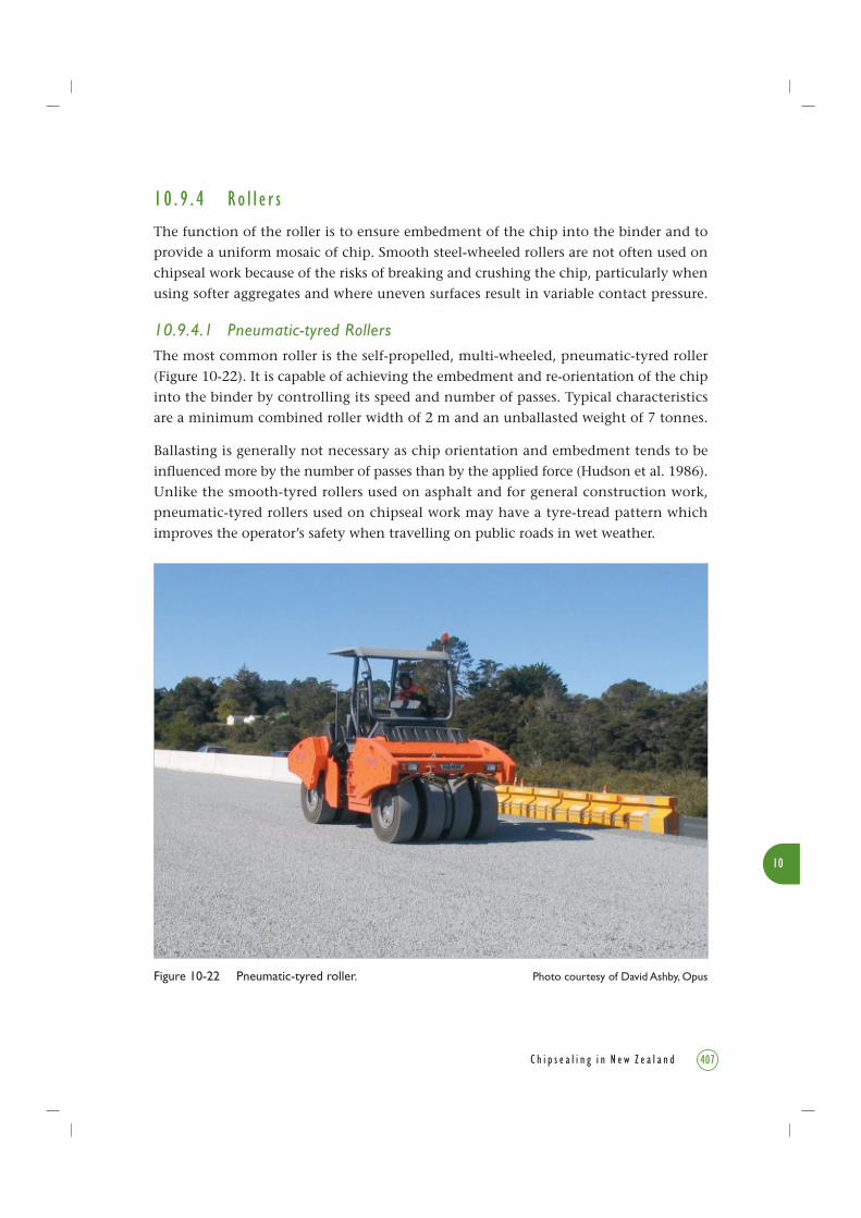
10.9.4.1 Pneumatic-tyred RollersThe most common roller is the self-propelled, multi-wheeled, pneumatic-tyred roller
(Figure 10-22). It is capable of achieving the embedment and re-orientation of the chip
into the binder by controlling its speed and number of passes. Typical characteristics
are a minimum combined roller width of 2 m and an unballasted weight of 7 tonnes.
Ballasting is generally not necessary as chip orientation and embedment tends to be
influenced more by the number of passes than by the applied force (Hudson et al. 1986).
Unlike the smooth-tyred rollers used on asphalt and for general construction work,
pneumatic-tyred rollers used on chipseal work may have a tyre-tread pattern which
improves the operator’s safety when travelling on public roads in wet weather.
Figure 10-22 Pneumatic-tyred roller. Photo courtesy of David Ashby, Opus

10
408 C h i p s e a l i n g i n N e w Z e a l a n d
These rollers are operated at much higher speeds on sealing operations than would be
normal for asphalt, pavement or subgrade compaction. The first pass is at 5-10 km/h
to bed the chip in. Once the first full coverage of the area is complete, a higher speed
of 15-29 km/h is more effective for re-orienting the chip and also increases the number
of passes in a given time. Drive systems need to be capable of these speeds.
10.9.4.2 Rubber-coated Vibrating Drum RollersThe rubber-coated vibrating drum roller is specifically designed for sealing operations.
The rubber coating is provided to reduce the crushing associated with steel-wheeled rollers
(Figure 10-23) but still provide the high contact pressure that assists with chip embedment.
Overall width and speed is less than that for pneumatic-tyred rollers but this type of roller
has been observed to be very effective in re-orienting chip (Sheppard & Petrie 1989, 1990).
If the pavement is rutted, the drum will tend to bridge the wheelpaths which will then
not be well compacted. This can be allowed for, to some extent, if the roller has pneumatic
rear wheels which are used to roll the wheelpaths. Note that the wheelpaths need some
compaction but it is relatively less than for other areas as wheelpaths will be well
compacted by traffic later.
Figure 10-23 A steel-wheeled roller. Photo courtesy of Julien van Dyk, The Isaac Construction Co. Ltd

10
409C h i p s e a l i n g i n N e w Z e a l a n d
10.9.4.3 Combination RollersThe combination roller combines a rubber-coated steel vibrating drum on one axle with
a single row of pneumatic tyres on the second (rear) axle (Figure 10-24). This is intended
to provide the benefits of both the above forms of compaction in the embedment and
re-orientation of chips.
10 . 9 . 5 B r o oms
Brooms used in chipsealing work have three separate functions:
• Removal of dust and loose foreign material before spraying operations (sweeping);
• Uniformly distributing inconsistently spread chips (drag brooming);
• Removal of loose chip from completed work (sweeping).
In dry conditions, sweeping may cause considerable dust nuisance. This is controlled
with water applied by water trucks.
Figure 10-24 The two axles of a combination roller showing the different rollers.Photo courtesy of Fraser Ellis, Fulton Hogan Ltd

10
410 C h i p s e a l i n g i n N e w Z e a l a n d
10.9.5.1 Rotary BroomsThe primary use of the rotary broom (Figure 10-25a) is for sweeping the prepared surface
to remove loose and foreign materials before commencing sealing. Rotary brooms can
also be used for removal of surplus chip from completed seals.
The most common form of rotary broom used in chipsealing work is a cylindrical broom
that can range from 500 mm to 1000 mm in diameter and from 2 m to 3 m in length.
The broom bristles may be plastic, wire, or a combination of these materials. For best
performance, the bristles should be replaced before they wear down too far, to keep
them of even length.
The broom may be either tractor-mounted or a towed unit, but front or rear tractor-
mounted brooms are commonly used in sealing operations. Towed units lack
manoeuvrability for many jobs. Brooms mounted on the front of trucks are also popular.
Broom Frame and Drive Mechanism
The angle of the broom shaft relative to the longitudinal direction of travel needs to be
great enough to ensure the loose chips are swept sideways and not straight ahead.
Otherwise, overloading of the broom will occur.
Front-mounted brooms ideally are designed so that the side to which the material is
swept can be altered. This considerably increases the flexibility of operation, allowing
the operator to adapt the sweeping operation to the wind direction or to traffic conditions.
Broom Speed
For efficient operation the rotating speed of the broom needs to be matched to the
forward speed of the tractor. If the machine is travelling too fast relative to the broom
rotation, the bristles will tend to scuff over the surface and leave loose chip behind.
Excess speed will also promote excess wear and tear on the bristles.
Height Adjustment
The correct method of sweeping is to apply the minimum pressure of the bristles onto
the pavement, so that the broom flicks just the dust and chips off the surface. Excessive
pressure should be avoided. The broom must not be used as a grader or both the surface
and the bristles will be damaged. Pressure settings may be manual or automatic.
Tractor-mounted sweepers normally do not have the facility for picking up the sweepings.
Usually, the loose chips are swept to the side of the road and, if required, manually
loaded on to a truck, or alternatively a suction-type sweeper is used.

10
Figure 10-25 Brooms used in chipsealing work may be (a) rotary, (b) vacuum, and (c) drag brooms.Courtesy of Austroads Sprayed Sealing Guide (2004)
(a) Rotary broom
(c) Drag broom
(b) Vacuum broom
411C h i p s e a l i n g i n N e w Z e a l a n d
10.9.5.2 Suction SweeperA particular form of rotary broom is the municipal-type suction sweeper. This type of
unit uses a main rotary broom to direct swept material to a suction head that collects
all swept material into a storage tank for disposal elsewhere. A second smaller rotary
broom assists in removing loose materials from the kerb and channel.
Suction sweepers may also be utilised for removal of surplus chip from new seals,
particularly in urban areas where total removal of surplus chip is required. This type of
unit is not as efficient as the vacuum broom.
10.9.5.3 Vacuum Broom (suction cleaner)The vacuum broom (Figure 10-25b) is designed specifically for sealing. It removes loose
material from the surface by suction only. It consists of a suction unit positioned close
to the road surface, a closed hopper to collect the material, a water sprayer and, where
necessary, filter bags. The absence of contact with the surface minimises damage to new
seals and is the preferred method of removal of loose chips from new seals.

10
412 C h i p s e a l i n g i n N e w Z e a l a n d
These may also be used in urban situations to remove dust nuisance and to clean kerbs
and channels. Judgement needs to be exercised to avoid damage to surfaces and the
vacuum broom must not be stopped over a sensitive surface, such as a very new seal,
while the suction is still operating or the surface may be damaged.
These units are designed to handle the weight and high wear rate of significant volumes
of chip, unlike standard municipal-type suction sweepers that are designed for handling
lighter road litter and debris.
10.9.5.4 Drag BroomingWhen the chip is applied at the correct rate, some areas will be chipped too lightly and
others too heavily, even with good control. This can be rectified by drag brooming.
A drag broom is a soft bristle broom attached to a light timber or steel frame used after
the aggregate spreading operation (Figure 10-25c). It is used to assist in correction of any
spreading deficiencies. Dragging the broom across the surface, without any applied pressure,
results in minor redistribution of loose chips and filling of open gaps between them. When
the surfacing is warm, extra precautions are needed to avoid dislodging chips.
A low-cost but very effective alternative to the drag broom has been to tow a length of
chain-link fencing (hurricane wire) called a wire drag (Sheppard & Petrie 1989, 1990).
It is important to closely control the speed of dragging as excessive speed will damage
the seal, and may scatter chip resulting in broken windscreens and injuries.

10 . 10 R e f e r e n c e s
Austroads. 2004. Sprayed sealing guide. Austroads Publications No. AP-G76/04. 104pp.
Austroads, Sydney, NSW.
Hudson, K.C., Saunders, L.R., Nicholls, K.F., Hambleton, P.H. 1986. Rolling of chip seals.
Proceedings 13th ARRB/5th REAAA Conference: Pavements and Construction 13(4): 173-186.
NZ BCA (NZ Bitumen Contractors’ Association Inc.). 1992. BCA E/2. Specification for the
performance of bitumen sprayers. NZ BCA (now Roading NZ), PO Box 12-412, Wellington,
New Zealand. (1992 or latest version.)
NZ BCA (NZ Bitumen Contractors’ Association Inc.). 1996. Bituminous emulsion spraying.
NZ BCA (now Roading NZ) Research Report, PO Box 12-412, Wellington, New Zealand.
NZ PBCA (NZ Pavement & Bitumen Contractors’ Association Inc.). 2000. The safe
handling of bituminous materials used in roading. Code of Practice BCA 9904. NZ PBCA
(now Roading New Zealand), PO Box 12-412, Wellington, New Zealand.
NZ PBCA (NZ Pavement & Bitumen Contractors’ Association Inc.). 2001. The Bitumen
Safety Book. A guide to the safe handling of bituminous materials used in roading. Edition
No. 8. NZ PBCA (now Roading New Zealand), PO Box 12-412, Wellington, New Zealand.
68pp.
Sheppard, J., Petrie, D.D. 1989. Chip seal rolling investigation. Report on Stages 1 and 2.
Road Research Project AB/13. Transit New Zealand, Wellington. 33pp. plus 35pp. appendices.
Sheppard, J., Petrie, D.D. 1990. Chip seal rolling investigation. Stages 1 and 2. Review
of performance over first 12 months. Road Research Project AB/13. Transit New Zealand,
Wellington. 20pp. plus 5pp. appendices.
Standards New Zealand (SNZ). 1985. Specification for bourdon tube pressure and vacuum
gauges. NZS/BS 1780:1985.
Transit New Zealand. 2004. Code of Practice for Temporary Traffic Management (COPTTM).
Transit NZ SP/M/010. 3rd edition and amendments.10
413C h i p s e a l i n g i n N e w Z e a l a n d

414 C h i p s e a l i n g i n N e w Z e a l a n d