chino service gelato and ice cream - hussmann.com documents/asc-l-ascs-l_092009... · asc-l /...
TRANSCRIPT

ASC-L / ASCS-Llift up curved or straight glass, refrigerated
service gelato and ice cream case
p/n igsf-asc-l/ascs-l-0909
INSTALLATION & OPERATION GUIDE
/CH
INO
AS
C-L
/ A
SC
S-L
serv
ice
gel
ato
and
ice
crea
m
rev.
090
9
inst
alla
tion
&
ope
ratio
n
man
ual

igsf-asc-l/ascs-l-0909
�
/CHINOA publication of HUSSMANN® Chino 13770 Ramona Avenue • Chino, California 91710(909) 6�8-894� FAX(909) 590-4910 (800) 395-9��9
Keep this booklet with the case at all times for future reference.
general instructionstable of contents
general instructions........................................................................... 2cut and plan views ............................................................................ 3installation ........................................................................................... 3
Location ......................................................................................................... 3Uncrating the Stand ....................................................................................... 3Exterior Loading ............................................................................................. 3Setting and Joining ........................................................................................ 3Leveling .......................................................................................................... 4Joint Trim ....................................................................................................... 4Bumper Installation Instructions ..................................................................... 5
plumbing ............................................................................................. 9Waste Outlet and P-TRAP ............................................................................. 9Installing Condensate Drain ........................................................................... 9
refrigeration ....................................................................................... 9Gelato/Soft Ice Cream ................................................................................... 9Refrigerant Type ............................................................................................ 9Refrigeration Lines ......................................................................................... 9Control Settings ............................................................................................. 9Control Settings-Self Contained ..................................................................... 9Access to TX Valves and Drain Lines .......................................................... 10Electronic Expansion Valve (Optional) ......................................................... 10Thermostatic Expansion Valve Location ...................................................... 10Expansion Valve Adjustment ........................................................................ 10Measuring the Operating Superheat ............................................................ 10T-STAT Location ........................................................................................... 10Piping ........................................................................................................... 10Refrigeration Data .........................................................................................11Defrost Data ..................................................................................................11Physical Data ................................................................................................11Glycol Requirements .....................................................................................11
paragon erc 2 electronic controller for self contained cases . 12Features / Benefits ....................................................................................... 1�Operation and Functions .............................................................................. 1�Defrost ......................................................................................................... 13Setpoint ........................................................................................................ 13Graphic Description / Dimensions ................................................................ 13Control Wiring .............................................................................................. 13Wiring Installation Procedure ....................................................................... 14Programming ............................................................................................... 14Error Codes .................................................................................................. 17Technical Specifications ............................................................................... 17Output Relay Ratings: .................................................................................. 17
electrical............................................................................................ 18Wiring Color Code ........................................................................................ 18Electrical Circuit Identification ...................................................................... 18Electrical Service Receptacles (When Applicable) ...................................... 18Field Wiring and Serial Plate Amperage ...................................................... 18Ballast Location ............................................................................................ 18ASHRAE Color Code ................................................................................... 18
user information ............................................................................... 19Stocking ....................................................................................................... 19Case Cleaning ............................................................................................. 19Stainless Steel Cleaning and Care .............................................................. 19Cleaning Glass and Mirrors ......................................................................... �0Non-Glare Glass Cleaning ........................................................................... �0Plexiglass and Acrylic Care .......................................................................... �0Cleaning ....................................................................................................... �0Antistatic Coatings ....................................................................................... �1
maintenance ...................................................................................... 21Replacing Fluorescent Lamps ..................................................................... �1T-5 Bulbs ...................................................................................................... �1Evaporator Fans .......................................................................................... �1Copper Coils ................................................................................................ �1Tips and Troubleshooting ............................................................................. �1
glass adjustment and replacement .............................................. 22Glass Replacement and Adjustment Instructions ........................................ ��
electrical Wiring diagrams .............................................................. 22Wiring diagrams ............................................................................... 23appendices ....................................................................................... 29
Appendix A. - Temperature Guidelines ........................................................ �9Appendix B. - Application Recommendations .............................................. �9Appendix C. - Field Recommendations ....................................................... �9Appendix D. - Recommendations to User .................................................... 30
this Booklet contains information on:ASC-L/ASCS-L: Lift-up curved or straight glass refrigerated service Gelato and Ice Cream Merchandisershipping damageAll equipment should be thoroughly examined for shipping damage before and during unloading.This equipment has been carefully inspected at our factory and the carrier has assumed responsibility for safe arrival. If damaged, either apparent or concealed, claim must be made to the carrier.apparent loss or damageIf there is an obvious loss or damage, it must be noted on the freight bill or express receipt and signed by the carrier’s agent; otherwise, carrier may refuse claim. The carrier will supply necessary claim forms.concealed loss or damageWhen loss or damage is not apparent until after equipment is uncrated, a claim for concealed damage is made. Make request in writing to carrier for inspection within 15 days, and retain all packaging. The carrier will supply inspection report and required claim forms.shortagesCheck your shipment for any possible shortages of material. If a shortage should exist and is found to be the responsibility of Hussmann Chino, notify Hussmann Chino. If such a shortage involves the carrier, notify the carrier immediately, and request an inspection. Hussmann Chino will acknowledge shortages within ten days from receipt of equipment. hussmann chino product controlThe serial number and shipping date of all equipment has been recorded in Hussmann’s files for warranty and replacement part purposes. All correspondence pertaining to warranty or parts ordering must include the serial number of each piece of equipment involved, in order to provide the customer with the correct parts.
This equipment is to be installedto comply with the applicableNEC, Federal, State , and LocalPlumbing and ConstructionCode ha ving jurisdiction.
rev. 0909
3
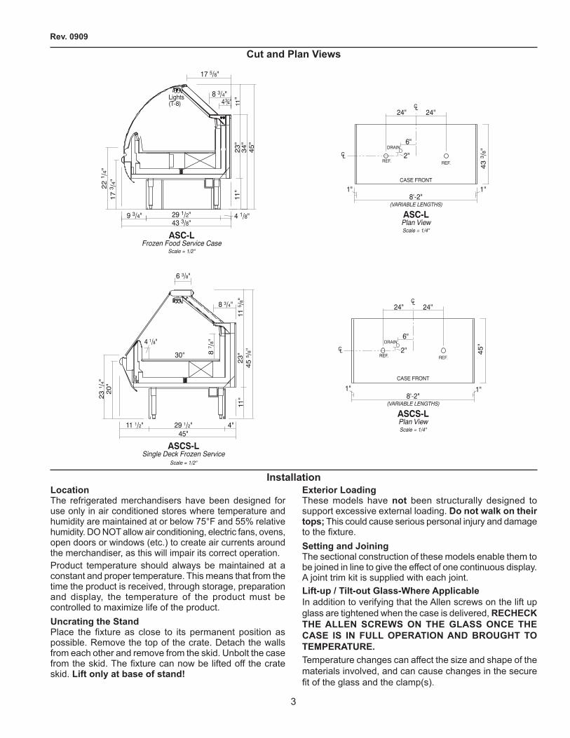
cut and plan views
11"
11"
34"
45"
8 3/4"43/4"
ASC-LFrozen Food Service Case
Scale = 1/2"
43 3/8"
17 5/8"
17
3/4
"
9 3/4" 29 1/2" 4 1/8"
23"
22
1/4
"Lights(T-8)
ASCS-LSingle Deck Frozen Service
Scale = 1/2"
20"
23
1/4
"
45
5/8
"
87/8
"
115/8
"23"
1 1"
4 1/8"
45"29 1/2" 4"
30"
8 3/4"
11 1/2"
6 3/8"
43
3/8
"
24"
CASE FRONT
ASC-LPlan ViewScale = 1/4"
8'-2"(VARIABLE LENGTHS)
"1"1
DRAIN
24"CL
6"
REF.REF.CL 2"
45"
24"
CASE FRONT
ASCS-LPlan ViewScale = 1/4"
8'-2"(VARIABLE LENGTHS)
1" 1"
DRAIN
24"CL
6"
REF.REF.CL 2"
installationlocationThe refrigerated merchandisers have been designed for use only in air conditioned stores where temperature and humidity are maintained at or below 75°F and 55% relative humidity. DO NOT allow air conditioning, electric fans, ovens, open doors or windows (etc.) to create air currents around the merchandiser, as this will impair its correct operation.Product temperature should always be maintained at a constant and proper temperature. This means that from the time the product is received, through storage, preparation and display, the temperature of the product must be controlled to maximize life of the product.uncrating the standPlace the fixture as close to its permanent position as possible. Remove the top of the crate. Detach the walls from each other and remove from the skid. Unbolt the case from the skid. The fixture can now be lifted off the crate skid. lift only at base of stand!
exterior loadingThese models have not been structurally designed to support excessive external loading. do not walk on their tops; This could cause serious personal injury and damage to the fixture.setting and JoiningThe sectional construction of these models enable them to be joined in line to give the effect of one continuous display. A joint trim kit is supplied with each joint.lift-up / tilt-out glass-Where applicableIn addition to verifying that the Allen screws on the lift up glass are tightened when the case is delivered, rechecK the allen screWs on the glass once the case is in full operation and Brought to temperature.Temperature changes can affect the size and shape of the materials involved, and can cause changes in the secure fit of the glass and the clamp(s).

igsf-asc-l/ascs-l-0909
4
levelingimportant! it is imperative that cases Be leveled from front to BacK and side to side prior to Joining. a level case is necessarY to insure proper operation, Water drainage, glass alignment, and operation of the hinges supporting the glass. leveling the case correctlY Will solve most hinge operation proBlems.NOTE: A. To avoid removing concrete flooring, begin lineup
leveling from the highest point of the store floor. B. When wedges are involved in a lineup, set them first.
All cases were leveled and joined prior to shipment to insure the closest possible fit when cases are joined in the field. When joining, use a carpenters level and shim legs accordingly. Case must be raised correctly, under legs where support is best, to prevent damage to case.
1. Check level of floor where cases are to be set. Determine the highest point of the floor; cases will be set off this point.
2. Set first case, and adjust legs over the highest part of the floor so that case is level. Prevent damage-case must be raised under leg or by use of �x6 or �x4 leg brace. Remove side and back leg braces after case is set.
3. Set second case as close as possible to the first case, and level case to the first using the instructions in step one.
4. Apply masking tape 1/8" in from end of case on inside and outside rear mullion on both cases to be joined.
5. Apply liberal bead of case joint sealant (butyl) to dotted area shown in (Fig.2, #1) of first case. Apply heavy amount to cover entire shaded area.
DO NOT USE PERMAGUM!
It is the contractor’s responsibility to installcase(s) according to local construction and
health codes
6. Slide second case up to first case snugly. Then level second case to the first case so glass front, bumper and top are flush.
7. To compress silicone at joint, use two Jurgenson wood clamps. Make sure case is level from front to back and side to side on inside bulkheads at joint.
8. Attach sections together via a � bolts located in the base of the case. Secure the overhead structure by bolting the bracket, located inside behind lights.
Do not use cam locks to pull cases together.
9. Apply bead of silicone to top of bulkheads and slip on stainless steel bulkhead cap. Also apply silicone to seam between overhead light tubes.
Joint trimAfter cases have been leveled and joined, and refrigeration, electrical, and wasted piping work completed, install the splashguards. Fasten along the top edge, or center, with #10 X 3/3" sheet metal screws.
DO NOT SEAL JOINT TRIM TO FLOOR!
GLASS BREAKAGE MAY OCCUR!Retighten glass along glass clamp afterleveling and first time case is brought
to full operating temperature!
installation (cont'd)

rev. 0909
5
installation (cont'd)Bumper installation instructions
Step 1: Make sure the aluminum channel and end caps are installed.
Step �: Use silicone lubricant to help the bumper slide into the channel.
Step 3: Starting on one end: while inserting the bumper, push it up against the end cap to prevent the bumper from shrinking after installation (when it gets cold).
Step 4: As you insert the bumper into the channel with one hand, pull the bumper toward you with the other to open the inside lips. Slowly apply pressure by rolling the bumper into the track.
igsf-asc-l/ascs-l-0909
6
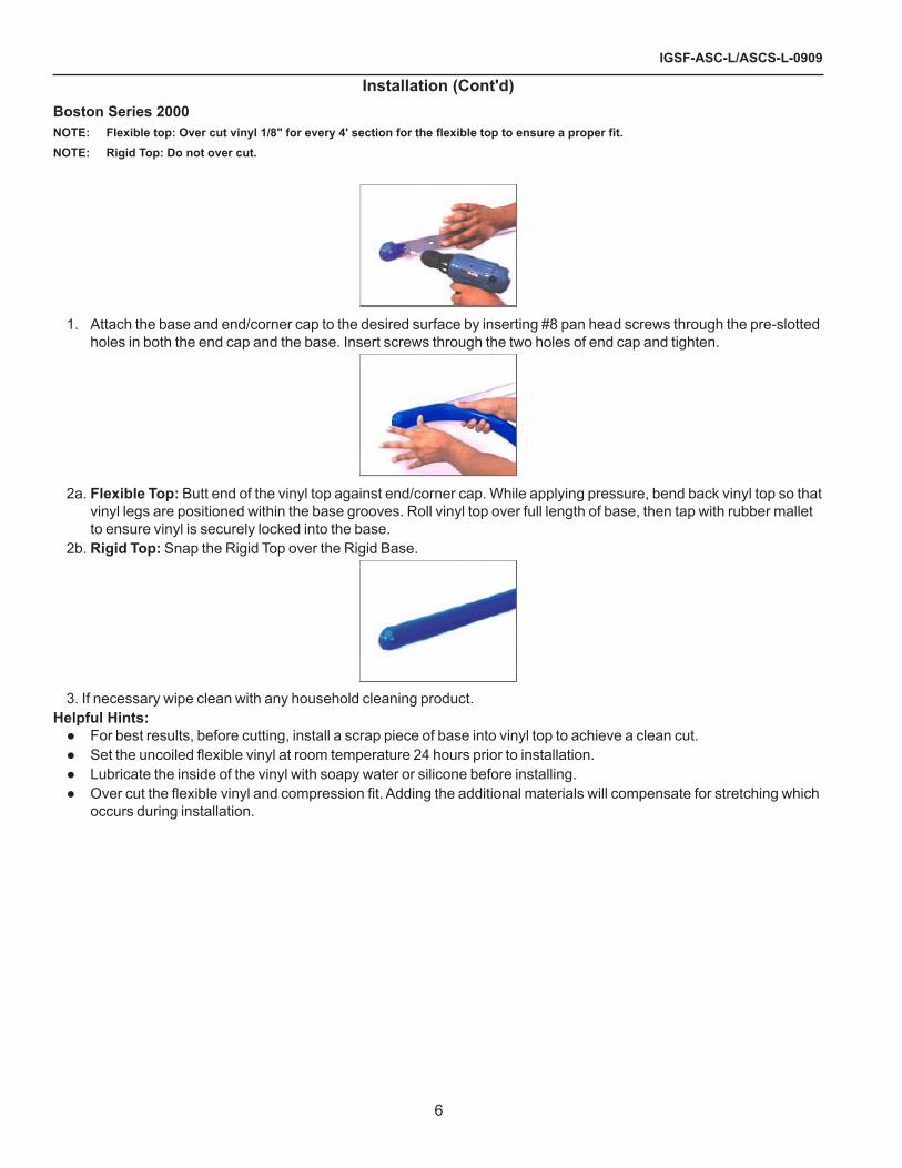
installation (cont'd)Boston series 2000NOTE: Flexible top: Over cut vinyl 1/8" for every 4' section for the flexible top to ensure a proper fit.note: rigid top: do not over cut.
1. Attach the base and end/corner cap to the desired surface by inserting #8 pan head screws through the pre-slotted holes in both the end cap and the base. Insert screws through the two holes of end cap and tighten.
�a. flexible top: Butt end of the vinyl top against end/corner cap. While applying pressure, bend back vinyl top so that vinyl legs are positioned within the base grooves. Roll vinyl top over full length of base, then tap with rubber mallet to ensure vinyl is securely locked into the base.
�b. rigid top: Snap the Rigid Top over the Rigid Base.
3. If necessary wipe clean with any household cleaning product.helpful hints:
● For best results, before cutting, install a scrap piece of base into vinyl top to achieve a clean cut.● Set the uncoiled flexible vinyl at room temperature 24 hours prior to installation.● Lubricate the inside of the vinyl with soapy water or silicone before installing.● Over cut the flexible vinyl and compression fit. Adding the additional materials will compensate for stretching which
occurs during installation.

rev. 0909
7
installation (cont'd)Boston 2000 eco series
1. Attach the base and end/corner cap to the desired surface by inserting #8 pan head screws through the pre-slotted holes in both the end cap and the base. Insert screws through the two holes of end cap and tighten.
�a. flexible top: Butt end of the vinyl top against end/corner cap. While applying pressure, bend back vinyl top so that vinyl legs are positioned within the base grooves. Roll vinyl top over full length of base, then tap with rubber mallet to ensure vinyl is securely locked into the base.
�b. rigid top: Snap the Rigid Top over the Rigid Base.
3. If necessary wipe clean with any household cleaning product.helpful hints:
● For best results, before cutting, install a scrap piece of base into vinyl top to achieve a clean cut.● Set the uncoiled flexible vinyl at room temperature 24 hours prior to installation.● Lubricate the inside of the vinyl with soapy water or silicone before installing.● Over cut the flexible vinyl and compression fit. Adding the additional materials will compensate for stretching which
occurs during installation.
igsf-asc-l/ascs-l-0909
8
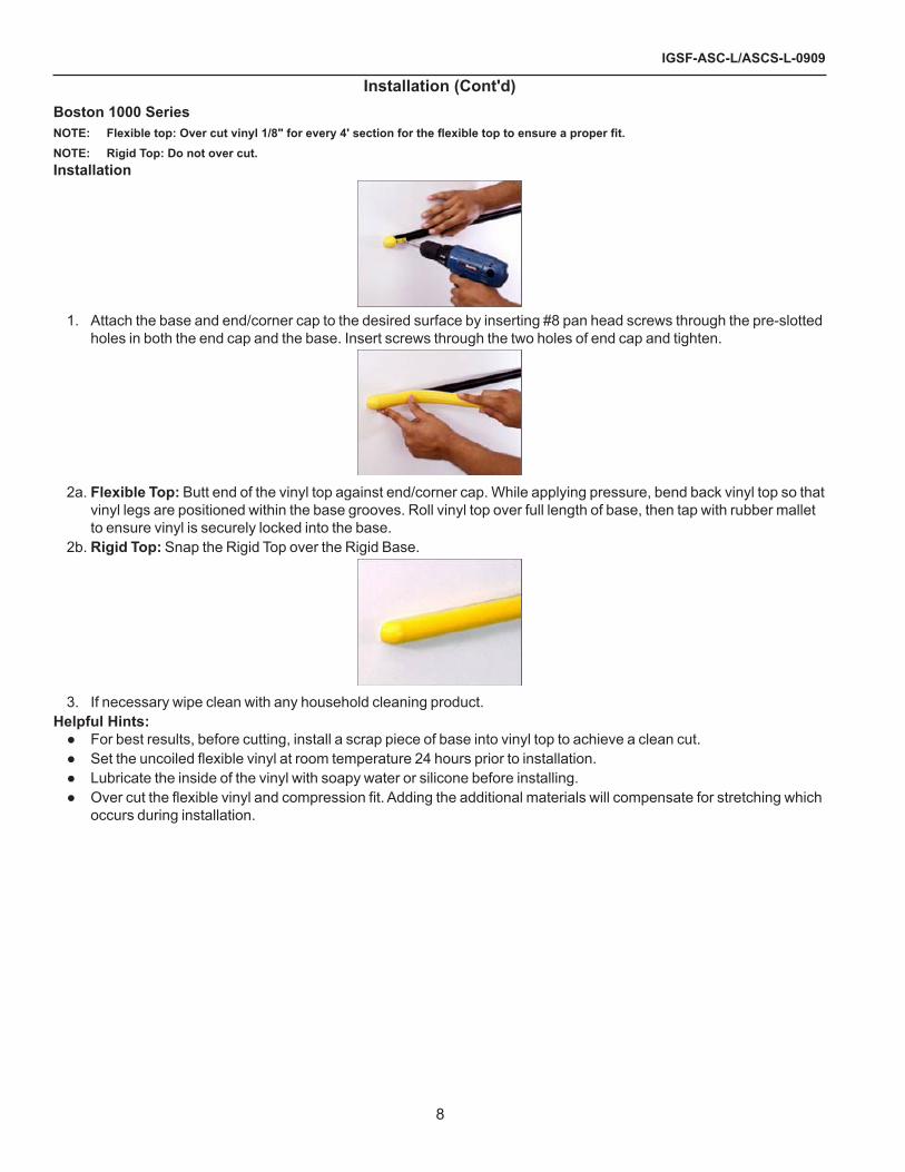
installation (cont'd)Boston 1000 seriesNOTE: Flexible top: Over cut vinyl 1/8" for every 4' section for the flexible top to ensure a proper fit.note: rigid top: do not over cut.installation
1. Attach the base and end/corner cap to the desired surface by inserting #8 pan head screws through the pre-slotted holes in both the end cap and the base. Insert screws through the two holes of end cap and tighten.
�a. flexible top: Butt end of the vinyl top against end/corner cap. While applying pressure, bend back vinyl top so that vinyl legs are positioned within the base grooves. Roll vinyl top over full length of base, then tap with rubber mallet to ensure vinyl is securely locked into the base.
�b. rigid top: Snap the Rigid Top over the Rigid Base.
3. If necessary wipe clean with any household cleaning product.helpful hints:
● For best results, before cutting, install a scrap piece of base into vinyl top to achieve a clean cut.● Set the uncoiled flexible vinyl at room temperature 24 hours prior to installation.● Lubricate the inside of the vinyl with soapy water or silicone before installing.● Over cut the flexible vinyl and compression fit. Adding the additional materials will compensate for stretching which
occurs during installation.

rev. 0909
9
plumbingWaste outlet and p-trapThe waste outlet is located off the center of the case on one side allowing drip piping to be run lengthwise under the fixture.A 1-1/�" P-TRAPS and threaded adapters are supplied with each fixture. The P-TRAP must be installed to prevent air leakage and insect entrance into the fixture.note: pvc-dWv solvent cement is recommended. follow the
manufacturer’s instructions.installing condensate drainPoorly or improperly installed condensate drains can seriously interfere with the operation of this refrigerator, and result in costly maintenance and product losses. Please follow the recommendations listed below when installing condensate drains to insure a proper installation:
1. Never use pipe for condensate drains smaller than the nominal diameter of the pipe or P-TRAP supplied with the case.
�. When connecting condensate drains, the P-TRAP must be used as part of the condensate drain to prevent air leakage or insect entrance. Store plumbing system floor drains should be at least 14" off the center of the case to allow use of the P-TRAP pipe section. Never use two water seals in series in any one line. Double P-TRAPS in series will cause a lock and prevent draining.
3. Always provide as much down hill slope ("fall") as possible; 1/8" per foot is the preferred minimum. PVC pipe, when used, must be supported to maintain the 1/8" pitch and to prevent warping.
4. Avoid long runs of condensate drains. Long runs make it impossible to provide the "fall" necessary for good drainage.
5. Provide a suitable air break between the flood rim of the floor drain and outlet of condensate drain. 1" is ideal.
6. Prevent condensate drains from freezing:a. Do not install condensate drains in contact with
non-insulated suction lines. Suction lines should be insulated with a non - absorbent insulation material such as Armstrong's Armaflex.
b. Where condensate drains are located in dead air spaces (between refrigerators or between a refrigerator and a wall), provide means to prevent freezing. The water seal should be insulated to prevent condensation.
refrigerationgelato/soft ice creamThese display cases are designed to hold product at temperatures that will allow operators to scoop or dip gelato and soft ice cream into cones, containers or dishes. The temperatures will fall in the range of plus 4°F to plus 1�°F depending on amount of sugar and butter fat in product. The temperature and condition of product must be checked after being in case the first four hours of operation. Because of the sensitive condition of these products, defrost is very critical. The fans do NOT run during defrost periods. The maximum time is �0 minutes for electric and 10 minutes for hot gas and Kool Gas. The fans are on a � minute delay after defrost to avoid adding heat to case.If, because of ambient conditions, the defrost must be changed, amount of defrosts not time is necessary. i.e., 3 by �0 minutes instead of � x 40 minutes.refrigerant typeThe standard refrigerant will be R-404 unless otherwise specified on the customer order. Check the serial plate on the case for information.Piping for more than one case on a condensing unit is run underground with either common suction and liquid lines from the machine room or individual suction and liquid lines joined together in the machine room.refrigeration lines
Liquid Suction3/8” O.D. 5/8” O.D.
note: the standard coil is piped at 5/8” (suction); however, the store tie-in may vary depending on the number of coils and the draw the case has. depending on the case setup, the connecting point in the store may be 5/8”, 7/8”, or 11/8”. refer to the particular case you are hooking up.
Refrigerant lines should be sized as shown on the refrigeration legend furnished by the store.Install p-traps (oil traps) at the base of all suction line vertical risers.pressure drop can rob the system of capacity. To keep the pressure drop to a minimum, keep refrigerant line run as short as possible, using the minimum number of elbows. Where elbows are required, use long radius elbows only.control settingsSee ASC-L/ASCS-L technical data sheet for the appropriate settings for your merchandiser. Maintain these parameters to achieve near constant product temperatures. Product temperature should be measured first thing in the morning, after having been refrigerated overnight. Defrost times should as directed in the ASC-L/ASCS-L technical data sheet. The number of defrosts per day should never change. The duration of the defrost cycle may be adjusted to meet conditions present at your location.control settings-self containedOn Self Contained cases all functions, defrost, fans, temperature are controlled by Pagon ERC-� controller. See ASC-L/ASCS-L technical data sheet for proper temperature and defrost settings.
igsf-asc-l/ascs-l-0909
10
access to tX valves and drain linesmechanical - Remove product from end of case. Remove product racks. Remove refrigeration and drain access panels (labeled). TX valve (mechanical only) and drain are located under each access panel at end of the case.electronic - The Electronic Expansion valve master and slave cylinder(s) are located within the electrical access panel(s).electronic expansion valve (optional)A wide variety of electronic expansion valves and case controllers can be utilized. Please refer to EEV and controller manufacturers information sheet. Sensors for electronic expansion valves will be installed on the coil inlet, coil outlet, and in the discharge air. (Some supermarkets require a 4th sensor in the return air). Case controllers will be located in the electrical raceway or under the case.thermostatic expansion valve locationThis device is located on the same side as the refrigeration stub. An Alco balanced port expansion valve model is furnished as standard equipment, unless otherwise specified by customer.expansion valve adjustmentExpansion valves must be adjusted to fully feed the evaporator. Before attempting any adjustments, make sure the evaporator is either clear or very lightly covered with frost, and that the fixture is within 10°F of its expected operating temperature.measuring the operating superheat
1. Determine the suction pressure with an accurate pressure gauge at the evaporator outlet.
�. From a refrigerant pressure temperature chart, determine the saturation temperature at the observed suction pressure.
3. Measure the temperature of the suction gas at the thermostatic remote bulb location.
4. Subtract the saturation temperature obtained in step No. � from the temperature measured in step No. 3.
5. The difference is superheat.6. Set the superheat for 5°F - 7°F.
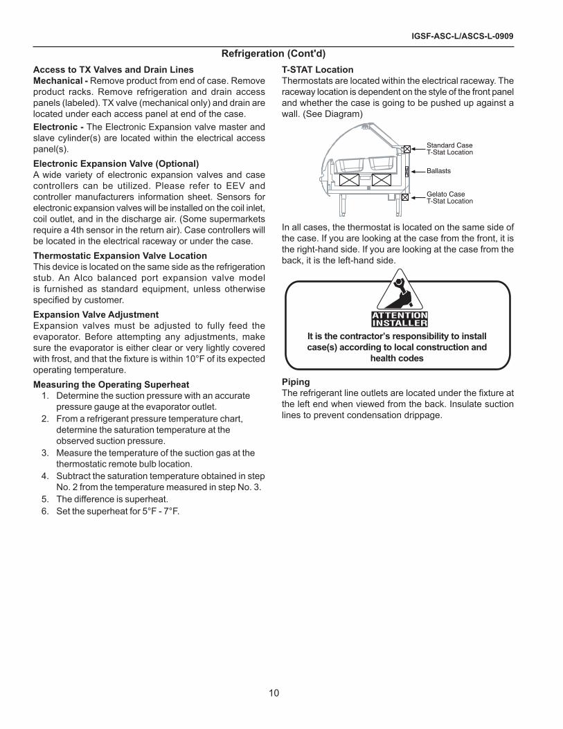
t-stat locationThermostats are located within the electrical raceway. The raceway location is dependent on the style of the front panel and whether the case is going to be pushed up against a wall. (See Diagram)
Standard CaseT-Stat Location
Ballasts
Gelato CaseT-Stat Location
In all cases, the thermostat is located on the same side of the case. If you are looking at the case from the front, it is the right-hand side. If you are looking at the case from the back, it is the left-hand side.
It is the contractor’s responsibility to installcase(s) according to local construction and
health codes
pipingThe refrigerant line outlets are located under the fixture at the left end when viewed from the back. Insulate suction lines to prevent condensation drippage.
refrigeration (cont'd)

rev. 0909
11
refrigeration datanote: this data is based on store temperature and humidity
that does not exceed 75f and 55% r.h.
frozen fooddischarge air (f) -10 evaporator (f) -20
ice creamdischarge air (f) -20 evaporator (f) -30
asc-l 4’ frozen pasta (electric defrost)discharge air (f) 5evaporator (f) 0
note: not recommended to control temp by regulating coil temp allow t-stat to cycle and control temp.
Btu/hr/ft* frozen foodparallel 650conventional 748 ice creamparallel 800conventional 920asc-l 4’ frozen pasta (electric defrost)parallel 550conventional 633*For all refrigeration equipment other than Hussmann use conventional Btu values.
defrost dataelectric defrost optionfrequency hrs 24offtimetemp term °f 54failsafe minutes 60Kool-gas™ defrost optionfrequency hrs 24offtimetemp term °f 54failsafe minutes 60physical dataMerchandiser Drip Pipe (in.) 1 ½*Merchandiser Liquid Line (in.) 3/8*Merchandiser Suction Line (in.) 5/8*Estimated Charge (lb) 4ft 1.7 6ft �.5 8ft 3.5 10ft 4.� 1�ft 5.0*Dependent on case length and refrigerant type.glycol requirementsgpm psin/a n/an/a n/an/a n/a
refrigeration (cont'd)

igsf-asc-l/ascs-l-0909
1�
paragon erc 2 electronic controller for self contained cases
The erc 2 electronic refrigeration control is a microprocessor-based electronic controller designed to control both the temperature and the defrost functions of a commercial refrigeration unit. It can be powered by 1�0, �08 or �40 VAC (50 or 60Hz). The control comes with four relay outputs: compressor, defrost, evaporator fan and alarm.The ERC � includes a digital display module that provides readout of the temperature, time and built-in diagnostics. The display module can be mounted locally or remotely from the unit and it contains a touch keypad for simple programming. For defrost control, the unit uses a real time clock.This control is NSF certified and it can be applied to many different commercial refrigeration applications like reach-ins, walk-ins, refrigerated cases or other different products where accurate control of refrigerated space and defrost cycles is required.Features / Benefitsmulti-function unit Integrates defrost timer, temperature control, defrost termination switch, fan delay switch and digital thermometer.display module for temperature readout Easy to read display that can be mounted with the unit or remotely. Temperature can be displayed in °F or °C.two temperature sensors For zone temperature and evaporator temperature.choice of defrost methods Off cycle, hot gas or electric heater with up to 8 defrosts per day and duration up to 4 hours.four relay outputs Compressor, defrost, evaporator fan and alarm.
adjustable short cycle protection Extra protection for the equipment.non-volatile memory The programmed parameters will remain in the memory.capacitor carry over for the clock It maintains the correct time-of-day for up to 100 hours. microprocessor-Based electronics High reliability and repeatability.fcc compliance*This device complies with CFR 47, Part 15, Class A FCC Requirements. Operation is subject to the following two conditions,
(1) This device may not cause harmful interference and (�) This device must accept any interference received,
including interference that may cause undesired operation.
canadian compliance*This digital apparatus meets all of the Industry Canada, ICES-003, Class A requirements (Canadian Interference- Causing Equipment Regulations).*note: these compliance apply to nema 1 enclosed models
only. all modular units are the responsibility of the purchaser to obtain the compliance.
operation and functionsThe ERC � features a simple way to program and operate. Four buttons on the display module allow the user to scroll through the functions and set the desired parameters. A manual defrost button is used to initiate the defrost cycle at any time.There are two different levels of security to access the programming features. The first one will allow the change on the time-of-day and the set point temperature (cut-out). The other level will allow access to the other parameters.The programmable parameters are:clock
• Clock: allows time-of-day programming and choice of display format (1� / �4 hours)
general• Display: the display can show time-of-day, zone
temperature, evaporator temperature and it can also cycle between zone temperature and time-of day
• Temperature format: the control can use temperatures in °F or °C
• Fan enable during defrost: to control the fan operation during defrost (on or off)
• Minimum compressor off time: for short cycle protection, between 0 and 15 min
• Minimum compressor on time: between 0 and 15 min
• Alarm delay: a time delay can be configured for the alarm to operate (between 0 and 59 min)

rev. 0909
13
defrost• Defrost type: it can programmed for hot gas or
electric heater defrost. An off cycle defrost type can be configured by selecting the electric defrost option and not connecting any device to the defrost relay
• Number of defrosts per day: between 1 and 8. There is also an option for 1 defrost every 48 hours
• Defrost cycle: a choice among defrost start time (real time clock), accumulated compressor run time or temperature initiation defrost
• Fan delay: amount of time that the fan will remain off after defrost is terminated (0 to 15 min)
• Pump down: amount of time the compressor remains on after defrost initiates (0 to 59 min)
• Drip time: amount of time the compressor is locked out after defrost is terminated (0 to 59 min)
• Defrost duration time: amount of time for the defrost duration. It also functions as a back-up for temperature termination.
• Defrost termination temperature: temperature that will cause the defrost to terminate (if reached before defrost duration time)
• Fan start temperature: temperature that will cause the fan to re-start after defrost
setpoint• Setpoint temperature (cut-out): a setpoint
temperature can be programmed to control the compressor operation. The range is -40 to 60 °F
• Cut-in differential: differential between the cut-out (setpoint) and the cut-in temperature. The range is 1 to �5 °F
• High and low temperature alarm setpoint: high and low alarms for the temperature can be set. The ranges are -40 to 60 °F for each of the alarms (high and low)
graphic description / dimensionsDisplay
Fig. 1
Relay Board Layout
Fig. 2
control Wiring• All wiring should conform to the National Electric
Code and local regulations.• Use copper conductors only.• Electrical leads should not be taut; allow slack for
temperature change and vibration.The wiring diagrams for the ERC � are shown below:
Fig. 7
208/240VAC
Fig. 8
paragon erc 2 electronic controller for self contained cases (cont'd)
igsf-asc-l/ascs-l-0909
14
For �08-�40 VAC, change the jumpers on the connectors located on the left side (from jumpers P3 to P4 and P5 to P6 for 1�0 VAC to a jumper from P4 to P5 for �08-�40 VAC), just like this diagram shows. Neutral becomes L� in �08-�40 VACWiring installation procedure
1. Accessing the terminals• Open the metal case to access the control
connectors. The cable can be disconnected from the display module while the control is being wired. Reconnect the cable before using the unit.
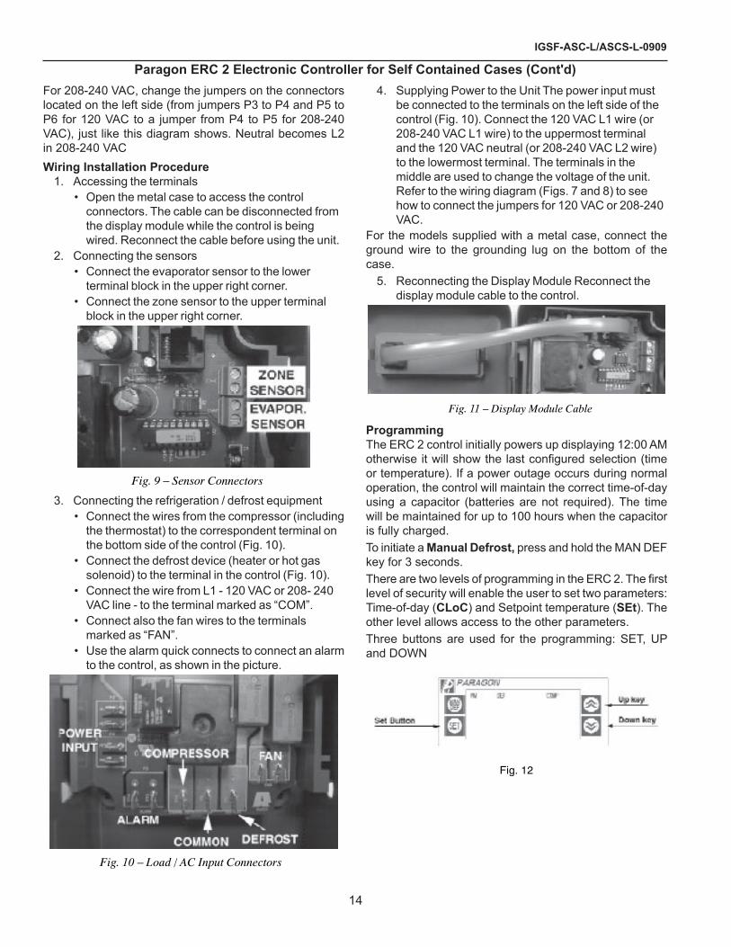
�. Connecting the sensors• Connect the evaporator sensor to the lower
terminal block in the upper right corner.• Connect the zone sensor to the upper terminal
block in the upper right corner.
Fig. 9 – Sensor Connectors
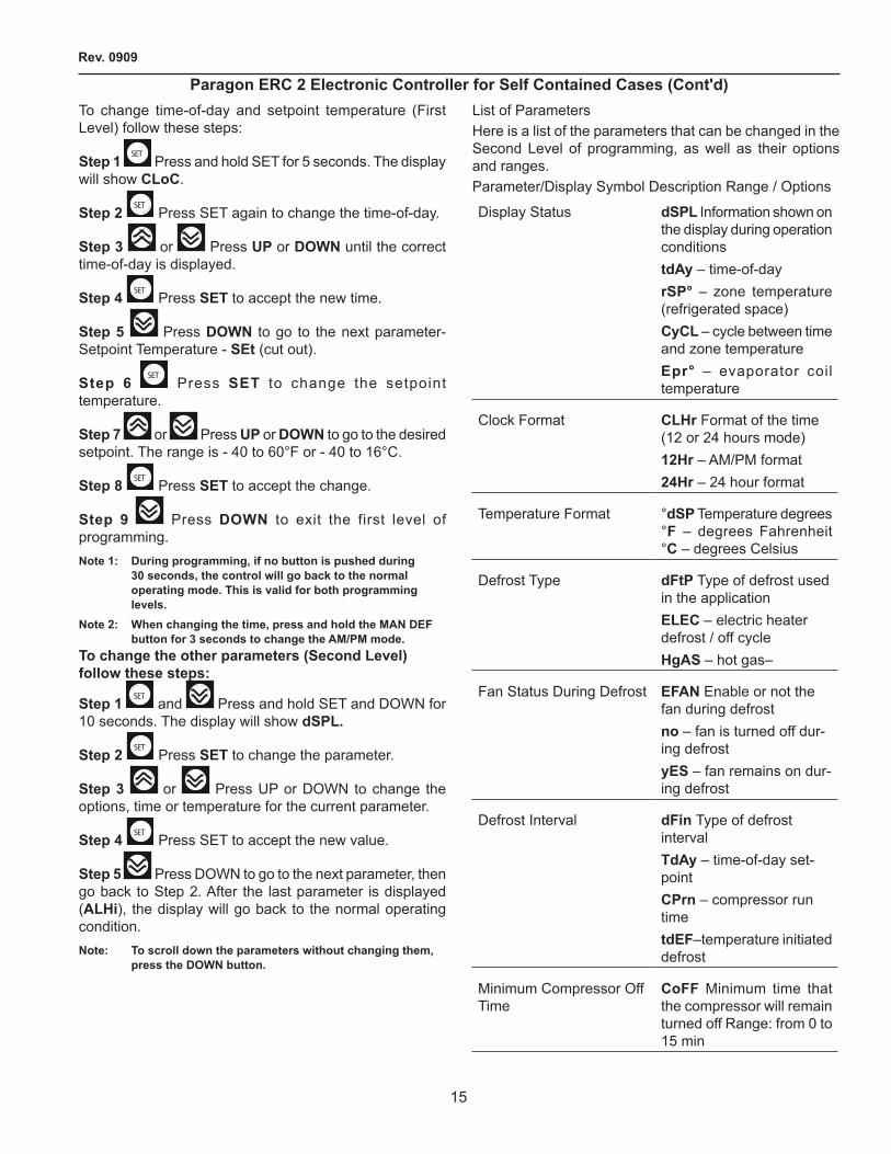
3. Connecting the refrigeration / defrost equipment• Connect the wires from the compressor (including
the thermostat) to the correspondent terminal on the bottom side of the control (Fig. 10).
• Connect the defrost device (heater or hot gas solenoid) to the terminal in the control (Fig. 10).
• Connect the wire from L1 - 1�0 VAC or �08- �40 VAC line - to the terminal marked as “COM”.
• Connect also the fan wires to the terminals marked as “FAN”.
• Use the alarm quick connects to connect an alarm to the control, as shown in the picture.
Fig. 10 – Load / AC Input Connectors
4. Supplying Power to the Unit The power input must be connected to the terminals on the left side of the control (Fig. 10). Connect the 1�0 VAC L1 wire (or �08-�40 VAC L1 wire) to the uppermost terminal and the 1�0 VAC neutral (or �08-�40 VAC L� wire) to the lowermost terminal. The terminals in the middle are used to change the voltage of the unit. Refer to the wiring diagram (Figs. 7 and 8) to see how to connect the jumpers for 1�0 VAC or �08-�40 VAC.
For the models supplied with a metal case, connect the ground wire to the grounding lug on the bottom of the case.
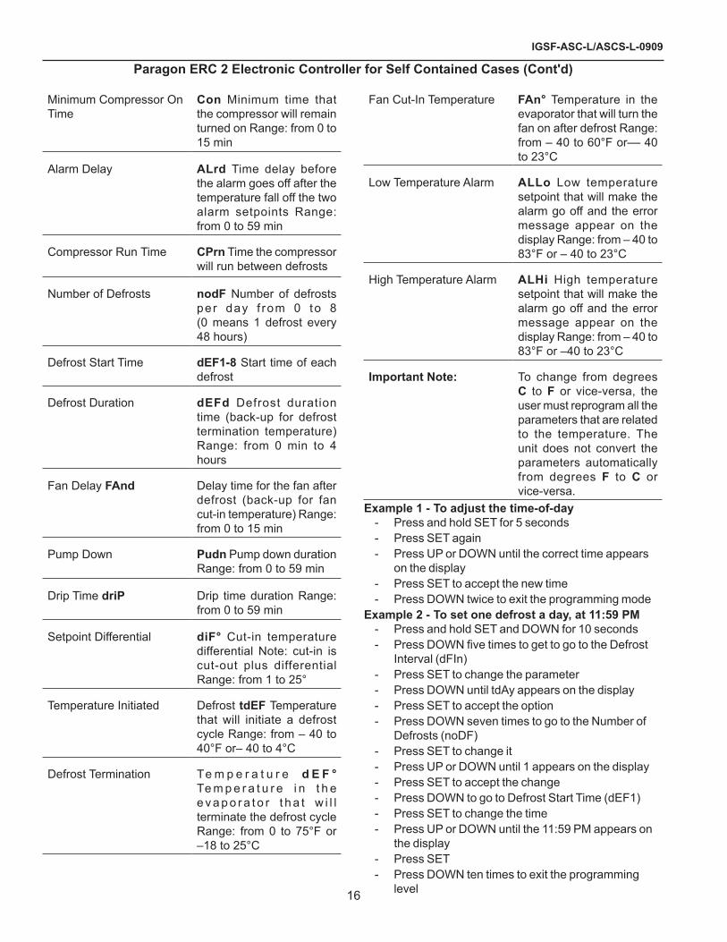
5. Reconnecting the Display Module Reconnect the display module cable to the control.
Fig. 11 – Display Module Cable
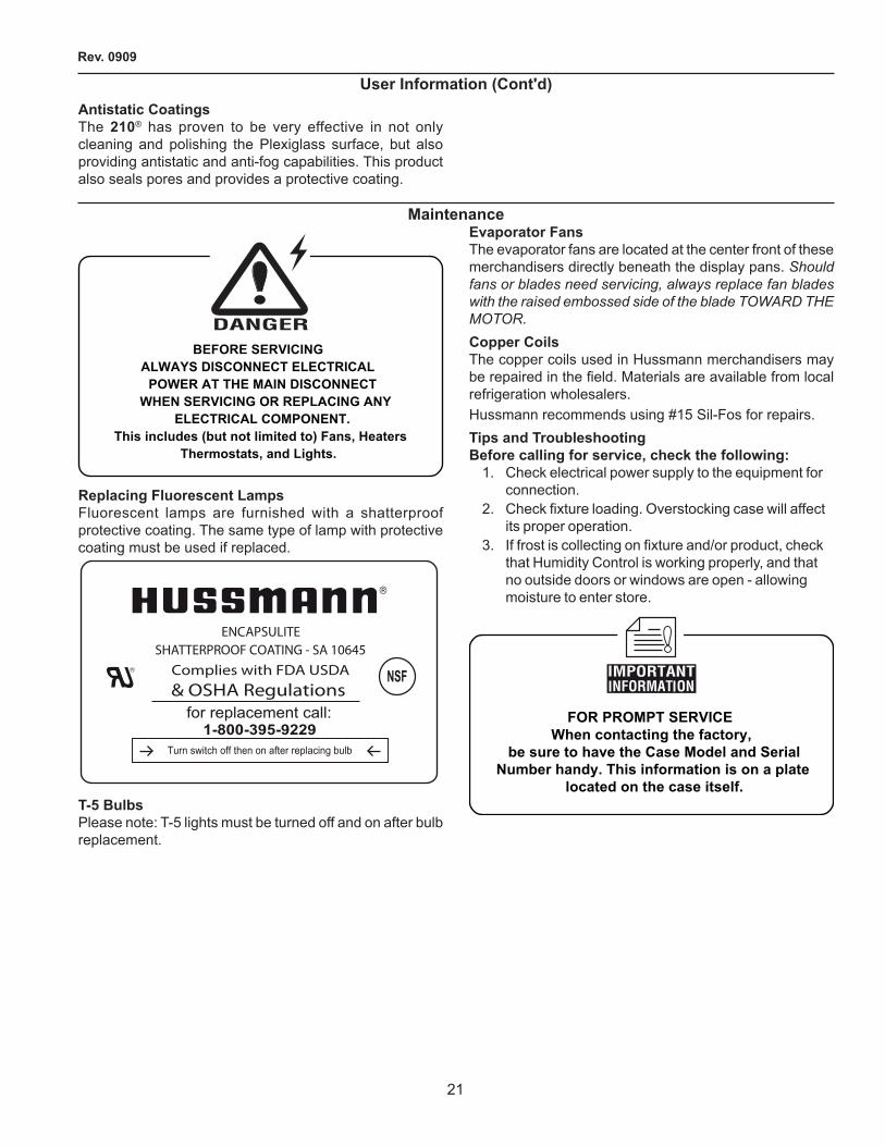
programmingThe ERC � control initially powers up displaying 1�:00 AM otherwise it will show the last configured selection (time or temperature). If a power outage occurs during normal operation, the control will maintain the correct time-of-day using a capacitor (batteries are not required). The time will be maintained for up to 100 hours when the capacitor is fully charged.To initiate a manual defrost, press and hold the MAN DEF key for 3 seconds.There are two levels of programming in the ERC 2. The first level of security will enable the user to set two parameters: Time-of-day (cloc) and Setpoint temperature (set). The other level allows access to the other parameters.Three buttons are used for the programming: SET, UP and DOWN
Fig. 12
paragon erc 2 electronic controller for self contained cases (cont'd)
rev. 0909
15
To change time-of-day and setpoint temperature (First Level) follow these steps:
step 1 SET
Press and hold SET for 5 seconds. The display will show cloc.
step 2 SET Press SET again to change the time-of-day.
step 3 or Press up or doWn until the correct time-of-day is displayed.
step 4 SET
Press set to accept the new time.
step 5 Press doWn to go to the next parameter-Setpoint Temperature - set (cut out).
step 6 SET
Press set to change the setpoint temperature.
step 7 or Press up or doWn to go to the desired setpoint. The range is - 40 to 60°F or - 40 to 16°C.
step 8 SET
Press set to accept the change.
step 9 Press doWn to exit the first level of programming.note 1: during programming, if no button is pushed during
30 seconds, the control will go back to the normal operating mode. this is valid for both programming levels.
note 2: When changing the time, press and hold the man def button for 3 seconds to change the am/pm mode.
to change the other parameters (second level) follow these steps:
step 1 SET
and Press and hold SET and DOWN for 10 seconds. The display will show dspl.
step 2 SET
Press set to change the parameter.
step 3 or Press UP or DOWN to change the options, time or temperature for the current parameter.
step 4 SET
Press SET to accept the new value.
step 5 Press DOWN to go to the next parameter, then go back to Step �. After the last parameter is displayed (alhi), the display will go back to the normal operating condition.note: to scroll down the parameters without changing them,
press the doWn button.
List of ParametersHere is a list of the parameters that can be changed in the Second Level of programming, as well as their options and ranges.Parameter/Display Symbol Description Range / Options
Display Status dspl Information shown on the display during operation conditionstday – time-of-dayrsp° – zone temperature (refrigerated space)cycl – cycle between time and zone temperatureepr° – evaporator coil temperature
Clock Format clhr Format of the time (1� or �4 hours mode)12hr – AM/PM format24hr – �4 hour format
Temperature Format °dsp Temperature degrees °f – degrees Fahrenheit °c – degrees Celsius
Defrost Type dftp Type of defrost used in the applicationelec – electric heater defrost / off cyclehgas – hot gas–
Fan Status During Defrost efan Enable or not the fan during defrostno – fan is turned off dur-ing defrostyes – fan remains on dur-ing defrost
Defrost Interval dfin Type of defrost intervaltday – time-of-day set-pointcprn – compressor run timetdef–temperature initiated defrost
Minimum Compressor Off Time
coff Minimum time that the compressor will remain turned off Range: from 0 to 15 min
paragon erc 2 electronic controller for self contained cases (cont'd)
igsf-asc-l/ascs-l-0909
16
Minimum Compressor On Time
con Minimum time that the compressor will remain turned on Range: from 0 to 15 min
Alarm Delay alrd Time delay before the alarm goes off after the temperature fall off the two alarm setpoints Range: from 0 to 59 min
Compressor Run Time cprn Time the compressor will run between defrosts
Number of Defrosts nodf Number of defrosts per day f rom 0 to 8 (0 means 1 defrost every 48 hours)
Defrost Start Time def1-8 Start time of each defrost
Defrost Duration defd Defrost duration time (back-up for defrost termination temperature) Range: from 0 min to 4 hours
Fan Delay fand Delay time for the fan after defrost (back-up for fan cut-in temperature) Range: from 0 to 15 min
Pump Down pudn Pump down duration Range: from 0 to 59 min
Drip Time drip Drip time duration Range: from 0 to 59 min
Setpoint Differential dif° Cut-in temperature differential Note: cut-in is cut-out plus differential Range: from 1 to �5°
Temperature Initiated Defrost tdef Temperature that will initiate a defrost cycle Range: from – 40 to 40°F or– 40 to 4°C
Defrost Termination Te m p e r a t u r e d e f ° Te m p e r a t u r e i n t h e e v a p o r a t o r t h a t w i l l terminate the defrost cycle Range: from 0 to 75°F or –18 to �5°C
Fan Cut-In Temperature fan° Temperature in the evaporator that will turn the fan on after defrost Range: from – 40 to 60°F or–– 40 to �3°C
Low Temperature Alarm allo Low temperature setpoint that will make the alarm go off and the error message appear on the display Range: from – 40 to 83°F or – 40 to �3°C
High Temperature Alarm alhi High temperature setpoint that will make the alarm go off and the error message appear on the display Range: from – 40 to 83°F or –40 to �3°C
important note: To change from degrees c to f or vice-versa, the user must reprogram all the parameters that are related to the temperature. The unit does not convert the parameters automatically from degrees f to c or vice-versa.
example 1 - to adjust the time-of-day- Press and hold SET for 5 seconds- Press SET again- Press UP or DOWN until the correct time appears
on the display- Press SET to accept the new time- Press DOWN twice to exit the programming mode
example 2 - to set one defrost a day, at 11:59 pm- Press and hold SET and DOWN for 10 seconds- Press DOWN five times to get to go to the Defrost
Interval (dFIn)- Press SET to change the parameter- Press DOWN until tdAy appears on the display- Press SET to accept the option- Press DOWN seven times to go to the Number of
Defrosts (noDF)- Press SET to change it- Press UP or DOWN until 1 appears on the display- Press SET to accept the change- Press DOWN to go to Defrost Start Time (dEF1)- Press SET to change the time- Press UP or DOWN until the 11:59 PM appears on
the display- Press SET- Press DOWN ten times to exit the programming
level
paragon erc 2 electronic controller for self contained cases (cont'd)

rev. 0909
17
paragon erc 2 electronic controller for self contained cases (cont'd)error codesDisplay Control Statuser 1 ERC Fault – software or hardware
failureer 2 ERC Communication Fault
– indicates that there is a problem with the display module cable
er 3 Zone Sensor Fault– indicates an open or shorted temperature sensor
er 4 Evaporator Sensor Fault– indicates an open or shorted evaporator sensor
er 5 ERC Fault – software or hardware failure
er 6 Low Temperature Alarm– indicates that the temperature has dropped below the low alarm setpoint
er 7 High Temperature Alarm– indicates that the temperature has gone above the high alarm setpoint
If the zone temperature sensor fails, the control will use the cycle times it recorded for the last three cycles to control the equipment (based on time). Therefore the food will be preserved in case of failure.If the evaporator sensor fails the control will terminate the defrost cycle based on time.For Error Codes 1, � and 5 cut the power to the unit and correct the problem to reset the display.For Codes 3 and 4, press the UP or DOWN button on the display to reset the error message. If the display still shows the message, the sensor must be replaced.the error codes 6 and 7 will be automatically reset once the temperature is back within the two setpoints.Technical Specificationsinput power: 1�0 / �08-�40 VAC 50/60 Hz (+10,-15%)power consumption: 5VA @ 1�0/�40VACZone temperature sensor: NTC thermistor. Range – 40 to 199°Fevaporator coil sensor: NTC thermistor. Range – 40 to 199°Fambient operating conditions: – 40 to 1��°F; 0 to 95% RH (non condensing)
display module dimensions: �.75”W x 1.10”H x 1.38”Dcase dimensions: 4.40”W x 7.�8”H x 3.80”Dshipping Weight: �.7 lbs.agency approvals: c-UR-us Recognized Component (equivalent to UL and CSA certifications) NSF International Certifiedoutput relay ratings:compressor: spst no
1�0 VAC �08 VAC �40 VACHorsepower Rating (hp)
1 1.5 �
FLA / LRA 16/96 1�/7� 1�/7�Pilot Duty 470 470 470
defrost: spst nc1�0 VAC �08 VAC �40 VAC
R e s i s t i v e Amps
16 16 16
Horsepower Rating (hp)
1/� 3/4 1
Pi lo t Duty (VA)
470 470 470
evaporator fan: spst nc1�0 VAC �08 VAC �40 VAC
R e s i s t i v e Amps
16 16 16
Horsepower Rating (hp)
1/� 3/4 1
FLA / LRA 10/59 8/48 8/48Pi lo t Duty (VA)
470 470 470
alarm: spst no1�0 VAC �08 VAC �40 VAC
R e s i s t i v e Amps
5 5 5
Pi lo t Duty (VA)
�40 �40 �40
ÄPARAGONCommercial Refrigeration ControlsRanco North America,8115 US Route 4�N,Plain City, OH 43064Telephone: 614 873 9000Facsimile: 614 873 933�An Invensys Company,Part # 7515008-001 September 99

igsf-asc-l/ascs-l-0909
18
electricalWiring color code
CASE MUST BE GROUNDEDNOTE: Refer to label affixed to case to determine the actual
configuration as checked in the “TYPE INSTALLED” boxes.
Electrical Circuit IdentificationStandard lighting for all refrigerated models will be full length fluorescent lamps located within the case at the top.The switch controlling the lights, the plug provided for digital scale, and the thermometer are located at the rear of the case mullion.electrical service receptacles (When applicable)The receptacles located on the exterior of the merchandiser are intended for scales and lighted displays. They are not intended nor suitable for large motors or other external appliances.
BEFORE SERVICINGALWAYS DISCONNECT ELECTRICAL
POWER AT THE MAIN DISCONNECTWHEN SERVICING OR REPLACING ANY
ELECTRICAL COMPONENT.This includes (but not limited to) Fans, Heaters
Thermostats, and Lights.
field Wiring and serial plate amperageField Wiring must be sized for component amperes printed on the serial plate. Actual ampere draw may be less than specified. Field wiring from the refrigeration control panel to the merchandisers is required for refrigeration thermostats. Case amperes are listed on the wiring diagram, but always check the serial plate.Ballast locationBallasts are located on the right rear panel.ashrae color codenote: all other manufacturers have no standard sensor codes.Case Control Systems SENSOR COLOR Manufacturer ® > EIL CPC Location Coil Inlet
Color Blue Blue Part# ��5-01-1755 ��5-01-3�55
Coil Outlet Color Red Red Part# ��5-01-1757 ��5-01-31�3
Discharge Air Color Green Green Part# ��5-01-1756 ��5-01-3�60
Return Air Color Purple GreenPart# ��5-01-1758 ��5-01-3�60
Defrost Term. Color White OrangePart# ��5-01-0650 ��5-01-3�54
Liquid Line Color White BluePart# ��5-01-0650 ��5-01-3�55

rev. 0909
19
user informationstockingImproper temperature and lighting will cause serious product loss. Discoloration, dehydration and spoilage can be controlled with proper use of the equipment and handling of product. Product temperature should always be maintained at a constant and proper temperature. This means that from the time the product is received, through storage, preparation and display, the temperature of the product must be controlled to maximize life of the product. Hussmann cases were not designed to “heat up” or “cool down” product - but rather to maintain an item’s proper temperature for maximum shelf life. To achieve the protection required always:
1. Minimize processing time to avoid damaging temperature rise to the product. Product should be at proper temperature.
�. Keep the air in and around the case area free of foreign gasses and fumes or food will rapidly deteriorate.
3. Maintain the display merchandisers temperature controls as outlined in the refrigerator section of this manual.
4. Do not place any product into these refrigerators until all controls have been adjusted and they are operating at the proper temperature. Allow merchandiser to operate a minimum of 6 hours before stocking with any product.
5. When stocking, never allow the product to extend beyond the recommended load limit. air discharge and return air flow must be unobstructed at all times to provide proper refrigeration.
6. There are vents located at the base of the front of the glass, just above the front rail. These vents supply a continuous, gentle flow of air across the front glass which inhibits condensation. do not place any signs or other restrictive objects on the front of the refrigerator that will block these vents.
7. Keep the service doors closed (when applicable). Refrigeration performance will be seriously affected if left open for a prolonged period of time.
8. Avoid the use of supplemental flood or spot lighting. Display light intensity has been designed for maximum visibility and product life at the factory. The use of higher output fluorescent lamps (H.O. and V.H.O.), will shorten the shelf life of the product.
9. In the Gelato Pan configuration, all holes must be filled (if only an empty pan) to prevent air flow disruption.
case cleaningLong life and satisfactory performance of any equipment are dependent upon the care given to it. To insure long life, proper sanitation and minimum maintenance costs, the refrigerator should be thoroughly cleaned frequently. It is essential to establish and regulate cleaning procedures. This will minimize bacteria causing discoloration which leads to degraded product appearance and significantly shortening product shelf life.SHUT OFF FAN DURING CLEANING PROCESS. It can be unplugged within the case, or shut off case at the source. The interior bottom may be cleaned with any domestic soap or detergent based cleaners.The use of hoses and sage machines to clean the inside of the cases is recommended and is an excellent way to clean the coil fins and hard to reach corners of the interior of the cases. Be sure to observe the warnings below when cleaning the case.Sanitizing solutions will not harm the interior bottom, however, these solutions should always be used according to the manufacturer’s directions and should not contain Ammonia.Soap and hot water are not enough to kill this bacteria. A sanitizing solution must be included with each cleaning process to eliminate this bacteria.
1. Allow cases to come to room temperature�. Scrub thoroughly, cleaning all surfaces, with soap
and hot water.3. Rinse with hot water, but do not flood.4. Apply the sanitizing solution according to the
manufacturer’s directions.5. Rinse thoroughly.6. Dry completely before resuming operation.
stainless steel cleaning and careThere are three basic things, which can break down your stainless steel’s passivity layer and allow corrosion.
1. mechanical abrasion Mechanical Abrasion means those things that
will scratch the steels surface. Steel Pads, wire Brushes, and Scrapers are prime examples.
2. Water Water comes out of our tap in varying degrees of
hardness. Depending on what part of the country you live in, you may have hard or soft water. Hard water may leave spots. Also, when heated, hard water leaves deposits behind that if left to sit, will break down the passive layer and rust your stainless steel. Other deposits from food preparation and service must be properly removed.
3. chlorides Chlorides are found nearly everywhere. They
are in water, food and table salt. One of the worst perpetrators of chlorides can come from household and industrial cleaners.

igsf-asc-l/ascs-l-0909
�0
Don’t Despair! Here are a few steps that can help prevent stainless steel rust.
1. use the proper tools When cleaning your stainless steel products, take
care to use non-abrasive tools. Soft Clothes and plastic scouring pads will NOT harm the steel’s passive layer. Stainless steel pads can also be used but the scrubbing motion must be in the same direction of the manufacturer’s polishing marks.
2. clean With the polish lines Some stainless steels come with visible polishing
lines or “grain”. When visible lines are present, you should ALWAYS scrub in a motion that is parallel to them. When the grain cannot be seen, play it safe and use a soft cloth or plastic scouring pad.
3. use alkaline, alkaline chlorinated or non-chloride containing cleaners
While many traditional cleaners are loaded with chlorides, the industry is providing an ever increasing choice of non-chloride cleaners. If you are not sure of your cleaner’s chloride content contact your cleaner supplier. If they tell you that your present cleaner contains chlorides, ask for an alternative. Also, avoid cleaners containing quaternary salts as they also can attack stainless steel & cause pitting and rusting.
4. treat your Water Though this is not always practical, softening hard
water can do much to reduce deposits. There are certain filters that can be installed to remove distasteful and corrosive elements. Salts in a properly maintained water softener are your friends. If you are not sure of the proper water treatment, call a treatment specialist.
5. Keep your food equipment clean Use alkaline, alkaline chlorinated or non-chlorinated
cleaners at recommended strength. Clean frequently to avoid build-up of hard, stubborn stains. If you boil water in your stainless steel equipment, remember the single most likely cause of damage is chlorides in the water. Heating cleaners that contain chlorides has a similar effect.
6. rinse, rinse, rinse If chlorinated cleaners are used you must rinse,
rinse, rinse and wipe dry immediately. The sooner you wipe off standing water, especially when sit contains cleaning agents, the better. After wiping the equipment down, allow it to air dry for the oxygen helps maintain the stainless steel’s passivity film.
7. never use hydrochloric acid (muriatic acid) on stainless steel
8. regularly restore/passivate stainless steel
cleaning glass and mirrorsOnly use a soft cloth and mild glass cleaning for cleaning any glass or mirrored components. Be sure to rinse and/or dry completely.never use hot water on cold glass surfaces! it may shatter and cause serious injury! Allow glass surfaces to warm first.
CLEANING PRECAUTIONS When cleaning: • Do not use high pressure water hoses • Do not introduce water faster then waste outlet can drain • NEVER INTRODUCE WATER ON SELF CONTAINED UNIT
WITH AN EVPORATOR PAN • NEVER USE A CLEANING OR SANITIZING SOLUTION
THAT HAS AN OIL BASE (these will dissolve the butyl sealants) or an AMMONA BASE (this will corrode the copper components of the case)
• TO PRESERVE THE ATTRACTIVE FINISH: • DO USE WATER AND A MILD DETERGENT FOR THE
EXTERIOR ONLY • DO NOT USE A CHLORANITED CLAENER ON ANY
SURFACE • DO NOT USE ABRASIVES OR STEEL WOOL SCOURING
PADS (these will mar the finish)
CAUTION
non-glare glass cleaningThe high optical clarity of this glass is possible due to special coatings on the glass surface itself. To preserve this coating and the optical clarity, keep the glass clean. Water is the only solution recommended to be used to clean the non-glare glass. The damage to the glass from improper, caustic solutions is irreparable.In addition to cleaning the glass with the recommended product, there are precautions that should be taken when working and cleaning the inside of the case.
• When cleaning the inside of the cases, we recommend that the glass be fully opened and covered to prevent solutions from splashing onto the glass and ruining the coating on the inside.
plexiglass and acrylic careImproper cleaning not only accelerates the cleaning cycle but also degrades the quality of this surface. Normal daily buffing motions can generated static cling attracting dust to the surface. Incorrect cleaning agents or cleaning cloths can cause micro scratching of the surface, causing the plastic to haze over time.cleaningHussmann recommends using a clean damp chamois, or a paper towel marked as dust and abrasive free with 210® plastic cleaner and polish available by calling Sumner Labs at 1-800-542-8656. Hard, rough cloths or paper towels will scratch the acrylic and should not be used.
user information (cont'd)
rev. 0909
�1
antistatic coatingsThe 210® has proven to be very effective in not only cleaning and polishing the Plexiglass surface, but also providing antistatic and anti-fog capabilities. This product also seals pores and provides a protective coating.
user information (cont'd)
maintenance
BEFORE SERVICINGALWAYS DISCONNECT ELECTRICAL
POWER AT THE MAIN DISCONNECTWHEN SERVICING OR REPLACING ANY
ELECTRICAL COMPONENT.This includes (but not limited to) Fans, Heaters
Thermostats, and Lights.
replacing fluorescent lampsFluorescent lamps are furnished with a shatterproof protective coating. The same type of lamp with protective coating must be used if replaced.
ENCAPSULITESHATTERPROOF COATING - SA 10645
Complies with FDA USDA& OSHA Regulations
for replacement call:1-800-395-9229
Turn switch off then on after replacing bulb
NSFURR
t-5 BulbsPlease note: T-5 lights must be turned off and on after bulb replacement.
evaporator fansThe evaporator fans are located at the center front of these merchandisers directly beneath the display pans. Should fans or blades need servicing, always replace fan blades with the raised embossed side of the blade TOWARD THE MOTOR.copper coilsThe copper coils used in Hussmann merchandisers may be repaired in the field. Materials are available from local refrigeration wholesalers.Hussmann recommends using #15 Sil-Fos for repairs.tips and troubleshootingBefore calling for service, check the following:
1. Check electrical power supply to the equipment for connection.
2. Check fixture loading. Overstocking case will affect its proper operation.
3. If frost is collecting on fixture and/or product, check that Humidity Control is working properly, and that no outside doors or windows are open - allowing moisture to enter store.
FOR PROMPT SERVICEWhen contacting the factory,
be sure to have the Case Model and SerialNumber handy. This information is on a plate
located on the case itself.
igsf-asc-l/ascs-l-0909
��
electrical Wiring diagrams
asc-l asc-l 4' W0150000 Electric Defrost 6' W0150001
1�' W0150004 asc-l 4' W0150010
8' W015001� 1�' W0150014
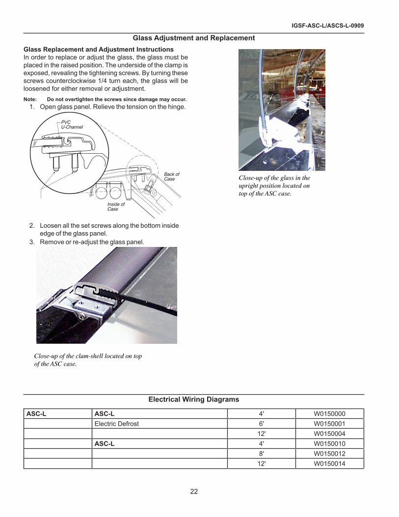
glass adjustment and replacementglass replacement and adjustment instructionsIn order to replace or adjust the glass, the glass must be placed in the raised position. The underside of the clamp is exposed, revealing the tightening screws. By turning these screws counterclockwise 1/4 turn each, the glass will be loosened for either removal or adjustment.note: do not overtighten the screws since damage may occur.
1. Open glass panel. Relieve the tension on the hinge.
Back ofCase
Inside ofCase
PVCU-Channel
�. Loosen all the set screws along the bottom inside edge of the glass panel.
3. Remove or re-adjust the glass panel.
Close-up of the clam-shell located on topof the ASC case.
Close-up of the glass in theupright position located ontop of the ASC case.

rev. 0909
�3
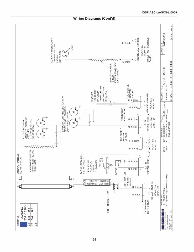
Wiring diagrams
DA
TE:
PR
OJE
CT
TITL
E:
DR
AWIN
G #
:D
RA
WN
BY
:
PR
OD
UC
TIO
N O
RD
ER
#:
DR
AW
ING
TIT
LE:
DA
TE:
Hus
sman
n C
orpo
ratio
n, In
t'l.
1377
0 R
amon
a A
venu
eC
hino
, CA
. 917
10(9
09)-5
90-4
910
L
ic.#
: 644
406
RE
VIS
ION
S:
#:
DE
SC
RIP
TIO
N:
CH
EC
KE
D B
Y:
BY
:
FILE
LO
CA
TIO
N:D
.QU
AN
PA
GE
O
F
?
11
12/1
8/03
AS
C-L
CA
SES
W01
5000
0
4' C
AS
E -
ELE
CTR
IC D
EFR
OS
TA
U
pdat
ed d
wg;
add
ed lo
ad ra
tings
7/
24/0
7
JR
L
3 21
LIG
HT
SW
ITC
HTI
PP
ETT
E12
5-01
-031
1
KLI
XON
™ T
HE
RM
OD
ISK
2042
0D42
-452
-362
L48-
1.8
600-
22-0
050
OP
EN
48
CLO
SE
30
WA
RM
ER
125-
01-0
767
RA
YC
HE
M10
BUT-
CR
-10W
(4Ft
) 40W
.33A
@ 1
20 V
AC
BALLAST 125-01-3266FULHAM LH3-120-L
L1
N
T-ST
AT
LIQ
UID
LIN
ES
OLE
NO
IDV
ALV
E22
5-01
-320
6
CA
P
L1
L2
CA
NO
PY
LIG
HTI
NG
(2) F
25T8
-SPX
30
AN
TI-S
WE
AT H
EATE
R18
0W 1
.5A
@ 1
20 V
AC
125-
01-3
032
AN
TI-S
WE
AT
FAN
SC
OM
AIR
™ R
OTR
ON
®M
X2B
1-E
1(2
) 0.1
8A @
120
VAC
125-
01-2
012-
A
EV
AP
OR
ATO
R F
AN
S E
BM
-PA
PST
™M
OD
EL
9906
L - 0
0001
213
(2) 0
.14A
@ 1
20 V
AC
DE
FRO
ST H
EAT
ER
FIN
NE
D(1
) 150
0W 6
.25A
@ 2
40V
225-
01-0
598C
MM M
M
L1
NL1
N
L1
NL1
N
BLK # 14
WHT # 14
TAG
OR
AN
GE
LIG
HT
CIR
CU
IT ~120
VA
C -
50/6
0 H
zM
CA
= .5
2AM
OP
= 15
A
TAG
WH
ITE
/BLA
CK
T-ST
AT
CIR
CU
IT
~120
VA
C -5
0/60
Hz
BLK # 14
WHT # 14
~120
VA
C -5
0/60
Hz
MC
A= 1
.9A
MO
P=
15A
BLK # 14
WHT # 14
~120
VA
C -5
0/60
Hz
MC
A= .3
2AM
OP
= 15
A
BLK # 14
WHT # 14
~120
VA
C -5
0/60
Hz
MC
A= .4
1AM
OP
= 15
A
BLK # 14
WHT # 14
LIG
HT
CIR
CU
IT=
.42A
TAG
PU
RP
LEH
EAT
ER
CIR
CU
IT
TAG
BR
OW
NFA
N C
IRC
UIT
TAG
PU
RP
LEH
EAT
ER
CIR
CU
IT
BLK # 14
RED # 14
~208
/240
VA
C -5
0/60
Hz
MC
A=
7.8A
MO
P=
15A
CIR
CU
IT #
1
L1 L2 L3
LOA
DIN
G20
8 V
240
V8.
35.
49.
16.
3
igsf-asc-l/ascs-l-0909
�4
Wiring diagrams (cont'd)
DA
TE:
PR
OJE
CT
TITL
E:
DR
AWIN
G #
:D
RA
WN
BY
:
PR
OD
UC
TIO
N O
RD
ER
#:
DR
AW
ING
TIT
LE:
DA
TE:
Hus
sman
n C
orpo
ratio
n, In
t'l.
1377
0 R
amon
a A
venu
eC
hino
, CA
. 917
10(9
09)-5
90-4
910
L
ic.#
: 644
406
RE
VIS
ION
S:
#:
DE
SC
RIP
TIO
N:
CH
EC
KE
D B
Y:
BY
:
FILE
LO
CA
TIO
N:D
.QU
AN
PA
GE
O
F
?
11
12/1
8/03
AS
C-L
CA
SES
W01
5000
1
6' C
AS
E -
ELE
CTR
IC D
EFR
OS
T---
----
L
3 21
LIG
HT
SW
ITC
HTI
PP
ETT
E12
5-01
-031
1
KLIX
ON
™ T
HE
RM
OD
ISK
2042
0D42
-452
-362
L48-
1.8
600-
22-0
050
WA
RM
ER
125-
01-0
767
RA
YC
HE
M10
BUT-
CR
-10W
(6FT
) 60W
0.5A
@12
0 V
AC
BALLAST 125-01-3266FULHAM LH3-120-L
L1
N
T-ST
AT
LIQ
UID
LIN
ES
OLE
NO
IDV
ALV
E22
5-01
-320
6
CA
P
L1
L
2~
208/
240
VA
C -5
0/60
Hz.
CA
NO
PY
LIG
HTI
NG
(2) F
25T8
-SPX
30
AN
TI-S
WE
AT H
EATE
R18
0W 1
.5A
@ 1
20 V
AC
125-
01-3
032
AN
TI-S
WE
AT
FAN
SC
OM
AIR
™ R
OTR
ON
®M
X2B
1-E
1(2
) 0.1
8A @
120
VAC
125-
01-2
012-
A
EV
AP
OR
ATO
R F
AN
S E
BM
-PA
PST
™M
OD
EL
9906
L - 0
0001
213
(2) 0
.14A
@ 1
20 V
AC
DE
FRO
ST H
EAT
ER
FIN
NED
1500
W 6
.25A
@ 2
40V
225-
01-0
598C
BLK # 14
WHT # 14
TAG
OR
AN
GE
LIG
HT
CIR
CU
IT ~120
VA
C -
50/6
0 H
zM
CA=
.52A
MO
P=
15A
LIG
HT
CIR
CU
IT=
.42A
BLK # 14
WHT # 14
TAG
WH
ITE/
BLAC
KT-
STA
T C
IRC
UIT
~120
VA
C -
50/6
0 H
zL1
N
BLK # 14
WHT # 14TAG
PU
RP
LEH
EAT
ER
CIR
CU
IT
~120
VA
C -
50/6
0 H
zM
CA=
1.9
AM
OP
= 15
A
L1
N
BLK # 14
WHT # 14
TAG
BR
OW
NFA
N C
IRC
UIT
~120
VA
C -
50/6
0 H
zM
CA=
.32A
MO
P=
15A
L1
NBLK # 14
WHT # 14
~120
VA
C -
50/6
0 H
zM
CA=
.63A
MO
P=
15A
BLK # 14
RED # 14
MC
A=
7.8A
MO
P=
15A
MM
MM
L1
N
TAG
PU
RP
LEH
EAT
ER
CIR
CU
IT
TO D
EFR
OST
CO
NTR
OL
PA
NE
L
A
Upd
ated
dw
g; a
dded
load
ratin
gs
7/26
/07
J
R
CIR
CU
IT #
1
L1 L2 L3
LOA
DIN
G20
8 V
240
V8.
55.
49.
36.
3

rev. 0909
�5
Wiring diagrams (cont'd)
DA
TE:
PR
OJE
CT
TITL
E:
DR
AWIN
G #
:D
RA
WN
BY
:
PR
OD
UC
TIO
N O
RD
ER
#:
DR
AW
ING
TIT
LE:
DA
TE:
Hus
sman
n C
orpo
ratio
n, In
t'l.
1377
0 R
amon
a A
venu
eC
hino
, CA
. 917
10(9
09)-5
90-4
910
L
ic.#
: 644
406
RE
VIS
ION
S:
#:
DE
SC
RIP
TIO
N:
CH
EC
KE
D B
Y:
BY
:
FILE
LO
CA
TIO
N:AD
RIA
N E
. CR
ISC
I
PA
GE
O
F
?
11
11/2
6/02
AS
C-L
CA
SES
W01
5000
4
12' C
AS
E -
ELE
CTR
IC D
EFR
OS
T
9555
38
L
3 21
LIG
HT
SW
ITC
HTI
PP
ETT
E12
5-01
-031
1
KLI
XON
™ T
HER
MO
DIS
K20
420D
42-4
52-3
62L4
8-1.
860
0-22
-005
0
BALLAST 125-01-3266FULHAM LH3-120-L
T-S
TAT
SU
CTI
ON
SO
LEN
OID
VA
LVE
CAP
L1
L
2~
208/
240
VA
C -
50/6
0 H
z.
CAN
OP
Y L
IGH
TIN
G(2
) F25
T8-S
PX30
AN
TI-S
WE
AT
FAN
SC
OM
AIR
™ R
OTR
ON
®M
X2B
1-E
1(2
) 0.1
8A @
120
VA
C12
5-01
-201
2-A
EV
AP
OR
ATO
R F
AN
S E
BM
-PAP
ST™
MO
DE
L 99
06L
- 000
0121
3(2
) 0.1
4A @
120
VA
C
L
3 21
LIG
HT
SW
ITC
HTI
PP
ETT
E12
5-01
-031
1
KLI
XON
™ T
HER
MO
DIS
K20
420D
42-4
52-3
62L4
8-1.
860
0-22
-005
0
BALLAST 125-01-3266FULHAM LH3-120-L
T-S
TAT
SU
CTI
ON
SOLE
NO
IDV
ALV
E
CAP
CA
NO
PY L
IGH
TIN
G(2
) F25
T8-S
PX30
AN
TI-S
WE
AT
FAN
SC
OM
AIR
™ R
OTR
ON
®M
X2B1
-E1
(2) 0
.18A
@ 1
20 V
AC
125-
01-2
012-
A
EV
AP
OR
ATO
R F
AN
S E
BM
-PAP
ST™
MO
DE
L 99
06L
- 000
0121
3(2
) 0.1
4A @
120
VA
C
LEFT
SID
E C
AS
ER
IGH
T S
IDE
CA
SE
MM M
MM
MMM
L1
L
2~
208/
240
VA
C -
50/6
0 H
z.L1
N
BLK # 14
WHT # 14
TAG
OR
AN
GE
LIG
HT
CIR
CU
IT
~120
VA
C -
50/6
0 H
zM
CA=
.52A
MO
P= 1
5A
LIG
HT
CIR
CU
IT=
.42A
L1
N
BLK # 14
WHT # 14
TAG
OR
AN
GE
LIG
HT
CIR
CU
IT
~120
VA
C -
50/6
0 H
zM
CA
= .5
2AM
OP
= 15
A
LIG
HT
CIR
CU
IT=
.42A
BLK # 14
WHT # 14
TAG
WH
ITE
/BLA
CK
T-S
TAT
CIR
CU
IT
~120
VA
C -
50/6
0 H
zL1
N
BLK # 14
WHT # 14
TAG
WH
ITE
/BLA
CK
T-S
TAT
CIR
CU
IT
~120
VA
C -
50/6
0 H
zL1
N
L1
N
BLK # 14
WHT # 14
TAG
PU
RPL
EH
EATE
RC
IRC
UIT
~120
VA
C -
50/6
0 H
zM
CA=
1.9
AM
OP
= 15
A
L1
N
BLK # 14
WHT # 14
TAG
PU
RP
LEH
EA
TER
CIR
CU
IT
~120
VA
C -
50/6
0 H
zM
CA=
2.2
AM
OP
= 15
A
L1
N
BLK # 14
WHT # 14
TAG
BR
OW
NFA
N C
IRC
UIT
MC
A= .3
2AM
OP
= 15
A
L1
N
BLK # 14
WHT # 14
TAG
BR
OW
NFA
N C
IRC
UIT
MC
A= .3
2AM
OP=
15A
TAG
PU
RP
LEH
EATE
RC
IRC
UIT
L1
N
BLK # 14
WHT # 14
~120
VA
C -
50/6
0 H
z
MC
A= .6
3AM
OP=
15A
TAG
PU
RP
LEH
EATE
RC
IRC
UIT
L1
N
BLK # 14
WHT # 14
~120
VA
C -
50/6
0 H
zM
CA=
.63A
MO
P=
15A
WA
RM
ER12
5-01
-076
7R
AYC
HEM
10B
UT-
CR
-10W
(6FT
) 60W
0.5A
@12
0 V
AC
WA
RM
ER12
5-01
-076
7R
AYC
HEM
10B
UT-
CR
-10W
(6FT
) 60W
0.5A
@12
0 V
AC
DEF
RO
ST
HE
ATE
RFI
NN
ED15
00W
6.2
5A@
240
V22
5-01
-059
8C
DE
FRO
ST
HE
ATE
RFI
NN
ED15
00W
6.2
5A@
240
V22
5-01
-059
8C
AN
TI-S
WE
AT
HEA
TER
180W
1.5
A@
120
VA
C12
5-01
-303
2
AN
TI-S
WE
AT
HE
ATE
R18
0W 1
.5A
@ 1
20 V
AC
125-
01-3
032
MC
A= 7
.8A
MO
P= 1
5AM
CA=
7.8
AM
OP=
15A
L1
N
BLK # 14
WHT # 14
TAG
OR
AN
GE
LIG
HT
CIR
CU
IT
~120
VA
C -
50/6
0 H
zM
CA=
.52A
MO
P= 1
5A
BLK # 14
WHT # 14
~120
VA
C -
50/6
0 H
zL1
N
L1
N
BLK # 14
WHT # 14
TAG
BR
OW
NFA
N C
IRC
UIT
MC
A= .3
2AM
OP=
15A
BLK # 14
RED # 14
BLK # 14
RED # 14
TO D
EFR
OS
T C
ON
TRO
LP
AN
EL
TO D
EFR
OS
T C
ON
TRO
LP
AN
EL
CIR
CU
IT #
1
L1 L2 L3
LOA
DIN
G20
8 V
240
V8.
55.
49.
36.
3
A
Upd
ated
dw
g; a
dded
load
ratin
gs
7/26
/07
J
R
CIR
CU
IT #
2
L1 L2 L3
LOA
DIN
G20
8 V
240
V8.
55.
49.
36.
3

IGSF-ASC-L/ASCS-L-0909
26
Wiring Diagrams (Cont'd)
DA
TE:
PR
OJE
CT
TITL
E:
DR
AW
ING
#:
DR
AW
N B
Y:
PR
OD
UCT
ION
OR
DE
R #
:D
RA
WIN
G T
ITLE
:D
ATE
:R
EVI
SIO
NS:
#:
DE
SC
RIP
TIO
N:
CH
EC
KE
D B
Y:
BY:
FILE
LO
CAT
ION
:D.Q
UA
N--
-
PAG
E
OF
Hus
sman
n C
orpo
ratio
n, In
t'l.
1377
0 R
amon
a A
venu
eC
hino
, CA
. 917
10(9
09)-
590-
4910
L
ic.#
: 644
406
11
07/1
5/01
1 2 3F:
\WIR
ES
CH
EMA
TIC
S\N
EW-W
IRIN
G
AS
C-L
CA
SE
SW
0150
010
4' F
RO
ZEN
CA
SE
- K
OO
LGA
S™
DE
FRO
ST
BALLAST 125-01-3266FULHAM LH3-120-L
LED
GE
LIG
HTS
(1) F
P28T
5/83
0
CAN
OP
Y LI
GH
TS(2
) F32
T8-S
PX3
0
BALLAST 125-01-3266FULHAM LH3-120-L
BALLAST 125-01-3266FULHAM LH3-120-L
CAP OFF WIRE
115
VAC
- 1Ø
- 50
/60
Hz.
L1 L2 L3 N G
L
LIG
HT
SWIT
CH
TIP
PETT
E12
5-01
-031
1
CIR
CU
IT #
1
FUSE
125
-01 -
3282
15 A
MP
FUS
EFU
SE H
OLD
ER
125
-01-
3283
AiR
SW
EEP
FA
NS
(1) 4
½" A
XIA
L M
OTO
RS
REA
R C
HAN
NEL
WAR
ME
R W
IRE
RAY
CH
EM
10B
UT-
CR
-10W
125-
01-0
767
10W
/FT@
~115
V8
FT.
DR
AIN
HEA
TER
(1) 2
40W
/ ~1
15 V
DEL
AY R
ELA
YM
AR
S 9
0249
Q22
5-01
-204
5
M
EVAP
OR
ATO
R F
AN
(1) G
E 9
W -
~115
VAI
R S
WE
EP H
EATE
R(1
) 240
W /
~115
VFA
N &
HEA
TER
DE
LAY
KLIX
ON
TH
ERM
OD
ISK
3NT-
01F-
D14
60 F
35-1
522
5-01
-204
6
DR
AIN
HEA
TER
SAFE
TY K
LIXO
N20
420D
42-4
52-3
62L4
8-18
600-
22-0
050
IJ1
NJ2
J3N
I
M
L
SW
ITC
H12
5-01
-031
1
NO
SE L
IGH
TS(1
) F32
T8-S
PX30
CIR
CU
IT #
1
NO
TE: C
AS
E M
US
TB
E G
RO
UN
DED#.
##.
##.
#
7.6
#.#
#.#
L1 L2 L3
115
VLO
AD
ING
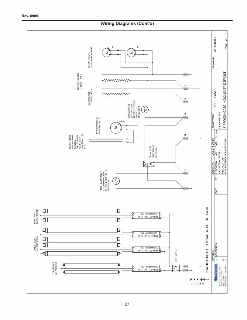
Rev. 0909
27
Wiring Diagrams (Cont'd)
DA
TE:
PRO
JECT
TIT
LE:
DRA
WIN
G #
:D
RAW
N B
Y:
PRO
DU
CTIO
N O
RDER
#:
DRA
WIN
G T
ITLE
:D
ATE
:RE
VISI
ON
S:#:
D
ESCR
IPTI
ON
:CH
ECKE
D B
Y:BY
:
FILE
LO
CATI
ON
:
AD
RIA
N E
. CRI
SCI
AEC
PAG
E
OF
Hus
sman
n Co
rpor
atio
n, In
t'l.
1377
0 Ra
mon
a A
venu
eCh
ino,
CA
. 917
10(9
09)-5
90-4
910
L
ic.#
: 644
406
11
07/1
3/01
1 2 3H
:\WIR
ESCH
EMA
TICS
\NEW
-WIR
ING
ASC
-L C
ASE
SW
0150
012
8' F
ROZE
N C
ASE
- KO
OLG
AS™
DEF
ROST
BALLAST 125-01-3266FULHAM LH3-120-L
L1 L2 L3 N G
L
LED
GE
LIG
HTS
(2) F
P28T
5/83
0
BALLAST 125-01-3266FULHAM LH3-120-L
BALLAST 125-01-3266FULHAM LH3-120-L
CAN
OPY
LIG
HTS
(4) F
32T8
-SPX
30N
OSE
LIG
HTS
(2) F
32T8
-SPX
30
AiR
SW
EEP
FAN
S(2
) 4½
" AXI
AL
MO
TORS
LIG
HT
SWIT
CH
REA
R CH
AN
NEL
WA
RMER
WIR
ERA
YCH
EM10
BUT-
CR-1
0W12
5-01
-076
710
W/F
T@~1
15V
8 FT
.
DRA
IN H
EATE
R(1
) 240
W /
~11
5 V
POW
ER R
EQU
IRED
: ~1
15 V
AC -
60 H
z. -
1Ø -
3 W
IRE
BALLAST 125-01-3266FULHAM LH3-120-L
DEL
AY
RELA
YM
ARS
902
49Q
225-
01-2
045
M
MM
EVA
PORA
TOR
FAN
(1) G
E 9W
- ~1
15V
AIR
SW
EEP
HEA
TER
(1) 2
40W
/ ~1
15 V
FAN
& H
EATE
R D
ELA
YKL
IXO
N T
HER
MO
DIS
K3N
T-01
F-D
1460
F35
-15
225-
01-2
046
DRA
IN H
EATE
RSA
FETY
KLI
XON
2042
0D42
-452
-362
L48-
1860
0-22
-005
0
IJ1
NJ2
J3N
I

IGSF-ASC-L/ASCS-L-0909
28
Wiring Diagrams (Cont'd)
DA
TE:
PR
OJE
CT
TITL
E:
DR
AW
ING
#:
DR
AW
N B
Y:
PR
OD
UCT
ION
OR
DE
R #
:D
RA
WIN
G T
ITLE
:D
ATE
:R
EVI
SIO
NS:
#:
DE
SC
RIP
TIO
N:
CH
EC
KE
D B
Y:
BY:
FILE
LO
CAT
ION
:D.Q
UA
N--
-
PAG
E
OF
Hus
sman
n C
orpo
ratio
n, In
t'l.
1377
0 R
amon
a A
venu
eC
hino
, CA
. 917
10(9
09)-
590-
4910
L
ic.#
: 644
406
11
07/1
3/01
1 2 3F:
\WIR
ES
CH
EMA
TIC
S\N
EW-W
IRIN
G
AS
C-L
CA
SE
SW
0150
014
12' F
RO
ZEN
CA
SE
- K
OO
LGA
S™
DE
FRO
ST
BALLAST 125-01-3266FULHAM LH3-120-L
L1 L2 L3 N G
L
FAN
MO
TOR
(2)1
25-0
1-06
15A
LIG
HT
SWIT
CH
RE
AR C
HA
NN
ELW
ARM
ER W
IRE
RA
YCH
EM10
BUT-
CR
-10W
125-
01-0
767
10W
/FT@
~115
V8
FT.
DR
AIN
HEA
TER
(1) 4
00W
/ ~1
15 V
125-
01-3
026
~115
VAC
- 60
Hz.
- 1Ø
BALLAST 125-01-3266FULHAM LH3-120-L
DEL
AY R
ELA
YM
ARS
9024
9Q22
5-01
-204
5
M
MM
EVA
PO
RA
TOR
FA
N(1
) GE
9W
- ~1
15V
0000
1212
AIR
SW
EEP
HE
ATE
R(2
) 180
W /
~115
V12
5-01
-303
2FA
N &
HE
ATER
DE
LAY
KLI
XON
TH
ER
MO
DIS
K3N
T-01
F-D
1460
F35
-15
OPE
N 3
5 F
CLO
SE 2
0 F
225-
01-2
046
DR
AIN
HE
ATER
SAF
ETY
KLI
XON
2042
0D42
-452
-362
L48-
18O
PEN
48
FC
LOSE
30
F60
0-22
-005
0
IJ1
IN
3J2J
N
BALLAST 125-01-3266FULHAM LH3-120-L
BALLAST 125-01-3266FULHAM LH3-120-L
F25T8-36"125-03-0010G
F25T8-36"125-03-0010GF25T8-36"125-03-0010G
F25T8-36"125-03-0010G
F25T8-36"125-03-0010G
F25T8-36"125-03-0010G
F21T5-36"125-03-1129F21T5-36"125-03-1129
LED
GE
LIG
HTS
CAN
OP
YLI
GH
TS
NO
NC
13
564
2

rev. 0909
�9
appendix a. - temperature guidelinesThe refrigerators should be operated according to the manufacturer’s published engineering specifications for entering air temperatures for specific equipment applications. Table 1 shows the typical temperature of the air entering the food zone one hour before the start of defrost and one hour after defrost for various categories of refrigerators. Refer to Appendix C for Field Evaluation Guidelines.
table 1
type of refrigerator typical entering air temperature
I. OPEN DISPLAY A. Non frozen: 1) Meat �8°F �) Dairy/Deli 3�°F 3) Produce a. Processed 36°F b. Unprocessed 45°F B. Frozen 0°F C. Ice Cream -5°FII. CLOSED DISPLAY A. Non frozen: 1) Meat 34°F �) Dairy/Deli 34°F 3) Produce a. Processed 36°F b. Unprocessed 45°F B. Frozen 0°F C. Ice Cream -5°F
Single Deck Multi Deck Service Case Reach-In I. Open Display Styles II. Closed Display Styles
appendix B. - application recommendations1.0 Temperature performance is critical for controlling
bacteria growth. Therefore, the following recommendations are included in the standard. They are based on confirmed field experience over many years.
1.1 The installer is responsible for following the installation instructions and recommendations provided by Hussmann for the installation
of each individual type refrigerator.1.� Refrigeration piping should be sized according to
the equipment manufacturer’s recommendations and installed in accordance with normal refrigeration practices. Refrigeration piping should be insulated according to Hussmann’s recommendations.
1.3 A clogged waste outlet blocks refrigeration. The installer is responsible for the proper installation of the system which dispenses condensate waste through an air gap into the building indirect waste system.
1.4 The installer should perform a complete start-up evaluation prior to the loading of food into the refrigerator, which includes such items as: a) Initial temperature performance, Coils should
be properly fed with a refrigerant according to manufacturer’s recommendations.
b) Observation of outside influences such as drafts, radiant heating from the ceiling and from lamps. Such influence should be properly corrected or compensated for.
c) At the same time, checks should be made of the store dry-bulb and wet-bulb temperatures to ascertain that they are within the limits prescribed by Hussmann.
d) Complete start-up procedures should include checking through a defrost to make certain of its adequate frequency and length without substantially exceeding the actual needs. This should include checking the electrical or refrigerant circuits to make sure that defrosts are correctly programmed for all the refrigerators connected to each refrigeration system.
e) Recording instruments should be used to check performance.
appendix c. - field recommendationsRecommendations for field evaluating the performance of retail food refrigerators and hot cases1.0 The most consistent indicator of display
refrigerator performance is temperature of the air entering the product zone (see Appendix A). In practical use, the precise determination of return air temperature is extremely difficult. Readings of return air temperatures will be variable and results will be inconsistent. The product temperature alone is not an indicator of refrigerator performance.
note: public health will use the temperature of the product in determining if the refrigerator will be allowed to display potentially hazardous food. for the purpose of this evaluation, product temperature above the fda food code 1993 temperature for potentially hazardous food will be the first indication that an evaluation should be performed. it is expected that all refrigerators will keep food at the fda food code 1993 temperature for potentially hazardous food.
appendices

igsf-asc-l/ascs-l-0909
30
1.1 The following recommendations are made for the purpose of arriving at easily taken and understood data which, coupled with other observations, may be used to determine whether a display refrigerator is working as intended:a) INSTRUMENT - A stainless steel stem-type
thermometer is recommended and it should have a dial a minimum of 1 inch internal diameter. A test thermometer scaled only in Celsius or dually scaled in Celsius and Fahrenheit shall be accurate to 1°C (1.8°F). Temperature measuring devices that are scaled only in Fahrenheit shall be accurate to �°F. The thermometer should be checked for proper calibration. (It should read 3�°F when the stem is immersed in an ice water bath).
b) LOCATION - The probe or sensing element of the thermometer should be located in the airstream where the air first enters the display or storage area, and not more than 1 inch away from the surface and in the center of the discharge opening.
c) READING - It should first be determined that the refrigerator is refrigerating and has operated at least one hour since the end of the last defrost period. The thermometer reading should be made only after it has been allowed to stabilize, i.e., maintain a constant reading.
d) OTHER OBSERVATIONS - Other observations should be made which may indicate operating problems, such as unsatisfactory product, feel/appearance.
e) CONCLUSIONS - In the absence of any apparent undesirable conditions, the refrigerator should be judged to be operating properly. If it is determined that such condition is undesirable, i.e., the product is above proper temperature, checks should be made for the following:1. Has the refrigerator been loaded with
warm product?�. Is the product loaded beyond the “Safe
Load Line” markers?3. Are the return air ducts blocked?4. Are the entering air ducts blocked?5. Is a dumped display causing turbulent air
flow and mixing with room air?6. Are spotlights or other high intensity
lighting directed onto the product?7. Are there unusual draft conditions (from
heating/air-conditioning ducts, open doors, etc.)?
8. Is there exposure to direct sunlight?9. Are display signs blocking or diverting
airflow?10. Are the coils of the refrigerator iced up?11. Is the store ambient over 75°F, 55% RH
as set forth in ASHRAE Standard 7� and ASHRAE Standard 117?
1�. Are the shelf positions, number, and size other than recommended by Hussmann?
13. Is there an improper application or control system?
14. Is the evaporator fan motor/blade inoperative?
15. Is the defrost time excessive?16. Is the defrost termination, thermostat (if
used) set too high?17. Are the refrigerant controls incorrectly
adjusted?18. Is the air entering the condenser above
design conditions? Are the condenser fins clear of dirt, dust, etc.?
19. Is there a shortage of refrigerant?20. Has the equipment been modified
to use replacements for CFC-1�, CFC-50� or other refrigerant? If so, have the modifications been made in accordance with the recommendations of the equipment manufacturer? Is the refrigerator charged with the proper refrigerant and lubricant? Does the system use the recommended compressor?
appendix d. - recommendations to user1.0 Hussmann Corporation provides instructions
and recommendations for proper periodic cleaning. The user will be responsible for such cleaning, including the cleaning of low temperature equipment within the compartment and the cooling coil area(s). Cleaning practices, particularly with respect to proper refrigerator unloading and warm-up, must be in accordance with applicable recommendations.
appendices (cont'd)

rev. 0909
31
1.1 Cleaning of non frozen food equipment should include a weekly cleaning of the food compartment as a minimum to prevent bacteria growth from accumulating. Actual use and products may dictate more frequent cleaning. Circumstances of use and equipment design must also dictate the frequency of cleaning the display areas. Weekly washing down of the storage compartment is also recommended, especially for equipment subject to drippage of milk or other liquids, or the collection of vegetable, meat, crumbs, etc. or other debris or litter. Daily cleaning of the external areas surrounding the storage or display compartments with detergent and water will keep the equipment presentable and prevent grime buildup.
1.2 Load levels as defined by the manufacturer must be observed.
1.3 The best preservation is achieved by following these rules:a) Buy quality products.b) Receive perishables from transit equipment
at the ideal temperature for the particular product.
c) Expedite perishables to the store’s storage equipment to avoid unnecessary warm-up and prolonged temperature recovery. Food store refrigerators are not food chillers nor can they reclaim quality lost through previous mishandling.
d) Care must be taken when cross merchandising products to ensure that potentially hazardous vegetable products are not placed in non refrigerated areas.
e) Display and storage equipment doors should be kept closed during periods of inactivity.
f) Minimize the transfer time of perishables from storage to display.
g) Keep meat under refrigeration in meat cutting and processing area except for the few moments it is being handled in processing. When a cut or tray of meat is not to be worked on immediately, the procedure should call for returning it to refrigeration.
h) Keep tools clean and sanitized. Since mechanical equipment is used for fresh meat processing, all such equipment should be cleaned at least daily and each time a different kind of meat product comes in contact with the tool or equipment.
i) Make sure that all refrigeration equipment is installed and adjusted in strict accordance with the manufacturer’s recommendations.
j) See that all storage and refrigeration equipment is kept in proper working order by routine maintenance.
appendices (cont'd)

The MODEL NAME and SERIAL NUMBER is required in order to provide you with the correct parts and information for your particular unit.
They can be found on a small metal plate on the unit.Please note them below for future reference.
model:
serial numBer:
/ChinoAdditional copies of this publication may be obtained by contacting:
Hussmann® Chino 13770 Ramona Avenue • Chino, California 91710(909) 6�8-894� FAX(909) 590-4910 (800) 395-9��9
service recordlast service date: By:
_______________ __________________________________________________________________________________________________
_______________ __________________________________________________________________________________________________
_______________ __________________________________________________________________________________________________
_______________ __________________________________________________________________________________________________
_______________ __________________________________________________________________________________________________
_______________ __________________________________________________________________________________________________
_______________ __________________________________________________________________________________________________
igsf-asc-l/ascs-l-0909