chinese wok range owner s manual section 1 ......
TRANSCRIPT

CHINESE WOK RANGE OWNER’S MANUAL
SECTION 1 INSTALLATION INSTRUCTIONS
When sold in the Commonwealth of Massachusetts this unit must be equipped with an interlock to prevent operation only if the hood system is operational. Installation of the interlock is the responsibility of the installer—it is not supplied by the factory.
WARNINGImproper installation, adjustment, alteration, service or maintenance can cause property damage, injury or death.
Read the installation, operating and maintenance instructions thoroughly before installing or servicing this equipment.
FOR YOUR SAFETYDo not store or use gasoline or other fl ammable vapors and liquids in the vicinity of this or any other appliance.
IMPORTANTContact your local gas supplier for instructions if you smell gas near this equipment.
FOR COMMERCIAL USE ONLY
© Town Food Service Equipment Company, Inc. No part of this booklet or it ’s illustrations may be copied or reproduced without written authorization from Town Food Service Equipment Co., Inc.
6/14
DO NOT DISCARD INSTRUCTIONS. THIS MANUAL MUST REMAIN WITH THE UNIT FOR FUTURE REFERENCE.THIS EMERGENCY INFORMATION MUST BE PROMINENTLY DISPLAYED.

Town Food Service Equipment Company, Inc. 718/388-5650 outside New York State 800/221-5032
2
A REMOVABLE FLUE RISER CAPB BACK SPLASHC SWING FAUCET D 3 PIPE WOK COVER/STRAINER RACKE MANUAL FAUCETF SIDE SPLASH G MANDARIN CHAMBER RING
H CANTONESE CHAMBER RINGI PLATE SHELF J WATER WASH CONTROL VALVEK DRIP TRAYL PILOT LIGHT CONTROL VALVE M KNEE OPERATED GAS VALVESN FRONT ACCESS SINK (WASTE) BASKET
YORK AND MASTERRANGE PARTS IDENTIFICATION
A
B
G
J
I
E
F
K
H
D
L
MN
C
__________________________________________________________________________________________________________________________________________________________________

EF-1
E-1
YF-1
Y-1
MF-1
M-1
Town Food Service Equipment Company, Inc. 718/388-5650 outside New York State 800/221-5032
3
POSITIONING1) Position crate in approximate location that the unit will occupy. Uncrate range and locate sealed cartons on the range top containing the following accessories: (1) set of adjustable legs or casters if ordered; (1) drip pan for each chamber; (1) extension chimney for each opening in return splash if your unit is equipped with a fl ue riser; and (1) gas pressure regulator. Find the legs and set one leg by each range gusset into which it will be inserted. Raise 1 end of the unit at a time; insert legs; and tighten set screws with ¼” Allen wrench. If your range has fl ue risers, slip the extension chimney over each riser.
2) Range is now ready for fi nal positioning. Carefully lift range into desired position to avoid damage to adjustable legs. Clearances from combustible construction are 6” at rear and sides. Remove burner tie wires and other packing materials. Check gas burners that may have shifted in transit and center them by eye if required. Turn all gas valve lever handles to off (horizontal) position. Check air mixer alignment to gas burner nipple and tighten set screws if necessary.
3) Clearances for noncombustible construction are the same as combustible clearances. This range is for installation only on noncombustible fl oors.
INSTALLATION• The gas supply line must be of adequate size to ensure maximum effi ciency of the unit.
• The installation must conform with the National Fuel Gas Code, ANSI Z223.1, Natural Gas Installation Code, CAN/CGA-B149.1 or the Propane Installation Code, CAN/CGA-B149.2, as applicable, including: a) The appliance and its individual shutoff valve must be disconnected from the gas supply piping system during any pressure testing of that system at test pressures in excess of 1/ 2 PSI (3.45 kPa).
b) The appliance must be isolated from the gas supply piping system by closing its individual manual valve during any pressure testing of the gas supply piping system at test pressures equal or less than 1/ 2 PSIG (3.45 kPa).
• Local regulations governing gas appliance installations must be complied with.
• Equipment should be under hood with adequate ventilation.
STOCKPOT AND WOK TOP RANGE INSTALLATION INSTRUCTIONS__________________________________________________________________________________________________________________________________________________FOLLOW THESE INSTRUCTIONS CAREFULLY INSTALLATION AREA MUST BE FREE AND CLEAR FROM COMBUSTIBLES
CONGRATULATIONS ON YOUR PURCHASE OF A ECODECK, YORK OR MASTERRANGE WOK RANGE
It will give you many years of trouble free use if it is properly used and maintained. Please call our customer service department at 718/388-5650 if you have questions regarding equipment operation or care.
Your range has been carefully engineered and constructed with the best possible workmanship and materials to provide many years of satisfactory service. Proper installation is vital if best appearance and performance is to be achieved.
Town Food Service Equipment Company, Inc. 718/388-5650 outside New York State 800/221-5032
4
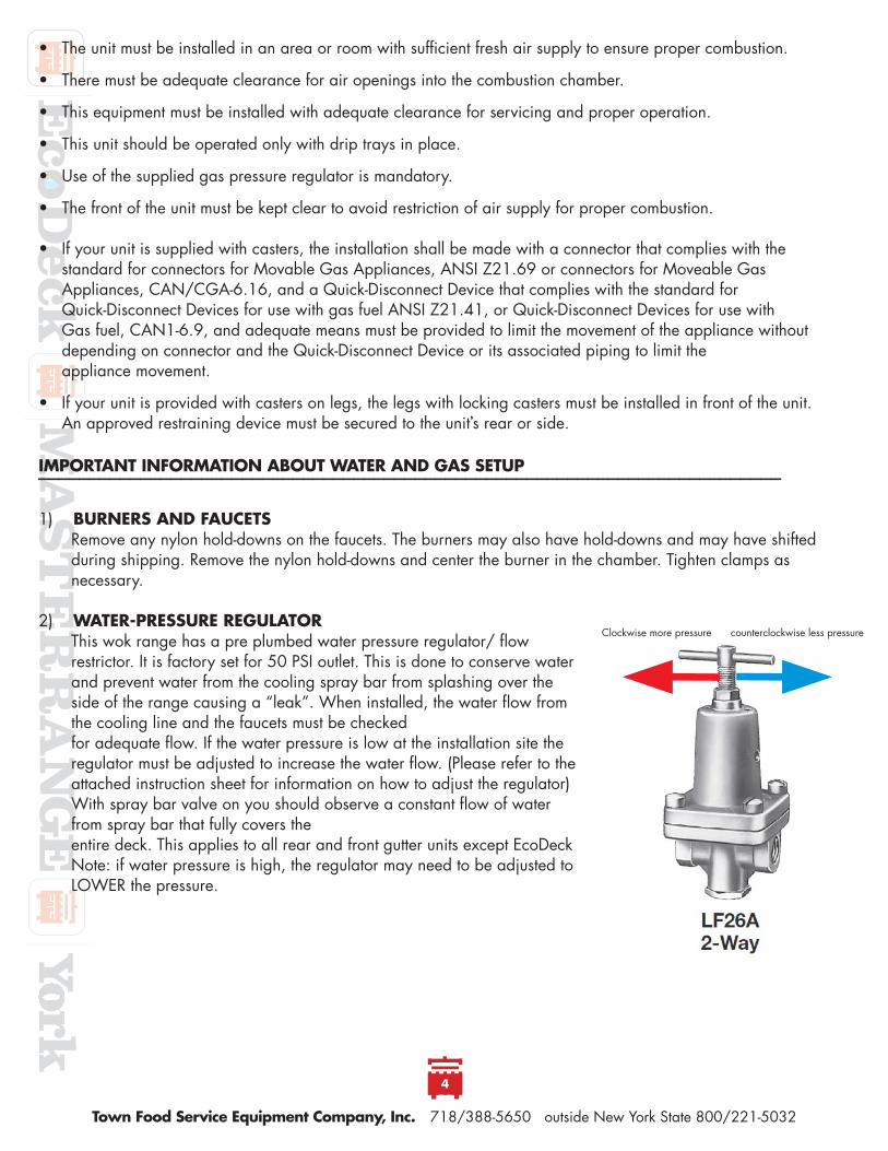
• The unit must be installed in an area or room with suffi cient fresh air supply to ensure proper combustion.
• There must be adequate clearance for air openings into the combustion chamber.
• This equipment must be installed with adequate clearance for servicing and proper operation.
• This unit should be operated only with drip trays in place.
• Use of the supplied gas pressure regulator is mandatory.
• The front of the unit must be kept clear to avoid restriction of air supply for proper combustion.
• If your unit is supplied with casters, the installation shall be made with a connector that complies with thestandard for connectors for Movable Gas Appliances, ANSI Z21.69 or connectors for Moveable GasAppliances, CAN/CGA-6.16, and a Quick-Disconnect Device that complies with the standard for Quick-Disconnect Devices for use with gas fuel ANSI Z21.41, or Quick-Disconnect Devices for use with Gas fuel, CAN1-6.9, and adequate means must be provided to limit the movement of the appliance withoutdepending on connector and the Quick-Disconnect Device or its associated piping to limit the appliance movement.
• If your unit is provided with casters on legs, the legs with locking casters must be installed in front of the unit. An approved restraining device must be secured to the unit’s rear or side.
1) BURNERS AND FAUCETSRemove any nylon hold-downs on the faucets. The burners may also have hold-downs and may have shifted during shipping. Remove the nylon hold-downs and center the burner in the chamber. Tighten clamps as necessary.
2) WATER-PRESSURE REGULATORThis wok range has a pre plumbed water pressure regulator/ fl ow restrictor. It is factory set for 50 PSI outlet. This is done to conserve water and prevent water from the cooling spray bar from splashing over the side of the range causing a “leak”. When installed, the water fl ow from the cooling line and the faucets must be checkedfor adequate fl ow. If the water pressure is low at the installation site the regulator must be adjusted to increase the water fl ow. (Please refer to the attached instruction sheet for information on how to adjust the regulator) With spray bar valve on you should observe a constant fl ow of water from spray bar that fully covers theentire deck. This applies to all rear and front gutter units except EcoDeckNote: if water pressure is high, the regulator may need to be adjusted to LOWER the pressure.
3
IMPORTANT INFORMATION ABOUT WATER AND GAS SETUP__________________________________________________________________________________________________________________________________________________
Clockwise more pressure counterclockwise less pressure

EF-1
E-1
YF-1
Y-1
MF-1
M-1
Town Food Service Equipment Company, Inc. 718/388-5650 outside New York State 800/221-5032
5
3) WATER AND DRAINCheck that all faucets work. If it is a Chinese style swing faucet, move the faucet perpendicular to the backsplash to check for water fl ow. Turn on the water wash and verify that water fl ows and washes the entire deck surface. Verify that the water fl ow covers the entire top deck and the backsplash- if a front gutter, waterfall backsplash
design. Level as necessary to ensure even water fl ow across the deck by adjusting bullet legs to position and control pitch of deck. Refer to item # 2 if water fl ow needs to be adjusted due to pressure.
4) PILOTSAfter the unit has been connected by the licensed plumber and has passed local inspection, turn gas on and light all of the pilots. In a standing pilot, light each pilot and adjust fl ame using the pilot gas valve supplied for each chamber. The pilot valve is the small brass fi tting with a small brass hex screw and is located on each manifold burner gas riser. Using a jeweler’s screwdriver, turn clockwise to decrease the fl ame and counter clockwise to increase the fl ame. Do not remove the screw. If a safety pilot, there will be a small control in the front panel for each chamber with a red button. Follow the instructions in the owner’s manual for startup using safety pilots. The burners will not light if the safety pilots are not lit fi rst.
5) PILOT SAFETY SYSTEMThe Pilot safety system utilizes a thermocouple. The thermocouple connection must be clean and tight. This unit is shipped with the thermocouple(s) connected and properly tightened. Connection cannot be too tight or the grey bulb (positive connection) will break off. Check that the grey bulb is free of corrosion, clean with fi ne grit sandpaper if necessary. Hand tighten the hex fi tting, then using a wrench tighten the hex nut an additional ¼ turn clockwise. If you over tighten the hex nut the bulb will break off.
6) GAS REGULATORThe supplied appliance regulator has a maximum continuous rated input of 15” WC (approx. 0.5psig). The supplied regulator must be installed on all Town wok ranges. Do not overpressure the regulator. If your natural gas system is a 2-5 PSI system you need to have a 1st stage line regulator (supplied by others) installed upstream of our appliance
7) GAS FEED If the manifold piping and fi nal connection piping are not properly sized the equipment will not function at optimal levels. Consult with your plumber or LPE to insure that the pipe sizing is correct. We do not recommend Flex type (quick disconnect) hoses for use with the woks. If selected, the fl ex should be sized to fl ow the rated gas input capacity. The maximum fl ex hose length should be 36” and be without any swivel connectors.

Town Food Service Equipment Company, Inc. 718/388-5650 outside New York State 800/221-5032
6
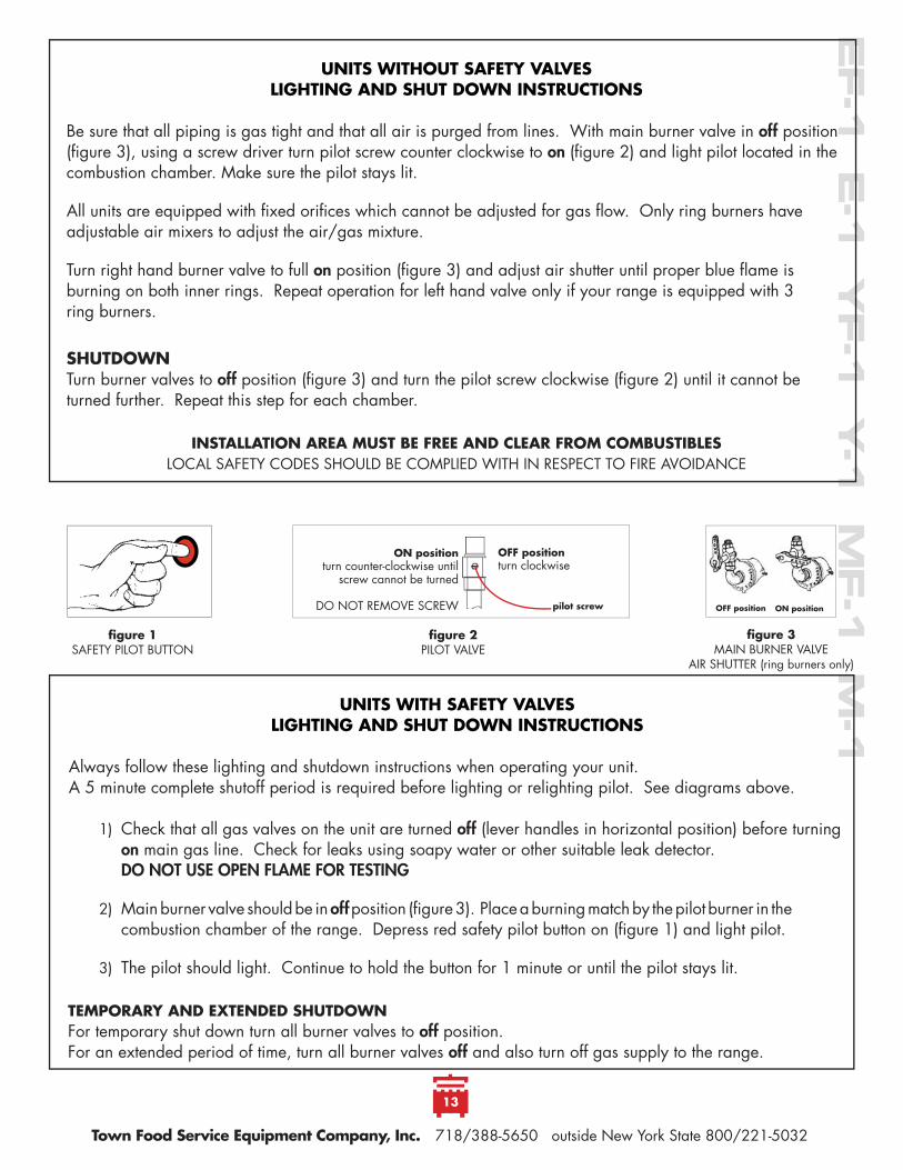
fi gure 2 PILOT VALVE
fi gure 1SAFETY PILOT BUTTON
put lit match to pilot burner, depress and
hold red button
UNITS WITH SAFETY VALVESLIGHTING AND SHUT DOWN INSTRUCTIONS
Always follow these lighting and shutdown instructions when operating your unit. A 5 minute complete shutoff period is required before lighting or relighting pilot. See diagrams above.
1) Check that all gas valves on the unit are turned off (lever handles in horizontal position) before turning on main gas line. Check for leaks using soapy water or other suitable leak detector. DO NOT USE OPEN FLAME FOR TESTING
2) Main burner valve should be in off position (fi gure 3). Place a burning match by the pilot burner in the combustion chamber of the range. Depress red safety pilot button on (fi gure 1) and light pilot.
3) The pilot should light. Continue to hold the button for 1 minute or until the pilot stays lit.
TEMPORARY AND EXTENDED SHUTDOWNFor temporary shut down turn all burner valves to off position. For an extended period of time, turn all burner valves off and also turn off gas supply to the range.
ON positionturn clockwise
until screw cannot be turned
OFF positionturn counter-clockwise
pilot screwOFF positionON position
UNITS WITHOUT SAFETY VALVESLIGHTING AND SHUT DOWN INSTRUCTIONS
Be sure that all piping is gas tight and that all air is purged from lines. With main burner valve in off position (fi gure 3), using a screw driver turn pilot screw counter clockwise to on (fi gure 2) and light pilot located in the combustion chamber. Make sure the pilot stays lit.
All units are equipped with fi xed orifi ces which cannot be adjusted for gas fl ow. Only ring burners have adjustable air mixers to adjust the air/gas mixture.
Turn right hand burner valve to full on position (fi gure 3) and adjust air shutter until proper blue fl ame is burning on both inner rings. Repeat operation for left hand valve only if your range is equipped with 3 ring burners.
SHUTDOWNTurn burner valves to off position (fi gure 3) and turn the pilot screw clockwise (fi gure 2) until it cannot be turned further. Repeat this step for each chamber.
INSTALLATION AREA MUST BE FREE AND CLEAR FROM COMBUSTIBLES LOCAL SAFETY CODES SHOULD BE COMPLIED WITH IN RESPECT TO FIRE AVOIDANCE
AIR SHUTTER(ring burners only)
fi gure 3MAIN BURNER VALVE
4

EF-1
E-1
YF-1
Y-1
MF-1
M-1
Town Food Service Equipment Company, Inc. 718/388-5650 outside New York State 800/221-5032
7
gutter
Some installations require the backsplash to be removed so the range can fi t through a 34” door. Town ranges are manufactured with removable backsplashes. Follow these steps to remove backsplash:
1) Loosen union at backsplash (fi gure 1).
2) Remove sidesplash bolts and lower backsplash (fi gure 2).
3) Faucet manifold must be placed below gutter (fi gure 3)
4) Lower backsplash until sidesplash clears gutter (fi gure 4).
5) Sidesplash may be removed. Range will fi t through 34” opening (fi gure 5).
6) Reinsert sidesplash and backsplash into gutter. Ensure backsplash “J” hooks in to the gutter “J” (fi gure 6).
7) Raise backsplash, making sure it is locked into the gutter “J” (fi gure 7).
8) When raised, the gutter and backsplash should be aligned. Bolt side splashes to body (fi gure 8).
fi gure 1
fi gure 4
fi gure 7
fi gure 6
fi gure 8
fi gure 3
gutter “J”
fi gure 5
fi gure 2
backsplash “J”
faucetmanifold
gutter
BACKSPLASH REMOVAL AND REINSTALLATION__________________________________________________________________________________________________________________________________________________________________

Town Food Service Equipment Company, Inc. 718/388-5650 outside New York State 800/221-5032
8
Ranges with optional Flue Risers have stainless steel extensions that cover the tops of the fl ue risers. Locate the parts in the boxed marked “RANGE ACCESSORIES”.
1) Take assembled fl ue collar and turn with kink to rear (fi gure A).
2) Place fl ue collar on top of chimney extension as illustrated (fi gure B).
3) Catch front return beneath slot in backsplash (circled in fi gure C).
4) Snap kinked end into slot (fi gure D).
fi gure 1 fi gure 2
The optional fi eld joint joins two or more ranges. It must be ordered when the ranges are built. It cannot be added to existing ranges. A butt fi eld joint has a standing seam between ranges while a splice fi eld joint gives a smooth fi t.
Each range has a vertical seam at the joint between the ranges. The backsplashes will be joined.
1) Uncrate the ranges and install legs onto the gussets. Secure legs with the gusset set screw.
2) Carefully locate the battery into fi nal location. Align the sides to be joined. The battery was assembled at the factory to assure good fi t. Pitched fl oors will add diffi culty to battery assembly (fi gures 1 and 2).
3) Align the backsplashes. It may necessary to level the range so the backsplashes meet at top. Insert and slide down the “U” shaped joiner until it is level with the top of the backsplash (fi gures 3 and 4).
fi gure C fi gure Dfi gure Bfi gure AKINK
FLUE RISER EXTENSION INSTALLATION (NEW VERSION ON UNITS SHIPPED AFTER JUNE 2005)__________________________________________________________________________________________________________________________________________________________________
FIELD JOINT INSTALLATIONS__________________________________________________________________________________________________________________________________________________________________
BUTT FIELD JOINT INSTALLATION INSTRUCTIONS__________________________________________________________________________________________________________________________________________________________________

EF-1
E-1
YF-1
Y-1
MF-1
M-1
Town Food Service Equipment Company, Inc. 718/388-5650 outside New York State 800/221-5032
9
4) Install the stainless tubular wok cover rack. Male and female ends mate to become a continuous length. Remove the bolts from the brackets and install the tubing with threaded ends. Use the bolts removed from the brackets at the endsplashes. (fi gures 5, 6 and 7).
5) The range position may have to be adjusted to align the bolt holes in the serving shelf with the tapped holes provided for them (fi gures 8 and 9).
6) Pitch the range using the adjustable bullet feet so that water fl ows off the top of the range.
7) Connections can be made by authorized personnel. Each range has gas, waste and water connections.
fi gure 9
fi gure 4
fi gure 8
fi gure 3
fi gure 5
fi gure 7
fi gure 6

Town Food Service Equipment Company, Inc. 718/388-5650 outside New York State 800/221-5032
10
fi gure 1
fi gure 2
fi gure 3
Range decks have a “tongue and groove” so there is no standing seam between range decks. The decks and backsplashes are joined. The gutters are separate but interlock.
1) Uncrate the ranges and place them on pallet jacks. Be careful to position jacks away from drip pan guides.
2) Install the legs onto each range. Secure legs with the set screw in the gusset.
3) Remove the front body panels. Figure 1 shows a detail of front right corner of a range with the
body front panel removed.
4) Carefully move the ranges to their fi nal location. Position the ends to be joined next to each other. The battery was assembled at the factory to assure good fi t. Pitched fl oors will add diffi culty to battery assembly.
5) Generously apply silicon to the groove below the stainless steel deck. Apply additional silicon to the
tongue of the other range that will fi t into this groove. Figure 2 shows the groove.
6) Insert the tongue into the groove and slide the ranges together as shown in fi gure 3.
7) Be certain that the range with an extension on its gutter overlaps the gutter of the adjoining range as
shown in fi gure 4.
8) Locate the bolt holes in the range body as shown above in fi gures 4 and 5 and bolt the range bodies together.
9) Silicon the front seam of range decks in the circled area of fi gure 6.
10) Align the backsplashes. It may necessary to level the range so the backsplashes meet at top. Insert and slide down the “U” shaped joiner until it is level with the top of the backsplash. See fi gures 7 and 8.
11) Install the three stainless steel tubes of the wok cover rack. Note—there are male and female ends that mate to become a continuous length.
12) Pitch the range using the adjustable bullet feet so that water fl ows off the top of the range.
8
SPLICE FIELD JOINT INSTALLATION INSTRUCTIONS__________________________________________________________________________________________________________________________________________________________________SPLICE FIELD JOINT INSTALLATION INSTRUCTIONS__________________________________________________________________________________________________________________________________________________________________

EF-1
E-1
YF-1
Y-1
MF-1
M-1
Town Food Service Equipment Company, Inc. 718/388-5650 outside New York State 800/221-5032
11
fi gure 8
fi gure 9
fi gure7fi gure 4
fi gure 5
fi gure 6
9

CHINESE WOK RANGE OWNER’S MANUALSECTION 2 OPERATING
AND MAINTENANCE INSTRUCTIONS
When sold in the Commonwealth of Massachusetts this unit must be equipped with an interlock to prevent operation only if the hood system is operational. Installation of the interlock is the responsibility of the installer—it is not supplied by the factory.
WARNINGImproper installation, adjustment, alteration, service or maintenance can cause property damage, injury or death.
Read the installation, operating and maintenance instructions thoroughly before installing or servicing this equipment.
FOR YOUR SAFETYDo not store or use gasoline or other fl ammable vapors and liquids in the vicinity of this or any other appliance.
IMPORTANTContact your local gas supplier for instructions if you smell gas near this equipment.
© Town Food Service Equipment Company, Inc. No part of this booklet or it ’s illustrations may be copied or reproduced without written authorization from Town Food Service Equipment Co., Inc.
2/13
DO NOT DISCARD INSTRUCTIONS. THIS MANUAL MUST REMAIN WITH THE UNIT FOR FUTURE REFERENCE.THIS EMERGENCY INFORMATION MUST BE PROMINENTLY DISPLAYED.
EF-1
E-1
YF-1
Y-1
MF-1
M-1
Town Food Service Equipment Company, Inc. 718/388-5650 outside New York State 800/221-5032
13
fi gure 2 PILOT VALVE
fi gure 1SAFETY PILOT BUTTON
UNITS WITH SAFETY VALVESLIGHTING AND SHUT DOWN INSTRUCTIONS
Always follow these lighting and shutdown instructions when operating your unit. A 5 minute complete shutoff period is required before lighting or relighting pilot. See diagrams above.
1) Check that all gas valves on the unit are turned off (lever handles in horizontal position) before turning on main gas line. Check for leaks using soapy water or other suitable leak detector. DO NOT USE OPEN FLAME FOR TESTING
2) Main burner valve should be in off position (fi gure 3). Place a burning match by the pilot burner in the combustion chamber of the range. Depress red safety pilot button on (fi gure 1) and light pilot.
3) The pilot should light. Continue to hold the button for 1 minute or until the pilot stays lit.
TEMPORARY AND EXTENDED SHUTDOWNFor temporary shut down turn all burner valves to off position. For an extended period of time, turn all burner valves off and also turn off gas supply to the range.
ON positionturn counter-clockwise until
screw cannot be turned
DO NOT REMOVE SCREW
OFF positionturn clockwise
pilot screw ON positionOFF position
UNITS WITHOUT SAFETY VALVESLIGHTING AND SHUT DOWN INSTRUCTIONS
Be sure that all piping is gas tight and that all air is purged from lines. With main burner valve in off position (fi gure 3), using a screw driver turn pilot screw counter clockwise to on (fi gure 2) and light pilot located in the combustion chamber. Make sure the pilot stays lit.
All units are equipped with fi xed orifi ces which cannot be adjusted for gas fl ow. Only ring burners have adjustable air mixers to adjust the air/gas mixture.
Turn right hand burner valve to full on position (fi gure 3) and adjust air shutter until proper blue fl ame is burning on both inner rings. Repeat operation for left hand valve only if your range is equipped with 3 ring burners.
SHUTDOWNTurn burner valves to off position (fi gure 3) and turn the pilot screw clockwise (fi gure 2) until it cannot be turned further. Repeat this step for each chamber.
INSTALLATION AREA MUST BE FREE AND CLEAR FROM COMBUSTIBLES LOCAL SAFETY CODES SHOULD BE COMPLIED WITH IN RESPECT TO FIRE AVOIDANCE
fi gure 3MAIN BURNER VALVE
AIR SHUTTER (ring burners only)
Town Food Service Equipment Company, Inc. 718/388-5650 outside New York State 800/221-5032
14
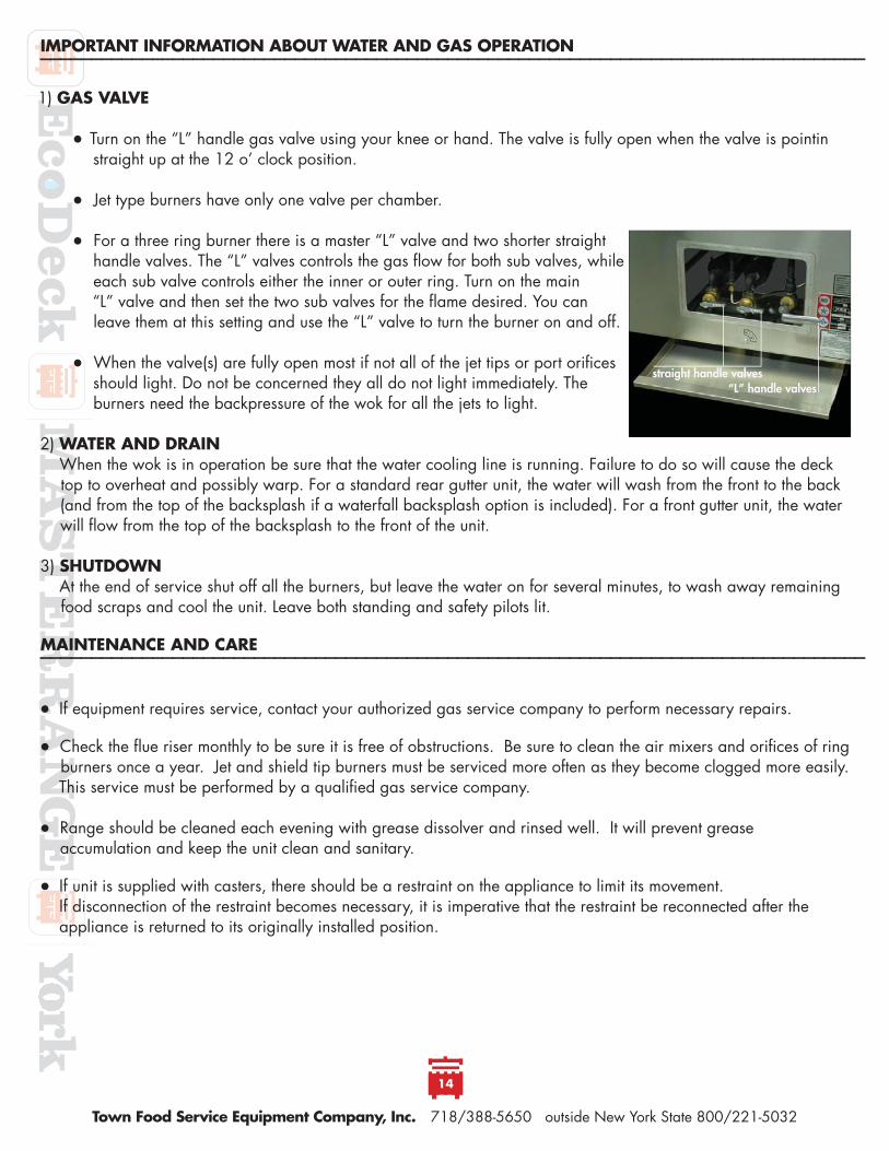
1) GAS VALVE
Turn on the “L” handle gas valve using your knee or hand. The valve is fully open when the valve is pointin straight up at the 12 o’ clock position.
Jet type burners have only one valve per chamber.
For a three ring burner there is a master “L” valve and two shorter straight handle valves. The “L” valves controls the gas fl ow for both sub valves, while each sub valve controls either the inner or outer ring. Turn on the main
“L” valve and then set the two sub valves for the fl ame desired. You can leave them at this setting and use the “L” valve to turn the burner on and off.
When the valve(s) are fully open most if not all of the jet tips or port orifi ces should light. Do not be concerned they all do not light immediately. The burners need the backpressure of the wok for all the jets to light.
2) WATER AND DRAINWhen the wok is in operation be sure that the water cooling line is running. Failure to do so will cause the deck top to overheat and possibly warp. For a standard rear gutter unit, the water will wash from the front to the back (and from the top of the backsplash if a waterfall backsplash option is included). For a front gutter unit, the water will fl ow from the top of the backsplash to the front of the unit.
3) SHUTDOWNAt the end of service shut off all the burners, but leave the water on for several minutes, to wash away remaining food scraps and cool the unit. Leave both standing and safety pilots lit.
If equipment requires service, contact your authorized gas service company to perform necessary repairs.
Check the fl ue riser monthly to be sure it is free of obstructions. Be sure to clean the air mixers and orifi ces of ring burners once a year. Jet and shield tip burners must be serviced more often as they become clogged more easily. This service must be performed by a qualifi ed gas service company.
Range should be cleaned each evening with grease dissolver and rinsed well. It will prevent grease accumulation and keep the unit clean and sanitary.
If unit is supplied with casters, there should be a restraint on the appliance to limit its movement. If disconnection of the restraint becomes necessary, it is imperative that the restraint be reconnected after the appliance is returned to its originally installed position.
IMPORTANT INFORMATION ABOUT WATER AND GAS OPERATION__________________________________________________________________________________________________________________________________________________________________
MAINTENANCE AND CARE__________________________________________________________________________________________________________________________________________________________________
“L” handle valvesstraight handle valves

EF-1
E-1
YF-1
Y-1
MF-1
M-1
Town Food Service Equipment Company, Inc. 718/388-5650 outside New York State 800/221-5032
15
12
MAINTENANCE AND CARE__________________________________________________________________________________________________________________________________________________________________THE FOLLOWING SERVICE SHOULD BE DONE ONLY BY A QUALIFIED GAS SERVICE TECHNICIAN
CHANGING THE PILOT LIGHT IN A CHAMBER WITH A RING BURNER OR SHIELD TIP BURNERShut off pilot valve. The pilot light is mounted on fl exible tubing and can be raised. Using a 12mm open-ended wrench, hold the center of the compression fi tting below the pilot fi rm.
Using a 1/2 ” wrench, unscrew the pilot from its brass fi tting at bottom. Install the new pilot by reversing the above procedure. Adjust the pilot fl ame at the pilot valve and be sure to check for gas leaks using a soapy solution.
CHANGING THE PILOT LIGHT IN A CHAMBER WITH A JET BURNERShut off pilot valve. Using a 12mm open-ended wrench, unscrew the pilot, remove and replace. If a 12mm open-ended wrench is unavailable, a 1/2 ” open end or adjustable wrench may suffi ce.
FLUE COLLAR REPLACEMENT (“F” MODELS)The cast iron fl ue collar may deteriorate after considerable use. If deterioration is detected, we suggest you contact your local service company for replacement parts and qualifi ed service. If you must replace the fl ue col-lar yourself, follow the instructions below:
SHUT OFF GAS TO RANGE BEFORE MAKING ANY ADJUSTMENTS THE BURNER AND PILOT MUST BE REMOVED BEFORE REMOVING THE FLUE COLLAR
1) Remove old nuts behind range that secure fl ue collar (1).
2) Remove worn collars with pry bar (2). Put new collar into place using provided hardware. Re-cement chamber and replace burner and pilot.
PILOT VALVE
PILOT
FLUE COLLAR
ON positionturn clockwise
until screw cannot be turned
OFF positionturn counter-clockwise
pilot screw

16
ROBERTSHAW PILOT SAFETY VALVE INFORMATION__________________________________________________________________________________________________________________________________________________________________

17
ROBERTSHAW PILOT SAFETY VALVE INFORMATION__________________________________________________________________________________________________________________________________________________________________

18
ROBERTSHAW PILOT SAFETY VALVE INFORMATION__________________________________________________________________________________________________________________________________________________________________

EF-1
E-1
YF-1
Y-1
MF-1
M-1
Town Food Service Equipment Company, Inc. 718/388-5650 outside New York State 800/221-5032
19
*please advise if chamber has a fl ue collar when ordering
ECODECK/YORK REPLACEMENT FIBER CERAMICSnumber fi ts chamber interior dimension
225014N __ 13” _________ 11” (6 lbs.)225016N __ 16” _________ 14” (7 lbs.)225118N __ 18” _________ 16” (8 lbs.)225020N __ 20” _________ 18” (9 lbs.)225022N __ 22” _________ 20” (12 lbs.)
REPLACEMENT MASTERRANGE FIRE BRICKS number description
225038 ____ 13” chamber brick set* (55 lbs.)225042 ____ 16” chamber brick set* (65 lbs.)225043 ____ 18” chamber brick set* (75 lbs.)225044 ____ 20” chamber brick set* (85 lbs.)225045 ____ 22” chamber brick set* (95 lbs.)
FLUE COLLAR AND RANGE CEMENTRanges without chamber rings often deteriorate without insulating cement. Use 10 lbs. of cement torecement a chamber.number description
225009 ____ 20 lb. can dry cement225010 ____ 100 lb. sack dry cement225100 _____cast iron fl ue collar (15 lbs.)
RANGE DRIP PANS number description
227113 _____galvanized drip pan __ 13” x 291/4 ” (10 lbs.)227114 _____galvanized drip pan __ 13” x 34” (12 lbs.)227116 _____galvanized drip pan __ 161/4 ” x 291/4 ” (12 lbs.)227117 _____galvanized drip pan __ 161/4 ” x 34” (14 lbs.)227120 _____galvanized drip pan __ 191/4 ” x 291/4 ” (15 lbs.)227121 _____galvanized drip pan __ 191/4 ” x 34” (17 lbs.)227122 _____custom galvanized to customer’s sketch227213 _____stainless drip pan ____ 13” x 291/4 ” (10 lbs.)227214 _____stainless steel drip pan 13” x 34” (12 lbs.)227216 _____stainless drip pan ____ 161/4 ” x 291/4 ” (12 lbs.)227217 _____stainless steel drip pan 161/4 ” x 34” (14 lbs.)227220 _____stainless drip pan ____ 191/4 ” x 291/4 ” (15 lbs.)227221 _____stainless steel drip pan 191/4 ” x 34” (17 lbs.)227222 _____custom stainless to customer’s sketch229821 _____small sink frame229822 _____insert for small sink frame229934 _____large sink frame229935 _____insert for large sink frame
DRY CEMENT (20 LB. CAN)
DRIP PAN
SMALL SINK FRAME/INSERT FOR SMALL SINK FRAME
CERAMIC INSULATION
FIREBRICK INSULATION
CAST IRON FLUE COLLAR
13
RANGE PARTS__________________________________________________________________________________________________________________________________________________________________

Town Food Service Equipment Company, Inc. 718/388-5650 outside New York State 800/221-5032
20
226916 CLEANING KIT
226800B
226917
226808-57
226800B
226808-60
226912
226822
226811
226807P
226806
16 TIP VOLCANO BURNERSnumber description
226916N ____ 16 tip volcano, natural (12 lbs.) 226916P _____ 16 tip volcano, propane (12 lbs.) 226917 ______ replacement tip, natural gas226918 ______ replacement tip, propane gas226916C _____ replacement cover (4 lbs.) 226916N-CLNR _ natural gas cleaning kit226916P-CLNR _ propane gas cleaning kit226916B _____ cleaning brush226808H _____ handle for tip cleaning drill226808-60 ___ tip cleaning drill, natural gas226808-73 ___ tip cleaning drill, propane gas
SHIELD TIP BURNERSnumber description
226911N ____ 18 tip vertical shield, natural (10 lbs.) 226911P _____ 18 tip vertical shield, propane (10 lbs.) 226920N ____ 18 tip angle shield, natural (18 lbs.)226920P _____ 18 tip angle shield, propane (18 lbs.) 226912 ______ shield tip, natural gas226914 ______ shield tip, propane gas226808-57 ___ shield tip cleaning drill, natural 226808-72 ___ shield tip cleaning drill, propane 226940 ______ shielded tip wrench
23 AND 32 TIP JET BURNERSnumber description
226800N ____23 tip jet burner w/pilot, nat. (9 lbs.)226800P _____23 tip jet burner w/pilot, prop. (9 lbs.) 226804N ____32 tip jet burner w/pilot, nat. (13 lbs.)226804P _____32 tip jet burner w/pilot, prop. (13 lbs.)226806N ____jet tip, natural, 1/8 ” IPS, s/n 58071 & above226807P _____jet tip, propane, 1/8 ” IPS, s/n 58071 & above226806 ______jet tip, natural, old type, small thread226807 ______jet tip, propane, old type, small thread226811 ______jet pilot, natural 226810 ______jet pilot, propane 226822 ______1/8 ” IPS x 3/8 ” compression elbow226808-60 ___jet tip cleaning drill, natural 226808-72 ___jet tip cleaning drill, propane 226800B _____jet tip cleaning brush
226800 23 TIP JET BURNER
226920 ANGLE SHIELD TIP
226911 VERTICAL SHIELD TIP
226804 32 TIP JET BURNER
226916 16 TIP VOLCANO
226808H226808-60
226916B
14
BURNERS AND PARTS__________________________________________________________________________________________________________________________________________________________________PILOT INCLUDED WITH BURNER. BELOW BURNERS ARE 1/2 ” NPT INLET.
EF-1
E-1
YF-1
Y-1
MF-1
M-1
Town Food Service Equipment Company, Inc. 718/388-5650 outside New York State 800/221-5032
21
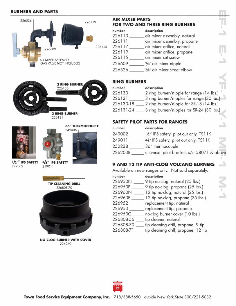
NO-CLOG BURNER WITH COVER226960
TIP CLEANING DRILL226808-70
AIR MIXER PARTS FOR TWO AND THREE RING BURNERS number description
226110 _______ air mixer assembly, natural 226111 _______ air mixer assembly, propane 226117 _______ air mixer orifi ce, natural 226119 _______ air mixer orifi ce, propane 226115 _______ air mixer set screw226609 _______ 3/8 ” air mixer nipple226526 _______ 3/8 ” air mixer street elbow
RING BURNERSnumber description
226130 _______ 2 ring burner/nipple for range (14 lbs.)226131 _______ 3 ring burner/nipples for range (30 lbs.)226130-18 ____ 2 ring burner/nipple for SR-18 (14 lbs.)226131-24 ____ 3 ring burner/nipples for SR-24 (30 lbs.)
SAFETY PILOT PARTS FOR RANGESnumber description
249002 _______ 1/2 ” IPS safety, pilot out only, TS11K249011 _______ 3/8 ” IPS safety, pilot out only, TS11K252238 _______ 36” thermocouple226203B ______ universal pilot bracket, s/n 58071 & above
9 AND 12 TIP ANTI-CLOG VOLCANO BURNERSAvailable on new ranges only. Not sold separately.number description
226950N _____ 9 tip no-clog, natural (25 lbs.)226950P ______ 9 tip no-clog, propane (25 lbs.)226960N _____ 12 tip no-clog, natural (25 lbs.)226960P ______ 12 tip no-clog, propane (25 lbs.)226952 _______ replacement tip, natural226953 _______ replacement tip, propane 226950C ______ no-clog burner cover (10 lbs.)226808-56 ____ tip cleaner, natural 226808-70 ____ tip cleaning drill, propane, 9 tip226808-71 ____ tip cleaning drill, propane, 12 tip
AIR MIXER ASSEMBLY(GAS VALVE NOT INCLUDED)
226119 226526
226609226115
36” THERMOCOUPLE249006
3/8 ” IPS SAFETY249011
1/2 ” IPS SAFETY249002
2 RING BURNER226130
3 RING BURNER226131
15
BURNERS AND PARTS__________________________________________________________________________________________________________________________________________________________________
Town Food Service Equipment Company, Inc. 718/388-5650 outside New York State 800/221-5032
22
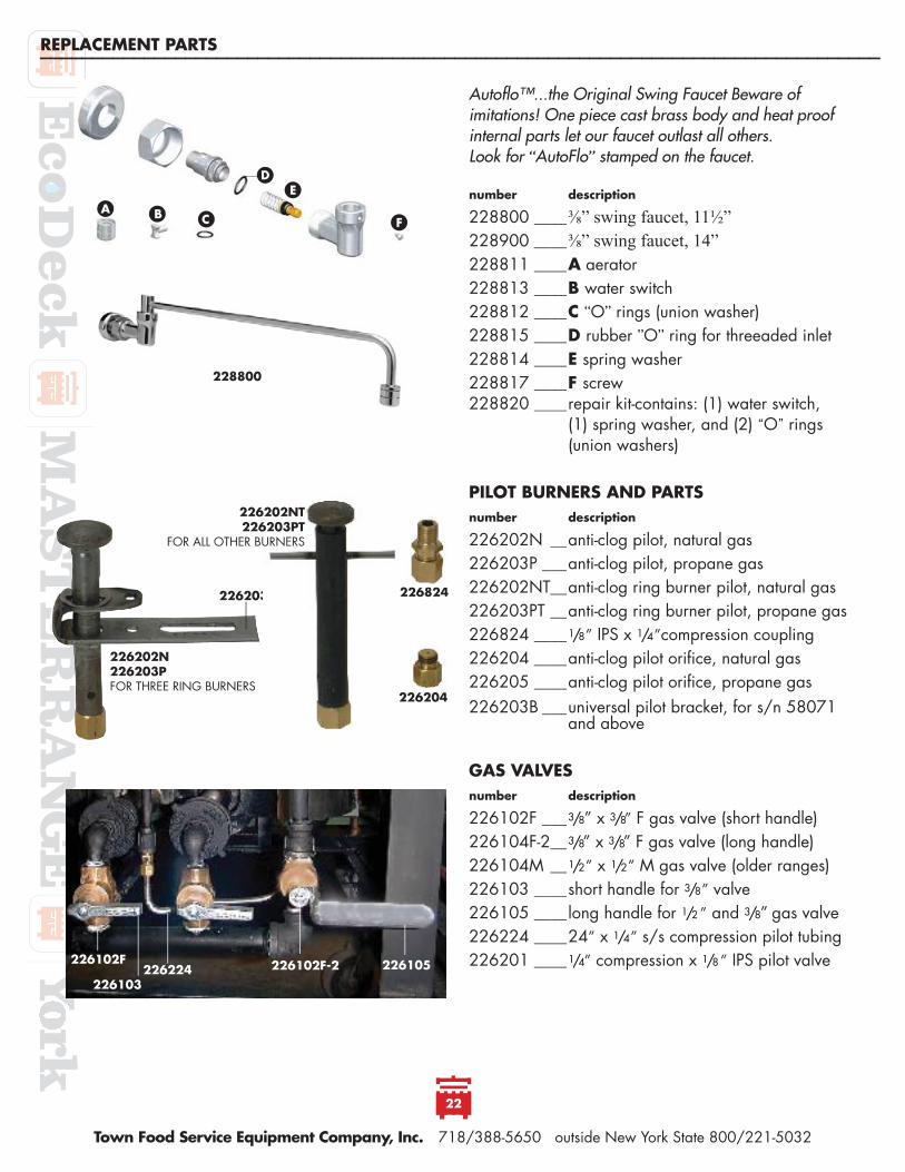
Autofl o™...the Original Swing Faucet Beware of imitations! One piece cast brass body and heat proof internal parts let our faucet outlast all others. Look for “AutoFlo” stamped on the faucet.
number description
228800 ____⅜” swing faucet, 11½”228900 ____⅜” swing faucet, 14”228811 ____A aerator228813 ____B water switch228812 ____C “O” rings (union washer)228815 ____D rubber ”O” ring for threeaded inlet228814 ____E spring washer228817 ____F screw228820 ____repair kit-contains: (1) water switch, (1) spring washer, and (2) “O” rings (union washers)
PILOT BURNERS AND PARTSnumber description
226202N __anti-clog pilot, natural gas226203P ___anti-clog pilot, propane gas226202NT __anti-clog ring burner pilot, natural gas 226203PT __anti-clog ring burner pilot, propane gas226824 ____1/8 ” IPS x 1/4 ”compression coupling226204 ____anti-clog pilot orifi ce, natural gas226205 ____anti-clog pilot orifi ce, propane gas226203B ___universal pilot bracket, for s/n 58071 and above
GAS VALVESnumber description
226102F ___3/8 ” x 3/8” F gas valve (short handle)226104F-2 __3/8” x 3/8” F gas valve (long handle)226104M __1/2 ” x 1/2 ” M gas valve (older ranges)226103 ____short handle for 3/8 ” valve226105 ____long handle for 1/2 ” and 3/8 ” gas valve226224 ____24” x 1/4 ” s/s compression pilot tubing226201 ____1/4 ” compression x 1/8 ” IPS pilot valve
226204
226824
226202N226203P FOR THREE RING BURNERS
226203B
226102F-2 226105226224 226103
226102F
226202NT226203PT
FOR ALL OTHER BURNERS
AC
DE
FB
228800
REPLACEMENT PARTS__________________________________________________________________________________________________________________________________________________________________


LIMITED WARRANTYTown warrants all Smokehouses free from defects of workmanship or material for one (1) year from invoice date with the exception of safety pilot systems which are covered by a 90 day warranty. Safety pilot systems installed without drip legs are not covered by this warranty. Defective parts returned prepaid will be repaired or replaced subject to our inspection and returned freight collect. Mishandling or abuse of equipment or components is not covered by this warranty and repairs or replacement will be made at a nominal charge. Labor costs to return or replace parts in this equipment are the responsibility of the pur-chaser, as are proper installation and adjustments.
RECORD OF OWNERSHIPFOR YOUR RECORDS PLEASE RECORD THE FOLLOWING INFORMATION OF YOUR WOK RANGE
MODEL NUMBER _____________ SERIAL NUMBER _______________DATE OF PURCHASE ________
DEALER _______________________________________DEALER’S PHONE NUMBER _____________