chigo service manual - kondilak.ru · 12). chigo has the right to supervise the service supplier...
TRANSCRIPT

1
CHIGO
Service manual
Room airconditioner
Split Wall-Mounting Type
NOTE:
Before servicing the unit, please first read the service
manual and then contact with your service center if
meet problem

2
Table of the contents
A、 Summary…………………………………………………………. page 3
B 、Wiring diagram…………………………………………………. page 4~5
C、 Installation………………………………………………………. page 6
D、 Exploded view and part list …………………………………. page 16
E、 Components fault and test methods……………………….. page 20
F、 Failure display……………………………………………………page 29
G、 Trouble shooting……………………………………………………………... page 31
H、 Usual failure analysis………………………………………….. page 37
I、 User’s manual ……………………………………………………page 42~50

3
A、Summary
1、 indoor unit
2、 outdoor unit
3 、remote controller
4
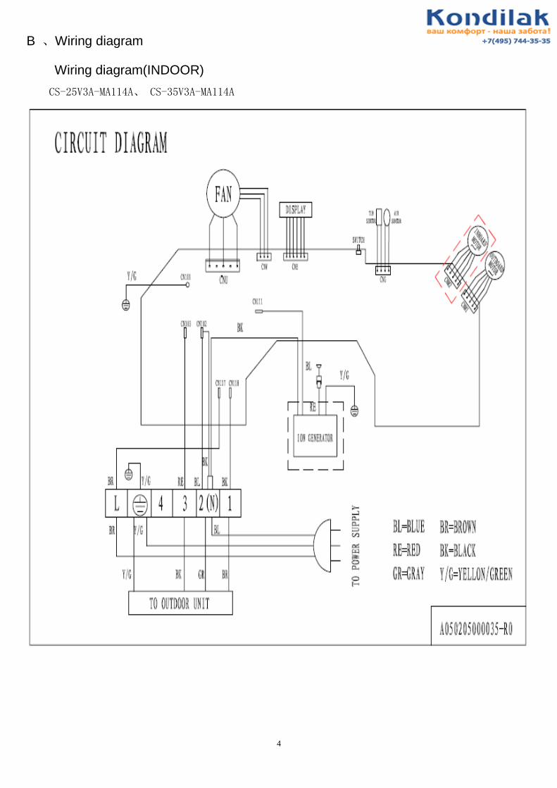
B 、Wiring diagram
Wiring diagram(INDOOR)
CS-25V3A-MA114A、 CS-35V3A-MA114A
5
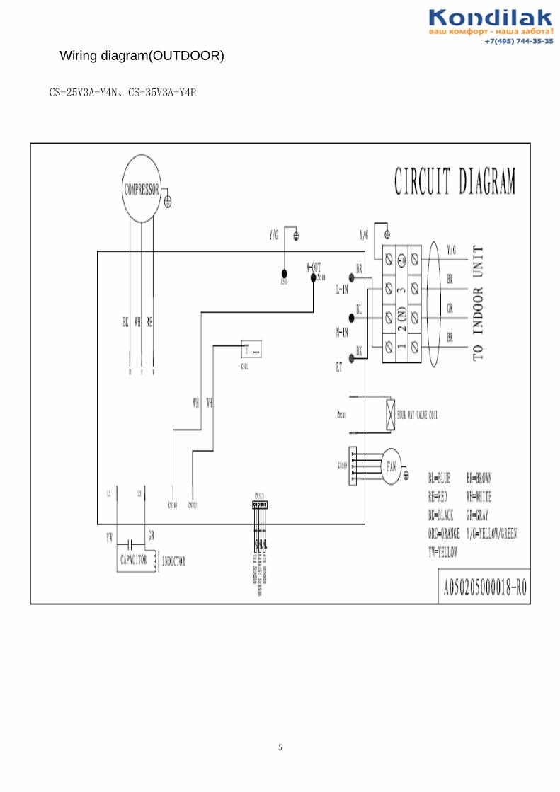
Wiring diagram(OUTDOOR)
CS-25V3A-Y4N、CS-35V3A-Y4P

6
C、 Installation
1、Safety Codes
1). The service supplier shall urge its service people to take effective human safety measures during operation.
2). The service people shall select an installation position that is solid, unlikely shocked and able to support the
weight of machines.
3). To avoid fire, the installation position shall be away from the place where flammable gas exists.
4). When the outdoor unit is installed or relocated on the 2nd
floor of a building or at a height over 2m, the service
people must use the rope with adequate strength to fasten the outdoor unit securely (or take other safety
measures) to prevent the machine from falling down.
5). For working on height, anti-fall measures shall be taken for the tools and materials used outside the building.
6). After completion, the installation people must carry out electrical safety inspection. The electrical wiring must
be in conformance to the national or local safety standards to ensure no leakage.
7). If it is needed to refit the power supply during installation, approval must be obtained from the user and the
operation must be carried out by the people qualified for electrical safety. The result must be in conformance
to the national or local standards on electrical safety.
8). The service people must check each position of the casing during test run. In case of electric leakage,
immediately stop the machine and check it. If it is the problem of installation, solve it and test again. Ensure
the air conditioner works normally. If it is the problem of air conditioner, report it to the vendor.
9). During installation, if the service people find that the user’s power supply has the potential safety problem,
they must notify the user and record the details on the warranty card for confirmation, or take corrective
actions.
10). Before completion of the installation or during removal or installation of the machine, it is prohibited to
switch on the power and start the machine, in order to avoid safety accidents.
11). The service people must follow the national or local safety rules when using the welding tools. The welding
must be performed by the people with safe operation qualification.
12). CHIGO has the right to supervise the service supplier for its work safety. The accidents due to the service
supplier’s fault shall be the service supplier’s responsibility.
13). During installation, the service people shall take care to avoid skid, cutting, scratch, burn, electric shock or
fall. Take care to protect the eyes during welding.
14). After installation, ensure that the people or objects are away from the machine before you connect the power
supply. Do not switch on the power or test the machine until the power supply is correctly connected.
2、Preparation of installation tools
Table: Configuration of Installation Tools
Tool
1. Impact drill, with Ø70mm bit 1
pc
2. Bit, Ø10mm or Ø12mm 1
pc
3. Slotted screwdriver and cross screwdriver, 1
pc for each (mini slotted screwdriver)
Slotted: 100 or 120mm; Cross: 120
or 145mm
4. Torque wrench (2 pcs), spanner (3 pcs) Spanner: 8×10, 10×12, 12×14mm
5. Hammer (1 pc) 0.5Kg
6. Electrical knife (1 pc)
7
7. Wire stripper (1 pc)
8. Sharp nose pliers and cutting pliers (1 pc for
each) Cutting pliers: 150mm
9. Pipe bender (1 set)
10. Pipe expander (1 set) For the expanding the opening of
the added pipe
11. Pipe cutter (1 pc) For cutting the excess copper tube)
12. Reamer (1 pc) For deburring the copper tube
13. File (1 pc) 150 or 200mm
14. Multimeter (1 set) Level 5.0
15. Leakage detector or soap / sponge (1 pc) For detecting if there is leakage at
the connection
16. Thermometer or digital temperature meter (1
pc)
For measuring the temperature of
the intake and outlet air of the air
conditioner
17. Pressure gauge
For measuring the working
pressure of the air conditioner
system
18. Level gauge or plummet (1 pc)
19. Putty scraper (1 pc)
20. Hex wrench (1 set)
21. Electric probe
22. Safety belt
23. Rope (acc. to weight-bearing requirements)
24. Laying cloth, cover cloth, shoe covers,
wiping cloth
25. Ladder and other requisite tools
Other auxiliary materials (depending on the site conditions)
Materials
1. Fixing support for outdoor unit GB/T5059GB/T5213
2. Expansion bolt 10mm (4 pcs)
3. Anchoring bolt (Ø10mm) (with spring
washer) (4 pcs)
4. Concrete nail
5. Heat insulation strap
6. Insulation tape
7. Gypsum powder (1 bag)
8. Copper tube and power cable
9, PVC pipe (optional)
10. Square channel (optional) For fixing the connection pipes
and wires
11. Others

8
3、 Check the machine (whether the appearance is in good condition, and whether the accessories are
complete)
Machine
Inspection
Focus on checking the single cooling, double temperature and cooling capacity
whether conform to the specifications, in terms of the indoor and outdoor units are
compatible, and the style of indoor unit conforms to the requirements.
Look through the observation hole, and check whether the connection pipes,
remote controller, Product Warranty Card and other accessories are complete. If
not, do not open the package but contacting the vendor.
4、 Check the user’s power supply (kilowatt-meter capacity, wire diameter, electric leakage protection switch,
ground wire and voltage)
Check the
power supply
Use the multimeter to measure the power voltage, which shall be within +/-10% of
the rated voltage.
Use special line for the power supply of air conditioners, and ensuring that the
capacity of entire supply line (branch line, power line, kilowatt-meter, air switch,
etc) is higher than the maximum rated current of air conditioner.
The power configuration and cable distribution must meet the local requirements
for electrical safety.
Advise the user to apply special air switch, electric leakage protector and other
necessary protection devices for air conditioners. Their capacity shall meet the
needs of air conditioner. For the line with fuse, it is prohibited to use copper wire
to replace the fuse.
Table: The Requirements of Different Models for Power Supply
Table 1 (220V-240V)
Item
Model Section Area of
Power Cable (mm2)
Circuit Switch
(A)
Split Wall-Mounting Series
25 1.0 10
5 、Selection of Installation Position (Indoor / outdoor lens sequence needs adjustment)

9
Requirement
s for
Installation
Position
The installation shall be operated at the place which is solid, unlikely subject to
shock and able to bear the weight of machine.
The outdoor unit shall be installed at the place which with good ventilation, and
unlikely subject to rain or direct sunshine. Ensuring that the air conditioner can be
easily accessed for maintenance and repair.
Keep the indoor and outdoor units as close as possible. The connection pipe shall be
short as it might be.
To facilitate the air flow, keep adequate space around the indoor and outdoor unit,
and avoid flammable or corrosive gas nearby. The drainage shall not affect the
constructions of dwellers underneath or the user himself.
The machine shall be kept 2m or more away from the electric appliances and heat
source.
Avoid TV set, sound box, computer and other deluxe home appliances below the
indoor unit.
The indoor unit shall be able to blow the cold and hot air evenly to everywhere of
the room.
According to the power supply mode (powered by indoor or outdoor unit) and the
length of power cable, select the position which close to the power supply, in order
to facilitate the connection of power line. Moreover, ensuring that it is not needed to
extend the power cable and selecting a position beyond reach of children.
Determinatio
n of
Installation
Position
Select the final position of indoor and outdoor unit according to the requirements
above (Mark properly if needed).
6、 Execution of Installation
Installation of
Wall-mounted
indoor unit
Unpack the machine and take out the accessories, wall-mounting plate and
remote controller. Mount the bundled batteries into the remote controller and
observe for abnormality. Before installation, make sure to energize the indoor
unit and test it by using the remote controller. Observe the fan and swing
louver for their working conditions. If any abnormality occurs, adjust
immediately and install again.
10
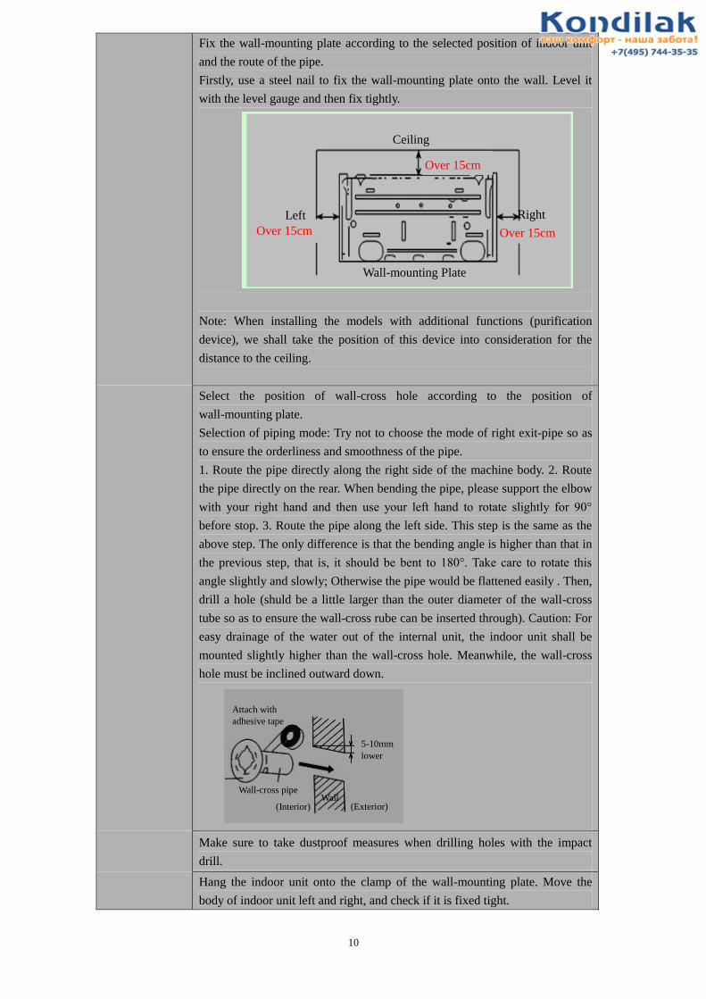
Fix the wall-mounting plate according to the selected position of indoor unit
and the route of the pipe.
Firstly, use a steel nail to fix the wall-mounting plate onto the wall. Level it
with the level gauge and then fix tightly.
Note: When installing the models with additional functions (purification
device), we shall take the position of this device into consideration for the
distance to the ceiling.
Select the position of wall-cross hole according to the position of
wall-mounting plate.
Selection of piping mode: Try not to choose the mode of right exit-pipe so as
to ensure the orderliness and smoothness of the pipe.
1. Route the pipe directly along the right side of the machine body. 2. Route
the pipe directly on the rear. When bending the pipe, please support the elbow
with your right hand and then use your left hand to rotate slightly for 90°
before stop. 3. Route the pipe along the left side. This step is the same as the
above step. The only difference is that the bending angle is higher than that in
the previous step, that is, it should be bent to 180°. Take care to rotate this
angle slightly and slowly; Otherwise the pipe would be flattened easily . Then,
drill a hole (shuld be a little larger than the outer diameter of the wall-cross
tube so as to ensure the wall-cross rube can be inserted through). Caution: For
easy drainage of the water out of the internal unit, the indoor unit shall be
mounted slightly higher than the wall-cross hole. Meanwhile, the wall-cross
hole must be inclined outward down.
Make sure to take dustproof measures when drilling holes with the impact
drill.
Hang the indoor unit onto the clamp of the wall-mounting plate. Move the
body of indoor unit left and right, and check if it is fixed tight.
Ceiling
Left Right
Wall-mounting Plate
Over 15cm Over 15cm
Over 15cm
Attach with
adhesive tape
5-10mm
lower
Wall-cross pipe Wall
(Interior) (Exterior)

11
When multiple indoor units are to be installed in one room (e.g. guest hall,
meeting room, restaurant, etc.), full consideration should be made to the
integral appearance and working performance. They should be installed on the
same level (with the upper as the benchmark) and keep a certain distance, thus
to ensure that the working performance of each indoor unit will not be
affected.
Installation of
Outdoor Unit
1. To install the outdoor unit onto the wall, use the bit of fixed depth to drill
holes according to the selected position, but take care to avoid the wall
clearance. Firstly, mount an expansion bolt 10x100 (mm). Then, use the rope
to move the support outdoors and make a simple fixing. Calibrate the level
with level gauge and mark out the other positioning holes. Then, remove the
support and use the impact drill with fixed depth bit to drill the other fixing
holes of the support. Finally, fix the support onto the exterior wall. 6 pcs
required for model 61 or lower, and 8 pcs required for the model over 61.
Note: The expansion tube of the expansion screw must be fully punched into
the wall.
1. Move the outdoor unit out of the room and put it onto the support with care.
Fix with 4 bolts Ø10mm. (Note: The installation people working on the 2nd
floor or higher must wear safety belt. The outdoor unit must be tied securely
with rope before it can be put outdoors. Take anti-fall measures to avoid
accident. )
2. The outdoor unit is directly onto the ground (e.g. balcony, roof platform,
outdoor ground of the 1st floor, and other platforms that can accommodate the
outdoor unit adequately). According to the size of chassis mounting hole,
select proper expansion screws to fix tightly. The height difference between
indoor and outdoor unit shall not be higher than 5m; otherwise it might cause
difficulty to oil return and affect the service performance.
Required distance of the space around the outdoor unit (unit: mm)
1. With obstacle above Over 300
Ov
er 6
00
2. With front side (outlet port) open
Ov
er 3
00
Over 300
Over 600
3. With obstacles only on front side (outlet port)
Ov
er 2
00
Repair space Keep repair space on the front side of the unit, as shown below.
Over 300
Over 500
Ov
er
50
0
Repair space 4. With obstacle on both front side and back side
Ov
er 3
00
Ov
er 2
000
5. With obstacles on four sides
Though the upper side is open but
there are obstacles on four sides,
the machine cannot be installed
there.
Keep two sides open at least.
Indoor unit
Outdoor
unit

12
Installation Requirements for Multiple Units
1. To install multiple units on the same wall or on the same direction of a
building, all the machines on one floor should be installed on the same level
(based on the level of machine leg), and the transverse spacing shall be kept at
least 60cm or more, as long as the machine performance will not be affected.
2. If there are multiple units on different floors on the same wall or the same
direction of the building, they should be preferably installed on the same
vertical line (based on the left side of the body streamline). To avoid air return
or mutual interference at the outlet, the longitudinal spacing shall be kept at
least 65cm or more.
Requirements for outdoor guardrail (optional): If the user is to install guardrail
for the outdoor unit, the spacing to the machine body must be kept 0.5m or
more.
Insert through
Pipe
Bundle the connection wire to the connection pipe and drainage pipe. (The
connection wire may also be inserted through PVC pipe)
To insert through the pipe, protective measures should be taken to prevent the
expanded bell mouth from damage and prevent the sand from entering the
connection pipe.
Connect to
Machine
Take a connection pipe with expanded mouth, coat frozen oil evenly onto the
connector of the 2-way / 3-way valve and the expanded mouth .
Put the expanded mouth and connector on the same straight line and rotate the
nut to its end with hands, and tighten it with spanner.
Remove the end cover and clip of outdoor connection wire. Then, connect the
wire to position according to color or mark indicated in the wiring diagram.
When the exposed section is fully inserted, use the screw to press it tightly. Do
not cut the round connector at the connection wire end into Y-shape. Fix the
wire with clamp and then fix the end cover of the wire.
Vacuumming
After connecting the pipe between indoor and outdoor unit, it should be
vacuumed with vacuum pump. Operate as follows:
Loosen the nut on low-pressure valve element and filling portal, connect the
vacuum pump to the filling portal by hose with pin, and then start the vacuum
pump. When the indicator gauge points to 15Pa, stop vacuumming and hold
for approx. 30s. Pay attention to the vacuum level. If decreased, be sure to
eliminate the leakage. Repeat the above procedures. When the vacuumming
process is completed, close the vacuum valve and open the high-pressure
valve element for 1/4 turn to fill the refrigerant to the low-pressure section.
Remove the connection hose. Fully open the high-pressure and low-pressure
valves . Tighten the nuts on the valves.

13
Leakage
Detection
Use a sponge soaked with soap water or a leakage detector to check the
connectors and access-valves on indoor and outdoor units. Keep testing for no
less than 3 minutes at each position. When the leakage detection is completed,
do wash away the residual soap water. (Notes: In summer, leakage detection
should be done under stop state. In winter, it should be done under heating
mode). )
Position Most Likely to Leak
Besides four connectors connecting outdoor pipes, nuts at high-pressure /
low-pressure valve core and filling portal are most likely to leak but often
neglected. Therefore, when installing the machine, make sure to fully open the
valve core to dead position and tighten every nut and check for leakage.
The connector with leakage problem should be reinstalled.
Pipe Wrapping
and Wall Hole
Blocking
Sort the pipeline in good order.
Use pipe bender when bend the pipe with 90°. To avoid flattening or cracking
the pipe without pipe bender, do bend it with a radius as large as possible.
Table: Standard of piping torque:
1. Nut torque of connecting pipe (R410a、R407c)
Outer diameter of copper pipe Torque
mm inch Kg.f/m
φ6.00 1/4 1.8
φ9.52 3/8 4.2
φ12.0 1/2 5.5
φ15.88 5/8 6.6
φ19.05 3/4 6.6
2. Nut torque of connecting pipe (R22)
Outer diameter of steel pipe Fastening torque Reinforced
fastening torque
mm inch Kgf/m Kgf/inch Kgf/m Kgf/inch
∮ 6.00 1/4″ 1.6 6.3 2.0 7.9
∮ 9.52 3/8″ 3.0 11.8 3.5 13.8
∮ 12.0 1/2″ 5.0 19.7 5.5 21.6
∮ 15.88 5/8″ 7.5 29.5 8.0 31.5
∮ 19.05 3/4″ 12.0 47.2 14 55.1
Nut for high/low pressure
valve element
Nut for
access door

14
Pipeline
wrapping and
wall-hole
blocking
Wrap the connection pipe and machine-connection wires together, water pipe
shall be placed under the connection pipe and shall not be wounded and
intersected, and it shall be wrapped from outdoor unit to indoor unit in case
rainwater entered and had bad influence on temperature and insulation.
Heat insulation measures shall be adopted separately for the pipeline joint of the
indoor unit.
When the pipeline was wrapped, it shall be fixed on the wall by pipe clamps for
every 1m distance.
Block the wall-hole with plaster or putty with the machine, in case the rainwater
and the wind entered. Meanwhile, make the blockage match the wall as possible.
Inspection
before
machine
testing
Check if the internal wires of the unit are connected. It needs to be noted
particularly that the wires shall be connected correspondingly; the grounding
shall be reliable; and all the naked wires shall be pressed tightly. When the
power was off, the insulating electric-resistance of the null line, the live wire and
the ground wire of the plug shall be more than 2 megohm.
Inspect whether the indoor and outdoor units are installed firmly.
Make sure that all people or objectives are away from the machine, do check it’s
safe before turn the power on.
Power supply
connection
Before installation and safety inspection, electrification is strictly forbidden.
Power connection shall be in accordance to the region or country’s safety
requirments, and make sure that wires were firmly connected.
Inspection for
machine test
When the power is on, turn on the machine by remote controller, and press every
buttom to see if the machine responds. If the machine is a floor standing one,
testing it with control panel is required.
Inspect noise and vibration of the machine, if there are any abnormal
phenomena, they shall be debugged or maintained.
Inspect the drainage of the indoor unit. Pour a cup of water on the indoor unit
evaporator and check the draining situation.
Use remote controller (control panel when floor standing machine) to adjust the
indoor fan to carry out switching of high, medium and low air speed, inspect
whether the air swinging is flexible.
Record the data of working voltage, current, system pressure, temperature,
differences of inlet and outlet air etc. under modes of cooling and heating. In
case of abnormal conditions such as smell, scorched flavor, smoking and so on,
do stop the machine for inspection and solving it immediately. If problems
caused by anything from the user, advices shall be given to improve.
Connection
wire
Connection
pipe
Wall-cross
pipe
Drainage pipe

15
.
7 、Introduction of usage and maintenance knowledge
Test of testing
machine
After start, setting cooling or heating mode according to the temperature.
The installation personnel shall introduce the usage of the remote controller in
detail to the user, including the function of every button, and how to judge the
battery shall be changed and how to change. The power shall be cut and the
battery of remote controller shall be taken out when the machine is not used for a
long time.
Introduce the method of disassembling and cleaning the filter net (replacing the
air filter) to the user, and instruct them to operate until they are skillful. The
outdoor unit shall be ventilated, so as to prevent sundries from blocking the
condenser and influencing the heat dissipation. Users can inspect and clean the
condenser and remove sundries when they can guarantee their safety, or they shall
ask professionals for help.
8、 Ending (clear the site, collect tools, fill the warranty card and say goodbye to the user)
End of work
Hand over the instruction manual and accessories to the user.
Collect the installation tools and do not ignore anything.
Clean installation site, return the displaced articles and electric appliances.

16
D、Exploded view and part list
1、Indoor: CS-25V3A-MA114A、CS-35V3A-MA114A
1 LOUVER
2 THERMAL INSULATION PIPE
3 SWING LOUVER
4 CONNECTING LEVER
5 WATER RESISTANT RING OF WATERPOUT
6 LOUVER SUPPORT POLE
7 GUIDE BEARING
8 OUTLET PART
9 BASE
10 CROSS FLOW FAN
11 BEARING
12 EVAPORATOR
13 EVAPORATOR PLASTIC LEFT PLATE
14 SCREW COVER
15 CLIP
16 AIR FILTER
17 FRONT PANEL
18 Display lamp panel
19 DISPLAY BOX
20 MIDDLE FRAME COVERPLATE

17
21 MIDDLE FRAME
22 TUBE TEMP. SENSOR HOLDER
23 SPRING OF SENSOR
24 COPPER PIPE OF SENSOR
25 EVAPORATOR RIGHT PLATE 1
26 EVAPORATOR RIGHT PLATE 2
27 MOTOR PLATEN
28 TUBE TEMP. SENSOR
29 ROOM TEMP. SENSOR
30 ELECTRIC CONTROL PLATE
31 TRANSFORMER
32 TERMINAL BOARD
33 WIRE CLIP
34 ELECTRIC BOX
35 INDOOR MOTOR
36 POWER CORD
37 CONNECTING CABLE
38 PIPE CLAMP
39 STEP MOTOR
40 WALL-MOUNTING FRAME
41 REMOTE CONTROLLER

18
2、Outdoor:
CS-25V3A-Y4N、CS-35V3A-Y4P

19
1 Front Grill
2 Front Plate
3 Axial flow fan
4 MotorT
5 Motor support
6 Left protect net
7 Pillar
8 Condenser
9 Top panel
10 Rear Grill
11 Four-way valve assembly
12 Intake pipe for the condensor
13 Suction pipe
14 Capillary Assy
15 Suction pipe
16 Discharge pipe
17 Electrical boxes
18 Right panel
19 Large handle
20 Valve installation plate
21 High-pressure valve
22 Low-pressure valve
23 Base
24 Compressor
25 Partition board
20
E、 Components fault and test methods
1、Ordinary compressor
1): Ordinary test (power off)
Testing method:
Check the compressor by eyeballing first. If there has burnt vestiges on the surface of compressor or the
compressor gives out the bad smell, the reason mainly is that the winding is burnt. If the compressor terminal
is burnt, mostly it is caused by the heavy current or the bad contact.
2):Resistance test
①、short circuit: Measure resistance of each winding by universal meter, if the resistance value is lower than
the standard, the winding may short circuit.
②、open circuit: Measure resistance of each winding by universal meter, if the resistance value is infinite, the
compressor winding may open circuit.
3): Electric leakage & insulation test
Measure resistance between the points of winding and other part of compressor by universal meter, if the
resistance value is infinite, means no electric leakage and the insulation is perfect. If the resistance value is
tiny or zero, electric leakage may exist in compressor or insulation material may be aged or broken.
2、AC motor of indoor and outdoor unit
1)、General inspection
Testing method:
In the case of non-power,twist motor rotor by hand,meanwhile shaking motor. checking is there any
rust,whether blocked.
Fault judgement:
If the motor rotor can’t twist, that means the motor blocked. when shaking motor,there should be no
abnormal noise, if the noise of inside the motor is small,it means motor shaft loose.if the noise of inside the
motor is big,it means there is sundries inside of motor or electrical components loose.
2)、DC resistance
(1)turn-to-turn short circuit:measure entire winding resistance by multimet,if the difference between
measured value with standard value is larger,it means turn-to-turn short circuit.
(2)opencoil: measure entire winding resistance by multimet,if the resistance is ∞,means opencoil.
3)、Electric leakage & insulation test
Measure resistance between the points of winding with other part of motor by universal meter, if the
resistance value is infinite, means no electric leakage and the insulation is perfect. If the resistance value is
tiny or zero, electric leakage may exist in motor or insulation material may be aged or broken.
3、general Electric control panel(PCB)
1)、test method for common electronic component,

21
(1) SCR: measure resistance between control electrode and positive electrode by multimeter, model Z47 is
20Ω to 400Ω, BT131 is 1.4K ~ 1.7K, if the resistance is too large or too small, means not normal. And if
the resistance between other electrode is infinite,means SCR damaged.
(2) Check the voltage between input terminal and output terminal.if input voltage is ok and did not have the
output voltage,need to replace the relay.
(3) Optocoupler: the red pen connect the first leg of optocoupler, black pen connect the second leg.if the
forward Resistance is about 1K,and the resistance between other feet is infinite, means optocoupler
damaged.
(4) transformer: primary coil resistance is 400Ω ~ 1000Ω, Secondary coil resistance is 15Ω ~
40Ω,transformer damaged if deviation is big.
(5) Temperature protective tube, varistor: resistance of protective tube should be 0Ω, that is, resistance of
varistor should be infinite.
(6) Main Chip: check the working voltage (5V) and voltage of reset feet and crystal oscillator, and then check
peripheral components Step by step.
(7) 2003(IC): 2003 is an inverter, in the working condition, input and output potentials are always contrary,.
(8) Diodes: choose “diode” from multimeter, then the red pen connect positive pole, black pen connect
negative pole, the resistance should be a few hundred ohm.the reverse resistance is infinity, otherwise
diode is bad.
(9):Transistor:
①: NPN transistor: choose “diode” from multimeter,red pen connect base、black pen connect other two
feet. and the resistance should be a few hundred ohm, otherwise the transistor damaged.
②: PNP transistor: choose “diode” from multimeter,black pen connect base、red pen connect other two
feet. and the resistance should be a few hundred ohm, otherwise the transistor damaged.
(10) Infrared Receiver Module: choose “diode” from multimeter,black pen connect power pin、red pen
connect other two feet. and the resistance should be a few hundred ohm, otherwise the transistor
damaged.
(11) Crystals: check voltage of crystals.the normal voltage is 2.1 V - 2.5 V,otherwise the crystals damaged.
2)、Charged detection:
(1) Connect PCB with Test-bed.check mode、wind speed、temperature and so on according to the remote
control and control panel. PCB should receive signal accurately and correctly, and indicator light should
feedback correctly or check whether has the correct output signal by a multimeter(such as: compressor、
fan、four-way valve、electrical heating、step motor、synchronous machine、negative ion、High voltage
generator、Dc decelerating motors.)
(2) Each function control key should be flexible,
(3) For liquid crystal display or fluorescence display,character should be clear and correct; There should not
have the ghosting,brightness blance. Light board display normally, have no obvious Unnormal flicker.
(4) step motor should be able to rotate;;
(5) For the PCB with self-test function,press the self-test button, and then enter the self-test program.the
output should be consistent with the design requirements,no procedures chaos or system halted.
3)、Common fault detection
(1) unit doesn’t work
a), check whether input and output voltage of the transformer is normal (input AC220V, Output AC10V
~ 14V), if no problem,then check the next step;
b), check whether “three-terminal voltage regulator 7805” is normal, if no problem,then check the next
step;
c), check whether the voltage of crystal oscillator is normal (2.1V-2.5V), if not, replace crystal;

22
d), if all above are normal,then replace the main chip.
(2) display bad or indicator light does not shine
Showing bad or light does not shine
a), check whether the voltage of display board is normal (5V);
b), check whether the resistance of display lamp is normal(light-emitting diode forward resistance is a
few hundred ohms,)
c), check whether chip is cold solder joint, short circuit, or replace the chip.
(3) Buzzer does not ring or abnormal:
a), check whether the voltage of Buzzer is normal(about 12V),if normal,then check the next step ;
b), check whether the Buzzer is noiselessly..
(4) Not receive or receiving is insensitive
a), check whether the wire of receiver is normal, or replace the connecting wires;
b), check whether the voltage of receiver is normal(5V), or check the power supply circuit;
c), check whether the receiver is normal.if normal,check whether the main chip is normal, otherwise,
replace it.
(5) sensor failure
a), check whether the voltage of room temperature sensor and pipe temperature sensor is normal (make
sure at the same temperature conditions,the voltage difference between these two sensors can not be
greater than 0.1V, otherwise need to replace).
b), take down the sensor and measure the resistance, its resistance should be within standard deviation.
(6) Indoor fan failure
a), check whether capacitance of fan is the same with nominal value.or replace the capacitor or check
the next step.
b), for the tap fan,check voltage of high, medium and low wind relay.the normal voltage is DC12V.
c), for the tap fan,check whether the relay is normal.or may replace relay;
d), check whether the AC power supply circuit is normal, or replace related devices.
e), for the PG fan,check whether SCR (C1815) is cold solder joint, loose, this circuit is normal or not.
f), for the PG fan,check whether voltage of SCR (C1815) is normal (Point C is about 0.3V,Point b is
about 0.7V ,point e is 0V), or replace the C1815.
(7) step motor does not run or not good at running.
a), check whether solder joint of step motor is cold solder joint, loose and short-circuit for rosin, the
main chip, the output voltage of control pin is about 2V,or check whether the main chip is normal or
checking the next step;
b), check 4-pin voltage which connect the step motor with 2003 is normal(10 ~ 12V), or check the
2003 or the connecting wire.
C), check whether the connecting wire of step motor and the motor is normal.
(8) The relay does not work
a), check whether the voltage of the relay coil is normal (usually about 12V), otherwise check whether
the relays is normal or checking the next step;
b), check whether the relay is good, otherwise replace of relay;
c), check whether the output pin of the main chip is high (5V), or check whether the main chip is
normal or checking the next step.
d), check whether the power supply circuit, transformer input and output voltage is normal,or checking
the next step;
e), checking whether the piezoresistor and temperature insurance are normal.( the resistance of
piezoresistor is infinite.the resistance of temperature Insurance is 0) otherwise, check related

23
componentsthe or checking the next checks;
(9) key is invalid
a), check whether the output pin of the button is normal, or replace;
b), check whether the voltage of display board is 5V, otherwise, check the power supply circuit or
connecting wire;
c), If all above are normal, check whether the main chip is normal, or replace the main chip.
4)、Electric control panel detection
① red power indicat( LED1) is not bright:
a), check whether the LED1 is damaged, if damaged,please replace the diode;
b), check whether the input and output voltage of the 7812 and 7805 is normal (7812 input 14V, output
is about 12V,7805 input 12V, the output 5V), if damaged,replace the related device or check downward;
c), check whether the bridge rectifier diodes D1-D4 is normal,if the damaged,please replace related
diode;
d), check whether the power supply transformer of input and output is normal (input is about AC220V,
the output is about AC14V), if it is damaged,replace the transformer.
② Green light LED2 does not shine or the phase sequence protection
a), check whether the light-emitting diode LED2 damaged, if not normal,then the replace the
light-emitting diode;
b), check whether the Q5 (9014) collector voltage is normal, if not normal,then the replace 9014;
c), check whether the relay RY3 is normal, if not normal,then the replace the relay;
d), check whether the resistance of the R7-R10 is normal, if not normal,then the replace the related
resistance;
e), check whether the phase sequence of the three-phase power supply is normal, if not ,then the
replace phase sequence.
③ No-voltage for over-current detection circuit
a), check whether the rectifier diodes D5-D8 is normal, if not normal,replace related diode;
b), check whether the current transformator L1 is normal (resistance of ③ ④ foot should be around a
few hundred ohms),if abnormal,replace it.
④ Over-current protection too long or too short.
Check whether capacity of capacitance E3, E6 is normal (the normal over-current protection is about
20s ~35s), replace if it is not normal,
⑤ appear over-current protection
a), check whether the integrated block LM311 (7) feet IC3 is normal,if not normal,check IC3.if
damage, replace it,
b), check whether triode 9012 is normal.if abnormal,replace it,
c), check the voltage of over-current relay coil is normal (about12V), if it normal,check whether the
relay damage.
⑥ no defrost signal temperature signal (defrosting relay can’t break)
a),check whether the temperature sensor is normal(measure sensor resistance), if the resistance is too
large or too small or even infinite, or 0Ω, then replace sensor;
b), check whether the voltage of the defrost relay coil is normal(about 12V), if it’s normal, check
whether the relay damage.

24
4、capacitor
①、appearance inspection
Testing method:
Visual inspection whether the appearance of capacitor expansion, burst.if it was,that means the
capacitor fail.
②、check by open circuit
Testing method:
Check the capacitance by multimeter,If the pointer could swing to the right at once,then the pointer
slowly reset to 0.that means the capacitance is no problem.if the pointer does not move or do not
reset,means capacitance is open circuit, electrolyte dry, or short-circuit
③、capacitance breakdown,leakage of electricity
Testing method:
Check the capacitance by multimeter,If the pointer couldthen the pointer can’t move.that means the
capacitance is breakdown or leakage of electricity
④、Loss tangent inspection (as understanding project)
Judge standard:
run about 10 minutes,check surface temperature of capacitance.If the surface temperature exceeds
the ambient temperature about 15 ℃,that means loss tangent has exceeded the limitvalue 0.0018.
⑤、Check capacitance
check by pointer type multimeter: if the pointer oscillation amplitude is bigger than the standard
capacitance,that means capacitance has been attenuated.
Digital Multimeter:check by Cx interface,the capacity should not exceed the nominal capacity of ±
5%.
⑥、Insulation inspection
Testing method:
normally,the resistance of capacitance is ∞, if the number of resistance is thousands of ohms or
greater, that means capacitance is no problem. if the resistance is smaller or 0,that means capacitance
has been damaged, should be immediately replaced.
5、transformer
1)、Visual inspection
check whether the appearance of transformer burnt phenomenon, check whether has the burnt
transformer smell. If the appearance of burnt yellow phenomena or had burnt smell, transformer
winding is bad.
2)、Check on running
Testing method:
make transformer running under load (which can run with PCB),should be running smoothly, there
shouldn’t be unusual noise. if there is unusual noise,it is multi-electromagnetic noise.
3)、Electrical Characteristics

25
(1) No-load characteristics
as for the power supply 220V/50Hz, 220V/60Hz, 240V/50 Hz, power 5 ~ 8W .
transformer primary load current ≤ 20mA; power supply 115/60Hz; power 5 ~ 8W of the transformer
primary No-load current ≤ 35 mA; no-load output voltage does not exceed rated voltage +10%.
(2) Load Characteristics
transformer at rated load conditions; the error of the secondary coil voltage should not be greater than
the requirements in Table 1;
4)、Output power
(1), measured current and voltage with the multimeter,and then according to P = UI, the output power
should not exceed transformer nominal requirements of ± 8%, If you exceed this requirement, you can
determine the transformer's power attenuation.
(2) According to P=U2/R,the output power shall not exceed the transformer nominal requirements of ±
8%, If you exceed this requirement, you can determine the transformer power attenuation.
5)、DCR
(1) turn-to-turn short circuit:
check by multimeter, select the appropriate range, measure the resistance of transformer winding,if the
deviation between real resistance with the standard resistance is great,that means the inter-turn short
circuit and outlet the open circuit.
(2) Coil Open circuit:
check by multimeter, select the appropriate range, measure the resistance.if the resistance is ∞, that
means transformer coil open circuit or open circuit.
6)、Insulation inspection
(1) insulating property between the shell and the iron core
Testing method:
check by multimeter, select the appropriate range, measure the resistance.if the resistance is ∞or tens
of thousands of ohms,means insulating property is good.if the measured resistance of the smaller or
0,means core screen has been destroyed.
(2) insulation between the windings
Testing method:
check by multimeter, select the appropriate range. one pen contacts with the transformer primary,the
other contacts with secondary output transformer.if the resistance is ∞ or tens of thousands of
ohms,means insulating property is good.if the measured resistance of the smaller or 0,means core
screen has been destroyed.
6、remote control
1), visual inspection
(1) injection parts should be no deformation, no mask loose, tilt phenomenon.
(2) The battery should be in a good elasticity with no rust.
(3) liquid crystal display without bubbles,display clear, correct, not more paragraphs, , ghosting and black.
2)、Function test
The battery into remote control, LCD display should clearly show the content (non-LCD display does not

26
check this). The receiver should be able to receive the instructions accurately.
3)、Common fault
(1) key failure
Testing method
make sure the unit running, installed battery to remote control, press various function keys.
Fault judgement
a), if multiple buttons are not work,the main reason is for the bad chip.
b), if sometimes normal, and sometimes fail, then the main reason is the underlying part has a impurity.
(2) No emission signal
Testing method:
make sure the unit running, installed battery to remote control, press various function keys.
Fault judgement
If the remote control without signal, but the display and other functions are normal,then most of the
reason is that a bad emission tube. If the display is not normal, normally chip damage.
(3) Testing method:
make sure the unit running, installed battery to remote control, press various function keys.
Fault judgement
If the remote control is neither transmit nor display,means chip resistors, chip capacitance, crystal 1
(iron crystal) and other damage, If you press reset button, remote control full screen then back to not
show the status, then the most for crystal 2 (ceramic oscillator) is damaged.
(4) Show insufficiency
Testing method:
make sure the unit running, installed battery to remote control, press various function keys.
Fault judgement
If the remote control showing the insufficiency phenomena that are mostly liquid crystal rupture,
leakage and other causes.
4)、electrical properties
(1) tandem the ammeter with remote control, in the DC 3.0V voltage ,if unit can not launch a signal,in
the unit with liquid crystal display,the quiescent current ≤ 70uA, in the absence of liquid crystal
display , the quiescent current ≤ 20uA.
(2) under the voltage of 2.6V,remote control should be able to work properly. In not more than 80% of
the rated voltage (2.4V),the LCD of remote control should be able to clearly show.
7、four-way valve
11))、、GGeenneerraall iinnssppeeccttiioonn
Visual inspection: pull coil of each power cord, wires should be no break phenomenon;
2)、DCR
(1) turn-to-turn short circuit:
check by multimeter, select the appropriate range, measure the resistance.if the resistance
smaller than the standard resistance.it means four-way valve turn-to-turn short circuit.
(2) coil Open circuit:
check by multimeter, select the appropriate range, measure the resistance.if the resistance is ∞, .it
means four-way valve open circuit.

27
3)、insulating property
Testing method:
check by multimeter, select the appropriate range. one pen contacts with input terminal,the other contacts
with body.if the resistance is ∞ or tens of thousands of ohms,means insulating property is good.if the
measured resistance of the smaller or 0,means core screen has been destroyed.
4), run on power
Testing method:
connect the four-way valve and the electrical components,connected to rated power; change the mode
between cooling and heating mode,check whether the four-way valve could correctly change.
Fault judgement:
if the four-way valve could not change correctly, means four-way valve bad or wire partial short-circuit
fault.
8、step motor
11))、、GGeenneerraall iinnssppeeccttiioonn
Testing method:
Visual inspection: check whether the appearance of step motor is burnt, rust. If have,that means the
winding of motor is broken.In the case of non-power,hand knob step motor's output shaft,if there exist
strange noise,that may be caused by driving wheel not matching or loose for connecting piece.
2)、Check torque
Self-positioning Torque:
under the action of this torque, step motor should not lose, not jitter, non-skid.
3)、Resistance test
① short circuit: Measure resistance of each winding by universal meter, if the resistance value is
lower than the standard, the winding may short circuit.
② open circuit: Measure resistance of each winding by universal meter, if the resistance value is
infinite, the compressor winding may open circuit.
4)、Check on running
Testing method:
make sure step motor running with load, there shouldn’t be unusual noise. if there is unusual noise,it
is caused by rust or wear. If the step motor does not work, most is due to open coil, short circuit, or rust.
5)、insulating property
Testing method:
check by multimeter, select the appropriate range. one pen contacts with input terminal,the other
contacts with body of step motor.if the resistance is ∞ or tens of thousands of ohms,means insulating
property is good.if the measured resistance of the smaller or 0,means core screen has been destroyed.
6)、electrical performance checking
Testing method:
use needle nose pliers or similar tool clamp output shaft of the motor,rotate it clockwise.at the same
time, choose AC 20V voltage,then connect two pens with step motor input end.after rotating the output

28
shaft there should be clear voltage shows on multimeter.
9、synchronous motor
11))、、GGeenneerraall iinnssppeeccttiioonn
Testing method:
Visual inspection: check whether the appearance of synchronous machine is burnt, rust. If have,that
means the winding of motor is broken.In the case of non-power,hand knob output shaft,if there exist strange
noise,that may be caused by driving wheel not matching or loose for connecting piece.
2):Resistance test
① short circuit: Measure resistance of each winding by universal meter, if the resistance value is
lower than the standard, the winding may short circuit.
② open circuit: Measure resistance of each winding by universal meter, if the resistance value is
infinite, the compressor winding may open circuit.
3)、Testing method:
check by multimeter, select the appropriate range. one pen contacts with input terminal,the other contacts
with body of step motor.if the resistance is ∞ or tens of thousands of ohms,means insulating property is
good.if the measured resistance of the smaller or 0,means core screen has been destroyed.
4)、Check on running
Testing method:
make sure synchronous machine running with load, there shouldn’t be unusual noise. if there is unusual
noise,it is caused by rust or wear. If it does not work, most is due to open coil, short circuit, or rust.
5)、Torque checking
Testing method:
make sure the motor running by rated power, use needle nose pliers or similar tool clamp output shaft of
the motor till making the motor stop.
Fault judgement:
At rated voltage, frequency, braking torque of synchronous machine should be ≥ 0.345Nm, if the output
shaft of the torque is less than 0.345Nm, can be found the torque is not enough, can not bring the
throttle to run.
6)、electrical performance checking
Testing method:
use needle nose pliers or similar tool clamp output shaft of the motor,rotate it clockwise.at the same
time, choose AC 20V voltage,then connect two pens with step motor input end.after rotating the output
shaft there should be clear voltage shows on multimeter.

29
F、 Failure display
Check
parts
Serial
number
Malfunction content Indoor unit display status
Code LED(Indoor unit without the
nixietube)
Running lamp
flashing
frequency n
Timing lamp
flashing
frequency n
Indoor
parts
1 The communication
faults in the indoor and
outdoor units
F1
1 lighten
2 Indoor ambient temp.
sensor fault
F2 2 lighten
3
Indoor coil temperature
sensor fault (Include:
Inlet, middle of pipe,
outlet.)
F3
3 lighten
4 Indoor fan fault F4 4 lighten
Outdoor
parts
1 Outdoor module fault F5 5 lighten
2 Outdoor ambient temp.
sensor fault
F6 6 lighten
3 Outdoor coil temp.
sensor fault
F7 7 lighten
5 Compressor discharge
temp. sensor fault
F9 9 lighten
7 Compressor drive
abnormal fault
FC 11 lighten
10
Other fault
FF 14
lighten
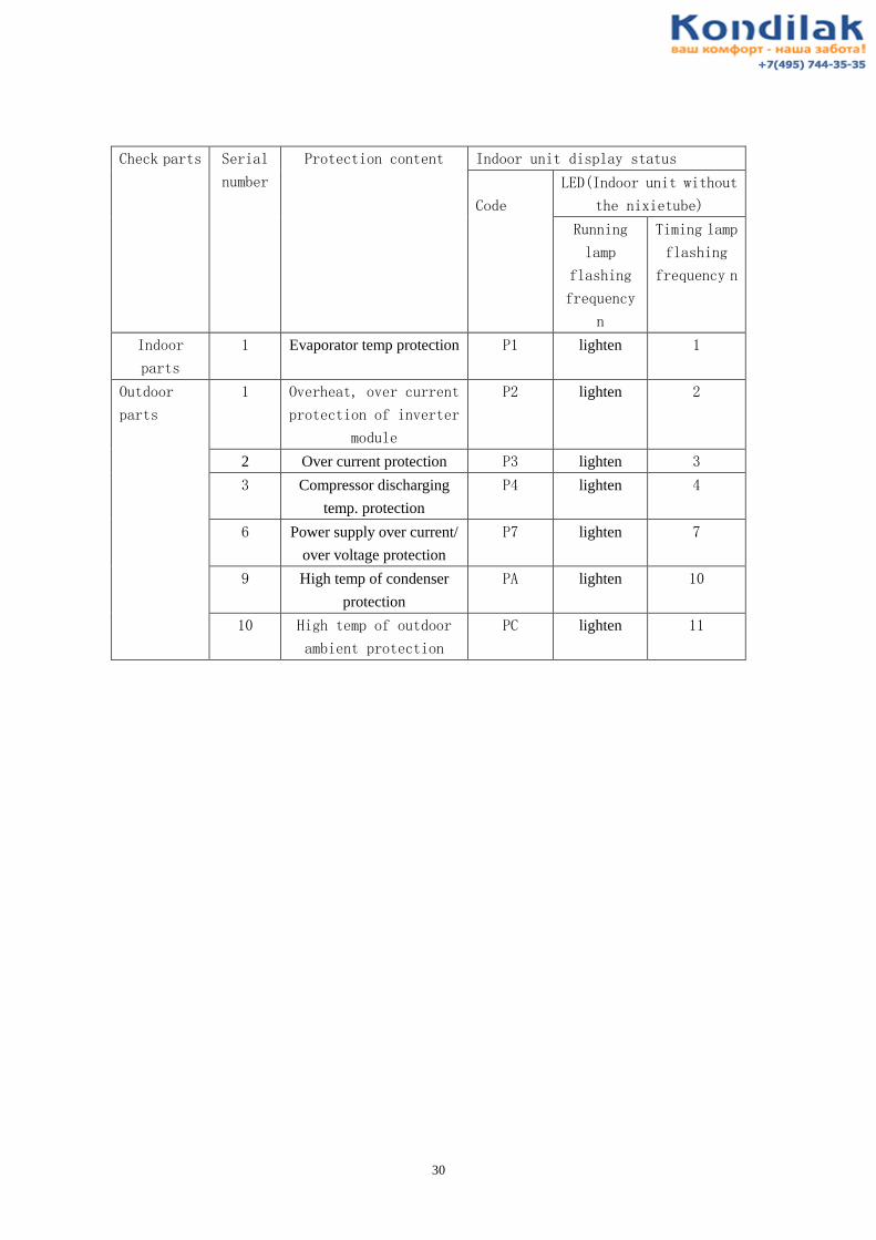
30
Check parts Serial
number
Protection content Indoor unit display status
Code
LED(Indoor unit without
the nixietube)
Running
lamp
flashing
frequency
n
Timing lamp
flashing
frequency n
Indoor
parts
1 Evaporator temp protection P1 lighten 1
Outdoor
parts
1 Overheat, over current
protection of inverter
module
P2 lighten 2
2 Over current protection P3 lighten 3
3 Compressor discharging
temp. protection
P4 lighten 4
6 Power supply over current/
over voltage protection
P7 lighten 7
9 High temp of condenser
protection
PA lighten 10
10 High temp of outdoor
ambient protection
PC lighten 11

31
G、 TROUBLE SHOOTING
Is CN (Tr sensor connector)
connected properly?
Is Tr sensor resistance value
(5KO at 25? ) normal?
Indoor P. C. board is defective. Replace P. C. board.
Connect CN properly.
Replace TA sensor.
Is CN (TP1 sensor connector)
connected properly?
Is TP1 sensor resistance value
(5KO at 25? ) normal?
Indoor P. C. board is defective. Replace P. C. board.
Connect CN properly.
Replace TC sensor.
YES
YES
YES
YES
NO
NO
NO
NO
Indoor Tr sensor
error
Indoor TP1 sensor
error

32
Turn off power
supply once, and
turn it on again.
Does
compressor
continue to
operate?
Start to operate indoor
unit in cooling
operation at airflow
level “ LOW” ,wait
three minutes..
Does indoor
fan operate?
Fan motor
operates
normally.
Is it possible to detect AC
220V between
pin(high/middle/low) and
pin(common) of motor
connector .
Replace indoor
fan motor.
Replace main
P.C. board.
Replace
bearing.
YES
YES
YES
NO
NO
NO
Turn off indoor unit and rotate
cross-flow fan by hand when the
unit is on standby.Is it possible to
rotate cross-flow fan by hand
properly?
Only indoor fan motor does not operate.
Is capacitor of indoor fan ok?
YES
NO
YES
Replace
capacitor
NO
<Primary check>
(1) Is it possible to detect the power supply voltage (200-240V) between L and N on the terminal
block?
(2) Does the indoor fan motor operate in cooling operation?

33
Compressor does not operate.
Turn on power supply.
Does compressor delay
three minutes by
temperature changes or
others?
Does OPERATION
indication indicate?
Is it possible to detect AC
220-240V on terminal
block or contactor of
compressor?
Are all of compressor
cords normal?
Is compressor motor
winding normal?(Check
winding resistor.)
Is capacitor for
compressor normal?
Is overload relay normal?
Does compressor start?
Does compressor stop
after a while?
Is gas quantity normal?
(Check gas pressure.)
Microcontroller is defective or
miniature relay is defective..
Is resistance value of room
sensor (Tr) and heat exchanger
sensor (TP1) normal?
Room sensor or heat
exchanger sensor is
defective.
Replace room sensor
or heat exchanger
sensor.
Compressor is defective.
Capacitor is defective.
Overload relay is defective.
Compressor is defective.
Gas shortage (Gas leak)
Compressor is defective.
Replace P.C. board.
Rewire or replace
defective cords.
Replace compressor.
Replace capacitor.
Replace overload
relay.
Supply gas.
Replace compressor.
YES
YES
YES
YES
YES
YES
YES
YES
YES
YES
YES
YES
NO
NO NO
NO
NO
NO
NO
NO
NO
NO
Check power supply.
Replace compressor.
Wait three minutes
<Primary check>
(1) Is the room temperature higher than the preset temperature in cooling operation?
(2) Is the crossover cable connected properly?

34
Replace
P.C. board.
Is receiver on
indoor unit exposed
to direct sunlight?
Batteries are
exhausted.
Press START/STOP
button.
Is there any thyristor
fluorescent light
nearby?
Does indoor unit
operate when
moving remote
control near receiver
or indoor unit?
P.C. board is
defective.
Is transmission
mark indicated?
Press RST button
on remote control
with tip of pencil.
Press START/STOP
button.
Does radio sound is
affected by remote
control when a
signal is transmitted
at distance of 5 cm
from radio?
Does indoor unit
start to operate by
automatic restart
function?
Is transmission
mark indicated?
Does indoor unit
beep and operate?
Remote control is
defective.
Keep indoor unit
away from
thyristor
fluorescent light.
Avoid direct
sunlight.
Replace
batteries.
Normal
operation
Replace remote
control.
The unit does not beep at all.
OPERATION indication on
indoor unit is not indicated.
NONO
NONO
NO
NO
NO
YES
YES
YES
YES
YES
YES
YES
YES
NO
YES
YES
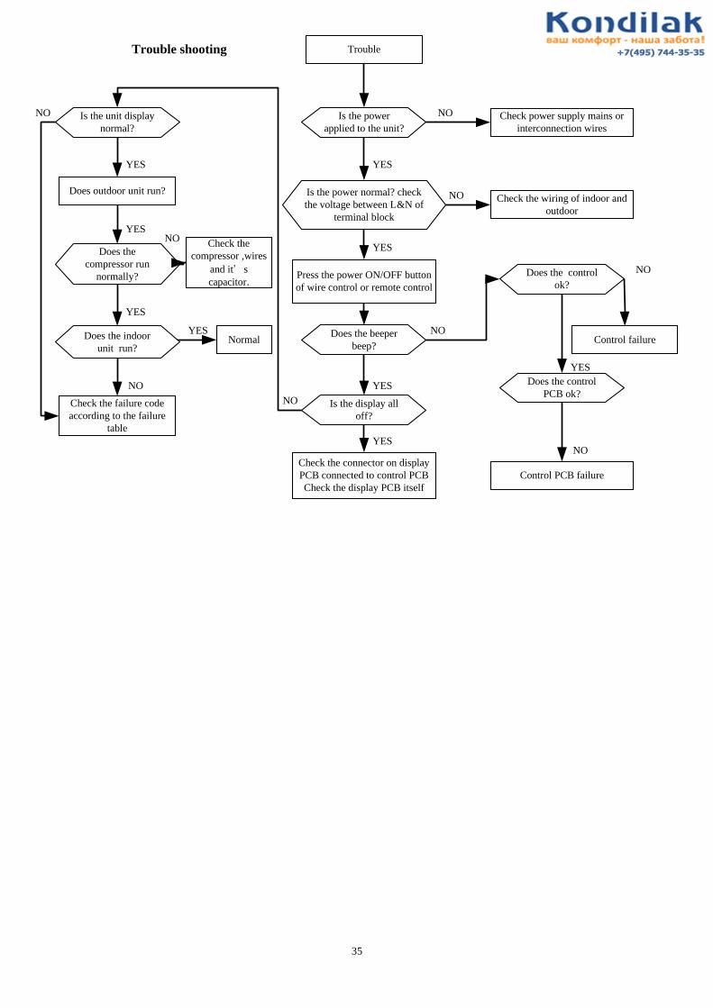
35
Trouble
Is the power
applied to the unit?
Check power supply mains or
interconnection wires
Is the power normal? check
the voltage between L&N of
terminal block
Check the wiring of indoor and
outdoor
Press the power ON/OFF button
of wire control or remote control
YES
YES
NO
NO
Does the beeper
beep?
Is the display all
off?
Check the connector on display
PCB connected to control PCB
Check the display PCB itself
Is the unit display
normal?
Does outdoor unit run?
Does the
compressor run
normally?
Check the failure code
according to the failure
table
Normal
Check the
compressor ,wires
and it’ s
capacitor.
YES
YES
YES
YES
YES
YES
NO
NO
NO
Does the control
ok?
Does the control
PCB ok?
Control failure
Control PCB failure
NO
NO
YES
NO
Trouble shooting
NO
Does the indoor
unit run?
36
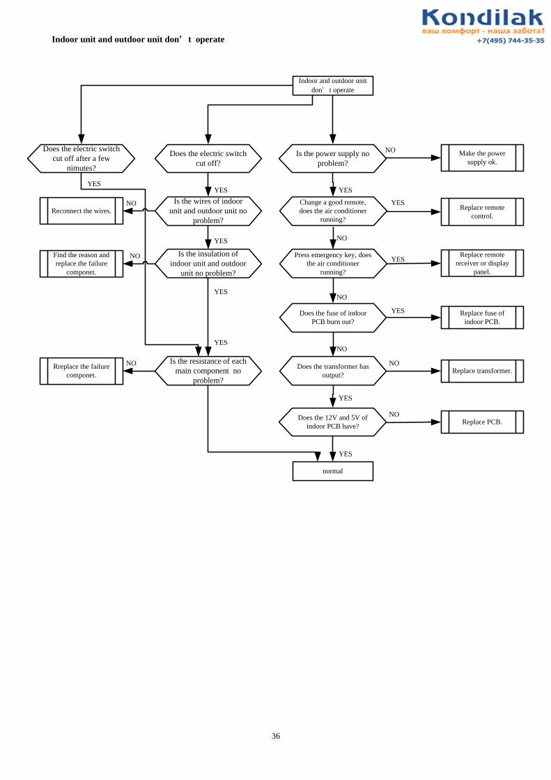
Indoor unit and outdoor unit don’ t operate
Indoor and outdoor unit
don’ t operate
Press emergency key, does
the air conditioner
running?
Replace fuse of
indoor PCB.
YES
YES
YES
NO
NO
NO
NO
Make the power
supply ok.
Replace remote
control.
YES
NO
Replace remote
receiver or display
panel.
NO
YES
YES
Replace transformer.Does the transformer has
output?
Does the fuse of indoor
PCB burn out?
Change a good remote,
does the air conditioner
running?
Is the power supply no
problem?
Does the 12V and 5V of
indoor PCB have?Replace PCB.
normal
Does the electric switch
cut off?
Does the electric switch
cut off after a few
nimutes?
Is the wires of indoor
unit and outdoor unit no
problem?
YES
Reconnect the wires.NO
Is the insulation of
indoor unit and outdoor
unit no problem?
YES
Find the reason and
replace the failure
componet.
NO
Is the resistance of each
main component no
problem?
Rreplace the failure
componet.
NO
YES
YES
YES

37
H、Usual failure analysis
No.
Fault
The possible reason
Solution
01 Not cooling well.
The room is too large ;the
window or door is not closed.
Close the window and door
Too many persons or heat
source in room.
Reduce the heat source.
The installed position of outdoor
unit isn’t good. Have insolation
or not good in ventilation.
Reinstall the unit.
The installed position of indoor
unit isn’t good. Bad in air
circulation.
Reinstall the unit.
The air filter is dirty or blocked. Clean this air filter.
The system blocked. Check capillary tube, strainer
etc. repair or replace them.
The refrigerant leakage. refill up refrigerant after
checking the leak source.
The set temperature is too
high .
reduce the set temperature.
The condenser blocked by dust
or others.
clean the dust and dirt.
Too much quantity of
refrigerant.
take the redundant refrigerant
out.
Blockage in airinlet or air outlet. Clear the obstacles.
Air mixed in refrigerant. refill the refrigerant.
High outdoor temperature.
The indoor or outdoor fan motor
is running slow
Change this indoor or outdoor
fan motor
The compressor suction or
venting capability is very poor
Change this compressor
Four-way valve slight mixes up replace it
other
02
Can not cool.
The fan doesn’t run (motor or
capacitor of fan failed, Poor
contact for the line of capacitor,
line fault. The motor relay and
drive circuit is fault)
Check. Repair and replace.
The compressor doesn’t
work(the voltage is too
low ,overload, wiring error. The
compressor failed. The
capacitor of compressor failed.
the capacity of electric fence isn’t
enough. )
Check. Repair and replace.

38
The refrigerant leaked
completely
refill up refrigerant after
checking the leak source.
The system blocked completely Check capillary tube,strainer
etc. repair or replace them.
other
03 Not heating well.
The room is too large ;the
window or door is not closed.
Close the window and door
The set temperature is too low. Heighten the set temperature.
The air filter is dirty. Clean this filter.
The refrigerant leaked. refill up refrigerant after
checking the leak source.
The system blocked slightly Check capillary tube, strainer
etc. repair or replace them.
The outdoor temperature is too
low.
The A/C can’t melt down frost
or
Replace this sensor or move
the sensor to the thickest
position of frost
The indoor or outdoor motor
speed is lower
Replace this fan motor
The compressor suction or
venting capability is very poor
Replace this compressor
Four-way valve slight mixes up Let the four-way valve moving
continually. Replace the
four-way valve if it can’t move
The capillary valve has been
blocked.
Replace this capillary valve
other
04 Can not heating. The fan doesn’t run (motor or
capacitor of fan failed, Poor
contact for the line of capacitor,
line or PCB fault.).
Check. Repair and replace.
The compressor doesn’t
work(the voltage is too low or
high, overload, wiring error. The
compressor failed. The
capacitor of compressor
failed.the capacity of electric
fence isn’t enough. )
Check. Repair and replace.
The refrigerant leaked. refill up refrigerant after
checking the leak source.
The system blocked completely Check capillary tube,strainer
etc. repair or replace them.
The compressor failed. Replace compressor.
The compressor is blocked replace it
The four-way valve failed and
can’t replace direction.
Check the circuit and replace
the four-way valve.
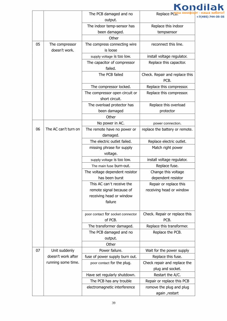
39
The PCB damaged and no
output.
Replace PCB.
The indoor temp-sensor has
been damaged.
Replace this indoor
tempsensor
Other
05 The compressor
doesn’t work.
The compress connecting wire
is loose
reconnect this line.
supply voltage is too low. install voltage regulator.
The capacitor of compressor
failed.
Replace this capacitor.
The PCB failed Check. Repair and replace this
PCB.
The compressor locked. Replace this compressor.
The compressor open circuit or
short circuit.
Replace this compressor.
The overload protector has
been damaged
Replace this overload
protector
Other
06
The AC can’t turn on
No power in AC. power connection.
The remote have no power or
damaged.
replace the battery or remote.
The electric outlet failed. Replace electric outlet.
missing phrase for supply
voltage.
Match right power
supply voltage is too low. install voltage regulator.
The main fuse burn-out. Replace fuse.
The voltage dependent resistor
has been burst
Change this voltage
dependent resistor
This AC can’t receive the
remote signal because of
receiving head or window
failure
Repair or replace this
receiving head or window
poor contact for socket connector
of PCB.
Check. Repair or replace this
PCB.
The transformer damaged. Replace this transformer.
The PCB damaged and no
output.
Replace the PCB.
Other
07 Unit suddenly
doesn’t work after
running some time.
Power failure. Wait for the power supply
fuse of power supply burn out. Replace this fuse.
poor contact for the plug. Check repair and replace the
plug and socket.
Have set regularly shutdown. Restart the A/C.
The PCB has any trouble Repair or replace this PCB
electromagnetic interference romove the plug and plug
again ,restart

40
Other
08
Can not heating and
cooling.
no refrigerant in system. Please fill up refrigerant.
The refrigerant leaked. refill up refrigerant after
checking the leak source.
Disconnecting valve dosen’t
turn on.
Please turn on disconnecting
valve.
The system is blocked. For
example the strainer or connect
pipe.
Replace this parts which
blocked.
The compressor failed. Replace the compressor.
no air from the outlet find out the cause ,replace the
motor ,capacitor,PCB,or do
other actions
Other
09
Noise and vibration
is existent during
running.
electromagnetic noise from
compressor. Replace this compressor.
resonance between the
compressor and other parts.
Add bumper block or adjust
the position
The indoor and outdoor motor
rusted or electromagnetic noise. Replace this motor.
The cross flow fan collides with
the slot basis Reconfigure.
The noise of the refrigerant
moving.
Readjust the position of the
H&L pressure pipe.
The screw of outdoor unit is
loose and caused the noise and
vibration.
crew down this screw.
The bearing of cross flow fan
broke. Replace the bearing.
The cross flow fan collides with
the foam or sponge
The pipe of outdoor unit contact
with crust
make the pipes well,keep the
suitable space(over 10mm)
The noise come from
synchronous motor, stepper
motor, capacitance,
transformer, reactor.
Replace them
the indoor and outdoor air
circulation channel is clogged,
which generated noise.
Clear the sundries
fan or blower damaged Replace it
Other
The drain pipe is jammed or
broken.
Clear up the stem or replace a
new pipe.
The installation of evaporator
and water receiving tank is not
in place.
reinstall them

41
10
Water leakage of
indoor unit
The outlet part broke. Paste new gland strip.
When bending tube of the
evaporator collides with the
PCB's wire, the condensed
water would flow along the
wire, and can't flow into the
receiving water tank.
Please avoid contacting
between the bending tube and
the PCB’s wire.
A lot of evaporator fins fall
down to lead to bad flow.
Renovate these faulty fins.
The indoor unit didn’t install
correctly according to the
requirement.
Please reinstall the indoor unit
correctly.
The damping rubber is shedding Put again
The drain pipe is shedding Fix again
The filter or evaporator is very
dirty
Clean it
refrigerant isn’t enough,cause
the evaporator ice,leak water
after off
Refill refrigerant

42
I. User’s Manual

43
The name of each part and its function

44
Remote controller

45
Use of remote controller
Operating machine in selected modes

46

47
Basic principles and performances
Features of Heating Operations
Methods of maintenance

48

49

50