>chigj8i>dc b6cj6a - northern tool - quality tools … · ing, drilling, and other ......
TRANSCRIPT


Some dust created by power sanding, sawing, grind-ing, drilling, and other construction activities con-tains chemicals known to the State of California to cause cancer, birth defects or other reproductive harm. Some examples of these chemicals are:
• Lead from lead-based paints. • Crystalline silica from bricks, cement, and other masonry products. • Arsenic and chromium from chemically treated lumber.
Your risk from these exposures varies, depending on how often you do this type of work. To reduce your exposure to these chemicals: work in a well venti-lated area, and work with approved safety equip-ment, such as those dust masks that are specially designed to filter out microscopic particles.

Woodstock Technical Support ............................................................................ 3About Your New 10" x 20" Lathe ......................................................................... 3Specifications ............................................................................................... 4
Standard Safety Instructions ............................................................................. 6Additional Safety Instructions for Lathes .............................................................. 8
110V Operation ............................................................................................. 9Extension Cords ............................................................................................ 9Grounding ................................................................................................... 9
Unpacking ................................................................................................. 10Inventory .................................................................................................. 10Machine Placement ...................................................................................... 11Cleaning Machine......................................................................................... 11Test Run .................................................................................................... 12
General .................................................................................................... 13Controls .................................................................................................... 13Removing/Installing Chuck or Faceplate ............................................................. 14Dead Centers ............................................................................................. 15Tailstock Positioning ..................................................................................... 16Changing Tool Posts ...................................................................................... 16Cross Slide ................................................................................................. 17Compound Slide .......................................................................................... 17Carriage .................................................................................................... 18Understanding Gear Charts ............................................................................. 19Changing Feed Rates .................................................................................... 22Reverse Threading ....................................................................................... 24Determining Correct Spindle Speed ................................................................... 25Changing Speeds ......................................................................................... 26
Checking V-Belt ........................................................................................... 27Lubrication ................................................................................................ 27Maintenance Schedule ................................................................................... 29Maintenance Notes ....................................................................................... 29
General .................................................................................................... 30Aligning Tailstock ......................................................................................... 30Gibs ......................................................................................................... 32Wiring Diagram ........................................................................................... 33Lathe Troubleshooting ................................................................................... 34

Bed/Body Breakdown .................................................................................... 36Bed/Body Parts List ...................................................................................... 37Headstock Breakdown ................................................................................... 38Headstock Parts List ..................................................................................... 39Tailstock Breakdown ..................................................................................... 40Tailstock Parts List ....................................................................................... 41Tool Post/Compound Slide Breakdown ................................................................ 42Tool Post/Compound Slide Parts List .................................................................. 43Cross Slide Breakdown .................................................................................. 44Cross Slide Parts List .................................................................................... 45Apron and Gearbox Breakdowns ....................................................................... 46Apron and Gearbox Parts Lists ......................................................................... 47Drive System Breakdown ................................................................................ 48Drive System Parts List .................................................................................. 49Warranty ................................................................................................... 50Warranty Registration ................................................................................... 51

-3-
Your new ® machine has been specially designed to provide many years of trouble-free ser-vice. Close attention to detail, ruggedly built parts and a rigid quality control program assure safe and reliable operation.
Woodstock International, Inc. is committed to customer satisfaction. Our intent with this manual is to include the basic information for safety, setup, operation, maintenance, and service of this product.
We stand behind our machines! In the event that questions arise about your machine, please contact Woodstock International Technical Support at (360) 734-3482 or send e-mail to:
. Our knowledgeable staff will help you troubleshoot problems and process warranty claims.
If you need the latest edition of this manual, you can download it from . If you have comments about this manual, please contact us at:

-4-
Type .............................................................................. TEFC Capacitor Start InductionHorsepower .................................................................................................... 3⁄4 HPSwitch .................................................................... Forward/Reverse w/ Emergency Stop Phase .................................................................................................... Single Phase Voltage ........................................................................................................... 110VAmps ................................................................................................................ 8 ARPM ......................................................................................................... 1725 RPM
Swing Over Bed ..................................................................................................9 3⁄4"Swing Over Saddle..................................................................................................6"Distance Between Centers ...................................................................................... 21''Compound Travel ................................................................................................2 1⁄4''Cross Slide Travel ................................................................................................4 1⁄4"Tailstock Barrel Travel ........................................................................................... 1⁄2"Spindle Speeds ............................................................ 150, 240, 490, 750, 1200, 2400 RPMFeed Rate Range .......................................................................... 2 @ 0.005" and 0.010"Thread Range Inch ............................................ 8-40 TPI in 12 Steps (Gear changes required)Thread Range Metric .............................................................................12 @ 0.4 – 3 mm
Overall Length .................................................................................................... 23"Overall Width ..................................................................................................... 44"Overall Height ................................................................................................. 171⁄2"Bed Width ....................................................................................................... 5 3⁄8"Spindle Bore ....................................................................................................... 3⁄4"Spindle Taper ........................................................................................Morse Taper #3Tailstock Taper ......................................................................................Morse Taper #2Weight (Net) ................................................................................................ 397 lbs. Crate Size .................................................................................... 51" L x 26" W x 32" HFootprint ................................................................................................. 161⁄2" x 43"
....................................................................................................... 5" 3-Jaw Chuck ......................................................................................................Cross Slide Table ......................................................................................................11 Change Gears ........................................................................................Quick Change Lathe Spindle ....................................................................................................... 2 Dead Centers ...............................................................................................4-Way Turret Tool Post ................................................................................Chuck Guard w/Automatic Shutoff

-5-
Thread Pitch Gearing & Speed Charts FWD/REV Switch ON/OFF, Emergency Stop Switch Power Indicator Light Lathe/Mill Selector Switch (for optional
milling head) Headstock Chuck Guard Lathe Chuck Carriage Feed Handwheel
Cross Slide Handwheel Carriage Feed Lever Compound Slide Turret Tool Post Compound Slide Handwheel Tailstock Clamp NutTailstock Axis Alignment IndicatorTailstock Quill Handwheel
Tailstock Quill Lock
12
4
5
67
8 9 10 11
12
13
1415
16
17
3

-6-
Learn the applications, limitations and potential hazards of this machine. Keep the manual in a safe and convenient place for future reference.
Clutter and inadequate lighting invite potential hazards.
If a machine is equipped with a three-prong plug, it must be plugged into a three-hole grounded electrical receptacle or grounded extension cord. If using an adapter to aid in accom-modating a two-hole receptacle, ground using a screw to a known ground.
Use safety glasses with side shields or safety goggles that meet the appropriate standards of the American National Standards Institute (ANSI).
Do not operate this machine in wet or open flame environments. Airborne dust particles could cause an explosion and severe fire hazard.
and in working condition.
before connecting power to machine.
free of clutter, grease, etc.
Visitors must be kept at a safe distance while operating unit.
with padlocks, master switches or by removing starter keys.
Indicates an imminently hazardous situation which, if not avoided, WILL result in death or serious injury.
Indicates a potentially hazardous situation which, if not avoided, COULD result in death or serious injury.
Indicates a potentially hazardous situation which, if not avoided, MAY result in minor or moderate injury.
This symbol is used to alert the user to useful information about proper operation of the equipment, and/or a situation that may cause damage to the machinery.

-7-
The machine will do a safer and better job at the rate for which it was designed.
Do not force machine or attachment to do a job for which it was not designed.
Do not wear loose clothing, neck ties, gloves, jewelry, and secure long hair away from moving parts.
Before turning the machine on, make it a habit to check that all adjusting keys and wrenches have been removed.
But if you must use one, examine the extension cord to ensure it is in good condition. Immediately replace a damaged extension cord. Always use an extension cord that uses a ground pin and connected ground wire. Use an extension cord that meets the amp rating on the motor nameplate. If the motor is dual voltage, be sure to use the amp rating for the voltage you will be using. If you use an extension cord with an undersized gauge or one that is too long, excessive heat will be generated within the circuit, increasing the chance of a fire or damage to the circuit.
at all times.
.
Wait until it comes to a complete stop before leaving the area.
Follow lubrication and accessory attachment instructions in the manual.
difficulties performing the intended operation, stop using the machine! Then contact our technical support or ask a qualified expert how the operation should be performed.
Develop good habits in your shop and safety will become second-nature to you.
, especially when cutting fumes can be inhaled. Make sure you know what type of metal and cutting fluid you will be exposed to and how to avoid contamination.

-8-
Do not clear chips by hand. Use a brush, and never clear chips while the lathe is turning.
Always select the right cutter for the job, and make sure they are sharp. The right tool decreases strain on the lathe components and provide a better finish.
Always remove chuck key. Never walk away from the lathe with the key in the chuck.
Make sure workpiece is properly held in chuck before starting lathe. A workpiece thrown from the chuck will severely injure you or a bystander.
Turn lathe before changing speeds. The lathe must be turned OFF and the spindle brought to a complete stop before changing gears.
Protect your hands and the precision ground ways by using a chuck cradle or piece of plywood over the ways of the lathe when installing chucks.
Make sure workpiece has adequate clearance before starting machine. Check tool and tool post clearance, chuck clearance, and saddle clearance before starting the lathe.
Always use the appropriate feed and speed rates. Using the correct speed increases operator control, which decreases the possibility of operator injury.
Never attempt to slow or stop the lathe chuck by using your hand.
Always shut the lathe before you leave it unattended. An unsupervised lathe that is running invites accidents.
Tie up long hair or ponytails, and secure or remove loose clothing to avoid entanglement with moving parts.
Release automatic feeds after completing a job. Automatic feeds left engaged leave little time for an unsuspecting operator to avoid a "crash" after turning the lathe .
Make sure no part of the tool, tool holder, compound slide, cross slide, or carriage will contact the chuck during operation.

-9-
When it is necessary to use an extension cord, use the following guidelines:
• Use cords rated for Standard Service.• Never exceed a length of 100 feet.• Use cords with 14 ga. wire or bigger.• Ensure cord has a ground wire and pin.• Do not use cords in need of repair.
This machine must be grounded! The electrical cord sup-plied with this machine comes with a grounding pin. Do not remove it. If your outlet does not accommodate a ground pin, have it replaced by a qualified electrician or have an appropriate adapter installed.
When using an adapter, the adapter must be grounded.
The Model M1016 operates at 110 volts. The motor supplied with your new lathe is rated at 3⁄4 HP and will draw approximately 8 amps. A 5-15 plug is included for your machine and is intended to be plugged into a matching 5-15 receptacle.
For 110V operation, only connect your machine to a cir-cuit that is protected by a 15 amp circuit breaker.
Typical 110V 3-prong plug and outlet.Keep in mind that a circuit being used by other machines
or tools at the same time will add to the total load being applied to the circuit. Add up the load ratings of all machines on the circuit. If the total amp load exceeds the rating of the circuit breaker or fuse, use a different circuit.
Using a circuit breaker rated higher than 15 amps will increase the risk of fire!

-10-
The Model M1016 has been carefully pack-aged for safe transporting. If you notice the machine has been damaged, please contact your authorized
dealer immediately.
Lathe unit out of box.
Lathe component inventory.
A
B C D
E
FG H I
J
K
L
The following is a description of the main components shipped with the ® Model M1016. Lay the components out to inventory them.
Lathe ........................................................1 External Jaws for 3-Jaw Chuck..........................3 Chuck Key ...................................................1 Fuses .........................................................2 Handles ......................................................2 Dead Center MT#2 .........................................1 Dead Center MT#3 .........................................1 Tool Post Wrench 8mm ...................................1
Hex Wrenches 3, 4, 5, 6mm .............................4 Wrenches 5.5/7, 8/10, 12/14, 17/19mm ..............4 Fixed Shaft Gear 40 .......................................1 Gears 40, 45, 48, 50, 60, 66, 68, 70, 70, 72, 75 ... 11
If any parts appear to be missing, examine the packag-ing carefully to be sure those parts are not among the packing materials. If any parts are missing, find the part number in the back of this manual and contact Woodstock International, Inc. at (360) 734-3482 or at
.

-11-
Your Model M1016 weighs 397 lbs. and has a 43" x 16 1⁄2" footprint. Make sure the workbench you place this machine on is strong enough to handle the weight of the machine and future workpieces. We recommend bolting your machine to the workbench for maximum stability.
Consider existing and anticipated needs, size of material to be processed through the machine, and space for auxiliary stands, work tables or other machinery when establishing a location for your Lathe.
Lighting should be bright enough to eliminate shadow and prevent eye strain.
Electrical circuits must be dedicated or large enough to handle amperage requirements. Outlets must be located near each machine, so power or extension cords are clear of high-traffic areas. Follow local electrical codes for proper installation of new lighting, outlets, or circuits.
The table and other unpainted parts of your Lathe are coated with a waxy grease that pro-tects them from corrosion during shipment. Clean this grease off with a solvent cleaner or citrus-based degreaser. DO NOT use chlorine-based solvents such as brake parts cleaner or acetone—if you happen to splash some onto a painted surface, you will ruin the finish.

-12-
Before continuing to , test run the lathe to make sure it runs properly. Read through this entire set of procedures before performing any of the steps. If you have any questions about the results of your test run, check the troubleshooting chart on or contact our tech support at (360) 734-3482 or at
.
Make sure the chuck key is NOT inserted in the chuck, and that the lathe chuck guard is in the down position. Make this step a habit that you per-form every time you start the lathe.
Familiarize yourself with the lathe controls shown in . Make sure the STOP button is all the way
down before continuing.
Clear all tools, components, packing material, etc. away from the cutterhead.
Plug the machine into the power outlet!
Move the carriage feed lever up to the disengage mode.
Turn the selector switch to the “CUTTING” position. The lathe power indicator light should light up.
If it is does not light up, unplug the machine and check the fuse, your power source, and the connections on the machine before attempting to start the lathe. Call our Tech Support department if you cannot easily resolve the issue.
Flip up the emergency stop button to reveal the red and green ON/OFF buttons, and press the green but-ton to turn the lathe .
Stand to the side of the chuck, turn the FWD/REV switch to the "FWD" position. If the carriage starts moving, immediately push the STOP button and disengage the carriage feed lever, then restart the lathe.
Allow the lathe to run for at least two full minutes to make sure it is running satisfactorily and the chuck is turning clockwise.
Main lathe controls for test run.
FWD/REV Switch
Carriage Feed Lever
Turn the FWD/REV switch to the cen-ter "O" position.
After the chuck has come to a com-plete stop, turn the FWD/REV switch to the "REV" position.
Allow the lathe to run for at least two full minutes to make sure it is running satisfactorily and the chuck is turning counterclockwise.
Turn the FWD/REV switch to the cen-ter "O" position.
After the lathe has come to a com-plete stop, engage the carriage handwheel, rotate the handwheel to center the carriage on the bed, then disengage the handwheel.
Engage the automatic carriage feed lever.
Turn the lathe .
Verify that the carriage moves along the bed, then press the emergency stop button to turn the lathe .
Disengage the feed lever.
ON/OFF Switch
Selector Switch
-13-
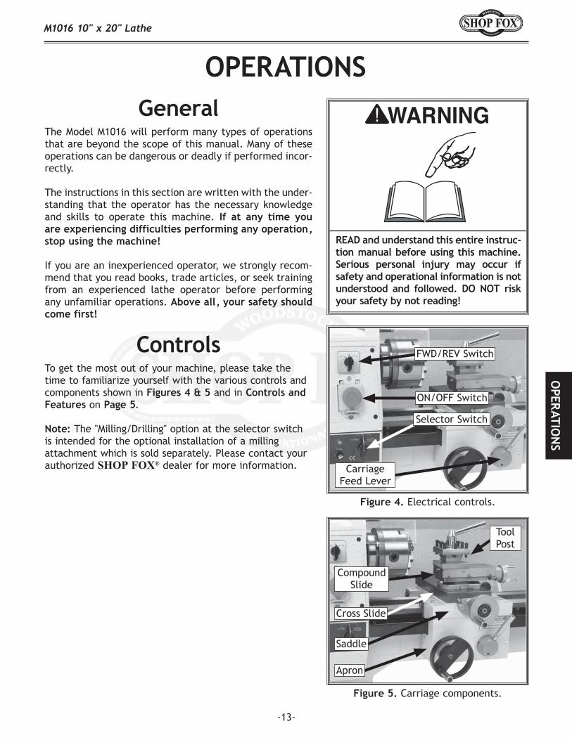
The Model M1016 will perform many types of operations that are beyond the scope of this manual. Many of these operations can be dangerous or deadly if performed incor-rectly.
The instructions in this section are written with the under-standing that the operator has the necessary knowledge and skills to operate this machine.
If you are an inexperienced operator, we strongly recom-mend that you read books, trade articles, or seek training from an experienced lathe operator before performing any unfamiliar operations.
To get the most out of your machine, please take the time to familiarize yourself with the various controls and components shown in and in
on .
The "Milling/Drilling" option at the selector switch is intended for the optional installation of a milling attachment which is sold separately. Please contact your authorized dealer for more information.
Electrical controls.
Carriage components.
FWD/REV Switch
Carriage Feed Lever
ON/OFF Switch
Selector Switch
Tool Post
Compound Slide
Cross Slide
Apron
Saddle

-14-
The Model M1016 spindle nose mounting system uses a circular lock plate with slotted holes that are oversized at one end (keyholes). When the lock plate is rotated coun-terclockwise (as facing the chuck), the studs with mount-ing nuts can pass through the spindle nose. When the lock plate is rotated toward the back of the lathe, the oversized holes narrow to the size of the studs, allowing the mounting nuts to be tightened against the back of the lock plate, thus, securing the chuck or faceplate.
Move the lathe chuck guard away from the chuck.
Familiarize yourself with the spindle nose compo-nents shown in .
Place a piece of plywood over the bed-ways to pro-tect your hands.
Hold the chuck/faceplate with your hand or a chuck key, and using a 17mm wrench, loosen the three chuck mounting nuts on the back of the knurled lock plate. DO NOT back the nuts out all the way or they will scratch the metal cover when you rotate the lathe chuck.
Rotate the lock plate toward the front of the lathe.
Remove the chuck/faceplate from the spindle nose by pulling it out ( ).
The tolerances are tight, so you may need to tap the chuck/faceplate with a rubber mallet, rotate it 1⁄4 of a turn, tap it, rotate it, and continue repeating this process until the chuck comes out. Never use a pry bar or steel hammer to remove the chuck or you will damage machine components!
Spindle nose components.
Lock Plate
Removing chuck from spindle nose.
Mounting Nuts

-15-
Insert the three mounting studs into the back of the chuck and tighten them down. If you are switching chucks, take the mounting studs out of the previ-ously removed chuck and use them in the chuck you are going to install. Also, make sure that a chuck mounting nut is on each of the studs.
Make sure that the knurled lock plate is rotated all the way toward the front of the lathe.
Insert the chuck onto the spindle nose.
Rotate the knurled lock plate toward the back of the lathe until it stops. If the lock plate will NOT rotate more than a fraction of an inch, then the chuck is not completely inserted. Make sure the chuck is completely inserted so the lock plate can be rotated properly.
Hold the chuck/faceplate with your hand or a key. Using a 17mm wrench, snug the three chuck mount-ing nuts to the back of the knurled lock plate, then final tighten all three with even pressure.
Remove all wrenches and chuck keys from the chuck/spindle nose.
Move the lathe chuck guard down over the chuck before operating, or the lathe will not start.
Familiarize yourself with the tailstock components shown in .
Make sure the dead center and tailstock quill are clean and free of any dirt, dust, grease, or oil. Morse tapers will not interlock when dirt or oil are present on the mounting surfaces.
Extend the quill approximately 1".
Slide the dead center into the tailstock quill as shown in .
Inserting dead center into tailstock quill.
Tailstock components.
Use the tailstock handwheel to move the tailstock quill all the way back into the tailstock until the handwheel will no longer turn (this will push the dead center out of the quill).
Pull the dead center out of the tailstock quill.
Quill Lock
Quill Handwheel

-16-
Using a 17mm wrench, loosen the tailstock clamp nut shown in .
Slide the tailstock into position along the bed, then tighten the clamp nut to secure the tailstock in the new position.
The two offset adjustment screws ( ) position the tailstock away from the center line for turning tapers.
Loosen the tailstock clamp nut, and using a 3mm hex wrench, loosen the lock screw.
Using a 6mm hex wrench, loosen the front offset adjustment screw.
Tighten the rear offset adjustment screw to move the tailstock to the desired position, then tighten the front offset adjustment screw.
Tighten the lock screw and clamp nut.
Tailstock positioning controls.
Rotate the tool post lock handle counterclockwise to remove it as in .
Pull the installed tool post straight up to remove it from the compound slide.
Install the new tool post on the compound slide, and position it to the intended working angle.
Tighten the tool post in place with the lock handle. shows a quick change tool post correctly
installed.
Removing tool post lock handle.
Optional quick change tool post installed.
Clamp Nut
Lock ScrewFront Offset Adj. Screw
Rear Offset Adj. Screw (Behind the Casting)
-17-
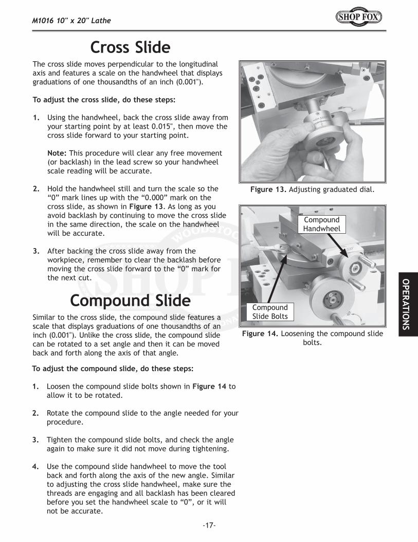
The cross slide moves perpendicular to the longitudinal axis and features a scale on the handwheel that displays graduations of one thousandths of an inch (0.001").
Using the handwheel, back the cross slide away from your starting point by at least 0.015", then move the cross slide forward to your starting point.
This procedure will clear any free movement (or backlash) in the lead screw so your handwheel scale reading will be accurate.
Hold the handwheel still and turn the scale so the “0” mark lines up with the “0.000” mark on the cross slide, as shown in . As long as you avoid backlash by continuing to move the cross slide in the same direction, the scale on the handwheel will be accurate.
After backing the cross slide away from the workpiece, remember to clear the backlash before moving the cross slide forward to the “0” mark for the next cut.
Adjusting graduated dial.
Loosening the compound slide bolts.
Similar to the cross slide, the compound slide features a scale that displays graduations of one thousandths of an inch (0.001"). Unlike the cross slide, the compound slide can be rotated to a set angle and then it can be moved back and forth along the axis of that angle.
Loosen the compound slide bolts shown in to allow it to be rotated.
Rotate the compound slide to the angle needed for your procedure.
Tighten the compound slide bolts, and check the angle again to make sure it did not move during tightening.
Use the compound slide handwheel to move the tool back and forth along the axis of the new angle. Similar to adjusting the cross slide handwheel, make sure the threads are engaging and all backlash has been cleared before you set the handwheel scale to “0”, or it will not be accurate.
Compound Slide Bolts
Compound Handwheel

-18-
Carriage controls.
Like most lathes, the longitudinal movement of the car-riage (carriage feed) on the Model M1016 can be con-trolled both manually and automatically. Before proceed-ing, take a closer look at the carriage controls shown in
.
Push the carriage feed handwheel toward the car-riage to engage the gear on the lead screw.
Rotate the handwheel clockwise to move the car-riage right and rotate the handwheel counterclock-wise to move the carriage left.
Set the handwheel scale in the same manner as described in the “Adjusting Cross Slide” instructions, and be sure to account for the backlash.
Select the desired feed rate you need by looking at the charts on the lathe drive cover. (The Model M1016 is geared from the factory for a carriage feed rate of 0.005" per revolution.) Refer to for instructions on changing the feed rate.
Use the manual feed handwheel to position the car-riage to your desired starting point and set the scale on the handwheel to “0”.
Move the carriage feed lever down to engage the half-nut, which in turn, makes the automatic car-riage feed active.
Pull out the carriage manual feed handwheel to unlock it so it does not rotate when the automatic carriage feed is engaged.
The carriage feed will now move forward or backward, depending on which direction you have selected for lathe rotation.
Carriage Feed Engage Position
Carriage Handwheel
Carriage Feed Lever
Carriage Feed Disengage Position
-19-
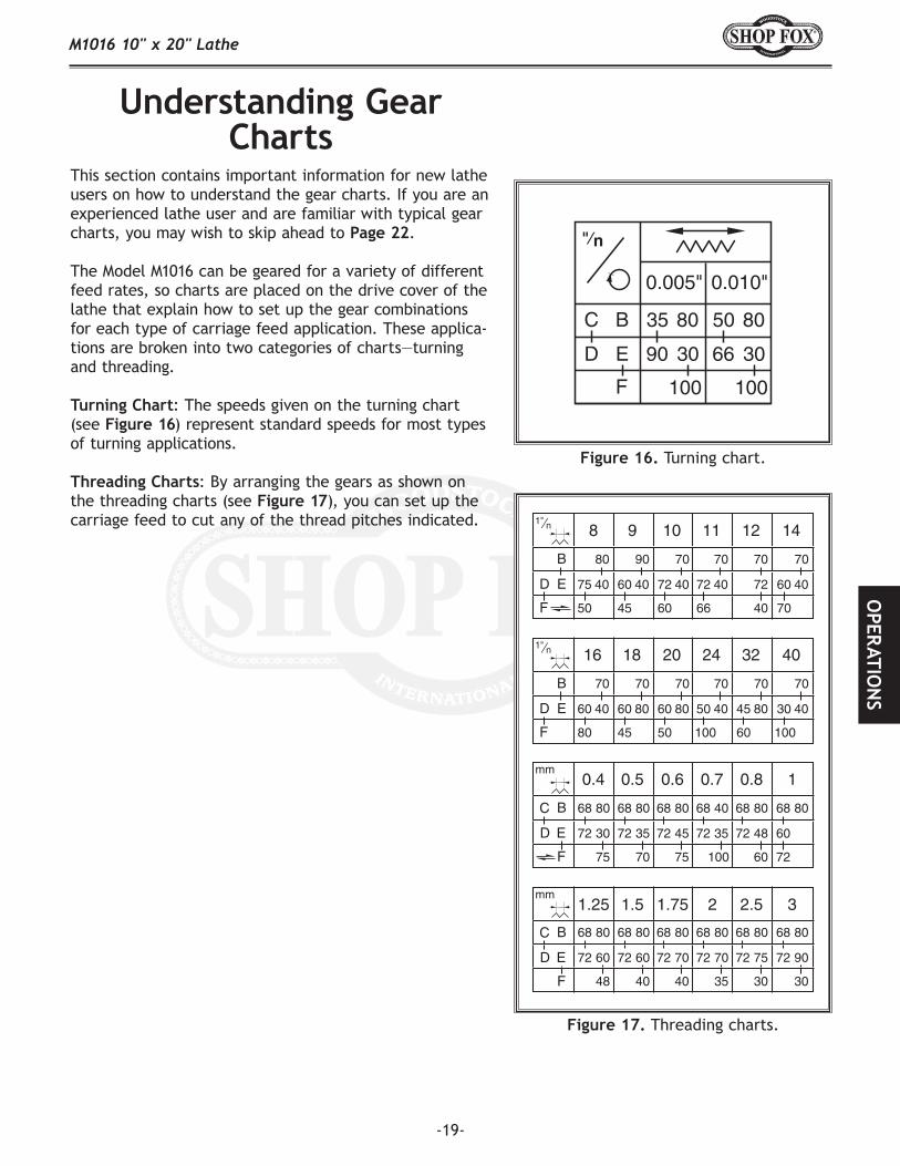
This section contains important information for new lathe users on how to understand the gear charts. If you are an experienced lathe user and are familiar with typical gear charts, you may wish to skip ahead to .
The Model M1016 can be geared for a variety of different feed rates, so charts are placed on the drive cover of the lathe that explain how to set up the gear combinations for each type of carriage feed application. These applica-tions are broken into two categories of charts—turning and threading.
: The speeds given on the turning chart (see ) represent standard speeds for most types of turning applications.
: By arranging the gears as shown on the threading charts (see ), you can set up the carriage feed to cut any of the thread pitches indicated.
Turning chart.
Threading charts.

-20-
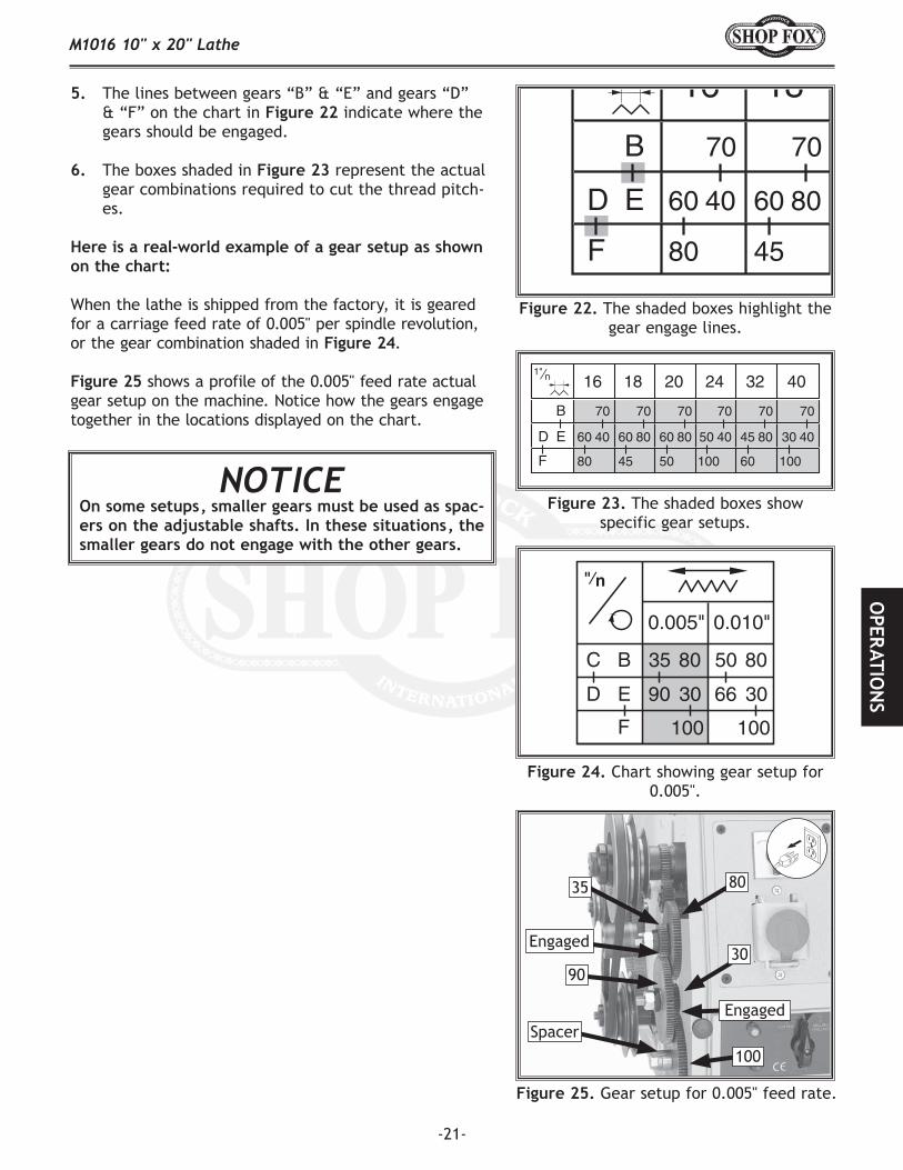
The box in the upper left-hand corner of each chart tells whether that chart represents carriage feed movement for standard or metric threads. These boxes are shaded in .
The boxes in the top row of each chart (excluding the box in the left-hand corner) shows the thread pitches listed on that chart. These boxes are shaded in .
The boxes on the left-hand column (excluding the box in the upper left-hand corner) represent the gear positions on each shaft. These boxes are shad-ed in and the shafts are called out with arrows.
Each shaft has room for two positions to mount the gears—a forward position and a rear position.
separates these positions into different shades for you to understand better.
Both forward and rear positions must be filled on the shaft in order for the gears to work properly. A good example of this is the blank spot to the right of gear “F,” as shown in the chart in .
Although the chart shows this as a blank spot, there should actually be a spacer in this position on the machine. This spacer is not listed on the chart, because the chart only reflects ACTIVE gear posi-tions.
Smaller gears can be used as spacers.
The shaded boxes indicate whether threads are standard or metric.
The shaded boxes show the thread pitches listed on this chart.
The shaded boxes show which gears need to be on which shafts.
The shaded boxes show the rear and forward positions on each shaft.
Continued on next page
-21-
The shaded boxes highlight the gear engage lines.
The shaded boxes show specific gear setups.
Chart showing gear setup for 0.005".
Gear setup for 0.005" feed rate.
The lines between gears “B” & “E” and gears “D” & “F” on the chart in indicate where the gears should be engaged.
The boxes shaded in represent the actual gear combinations required to cut the thread pitch-es.
When the lathe is shipped from the factory, it is geared for a carriage feed rate of 0.005" per spindle revolution, or the gear combination shaded in .
shows a profile of the 0.005" feed rate actual gear setup on the machine. Notice how the gears engage together in the locations displayed on the chart.
Spacer
Engaged
90
35 80
30
Engaged
100
-22-
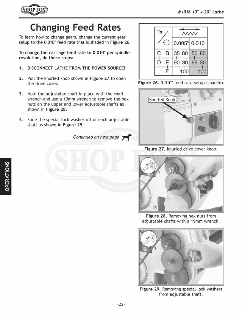
To learn how to change gears, change the current gear setup to the 0.010" feed rate that is shaded in .
Pull the knurled knob shown in to open the drive cover.
Hold the adjustable shaft in place with the shaft wrench and use a 19mm wrench to remove the hex nuts on the upper and lower adjustable shafts as shown in .
Slide the special lock washer off of each adjustable shaft as shown in .
0.010" feed rate setup (shaded).
Knurled drive cover knob.
Removing hex nuts from adjustable shafts with a 19mm wrench.
Removing special lock washers from adjustable shaft.
Knurled Knob
Continued on next page

-23-
Using the shaft wrench, loosen the upper and lower adjustable shafts as shown in . DO NOTloosen them too much or the T-nut will fall out and you will have to remove the gear bracket to recon-nect the adjustable shaft to the clamp nut.
Using the 5mm hex wrench, loosen the cap screw on the gear bracket as shown in .
Pivot the gear bracket away from the drive gear as shown in .
Slide the gears on the upper adjustable shaft to the top of the gear bracket, and hand tighten the shaft to keep it from engaging with the gears on the lower shaft.
Remove the 35T and 90T gears (those in the forward position on each adjustable shaft).
Install the 50T gear on the upper adjustable shaft and place the 66T gear on the lower adjustable shaft.
When placing the gear on the lower adjust-able shaft, slide it up or down to make it engage with the gear on the pivot shaft.
Replace the remaining gear components as they were removed, engage all the gears together, and tighten the adjustable shafts and bracket cap screw.
Leave a small amount of backlash where the gears engage to avoid binding or noisy operation.
Turn the the chuck by hand to make sure that all the gears turn smoothly.
Close and secure the drive cover.
Test run the lathe to make sure it works properly before continuing with your specific operation.
Using shaft wrench to loosen adjustable shafts.
Loosening gear bracket cap screw.
Gear bracket pivoted away.

-24-
The Model M1016 can be setup to turn left-handed threads by adding another fixed-shaft gear and moving the original fixed-shaft gear to another mounting loca-tion. shows the three mounting locations for fixed-shaft gears (spindle drive pulley is removed for clar-ity). For illustration purposes, we label these mounting positions A, B & C.
Locate the extra fixed-shaft gear (shown in ) in your inventory of loose parts.
Thread the extra fixed-shaft gear into mounting location “A” as shown in .
When the machine is shipped, a fixed-shaft gear is in position “B.” Remove that fixed-shaft gear from mounting location “B” and thread it into mounting location “C” as shown in .
Loosen the cap screw on the gear bracket, and pivot the bracket so the top gear engages with the fixed-shaft gear in position “C,” as shown in .
Tighten the cap screw in the gear bracket to keep it from pivoting.
Spin the lathe chuck by hand to ensure that the gears do not bind. (If the gears do bind, loosen them and re-engage together without as much pressure.)
Replace the cover and test run the machine before proceeding with your specific operation.
Fixed-shaft gear mounting positions.
Extra fixed-shaft gear.
Extra fixed-shaft gear mounted in position “A.”
All gears engaged for reverse threading operations.
Fixed-shaft gear mounted in position “C.”
A
B
C
A
C

-25-
Use the table below to determine the cutting speed required for the material of your workpiece.
Measure the diameter of your workpiece in inches and subtract the depth of the cut that will be taken on the initial pass.
Use the formula in to determine the needed RPM for your operation.
Always round to the closest RPM given on the spindle speed chart, and adjust your speed as the workpiece diameter decreases.
You have a piece of 1⁄2" diameter aluminum stock, and you are using workpiece with a HSS cutting tool.
300 (SFM from chart) x 4 = 1200 1200 / 0.5" (Diameter of workpiece) = 2400 RPM
The needed speed for this workpiece is 2400 RPM.
You have a piece of 1" diameter stainless steel stock, and you are using a workpiece with a car-bide cutting tool.
60 (SFM from chart) x 2 (for carbide tool) = 120
120 (determined SFM) x 4 = 480
480 / 1" (Diameter of workpiece) = 480 RPM
The needed speed for this workpiece is 480 RPM.
Cutting speed chart for HSS cutting tools.
Formula to determine required spindle speed for lathes.
Cutting Speeds for High Speed Steel (HSS) Cutting Tools*
Workpiece Material Cutting Speed (SFM)
Aluminum & Alloys 300
Brass & Bronze 150
Copper 100
Cast Iron, soft 80
Cast Iron, hard 50
Mild Steel 90
Cast Steel 80
Alloy Steel, hard 40
Tool Steel 50
Stainless Steel 60
Titanium 50
Plastics 300-800
Wood 300-500*For carbide cutting tools, double the cutting speed. These values are a guideline only. Refer to the current edition of for more detailed information.

-26-
The Model M1016 features 6 speeds—150, 240, 490, 750, 1200 and 2400 RPM. These speeds can be changed by positioning the V-belt in different sheaves on the drive pulleys, as illustrated in the speed change chart on the machine label or in .
Remove the drive belt cover.
Using a 19mm wrench, loosen the bolt on the tensioner bracket (shown in ).
Move the pulley bracket away from the belt.
Position the belt into the pulley sheaves that dictate the speed required for your operation.
Move the pulley bracket into the belt and tension it until there is about 1⁄2" deflection on the side of the belt opposite of where the tensioner is making contact. shows how to check for proper tension by using a ruler and your thumb.
Only moderate pressure is needed to check belt tension!
Replace the drive belt cover.
Speed change chart.
Tensioner adjustment bolt.
Checking for proper V-belt tension.

-27-
For lubricating your machine, we recommend that you use a manual oiler (oil can) filled with ISO 68 or SAE 20W non-detergent oil or similar lubricant.
—Shown in , ball fittings are responsible for the majority of the machine lubrication. To lubricate ball fittings, press the ball with the tip of the oil can nozzle and squirt a little oil inside the fitting. Make sure to clean the outside of the ball fitting before and after each use to keep out contaminants.
To ensure optimum power transmission from the motor, the V-belts must be in good condition and must operate under proper tension. The belts should be checked for cracks, fraying, and wear at least every 3 months—more often if the machine is used daily.
Open the drive cover.
Note the condition of the V-belt. If the V-belt is cracked, frayed, or glazed; it should be replaced.
Check the belt tension as shown in .
Checking for proper V-belt tension.
Lubrication ball fittings.
Continued on next page

-28-
—Lubricate the following areas every 8 hours of actual use:
Left Leadscrew Support Compound Slide Compound Slide Leadscrew Tailstock Quill Tailstock Leadscrew Right Leadscrew Support Fixed-Shaft Gear Synchronized Counter Pulley Upper Adjustable Shaft Lower Adjustable Shaft Pivot Shaft Bed Guide Cross Slide Leadscrew Cross Slide Bed Guide Apron Cross Slide Leadscrew Support Apron Bed Guide Cross Slide Bed Guide
—Apply a minimal amount of oil to the teeth of the end gears after assembly and each 8 hours of actual use. Avoid getting oil on the belt or pulleys when lubricating. Also, regularly apply lubrication to all the ball fittings in the drive box.
—Apply a minimal amount of white lithium grease directly on the leadscrew every 8 hours of actual use.
—Apply a minimal amount of white lithium grease directly on the leadscrew every 8 hours of actual use.
Ball fitting lubrication points.
Ball fitting lubrication points.
Ball fitting lubrication points.
1
23
6
45
7
8
9
10
11
12
13
14
15
3
16
21
20
19
18
17

-29-

-30-
This section covers the most common service adjustments or procedures that may need to be made during the life of your machine.
If you require additional machine service not included in this section, please contact Woodstock International Technical Support at (360) 734-3482 or send e-mail to:
.
The tailstock on the Model M1016 is aligned with the headstock at the factory. However, at times you may wish to misalign the tailstock for certain operations; then, realign it when you are finished.
Center drill a 6'' long piece of round stock on both ends. Set it aside for use in .
Make a dead center by turning a shoulder to make a shank, then flip the piece over in the chuck and turn a 60° point, as illustrated in .
As long as it remains in the chuck, the point of your center will be accurate to your spindle axis. Keep in mind that the point will have to be refin-ished whenever it is removed and returned to the chuck.
Place a center in your tailstock.
Attach a lathe dog to the bar stock and mount it between the centers, as shown in .
Turn approximately 0.010" off of the diameter of the piece of bar stock.
Finished dead center.
Bar stock mounted on centers.

-31-
Measure the newly turned bar stock with a microm-eter.
• If the stock is fat at the tailstock end, the tailstock needs to be moved toward you the amount of the taper, as shown in .
• If the stock is thinner at the tailstock end, the tailstock needs to be moved away from the opera-tor by at least the amount of the taper, as shown in .
Loosen the clamp nut and the lock screw shown in .
Use the offset adjustment screws on both sides to adjust move the tailstock offset. (Refer to for more details on offset positioning.)
Tighten the clamp nut, lock screw and adjustment screws. Be careful not to move the tailstock out of position when tightening the adjustment screws.
Turn another 0.010'' off of the stock and check for taper. Repeat as necessary until the desired amount of accuracy is achieved.
Adjusting for headstock end taper.
Adjusting for tailstock end taper.
Tailstock offset adjustment controls.
Move tailstock forward half the
amount of the taper
VIEWED FROM ABOVE
Move tailstock backward half the
amount of the taper
VIEWED FROM ABOVE
Lock ScrewFront Offset Adj. Screw
Rear Offset Adj. Screw (Behind the Casting)
Clamp Nut

-32-
Cross slide gib screws.
Compound slide gib screws.
Front saddle gib screws.
Rear saddle gib screws.
There are three gib adjustments for the Model M1016—the cross-slide gib, the compound slide gib, and the saddle gib.
—The gib on the cross-slide is adjusted by tightening or loosening the four gib screws located on the right-hand side of the slide (shown in ). Before adjusting the gib screws, loosen their jam nuts.
The gib is held in place by the setscrews. DO NOT over-tighten. The gib is properly adjusted when a slight drag is detected while turning the hand crank. This drag should be evenly distributed among the 4 setscrews, so adjust each screw evenly.
—The gib on the compound has three screws that maintain tension on the slide (see
). These screws are held in place with retaining nuts. To adjust, loosen the retaining nuts and then tighten the screws evenly to achieve a slight drag when turning the hand crank. When proper tension has been achieved, tighten the retaining nuts while maintaining the position of the screw with a hex wrench.
—There are four tensioning screws for both the front and rear saddle gibs (see . Before making adjustments to the saddle gib, ensure that the front lock lever is loose by turning it counter-clockwise. It is important that the screws are tightened evenly. A slight drag should be detected while turning the hand crank at the end of the lathe.

-33-

-34-
This section covers the most common problems and corrections with this type of machine.
Motor will not start. 1. Chuck guard is up.
2. Tripped circuit breaker or blown fuse at power supply box or machine electrical box.
3. Open circuit in motor or loose connections.
4. Low voltage.5. Faulty start capacitor.
1. Put chuck guard down; machine will not run with chuck guard up.
2. Reset the tripped circuit breaker or replace the blown fuse.
3. Inspect all lead connections on motor and magnetic switch for loose or open connections.
4. Check power supply for proper voltage. 5. Replace start capacitor.
Fuses blow or circuit breakers trip open.
1. Short circuit in line cord or plug.
2. Short circuit in motor or loose connections.
3. Incorrect fuses or circuit breakers in power supply.
1. Inspect cord or plug for damaged insulation and shorted wires and replace extension cord.
2. Inspect all connections on motor for loose or shorted terminals or worn insulation.
3. Install correct fuses or circuit breakers.
Motor overheats. 1. Motor overloaded by depth of cut, feed rate, incorrect spindle speed, or dull cutter.
2. Low power supply voltage.
3. Air circulation through the motor restricted.
1. Reduce load on motor by reducing depth of cut, reducing feed rate, using the correct spindle speed, and using a sharp cutter.
2. Correct the low voltage condition with a qualified electrician; make sure extension cord is not used.
3. Clean out motor to provide normal air circulation.
Motor automatically shuts off.
1. Blown fuse, possibly from overloading motor during operation.
2. Short circuit in motor or loose connections.
3. Incorrect fuses/circuit breakers.4. Low power supply voltage.
1. Replace the fuse and avoid overloading the motor during operation.
2. Inspect connections on motor for loose or shorted terminals or worn insulation.
3. Install correct fuses or circuit breakers.4. Correct the low voltage condition with a qualified
electrician; make sure extension cord is not used.
Loud, repetitious noise coming from machine at or near the motor.
1. Pulley setscrews or keys are missing or loose.
2. Motor fan is hitting the cover.
1. Inspect keys and setscrews. Replace or tighten if necessary.
2. Tighten fan or shim cover, or replace items.
Motor is loud when cutting. Overheats or bogs down in the cut.
1. Excessive depth of cut or feed rate.
2. Turning speed too high.
3. Cutting tool is dull.4. Gear setup is too tight, causing
them to bind.
1. Decrease depth of cut or feed rate.
2. Use the recommended spindle speed (see ).
3. Sharpen or replace the cutting tool.4. Readjust the gear setup with a small amount of
backlash so the gears move freely and smoothly when the chuck is rotated by hand.

-35-
Entire machine vibrates excessively upon startup and while running.
1. Workpiece is unbalanced.
2. Loose or damaged belt(s).3. V-belt pulleys are not properly
aligned.4. Worn or broken gear present.5. Chuck or faceplate has become
unbalanced.6. Spindle bearings badly worn.
1. Reinstall workpiece so it is as centered with the spindle bore as possible.
2. Tighten/replace the belt as necessary.3. Align the V-belt pulleys.
4. Inspect gears and replace if necessary.5. Rebalance chuck or faceplate; contact a local
machine shop for help.6. Replace spindle bearings.
Tailstock quill will not feed out of tailstock.
1. Quill lock is tightened down. 1. Unlock.
Bad surface finish. 1. Wrong RPM or feed rate.2. Dull tooling or poor tool selection.
3. Too much play in gibs.4. Tool too high.
1. Adjust for appropriate RPM and feed rate.2. Sharpen tooling or select a better tool for the
intended operation.3. Tighten gibs.4. Lower the tool position.
Can't remove tapered tool from tailstock quill.
1. Quill had not retracted all the way back into the tailstock.
2. Debris was not removed from taper before inserting into quill.
1. Turn the quill handwheel until it forces taper out of quill.
2. Always make sure that taper surfaces are clean.
Cross slide, compound slide, or carriage feed has sloppy operation.
1. Gibs are out of adjustment.2. Handwheel is loose.3. Lead screw mechanism worn or
out of adjustment.
1. Tighten gib screw(s) (see ).2. Tighten handwheel fasteners.3. Tighten any loose fasteners on lead screw mecha-
nism.
Cross slide, compound slide, or carriage feed handwheel is hard to move.
1. Gibs are loaded up with shavings, dust, or grime.
2. Gib screws are too tight.3. Backlash setting too tight (cross
slide only).
4. Bedways are dry.
1. Remove gibs, clean ways/dovetails, lubricate, and readjust gibs.
2. Loosen gib screw(s) slightly, and lubricate bedways.3. Slightly loosen backlash setting by loosening the
locking screw and adjusting the spanner ring at the end of the handle.
4. Lubricate bedways and handles.
Cutting tool or machine components vibrate exces-sively during cutting.
1. Tool holder not tight enough.2. Cutting tool sticks too far out of
tool holder; lack of support.3. Gibs are out of adjustment.
4. Dull cutting tool.5. Incorrect spindle speed or feed
rate.
1. Check for debris, clean, and retighten.2. Reinstall cutting tool so no more than 1/3 of the
total length is sticking out of tool holder.3. Tighten gib screws (see ) at affected com-
ponent.4. Replace or resharpen cutting tool.5. Use the recommended spindle speed (see
).
Inaccurate turning results from one end of the workpiece to the other.
1. Headstock and tailstock are not properly aligned with each other.
1. Realign the tailstock to the headstock spindle bore center line (see ).
Chuck jaws won't move or don't move easily.
1. Chips lodged in the jaws. 1. Remove jaws, clean and lubricate chuck threads, and replace jaws.
Carriage won't feed. 1. Gears are not all engaged.2. Gears are broken.3. Loose screw on the feed handle.
1. Adjust gear positions.2. Replace.3. Tighten.

-36-

-37-
REF PART�# DESCRIPTION REF PART�# DESCRIPTION1 XPS05M PHLP�HD�SCR�M5-.8�X�8 29 XPS30M PHLP�SCR�M8-1.25�X�152 XM1016002 LEADSCREW�COVER 30 XPW01M FLAT�WASHER�8MM3 XPR02M EXT�RETAINING�RING�14MM 31 XPSB14M CAP�SCREW�M8-1.25�X�204 XM1016004 CHANGE�GEAR�SPACER 32 XM1016032 RACK5 XM1016005 SMALL�GEAR 33 XPS08M PHLP�HD�SCR�M5-.8�X�126 XPK04M KEY�4�X�4�X�8 34 XM1016034 LEADSCREW�SUPPORT�R7 XM1016007 CHANGE�GEAR�SHAFT 35 XM1016035 LONG�LEADSCREW8 XPSB16M CAP�SCREW�M4-.7�X�16 36 XPRP56M ROLL�PIN�4�X�259 XM1016009 ADJUSTING�DISC 37 XM1016037 SLEEVE�JOINT10 XM1016010 SHAFT�SUPPORT 38 XM1016038 JOINT�SHAFT11 XM1016011 TAPER�PIN��6�X�26 46 XPB35M HEX�BOLT�M12-1.75�X�40��12 XPSB15M CAP�SCREW�M5-.8�X�20 47 XPW06M FLAT�WASHER�12MM13 XM1016013 BOLT�(WITH�SHOULDER) 48 XPK37M KEY�4�X�4�X�1614 XM1016014 OIL�CUP�6MM 54 XPS56M PHLP�HD�SCR�M4-.7�X�1615 XM1016015 BLOCK�FOR�SWITCH 55 XM1016055 SMALL�GEAR�PROTECTOR16 XPS07M PHLP�HD�SCR�M4-.7�X�8 56 XM1016056 GREEN�LAMP17 XM1016017 LEADSCREW�SUPPORT�L 57 XM1016057 FUSE�BOX18 XPS07M PHLP�HD�SCR�M4-.7�X�8 58 XM1016058 FUSE��19 XM1016019 ROUND�NUT 59 XM1016059 SELECTOR�SWITCH20 XM1016020 STEEL�WASHER 60 XPAW03M HEX�WRENCH�3MM21 XPS57M PHLP�HD�SCR�M5-.8�X�14 61 XPAW04M HEX�WRENCH�4MM22 XM1016022 SWITCH�LABEL 62 XPAW05M HEX�WRENCH�5MM23 XM1016023 SHAFT�COVER 63 XPAW06M HEX�WRENCH�6MM24 XM1016024 BED 64 XM1016064 WRENCH�5.5�X�725 XPN01M HEX�NUT�M6-1.0 65 XPWR810 WRENCH�8�X�1026 XPW03M FLAT�WASHER�6MM 66 XPWR1214 WRENCH�12�X�1427 XPSB04M CAP�SCREW�M6-1�X�10 67 XPWR1719 WRENCH�17�X�1928 XM1016028 SPLASH�GUARD
-38-

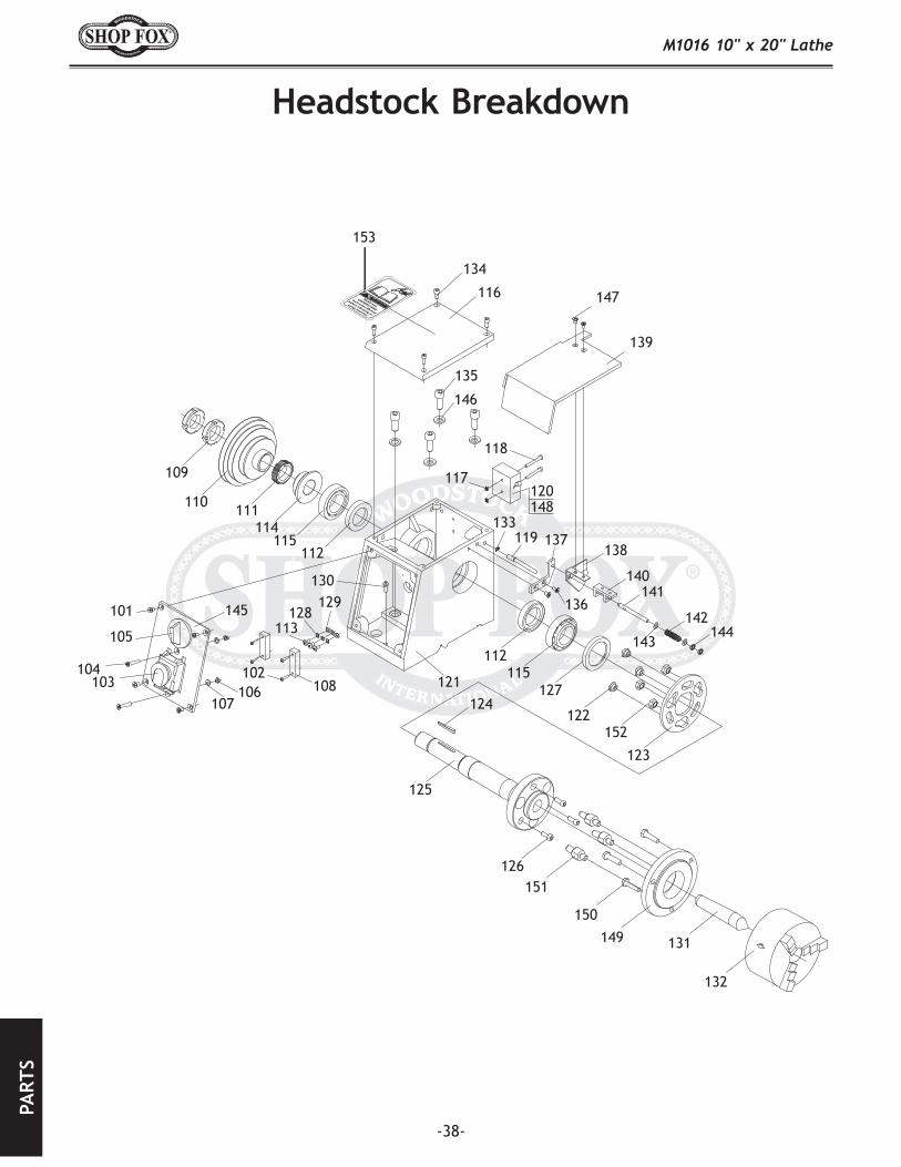
-39-
REF PART�# DESCRIPTION REF PART�# DESCRIPTION101 XPFH07M FLAT�HD�SCR�M5-.8�X�10 128 XPLW01M LOCK�WASHER�5MM102 XPS59M PHLP�HD�SCR�M3-.5�X�14 129 XPTLW02M EXT�TOOTH�WASHER�M5103 XM1016103 POWER�SWITCH�W/STOP 130 XPS40M PHLP�HD�SCR�M5-0.8�X�16104 XPFH45M FLAT�HD�SCR�M5-.8�X�30 131 XM1016131 SPINDLE�CENTER�MT3105 XM1016105 FWD/REV�SWITCH 132 XM1016132 3-JAW�CHUCK�D-125MM106 XPN06M� HEX�NUT�M5-0.8 133 XPR04M EXT�RETAINING�RING�6MM107 XPW02M� FLAT�WASHER�5MM 134 XPSB33M CAP�SCREW�M5-.8�X�12108 XM1016108 CONNECTOR 135 XPSB64M CAP�SCREW�M10-1.5�X�25109 XM1016109 ROUND�NUT��M27-1.5� 136 XPS09M PHLP�HD�SCR�M5-.8�X�10110 XM1016110 SPINDLE�PULLEY 137 XM1016137 SUPPORT111 XM1016111 SPINDLE�GEAR 138 XM1016138 LIMIT�BLOCK112 XM1016112 OIL�RING 139 XM1016139 CHUCK�GUARD113 XPS05M PHLP�HD�SCR�M5-.8�X�8 140 XM1016140 FIXING�SUPPORT114 XM1016114 SPINDLE�SPACER 141 XM1016141 SMALL�SHAFT115 XP32007 BEARING�32007 142 XM1016142 COMPRESSION�SPRING116 XM1016116 SPINDLE�BOX�COVER 143 XPW03M� FLAT�WASHER�6MM117 XPN04M� HEX�NUT�M4-0.7 144 XPN01M� HEX�NUT�M6-1.0118 XPSB22M CAP�SCREW�M4-.7�X�35 145 XM1016145 PLATE�FOR�SWITCHES119 XM1016119 PIN�SHAFT 146 XPW04M FLAT�WASHER�10MM��120 XM1016120 BOX�FOR�MICRO�SWITCH 147 XPS05M PHLP�HD�SCR�M5-.8�X�8121 XM1016121 HEAD�STOCK�BODY 148 XM1016148 MICROSWITCH122 XM1016122 FIXING�NUT 149 XM1016149 3-JAW�CHUCK�FLANGE123 XM1016123 ROTATABLE�SPACER 150 XM1016150 HEX�BOLT�M8-1.25�X�30124 XPK68M KEY�4�X�4�X�40 151 XM1016151 PLUG�BOLT125 XM1016125 SPINDLE 152 XPN02M HEX�NUT�M10-1.5126 XPSB01M CAP�SCREW�M6-1�X�16 153 XLABEL08 READ�MANUAL�LABEL127 XM1016127 FRONT�BEARING�COVER

-40-

-41-
REF PART�# DESCRIPTION201 XPSB13M CAP�SCREW�M8-1.25�X�30202 XM1016202 TAILSTOCK�T-NUT203 XPW06M FLAT�WASHER�12MM204 XPN09M HEX�NUT�M12-1.75205 XM1016205 TAILSTOCK�BODY206 XP51101 BEARING��51101��207 XM1016207 TAILSTOCK�LEADSCREW208 XM1016208 TAILSTOCK�SLEEVE209 XM1016209 TUBULAR�CLAMP210 XPW01M FLAT�WASHER�8MM211 XM1016211 CLAMP�BOLT212 XM1016212 HANDLE213 XM1016213 OIL�CUP214 XM1016214 T-TAP�FLAT�KEY215 XPSS11M SET�SCREW�M6-1�X�16216 XPSB15M CAP�SCREW�M5-.8�X�20217 XM1016217 TAILSTOCK�END�COVER218 XM1016218 CYLINDER�PIN�4�x�30219 XM1016219 BOW-TYPE�LEAF�SPRING220 XM1016220 HAND�WHEEL221 XM1016221 HANDLE�BOLT222 XM1016222 HANDLE�SLEEVE223 XM1016223 INDEX�RING224 XM1016224 SQ�BOLT�M12-1.75�X�100225 XM1016225 TAILSTOCKCLAMP�PLATE226 XM1016226 BASE227 XM1016227 ZERO�POSITION�LABEL228 XM1016228 LABEL�RIVET229 XM1016229 INDICATOR�LABEL230 XM1016230 TAILSTOCK�CENTER�MT#2

-42-

-43-
REF PART�# DESCRIPTION301 XM1016301 CUTTER�REST�BASE302 XM1016302 CLAMP�DISC303 XPB09M HEX�BOLT�M8-1.25�X�20304 XM1016304 CUTTER�REST�DISC��305 XM1016305 CUTTER�REST�BOLT306 XPN04M HEX�NUT�M4-0.7307 XPSS50M SET�SCREW�M4-.7�X�20308 XPSS22M SET�SCREW�M4-.7�X�12309 XM1016309 OIL�CUP�10MM310 XM1016310 FIXING�PIN311 XM1016311 SQUARE�CUTTER�REST312 XM1016312 POST�BOLT�M8-1.25�X�30313 XM1016313 HANDLE�314 XM1016314 HANDLE�BASE315 XM1016315 HANDLE�SPACER316 XM1016316 COMP�SPRING�.5�X�3.5�X�17317 XM1016317 CUTTER�REST�CARRIAGE318 XM1016318 PAD�IRON�GIB319 XM1016319 CYLINDER�PIN��3�X�10�320 XM1016320 CARRIAGE�LEAD�SCREW�321 XPK39M KEY�3�X�3�X�10�322 XM1016322 OIL�CUP�6MM323 XM1016323 LEADSCREW�SUPPORT324 XPSB24M CAP�SCREW�M5-.8�X�16325 XM1016325 LEAF�SPRING�PLATE326 XM1016326 HANDLE327 XPN03M HEX�NUT�M8-1.25328 XPW01M FLAT�WASHER�8MM329 XM1016329 CARRIAGE�HANDWHEEL330 XM1016330 INDEX�RING331 XPS11M PHLP�HD�SCR�M6-1�X�16332 XM1016332 CYLINDER�PIN��4�X�16�

-44-

-45-
REF PART�# DESCRIPTION401 XM1016401 HANDWHEEL402 XM1016402 OIL�CUP�6MM403 XPK69M KEY��4�X�4�X�12404 XM1016404 ROUND�NUT405 XPS12M PHLP�HD�SCR�M3-.5�X�6406 XM1016406 OIL-STOPPING�FELT407 XPSB48M CAP�SCREW�M6-1�X�35408 XM1016408 SADDLE�LEADSCREW409 XM1016409 SADDLE��410 XPSS22M SET�SCREW�M4-.7�X�12411 XM1016411 CLEARANCE�NUT412 XPS50M PHLP�HD�SCR�M3-.5�X�12413 XPN06M HEX�NUT�M5-0.8414 XPSS24M SET�SCREW�M5-.8�X�25415 XM1016415 PAD�IRON�GIB416 XM1016416 CROSS�SLIDE417 XPFH07M FLAT�HD�SCR�M5-.8�X�10418 XM1016418 CROSS�SLIDE�SPACER419 XPSS16M SET�SCREW�M8-1.25�X�10420 XM1016420 GIB�STRIP��421 XM1016421 REAR-CLAMP�PLATE422 XPSS49M SET�SCREW�M4-.7�X�16423 XPSB24M CAP�SCREW�M5-.8�X�16424 XPN04M HEX�NUT�M4-0.7425 XPSB14M CAP�SCREW�M8-1.25�X�20426 XPSB15M CAP�SCREW�M5-.8�X�20427 XM1016427 OIL-STOPPING�FELT428 XM1016428 PROTECTING�PANEL429 XM1016429 PROTECTING�PANEL430 XM1016430 FRONT-CLAMP�PLATE431 XM1016431 BRAKING�PLATE432 XM1016432 LEADSCREW�SUPPORT433 XPW03M FLAT�WASHER�6MM434 XM1016434 HANDLE�BOLT435 XPB08M HEX�BOLT�M6-1�X�20436 XM1016436 HANDLE�SLEEVE437 XP8101 BEARING�8101438 XM1016438 LEAF�SPRING�PLATE439 XM1016439 INDEX�RING442 XPRP58M ROLL�PIN�6�X�45

-46-

-47-
REF PART�# DESCRIPTION REF PART�# DESCRIPTION501 XM1016501 HANDLE 601 XM1016601 GEAR�Z:72502 XPSS03M SET�SCREW�M6-1�X�8 602 XM1016602 GEAR�Z:70503 XM1016503 COMPRESSION�SPRING 603 XM1016603 GEAR�Z:68504 XM1016504 STEEL�BALL�5MM 604 XM1016604 GEAR�Z:66505 XM1016505 HANDLE�SEAT� 605 XM1016605 GEAR�Z:60506 XPSS11M SET�SCREW�M6-1�X�16 606 XM1016606 GEAR�Z:50507 XPSB17M CAP�SCREW�M4-.7�X�10 607 XM1016607 GEAR�Z:48508 XM1016508 SHAFT�SLEEVE 608 XM1016608 GEAR�Z:45509 XM1016509 APRON�BODY 609 XM1016609 GEAR�Z:90510 XM1016510 HANDLE�BOLT 610 XM1016610 PIVOT�SHAFT�SPACER511 XM1016511 HANDLE�SLEEVE 611 XM1016611 KNURLED�KNOB512 XM1016512 HANDWHEEL 612 XM1016612 DRIVE�COVER513 XM1016513 LEAF�SPRING�PLATE 613 XM1016613 GEAR�Z:30514 XM1016514 INDEX�RING 615 XM1016615 ADJUSTABLE�SHAFT515 XM1016515 SMALL�SHAFT�SLEEVE 616 XPN09M HEX�NUT�M12-1.75516 XM1016516 SPRING�PIN�4�X�30 617 XM1016617 OIL�CUP�6MM517 XM1016517 SMALL�GEAR�SHAFT 618 XM1016618 GEAR�Z:80518 XM1016518 SHAFT�SLEEVE 619 XM1016619 GEAR�Z:35519 XM1016519 APRON�GEAR 620 XM1016620 OPEN-END�LOCK�WASHER520 XPSS51M� SET�SCREW�M4-.7�X�8 621 XP6001 BEARING�6001521 XPK06M KEY�5�X�5�X�10 622 XM1016622 FIXED�SHAFT�GEAR�Z:40522 XM1016522 GEAR�SHAFT 623 XPR03M EXT�RETAINING�RING�12MM523 XPSB24M CAP�SCREW�M5-.8�X�16 624 XM1016624 FRONT�SHAFT�SPACER�524 XPRP20M ROLL�PIN�4�X�22 625 XM1016625 FIXED-SHAFT�BOLT525 XM1016525 HALF�NUT�BASE 626 XM1016626 REAR�SHAFT�SPACER526 XPRP59M ROLL�PIN�5�X�12 627 XM1016627 SUPPORT�PLATE527 XPRP42M ROLL�PIN�3�X�20 628 XM1016628 GEAR�Z:40528 XM1016528 HALF�NUT�� 629 XPW01M FLAT�WASHER�8MM529 XM1016529 SLOTTED�DISC 630 XPB03M HEX�BOLT�M8-1.25�X�16530 XM1016530 ROTATING�SHAFT 631 XM1016631 SLIDING�BEARING531 XM1016531 SHAFT�SLEEVE 632 XM1016632 ADJ�SHAFT�SPACER532 XM1016532 MOVING�PLATE 633 XM1016633 GEAR�REST533 XPFH31M FLAT�HD�SCR�M4-.7�X�8 634 XM1016634 ADJ�SHAFT�NUT534 XM1016534 CARRIAGE�FEED�NOTICE 635 XPSB48M CAP�SCREW�M6-1�X�35
636 XPK37M KEY�4�X�4�X�16643 XM1016643 MACHINE�ID�LABEL644 XM1016644 GEAR/SPEED�LABEL645 XM1016645 GEAR�Z:75646 XM1016646 GEAR�Z:100647 XM1016647 LABEL,�UNPLUG�LATHE649 XPN04M HEX�NUT�M4-.7650 XPS63M PHLIP�HD�SCR�M6-1.0�X�4651 XM1016651 HINGE

-48-

-49-
REF PART�# DESCRIPTION REF PART�# DESCRIPTION701 XPB26M HEX�BOLT�M8-1.25�X�30 726 XPN02M HEX�NUT�M10-1.5702 XPW01M FLAT�WASHER�8MM 727 XPS59M PHLP�HD�SCR�M3-.5�X�14703 XM1016703 AC�MOTOR 728 XPB07M HEX�BOLT�M8-1.25�X�25704 XPK02M KEY�5�X�5�X�40 729 XPS05M� PHLP�HD�SCR�M5-.8�X�8705 XM1016705 MOTOR�SHAFT�SPACER 730 XM1016730 FAN-SUPPORT706 XM1016706 SYNCHRO�DRIVE�PULLEY 731 XM1016731 ADJ�SLOT�SPACER707 XM1016707 KEYWAY�SHAFT�SPACER� 732 XPSB48M CAP�SCREW�M6-1�X�35708 XM1016708 MOTOR�PULLEY 733 XPB32M HEX�BOLT�M10-1.5�X�25709 XM1016709 CHECK�RING��� 734 XPN06M HEX�NUT�M5-.8710 XPSB07M CAP�SCREW�M6-1�X�30 735 XM1016735 PULLEY�SUPPORT711 XM1016711 OIL�CUP�6MM 736 XM1016736 MOTOR�COVER712 XM1016712 GREAT�WASHER 737 XPSB26M CAP�SCREW�M6-1�X�12713 XM1016713 SYNCHRO�COUNTER�PULLEY 738 XM1016738 ARM�SHAFT�NUT714 XM1016714 SLIDE�BEARING 739 XM1016739 SOCKET�OUTLET715 XM1016715 ARM�SHAFT 740 XM1016740 SUPPORT�SPACER716 XM1016716 BEARING�ARBOR 741 XPS12M PHLP�HD�SCR�M3-.5�X�6717 XM1016717 TENSION�PULLEY 742 XM1016742 ELECTRIC�TOP�COVER718 XP6001 BEARING�6001 743 XPLW04M LOCK�WASHER�8MM719 XM1016719 SPACER 744 XM1016744 SYNCHRO�BELT�1.5�X�124�X�15720 XPLW03M LOCK�WASHER�6MM 745 XPVM29 V-BELT�M-29�3L290721 XPR03M EXT�RETAINING�RING�12MM 746 XPN06M HEX�NUT�M5-0.8722 XPR19M EXT�RETAINING�RING�28MM 747 XM1016747 MAIN�POWER�SOCKET723 XM1016723 PIVOT 748 XLABEL04 ELECTRICITY�LABEL724 XM1016724 PIVOT�SPACER 749 XLABEL01 SAFETY�GLASSES�LABEL725 XPW04M� FLAT�WASHER�10MM. 750 XLABEL09 ENTANGLEMENT�HAZARD�LABEL

Woodstock International, Inc. warrants all ® machinery to be free of defects from work-manship and materials for a period of two years from the date of original purchase by the original owner. This warranty does not apply to defects due directly or indirectly to misuse, abuse, negligence or accidents, lack of maintenance, or reimbursement of third party expenses incurred.
Woodstock International, Inc. will repair or replace, at its expense and at its option, the ® machine or machine part which in normal use has proven to be defective, provided that the original owner returns the product prepaid to the ® factory service center or authorized repair facility designated by our Bellingham, WA office, with proof of their purchase of the product within two years, and provides Woodstock International, Inc. reasonable opportunity to verify the alleged defect through inspection. If it is determined there is no defect, or that the defect resulted from causes not within the scope of Woodstock International Inc.'s warranty, then the original owner must bear the cost of storing and returning the product.
This is Woodstock International, Inc.'s sole written warranty and any and all warranties that may be implied by law, including any merchantability or fitness, for any particular purpose, are hereby limit-ed to the duration of this written warranty. We do not warrant that ® machinery complies with the provisions of any law or acts. In no event shall Woodstock International, Inc.'s liability under this warranty exceed the purchase price paid for the product, and any legal actions brought against Woodstock International, Inc. shall be tried in the State of Washington, County of Whatcom. We shall in no event be liable for death, injuries to persons or property or for incidental, contingent, special or consequential damages arising from the use of our products.
Every effort has been made to ensure that all ® machinery meets high quality and durabil-ity standards. We reserve the right to change specifications at any time because of our commitment to continuously improve the quality of our products.

CUT
ALO
NG
DO
TTED
LIN
E
Name ___________________________________________________________________________________
Street __________________________________________________________________________________
City _________________________ State ___________________________Zip ________________________
Phone # ______________________ Email___________________________Invoice # ___________________
Model #_________Serial #______________Dealer Name__________________Purchase Date___________
How did you learn about us? _____ Advertisement _____ Friend ____ Local Store _____ Mail Order Catalog _____ Website ____ Other:
How long have you been a woodworker/metalworker? _____ 0-2 Years _____ 2-8 Years ____ 8-20 Years _____ 20+ Years
How many of your machines or tools are ? _____ 0-2 _____ 3-5 ____ 6-9 _____ 10+
Do you think your machine represents a good value? _____ Yes ____ No
Would you recommend products to a friend? _____ Yes ____ No
What is your age group? _____ 20-29 _____ 30-39 ____ 40-49 _____ 50-59 _____ 60-69 ____ 70+
What is your annual household income? _____ $20,000-$29,000 _____ $30,000-$39,000 ____ $40,000-$49,000 _____ $50,000-$59,000 _____ $60,000-$69,000 ____ $70,000+
Which of the following magazines do you subscribe to?
Comments:
____ Cabinet Maker____ Family Handyman____ Hand Loader____ Handy____ Home Shop Machinist____ Journal of Light Cont.____ Live Steam____ Model Airplane News____ Modeltec____ Old House Journal
____ Popular Mechanics____ Popular Science____ Popular Woodworking____ Practical Homeowner____ Precision Shooter____ Projects in Metal____ RC Modeler____ Rifle____ Shop Notes____ Shotgun News
____ Today’s Homeowner____ Wood____ Wooden Boat____ Woodshop News____ Woodsmith____ Woodwork____ Woodworker West____ Woodworker’s Journal____ Other:

TAPE ALONG EDGES--PLEASE DO NOT STAPLE
FOLD ALONG DOTTED LINE
FOLD ALONG DOTTED LINE
PlaceStampHere

