chhnhwn2 copper pvc/nylon insulated - cme wire · chhnhwn2 copper pvc/nylon insulated c aceted e 4...
TRANSCRIPT

July 26, 2017© 2014 CME Wire and Cable, Inc. All Rights Reserved.
CME Wire and Cable | 495 Horizon Drive NE, Suite 100, Suwanee, Georgia 30024 | www.cmewire.com | 770.623.0001
Tray
Cab
les
TC-THHN/THWN-2 Copper, PVC/Nylon Insulated PVC Jacketed; ER; FT4; RoHS; 600 V
Tray
Cab
les
P o w e r C a b l e
C o n t r o l C a b l e
5 4 3
2 1
FeaturesComplete cable is RoHS compliance.
UL Listed as TC – ER sizes 14 AWG – 5 AWG.
The complete cable (18 AWG and up) is UL listed as FT4 rated and meets the following 70,000 Btu/h Vertical Tray Flame Tests:
• IEEE 383• ICEA T-30-520• IEEE 1202/FT4
Single conductors are dual rated THHN/THWN-2.
ApplicationThese cables are specifically approved for power, control, lighting and signal circuits, in manufacturing, industrial and commercial installations.
For use in accordance with NEC, Article 336, in cable trays, in raceways, or where supported in outdoor locations by a messenger wire.
In cable tray in hazardous (classified) locations Class I, Division 2 per NEC, also as Class I circuits per Article 725.
StandardsUL 1277
Electrical Power and Control Tray Cables with Optional Optical-Fiber Members.
UL 83
Thermoplastic-Insulated Wires and Cables.
ICE A S-73-5 32
NEMA WC57
Standard for Control Cables.
ICE A S-95-658
Standard for Non-shielded Power Cables Rated 2000 Volts or Less.
SpecificationsMaximum operating voltage:
• 600 voltsMaximum conductor operation temperatures:
• 90 °C wet and dry
Engineering
Information1. Conductor: Soft annealed uncoated copper compressed Class B or C stranding or unilay-compressed (19 wires) per ASTM B8, or combination unilay per ASTM B787.
Sizes: 14 AWG up to 1000 kcmil.
2. Insulation: RoHS and flame retardant thermoplastic polyvinyl chloride (PVC) and nylon covering.
Conductor Identification ICEA:
14 AWG – 10 AWG: Color coded per Method 1 Table E-2, without White and Green colors.
On request, Table E-1, which includes White and Green colors.
Sizes 8 AWG – 1000 kcmil: Black insulation with Printed numbers, 1, 2, 3, or 4.
On request, Color coded, BL, WH and Red or Green.
3. Grounding (Optional): One bare or one or more insulated conductors.
4. Assembly: Phase and optional grounding conductor(s) cabled with non hygroscopic fillers, as required and binder tape.
5. Jacket: Black RoHS, sunlight resistant and flame retardant polyvinyl chloride (PVC) compound.

© 2014 CME Wire and Cable, Inc. All Rights Reserved.July 26, 2017
CME Wire and Cable | 495 Horizon Drive NE, Suite 100, Suwanee, Georgia 30024 | www.cmewire.com | 770.623.0001
TC-THHN/THWN-2 Copper, PVC/Nylon Insulated, PVC Jacketed; ER; FT4; RoHS; 600 V
Technical Data
RoHS THHN/THWN-2 600 VSize Number of Strands Insulation: PVC/Nylon Nominal Insulated OD
18 AWG 16 15/5 mil 77 mil
Number of Conductors
Jacket Thickness Approximate Outside Diameter Approximate Net Weightmil in lb/kft
2 Flat 45 0.18 x 0.27 33
3 45 0.29 46
4 45 0.31 55
5 45 0.33 67
6 45 0.36 79
7 45 0.36 83
8 45 0.41 105
9 45 0.45 110
10 45 0.45 114
12 45 0.46 130
15 45 0.51 163
16 45 0.51 167
18 60 0.56 203
19 60 0.56 207
20 60 0.59 224
24 60 0.64 269
42 60 0.79 419
Size Number of Strands Insulation: PVC/Nylon Nominal Insulated OD16 AWG 19 15/5 mil 88 mil
Number of Conductors
Jacket Thickness Approximate Outside Diameter Approximate Net Weightmil in lb/kft
2 Flat 45 0.19 x 0.29 45
3 45 0.31 59
4 45 0.34 72
5 45 0.36 88
6 45 0.39 105
7 45 0.39 111
8 45 0.45 140
9 45 0.49 147
10 45 0.49 153
12 45 0.51 177
14 60 0.56 218
15 60 0.59 240
16 60 0.59 246
18 60 0.62 275
19 60 0.62 281
20 60 0.65 304
24 60 0.71 366
26 60 0.74 378
30 60 0.76 420
33 60 0.79 459
37 60 0.82 505
The above data are approximate and subject to normal manufacturing tolerances. Where required, the compatibility with glands, connectors and accessories should be verified using actual dimensions of the product. Other sizes available upon request.Ampacities: Refer to beginning of section.

July 26, 2017 © 2014 CME Wire and Cable, Inc. All Rights Reserved.
CME Wire and Cable | 495 Horizon Drive NE, Suite 100, Suwanee, Georgia 30024 | www.cmewire.com | 770.623.0001
TC-THHN/THWN-2 Copper, PVC/Nylon Insulated, PVC Jacketed; ER; FT4; RoHS; 600 V
Technical Data continued
RoHS THHN/THWN-2 600 VSize Number of Strands Insulation: PVC/Nylon Nominal Insulated OD
14 AWG 19 15/5 mil 102 mil
Number of Conductors
Jacket Thickness Approximate Outside Diameter Approximate Net Weightmil in lb/kft
2 Flat 45 0.21 x 0.32 57
3 45 0.34 77
4 45 0.37 96
5 45 0.40 119
6 45 0.43 142
7 45 0.43 152
8 45 0.50 191
9 60 0.58 219
10 60 0.58 229
12 60 0.59 264
14 60 0.62 301
15 60 0.66 331
16 60 0.66 340
18 60 0.69 381
19 60 0.69 391
20 60 0.72 422
24 60 0.79 509
26 60 0.82 528
30 80 0.89 627
33 80 0.92 684
37 80 0.95 752
The above data are approximate and subject to normal manufacturing tolerances. Where required, the compatibility with glands, connectors and accessories should be verified using actual dimensions of the product. Other sizes available upon request.Ampacities: Refer to beginning of section.
© 2014 CME Wire and Cable, Inc. All Rights Reserved.July 26, 2017
CME Wire and Cable | 495 Horizon Drive NE, Suite 100, Suwanee, Georgia 30024 | www.cmewire.com | 770.623.0001
TC-THHN/THWN-2 Copper, PVC/Nylon Insulated, PVC Jacketed; ER; FT4; RoHS; 600 V
Technical Data continued
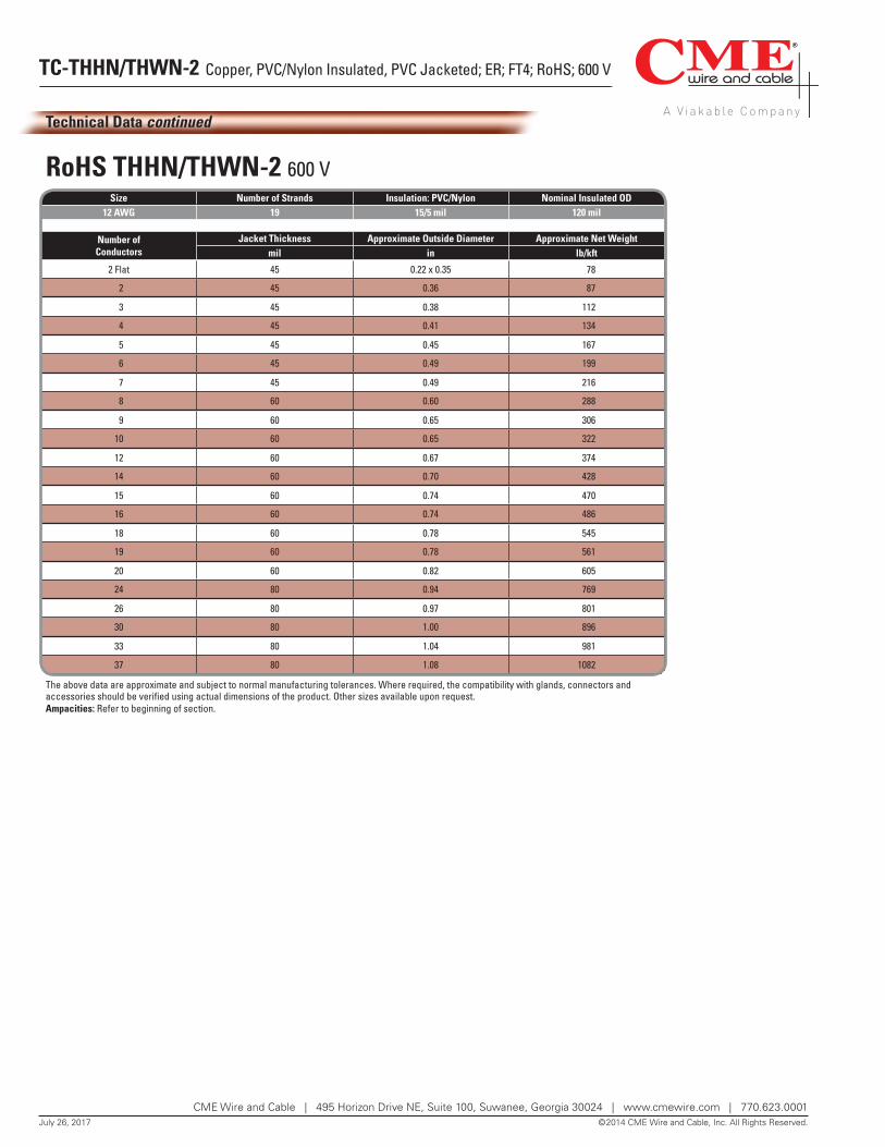
RoHS THHN/THWN-2 600 VSize Number of Strands Insulation: PVC/Nylon Nominal Insulated OD
12 AWG 19 15/5 mil 120 mil
Number of Conductors
Jacket Thickness Approximate Outside Diameter Approximate Net Weightmil in lb/kft
2 Flat 45 0.22 x 0.35 78
2 45 0.36 87
3 45 0.38 112
4 45 0.41 134
5 45 0.45 167
6 45 0.49 199
7 45 0.49 216
8 60 0.60 288
9 60 0.65 306
10 60 0.65 322
12 60 0.67 374
14 60 0.70 428
15 60 0.74 470
16 60 0.74 486
18 60 0.78 545
19 60 0.78 561
20 60 0.82 605
24 80 0.94 769
26 80 0.97 801
30 80 1.00 896
33 80 1.04 981
37 80 1.08 1082
The above data are approximate and subject to normal manufacturing tolerances. Where required, the compatibility with glands, connectors and accessories should be verified using actual dimensions of the product. Other sizes available upon request.Ampacities: Refer to beginning of section.

July 26, 2017 © 2014 CME Wire and Cable, Inc. All Rights Reserved.
CME Wire and Cable | 495 Horizon Drive NE, Suite 100, Suwanee, Georgia 30024 | www.cmewire.com | 770.623.0001
TC-THHN/THWN-2 Copper, PVC/Nylon Insulated, PVC Jacketed; ER; FT4; RoHS; 600 V
Technical Data continued
RoHS THHN/THWN-2 600 VSize Number of Strands Insulation: PVC/Nylon Nominal Insulated OD
10 AWG 19 20/5 mil 154 mil
Number of Conductors
Jacket Thickness Approximate Outside Diameter Approximate Net Weightmil in lb/kft
2 Flat 45 0.26 x 0.42 113
2 45 0.43 128
3 45 0.45 167
4 45 0.49 212
5 60 0.57 270
6 60 0.62 321
7 60 0.62 346
8 60 0.72 434
9 60 0.79 460
10 60 0.79 485
12 60 0.81 567
14 80 0.90 689
15 80 0.94 755
16 80 0.94 780
18 80 0.99 874
19 80 0.99 900
20 80 1.04 971
24 80 1.14 1173
26 80 1.18 1221
30 80 1.22 1374
33 80 1.27 1504
37 80 1.32 1663
The above data are approximate and subject to normal manufacturing tolerances. Where required, the compatibility with glands, connectors and accessories should be verified using actual dimensions of the product. Other sizes available upon request.Ampacities: Refer to beginning of section.
The above data are approximate and subject to normal manufacturing tolerances. Where required, the compatibility with glands, connectors and accessories should be verified using actual dimensions of the product. Other sizes available upon request.Ampacities: Refer to beginning of section.* At the option of manufacturer, Ground Conductor can be divided in three, one in each interstice.
Size AWG or kcmil
Number of
Strands
Insulation Thickness PVC/Nylon
Optional Grounding* Conductor
Jacket Thickness
Approximate Outside
Diameter
Approximate Net Weight
W/O Ground Ground
mil AWG mil in lb/kft lb/kft
Two Conductors8 7 30/6 10 60 0.56 214 251
6 19 30/6 8 60 0.63 299 355
4 19 40/7 8 60 0.77 453 518
2 19 40/7 6 80 0.93 692 791
1 19 50/8 6 80 1.05 867 977
1/0 19 50/8 6 80 1.13 1045 1164
2/0 19 50/8 6 80 1.22 1265 1395
3/0 19 50/8 4 80 1.32 1539 1720
4/0 19 50/8 4 80 1.46 1900 2102
250 37 60/9 4 80 1.57 2214 2432
300 37 60/9 3 110 1.74 2701 2964
350 37 60/9 3 110 1.84 3089 3369
500 37 60/9 2 110 2.09 4232 4599
600 61 80/10 2 110 2.33 5108 5529
750 61 80/10 1 110 2.54 6235 6751

© 2014 CME Wire and Cable, Inc. All Rights Reserved.July 26, 2017
CME Wire and Cable | 495 Horizon Drive NE, Suite 100, Suwanee, Georgia 30024 | www.cmewire.com | 770.623.0001
TC-THHN/THWN-2 Copper, PVC/Nylon Insulated, PVC Jacketed; ER; FT4; RoHS; 600 V
Technical Data continued
RoHS THHN/THWN-2 600 V
Size AWG or kcmil
Number of
Strands
Insulation Thickness PVC/Nylon
Optional Grounding* Conductor
Jacket Thickness
Approximate Outside
Diameter
Approximate Net Weight
W/O Ground Ground
mil AWG mil in lb/kft lb/kft
Three Conductors8 7 30/6 10 60 0.59 279 311
6 19 30/6 8 60 0.67 396 448
4 19 40/7 8 60 0.82 606 660
2 19 40/7 6 80 0.99 929 1011
1 19 50/8 6 80 1.12 1168 1257
1/0 19 50/8 6 80 1.21 1418 1512
2/0 19 50/8 6 80 1.30 1728 1827
3/0 19 50/8 4 80 1.41 2115 2259
4/0 19 50/8 4 80 1.56 2618 2773
250 37 60/9 4 110 1.74 3164 3328
300 37 60/9 3 110 1.85 3712 3912
350 37 60/9 3 110 1.96 4260 4469
500 37 60/9 2 110 2.24 5878 6149
600 61 80/10 2 110 2.50 7093 7393
750 61 80/10 1 110 2.72 8692 9062
Four Conductors8 7 30/6 10 60 0.65 354 387
6 19 30/6 8 60 0.74 508 560
4 19 40/7 8 80 0.95 821 873
2 19 40/7 6 80 1.09 1199 1281
1 19 50/8 6 80 1.23 1508 1590
1/0 19 50/8 6 80 1.33 1836 1922
2/0 19 50/8 6 80 1.44 2243 2334
3/0 19 50/8 4 80 1.56 2752 2886
4/0 19 50/8 4 110 1.79 3521 3663
250 37 60/9 4 110 1.92 4109 4257
300 37 60/9 3 110 2.05 4829 5012
350 37 60/9 3 110 2.17 5551 5740
500 37 60/9 2 110 2.48 7683 7927
600 61 80/10 2 140 2.83 9449 9714
750 61 80/10 1 140 3.08 11573 11901
The above data are approximate and subject to normal manufacturing tolerances. Where required, the compatibility with glands, connectors and accessories should be verified using actual dimensions of the product. Other sizes available upon request.Ampacities: Refer to beginning of section.* At the option of manufacturer, Ground Conductor can be divided in three, one in each interstice.