chevy equinox / gmc terrain 2013-up table of contents · 99-3308g 2 dash disassembly 1. with pocket...
TRANSCRIPT

REV.
1/2
6/20
17
INST
99-3
308G
INSTALLATION INSTRUCTIONS FOR PART 99-3308G
METRA. The World’s best kits.® metraonline.com © COPYRIGHT 2017 METRA ELECTRONICS CORPORATION
CAUTION! All accessories, switches, climate controls panels, and especially air bag indicator lights must be connected before cycling the ignition. Also, do not remove the factory radio with the key in the on position, or while the vehicle is running.
• ISO DIN radio provision with pocket• ISO DDIN radio provision• Painted gray to match factory finish
• A) Radio trim panel • B) Radio brackets • C) Pocket • D) (6) #8 x 3/8” Phillips screws • E) (2) #10 x ¾” Phillips screws • F) (2) #10 panel clips • G) Axxess interface and wiring harness (not shown)
KIT FEATURES
KIT COMPONENTS
WIRING & ANTENNA CONNECTIONS (sold separately)Wiring Harness: • Axxess interface and harness includedAntenna Adapter: • 40-EU55
• Panel removal tool • Phillips screwdriver • 9/32” socket wrench
TOOLS REQUIRED
Chevy Equinox / GMC Terrain 2013-up(with color display)
99-3308G
A
Table of Contents
B C E FD
Dash Disassembly ................................................. 2
Kit Preparation ....................................................... 3
Kit Assembly
– ISO DIN radio provision with pocket ...................... 4– ISO DDIN radio provision ...................................... 4
Axxess Interface Installation .............................5-7

99-3308G
2
Dash Disassembly
1. With pocket above factory radio controls - Remove (2) 9/32” screws from inside the pocket, then unclip and remove the pocket.
2. Without pocket, just unsnap and remove the panel. (Figure A)
3. Unsnap, unplug, and remove the radio/ climate control panel. (Figure B)
4. Unclip and remove the (2) side panels from the left and right side of the pocket/CD slot panel. (Figure C)
5. Remove (4) 9/32” screws to remove the pocket/CD slot panel. Remove the power outlet and attach it to the included pocket if installing single DIN. If you are mounting a DDIN the power outlet will not be retained with this kit. Remove the rubber bottom from the factory pocket and save it for final assembly. (Figure D)
6. Remove (2) 9/32” screws from each a/c vent then unclip and remove the vents. Remove the screws inside and under the vent cavities and two from below the vent locations. (this will allow flex in the dash to fit the aftermarket in later). (Figure E)
7. Remove (4) 9/32” screws securing the radio chassis and remove. (Figure F)
Continue to Kit Preparation
(Figure A) (Figure D)
(Figure C) (Figure F)
(Figure B) (Figure E)
99-3308G
(Figure A) (Figure B)
3
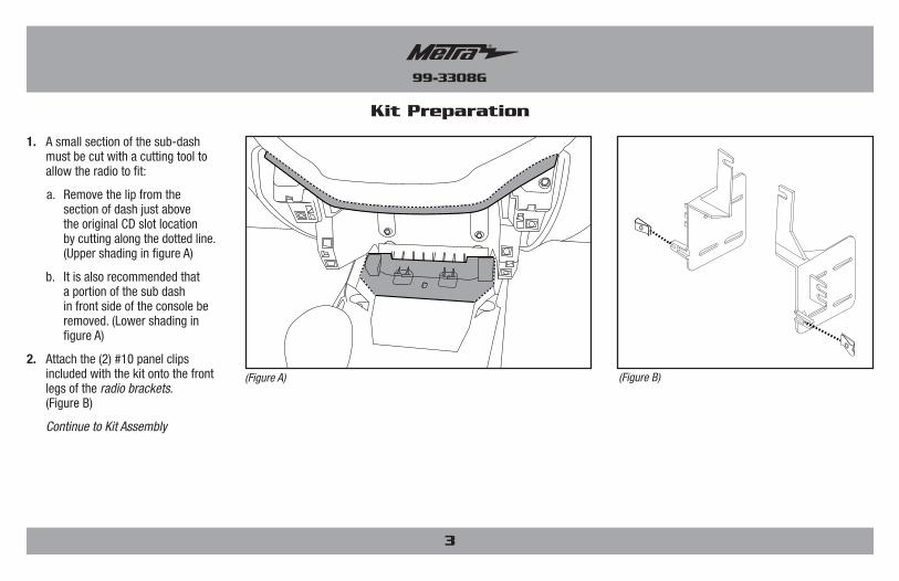
Kit Preparation
1. A small section of the sub-dash must be cut with a cutting tool to allow the radio to fit:
a. Remove the lip from the section of dash just above the original CD slot location by cutting along the dotted line. (Upper shading in figure A)
b. It is also recommended that a portion of the sub dash in front side of the console be removed. (Lower shading in figure A)
2. Attach the (2) #10 panel clips included with the kit onto the front legs of the radio brackets. (Figure B)
Continue to Kit Assembly

99-3308G
4
Kit Assembly
ISO DDIN radio provision
1. Attach the radio brackets to the radio using the screws supplied with the radio. (Figure A)
Continue to Axxess Interface Installation
(Figure B)
(Figure A)
ISO DIN radio provision with pocket
1. Attach the pocket to the radio brackets using the (4) #8 x 3/8” Phillips screws provided. (Figure A)
2. Remove the metal DIN sleeve and trim ring from the aftermarket radio.
3. Slide the radio into the bracket/pocket assembly and then secure it using the screws supplied with the radio. (Figure B)
Continue to Axxess Interface Installation
(Figure A)
99-3308G
5
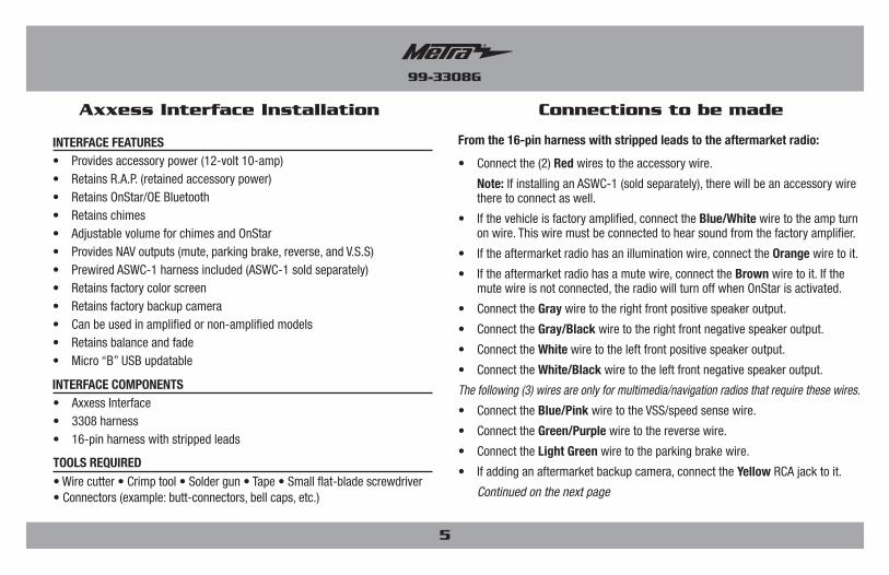
Axxess Interface Installation
• Provides accessory power (12-volt 10-amp)• Retains R.A.P. (retained accessory power)• Retains OnStar/OE Bluetooth• Retains chimes• Adjustable volume for chimes and OnStar• Provides NAV outputs (mute, parking brake, reverse, and V.S.S)• Prewired ASWC-1 harness included (ASWC-1 sold separately)• Retains factory color screen• Retains factory backup camera• Can be used in amplified or non-amplified models• Retains balance and fade• Micro “B” USB updatable
INTERFACE FEATURES
• Wire cutter • Crimp tool • Solder gun • Tape • Small flat-blade screwdriver • Connectors (example: butt-connectors, bell caps, etc.)
TOOLS REQUIRED
• Axxess Interface• 3308 harness• 16-pin harness with stripped leads
INTERFACE COMPONENTS
From the 16-pin harness with stripped leads to the aftermarket radio:
• Connect the (2) Red wires to the accessory wire.
Note: If installing an ASWC-1 (sold separately), there will be an accessory wire there to connect as well.
• If the vehicle is factory amplified, connect the Blue/White wire to the amp turn on wire. This wire must be connected to hear sound from the factory amplifier.
• If the aftermarket radio has an illumination wire, connect the Orange wire to it.
• If the aftermarket radio has a mute wire, connect the Brown wire to it. If the mute wire is not connected, the radio will turn off when OnStar is activated.
• Connect the Gray wire to the right front positive speaker output.
• Connect the Gray/Black wire to the right front negative speaker output.
• Connect the White wire to the left front positive speaker output.
• Connect the White/Black wire to the left front negative speaker output.
The following (3) wires are only for multimedia/navigation radios that require these wires.
• Connect the Blue/Pink wire to the VSS/speed sense wire.
• Connect the Green/Purple wire to the reverse wire.
• Connect the Light Green wire to the parking brake wire.
• If adding an aftermarket backup camera, connect the Yellow RCA jack to it.
Continued on the next page
Connections to be made

99-3308G
6
From the 3308 harness to the aftermarket radio:• Connect the Black wire to the ground wire.• Connect the Yellow wire to the battery wire.• Connect the Green wire to the left rear positive speaker output.• Connect the Green/Black wire to the left rear negative speaker output.• Connect the Purple wire to the right rear positive speaker output.• Connect the Purple/Black wire to the right rear negative speaker output.• If retaining the factory AUX-IN jack, connect the Red & White RCA jacks
to the AUX input. Note: a. The AUX-IN jack can only be used if it is a single AUX-IN jack. b. If the AUX-IN jack has a USB port, neither can be used.12-pin pre-wired ASWC-1 harness:• This harness is to be used along with the optional ASWC-1 (not included) to
retain steering wheel audio controls. If the ASWC-1 is not being used, disregard this harness. If it will be used, please refer to the ASWC-1 instructions for radio connections and programming.
Note: Disregard the harness that comes with the ASWC-1.• Connect the Red wire to the accessory wire. Note: The relay attached to the 3308 harness is only for audible turn signal
clicks. No extra steps are required to retain this, so leave it as-is. Continue to Final Assembly
With the key in the off position:1. Connect the 16-pin harness with stripped leads, and the 3308 harness,
into the interface.
2. Connect the 3308 harness to the vehicle.
Note: Make sure to connect the factory LDVS harness (blue connector) that was disconnected from factory radio, into the interface.
3. Locate the factory antenna connector in the dash and complete all necessary connections to the radio. Metra recommends using the proper mating adapter from Metra.
4. Before using the kit it must be initialized.
Attention! If the interface loses power for any reason, the following steps will need to be performed again. Also, if installing an ASWC-1 connect it after you initialize and test the interface/radio, with the key in the off position.
a. Turn the key (or push-to-start button) to the ignition position and wait until the radio comes on.
Note: If the radio does not come on within 60 seconds, turn the key to the off position, disconnect the interface, check all connections, reconnect the interface, and then try again.
b. Turn the key to the off position, and then to the accessory position. Test all functions of the installation for proper operation, before reassembling the dash
5. Test the radio and climate controls for proper operation.
Continued on the next page
Connections to be made (cont.) Final Assembly

99-3308G
7
Final Assembly (cont.) Backup Camera Settings
6. Chime level adjustment:
a. With the vehicle on, turn it off and leave the keys in the ignition. Open the driver’s door; chimes will be heard.
b. Wait 10 seconds, and then with a small flat-blade screwdriver, turn the potentiometer clockwise to raise the chime level; counterclockwise to lower the chime level.
c. When the chime is at a desired level, remove the keys from the ignition. This will lock the chime volume at its current level.
7. Secure the completed assembly into the dash using the factory screws.
8. Attach the radio trim panel over the completed assembly, and then reassemble the dash in reverse order of disassembly.
From the main OEM screen:
1. Press the gear icon located in the bottom right corner to enter the settings menu.
3. Press the “Backup Camera Settings” button to enter the backup camera settings menu.
4. If you are using the factory equipped backup camera, select “OEM Backup Camera”.
• If you are using an aftermarket backup camera, select “Aftermarket Backup Camera”
• If there is no backup camera present, keep selected “No Backup Camera”
Note: If there is no backup camera present and this setting is not changed, the OEM screen will switch to a black screen while the vehicle is in reverse.
2. Press the “Customize” button to enter the customize menu.

REV.
1/2
6/20
17
INST
99-3
308G
INSTALLATION INSTRUCTIONS FOR PART 99-3308G
KNOWLEDGE IS POWEREnhance your installation and fabrication skills by enrolling in the most recognized and respected mobile electronics school in our industry.Log onto www.installerinstitute.com or call 800-354-6782 for more information and take steps toward a better tomorrow.
Metra recommends MECP certified technicians
IMPORTANTIf you are having difficulties with the installation of this product, please call our Tech Support line at 1-800-253-TECH. Before doing so, look over the instructions a second time, and make sure the installation was performed exactly as the instructions are stated. Please have the vehicle apart and ready to perform troubleshooting steps before calling.
METRA. The World’s best kits.® metraonline.com © COPYRIGHT 2017 METRA ELECTRONICS CORPORATION
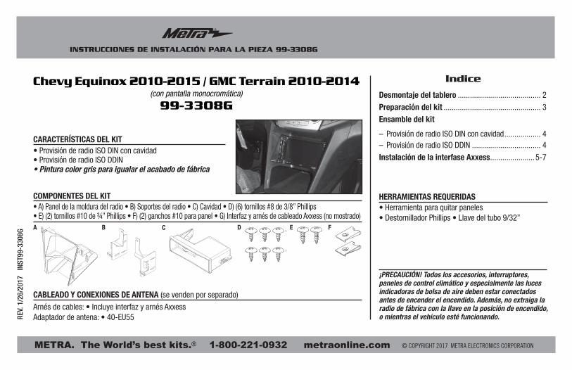
INSTRUCCIONES DE INSTALACIÓN PARA LA PIEZA 99-3308G
METRA. The World’s best kits.® metraonline.com1-800-221-0932 © COPYRIGHT 2017 METRA ELECTRONICS CORPORATION
REV.
1/2
6/20
17
INST
99-3
308G
¡PRECAUCIÓN! Todos los accesorios, interruptores, paneles de control climático y especialmente las luces indicadoras de bolsa de aire deben estar conectados antes de encender el encendido. Además, no extraiga la radio de fábrica con la llave en la posición de encendido, o mientras el vehículo esté funcionando.
Indice
• Herramienta para quitar paneles • Destornillador Phillips • Llave del tubo 9/32”
HERRAMIENTAS REQUERIDAS
• Provisión de radio ISO DIN con cavidad• Provisión de radio ISO DDIN• Pintura color gris para igualar el acabado de fábrica
• A) Panel de la moldura del radio • B) Soportes del radio • C) Cavidad • D) (6) tornillos #8 de 3/8” Phillips • E) (2) tornillos #10 de ¾” Phillips • F) (2) ganchos #10 para panel • G) Interfaz y arnés de cableado Axxess (no mostrado)
CARACTERÍSTICAS DEL KIT
COMPONENTES DEL KIT
CABLEADO Y CONEXIONES DE ANTENA (se venden por separado)
Arnés de cables: • Incluye interfaz y arnés AxxessAdaptador de antena: • 40-EU55
Chevy Equinox 2010-2015 / GMC Terrain 2010-2014(con pantalla monocromática)
99-3308G
A B C E FD
Desmontaje del tablero ......................................... 2
Preparación del kit ................................................ 3
Ensamble del kit
– Provisión de radio ISO DIN con cavidad .................. 4– Provisión de radio ISO DDIN .................................. 4
Instalación de la interfase Axxess ......................5-7

99-3308G
Desmontaje del tablero
2
1. Con la cavidad por encima de los controles del radio de fábrica, retire los (2) tornillos de 9/32” de dentro de la cavidad, luego desenganche y quite la cavidad.
2. Sin la cavidad, solo suelte a presión y quite el panel. (Figura A)
3. Suelte a presión, desconecte y quite todo el panel del radio/control del clima. (Figura B)
4. Desenganche y quite los (2) paneles del lado izquierdo y derecho del panel de la cavidad/ranura del CD. (Figura C)
5. Quite los (4) tornillos de 9/32” para quitar el panel de la cavidad/ranura del CD. Quite la toma de corriente y fíjela a la cavidad incluida si está instalando un solo DIN. Si va a montar un DDIN, la toma de corriente no se retendrá en este equipo. Quite el botón de hule de la cavidad de fábrica y consérvelo para el ensamblado final. (Figura D)
6. Quite los (2) tornillos de 9/32” de cada rejilla de aire acondicionado y luego desenganche y quite las rejillas. Quite los tornillos de dentro y debajo de las cavidades de las rejillas y dos de debajo de las ubicaciones de las rejillas. (Esto permitirá flexibilidad en el tablero para que quepa después el mercado secundario). (Figura E)
7. Quite los (4) tornillos de 9/32” que sujetan el chasis del radio para retirarlo. (Figura F)
Continúe con la preparación del kit
(Figura A) (Figura D)
(Figura C) (Figura F)
(Figura B) (Figura E)
99-3308G
3
(Figura A) (Figura B)
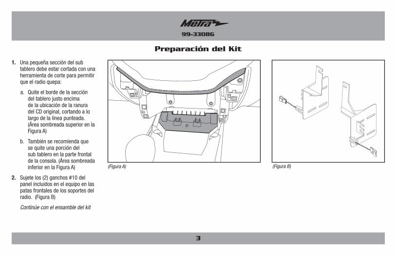
Preparación del Kit
1. Una pequeña sección del sub tablero debe estar cortada con una herramienta de corte para permitir que el radio quepa:
a. Quite el borde de la sección del tablero justo encima de la ubicación de la ranura del CD original, cortando a lo largo de la línea punteada. (Área sombreada superior en la Figura A)
b. También se recomienda que se quite una porción del sub tablero en la parte frontal de la consola. (Área sombreada inferior en la Figura A)
2. Sujete los (2) ganchos #10 del panel incluidos en el equipo en las patas frontales de los soportes del radio. (Figura B)
Continúe con el ensamble del kit

99-3308G
Ensamble del kit
4
Provisión de radio ISO DDIN
1. Sujete los soportes del radio al radio usando los tornillos que se suministraron con el radio. (Figura A)
Continúe con Instalación de la interfase Axxess
(Figura B)
(Figura A)
Provisión de radio ISO DIN con cavidad
1. Sujete la cavidad a los soportes del radio con los (4) tornillos Phillips #8 de 3/8” suministrados. (Figura A)
2. Quite la manga de metal DIN y el anillo de moldura del radio de mercado secundario
3. Deslice el radio hacia adentro del ensamble completo y sujételo usando los tornillos suministrados con el radio. (Figura B)
Continúe con Instalación de la interfase Axxess
(Figura A)

99-3308G
5
Instalación de la interfase Axxess
• Provee corriente de accesorios (12 voltios 10 amperes)• Retiene R.A.P. (corriente de accesorio retenida)• Retiene OnStar/Bluetooth de fabricante original• Retiene los tonos• Volumen ajustable para tonos y OnStar• Proporciona salidas de NAV (silencio, freno de mano, reversa y V.S.S.)• Arnés ASWC-1 precableado incluido (el ASWC-1 se vende por separado)• Retiene la pantalla de color de fábrica• Retiene la cámara de reversa de fábrica• Se puede usar en modelos amplificados o en modelos no amplificados• Retiene el balance y la intensidad• Actualizable a micro “B” USB
CARACTERÍSTICAS DE LA INTERFAZ
• Cortador de cables • Pelacables • Pistola soldadora • Cinta • Conectores (ejemplo: conectores de extremo, de campana, etc). • Destornillador plano pequeño
HERRAMIENTAS REQUERIDAS
• Interfaz Axxess• Arnés 3308• Arnés de 16 pins con conectores pelados
COMPONENTES DE LA INTERFASE
Conexiones que se deben hacer
Del arnés de 16 pins con conectores pelados al radio de mercado secundario:
• Conecte los (2) cables rojos al cable de accesorios.
Nota: si va a instalar un ASWC-1 (se vende por separado), habrá un cable de accesorio que también debe conectar.
• Si el vehículo está amplificado de fábrica, conecte el cable azul/blanco al cable de encendido del amplificador. Este cable debe estar conectado para escuchar sonido del amplificador de fábrica.
• Si el radio de mercado secundario tiene cable de silencio, conecte a él el cable anaranjado.
• Si el radio de mercado secundario tiene cable de silencio, conecte a él el cable marrón. Si el cable de silencio no está conectado, el radio se apagará cuando se active OnStar.
• Conecte el cable gris con la salida positiva de la bocina derecha del frente.
• Conecte el cable gris/negro con la salida negativa de la bocina derecha del frente.
• Conecte el cable blanco a la salida positiva de la bocina izquierda delantera.
• Conecte el cable blanco/negro a la salida negativa de la bocina izquierda delantera.
Los siguientes (3) cables son únicamente para radios con multimedios/navegación que requieren estos cables.
• Conecte el cable azul/rosado al cable VSS/de detección de velocidad.
• Conecte el cable verde/púrpura al cable de reversa.
• Conecte el cable verde claro al cable de freno de mano.
• Si agrega una cámara de reversa de mercado secundario, conéctele el conector RCA amarillo.
Continúa en la siguiente página
99-3308G
Conexiones que se deben hacer (cont.) Ensamble final
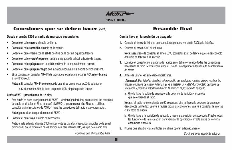
Con la llave en la posición de apagado:
1. Conecte el arnés de 16 pins con conectores pelados y el arnés 3308 a la interfaz.
2. Conecte el arnés 3308 al vehículo.
Nota: asegúrese de conectar el arnés LDVS (conector azul) de fábrica que se desconectó del radio de fábrica, a la interfaz.
3. Localice el conector de la antena de fábrica en el tablero y realice todas las conexiones necesarias al radio. Metra recomienda el uso de un adaptador adecuado de acoplamiento de Metra.
4. Antes de usar el kit, este debe inicializarse.
¡Atención! Si la interfaz pierde la alimentación por cualquier motivo, deberá realizar los siguientes pasos de nuevo. Además, si va a instalar un ASWC-1, conéctelo después de inicializar y probar la interfaz/radio con la llave en la posición de apagado.
a. Gire la llave (o botón de arranque) a la posición de ignición y espere a que se encienda el radio.
Nota: si el radio no se enciende en 60 segundos, gire la llave a la posición de apagado, desconecte la interfaz, vuelva a revisar todas las conexiones, vuelva a conectar la interfaz e inténtelo de nuevo.
b. Gire la llave a la posición de apagado y luego a la posición de accesorio. Pruebe todas las funciones de la instalación para verificar la operación correcta antes de volver a ensamblar el tablero
5. Pruebe que el radio y los controles del clima operen adecuadamente.
Continúa en la siguiente página
Desde el arnés 3308 al radio de mercado secundario:
• Conecte el cable negro al cable de tierra.
• Conecte el cable amarillo al cable de la batería.
• Conecte el cable verde con la salida positiva de la bocina izquierda trasera.
• Conecte el cable verde/negro con la salida negativa de la bocina izquierda trasera.
• Conecte el cable púrpura con la salida positiva de la bocina derecha trasera.
• Conecte el cable púrpura/negro con la salida negativa de la bocina derecha trasera.
• Si se conserva el conector AUX-IN de fábrica, conecte los conectores RCA rojo y blanco a la entrada AUX.
Nota: a. El conector AUX-IN solo se puede usar si es un conector AUX-IN autónomo.
b. Si el conector AUX-IN tiene un puerto USB, ninguno puede usarse.
Arnés ASWC-1 precableado de 12 pins:• Este arnés se debe usar junto con el ASWC-1 opcional (no incluido) para retener los controles
de audio en el volante. Si no se usará el ASWC-1, ignore este arnés. Si se va a utilizar, consulte las instrucciones de ASWC-1 para las conexiones del radio y la programación.
Nota: ignore el arnés que viene con el ASWC-1.
• Conecte el cable rojo al cable de accesorios.
Nota: el relé adjunto al arnés 3308 únicamente es para los chasquidos audibles de la señal direccional. No se requieren pasos adicionales para retener esto, así que deje como está.
Continúe con el ensamble final
6
99-3308G
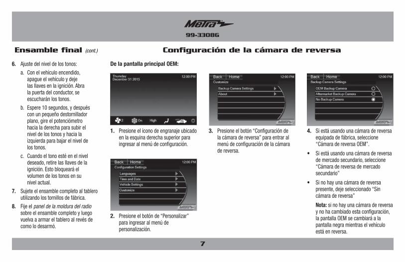
Ensamble final (cont.)
7
6. Ajuste del nivel de los tonos:
a. Con el vehículo encendido, apague el vehículo y deje las llaves en la ignición. Abra la puerta del conductor, se escucharán los tonos.
b. Espere 10 segundos, y después con un pequeño destornillador plano, gire el potenciómetro hacia la derecha para subir el nivel de los tonos y hacia la izquierda para bajar el nivel de los tonos.
c. Cuando el tono esté en el nivel deseado, retire las llaves de la ignición. Esto bloqueará el volumen de los tonos en su nivel actual.
7. Sujete el ensamble completo al tablero utilizando los tornillos de fábrica.
8. Fije el panel de la moldura del radio sobre el ensamble completo y luego vuelva a armar el tablero al revés de como lo desarmó.
Configuración de la cámara de reversa
De la pantalla principal OEM:
1. Presione el ícono de engranaje ubicado en la esquina derecha superior para ingresar al menú de configuración.
3. Presione el botón “Configuración de la cámara de reversa” para entrar al menú de configuración de la cámara de reversa.
4. Si está usando una cámara de reversa equipada de fábrica, seleccione “Cámara de reversa OEM”.
• Si está usando una cámara de reversa de mercado secundario, seleccione “Cámara de reversa de mercado secundario”
• Si no hay una cámara de reversa presente, deje seleccionado “Sin cámara de reversa”
Nota: si no hay una cámara de reversa y no ha cambiado esta configuración, la pantalla OEM se cambiará a la pantalla negra mientras el vehículo está en reversa.
2. Presione el botón de “Personalizar” para ingresar al menú de personalización.

INSTRUCCIONES DE INSTALACIÓN PARA LA PIEZA 99-3308G
METRA. The World’s best kits.® metraonline.com1-800-221-0932 © COPYRIGHT 2017 METRA ELECTRONICS CORPORATION
REV.
1/2
6/20
17
INST
99-3
308G
KNOWLEDGE IS POWEREnhance your installation and fabrication skills by enrolling in the most recognized and respected mobile electronics school in our industry.Log onto www.installerinstitute.com or call 800-354-6782 for more information and take steps toward a better tomorrow.
Metra recomienda técnicos con certificación del Programa de Certificación en Electrónica Móvil (Mobile Electronics Certification Program, MECP).
EL CONOCIMIENTO ES PODERMejore sus habilidades de instalación y fabricación inscribiéndose en la escuela de dispositivos electrónicos móviles más reconocida y respetada de nuestra industria. Regístrese en www.installerinstitute.com o llame al 800-354-6782 para obtener más información y avance hacia un futuro mejor.
IMPORTANTESi tiene dificultades con la instalación de este producto, llame a nuestra línea de soporte técnico al 1-800-253-TECH. Antes de hacerlo, revise las instrucciones por segunda vez y asegúrese de que la instalación se haya realizado exactamente como se indica en las instrucciones. Por favor tenga el vehículo desarmado y listo para ejecutar los pasos de resolución de problemas antes de llamar.