chen, s.c
TRANSCRIPT

PFC/JA-89-45
Growth and Frequency Pushing Effects
in Magnetron Phase-Locking
Chen, S.C.
Plasma Fusion Center
Massachusetts Institute of Technology
Cambridge, MA 02139
October 1989
This work was supported by Harry Diamond Labs (Army) Contract DAALO2-89-K-0084

Growth and Frequency Pushing Effects in Magnetron Phase-Locking
S.C. Chen
Plasma Fusion Center
Massachusetts Institute of Technology, Cambridge, MA 02139
ABSTRACT
A magnetron-specific equivalent-circuit model has been developed which takes into
account the unconventional magnetron growth characteristics as well as the frequency
pushing effect. These effects, which owe their origin to the highly nonlinear electron-wave
interaction, are shown to play important roles in the magnetron phase locking process.
The model predicts a wider locking-bandwidth and a shorter locking time than those in
conventional locking theory. The phase-locked amplitude resonance occurs, as the results
indicated, at an injection frequency different from that of the free-running oscillator.
1
I Introduction
The past ten years have seen the rapid progress made in the research on high power
microwaves. 1-3 Phase control of high power oscillators appears to be the logical and the
promising means for harnessing and enhancing the unprecedented power output.4-6 The
relativistic magnetron, with its reentrant nature and high efficiency, is an especially desir-
able candidate as the heart of a phase-locked system.7- 9 Research in this area has been
very active and major results were achieved recently in a short-pulse experiment. 0 Long-
pulse operation"1 4 and the subsequent phase-locking" of relativistic magnetrons,
provide more interesting application possibilities and involve greater technical challenges
not encountered in the short-pulse experiments.
Frequency pushing effect, which has been observed experimentally in relativistic mag-
netrons recently,' 6 was identified and proved to be of critical importance in obtaining
phase control. 17,"
8 On the other hand, phase locking of pulsed oscillators - especially
those with a cavity fill time comparable with (or not much longer than) the pulse length
- requires attention to the details of the magnetron growth process. The ubiquitous
van der Pol equation' 9 lacks both the magnetron-specific growth and frequency pushing
effects; hence will not serve the purpose of a magnetron model equation. However, the
highly nonlinear crossed-field interaction in magnetrons involves very complex geometry
and particle dynamics, hence the grow-frequency characteristics (or, equivalently, the dis-
persion relation) cannot be calculated easily from first principles. It is the purpose of
this paper to temporarily de-emphasize the differences between the relativistic and the
conventional magnetrons, and to apply the conceptually simple approach - modelling
the growth/frequency features within the lumped-circuit model - to obtain fundamental
understanding of the phase-locking behavior in magnetrons.
Section II discusses the operating features of magnetrons and justifies the choice of
model equations for the electronic conductance and susceptance using two independent
simulation techniques. An equivalent circuit model based on the model equations is con-
structed, followed by an analysis of the free-running oscillator state. In section III, phase
2

locking with weak injection near the oscillator frequency is analyzed. Important effects
due to the magnetron-specific features are identified.
3

II. Signal growth and frequency-pushing in magnetrons
One distinct feature that sets magnetrons apart from other oscillators is the growth
and saturation characteristics. This is illustrated qualitatively in Figure 1, in which the
electronic conductance 9 (the ratio of RF current and RF voltage) is plotted against the RF
voltage. The conductance curve for magnetrons (Figure la) assumes a "concave" shape
with a second derivative greater than zero. This phenomenon, namely the existence of
finite RF current even with very small RF voltage, has long been observed in magnetron
operation. 20 ,21 The state of zero current is extremely unstable which, with very small
perturbation, breaks into a state of large current. This behavior, which differs drastically
from that of most conventional self-excited oscillators (Figure 1b), leads to some unique
properties in magnetrons to be described in the following.
To model this magnetron feature, Slater 20 ,21 suggested using
1 VD Cg-1) (1)R V
to relate the conductance to the rms RF-voltage (see Figure la). This is to be compared
with the more conventional expression for other oscillators (Figure 1b)
V2
9=go(1~ 2) (2)V 2VDC
(where go is the small-signal gain) which can often be derived from first principles.19
In addition to the in-phase component of the RF current which governs the temporal
growth, of equal importance is the contribution from the out-of-phase RF current which
determines the output frequency. Frequency-pushing, namely the frequency change caused
by the presence of the electron space charge - the same space charge responsible for the
gain -, is modeled by the following expression 20 ,21
b = bo - g - tana. (3).
The relationship between the real and imaginary parts of the frequency (susceptance b and
conductance g) is evident from Figure 1. It should not be surprising that the frequency
4
pushing effect, represented by the pushing parameter a of order unity, plays a major role
in magnetron phase locking since the angle a characterizes the phase lag between the
electron bunch and the resonant wave. In simple devices like reflex klystrons, the angle
a is found to be the deviation of the average transit-time from 2pr (for 1-mode) in the
repeller region.2 1 It is believed the angle a in magnetrons is directly related to the angle
between the rotating electron spoke and the RF voltage peak.
To justify the choice of the model equation (1), we have22 extended an existing semi-
empirical model of conventional magnetrons 23- 27 and applied the model to examine
the behavior of the electronic conductance. The important variable in this theory is a,
the relative phase angle between the rotating space charge spoke and the RF-peak. By
assuming the existence of spokes with shapes suggested by particle simulations 28 ,29 , and
with a charge density distribution given by the Brillouin model"0 , the electron currents are
calculated under synchronism conditions. Each spoke is treated as one macroparticle with
assigned charge and calculated average velocity components. The RF field in the cavity
is calculated from the energy conservation equation, which involves modeling the particle
loss mechanisms in the anode and cathode as well as the RF loss due to the finite cavity
Q. With the system of equations, it is possible to find the operating point self-consistently,
and to predict the saturated power level and the output frequency. Such a model scales
correctly over a wide range of known magnetron designs. 23
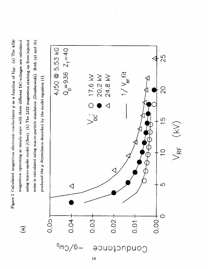
We have developed a computer program based on this model and applied it to the
4J50 magnetron (high power X-band, see Vaughan2 3 for tube parameters). By changing
the loading level at the output, the corresponding operating RF-amplitudes under steady-
state condition were monitored. The result is shown in Figure 2a. We have22 successfully
reproduced the gain characteristics ( Figure 2a) described by Eq.(1).
A second approach was taken by Dombrowsky3 1 using a more elaborate simulation
scheme.3 2 The result of the simulation is shown in Figure 2b.
The spoke model 22 and the Dombrowski simulation3 1 thus provide independent means
of confirming the 1/V1.pF dependence of the magnetron growth.
5

Based on the magnetron-specific models for g and b described in equations (1) and
(3), we then proceed to construct an equivalent-circuit model and study the steady-state
and the phase-locking operation in magnetrons.
The model is based upon the general oscillator equation derived from the standard
parallel RLC circuit (see Figure 3). The magnetron gain mechanism is repr-esented by a
shunt electronic admittance g + ib. The single-mode oscillator equation for this circuit is
g-+ib W wo 1 G-+ iB= -( )+ + , (4)
CWO WO W Qo Qe!t
where G + iB is the voltage-dependant nonlinear complex admittance of the load. In the
equation, w is the output frequency, wo = , Qo = RCwo, and Q..t is the external Q.
Inserting (1) and (3) into (4), and separating the real and imaginary parts, the steady-
state values of the amplitude VRFO and frequency w' for a free running magnetron are found
to beVDC 1
'RFO 2RC lwo( ±R O) (5),
and1 bo Bwo wo - tana= C Qezt 2 QL
Equation (6) contains both the frequency pulling (B) ) as well as the pushing 2"QLtn
terms. We define a growth parameter
1 1 1(7y= -wo( + )(7)
2 QL RCwo
for later convenience. The amplitude and frequency evolution in magnetron start-up phase
can be calculated under situations when the frequency is much greater than the growth
rate w > -y, hence the growth process can be approximated adiabatically by a succession
of instantaneous steady-state solutions. The oscillator equation is then modified by the
addition of a temporal growth rate -ir(t) to the frequency w
g+ib . w -iF wo 1 G+iBCOO WOo -Li; Qo Qezt
where
P(t) = (9)VBF
6
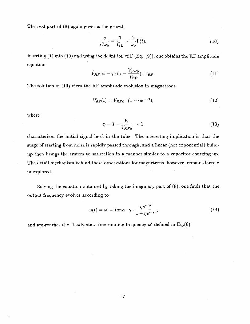
The real part of (8) again governs the growth
g 1 2S- -(t). (10)
CWo QL wO
Inserting (1) into (10) and using the definition of f (Eq. (9)), one obtains the RF amplitude
equation
VRFO)"R F S 7-( R. (1
VRF
The solution of (10) gives the RF amplitude evolution in magnetrons
VRF(t) VRFO - (1 - e(12)
where
1 - ~ 1 (13)VRF
characterizes the initial signal level in the tube. The interesting implication is that the
stage of starting from noise is rapidly passed through, and a linear (not exponential) build-
up then brings the system to saturation in a manner similar to a capacitor charging up.
The detail mechanism behind these observations for magnetrons, however, remains largely
unexplored.
Solving the equation obtained by taking the imaginary part of (8), one finds that the
output frequency evolves according to
w(t) = w' - tana 1 (14)
and approaches the steady-state free running frequency w' defined in Eq.(6).
7

III. Phase locking of magnetrons
We follow the techniques developed in previous work 20 ,2 1 ,3 3 ,3 4 and treat the locking
source as part of the magnetron load which injects counter propagating I, and Vi at a
frequency wi. The total admittance, including the locking source, at the load for the driven
magnetron is
Ie''o + Ieiw'i I 1 + ife"'i(WIw)t
Vei '' + V ies"' V 1 + -yei(w 1-w )t ( )
- [1 + (El - Ev)e' 'Iw)t + (,2 - EVEI)e2i2,i-,)t + O(C3)],
where
eV 1 '1 (16)V I
Consider the case of injection locking with a weak reference signal and neglect the
O(E2,) terms in (15), the admittance simplifies to
Y (t) ~ (G + iB) - (1 + (ci - ev)ei(wi'W)t), (17)
where G + iB is the matched load admittance as in Figure 3. It is convenient to define the
injection parameter p , the injection phase 9i, and the relative phase 0 as follows:
1 -p = 2(,E - ev) - v/G2 + B 2 (18)2
Oi = sin1 B (19)v/2+ B2
0(t) = q-Ma(t) - (wit + 9i). (20)
Introducing the total load admittance (17) into the oscillator equation (4)
g +ib w wo 1 G + iB + 2pe-i[-('t+Oi)]S (- -) + +Q, (21)
cWO WO W Q0 Qezt
and separating the real and imaginary parts, we have
g 1 2pcos9 (22)cWO Q Qemc
b 2(w - WO) B 2psinB (23)cWO Q.t Qext
8

In deriving (23), we have assumed w ~ wo for simplicity. This formulation is valid for
oscillators in general, since the form of g and b has not been specified yet.
It is interesting to point out that although the magnetron-specific features (1) and (3)
were repetitively described and emphasized in Slater's work20 '2 1, they were not included
in his phase locking calculations. 20 Here we introduce Eqs. (1) and (3) into Eqs. (22)
and (23) , and obtain the equations for driven magnetrons. The equations governing the
amplitude and the frequency evolution are
1VRF (t) = VRFO pwoco4(t))
1+ QewtY
and
w(t) - W' = 0) (sinB(t) - cosD(t) . tana). (25)
To simplify the equations, we normalize all frequencies with respect to wo and introduce
the dimensionless injection and detuning parameters into (24) and (25)
y = , - . (26)Qex' LOO
The resultant equations
1VIRF = VRF(O(t)) = VRFO (27)
(1 + Cos 0(t))
and
dt sin(9 - a) + a (28)dt |Cosa |
describe the amplitude and the relative phase evolution. It is important to realize the
parameter range in which the analysis is valid. The assumptions we have made so far can
be conveniently collected in terms of a simple inequality which relates frequency, growth
parameter, injection amplitude, pushing parameter, and frequency difference:
1= WO > -y > P >1 0- . (29)1 cosa I
The condition under which phase locking occurs is obtained by setting (28) to zero
for steady-state,
> -, (30)cosal
9

which reduces to the familiar Adler's condition3 5 p ;> o when the frequency pushing
parameter a is zero. The widening of the locking frequency range can be quite appreciable
depending on the amount of frequency pushing. The experimentally observed magnitude
of a ranges roughly from 0 to 1.5 depending on the operating DC voltage. Under normal
operating condition, it is on the low side. An a of 0.25 is chosen as the typical value and is
used in the following analysis. The final relative phase of the locked system is also modified
by the nonzero pushing parameter a
Oc = Sin-1(-- 0 1 CosaI) +a. (31)Y
To summarize the steady-state behavior of the weak injection phase locking system
near the fundamental locking zone, we combine the phase and amplitude equations (27)
and (28) by cancelling the O-dependance. The resultant equation
( -1)2 To0R 1)2 - (f)2 cosa + - sina)2 (32)
contains the dependance of output amplitude VRF on three parameters: the injection
parameter p' = p/1 cosa | , the pushing parameter a, and the detuning parameter a. The
effect of the frequency pushing can be singled out by comparing the above equation with
the case when a = 0VRO-1)2 .2
Figure 4 illustrates this comparison by showing the loci of the steady phase-locked states
on the e-VRp plane for -y = .1. Different curves correspond to different values of injection
amplitudes it. Figure 4 depicts the dependance of VR on a for the case of (a) no frequency
pushing (a = 0), and (b) finite frequency pushing (a = 0.25). The free-running state is
represented by the point o = 0, Vp.F/VRFO = 1. It is clearly seen in Figure 4a, that
the loci of the phase locked states for weak injection form a family of "ellipses" with
an eccentricity e = V1 - -y2. The deviation of the "ellipses" from exact elliptical shape
is caused by the unconventional form of the growth model (1); the results obtained for
conventional oscillators based on (2) form evenly spaced ellipses with a common geometric
10

center. Characterized by an injection parameter ji, each ellipse in Figure 4 consists of
two branches. The result of a stability analysis established the existence of a stability
criteria (cos 0 1,k < 0), shown in Figure 4 as the dashed line. Only the upper branch of
the double-valued ellipses constitutes the stable solutions.
A nonzero a causes the ellipses to rotate around the origin (Figure 4b) . In phase-
locked states, the frequency pushing effectively rotates the ellipses by an angle
01 = tan-'(-y sina), (34)
which results in a wider locking bandwidth, as described by (30), than the conventional
Adler's condition. The maximum power output, that is, the amplitude resonance, occurs
at an injection frequency detuned from the free-running value
n = [I sina. (35)
The amount of detuning, namely the difference of the optimal injection frequency and the
free-running frequency, can become appreciable with large p. For example, the detuning
can be 1% for a p of 0.4.
The boundary between the stable and the unstable branches, shown in Figure 4 as
the dashed line, is also tilted by an angle
_ _ _sin2a 1 sin2a02 = tan - tan- . (36)
2-y(1 - (11111)2) 27
The tilting effectively makes the phase-locked power output asymmetrical with respect to
the injection frequency.
Transient behavior is of special interests in the case of phase locking pulsed oscillators.
The transient solution for the locking process is obtained by integrating (28) with respect
to time. For the locking case (o < tt'), the relative phase evolves according to
0(t) = 2 tan -1 - + A 1 + DeAtU a I - DeAt
11

where
A = '2_2 (38)
is the characteristic time and
o tan~ 0 - +1 - AD =0 2 .(39)o tan -- + '+ A
is the parameter characterizing the amplitude of the transient. It is easily shown that
0(0) = -0j, and 0(oo) = Olock. As (37) indicates, phase locking is a continuous process
which occurs on a time scale T 0ck. The locking time TOcIk is a function of (A,D), which
in turn depends on the parameter set (I, u, a, Oi). Using (37)-(39), it can be proved, and
has been demonstrated by numerical examples, that the frequency pushing effect (a / 0)
shortens the locking time independent of the sign of a!
For the unlocked case (o > i'), the relative phase evolves according to
A'q + (kt'q + o) tan LtO(t) = 2 tan-'( 2) + a, (40)
A' q - (aq + p') tani-t
where
A' = -2 _ j12 (41)
and
q tan 2 (42)
In the extreme case when the two frequencies are far apart (p' < a), simple beating is
recovered
O(t) = - + 0 - t. (43)

IV. Conclusion
We have constructed a magnetron-specific equivalent-circuit model for the study of
the steady-state and the phase-locking operation in magnetron oscillators. The unconven-
tional magnetron growth characteristics lead us to believe that the state of pre-oscillation
equilibrium is extremely unstable which, with very small perturbation, breaks into a state
of large current. The magnetron growth process rapidly passes through the stage of start-
ing up from noise, followed by a linear (not exponential) build-up which then brings the
system to saturation. More theoretical effort is needed to explain the phenomena.
Besides the growth characteristics, the frequency pushing manifests itself in many
important effects in magnetron phase locking. Among which: the locking bandwidth is
wider than the usual Adler condition; the resonance of the phase-locked amplitude occurs
at frequencies different from the free-running frequency; the time required for locking to
occur is shortened by the frequency pushing effect; and the relative phase of the locked-
state is modified by the pushing parameter.
Recently, the importance of frequency pushing effect on the phase locking of regener-
ative oscillators has also been identified and studied by modeling the nonlinear frequency
shift with a Duffing (cubic restoring force) term in a van der Pol oscillator."," The connec-
tion between the two frequency pushing effect models - namely the van der Pol/Duffing
oscillator and the magnetron equivalent circuit model - is currently under study. It
is also possible to construct a magnetron oscillator differential equation containing both
the growth and the frequency features, which will be applied to the modelling of general
magnetron related phenomena on the oscillation time scale.
Acknowledgement
I am grateful to G. Bekefi, R.C. Davidson, G.L. Johnston, and R. Temkin for very use-
ful discussions. This work was supported by SDIO/IST, and managed by Harry Diamond
Laboratories.
13
REFERENCE
'V.L. Granatstein and I.A. Alexeff, Editors, High Power Microwave Sources, Artech House
(1987).
2N. Rostoker, Editor, Microwave and Particle Beam Sources and Propagation, Proc. SPIE
873 (1988).
'H.E. Brandt, Editor, Microwave and Particle Beam Sources and Directed Energy Con-
cepts, Proc. SPIE 1061 (1989).
4 D. Price, H. Sze, and D. Fittinghoff, J. Appl. Phys.,65, 5185 (1989).
'A.W. Fliflet and W.M. Manheimer,Phys. Rev. A, 39, 3432 (1989).
'W. Woo, J. Benford, D., Fittinghoff, B. Harteneck, D. Price, R. Smith, and H. Sze, J.
Appl. Phys.,65, 861 (1989).
'W.C. BrownIEEE Trans. KITT, MTT-21, 753 (1973).
'P.B. Wilson, SLAC Pub. 4803, Dec. (1988).
9T. Overett, D.B. Remsen, E. Bowles, G.E. Thomas, and R.E. Smith, III, IEEE Particle
Accelerator Conf., 1464 (1987).
10J. Benford, H.M. Sze, W. Woo, R.R. Smith, and B. Harteneck , Phys. Rev Lett., 62,
969 (1989).
"S.C. Chen and G. Bekefi, "Relativistic Magnetron Research", N. Rostoker, Editor, Proc.
SPIE 873, 18 (1988).
1 2 A.G.Nokonov, I.M. Roife, Yu.M. Savel'ev, and V.I. Engel'ko, Sov. Tech. Phys., 32, 50
(1987).
i3 A.N. Didenko, A.S. Sulakshin, G.P. Fomenko, V.I. Tsvetkov, Yu. G. Shtein, and Yu.G.Yushkov,
Sov. Tech. Phys. Lett., 4, 331 (1979).
1 1.Z. Gleizer, A.N. Didenko, A.S. Sulakshin, G.P. Fomenko, and V.I. Tsvetkov, Sov. Tech.
Phys. Lett., 6, 19 (1980).
5 S.C. Chen, G. Bekefi, R. Temkin, and C. de Graff, "Proposed Injection Locking of a
Long Pulse Relativistic Magnetron", H.E. Brandt, Editor, Proc. SPIE 1061, 157 (1989).
14

18I.I. Vintizenko, A.S. Sulakshin, and G.P. Fomenko, Sov. Tech. Phys. Lett., 13, 579
(1987).
17J.E. Walsh, G.L. Johnston, R.C. Davidson, and D.J. Sullivan, SPIE Proceedings 1061,
161 (1989).
8 H. Lashinsky, Periodic Nonlinear Phenomena, unpublished manuscript.
1"B. van der Pol, Phil. Mag. S. 7. Vol. 3, No.13 (1927).
2 0 J.C. Slater, R.L.E. Technical Report No. 35, M I T (1947).
2 1 J.C. Slater, Microwave Electronics (1954).
2 2 S.C. Chen, G. Bekefi, and D.P. Aalberts, to be published.
2 3J. R. M. Vaughan, IEEE Trans. Electron Devices, ED-20, 818 (1973); J. R. M. Vaughan,
IEEE Trans. Electron Devices, ED-21, 132 (1974).
24 A. Azumi, Fujitsu Sci. Tech. J., vol. 7, no. 1 (1971).
25J. F. Hull, IRE TRans. Electron Devices, ED-8 (1961).
2 6 J. F. Hull, Ph.D. dissertation, Polytechnic Institute of Brooklyn (1958).
2 7H. W. Welch, Proc. IRE, 41, 11 (1953).
2'A. Palevsky and G. Bekefi, J. Appl. Phys., 52, 4938 (1981).
2 9L.D. Ludeking, G.E. Thomas, W.M. Bollen, IEDM, 160 (1987).
"0J. Swegle and E. Ott, Phys. Fluids 24, 10 (1981).
3 1 G.E. Dombrowski, private communication.
32 G.E. Dombrowski, IEEE Trans. Electron Devices, ED-35, 2060 (1988).
33E.E. David, R.L.E. Technical Report No. 100, M I T (1949).
34E.E. David, in Crossed Field Microwave Devices, vol.2, E. Okress Ed., 375 (1961).
"5R. Adler, Proc. IRE vol.34, 351 (1946).
15

Figure Captions
Figure 1 Electronic conductance g and susceptance b as functions of the rms voltage in the
RF-field for (a) magnetrons, and (b) conventional regenerative oscillators.
Figure 2 Calculated magnetron electronic conductance g as a function of Va . (a) The 4J50
magnetron operating at steady-state with three different DC-voltages are calculated
using macro-spoke model (Chen). (b) The 2J32 magnetron starting up from injected
noise is calculated using macro-particle simulation (Dombrowski). Both (a) and (b)
produced the g-dependance described by the model equation (1).
Figure 3 Equivalent circuit used in modelling magnetron operation. g+ib is the complex admit-
tance describing the electron-wave interaction. G+iB represents the load admittance.
RLC-circuit models the magnetron resonance cavity with loss.
Figure 4 Amplitude (i V ) versus normalized frequency difference a in the phase-locked states
for three injection amplitudes y = 0.01,0.02,0.03. (a) No frequency pushing, each
ellipse corresponds to an injection parameter p. (b) The effect of frequency pushing
(a = 0.25) rotates the ellipses and results in a wider locking bandwidth and a shifted
amplitude resonance frequency.
16

(a)
Conductance
0
Susceptance
VRF
(b)
Conductance
o Susceptance
VRF
Figure 1 Electronic conductance j and susceptance b as functions of the rms voltage in the
RF-field for (a) magnetrons, and (b) conventional regenerative oscillators.
17
0
V
H
0
0
V
0
0
VV
0
V
SV
zc~)
0
V
C)0
6
Nf)I. N
V V -
E-4
b,r.
:-4 4
c) uCd
V .w
be 4-C ,- -
I 4
60
6(N00
0
0
0 >
o. 0
. . C
K>
@ uul)TDflpuoo
18
IC)(N
-0(N
-0LL
- LC)
-0006
:t
I I I
0 (Y)0/5-

0
,0
0
0
0.
0
0-
0
K)
©CNK)
CN
0
1[0
00
GoD:DnpfluoQ
19
C)
LO
N-)
~ck
LF..
Co
5-CN
i iI
4

-0 m+0
I-Wv III IIAA-
0-
-~V
-. .4.
CIS
o(~'0
V
C44
bO
20

(a)
VRF
VRFo
1.6-
1.4-
0.8--
0.6--
0.4--
0.2--
0.0--0.05
(b)1.6-
1.42 -
VRF
VRFo 0.80.6-
0.4--
0.2--
0.0 -
-0.03 -0.01 0.01
Cu 0
0.03 0.05
-0.05 -0.03 -0.01 0.01 0.03 0.05
C0
Figure 4 Amplitude (d'z) versus normalized frequency difference o in the phase-locked states
for three injection amplitudes 1i = 0.01,0.02,0.03. (a) No frequency pushing, each
ellipse corresponds to an injection parameter u. (b) The effect of frequency pushing
(a = 0.25) rotates the ellipses and results in a wider locking bandwidth and a shifted
amplitude resonance frequency. 21
U0.03
- - -------------
cx=O
A=0.03
A=0.02
a=0.25