chemical reaction engineering - aalborg universitethomes.nano.aau.dk/lg/chemreact2010_files/chemical...
TRANSCRIPT

Chemical Reaction Engineering
Lecture 1

Chemical Reaction Engineering• Course plan (Total 15 Lectures)
– Mole balance and design equations for batch and continuous mode reactors.
– Rate laws in the reactor design– Isothermal reactor design– Bioreactors (Eva)– Comsol modelling of reactions and reactors. H-cell with
chemical reaction.– Non-isothermal reactors. Comsol modelling: flow through
porous bed and stirred batch reactor.– Diffusion and Reactions. Comsol modelling of biochips:
reaction on the surface– Molecular Electronics block (5 Lectures).

The Scope• The Aim of the Course:
– To learn how to describe a system where a (bio)chemical reaction takes place (further called reactor)
• Reactors
Chemical plant for ethylene glycolMicroelectronic fabrication
Pharmacokinetics

General algorithm of Chemical Reaction Engineering
• Mole balance• Mole balance
• Rate laws• Rate laws
• Stoichiometry• Stoichiometry
• Energy balance• Energy balance
•Combine and Solve•Combine and Solve

Rates of chemical reactions2 3A B C D+ ⎯⎯→ +
Instantaneous rate of consumption of a reactant:
[ ] /d R dt−Instantaneous rate of formation of a product:
[ ] /d P dtFrom stoichiometry
[ ] 1 [ ] [ ] 1 [ ]3 2
d D d C d A d Bdt dt dt dt
= = − = −
Rate of the reaction:1 i
i
dn dvdt dt
ξν
= =
! In the case of heterogeneous reaction the rate will be defined per unit area of catalyst as mol/m2s! In the case of continuous flow reactor change of concentration is not equal to the reaction rate

Rates of chemical reactions2 3A B C D+ ⎯⎯→ +
this definition is inconvenient and can be misleading because• the concentration of A is varying with time and position inside
the reactor,• for a continuous reactor in steady state, the concentration at
a given point is constant in time
[ ] /Ar d A dt− =
• Usually we interested in the concentration of one particular reagent, say A. • The reaction rate in terms of reagent A is the number of moles of A
reacting per unit time, per unit volume (mol·m-3·s-1)In the case of heterogeneous reaction the rate will be defined per unit area of catalyst as mol/m2·s or per unit mass of catalyst mol/kg·s
Ok for closed well stirred system but,

Rates of chemical reactions• So, we should rather say that:
• e.g. 1st order reaction
A Ar kC− =
A product→
• 2nd order reaction
2A Ar kC− =
• Rate of chemical reaction is an algebraic function involving concentration, temperature, pressure and type of catalyst at a point in the system

The general mole balance equation
• Mass balance:Rate of flow IN – Rate of flow OUT + Rate of Generation =Rate of Accumulation
0j
j j j
dNF F G
dt− + =
i iG r V= ⋅
moles/time moles/(time·volume) volume
• For any component j:
rate of reaction
moles/time

The general mole balance equation
V
i iG rdV= ∫
0
Vj
j j i
dNF F rdV
dt− + =∫
• The general mole balance equation:
• From here, design equation for different types of the reactors can be developed
• Generally, the rate of reaction varies from point to point in the reactor:

Types of Chemical Reactors
• Depending on loading/unloading of the reactor
Batch Semi-Batch ContinuosFlow
CSTR (Continuous-Stirred Tank Reactor)
Tubular reactor
Packed-bed reactor

Batch reactors
• for small-scale operation;• testing new processes• manufacturing expensive
products• processes difficult to convert to
continuous operation

Batch reactors
• assuming perfect mixing, reaction rate the same through the volume
0
Vj
j j i
dNF F rdV
dt− + =∫
0
Vj
i
dNrdV
dt=∫
jj
dNr V
dt=
• integrating the equation we can get Nj vs t –“mole-time trajectory”
0
11
A
A
NA
NA
dNtr V
=−∫
time to reach concentration NA1 in the reactor can be found

Batch reactors
Pfaudler’s Batch reactor
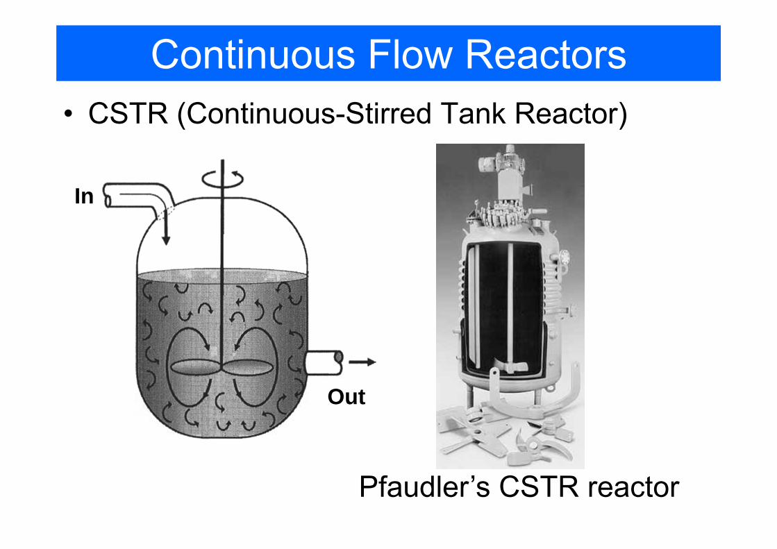
Continuous Flow Reactors• CSTR (Continuous-Stirred Tank Reactor)
Pfaudler’s CSTR reactor
In
Out

Continuous Flow Reactors• CSTR (Continuous-Stirred Tank Reactor)
0
Vj
j j i
dNF F rdV
dt− + =∫
=0, operation in a steady mode
• assuming perfect mixing, so• Reaction rate is the same through the volume• Conditions of exit stream are the same as in the reactor
0j j jF F r V− = − 0j j
j
F FV
r−
=−
Design equation of CSTR
0 0A A
A
v C vCVr−
=−
or
0jF
jF

Continuous Flow Reactors• Tubular reactor
• usually operates in steady state• primarly used for gas reactions • easy to maintain, no moving parts• produce highest yield• temperature could be difficult to control, hot spots might occur

Continuous Flow Reactors
• Tubular reactor– Reaction continuously progresses along the length of the reactor, so the
concentration and consequently the reaction rate varies in axial direaction– in the model of Plug Flow Reactor (PFR) the velocity is considered uniform and
there are no variation of concentration (and reaction rate) in the radial direction
– If it cannot be neglected we have a model of Laminar Flow Reactor.

Continuous Flow Reactors• PFR (plug flow reactor) – useful approximation of a tubular reactor
• For every slice of volume:
0 0j j iF F r V− + Δ = | |j V V j Vi
F Fr
V+Δ −
=Δ
ji
dFr
dV=
• From here, a volume required to produce given molar flow rate of product can be determined
0
Vj
j j i
dNF F rdV
dt− + =∫
0No accumulation

Continuos Flow Reactors• Design equation for PFR
• If we know a profile of molar flow rate vs. Volume we can calculate the
required volume to produce given molar flow rate at the outlet.
jj
dFr
dV=
j
j
dFdV
r= 0
0
j j
j j
F Fj j
F Fj j
dF dFV
r r= =
−∫ ∫

Continuous Flow Reactors
• Packed-Bed reactor – here the reaction takes place on the surface of catalyst
• reaction rate defined per unit area (or mass) of catalyst
( ) ( )mol A reacted /s g catalystAr′− = ⋅
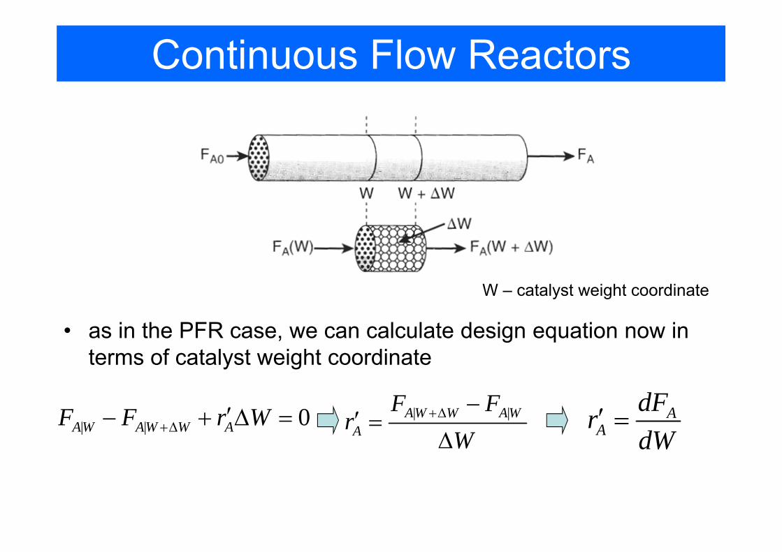
Continuous Flow Reactors
• as in the PFR case, we can calculate design equation now in terms of catalyst weight coordinate
W – catalyst weight coordinate
| | 0AW AW W AF F r W+Δ ′− + Δ = | |AW W AWA
F Fr
W+Δ −
′ =Δ
AA
dFrdW
′ =

Reactors Mole Balance: Summary

How we can use design equations: Example 1-1
• ProblemAn isomerization reaction A->B (first order reaction, k=0.23 min-1) is run in a tubular reactor with a constant volumetric flow rate v0= 10 l/min. Derive design equation, sketch concentration profile and determine the reactor volume required to achive 10% of A at the exit.
• SolutionFrom the mole balance for PFR:
Reaction rate law:
AA
dF rdV
=
A Ar kC− =
0A AdF dCv
dV dV=As the volumetric flow is kept constant:
0A
AdCv kCdV
= −Combining with the rate law:1
0
30 100A
A
CA
AC
v dCV dmk C
= − =∫

Sizing of reactors
Here we’ll find how to find the size of a reactor if the relation between the reaction rate and
conversion factor is known

Conversion in the reactors
• if we are interested in species A we can define the reactant A as the basis of calculation
aA bB cC dD+ ⎯⎯→ +
b c dA B C Da a a
+ ⎯⎯→ +
• conversion: Moles of A reactedMoles of A fedAX =
• maximum conversion for reversible reactions is the equilibrium conversion Xe.

Batch reactor design equations
• the equation can be integrated to find the time necessary to achieve required conversion
• the longer reactants spend in the chamber the higher is the degree of conversion
[ ] [ ]0Moles of A reacted A AN X= ⋅
[ ] [ ] [ ]0 0Moles of A in reactor, A A A AN N N X= − ⋅
0
( )AA
AA
dN r Vdt
dN dXNdt dt
− = −
= −0 ( )A A
dXN r Vdt
= −
Design equation for Batch Reactor

Design equations for flow reactors
• molar flow rate can be expressed asconcentration * volume rate
[ ][ ] [ ][ ]
[ ][ ]0
Moles of A fed Moles of A reactedtime Moles of A fedAF X =
[ ] [ ] [ ]0 0A A AF F X F− ⋅ =
[ ] [ ]0 0 0(1 ) (1 )A A AF F X C v X= − = −
[ ][ ] [ ][ ]0
Moles of A reactedtimeAF X =
Molar flow ratefed to the system
Molar flow rate of the consumption of A in the system
Molar flow rate of A leaving the system

Design equations for flow reactors• CSTR:
[ ] [ ]0 (1 )A AF F X= −
( )0 0A A A
A A exit
F F F XVr r− ⋅
= =− −
• Because the reactor is perfectly mixed, the exit composition is identical to the composition inside the reactor

Design equations for flow reactors• Tubular Flow Reactor (PFR):
[ ] [ ]0 (1 )A AF F X= −
00
X
AA
dXV Fr
=−∫
• to integrate we need to know rA depends on the concentration (and therefore on conversion)
AA
dFrdV−
− =0A
AF dXr
dV− =

Design equations for flow reactors• Packed-Bed Reactor: similar derivation, but W instead of V
[ ] [ ]0 (1 )A AF F X= −
00
X
A
A
dXW Fr
=′−
∫
• from this equation we can find weight of catalyst W required to achieve the conversion X
AA
dFrdW−′− =
0AA
F dXrdW
′− =
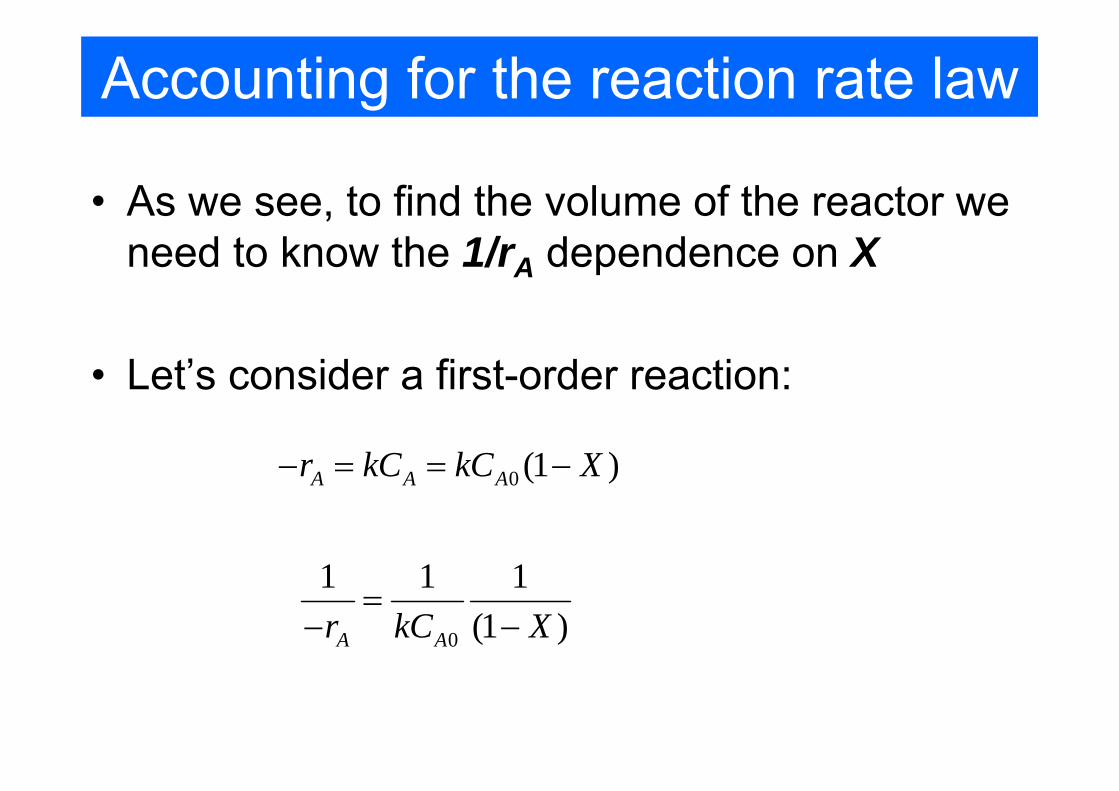
Accounting for the reaction rate law
• As we see, to find the volume of the reactor we need to know the 1/rA dependence on X
• Let’s consider a first-order reaction:
0 (1 )A A Ar kC kC X− = = −
0
1 1 1(1 )A Ar kC X
=− −

Levenspiel plot• reactor volume required is always reciprocal in
rA and proportional to X.
00
X
AA
dXV Fr
=−∫
0A
A
F XVr⋅
=−
PFR: CSTR:
• Levenspiel plot:

Example (2.2, p.48)• Reaction A→B described by the data below and the species A
enter the reactor at a molar flow rate of 0.4 mol/s:
• Calculate the volume necessary for 80% conversion

Example (2.2, p.48)• Solution:
– Based on the table the Levenspiel plot can be constructed
– The design equation for the CSTR:
( )0
1
A
A exit
FV Xr
=−
330.4 20 0.8 6.4mol m sV m
s mol⋅
= =

Example (2.3, p.50)• Calculate based on the same data the volume of PFR:
– Again, we construct the Levenspiel plot
– The design equation for the PFR:
0.8 300
1
2.165A
A
FV dX mr
= =−∫

Reactors in series• CSTR in series
– 1st reactor
0 1 1 1
1 0 0 1
0A A A
A A A
F F r VF F F X
− + =
= − 1 0 11
1A
A
V F Xr
=−
– 2nd reactor
1 2 2 2
2 0 0 2
0A A A
A A A
F F r VF F F X
− + == −
( )2 0 1 22
1A
A
V F X Xr
= −−
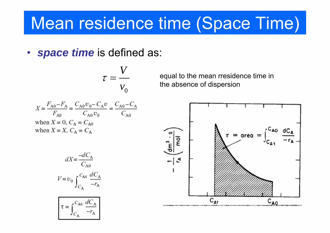
Mean residence time (Space Time)• space time is defined as:
0
Vv
τ = equal to the mean rresidence time in the absence of dispersion

Reactor design equations: Summary

Problems
• Class problem: – P1-6b (p.30): Calculate the volume of CSTR for
the conditions of example 1-1.– P2-7b (p.74)
• Home problems: – P2-5b– P2-6a ”Hippopotamus stomack”
http://www.engin.umich.edu/~cre/web_mod/hippo/index.htm