chem soc revresearch.chem.psu.edu/mallouk/articles/c2cs35246j.pdf · methane orindirectly via...
TRANSCRIPT

This journal is c The Royal Society of Chemistry 2013 Chem. Soc. Rev., 2013, 42, 2357--2387 2357
Cite this: Chem. Soc. Rev.,2013,42, 2357
Design and development of photoanodes forwater-splitting dye-sensitized photoelectrochemical cells†
John R. Swierk and Thomas E. Mallouk*
Dye sensitized solar cells (DSSCs) use low-cost materials, feature tunable molecular sensitizers, and
exhibit quantum efficiencies near unity. These advantageous features can be exploited in the context of
solar water splitting by functionalizing DSSCs with catalysts for water oxidation and reduction. This
article will cover the development of photoanodes for water splitting DSSCs from the perspective of
water oxidation catalysts, sensitizers, electron transfer mediators, photoanode materials, and system
level design. Within each section we will endeavor to highlight critical design elements and how they
can affect the efficiency of the overall system.
1. Introduction
Dihydrogen, the smallest and simplest molecule, plays anincreasingly important role in the global energy economy. In2010, over 40 million tons of hydrogen were produced globally,the vast majority used in the production of petrochemicals andammonia.1 Beyond these industrial applications, the demandfor hydrogen is expected to rise as it finds greater use as anenergy carrier. Unlike hydrocarbons, hydrogen gas producesonly water as a combustion product and can readily run anysystem currently using natural gas. The stored chemicalenergy in hydrogen can be efficiently converted to electricity
by air-breathing fuel cells.2 In applications that require carbon-based fuels, hydrogen can be used to form methane via theSabatier reaction, combined with carbon monoxide to makehydrocarbon fuels by the Fischer–Tropsch process, catalyticallyreacted with carbon dioxide to make methanol, or added toliquefied coal to make synthetic gasoline.3
Enabling a fuel economy based on hydrogen is however amajor challenge. Currently, hydrogen is produced directly frommethane or indirectly via electrolysis using electricity from non-renewable resources.1 A more sustainable approach would be toproduce hydrogen from renewable energy sources.4 Of therenewable energy sources, sunlight has enormous potential.Its power density is 1 kW m�2 on a clear day and the globalpotential of solar power is approximately 10 000 greater thanthe current primary power use (16 TW) of the entire world.4 In
Department of Chemistry, The Pennsylvania State University, University Park,
Pennsylvania 16802, USA. E-mail: [email protected]
† Part of the solar fuels themed issue.
John R. Swierk
John R. Swierk received his BS inChemistry and BSE in MaterialsScience & Engineering from theUniversity of Pennsylvania. In2008, he began his PhD at PennState under the supervision ofProfessor Thomas E. Malloukstudying electron transfer inwater splitting systems.
Thomas E. Mallouk
Thomas E. Mallouk received hisScB degree from Brown University(1977) and his PhD in Chemistryfrom the University of California,Berkeley (1983). He was apostdoctoral fellow at MIT(1983–1985). His researchfocuses on the synthesis,assembly, and applications ofnanoscale inorganic materials.
Received 8th July 2012
DOI: 10.1039/c2cs35246j
www.rsc.org/csr
Chem Soc Rev
REVIEW ARTICLE

2358 Chem. Soc. Rev., 2013, 42, 2357--2387 This journal is c The Royal Society of Chemistry 2013
this context, hydrogen can be liberated by splitting water intomolecular hydrogen and oxygen, either directly by photocata-lysis or in a photoelectrochemical process:
H2O - H2(g) + 1/2O2(g) (1)
The basic thermodynamic requirements for splitting waterare modest. It is an uphill reaction, requiring the input ofenergy, with a Gibbs free energy of 237.178 kJ mol�1. Consid-ered as an electrochemical potential, a minimum potential of1.229 V is required at 298 K. In principle any wavelength of lightshorter than 1 mm has enough energy to split the watermolecule, allowing for the use of the entire visible solarspectrum and much of the near-infrared, which together com-prise B80% of the total solar irradiance.5
How well photochemical water splitting transitions to realworld systems hinges on how efficiently photons are absorbedand used to form hydrogen. In real systems not all of the solarenergy available can be converted into a chemical fuel. Detailedbalance calculations can be used calculate a maximum theoreticalefficiency by considering various loss processes. Shockley andQueisser6 first developed this type of analysis for single junctionsilicon solar cells with many other authors extending it to multiplejunction cells7 and photochemical processes.5,8,9 All treatmentsbegin by assuming an ideal absorber, a material with a singlebandgap or absorption threshold (Ug) that absorbs all photonswith energy greater than Ug and absorbs no photons with energyless than Ug. As a consequence, some fraction of the solarspectrum with energy less than Ug is not used by the photo-chemical system. It is also assumed that excited electrons rapidlylose energy in excess of Ug by thermalization and relax back to thebandgap or absorption edge. Thus much of the energy fromphotons with energy greater than Ug is lost to the system as heat.Considering only these two loss mechanisms would mean that atmost an ideal system could convert B50% of incident solarenergy into a chemical fuel. However a third loss mechanism isintroduced because the maximum extractable work from a photo-voltaic or photochemical system is always less than Ug. This isbecause a sea of electrons in the ground state surrounds eachelectron in an excited state, creating significant entropy of mixingand introducing an unavoidable thermodynamic loss parameter.Finally, a small fraction of excited states must decay radiatively inorder to maintain a high chemical potential. When these lossmechanisms are taken together, a single absorber with Ug = 1.59eV has a maximum efficiency of 30.6% under ideal conditions.Multiple absorber systems can exceed this limit, though thetheoretical efficiency depends on how many absorbers are used.Realistically attainable efficiencies are well below these theoreticallimits due to electron transfer losses, catalyst overpotentials, andreflection losses. Fig. 1 demonstrates how additional processescan contribute to energy loss.
2. Water splitting systems
Nature provided an enduring blueprint for photochemical watersplitting with the evolution of photosynthesis 2.4–3 billion years
ago.10 Algae and higher green plants use two coupled photosys-tems, photosystem II and photosystem I, to absorb light and splitwater into oxygen and NADPH. Briefly, a series of light harvestingpigments absorb visible light and within one picosecond funnel theexcitation energy to a P680 chlorophyll dimer located within thereaction center protein of photosystem II. The excited P680 passesan electron to a nearby pheophytin, a chlorophyll molecule lackinga Mg2+ ion, which is then followed by rapid electron transfer to aplastoquinone.11 Within 200 ps, the electron is physically separatedfrom the oxidized P680+ by a distance of about 26 Å giving a charge-separated state stable for hundreds of microseconds.12 A redoxactive tyrosine group is oxidized by P680+ and mediates the rapidcharge transfer steps at P680 with the slow oxidation of the oxygen-evolving complex (OEC). At the heart of the OEC lies an oxo-bridgedcluster of one calcium and four manganese ions. The OEC accu-mulates four oxidizing equivalents before releasing oxygen andbeing regenerated to its reduced resting state.13 As the OEC is beingoxidized, the electrons from P680 leave photosystem II via anotherplastoquinone and cytochrome b6f molecule to make their way tophotosystem I. Here another chlorophyll, P700, is excited andoxidized, with electrons being funneled down a charge transferchain until they are used to reduce NADP + to NADPH. Theelectrons from photosystem II regenerate the oxidized P700. Over-all, two photons are required for every electron transferred(Fig. 2).14
Despite all of the exquisite complexity and sophistication ofnatural photosynthesis, plants are optimized for reproductivesuccess and not efficient energy conversion. For example, P680and P700 have significant spectral overlap, meaning that a largeportion of the usable solar spectrum is wasted. Likewise, plants
Fig. 1 Energy diagram demonstrating energy losses in a water splitting systemsensitized by a molecular dye. Reproduced from ref. 5 with permission from TheRoyal Society of Chemistry.
Review Article Chem Soc Rev

This journal is c The Royal Society of Chemistry 2013 Chem. Soc. Rev., 2013, 42, 2357--2387 2359
absorb more light energy than they are able to process with upto 80% of absorbed energy being discarded.16 Additionally,photorespiration can be responsible for a loss of up to 25%of the stored energy in plants.17 These factors limit the overallefficiency of photosynthesis to less than 10% at low light levels,and 1–3% in full sunlight.18–21 While the natural photo-synthetic apparatus provides inspiration for the design of efficientbiomimetic systems, plant photosynthesis itself is unlikely to bebioengineered to the level where it can be competitive with othercommodity fuel sources (including photovoltaics coupled toelectrolyzers).22 Among the major impediments to such improve-ment is the mass transport limit of atmospheric CO2. Because ofthe low concentration of CO2 in the atmosphere (390 ppm),photosynthesis is forced to operate at low concentrations ofCO2. The equivalent current density that a photosynthetic systemcan provide in atmospheric CO2 can be calculated from the large-area, boundary-layer mass-transport limit for atmospheric CO2
capture (400 tC per ha year).23 This mass-transport limit translatesto an equivalent current density of 3.7 mA cm�2, assuming thatthe reduction of CO2 to carbohydrates involves four electrons percarbon atom. The free energy stored per mole of carbon is�480 kJin glucose, a representative carbohydrate product. It follows thatthe power that can be stored in carbohydrates at the masstransport limit is 4.6 mW cm�2, which corresponds to a max-imum power conversion efficiency of 4.6% (the power input fromthe sun being B100 mW cm�2). However, like any other energyconversion system, photosynthesis cannot operate efficiently atthe mass transport limit because of concentration polarization ofCO2. Some of the stored energy is also needed for respiration inliving plants.24 Considering these loss mechanisms, the CO2
mass-transport limit corresponds closely to the B1–3% efficiencyof plant photosynthesis in full sun. In contrast, efficient solarenergy conversion devices such as crystalline silicon cells, whichoperate at quantum yields (electrons generated per photonabsorbed) near unity, have power conversion efficiencies andcurrent densities that are approximately one order of magnitudehigher than photosynthesis. For example, the short-circuitcurrent density at a 24.4% efficient silicon solar cell in full sun
is 42.0 mA cm�2.2,25 It follows that artificial photosyntheticsystems will need to be more like the latter kind of device,ultimately operating near unit quantum efficiency, in order tobe competitive with other forms of commodity energy.
The development of artificial photosynthetic systems canroughly be divided into two general approaches, photocatalysisand photoelectrohemical cells (PEC). Any material that canboth absorb light and perform water oxidation or reductioncan be considered a photocatalyst, though in the context ofphotochemical water splitting the term is more narrowlyapplied. Overall water splitting by a photocatalyst typicallyrefers to a photoactive colloidal suspension, which produceshydrogen and oxygen in close proximity to each other. PECs canperform a variety of electrochemical half-reactions, and inregenerative cells (like the DSSC), the anode reaction is simplythe reverse of the cathode reaction and the cell generateselectricity. Water-splitting PECs are a special case where hydrogenis made at the cathode and oxygen at the anode. These electrodesare physically well separated from each other, in contrast to thesituation in photocatalysis. Many of the materials that are used asphotocatalysts are also employed as photoelectrodes in PECs. Thisapproach is reminiscent of the compartmentalization of oxygenand NADPH production in natural photosynthesis.
More than 130 inorganic materials have been identified aspossible photocatalysts for water splitting.26 Early work onphotocatalysts focused on titanium dioxide and demonstratedthe production of hydrogen and oxygen using UV light and aco-catalyst.27,28 Photocatalysts with enhanced visible lightabsorption, such as BiVO4, produce oxygen photochemicallywith visible light, but require the use of a sacrificial Ag+ electronacceptor because the conduction band potential is too positivefor hydrogen evolution.29,30 Overall water splitting using a(Ga1�xZnx)(N1�xOx) photocatalyst modified with rhodium andchromium mixed oxide was achieved by Domen and co-workers.31,32
An early version of this system had a quantum yield of 2.5% with420 nm excitation,33 which was later improved to 5.9%.33 In generalthough, these materials have relatively wide bandgaps and poorabsorption characteristics. For example the onset of absorption in
Fig. 2 (A) Redox potentials with photosystem II reaction center. (B) Photosystem II reaction complex after light excitation with surrounding protein structureremoved. Reproduced from ref. 15 with permission from The Royal Society of Chemistry.
Chem Soc Rev Review Article

2360 Chem. Soc. Rev., 2013, 42, 2357--2387 This journal is c The Royal Society of Chemistry 2013
(Ga1�xZnx)(N1�xOx) is 510 nm, and the quantum yield is lowdue to electron–hole recombination, another problem typical ofphotocatalytic systems.
The first demonstration of photoelectrochemical watersplitting used an oxygen-evolving rutile TiO2 photoanode andhydrogen evolving platinum cathode.34 Rutile has a bandgap(3.0 eV) that limits light absorption to the ultraviolet, so thequantum yield of water splitting in sunlight is typically below2%. Many groups have worked to extend the visible absorptionof TiO2 via doping with transition metal35,36 and main groupelements.37,38 While dopants do increase visible light absorp-tion by introducing localized color centers, or in some cases byshifting the valence and/or conduction band edges, doping alsointroduces a high density of trap states and can decrease holemobility leading to increased electron–hole recombination.39
Other metal oxides such as WO3,40 BiVO4,41 and Fe2O342 have
also been investigated as possible visible light absorbing photo-anodes, but are generally limited to wavelengths shorter than500 nm, exhibit poor hole transport properties, and requirelarge bias voltages. Some recent work has focused on thedevelopment of metal oxide heterostructures as a route toimproving the performance of these photoanode materials.43
Oxynitrides photoanodes offer an alternative strategy forvisible light absorption. Introduction of nitrogen atoms intooxygen sites shifts the valence band edge to more negativepotentials through hybridization of N 2p and O 2p orbitals.Domen and co-workers have demonstrated high quantum efficiency(IPCE = B76% at 400 nm) with TaON based photoanodes, thoughthe application of an external bias and a co-catalyst wererequired.44,45 Other oxynitrides such as LaTiO2N46 and SrNbO2N47
have similarly been studied as photoanodes.An alternative strategy for PECs is to decouple the light
absorption and catalytic functions of the electrode. In thesimplest form of this concept, a semiconductor photovoltaicis coupled to oxygen- and hydrogen-evolving catalysts. An earlydemonstration of this approach was photolysis of HBr and HIon a silicon p–n junction coated with aluminum. This system,developed in the 1970’s by Texas Instruments, used concentri-cally doped silicon microspheres. Because of the small size ofthese spheres, inexpensive metallurgical silicon could beused.48–50 Bipolar series arrays of TiO2
51 and CdSe/CoS52 photo-electrochemical cells were subsequently demonstrated to driveoverall water splitting, although in both cases efficiency was low(r1%). The CdSe/CoS-based array was designed to avoid thewell-known stability problem of oxygen-evolving photoanodesbased on semiconductors with visible light bandgaps. In thebipolar CdSe/CoS cell, the chalcogenide portion of the cell wasin contact with a stabilizing polysulfide solution and preventedfrom contacting the aqueous side of the cell. Khaselev andTurner53 later developed a monolithic system with an overallwater splitting efficiency of 12.4% by combining an oxidativelyunstable GaAs p–n junction with a cathodically protectingp-type GaInP2 layer connected through a tunnel junction. Lichtand co-workers54 achieved the highest reported water splittingefficiency, 18.3%, by extending this multijunction approach toinclude as many as 10 components. More recently, arrays of
silicon microwires have been used to drive the hydrogen-evol-ving half cell of a water splitting system,55,56 although as single-junction devices they lacked the photovoltage needed forunassisted water splitting. Multijunction wires57 coupled toelectrocatalysts could in principle provide a sufficient photo-voltage to drive the overall reaction. In related work, Nocera andcoworkers58 recently demonstrated a 4.7% efficient water-splittingPEC by coupling a monolithic three-junction amorphous silicon–germanium photovoltaic cell to a cobalt phosphate oxygen evolvingcatalyst and a Ni–Zn–Mo hydrogen evolving catalyst (Fig. 3). Thissystem is interesting because it uses only abundant elements andbecause the cathode catalyst, unlike the noble metals used in manywater-splitting systems, is relatively insensitive to impurities inthe water.
An ideal photoelectrochemical water splitting cell wouldcombine the low cost of terrestrially abundant materials withthe high quantum efficiency of a photovoltaic cell. In addition,tunability of the absorption characteristics and the use ofmultiple absorbers is desirable in order to ‘‘evolve’’ towards asystem that can use the solar spectrum efficiently. Dye sensitizedsolar cells (DSSCs) are made from inexpensive TiO2 anodes sensi-tized with visible light absorbing dyes.59 The latter are tunable bymolecular design to cover different parts of the solar spectrum, andtandem arrangements with multiple dyes60,61 and dyes combinedwith semiconductor absorbers have been demonstrated.62–66 Thequantum efficiency of DSSCs is near unity for charge injection intothe semiconductor electrode.
When employed as photovoltaics, DSSCs use a redox shuttleto complete the photoelectrochemical circuit. If the dye isinstead coupled to a water oxidation catalyst, water can serveas an electron source for regenerating the oxidized dye.67 In thisarrangement, the photoanode of the dye cell oxidizes water,
Fig. 3 Monolithic wireless water splitting device developed by Nocera and co-workers. Migration of anions and cations occurs in the direction shown at thebottom of the figure.
Review Article Chem Soc Rev

This journal is c The Royal Society of Chemistry 2013 Chem. Soc. Rev., 2013, 42, 2357--2387 2361
and proton reduction to hydrogen occurs at that cathode. So farsuch systems employ only one light absorber and an externalbias voltage must be applied because the photovoltage generatedby the dye is not sufficient to drive overall water splitting. Inprinciple, these dye-sensitized photoanodes could be coupled tocomplementary photocathodes to effect water splitting in an eight-photon, four-electron process that is mimetic of the two coupledphotosystems in plant photosynthesis. For example, Kaschak et al.demonstrated photoinduced electron transfer from a porphyrin topolyviologen electron acceptor using a semiconducting nanosheetto mediate the forward charge transfer.68 Though not explored inthe paper, the potential of the polyviologen is sufficiently negativeto drive hydrogen evolution. In principle this system, or onesimilar, could be grown upon a conductive support to prepare aphotocathode. A possible dual absorbing photoelectrochemicalcell is sketched in Fig. 4. This review will focus on the recentdesign and development of the dye-sensitized photoanodes ofsuch water splitting systems.
3. Dye-sensitized photoanodes
Dye-sensitized water splitting cells are comprised of four majorcomponents: visible light-absorbing sensitizer, water oxidationcatalyst (WOC), water reduction catalyst, and semiconductoranode. Electron transfer mediators can be added and choice ofpH and buffer must be considered. Here, we will focus on thedesign of WOCs, sensitizers, mediators, and electrodes andreview examples that have been shown to participate in water
oxidation reactions either with sacrificial reagents or underelectrochemical/photoelectrochemical conditions. Because themajor bottleneck in the design of efficient and durable watersplitting cells is the catalytic four-electron oxidation of water,we do not discuss here the rapidly developing science ofcatalysts and sensitizers for water reduction and refer theinterested reader to several recent reviews of that topic69,70
3.1 Water oxidation catalysts
An ideal WOC must collect four oxidizing equivalents peroxygen molecule generated, facilitate the formation of dioxygen,and be chemically stable; for practical use over a 20–30 year systemlife, the catalyst should be active for approximately 109 cycles orself-repairing. Catalysts are classified as either molecular or parti-cle-based. Molecular WOCs, which are often studied in solution ashomogeneous catalysts, can be more readily characterized struc-turally and are amenable to detailed kinetic/mechanistic studies.These benefits of molecular catalysts come with a price, namelysynthetic complexity and often a lack of stability. Conversely,heterogeneous, nanoparticle-based catalysts are simpler to prepareand are more chemically robust, but their structural and mecha-nistic characterization is more challenging.
The utility of WOCs can be quantified by three parameters:the turnover number (TON), turnover frequency (TOF), andoverpotential at the desired TOF. The TON of a catalystdescribes how many cycles it is able to cycle through beforebecoming inactive. TOF is the number of cycles a catalystundergoes per unit time. Ideally the TOF of the catalyst should
Fig. 4 Scheme of an 8-photon, 4-electron water splitting system.
Chem Soc Rev Review Article
2362 Chem. Soc. Rev., 2013, 42, 2357--2387 This journal is c The Royal Society of Chemistry 2013
substantially exceed the flux of photons in full sun in order toobtain a high quantum yield. Following the analysis of Frei andJiao,71 a lower limit for TOF can be calculated. Integrating the solarphoton flux over wavelengths shorter than 1000 nm gives approxi-mately 4290 mE m�2 s�1 or 2600 photons nm�2 s�1.5 Assuming adual absorber system, eight photons must be absorbed for eachmolecule of oxygen produced. At a catalyst coverage of one site pernanometer squared, this gives a minimum TOF of 325 s�1.Complete light absorption by dyes, which usually have extinctioncoefficients in the range of 104–105 M�1cm�1 (B10�3–10�2 cm�2 ata coverage of 1 � 10�10 mol cm�2) typically requires porouselectrodes with surface areas that are hundreds of times largerthan their geometrical area, relaxing the TOF requirement for thedye–catalyst dyad to approximately 3 s�1. However, as detailedbelow, artificial photosynthetic systems generally require very fastelectron transfer from the WOC in order to compete with fasterback electron transfer processes, so in practice much higher TOFsare needed.
The overpotential is the excess energy per unit charge thatmust be added to drive the process as the catalyst cycles. Inpractice this is often measured as the difference between theonset of water oxidation and the formal potential for wateroxidation at the pH where the cell is operated. Common over-potentials for WOCs are 0.3 to 0.7 V, though WOCs with loweroverpotentials exist.72 The high overpotential of the four-electron water oxidation reaction is one of the major reasonswhy real system efficiencies cannot meet theoretical efficiencyand much work is being devoted to developing catalysts withlower overpotentials at adequate TOFs.
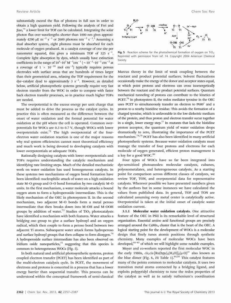
Rationally designing catalysts with lower overpotentials andTOFs requires understanding the catalytic mechanism andidentifying rate limiting steps. Much of the detailed mechanisticwork on water oxidation has used homogeneous catalysts. Inthese systems two mechanisms of oxygen bond formation havebeen identified: nucleophilic attack of water on a high oxidationstate M–O group and O–O bond formation by two catalytic M–Ounits. In the first mechanism, a water molecule attacks a boundoxygen atom to form a hydroperoxide intermediate. This is thelikely mechanism of the OEC in photosystem II. In the secondmechanism, two adjacent M–O bonds form a metal peroxointermediate that then breaks down into M–OH and M–OOHgroups by addition of water.73 Studies of TiO2 photocatalystshave identified a mechanism with both features. Water attacks abridging oxo group to give a surface hydroxyl and an oxygenradical, which then couple to form a peroxo bond between twoadjacent Ti atoms. Subsequent water attack forms hydroperoxoand surface hydroxyl groups that then collapse to form dioxygen.74
A hydroperoxide surface intermediate has also been observed oniridium oxide nanoparticles,75 suggesting that this species iscommon to heterogeneous WOCs (Fig. 5).
In both natural and artificial photosynthetic systems, protoncoupled electron transfer (PCET) has been identified as part ofthe multi-electron catalysis cycle. In PCET, the movement ofelectrons and protons is concerted in a process that has a lowerenergy barrier than sequential transfer. This process can beunderstood within the conceptual framework of semi-classical
Marcus theory in the limit of weak coupling between thereactant and product potential surfaces. Solvent fluctuationsoccasionally make the energy of the donor and acceptor states equal,at which point protons and electrons can cross isoenergeticallybetween the reactant and the product potential surfaces. Quantummechanical tunneling of protons can contribute to the kinetics ofPCET.76 In photosystem II, the redox mediator tyrosine in the OECuses PCET to simultaneously transfer an electron to P680+ and aproton to a nearby histidine residue. This avoids the formation of acharged tyrosine, which is unfavorable in the low dielectric mediumof the protein, and thus proton and electron transfer occur togetherin a single, lower energy step.77 In mutants that lack the histidineproton acceptor, the quantum yield of water oxidation dropsdramatically to zero, illustrating the importance of the PCETmechanism.78,79 PCET has also been identified in many artificialphotosynthetic systems. Because water oxidation catalysts mustmanage the transfer of four protons and electrons for eachmolecule of oxygen generated, efficient proton management isa key for a good WOC.80
Four types of WOCs have so far been integrated intodye-sensitized photoanodes: molecular catalysts, cubanes,polyoxometalates, and heterogeneous catalysts. As a startingpoint for comparison across different classes of catalysts, wereview TOF, TON, and overpotential data for representativecatalysts. Wherever possible we have presented numbers givenby the authors but in some instances we have calculated thevalues from published data. In general, TOF and TON arecalculated assuming every metal center is catalytically active.Overpotential is taken at the initial onset of catalytic wateroxidation current.
3.1.1 Molecular water oxidation catalysts. One attractivefeature of the OEC in PSII is its remarkable level of structuralorganization. Essential amino acid functional groups are preciselyarranged around the CaMn4 cluster that is the heart of the OEC. Alogical starting point for the development of WOCs is a moleculardesign that finely tunes atomic positions through syntheticchemistry. Many examples of molecular WOCs have beendeveloped,81–83 of which we will highlight some notable examples.
Meyer and co-workers reported the first molecular WOC inthe early 1980s, cis,cis-[Ru(bpy)2(H2O)]2(m-O)4+ also known asthe blue dimer (Fig. 6, #1 Table 1).84,85 This catalyst featuresmany of the points common to molecular catalysts. It uses twotransition metal atoms connected by a bridging ligand, andexploits polypyridyl chemistry to tune the redox properties ofthe catalyst as well as to satisfy ruthenium’s coordination
Fig. 5 Reaction scheme for the photochemical formation of oxygen on TiO2.Reprinted with permission from ref. 74. Copyright 2004 American ChemicalSociety.
Review Article Chem Soc Rev

This journal is c The Royal Society of Chemistry 2013 Chem. Soc. Rev., 2013, 42, 2357--2387 2363
sphere. The blue dimer has an overpotential of B470 mV,demonstrating the moderate overpotentials typical of rutheniumdimers. Through its easily cleaved bridging oxo group, it alsoexemplifies a major pitfall of molecular catalysts, instability.With this unstable oxo group, a TON of B13 and TOF of0.004 s�1 were obtained.86,87 If a rigid bridging ligand is usedinstead of oxygen the TON can surpass 10 000 (#5 Table 1).88 It isimportant to note that molecular catalysts are often studied notunder photochemical or electrochemical conditions but using achemical oxidant, such as Ce(IV), to drive the water oxidationreaction. Chemical oxidants avoid the complication of competingforward and back electron transfer pathways as well as directwater oxidation at electrode surfaces. While these reagentssimplify the kinetics of water oxidation, the concentration of theoxidant can be significantly higher than in experiments in whichthe reaction is driven electrochemically or photochemically, lead-ing to artificially high TOFs and TONs. Additionally, sacrificialreagents can generate highly oxidizing species, in some cases inexcess of 3.45 V vs. NHE.89 These species can lead to undesirableside reactions and complicate the overall kinetics.
In parallel with dinuclear catalysts, single-site catalysts havealso been developed. Single-site catalysts avoid some of thestability issues encountered with binuclear catalysts, thoughtheir ligands are still susceptible to oxidative degradation.Thummel and co-workers developed the first mononuclearruthenium complexes with high turnover rates as WOCs(Fig. 6).90 Initially, the ruthenium center is in the +2 oxidationstate with a coordination number of 6 and a total electron countof 18. Two oxidizing equivalents increase the oxidation state ofruthenium to +4, leaving the highly electrophilic metal open toattack by water. Two more oxidizing equivalents give a Ru(VI)doubly bound to an oxygen atom. This complex undergoes waternucleophilic attack to produce a peroxo intermediate that thenloses a proton to oxygen.91 An interesting feature of the complexthat is reminiscent of the OEC in PSII is hydrogen bondingbetween a bound water molecule and a free nitrogen atom in thenapthyridine ring, which helps stabilize the complex (Scheme 1).
Single site ruthenium catalysts92,92 developed by the Meyergroup have likewise exploited polypyridyl chemistry to operate
at lower overpotentials than dinuclear catalysts (280–377 mV vs.NHE) and with oxidant-limited TONs (#9–10 Table 1). A singlesite ruthenium(II) complex was suspended in Nafion and usedas a WOC in a dye sensitized PEC (#11 Table 1).93 A relativelylow TON of 16 and TOF of 27 h�1 were measured for this systemat neutral pH. Recently, a single site ruthenium catalyst with aTOF of greater than 300 s�1 was reported.94 This TOF wasachieved at very high molar concentrations of Ce(IV) and isprobably not representative of the catalyst performance underphotochemical conditions.
In 2008, a new class of molecular iridium WOCs wasintroduced. The first of these WOCs, a family of cyclometalatediridium complexes, was synthesized by Bernhard and coworkers(#12 Table 1).95 These catalysts are synthetically simple, easilytunable, highly soluble in water, and chemically robust due tostrong carbon–iridium bonding. An extension of this approachuses electron-donating Cp* ligands to stabilize high oxidationstate Ir centers.96,97 Of particular relevance to dye sensitizedphotoanodes, Cp*–Ir complexes can be functionalized withcarboxylic acids and other ligating groups for attachment tometal oxide surfaces.98
Some success with molecular manganese WOCs has beenachieved. Limburg, Brudvig, and Crabtree106 prepared Mncomplexes with dipicolinate and 2,20:60,20 0-terpyridine ligandsthat generated oxygen when exposed to oxone. It was proposedthat these complexes initially formed an oxo-linked dimerbefore decomposing to form permanganate (Fig. 7). A subse-quent study108 examined the behavior of the terpyridine dimerin sodium hypochlorite and found that a MnVQO species wasthe key intermediate in the formation of oxygen. Stoichiometricoxygen evolution from a MnIII porphyrin dimer was observed byNaruta and co-workers.109,110 Individually, the MnIII porphyrinswere not able to generate oxygen, but when held in a fixedgeometry by a 1,2-substituted phenyl ring, oxygen evolution wasobserved. They also identified a MnVQO intermediate andpostulated that the O–O bond was formed either by nucleophilicattack on this species or via a coupling of two oxo groups. Recently, atetra-sulfonic acid functionalized MnIII porphyrin was incorporatedinto a poly(terthiophene) film and demonstrated catalytic behavior
Fig. 6 (Left) Blue dimer developed by Meyer and co-workers; (Right) single site ruthenium WOC developed by Thummel. Reprinted with permission from ref. 90.Copyright 2005 American Chemical Society.
Chem Soc Rev Review Article

2364 Chem. Soc. Rev., 2013, 42, 2357--2387 This journal is c The Royal Society of Chemistry 2013
with an apparently low overpotential at pH = 7 (B90 mV).111
The authors postulated that catalytic behavior comes from thefraction of porphyrin molecules in the film that are in closeenough proximity to mimic the behavior of the Naruta dimer.Detailed reviews on molecular Mn WOCs112,113 and on theMn-based15 OEC in PSII have recently been published.
Tetraamido iron-centered molecular WOCs were recently intro-duced by Ellis et al.114 Using Ce(IV) as a chemical oxidant, theyobserved biphasic behavior with an initial rapid release of oxygen,followed by steady oxygen evolution over the course of hours.Building upon those initial findings, Fillol et al. studied a seriesof iron coordination complexes for oxygen evolution activity.107
When two adjacent, labile sites were present in the catalyst, oxygenevolution was observed. With trans sites or a single site, therewas no activity. They also proposed a catalytic cycle that involveswater nucleophilic attack on an Fe(V) oxo group to give a peroxointermediate that releases oxygen upon subsequent oxidation.
A molecular cobalt catalyst, [CoII(qpy)(OH2)]2+ (qpy =2,20:60,20 0:60 0,20 0-quaterpyridine), was shown by Leung et al. toundergo chemical and photochemical water oxidation at pH > 8in the presence of [Ru(bpy)3]2+/S2O8
2�. The complex exhibitedmore than 330 turnovers and using [Ru(bpy)3]3+ as a chemicaloxidant, a TOF of 4 s�1. The onset of water oxidation occurredat an overpotential of B250 mV.115
One of the most advantageous aspects of molecular WOCs isthe ability to add specific functionality to the catalyst. Wada et al.103
developed a ruthenium dimer bridged with an anthracence back-bone functionalized with two terpyridines to bind the rutheniumatoms (Fig. 8, #7 Table 1). Notably, this catalyst used 3,6-di-tert-butyl-1,2-benzoquinone a ligand on the ruthenium to introduce quinonefunctionality. As the SbF6 salt, this catalyst could be depositedonto an ITO substrate and catalyze 30 000+ turnovers of waterelectrolysis at the mildly acidic pH of 4 with a moderate over-potential (B400 mV). The quinones play an active role in the
Scheme 1 Mechanism for water oxidation by single site ruthenium WOC. Reprinted with permission from ref. 91. Copyright 2008 American Chemical Society.
Table 1 Comparison of selected molecular water oxidation catalysts
Catalyst Oxidant TOF (s�1) TON Overpotential (mV vs. NHE) Ref.
1 cis,cis-[Ru(bpy)2(H2O)]2(m-O)4+ Ce(IV) 0.004 13 474 84, 852 in,in-[(Ru(tpy)(H2O)]2(m-bpp)3+, Ce(IV) 0.86 512 993 trans,trans-[Ru2(L1)(4-CH3O-py)4Cl]3+ Ce(IV) 3.8 � 10�5 689 1004 [Ru2(L2)(4-CH3-py)6]1+ Ce(IV) 0.24 1690 424 1015 [Ru2(L3)(4-CH3-py)4Cl]1+ Ce(IV) 1.2 10 400 330 886 [Ru(tpy-PO3H2)(H2O)2]2O4+ 1.25–1.5 V vs. Ag/AgCl 1.8 414 1027 [Ru2(OH)(3,6-tBu2qui)2(btpyan)]2+ 1.7 V vs. Ag/AgCl 0.232 33 500 405 1038 trans-[Ru(L4)(4-CH3-py)2(H2O)]2+ Ce(IV) 0.0028 260 909 [Ru(tpy)(bpm)(OH2)]2+ Ce(IV) 0.019 7.5 377 9210 [Ru(Mebimpy)(bpy)(OH2)]2+ Ce(IV) 0.0067 7.5 280 10411 Ru(6,60-dcbpy)(pic)2 RuP 0.0069 15 330 10512 [Ir(ppy)2(OH2)2]+ Ce(IV) 0.004 2490 185 9513 Cp*Ir(ppy)Cl Ce(IV) 0.167 >1500 585 9614 Cp*Ir(30-ppy)Cl ZnCCPP 0.001 0.066 185 9815 [Mn(dpa)2]� Oxone 8.3 � 10�6 0.6 10616 [Mn(tpy)]3+ Oxone 0.00014 >50 10617 [Fe(OTf)2(mcp)]2+ Ce(IV)/NaIO4 0.23 >1050 107
1. bpy = 2,20-bipyridine; 2. tpy = 2,20:60,20 0-terpyridine, bpp = bis(2-pyridyl)-3,5-pyrazolate; 3. L1 = 3,6-bis[60-(10 0,80 0-napthyrid-20 0-yl)pyrid-20-yl]-pyridazine, 4-CH3O-py = 4-methoxypyridine; 4. L2 = 3,6-bis-(60-carboxypyrid-20-yl)-pyridazine, 4-CH3-py = 4-methylpyridine, TOF calculated usinginitial rate of oxygen evolution; 5. L3 = 1,4-bis(60-COOH-pyrid-20-yl)phthalazine; 6. tpy-PO3H2 = 40-phosphonato-2,20:60 0,20 0-terpyridine; 7.3,6-tBu2qui = 3,6-di-tert-butyl-1,2-semiquinone, btpyan = 1,8-bis(2,20:60,20 0-terpyridyl)anthracene, TOF represents a lower limit; 8. L4 = 4-tert-Butyl-2,6-di([10,80]-naphthyrid-20-yl)pyridine; 9. bpm = 2,20-bipyrimidine, TOF calculated from initial O2 evolution rate; 10. Mebimpy = 2,6-bis(1-methylbenimidazol-2-yl)pyridine, TOF calculated from initial O2 evolution rate; 11. 6,60-dcbpy = 6,60-dicarboxylic acid-2,20-bipyridine, pic =4-picoline, RuP = [Ru(bpy)2(4,40-diphosphonic acid-2,20-bipyridine)]3+ photoelectrochemically generated; 12. ppy = 2-phenylpyridine; 13. Cp* =pentamethylcyclopentadienyl, TON is number of turnovers in 5.5 hours; 14. 30-ppy = 30-carboxy-2-phenylpyridine, ZnCCPP = Zinc 5-(4-carbomethoxyphenyl)-15-(4-carboxyphenyl)-10,20-bis(pentafluorophenyl) photoelectrochemically generated; 15. dpa = dipicolinate; 17. OTf =trifluoromethanesulfonate, mcp = (N,N0-dimethyl-N,N0-bis(2-pyridylmethyl)-cyclohexane-1,2-diamine).
Review Article Chem Soc Rev

This journal is c The Royal Society of Chemistry 2013 Chem. Soc. Rev., 2013, 42, 2357--2387 2365
catalytic cycle, switching between quinone and semiquinoneoxidation states, providing a pathway for proton coupled elec-tron transfer, and allowing the ruthenium centers to stay in thelow Ru(II)/Ru(III) oxidation states. Interestingly, the monoruthe-nium analog does not show activity nor does an analog in whichthe benzoquinone ligand has been replaced with 2,20-bipyridine.This demonstrates that the ruthenium centers act in concertwith the quinone ligands to split water.
Before leaving the topic of molecular WOCs, it is importantto note that in the study of these catalysts, care must be takento identify the active catalytic species. Decomposition of themolecular species to form an active heterogenous catalyst isa common issue with molecular WOCs.116–119 A detailed
discussion of the techniques used to identify the active formof the catalyst is beyond the scope of this review, but theinterested reader is directed to a detailed review by Widegrenand Finke120 as well as a recent article by Schley et al.121
3.1.2 Cubanes. Over the last decade a class of homo-geneous catalysts based on the cuboidal structure of the activeCaMn4 core in photosystem has been developed. Generallycubanes have the core structure [M4O4]6+ or 4+ with six to eightbidentate ligands helping to hold it together. Dismukesand coworkers first demonstrated gas phase photochemicaloxygen evolution from Mn4O4(PPh2)6 (1, Fig. 9) under UV
Fig. 7 (Left) Manganese terpyridine dimer introduced by Limburg et al., (Right) Naruta’s porphyrin dimer catalyst.
Fig. 8 [Ru2(OH)(3,6-tBu2qui)2(btpyan)](SbF6)2 where 3,6-tBu2qui = 3,6-di-tert-butyl-1,2-semiquinone and btpyan = 1,8-bis(2,2 0:60 ,20 0-terpyridyl)anthracene.
Fig. 9 Mechanism of photochemical O2 formation and release (l = 350 nm) inthe gas phase. Reproduced from ref. 124 with permission from The Royal Societyof Chemistry.
Chem Soc Rev Review Article

2366 Chem. Soc. Rev., 2013, 42, 2357--2387 This journal is c The Royal Society of Chemistry 2013
illumination.122,123 It was proposed that a cationic species,[Mn4O4(PPh2)5]+ (2), is initially formed. The flexibility of 2 allowsthe two manganese atoms on the open face to move apart due torepulsion. As the distance between the two manganese atomsincreases, the pair of oxygens bridging between the two arebrought into contact. This allows a peroxo species (3) to developas a bond between the two oxygen atoms is formed. Movingfrom species 2 to 3 is the rate-limiting step in the formation ofdioxygen because of the strain introduced in flexing the struc-ture. Following the formation of 3 a superoxo species (4) forms,which releases O2 to give the open ‘‘butterfly’’ (5) conformation.Via the uptake of two new water molecules and proton coupledelectron transfer, 5 is regenerated to the starting state.
Using Nafion as a support, a PEC with Mn4O4((p-OMe–C6H4)PO2)6 as the WOC was developed and showed sustainedwater oxidation photocurrent over a period of 10 hours underUV illumination. Based on the total photocurrent, a TONof greater than 1000 turnovers was reported, with TOFs from0.014 s�1 to 0.075 s�1 (Table 2).125 This approach was extendedto use visible light by the addition of ruthenium sensitizer126
and by coupling to two DSSCs in series.127 With the Nafionsupport, water oxidation by the Mn cubane was possible in thecondensed solution phase. The authors postulated that theNafion may have provided a stabilizing, protecting influenceon the oxidized cubane. This conclusion was recently challengedby Hocking et al.128 They reported that in the Nafion membrane,the tetramanganese cubane dissociates into Mn(II) compounds,which are then reoxidized to form a mixed(III/IV) disorderedheterogeneous phase similar to birnessite.
A novel cobalt cubane, Co4O4(OCMe)4(py)4 (py = pyridine),was recently reported by McCool et al.129 They observed a TONgreater than 40 with a TOF of 0.02 s�1 at a pH of 7. Workingwith the same compound, La Ganga et al.130 measured aquantum yield of 30%, though they noted that pH and catalystconcentration played a major role in determining the quantumyield. A recent review detailing the function of the cubanestructure in enzymatic, homogeneous, and heterogeneouscatalysts is available.124
3.1.3 Polyoxometalates. Good WOCs must have oxidative,hydrolytic, and thermal stability; which are the major issues formolecular WOCs. Molecular WOCs typically fail on oxidativestability due to the presence of carbon–hydrogen bonds in theligands. Polyoxometalates (POM) are entirely inorganic and soavoid the problem of carbon-containing bonds. POMsare formed by condensing small oxometalate clusters aroundtemplating anions such as SO4
2�, SiO44�, or PO4
3�. Mostoften the oxometalate clusters are vanadates, molybdates, andtungstates. Molybdate and tungstate POMs can incorporate upto hundreds of octahedrally coordinated metal centers whereas
vanadate POMs are much smaller, between 4 and 30 vanadiumcenters, and are structurally more diverse.131
Recently much effort been devoted to the development of POMsas WOCs. In 2008, [Ru4(m-O)4(m-OH)2(H2O)4(g-SiW10O36)2]10�
(Ru4SiPOM) was simultaneously reported by two groups as theCs10 salt132 and Rb8K2 salt.133 Ru4SiPOM is based around atetraruthenium core that is prepared by in situ decomposition ofRu2OCl10
4� to generate [Ru4O6(H2O)n]4+ (Fig. 10).Catalytic activity for water splitting was initially tested using
Ce(IV) as a chemical oxidant. The TON was limited by theamount of oxidant added and over 500 turnovers were demon-strated with no apparent loss of catalytic activity and an O2 yieldof 90%. A maximum TOF of >0.125 s�1 was observed. Photo-chemical experiments using [Ru(bpy)3]2+ and S2O8
2� resulted inpersulfate-limited TONs up to 350 and initial an TOF of 0.08 s�1.134
The phosphorous-containing analog [Ru4(m-O)5(m-OH) (H2O)4-
(g-PW10O36)2]9� (Ru4PPOM) was prepared and the catalyticactivity investigated. While Ru4PPOM proved capable of oxidiz-ing water, the rate of photodriven water oxidation was approxi-mately 20% lower than with Ru4SiPOM.135 In an effort tointegrate Ru4SiPOM into a PEC, Ru4SiPOM was attached to aTiO2 nanocrystalline film via ruthenium(II) tris(4,4 0-dicar-boxcylic-2,20-bipyridine).136 This assembly was investigatedspectroscopically and showed that electron transfer betweenRu4SiPOM and the ruthenium dye was on the order of afew microseconds and competitive with back electron transferfrom the TiO2 electrode. An electrochemical oxygen-evolvingelectrode prepared from Ru4SiPOM attached to multiwalledcarbon nanotubes by dendrimers was demonstrated and operatedat modest overpotentials (Z = 0.35 V).137 Single site ruthenium
Table 2 Comparison of cubane catalysts
Catalyst Oxidant TOF (s�1) TON Overpotential (mV vs. NHE) Ref.
18 [Mn4O4L6]+ 1 V vs. Ag/AgCl 0.075–0.005 >1000 380 12519 Co4O4(OAc)4(py)4 [Ru(bpy)3]2+/S2O8
2� 0.02 40 332 129
18. L = di-(p-methyoxyphenyl)-phosphine; 19. OAc = acetate, py = pyridine, TON given after 60 min.
Fig. 10 Synthesis of Ru4SiPOM by metalation of SiW10 by [Ru4O6(H2O)n]4+.Reprinted with permission from ref. 132. Copyright 2008 American ChemicalSociety.
Review Article Chem Soc Rev

This journal is c The Royal Society of Chemistry 2013 Chem. Soc. Rev., 2013, 42, 2357--2387 2367
POMs [Ru(H2O)SiW11O39]5� and [Ru(H2O)GeW11O39]5� demon-strate catalytic water oxidation when treated with Ce(IV).138
A breakthrough in using POMs for water oxidation came withthe development of [Co4(H2O)2(PW9O34)2]10� (Co4PPOM)139,140 andmore recently [Co4(m-OH)(H2O)3(SiW19O70)2]11� (Co4SiPOM),141
[Co2Mo10O38H4]6�, and [CoMo6O24H6]3�.142 These WOCs havethe advantage of containing only earth abundant elements,which makes them especially attractive compared to noblemetal-containing catalysts. The proposed active WOC in Co4P-POM and possibly in all cobalt polyoxometalates has recentlybeen called into question by Stracke and Finke.119 Underelectrochemical conditions, they determined that Co4PPOMwas actually a pre-catalyst for the formation of a heterogeneousCoOx film. This film was examined with a scanning electronmicroscope and found to have a different morphology than anauthentic Co4PPOM film. Furthermore, as the solution was agedfor several hours in a pH 8 sodium phosphate buffer, theoxidation current increased indicating the formation of a newspecies different from Co4PPOM. Finally, the authors noted thatcobalt dissociation constants had been measured for othercobalt-containing POMs and that the electrochemical activityof an aged Co4PPOM could be completely accounted for byauthentic Co(II) at a level equivalent to the level of leached cobalt.Stracke and Finke do note that Co4PPOM may actually functionas a WOC with use of a chemical or photochemical oxidant, buttheir results suggest more detailed study into the true nature ofWOC by cobalt-containing POMs under a variety of conditions iswarranted.
The question of heterogeneous versus homogeneous catalysis inpolyoxometalates is an interesting one. An iridium(III) containingPOM, IrCl4PPOM, demonstrates water oxidation at a rate twoorders of magnitude faster than IrOx�nH2O, a known and highlyefficient WOC, before hydrolytically breaking down to form IrOx�nH2O.143 It is an interesting observation that TOFs of Co4PPOMand IrCl4PPOM are noticeably lower when compared to otherWOC POMs (Table 3). The TOF for Co4PPOM is also comparablewith other examples of heterogeneous cobalt WOCs discussed inthe next section (Table 4). It should be noted that while[Ru(H2O)SiW11O39]5� also exhibits a low TOF, the value of0.003 s�1 represents a lower limit since oxygen evolution datawas not presented in the paper.
3.1.4 Heterogeneous metal oxides. Compared to molecularcatalysts, heterogeneous WOCs have the major advantage ofbeing synthetically simple to prepare. Typically heterogenousWOCs either refer to colloidal suspensions of nanoparticles orelectrochemically deposited catalytic films.
The most successful WOCs to date have been based on noblemetal oxides, with ruthenium and iridium oxides receiving themost attention. Both oxides have a long history as anodematerials in water and chloride electrolyzers.144–146 These catalystscan access high oxidization states, stabilizing the highly electro-philic intermediates in the water oxidation process. RuO2 received agreat deal of early attention as a heterogeneous WOC for photo-catalysis. Those studies147–149 identified colloidal RuO2 as a WOCthat could be driven with a chemical oxidant, Ce(IV) or [Ru(bpy)3]3+,or photochemically with [Ru(bpy)3]2+/S2O8
2� or [Co(NH3)5Cl]2+.The major attraction for RuO2 is a low overpotential and highTOF. Unfortunately, RuO2 also corrodes under oxidizing condi-tions, which limits its utility. In recent years, work on RuO2 as aWOC has slowed, though a recent study of rutile RuO2 hassuggested that it may be a more active WOC than previouslythought.150 Although it corrodes under anodic conditions, undercathodic conditions it shows better chemical stability and canfunction as a hydrogen evolution catalyst.151
Iridium oxide (IrOx�nH2O) is unfortunately prepared fromthe least abundant stable element in the periodic table, but it isso far unparalleled as a WOC across a wide range of pH values.Initially used to catalyze water oxidation by Ce(IV) and[Ru(bpy)3]3+ by Kiwi and Gratzel,152 crystalline IrO2 andamorphous colloidal IrOx�nH2O were soon found to be highlyactive WOCs.153,154 IrOx�nH2O exhibits a low overpotential,B200–300 mV, for water oxidation and is active over a widepH range.155 TOFs for surface atoms in colloidal suspensions ofIrOx�nH2O are as high as 40 s�1.156
Iridium oxide has played a major role in the development ofdye-sensitized photoanodes for water oxidation. Our groupdeveloped chemistry for capping iridium oxide with dicarboxylateligands.156,157 Using this chemistry, colloidal iridium oxide hasbeen covalently coupled to a variety of ruthenium poly(pyridyl) dyesthat contain malonate or succinate linkers. Functionalizing theruthenium dye with both malonate and phosphonate groups allowsfor adsorption of the dye– IrOx�nH2O dyad to a nanocrystalline TiO2
Table 3 Comparison of polyoxometalates active for water oxidation
Catalyst Oxidant TOF (s�1) TON Overpotential (mV vs. NHE) Ref.
20 [Ru4(m-O)4(m-OH)2(H2O)4(g-SiW10O36)2]10� Ce(IV) 0.131 488 246 133, 13221 [Ru4(m-O)4(m-OH)2(H2O)4(g-SiW10O36)2]10� [Ru(bpy)3]2+/S2O8
2� 0.08 35 13422 [Ru4(m-O)5(m-OH)(H2O)4(g-PW10O36)2]9� [Ru(bpy)3]2+/S2O8
2� 0.13 120 248 13523 [Co4(H2O)2(PW9O34)2]10� [Ru(bpy)3]2+/S2O8
2� 0.0013 224 441 14024 [Co4(m-OH)(H2O)3(SiW19O70)2]11� [Ru(bpy)3]2+/S2O8
2� 0.1 80 14125 [(IrCl4)KP2W20O72)]14� [Ru(bpy)3]3+ 0.0292 5.25 215 14326 [Ru(H2O)SiW11O39]5� Ce(IV) 0.003 20 188 13827 [Co2Mo10O38H4]6� [Ru(bpy)3]2+/S2O8
2� 0.171 154 350 14228 [CoMo6O24H6]3� [Ru(bpy)3]2+/S2O8
2� 0.119 107 420 142
21. 20 mM pH 7.2 sodium phosphate buffer, turnover number persulfate limited; 22. pH 5.8 NaSiF6 buffer; 23. 80 mM pH 8 sodium borate buffer;24. 25 mM sodium borate pH 9 buffer; 25. 20 mM sodium phosphate pH 7.2 buffer, TOF represents a lower limit TOF based on complete reductionof Ru(III) within 3 minutes; 26. 0.1 M HNO3, TOF calculated based on number of turnovers after 20 minutes; 27. and 28. overpotential representsupper limit.
Chem Soc Rev Review Article

2368 Chem. Soc. Rev., 2013, 42, 2357--2387 This journal is c The Royal Society of Chemistry 2013
electrode. In principle, direct coupling of the sensitizer to the WOCshould facilitate rapid electron transfer and enhance efficiency.Actual quantum yields are low due to two factors. First, thecovalently attached IrOx�nH2O colloids can rapidly quench theexcited state of the dye. Second, multiple sensitizer molecules werebound to each colloidal particle with the result that some of thebound sensitizers were unable to inject into the TiO2 electrode.
Despite the success of noble metal oxides as WOCs, it wouldbe desirable to develop alternative catalysts based on terrestriallyabundant materials. To this end a great deal of recent attentionhas been paid to cobalt oxide structures as WOCs. Early work onCo3O4 demonstrated TOFs between 0.0008 to 0.035 s�1 at over-potentials between 235 and 414 mV.71 Jiao and Frei grew clustersof Co3O4 in the pores of mesoporous silica and observed TOFs of0.5 s�1 nm�2 at an overpotential of 350 mV.158 A subsequentstudy established that the smaller the Co3O4 particle, the lowerthe overpotential and the higher the activity of the catalyst.159
The dramatic difference between the activity of unsupported andsilica-supported Co3O4 may arise from a buffering effect of thesupport near neutral pH.
Nocera and Kanan reported the anodic deposition of acatalytically active, amorphous cobalt phosphate (CoPi) filmon ITO from a solution of Co(II) in neutral potassium phosphatebuffer.161 Subsequent work demonstrated that use of a protonaccepting buffer was critical in depositing active, stable films162
and that the films were self-healing through a cycle of dissolutionand re-deposition.163 Gerken et al. extended this work by depositingfrom a fluoride buffer, allowing the electrodeposited catalyst tofunction at mildly acidic pHs.160 They also reported detailedmechanistic studies on water oxidation from pH 0 to14 (Fig. 11). Above pH 3.5, heterogeneous CoOx is the activeelectrocatalyst. Below pH 3.5, homogeneous catalysisdominates and oxygen is formed via a hydrogen peroxideintermediate. Most recently, photoelectrochemical activity wasobserved with a heterogeneous cobalt aluminophosphate(CoAPO5) photocatalyst doped into a Nafion-coated electrode.164
A photocurrent was observed at bias voltages greater than 0.8 Vvs. Ag/AgCl.
Keeping with the idea of using abundant first row transitionelements as WOCs, heterogeneous Mn WOCs have been studied.MnOx was investigated in the 1970’s as an anode material forelectrochemical water oxidation.165 A later study identified colloidalMnO2 as active for water oxidation using [Ru(bpy)3]3+ as a chemicaloxidant.166 Harriman also identified Mn2O3 as one of the moreactive WOCs within a series of heterogenous metal oxides.153 In thepast few years there has been a resurgence of interest in manganeseoxides as WOCs. Using a strategy previously applied to Co3O4,Jiao and Frei deposited manganese oxide into the pores of amesoporous silica support and observed efficient photo-chemical oxygen evolution.167 Jiao later examined differentpolymorphs of nanostructured MnO2 and observed TOFs onthe order of 10�5 s�1 per Mn with little difference betweencrystal structure and morphology.168 A biomimetic calciummanganese oxide, CaMn1.6
IVMn0.4IIIO4.5(OH)0.5�zH2O, demon-
strated water oxidation activity under chemical and photo-chemical oxidation.169,170 Though an amorphous material,XAS analysis showed a layered oxide similar to birnessite withdisorted cuboidal Mn3CaO4 and Mn4O4 units throughout thelayers.171 As noted above, manganese cubanes form a hetero-geneous oxide when supported by nafion.128 Nanoscale(o50 nm) particles of calcium manganese oxide showed arelatively high TOF (B0.002 s�1) using Ce(IV) as a chemicaloxidant.172 Replacement of the Ca(II) with Zn(II) and Al(III) led toefficient oxygen evolution with Ce(IV).173 Inspired by studies ofelectrodeposited cobalt oxide films, Zaharieva et al. electrode-posited a manganese oxide by voltage cycling.174 At a potentialof 1.35 V vs. NHE at neutral pH, they obtained a TOF compar-able to Nocera’s cobalt phosphate films (0.01 s�1 vs. 0.017 s�1).Treatment of nanocrystalline LiMn2O4 with nitric acid delithiatesthe material while leaving the l-MnO2 spinel structure intact.175
The delithiated spinel structure is cuboidal with open sites forwater oxidation at the lithium vacancies. Oxygen evolution was
Table 4 Comparison of heterogeneous WOCs
Catalyst Oxidant TOF (s�1) TON Overpotential (mV vs. NHE) Ref.
29 RuO2 [Ru(bpy)3]2+/[Co(NH3)5Cl]2+ 0.052 68 310 14830 RuO2 (5 nm) [Ru(bpy)3]2+/S2O8
2� 0.0045 19.2 310 14931 RuO2 (10 nm) [Ru(bpy)3]2+/S2O8
2� 0.089 2.7 310 14932 rutile RuO2 (6 � 2 nm) 1.48 V vs. RHE Z0.000069 280 15033 IrOx�nH2O [Ru(bpy)3]2+/S2O8
2� 0.0004 3 310 15334 citrate-IrOx�nH2O (20 nm) [Ru(bpy)3]2+/S2O8
2� 0.05 80 330 15635 succinate-IrOx�nH2O [Ru(bpy)3](PF6)2/S2O8
2� 0.049 28 330 15736 IrOx�nH2O 1.4 V vs. Ag/AgCl 4.71 220 17637 IrOx�nH2O 1.3 V vs. Ag/AgCl 0.64 330 17738 Co3O4 [Ru(bpy)3]2+/S2O8
2� 0.035 325 15839 Co3O4 Z0.0025 350 15840 Co3O4 Z0.020 295 15841 Co3O4 Z0.0008 414 15842 Co3O4 Z0.006 235 15843 SBA-15/Co3O4 (4%) [Ru(bpy)3]2+/S2O8
2� 0.01 350 15844 Co3O4 (5.9 � 1.1 nm) 0.534 V vs. Ag/AgCl 0.0187 328 15945 CoPi 1.29 V vs. NHE Z0.0007 410 15846 MnO2 Z0.013 440 15847 Mn2O3 [Ru(bpy)3]2+/S2O8
2� 0.055 325 15848 CaMn1.6
IVMn0.4IIIO4.5(OH)0.5�zH2O Ce(IV) 0.002 169
49 l-MnO2 (B20 nm) [Ru(bpy)3]2+/S2O82� 3 � 10�5 370 175
Review Article Chem Soc Rev

This journal is c The Royal Society of Chemistry 2013 Chem. Soc. Rev., 2013, 42, 2357--2387 2369
limited to surface sites which could be accessed by photo-generated [Ru(bpy)3]3+ making the TOF strongly dependenton particle size.
3.2 Dyes
Efficiently converting light energy into chemical energyrequires that light be absorbed to create excited states thathave sufficient oxidizing or reducing power to drive at least oneof the half-cell reactions of water splitting. At a dye-sensitizedphotoanode, this role falls to a dye molecule (also called asensitizer) adsorbed at the solid–liquid interface. The idealdye should absorb a significant fraction of visible spectrum,convert all absorbed photons to electron–hole pairs, bindpersistently to the surface, and have the appropriate redoxpotential to drive the catalytic oxidation of water at a WOC.Most molecules fail to meet these stringent requirements. Newphotosensitizers continue to be developed, although much ofthe current emphasis is on the hydrogen-evolving half-cellreaction.178–180 To date, most studies of dye-sensitized photo-anodes have employed [Ru(bpy)3]2+ derivatives or high potentialporphyrins, which have a long history in studies of light-drivenelectron transfer reactions and in conventional dye-sensitizedsolar cells.181–184
As noted above, functional water-splitting systems requiremore energy than the 1.23 V stored in the products (Fig. 1).Most of the dyes that have sufficiently negative excited stateredox potentials to transfer an electron to TiO2 and aresufficiently oxidizing to accept electrons from water absorb inthe blue part of the visible spectrum. In [Ru(bpy)3]2+ derivatives,the major visible absorption is a metal-to-ligand chargetransfer (MLCT) band with an absorbance maximum around450–470 nm (454 nm = 2.7 eV). Absorption of a photon initiallyproduces a singlet state, which undergoes intersystem crossingwithin 300 fs to give a predominantly triplet MLCT state.185
This rapid decay to the triplet state, which is several hundredmV lower in energy than the singlet state, is the first energy losswithin the cell.186 As the return of the excited electron to theground state is spin-forbidden, the triplet MLCT state lifetimeis relatively long (B600 ns) for [Ru(bpy)3]2+ and many of itsderivatives. The electrochemical potential of the triplet MLCTstate is typically reported as the oxidation potential of thephotoexcited dye, although there is evidence that ultrafast hotelectron injection into TiO2 occurs with ruthenium polypyridylsensitizers.187,188 In the lowest triplet excited state of the dye,the metal center is oxidized and one of the bipyridine ligandsis reduced.189
Fig. 11 Scheme for the electrodeposition of CoOx films and water oxidation in the pH range of 0–3.5 (left) and 3.5–14 (right). Reprinted with permission fromref. 160. Copyright 2011 American Chemical Society.
Chem Soc Rev Review Article
2370 Chem. Soc. Rev., 2013, 42, 2357--2387 This journal is c The Royal Society of Chemistry 2013
For a dye-sensitized photoanode to operate efficiently, theexcited electron must be transferred before the molecule canrelax back to the ground state. This is accomplished by one oftwo means, transferring an electron to a metal oxide electrodeor to a sacrificial reagent. Model systems typically use sacrificialoxidants, commonly sodium persulfate (Na2S2O8) or Co(NH3)5Cl,as these reagents irreversibly oxidize the dye and simplify thekinetic analysis of subsequent steps in water oxidation catalysisby eliminating back electron transfer. When the photoanode isoperated without sacrificial reagents (i.e., as a water-splittingcell), the excited dye injects an electron into the conduction bandof a metal oxide semiconductor, usually titanium dioxide. Theelectron then percolates through the semiconductor films untilit finds its way into an external circuit before being used toreduce protons to hydrogen at a counter-electrode.190 If theoxidized dye is not rapidly reduced by the WOC, the electronsinjected into semiconductor can be transferred back tothe oxidized dye, regenerating the reduced form of the dye inits ground state. Rapid back electron transfer is the dominantkinetic pathway in dye-sensitized photoanodes and is theprimary reason for their low quantum yield. Dye stability is alsoa significant problem. Ruthenium based sensitizers are unstablein the 3+ oxidation state and susceptible to nucleophilic attackby water and buffer anions on a timescale of tens of seconds.191
Fast electron transfer between the WOC and the oxidizedsensitizer is thus critical to both the efficiency and stability ofthe water-splitting dye cell.
The chemical attachment of the dye to the high surface areaoxide semiconductor is an important and subtle issue.Carboxylic acids are the most frequently used linking groupsin dye-sensitized solar cells (DSSCs), and provide strong electroniccoupling for ultra-fast electron injection from the dye excitedstate. However, photoanodes for water splitting necessarilyoperate in solutions that contain water, and are often used withaqueous buffer solutions, making hydrolysis of the carboxylicacid–metal bond a significant problem. Under the aqueousconditions, phosphonate linkers provide a more robust linkage tothe oxide surface. The performance of phosphonate-functionalizeddyes is generally comparable or better than that of carboxylateanalogues under non-aqueous conditions because of reduced dyedesorption.192–194 Recent work by Hanson et al.195,196 has showsthat the photodesorption of phosphonate-bound dyes in water isaccelerated in the presence of oxygen, possibly because of thegeneration of superoxide ions by back electron transfer from TiO2.However, dye desorption can be hindered with by having multipleligands with phosphonic acid functionalities. Unfortunately, theelectron injection efficiency of dye molecules decreases withincreasing number of phosphonic acid groups,196 suggesting thatfurther work on optimizing dye attachment and electron injectionefficiency is needed.
3.2.1 Ruthenium polypyridyl sensitizers. Ruthenium(II)tris(bipyridine) figures prominently in early studies of sensitizedhydrogen197,198 and oxygen199–201 production from water. As amodel sensitizer, [Ru(bpy)3]2+ has many attractive features. Itabsorbs strongly below 500 nm (e450nm = 14 400 M�1 cm�1) andhas a sufficiently long-lived excited state lifetime (B600 ns) for a
diffusional encounter with an electron donor or acceptor insolution.202 Perhaps most importantly, the internal quantumyield for formation of the MLCT excited state is nearly unity,meaning that virtually all excited sensitizer molecules canparticipate in electron transfer reactions.203 Thermodynamically,the redox potential of the excited state is sufficiently negative(�0.66 V vs. NHE) to form hydrogen from water below pH 10.The Ru(III)/Ru(II) reduction potential is sufficiently positive at1.26 V vs. NHE to drive the water oxidation process, even inacidic solutions (Fig. 14).202 However if an overpotential of300 mV is needed to drive electron transfer from the WOC at arate that can compete with back electron transfer, then[Ru(bpy)3]2+ cannot be used below pH B 4.5 as a sensitizer forwater splitting.
Because both its oxidized and reduced forms are relativelystable in water, the photocatalytic reactions of [Ru(bpy)3]2+ havebeen well studied using sacrificial reagents. Of particularinterest in the context of water oxidation is the reaction of[Ru(bpy)3]2+ and a sacrificial oxidant, most commonly persul-fate, S2O8
2�. The generally accepted mechanism for oxidation
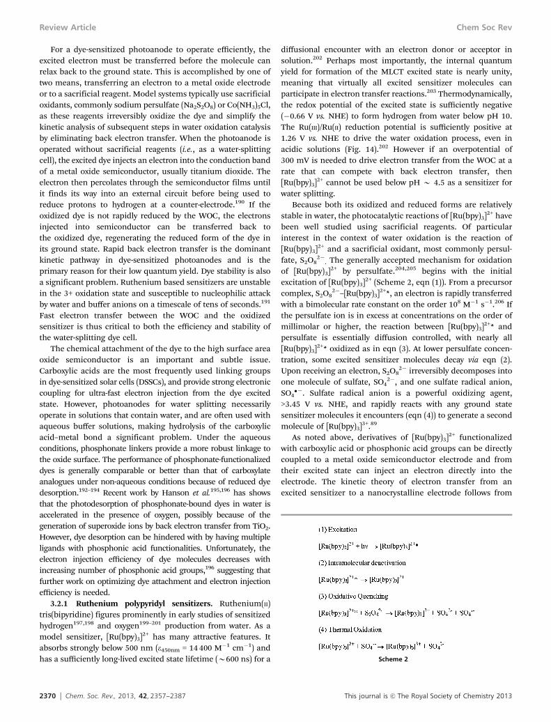
of [Ru(bpy)3]2+ by persulfate.204,205 begins with the initialexcitation of [Ru(bpy)3]2+ (Scheme 2, eqn (1)). From a precursorcomplex, S2O8
2�–[Ru(bpy)3]2+*, an electron is rapidly transferredwith a bimolecular rate constant on the order 108 M�1 s�1.206 Ifthe persulfate ion is in excess at concentrations on the order ofmillimolar or higher, the reaction between [Ru(bpy)3]2+* andpersulfate is essentially diffusion controlled, with nearly all[Ru(bpy)3]2+* oxidized as in eqn (3). At lower persulfate concen-tration, some excited sensitizer molecules decay via eqn (2).Upon receiving an electron, S2O8
2� irreversibly decomposes intoone molecule of sulfate, SO4
2�, and one sulfate radical anion,SO4
��. Sulfate radical anion is a powerful oxidizing agent,>3.45 V vs. NHE, and rapidly reacts with any ground statesensitizer molecules it encounters (eqn (4)) to generate a secondmolecule of [Ru(bpy)3]3+.89
As noted above, derivatives of [Ru(bpy)3]2+ functionalizedwith carboxylic acid or phosphonic acid groups can be directlycoupled to a metal oxide semiconductor electrode and fromtheir excited state can inject an electron directly into theelectrode. The kinetic theory of electron transfer from anexcited sensitizer to a nanocrystalline electrode follows from
Scheme 2
Review Article Chem Soc Rev

This journal is c The Royal Society of Chemistry 2013 Chem. Soc. Rev., 2013, 42, 2357--2387 2371
semi-classical Marcus theory and has been reviewed indetail.207,208 Using the Franck–Condon principle that nuclearcoordinates do not change during electron transfer, a distributionof donor energy states for the excited sensitizer molecule can becalculated. The width of this distribution depends on the freeenergy of the excited state as well as the reorganization energyrequired for the change in oxidation state of the sensitizer. Forreorganization energies between 0.3 and 0.8 eV the width ofdistribution is approximately equal to the reorganization energy,and for larger reorganization energies, the width of the distributionis less. If the width of the donor distribution is equal to thereorganization energy then the maximum rate of electron transferoccurs when the free energy of an electron in the semiconductorconduction band (Gc) is lower than or equal to the free energy of theground state (Go) plus the difference in free energy between theground and excited states (G00) minus twice the reorganizationenergy (l) (eqn (2)).
Gc r Go + G00 � 2l (2)
Eqn (2) describes the situation shown on the left in Fig. 12where the entirety of the distribution of donor states lies abovethe conduction band edge potential. When considering realsensitizers, this means that the maximum rate of electrontransfer will occur when the quantity, �(Go + G00 � 2l) nF�1,is more negative than the conduction band edge potential ofthe electrode. For [Ru(bpy)3]2+, the potential of the excited state,�(Go + G00) nF�1, is �0.84 V vs. NHE and the reorganizationenergy for the excited state is approximately 0.35 eV.209 Usingthese values, the maximum rate of electron injection into TiO2
will occur when the potential of the conduction band edge ismore positive than �0.14 V vs. NHE. The conduction band edgepotential of anatase TiO2 is 0 V vs. NHE at pH = 0 but decreasesby 55 mV per pH unit. Thus it is expected that at low pH there is asignificant overlap between unoccupied states in the conductionband and the distribution of donor states in the excited sensitizer.As the pH increases, the overlap decreases as the potential ofthe conduction edge band becomes more negative than�0.14 V
vs. NHE and the rate of electron transfer falls off (Fig. 12). Inthe case of TiO2, this model is insufficient to explain theexperimental behavior. As we shall discuss in the photoanodesection, the high density of conduction band states allows forinjection from excited states higher in energy than the lowestMLCT excited state.
One attractive quality of ruthenium tris(bipyridyl) deriva-tives and related complexes is the possibility of includingmultiple functionalities into the three ligands. In addition tophosphonic and carboxylic acid attachment functionalities,192–194
bipyridine ligands can be modified to act as linkage unitsto catalysts. Hoertz et al. functionalized 2,20-bipyridine with dicar-boxylic acid units in the 4,40 positions.157 These dicarboxylic acidgroups were used as capping agents for the controlled hydrolysis ofIrCl6
2� to form IrOx�nH2O with sensitizers directly coupled to theWOC particle. In an extension of that work, Youngblood et al.prepared a sensitizer containing a malonic acid functionality,which was used to cap an IrOx�nH2O nanoparticle, as well as a4,40-diphosphonic-2,20-bipyridine ligand for attachment to thenanocrystalline electrode (Fig. 13).67
Beyond attachment functionality, ligand modification canbe used to tune the redox and spectroscopic properties of thesensitizer.210,211 The lowest excited state of a rutheniumtris(bipyridyl) sensitizer, RuIIL3, is best described in termsof a ligand-localized state, RuIIIL2(L�). Because the electronlocalizes on one bipyridine ligand, the excited state ofthe sensitizer mirrors the electrochemical and spectroscopicproperties of the free reduced ligand. Upon excitation, theexcited electron hops rapidly (o15 ps)212 between ligandsand thermally equilibrates to reside primarily on the mostreadily reduced, that is the most electron-deficient, ligand.The excited state oxidation potential can be made more positiveby adding an electron-deficient ligand or more negative byadding electron-rich ligands.210 By using a combination ofs-donor and p-acceptor effects, the ground state oxidationpotential can also be shifted. Broadly considered, a moreelectron-deficient ligand donates less electron density vias-donation giving a higher nuclear charge on the metal centerand as a consequence, stabilizing the dp orbitals. Back-bondingbetween the dp and p* orbitals of the ligands results in furtherstabilization of the dp orbitals. The net effect is that complexeswith ligands that are more readily reduced exhibit more positiveoxidation potentials.189,213 In the context of water-splitting, electroninjection into a semiconductor electrode can be accelerated bymaking the ligand bound to the electrode the most electron-withdrawing. Along the same lines, an increased reductionpotential to drive a WOC can be generated by using more easilyreduced ligands. Of course, this strategy also leads to morepositive excited state potentials, which can affect the efficiencyof electron injection.
Multinuclear dendrimer sensitizers present an interestingpathway towards enhanced light harvesting in water-splittingdye cells. By coupling multiple photoactive metal centers,dendritic sensitizers show both extended and increased absorp-tion in the visible region relative to mononuclear sensitizers.Through careful selection of the core and branching metal ions
Fig. 12 Diagram of donor distribution functions, Wdon(G), and the density ofstates within the semiconductor electrode, D(E) at (a) low pH and (b) high pH.Reprinted with permission from ref. 183. Copyright 2005 American ChemicalSociety.
Chem Soc Rev Review Article

2372 Chem. Soc. Rev., 2013, 42, 2357--2387 This journal is c The Royal Society of Chemistry 2013
and ligands, a directed energy cascade reminiscent of photo-synthesis can be designed.214,215 Recently the tetrarutheniumsensitizer, [Ru{(m-dpp)Ru(bpy)2}3](PF6)8 (dpp = -2,30-bis(20-pyridyl)-pyrazine) was shown to drive water oxidation under sacrificialconditions.216,217 Notably, this complex drove water oxidationunder illumination with light >700 nm using IrOx�nH2O as theWOC. Extended light absorption comes with a price, namely thatthe excited state redox potential is roughly 0.4 V vs. NHE (Fig. 14)limiting the use of this complex to sacrificial systems. In principle,such a sensitizer could function at a water-splitting photoanode
using a semiconductor such as SnO2 or In2O3, which have morepositive conduction band edge potentials than TiO2.218
3.2.2 Porphyrin sensitizers. Poprhyrins and related macro-cyclic chromophores have been studied as sensitizers for watersplitting reactions for nearly three decades.222,223 Porphyrins arestrongly absorbing with intense Soret bands (e B 105 M�1 cm�1)in the blue part of the visible spectrum and Q-bands (e B 104)in the green to red.224 In recent years attention has returned tohigh potential porphyrins as sensitizers for both DSSCsand water-splitting photoanodes. A malonate substituted
Fig. 13 Structure of [Ru(bpy)3]2+ (Left), [Ru(dcbpy)(bpy)2]2+ (Middle), and [Ru(dpbpy)]2+ (Right).
Fig. 14 Plot of ground state, singlet, and triplet redox potentials versus the conduction and valence bands of TiO2. The difference in water oxidation potential at pH 0and 7 is shown. 1. [Ru(bpy)3]2+ (bpy = 2,20-bipyridine);186,196,211 2. [Ru(dcbpy)(bpy)2]2+ (dcbpy = 4,4 0-dicarboxy-2,20-bipyridine);219 3. [Ru(dpbpy)3]2+ (dpbpy =4,4 0-diphosphonic-2,2 0-bipyridine);196 4. Ru[{(m-dpp)Ru(bpy)2}3]8+ (dpp = -2,30-bis(20-pyridyl)pyrazine)220 5. ZnBPFP (BPFP = 5-(4-carbomethoxyphenyl)-15-(4-carboxy-phenyl)-10,20-bis-(pentafluorophenyl)porphyrin).221 †Singlet–triplet state splitting estimated via the method of Vlcek et al.211
Review Article Chem Soc Rev

This journal is c The Royal Society of Chemistry 2013 Chem. Soc. Rev., 2013, 42, 2357--2387 2373
5,10,15,20-tetrakis(4-bromomethylphenyl)porphyrin was usedto cap IrOx�nH2O nanoparticles.225 The porphyrin-cappedparticles demonstrated strong electronic coupling and sustainedcatalytic activity when poised at a potential of 1.4 V vs. Ag/AgCl.Moore et al. demonstrated visible light water-splitting via theco-deposition of a high potential porphyrin zinc 5-(4-carbo-methoxyphenyl)-15-(4-carboxyphenyl)-10,20-bis-(pentafluorophenyl)-porphyrin (ZnBPFP) and a Cp* iridium WOC onto a TiO2
electrode.98 A subsequent study considered photoanodes preparedfrom ZnBFPP as well as the free base version and palladiumanalogue.221 While no water oxidation catalyst was present, eachporphyrin demonstrated sufficient oxidizing potential for wateroxidation, however, only ZnBFPP had an excited state sufficientlynegative to inject an electron into the TiO2 anode (Fig. 15).
3.2.3 Sensitizer–catalyst dyads. Direct coupling of thesensitizer and WOC should lead to faster electron transfer ratesand in principle to higher overall efficiency. As noted above, Young-blood et al.67 coupled a ruthenium sensitizer directly to an IrOx�xH2O nanoparticle. Unfortunately, rapid quenching of the excitedstate by IrOx�xH2O limited any gains from faster electron transfer.Since the publication of that work several groups have adopted acoupled sensitizer–catalyst dyad strategy to address this problem.
Kaveevivitchai and co-workers coupled a ruthenium poly-pyridyl sensitizer to a single-site ruthenium WOC (Fig. 16).226
Under photochemical conditions with S2O82� as sacrificial
electron acceptor they observed a TOF of B0.005 s�1 and aTON of 134 over six hours. While low, the TON for theuncoupled system at higher concentrations was only 6. Further-more, the [Ru(bpy)2(pynap)]2+ (pynap = 2-(pyrid-20-yl)-1,8-napthyridine) sensitizer upon which the dyad is based wasshown to be an ineffective sensitizer.
A similar system built around a single site [RuL(pic)2] (L = 6,60-dicarboxy-2,20-bipyridine; pic = 4-picoline) complex was introducedby Li et al.227 This system coupled a modified ruthenium trisbipyr-idine sensitizer through each picoline ligand. As above, underphotochemical conditions, a significantly higher TON was observedfor the coupled system than for the analogous uncoupledsystem, 38 vs. 8 turnovers.
Ashford and coworkers introduced a general approach forcoupling chromophores and molecular WOCs.228 Via an amidelinkage formed at elevated temperatures, they coupled anamine functionalized ruthenium trisbipyridyl sensitizer to asingle site, ruthenium terpyridyl catalyst. Although they did notreport photochemical water oxidation, electrochemical andchemical water oxidation was found with oxygen yields ofB70% relative to initial Ce(IV) concentrations. Transientspectroscopy showed rapid intrassembly energy transfer. Thisfollowed work by the same group on coupled a sensitizer–catalyst dyad absorbed on a TiO2 electrode.229 Rapid injectioninto TiO2 and electron transfer from the catalyst to the sensi-tizer were observed. Back electron transfer to the oxidizedcatalyst was observed on the microsecond time scale. Injectionyields into TiO2 were low, possibly due to unfavorable ener-getics. Steady state photolysis data was not reported, butelectrochemical water oxidation current was observed.
Ultrafast flash photolysis studies of perylene derivativescoupled to a Cp* molecular Ir WOC revealed ultrafast electrontransfer (o10 ps) from the WOC to the excited perlyene.230
Unfortunately back electron transfer was also rapid andoccurred within several nanoseconds. While photocatalyticactivity was not observed due to the short charge separationlifetime, catalytic activity was retained and demonstratedelectrochemically.
3.3 Electron transfer mediators
The photochemical systems we have described thus far gener-ally involve a direct electron transfer between an oxidizedsensitizer molecule and the WOC. As noted above, direct
Fig. 15 Zinc 5-(4-carbomethoxyphenyl)-15-(4-carboxyphenyl)-10,20-bis-(penta-fluorophenyl)porphyrin (ZnBPFP).
Fig. 16 Photochemical water oxidation by a ruthenium bipyridyl sensitizer (red) coupled to a single site ruthenium WOC (black) through a 2,6-di-(1 0 ,80-napthyrid-20-yl)pyrazine (blue). Reprinted with permission from ref. 226. Copyright 2012 American Chemical Society.
Chem Soc Rev Review Article

2374 Chem. Soc. Rev., 2013, 42, 2357--2387 This journal is c The Royal Society of Chemistry 2013
electron transfer between P680+ and the OEC does not occur inphotosystem II, instead the tyrosine–histidine mediatorbetween them is an essential component of the electron trans-port chain. The mediator couples the fast electron transfernecessary to regenerate P680+ with the slower electron transferfrom the OEC. By analogy, incorporating a mediator between anoxidized, unstable sensitizer and WOC is a promising strategyfor use in a water-splitting DSSC.
Use of mediators in artificial photosynthesis has been pre-saged for some time. Molecular triads used in electron transferstudies represent the early examples of mediator-like systems.The initial example featured a carotenoporphyrin–quinonetriad which underwent rapid (o100 ps) initial charge separa-tion to yield a long-lived charge separated state (t1/2 = 170 ns).231
In the context of water splitting, triads have been designed toclosely mimic some of the structural and functional features ofphotosystem II. Johansson et al. prepared triads containing a[Ru(bpy)3]2+ core, a tyrosine ethyl ester, and a variety of electronacceptors.232 They observed a charge separation yield of B10%with a fraction of the charge separated states persisting formicroseconds. Extending the triad concept to a tyrosine-mod-ified ruthenium trisbipyridyl complex adsorbed to the nano-crystalline TiO2 film, Pan et al. noted ultrafast electroninjection into the TiO2 and B90% internal quantum yield fortransfer of an electron from the tyrosine.233 A multiexponentialcharge recombination process was observed with a componenton the millisecond time scale.
Though it was not used to drive photochemical water split-ting, a molecular triad containing a high potential porphyrinbearing two pentafluorophenyl groups demonstrated a chargeseparated state that was thermodynamically capable of wateroxidation.234 This triad featured a benzimidazole–phenol (BiP)electron donor, which mimics the tyrosine–histidine mediatorfound in the OEC. Unlike most phenols, which undergoirreversible oxidation, hydrogen bonding between the histidinein BiP and the phenolic proton allows for the proton to beshuttled upon oxidation of the phenol.235 An ionizable protoncontrols the electrochemical potential of the mediator, with thepotential 1.19 V vs. SCE in acidic conditions and 0.21 V vs. SCEunder basic conditions (Fig. 17).236
Recently Zhao et al. coupled the BiP mediator to an IrOx�nH2O colloid and co-absorbed a ruthenium polypyridine
sensitizer onto a TiO2 electrode (Fig. 18).237 With the mediator-capped catalyst, substantially higher and sustained photocurrentwas measured compared to mediator free catalyst. It is impor-tant to note that in this system there was no direct linkagebetween the sensitizer and the mediator, which were separatelyadsorbed onto the high surface area TiO2 electrode. The kineticsof bleaching recovery of the sensitizer, studied by nanosecondflash photolysis, were multi-exponential as expected for a kine-tically complex system with a range of distances between theelectron donor and acceptor. Using a Pt collector electrode, theyverified that the Faradaic efficiency (percentage of charge passedconverted to oxygen) was close to unity, i.e., that the observedphotocurrent corresponded to water oxidation.
As an alternative to using tyrosine derived mediators, theMeyer group has focused on the use of ruthenium polypyridylsas electron transfer mediators. The rate limiting step in Ce(IV)driven catalytic water oxidation by the blue dimer is oxidationof a RuIVQO to RuV or oxidation of terminal peroxido groupRuIV–OOH to give oxygen. In either case, the these steps arerate-limiting due to slow Ce(IV) electron transfer. Rutheniumpolypyridyls, for example [Ru(bpy)3]2+ or Ru(bpy)2(bpm)]2+, canbe added to function as redox mediators, undergoing rapidoxidation by Ce(IV) and increasing the rate of water oxidation by30-fold in the case of or Ru(bpy)2(bpm)]2+.238 To extend this workto electrochemical systems, they adsorbed [Ru(bmpbpy)2(bpy)]2+
(bmbpy = 4,40-bis-(methyl)phosphonato-2,20-bipyridine) onto anITO electrode and left the blue dimer in solution. Withoutsurface modification, a 3e�/3H+ oxidation wave correspondingto oxidation of RuIV–OH and RuIII–OH2 to RuVQO is not present.When the surface is modified by [Ru(bmpbpy)2(bpy)]2+, this waveappears. Sustained electrocatalysis at 1.46 V vs. NHE resulted in17 500 turnovers of [Ru(bmpbpy)2(bpy)]2+ and 1.25 turnovers ofthe blue dimer at a Faradaic efficiency of 95%. Higher turnoversof the blue dimer were limited by precipitation of the catalystonto the electrode surface.239 The issue of catalyst precipitation
Fig. 17 Benzimidazole–phenol (BiP) mediator at neutral conditions (1), basicconditions (3), and acidic conditions (4). Also shown is a methoxy derivative (2)that does not undergo reversible oxidation. Reprinted with permission fromref. 236. Copyright 2010 American Chemical Society.
Fig. 18 Electron transfer reactions of mediator-decorated iridium oxide and dyesensitized TiO2 anode. Reprinted with permission from ref. 237.
Review Article Chem Soc Rev

This journal is c The Royal Society of Chemistry 2013 Chem. Soc. Rev., 2013, 42, 2357--2387 2375
was circumvented by preparing a single site ruthenium catalystdirectly coupled to the phosphonate-modified electron transfermediator through a 2,20-bipyrimidine. When attached to an ITOelectrode held at 1.8 V vs. NHE, more than 28 000 turnoverscould be observed with a TOF of 0.6 s�1 and no loss of catalyticactivity (Fig. 19). On a nanocrystalline TiO2 electrode, a Faradaicefficiency of 98% for oxygen production was obtained.240
3.4 Photoanode materials
The anode in a dye-sensitized solar cell serves two majorfunctions, to facilitate light absorption and effectively collectelectrons. Efficient light absorption with ruthenium-basedsensitizers requires electrodes with surface areas hundreds oftimes greater than the geometric area of the cell. Also, theframework that supports the sensitizer must be transparent inthe visible region. The most common photoanode in dye cells isa mesoporous film of sintered TiO2 nanocrystals prepared ontop of a transparent conducting oxide (TCO) such as fluorinedoped tin oxide. A secondary benefit is that the high surfacearea structure relaxes the minimum TOF required for the WOCin full sun. As noted above, the minimum TOF for a catalystadsorbed on a high surface area electrode is on the order ofB3 s�1 nm�2.
Once a reasonably high fraction of the light can be absorbedand utilized, electron collection becomes critical. An efficientphotoanode must accept an electron rapidly from the excitedstate of the sensitizer before intramolecular relaxation canoccur. Once injected, the electron should rapidly move throughthe film until it reaches the TCO. The collection efficiency is ameasure of how effectively the semiconductor film transportselectrons, and is defined as the fraction of injected electronsthat exit the photoanode to the external circuit. Electrongeneration, diffusion, and interception govern the collection
efficiency, which can be described by the continuity equation:
@n
@t¼ ZinjI0ae
�ax þDn@2n
@x2� nðxÞ
tn¼ 0 (3)
Here n, Zinj, I0, a, and Dn are the free electron concentration inthe film, charge injection efficiency, photon flux, absorptioncoefficient of the film, and apparent diffusion coefficient,respectively. tn is the free electron lifetime and in a DSSCdescribes the rate of interception by triiodide electron acceptorsin the electrolyte. If boundary conditions are applied, the currentat a given voltage can be found by solving steady-state equationfor a film of thickness x. Generally this equation shows thatmaximizing any of those values can increase efficiency in aDSSC. As we discussed in the section on sensitizers, injectionefficiency (Zinj) is a function of the overlap of excited donor stateson the molecule and density of states on the semiconductor. Thephoton flux and absorption coefficient are controlled by trans-parency of the semiconductor framework and the concentrationof the sensitizer within the film. Theoretically, the apparentdiffusion coefficient is dependent upon the mobility of theelectron within the semiconductor. Likewise, tn should onlydepend on electron density under illumination and by extensionthe Fermi level of the electrons in the film. As we shall discuss,both parameters are controlled by charge trapping (Fig. 20).
Trap states play a significant role in controlling the apparentdiffusion coefficient and lifetime of electrons in the semiconductorfilm. Electrons are initially injected from the excited sensitizer tothe conduction band of the TiO2 electrode. Once in the conductionband, the electrons rapidly relax into an exponential distribution ofband gap trap states.241,242 Energetically deep trap states lie farbelow the conduction band and result in electrolyte recombinationin the DSSC, determining tn.243 Shallow trap states provide thedominant pathway for charge transport in nanocrystalline TiO2
films.244 Electrons hop from trap to trap in a thermally activated
Fig. 19 (Left) Combination electron transfer mediator (green) and water oxidation catalyst (red) [(bmpbpy)2RuII(bpm)-RuII(tpy)(OH2)]4+ absorbed to ITO electrode.(Right) Electrolysis at 1.8 V vs. NHE in 1.0 M HClO4, B28 000 turnovers, 0.6 s�1. Reprinted with permission from ref. 240. Copyright 2009 Wiley-VCH Verlag Gmbh & Co.
Chem Soc Rev Review Article

2376 Chem. Soc. Rev., 2013, 42, 2357--2387 This journal is c The Royal Society of Chemistry 2013
process described by a continuous random walk model.Because the process is thermally activated the probability ofan electron hopping from a trap state depends on the depth ofthe trap.245 Transport through a nanocrystalline film involvesB107 trapping/detrapping events.246 The apparent diffusioncoefficient, Dn, depends heavily on the density and depth oftrap states.247 Biasing the electrode in the forward direction, i.e.shifting the potential towards the open circuit value, raises theFermi level of the electrons in the film and fills the deeper trapsbefore filling the shallower traps (Fig. 21).244
Applying the above analysis to oxygen-evolving dye-sensi-tized photoanodes is not straightforward. Little work has beendone to understand the dynamic processes that limit collectionefficiencies in such cells, although some analogies can bedrawn. In DSSCs, regeneration of the oxidized sensitizer by I�
(or other donors such as Co2+ complexes248,249) is fast so themajor recombination pathway is with the oxidized donor inthe electrolyte. In contrast, water is a slow electron donor atoxygen-evolving photoanodes and electron scavenging byphotogenerated oxygen is not a major kinetic pathway. Instead,the recombination kinetics are dominated by back electrontransfer to oxidized sensitizer molecules at the TiO2/solutioninterface, and this process is about one order of magnitudefaster than electron transfer from the catalyst to the oxidizedsensitizer.67,250 It is likely that deep traps favor recombinationrelative to current collection as they do in conventional DSSCs,but the details are unknown at this time. The recombinationkinetics are non-exponential, implying multiple processes with
multiple activation energies.193,251 This suggests that recombi-nation involves a range of trap states, but further work isneeded to better understand this process.
In the following sections we will discuss three oxide semi-conductors, TiO2, SnO2, and ZnO, which have been well studiedin DSSCs and how they apply to oxygen-evolving photoanodes.We will also discuss electrode-related routes to increase overallefficiency.
3.4.1 TiO2 electrodes. To date, all water-splitting dyecells have been based upon nanocrystalline TiO2. This is notsurprising as TiO2 was the first photoanode material used inDSSCs and remains the most common today. Titania has threecommon crystal polymorphs, rutile, anatase, and brookite.252
Phase pure brookite is difficult to obtain and is the leaststudied of the three. Rutile is composed of TiO6 octahedra thatshare opposite edges to form linear chains along the [001]direction. These chains are connected by three-coordinateoxygen atoms to make the three-dimensional lattice. In DSSCs,anatase is typically the crystal polymorph of choice. The majorreasons for the use of anatase are its superior electron transportproperties relative to rutile and its conduction band edgepotential, which is B200 mV more negative than rutile. Anatasealso has a slightly more open structure than rutile because theTiO6 octahedra share only four edges, leading to higher dyeloading.252
Electron transport in TiO2 takes place in surface mid-bandgap trap states.253 Under-coordinated Ti3+ centers on the(001) and possibly (101) surfaces of the nanoparticles arethought to be responsible for these trap states.254 As a result ofthese surface trap states, diffusion coefficients of nanocrystallineTiO2 electrodes are roughly 3 orders of magnitude lower than insingle crystal anatase.255,256 Lattice mismatches at grain boundariescan also create diffusion limiting trap states.257
Compared to other nanocrystalline oxide semiconductors,electron injection into TiO2 is unusually fast (o100 fs) in theDSSC. As we discussed in sensitizer section, classical electrontransfer theory states that an electron from the sensitizer istransferred from a distribution of donor states below theexcited state redox potential. In this model, electron injectionshould not be possible when the excited state potential of thedye lies below the conduction band edge. Experimental studiesby Asbury et al. demonstrate that sensitizers with excited statepotentials below the conduction band edge of TiO2 are able toinject electrons into the semiconductor.179,182 Their results
Fig. 20 Effect of Fermi level on trap filling.
Fig. 21 Trapping/detrapping transport through semiconductor.
Review Article Chem Soc Rev

This journal is c The Royal Society of Chemistry 2013 Chem. Soc. Rev., 2013, 42, 2357--2387 2377
show that electron injection occurs from a vibrationally hotstate, i.e. an excited molecule that has not relaxed to the bottomof the 3MLCT state, into a high density of conduction bandstates. This behavior is not observed with ZnO or SnO2 and itwas postulated that differences in the conduction band densityof states could explain this behavior. The conduction band inTiO2 is formed from empty 3d orbitals, whereas in ZnO andSnO2 the conduction bands are respectively comprised of 4sand 5s/5p orbitals.
Ultrafast injection kinetics of TiO2 could be utilized forhigher efficiency water splitting cells. Charge injection in theDSSC only needs to be fast compared to dye relaxation. Inanatase, charge injection is typically 3 orders of magnitudefaster than relaxation,258 and this provides some designflexibility to engineer slower recombination rates. Thin metaloxide blocking layers, such as Al2O3,259 Nb2O5,260 ZrO2,
261 MgO,and Y2O3,262 can be inserted between the sensitizer and theTiO2 to increase the physical separation and passivate surfacetraps. At an uncoated TiO2 electrode, recombination can occurdirectly from trap states at the surface or via thermal detrap-ping from interior trap states.190,251,263 With the surface statespassivated, recombination can only occur from interior trapstates, which must undergo thermal detrapping into the con-duction band. The recombination kinetics are roughly a factorof three slower and dominated by the rate of tunneling fromthe conduction band through the barrier (Fig. 22).264 Chargeinjection through the barrier is also slowed, but as long as thebarrier layers are thin, unit injection yields are still observedbecause the rate can slowed by two orders of magnitude andstill be fast compared to relaxation. Lee et al. introduced theblocking layer strategy for oxygen-evolving photoanodes bycoating a TiO2 electrode with 1–2 nm thick layers of ZrO2 orNb2O5. Tests in a DSSC configuration showed injection yieldsremained high with 1–2 nm thick coatings but fell off as thecoating thickness increased. With the introduction of theblocking layer, the recombination rate slows by a factor of2–3 and a fast component of charge recombination disappears.
Photoelectrochemical tests with the Nb2O5 coated electrodesshowed higher peak and sustained photocurrent when com-pared to the bare TiO2 and a Faradic efficiency of B100%for oxygen evolution.265 These results strongly suggest thatblocking layers are a promising avenue for improvement.However, more studies both on layer composition and thicknessare needed to deliver on this promise.
As we noted earlier, diffusion in nanocrystalline films is slowcompared to single crystals. Besides surface trap states, grainboundaries between particles contribute to poor diffusion inconventional TiO2 nanocrystalline films. In principle, eliminatingor minimizing grain boundaries should lead to enhanceddiffusion and increased carrier lifetime. One-dimensionalnanostructures offer moderately high surface area for lightharvesting, while eliminating deleterious interparticle connec-tions. Electrodes prepared from films266–268 and oriented arraysof TiO2
269–274 nanotubes and nanowires have received a greatdeal of attention as a method for improving electron transport.Generally speaking, the charge collection efficiencies in thesegeometries are somewhat higher than with nanoparticulateelectrodes. For nanotubes, this is more a function of slowrecombination as transport times versus nanoparticle electrodesare roughly the same, possibly due to similarities in crystallitesize.270,275 Feng et al. recently reported that crystalline rutilenanowires also show slow recombination and exhibit a diffusioncoefficient B200 times higher than polycrystalline rutilefilms.276 TiO2 coated nanotubes of indium tin oxide (ITO) grownwithin the pores of a high surface area membrane demonstratedenhanced current density due to efficient radial collection ofelectrons by the conductive ITO layer.277 At this time, noexamples of dye-sensitized water splitting cells exploiting 1-Delectrode morphologies have been published.
Introduction of dopants into the TiO2 crystal structurerepresents a third significant avenue towards improved electrontransport. A rapidly growing list of dopants added to TiO2 inDSSCs include cations Li+,278 Nb5+,279,280 Ta5+,281 Zn2+,282 Al3+,283
Mg2+,284 W6+,285 Ga3+, B3+,286 and Y3+,287 as well as the N3�
anion288 and B3+/N3�co-dopants.289 Despite the wide variety ofdopants, several points are common across the various reports.First, high dopant levels generally lead to degradation in thedevice performance. Second, charge collection is generallyenhanced by a suppression of recombination rates. Third,conduction band potentials shift, while valence band potentialsare unaffected. Fourth, electron transport and diffusion rates aregenerally slowed. An interesting exception to this rule is Zn2+,which shows faster transit times through the film. The authorsposit that the intrinsically high donor density of Zn2+ leads tofewer unfilled trap states and increased electron mobility.282
Theoretical work on the effect of dopants has been undertaken.Morgan et al. considered Nb- and Ta-doped TiO2
290 and observedthat both dopants created similar small polarons localized onTi3+ sites, leading to similar performance. This agrees with theconclusions of Dy et al.291 who reported that addition of tantalumand niobium shifted the Fermi level towards otherwiseunoccupied conduction band states. By contrast, rutheniumdoping created mid-gap states and only slightly shifted the
Fig. 22 Recombination of an injected electron to the oxidized sensitizer with-out a blocking layer (Left) and with a blocking layer (Right). Red arrows denoterecombination from surface trap states.
Chem Soc Rev Review Article

2378 Chem. Soc. Rev., 2013, 42, 2357--2387 This journal is c The Royal Society of Chemistry 2013
Fermi level. The model suggests that ruthenium does notincorporate readily into anatase so that the mid-bandgap statesare a result of formation of new electronic states within thematerial. Tantalum, and to a lesser extent niobium, readilyincorporate into the lattice and perturb largely surface states.An important caveat is that this work has been done entirely inthe context of DSSCs, where recombination with the triiodide isthe main challenge. To the best of our knowledge, doped-TiO2
has not been considered in the context of dye-sensitized watersplitting cells.
3.4.2 SnO2 electrodes. As noted above in the context ofdendrimer based sensitizers, increasing utilization of the solarspectrum while maintaining sufficient oxidizing power to drivewater oxidation results in excited state redox potentials that aretoo positive for electron injection into TiO2. Substituting asemiconductor with a more positive conduction band potentialfor TiO2 would allow for the use of less reducing dyes. Whilethis would reduce the photovoltage of the cell, it would alsolower the driving force for back electron transfer and possiblyslow the rate of that process. The conduction band edge ofrutile SnO2 is B500 mV more positive than that of anataseTiO2. Bergeron et al. have demonstrated the viability of thisapproach using ruthenium sensitizers on SnO2 with excitedstate potentials too positive for electron injection into TiO2.292
Numerous examples of SnO2-based DSSCs appear in theliterature.293–299 Generally, unmodified SnO2 DSSCs exhibitpoor solar cell characteristics compared to TiO2: lower opencircuit voltage, lower current density, and poorer fill factors.Kay and Gratzel demonstrated that better performing SnO2
electrodes could be made by adding a thin insulating shell.They attributed the improvement to enhanced dye loading andinhibition of back electron transfer to I3
�.262 SnO2 has higherelectrical conductivity300 and mobility301 than TiO2, but thehigher electron mobility of SnO2 was recognized by Green et al.as a contributor to its poor performance in DSSCs.302 Like TiO2,electron transport in SnO2 is controlled by thermal trapping/detrapping. Unlike TiO2, however, the density of trap states inSnO2 is significantly lower, resulting in an electron diffusioncoefficient 2 orders of magnitude greater than in TiO2. The rateof electron transport in SnO2 is rapid enough that in DSSCs itcompetes with the fast reduction of the oxidized sensitizerby I�. SnO2 also exhibits slower injection dynamics whencompared to TiO2.188 Ai et al. suggested this difference maybe due to differences in the conduction band densities of statesof the two semiconductors. In TiO2 the conduction band isprimarily composed of relatively localized d-orbitals, which givea narrow distribution of states of much higher density than thesp-orbital conduction band of SnO2.303
3.4.3 ZnO core–shell electrodes. Although the bandgapand conduction band edge potential of ZnO are similar tothose of TiO2,304 the carrier lifetime in ZnO is higher.305
Electron diffusivity in crystalline ZnO nanowires is hundredsof times faster than in TiO2 nanoparticle films.306 Despite thesedesirable properties, ZnO is not likely to be a good photoanodefor water splitting cells because of its instability in acidicconditions.307 However, it may be possible to stabilize ZnO in
core–shell structures. ZnO nanowires coated with a TiO2 shellshowed a decrease in the recombination rate, which wasattributed to a radial surface field caused by the TiO2 coating.308
A similar strategy was used to coat a quasi-1D silica aerogel withcoaxial layers of ZnO and TiO2. Electron transport in the constructwas B2 orders of magnitude faster than in aerogels coated withonly TiO2, suggesting that the ZnO layer acts as a rapid conduit forelectron transport.309
3.5 System-level design
3.5.1 Overall cell efficiency. While water splitting DSSCsoperate with low quantum yield (2–3%) because of the fastkinetics of back electron transfer, it is important to considerhow they might function as energy conversion systems if thiskinetic problem could be solved. In a water splitting cellcontaining a single light absorber (e.g., [Ru(dpbpy)3]2+) sensitiz-ing a TiO2 anode, the maximum photovoltage or open circuitvoltage can be estimated from the potentials of the O2/H2Ocouple and the Fermi level of the semiconductor, which at lowtrap density and high levels of illumination should be close tothe conduction band potential. A common misconception isthat the photovoltage should be calculated as the differencebetween the Fermi level and the potential of the H2/H+ couple.The maximum photovoltage will be obtained when the cathodereaction is the reverse of the anode reaction, i.e., reduction ofoxygen. At a pH of 5.8 the thermodynamic potential for watersplitting is 0.89 V vs. NHE and the conduction band edge ofTiO2 is �0.54 V vs. NHE, meaning that the maximum photo-voltage that could be generated by the cell is 1.43 V. In practice,however, the open circuit voltage of the best dye-sensitizedphotoanodes is B1.0 V and a bias of several hundred mV isneeded to reach the maximum power point. This implies that asecond, complementary absorber should be added to thecathode side of the cell to provide additional photovoltage todrive overall water splitting. Connolly and coworkers performed adetailed analysis of the efficiency limits of solar water splitting.8
They determined that dual absorber ‘‘Z-schemes,’’ which like plantphotosynthesis use two photons per electron, are more forgivingthan single-absorber systems. If operated near unit quantumefficiency, photoelectrochemical Z-schemes could achieve overallefficiencies in the 10–15% range, assuming quantum yields nearunity and reasonable total losses (B700–800 mV) for seriesresistance and catalyst overpotentials.
Because dye-sensitized water splitting cells operate nearneutral pH in buffered aqueous solutions, Hernadez-Paganet al. considered the inherent potential losses in such systemswhen the anode and cathode separated by an ion exchangemembrane to facilitate separation of hydrogen and oxygen.310
They gave the total potential loss in the cell as:
E = Zanode + Zcathode + iRsol + EM + EpH (4)
where Zanode and Zcathode represent the overpotentials of theanode and cathode, iRsol is the resistance of the solution, EM
is the membrane resistance, and EpH is the potential lossassociated with the pH gradient. Resistance losses due tocharge transport through TiO2 are typically low and therefore
Review Article Chem Soc Rev

This journal is c The Royal Society of Chemistry 2013 Chem. Soc. Rev., 2013, 42, 2357--2387 2379
not considered. In acetate and phosphate buffers, overpotentiallosses were between 400–650 mV depending on the concen-tration of the buffer. This implies that the remaining potentiallosses in equation should be B200 mV or less to achievereasonably efficient water splitting. In concentrated buffers,the losses from solution resistance (iRsol) and membraneresistance (EM) were typically small, provided that the solutionpath length was kept short. However, the potential drop due tothe formation of a pH gradient across the membrane could beas large as several hundred millivolts at current densitiestypical of efficient photoelectrochemical cells.
The formation of the pH gradient could be understood byconsidering migration of buffer ions through the membrane.With an anionic membrane and phosphate buffer, the onlycharge carriers that can migrate through the membrane areHPO4
2� and H2PO4�. This process depletes the buffer on the
cathode side of the cell, where the reduction of protons causesthe pH to increase substantially there. In order for EpH toremain low, the diffusional flux of the neutral form of thebuffer, JD, must be equal and opposite to the migrational fluxof the charged form of the buffer, JM. With 200 mm thickmembranes, JM was much larger than JD leading to membranepolarization. The conclusion of the study was that thinner,more permeable membranes would need to be developed andused in conjunction with very concentrated buffers in order forphotoelectrochemical water splitting cells to operate efficiently.
3.5.2 Buffer selection. The choice of buffer can have asubstantial and largely uninvestigated effect on the efficiencyof water oxidation. Using a [Ru(bpy)3]2+–S2O8
2�–IrOx modelsystem, Hara et al. demonstrated a three-fold enhancement inthe TON for oxygen evolution when a Na2SiF6–NaHCO3 bufferwas used instead of KH2PO4–Na2B4O7 buffer.156 Slower decom-position of the oxidized sensitizer was suggested as the reasonfor improvement, but the authors conceded that the complexoverall decomposition pathway made it difficult to quantify thekinetics. An interesting observation is that phosphate deactiva-tion of metal oxide catalysts in other oxidation reactions is wellknown.311–314 Deactivation of surface sites by phosphateexchange315 as well as scavenging of hydroxyl radicals316 isgenerally accepted as the reason for decreased catalytic activity.More work is needed to elucidate the role that the buffer playsin catalysis and in the decomposition of sensitizer molecules.
The silicate buffer derived from Na2SiF6–NaHCO3 isunstable, decomposing to colloidal silica over a period of days.It is likely that the actual buffer in this system is an oligomericsilicate. The silicate buffer has been useful for testing manyWOCs under photocatalytic conditions, and a study by Morrisand Mallouk optimized the buffer composition and pH in the[Ru(bpy)3]2+–S2O8
2�–IrOx system by a factorial design-of-experimentmethod.317 In a photoelectrochemical cell however, this oligomericbuffer may be problematic because it may not be able to access allof the pore volume of the nanocrystalline TiO2 electrode. Inefficientbuffering may explain the anode polarization effect that has beenobserved in almost all water-splitting dye cell experiments to date.This is illustrated in Fig. 23, and is also evident in Fig. 19. When thecell is held at a potential at which water splitting can occur and the
light is switched on, the initial photocurrent is typically in therange of 0.2–0.3 mA cm�2, corresponding to a quantum yield(per absorbed photon) on the order of 20%. The steady statephotocurrent decays over tens of seconds, reaching a plateauthat is 10–20% of the initial value. The oxygen evolved can bequantified by using a dark Pt electrode near the photoanode.This experiment reveals that oxygen is produced with highcurrent efficiency during the photocurrent decay. Switchingthe light off for tens of seconds restores the initial photo-current, and this cycle can be repeated hundreds of times.There are two possible causes of this polarization effect. One isthat electron transfer between catalyst and oxidized sensitizerbecomes slower as the catalyst is oxidized, and the other is thatthe solution becomes locally more acidic because the wateroxidation reaction generates four protons per O2 molecule. Inthe latter case, the overpotential for catalytic water oxidation,and thus the catalytic rate, would decrease as the pH is drivendown by the reaction. Experiments with buffers that canpenetrate the pore volume of the TiO2 electrode are clearlyneeded to address this question and to minimize electrodepolarization.
3.5.3 Z-schemes. All of the photochemical and photo-electrochemical systems we have discussed to this point utilizea single absorber, and as noted above dual-absorber systemsare likely to be more effective in utilizing the solar spectrum todrive unassisted water splitting. However, for a two-absorbersystem to work efficiently, the photoredox levels of the two partsof the electron transport chain must be properly aligned(Fig. 24). The first oxidized absorber drives water oxidation,while the second reduced absorber drives water reduction. Bothabsorbers could both be on the same electrode or split to give aphotoanode and photocathode. In either configuration, twophotons are absorbed to generate one electron for waterreduction and one hole for water oxidation. As we noted earlier,this is the basic design of plant photosynthesis.
Z-schemes have been demonstrated with photocatalysts,318
but only with low (B1%) quantum yields. The kinetic optimiza-tion of Z-schemes is difficult because of the requirement forcurrent matching and because of the increased possibilities for
Fig. 23 Generator–collector measurements indicating polarization for a TiO2–dye–IrOx photoanode. The black trace corresponds to the photocurrent from theelectrode, while the red trace corresponds to current from the catalytic reductionof evolved oxygen. Reproduced from ref. 265 with permission from The RoyalSociety of Chemistry.
Chem Soc Rev Review Article

2380 Chem. Soc. Rev., 2013, 42, 2357--2387 This journal is c The Royal Society of Chemistry 2013
charge recombination in more complex photosystems.The concept is so far largely untested in dye-sensitized watersplitting cells. Fukuzumi and co-workers showed dual absorberbehavior with a photochemical system based on rutheniumsensitizers and BiVO4.319 Using [Co(NH3)5Cl]2+ as a sacrificialreagent, they demonstrated a five-fold enhancement of photo-chemical oxygen evolution with the addition of [Ru(bpy)3]2+.They speculated that [Ru(bpy)3]2+ was oxidized by the sacrificialcobalt complex and reduced via electron transfer of an electronfrom the conduction band of BiVO4. The thermodynamics ofthe system would support this conclusion, as the driving forcefor electron transfer to [Co(NH3)5Cl]2+ is much larger with[Ru(bpy)3]2+ than BiVO4 and [Ru(bpy)3]3+ is not sufficientlyoxidizing to drive water oxidation with BiVO4 as the catalyst.While this is an interesting proof of concept, the absorptionbands of [Ru(bpy)3]2+ and BiVO4 overlap and are confined to theblue part of the spectrum. Brillet et al. demonstrated a multipleabsorber water splitting cell using hematite as a photoanode inseries with two DSSCs to produce sufficiently high voltagefor water reduction.320 The photon to hydrogen conversionefficiency was low (B1.36%) due to poor light harvesting.
4. Conclusions
Water splitting using dye sensitized electrodes is a relativelynew area of research that has significant promise for thedevelopment of efficient solar fuel systems. Although thecurrent performance of these systems is very poor – with steadystate photocurrents corresponding to only 2–3% quantum yield invisible light – most of the problems with these cells are understoodand in principle addressable by using well-established principles ofelectron transfer kinetics and molecular design. At the photoanode,the key problem is to control the relative rates of forward and backelectron transfer at the sensitizer molecule. Because back electrontransfer occurs on the timescale of hundreds of microseconds, thesystem needs to be designed to regenerate the reduced sensitizeron the microsecond (or faster) timescale. Experiments with electrontransfer mediators (Fig. 18 and 19) are beginning to attack thisproblem. In this context, it should be possible to utilize some ofthe design principles of electron transfer supermolecules (dyads,triads, tetrads, etc.) that have been engineered to give long-lived
charge-separated states by controlling the distance betweenredox-active components.68 A related problem is to synthesizewater oxidation catalysts, preferably from abundant elements,that can be used in water-splitting photoanodes at modestoverpotentials. While the absolute requirement for these cata-lysts is a site turnover frequency on the order of 3 s�1, to keep upwith the flux of solar photons, in practice much faster turnover isneeded to compete with back electron transfer. The turnoverfrequencies of the best synthetic and colloidal WOCs are alreadyapproaching that of the OEC in photosystem II, which generatesoxygen in high quantum yield thanks to fast electron transferbetween the tyrosine–histidine mediator and P680+. It is notunreasonable to expect that synthetic systems could soon beengineered with similar kinetics and high quantum yields.
Beyond the photoanode, system-level problems need to beaddressed in order to achieve efficient photoelectrochemicalwater splitting. It seems clear that a two-absorber Z-scheme willbe needed in order to use the visible and near-infrared parts ofthe spectrum effectively. Placing one photosystem at the anodeand the other at the cathode, as shown in Fig. 4, avoids some ofthe possible short-circuiting reactions of colloidal Z-schemesand would allow for the use of two different sensitizers, perhapswith energy transfer cascades at the anode or cathode or both toimprove light harvesting. Along these lines, we were able toconstruct, using layer-by-layer assembly of polyelectrolytes andoxide semiconductor nanosheets, a porphyrin-based energy/electron transfer cascade that separated charge across a semi-conductor nanosheet.68 Although that system was not coupledto catalysts for hydrogen evolution, the viologen electronacceptor that was used is capable of reducing water to H2 atneutral pH. Subsequent experiments have shown that it ispossible to use light driven charge separation acrossnanosheets to generate H2 in high quantum yield in sacrificialsystems.321 The challenge is to construct systems like this onhigh surface area electrodes where the photogenerated holescan be carried away to the external circuit. Some progress hasrecently been made in synthesizing arrays of (ITO) nano-tubes,322 as well as high surface area porous ITO electrodes,323
which might be used for this purpose.Beyond the challenge of demonstrating an efficient water
splitting system at the proof-of-concept level using dye-sensi-tized electrodes, it will be important to engineer such systemsfor durability. In practical terms, this implies sensitizer andcatalyst TONs approaching 109. Photoredox molecules arenotoriously unstable in water at the potential of water oxidationand it is well known that even photosystem II is subject tooxidative damage on a timescale of tens of minutes in full sun.Two possible strategies for addressing this problem are repairand protection, both of which are used effectively in naturalphotosynthesis. In an engineered photoelectrochemical system, itis difficult to imagine such a repair mechanism, especially fororganic dyes and redox molecules that are degraded by reactiveoxygen species generated at the photoanode. However, protectionof the photoredox assembly, e.g., by encapsulation in silica, is astrategy that is already beginning to be explored for molecule–catalyst dyads.324
Fig. 24 Two absorber Z-scheme for overall water splitting.
Review Article Chem Soc Rev

This journal is c The Royal Society of Chemistry 2013 Chem. Soc. Rev., 2013, 42, 2357--2387 2381
Acknowledgements
We gratefully acknowledge the efforts of our Penn Statecoworkers in the water splitting project, Paul Hoertz, JustinYoungblood, Anna Lee, Yixin Zhao, Dongdong Qin, NellaVargas-Barbosa, Emil Hernadez-Pagan, Nina Kovtyukhova, NickMcCool, Timothy Saunders, Landy Blasdel, and Deanna Lentz,as well as our Arizona State collaborators Jackson Megiatto, AnaMoore, Tom Moore, and Devens Gust. This work was supportedby the Office of Basic Energy Sciences, Division of ChemicalSciences, Geosciences, and Energy Biosciences, Department ofEnergy under contract DE-FG02-07ER15911.
References
1 T. Lipman, An Overview of Hydrogen Production and StorageSystems with Renewable Hydrogen Case Studies, CleanEnergy States Alliance, Oakland, CA, 2011.
2 C. A. Grimes, O. K. Varghese and S. Ranjan, In Light, Water,Hydrogen: The Solar Generation of Hydrogen by Water Photo-lysis, Springer Science, New York, 1st edn, 2008, pp. 1–33.
3 L. Vernon, Fuel, 1980, 59, 102–106.4 R. B. Alley, Earth The Operators Manual, W.W. Norton & Co.,
New York, 2011, pp. 239–251.5 N. D. McDaniel and S. Bernhard, Dalton Trans., 2010, 39,
10021–10030.6 W. Shockley and H. J. Queisser, J. Appl. Phys., 1961, 32,
510–519.7 M. C. Hanna and A. J. Nozik, J. Appl. Phys., 2006,
100, 074510.8 J. R. Bolton, S. J. Strickler and J. S. Connolly, Nature, 1985,
316, 495–500.9 M. D. Archer and J. R. Bolton, J. Phys. Chem., 1990, 94,
8028–8036.10 H. D. Holland, Philos. Trans. R. Soc., B, 2006, 361, 903–915.11 M. Grabolle and H. Dau, Biochim. Biophys. Acta, 2005, 1708,
209–218.12 H. J. van Gorkom and R. de Wijn, Biochim. Biophys. Acta,
2002, 1553, 302–308.13 J. McEvoy and G. Brudvig, Chem. Rev., 2006, 106,
4455–4483.14 I. McConnell, G. Li and G. W. Brudvig, Chem. Biol., 2010,
17, 434–447.15 R. J. Pace, R. Stranger and S. Petrie, Dalton Trans, 2012, 41,
7179–7189.16 A. Melis, Plant Sci., 2009, 177, 272–280.17 X.-G. Zhu, S. P. Long and D. R. Ort, Annu. Rev. Plant Biol.,
2010, 61, 235–261.18 N. Nelson and C. F. Yocum, Annu. Rev. Plant Biol., 2006, 57,
521–565.19 C. Beadle and S. P. Long, Biomass, 1985, 8, 119–168.20 C. Beale and S. P. Long, Plant, Cell Environ., 1995, 18,
641–650.21 D. R. Ort and S. P. Long, in Plants, Genes, and Crop
Biotechnology, ed. M. Chrispeels and D. Sadvada, Jonesand Bartlett Publishers Internation, 2003, pp. 240–269.
22 H. Michel, Angew. Chem., Int. Ed., 2012, 51, 2516–2518.23 S. Elliott, K. S. Lackner, H. J. Ziock, M. K. Dubey,
H. P. Hanson, S. Barr, N. A. Ciszkowski and D. R. Blake,Geophys. Res. Lett., 2001, 28, 1235–1238.
24 X.-G. Zhu, S. P. Long and D. R. Ort, Curr. Opin. Biotechnol.,2008, 19, 153–159.
25 J. Zhao, A. Wang, M. A. Green and F. Ferrazza, Appl. Phys.Lett., 1998, 73, 1991.
26 F. E. Osterloh, Chem. Mater., 2008, 20, 35–54.27 G. Schrauzer and T. Guth, J. Am. Chem. Soc., 1977, 99,
7189–7193.28 K. Yamaguti and S. Sato, J. Chem. Soc., Faraday Trans. 1,
1985, 81, 1237–1247.29 A. Kudo, K. Ueda, H. Kato and I. Mikami, Catal. Lett., 1998,
53, 229–230.30 A. Kudo, K. Omori and H. Kato, J. Am. Chem. Soc., 1999,
121, 11459–11467.31 K. Maeda, K. Teramura, D. Lu, T. Takata, N. Saito, Y. Inoue
and K. Domen, Nature, 2006, 440, 295.32 K. Maeda, K. Teramura, T. Takata, M. Hara, N. Saito,
K. Toda, Y. Inoue, H. Kobayashi and K. Domen, J. Phys.Chem. B, 2005, 109, 20504–20510.
33 K. Maeda, K. Teramura and K. Domen, J. Catal., 2008, 254,198–204.
34 A. Fujishima and K. Honda, Nature, 1972, 238, 37–38.35 M. R. Hoffmann, S. T. Martin, W. Choi and
D. W. Bahnemann, Chem. Rev., 1995, 95, 69–96.36 A. Linsebigler, G. Lu and J. T. Yates, Chem. Rev., 1995, 95,
735–758.37 R. Asahi, T. Morikawa, T. Ohwaki, K. Aoki and Y. Taga,
Science, 2001, 293, 269–271.38 G. R. Torres, T. Lindgren, J. Lu, C. G. Granqvist and
S. E. Lindquist, J. Phys. Chem. B, 2004, 108, 5995–6003.39 J. Augustynski, B. D. Alexander and R. Solarska, Top. Curr.
Chem., 2011, 303, 1–38.40 X. Liu, F. Wang and Q. Wang, Phys. Chem. Chem. Phys.,
2012, 14, 7894–7911.41 F. F. Abdi and R. van de Krol, J. Phys. Chem. C, 2012, 116,
9398–9404.42 K. Sivula, F. Le Formal and M. Gratzel, ChemSusChem,
2011, 4, 432–449.43 C. X. Kronawitter, L. Vayssieres, S. Shen, L. Guo,
D. A. Wheeler, J. Z. Zhang, B. R. Antoun and S. S. Mao,Energy Environ. Sci., 2011, 4, 3889–3899.
44 R. Abe, M. Higashi and K. Domen, J. Am. Chem. Soc., 2010,132, 11828–11829.
45 M. Higashi, K. Domen and R. Abe, J. Am. Chem. Soc., 2012,134, 6968–6971.
46 C. M. Leroy, A. E. Maegli, K. Sivula, T. Hisatomi,N. Xanthopoulos, E. H. Otal, S. Yoon, A. Weidenkaff,R. Sanjines and M. Gratzel, Chem. Commun., 2012, 48,820–822.
47 K. Maeda, M. Higashi, B. Siritanaratkul, R. Abe andK. Domen, J. Am. Chem. Soc., 2011, 133, 12334–12337.
48 J. S. Kilby, US Pat., 4 021 323, 1977.49 J. W. Lathrop, US Pat., 4 100 051, 1978.
Chem Soc Rev Review Article

2382 Chem. Soc. Rev., 2013, 42, 2357--2387 This journal is c The Royal Society of Chemistry 2013
50 W. A. Porter, US Pat., 4 136 436, 1979.51 E. Smotkin, A. J. Bard, A. Campion, M. Fox, T. Mallouk,
S. E. Webber and J. M. White, J. Phys. Chem., 1986, 90,4604–4607.
52 E. Smotkin, S. Cervera-March, A. Bard, A. Campion, M. Fox,T. Mallouk, S. Webber and J. White, J. Phys. Chem., 1987,91, 6–8.
53 O. Khaselev and J. A. Turner, Science, 1998, 280, 425–427.54 S. Licht, B. Wang, S. Mukerji, T. Soga, M. Umeno and
H. Tributsch, J. Phys. Chem. B, 2000, 104, 8920–8924.55 S. W. Boettcher, E. L. Warren, M. C. Putnam, E. A. Santori,
D. Turner-Evans, M. D. Kelzenberg, M. G. Walter,J. R. McKone, B. S. Brunschwig, H. A. Atwater andN. S. Lewis, J. Am. Chem. Soc., 2011, 133, 1216–1219.
56 J. R. McKone, E. L. Warren, M. J. Bierman, S. W. Boettcher,B. S. Brunschwig, N. S. Lewis and H. B. Gray, EnergyEnviron. Sci., 2011, 4, 3573–3583.
57 T. J. Kempa, B. Tian, D. R. Kim, J. Hu, X. Zheng andC. M. Lieber, Nano Lett., 2008, 8, 3456–3460.
58 S. Y. Reece, J. A. Hamel, K. Sung, T. D. Jarvi, A. J. Esswein,J. J. H. Pijpers and D. G. Nocera, Science, 2011, 334, 645–648.
59 M. Gratzel, J. Photochem. Photobiol., A, 2004, 161, 3–14.60 J. I. Basham, G. K. Mor and C. A. Grimes, ACS Nano, 2010,
4, 1253–1258.61 M. Shalom, J. Albero, Z. Tachan, E. Martınez-Ferrero,
A. Zaban and E. Palomares, J. Phys. Chem. Lett., 2010, 1,1134–1138.
62 P. Liska, K. R. Thampi, M. Gratzel, D. Bremaud,D. Rudmann, H. M. Upadhyaya and A. N. Tiwari, Appl.Phys. Lett., 2006, 88, 203103.
63 M. Durr, A. Bamedi, A. Yasuda and G. Nelles, Appl. Phys.Lett., 2004, 84, 3397–3399.
64 J. Usagawa, S. S. Pandey, S. Hayase, M. Kono andY. Yamaguchi, Appl. Phys. Express, 2009, 2, 062203.
65 X.-Z. Guo, Y.-D. Zhang, D. Qin, Y.-H. Luo, D.-M. Li,Y.-T. Pang and Q.-B. Meng, J. Power Sources, 2010, 195,7684–7690.
66 G. D. Barber, P. G. Hoertz, S.-H. A. Lee, N. M. Abrams,J. Mikulca, T. E. Mallouk, P. Liska, S. M. Zakeeruddin,M. Gratzel, A. Ho-Baillie and M. A. Green, J. Phys. Chem.Lett., 2011, 2, 581–585.
67 W. J. Youngblood, S.-H. A. Lee, Y. Kobayashi, E. A. Hernandez-Pagan, P. G. Hoertz, T. A. Moore, A. L. Moore, D. Gust andT. E. Mallouk, J. Am. Chem. Soc., 2009, 131, 926–927.
68 D. M. Kaschak, J. T. Lean, C. C. Waraksa, G. B. Saupe,H. Usami and T. E. Mallouk, J. Am. Chem. Soc., 1999, 121,3435–3445.
69 S. Fukuzumi, Y. Yamada, T. Suenobu, K. Ohkubo andH. Kotani, Energy Environ. Sci., 2011, 4, 2754–2766.
70 A. J. Esswein and D. G. Nocera, Chem. Rev., 2007, 107,4022–4047.
71 F. Jiao and H. Frei, Energy Environ. Sci., 2010, 3, 1018–1027.72 R. Brimblecombe, G. C. Dismukes, G. F. Swiegers and
L. Spiccia, Dalton Trans., 2009, 9374.73 S. Romain, L. Vigara and A. Llobet, Acc. Chem. Res., 2009,
42, 1944–1953.
74 R. Nakamura and Y. Nakato, J. Am. Chem. Soc., 2004, 126,1290–1298.
75 N. Sivasankar, W. W. Weare and H. Frei, J. Am. Chem. Soc.,2011, 133, 12976–12979.
76 R. I. Cukier and D. G. Nocera, Annu. Rev. Phys. Chem., 1998,49, 337–369.
77 L. Hammarstrom and S. Styring, Energy Environ. Sci., 2011,4, 2379–2388.
78 R. J. Debus, B. A. Barry, G. T. Babcock and L. McIntosh,Proc. Natl. Acad. Sci. U. S. A., 1988, 85, 427–430.
79 G. T. Babcock, B. A. Barry, R. J. Debus, C. W. Hoganson,M. Atamian, L. McIntosh, I. Sithole and C. F. Yocum,Biochemistry, 1989, 28, 9557–9565.
80 C. J. Gagliardi, A. K. Vannucci, J. J. Concepcion, Z. Chenand T. J. Meyer, Energy Environ. Sci., 2012, 5, 7704–7717.
81 J. J. Concepcion, J. W. Jurss, M. K. Brennaman,P. G. Hoertz, A. O. T. Patrocinio, N. Y. Murakami Iha,J. L. Templeton and T. J. Meyer, Acc. Chem. Res., 2009, 42,1954–1965.
82 M. Rodrıguez, I. Romero, C. Sens and A. Llobet, J. Mol.Catal. A: Chem., 2006, 251, 215–220.
83 X. Sala, I. Romero, M. Rodrıguez, L. Escriche and A. Llobet,Angew. Chem., Int. Ed., 2009, 48, 2842–2852.
84 S. W. Gersten, G. J. Samuels and T. J. Meyer, J. Am. Chem.Soc., 1982, 104, 4029–4030.
85 J. A. Gilbert, D. S. Eggleston, W. R. Murphy,D. A. Geselowitz, S. W. Gersten, D. J. Hodgson andT. J. Meyer, J. Am. Chem. Soc., 1985, 107, 3855–3864.
86 J. P. Collin and J. P. Sauvage, Inorg. Chem., 1986, 25,135–141.
87 K. Nagoshi, S. Yamashita, M. Yagi and M. Kaneko, J. Mol.Catal. A: Chem., 1999, 144, 71–76.
88 Y. Xu, A. Fischer, L. Duan, L. Tong, E. Gabrielsson,B. Åkermark and L. Sun, Angew. Chem., Int. Ed., 2010, 49,8934–8937.
89 K. Henbest, P. Douglas, M. S. Garley and A. Mills,J. Photochem. Photobiol., A, 1994, 80, 299–305.
90 R. Zong and R. P. Thummel, J. Am. Chem. Soc., 2005, 127,12802–12803.
91 H.-W. Tseng, R. Zong, J. T. Muckerman and R. Thummel,Inorg. Chem., 2008, 47, 11763–11773.
92 J. J. Concepcion, J. W. Jurss, J. L. Templeton andT. J. Meyer, J. Am. Chem. Soc., 2008, 130, 16462–16463.
93 L. Li, L. Duan, Y. Xu, M. Gorlov, A. Hagfeldt and L. Sun,Chem. Commun., 2010, 46, 7307–7309.
94 L. Duan, F. Bozoglian, S. Mandal, B. Stewart, T. Privalov,A. Llobet and L. Sun, Nat. Chem., 2012, 4, 418–423.
95 N. D. McDaniel, F. J. Coughlin, L. L. Tinker andS. Bernhard, J. Am. Chem. Soc., 2008, 130, 210–217.
96 J. F. Hull, D. Balcells, J. D. Blakemore, C. D. Incarvito,O. Eisenstein, G. W. Brudvig and R. H. Crabtree, J. Am.Chem. Soc., 2009, 131, 8730–8731.
97 J. D. Blakemore, N. D. Schley, D. Balcells, J. F. Hull,G. W. Olack, C. D. Incarvito, O. Eisenstein, G. W. Brudvigand R. H. Crabtree, J. Am. Chem. Soc., 2010, 132,16017–16029.
Review Article Chem Soc Rev

This journal is c The Royal Society of Chemistry 2013 Chem. Soc. Rev., 2013, 42, 2357--2387 2383
98 G. F. Moore, J. D. Blakemore, R. L. Milot, J. F. Hull,H.-E. Song, L. Cai, C. A. Schmuttenmaer, R. H. Crabtreeand G. W. Brudvig, Energy Environ. Sci., 2011, 4, 2389–2392.
99 F. Bozoglian, S. Romain, M. Ertem, T. K. Todorova, C. Sens,J. Mola, M. Rodrıguez, I. Romero, J. Benet-Buchholz,X. Fontrodona, C. J. Cramer, L. Gagliardi and A. Llobet,J. Am. Chem. Soc., 2009, 131, 15176–15187.
100 Z. Deng, H.-W. Tseng, R. Zong, D. Wang and R. Thummel,Inorg. Chem., 2008, 47, 1835–1848.
101 Y. Xu, T. Akermark, V. Gyollai, D. Zou, L. Eriksson,L. Duan, R. Zhang, B. Åkermark and L. Sun, Inorg. Chem.,2009, 48, 2717–2719.
102 F. Liu, T. Cardolaccia, B. J. Hornstein, J. R. Schoonover andT. J. Meyer, J. Am. Chem. Soc., 2007, 129, 2446–2447.
103 T. Wada, K. Tsuge and K. Tanaka, Inorg. Chem., 2001, 40,329–337.
104 J. J. Concepcion, J. W. Jurss, M. R. Norris, Z. Chen,J. L. Templeton and T. J. Meyer, Inorg. Chem., 2010, 49,1277–1279.
105 L. Duan, Y. Xu, M. Gorlov, L. Tong, S. Andersson andL. Sun, Chem.–Eur. J., 2010, 16, 4659–4668.
106 J. Limburg, G. W. Brudvig and R. H. Crabtree, J. Am. Chem.Soc., 1997, 119, 2761–2762.
107 J. L. Fillol, Z. Codola, I. Garcia-Bosch, L. Gomez, J. J. Plaand M. Costas, Nat. Chem., 2011, 3, 807–813.
108 J. Limburg, J. S. Vrettos, L. M. Liable-Sands,A. L. Rheingold, R. H. Crabtree and G. W. Brudvig, Science,1999, 283, 1524–1527.
109 Y. Naruta, M. Sasayama and T. Sasaki, Angew. Chem., Int.Ed. Engl., 1994, 33, 1839–1841.
110 Y. Shimazaki, T. Nagano, H. Takesue, B.-H. Ye, F. Tani andY. Naruta, Angew. Chem., Int. Ed., 2004, 43, 98–100.
111 J. Chen, P. Wagner, L. Tong, G. G. Wallace, D. L. Officer andG. F. Swiegers, Angew. Chem., Int. Ed., 2012, 51, 1907–1910.
112 M. Wiechen, H.-M. Berends and P. Kurz, Dalton Trans.,2012, 41, 21–31.
113 X. Liu and F. Wang, Coord. Chem. Rev., 2012, 256,1115–1136.
114 W. C. Ellis, N. D. McDaniel, S. Bernhard and T. J. Collins,J. Am. Chem. Soc., 2010, 132, 10990–10991.
115 C.-H. Leung, S.-M. Ng, C.-C. Ko, W.-L. Man, J. Wu, L. Chenand T.-C. Lau, Energy Environ. Sci., 2012, 5, 7903–7907.
116 D. Hong, J. Jung, J. Park, Y. Yamada, T. Suenobu, Y.-M. Lee,W. Nam and S. Fukuzumi, Energy Environ. Sci., 2012, 5,7606–7616.
117 P. Du and R. Eisenberg, Energy Environ. Sci., 2012, 5,6012–6021.
118 B. Limburg, E. Bouwman and S. Bonnet, Coord. Chem. Rev.,2012, 256, 1451–1467.
119 J. J. Stracke and R. G. Finke, J. Am. Chem. Soc., 2011, 133,14872–14875.
120 J. A. Widegren and R. G. Finke, J. Mol. Catal. A: Chem.,2003, 198, 317–341.
121 N. D. Schley, J. D. Blakemore, N. K. Subbaiyan,C. D. Incarvito, F. D’Souza, R. H. Crabtree andG. W. Brudvig, J. Am. Chem. Soc., 2011, 133, 10473–10481.
122 W. Ruettinger, M. Yagi, K. Wolf, S. Bernasek andG. C. Dismukes, J. Am. Chem. Soc., 2000, 122, 10353–10357.
123 M. Yagi, K. V. Wolf, P. J. Baesjou, S. L. Bernasek andG. C. Dismukes, Angew. Chem., Int. Ed., 2001, 113, 3009–3012.
124 G. F. Swiegers, J. K. Clegg and R. Stranger, Chem. Sci., 2011,2, 2254–2262.
125 R. Brimblecombe, D. R. J. Kolling, A. M. Bond,G. C. Dismukes, G. F. Swiegers and L. Spiccia, Inorg. Chem.,2009, 48, 7269–7279.
126 R. Brimblecombe, A. Koo, G. C. Dismukes, G. F. Swiegersand L. Spiccia, J. Am. Chem. Soc., 2010, 132, 2892–2894.
127 R. Brimblecombe, A. Koo, G. C. Dismukes, G. F. Swiegersand L. Spiccia, ChemSusChem, 2010, 3, 1146–1150.
128 R. Hocking, R. Brimblecombe, L. Chang, A. Singh, M. HonCheah, C. Glover, W. H. Casey and L. Spiccia, Nat. Chem.,2011, 3, 461–466.
129 N. S. McCool, D. M. Robinson, J. E. Sheats andG. C. Dismukes, J. Am. Chem. Soc., 2011, 133, 11446–11449.
130 G. La Ganga, F. Puntoriero, S. Campagna, I. Bazzan,S. Berardi, M. Bonchio, A. Sartorel, M. Natali andF. Scandola, Faraday Discuss., 2012, 155, 177–190.
131 C. Streb, Dalton Trans., 2012, 41, 1651–1659.132 A. Sartorel, M. Carraro, G. Scorrano, R. D. Zorzi,
S. Geremia, N. D. McDaniel, S. Bernhard andM. Bonchio, J. Am. Chem. Soc., 2008, 130, 5006–5007.
133 Y. V. Geletii, B. Botar, P. Kogerler, D. A. Hillesheim,D. G. Musaev and C. L. Hill, Angew. Chem., Int. Ed., 2008,120, 3960–3963.
134 Y. V. Geletii, Z. Huang, Y. Hou, D. G. Musaev, T. Lian andC. L. Hill, J. Am. Chem. Soc., 2009, 131, 7522–7523.
135 C. Besson, Z. Huang, Y. V. Geletii, S. Lense,K. I. Hardcastle, D. G. Musaev, T. Lian, A. Proust andC. L. Hill, Chem. Commun., 2010, 46, 2784–2786.
136 Z. Huang, Y. V. Geletii, D. Wu, C. L. Anfuso, D. G. Musaev,C. L. Hill and T. Lian, Proc. SPIE, 2011, 8109, 810903.
137 F. M. Toma, A. Sartorel, M. Iurlo, M. Carraro, P. Parisse,C. Maccato, S. Rapino, B. R. Gonzalez, H. Amenitsch, T. DaRos, L. Casalis, A. Goldoni, M. Marcaccio, G. Scorrano,G. Scoles, F. Paolucci, M. Prato and M. Bonchio, Nat.Chem., 2010, 2, 826–831.
138 M. Murakami, D. Hong, T. Suenobu, S. Yamaguchi,T. Ogura and S. Fukuzumi, J. Am. Chem. Soc., 2011, 133,11605–11613.
139 Q. Yin, J. M. Tan, C. Besson, Y. V. Geletii, D. G. Musaev,A. E. Kuznetsov, Z. Luo, K. I. Hardcastle and C. L. Hill,Science, 2010, 328, 342–345.
140 Z. Huang, Z. Luo, Y. V. Geletii, J. W. Vickers, Q. Yin, D. Wu,Y. Hou, Y. Ding, J. Song, D. G. Musaev, C. L. Hill andT. Lian, J. Am. Chem. Soc., 2011, 133, 2068–2071.
141 G. Zhu, Y. V. Geletii, P. Kogerler, H. Schilder, J. Song,S. Lense, C. Zhao, K. I. Hardcastle, D. G. Musaev andC. L. Hill, Dalton Trans., 2012, 41, 2084–2090.
142 S. Tanaka, M. Annaka and K. Sakai, Chem. Commun., 2012,48, 1653–1655.
143 R. Cao, H. Ma, Y. V. Geletii, K. I. Hardcastle and C. L. Hill,Inorg. Chem., 2009, 48, 5596–5598.
Chem Soc Rev Review Article

2384 Chem. Soc. Rev., 2013, 42, 2357--2387 This journal is c The Royal Society of Chemistry 2013
144 L. Krishtalik, Electrochim. Acta, 1981, 26, 329–337.145 S. Trasatti, Electrochim. Acta, 1984, 29, 1503–1512.146 S. S. Dihrab, K. Sopian, M. Alghoul and M. Sulaiman,
Renewable Sustainable Energy. Rev., 2009, 13, 1663–1668.147 J. Kiwi and M. Gratzel, Angew. Chem., Int. Ed. Engl., 1979,
18, 624–626.148 A. Harriman, G. Porter and P. Walters, J. Chem. Soc.,
Faraday Trans. 2, 1981, 77, 2373–2383.149 A. Harriman, M. C. Richoux, P. A. Christensen, S. Mosseri and
P. Neta, J. Chem. Soc., Faraday Trans. 1, 1987, 83, 3001–3014.150 Y. Lee, J. Suntivich, K. J. May, E. E. Perry and Y. Shao-Horn,
J. Phys. Chem. Lett., 2012, 3, 399–404.151 Y. Kim and P. K. Dutta, J. Phys. Chem. C, 2007, 111,
10575–10581.152 J. Kiwi and M. Gratzel, Angew. Chem., Int. Ed. Engl., 1978,
17, 860–861.153 A. Harriman, I. J. Pickering, J. M. Thomas and
P. A. Christensen, J. Chem. Soc., Faraday Trans. 1, 1988,84, 2795–2806.
154 G. Nahor, P. Neta, P. Hambright, A. Thompson Jr andA. Harriman, J. Phys. Chem., 1989, 93, 6181–6187.
155 T. C. Wen and C. C. Hu, J. Electrochem. Soc., 1992, 139,2158–2163.
156 M. Hara, C. C. Waraksa, J. T. Lean, B. A. Lewis andT. E. Mallouk, J. Phys. Chem. A, 2000, 104, 5275–5280.
157 P. G. Hoertz, Y.-I. Kim, W. J. Youngblood andT. E. Mallouk, J. Phys. Chem. B, 2007, 111, 6845–6856.
158 F. Jiao and H. Frei, Angew. Chem., Int. Ed., 2009, 48,1841–1844.
159 A. J. Esswein, M. J. McMurdo, P. N. Ross, A. T. Bell andT. D. Tilley, J. Phys. Chem. C, 2009, 113, 15068–15072.
160 J. B. Gerken, J. G. McAlpin, J. Y. C. Chen, M. L. Rigsby,W. H. Casey, R. D. Britt and S. S. Stahl, J. Am. Chem. Soc.,2011, 133, 14431–14442.
161 M. W. Kanan and D. G. Nocera, Science, 2008, 321, 1072–1075.162 Y. Surendranath, M. Dinca and D. G. Nocera, J. Am. Chem.
Soc., 2009, 131, 2615–2620.163 D. A. Lutterman, Y. Surendranath and D. G. Nocera, J. Am.
Chem. Soc., 2009, 131, 3838–3839.164 S. Zanarini, S. Vankova, S. Hernandez, V. S. Ijeri,
M. Armandi, E. Garrone, B. Bonelli, B. Onida andP. Spinelli, Chem. Commun., 2012, 48, 5754–5756.
165 M. Morita, C. Iwakura and H. Tamura, Electrochim. Acta,1977, 22, 325–328.
166 V. Y. Shafirovich, N. Khannanov and A. Shilov, J. Inorg.Biochem., 1981, 15, 113–129.
167 F. Jiao and H. Frei, Chem. Commun., 2010, 46, 2920–2922.168 V. B. R. Boppana and F. Jiao, Chem. Commun., 2011, 47,
8973–8975.169 M. M. Najafpour, T. Ehrenberg, M. Wiechen and P. Kurz,
Angew. Chem., Int. Ed., 2010, 49, 2233–2237.170 D. Shevela, S. Koroidov, M. M. Najafpour, J. Messinger and
P. Kurz, Chem.–Eur. J., 2011, 17, 5415–5423.171 I. Zaharieva, M. M. Najafpour, M. Wiechen, M. Haumann,
P. Kurz and H. Dau, Energy Environ. Sci., 2011, 4,2400–2408.
172 M. M. Najafpour, S. Nayeri and B. Pashaei, Dalton Trans.,2011, 40, 9374–9378.
173 M. Najafpour, B. Pashaei and S. Nayeri, Dalton Trans.,2012, 41, 7134–7140.
174 I. Zaharieva, P. Chernev, M. Risch, K. Klingan,M. Kohlhoff, A. Fischer and H. Dau, Energy Environ. Sci.,2012, 5, 7081–7089.
175 D. M. Robinson, Y. B. Go, M. Greenblatt andG. C. Dismukes, J. Am. Chem. Soc., 2010, 132, 11467–11469.
176 Y. Zhao, E. A. Hernandez-Pagan, N. M. Vargas-Barbosa,J. L. Dysart and T. E. Mallouk, J. Phys. Chem. Lett., 2011, 2,402–406.
177 M. Yagi, E. Tomita and T. Kuwabara, J. Electroanal. Chem.,2005, 579, 83–88.
178 S. Ikeda, C. Abe, T. Torimoto and B. Ohtani, J. Photochem.Photobiol., A, 2003, 160, 61–67.
179 D.-L. Jiang, C.-K. Choi, K. Honda, W.-S. Li, T. Yuzawa andT. Aida, J. Am. Chem. Soc., 2004, 126, 12084–12089.
180 C. N. Kato, K. Hara, M. Kato, H. Amano, K. Sato, Y. Kataokaand W. Mori, Materials, 2010, 3, 897–917.
181 A. S. Polo, M. K. Itokazu and N. Y. Murakami Iha, Coord.Chem. Rev., 2004, 248, 1343–1361.
182 B. C. O’Regan and J. R. Durrant, Acc. Chem. Res., 2009, 42,1799–1808.
183 G. J. Meyer, Inorg. Chem., 2005, 44, 6852–6864.184 M. J. Griffith, K. Sunahara, P. Wagner, K. Wagner,
G. G. Wallace, D. L. Officer, A. Furube, R. Katoh, S. Moriand A. J. Mozer, Chem. Commun., 2012, 48, 4145–4162.
185 N. Damrauer, G. Cerullo, A. Yeh, T. Boussie, C. Shank andJ. McCusker, Science, 1997, 275, 54–57.
186 E. M. Kober and T. J. Meyer, Inorg. Chem., 1982, 21,3967–3977.
187 J. B. Asbury, Y. Q. Wang, E. Hao, H. N. Ghosh and T. Lian,Res. Chem. Intermed., 2001, 27, 393–406.
188 J. B. Asbury, E. Hao, Y. Wang, H. N. Ghosh and T. Lian,J. Phys. Chem. B, 2001, 105, 4545–4557.
189 D. P. Rillema, G. Allen, T. J. Meyer and D. Conrad, Inorg.Chem., 1983, 22, 1617–1622.
190 J. Nelson, Phys. Rev. B: Condens. Matter Mater. Phys., 1999,59, 15374–15380.
191 P. K. Ghosh, B. S. Brunschwig, M. Chou, C. Creutz andN. Sutin, J. Am. Chem. Soc., 1984, 106, 4772–4783.
192 I. Gillaizeau-Gauthier, F. Odobel, M. Alebbi, R. Argazzi,E. Costa, C. A. Bignozzi, P. Qu and G. J. Meyer, Inorg.Chem., 2001, 40, 6073–6079.
193 E. Bae, W. Choi, J. Park, H. S. Shin, S. B. Kim and J. S. Lee,J. Phys. Chem. B, 2004, 108, 14093–14101.
194 H. Park, E. Bae, J.-J. Lee, J. Park and W. Choi, J. Phys. Chem.B, 2006, 110, 8740–8749.
195 K. Hanson, M. K. Brennaman, H. Luo, C. R. K. Glasson,J. J. Concepcion, W. Song and T. J. Meyer, ACS Appl. Mater.Interfaces, 2012, 4, 1462–1469.
196 K. Hanson, M. K. Brennaman, A. Ito, H. Luo, W. Song,K. A. Parker, R. Ghosh, M. R. Norris, C. R. K. Glasson,J. J. Concepcion, R. Lopez and T. J. Meyer, J. Phys. Chem. C,2012, 116, 14837–14847.
Review Article Chem Soc Rev

This journal is c The Royal Society of Chemistry 2013 Chem. Soc. Rev., 2013, 42, 2357--2387 2385
197 H. D. Abruna, A. Y. Teng, G. J. Samuels and T. J. Meyer,J. Am. Chem. Soc., 1979, 101, 6745–6746.
198 K. Kalyanasundaram, J. Kiwi and M. Gratzel, Helv. Chim.Acta, 1978, 61, 2720–2730.
199 K. Kalyanasundaram and M. Gratzel, Angew. Chem., Int. Ed.Engl., 1979, 91, 759–760.
200 D. P. Rillema, W. J. Dressick and T. J. Meyer, J. Chem. Soc.,Chem. Commun., 1980, 247–248.
201 M. Neumann-Spallart and K. Kalyanasundaram, J. Chem.Soc., Chem. Commun., 1981, 9, 437–440.
202 J. V. Caspar and T. J. Meyer, Inorg. Chem., 1983, 22,2444–2453.
203 J. Demas and D. Taylor, Inorg. Chem., 1979, 18, 3177–3179.204 M. Neumann-Spallart, K. Kalyanasundaram, C. Graetzel
and M. Graetzel, Helv. Chim. Acta, 1980, 63, 1111–1118.205 A. Horvath, Z. Bako, S. Papp and C. Keszei, J. Photochem.
Photobiol., A, 1990, 52, 271–280.206 T. Lopes-Costa, P. Lopez-Cornejo, I. Villa, P. Perez-Tejeda,
R. Prado-Gotor and F. Sanchez, J. Phys. Chem. A, 2006, 110,4196–4201.
207 D. F. Watson and G. J. Meyer, Annu. Rev. Phys. Chem., 2005,56, 119–156.
208 H. Tributsch and F. Willig, Sol. Energy Mater. Sol. Cells,1995, 38, 355–366.
209 W. Clark and N. Sutin, J. Am. Chem. Soc., 1977, 99, 4676–4682.210 C. M. Elliott and E. J. Hershenhart, J. Am. Chem. Soc., 1982,
104, 7519–7526.211 A. A. Vlcek, E. S. Dodsworth, W. J. Pietro and A. B. P. Lever,
Inorg. Chem., 1995, 34, 1906–1913.212 R. A. Malone and D. F. Kelley, J. Chem. Phys., 1991,
95, 8970.213 R. J. Crutchley and A. B. P. Lever, Inorg. Chem., 1982, 21,
2276–2282.214 V. Balzani, S. Campagna, G. Denti, A. Juris, S. Serroni and
M. Venturi, Acc. Chem. Res., 1998, 31, 26–34.215 V. Balzani, P. Ceroni, A. Juris, M. Venturi, S. Campagna,
F. Puntoriero and S. Serroni, Coord. Chem. Rev., 2001,219–221, 545–572.
216 G. La Ganga, F. Nastasi, S. Campagna and F. Puntoriero,Dalton Trans., 2009, 9997–9999.
217 F. Puntoriero, G. La Ganga, A. Sartorel, M. Carraro,G. Scorrano, M. Bonchio and S. Campagna, Chem. Com-mun., 2010, 46, 4725–4727.
218 D. Scaife, Sol. Energy, 1980, 25, 41–54.219 G. Sauve, M. E. Cass, G. Coia, S. J. Doig, I. Lauermann,
K. E. Pomykal and N. S. Lewis, J. Phys. Chem. B, 2000, 104,6821–6836.
220 F. Puntoriero, A. Sartorel, M. Orlandi, G. La Ganga,S. Serroni, M. Bonchio, F. Scandola and S. Campagna,Coord. Chem. Rev., 2011, 255, 2594–2601.
221 G. Moore, S. Konezny, H. Song, R. Milot, J. D. Blakemore,M. L. Lee, V. S. Batista, C. A. Schmuttenmaer,R. H. Crabtree and G. W. Brudvig, J. Phys. Chem. C, 2012,116, 4892–4902.
222 P. A. Christensen, A. Harriman, G. Porter and P. Neta,J. Chem. Soc., Faraday Trans. 2, 1984, 80, 1451–1464.
223 A. Harriman, G. S. Nahor, S. Mosseri and P. Neta, J. Chem.Soc., Faraday Trans. 1, 1988, 84, 2821–2829.
224 K. Kalyanasundaram and M. Neumann-Spallart, J. Phys.Chem., 1982, 86, 5163–5169.
225 B. D. Sherman, S. Pillai, G. Kodis, J. Bergkamp,T. E. Mallouk, D. Gust, T. A. Moore and A. L. Moore,Can. J. Chem., 2011, 89, 152–157.
226 N. Kaveevivitchai, R. Chitta, R. Zong, M. El Ojaimi andR. P. Thummel, J. Am. Chem. Soc., 2012, 134, 10721–10724.
227 F. Li, Y. Jiang, B. Zhang, F. Huang, Y. Gao and L. Sun,Angew. Chem., Int. Ed., 2012, 51, 2417–2420.
228 D. L. Ashford, D. J. Stewart, C. R. Glasson, R. A. Binstead,D. P. Harrison, M. R. Norris, J. J. Concepcion, Z. Fang,J. L. Templeton and T. J. Meyer, Inorg. Chem., 2012, 51,6428–6430.
229 W. Song, C. R. K. Glasson, H. Luo, K. Hanson,M. K. Brennaman, J. J. Concepcion and T. J. Meyer,J. Phys. Chem. Lett., 2011, 2, 1808–1813.
230 M. T. Vagnini, A. L. Smeigh, J. D. Blakemore, S. W. Eaton,N. D. Schley, F. D’Souza, R. H. Crabtree, G. W. Brudvig,D. T. Co and M. R. Wasielewski, Proc. Natl. Acad. Sci.U. S. A., 2012, 109, 15651–15656.
231 T. A. Moore, D. Gust, P. Mathis, J.-C. Mialocq, C. Chachaty,R. V. Bensasson, E. J. Land, D. Doizi, P. A. Liddell,W. R. Lehman, G. A. Nemeth and A. L. Moore, Nature,1984, 307, 630–632.
232 O. Johansson, H. Wolpher, M. Borgstrom,L. Hammarstrom, J. Bergquist, L. Sun and B. Åkermark,Chem. Commun., 2004, 194–195.
233 J. Pan, Y. Xu, G. Benko, Y. Feyziyev, S. Styring, L. Sun,B. Åkermark, T. Polıvka and V. Sundstrom, J. Phys. Chem.B, 2004, 108, 12904–12910.
234 J. D. Megiatto, A. Antoniuk-Pablant, B. D. Sherman, G. Kodis,M. Gervaldo, T. A. Moore, A. L. Moore and D. Gust, Proc. Natl.Acad. Sci. U. S. A., 2012, 109, 15578–15583.
235 G. F. Moore, M. Hambourger, M. Gervaldo,O. G. Poluektov, T. Rajh, D. Gust, T. A. Moore andA. L. Moore, J. Am. Chem. Soc., 2008, 130, 10466–10467.
236 G. F. Moore, M. Hambourger, G. Kodis, W. Michl, D. Gust,T. A. Moore and A. L. Moore, J. Phys. Chem. B, 2010, 114,14450–14457.
237 Y. Zhao, J. R. Swierk, J. D. Megiatto, B. Sherman,W. J. Youngblood, D. Qin, D. M. Lentz, A. L. Moore,T. A. Moore, D. Gust and T. E. Mallouk, Proc. Natl. Acad.Sci. U. S. A., 2012, 109, 15612–15616.
238 J. J. Concepcion, J. W. Jurss, J. L. Templeton andT. J. Meyer, Proc. Natl. Acad. Sci. U. S. A., 2008, 105,17632–17635.
239 J. W. Jurss, J. C. Concepcion, M. R. Norris, J. L. Templetonand T. J. Meyer, Inorg. Chem., 2010, 49, 3980–3982.
240 J. J. Concepcion, J. W. Jurss, P. G. Hoertz and T. J. Meyer,Angew. Chem., Int. Ed., 2009, 48, 9473–9476.
241 J. R. Durrant, S. A. Haque and E. Palomares, Coord. Chem.Rev., 2004, 248, 1247–1257.
242 T. Berger, J. A. Anta and V. Morales-Florez, J. Phys. Chem. C,2012, 116, 11444–11455.
Chem Soc Rev Review Article

2386 Chem. Soc. Rev., 2013, 42, 2357--2387 This journal is c The Royal Society of Chemistry 2013
243 J. Weidmann, T. Dittrich, E. Konstantinova, I. Lauermann,I. Uhlendorf and F. Koch, Sol. Energy Mater. Sol. Cells,1999, 56, 153–165.
244 Q. Wang, Z. Zhang, S. M. Zakeeruddin and M. Gratzel,J. Phys. Chem. C, 2008, 112, 7084–7092.
245 J. Nelson and R. E. Chandler, Coord. Chem. Rev., 2004, 248,1181–1194.
246 K. D. Benkstein, N. Kopidakis, J. van de Lagemaat andA. J. Frank, J. Phys. Chem. B, 2003, 107, 7759–7767.
247 J. Bisquert, Phys. Chem. Chem. Phys., 2008, 10, 3175–3194.248 S. A. Sapp, C. M. Elliott, C. Contado, S. Caramori and
C. A. Bignozzi, J. Am. Chem. Soc., 2002, 124, 11215–11222.249 A. Yella, H.-W. Lee, H. N. Tsao, C. Yi, A. K. Chandiran,
M. K. Nazeeruddin, E. W.-G. Diau, C.-Y. Yeh,S. M. Zakeeruddin and M. Gratzel, Science, 2011, 334,629–634.
250 N. D. Morris, M. Suzuki and T. E. Mallouk, J. Phys. Chem. A,2004, 108, 9115–9119.
251 S. A. Haque, Y. Tachibana, R. L. Willis, J. E. Moser,M. Gratzel, D. R. Klug and J. R. Durrant, J. Phys. Chem. B,2000, 104, 538–547.
252 J. G. Li, T. Ishigaki and X. Sun, J. Phys. Chem. C, 2007, 111,4969–4976.
253 J. A. Anta and V. Morales-Florez, J. Phys. Chem. C, 2008,112, 10287–10293.
254 C. C. Mercado, F. J. Knorr, J. L. McHale, S. M. Usmani,A. S. Ichimura and L. V. Saraf, J. Phys. Chem. C, 2012, 116,10796–10804.
255 A. Solbrand, H. Lindstrom, H. Rensmo, A. Hagfeldt,S.-E. Lindquist and S. Sodergren, J. Phys. Chem. B, 1997,101, 2514–2518.
256 L. Dloczik, O. Ileperuma, I. Lauermann, L. M. Peter,E. A. Ponomarev, G. Redmond, N. J. Shaw andI. Uhlendorf, J. Phys. Chem. B, 1997, 101, 10281–10289.
257 T. Berger, T. Lana-Villarreal, D. Monllor-Satoca andR. Gomez, J. Phys. Chem. C, 2007, 111, 9936–9942.
258 J. Kallioinen, V. Lehtovuori, P. Myllyperkio and J. Korppi-Tommola, Chem. Phys. Lett., 2001, 340, 217–221.
259 L. J. Antila, M. J. Heikkila, V. Makinen, N. Humalamaki,M. Laitinen, V. Linko, P. Jalkanen, J. Toppari, V. Aumanen,M. Kemell, P. Myllyperkio, K. Honkala, H. Hakkinen,M. Leskela and J. E. I. Korppi-Tommola, J. Phys. Chem. C,2011, 115, 16720–16729.
260 S. G. Chen, S. Chappel, Y. Diamant and A. Zaban, Chem.Mater., 2001, 13, 4629–4634.
261 E. Palomares, J. N. Clifford, S. A. Haque, T. Lutz andJ. R. Durrant, J. Am. Chem. Soc., 2003, 125, 475–482.
262 A. Kay and M. Gratzel, Chem. Mater., 2002, 14, 2930–2935.263 J. W. Ondersma and T. W. Hamann, J. Am. Chem. Soc.,
2011, 133, 8264–8271.264 F. Fabregat-Santiago, J. Garcıa-Canadas, E. Palomares,
J. N. Clifford, S. A. Haque, J. R. Durrant, G. Garcia-Belmonte and J. Bisquert, J. Appl. Phys., 2004, 96, 6903–6907.
265 S.-H. A. Lee, Y. Zhao, E. A. Hernandez-Pagan, L. Blasdel,W. J. Youngblood and T. E. Mallouk, Faraday Discuss.,2012, 155, 165–176.
266 Y. Ohsaki, N. Masaki, T. Kitamura, Y. Wada, T. Okamoto,T. Sekino, K. Niihara and S. Yanagida, Phys. Chem. Chem.Phys., 2005, 7, 4157–4163.
267 M. Adachi, Y. Murata, I. Okada and S. Yoshikawa,J. Electrochem. Soc., 2003, 150, G488–G493.
268 M. Adachi, Y. Murata, J. Takao, J. Jiu, M. Sakamoto andF. Wang, J. Am. Chem. Soc., 2004, 126, 14943–14949.
269 G. K. Mor, K. Shankar, M. Paulose, O. K. Varghese andC. A. Grimes, Nano Lett., 2006, 6, 215–218.
270 K. Zhu, N. R. Neale, A. Miedaner and A. J. Frank, Nano Lett.,2007, 7, 69–74.
271 D. Kuang, J. Brillet, P. Chen, M. Takata, S. Uchida,H. Miura, K. Sumioka, S. M. Zakeeruddin and M. Gratzel,ACS Nano, 2008, 2, 1113–1116.
272 T.-S. Kang, A. P. Smith, B. E. Taylor and M. F. Durstock,Nano Lett., 2009, 9, 601–606.
273 X. Feng, K. Shankar, O. K. Varghese, M. Paulose, T. J. Latempaand C. A. Grimes, Nano Lett., 2008, 8, 3781–3786.
274 A. Kumar, A. R. Madaria and C. Zhou, J. Phys. Chem. C,2010, 114, 7787–7792.
275 J. R. Jennings, A. Ghicov, L. M. Peter, P. Schmuki andA. B. Walker, J. Am. Chem. Soc., 2008, 130, 13364–13372.
276 X. Feng, K. Zhu, A. Frank, C. Grimes and T. E. Mallouk,Angew. Chem., Int. Ed., 2012, 124, 2781–2784.
277 A. B. F. Martinson, J. W. Elam, J. Liu, M. J. Pellin,T. J. Marks and J. T. Hupp, Nano Lett., 2008, 8, 2862–2866.
278 N. Kopidakis, K. D. Benkstein, J. van de Lagemaat andA. J. Frank, J. Phys. Chem. B, 2003, 107, 11307–11315.
279 A. K. Chandiran, F. Sauvage, M. Casas-Cabanas, P. Comte,S. M. Zakeeruddin and M. Graetzel, J. Phys. Chem. C, 2010,114, 15849–15856.
280 Y. Furubayashi, T. Hitosugi, Y. Yamamoto, K. Inaba,G. Kinoda, Y. Hirose, T. Shimada and T. Hasegawa, Appl.Phys. Lett., 2005, 86, 252101.
281 X. Feng, K. Shankar, M. Paulose and C. A. Grimes, Angew.Chem., Int. Ed., 2009, 48, 8095–8098.
282 K.-P. Wang and H. Teng, Phys. Chem. Chem. Phys., 2009, 11,9489–9496.
283 H. Alarcon, M. Hedlund, E. M. J. Johansson, H. Rensmo,A. Hagfeldt and G. Boschloo, J. Phys. Chem. C, 2007, 111,13267–13274.
284 C. Zhang, S. Chen, L. Mo, Y. Huang, H. Tian, L. Hu, Z. Huo,S. Dai, F. Kong and X. Pan, J. Phys. Chem. C, 2011, 115,16418–16424.
285 X. Zhang, F. Liu, Q.-L. Huang, G. Zhou and Z.-S. Wang,J. Phys. Chem. C, 2011, 115, 12665–12671.
286 A. Subramanian and H. Wang, Appl. Surf. Sci., 2012, 258,6479–6484.
287 A. K. Chandiran, F. Sauvage, L. Etgar and M. Graetzel,J. Phys. Chem. C, 2011, 115, 9232–9240.
288 H. Tian, L. Hu, C. Zhang, W. Liu, Y. Huang, L. Mo, L. Guo,J. Sheng and S. Dai, J. Phys. Chem. C, 2010, 114, 1627–1632.
289 H. Tian, L. Hu, C. Zhang, L. Mo, W. Li, J. Sheng and S. Dai,J. Mater. Chem., 2012, 22, 9123–9130.
290 B. J. Morgan, D. O. Scanlon and G. W. Watson, J. Mater.Chem., 2009, 19, 5175–5178.
Review Article Chem Soc Rev
This journal is c The Royal Society of Chemistry 2013 Chem. Soc. Rev., 2013, 42, 2357--2387 2387
291 E. Dy, R. Hui, J. Zhang, Z.-S. Liu and Z. Shi, J. Phys. Chem.C, 2010, 114, 13162–13167.
292 B. V. Bergeron, A. Marton, G. Oskam and G. J. Meyer,J. Phys. Chem. B, 2005, 109, 937–943.
293 I. Bedja, S. Hotchandani and P. V. Kamat, J. Phys. Chem.,1994, 98, 4133–4140.
294 W. E. Ford, J. M. Wessels and M. A. J. Rodgers, Langmuir,1996, 12, 3449–3453.
295 S. Ferrere, A. Zaban and B. A. Gregg, J. Phys. Chem. B, 1997,101, 4490–4493.
296 J.-H. Lee, N.-G. Park and Y.-J. Shin, Sol. Energy Mater. Sol.Cells, 2011, 95, 179–183.
297 K. Tennakone, V. P. S. Perera, I. R. M. Kottegoda and G. R.R. A. Kumara, J. Phys. D: Appl. Phys., 1999, 32, 374–379.
298 Z. Tebby, T. Uddin, Y. Nicolas, C. Olivier, T. Toupance,C. Labrugere and L. Hirsch, ACS Appl. Mater. Interfaces,2011, 3, 1485–1491.
299 S. Bhande, G. Taur, A. Shaikh, O. Joo, M.-M. Sung, R. S. Mane,A. V. Ghule and S.-H. Han, Mater. Lett., 2012, 79, 29–31.
300 Z. M. Jarzebski and J. P. Marton, J. Electrochem. Soc., 1976,123, 199C–204C.
301 D. Jousse, C. Constantino and I. Chambouleyron, J. Appl.Phys., 1983, 54, 431–434.
302 A. N. M. Green, E. Palomares, S. A. Haque, J. M. Kroon andJ. R. Durrant, J. Phys. Chem. B, 2005, 109, 12525–12533.
303 X. Ai, N. A. Anderson, J. Guo and T. Lian, J. Phys. Chem. B,2005, 109, 7088–7094.
304 R. Jose, V. Thavasi and S. Ramakrishna, J. Am. Ceram. Soc.,2009, 92, 289–301.
305 A. Solbrand, K. Keis, S. Sodergren, H. Lindstrom,S. E. Lindquist and A. Hagfeldt, Sol. Energy Mater. Sol.Cells, 2000, 60, 181–193.
306 M. Law, L. E. Greene, J. C. Johnson, R. Saykally andP. Yang, Nat. Mater., 2005, 4, 455–459.
307 K. Keis, J. Lindgren, S.-E. Lindquist and A. Hagfeldt,Langmuir, 2000, 16, 4688–4694.
308 M. Law, L. E. Greene, A. Radenovic, T. Kuykendall,J. Liphardt and P. Yang, J. Phys. Chem. B, 2006, 110,22652–22663.
309 V. O. Williams, N. C. Jeong, C. Prasittichai, O. K. Farha,M. J. Pellin and J. T. Hupp, ACS Nano, 2012, 6, 6185–6196.
310 E. A. Hernandez-Pagan, N. Vargas-Barbosa, T. Wang,Y. Zhao, E. Smotkin and T. E. Mallouk, Energy Environ.Sci., 2012, 5, 7582–7589.
311 R. Andreozzi, V. Caprio, A. Insola, R. Marotta andV. Tufano, Water Res., 1998, 32, 1492–1496.
312 K. C. Bower and C. M. Miller, J. Environ. Eng., 2002, 128,131–136.
313 Y. Pi, M. Ernst and J. C. Schrotter, Ozone: Sci. Eng., 2003,25, 393–397.
314 D. Nicosia, M. Elsener, O. Krocher and P. Jansohn, Top.Catal., 2007, 42–43, 333–336.
315 L. Sigg and W. Stumm, Colloids Surf., 1981, 2, 101–117.316 J. Staehelin and J. Hoigne, Environ. Sci. Technol., 1982, 16,
676–681.317 N. D. Morris and T. E. Mallouk, J. Am. Chem. Soc., 2002,
124, 11114–11121.318 K. Maeda, R. Abe and K. Domen, J. Phys. Chem. C, 2011,
115, 3057–3064.319 S. Fukuzumi, S. Kato and T. Suenobu, Phys. Chem. Chem.
Phys., 2011, 13, 17960–17963.320 J. Brillet, M. Cornuz, F. Le Formal, J. H. Yum, M. Gratzel
and K. Sivula, J. Mater. Res., 2010, 25, 17.321 K. Maeda, M. Eguchi, S.-H. A. Lee, W. J. Youngblood,
H. Hata and T. E. Mallouk, J. Phys. Chem. C, 2009, 113,7962–7969.
322 N. I. Kovtyukhova and T. E. Mallouk, Nanoscale, 2011, 3,1541–1552.
323 P. G. Hoertz, Z. Chen, C. A. Kent and T. J. Meyer, Inorg.Chem., 2010, 49, 8179–8181.
324 A. Agiral, H. S. Soo and H. Frei, Division of EnvironmentalChemistry - 242nd ACS National Meeting, Denver, CO, 2011.
Chem Soc Rev Review Article