checkfire 210 detection and actuation system · 440097 detection circuit tester (dct) 441021...
TRANSCRIPT

Features n Supervised power, detection, release, and communication
circuits
n Display module with LED system status indicators
n Adjustable mounting bracket (display module)
n 85 dB internal sounder
n Compact size
n Automatic and/or manual actuation
n Electric “DELAY/Reset/Silence” button
n “PUSH To Activate / Alarm When Lit” electric manual activation button
n Interface control module for all color-coded “Plug and Play” cable connections
n Cables provide quick installation and easy replacement
n Internal power source with optional external power
n Auxiliary power output when external power is connected
n Manual programming at interface control module
n Computer programming available through mini USB port
n Two programmable release time delays
n Two analog detection circuits
n Detection circuits are programmable for multiple detection methods
n Detection circuit #2 may be programmed for pressure switch feedback
n Two internal programmable SPDT Form C relays (5 A @ 30 VDC nominal automotive)
n Downloadable 4000+ event history log with real-time stamp
n System isolate feature
n Dust and water tight (IP67 rated)
n Designed for harsh environments
009266
ApplicationThe CHECKFIRE 210 Detection and Actuation System is typically used with an ANSUL® A-101 or LVS Vehicle Fire Suppression System for 24-hour protection of equipment. The system is designed for vehicles and equipment in extreme environmental and physical conditions.
Industries where vehicles use CHECKFIRE 210 Systems:
n Forestry n Land fills
n Agriculture n Waste disposal
n Construction n Mining
n Public transportation
n Public utilities
DescriptionThe CHECKFIRE 210 Automatic Detection and Actuation System provides supervised input/output circuits to activate an ANSUL® fire suppression system. Upon detecting a fire condition, the interface control module activates the release circuit, resulting in the discharge of an expellant gas cartridge, initiating fire suppres-sion system operation.
Green, amber, and/or red pulsing LEDs, and the internal sounder notify operator of system status. The sounder only activates for faults, isolate mode, and system release.
Operating components include the display module, interface control module, spot thermal detectors, linear detectors, electric manual actuators, protracting actuation devices (PAD), electric-pneumatic actuators, and cables for power, detection, and release circuits. The entire system is electronics based for supervision, communication, and control of system components.
One Stanton Street / Marinette, WI 54143-2542, USA / +1-715-735-7411 / www.ansul.comCopyright © 2014 Tyco Fire Products LP. / All rights reserved. / Form No. F-2014011
Electric Manual ActuatorThe newly designed Electric Manual Actuator (EMA) provides electrical activation of the fire suppression system. Pulling the pin and striking the red button sends a signal to the interface control module for immediate actuation of the electric-pneumatic actuator. Upon actuation, the expellant gas cartridge initiates fire suppression system operation.
009262
EMAs are typically accessible from ground level and/or in a path of egress. An index nub ensures the EMA remains at the proper angle for access to the pull pin.
009268
System Specifications Interface Control Module Power: Internal power source
and/or: 12/24 VDC nominal external power (24 hour operation)
Operating Temperature Range: – 40 °F to 185 °F
(– 40 °C to 85 °C)
Shock: In accordance with UL1254
Vibration: In accordance with UL1254
Moisture and Dust: IP67 per IEC 60529
Electromagnetic Compatibility: Heavy Industrial EMC Directive
Compliant (2004/108/EC)
ApprovalsFM Approved and CE Marked
Ordering InformationPart No. Description
System Components439560 Display Module, CHECKFIRE 210439564 Mounting Bracket, CHECKFIRE 110/210439561 Interface Control Module, CHECKFIRE 210439569 Electric-Pneumatic Actuator
(normally supplied with agent tanks)439400 Electric Manual Actuator (EMA)440537 Electric Manual Actuator Bracket
Detection Circuit Cables and Fittings439384 Cable, Detection Circuit, 2 ft (0.61 m)439386 Cable, Detection Circuit, 5 ft (1.53 m)439388 Cable, Detection Circuit, 10 ft (3.05 m)439390 Cable, Detection Circuit, 20 ft (6.10 m)440759 Cable, Detection Circuit, 30 ft (9.15 m)440762 Cable, Detection Circuit, 50 ft (15.24 m)439394 Connector, Tee, Detection Circuit (MxFxF)439396 Connector, EOL Device, Detection Circuit439398 Connector, Branch Terminator, Detection Circuit439404 Connector, Bulkhead, Detection Circuit
Linear Detectors439406 Linear Detector, 2 ft (0.61 m)439478 Linear Detector, 5 ft (1.53 m)439480 Linear Detector, 10 ft (3.05 m)439408 Linear Detector, 20 ft (6.10 m)439410 Linear Detector, 30 ft (9.15 m)440765 Linear Detector, 50 ft (15.24 m)
Release Circuit Cables and Fittings439418 Cable, Release Circuit, 2 ft (0.61 m)439420 Cable, Release Circuit, 5 ft (1.53 m)439422 Cable, Release Circuit, 10 ft (3.05 m)439424 Cable, Release Circuit, 20 ft (6.10 m)439426 Cable, Release Circuit, 30 ft (9.15 m)439428 Cable, Release Circuit, 50 ft (15.24 m)439430 Cable, Release Circuit Drop, 30 in. (0.77 m)439432 Cable, Release Circuit Drop, 38 in. (0.97 m) 439434 Connector, Tee, Release Circuit (MxFxF)439436 Connector, Release Circuit Terminator439405 Connector, Bulkhead, Release and Power Circuits439448 Protracting Actuation Device (PAD),
w/Spade Connectors
Part No. Description
Display Cables439452 Cable, Display, 2 ft (0.61)439454 Cable, Display, 5 ft (1.53)439456 Cable, Display, 10 ft (3.05)439458 Cable, Display, 20 ft (6.10)439460 Cable, Display, 30 ft (9.15)439462 Cable, Display, 50 ft (15.24) 439449 Connector, Bulkhead, Display Cable
Relay #1 & #2 Circuit Cable439466 Cable, Relay Cable-Leads, 3 ft (0.91)440410 Cable, Backup Power/Relay Circuit, 2 ft (0.61 m)440413 Cable, Backup Power/Relay Circuit, 5 ft (1.53 m)439482 Cable, Backup Power/Relay Circuit, 10 ft (3.05 m)440416 Cable, Backup Power/Relay Circuit, 20 ft (6.10 m)
Auxiliary Output Circuit Cable 439450 Cable, Auxiliary Power Output Circuit, 3 ft (0.91)
Power Circuit Cables and Fittings439438 Cable, Power Circuit, 2 ft (0.61 m)439440 Cable, Power Circuit, 5 ft (1.53 m)439442 Cable, Power Circuit, 10 ft (3.05 m)439444 Cable, Power Circuit, 20 ft (6.10 m)439446 Cable, Power Circuit, 30 ft (9.15 m)440187 Cable, Power Circuit, 50 ft (15.24 m)439405 Connector, Bulkhead, Release and Power Circuits439492 Cable, Fused Power Circuit, (w/Inline Fuse Holder),
3 ft (0.91 m)
Accessory Equipment440362 ICM Battery Module, CHECKFIRE 210438280 Spot Thermal Detector, 250 °F (121 °C) 438281 Spot Thermal Detector, 350 °F (177 °C) 440905 Spot Thermal Detector Bracket and Heat Shield
440389 Pressure Switch
440737 Double-Loop Cable Ties (Pkg. of 50)56692 Rubber Sleeve (Pkg. of 20)
440798 Label Package
440097 Detection Circuit Tester (DCT)441021 Release Circuit Tester (RCT)440912 Release Circuit Test Plug (Pkg. of 3)
CHECKFIRE 210 Detection and Actuation System
DATA SHEET

Interface Control Module (ICM)The CHECKFIRE 210 Interface Control Module (ICM) is the central connection point for input/output circuits. Through communication with the display module, operators receive continuous system status updates, and operator input commands go directly to the ICM. Color-coded receptacles match with color-coded cable connectors providing quick visual confirmation of proper circuit connections.
The protective battery compartment cover is held in place with 4 captive screws. Besides the internal power supply, the battery compartment includes the battery cable, a mini USB connection port, and the programming interface (button and LEDs). The system programming may be accomplished with the manual programming button and indicator LEDs or by using a computer with the ANSUL CHECKFIRE 210 Programmer software communicating through the mini USB port.
An isolate switch on the side of the ICM provides ease of access to temporarily disable the automatic system release function. While disabled, manual system release is still available. An amber isolate LED on the display module continues to pulse until the switch is returned to normal.
n Dust and water tight (IP67 rated)
n Durable high-strength glass-filled nylon
n UL94 Flame rating
n Ambient temperature range: – 40 °F to 185 °F (– 40 °C to 85 °C)
n Internal battery compartment with IP67 covern System isolate switch
n Steel mounting plate
009267
Battery ModuleA supervised 3.6 VDC lithium CHECKFIRE 210 Battery Module provides internal power for the CHECKFIRE 210 System. A connector pigtail extending from the top of the battery connects to the ICM battery cable.
Electric-Pneumatic ActuatorWith a focus on ease of installation and safety, the Electric-Pneumatic Actuator reduces system complex-ity. The Protracting Actuation Device (PAD) directly actuates the electric-pneumatic actuator pin eliminating the need for pneumatic actuation.
The re-designed PAD with plug-in spade connectors is easy to install and replace without tools. After plugging the PAD into the release circuit drop cable, the cable is hand-tighted to the top of the electric-pneumatic actuator.
009261
For installer safety during assembly of the Electric-Pneumatic Actuator to an expellant gas cartridge, the actuator includes a new preventor. The integral preven-tor reduces the possibility of attaching the actuator with the pin not completely retracted. It also provides a metal to metal seat with the expellant gas cartridge eliminating the spacing washer.
If required, optional pneumatic actuation is available.
Typical System ConnectionsThe CHECKFIRE 210 Display Module communicates with the CHECKFIRE 210 Interface Control Module (ICM) through the display cable using threaded circular connectors. Color-coded receptacles in the ICM are the central connection point for all system cables.
System Cabling: Enables communication and control of components.
n IP67 connectors
n Color-coded, anti-vibration connections
n Integral connectors on each end of cable
n Multiple lengths for versatility
n Temperature rating: 302 °F (150 °C)
Detection Circuits #1 and #2: Permits multiple-detection options using detection circuit cable and tees for the main detection trunk and branch lines.
n Electric manual actuators
n Linear detectors
n Spot thermal detectors
n Pressure switch (detection circuit #2 only)
Release Circuit: Connects to a maximum of 10 electric-pneumatic actuators installed on agent tank expellant gas cartridges using release circuit cable(s), tee(s), and release circuit drop cable(s).
External Power Circuit: Provides a direct connection to the vehicle power source using power circuit cable(s) and a single fused power circuit cable, when external power is required.
Auxiliary Output Circuit: Connects to external notification devices.
Display Circuit: Connects display module with ICM.
Relay Circuit: Provides connection for two independent internal relay contacts for connection by others.
DetectionA Linear Detector with an activation temperature rating of 356 °F (180 °C) provides fire detection in the protected area. Two twisted spring steel conductors separated by a heat-sensitive insula-tor are limited to a minimum bend radius of 2 1/2 in. (64 mm). For easy installation, red color-coded connectors match the red connectors of the entire detection circuit.
Spot Thermal Detectors have the temperature rating stamped on the detector and are color-coded blue for 250 °F (121 °C) and red for 350 °F (177 °C) operating temperatures. The included retaining nut securely holds the detector in the required bracket and heat shield.
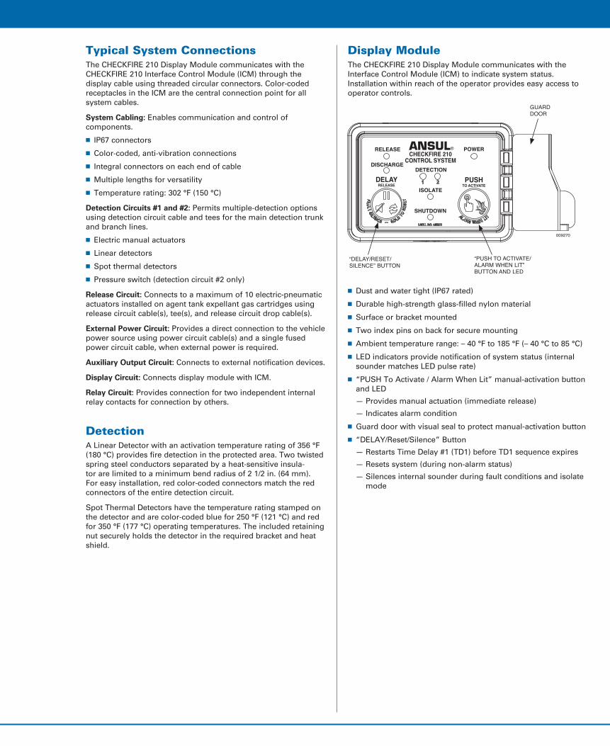
Display ModuleThe CHECKFIRE 210 Display Module communicates with the Interface Control Module (ICM) to indicate system status. Installation within reach of the operator provides easy access to operator controls.
n Dust and water tight (IP67 rated)
n Durable high-strength glass-filled nylon material
n Surface or bracket mounted
n Two index pins on back for secure mounting
n Ambient temperature range: – 40 °F to 185 °F (– 40 °C to 85 °C)
n LED indicators provide notification of system status (internal sounder matches LED pulse rate)
n “PUSH To Activate / Alarm When Lit” manual-activation button and LED
— Provides manual actuation (immediate release)
— Indicates alarm condition
n Guard door with visual seal to protect manual-activation button
n “DELAY/Reset/Silence” Button
— Restarts Time Delay #1 (TD1) before TD1 sequence expires
— Resets system (during non-alarm status)
— Silences internal sounder during fault conditions and isolate mode
Release ciRcuit cable and tees
Relay ciRcuit cable
checkfiRe 210 disPlay module and bRacket
Visual seal
lineaR detectoR
sPot theRmal detectoRs (install with heat shield and bRacket)
electRic manual actuatoR and bRacket
bRanch teRminatoR (on end of detectoR)
PoweR ciRcuit cable
fused PoweR ciRcuit cable
detection ciRcuit cable and teeseol
deVice
aGent tank
Release ciRcuit dRoP cable
electRic- Pneumatic actuatoR
exPellant Gas caRtRidGe
009269
CHECKFIRE 210 SYSTEM – SAMPLE CONNECTIONS
“delay/Reset/silence” button
“Push to actiVate/alaRm when lit” button and led
ANSUL®
CHECKFIRE 210CONTROL SYSTEM
POWERRELEASE
DISCHARGE
DELAYRELEASE
PUSHTO ACTIVATE
ISOLATE
DETECTION
SHUTDOWN
009270
GuaRddooR
disPlaycable
Relaycable-leads
batteRycomPaRtment
isolateswitch
coloR-coded RecePtacles (7 Places) 009271
inteRface contRol module
Interface Control Module (ICM)The CHECKFIRE 210 Interface Control Module (ICM) is the central connection point for input/output circuits. Through communication with the display module, operators receive continuous system status updates, and operator input commands go directly to the ICM. Color-coded receptacles match with color-coded cable connectors providing quick visual confirmation of proper circuit connections.
The protective battery compartment cover is held in place with 4 captive screws. Besides the internal power supply, the battery compartment includes the battery cable, a mini USB connection port, and the programming interface (button and LEDs). The system programming may be accomplished with the manual programming button and indicator LEDs or by using a computer with the ANSUL CHECKFIRE 210 Programmer software communicating through the mini USB port.
An isolate switch on the side of the ICM provides ease of access to temporarily disable the automatic system release function. While disabled, manual system release is still available. An amber isolate LED on the display module continues to pulse until the switch is returned to normal.
n Dust and water tight (IP67 rated)
n Durable high-strength glass-filled nylon
n UL94 Flame rating
n Ambient temperature range: – 40 °F to 185 °F (– 40 °C to 85 °C)
n Internal battery compartment with IP67 covern System isolate switch
n Steel mounting plate
009267
Battery ModuleA supervised 3.6 VDC lithium CHECKFIRE 210 Battery Module provides internal power for the CHECKFIRE 210 System. A connector pigtail extending from the top of the battery connects to the ICM battery cable.
Electric-Pneumatic ActuatorWith a focus on ease of installation and safety, the Electric-Pneumatic Actuator reduces system complex-ity. The Protracting Actuation Device (PAD) directly actuates the electric-pneumatic actuator pin eliminating the need for pneumatic actuation.
The re-designed PAD with plug-in spade connectors is easy to install and replace without tools. After plugging the PAD into the release circuit drop cable, the cable is hand-tighted to the top of the electric-pneumatic actuator.
009261
For installer safety during assembly of the Electric-Pneumatic Actuator to an expellant gas cartridge, the actuator includes a new preventor. The integral preven-tor reduces the possibility of attaching the actuator with the pin not completely retracted. It also provides a metal to metal seat with the expellant gas cartridge eliminating the spacing washer.
If required, optional pneumatic actuation is available.
Typical System ConnectionsThe CHECKFIRE 210 Display Module communicates with the CHECKFIRE 210 Interface Control Module (ICM) through the display cable using threaded circular connectors. Color-coded receptacles in the ICM are the central connection point for all system cables.
System Cabling: Enables communication and control of components.
n IP67 connectors
n Color-coded, anti-vibration connections
n Integral connectors on each end of cable
n Multiple lengths for versatility
n Temperature rating: 302 °F (150 °C)
Detection Circuits #1 and #2: Permits multiple-detection options using detection circuit cable and tees for the main detection trunk and branch lines.
n Electric manual actuators
n Linear detectors
n Spot thermal detectors
n Pressure switch (detection circuit #2 only)
Release Circuit: Connects to a maximum of 10 electric-pneumatic actuators installed on agent tank expellant gas cartridges using release circuit cable(s), tee(s), and release circuit drop cable(s).
External Power Circuit: Provides a direct connection to the vehicle power source using power circuit cable(s) and a single fused power circuit cable, when external power is required.
Auxiliary Output Circuit: Connects to external notification devices.
Display Circuit: Connects display module with ICM.
Relay Circuit: Provides connection for two independent internal relay contacts for connection by others.
DetectionA Linear Detector with an activation temperature rating of 356 °F (180 °C) provides fire detection in the protected area. Two twisted spring steel conductors separated by a heat-sensitive insula-tor are limited to a minimum bend radius of 2 1/2 in. (64 mm). For easy installation, red color-coded connectors match the red connectors of the entire detection circuit.
Spot Thermal Detectors have the temperature rating stamped on the detector and are color-coded blue for 250 °F (121 °C) and red for 350 °F (177 °C) operating temperatures. The included retaining nut securely holds the detector in the required bracket and heat shield.
Display ModuleThe CHECKFIRE 210 Display Module communicates with the Interface Control Module (ICM) to indicate system status. Installation within reach of the operator provides easy access to operator controls.
n Dust and water tight (IP67 rated)
n Durable high-strength glass-filled nylon material
n Surface or bracket mounted
n Two index pins on back for secure mounting
n Ambient temperature range: – 40 °F to 185 °F (– 40 °C to 85 °C)
n LED indicators provide notification of system status (internal sounder matches LED pulse rate)
n “PUSH To Activate / Alarm When Lit” manual-activation button and LED
— Provides manual actuation (immediate release)
— Indicates alarm condition
n Guard door with visual seal to protect manual-activation button
n “DELAY/Reset/Silence” Button
— Restarts Time Delay #1 (TD1) before TD1 sequence expires
— Resets system (during non-alarm status)
— Silences internal sounder during fault conditions and isolate mode
Release ciRcuit cable and tees
Relay ciRcuit cable
checkfiRe 210 disPlay module and bRacket
Visual seal
lineaR detectoR
sPot theRmal detectoRs (install with heat shield and bRacket)
electRic manual actuatoR and bRacket
bRanch teRminatoR (on end of detectoR)
PoweR ciRcuit cable
fused PoweR ciRcuit cable
detection ciRcuit cable and teeseol
deVice
aGent tank
Release ciRcuit dRoP cable
electRic- Pneumatic actuatoR
exPellant Gas caRtRidGe
009269
CHECKFIRE 210 SYSTEM – SAMPLE CONNECTIONS
“delay/Reset/silence” button
“Push to actiVate/alaRm when lit” button and led
ANSUL®
CHECKFIRE 210CONTROL SYSTEM
POWERRELEASE
DISCHARGE
DELAYRELEASE
PUSHTO ACTIVATE
ISOLATE
DETECTION
SHUTDOWN
009270
GuaRddooR
disPlaycable
Relaycable-leads
batteRycomPaRtment
isolateswitch
coloR-coded RecePtacles (7 Places) 009271
inteRface contRol module

Features n Supervised power, detection, release, and communication
circuits
n Display module with LED system status indicators
n Adjustable mounting bracket (display module)
n 85 dB internal sounder
n Compact size
n Automatic and/or manual actuation
n Electric “DELAY/Reset/Silence” button
n “PUSH To Activate / Alarm When Lit” electric manual activation button
n Interface control module for all color-coded “Plug and Play” cable connections
n Cables provide quick installation and easy replacement
n Internal power source with optional external power
n Auxiliary power output when external power is connected
n Manual programming at interface control module
n Computer programming available through mini USB port
n Two programmable release time delays
n Two analog detection circuits
n Detection circuits are programmable for multiple detection methods
n Detection circuit #2 may be programmed for pressure switch feedback
n Two internal programmable SPDT Form C relays (5 A @ 30 VDC nominal automotive)
n Downloadable 4000+ event history log with real-time stamp
n System isolate feature
n Dust and water tight (IP67 rated)
n Designed for harsh environments
009266
ApplicationThe CHECKFIRE 210 Detection and Actuation System is typically used with an ANSUL® A-101 or LVS Vehicle Fire Suppression System for 24-hour protection of equipment. The system is designed for vehicles and equipment in extreme environmental and physical conditions.
Industries where vehicles use CHECKFIRE 210 Systems:
n Forestry n Land fills
n Agriculture n Waste disposal
n Construction n Mining
n Public transportation
n Public utilities
DescriptionThe CHECKFIRE 210 Automatic Detection and Actuation System provides supervised input/output circuits to activate an ANSUL® fire suppression system. Upon detecting a fire condition, the interface control module activates the release circuit, resulting in the discharge of an expellant gas cartridge, initiating fire suppres-sion system operation.
Green, amber, and/or red pulsing LEDs, and the internal sounder notify operator of system status. The sounder only activates for faults, isolate mode, and system release.
Operating components include the display module, interface control module, spot thermal detectors, linear detectors, electric manual actuators, protracting actuation devices (PAD), electric-pneumatic actuators, and cables for power, detection, and release circuits. The entire system is electronics based for supervision, communication, and control of system components.
One Stanton Street / Marinette, WI 54143-2542, USA / +1-715-735-7411 / www.ansul.comCopyright © 2014 Tyco Fire Products LP. / All rights reserved. / Form No. F-2014011
Electric Manual ActuatorThe newly designed Electric Manual Actuator (EMA) provides electrical activation of the fire suppression system. Pulling the pin and striking the red button sends a signal to the interface control module for immediate actuation of the electric-pneumatic actuator. Upon actuation, the expellant gas cartridge initiates fire suppression system operation.
009262
EMAs are typically accessible from ground level and/or in a path of egress. An index nub ensures the EMA remains at the proper angle for access to the pull pin.
009268
System Specifications Interface Control Module Power: Internal power source
and/or: 12/24 VDC nominal external power (24 hour operation)
Operating Temperature Range: – 40 °F to 185 °F
(– 40 °C to 85 °C)
Shock: In accordance with UL1254
Vibration: In accordance with UL1254
Moisture and Dust: IP67 per IEC 60529
Electromagnetic Compatibility: Heavy Industrial EMC Directive
Compliant (2004/108/EC)
ApprovalsFM Approved and CE Marked
Ordering InformationPart No. Description
System Components439560 Display Module, CHECKFIRE 210439564 Mounting Bracket, CHECKFIRE 110/210439561 Interface Control Module, CHECKFIRE 210439569 Electric-Pneumatic Actuator
(normally supplied with agent tanks)439400 Electric Manual Actuator (EMA)440537 Electric Manual Actuator Bracket
Detection Circuit Cables and Fittings439384 Cable, Detection Circuit, 2 ft (0.61 m)439386 Cable, Detection Circuit, 5 ft (1.53 m)439388 Cable, Detection Circuit, 10 ft (3.05 m)439390 Cable, Detection Circuit, 20 ft (6.10 m)440759 Cable, Detection Circuit, 30 ft (9.15 m)440762 Cable, Detection Circuit, 50 ft (15.24 m)439394 Connector, Tee, Detection Circuit (MxFxF)439396 Connector, EOL Device, Detection Circuit439398 Connector, Branch Terminator, Detection Circuit439404 Connector, Bulkhead, Detection Circuit
Linear Detectors439406 Linear Detector, 2 ft (0.61 m)439478 Linear Detector, 5 ft (1.53 m)439480 Linear Detector, 10 ft (3.05 m)439408 Linear Detector, 20 ft (6.10 m)439410 Linear Detector, 30 ft (9.15 m)440765 Linear Detector, 50 ft (15.24 m)
Release Circuit Cables and Fittings439418 Cable, Release Circuit, 2 ft (0.61 m)439420 Cable, Release Circuit, 5 ft (1.53 m)439422 Cable, Release Circuit, 10 ft (3.05 m)439424 Cable, Release Circuit, 20 ft (6.10 m)439426 Cable, Release Circuit, 30 ft (9.15 m)439428 Cable, Release Circuit, 50 ft (15.24 m)439430 Cable, Release Circuit Drop, 30 in. (0.77 m)439432 Cable, Release Circuit Drop, 38 in. (0.97 m) 439434 Connector, Tee, Release Circuit (MxFxF)439436 Connector, Release Circuit Terminator439405 Connector, Bulkhead, Release and Power Circuits439448 Protracting Actuation Device (PAD),
w/Spade Connectors
Part No. Description
Display Cables439452 Cable, Display, 2 ft (0.61)439454 Cable, Display, 5 ft (1.53)439456 Cable, Display, 10 ft (3.05)439458 Cable, Display, 20 ft (6.10)439460 Cable, Display, 30 ft (9.15)439462 Cable, Display, 50 ft (15.24) 439449 Connector, Bulkhead, Display Cable
Relay #1 & #2 Circuit Cable439466 Cable, Relay Cable-Leads, 3 ft (0.91)440410 Cable, Backup Power/Relay Circuit, 2 ft (0.61 m)440413 Cable, Backup Power/Relay Circuit, 5 ft (1.53 m)439482 Cable, Backup Power/Relay Circuit, 10 ft (3.05 m)440416 Cable, Backup Power/Relay Circuit, 20 ft (6.10 m)
Auxiliary Output Circuit Cable 439450 Cable, Auxiliary Power Output Circuit, 3 ft (0.91)
Power Circuit Cables and Fittings439438 Cable, Power Circuit, 2 ft (0.61 m)439440 Cable, Power Circuit, 5 ft (1.53 m)439442 Cable, Power Circuit, 10 ft (3.05 m)439444 Cable, Power Circuit, 20 ft (6.10 m)439446 Cable, Power Circuit, 30 ft (9.15 m)440187 Cable, Power Circuit, 50 ft (15.24 m)439405 Connector, Bulkhead, Release and Power Circuits439492 Cable, Fused Power Circuit, (w/Inline Fuse Holder),
3 ft (0.91 m)
Accessory Equipment440362 ICM Battery Module, CHECKFIRE 210438280 Spot Thermal Detector, 250 °F (121 °C) 438281 Spot Thermal Detector, 350 °F (177 °C) 440905 Spot Thermal Detector Bracket and Heat Shield
440389 Pressure Switch
440737 Double-Loop Cable Ties (Pkg. of 50)56692 Rubber Sleeve (Pkg. of 20)
440798 Label Package
440097 Detection Circuit Tester (DCT)441021 Release Circuit Tester (RCT)440912 Release Circuit Test Plug (Pkg. of 3)
CHECKFIRE 210 Detection and Actuation System
DATA SHEET