check valve (next generation) - opwglobal.com
TRANSCRIPT
P/N: A-180/A-183, Rev. 6.2 Issue Date: January 12, 2018
Supersedes: A-180/A-183, Rev. 6.1
Manual content is subject to change. Visit www.midlandmfg.com for latest manual revision and revision history.
Check Valve (Next Generation) A-180 and A-183 Series Installation, Operation & Maintenance (IOM) Manual
Manual content is subject to change. Visit midlandmfg.com for latest manual revision and revision history.
A-180/A-183, Rev. 6.2 Page 2 of 14
Table of Contents " Introduction ......................................................................................................................................... 3
Valve Dimensions and Details .................................................................................................. 3
6 Installation .......................................................................................................................................... 4
Installation Weld Procedure ...................................................................................................... 4
: Testing ................................................................................................................................................ 6
Testing Procedure .................................................................................................................... 6
> Valve Disassembly ............................................................................................................................. 7
Disassembly on Cover Plate ..................................................................................................... 7
Inspection ............................................................................................................................... 12
Reassembly Procedure on Cover Plate .................................................................................. 13

Manual content is subject to change. Visit midlandmfg.com for latest manual revision and revision history.
A-180/A-183, Rev. 6.2 Page 3 of 14
1 Introduction Valve Dimensions and Details
Item Qty. Part Name
1 1 Guide
2 1 Retainer
3 1 Seat
4 1 Body
5 1 Spring
6 1 Seat Seal
7 1 O-Ring
8 1 Insert
9 1 Gasket
CAUTION: Spring loaded assembly. NOTE: Use assembly tool T-180 to install/remove guide.
Table 1-1 Valve Component Details
Figure 1-1 Valve Components – A-180 Figure 1-2 Valve Components – A-183
Manual content is subject to change. Visit midlandmfg.com for latest manual revision and revision history.
A-180/A-183, Rev. 6.2 Page 4 of 14
2 Installation Installation Weld Procedure
NOTICE: Conform to all regulations and your company’s installation and testing instructions when installing this valve. It is not the intention of this pamplet to conflict with or supersede those requirements.
Insert the check valve asssembly in the socket in the bottom of the cover plate.
TIP: Prior to welding, position the body so there is a 0.06” gap at the bottom of the socket.
Filler Metal Selection
NOTICE:
Fit-Up: Adding filler metal to fill gaps puts more heat into the part, so good fit-up is important. It’s impossible to add a lot of filler metal and keep energy out of the part. Filler Metal: The filler metal diameter should be thinner than the base metal. If it’s thicker than the base metal, too much heat is needed to melt the filler metal. The filler metal should also match the base metal alloys in order to maintain consistent mechanical and corrosion properties. Tungsten Size: Use the right tungsten diameter based on your amperage.
6
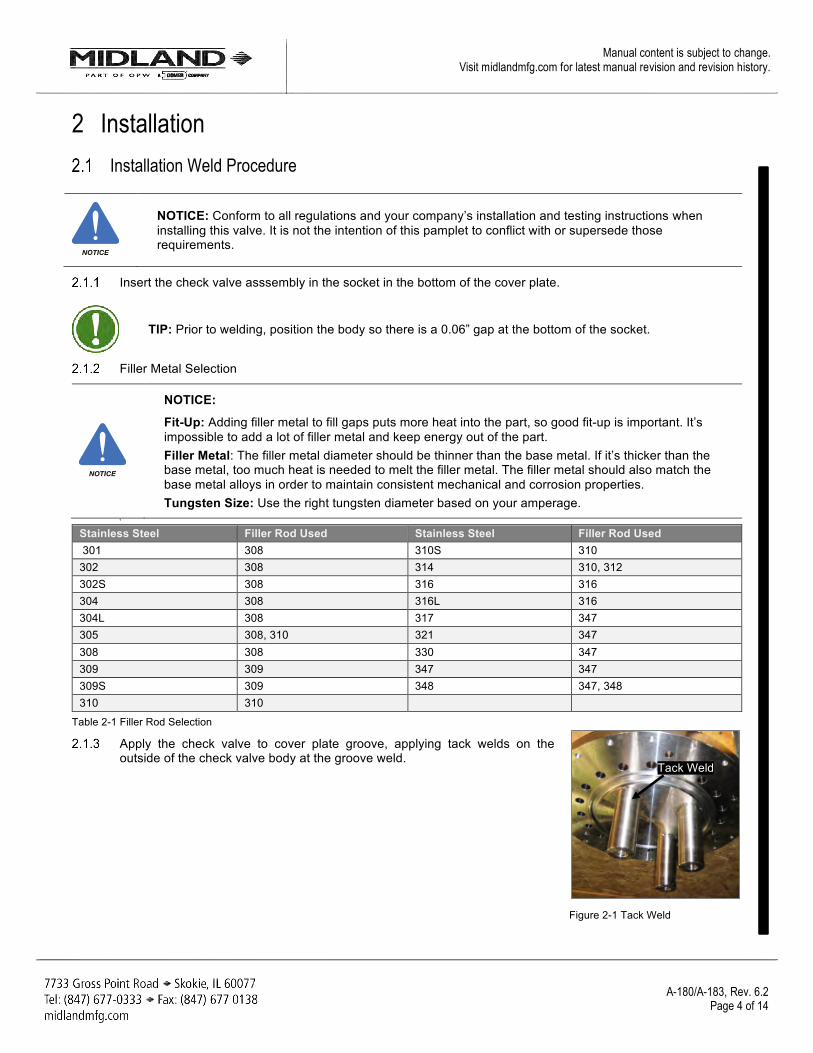
Stainless Steel Filler Rod Used Stainless Steel Filler Rod Used 301 308 310S 310 302 308 314 310, 312 302S 308 316 316 304 308 316L 316 304L 308 317 347 305 308, 310 321 347 308 308 330 347 309 309 347 347 309S 309 348 347, 348 310 310
Table 2-1 Filler Rod Selection
Apply the check valve to cover plate groove, applying tack welds on the outside of the check valve body at the groove weld.
Figure 2-1 Tack Weld
NOTICE
NOTICE
Tack Weld

Manual content is subject to change. Visit midlandmfg.com for latest manual revision and revision history.
A-180/A-183, Rev. 6.2 Page 5 of 14
NOTICE: Use an AWS approved FCAW or SMAW Welding Procedure Specification (WPS) with ER308 type electrodes (per AWS A5.20 or A5.1 electrode specification).
Check the valve body to be square to the bottom surface of the cover plate. Verify 3.23 ± 0.05 dimension.
Figure 2-2 Verify Dimensions
If assembly is positioned within tolerances, make seal weld all around and final fillet weld.
Weld the outside fillet weld, taking care to adhere to the maximum interpass temperature to avert body distortion.
CAUTION: It is important to control material deformation caused by heat. Do not exceed the maximum interpasss temperature of 300 degrees Fahrenheit for the welding of the check valve to the pressure plate.
Figure 2-3 Fillet Weld
Chip and wire brush all slag and foreign material from each applied pass. Remove all undercuts and slag.
NOTICE: All welded surfaces and adjacent joining base metal surfaces shall be free of cracks, inclusions, undercuts and porosity. For quality assurance, perform final visual inspection.
Allow weld to cool to below maximum interpass temperature and then remove welded “dogs” (if applicable).
For quality assurance, visually inspect and dye penetrant inspect per AAR C-III, Appendix W, Sect. 11.3 to confirm the weld applied is free of any surface defects.
Perform and document localized Post Weld Heat Treatment (PWHT) if necessary.
NOTICE
CAUTION
NOTICE
Fillet Weld

Manual content is subject to change. Visit midlandmfg.com for latest manual revision and revision history.
A-180/A-183, Rev. 6.2 Page 6 of 14
3 Testing Testing Procedure Follow your company’s procedure for testing.
There are three (3) primary areas to check.
• Valve seat
• Seal between seat and body below 3”-12UN or 3-1/2”-12UN thread
• Weld joint between valve body and cover plate
3.1.2.1 If it does not seal completely, disassemble valve per Maintenance instructions.
Manual content is subject to change. Visit midlandmfg.com for latest manual revision and revision history.
A-180/A-183, Rev. 6.2 Page 7 of 14
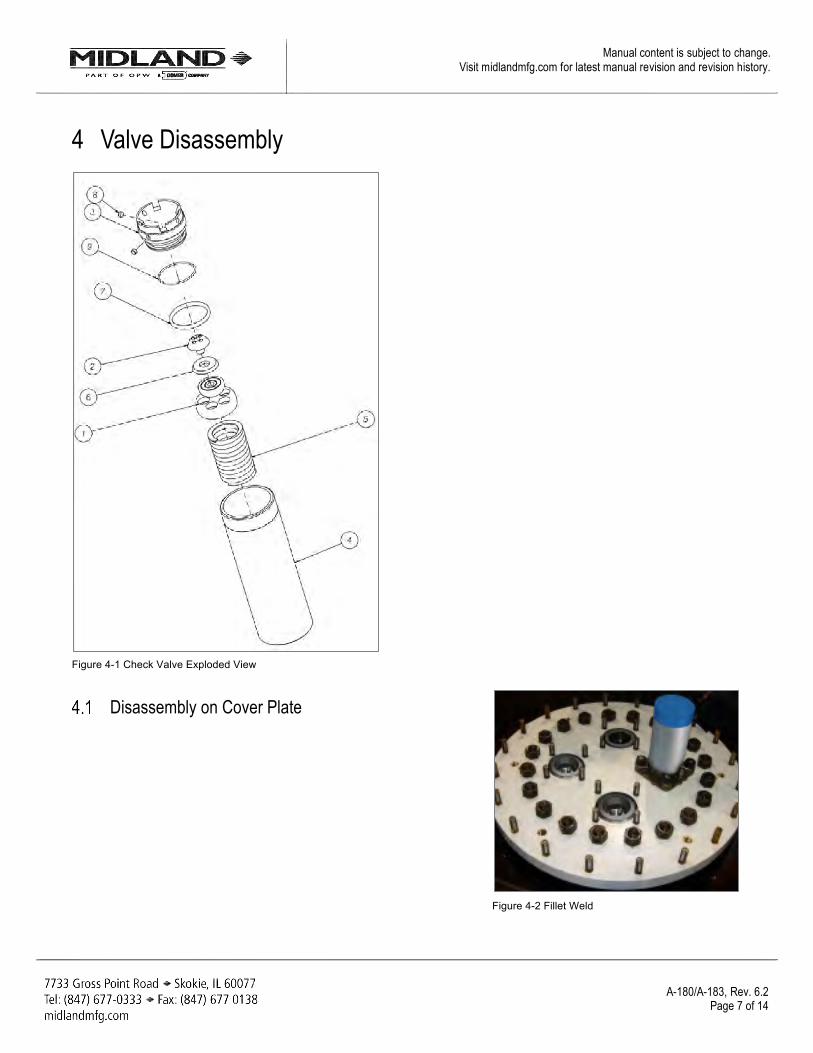
4 Valve Disassembly
Figure 4-1 Check Valve Exploded View
Disassembly on Cover Plate
Figure 4-2 Fillet Weld

Manual content is subject to change. Visit midlandmfg.com for latest manual revision and revision history.
A-180/A-183, Rev. 6.2 Page 8 of 14
CAUTION: When valves are disassembled by an AAR registered facility, all work must be done in a clean and debris-free environment.
Remove the angle valve from the cover plate.
Use the T-A-180 tool to disassemble the valve.
Figure 4-3 T-A-180 Tool
CAUTION

Manual content is subject to change. Visit midlandmfg.com for latest manual revision and revision history.
A-180/A-183, Rev. 6.2 Page 9 of 14
Install bushing in the check valve seat with the cross protrusion engaged in four (4) slots located on top of the seat.
Figure 4-4 Install Bushing
Install the tool over bushing. Make sure it fits in the groove in the cover plate and fasten to the plate with two (2) ¾-10 heavy hex nuts.
Figure 4-5 Install Tool Over Bushing
Manual content is subject to change. Visit midlandmfg.com for latest manual revision and revision history.
A-180/A-183, Rev. 6.2 Page 10 of 14
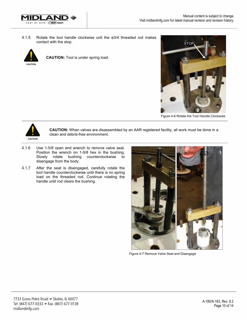
Rotate the tool handle clockwise unti the ø3/4 threaded rod makes contact with the stop.
CAUTION: Tool is under spring load.
Figure 4-6 Rotate the Tool Handle Clockwise
CAUTION: When valves are disassembled by an AAR registered facility, all work must be done in a clean and debris-free environment.
Use 1-5/8 open end wrench to remove valve seat. Position the wrench on 1-5/8 hex in the bushing. Slowly rotate bushing counterclockwise to disengage from the body.
After the seat is disengaged, carefully rotate the tool handle counterclockwise until there is no spring load on the threaded rod. Continue rotating the handle until rod clears the bushing.
Figure 4-7 Remove Valve Seat and Disengage
CAUTION
CAUTION
STOP
Manual content is subject to change. Visit midlandmfg.com for latest manual revision and revision history.
A-180/A-183, Rev. 6.2 Page 11 of 14
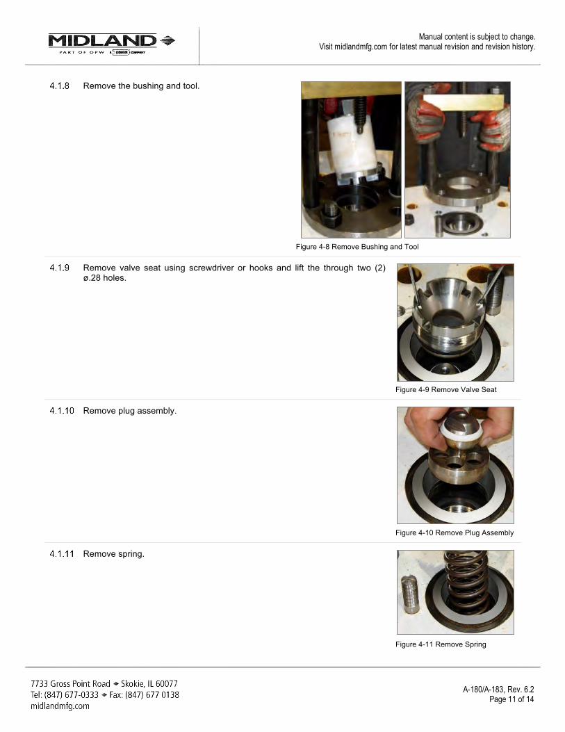
Remove the bushing and tool.
Figure 4-8 Remove Bushing and Tool
Remove valve seat using screwdriver or hooks and lift the through two (2) ø.28 holes.
Figure 4-9 Remove Valve Seat
Remove plug assembly.
Figure 4-10 Remove Plug Assembly
Remove spring.
Figure 4-11 Remove Spring
Manual content is subject to change. Visit midlandmfg.com for latest manual revision and revision history.
A-180/A-183, Rev. 6.2 Page 12 of 14
Inspection
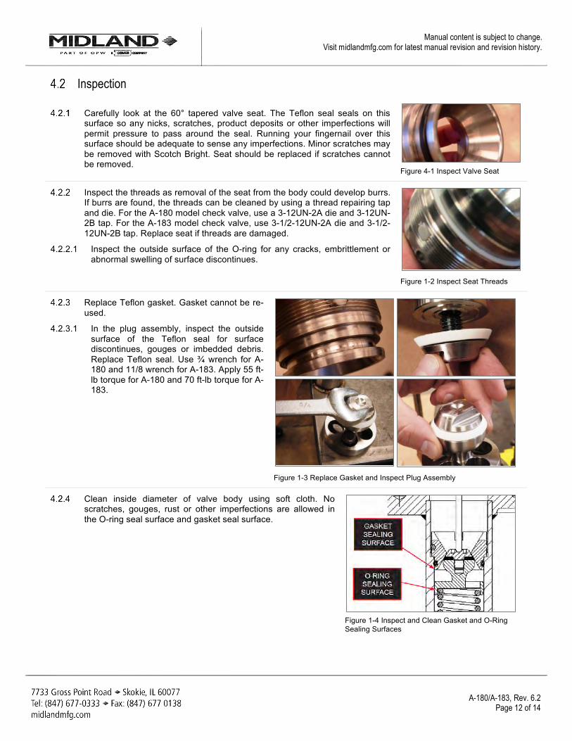
Carefully look at the 60° tapered valve seat. The Teflon seal seals on this surface so any nicks, scratches, product deposits or other imperfections will permit pressure to pass around the seal. Running your fingernail over this surface should be adequate to sense any imperfections. Minor scratches may be removed with Scotch Bright. Seat should be replaced if scratches cannot be removed.
Figure 4-1 Inspect Valve Seat
Inspect the threads as removal of the seat from the body could develop burrs. If burrs are found, the threads can be cleaned by using a thread repairing tap and die. For the A-180 model check valve, use a 3-12UN-2A die and 3-12UN-2B tap. For the A-183 model check valve, use 3-1/2-12UN-2A die and 3-1/2-12UN-2B tap. Replace seat if threads are damaged.
4.2.2.1 Inspect the outside surface of the O-ring for any cracks, embrittlement or abnormal swelling of surface discontinues.
Figure 1-2 Inspect Seat Threads
Replace Teflon gasket. Gasket cannot be re-used.
4.2.3.1 In the plug assembly, inspect the outside surface of the Teflon seal for surface discontinues, gouges or imbedded debris. Replace Teflon seal. Use ¾ wrench for A-180 and 11/8 wrench for A-183. Apply 55 ft-lb torque for A-180 and 70 ft-lb torque for A-183.
Figure 1-3 Replace Gasket and Inspect Plug Assembly
Clean inside diameter of valve body using soft cloth. No scratches, gouges, rust or other imperfections are allowed in the O-ring seal surface and gasket seal surface.
Figure 1-4 Inspect and Clean Gasket and O-Ring Sealing Surfaces

Manual content is subject to change. Visit midlandmfg.com for latest manual revision and revision history.
A-180/A-183, Rev. 6.2 Page 13 of 14
Reassembly Procedure on Cover Plate To reassemble valve on cover plate, reverse disassembly steps using T-A-180 tool.
If lubricant is permitted for application, select a compound that is compatible with lading and lubricate threads, O-ring groove and O-ring in the seat assembly prior to valve reassembly. Tighten the seat until it stops. Do not use excessive force.
Figure 0-1 Lubricate If Needed and Tighten Seat
Remove installation tool and verify seat position (3.23 ± 0.05 dimension).
Figure 0-2 Inspect Valve Seat
Test assembly.