chassis cab vsim usage instructions ram trucks| ram ... · chassis cab vsim usage instructions vsim...
TRANSCRIPT

Chassis Cab VSIM Usage Instructions Ram Trucks| Ram Engineering | Vehicle System Interface Module Video
VSIM (VEHICLE SYSTEM INTERFACE MODULE) USAGE INSTRUCTIONS
Overview:
The RAM Truck engineered upfitter module called the VSIM (Vehicle System Interface Module) with sales code “XXS” is standard with Ambulance Prep (sales code AH2), a “must have” option with PTO Prep (sales codes LBN or LBV), and is available as a stand-alone option. It provides a multitude of useful I/O’s to increase upfitter friendliness and upfit simplification. Vehicles not ordered with this option from the factory cannot be retrofitted.
Specifics supplied below:
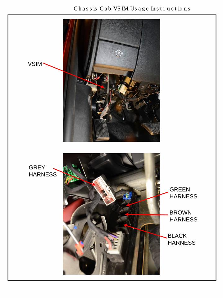
1. Ghost drawings showing the module location within the dash panel.2. The VSIM includes an upfitter wire harness kit (part number 68319578AA) consisting of four separate
color coded harness bundles. Each individual color harness must only be plugged into itscorresponding VSIM connector cavity, see photos below showing harness color installations.
3. A photo of the four individual color coded VSIM upfitter harness bundles. Note that in a fewinstances an individual wire color is duplicated within a bundle – these duplications are furtheridentified with a paper “flag” showing its circuit number. It’s recommended that the upfitter, uponharness bundle routing direction determination(s), install additional harness bundle abrasionprotection over each bundle (such as harness convolute).
4. Photos showing module installation within a vehicle and harness bundles.5. A chart below delineates the circuits within each color harness bundle, circuit number, signal, wire
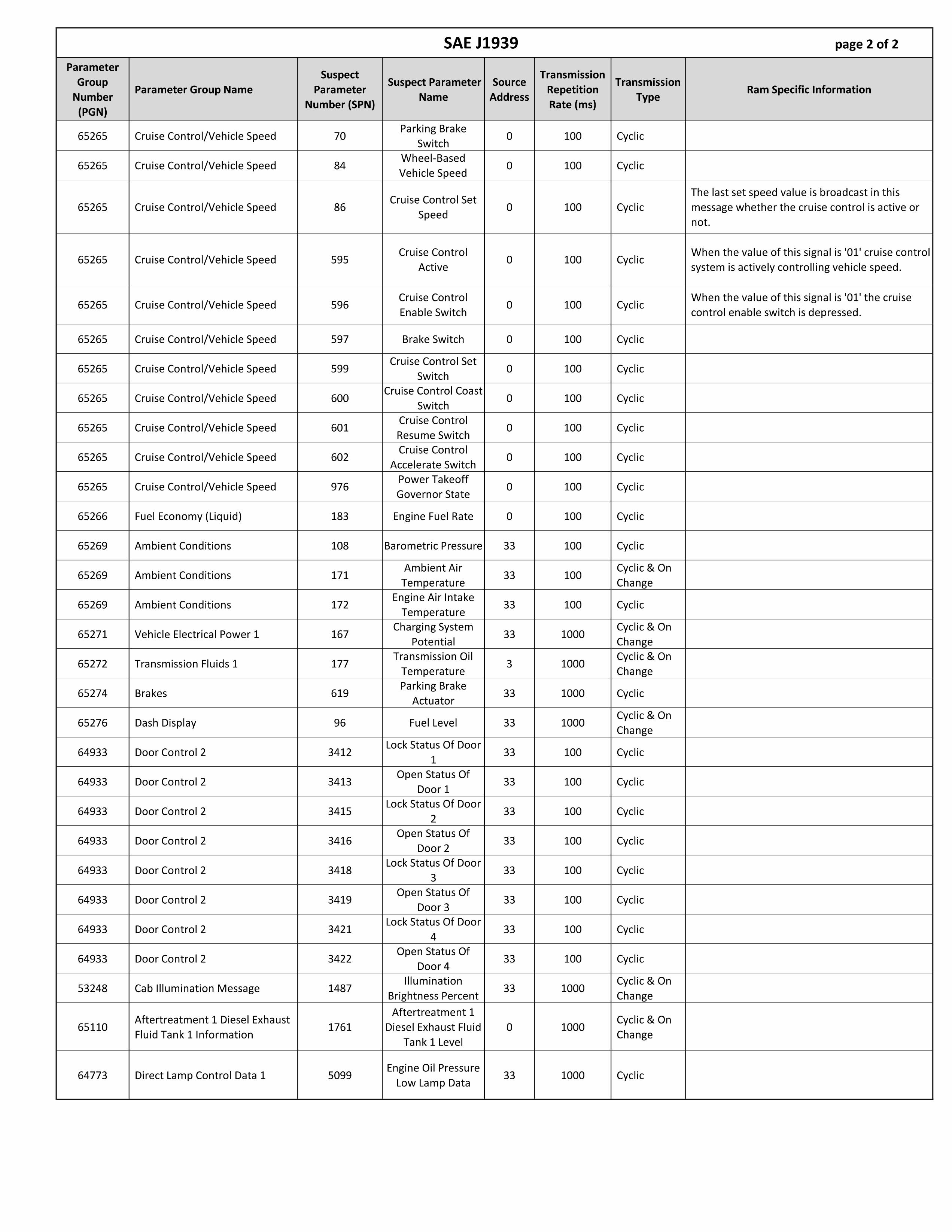
insulation colors, maximum allowable amperage per circuit, and circuit function.6. A chart below delineates the available 250K J1939 Bus messages.7. Note 3: PTO idle speed circuits W541, W542, W543 can only be programmed to function if the
vehicle was built with PTO option sales codes LBN or LBV.
VSIM

Chassis Cab VSIM Usage Instructions
Blunt cut and heat shrunk insulations;to be cut off as necessary Duplicate wire color circuit # tag
VSIM
Chassis Cab VSIM Usage Instructions
VSIM
GREYHARNESS
GREEN HARNESS
BROWN HARNESS
BLACKHARNESS

Chassis Cab VSIM Usage Instructions
GREYHARNESS
GREENHARNESS
BROWNHARNESSNote: When
inserting theVSIM harness BLACKconnectors an HARNESSaudible “click”will be heardwhen theconnector isfully seated.

1 Not Used Not Used
2 Hazard indicator on - HSD output W719 WT/VT 0.5 HSD OutputOpen circuit when hazard flashers are off, battery positive voltage (+12V) when hazard flashers are
selected.
3 Transmission out of "Park" - HSD output W504 BR 0.5 HSD OutputOpen circuit when gear selector is in Park , battery positive voltage (+12V) when the gear selector is
in any other position.
4 Diesel Regeneration (DPF) on - HSD output W545 BR/LB 0.5 HSD OutputOpen circuit when diesel regeneration is not energized battery positive voltage (+12V) when it is
energized
5 PTO on indicator - HSD W743 VT/TN 1 HSD OutputOpen circuit when PTO circuit is not energized, battery positive voltage (+12V) when PTO circuit is
energized (W708 must be grounded [via PTO pressure switch) for this to function) output
6 MIL lamp on - HSD output W540 BR/DG 0.5 HSD Output Open circuit when MIL is not illuminated battery positive voltage (+12V) when MIL is illuminated
7 Transmission "Park" position - LSD output W700 YL/DB 0.5 LSD Output Open circuit when gear selector is not in Park, grounded when in Park.
8 Transmission "Neutral" position - LSD output W701 DG/YL 0.5 LSD Output Open circuit when gear selector is not in Neutral, grounded when in Neutral.
9 HVAC - A/C Clutch engaged - LSD output W652 LB/BR 0.5 LSD Output Open circuit when A/C Clutch is not engaged, grounded when engaged.
10 ** CAN communication J1939 + 250 Kbaud W532 BR/DB J1939 Bus (+)250 Kbaud J1939 CAN+, use in conjunction with W534, refer to J1939 spreadsheet for available
messages.
11 ** CAN communication J1939 - 250 Kbaud W534 BR/LB 0.5 J1939 Bus (-)250 Kbaud J1939 CAN-, use in conjunction with W532, refer to J1939 spreadsheet for available
messages.
12Transmission "Reverse" Position - LSD
outputW702 DG/DB 0.5 LSD Output Open circuit when gear selector is not in Reverse, grounded when in Reverse.
13 Not Used Not Used
14HVAC - when A/C is selected via the dash
switch - LSD outputW654 LB/OR 0.5 LSD Output Open circuit when A/C has not been selected, grounded when A/C has been selected.
15 Cargo Lamp Output (timer) - LSD output W711 WT/TN 0.5 LSD OutputActivated (grounded) when circuit W506 (cavity 4 of brown connector) is grounded. Open circuit
when off. Times out after 30 minutes. Re-enabled by cycling W506 switch.
16 Transmission "Drive" Position - LSD output W703 DG/LB 0.5 LSD Output Open circuit when gear selector is not in Drive, grounded when in Drive.
17 Any Door Ajar - HSD output W720 VT/OR 0.5 HSD Output Open circuit when all the doors are closed, battery voltage (+12V) when any door is ajar.
18 Not Used Not Used
19 Not Used Not Used
20 Not Used Not Used
21 Not Used Not Used
22 Not Used Not Used
23 Not Used Not Used
24 Not Used Not Used
VSIM 24 - CAVITY GRAY CONNECTOR
Cavity/Pin
#Upfitter VSIM Signal Circuit #
Wire
Color
Max
Current
(Amps)
FunctionType of Signal

1 Howler Siren disable - HSD output W505 LG HSD OutputOpen circuit when vehicle speed is below 25 MPH, battery positive voltage (+12V)
when vehicle speed is 25 MPH or above.
2 Horn activation - HSD output W513 BR/GY 0.5 HSD OutputOpen circuit when horn not pressed (not energized), battery positive voltage (+12V)
when pressed (energized).
3 Side Airbag deployed - HSD W517 BR/LG 0.5 HSD OutputOpen circuit when side airbags have not deployed during current key on cycle,
battery positive (+12V) upon airbag deployment during current key on cycle.
4Tire Pressure Monitor active - HSD output applicable
only RAM 2500 under 10,000 GVWW622 VT/YL 0.5 HSD Output
Open circuit when Tire Pressure Monitor (TPM) indicator lamp is off, battery
positive voltage (+12V) when the TPM indicator lamp is active.
5 Power feed "Off" - HSD output W735 PK 0.5 HSD OutputOpen circuit when key position is in "Accessory/Run/Start", battery positive (+12)
when key is in off position.
6 Driver Seat Belt not latched - HSD Output W710 LG/VT 0.5 HSD OutputOpen circuit when the drivers seat belt is latched, battery positive voltage (+12V)
when the drivers seat belt is not latched (key must be in "run" position.
7 Oil Pressure Warning Signal - LSD digital PWM output W707 VT/GY 0.1Digital Signal LSD
PWM Output
Oil Pressure Signal: Pulse Width Modulated (PWM) between open circuit and
ground, 100 Hz, linear with 0 % PWM = 0 PSI, and 100 % PWM = 147 PSI.
8 Voltage Gauge - LSD digital PWM output W733 VT 0.1Digital Signal LSD
PWM Output
Battery Voltage Signal: Pulse Width Modulated (PWM) between open circuit and
ground, 100 Hz, linear with 0 % PWM = 5V, and 100 % PWM = 18V.
9 Front Airbag Deployed - HSD ouput W518 BR/DG 0.5 HSD OutputOpen circuit when front airbags have not deployed during current key on cycle,
battery positive (+12V) upon front airbag deployment during current key on cycle.
10 Panic Alarm activation - HSD output W515 BR/LB 0.5 HSD OutputOpen circuit when Panic Alarm is not active, battery positive voltage (+12V) when
the Panic Alarm is active (key must be in "off" or "accessory" position).
11 Service Brake Pedal depressed W726 DG/OR 0.25 HSD OutputOpen circuit when Service Brake Pedal is not active, battery positive voltage (+12V)
when the Service Brake Pedal is active.
12 Power feed "Accessory" - HSD output W734 PK/GY 0.5 HSD OutputOpen circuit when key position is in "Off/Run/Start", battery positive (+12) when
key is in "Accessory" position.
13 Power feed "Run/Start" - HSD output W736 PK/YL 0.5 HSD OutputOpen circuit when key position is in "Off/Accessory", battery positive (+12) when
key is in "Run or Start" position.
14 Fuel Level Signal - LSD digital PWM output W538 BR/OR 0.1Digital Signal LSD
PWM Output
Fuel Level Signal: Pulse Width Modulated (PWM) between open circuit and ground,
100 Hz, linear with 0 % PWM = empty tank, and 100 % PWM = full tank.
15 Engine RPM Signal - LSD digital PWM output W744 BR/WT 0.25Digital Signal LSD
PWM Output
Engine RPM Signal : Pulse Width Modulated (PWM) between open circuit and
ground, 0.2 HZ/RPM (12 pulses per minute per 1 RPM) @50% duty cycle.
16Vehicle MPH speed signal -LSD Transmission "Drive"
Position - LSD outputW524 BR/YL 0.1
Digital Signal LSD
PWM Output
Vehicle Speed Signal: Modulation between open circuit and ground, output with 10
Hz/MPH (600 pulses per minute per 1 MPH) @50% duty cycle.
VSIM 16 - CAVITY BLACK CONNECTOR
Cavity/Pin
#Upfitter VSIM Signal Circuit #
Wire
Color
Max
Current
(Amps)
FunctionType of Signal
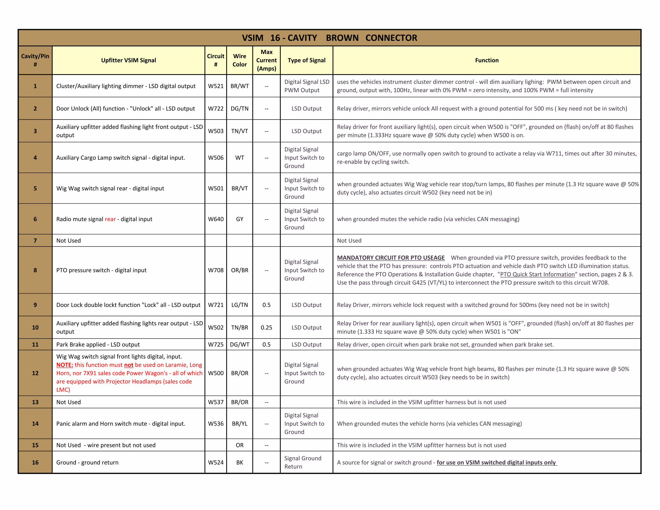
1 Cluster/Auxiliary lighting dimmer - LSD digital output W521 BR/WT --Digital Signal LSD
PWM Output
uses the vehicles instrument cluster dimmer control - will dim auxiliary lighing: PWM between open circuit and
ground, output with, 100Hz, linear with 0% PWM = zero intensity, and 100% PWM = full intensity
2 Door Unlock (All) function - "Unlock" all - LSD output W722 DG/TN -- LSD Output Relay driver, mirrors vehicle unlock All request with a ground potential for 500 ms ( key need not be in switch)
3Auxiliary upfitter added flashing light front output - LSD
outputW503 TN/VT -- LSD Output
Relay driver for front auxiliary light(s), open circuit when W500 is "OFF", grounded on (flash) on/off at 80 flashes
per minute (1.333Hz square wave @ 50% duty cycle) when W500 is on.
4 Auxiliary Cargo Lamp switch signal - digital input. W506 WT --
Digital Signal
Input Switch to
Ground
cargo lamp ON/OFF, use normally open switch to ground to activate a relay via W711, times out after 30 minutes,
re-enable by cycling switch.
5 Wig Wag switch signal rear - digital input W501 BR/VT --
Digital Signal
Input Switch to
Ground
when grounded actuates Wig Wag vehicle rear stop/turn lamps, 80 flashes per minute (1.3 Hz square wave @ 50%
duty cycle), also actuates circuit W502 (key need not be in)
6 Radio mute signal rear - digital input W640 GY --
Digital Signal
Input Switch to
Ground
when grounded mutes the vehicle radio (via vehicles CAN messaging)
7 Not Used Not Used
8 PTO pressure switch - digital input W708 OR/BR --
Digital Signal
Input Switch to
Ground
MANDATORY CIRCUIT FOR PTO USEAGE When grounded via PTO pressure switch, provides feedback to the
vehicle that the PTO has pressure: controls PTO actuation and vehicle dash PTO switch LED illumination status.
Reference the PTO Operations & Installation Guide chapter, "PTO Quick Start Information" section, pages 2 & 3.
Use the pass through circuit G425 (VT/YL) to interconnect the PTO pressure switch to this circuit W708.
9 Door Lock double lockt function "Lock" all - LSD output W721 LG/TN 0.5 LSD Output Relay Driver, mirrors vehicle lock request with a switched ground for 500ms (key need not be in switch)
10Auxiliary upfitter added flashing lights rear output - LSD
outputW502 TN/BR 0.25 LSD Output
Relay Driver for rear auxiliary light(s), open circuit when W501 is "OFF", grounded (flash) on/off at 80 flashes per
minute (1.333 Hz square wave @ 50% duty cycle) when W501 is "ON"
11 Park Brake applied - LSD output W725 DG/WT 0.5 LSD Output Relay driver, open circuit when park brake not set, grounded when park brake set.
12
Wig Wag switch signal front lights digital, input.
NOTE: this function must not be used on Laramie, Long
Horn, nor 7X91 sales code Power Wagon's - all of which
are equipped with Projector Headlamps (sales code
LMC)
W500 BR/OR --
Digital Signal
Input Switch to
Ground
when grounded actuates Wig Wag vehicle front high beams, 80 flashes per minute (1.3 Hz square wave @ 50%
duty cycle), also actuates circuit W503 (key needs to be in switch)
13 Not Used W537 BR/OR -- This wire is included in the VSIM upfitter harness but is not used
14 Panic alarm and Horn switch mute - digital input. W536 BR/YL --
Digital Signal
Input Switch to
Ground
When grounded mutes the vehicle horns (via vehicles CAN messaging)
15 Not Used - wire present but not used OR -- This wire is included in the VSIM upfitter harness but is not used
16 Ground - ground return W524 BK --Signal Ground
ReturnA source for signal or switch ground - for use on VSIM switched digital inputs only
VSIM 16 - CAVITY BROWN CONNECTOR
Cavity/Pin
#Upfitter VSIM Signal
Circuit
#
Wire
Color
Max
Current
(Amps)
FunctionType of Signal
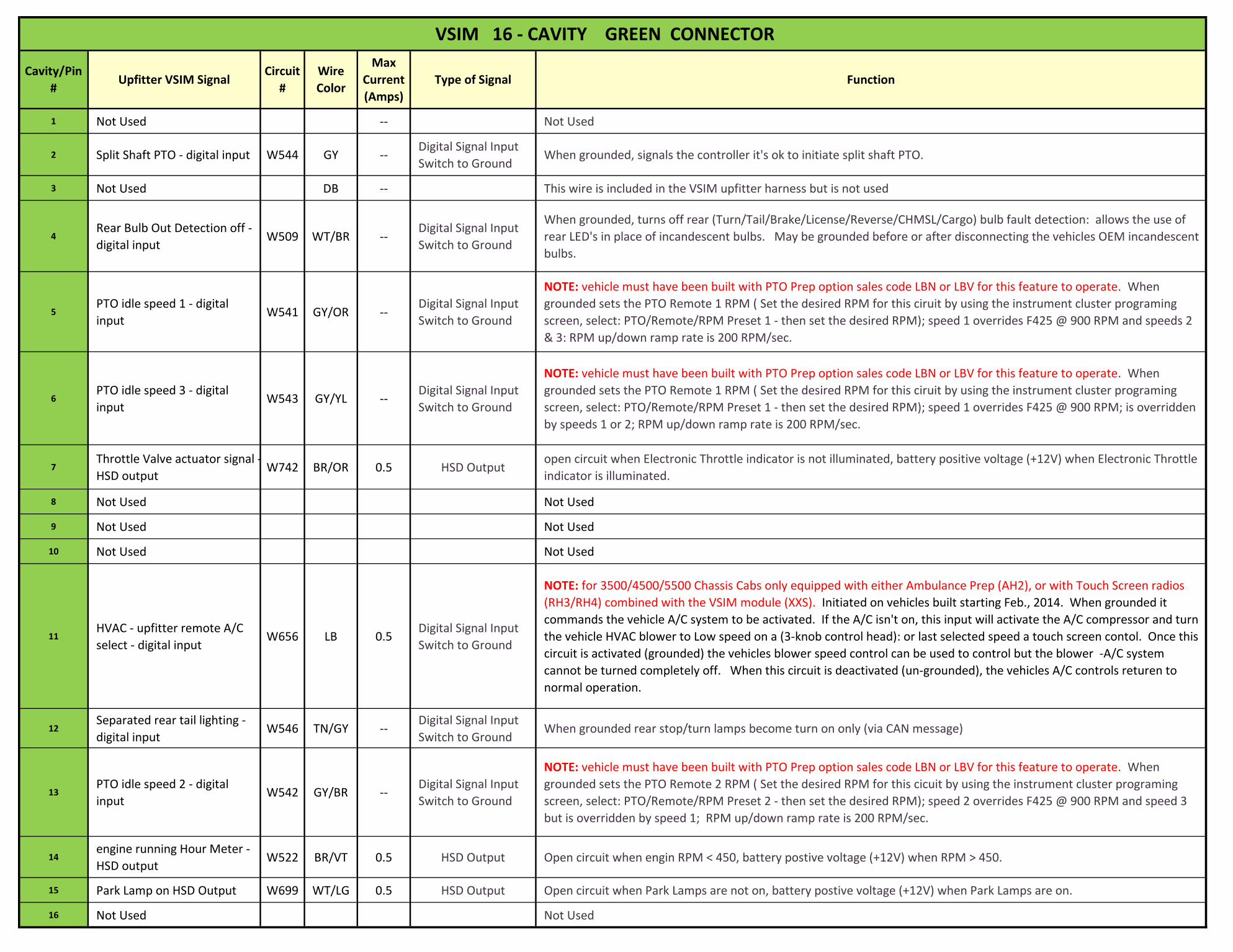
1 Not Used -- Not Used
2 Split Shaft PTO - digital input W544 GY --Digital Signal Input
Switch to GroundWhen grounded, signals the controller it's ok to initiate split shaft PTO.
3 Not Used DB -- This wire is included in the VSIM upfitter harness but is not used
4Rear Bulb Out Detection off -
digital inputW509 WT/BR --
Digital Signal Input
Switch to Ground
When grounded, turns off rear (Turn/Tail/Brake/License/Reverse/CHMSL/Cargo) bulb fault detection: allows the use of
rear LED's in place of incandescent bulbs. May be grounded before or after disconnecting the vehicles OEM incandescent
bulbs.
5PTO idle speed 1 - digital
inputW541 GY/OR --
Digital Signal Input
Switch to Ground
NOTE: vehicle must have been built with PTO Prep option sales code LBN or LBV for this feature to operate. When
grounded sets the PTO Remote 1 RPM ( Set the desired RPM for this ciruit by using the instrument cluster programing
screen, select: PTO/Remote/RPM Preset 1 - then set the desired RPM); speed 1 overrides F425 @ 900 RPM and speeds 2
& 3: RPM up/down ramp rate is 200 RPM/sec.
6PTO idle speed 3 - digital
inputW543 GY/YL --
Digital Signal Input
Switch to Ground
NOTE: vehicle must have been built with PTO Prep option sales code LBN or LBV for this feature to operate. When
grounded sets the PTO Remote 1 RPM ( Set the desired RPM for this ciruit by using the instrument cluster programing
screen, select: PTO/Remote/RPM Preset 1 - then set the desired RPM); speed 1 overrides F425 @ 900 RPM; is overridden
by speeds 1 or 2; RPM up/down ramp rate is 200 RPM/sec.
7Throttle Valve actuator signal -
HSD outputW742 BR/OR 0.5 HSD Output
open circuit when Electronic Throttle indicator is not illuminated, battery positive voltage (+12V) when Electronic Throttle
indicator is illuminated.
8 Not Used Not Used
9 Not Used Not Used
10 Not Used Not Used
11HVAC - upfitter remote A/C
select - digital inputW656 LB 0.5
Digital Signal Input
Switch to Ground
NOTE: for 3500/4500/5500 Chassis Cabs only equipped with either Ambulance Prep (AH2), or with Touch Screen radios
(RH3/RH4) combined with the VSIM module (XXS). Initiated on vehicles built starting Feb., 2014. When grounded it
commands the vehicle A/C system to be activated. If the A/C isn't on, this input will activate the A/C compressor and turn
the vehicle HVAC blower to Low speed on a (3-knob control head): or last selected speed a touch screen contol. Once this
circuit is activated (grounded) the vehicles blower speed control can be used to control but the blower -A/C system
cannot be turned completely off. When this circuit is deactivated (un-grounded), the vehicles A/C controls returen to
normal operation.
12Separated rear tail lighting -
digital inputW546 TN/GY --
Digital Signal Input
Switch to GroundWhen grounded rear stop/turn lamps become turn on only (via CAN message)
13PTO idle speed 2 - digital
inputW542 GY/BR --
Digital Signal Input
Switch to Ground
NOTE: vehicle must have been built with PTO Prep option sales code LBN or LBV for this feature to operate. When
grounded sets the PTO Remote 2 RPM ( Set the desired RPM for this cicuit by using the instrument cluster programing
screen, select: PTO/Remote/RPM Preset 2 - then set the desired RPM); speed 2 overrides F425 @ 900 RPM and speed 3
but is overridden by speed 1; RPM up/down ramp rate is 200 RPM/sec.
14engine running Hour Meter -
HSD outputW522 BR/VT 0.5 HSD Output Open circuit when engin RPM < 450, battery postive voltage (+12V) when RPM > 450.
15 Park Lamp on HSD Output W699 WT/LG 0.5 HSD Output Open circuit when Park Lamps are not on, battery postive voltage (+12V) when Park Lamps are on.
16 Not Used Not Used
VSIM 16 - CAVITY GREEN CONNECTOR
Cavity/Pin
#Upfitter VSIM Signal
Circuit
#
Wire
Color
Max
Current
(Amps)
FunctionType of Signal

Chassis Cab VSIM Usage Instructions

Parameter
Group Number
(PGN)
Parameter Group Name
Suspect
Parameter
Number (SPN)
Suspect Parameter
Name
Source
Address
Transmission
Repetition Rate
(ms)
Transmission
Type Ram Specific Information
61441 Electronic Brake Controller 1 561ASR Engine Control
Active11 100 Cyclic
ASR is RAM equivalent of Electronic Stability Control. There is no differentiation between
engine and braking control, both signals will be active at the same time.
61441 Electronic Brake Controller 1 562ASR Brake Control
Active11 100 Cyclic
ASR is RAM equivalent of Electronic Stability Control. There is no differentiation between
engine and braking control, both signals will be active at the same time.
61441 Electronic Brake Controller 1 563Antilock Braking
Active11 100 Cyclic
61441 Electronic Brake Controller 1 1438ABS Amber Warning
Signal11 100 Cyclic
This signal will be active lamp indicator check
that occurs at key on from off.
61443 Electronic Engine Controller 2 91Accelerator Pedal
Position 10 50 Cyclic
61444 Electronic Engine Controller 1 190 Engine Speed 0speed
dependentCyclic
61445Electronic Transmission Controller 2
523Transmission Current Gear
3 100 Cyclic Functions only on Aisin Transmissions.
64791Beltlock and Airbag Deactivation Switch Information
4952Driver Belt Lock
Status53 250 Cyclic
64791Beltlock and Airbag Deactivation
Switch Information4953
Passenger Belt Lock
Status53 250 Cyclic
64932 PTO Drive Engagement 3948At Least One PTO
Engaged0 100 Cyclic
64972Operators External Light Controls Message
2875 Hazard Light Switch 33 1000Cyclic & On Change
65088 Lighting Command 2348High Beam
Headlight Data33 1000
Cyclic & On
Change
65088 Lighting Command 2350Low Beam
Headlight Data33 1000
Cyclic & On Change
65088 Lighting Command 2368Left Turn Signal
Lights33 1000
Cyclic & On Change
65088 Lighting Command 2370Right Turn Signal
Lights33 1000
Cyclic & On Change
65088 Lighting Command 2372 Left Stop Light 33 1000Cyclic & On Change
65088 Lighting Command 2374 Right Stop Light 33 1000Cyclic & On
Change
65088 Lighting Command 2376 Center Stop Light 33 1000Cyclic & On Change
65088 Lighting Command 2378Tractor Marker
Light 33 1000
Cyclic & On Change
65088 Lighting Command 2382Tractor Clearance
Light33 1000
Cyclic & On
Change
65088 Lighting Command 2392Back - Up Light and
Alarm Horn33 1000
Cyclic & On Change
65088 Lighting Command 2404 Running Light 33 1000Cyclic & On Change
65217 High Resolution Vehicle Distance 917High Resolution
Total Vehicle 33 1000
Cyclic & On Change
65226 Active Diagnostic Trouble Codes 3038 (flash)Flash Malfunction
Indicator Lamp0 100 Cyclic
65226 Active Diagnostic Trouble Codes 1213 (on/off)Malfunction
Indicator Lamp 0 100 Cyclic
65248 Vehicle Distance 245Total Vehicle
Distance33 100 Cyclic
65260 Vehicle Identification 237Vehicle
Identification Number (VIN)
33 ~ 300 Cyclic Timing is not exact due to bus translations.
65262 EngineTemperature 1 110Engine Coolant Temperature
0 500 Cyclic
65263 Engine Fluid Level/Pressure 1 100 Engine Oil Pressure 0 200 Cyclic
65264 Power Takeoff Information 186Power Takeoff
Speed0 100 Cyclic
Engine Speed, will not reflect actual PTO shaft
speed when the torque converter is unlocked.
SAE J1939 page 1 of 2
Parameter
Group Number
(PGN)
Parameter Group NameSuspect
Parameter Number (SPN)
Suspect Parameter Name
Source Address
Transmission Repetition Rate (ms)
Transmission Type
Ram Specific Information
65265 Cruise Control/Vehicle Speed 70Parking Brake
Switch0 100 Cyclic
65265 Cruise Control/Vehicle Speed 84Wheel-Based Vehicle Speed
0 100 Cyclic
65265 Cruise Control/Vehicle Speed 86Cruise Control Set
Speed0 100 Cyclic
The last set speed value is broadcast in this message whether the cruise control is active or not.
65265 Cruise Control/Vehicle Speed 595Cruise Control
Active0 100 Cyclic
When the value of this signal is '01' cruise control system is actively controlling vehicle speed.
65265 Cruise Control/Vehicle Speed 596Cruise Control
Enable Switch0 100 Cyclic
When the value of this signal is '01' the cruise
control enable switch is depressed.
65265 Cruise Control/Vehicle Speed 597 Brake Switch 0 100 Cyclic
65265 Cruise Control/Vehicle Speed 599Cruise Control Set
Switch0 100 Cyclic
65265 Cruise Control/Vehicle Speed 600Cruise Control Coast
Switch 0 100 Cyclic
65265 Cruise Control/Vehicle Speed 601Cruise Control Resume Switch
0 100 Cyclic
65265 Cruise Control/Vehicle Speed 602Cruise Control
Accelerate Switch0 100 Cyclic
65265 Cruise Control/Vehicle Speed 976Power Takeoff Governor State
0 100 Cyclic
65266 Fuel Economy (Liquid) 183 Engine Fuel Rate 0 100 Cyclic
65269 Ambient Conditions 108 Barometric Pressure 33 100 Cyclic
65269 Ambient Conditions 171Ambient Air
Temperature33 100
Cyclic & On Change
65269 Ambient Conditions 172Engine Air Intake
Temperature33 100 Cyclic
65271 Vehicle Electrical Power 1 167Charging System
Potential33 1000
Cyclic & On Change
65272 Transmission Fluids 1 177Transmission Oil
Temperature3 1000
Cyclic & On Change
65274 Brakes 619Parking Brake
Actuator33 1000 Cyclic
65276 Dash Display 96 Fuel Level 33 1000Cyclic & On Change
64933 Door Control 2 3412Lock Status Of Door
133 100 Cyclic
64933 Door Control 2 3413Open Status Of
Door 133 100 Cyclic
64933 Door Control 2 3415Lock Status Of Door
233 100 Cyclic
64933 Door Control 2 3416Open Status Of
Door 233 100 Cyclic
64933 Door Control 2 3418Lock Status Of Door
333 100 Cyclic
64933 Door Control 2 3419Open Status Of
Door 333 100 Cyclic
64933 Door Control 2 3421Lock Status Of Door
433 100 Cyclic
64933 Door Control 2 3422Open Status Of
Door 433 100 Cyclic
53248 Cab Illumination Message 1487Illumination
Brightness Percent33 1000
Cyclic & On Change
65110Aftertreatment 1 Diesel Exhaust Fluid Tank 1 Information
1761
Aftertreatment 1
Diesel Exhaust Fluid Tank 1 Level
0 1000Cyclic & On Change
64773 Direct Lamp Control Data 1 5099Engine Oil Pressure
Low Lamp Data33 1000 Cyclic
SAE J1939 page 2 of 2

Parameter
Group
Number
(PGN)
Parameter Group
Name
Suspect
Parameter
Number (SPN)
Suspect Parameter
Name
Source
Address
Starting
Position
(bit)
Size
(bits)Data Description Data Resolution
Data
Range
Transmission
Repetition
Rate (ms)
Transmission
Type Signal Description
Ram Specific
Information
65280 Chrysler Interior 100000 A/C Clutch Engaged 33 0 100' off01' clutch engaged
1 bit = 2 states 0 to 1 1000Cyclic & On Change
Active when A/C clutch is engaged
65280 Chrysler Interior 100001 A/C Select 33 1 100' off
01' A/C requested1 bit = 2 states 0 to 1 1000
Cyclic & On
Change
Active when A/C is
requested either by VSIM, MTC or ATC HVAC
65280 Chrysler Interior 100002 Ignition Position 33 3 3
'000' IGN_LK
'011' IGN_OFF_ACC '100 'IGN_RUN '101' IGN_START '111' SNA
3 bits = 8 states 0 to 7 1000Cyclic & On Change
Provides status of igntition: off, accessory, run, start
65280 Chrysler Interior 100003 Air Bag Deployed 33 2 1
00' no Airbag deployed01' any Airbag deployed
1 bit = 2 states 0 to 1 1000Cyclic & On Change
Follow "any impact" signal from ORC
65280 Chrysler Interior 100004Passenger Occupant Detection System
33 6 2
00' not occupied'01' occupied'10' error'11' sna
2 bits = 4 states 0 to 3 1000Cyclic & On Change
Follows Passenger Occupant detect sensor Sts from ORC
Ram 1500 only.
65281Chrysler Exterior Lights and Horn
100007 Howler Siren Disable 33 3 100' under 25 mph01' over 25 mph
1 bit = 2 states 0 to 1 1000Cyclic & On Change
Active when vehicle speed is over 25mph
65281Chrysler Exterior
Lights and Horn100008 Horn 33 2 1
00' Horn off
01' Horn on1 bit = 2 states 0 to 1 1000
Cyclic & On
Change
65282Chrysler Doors
and Locks100009 Door Lock Command 33 0 1
00' no door lock command 01' door lock
command active
1 bit = 2 states 0 to 1 1000Cyclic & On Change
Follow VSIM Logic
65282Chrysler Doors
and Locks100010
Door Unlock
Command33 1 1
00' no door unlock command
01' door unlock command active
1 bit = 2 states 0 to 1 1000Cyclic & On
ChangeFollow VSIM Logic
SAE J1939 Ram Specific Signals