charles darwin university bipolar chaotic pulse position ... · while retaining the advantages of...
TRANSCRIPT
Charles Darwin University
Bipolar chaotic pulse position modulation communication system based on cyclicLDPC
Li, Hui; Liu, Hanyu; Vafi, Sina
Published in:EURASIP Journal on Wireless Communications and Networking
DOI:10.1186/1687-1499-2014-105
Published: 01/01/2014
Document VersionPublisher's PDF, also known as Version of record
Link to publication
Citation for published version (APA):Li, H., Liu, H., & Vafi, S. (2014). Bipolar chaotic pulse position modulation communication system based oncyclic LDPC. EURASIP Journal on Wireless Communications and Networking, 1(105), 1-9. DOI: 10.1186/1687-1499-2014-105
General rightsCopyright and moral rights for the publications made accessible in the public portal are retained by the authors and/or other copyright ownersand it is a condition of accessing publications that users recognise and abide by the legal requirements associated with these rights.
• Users may download and print one copy of any publication from the public portal for the purpose of private study or research. • You may not further distribute the material or use it for any profit-making activity or commercial gain • You may freely distribute the URL identifying the publication in the public portal
Take down policyIf you believe that this document breaches copyright please contact us providing details, and we will remove access to the work immediatelyand investigate your claim.
Download date: 05. Jul. 2018

RESEARCH Open Access
Bipolar chaotic pulse position modulationcommunication system based on cyclic LDPCHui Li1*, Hanyu Liu1* and Sina Vafi2
Abstract
To overcome the error propagation and improve the communication efficiency of the chaotic pulse position modulation(CPPM) system, the bipolar chaotic pulse position modulation (BCPPM) communication system is proposed here.In BCPPM, every two-bit data are set as a group. The first bit and the discrete chaotic map determine the positionof sent pulse, while the second bit determines the polarity of sent pulse. Each pulse in the channel containstwo-bit information, so this scheme improves the communication efficiency. A (255,175) cyclic low-densityparity-check code (LDPC) was designed, and its generator matrix and parity check matrix are cycled. Furthermore,the constructed BCPPM communication system is utilized in the cyclic LDPC aiming to mitigate the effect ofnoise. In the transmitter, it uses the encoder structure of cyclic codes while the min-sum algorithm is deployedto decode in the receiver. The analysis indicates that the proposed system is secure, insensitive to the channeldistortion and convenient for multiple access communication. The simulation results show that in the additive whiteGaussian noise (AWGN) channel, multipath channel, multiuser model, and hybrid communication environment, theBCPPM system has lower bit error rate (BER) compared with those of the CPPM and chaotic pulse on-off-keying(CPOOK). In addition, using cyclic LDPC codes, the system is more suitable for hardware implementation.
Keywords: Chaotic pulse position modulation; Multipath channel; Multiuser; Cyclic-LDPC
1 IntroductionThe ultra wideband (UWB) communication system iswidely used in communication systems especially inmilitary applications. This technique not only meets therequirements of traditional communication system, butalso provides a secure transmission. Due to the flexibleworking environment, such as indoor or outdoor, it canovercome the multipath propagation and interferencefrom other devices effectively [1,2].Chaotic communication offers high security and a low
probability of intercept [3]. However, since the chaoticsynchronization is very sensitive to the signal distortion,filtering and channel noise, utilizing the chaotic communi-cation systems encounters many difficulties in practicalapplications [4]. In view of the good robust performanceof UWB communication on filtering and channel noise,some scholars combined the UWB with chaotic commu-nication and proposed a model of communication system,
named as chaotic pulse position modulation (CPPM) [5].In the CPPM system, the intervals between pulses are cha-otically changed based on the chaotic map. This commu-nication scheme protects information from interception.Besides, the status information of the chaotic system iscompletely contained in the time intervals of the pulseswith the same shape. The distortion caused by filter andchannel will only destroy the shape of pulses and will notaffect the intervals between them. In this case, the CPPMsystem is insensitive to the multipath channel distortion[6]. This makes the chaotic pulse signal much easier to bereused and achieve multiple access communication thancontinuous chaotic signal [7].Although CPPM has many advantages, it induces add-
itional delay into the chaotic map that not only causesthe chaotic map to diverge easily, but also leads to errorpropagation. A method was proposed as the chaoticpulse on-off keying (CPOOK) [8], which does not haveany feedback loop in its structure. Therefore, it haslower bit error rate (BER) than the CPPM system in the
* Correspondence: [email protected]; [email protected] of Electrical Engineering and Automation, Henan PolytechnicUniversity, Jiaozuo 454000, ChinaFull list of author information is available at the end of the article
© 2014 Li et al.; licensee Springer. This is an Open Access article distributed under the terms of the Creative CommonsAttribution License (http://creativecommons.org/licenses/by/2.0), which permits unrestricted use, distribution, and reproductionin any medium, provided the original work is properly credited.
Li et al. EURASIP Journal on Wireless Communications and Networking 2014, 2014:105http://jwcn.eurasipjournals.com/content/2014/1/105

case of non-ideal timing. But each bit signal needs to trans-mit extra synchronization pulse in this scheme, whichreduces the efficiency of the transmitter. A method ofMCPPM was proposed in [9], where the delay block, whichis decided by the data, is sent outside the feedback loop. Inthis way, the communication system overcomes the errorpropagation phenomenon. In order to further improve theefficiency of communication, a bipolar chaotic pulse pos-ition modulation (BCPPM) communication system wasput forward in this paper. It sends two-bit data in eachpulse. While retaining the advantages of the CPPM sys-tem, such as high safety, insensitivity to the channel dis-tortion, and simplicity for multiple-access communication,the BCPPM system has higher communication efficiencyand lower BER.The low-density parity-check code (LDPC) [10] dem-
onstrates a good performance close to the Shannon limitand also low decoding complexity and flexible structure.These factors make it an appropriate option in the re-search field of channel coding [11,12]. Cyclic codes arean important subclass of linear codes, which have thegeneral properties of linear codes and also the circula-tion. The cyclic shift of any code word in the code groupis still a code word in this code group [13]. The charac-teristic of circulation is such that its encoding and concomi-tant formula can be achieved by a feedback shift registercircuit, which is easily implemented on hardware. With thecharacteristics of cyclic codes and LDPC codes, the gener-ator matrix and parity-check matrix of the cyclic LDPCcode are cyclic, so the encoder can be realized by the feed-back shift register to improve the speed of hardware sys-tem. A (255,175) cyclic-LDPC code designed, and it isused for the BCPPM system to reduce the system BER.
2 Bipolar chaotic pulse position modulationcommunication system2.1 CPRG and CPPMIn this section, we describe the BCPPM communicationsystem. To begin with, we introduce the chaos pulse re-generator (CPRG). The block diagram of the CPRG ispresented in Figure 1. When the value of time T reachesthe value of delay Tn for the nth round, the comparatorwill send an enabled signal to trigger:
a) The function F(x) calculates the delay value Tn+1 forthe next round;
b) The timer resets and starts timing for the next round;c) The pulse generator outputs a narrow pulse whose
width is Tw≪ Tn (n = 1, 2,…).
The sequence of time intervals {Tn} represents the it-erations of a chaotic process. It can be calculated by thefunction F(x) which is always a nonlinear function, Tn =F(Tn − 1,Tn − 2,…,T1). From the formula, we know thatTn is determined by the former n − 1 delay value. Whenn = 1, it is just a function of one variable. Through theF(x), the output of CPRG feedbacks to itself directly,constituting a feedback loop. Some studies on such CPRGcan be found in [9,10].In CPPM, the information is encoded within the cha-
otic pulse signal by using additional delays inside thefeedback loop, in other words, by changing the intervalsTn. When transmitting ‘0’, the CPRG will output thepulse immediately, while transmitting ‘1’, the pulse willdelay for a fixed time Td Td≪ Tn (n = 1, 2,…). At thistime, the F(x) function can be expressed as Tn = F(Tn − 1,Tn − 2,…,T1,Td). And in this way, the CPRG outputwaveform contains the binary information. The blockdiagram of classical CPPM is shown in Figure 2.
2.2 BCPPM modulatorBCPPM is based on the CPRG, and the modulator ofBCPPM is shown in Figure 3. When the system initializationis complete, CPRG unit starts working: The nonlinear func-tion outputs the delay time value Tn; the timer starts timing;the comparator compares its two inputs constantly. WhenCPRG outputs the enable signal, the system reads the firstbit data to decide whether to add the Td before entering latermodules. After that, it reads the second bit data to choosethe polarity of the narrow pulse for output.In Figure 3, we can see that the sent data are grouped
in every two bits. In each round, the first bit data andthe chaotic map determine the position of pulse and thesecond bit determines its polarity. The delay module ismoved outside of the feedback loop compared with thatof CPPM. It makes the signal intervals of CPRG onlyrelevant to the states of nonlinear function which is in-side the CPRG. They are independent of the informationsequence. Here, we get Tn = F(Tn − 1). In this way, itavoids the possible adverse effects of information se-quence to the chaotic map and keeps the no regularityof output pulse intervals sequence of CPRG. Besides, iteliminates the possibility of divergence. In each trans-mission period, the BCPPM modulator outputs a bipolarpulse, which contains two-bit information under thesame conditions with CPPM. So, the BCPPM schemedoubles the information rate.
Nonlinear Function F(x)
Timing Tn
Timer T
ComparatorTn?=T
Pulse Generator
Figure 1 Block diagram of CPRG.
Li et al. EURASIP Journal on Wireless Communications and Networking 2014, 2014:105 Page 2 of 9http://jwcn.eurasipjournals.com/content/2014/1/105

Through the above analysis, the transmitted signal ofBCPPM can be expressed as
U tð Þ ¼X∞j¼0
−1ð Þb2jþ1ω t−tj� � ð1Þ
where ω(t) is the baseband transmission signal.
tj ¼ t0 þXj−1j¼0
Tn þ b2jTd ð2Þ
where t0 is the initial delay for system.bj is the data to be transmitted:
bj ¼ 01
j ¼ 1; 2;⋯�
ð3Þ
2.3 BCPPM demodulatorPulse sequence with delay and polarity modulation be-comes the signal to be transmitted in the channel. If anunauthorized receiver does not know the interval infor-mation of pulse sequence, it is impossible to judgewhether a received pulse was delayed. Therefore, it can-not judge whether ‘0’ or ‘1’ is transmitted at this mo-ment. If there is an ideal synchronization between thetransmitter's CPRG and the receiver's CPRG, it will outputthe same signal with the sent signal in channel exceptsome of the pulses delayed due to the data modulation. Byestimating the received signal and the time when CPRG
outputted the corresponding pulse, the first bit data canbe restored. On this basis, according to the polarity infor-mation of pulse, the second bit data can be judged. Whilethe CPRGs of both sides of the transceiver are not enoughto match, it will generate a large number of errors. There-fore, the initial parameters of CPRG act like a private keyand play a decisive role in the transmission.In the case of ideal synchronization between transmit-
ter and receiver, the receiver will know the time or timewindow when the pulse is expected to appear. That al-lows the output of the receiver to be kept locked beforethe appearance of excepted pulses. During this period,other users can transmit their information pulses. InBCPPM, there are two time windows in the receiver.The BCPPM receiver is shown in Figure 4. Based on thesynchronization of the transmitter and the receiver, theCPRG of the receiver enables the sampler near the timewhen the pulse is expected to appear. It will create atime window which contains the expected pulse, thendivide the window into two parts based on the time Td,time window ‘0’ and time window ‘1’, respectively. Thesignal in time window ‘0’ and time window ‘1’ are trans-ferred to a two-peak detector, then it figures out the twobits of information. The detailed demodulation processcan be described as follows:While demodulating the two-bit data, priority should
be given to the first bit, then the second one. The firstbit, delay information, can be judged from the samplingvalue in which window it has the larger peak. If the peak
Nonlinear Function F(x)
Timing Tn
Timer T
ComparatorTn?=T
Pulse Generator
Delay Td
0/1
Figure 2 Block diagram of classical CPPM.
Nonlinear Function F(x)
Timing Tn
Timer T
Delay Td
Bipolar PulseGenerator
Output
BinaryData Source
1st bit
2nd bit
ComparatorTn?=T
Figure 3 Block diagram of BCPPM modulator.
Li et al. EURASIP Journal on Wireless Communications and Networking 2014, 2014:105 Page 3 of 9http://jwcn.eurasipjournals.com/content/2014/1/105

is in window ‘0’, the first bit is ‘0’. Otherwise, it is ‘1’. Onthis basis, the detector detecting the polarity of pulse inthe above time window, if it is positive, the second bitinformation is ‘0’. Otherwise, it is ‘1’. So, there are a totalof four cases for the two-bit data, as it is shown inFigure 5.It is clear that the feedback loop in CPPM was re-
moved in Figure 4. This eliminates the dependence ofreceiver CPRG synchronization on the accuracy of thedemodulator judgment. It also eliminates the asynchron-ous problem between transmitter's CPRG and receiver'sCPRG due to the wrong judgments, thus avoiding theerror propagation. Thus, the BCPPM scheme greatly im-proves the practicability of the system.
2.4 Performance of BCPPMLet x1 = 1, denoting that the demodulation of the firstbit is incorrect, and x1 = 0, denoting that the demodula-tion of the first bit is correct. With the same notation,x2 = 1, which means that the demodulation of the secondbit is incorrect; while x2 = 0, which means that the de-modulation of the second bit is correct. The first bit andthe second bit are dependent in the demodulator of theBCPPM system. The judgment of the second bit de-pends on the time window which is decided by the first
bit. So the output of the first bit will affect the judgmentof the second bit. If the demodulation of first bit is in-correct, as a result, the second bit will not fall in the cor-responding time window. The sampling value of thesignal is the noise level so the judgment is like coin tos-sing. In this case, the probability of correct demodula-tion for the second bit is 0.5. So, in the case of idealtiming, the BER of the BCPPM system is the following:
Pe ¼ 12ðp x1 ¼ 1; x2 ¼ 0ð Þ þ p x1 ¼ 0; x2 ¼ 1ð Þ þ 2
�p x1 ¼ 1; x2 ¼ 1ð ÞÞ
¼ 12ðp x1 ¼ 1ð Þ � pðx2 ¼ 0jx2 ¼ 1Þ þ p x1 ¼ 0ð Þ�pðx2 ¼ 1jx1 ¼ 0Þ þ 2� p x1 ¼ 1ð Þ�p x2 ¼ 1 x1 ¼ 1j ÞÞð
¼ 12
�p x1 ¼ 1ð Þ � 1
2þ p x1 ¼ 0ð Þ � pðx2 ¼ 1jx1 ¼ 0Þ
þ 2� p x1 ¼ 1ð Þ � 12
�
¼ 12
Q
ffiffiffiffiffiffiEb
N0
r� �� 12þ 1−Q
ffiffiffiffiffiffiEb
N0
r� �� �
� Q
ffiffiffiffiffiffiffiffi2Eb
N0
r� �þ Q
ffiffiffiffiffiffiEb
N0
r� �!
¼ 34
Q
ffiffiffiffiffiffiEb
N0
r� �� �þ 12
1−Q
ffiffiffiffiffiffiEb
N0
r� �� �� Q
ffiffiffiffiffiffiffiffi2Eb
N0
r� �ð4Þ
3 Cyclic LDPC codes of system3.1 Cyclic LDPC codesCyclic codes and LDPC codes are all linear block codes,and some special cyclic codes are LDPC codes at thesame time. This is the so-called cyclic LDPC. For ex-ample, a generator polynomial of (15, 7) cyclic LDPC is:g(x) = x8 + x7 + x6 + x4 + 1. According to the generatorpolynomial, we get the generator matrix G and checkmatrix H as follows:
Nonlinear Function F(x)
Timing Tn
Timer T
Sample Windows
2st
Window1st
Window
A
0 T 2T t
| |
Polor Detector
1st Bit Output
2nd Bit Output
ComparatorTn?=T
ComparatorS1?>S2
Figure 4 Block diagram of BCPPM demodulator.
A
0 T 2T t
A
0 T 2T t
A
0 T 2T t
A
0 T 2T t
Figure 5 Cases of the BCPPM receiver.
Li et al. EURASIP Journal on Wireless Communications and Networking 2014, 2014:105 Page 4 of 9http://jwcn.eurasipjournals.com/content/2014/1/105

Having the G and H matrices we can see that this cyc-lic code is also a LDPC code and irregular one.In this paper, we design a (255,175) cyclic LDPC, whose
generator polynomial is as follows:
g xð Þ ¼ x80 þ x78 þ x76 þ x74 þ x71 þ x69 þ x68 þ x67
þx65 þ x64 þ x62 þ x60
þx59 þ x56 þ x55 þ x52 þ x50 þ x48 þ x46 þ x43 þ x41
þx40 þ x39 þ x38
þx37 þ x28 þ x27 þ x26 þ x24 þ x23 þ x22 þ x20 þ x19
þx18 þ x17 þ x16
þx15 þ x14 þ x12 þ x11 þ x10 þ x8 þ x7 þ x4 þ 1 ð7ÞSince the G matrix satisfies the cyclic characteristics,
we can use the feedback shift register to encode the(255,175) cyclic LDPC code at the transmitter, and usethe LDPC decoding algorithm at the receiver. Thus, thedesign combines the hardware (such as FPGA) easy toimplement of cyclic codes and low decode BER of LDPCcodes. It can obtain high communication quality.
3.2 LDPC codes decoding algorithmThe Min-sum decoding algorithm is a simplified ap-proximate algorithm of the log domain belief propaga-tion (BP) decoding algorithm [14]. It uses minimumoperation to simplify the function operation and to re-duce the computational complexity greatly. What ismore, it does not need to estimate the channel noisy andhas no complex operations. So it is easy for hardwareimplementation. But its performance is reduced when
compared with the BP decoding algorithm [15]. In gen-eral, the Min-sum decoding algorithm is very suitable tothe occasion where one has limited hardware conditions.Here, the Min-sum decoding algorithm is used for theBCPPM communication system.The Min-sum algorithm is as follows:
a) Initialization
L qi;j�
¼ L Pið Þ ð8Þ
b) Check to bit
L rji� � ¼ Y
i0∈Rj i
sign L qi0 j
� � � min
i0∈Rj i
L qi0 j
� � ð9Þ
c) Code word test
L qið Þ ¼ L Pið Þ þXj∈Ci
L rji� � ð10Þ
L qið Þ > 0; ci ¼ 0L qið Þ ≤ 0; ci ¼ 1
Here, if HcT = 0 or the iteration count is equal to themaximum number of iterations, system will output thedecoding results.
d) bit to Check
L qij�
¼ L Pið Þ þXj0∈Ci j
L rj0 i
� ð11Þ
Then, return to step b.
G ¼
1 0 0 0 1 0 1 1 1 0 0 0 0 0 00 1 0 0 0 1 0 1 1 1 0 0 0 0 00 0 1 0 0 0 1 0 1 1 1 0 0 0 00 0 0 1 0 0 0 1 0 1 1 1 0 0 00 0 0 0 1 0 0 0 1 0 1 1 1 0 00 0 0 0 0 1 0 0 0 1 0 1 1 1 00 0 0 0 0 0 1 0 0 0 1 0 1 1 1
0BBBBBBBB@
1CCCCCCCCA
ð5Þ
H ¼
1 1 0 1 0 0 0 1 0 0 0 0 0 0 00 1 1 0 1 0 0 0 1 0 0 0 0 0 00 0 1 1 0 1 0 0 0 1 0 0 0 0 00 0 0 1 1 0 1 0 0 0 1 0 0 0 00 0 0 0 1 1 0 1 0 0 0 1 0 0 00 0 0 0 0 1 1 0 1 0 0 0 1 0 00 0 0 0 0 0 1 1 0 1 0 0 0 1 00 0 0 0 0 0 0 1 1 0 1 0 0 0 1
0BBBBBBBBBB@
1CCCCCCCCCCA
ð6Þ
Li et al. EURASIP Journal on Wireless Communications and Networking 2014, 2014:105 Page 5 of 9http://jwcn.eurasipjournals.com/content/2014/1/105
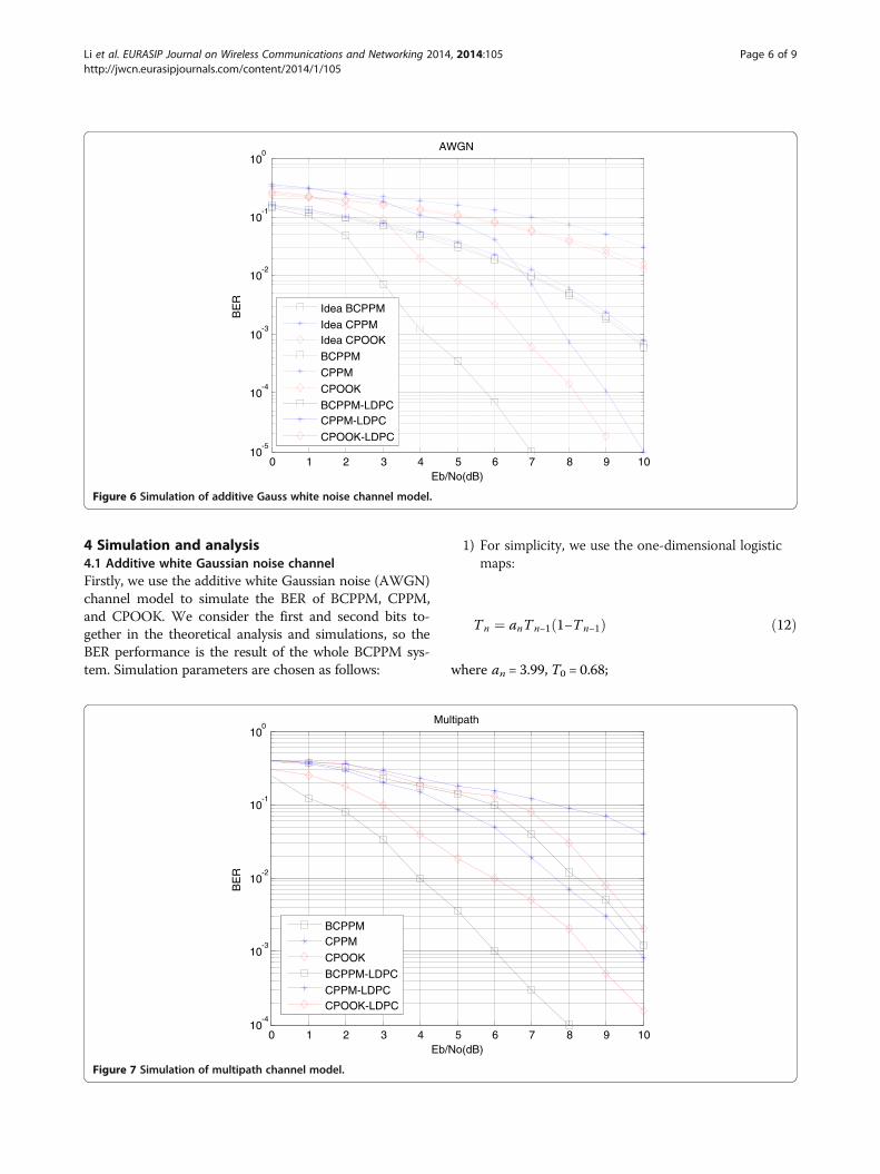
4 Simulation and analysis4.1 Additive white Gaussian noise channelFirstly, we use the additive white Gaussian noise (AWGN)channel model to simulate the BER of BCPPM, CPPM,and CPOOK. We consider the first and second bits to-gether in the theoretical analysis and simulations, so theBER performance is the result of the whole BCPPM sys-tem. Simulation parameters are chosen as follows:
1) For simplicity, we use the one-dimensional logisticmaps:
Tn ¼ anTn−1 1−Tn−1ð Þ ð12Þ
where an = 3.99, T0 = 0.68;
0 1 2 3 4 5 6 7 8 9 1010
-5
10-4
10-3
10-2
10-1
100
Eb/No(dB)
BE
R
AWGN
Idea BCPPM
Idea CPPMIdea CPOOK
BCPPM
CPPM
CPOOK
BCPPM-LDPCCPPM-LDPC
CPOOK-LDPC
Figure 6 Simulation of additive Gauss white noise channel model.
0 1 2 3 4 5 6 7 8 9 1010
-4
10-3
10-2
10-1
100
Eb/No(dB)
BE
R
Multipath
BCPPMCPPM
CPOOK
BCPPM-LDPC
CPPM-LDPCCPOOK-LDPC
Figure 7 Simulation of multipath channel model.
Li et al. EURASIP Journal on Wireless Communications and Networking 2014, 2014:105 Page 6 of 9http://jwcn.eurasipjournals.com/content/2014/1/105
2) The (255,175) cyclic LDPC has been described insection 3.2. We can figure out the system rate is 35
51when using the LDPC code.
As shown in Figure 6, we get nine BER curves. They arethe BCPPM, CPPM, and CPOOK systems in ideal condi-tion; the BCPPM, CPPM, and CPOOK system simulationswithout LDPC; and the BCPPM, CPPM, and CPOOK
simulations with LDPC. From the figure, we can see thatthe simulation results of BCPPM and CPOOK match theideal curves well in the case of non-ideal timing becausethe structure of these systems can overcome the errorpropagation phenomenon. Furthermore, BCPPM has thelower BER compared with CPPM and CPOOK. Becauseeach bit signal needs to transmit an extra synchronizationpulse in CPOOK, the efficiency of the transmitter is
0 1 2 3 4 5 6 7 8 9 1010
-4
10-3
10-2
10-1
100
Eb/No(dB)
BE
R
Multiuser
BCPPMCPPM
CPOOK
BCPPM-LDPC
CPPM-LDPCCPOOK-LDPC
Figure 8 Simulation of multiple-access model.
0 1 2 3 4 5 6 7 8 9 1010
-4
10-3
10-2
10-1
100
Eb/No(dB)
BE
R
Multipath & Multiuser
BCPPM
CPPM
CPOOKBCPPM-LDPC
CPPM-LDPC
CPOOK-LDPC
Figure 9 Simulation of multipath and multiple-access model.
Li et al. EURASIP Journal on Wireless Communications and Networking 2014, 2014:105 Page 7 of 9http://jwcn.eurasipjournals.com/content/2014/1/105

reduced. It is clear that the BER of all systems have greatlydecreased after using cyclic LDPC.
4.2 Multipath channelHere, we simulate the multipath channel model for BCPPM,CPPM, and CPOOK. For simplicity, the channel modelis a two-path channel. The simulation parameters arechosen as follows:
1) Gain of the path 1 is α1 = 0.8 and path 2 is α2 = 0.6;2) The path delays are τ1 = 0 and τ2 = 2 respectively;3) The rest are same with section 4.1.
From the simulation results in Figure 7, we find thatBCPPM has stronger multipath tolerance than CPPMand CPOOK. The reason is that the status informationof chaotic system is completely contained in the timeintervals of the pulses with the same shape. The distor-tion caused by the filter and the channel will only des-troy the shape of pulses, and not affect the intervalsbetween them.
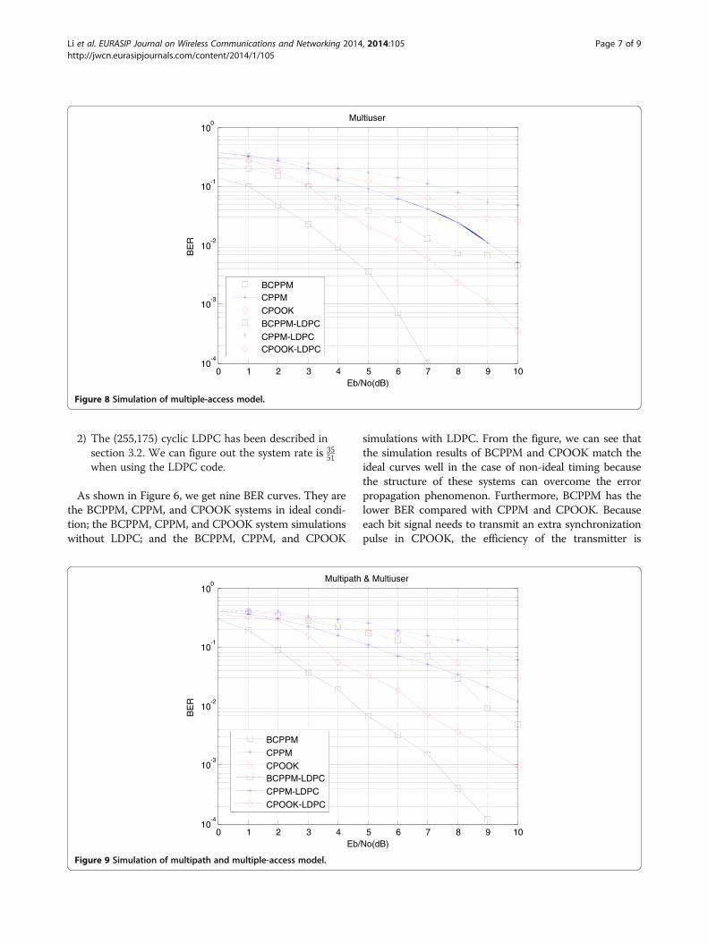
4.3 Multiuser modelIn BCPPM, CPPM, and CPOOK, multiuser communica-tion means assigning different initial values to each userfor the chaotic maps, as we have discussed in section2.3. In this section, we simulate the multiuser model forBCPPM, CPPM, and CPOOK. For simplicity, there aretwo users in this model and the parameters are chosenas follows:
1) Initial value for the chaotic map of user 1 is x 1ð Þ0 ¼ 0:68,
the value of user 2 is x 2ð Þ0 ¼ 0:78;
2) The rest are same with section 4.1.
The simulation results are shown in Figure 8. The figureshows that though the BCPPM system multiple accessmode is simple, it still has low BER performance whenusing the LDPC codes. That is because the synchronizationof the CPRG is between the transmitter and the receiver.Every user's receiver will be kept locked outside its timewindows. If the pulses of different users are outputs in dif-ferent time windows, there will be no multiuser interfer-ence from each other.
4.4 Multipath channel and multiuser modelFinally, we compare the performance of BCPPM, CPPM,and CPOOK in the multipath channel which has twousers. The simulation parameters are same with those insection 4.2. and section 4.3.From the simulation results, we get four BER curves as
before, as shown in Figure 9. It shows that, consideringcomplex communications background of the multipath
and multiuser, the BCPPM system still has a good com-munication performance.
5 ConclusionIn this paper, we proposed a BCPPM communication sys-tem, described the structure of transmitter and receiver,and then discussed the possibility of combining cyclicLDPC code with the system. The BCPPM system has theadvantage of high security, insensitivity to channel distor-tion and simplicity of deploying in multiuser communica-tion. The simulation results show that BCPPM system hasa lower BER compared with the CPPM and CPOOK sys-tems. Besides, the use of cyclic LDPC codes is more con-ductive for the hardware implementation and has betterBER performance.
Competing interestsThe authors declare that they have no competing interests.
AcknowledgementsThis work was supported by the National Natural Science Foundation of China(Grant No. U1304523), the Young Scientists Fund of the National Natural ScienceFoundation of China (Grant No. 11105042) and the Henan Provincial Departmentof Education Science and Technology Research key project (No.13A510330).
Author details1School of Electrical Engineering and Automation, Henan PolytechnicUniversity, Jiaozuo 454000, China. 2School of Engineering and InformationTechnology, Charles Darwin University, Darwin 0909, Australia.
Received: 4 December 2013 Accepted: 12 June 2014Published: 22 June 2014
References1. YS Shen, FB Ueng, LD Jeng, A new time-hopping/direct-sequence biorthogonal
PPM UWB communication system. EURASIP J. Wirel. Commun. Netw.149, 1–11 (2011)
2. LC Tran, A Mertins, TA Wysocki, Unitary differential space-time-frequencycodes for MB-OFDM UWB wireless communications. IEEE Trans. Wirel.Commun. 12(2), 862–876 (2013)
3. LS Jin, Y Zhang, LJ Li, One-to-many chaotic synchronization with applicationin wireless sensor network. IEEE Commun. Lett. 17(9), 1782–1785 (2013)
4. H Yang, GP Jiang, Reference-modulated DCSK: a novel chaotic communicationscheme. IEEE Trans. Circuits Syst. II Expr. Briefs 60(4), 232–236 (2013)
5. M Sushchik, N Rulkov, L Larson, L Tsimring, H Abarbanel, K Yao, A Volkovskii,Chaotic pulse position modulation: a robust method of communicationwith chaos. IEEE Commun. Lett. 4(4), 128–130 (2000)
6. N Rulkov, M Sushchik, L Tsimring, A Volkovskii, Digital communicationusing chaotic-pulse-position modulation. IEEE Trans. Circuits Syst.12(48), 1436–1444 (2001)
7. H Torikai, T Saito, W Schwarz, Multiplex communication scheme based onsynchronization via multiplex pulse-trains, in Proceedings of the 1998 IEEEInternational Symposium on Circuits and Systems (Monterey, CA, USA, 1998),pp. 554–557
8. H Yang, GP Jiang, P Deng, Chaotic pulse On-off-keying modulation schemefor ultra-wide bandwidth communications. J. Electron. Inform. Technol.29(3), 677–680 (2007)
9. H Yang, GP Jiang, A modified, chaotic pulse position modulation schemefor ultra-wide bandwidth communication. J. Nanjing Univ. Posts Telecommun.26(2), 47–50 (2006)
10. RG Gallager, Low-density parity-check codes. IRE Trans. Inform. Theor. 8(1),21–28 (1962)
11. GH Zhang, R Sun, XM Wang, Several explicit constructions for (3, L) QC-LDPCcodes with girth at least eight. IEEE Commun. Lett. 17(9), 1822–1825 (2013)
12. B Rong, YY Wu, G Gagnon, Multi-layer iterative LDPC decoding for broadbandwireless access networks: a recursive shortening algorithm. IEEE Trans. Wirel.Commun. 12(3), 1320–1327 (2013)
Li et al. EURASIP Journal on Wireless Communications and Networking 2014, 2014:105 Page 8 of 9http://jwcn.eurasipjournals.com/content/2014/1/105

13. SX Li, SH Hu, T Feng, GN Ge, The weight distribution of a class of cycliccodes related to Hermitian forms graphs. IEEE Trans. Inf. Theory 59(5),3064–3067 (2013)
14. DJC Mackay, Good error-correcting codes based on very spares matrices.IEEE Trans. Inf. Theor. 45, 399–431 (1999)
15. EB Li, D Declercq, K Gunnam, Trellis-based extended min-sum algorithm fornon-binary LDPC codes and its hardware structure. IEEE Trans. Commun.61(7), 2600–2611 (2013)
doi:10.1186/1687-1499-2014-105Cite this article as: Li et al.: Bipolar chaotic pulse position modulationcommunication system based on cyclic LDPC. EURASIP Journal on WirelessCommunications and Networking 2014 2014:105.
Submit your manuscript to a journal and benefi t from:
7 Convenient online submission
7 Rigorous peer review
7 Immediate publication on acceptance
7 Open access: articles freely available online
7 High visibility within the fi eld
7 Retaining the copyright to your article
Submit your next manuscript at 7 springeropen.com
Li et al. EURASIP Journal on Wireless Communications and Networking 2014, 2014:105 Page 9 of 9http://jwcn.eurasipjournals.com/content/2014/1/105