charging and ignition systems - indianmcinfo and ignition systems 1 figure 1—a simple block...
TRANSCRIPT

Study Unit
Charging andIgnition Systems
By
Ed Abdo

This study unit is the second of three study units devoted to motorcycle and ATV electricalsystems. In the previous study unit, you learned about the basics of electricity, where electricitycomes from, and how to measure it. In this study unit, you’ll learn how to apply this electricaltheory to understand motorcycle and ATV charging and other related electrical systems. We’llbegin by describing the basics of a charging system. Next, we’ll take a closer look at each of thecomponents in the charging system and show you how they operate. After we’ve discussed eachof the components, we’ll review the overall operation of the charging system and tell you how tomaintain and troubleshoot charging systems. Finally, we’ll take a look at some of the otherelectrical circuits found on motorcycles and ATVs.
When you complete this study unit, you’ll be able to
� Explain why motorcycles and ATVs use charging systems
� Describe the theory behind a basic charging system
� Visually identify the different types of charging systems found on motorcycles and ATVsfrom the wiring diagrams
� Describe how alternators generate AC power
� Describe how a charging system changes alternating current into direct current
� Explain the electrical system of motorcycles and ATVs that don’t use a battery
� List the steps required for maintenance and minor troubleshooting of a charging system
� Read block diagrams for various DC electrical system circuits
Preview
iii

New Table of ContentsINTRODUCTION . . . . . . . . . . . . . . . . . . . . . . . . . . . . . 1Charging System OverviewCharging System Components
ALTERNATORS . . . . . . . . . . . . . . . . . . . . . . . . . . . . . . 3Permanent-Magnet AlternatorsExcited-Field Electromagnet AlternatorsAlternator Maintenance
REGULATORS AND RECTIFIERS . . . . . . . . . . . . . . . . . . . . . . 7RectifiersVoltage RegulatorsRegulator/Rectifier Inspection
MOTORCYCLE AND ATV BATTERIES . . . . . . . . . . . . . . . . . . . 12Conventional BatteriesHow Lead/Acid Batteries WorkMaintenance-Free BatteriesInspecting BatteriesMotorcycles and ATVs Without Batteries
CHARGING SYSTEM OPERATION . . . . . . . . . . . . . . . . . . . . 19Types of Charging SystemsHalf-Wave Charging SystemFull-Wave Charging System3-Phase Permanent-Magnet Charging System3-Phase Electromagnet Charging SystemCharging Systems Summary
MAINTAINING AND TROUBLESHOOTING CHARGING SYSTEMS . . . . 27Hand Tools for Electrical WorkBattery MaintenanceRectifiersVoltage RegulatorsAlternator Inspection and Testing
v
Contents

DC ELECTRICAL SYSTEM CIRCUITS. . . . . . . . . . . . . . . . . . . . 36Light BulbsSwitchesHeadlight CircuitsTurn Signal/Hazard Relay CircuitsBrake-Light CircuitsHorn CircuitsNeutral-Light CircuitsWarning Lights
ROAD TEST ANSWERS . . . . . . . . . . . . . . . . . . . . . . . . . . 45
EXAMINATION . . . . . . . . . . . . . . . . . . . . . . . . . . . . . 47
vi Contents

INTRODUCTIONA charging system is necessary in any motorcycle or ATV which has abattery for powering electrical components. As we mentioned in theprevious study unit on basic electricity fundamentals, the first step tounderstanding electrical systems and how they work is to start withthe basics.
To understand how a charging system works, you must first under-stand what a charging system does. Then, you need to know thecomponents that make up the charging system and how they work.
Charging System OverviewThe purpose of a charging system is to replenish the power in a batteryas it’s used. An alternator provides the electrical power source for thecharging system (Figure 1). The alternator provides an alternatingcurrent (AC) output. In order to convert the AC output of the alterna-tor to direct current (DC), which is needed by the battery, a rectifier isused. The rectifier converts the AC (which you’ll remember alternatelyflows in one direction, then in the other direction) into DC, whichflows in only one direction. This process is known as rectification.The voltage from the charging system to the battery is maintainedwithin certain limits by a voltage regulator. By controlling the outputof the charging system, the regulator prevents undercharging orovercharging the battery.
Some racing machines use what is known as a “total loss” electricalsystem. This means that the electrical system doesn’t have a chargingsystem. The battery has enough power to complete the race withoutrecharging. When the battery becomes discharged, the machine willno longer operate and the battery must be recharged using an
Charging and Ignition Systems
1
FIGURE 1—A simple blockdiagram of a chargingsystem is shown here.

external battery charger. This study unit, however, will focus onmachines having charging systems.
Charging System ComponentsFrom small 50cc ATVs to large 1500cc touring motorcycles, allcharging systems have the same common basic components as shownin Figure 1. These components may have different designs in variousmotorcycles and ATVs, but still provide the same functions in thecharging system.
AlternatorAn alternator is a generator that produces an AC voltage. Thealternator is driven by the rotation of the engine crankshaft. Thus, itonly produces an electrical output when the engine is running. Theoutput from the alternator varies with the speed of the engine.
RectifierA rectifier converts the AC from the alternator into DC that is used bythe battery. There are basically two types of rectifiers: half wave andfull wave, which will be discussed later in this study unit. The rectifieruses a diode or diodes to convert the AC into DC by allowing currentflow in one direction only.
Voltage RegulatorA voltage regulator may be a separate device or it may be containedwith the rectifier as a single unit. There are many types of regulators.The newer solid-state types of regulators use thyristors (SCRs) andZener diodes, which provide a current limiting function to controlbattery charging.
BatteryA battery is an electrical storage device which supplies DC power forthe motorcycle or ATV electrical systems. As the battery is dischargedfrom use, the charging system charges the battery as needed.
In summary, the alternator generates AC voltage. The rectifierchanges the AC into DC. The battery stores the DC voltage and thevoltage regulator controls the voltage being sent to the battery. This isbasically what a charging system does in a motorcycle or ATV (or anautomobile, or lawn and garden tractor for that matter!).
Now, let’s begin by looking more closely at each of the componentsthat make up the charging system. After we’ve learned more about
2 Charging and Ignition Systems
each of these components, we’ll look at the charging system operationin more detail.
ALTERNATORSDepending on the manufacturer, there are many different terms usedfor an alternator including generator, dynamo, and magneto. For thepurpose of this study unit, we’ll simply refer to them as alternators.
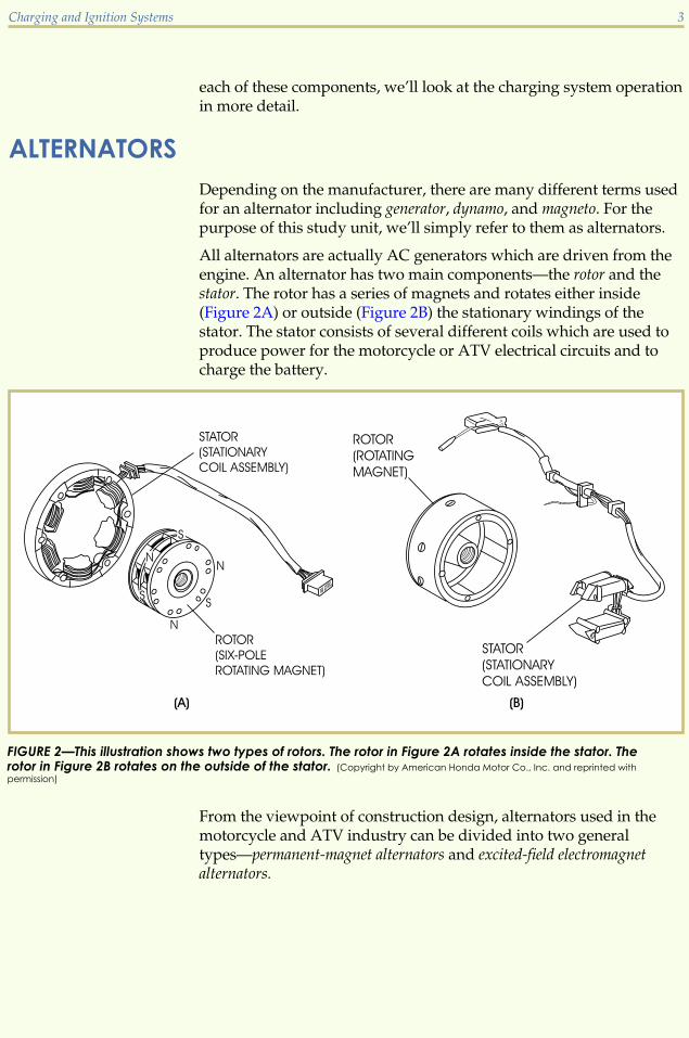
All alternators are actually AC generators which are driven from theengine. An alternator has two main components—the rotor and thestator. The rotor has a series of magnets and rotates either inside(Figure 2A) or outside (Figure 2B) the stationary windings of thestator. The stator consists of several different coils which are used toproduce power for the motorcycle or ATV electrical circuits and tocharge the battery.
From the viewpoint of construction design, alternators used in themotorcycle and ATV industry can be divided into two generaltypes—permanent-magnet alternators and excited-field electromagnetalternators.
Charging and Ignition Systems 3
FIGURE 2—This illustration shows two types of rotors. The rotor in Figure 2A rotates inside the stator. Therotor in Figure 2B rotates on the outside of the stator. (Copyright by American Honda Motor Co., Inc. and reprinted with
permission)

Permanent-Magnet AlternatorsThe permanent-magnet alternator is the most commonly used type ofAC generating system found on motorcycles and ATVs. Permanentmagnets are incorporated into the flywheel on the outside of the rotoras illustrated in Figure 2B. With this design, the flywheel is fitted ontoa tapered crankshaft and is assured positioning by the use of aWoodruff key.
The inner rotor permanent magnet pictured in Figure 2A isn’tcurrently in use because of the high cost of the special permanentmagnet that’s required.
Excited-Field Electromagnet AlternatorsExcited-field electromagnet alternators don’t use a permanentmagnet. Instead, they have a field coil which is energized with DCcurrent. The field coil becomes a powerful magnet and magnetizesthe rotor. Power is generated as the rotor spins past the stator.Excited-field electromagnets are located in different outside areas ofthe engine to help keep them cool. The rotor speed is generallymultiplied by gears or chains to increase the rotor’s speed of rotation.
The excited-field alternator is potentially the most powerful ACgenerator available because of the high amount of magnetism that itcan create. This type of alternator is primarily used on largerdisplacement motorcycles. There are two types of excited-fieldelectromagnet alternators (Figure 3).
� The brush-type excited-field coil has the field coil placed withinthe rotor. Current flows through the brushes to the field-coil sliprings. When current is applied, the rotor is inducedelectromagnetically and becomes a very strong magnet.
� The brushless-type excited-field coil eliminates the maintenancefactor of the excited-field coil design by placing a two-piecerotor around the inner field coil. When the field coil isenergized, the magnetic field magnetizes the rotor core. Therotation of the magnetized core acts on the stator coils toproduce AC current.
4 Charging and Ignition Systems

Alternator MaintenanceProblems seldom occur with alternators because they have fewmoving parts. Servicing is generally not required except onbrush-type excited-field alternators. If a problem does occur on analternator, the problem may be due to the stator coil. Stator coils aremanufactured under very strict quality control and usually don’t failwhen they are new, but as a technician, you still need to be aware ofpossible coil failures such as the following.
Open stator wire. If the stator wire is open, there is no AC output. Inthis case, an ohmmeter will indicate no continuity (infinite resistance)between the terminals.
Charging and Ignition Systems 5
FIGURE 3—Brush-Type andBrushless-Type Excited-FieldCoil Systems (Copyright by
American Honda Motor Co., Inc.
and reprinted with permission)

Shorted circuit. Diagnosis of a shorted circuit is a bit moredifficult. The symptom may simply be poor AC output performanceor low AC output when the engine is hot. Vibration or shock can bethe cause of such problems.
When checking the continuity of a stator, remember to isolate thestator from the rest of the electrical system.
Road Test 1
At the end of each section of Charging and Ignition Systems, you’ll be asked to check yourunderstanding of what you’ve just read by completing a “Road Test.” Writing theanswers to these questions will help you review what you’ve learned so far. Pleasecomplete Road Test 1 now.
1. What is used to produce AC in a motorcycle or ATV charging system?
2. Which type of alternator is the most popular system found on motorcycles and ATVs?
3. What are the two main components found in an alternator?
4. What are two problems that can occur in a stator coil?
5. Which type of alternator does not use permanent magnets?
6. Explain the difference between a permanent-magnet and an excited-field coil system.
7. On a permanent-magnet alternator, where are the magnets located?
8. True or False? It’s unusual to see problems occur with the alternator portion of a chargingsystem because it contains very few moving parts.
Check your answers with those on page 45.
6 Charging and Ignition Systems

REGULATORS AND RECTIFIERSAlthough they are two separate components, regulators and rectifiersare normally integrated into the same housing on modernmotorcycles or ATVs (Figure 4). A simplified schematic of a chargingsystem is shown in Figure 5. Note the dotted lines surrounding theregulator/rectifier. Inside the lines you can see six diodes and threeSCRs. The diodes make up the rectifier while the SCRs are used aspart of the regulator. We’ll discuss the rectifier and regulatorseparately even though they’re combined as one unit.
Charging and Ignition Systems 7
FIGURE 4—This is a pictureof a typical regulator/rectifier. The cooling finshelp to remove the heatproduced from theregulator when it sendscurrent back to ground.
FIGURE 5—ChargingSystem SchematicDiagram (Copyright by American
Honda Motor Co., Inc. and reprinted
with permission)

RectifiersThe purpose of a rectifier is to change the AC that’s produced by thealternator into DC to charge the battery. A rectifier consists of as fewas one or as many as six diodes, depending on the charging system.Remember that the diode serves as a one-way electrical valve.
The basic principle behind a rectifier’s function is that it allowscurrent to pass through in only one direction—kind of like a one-waygate. Because alternating current is continually reversing direction,the rectifier must change it to direct current so that it can be used bythe battery, which is a DC device. A single diode rectifier wired inseries into a circuit will block half of the AC current flowing into itand allow the other half of the current to flow to the battery as seen inFigure 6. This is known as half-wave rectification.
In order to allow all of the current produced by the alternator to reachthe battery, more diodes are used. Four diodes can be used to allowboth waves of the AC current to pass as shown in Figure 7. Thisallows all of the current created by the alternator to be converted intoDC. When four diodes are used, it’s known as full-wave rectification.We’ll discuss these systems in more detail in a later section of thisstudy unit. When rectifiers are defective, they can’t be repaired andmust be replaced. You’ll also learn how to test rectifiers later.
8 Charging and Ignition Systems
FIGURE 6—This simplifiedschematic shows ahalf-wave rectifier whichblocks one-half of the ACwaveform. (Copyright by American
Honda Motor Co., Inc. and reprinted
with permission)

Voltage RegulatorsThe purpose of the voltage regulator is to control the voltage toprevent undercharging or overcharging the battery. There are twotypes of voltage regulators—mechanical and electronic.
Mechanical Voltage RegulatorsThe mechanical voltage regulator was widely used on motorcyclesuntil the mid-1970s, but now is all but extinct. In the mechanicalvoltage regulator, the alternator charges the battery through theadjustable contact points of the regulator (Figure 8). When thealternator output reaches approximately 15 volts on a 12-volt system,the relay coil is energized and pulls the armature down to open thecontact points. Therefore, the regulator acts like a switch that opens orcloses the circuit to control battery charging.
Charging and Ignition Systems 9
FIGURE 7—By using fourdiodes, both the upper andlower halves of thealternating currentwaveform are used andwe have a full-waverectification system. (Copyright
by American Honda Motor Co., Inc.
and reprinted with permission)
FIGURE 8—This figure showsan internal view of amechanical voltageregulator. This type ofregulator is no longerbeing used onmotorcycles or ATVs. (Copyright
by American Honda Motor Co., Inc.
and reprinted with permission)

Electronic Voltage RegulatorsElectronic voltage regulators are commonly used on motorcycles andATVs today. Electronic regulators contain no moving parts and neverneed to be adjusted. There are too many types of electronic regulatorsto try to discuss each and every type. Most electronic regulators, orcurrent limiters as they are sometimes called, have a solid-state,transistorized arrangement of electronic devices, such as thyristorsand Zener diodes. Because electronic voltage regulators are sealedunits, they cannot be repaired. If tested and found to be defective, theunit must be replaced.
One disadvantage of having both the regulator and the rectifierassembled as one complete unit is that if either the regulator orrectifier portion fails, the entire unit must be replaced.
Regulator/Rectifier InspectionAs we’ve mentioned, electronic voltage regulators and rectifiers haveno internal moving parts and must be replaced if found to bedefective. The main symptoms of a faulty voltage regulator are thefollowing:
� The battery discharges.
� The battery becomes overcharged.
� The lights in the electrical system burn out quickly.
In most cases, to inspect a voltage regulator, you simply run theengine at the manufacturer’s recommended engine speed and checkfor DC current at the battery. If the system is overcharging, theregulator is at fault and will require replacement. If the chargingsystem is undercharging and all other charging system componentshave been proven to be in proper working order, the regulator isprobably at fault.
Rectifiers are relatively easy to test. An ohmmeter is used to testrectifiers as shown in Figure 9. Simply connect the ohmmeter to theends of each of the diodes and check the resistance in both directions.The resistance should be low in one direction and very high in theopposite direction. The specification should be given in theappropriate service manual. A general guideline for testing mostdiodes is to have 5–40 ohms of resistance in the forward bias direction(where current is allowed to pass) and infinite resistance in thereverse bias direction (where current isn’t allowed to pass).
To test the rectifier in Figure 9, attach the black probe of theohmmeter to the ground side of the rectifier (E) and the red probe toP1, P2, and P3. Record your measurements. Then swap the meterleads and take the three resistance readings again. You have nowmeasured the ground side of the rectifier.
10 Charging and Ignition Systems

You can now test the battery side of the rectifier by attaching themeter probes to the battery (B) side of the rectifier and test the diodesin the same manner. When you have completed testing, you shouldhave 12 readings consisting of forward and reverse-biasmeasurements for each of the six diodes.
Charging and Ignition Systems 11
FIGURE 9—This illustrationdemonstrates how totest the diodes in arectifier. (Courtesy Kawasaki
Motor Corp.,U.S.A.)

Road Test 2
1. True or False? Electronic voltage regulators are adjustable.
2. Generally speaking, how many ohms of resistance should a diode have in theforward-bias direction?
3. What are the three main symptoms of a faulty voltage regulator?
4. Generally speaking, how much resistance should a diode have in the reverse-biasdirection?
5. True or False? Rectifiers and voltage regulators are contained as one complete unit onsome motorcycles and ATVs.
6. True or False? A system that allows all of the AC current from the alternator to be rectifiedinto DC current is called full-wave rectification.
7. What type of voltage regulator is adjustable?
8. What’s another term used to describe a voltage regulator?
Check your answers with those on page 45.
MOTORCYCLE AND ATV BATTERIESMotorcycle and ATV batteries are called lead-acid batteries. They’realso referred to as storage batteries because of their ability to storeelectricity. Most modern motorcycles and ATVs use 12-volt batteries.
Conventional BatteriesA conventional wet-cell motorcycle or ATV battery consists of a seriesof cells (Figure 10). Each cell has positive and negative metal platesand is capable of storing approximately 2 volts of electricity. Theplates fit into a casing that’s filled with an electrolyte solution(a mixture of distilled water and sulfuric acid). The battery produceselectricity from a chemical change that takes place between thesepositive and negative plates in the electrolyte solution (Figure
12 Charging and Ignition Systems

11). The distilled water in the acid solution has the tendency toevaporate in a conventional battery. When it does, replenish thebattery with distilled water only! If you use any other liquid, you’llshorten the life of the battery. Distilled water has had the impuritiesremoved, which prevents contamination of the sulfuric acid and thelead plates in the battery.
Charging and Ignition Systems 13
FIGURE 10—A TypicalWet-Cell Battery in anExploded View

How Lead/Acid Batteries WorkWhen you charge a lead-acid battery, electrolysis breaks the waterdown into its components—hydrogen and oxygen gas. Because of thegeneration of these gases, you must remove the filler plugs whilecharging the battery (Figure 12). Conventional batteries have a vent,usually routed into a tube, to remove the gases produced duringnormal use.
When excess current is supplied to the battery, the battery is said tobe overcharged. When the battery is overcharged, gas is emitted fromthe plates, and electrolyte temperature increases. This increase in heatcauses a rapid loss of water from the battery electrolyte if continued
14 Charging and Ignition Systems
FIGURE 11—The plates in abattery are separatedfrom each other. (Copyright
by American Honda Motor Co., Inc.
and reprinted with permission)
FIGURE 12—As a batteryis charged, it causes achemical reaction thatwill pressurize thebattery. Be sure toremove the battery ventcaps when charging abattery. (Copyright by American
Honda Motor Co., Inc. and reprinted
with permission)

over a long period of time. The loss of water and increased heatdrastically reduces the life of the battery and, if left uncorrected, willdamage the battery beyond repair.
Because a battery is constantly subjected to charging and dischargingcycles, the water in the electrolyte is slowly boiled off during normaluse. When the water is evaporated to the point where the platesbecome exposed, a white crystalline deposit (lead sulfate) forms. Thisprocess is known as sulfation. This damages the battery and shortensthe battery life. Sulfation can occur not only when the electrolyte levelis low, but also when the battery is discharged for long periods oftime.
Remember, as the electrolyte level goes down when the water in thebattery evaporates, replenish the battery with distilled water only.
Maintenance-Free BatteriesMaintenance-free batteries are very similar in design to conventionalbatteries. The difference is that the positive and negative lead platesin the maintenance-free battery allow for a chemical reactioninternally that produces water as it’s needed. Therefore, you don’tneed to add water to a maintenance-free battery.
Unlike the conventional battery, maintenance-free batteries don’thave a vent to allow for the escape of excess gases. Instead, they use asafety valve that’s designed to open when extreme gas pressures areproduced. The safety valve closes and seals the battery when theinternal pressure returns to normal. Figure 13 shows a cutawaydrawing of a typical maintenance-free battery and its internalcomponents.
Charging and Ignition Systems 15
FIGURE 13—The parts ofa maintenance-freebattery are shown in thiscutaway drawing. (Copyright
by American Honda Motor Co., Inc.
and reprinted with permission)

Inspecting BatteriesBefore doing any testing, you should always visually inspect thebattery. If there are cracks in the casing, broken terminals, or othersigns of severe damage, such as heavy white lead sulfate on theinternal plates, the battery should be replaced.
Next, check the battery cables and ensure they have good contactwith the battery terminals. If the cables or terminals are corroded orloose, be sure to clean and tighten the connection. A bad batteryconnection can cause very high resistance, which will interfere withthe flow of electrical current. This can cause many different problemsin the electrical system. Clean the battery cables and terminals with awire brush. A smear of dielectric grease on the cables and terminalswill help prevent corrosion.
The electrolyte in a battery is very caustic. The condition of a batteryis determined by the specific gravity of the electrolyte. Specific gravityis measured by using a hydrometer (Figure 14), which is available frommost automotive parts stores. When a battery is new or fully charged,you should get a specific gravity reading of 1.280 to 1.320 (dependingon air temperature). As the battery is discharged, this reading willdecrease.
16 Charging and Ignition Systems
FIGURE 14—A hydro-meter measures thespecific gravity of theelectrolyte in thebattery. (Copyright by American
Honda Motor Co., Inc. and reprinted
with permission)

A battery provides direct current for operating the motorcycle orATV. One way of knowing the amount of current that can be drawnout of a battery is to know its ampere-hour capacity. For example, a12-amp/hour battery will discharge fully if one amp of current isdrawn out continuously for a 12-hour period.
Batteries are rated in ampere-hours. The larger the ampere-hournumber, the stronger the battery. The voltage does not change inrelation to ampere-hours of the battery. The ampere-hour rating of abattery is often indicated on its case. For example, a 12-amp/hourbattery would have “12A” printed on the case.
Be very careful when working with a battery. Always wear safetyglasses when working around batteries. Battery acid will destroyclothing, paint, etc., and could also cause severe burns if it gets onyour skin. If you accidentally spill some battery acid, the spill shouldbe washed quickly using water and baking soda to help neutralize theacid.
One last note about batteries. Always use a fully-charged batterywhen performing any charging system electrical tests to prevent falsemeter readings.
Motorcycles and ATVs Without BatteriesMany of the smaller motorcycles and ATVs that have lightingsystems and other electrical circuitry don’t have batteries in theirelectrical systems. These machines use AC power to generateelectricity for their electrical components (Figure 15). The alternatorgenerates the electricity, which is controlled by an AC regulator. Forcomponents that use transistors which require DC current, a smallrectifier (DC power unit) is used.
AC RegulatorsTo provide a stable current without the use of a battery, a high-outputalternator that can generate sufficient current at low rpm must beused. If the alternator output is allowed to rise as the engine rpm isincreased, the excessive current will burn out the lighting systembulbs. To prevent this from occurring, the AC regulator maintains apredetermined output voltage by shorting any excessive current toground.
Charging and Ignition Systems 17
FIGURE 15—This illustrationshows a block diagram ofa motorcycle or ATVelectrical system thatdoesn’t use a battery.

An example of a type of AC voltage regulator is illustrated inFigure 16. The current from the alternator flows directly to the loads(lights, electric starters, etc.) at voltage levels lower than the voltageregulator value. As the engine rpm rises (increasing the AC voltage),the regulator directs the current to the thyristor, which in turn shortsthe alternator output to ground. In this way, the voltage regulatorcuts off the excess voltage to maintain a constant voltage output.
DC Voltage UnitsAlthough most electrical components use AC power in electricalsystems without a battery, there are a few systems that require DCcurrent to operate. A compact DC voltage unit rectifies the AC intoDC for these specific applications. The DC voltage unit will normallyconsist of a simple diode to change the AC power to DC.
18 Charging and Ignition Systems
FIGURE 16—Thisillustration shows asimplified schematicdiagram of an ACvoltage regulator. (Copyright
by American Honda Motor Co., Inc.
and reprinted with permission)

Road Test 3
1. What is the solution called that’s used in motorcycle and ATV batteries?
2. _______ current is used to charge a battery.
3. What is a battery hydrometer used for?
4. What is the name of the white crystalline material that develops on exposed batteryplates?
5. What does “14A” stamped on a battery mean?
6. True or False? A motorcycle or ATV that doesn’t use a battery can’t use any DC-poweredelectrical components.
7. With a sulfuric acid spill, _______ can be used to neutralize the acid.
8. What are some of the items to look for when visually inspecting a battery?
9. What type of battery doesn’t require that you add water to it?
10. What should be put back into a conventional battery after the plates have been exposed?
Check your answers with those on page 45.
CHARGING SYSTEM OPERATIONNow that you know the basic components of a motorcycle and ATVcharging system, let’s see how these components work together as asystem. Later in this lesson, you’ll learn how to perform variouscharging circuit tests. But first, let’s look at an example of a completeschematic for a Kawasaki GPZ 500S, as shown in the Wiring Diagramincluded in this shipment. Note that all wires are color-coded andthat a color-code chart is shown in the lower right corner of theschematic. At the bottom of the schematic, notice that the connectionsare shown for each position of the switches.
The schematic may seem quite complex at first, but if you break downthe individual electrical system that you’re working with in a
Charging and Ignition Systems 19

schematic, it becomes much easier to read and understand. You canbreak down a schematic by drawing a “block diagram” of the systemas seen in Figure 17. Use this figure to follow along as we talk aboutthe operation of a basic charging system.
Find the alternator on the block diagram. The alternator produceselectricity in the form of alternating current when the engine isrunning. Now locate the alternator on the actual schematic. As werefer to each of the charging system components on the blockdiagram, locate them on the actual schematic as well to see how theblock diagram was derived from the schematic.
Notice the three stator leads connected to the alternator. Currentflows through these leads, which are color-coded and labeled Y(yellow). These wires carry AC current from the alternator to theregulator/rectifier as the alternator rotor spins past the stator windings.The AC current enters the rectifier and is changed to direct current,which leaves the rectifier through the W (white) wire. This white wireprovides direct current to the battery for charging. The current in theBR (brown) wire travels from the ignition switch to the loads (lights,etc.) and to the regulator portion of the regulator/rectifier. Theregulator is connected to the common ground system by the BK/Y(black with yellow tracer) wire. When the voltage reaches apredetermined level, the voltage regulator routes the excess rectifiedDC current to ground to prevent the battery from being overcharged.
As you can see, by connecting individual components to worktogether as a system, direct current is provided for charging thebattery and supplying power to the lighting system. The alternatingcurrent is changed into direct current by the rectifier. The amount ofcharging voltage is controlled by the voltage regulator. Each
20 Charging and Ignition Systems
FIGURE 17—A blockdiagram of the chargingsystem for the KawasakiGPZ 500S is shown here. Byseparating the differentelectrical componentsfrom the complete wiringschematic, your job ofworking on the electricalsystem will become mucheasier. (Courtesy Kawasaki Motor
Corp., U.S.A.)

component in the charging system must be kept in good workingcondition to allow the charging system to continue to functionproperly. This includes keeping all wiring connections clean andtight-fitting to prevent excessive resistance.
Types of Charging SystemsNow that you understand how a basic charging system operates andcan identify the individual components in a charging system, we’llmove on to a discussion of the various types of charging systems thatare found on motorcycles and ATVs. We’ll begin with the simplestcharging system and then learn about the more complex systems.Remember, all charging systems operate in the same basic fashion;they just have different ways of producing AC current. One way thatcharging systems differ is related to the number of charging coils atthe input. The charging system is also based on the needs of theelectrical system. More electrical components require a larger outputcharging system.
Half-Wave Charging SystemThe half-wave charging system is the simplest charging system. Thischarging system uses only one “grounded” charging coil, and onlyone-half of the AC output is actually used. As shown in Figure 18, thealternator has two pairs of magnets; and it produces two cycles of ACfor each rotation (360 degrees) of the rotor (flywheel).
A single diode is used to rectify the AC output into DC to charge thebattery. When the AC flows through the diode, the negative voltagewave of the AC is cut off and the positive voltage wave is passed tocharge the battery.
This type of charging system has a low output, and its small size isbest suited for very small machines with small electrical loads.Because of its low-output potential, this charging system isn’t usedvery much anymore.
These low-output systems regulate the DC voltage by the use of arelatively simple half-wave regulating system as shown in Figure 19.In this system, the charging current from the alternator is rectified bydiode D1 and charges the battery. When the AC voltage increases asthe engine rpm increases, the AC wave rectified by diode D2 goesthrough the Zener diode (ZD) and allows the gate of the SCR to open.The SCR shorts the AC input from the alternator to ground.Therefore, the half-wave charging system with a voltage regulator iseither fully charging the battery or not charging the battery at all! Thisis the major disadvantage of the half-wave charging system and themain reason that it’s not used much any longer.
Charging and Ignition Systems 21

22 Charging and Ignition Systems
FIGURE 18—A half-wavecharging system uses asingle grounded coil.(Copyright by American Honda Motor
Co., Inc. and reprinted with permission)
FIGURE 19—A VoltageRegulator in a Half-WaveCharging System (Copyright by
American Honda Motor Co., Inc. and
reprinted with permission)

One other type of voltage regulation found on some half-wavecharging systems is known as the “balanced” charging system. In thissystem, the alternator is designed to allow a maximum amount of ACthat won’t overcharge the battery. The proper AC level is maintainedindependent of engine speed. Therefore, the balanced chargingsystem needs no voltage regulator. The complete charging systemconsists of an alternator, a single diode, and a battery.
Full-Wave Charging SystemA full-wave charging system also uses one charging coil similar to thehalf-wave system, but instead uses the full output potential of thecharging coil. Full-wave charging systems are used on somemedium-sized motorcycle and ATV engines. When comparing thissystem to the half-wave charging system, you’ll notice that it’s moreefficient by using all of the alternator potential for charging thebattery.
The full-wave charging system uses four diodes to rectify the ACfrom the alternator into DC (Figure 20). When the AC input voltage ispositive, current flows from the alternator through diode D1, to thebattery, through diode D2, and back to the alternator as shown by thewhite arrows. When the AC input voltage reverses direction, currentflows from the alternator, through diode D3, to the battery, throughdiode D4, and back to the alternator as shown by the black arrows.Operating in this fashion, the AC output of the alternator is convertedinto a full-wave DC waveform.
Charging and Ignition Systems 23
FIGURE 20—This illustrationshows how current flowsthrough a full-waverectifier. (Copyright by American
Honda Motor Co., Inc. and reprinted
with permission)

The voltage regulation system used on a full-wave charging systemnormally has a voltage feedback line (Figure 21). The feedback linetells the voltage regulator when the battery no longer needs charging.The regulator then opens the gates on the SCRs. The SCRs short theAC input from the alternator to ground and cut off the current to thebattery.
3-Phase Permanent-Magnet Charging SystemThe 3-phase permanent-magnet charging system is the most widelyused system on both motorcycles and ATVs because of the largecharging potential to the electrical system. This system usespermanent magnets like the charging systems previously mentioned;however, the 3-phase system uses three charging coils instead of one(Figure 22).
The rectifier in the 3-phase system consists of six diodes and isconnected directly to the 3-phase alternator. The voltage regulationsystem is the same as the full-wave system except that it has theability to change the charging system from 3-phase into a full-wave ora half-wave system as the battery approaches a full charge. This isdone by independently controlling the gates to the three SCRs, whichshort the alternator output to ground. The waveform created by a3-phase charging system more closely approximates a pure DCoutput because of the three AC waves that are produced in a singlerevolution of the alternator’s rotor.
24 Charging and Ignition Systems
FIGURE 21—A VoltageRegulator in a Full-WaveCharging System (Copyright by
American Honda Motor Co., Inc. and
reprinted with permission)

3-Phase Electromagnet Charging SystemThe 3-phase electromagnet charging system is used on many largermotorcycles and on motorcycles that have the alternator in a locationthat’s not directly mounted on the crankshaft. The 3-phaseelectromagnet system differs from the 3-phase permanent-magnetsystem primarily because it uses an electromagnet instead of apermanent magnet in the alternator to produce the input AC(Figure 23).
In the 3-phase electromagnet system, the charging rate is controlledby controlling the strength of the magnetic field in the alternator fieldcoil and, therefore, the output of the alternator. The voltage regulatormonitors the voltage at the battery and controls the base of thetransistor. When the regulator turns the transistor on, the batteryfeeds current through the ignition switch, field coil, and transistor toground. The field coils magnetize the rotor and the alternatorgenerates AC current as the engine rotates. The charging systemwaveform is the same as for the 3-phase permanent-magnet system.
When the charging system reaches a predetermined voltage, thevoltage regulator turns the transistor off and cuts off the current tothe field coil. This removes the magnetic field from the field coil andprevents the charging system from operating.
Charging and Ignition Systems 25
FIGURE 22—This illustrationshows a typical 3-phasepermanent-magnetcharging system. (Copyright by
American Honda Motor Co., Inc. and
reprinted with permission)

Another voltage regulation system used with the 3-phase electro-magnet charging system allows for the field-coil voltage to be alteredto create a stronger or weaker electromagnet. By having more currentpass through the field coil, a stronger electromagnetic field is created.Conversely, having less current pass through the field coil producesa weaker electromagnetic field. In this way, the output from thealternator can be varied rather than simply turned on and off.
Charging Systems SummaryAs you can see, the charging systems used in motorcycles and ATVscan be very simple or somewhat complex. All you need to do is torecognize the type of system that you’re working on. Then youshould know how it regulates the AC and DC current to controlcharging the battery.
26 Charging and Ignition Systems
FIGURE 23—The 3-phaseelectromagnet chargingsystem can easily beidentified by the use of afield coil, as this illustrationshows. (Copyright by American
Honda Motor Co., Inc. and reprinted
with permission)

Road Test 4
1. Which type of charging system uses six diodes to rectify the AC input?
2. True or False? A “balanced” charging system is a type of half-wave charging system.
3. Which type of charging system uses a field coil instead of permanent magnets?
4. Which charging system is the most widely used system found on both motorcycles andATVs?
5. Of all the charging systems discussed, the _______ system is the most simple.
6. True or False? All charging systems operate in the same basic fashion; they just havedifferent ways of producing AC current.
7. The half-wave charging system uses how many charging coils?
8. What is the difference between a half-wave charging system and a full-wave chargingsystem?
Check your answers with those on page 45.
MAINTAINING AND TROUBLESHOOTING CHARGINGSYSTEMS
In the previous sections of this study unit, we’ve briefly discussedhow to inspect the different components of a motorcycle and ATVcharging system. We’re now going to combine that information andexpand on it to help you understand how to maintain andtroubleshoot problems found within the charging systems.
Charging and Ignition Systems 27

Hand Tools for Electrical WorkThe basic hand tools you’ll need for most electrical repairs are asfollows:
� Soldering gun
� Diagonal cutters
� Needle-nose pliers
� Wire stripper/crimping pliers
� Electrical test equipment
Most electrical tests can be performed with a multimeter. Amultimeter is very useful because it’s actually at least four meters inone. To check the electrical components and systems found onmotorcycles and ATVs, a multimeter should have at least thefollowing measuring capabilities:
� DC Amps
� DC Volts
� AC Volts
� Ohms
Battery MaintenanceThe condition of the battery should be your first concern whenworking on the electrical system of a motorcycle or ATV. Alwaysbegin with a thorough visual inspection of the battery as previouslydescribed in this study unit. Also, be sure to check the battery cablesfor corrosion and tightness. If necessary, clean the terminals as wepreviously described and use dielectric grease on the cables toprevent corrosion. Measure the specific gravity of the electrolyteusing a hydrometer. Batteries that are weak or have been out ofservice for a long period of time can be recharged using a batterycharger (Figure 24).
Batteries can be tested for their ability to hold a charge by using abattery load tester (Figure 25). The load tester tests the battery under aheavy electrical load condition while it’s out of the motorcycle orATV.
28 Charging and Ignition Systems

Remember the safety concerns we discussed earlier pertaining tobatteries. Always wear safety glasses and be very careful whenworking around battery acid. Remember that the acid can causeburns and will destroy objects it comes in contact with. Use water andbaking soda to clean up spills. Review the previous information inthis study unit about the inspection, testing, and handling of batteriesif necessary.
Charging and Ignition Systems 29
FIGURE 24—A batterycharger provides DCcurrent to rechargebatteries.
FIGURE 25—The technicianis checking the batteryunder a predeterminedload by pushing the buttonon the tester. This battery issatisfactory because theneedle is in the “good”portion of the meter face.

RectifiersWhen a rectifier is defective, it isn’t repaired—it’s replaced. Todetermine if a rectifier is defective, you can do a couple of simpletests.
The first test requires a 12-volt battery, two wires, and a light bulb.First, remove the rectifier from the circuit and from the motorcycle.Connect a wire from the positive terminal of the battery to the inputside of the rectifier (Figure 26). Connect the other wire from theinsulated part of the light bulb to the output side of the rectifier.Ground the light bulb to the negative battery post. The light bulbshould light. Now, reverse the connection at the rectifier. The bulbshouldn’t light. If the bulb doesn’t light at all, or if it lights when therectifier is reversed, the rectifier is defective and must be replaced.
Another way to test a rectifier is to use an ohmmeter or multimeter.
Set the meter range to R�1 and connect the test leads to the ends ofthe diode (Figure 27). Read the resistance of the diode. Reverse thetest leads to the diode and again read the resistance. The resistanceshould be low in one direction and infinite in the other direction.Generally speaking, the lower reading should be from 5–40 ohms. Ifthe diode shows low or high resistance in both directions, the diode isdefective and the rectifier must be replaced.
30 Charging and Ignition Systems
FIGURE 26—Rectifier TestCircuit

Voltage RegulatorsAs we learned earlier in our discussion of voltage regulators, the mainsymptoms of a defective regulator are a battery that discharges, abattery that overcharges, a battery that requires water frequently, orlights that burn out at high speeds.
Mechanical voltage regulators can be adjusted to correct some ofthese problems. Adjustments are made by increasing or decreasingthe pressure of the springs that hold the points open. The pressure isadjusted by turning small screws located inside the regulator cover.Some regulators require that a cover be removed to gain access to theadjustment screws, while others have a rubber plug that can beremoved to reveal the screws. When adjusting this type of regulator,the screws shouldn’t be turned more than one complete turn in eitherdirection. If more turns are required, the regulator is defective andmust be replaced.
Other problems with mechanical voltage regulators can usually betraced to one of the following faults:
� Dirty contact points
� Pitted or burned contact points
� Loose or bad wire connections
� Broken or shorted coils
� Bad ground connection
Charging and Ignition Systems 31
FIGURE 27—Testing arectifier in the forward biasshould give a reading of5–40 ohms.

These faults must be corrected before returning the regulator to use.Points can be cleaned with emery paper or a point file. Wireconnections and grounding should be checked to be sure they’retight.
Electronic voltage regulators are checked in different ways. Twocommon regulator tests are
� Checking for proper voltage output while the regulator isfunctioning in the motorcycle or ATV and the engine is operatedat a specified rpm
� Removing the regulator from the motorcycle or ATV and usingan ohmmeter to check the resistance between the various leadsas shown in Figure 28.
Always be sure to use the specifications and recommended testingprocedures from the Factory Service Manual for the motorcycle orATV you are repairing.
Alternator Inspection and Testing
The function of the alternator is to produce electricity which can beused to charge the battery or supply current for other electricalsystem components such as the lights, horn, etc. As you learnedbefore, the principal parts of an alternator are the rotor and the stator.Permanent magnets or electromagnets are attached to (or part of) therotor and rotate when the crankshaft rotates. Rotors are positioned sothat the magnets closely pass the stator coils. As the magnets pass thecoils, electricity is induced in the coils.
32 Charging and Ignition Systems
FIGURE 28—This pictureshows a technicianperforming a resistancetest on an electronicregulator. (Courtesy Kawasaki
Motor Corp., U.S.A.)

RotorsRotors must not contact the stator coils as they turn. Therefore, careshould be taken to ensure that the rotor is correctly positioned on thecrankshaft. If the rotor is loose or crooked, it will wobble and damagethe stator coils. Generally, a 0.002-inch clearance between each statorcoil and the rotor is recommended.
Rotors don’t require service; however, care should be taken toprevent the loss of magnetism, which can be caused in several ways,such as
� Accidentally dropping the rotor
� Hitting the rotor with a hammer (for example, to remove it)
� Allowing the rotor to come into contact with another magneticfield
Incidentally, this is one reason an arc welder is never used on amotorcycle when the magneto or rotor is in place. Electric welding(arc welding) creates a magnetic field which can destroy or weakenpermanent magnets on the rotor. Weakened rotor magnets can resultin a low voltage output. Therefore, if you need to use an arc welderon any part of a motorcycle, be sure you first remove the rotor.
Heat and aging are other factors that can cause rotors to lose theirmagnetism. If the magnets on the rotor are weakened for any reason,you should replace the rotor.
Electromagnet Rotor Coil InspectionElectromagnetic rotor coils can be checked by measuring the rotor coil
resistance. To measure the coil resistance, set an ohmmeter to the R�1range. Connect the test leads of the ohmmeter to the slip rings asshown in Figure 29. If the meter doesn’t read as specified in theservice manual, replace the rotor. Rotor coil resistance shouldnormally be about 4 ohms.
StatorsThe stator can be tested by isolating (disconnecting) the stator coil and
measuring the coil resistance. Set an ohmmeter to the R�1 range andconnect the test leads between each of the sets of stator coil wires(Figure 30). The stator coil resistance should be less than 1 ohm foreach coil.
Next, set the ohmmeter to the highest ohmmeter range. Measure theresistance between the stator coil core and each coil winding. Thereading should be infinity. If there’s a short, the stator is defective andmust be replaced.
Charging and Ignition Systems 33

Another test of the stator can be made with the engine running. Setyour multimeter to measure AC voltage and connect the meter to theoutput of the alternator (Figure 31). Increase the engine speed to3000–4000 rpm. The voltage should be at least 20 volts AC.
34 Charging and Ignition Systems
FIGURE 29—Measuring theResistance of a Rotor Coil(Courtesy Kawasaki Motor Corp., U.S.A.)
FIGURE 30—Measuring theResistance of a Stator Coil(Courtesy Kawasaki Motor Corp., U.S.A.)

Road Test 5
1. Generally, how much clearance should there be between the rotor and each stator coil?
2. What could happen to a rotor if it were dropped?
3. A multimeter used on a motorcycle or ATV should be able to measure what four types ofelectrical measurements?
4. When working on the electrical system, what’s the first component that should beexamined and tested?
5. True or False? A defective rectifier will have a low resistance in one direction and infiniteresistance in the other direction.
6. Arc welding on a motorcycle or ATV can weaken the magnetism of what component if itisn’t removed?
(Continued)
Charging and Ignition Systems 35
FIGURE 31—Measuring theStator Output Voltage

Road Test 5
7. What should the resistance be for a good stator coil?
8. What are some of the problems that can occur with mechanical voltage regulators?
Check your answers with those on page 46.
DC ELECTRICAL SYSTEM CIRCUITSWhen electric current leaves the battery in a motorcycle or ATVelectrical system, some of the current travels to the ignition, andanother portion of the current goes to other electrical components. Inthis section of your study unit, we’re going to discuss the various DCelectrical circuits found on motorcycles and ATVs. We’ll give a briefdescription of each circuit and show how it can be thought of as aseparate electrical subsystem! Each of the systems that we’re about todiscuss has four things in common.
� Each is powered by the battery
� Each is operated by a switching device
� Each must complete its circuit to operate
� Each has a load device to create resistance in the system (lights,horn, etc.)
We’ll begin by discussing the two most common problems in anelectrical subsystem.
Light BulbsOne common problem in an electrical system is burned-out lightbulbs. Burned-out light bulbs must be replaced. To check a bulb thathas been removed from a circuit, you can use a battery and two wires.Connect one wire to the negative side of the battery and to the groundon the light bulb. Connect the other wire to the positive side of thebattery and to the insulated light bulb filament. If the bulb is good, itshould light.
36 Charging and Ignition Systems

You can also use an ohmmeter to check light bulbs that have beenremoved (Figure 32). Connect one test lead from the meter to theground side of the light bulb. Connect the other test lead from themeter to the insulated side of the bulb. The ohmmeter should showcontinuity (low resistance) if the bulb is good.
The bases of some light bulbs having different wattages and voltagesare the same size. Therefore, always be sure that the bulb you’rereplacing is of the same wattage and voltage as the one that youremoved. Check the service manual if you aren’t certain about thecorrect bulb size. Remember that a 12-volt system must use 12-voltbulbs and that a 6-volt system must use 6-volt bulbs.
Headlight bulbs have two different designs—sealed beam and bulbtype (Figure 33). The sealed-beam headlight comes as a complete unit.A headlight may also consist of a lens with a replaceable bulb. Aswith other bulbs, headlights are made in various sizes. Be sure to usea light of the wattage called for in your service manual. A headlightmay be labeled 12V-45W40W. This means that it’s 12-volts and it uses45 watts on high beam and 40 watts on low beam. A 12V-35W30Wlight uses less current because it has a lower wattage.
Light bulbs often become defective because of the vibration of themotorcycle or ATV. Vibration causes the filament inside the light bulbto break. When this happens, the light bulb must be replaced.
Charging and Ignition Systems 37
FIGURE 32—A technician ischecking a headlight bytesting for continuity.

Other problems that you may encounter concerning light bulb failureinclude
� A faulty ground connection in the light bulb socket or circuit.Usually, this causes the light to flicker or get brighter anddimmer. To repair this problem, merely tighten the faultyconnection.
� A light bulb with a lower voltage rating is used. If a light bulbwith a lower voltage rating is used as a replacement bulb, it willburn brighter but will soon burn out. This problem is solved byusing the correct light bulb.
SwitchesSwitches are designed to open and close an electrical circuit. If aswitch is defective it must be replaced. You can check a switch usingan ohmmeter. The ohmmeter should indicate continuity when theswitch is in the “On” position and should indicate infinite resistancewhen the switch is in the “Off” position. Some switches have moreswitch positions and leads than the simple On/Off type of switch.These switches should have a switch matrix shown in the motorcycleor ATV electrical schematic similar to that shown in Figure 34. Aswitch matrix shows you the switch positions and the switch leadsthat should have continuity for each position. Look again at thesample motorcycle Wiring Diagram included in this shipment andnote the switch matrices at the bottom of the schematic.
38 Charging and Ignition Systems
FIGURE 33—This pictureshows a headlight and areplaceable headlightbulb.

Headlight CircuitsThe headlight is turned on whenever the ignition switch is in the“On” position, but is momentarily turned off as the electric startermotor is activated. The purpose of this is to allow maximum currentflow from the battery to the starting circuit. The headlight ismomentarily turned off during starting by the starter switch. Whenthe starter button is pressed, the starter switch opens a set of contactsin the lighting circuit (Figure 35).
Turn Signal/Hazard Relay CircuitsA typical turn signal and hazard relay wiring diagram is illustrated inFigure 36. The diagram illustrates the system as it would be with theturn signal and hazard switches in the “Off” position.
When the turn signal switch is turned on (either left or right), powerflows from the battery, through the turn signal relay, through the L(left) or R (right) switch contacts, and through the left or rightindicator and signal lights to ground.
Charging and Ignition Systems 39
FIGURE 34—A typicalswitch matrix is picturedhere. When the switch is inthe L (left) position, theorange and gray wires areconnected to completethe circuit. When the switchis in the R (right) position,the blue and gray wiresare connected tocomplete the circuit. (Copyright
by American Honda Motor Co., Inc. and
reprinted with permission)
FIGURE 35—The head-light is on when thestarter switch is in the“Free” position. Whenthe starter button ispressed (”Push”position), the HL and HL1contacts are openedand interrupt the currentto the headlight. (Copyright
by American Honda Motor Co., Inc.
and reprinted with permission)

When the hazard switch is activated, power flows from the battery,through the hazard switch contacts, and through both the left andright indicator and signal lights to ground.
The hazard relay and turn signal relay are special circuits that openand close to make the lights flash.
Brake-Light CircuitsA typical brake-light circuit is shown in Figure 37. Note that there aretwo separate brake-light switches—one for the front brake and onefor the rear brake. As either brake switch is activated (by applying thebrakes) the circuit is completed and the brake light is illuminated. Theignition switch in the brake-light circuit keeps the brake light fromoperating except when the ignition switch is turned on.
40 Charging and Ignition Systems
FIGURE 36—A TypicalTurn-Signal and HazardLight Wiring Diagram

Horn CircuitsHorn circuits are almost identical in design to the brake circuit justmentioned except that there’s only one switching device (the hornbutton). A horn circuit may have its switching device located on theground side of the horn instead of the positive side as the brake-switch diagram illustrates.
Neutral-Light CircuitsWhen the ignition switch is turned on and the transmission is inneutral, the neutral indicator light turns on (Figure 38). The neutralswitch is operated by the shift drum. When the transmission is in anygear other than neutral, the path to ground is broken and the neutrallight is turned off.
Charging and Ignition Systems 41
FIGURE 37—A TypicalBrake-Light Circuit (Copyright by
American Honda Motor Co., Inc. and
reprinted with permission)
FIGURE 38—A TypicalNeutral-Light Circuit (Copyright
by American Honda Motor Co., Inc. and
reprinted with permission)

Warning LightsA typical oil-pressure warning-light system used on a four-strokeengine is shown in Figure 39. If the engine oil pressure falls below aspecified amount, the oil pressure switch senses it and turns on thewarning light. When the oil pressure is too low, the switch provides aground to turn on the indicator. When the oil pressure is satisfactory,the oil-pressure switch removes the ground connection and the lightturns off.
42 Charging and Ignition Systems
FIGURE 39—A TypicalOil-Pressure Warning-LightCircuit (Copyright by American
Honda Motor Co., Inc. and reprinted
with permission)

Road Test 6
1. What are the two types of headlight designs?
2. Explain the meaning of a headlight that’s labeled 12V-40W35W.
3. Why is the headlight momentarily turned off when the electric starter motor is activated?
4. Horn circuits are almost identical in design to what other electrical circuit?
5. What type of problem would cause a light bulb to flicker?
6. What is a switch matrix used for?
Check your answers with those on page 46.
Charging and Ignition Systems 43

1
1. Alternator (also known as generator,dynamo, or magneto)
2. Permanent magnet
3. Rotor and stator
4. An open coil or a shorted coil
5. Excited-field electromagnet alternator
6. An excited-field system uses DCcurrent to create a magnetic field. Apermanent-magnet system usespermanent magnets.
7. On the outside of the rotor
8. True
2
1. False
2. Between 5 and 40 ohms
3. Overcharging the battery,undercharging the battery, andburned-out light bulbs
4. Infinite resistance
5. True
6. True
7. Mechanical voltage regulator
8. Current limiter
3
1. Electrolyte
2. DC (Direct Current)
3. To measure the specific gravity of theelectrolyte solution
4. Sulfation
5. The battery is rated at 14ampere-hours.
6. False
7. baking soda and water
8. Cracking, broken terminals, sulfationdeposits
9. A maintenance-free battery
10. Distilled water
4
1. 3-phase permanent magnet orelectromagnet
2. True
3. Electromagnet charging system
4. 3-phase permanent-magnet system
5. half-wave
6. True
7. One
8. The half-wave system uses onlyone-half of the AC input. Thefull-wave system uses both theforward and reverse phases of the ACinput.
Road Test Answers
45

5
1. 0.002 inch
2. It could lose its magnetism.
3. AC volts, DC volts, ohms, DC amps
4. The battery and connections
5. False
6. Permanent-magnet rotor
7. Less than 1 ohm
8. Incorrect adjustment, dirty contactpoints, pitted or burned contact points,loose or bad connections, broken orshorted coils, bad ground connection
6
1. Sealed beam and replaceable bulb
2. The headlight is designed to operateon 12 volts and will use 40 watts onhigh beam, 35 watts on low beam.
3. To divert all possible current to thestarter motor
4. Brake-light circuit
5. Bad ground
6. To show when continuity should existat different points of the switch
46 Road Test Answers

ONLINE EXAMINATION
When you’re confident that you’ve mastered the material in your studies, you cancomplete your examination online. Follow these instructions:
2. Click the Back button on your browser.3. Click the Take an Exam button near the top of the screen. 4. Type in the eight-digit examination number.
Examination
For the online exam, you must use this
EXAMINATION NUMBER:
03301400
1. Write down the eight-digit examination number shown in the box above.