charges in an electric field
TRANSCRIPT
HSC Physics Module 4 – Electricity and Magnetism Electric Field – Potential energy, Work and Equipotential Lines
Jeffry Setiadi and Arunima Malik, School of Physics Page 1
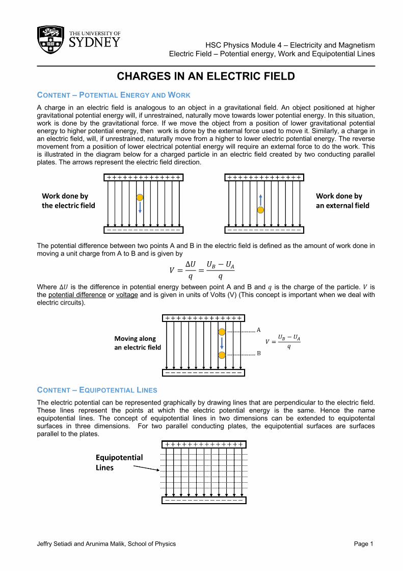
CHARGES IN AN ELECTRIC FIELD CONTENT – POTENTIAL ENERGY AND WORK A charge in an electric field is analogous to an object in a gravitational field. An object positioned at higher gravitational potential energy will, if unrestrained, naturally move towards lower potential energy. In this situation, work is done by the gravitational force. If we move the object from a position of lower gravitational potential energy to higher potential energy, then work is done by the external force used to move it. Similarly, a charge in an electric field, will, if unrestrained, naturally move from a higher to lower electric potential energy. The reverse movement from a posiition of lower electrical potential energy will require an external force to do the work. This is illustrated in the diagram below for a charged particle in an electric field created by two conducting parallel plates. The arrows represent the electric field direction.
The potential difference between two points A and B in the electric field is defined as the amount of work done in moving a unit charge from A to B and is given by
𝑉 =∆𝑈𝑞 =
𝑈& − 𝑈(𝑞
Where ∆𝑈 is the difference in potential energy between point A and B and 𝑞 is the charge of the particle. 𝑉 is the potential difference or voltage and is given in units of Volts (V) (This concept is important when we deal with electric circuits).
CONTENT – EQUIPOTENTIAL LINES The electric potential can be represented graphically by drawing lines that are perpendicular to the electric field. These lines represent the points at which the electric potential energy is the same. Hence the name equipotential lines. The concept of equipotential lines in two dimensions can be extended to equipotental surfaces in three dimensions. For two parallel conducting plates, the equipotential surfaces are surfaces parallel to the plates.

HSC Physics Module 4 – Electricity and Magnetism Electric Field – Potential energy, Work and Equipotential Lines
Jeffry Setiadi and Arunima Malik, School of Physics Page 2
Since the electric potential along an equipotential line is the same, no work is done moving a charged particle along the equipotential line. However, moving the particle from one equipotential line to another will require work either by the electric field or an external force.
Below are two more examples of equipotential lines for a single positive charge and for two positive charges. Red lines represent the electri field lines while the dashed lines represent the equipotential lines.
QUESTION 1 Calculate the amount of work done by an electric field (1.0 V/m) on a particle with a charge of 1.0 C that moves along an equipotential surface. QUESTION 2 - PENCIL Draw the equipotential lines for the positive and negative charges below.
HSC Physics Module 4 – Electricity and Magnetism Electric Circuits – Series and Parallel Circuits
Jeffry Setiadi and Arunima Malik, School of Physics Page 1
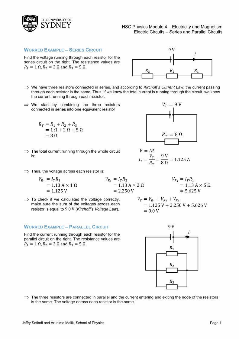
WORKED EXAMPLE – SERIES CIRCUIT Find the voltage running through each resistor for the series circuit on the right. The resistance values are 𝑅" = 1Ω, 𝑅( = 2Ωand𝑅- = 5Ω.
Þ We have three resistors connected in series, and according to Kirchoff’s Current Law, the current passing through each resistor is the same. Thus, if we know the total current is running through the circuit, we know the current running through each resistor.
Þ We start by combining the three resistors connected in series into one equivalent resistor
𝑅/ = 𝑅" + 𝑅( + 𝑅- = 1Ω + 2Ω + 5Ω = 8Ω
Þ The total current running through the whole circuit is:
𝑉 = 𝐼𝑅
𝐼/ =𝑉/𝑅/
=9V8Ω = 1.125A
Þ Thus, the voltage across each resistor is:
𝑉89 = 𝐼/𝑅" = 1.13A × 1Ω = 1.125V
𝑉8< = 𝐼/𝑅( = 1.13A × 2Ω = 2.250V
𝑉89 = 𝐼/𝑅" = 1.13A × 5Ω = 5.625V
Þ To check if we calculated the voltage correctly, make sure the sum of the voltages across each resistor is equal to 9.0V (Kirchoff’s Voltage Law).
𝑉/ = 𝑉89 + 𝑉8< + 𝑉8? = 1.125V + 2.250V + 5.626V = 9.0V
WORKED EXAMPLE – PARALLEL CIRCUIT Find the current running through each resistor for the parallel circuit on the right. The resistance values are 𝑅" = 1Ω, 𝑅( = 2Ωand𝑅- = 5Ω.
Þ The three resistors are connected in parallel and the current entering and exiting the node of the resistors
is the same. The voltage across each resistor is the same.
HSC Physics Module 4 – Electricity and Magnetism Electric Field – Series and Parallel Circuits
Jeffry Setiadi and Arunima Malik, School of Physics Page 2
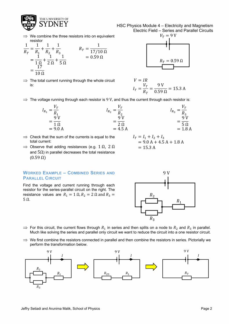
Þ We combine the three resistors into on equivalent resistor
1𝑅/
=1𝑅"+1𝑅(+1𝑅-
=11Ω +
12Ω +
15Ω
=1710Ω
𝑅/ =1
17/10Ω
= 0.59Ω
Þ The total current running through the whole circuit is:
𝑉 = 𝐼𝑅
𝐼/ =𝑉/𝑅/
=9V
0.59Ω = 15.3A
Þ The voltage running through each resistor is 9V, and thus the current through each resistor is:
𝐼89 =𝑉/𝑅"
=9V1Ω
= 9.0A
𝐼8< =𝑉/𝑅(
=9V2Ω
= 4.5A
𝐼8? =𝑉/𝑅-
=9V5Ω
= 1.8A Þ Check that the sum of the currents is equal to the
total current: Þ Observe that adding resistances (e.g. 1Ω, 2Ω
and 5Ω) in parallel decreases the total resistance (0.59Ω)
𝐼/ = 𝐼" + 𝐼( + 𝐼- = 9.0A + 4.5A + 1.8A = 15.3A
WORKED EXAMPLE – COMBINED SERIES AND PARALLEL CIRCUIT Find the voltage and current running through each resistor for the series-parallel circuit on the right. The resistance values are 𝑅" = 1Ω, 𝑅( = 2Ωand𝑅- =5Ω.
Þ For this circuit, the current flows through 𝑅" in series and then splits on a node to 𝑅( and 𝑅- in parallel.
Much like solving the series and parallel only circuit we want to reduce the circuit into a one resistor circuit.
Þ We first combine the resistors connected in parallel and then combine the resistors in series. Pictorially we perform the transformation below.

HSC Physics Module 4 – Electricity and Magnetism Electric Field – Series and Parallel Circuits
Jeffry Setiadi and Arunima Malik, School of Physics Page 3
Þ Below is the working out of combining the resistors as shown above 1𝑅(-
=1𝑅(
+1𝑅-
=12Ω +
15Ω
=7
10Ω
𝑅(- =17
10𝛺
= 1.43𝛺
𝑅/ = 𝑅(- + 𝑅" = 1.43Ω + 1Ω = 2.43Ω
Þ The total current is: 𝑉 = 𝐼𝑅
𝐼/ =𝑉/𝑅/
=9.0V2.43Ω = 3.70A
Þ Once we have the total current, we work our way back and expand the circuit to get the current and voltages
Þ The current is constant for resistors connected in series. Thus 3.70A flows through both 𝑅(- and 𝑅".
Þ The voltage across 𝑅(- and 𝑅" is:
𝑉8<? = 𝐼/𝑅(- = 3.70A × 1.43Ω = 5.30V
𝑉89 = 𝐼/𝑅"
= 3.70A × 1Ω = 3.70V
Þ Check sum of voltage is equal to 9.0V: 𝑉/ = 𝑉8<? + 𝑉89 = 5.30V + 3.70V = 9.0V
Þ Now that we have the voltage running through 𝑅(- we can calculate the current through 𝑅( and 𝑅-.
𝐼8< =𝑉8<?𝑅(
=5.29V2Ω
= 2.65A
𝐼8? =𝑉8<?𝑅-
=5.29V5Ω
= 1.05A
Þ Check that the sum of the currents is equal to 3.70A
𝐼8<? = 𝐼8< + 𝐼8? = 2.65A + 1.05A = 3.70A
Þ Summary of the current and voltages:
Voltage (V) Current (A) 𝑉" 3.70 𝐼" 3.70 𝑉( 5.30 𝐼( 2.65 𝑉- 5.30 𝐼- 1.05 𝑉T 9.00 𝐼T 3.70
HSC Physics Module 4 – Electricity and Magnetism Electric Circuits – Series and Parallel Circuits
Jeffry Setiadi and Arunima Malik, School of Physics Page 1
ELECTRIC CIRCUITS CONTENT – OHM’S LAW Ohm’s law relates the voltage (i.e. potential difference V) with the current and resistance of an ideal conductor. The law states that
𝑉 = 𝐼𝑅 where 𝐼 is the currrent and 𝑅 is the resistance of the conductor. The units for current and resistance is Ampere (A) and Ohm (Ω) respectively. The current is a measure of the flow of electrons in the circuit and is inversely proportional to the resistance. Hence, a large resistance will reduce the flow of electrons. As an analogy, this is similar to water flowing through a tube. A narrow tube will reduce the amount of water flowing through whilst larger tube will allow more water to flow through.
As a simple example, consider a one resistor circuit connected to a battery on the right. The battery provides a source of 9 V, and the resistance of the resistor is 2 Ω. With the information we have, we can calculate the current flowing through the resistor using Ohm’s law. The current flowing through the 2 Ω resistor is 𝐼 =𝑉/𝑅 = 9V/2Ω = 4.5A. If the resistance is doubled to 4Ω the current is reduced to 2.25 A.
It is important to note that resistors can either be ohmic or non-ohmic. Ohmic resistors have a constant resistance, hence in the equation above, if a resistor is an ohmic resistor with a constant resistance, then the graph of velocity against time is a straight line. In the case of non-ohmic resistors, where resistance in a resistor varies with, say current, then the graph of velocity against time is not a straight line. In the case of latter, the resistor is said not to obey Ohm’s Law. CONTENT – SERIES CIRCUITS For a single resistor circuit like the circuit above applying Ohm’s law is trivial. However, when more than one resistor is connected in either series or parallel, then Ohm’s law cannot be applied the same way. For resistors connected in series (i.e. connected next to each other) the current flowing through each resistor is the same, but the voltage is divided amongst the resistors. For the circuit below with an incoming voltage of 𝑉/, the voltage drop after passing through 𝑅0 is 𝑉/ − 𝑉0. Then the voltage drop after passing through 𝑅2 is 𝑉/ − 𝑉0 − 𝑉2 and similarly for 𝑅3. Thus, after passing through each resistor the potential of the current flow decreases. If all resistors in series have same resistance, then the voltage drop across each resistor is the same. However, in the case of resistors with different resistance, the resistor with a greater resistance will result in the greatest voltage drop.
We can also use the analogy of water flowing from a higher to lower potential energy. Each drop in potential energy represents the electric current flowing through a resistor. When the water flows horizontally, there is no change in potential energy (like an electric current flowing through the wire). The sum of each potential energy drop is equal to the total potential energy the water is at initially. In electric circuits, this is called the Kirchoff’s Voltage Law (KVL), which states that the total potential difference in a closed circuit is equal to zero (i.e. conservation of energy).
HSC Physics Module 4 – Electricity and Magnetism Electric Field – Series and Parallel Circuits
Jeffry Setiadi and Arunima Malik, School of Physics Page 2
𝑉456758 = 𝑉/ = 𝑉0 + 𝑉2 +⋯+ 𝑉; The total resistance of resistors connected in series can be calculated by summing up the resistance value of each resistor.
𝑅456758 = 𝑅/ = 𝑅0 + 𝑅2 +⋯+ 𝑅; The total resistance is also called the equivalent resistance, and we can reduce the multi-resistor circuit to one equivalent resistor.
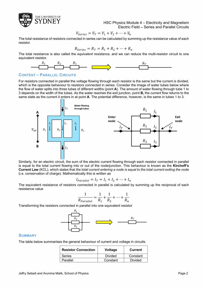
CONTENT – PARALLEL CIRCUITS For resistors connected in parallel the voltage flowing through each resistor is the same but the current is divided, which is the opposite behaviour to resistors connected in series. Consider the image of water tubes below where the flow of water splits into three tubes of different widths (point A). The amount of water flowing through tube 1 to 3 depends on the width of the tubes. As the water reaches the exit junction, point B, the current flow returns to the same state as the current it enters in at point A. The potential difference, however, is the same in tubes 1 to 3.
Similarly, for an electric circuit, the sum of the electric current flowing through each resistor connected in parallel is equal to the total current flowing into or out of the node/junction. This behaviour is known as the Kirchoff’s Current Law (KCL), which states that the total current entering a node is equal to the total current exiting the node (i.e. conservation of charge). Mathematically this is written as
𝐼<=6=>>5> = 𝐼/ = 𝐼0 + 𝐼2 + ⋯+ 𝐼; The equivalent resistance of resistors connected in parallel is calculated by summing up the reciprocal of each resistance value
1𝑅<=6=>>5>
=1𝑅0+1𝑅2+⋯+
1𝑅;
Transforming the resistors connected in parallel into one equivalent resistor
SUMMARY The table below summarises the general behaviour of current and voltage in circuits.
Resistor Connection Voltage Current Series Divided Constant Parallel Constant Divided
HSC Physics Module 4 – Electricity and Magnetism Electric Field – Series and Parallel Circuits
Jeffry Setiadi and Arunima Malik, School of Physics Page 3
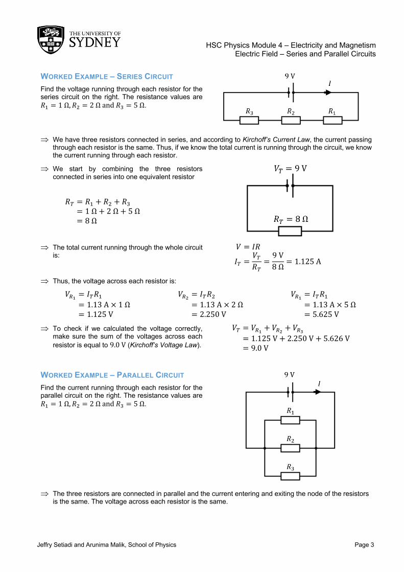
WORKED EXAMPLE – SERIES CIRCUIT Find the voltage running through each resistor for the series circuit on the right. The resistance values are 𝑅0 = 1Ω, 𝑅2 = 2Ωand𝑅3 = 5Ω.
Þ We have three resistors connected in series, and according to Kirchoff’s Current Law, the current passing through each resistor is the same. Thus, if we know the total current is running through the circuit, we know the current running through each resistor.
Þ We start by combining the three resistors connected in series into one equivalent resistor
𝑅/ = 𝑅0 + 𝑅2 + 𝑅3 = 1Ω + 2Ω + 5Ω = 8Ω
Þ The total current running through the whole circuit is:
𝑉 = 𝐼𝑅
𝐼/ =𝑉/𝑅/
=9V8Ω = 1.125A
Þ Thus, the voltage across each resistor is:
𝑉EF = 𝐼/𝑅0 = 1.13A × 1Ω = 1.125V
𝑉EI = 𝐼/𝑅2 = 1.13A × 2Ω = 2.250V
𝑉EF = 𝐼/𝑅0 = 1.13A × 5Ω = 5.625V
Þ To check if we calculated the voltage correctly, make sure the sum of the voltages across each resistor is equal to 9.0V (Kirchoff’s Voltage Law).
𝑉/ = 𝑉EF + 𝑉EI + 𝑉EL = 1.125V + 2.250V + 5.626V = 9.0V
WORKED EXAMPLE – PARALLEL CIRCUIT Find the current running through each resistor for the parallel circuit on the right. The resistance values are 𝑅0 = 1Ω, 𝑅2 = 2Ωand𝑅3 = 5Ω.
Þ The three resistors are connected in parallel and the current entering and exiting the node of the resistors
is the same. The voltage across each resistor is the same.

HSC Physics Module 4 – Electricity and Magnetism Electric Field – Series and Parallel Circuits
Jeffry Setiadi and Arunima Malik, School of Physics Page 4
Þ We combine the three resistors into on equivalent resistor
1𝑅/
=1𝑅0+1𝑅2+1𝑅3
=11Ω +
12Ω +
15Ω
=1710Ω
𝑅/ =1
17/10Ω
= 0.59Ω
Þ The total current running through the whole circuit is:
𝑉 = 𝐼𝑅
𝐼/ =𝑉/𝑅/
=9V
0.59Ω = 15.3A
Þ The voltage running through each resistor is 9V, and thus the current through each resistor is:
𝐼EF =𝑉/𝑅0
=9V1Ω
= 9.0A
𝐼EI =𝑉/𝑅2
=9V2Ω
= 4.5A
𝐼EL =𝑉/𝑅3
=9V5Ω
= 1.8A Þ Check that the sum of the currents is equal to the
total current: Þ Observe that adding resistances (e.g. 1Ω, 2Ω
and 5Ω) in parallel decreases the total resistance (0.59Ω)
𝐼/ = 𝐼0 + 𝐼2 + 𝐼3 = 9.0A + 4.5A + 1.8A = 15.3A
WORKED EXAMPLE – COMBINED SERIES AND PARALLEL CIRCUIT Find the voltage and current running through each resistor for the series-parallel circuit on the right. The resistance values are 𝑅0 = 1Ω, 𝑅2 = 2Ωand𝑅3 =5Ω.
Þ For this circuit, the current flows through 𝑅0 in series and then splits on a node to 𝑅2 and 𝑅3 in parallel.
Much like solving the series and parallel only circuit we want to reduce the circuit into a one resistor circuit.
Þ We first combine the resistors connected in parallel and then combine the resistors in series. Pictorially we perform the transformation below.

HSC Physics Module 4 – Electricity and Magnetism Electric Field – Series and Parallel Circuits
Jeffry Setiadi and Arunima Malik, School of Physics Page 5
Þ Below is the working out of combining the resistors as shown above 1𝑅23
=1𝑅2
+1𝑅3
=12Ω +
15Ω
=7
10Ω
𝑅23 =17
10𝛺
= 1.43𝛺
𝑅/ = 𝑅23 + 𝑅0 = 1.43Ω + 1Ω = 2.43Ω
Þ The total current is: 𝑉 = 𝐼𝑅
𝐼/ =𝑉/𝑅/
=9.0V2.43Ω = 3.70A
Þ Once we have the total current, we work our way back and expand the circuit to get the current and voltages
Þ The current is constant for resistors connected in series. Thus 3.70A flows through both 𝑅23 and 𝑅0.
Þ The voltage across 𝑅23 and 𝑅0 is:
𝑉EIL = 𝐼/𝑅23 = 3.70A × 1.43Ω = 5.30V
𝑉EF = 𝐼/𝑅0
= 3.70A × 1Ω = 3.70V
Þ Check sum of voltage is equal to 9.0V: 𝑉/ = 𝑉EIL + 𝑉EF = 5.30V + 3.70V = 9.0V
Þ Now that we have the voltage running through 𝑅23 we can calculate the current through 𝑅2 and 𝑅3.
𝐼EI =𝑉EIL𝑅2
=5.29V2Ω
= 2.65A
𝐼EL =𝑉EIL𝑅3
=5.29V5Ω
= 1.05A
Þ Check that the sum of the currents is equal to 3.70A
𝐼EIL = 𝐼EI + 𝐼EL = 2.65A + 1.05A = 3.70A
Þ Summary of the current and voltages:
Voltage (V) Current (A) 𝑉0 3.70 𝐼0 3.70 𝑉2 5.30 𝐼2 2.65 𝑉3 5.30 𝐼3 1.05 𝑉T 9.00 𝐼T 3.70

HSC Physics Module 4 – Electricity and Magnetism Electric Circuits – Heating Effects
Jeffry Setiadi and Arunima Malik, School of Physics Page 1
HEATING EFFECTS OF ELECTRIC CURRENTS CONTENT – CONSERVATION OF ENERGY An electric current that passes through an electric component will have its potential energy dropped by a certain amount (potential difference or voltage). Following the circuit on the right, the electric current flows from a source starting from the positive terminal. As the current passes through the resistor, the potential energy of the electric current drops between point A and B. Finally, the current flows to the negative terminal completing the circuit. Following the law of conservation of energy, the drop in potential energy from point A to B must be transformed into a different kind of energy (the energy loss across the resistor cannot be destroyed). For a resistor, the electrical energy is transferred into heat (electrical to thermal). Other devices connected similarly will convert the electrical energy differently. Examples include electric current passing through a motor connected to a mechanical load, light bulb and a storage battery. The electrical energy is transferred as work done on the mechanical load (electrical to mechanical), converted to light (electrical to electromagnetic) and transferred to a stored chemical in the battery (electrical to chemical).
CONTENT – POWER IN CIRCUITS The transfer of energy is quantitatively described with a variable called power, 𝑃. The units for 𝑃 is joule/sec or Watts, hence it is a measure of the amount of energy transferred per second or unit time. The power transferred from electric current is given by the voltage multiplied by the current. 𝑃 = 𝑉𝐼 (1)
To check if the expression above is correct, we will look at the units of both voltage and current. Voltage is defined as the amount of work done per unit charge (joule/coulomb), and current is the flow of charge per unit time (coulomb/sec). Thus, if we have 1 Volt and 1 Amp the multiplication of the two is
HSC Physics Module 4 – Electricity and Magnetism Electric Field – Heating Effects
Jeffry Setiadi and Arunima Malik, School of Physics Page 2
1Joule
Coulomb× 1
Coulombsec
= 1Joulesec
or1Watt
which is the unit for power. We can combine Ohm’s law with the power equation above to get the dissipation rate of electrical energy across a resistor. Ohm’s law is usually written as 𝑉 = 𝐼𝑅 and if we substitute Ohm’s law into equation (1) we get 𝑃 = (𝐼𝑅) × 𝐼 = 𝐼9𝑅 (2)
If instead, we write Ohm’s law as 𝐼 = 𝑉/𝑅 then power dissipated across the resistor is
𝑃 = 𝑉 × ;𝑉𝑅< =
𝑉9
𝑅 (3)
In the case of a series circuit, where current is the same across all resistors, the resistor with the greater resistance will have a greater power dissipation. In other words, if current 𝐼 stays the same in equation 2), then the greater the resistance, the greater the power dissipation. In the case of a parallel circuit, however, where voltage across the resistors stays the same, the resistor with the greater resistance will have a smaller power dissipation. This can be explained by visualising voltage 𝑉 as a constant in equation 3) and varying the resistance 𝑅.
It is important to remember that equation (1) is the rate of transfer of electrical energy to all forms of energy. Equation (2) and (3) gives the rate of transfer of electrical energy to thermal energy for an electrical component with resistance. This behaviour of electric current in circuits is used in the design of electric heaters.
QUESTION 1 A 30 Ω resistor is connected to a 9.0 V battery as shown on the circuit on the right.
a) How much work is done on moving an electron across the resistor? b) What is the rate of energy transferred into heat across the resistor? c) How much thermal energy is produced in 1 hour?
ans: (a) 9.0 J (b) 2.7 W (c) 9.7 kJ QUESTION 2 Heat is generated in a resistor at a rate of 50 W. If the current running through the resistor is 1.5 A what is the resistance value of the resistor? What is potential difference across the resistor?
ans: R=22.2 Ω and V=33.3 V QUESTION 3 The standard voltage in Australia is 230 V and if a 1000 W heater is plugged into an outlet, find:
a) The amount of current flowing through the heater b) The resistance of the heater c) The total cost of continuously running the bulb for seven days if it cost 12.5 cents/(kW.h)
ans: (a) 4.3 A (b) 53.5 Ω (c) $21.00
QUESTION 4 INTERNET RESEARCH
a) Investigate the physics of fireworks in terms of energy conversions. How many energy conversions can you list?
b) Research the power consumption of common household appliances. Pick one appliance and study the energy rating of that appliance. What does the star rating mean?
HSC Physics Module 4 – Electricity and Magnetism
Kathryn Ross, School of Physics, 2017 Page 1
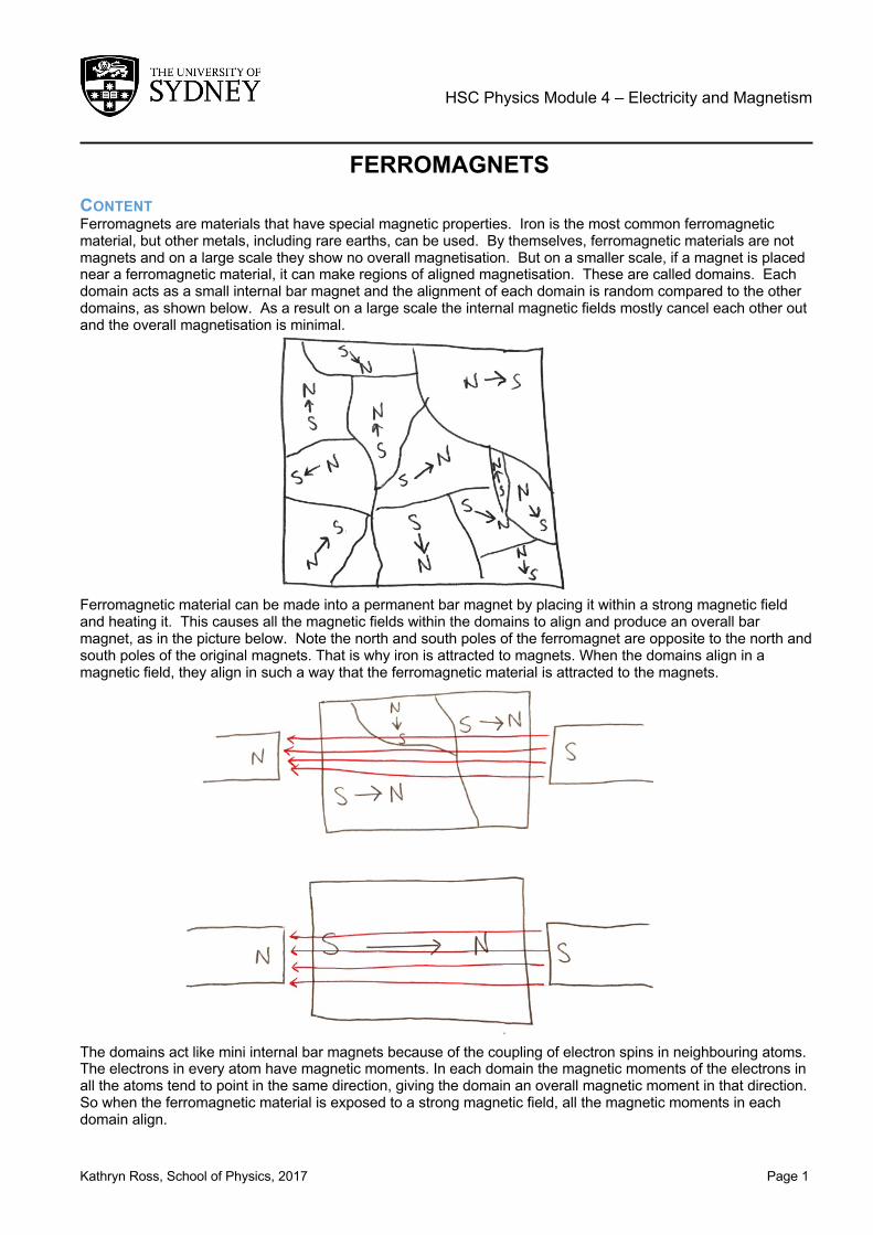
FERROMAGNETS CONTENT Ferromagnets are materials that have special magnetic properties. Iron is the most common ferromagnetic material, but other metals, including rare earths, can be used. By themselves, ferromagnetic materials are not magnets and on a large scale they show no overall magnetisation. But on a smaller scale, if a magnet is placed near a ferromagnetic material, it can make regions of aligned magnetisation. These are called domains. Each domain acts as a small internal bar magnet and the alignment of each domain is random compared to the other domains, as shown below. As a result on a large scale the internal magnetic fields mostly cancel each other out and the overall magnetisation is minimal.
Ferromagnetic material can be made into a permanent bar magnet by placing it within a strong magnetic field and heating it. This causes all the magnetic fields within the domains to align and produce an overall bar magnet, as in the picture below. Note the north and south poles of the ferromagnet are opposite to the north and south poles of the original magnets. That is why iron is attracted to magnets. When the domains align in a magnetic field, they align in such a way that the ferromagnetic material is attracted to the magnets.
The domains act like mini internal bar magnets because of the coupling of electron spins in neighbouring atoms. The electrons in every atom have magnetic moments. In each domain the magnetic moments of the electrons in all the atoms tend to point in the same direction, giving the domain an overall magnetic moment in that direction. So when the ferromagnetic material is exposed to a strong magnetic field, all the magnetic moments in each domain align.

HSC Physics Module 4 – Electricity and Magnetism
Kathryn Ross, School of Physics Page 2
EXAMPLE Using your understanding of ferromagnetic material, explain how iron filings (small particles of iron) can be used to display magnetic fields.
Þ So, firstly, we know that iron is a ferromagnetic material so it’s very responsive to magnets. They also have domains which have aligned magnetisation. When a magnet is placed inside or near the iron filings, the domains within the iron filings become aligned. Due to the shape of the iron filings, their lowest energy configuration has the magnetisation aligned along the longest side of each individual iron filing. Like all ferromagnets in the presence of a strong magnetic field, the ferromagnets align in the opposite direction of the magnetic field. This means they wish to stay within the magnetic field. The iron filings are also small enough that the friction of the surface is usually too small to stop the iron filings from moving. So each individual iron filing will move so that its longest side is aligned in the direction of the magnetic field. Thus, the iron filings move to point along the direction of the magnetic field, allowing us to see what the magnetic field lines look like. In the diagram below, the red lines are the magnetic field lines and the small black lines represent the iron filings.
HSC Physics Module 4 – Electricity and Magnetism
Kathryn Ross, School of Physics, 2017 Page 1
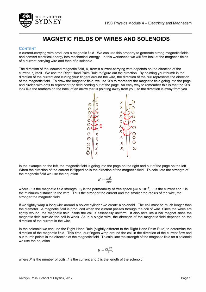
MAGNETIC FIELDS OF WIRES AND SOLENOIDS CONTENT A current-carrying wire produces a magnetic field. We can use this property to generate strong magnetic fields and convert electrical energy into mechanical energy. In this worksheet, we will first look at the magnetic fields of a current-carrying wire and then of a solenoid. The direction of the induced magnetic field, 𝐵, from a current-carrying wire depends on the direction of the current, 𝐼, itself. We use the Right Hand Palm Rule to figure out the direction. By pointing your thumb in the direction of the current and curling your fingers around the wire, the direction of the curl represents the direction of the magnetic field. To draw the magnetic field, we use ‘X’s to represent the magnetic field going into the page and circles with dots to represent the field coming out of the page. An easy way to remember this is that the ‘X’s look like the feathers on the back of an arrow that is pointing away from you, so the direction is away from you.
In the example on the left, the magnetic field is going into the page on the right and out of the page on the left. When the direction of the current is flipped so is the direction of the magnetic field. To calculate the strength of the magnetic field we use the equation
𝐵 = $%&'()
, where 𝐵 is the magnetic field strength, 𝜇+ is the permeability of free space (4𝜋 × 1012), 𝐼 is the current and 𝑟 is the minimum distance to the wire. Thus the stronger the current and the smaller the radius of the wire, the stronger the magnetic field. If we tightly wrap a long wire around a hollow cylinder we create a solenoid. The coil must be much longer than the diameter. A magnetic field is produced when the current passes through the coil of wire. Since the wires are tightly wound, the magnetic field inside the coil is essentially uniform. It also acts like a bar magnet since the magnetic field outside the coil is weak. As in a single wire, the direction of the magnetic field depends on the direction of the current in the wire. In the solenoid we can use the Right Hand Rule (slightly different to the Right Hand Palm Rule) to determine the direction of the magnetic field. This time, our fingers wrap around the coil in the direction of the current flow and our thumb points in the direction of the magnetic field. To calculate the strength of the magnetic field for a solenoid we use the equation
𝐵 = $%4&5
, where 𝑁 is the number of coils, 𝐼is the current and 𝐿 is the length of the solenoid.
HSC Physics Module 4 – Electricity and Magnetism
Kathryn Ross, School of Physics Page 2
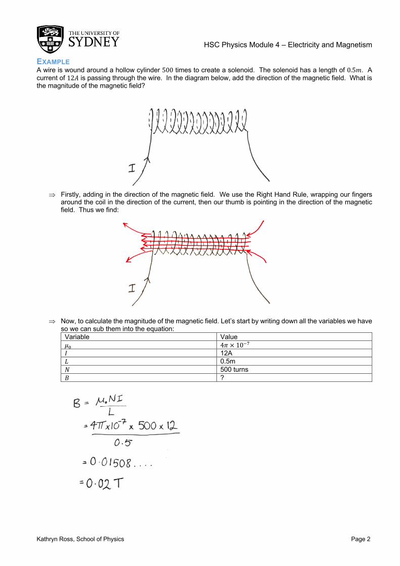
EXAMPLE A wire is wound around a hollow cylinder 500 times to create a solenoid. The solenoid has a length of 0.5𝑚. A current of 12𝐴 is passing through the wire. In the diagram below, add the direction of the magnetic field. What is the magnitude of the magnetic field?
Þ Firstly, adding in the direction of the magnetic field. We use the Right Hand Rule, wrapping our fingers around the coil in the direction of the current, then our thumb is pointing in the direction of the magnetic field. Thus we find:
Þ Now, to calculate the magnitude of the magnetic field. Let’s start by writing down all the variables we have so we can sub them into the equation:
Variable Value 𝜇+ 4𝜋 × 1012 𝐼 12A 𝐿 0.5m 𝑁 500 turns 𝐵 ?