charge lifetime, emittance, and surface analysis studies
TRANSCRIPT

Operated by the Southeastern Universities Research Association for the U.S. Department of Energy
Thomas Jefferson National Accelerator Facility Page 1 Thomas Jefferson National Accelerator Facility Operated by the Southeastern Universities Research Association for the U.S. Department of Energy
Charge Lifetime, Emittance, and Surface Analysis Studies
of K2CsSb Photocathode in a JLab DC High Voltage Gun
J. L. McCarter1, T. Rao2, J. Smedley2, R. Mammei3, M. Poelker3, R. Suleiman3
1University of Virginia, 2Brookhaven National Laboratory, 3Thomas Jefferson National Accelerator Facility
20 October 2011 ERL 11, KEK, Tsukuba, Japan

Operated by the Southeastern Universities Research Association for the U.S. Department of Energy
Thomas Jefferson National Accelerator Facility Page 2
Story starts with PAC11 results
• Lifetime data taken at 100kV, 1mA, 532nm
• Similar performance to GaAs, not exactly what was hoped for…
• However, exact stoichiometry of cathode unknown, as K dispenser depleted during deposition.

Operated by the Southeastern Universities Research Association for the U.S. Department of Energy
Thomas Jefferson National Accelerator Facility Page 3
Initial 440 nm, 850 µm spot size results
• No QE decay was observed for all 1 mA runs at up to 100 C extracted at 100 and 200 kV bias voltages and every spot tested on the cathode, even from the EC.
• QE actually increases during the 3 mA run despite several short pressure increases (vacuum events) in the beamline and gun chamber that temporarily reduced the QE.
— Short pressure/vacuum events are due to full active area and poor spatial quality of blue laser beam (halo).

Operated by the Southeastern Universities Research Association for the U.S. Department of Energy
Thomas Jefferson National Accelerator Facility Page 4
And then problems…(but not really)
Beam hit end of Bellows Mu Metal case over bellows
QE scan after event with 440 nm (850 micron spot) Run location
A power glitch caused some beam steering magnets to reset causing the electron beam to scrape a portion of the beam pipe. The high voltage and laser were not affected which resulted in 3 mA beam being extracted from the cathode in 5x10⁻¹⁰ Torr environment for ~2hours
Went back to running at 5 mA at a new spot, and the QE just kept going up…..
Is it laser heating or some kind of photochemistry?
Vacuum rise from beam into bellows around 100x increase in vacuum level
Operated by the Southeastern Universities Research Association for the U.S. Department of Energy
Thomas Jefferson National Accelerator Facility Page 5
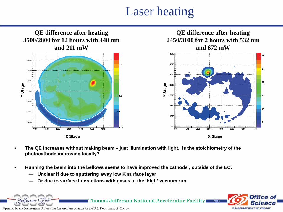
Laser heating
• The QE increases without making beam – just illumination with light. Is the stoichiometry of the photocathode improving locally?
• Running the beam into the bellows seems to have improved the cathode , outside of the EC. — Unclear if due to sputtering away low K surface layer — Or due to surface interactions with gases in the ‘high’ vacuum run
QE difference after heating 2450/3100 for 2 hours with 532 nm
and 672 mW
QE difference after heating 3500/2800 for 12 hours with 440 nm
and 211 mW

Operated by the Southeastern Universities Research Association for the U.S. Department of Energy
Thomas Jefferson National Accelerator Facility Page 6
532 nm, redo, at 200 kV, 350 µm spot
• Entire surface (other than QE hole at center) has higher QE than before running 440 nm and the vacuum event.
• QE near run locations dramatically higher than before
3.0 mA Run Before 0.7% After 1.3%
5.0 mA run (also heated at this location) Before 0.5% After 1.4%
% Location of no beam, ever
Before 0.5% After 0.8%

Operated by the Southeastern Universities Research Association for the U.S. Department of Energy
Thomas Jefferson National Accelerator Facility Page 7
More 532 nm lifetimes
• Decided to run maximum beam possible at 100 kV • Limited by laser power and possible beam dump heating
Things were “normal” at 10 mA
Then we see a slight QE decline at 16 mA
Sharp QE decline at 20 mA
QE Change before and after the run.
Center of run location lost QE, surroundings gained.
Earlier, we saw laser heating seemed to help, but now it seems it only helps up to certain laser levels.

Operated by the Southeastern Universities Research Association for the U.S. Department of Energy
Thomas Jefferson National Accelerator Facility Page 8
More laser heating?
After heating 2250x/1500y with ~4 W for 30 mins.
After heating 3200x/1500y with ~4 W for 1.5 hr.
If it is really laser heating, then let’s decrease the power density by increasing the spot size and first
watch for QE decline from illuminating a spot before running beam with 800 µm spot, 200 kV.
And then run…
Needed laser power near 4.5W to get beam current up to 20 mA.
Beam shape was very large and the radiation/vacuum along the beam pipe
was larger than expected.

Operated by the Southeastern Universities Research Association for the U.S. Department of Energy
Thomas Jefferson National Accelerator Facility Page 9
Spot size side by side
At 100 kV, the spot size increased roughly by a factor of 5, yet the lifetime went up by a factor of 20 or more, indicating that the decreased laser power density on the cathode increased lifetime.
Even at longer runs, the QE decay now (after
the major vacuum event) is much slower than GaAs
10 mA, 200 kV, 532 nm, 350 μm spot

Operated by the Southeastern Universities Research Association for the U.S. Department of Energy
Thomas Jefferson National Accelerator Facility Page 10
Emittance work
Done via solenoid scan technique at 100 and 200 kV, and 3 µA of beam.
Summary of Emittance Measurements
Laser Wavelength (nm)
Laser FWHM (um) HV (kV)
Normalized Emittance (mm mrad/mm(rms)
440 850 100 1.11 +/- 0.10 440 850 200 0.97 +/- 0.18 532 330 100 1.25 +/- 0.08 532 330 200 1.12 +/- 0.35 532 700 100 1.01 +/- 0.08 532 700 200 1.19 +/- 0.27
• Emittance was roughly twice that of previous measurements made at Cornell on a similar cathode .
• The increase can partially be attributed to the high surface roughness of the JLab/BNL photocathode (coming up).

Operated by the Southeastern Universities Research Association for the U.S. Department of Energy
Thomas Jefferson National Accelerator Facility Page 11
How to kill a cathode….
Before Heating NEGS After Heating NEGS: 5.0A (4 hr), 9.3 A (3hr), 8.0 A (0.5 hr)
8E-10 Torr (mostly H2)
After more Heating NEGS: 5.0A (4 hr), 9.3 A (3 hr), 8.0 A (17 hr), 0.0A (6 hr)
Ion pump =0.4 nA, Ext. Gauge off
Heated the NEGs in the hopes of running beam in a high H2 environment.
Photograph of puck right after pulling into the prep
chamber
Very bad lifetime, but unknown if due to vacuum or heat. The entire gun chamber became warm to the touch, including the HV cable, indicating that the photocathode heated, though to an unknown amount. Also, QE of entire cathode dropped by 1/3.

Operated by the Southeastern Universities Research Association for the U.S. Department of Energy
Thomas Jefferson National Accelerator Facility Page 12
Try (but fail) to recover with Cs.. •Moved puck into prep chamber (used for activation of GaAs) to add Cs. •Heated puck up to 120 C - photocurrent 9-10 pA during ramp up. •130 C – photocurrent drop to 5 pA. Time Cs Strip
Current (A/C ) A Puck Temp
°C Ion Pump
Current (nA) White light
Photocurrent (pA)
15:39 4.5 133 500 4
15:44 4.5 133 600 3
15:54 4.5 134 700 2.1
15:57 4.6 134 780 1.5
16:03 4.6 134 830 1.5
16:13 4.6 134 960 1.5
16:25 4.6 134 1000 .7
Started Adding Cesium Immediately the photocurrent went up and then fell. After this and for the rest of the Cesiation, no observable photocurrent at 532nm. Saw a modest change in photocurrent with white light. Heated Cesium strip for ~1 hr.
Turned off Cs, moved out of the way, measured photocurrent, and moved puck off the heater to a puck transfer manipulator to
cool.
Photocurrent before
heating (pA)
Photocurrent after cesium hot
puck (pA)
White light
n/a 28
410 nm 130 7
530 nm 13 0

Operated by the Southeastern Universities Research Association for the U.S. Department of Energy
Thomas Jefferson National Accelerator Facility Page 13
SEM the dead photocathode
Taken after all measurements in the DC gun. Transferred to SEM via argon bag.
Spot 1 Spot 2
Spot 3 Spot 4
Images of the spots at 400x with 20 keV
electrons.
2 1 3 4
Operated by the Southeastern Universities Research Association for the U.S. Department of Energy
Thomas Jefferson National Accelerator Facility Page 14
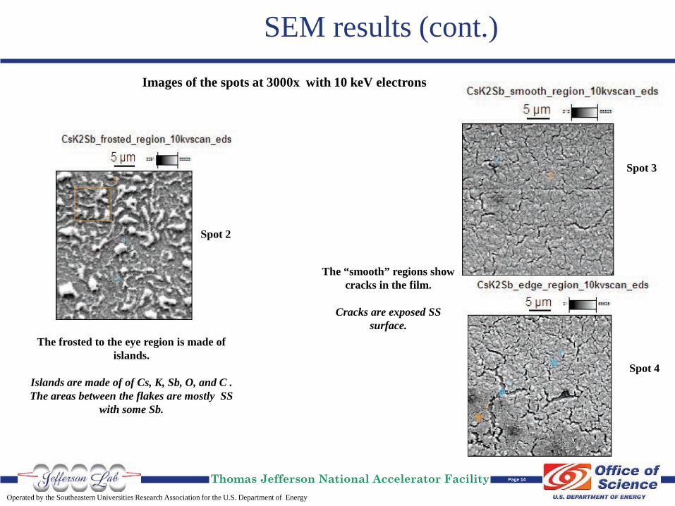
SEM results (cont.)
Images of the spots at 3000x with 10 keV electrons
Spot 2
Spot 3
Spot 4
The frosted to the eye region is made of islands.
Islands are made of of Cs, K, Sb, O, and C . The areas between the flakes are mostly SS
with some Sb.
The “smooth” regions show cracks in the film.
Cracks are exposed SS
surface.

Operated by the Southeastern Universities Research Association for the U.S. Department of Energy
Thomas Jefferson National Accelerator Facility Page 15
Summary and Future Work
Summary
•Initially promising results at 440 nm •Vacuum event modified surface to drastically improve 532 nm performance •Local heating can either increase/decrease lifetime •Emittance higher than other measurements •Global heating very, very bad for cathode •Recovery of QE by addition of Cs unsuccessful •SEM shows very rough surface
Future
•Obtain new cathode with proper stoichiometry •Measure emittance as soon as put in Jlab gun •Lifetime in bad vacuum, without heating puck •Lifetime at higher current (up to 30 mA supply)
Take away message….
Unlike GaAs, K2CsSb can take a beating and keep on ticking….

Operated by the Southeastern Universities Research Association for the U.S. Department of Energy
Thomas Jefferson National Accelerator Facility Page 16
The End
• Any questions? • Comments?