charge detection methods for dielectrics –...
TRANSCRIPT

Trek Application Note Number 3005
Charge Detection Methods for Dielectrics – Overview
Dr. Maciej A. Noras
Abstract This paper is intended to provide a brief overview of charge detection methods usedin research and in many industrial applications. Attention was brought especially to "macroscopic"methods that are suitable for large quantity and volume investigations of various materials and struc-tures.
1 Introduction
The importance of charge phenomena occurringin dielectrics has been recognized for a long timeby many scientists and engineers. Over the years,as electrical and electronic equipment have be-come smaller and more compact, the insulat-ing materials used are experiencing increasinglyhigher electrical stresses. It has been found thatunder such enhanced electric field conditions thecharging and charge trapping phenomena arevery important factors to be considered when de-signing insulation systems. A great number ofmethods and techniques has been developed toinvestigate space and surface charge distributionsin various materials. Trek, Inc. has been rec-ognized for its expertise in non-contact and non-invasive probe methods of surface charge mea-surements. A broad line of electrostatic volt-meters (ESVM) had been developed in order toaccommodate various needs and requirements ofscientific and industrial applications. However, it isimportant to realize that there are also other tech-niques for measurements of surface and volumecharges in various materials. The intention of thisoverview is to briefly describe the most popularcharge measurement technologies available, and,in this way, provide a base for informed choice ofthe most appropriate technique. All microscopicmethods were omitted as they are considered notsuitable for high volume tests.
2 Thermal Methods
Thermal techniques are most easily applied tothin films. If used for relatively thick samples, theelectric field intensity is allowed to vary only in
the direction normal to the plane of the sample,otherwise the measurement becomes inaccurate.Usually samples tested with thermal methods re-quire poling under DC high voltage with electricfield intensities ranging up to 50 [kV/mm] [1]. Ei-ther corona or contact poling with high voltages upto 30 [kV] can be conducted with Trek’s 30/20 or20/20C High Voltage Power Amplifiers. For lowervoltage requirements other Trek amplifiers can beused.
2.1 Thermal Pulse Methods (TPM).
The idea of this measurement is application of thethermal pulse to one of the surfaces of the inves-tigated dielectric material (Figure 1). The electri-cal response generated in the sample carries theinformation about the charge or polarization dis-tribution. Unfortunately, it is a convoluted func-tion of space and time and requires use of appro-priate mathematical methods to correctly interpretthe results. Also, the time of measurement is rela-tively long. As a source of thermal pulse, the lightflash is frequently used [1–5]. For the purpose ofcharge or current measurement, Trek’s Model 217Coulombmeter/Ammeter can be employed. Ad-vantages of the method are:
• good resolution (2 [µm]),
• applies to relatively thick samples,
• possible non-contact measurements.
Disadvantages of the TPM technique:
• resulting electrical signal is a convolutedfunction of space and time and requires ad-vanced mathematical solution methods.
TREK, INC. • 190 Walnut Street • Lockport, NY 14094 • Tel: (716) 438-7555
Call: 1 800 FOR TREK • FAX: (716) 201-1804 • E-mail: [email protected] • Web: www.trekinc.com
page 1 of 13Copyright © 2013 TREK, INC. 1303/MAN Rev. 0e

Trek Application Note Number 3005
Charge Detection Methods for Dielectrics – Overview
Figure 1: Thermal pulse method measurementsetup
2.2 Laser Intensity ModulationMethod (LIMM).
This method uses modulated surface heatingof the dielectric samples. It produces spatiallynonuniform temperature distribution through thethickness of the specimen. The sine-modulatedlaser beam is often used as a source of the heatwave. Such heat signal causes a sinusoidal fluc-tuation in temperature of the front electrode andthermal wave penetration into the sample (Figure2). The waves are attenuated as they progressthrough the material. An interaction of aforemen-tioned thermal field with space charges present inthe sample produces a sinusoidal pyroelectric cur-rent [6]. With the thermal wave method it is possi-ble to create a strong temperature oscillation nearthe surface, but no localized strong oscillation atan arbitrary depth in the sample (this follows fromthe heat conduction equation). In mathematicalterms, the measured current is a convolution ofthe pyroelectric coefficient p(x) with the tempera-ture distribution:
I∼
(ω) ∝ k∫ d
0p(x)
cosh[k(d-x)]sinh(kd)
dx (1)
where
k(ω) =(
ω
2D
)1/ 2(2)
Iv
is a pyroelectric current, D is a thermal diffu-sivity and d is a thickness of the sample. Unfortu-nately, solving for p(x) is an ill–conditioned prob-lem and appropriate numerical methods have tobe used.
I-Uconverter
Lock-inamplifier
Functiongenerator
Laserdiode
electrodes
substrate
sample
Trek Model 217
Figure 2: Laser Intensity Modulation Methodsetup
3 Pressure Pulse Methods(PPM)
There exists quite a number of techniques thatcan be classified as pressure pulse methods [7–9]. They depend on phenomena occurring whenan ultrasonic pulse propagates through the sam-ple (Figure 3). Assuming that the considered ma-terial is homogeneous and non–conducting, thecurrent I(t) flowing due to the material’s reactionto the external pressure pulse can be describedas:
I(t) = X · C0G(εr )∫ zf
0E(z, 0)
∂
∂tp(z, t)dz (3)
TREK, INC. • 190 Walnut Street • Lockport, NY 14094 • Tel: (716) 438-7555
Call: 1 800 FOR TREK • FAX: (716) 201-1804 • E-mail: [email protected] • Web: www.trekinc.com
page 2 of 13Copyright © 2013 TREK, INC. 1303/MAN Rev. 0e

Trek Application Note Number 3005
Charge Detection Methods for Dielectrics – Overview
where X is the compressibility of the material,G(εr ) is a function of the relative permittivity (di-electric constant) εr , which in turn depends onthe pressure distribution in the sample. E(z,0) isthe electric field distribution at the time t=0, p(z,t)is the pressure distribution and C0 is the capaci-tance of the non–compressed sample:
C0 = ε0εr · S/d (4)
Where d is the thickness of the sample, S is thesample area.At the same time, the voltage difference V(t)across the sample is described by:
V (t) = X · G(εr )∫ zf
0E(z, 0)p(z, t)dz (5)
The information about charge distribution can beextracted using Poisson’s equation:
∇2V =
ρ
ε0εr(6)
p(z,
t)
d istance z
pressurewave
z f d
v
ε'r(p) εr
electrodes
Figure 3: Principle of the Pressure Pulse Methods
Techniques that belong to this family share thesame measurement principle, the difference is inthe method of initiating the pressure pulse thattravels through the measured sample.
3.1 Laser Induced Pressure PulseMethod (LIPP).
The resolution of this method and of all pressurepulse methods depends strictly on the width of thepressure disturbance wave. The pressure waveis generated by absorbing a laser light pulse ina metal target bonded to the dielectric sample.For a very short pulse (around 1 [ns]), the elec-trical response gives the spatial distribution of theelectric field and charge density. This method isused also for surface charge distribution measure-ments [7,8,10,11].
3.2 Thermoelastically GeneratedLIPP.
The pressure wave excitation comes from a laserlight pulse striking an optically absorbing layer lo-cated on one of electrodes. Resolution of thistechnique is around 1[µm] [12].
3.3 Piezoelectrically Induced Pres-sure Pulse (PIPP).
This method is very similar to LIPP method. Thepressure wave is generated by a piezoelectrictransducer [9,13].
3.4 Non-Structured Acoustic PulseMethod (NSAPM).
A typical measurement system consists of anacoustic pulse generator, receiver, and a data ac-quisition system. As a generator of the acousticsignal a high voltage spark is frequently used. Forsimple dielectric materials a resolution of 1 [mm]has been achieved [14].
TREK, INC. • 190 Walnut Street • Lockport, NY 14094 • Tel: (716) 438-7555
Call: 1 800 FOR TREK • FAX: (716) 201-1804 • E-mail: [email protected] • Web: www.trekinc.com
page 3 of 13Copyright © 2013 TREK, INC. 1303/MAN Rev. 0e

Trek Application Note Number 3005
Charge Detection Methods for Dielectrics – Overview
3.5 Laser-Generated Acoustic PulseMethod.
In order to improve repeatability and bandwidthof the NSAPM technique, the laser, as a powersource, was introduced. This led to the construc-tion of the system shown in Figure 4. The acous-tic pulses are created by the laser beam fired on athin paper target. A 50 [µm] resolution in 3 [mm]thick sample was recorded by using this method[15].
3.6 Acoustic Probe Method.
This method is based on the effect of generationof an electric signal by mechanical excitation ofthe charged sample. Resolutions of 0.2 [mm] canbe achieved using this technique [16].
Figure 4: Laser–Generated Acoustic PulseMethod [15]
The major disadvantage of the pressure wavemethods is poor reproducibility due to insufficientinformation about the pressure wave propagation.
4 Electro-Acoustic StressPulse Method
The principle of this technique is based upon theCoulomb force law. Externally applied pulsedelectric field induces a force perturbation in thepresence of resident charges. This creates anacoustic (or pressure) wave in the sample. Theacoustic signal can be detected using a piezo-electric transducer. The resolution of this methoddepends on the duration of the electric pulse andon the thickness of the sample. The densityand polarity of the space charge is obtained fromthe physical characteristics of the acoustic signal.The difficulty lies in the ability to apply the electricstress uniformly. Problems also arise when thecharge distribution and polarization profiles arecomplex. This method is also known as a pulsedelectro-acoustic (PEA) technique [17–19].
5 Thermal Step Method
By creating a temperature gradient across thesample the electric current is induced due tothermal expansion of the material.This methodis time consuming, although it is non–destructive[20–23].
6 Photoconductivity Method
This technique uses the light absorption phenom-ena in a thin photoconductive layer [24, 25]. Bythe detection of the photocurrent produced, theinformation about the charge distribution can beobtained. This method is relatively accurate andit is nondestructive providing a short illuminationtime with low light intensity.
TREK, INC. • 190 Walnut Street • Lockport, NY 14094 • Tel: (716) 438-7555
Call: 1 800 FOR TREK • FAX: (716) 201-1804 • E-mail: [email protected] • Web: www.trekinc.com
page 4 of 13Copyright © 2013 TREK, INC. 1303/MAN Rev. 0e

Trek Application Note Number 3005
Charge Detection Methods for Dielectrics – Overview
7 Field Probe Methods
This group of techniques is based on the capac-itive coupling principle [26, 27]. These methodsare used for surface charge and surface poten-tial measurements. The following subsections de-scribe leading methods which belong to the elec-trostatic field probe category.
7.1 Static charge detector.
The charge induced on a sensing electrode ismeasured with an electrometer. This method isvery sensitive to fluctuations of the distance be-tween sensing element and examined surface.Reported spatial resolution of 10 [µm] [28].
7.2 Dynamic current sensing.
A current sensing probe is placed close to the in-vestigated surface. As it moves in the directionparallel to the surface, a current is induced. Thiscurrent is proportional to the capacitive couplingand to the rate of change of the voltage betweenthe sensing element and the surface. This methodis very sensitive to changes in the surface-probedistance [26].
7.3 Surface potential probe.
The probe uses a mechanically vibrating sensorfor non-contact surface charge and/or voltage de-tection.The principle of operation is based on thecapacitive coupling between the surface undertest and the probe sensor (Figure 5). Voltage U1corresponds to a difference of potentials betweenthe probe and the ground (earth) reference andU2 is the voltage between the charged plane andground. The voltage U between the sensor andthe plate is then equal to |U1-U2|. Assuming thatthe probe is grounded (so that U1=0 and U=U2),the charge on the tested surface can be calcu-lated as:
Q = U ·εε0A
D(7)
As long as it is possible to determine the voltageU and U1, the charge on the tested surface canbe calculated.
probe
surfaceunder test
vibratingsensor
D
groundreference
U
U1
U2
Figure 5: Electrostatic voltmeter - measurementprinciple.
Any change of the distance between elec-trodes during the time interval dt requires certainamount of electric charge dQ to be delivered to ortaken away from the probe so the voltage U canremain constant:
dQdt
= U · εε0A ·ddt
(
1D(t)
)
=
= U · εε0A ·
-dD(t)dt
[D0 + D1(t)]2(8)
where D = D(t) = D0 + D1(t). D is a time-dependent function and is comprised of 2 com-ponents:
TREK, INC. • 190 Walnut Street • Lockport, NY 14094 • Tel: (716) 438-7555
Call: 1 800 FOR TREK • FAX: (716) 201-1804 • E-mail: [email protected] • Web: www.trekinc.com
page 5 of 13Copyright © 2013 TREK, INC. 1303/MAN Rev. 0e

Trek Application Note Number 3005
Charge Detection Methods for Dielectrics – Overview
- a constant D(0) representing the separationbetween electrodes before change of thedistance,
- a function D1(t) describing changes of thedistance in time.
In most of electrostatic voltmeter (ESVM) designsthe probe is vibrated sinusoidally in the directionperpendicular to the tested surface and the cur-rent flowing to and from the probe changes pro-portionally to the amplitude and frequency of thatvibration. The current can be determined as:
I = U ·dCdt
= U ·ddt
(
εε0AD0 + D1 · sin(ωt)
)
=
= -U · εε0A ·D1ω cos(ωt)
[D0 + D1 sin(ωt)]2(9)
In order to nullify the current I the voltage U hasto be brought to zero. In this case the probe-to-ground voltage U1 will be equal to the voltage onthe surface U2. Therefore it is possible to mea-sure the voltage U2 by monitoring U1 using thecurrent I = 0 condition. A broad variety of designsfor current detection circuitry was proposed in or-der to improve the quality of surface charge andpotential readings [29–38], with Trek’s voltmetersamong the leading solutions for scientific and in-dustrial applications. The spatial resolution of theESVM is limited by the size of the sensing elementwhich is built into the probe. One of the biggestadvantages of ESVMs is their ability to measure abroad range of surface charges and voltages with-out disturbing the state of the measured object.
8 Other Methods
There also exist other methods that can be usedfor charge distribution detection. For example,there is a family of techniques utilizing Pockelsand Kerr effects [39].
8.1 Pockels effect.
The Pockels effect is a linear electro–optic effectoften observed in crystalline materials. Under anexternal electric field applied the birefringence1
difference ∆n is introduced. Its dependence onthe electric field density can be expressed as:
∆n = n30 · γpE (10)
Where n0 is the refractive index for normal lightand γp is the Pockels constant of the crystal ma-terial [40,41].
8.2 Kerr effect.
The Kerr effect is a quadratic electro–optical ef-fect and can be observed mostly in dielectric liq-uids. It has been used widely to measure electricfield distributions in dielectric fluids. Some solidmaterials (i.e. polymethyl methacrylate – PMMA)also exhibit Kerr effect [42]. However, the inter-nal stress resulting from electrostatic forces in-side the material also contributes simultaneouslyto birefringence due to a photoelastic effect. Un-fortunately these two effects cannot be separatedtherefore the use of the Kerr effect for field mea-surements in solids is limited.
8.3 Spectroscopic measurement.
Spectroscopic tests utilize the fact that spectrallines of the irradiated material are shifted and/orsplit in the presence of an electric field induced bycharges [43].Another two methods used in the space chargedetection are the electron beam probing and dif-fusing chemical solvent techniques. These meth-ods did not receive much attention because theyare destructive and the results are not reliable.
1the refraction of light in an anisotropic material (as calcite) in two slightly different directions to form two rays
TREK, INC. • 190 Walnut Street • Lockport, NY 14094 • Tel: (716) 438-7555
Call: 1 800 FOR TREK • FAX: (716) 201-1804 • E-mail: [email protected] • Web: www.trekinc.com
page 6 of 13Copyright © 2013 TREK, INC. 1303/MAN Rev. 0e

Trek Application Note Number 3005
Charge Detection Methods for Dielectrics – Overview
9 Summary
In addition to all methods presented in this pa-per there are also techniques that are combi-nations of surface or space charge measure-ment techniques mentioned here. Choice de-pends mostly on the kind of material that is tobe tested. Any internal defects of the testedmedium will have their influence on the measure-ment results. Many of the techniques describedhere apply to thin dielectric materials. For mea-surements of volume charges in thick insulatorsonly the pressure wave propagation and electro-acoustic stress pulse methods will give reliableresults [44–46]. Aside of reliability of describedmethods, there is also a problem of repeatabil-ity. Most of the methods described in this pa-per have the major disadvantage of the measure-
ments causing disruption of the state of the mate-rial sample. This means that after the measure-ment is done, the sample is usually discharged,sometimes even altered chemically and physi-cally, therefore the test cannot be repeated un-der exactly the same conditions. The only way tomaintain the original state of the tested materialis to use one of the contactless methods. Elec-trostatic voltmeters that use vibrating electrodeprobes display very high accuracy and repeatabil-ity of measurements. Trek, Inc. specializes in thiskind of instrumentation, which, aside of their accu-racy and reliability, have also been proven to pro-vide one of the most convenient ways of surfacecharge and/or surface potential measurements.In summary, Table 1 [44] presents all the methodsdescribed in this application note along with theircapabilities.
Method Disturbance Scanmechanism
Detectionprocess
Re-solu-tion[µm]
Sam-ple
thick-ness[µm]
Comments
1 Thermalpulse
method
Absorptionof
short–lightpulse in
frontelectrode
Diffusionaccording to
heat–conductionequations
Voltagechangeacrosssample
2 200 Highresolution,requires de-convolution
2 Laserintensity
modulationmethod
Absorptionof
modulatedlight in frontelectrode
Frequency–dependent
steady–state heat
profile
Currentbetweensample
electrodes
2 25 Numericaldeconvolu-tionrequired
3 Laserinducedpressure
pulsemethod
Absorptionof short
laser lightpulse in
frontelectrode
Propagationwith
longitudinalsound
velocity
Currentbetweensample
electrodes
1 100–1000
No decon-volutionrequired.
Table 1: Overview of methods [1]
TREK, INC. • 190 Walnut Street • Lockport, NY 14094 • Tel: (716) 438-7555
Call: 1 800 FOR TREK • FAX: (716) 201-1804 • E-mail: [email protected] • Web: www.trekinc.com
page 7 of 13Copyright © 2013 TREK, INC. 1303/MAN Rev. 0e

Trek Application Note Number 3005
Charge Detection Methods for Dielectrics – Overview
Table 1, cont.
Method Disturbance Scanmechanism
Detectionprocess
Re-solu-tion[µm]
Sam-ple
thick-ness[µm]
Comments
4 Thermoelas-tically
generatedlaser
inducedpressure
pulse
Absorptionof short
laser lightpulse in thinburied layer
Propagationwith
longitudinalsound
velocity
Current orvoltage
betweensample
electrodes
1 50–70
Deconvolu-tionrequired.
5 Piezoelec-trically
inducedpressure
pulse
Absorptionof piezo-
electricallygeneratedshort pulse
in metaltarget
Propagationwith
longitudinalsound
velocity
Current orvoltage
betweensample
electrodes
10 5–200
Resolutionimprovedwith decon-volution.Also usedfor surfacechargemeasure-ments.
6 Non–structuredacoustic
pulsemethod
HV sparkbetween
conductorand metaldiaphragm
Propagationwith
longitudinalsound
velocity
Voltagebetweensample
electrodes
1000 10000 Used forsolid andliquiddielectrics.Higherresolutionwith decon-volution.
7 Lasergeneratedacoustic
pulsemethod
Absorptionof laser lightin thin paper
target
Propagationwith
longitudinalsound
velocity
Voltagebetweensample
electrodes
50 3000 Deconvolu-tion isrequired.Target andsampleimmersed indielectricliquid.
Table 1: Overview of methods [1]
TREK, INC. • 190 Walnut Street • Lockport, NY 14094 • Tel: (716) 438-7555
Call: 1 800 FOR TREK • FAX: (716) 201-1804 • E-mail: [email protected] • Web: www.trekinc.com
page 8 of 13Copyright © 2013 TREK, INC. 1303/MAN Rev. 0e
Trek Application Note Number 3005
Charge Detection Methods for Dielectrics – Overview
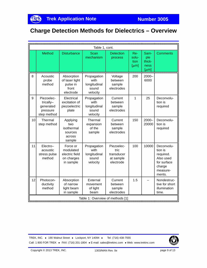
Table 1, cont.
Method Disturbance Scanmechanism
Detectionprocess
Re-solu-tion[µm]
Sam-ple
thick-ness[µm]
Comments
8 Acousticprobe
method
Absorptionof laser light
pulse infront
electrode
Propagationwith
longitudinalsound
velocity
Voltagebetweensample
electrodes
200 2000–6000
9 Piezoelec-trically–
generatedpressure
step method
Electricalexcitation ofpiezoelectric
plate
Propagationwith
longitudinalsound
velocity
Currentbetweensample
electrodes
1 25 Deconvolu-tion isrequired
10 Thermalstep method
Applyingtwo
isothermalsourcesacrosssample
Thermalexpansion
of thesample
Currentbetweensample
electrodes
150 2000–20000
Deconvolu-tion isrequired
11 Electro–acoustic
stress pulsemethod
Force ormodulated
electric fieldon chargesin sample
Propagationwith
longitudinalsound
velocity
Piezoelec-tric
transducerat sampleelectrode
100 10000 Deconvolu-tion isrequired.Also usedfor surfacechargemeasure-ments.
12 Photocon-ductivitymethod
Absorptionof narrowlight beamin sample
Externalmovement
of lightbeam
Currentbetweensample
electrodes
1.5 – Nondestruc-tive for shortilluminationtime.
Table 1: Overview of methods [1]
TREK, INC. • 190 Walnut Street • Lockport, NY 14094 • Tel: (716) 438-7555
Call: 1 800 FOR TREK • FAX: (716) 201-1804 • E-mail: [email protected] • Web: www.trekinc.com
page 9 of 13Copyright © 2013 TREK, INC. 1303/MAN Rev. 0e

Trek Application Note Number 3005
Charge Detection Methods for Dielectrics – Overview
Table 1, cont.
Method Disturbance Scanmechanism
Detectionprocess
Re-solu-tion[µm]
Sam-ple
thick-ness[µm]
Comments
13 Spacecharge
mapping
Interactionof polarized
light withfield
Parallelilluminationof samplevolume ormovementof the lightbeam orsample
Photogra-phic
record
200 – Mostly usedontransparentdielectricliquids.
14 Spectro-scopy
Absorptionof excitingradiation in
sample
Externalmovementof radiationsource orsample
Relativechange in
theobservedspectrum
50 – Fewapplications
15 Field probe None Capacitivecoupling to
the field
Current 200 - Non-destructive,surfacecharge tests
Table 1: Overview of methods [1]
References
[1] J Matallana, J. Bigarre, and P. Hourque-bie. Recent experiments on space chargeand transport in polyethylene under high DCfields. 2001 Annual Conference on ElectricalInsulation and Dielectric Phenomena, pages488–491, 2001.
[2] R. E. Collins. Practical application of the ther-mal pulsing technique to the study of elec-trets. Journal of Applied Physics, 51:2973–2986, 1980.
[3] A. S. DeReggi, C. M. Guttmann, F. I. Mop-sik, G. T. Davis, and M. G. Broadhurst. De-
termination of charge or polarization distribu-tion across polymer electrets by the thermalpulse method and Fourier analysis. PhysicsReview Letters, 40:413–416, 1978.
[4] H. VonSeggern. Thermal pulse techniquefor determining charge distribution: Effectof measurement accuracy. Applied PhysicsLetters, 33(2):134–137, 1978.
[5] D. K. Das-Gupta. Space charge and dielec-tric polarization in polymers. In Proceedingsof the 6th International Conference on Prop-erties and Applications of Dielectric Materi-als, volume 1, pages 24–29, Xi’an JiaotongUniversity, Xi’an, China, June 21-26 2000.IEEE, IEEE.
TREK, INC. • 190 Walnut Street • Lockport, NY 14094 • Tel: (716) 438-7555
Call: 1 800 FOR TREK • FAX: (716) 201-1804 • E-mail: [email protected] • Web: www.trekinc.com
page 10 of 13Copyright © 2013 TREK, INC. 1303/MAN Rev. 0e

Trek Application Note Number 3005
Charge Detection Methods for Dielectrics – Overview
[6] S. B. Lang and D. K. Das-Gupta. A techniquefor determination the polarization distributionin thin polymer electrets using periodic heat-ing. Ferroelectrics, 39:151–154, 1981.
[7] G. M. Sessler, J. E. West, and G. Ger-hard. High resolution laser pulse method formeasuring charge distributions in dielectrics.Physics Review Letters, 48(8):563–566,1982.
[8] G. M. Sessler, R. Gerhard-Multhaupt,H. Seggern, and J. E. West. Charge andpolarization profiles in polymer electrets.IEEE Transactions on Electrical Insulation,21(3):411–415, 1986.
[9] E. Motyl. Pressure methods of space chargemeasurement in dielectrics. Journal of Elec-trostatics, (40/41):469–476, 1997.
[10] F. Chapeau, C. Alquié, J. Lewiner, H. Auclair,Y. Pelet, and R. Jocteur. Pulsed laser de-termination of surface electric charge distri-bution. Journal of Physics: Letters, 43:687–693, 1982.
[11] C. Alquié, J. Lewiner, and G. Dreyfus. Anal-ysis of laser induced acoustic pulse probingof charge distributions in dielectric. Journalof Physics: Letters, 44:171–178, 1981.
[12] R. A. Anderson and S. R. Kurtz. Propertiesof the metal-polymer interface observed withspace charge mapping techniques. Journalof Applied Physics, 60:681–687, 1984.
[13] A. Tanaka, M. Maeda, and T. Takada. Obser-vation of charge behavior in organic photo-conductor using pressure-wave propagationmethod. IEEE Transactions on Electrical In-sulation, 27(3):440–444, 1991.
[14] A. Migliori and J. D. Thompson. A nonde-structive acoustic electric field probe. Jour-nal of Applied Physics, 51:479–485, 1980.
[15] A. Migliori and T. Holfer. Use of laser gener-ated acoustic pulses to measure electric fieldinside a solid dielectric. Review of ScientificInstrumentation, 5:662–666, 1982.
[16] A. G. Rozno and V. V. Gromov. Electriccharge distribution and radiation effects in ir-radiated dielectrics. IEEE Transactions onElectrical Insulation, 21:419–425, 1986.
[17] T Takada and T. Sakai. Measurement ofelectric fields at a dielectric/electrode inter-face using an electric transducer technique.IEEE Transactions on Electrical Insulation,18(6):619–628, 1983.
[18] A. Vázquez, G. Chen, A.E. Davies, andR. Bosch. Space charge measurement usingpulsed electroacoustic technique and signalrecovery. Journal of the European CeramicSociety, 19:1219–1222, 1999.
[19] T. Takada. Acoustic and optical methods formeasuring electric charge distribution in di-electrics. IEEE Transactions on Electrical In-sulation, 6(5):519–547, October 1999.
[20] A. Toureille, M. Abou Dakka, and A. Cher-ifi. Measurement and Localization of SpaceCharge in Insulating Materials. Wroclaw –Szklarska Poreba, Poland, 1990.
[21] P. Notingher Jr., S. Agnel, A. Toureille,B. Rousset, and J.-L. Sanchez. Charac-terization of electric charge in non irradi-ated MOS structures by thermal step andcapacitance-voltage measurements. 2002Annual Report Conference on Electrical In-sulation and Dielectrical Phenomena, pages95–100, 2002.
[22] J. M. Reboul, A. Cherifi, and R. Carin. A newmethod for space charge measurements indielectric films for power capacitors. IEEETransactions on Dielectrics and Electrical In-sulation, 8(5):753–759, October 2001.
TREK, INC. • 190 Walnut Street • Lockport, NY 14094 • Tel: (716) 438-7555
Call: 1 800 FOR TREK • FAX: (716) 201-1804 • E-mail: [email protected] • Web: www.trekinc.com
page 11 of 13Copyright © 2013 TREK, INC. 1303/MAN Rev. 0e

Trek Application Note Number 3005
Charge Detection Methods for Dielectrics – Overview
[23] S. Malrieu and J. Castellon. Space chargemeasurements by the thermal step method:results in some polymers. Journal of Electro-static, (40/41):283–288, 1997.
[24] T. F. Carruthers, J. F. Weller, S. C. Binari, andP. E. Thompson. Electric field distributionsin planar transferred electron devices mea-sured with picosecond optical pulses. IEEEElectron Devices Letters, 3:347–349, 1982.
[25] A. Dias Tavares. New method for the de-termination of space charge in dielectric.Journal of Chemical Physics, 59:2154–2155,1973.
[26] D. K. Davies. The examination of the electri-cal properties of insulators by surface chargemeasurements. Journal of Scientific Instru-mentation, 44:521–524, 1967.
[27] Lord Kelvin. Contact electricity of metals.Philos. Mag., 46:82–120, 1898.
[28] E. J. Yarmchuk and G. E. Keefe. High-resolution surface charge measurements onan organic photoreceptor. Journal of AppliedPhysics, 66(11):5435, 1989.
[29] R. E. Vosteen. Electrostatic voltage followercircuit for use as a voltmeter. U. S. patent no.3525936, 1970.
[30] R. E. Vosteen. Electrostatic potential andfield measurement apparatus having a ca-pacitor detector with feedback to drive thecapacitor detector to the potential beingmeasured. U. S. patent no. 3611127, 1971.
[31] R. E. Vosteen. High level non-contacting dy-namic voltage follower for voltage measure-ment of electrostatically charged surfaces. U.S. patent no. 3729675, 1973.
[32] R. F. Buchheit. Distance compensated elec-trostatic voltmeter. U. S. patent no. 4106869,1978.
[33] B. T. Williams. High speed electrostatic volt-meter. U. S. patent no. 4205267, 1980.
[34] B. T. Williams. Low impedance electrostaticdetector. U. S. patent no. 4370616, 1983.
[35] B. T. Williams. High voltage electrostaticsurface potential monitoring system usinglow voltage a.c. feedback. U. S. patent no.4797620, 1989.
[36] D. M. G. Preethichandra. A simple interfacecircuit to measure very small capacitancechanges in capacitive sensors. IEEE Trans.Instrum. Meas., 50(6):1583–1586, Decem-ber 2001.
[37] V. I. Struminsky. Vibrating-wire transducersfor electrostatic measurements. J. Electro-statics, 54:301–310, 2002.
[38] D. M. Zacher. Feedback-based field metereliminates need for HV source. EE Eval.Eng., pages S43–S45, November 1995.
[39] M. Zahn, T. Takada, and S. H. Voldman. Kerrelectro-optic field mapping measurement inwater using parallel cylindrical electrodes.Journal of Applied Physics, 54(9):4749–4761, 1983.
[40] Y. Yamano, Y. Miyauchi, S. Kobayashi, andY. Saito. Measurement of surface charge dis-tributions on insulating films under AC elec-tric field in vacuum by Pockel effect. InIEEE, editor, Proceedings of XXth Interna-tional Symposium on Discharges and Elec-trical Insulation in Vacuum, volume 1, pages660–663, Tours, 2002. IEEE, IEEE.
[41] F. Cecelja, M. Bordovsky, and W. Balachan-dran. Electro-optic sensor for measurementof DC fields in the presence of space charge.IEEE Transactions on Instrumentation andMeasurement, 51(2):282–286, 2002.
TREK, INC. • 190 Walnut Street • Lockport, NY 14094 • Tel: (716) 438-7555
Call: 1 800 FOR TREK • FAX: (716) 201-1804 • E-mail: [email protected] • Web: www.trekinc.com
page 12 of 13Copyright © 2013 TREK, INC. 1303/MAN Rev. 0e

Trek Application Note Number 3005
Charge Detection Methods for Dielectrics – Overview
[42] M. Zahn, M. Hikita, K. A. Wright, C. M.Cooke, and J. Brennan. Kerr electroop-tical field mapping measurements in elec-tron beam irradiated polymethylmethacry-late. IEEE Transactions on Electrical Insu-lation, 22(2):181–185, 1987.
[43] S. J. Sheng and D. M. Hanson. Spectro-scopic measurement of the space chargedistribution in insulators. Journal of AppliedPhysics, 45:4954–4956, 1974.
[44] N. H. Ahmed and N. N. Srinivas. Review ofspace charge measurements in dielectrics.
IEEE Transactions on Dielectrics and Elec-trical Insulation, 4(5):644–656, 1997.
[45] Alquié. Evolution of space charge mea-surements: new approaches to physicalproblems. In Proceedings of 10th Interna-tional Symposium on Electrets, pages 11–18. IEEE, IEEE, 1999.
[46] Y. Zhang, J. Li, Z. Peng, X. Oin, andZ. Xia. Research of space charge in solid di-electrics in China. IEEE Electrical InsulationMagazine, 17(5):25–30, September/October2001.
TREK, INC. • 190 Walnut Street • Lockport, NY 14094 • Tel: (716) 438-7555
Call: 1 800 FOR TREK • FAX: (716) 201-1804 • E-mail: [email protected] • Web: www.trekinc.com
page 13 of 13Copyright © 2013 TREK, INC. 1303/MAN Rev. 0e